Configuring and managing networking
Managing network interfaces and advanced networking features
Abstract
Providing feedback on Red Hat documentation
We are committed to providing high-quality documentation and value your feedback. To help us improve, you can submit suggestions or report errors through the Red Hat Jira tracking system.
Procedure
Log in to the Jira website.
If you do not have an account, select the option to create one.
- Click Create in the top navigation bar.
- Enter a descriptive title in the Summary field.
- Enter your suggestion for improvement in the Description field. Include links to the relevant parts of the documentation.
- Click Create at the bottom of the window.
Chapter 1. Implementing consistent network interface naming
The udev device manager implements consistent device naming in Red Hat Enterprise Linux. The device manager supports different naming schemes and, by default, assigns fixed names based on firmware, topology, and location information.
Without consistent device naming, the Linux kernel assigns names to network interfaces by combining a fixed prefix and an index. The index increases as the kernel initializes the network devices. For example, eth0 represents the first Ethernet device being probed on start-up. If you add another network interface controller to the system, the assignment of the kernel device names is no longer fixed because, after a reboot, the devices can initialize in a different order. In that case, the kernel can name the devices differently.
To solve this problem, udev assigns consistent device names. This has the following advantages:
- Device names are stable across reboots.
- Device names stay fixed even if you add or remove hardware.
- Defective hardware can be seamlessly replaced.
- The network naming is stateless and does not require explicit configuration files.
Generally, Red Hat does not support systems where consistent device naming is disabled.
Additional resources
1.1. How the udev device manager renames network interfaces
The udev device manager processes a set of rules to implement a consistent naming scheme for network interfaces.
Order of rule files:
Only on Dell systems:
/usr/lib/udev/rules.d/71-biosdevname.rulesThis file exists only if the
biosdevnamepackage is installed, and the rules file defines that thebiosdevnameutility renames the interface according to its naming policy, if it was not renamed in the previous step.NoteInstall and use
biosdevnameonly on Dell systems./usr/lib/udev/rules.d/75-net-description.rulesThis file defines how
udevexamines the network interface and sets the properties inudev-internal variables. These variables are then processed in the next step by the/usr/lib/udev/rules.d/80-net-setup-link.rulesfile. Some of the properties can be undefined./usr/lib/udev/rules.d/80-net-setup-link.rulesThis file calls the
net_setup_linkbuiltin of theudevservice, andudevrenames the interface based on the order of the policies in theNamePolicyparameter in the/usr/lib/systemd/network/99-default.linkfile.If none of the policies applies,
udevdoes not rename the interface.
1.2. Network interface naming policies
By default, the udev device manager uses the /usr/lib/systemd/network/99-default.link file to determine how it renames interfaces. The NamePolicy parameter in this file defines which naming policies udev applies and in what order.
Default order:
NamePolicy=keep kernel database onboard slot path
The following table describes the different actions of udev based on which policy matches first as specified by the NamePolicy parameter:
| Policy | Description | Example name |
|---|---|---|
| keep |
If the device already has a name that was assigned in the user space, | |
| kernel |
If the kernel indicates that a device name is predictable, |
|
| database |
This policy assigns names based on mappings in the |
|
| onboard | Device names incorporate firmware or BIOS-provided index numbers for onboard devices. |
|
| slot | Device names incorporate firmware or BIOS-provided PCI Express (PCIe) hot-plug slot-index numbers. |
|
| path | Device names incorporate the physical location of the connector of the hardware. |
|
| mac | Device names incorporate the MAC address. By default, Red Hat Enterprise Linux does not use this policy, but administrators can enable it. |
|
1.3. Network interface naming schemes
The udev device manager uses certain stable interface attributes that device drivers provide to generate consistent device names.
If a new udev version changes how the service creates names for certain interfaces, Red Hat adds a new scheme version and documents the details in the systemd.net-naming-scheme(7) man page on your system. By default, Red Hat Enterprise Linux (RHEL) 10 uses the rhel-10.0 naming scheme, even if you install or update to a later minor version of RHEL.
On RHEL 10 you can also use all rhel-8.* and rhel-9.* naming schemes.
If you want to use a scheme other than the default, you can switch the network interface naming scheme.
For further details about the naming schemes for different device types and platforms, see the systemd.net-naming-scheme(7) man page on your system.
1.4. Switching to a different network interface naming scheme
By default, RHEL 10 uses the rhel-10.0 naming scheme, even if you install or update to a later minor version of RHEL. Although the default naming scheme fits in most scenarios, there might be reasons to switch to a different scheme version.
Examples when you must change the naming scheme:
- A new scheme can help to better identify a device if it adds additional attributes, such as a slot number, to an interface name.
-
An new scheme can prevent
udevfrom falling back to the kernel-assigned device names (eth*). This happens if the driver does not provide enough unique attributes for two or more interfaces to generate unique names for them.
Prerequisites
- You have access to the console of the server.
Procedure
List the network interfaces:
# ip link show
2: eno1: <BROADCAST,MULTICAST,UP,LOWER_UP> mtu 1500 qdisc fq_codel state UP mode DEFAULT group default qlen 1000
    link/ether 00:00:5e:00:53:1a brd ff:ff:ff:ff:ff:ff
...
Record the MAC addresses of the interfaces.
Optional: Display the
ID_NET_NAMING_SCHEMEproperty of a network interface to identify the naming scheme that RHEL currently uses:# udevadm info --query=property --property=ID_NET_NAMING_SCHEME /sys/class/net/eno1 ID_NET_NAMING_SCHEME=rhel-10.0Note that the property is not available on the
loloopback device.Append the
net.naming-scheme=<scheme>option to the command line of all installed kernels, for example:# grubby --update-kernel=ALL --args=net.naming-scheme=rhel-10.1Reboot the system.
# rebootBased on the MAC addresses you recorded, identify the new names of network interfaces that have changed due to the different naming scheme:
# ip link show
2: eno1np0: <BROADCAST,MULTICAST,UP,LOWER_UP> mtu 1500 qdisc fq_codel state UP mode DEFAULT group default qlen 1000
    link/ether 00:00:5e:00:53:1a brd ff:ff:ff:ff:ff:ff
...
After switching the scheme,
udevnames the device with the specified MAC addresseno1np0, whereas it was namedeno1before.Identify which NetworkManager connection profile uses an interface with the previous name:
# nmcli -f device,name connection show
DEVICE  NAME
eno1  example_profile
...
Set the
connection.interface-nameproperty in the connection profile to the new interface name:# nmcli connection modify example_profile connection.interface-name "eno1np0"Reactivate the connection profile:
# nmcli connection up example_profile
Verification
Identify the naming scheme that RHEL now uses by displaying the
ID_NET_NAMING_SCHEMEproperty of a network interface:# udevadm info --query=property --property=ID_NET_NAMING_SCHEME /sys/class/net/eno1np0 ID_NET_NAMING_SCHEME=_rhel-10.1
1.5. Customizing the prefix for Ethernet interfaces during installation
If you do not want to use the default device-naming policy for Ethernet interfaces, you can set a custom device prefix during the Red Hat Enterprise Linux (RHEL) installation.
Red Hat supports systems with customized Ethernet prefixes only if you set the prefix during the RHEL installation. Using the prefixdevname utility on already deployed systems is not supported.
If you set a device prefix during the installation, the udev service uses the <prefix><index> format for Ethernet interfaces after the installation. For example, if you set the prefix net, the service assigns the names net0, net1, and so on to the Ethernet interfaces.
The udev service appends the index to the custom prefix, and preserves the index values of known Ethernet interfaces. If you add an interface, udev assigns an index value that is one greater than the previously-assigned index value to the new interface.
Prerequisites
- The prefix consists of ASCII characters.
- The prefix is an alphanumeric string.
- The prefix is shorter than 16 characters.
-
The prefix does not conflict with any other well-known network interface prefix, such as
eth,eno,ens, andem.
Procedure
- Boot the Red Hat Enterprise Linux installation media.
In the boot manager, follow these steps:
- Select the Install Red Hat Enterprise Linux <version> entry.
- Press Tab to edit the entry.
-
Append
net.ifnames.prefix=<prefix>to the kernel options. - Press Enter to start the installation program.
- Install Red Hat Enterprise Linux.
Verification
To verify the interface names, display the network interfaces:
# ip link show
...
2: net0: <BROADCAST,MULTICAST,UP,LOWER_UP> mtu 1500 qdisc fq_codel state UP mode DEFAULT group default qlen 1000
    link/ether 00:00:5e:00:53:1a brd ff:ff:ff:ff:ff:ff
...
1.6. Configuring user-defined network interface names by using udev rules
You can use udev rules to implement custom network interface names that reflect your organization’s requirements.
Procedure
Identify the network interface that you want to rename:
# ip link show
...
enp1s0: <BROADCAST,MULTICAST,UP,LOWER_UP> mtu 1500 qdisc fq_codel state UP mode DEFAULT group default qlen 1000
    link/ether 00:00:5e:00:53:1a brd ff:ff:ff:ff:ff:ff
...
Record the MAC address of the interface.
Display the device type ID of the interface:
# cat /sys/class/net/enp1s0/type
1
Create the
/etc/udev/rules.d/70-persistent-net.rulesfile, and add a rule for each interface that you want to rename:SUBSYSTEM=="net",ACTION=="add",ATTR{address}=="<MAC_address>",ATTR{type}=="<device_type_id>",NAME="<new_interface_name>"ImportantUse only
70-persistent-net.rulesas a file name if you require consistent device names during the boot process. Thedracututility adds a file with this name to theinitrdimage if you regenerate the RAM disk image.For example, use the following rule to rename the interface with MAC address
00:00:5e:00:53:1atoprovider0:SUBSYSTEM=="net",ACTION=="add",ATTR{address}=="00:00:5e:00:53:1a",ATTR{type}=="1",NAME="provider0"Optional: Regenerate the
initrdRAM disk image:# dracut -fYou require this step only if you need networking capabilities in the RAM disk. For example, this is the case if the root file system is stored on a network device, such as iSCSI.
Identify which NetworkManager connection profile uses the interface that you want to rename:
# nmcli -f device,name connection show
DEVICE  NAME
enp1s0  example_profile
...
Unset the
connection.interface-nameproperty in the connection profile:# nmcli connection modify example_profile connection.interface-name ""Temporarily, configure the connection profile to match both the new and the previous interface name:
# nmcli connection modify example_profile match.interface-name "provider0 enp1s0"Reboot the system:
# rebootVerify that the device with the MAC address that you specified in the link file has been renamed to
provider0:# ip link show provider0: <BROADCAST,MULTICAST,UP,LOWER_UP> mtu 1500 qdisc mq state UP mode DEFAULT group default qlen 1000 link/ether 00:00:5e:00:53:1a brd ff:ff:ff:ff:ff:ff ...Configure the connection profile to match only the new interface name:
# nmcli connection modify example_profile match.interface-name "provider0"You have now removed the old interface name from the connection profile.
Reactivate the connection profile:
# nmcli connection up example_profile
1.7. Configuring user-defined network interface names by using systemd link files
You can use systemd link files to implement custom network interface names that reflect your organization’s requirements.
Prerequisites
- NetworkManager does not manage this interface.
Procedure
Identify the network interface that you want to rename:
# ip link show
...
enp1s0: <BROADCAST,MULTICAST,UP,LOWER_UP> mtu 1500 qdisc fq_codel state UP mode DEFAULT group default qlen 1000
    link/ether 00:00:5e:00:53:1a brd ff:ff:ff:ff:ff:ff
...
Record the MAC address of the interface.
If it does not already exist, create the
/etc/systemd/network/directory:# mkdir -p /etc/systemd/network/For each interface that you want to rename, create a
70-*.linkfile in the/etc/systemd/network/directory with the following content:[Match] MACAddress=<MAC_address> [Link] Name=<new_interface_name>ImportantUse a file name with a
70-prefix to keep the file names consistent with theudevrules-based solution.For example, create the
/etc/systemd/network/70-provider0.linkfile with the following content to rename the interface with MAC address00:00:5e:00:53:1atoprovider0:[Match] MACAddress=00:00:5e:00:53:1a [Link] Name=provider0Optional: Regenerate the
initrdRAM disk image:# dracut -fYou require this step only if you need networking capabilities in the RAM disk. For example, this is the case if the root file system is stored on a network device, such as iSCSI.
Identify which NetworkManager connection profile uses the interface that you want to rename:
# nmcli -f device,name connection show
DEVICE  NAME
enp1s0  example_profile
...
Unset the
connection.interface-nameproperty in the connection profile:# nmcli connection modify example_profile connection.interface-name ""Temporarily, configure the connection profile to match both the new and the previous interface name:
# nmcli connection modify example_profile match.interface-name "provider0 enp1s0"Reboot the system:
# rebootVerify that the device with the MAC address that you specified in the link file has been renamed to
provider0:# ip link show provider0: <BROADCAST,MULTICAST,UP,LOWER_UP> mtu 1500 qdisc mq state UP mode DEFAULT group default qlen 1000 link/ether 00:00:5e:00:53:1a brd ff:ff:ff:ff:ff:ff ...Configure the connection profile to match only the new interface name:
# nmcli connection modify example_profile match.interface-name "provider0"You have now removed the old interface name from the connection profile.
Reactivate the connection profile.
# nmcli connection up example_profile
1.8. Assigning alternative names to a network interface by using systemd link files
With alternative interface naming, the kernel can assign additional names to network interfaces. You can use these alternative names in the same way as the normal interface names in commands that require a network interface name.
Prerequisites
- You must use ASCII characters for the alternative name.
- The alternative name must be shorter than 128 characters.
Procedure
Display the network interface names and their MAC addresses:
# ip link show
...
enp1s0: <BROADCAST,MULTICAST,UP,LOWER_UP> mtu 1500 qdisc fq_codel state UP mode DEFAULT group default qlen 1000
    link/ether 00:00:5e:00:53:1a brd ff:ff:ff:ff:ff:ff
...
Record the MAC address of the interface to which you want to assign an alternative name.
If it does not already exist, create the
/etc/systemd/network/directory:# mkdir -p /etc/systemd/network/For each interface that must have an alternative name, create a copy of the
/usr/lib/systemd/network/99-default.linkfile with a unique name and.linksuffix in the/etc/systemd/network/directory, for example:# cp /usr/lib/systemd/network/99-default.link /etc/systemd/network/98-lan.linkModify the file you created in the previous step. Rewrite the
[Match]section as follows, and append theAlternativeNameentries to the[Link]section:[Match] MACAddress=<MAC_address> [Link] ... AlternativeName=<alternative_interface_name_1> AlternativeName=<alternative_interface_name_2> AlternativeName=<alternative_interface_name_n>For example, create the
/etc/systemd/network/70-altname.linkfile with the following content to assignprovideras an alternative name to the interface with MAC address00:00:5e:00:53:1a:[Match] MACAddress=00:00:5e:00:53:1a [Link] NamePolicy=keep kernel database onboard slot path AlternativeNamesPolicy=database onboard slot path mac MACAddressPolicy=none AlternativeName=providerRegenerate the
initrdRAM disk image:# dracut -fReboot the system:
# reboot
Verification
Use the alternative interface name. For example, display the IP address settings of the device with the alternative name
provider:# ip address show provider 2: enp1s0: <BROADCAST,MULTICAST,UP,LOWER_UP> mtu 1500 qdisc fq_codel state UP group default qlen 1000 link/ether 00:00:5e:00:53:1a brd ff:ff:ff:ff:ff:ff altname provider ...
Chapter 2. Configuring an Ethernet connection
NetworkManager creates a connection profile for each Ethernet adapter that is installed in a host. By default, this profile uses DHCP for both IPv4 and IPv6 connections.
Modify the automatically-created profile or add a new one in the following cases:
- The network requires custom settings, such as a static IP address configuration.
- You require multiple profiles because the host roams among different networks.
Red Hat Enterprise Linux provides administrators different options to configure Ethernet connections. For example:
-
Use
nmclito configure connections on the command line. -
Use
nmtuito configure connections in a text-based user interface. - Use the GNOME Settings menu to configure connections in a graphical interface.
-
Use
nmstatectlto configure connections through the Nmstate API. - Use RHEL system roles to automate the configuration of connections on one or multiple hosts.
If you want to manually configure Ethernet connections on hosts running in the Microsoft Azure cloud, disable the cloud-init service or configure it to ignore the network settings retrieved from the cloud environment. Otherwise, cloud-init overrides on the next reboot the network settings that you have manually configured.
2.1. Configuring an Ethernet connection by using nmcli
If you connect a host to the network over Ethernet, you can manage the connection’s settings on the command line by using the nmcli utility.
Prerequisites
- A physical or virtual Ethernet Network Interface Controller (NIC) exists in the server’s configuration.
Procedure
List the NetworkManager connection profiles:
# nmcli connection show
NAME                UUID                                  TYPE      DEVICE
Wired connection 1  a5eb6490-cc20-3668-81f8-0314a27f3f75  ethernet  enp1s0
By default, NetworkManager creates a profile for each NIC in the host. If you plan to connect this NIC only to a specific network, adapt the automatically-created profile. If you plan to connect this NIC to networks with different settings, create individual profiles for each network.
If you want to create an additional connection profile, enter:
# nmcli connection add con-name <connection-name> ifname <device-name> type ethernetSkip this step to modify an existing profile.
Optional: Rename the connection profile:
# nmcli connection modify "Wired connection 1" connection.id "Internal-LAN"On hosts with multiple profiles, a meaningful name makes it easier to identify the purpose of a profile.
Display the current settings of the connection profile:
# nmcli connection show Internal-LAN
...
connection.interface-name:     enp1s0
connection.autoconnect:        yes
ipv4.method:                   auto
ipv6.method:                   auto
...
Configure the IPv4 settings:
To use DHCP, enter:
# nmcli connection modify Internal-LAN ipv4.method autoSkip this step if
ipv4.methodis already set toauto(default).To set a static IPv4 address, network mask, default gateway, DNS servers, and search domain, enter:
# nmcli connection modify Internal-LAN ipv4.method manual ipv4.addresses 192.0.2.1/24 ipv4.gateway 192.0.2.254 ipv4.dns 192.0.2.200 ipv4.dns-search example.com
Configure the IPv6 settings:
To use stateless address autoconfiguration (SLAAC), enter:
# nmcli connection modify Internal-LAN ipv6.method autoSkip this step if
ipv6.methodis already set toauto(default).To set a static IPv6 address, network mask, default gateway, DNS servers, and search domain, enter:
# nmcli connection modify Internal-LAN ipv6.method manual ipv6.addresses 2001:db8:1::fffe/64 ipv6.gateway 2001:db8:1::fffe ipv6.dns 2001:db8:1::ffbb ipv6.dns-search example.com
To customize other settings in the profile, use the following command:
# nmcli connection modify <connection-name> <setting> <value>Enclose values with spaces or semicolons in quotes.
For details about which settings you can modify, see the
nm-settings(5)man page on your system.Activate the profile:
# nmcli connection up Internal-LAN
Verification
Display the IP settings of the NIC:
# ip address show enp1s0
2: enp1s0: <BROADCAST,MULTICAST,UP,LOWER_UP> mtu 1500 qdisc fq_codel state UP group default qlen 1000
    link/ether 52:54:00:17:b8:b6 brd ff:ff:ff:ff:ff:ff
    inet 192.0.2.1/24 brd 192.0.2.255 scope global noprefixroute enp1s0
       valid_lft forever preferred_lft forever
    inet6 2001:db8:1::fffe/64 scope global noprefixroute
       valid_lft forever preferred_lft forever
Display the IPv4 default gateway:
# ip route show default
default via 192.0.2.254 dev enp1s0 proto static metric 102
Display the IPv6 default gateway:
# ip -6 route show default
default via 2001:db8:1::fffe dev enp1s0 proto static metric 102 pref medium
Display the DNS settings:
# cat /etc/resolv.conf
search example.com
nameserver 192.0.2.200
nameserver 2001:db8:1::ffbb
If multiple connection profiles are active at the same time, the order of
nameserverentries depend on the DNS priority values in these profiles and the connection types.Use the
pingutility to verify that this host can send packets to other hosts:# ping <host-name-or-IP-address>
Troubleshooting
- Verify that the network cable is plugged-in to the host and a switch.
- Check whether the link failure exists only on this host or also on other hosts connected to the same switch.
- Verify that the network cable and the network interface are working as expected. Perform hardware diagnosis steps and replace defective cables and network interface cards.
- If the configuration on the disk does not match the configuration on the device, starting or restarting NetworkManager creates an in-memory connection that reflects the configuration of the device. For further details and how to avoid this problem, see the Red Hat Knowledgebase solution NetworkManager duplicates a connection after restart of NetworkManager service.
2.2. Configuring an Ethernet connection by using nmtui
If you connect a host to an Ethernet network, you can manage the connection’s settings in a text-based user interface. Use the nmtui application to create new profiles and to update existing ones on a host without a graphical interface.
In nmtui:
- Navigate by using the cursor keys.
- Press a button by selecting it and hitting Enter.
- Select and clear checkboxes by using Space.
- To return to the previous screen, use ESC.
Prerequisites
- A physical or virtual Ethernet Network Interface Controller (NIC) exists in the server’s configuration.
Procedure
If you do not know the network device name you want to use in the connection, display the available devices:
# nmcli device status
DEVICE     TYPE      STATE                   CONNECTION
enp1s0     ethernet  unavailable             --
...
Start
nmtui:# nmtui- Select Edit a connection, and press Enter.
Choose whether to add a new connection profile or to modify an existing one:
To create a new profile:
- Press Add.
- Select Ethernet from the list of network types, and press Enter.
- To modify an existing profile, select the profile from the list, and press Enter.
Optional: Update the name of the connection profile.
On hosts with multiple profiles, a meaningful name makes it easier to identify the purpose of a profile.
- If you create a new connection profile, enter the network device name into the Device field.
Depending on your environment, configure the IP address settings in the
IPv4 configurationandIPv6 configurationareas accordingly. For this, press the button next to these areas, and select:- Disabled, if this connection does not require an IP address.
- Automatic, if a DHCP server dynamically assigns an IP address to this NIC.
Manual, if the network requires static IP address settings. In this case, you must fill further fields:
- Press Show next to the protocol you want to configure to display additional fields.
Press Add next to Addresses, and enter the IP address and the subnet mask in Classless Inter-Domain Routing (CIDR) format.
If you do not specify a subnet mask, NetworkManager sets a
/32subnet mask for IPv4 addresses and/64for IPv6 addresses.- Enter the address of the default gateway.
- Press Add next to DNS servers, and enter the DNS server address.
- Press Add next to Search domains, and enter the DNS search domain.
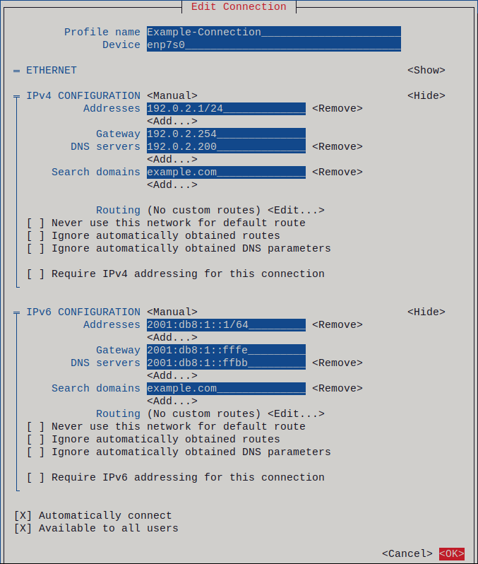
Figure 2.1. Example of an Ethernet connection with static IP address settings
- Press OK to create and automatically activate the new connection.
- Press Back to return to the main menu.
-
Select Quit, and press Enter to close the
nmtuiapplication.
Verification
Display the IP settings of the NIC:
# ip address show enp1s0
2: enp1s0: <BROADCAST,MULTICAST,UP,LOWER_UP> mtu 1500 qdisc fq_codel state UP group default qlen 1000
    link/ether 52:54:00:17:b8:b6 brd ff:ff:ff:ff:ff:ff
    inet 192.0.2.1/24 brd 192.0.2.255 scope global noprefixroute enp1s0
       valid_lft forever preferred_lft forever
    inet6 2001:db8:1::fffe/64 scope global noprefixroute
       valid_lft forever preferred_lft forever
Display the IPv4 default gateway:
# ip route show default
default via 192.0.2.254 dev enp1s0 proto static metric 102
Display the IPv6 default gateway:
# ip -6 route show default
default via 2001:db8:1::fffe dev enp1s0 proto static metric 102 pref medium
Display the DNS settings:
# cat /etc/resolv.conf
search example.com
nameserver 192.0.2.200
nameserver 2001:db8:1::ffbb
If multiple connection profiles are active at the same time, the order of
nameserverentries depend on the DNS priority values in these profiles and the connection types.Use the
pingutility to verify that this host can send packets to other hosts:# ping <host-name-or-IP-address>
Troubleshooting
- Verify that the network cable is plugged-in to the host and a switch.
- Check whether the link failure exists only on this host or also on other hosts connected to the same switch.
- Verify that the network cable and the network interface are working as expected. Perform hardware diagnosis steps and replace defective cables and network interface cards.
- If the configuration on the disk does not match the configuration on the device, starting or restarting NetworkManager creates an in-memory connection that reflects the configuration of the device. For further details and how to avoid this problem, see the Red Hat Knowledgebase solution NetworkManager duplicates a connection after restart of NetworkManager service.
2.3. Configuring an Ethernet connection by using control-center
If you connect a host to the network over Ethernet, you can manage the connection’s settings with a graphical interface by using the GNOME Settings menu.
Note that control-center does not support as many configuration options as the nmcli utility.
Prerequisites
- A physical or virtual Ethernet Network Interface Controller (NIC) exists in the server’s configuration.
- GNOME is installed.
Procedure
-
Press the Super key, enter
Settings, and press Enter. - Select Network in the navigation on the left.
Choose whether to add a new connection profile or to modify an existing one:
- To create a new profile, click the button next to the Ethernet entry.
- To modify an existing profile, click the gear icon next to the profile entry.
Optional: On the Identity tab, update the name of the connection profile.
On hosts with multiple profiles, a meaningful name makes it easier to identify the purpose of a profile.
Depending on your environment, configure the IP address settings on the IPv4 and IPv6 tabs accordingly:
-
To use DHCP or IPv6 stateless address autoconfiguration (SLAAC), select
Automatic (DHCP)as method (default). To set a static IP address, network mask, default gateway, DNS servers, and search domain, select
Manualas method, and fill the fields on the tabs: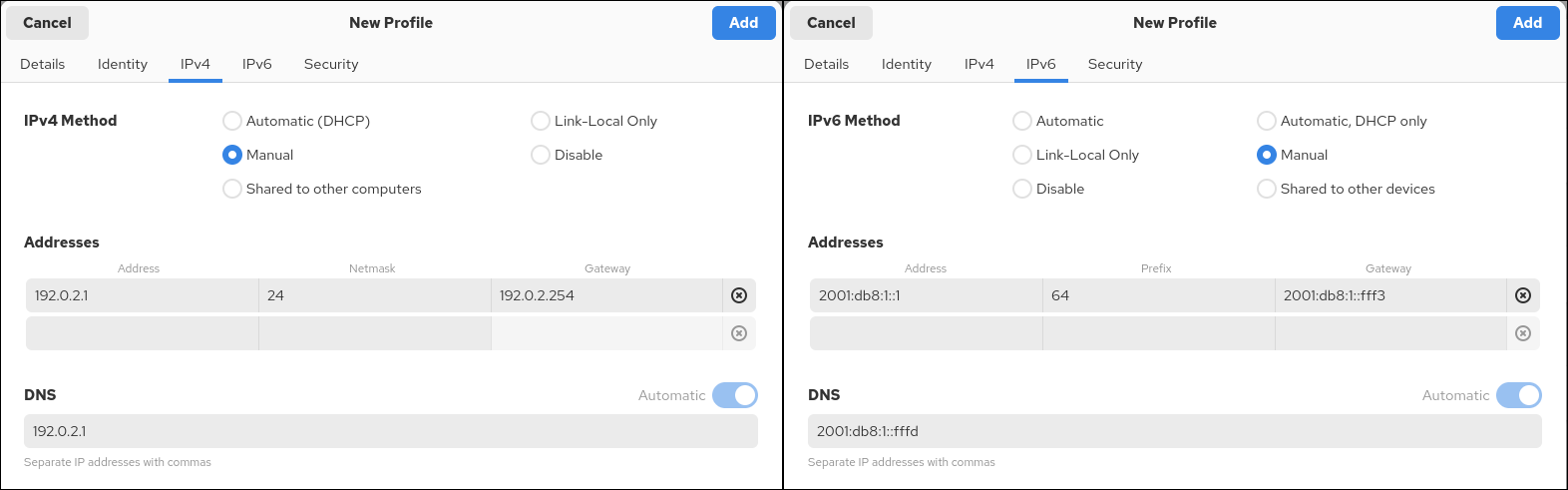
-
To use DHCP or IPv6 stateless address autoconfiguration (SLAAC), select
Depending on whether you add or modify a connection profile, click the or button to save the connection.
The GNOME
control-centerautomatically activates the connection.
Verification
Display the IP settings of the NIC:
# ip address show enp1s0
2: enp1s0: <BROADCAST,MULTICAST,UP,LOWER_UP> mtu 1500 qdisc fq_codel state UP group default qlen 1000
    link/ether 52:54:00:17:b8:b6 brd ff:ff:ff:ff:ff:ff
    inet 192.0.2.1/24 brd 192.0.2.255 scope global noprefixroute enp1s0
       valid_lft forever preferred_lft forever
    inet6 2001:db8:1::fffe/64 scope global noprefixroute
       valid_lft forever preferred_lft forever
Display the IPv4 default gateway:
# ip route show default
default via 192.0.2.254 dev enp1s0 proto static metric 102
Display the IPv6 default gateway:
# ip -6 route show default
default via 2001:db8:1::fffe dev enp1s0 proto static metric 102 pref medium
Display the DNS settings:
# cat /etc/resolv.conf
search example.com
nameserver 192.0.2.200
nameserver 2001:db8:1::ffbb
If multiple connection profiles are active at the same time, the order of
nameserverentries depend on the DNS priority values in these profiles and the connection types.Use the
pingutility to verify that this host can send packets to other hosts:# ping <host-name-or-IP-address>
Troubleshooting steps
- Verify that the network cable is plugged-in to the host and a switch.
- Check whether the link failure exists only on this host or also on other hosts connected to the same switch.
- Verify that the network cable and the network interface are working as expected. Perform hardware diagnosis steps and replace defective cables and network interface cards.
- If the configuration on the disk does not match the configuration on the device, starting or restarting NetworkManager creates an in-memory connection that reflects the configuration of the device. For further details and how to avoid this problem, see the Red Hat Knowledgebase solution NetworkManager duplicates a connection after restart of NetworkManager service.
2.4. Configuring an Ethernet connection with a static IP address by using nmstatectl with an interface name
You can use the declarative Nmstate API to configure an Ethernet connection with static IP addresses, gateways, and DNS settings, and assign them to a specified interface name. Nmstate ensures that the result matches the configuration file or rolls back the changes.
Prerequisites
- A physical or virtual Ethernet Network Interface Controller (NIC) exists in the server’s configuration.
-
The
nmstatepackage is installed.
Procedure
Create a YAML file, for example
~/create-ethernet-profile.yml, with the following content:--- interfaces: - name: enp1s0 type: ethernet state: up ipv4: enabled: true address: - ip: 192.0.2.1 prefix-length: 24 dhcp: false ipv6: enabled: true address: - ip: 2001:db8:1::1 prefix-length: 64 autoconf: false dhcp: false routes: config: - destination: 0.0.0.0/0 next-hop-address: 192.0.2.254 next-hop-interface: enp1s0 - destination: ::/0 next-hop-address: 2001:db8:1::fffe next-hop-interface: enp1s0 dns-resolver: config: search: - example.com server: - 192.0.2.200 - 2001:db8:1::ffbbThese settings define an Ethernet connection profile for the
enp1s0device with the following settings:-
A static IPv4 address -
192.0.2.1with the/24subnet mask -
A static IPv6 address -
2001:db8:1::1with the/64subnet mask -
An IPv4 default gateway -
192.0.2.254 -
An IPv6 default gateway -
2001:db8:1::fffe -
An IPv4 DNS server -
192.0.2.200 -
An IPv6 DNS server -
2001:db8:1::ffbb -
A DNS search domain -
example.com
-
A static IPv4 address -
Optional: You can define the
identifier: mac-addressandmac-address: <mac_address>properties in theinterfacesproperty to identify the network interface card by its MAC address instead of its name, for example:--- interfaces: - name: <profile_name> type: ethernet identifier: mac-address mac-address: <mac_address> ...Apply the settings to the system:
# nmstatectl apply ~/create-ethernet-profile.yml
Verification
Display the current state in YAML format:
# nmstatectl show enp1s0Display the IP settings of the NIC:
# ip address show enp1s0
2: enp1s0: <BROADCAST,MULTICAST,UP,LOWER_UP> mtu 1500 qdisc fq_codel state UP group default qlen 1000
    link/ether 52:54:00:17:b8:b6 brd ff:ff:ff:ff:ff:ff
    inet 192.0.2.1/24 brd 192.0.2.255 scope global noprefixroute enp1s0
       valid_lft forever preferred_lft forever
    inet6 2001:db8:1::fffe/64 scope global noprefixroute
       valid_lft forever preferred_lft forever
Display the IPv4 default gateway:
# ip route show default
default via 192.0.2.254 dev enp1s0 proto static metric 102
Display the IPv6 default gateway:
# ip -6 route show default
default via 2001:db8:1::fffe dev enp1s0 proto static metric 102 pref medium
Display the DNS settings:
# cat /etc/resolv.conf
search example.com
nameserver 192.0.2.200
nameserver 2001:db8:1::ffbb
If multiple connection profiles are active at the same time, the order of
nameserverentries depend on the DNS priority values in these profiles and the connection types.Use the
pingutility to verify that this host can send packets to other hosts:# ping <host-name-or-IP-address>
2.5. Configuring an Ethernet connection with a static IP address by using nmstatectl with a PCI address
You can use the declarative Nmstate API to configure an Ethernet connection with static IP addresses, gateways, and DNS settings, and assign them to a device based on its PCI address. Nmstate ensures that the result matches the configuration file or rolls back the changes.
Prerequisites
- A physical Ethernet Network Interface Controller (NIC) exists in the server’s configuration.
-
You know the PCI address of the device. You can display the PCI address by using the
ethtool -i <interface_name> | grep bus-infocommand. -
The
nmstatepackage is installed.
Procedure
Create a YAML file, for example
~/create-ethernet-profile.yml, with the following content:--- interfaces: - name: <profile_name> type: ethernet state: up identifier: pci-address pci-address: 0000:00:14.3 ipv4: enabled: true address: - ip: 192.0.2.1 prefix-length: 24 dhcp: false ipv6: enabled: true address: - ip: 2001:db8:1::1 prefix-length: 64 autoconf: false dhcp: false routes: config: - destination: 0.0.0.0/0 next-hop-address: 192.0.2.254 next-hop-interface: <profile_name> - destination: ::/0 next-hop-address: 2001:db8:1::fffe next-hop-interface: <profile_name> dns-resolver: config: search: - example.com server: - 192.0.2.200 - 2001:db8:1::ffbbThese settings define an Ethernet connection profile for the device with the ID
0000:00:14.3with the following settings:-
A static IPv4 address -
192.0.2.1with the/24subnet mask -
A static IPv6 address -
2001:db8:1::1with the/64subnet mask -
An IPv4 default gateway -
192.0.2.254 -
An IPv6 default gateway -
2001:db8:1::fffe -
An IPv4 DNS server -
192.0.2.200 -
An IPv6 DNS server -
2001:db8:1::ffbb -
A DNS search domain -
example.com
-
A static IPv4 address -
Apply the settings to the system:
# nmstatectl apply ~/create-ethernet-profile.yml
Verification
Display the current state in YAML format:
# nmstatectl show <interface_name>Display the IP settings of the NIC:
# ip address show <interface_name>
2: :<interface_name> <BROADCAST,MULTICAST,UP,LOWER_UP> mtu 1500 qdisc fq_codel state UP group default qlen 1000
    link/ether 52:54:00:17:b8:b6 brd ff:ff:ff:ff:ff:ff
    inet 192.0.2.1/24 brd 192.0.2.255 scope global noprefixroute <interface_name>
       valid_lft forever preferred_lft forever
    inet6 2001:db8:1::fffe/64 scope global noprefixroute
       valid_lft forever preferred_lft forever
Display the IPv4 default gateway:
# ip route show default
default via 192.0.2.254 dev <interface_name> proto static metric 102
Display the IPv6 default gateway:
# ip -6 route show default
default via 2001:db8:1::fffe dev <interface_name> proto static metric 102 pref medium
Display the DNS settings:
# cat /etc/resolv.conf
search example.com
nameserver 192.0.2.200
nameserver 2001:db8:1::ffbb
Use the
pingutility to verify that this host can send packets to other hosts:# ping <host-name-or-IP-address>
2.6. Configuring an Ethernet connection with a static IP address by using the network RHEL system role with an interface name
You can use the network RHEL system role to configure an Ethernet connection with static IP addresses, gateways, and DNS settings, and assign them to a specified interface name.
To connect a Red Hat Enterprise Linux host to an Ethernet network, create a NetworkManager connection profile for the network device. By using Ansible and the network RHEL system role, you can automate this process and remotely configure connection profiles on the hosts defined in a playbook.
Typically, administrators want to reuse a playbook and not maintain individual playbooks for each host to which Ansible assigns static IP addresses. In this case, you can use variables in the playbook and maintain the settings in the inventory. As a result, you need only one playbook to dynamically assign individual settings to multiple hosts.
Prerequisites
- You have prepared the control node and the managed nodes.
- You are logged in to the control node as a user who can run playbooks on the managed nodes.
-
The account you use to connect to the managed nodes has
sudopermissions for these nodes. - A physical or virtual Ethernet device exists in the server configuration.
- The managed nodes use NetworkManager to configure the network.
Procedure
Edit the
~/inventoryfile, and append the host-specific settings to the host entries:managed-node-01.example.com interface=enp1s0 ip_v4=192.0.2.1/24 ip_v6=2001:db8:1::1/64 gateway_v4=192.0.2.254 gateway_v6=2001:db8:1::fffe managed-node-02.example.com interface=enp1s0 ip_v4=192.0.2.2/24 ip_v6=2001:db8:1::2/64 gateway_v4=192.0.2.254 gateway_v6=2001:db8:1::fffeCreate a playbook file, for example,
~/playbook.yml, with the following content:--- - name: Configure the network hosts: managed-node-01.example.com,managed-node-02.example.com tasks: - name: Ethernet connection profile with static IP address settings ansible.builtin.include_role: name: redhat.rhel_system_roles.network vars: network_connections: - name: "{{ interface }}" interface_name: "{{ interface }}" type: ethernet autoconnect: yes ip: address: - "{{ ip_v4 }}" - "{{ ip_v6 }}" gateway4: "{{ gateway_v4 }}" gateway6: "{{ gateway_v6 }}" dns: - 192.0.2.200 - 2001:db8:1::ffbb dns_search: - example.com state: upThis playbook reads certain values dynamically for each host from the inventory file and uses static values in the playbook for settings which are the same for all hosts.
For details about all variables used in the playbook, see the
/usr/share/ansible/roles/rhel-system-roles.network/README.mdfile on the control node.Validate the playbook syntax:
$ ansible-playbook --syntax-check ~/playbook.ymlNote that this command only validates the syntax and does not protect against a wrong but valid configuration.
Run the playbook:
$ ansible-playbook ~/playbook.yml
Verification
Query the Ansible facts of the managed node and verify the active network settings:
# ansible managed-node-01.example.com -m ansible.builtin.setup
...
        "ansible_default_ipv4": {
            "address": "192.0.2.1",
            "alias": "enp1s0",
            "broadcast": "192.0.2.255",
            "gateway": "192.0.2.254",
            "interface": "enp1s0",
            "macaddress": "52:54:00:17:b8:b6",
            "mtu": 1500,
            "netmask": "255.255.255.0",
            "network": "192.0.2.0",
            "prefix": "24",
            "type": "ether"
        },
        "ansible_default_ipv6": {
            "address": "2001:db8:1::1",
            "gateway": "2001:db8:1::fffe",
            "interface": "enp1s0",
            "macaddress": "52:54:00:17:b8:b6",
            "mtu": 1500,
            "prefix": "64",
            "scope": "global",
            "type": "ether"
        },
        ...
        "ansible_dns": {
            "nameservers": [
                "192.0.2.1",
                "2001:db8:1::ffbb"
            ],
            "search": [
                "example.com"
            ]
        },
...
2.7. Configuring an Ethernet connection with a static IP address by using the network RHEL system role with a device path
You can use the network RHEL system role to configure an Ethernet connection with static IP addresses, gateways, and DNS settings, and assign them to a device based on its path instead of its name.
To connect a Red Hat Enterprise Linux host to an Ethernet network, create a NetworkManager connection profile for the network device. By using Ansible and the network RHEL system role, you can automate this process and remotely configure connection profiles on the hosts defined in a playbook.
Prerequisites
- You have prepared the control node and the managed nodes.
- You are logged in to the control node as a user who can run playbooks on the managed nodes.
-
The account you use to connect to the managed nodes has
sudopermissions for these nodes. - A physical or virtual Ethernet device exists in the server’s configuration.
- The managed nodes use NetworkManager to configure the network.
-
You know the path of the device. You can display the device path by using the
udevadm info /sys/class/net/<device_name> | grep ID_PATH=command.
Procedure
Create a playbook file, for example,
~/playbook.yml, with the following content:--- - name: Configure the network hosts: managed-node-01.example.com tasks: - name: Ethernet connection profile with static IP address settings ansible.builtin.include_role: name: redhat.rhel_system_roles.network vars: network_connections: - name: example match: path: - pci-0000:00:0[1-3].0 - '&!pci-0000:00:02.0' type: ethernet autoconnect: yes ip: address: - 192.0.2.1/24 - 2001:db8:1::1/64 gateway4: 192.0.2.254 gateway6: 2001:db8:1::fffe dns: - 192.0.2.200 - 2001:db8:1::ffbb dns_search: - example.com state: upThe settings specified in the example playbook include the following:
match-
Defines that a condition must be met in order to apply the settings. You can only use this variable with the
pathoption. path-
Defines the persistent path of a device. You can set it as a fixed path or an expression. Its value can contain modifiers and wildcards. The example applies the settings to devices that match PCI ID
0000:00:0[1-3].0, but not0000:00:02.0.
For details about all variables used in the playbook, see the
/usr/share/ansible/roles/rhel-system-roles.network/README.mdfile on the control node.Validate the playbook syntax:
$ ansible-playbook --syntax-check ~/playbook.ymlNote that this command only validates the syntax and does not protect against a wrong but valid configuration.
Run the playbook:
$ ansible-playbook ~/playbook.yml
Verification
Query the Ansible facts of the managed node and verify the active network settings:
# ansible managed-node-01.example.com -m ansible.builtin.setup
...
        "ansible_default_ipv4": {
            "address": "192.0.2.1",
            "alias": "enp1s0",
            "broadcast": "192.0.2.255",
            "gateway": "192.0.2.254",
            "interface": "enp1s0",
            "macaddress": "52:54:00:17:b8:b6",
            "mtu": 1500,
            "netmask": "255.255.255.0",
            "network": "192.0.2.0",
            "prefix": "24",
            "type": "ether"
        },
        "ansible_default_ipv6": {
            "address": "2001:db8:1::1",
            "gateway": "2001:db8:1::fffe",
            "interface": "enp1s0",
            "macaddress": "52:54:00:17:b8:b6",
            "mtu": 1500,
            "prefix": "64",
            "scope": "global",
            "type": "ether"
        },
        ...
        "ansible_dns": {
            "nameservers": [
                "192.0.2.1",
                "2001:db8:1::ffbb"
            ],
            "search": [
                "example.com"
            ]
        },
...
2.8. Configuring an Ethernet connection with a dynamic IP address by using nmstatectl with an interface name
You can use the declarative Nmstate API to configure an Ethernet connection with static IP addresses, gateways, and DNS settings, and assign the configuration to a device based on its PCI address. Nmstate ensures that the result matches the configuration file or rolls back the changes.
Prerequisites
- A physical or virtual Ethernet Network Interface Controller (NIC) exists in the server’s configuration.
- A DHCP server is available in the network.
-
The
nmstatepackage is installed.
Procedure
Create a YAML file, for example
~/create-ethernet-profile.yml, with the following content:--- interfaces: - name: enp1s0 type: ethernet state: up ipv4: enabled: true auto-dns: true auto-gateway: true auto-routes: true dhcp: true ipv6: enabled: true auto-dns: true auto-gateway: true auto-routes: true autoconf: true dhcp: trueThese settings define an Ethernet connection profile for the
enp1s0device. The connection retrieves IPv4 addresses, IPv6 addresses, default gateway, routes, DNS servers, and search domains from a DHCP server and IPv6 stateless address autoconfiguration (SLAAC).Optional: You can define the
identifier: mac-addressandmac-address: <mac_address>properties in theinterfacesproperty to identify the network interface card by its MAC address instead of its name, for example:--- interfaces: - name: <profile_name> type: ethernet identifier: mac-address mac-address: <mac_address> ...Apply the settings to the system:
# nmstatectl apply ~/create-ethernet-profile.yml
Verification
Display the current state in YAML format:
# nmstatectl show enp1s0Display the IP settings of the NIC:
# ip address show enp1s0
2: enp1s0: <BROADCAST,MULTICAST,UP,LOWER_UP> mtu 1500 qdisc fq_codel state UP group default qlen 1000
    link/ether 52:54:00:17:b8:b6 brd ff:ff:ff:ff:ff:ff
    inet 192.0.2.1/24 brd 192.0.2.255 scope global noprefixroute enp1s0
       valid_lft forever preferred_lft forever
    inet6 2001:db8:1::fffe/64 scope global noprefixroute
       valid_lft forever preferred_lft forever
Display the IPv4 default gateway:
# ip route show default
default via 192.0.2.254 dev enp1s0 proto static metric 102
Display the IPv6 default gateway:
# ip -6 route show default
default via 2001:db8:1::fffe dev enp1s0 proto static metric 102 pref medium
Display the DNS settings:
# cat /etc/resolv.conf
search example.com
nameserver 192.0.2.200
nameserver 2001:db8:1::ffbb
If multiple connection profiles are active at the same time, the order of
nameserverentries depend on the DNS priority values in these profiles and the connection types.Use the
pingutility to verify that this host can send packets to other hosts:# ping <host-name-or-IP-address>
2.9. Configuring an Ethernet connection with a dynamic IP address by using nmstatectl with a PCI address
You can use the declarative Nmstate API to configure an Ethernet connection with DHCP and IPv6 stateless address autoconfiguration (SLAAC), and assign the configuration to a device based on its PCI address. Nmstate ensures that the result matches the configuration file or rolls back the changes.
Prerequisites
- A physical Ethernet device exists in the server’s configuration.
- A DHCP server and SLAAC are available in the network.
- The managed hosts use NetworkManager to configure the network.
-
You know the PCI address of the device. You can display the PCI address by using the
ethtool -i <interface_name> | grep bus-infocommand. -
The
nmstatepackage is installed.
Procedure
Create a YAML file, for example
~/create-ethernet-profile.yml, with the following content:--- interfaces: - name: <profile_name> type: ethernet state: up identifier: pci-address pci-address: 0000:00:14.3 ipv4: enabled: true auto-dns: true auto-gateway: true auto-routes: true dhcp: true ipv6: enabled: true auto-dns: true auto-gateway: true auto-routes: true autoconf: true dhcp: trueThese settings define an Ethernet connection profile for the device with the ID
0000:00:14.3. The connection retrieves IPv4 addresses, IPv6 addresses, default gateway, routes, DNS servers, and search domains from a DHCP server and IPv6 stateless address autoconfiguration (SLAAC).Apply the settings to the system:
# nmstatectl apply ~/create-ethernet-profile.yml
Verification
Display the current state in YAML format:
# nmstatectl show <interface_name>Display the IP settings of the NIC:
# ip address show <interface_name>
2: <interface_name>: <BROADCAST,MULTICAST,UP,LOWER_UP> mtu 1500 qdisc fq_codel state UP group default qlen 1000
    link/ether 52:54:00:17:b8:b6 brd ff:ff:ff:ff:ff:ff
    inet 192.0.2.1/24 brd 192.0.2.255 scope global noprefixroute <interface_name>
       valid_lft forever preferred_lft forever
    inet6 2001:db8:1::fffe/64 scope global noprefixroute
       valid_lft forever preferred_lft forever
Display the IPv4 default gateway:
# ip route show default
default via 192.0.2.254 dev <interface_name> proto static metric 102
Display the IPv6 default gateway:
# ip -6 route show default
default via 2001:db8:1::fffe dev <interface_name> proto static metric 102 pref medium
Display the DNS settings:
# cat /etc/resolv.conf
search example.com
nameserver 192.0.2.200
nameserver 2001:db8:1::ffbb
Use the
pingutility to verify that this host can send packets to other hosts:# ping <host-name-or-IP-address>
2.10. Configuring an Ethernet connection with a dynamic IP address by using the network RHEL system role with an interface name
You can use the network RHEL system role to configure an Ethernet connection that retrieves its IP addresses, gateways, and DNS settings from a DHCP server and IPv6 stateless address autoconfiguration (SLAAC). With this role you can assign the connection profile to the specified interface name.
To connect a Red Hat Enterprise Linux host to an Ethernet network, create a NetworkManager connection profile for the network device. By using Ansible and the network RHEL system role, you can automate this process and remotely configure connection profiles on the hosts defined in a playbook.
Prerequisites
- You have prepared the control node and the managed nodes.
- You are logged in to the control node as a user who can run playbooks on the managed nodes.
-
The account you use to connect to the managed nodes has
sudopermissions for these nodes. - A physical or virtual Ethernet device exists in the server’s configuration.
- A DHCP server and SLAAC are available in the network.
- The managed nodes use the NetworkManager service to configure the network.
Procedure
Create a playbook file, for example,
~/playbook.yml, with the following content:--- - name: Configure the network hosts: managed-node-01.example.com tasks: - name: Ethernet connection profile with dynamic IP address settings ansible.builtin.include_role: name: redhat.rhel_system_roles.network vars: network_connections: - name: enp1s0 interface_name: enp1s0 type: ethernet autoconnect: yes ip: dhcp4: yes auto6: yes state: upThe settings specified in the example playbook include the following:
dhcp4: yes- Enables automatic IPv4 address assignment from DHCP, PPP, or similar services.
auto6: yes-
Enables IPv6 auto-configuration. By default, NetworkManager uses Router Advertisements. If the router announces the
managedflag, NetworkManager requests an IPv6 address and prefix from a DHCPv6 server.
For details about all variables used in the playbook, see the
/usr/share/ansible/roles/rhel-system-roles.network/README.mdfile on the control node.Validate the playbook syntax:
$ ansible-playbook --syntax-check ~/playbook.ymlNote that this command only validates the syntax and does not protect against a wrong but valid configuration.
Run the playbook:
$ ansible-playbook ~/playbook.yml
Verification
Query the Ansible facts of the managed node and verify that the interface received IP addresses and DNS settings:
# ansible managed-node-01.example.com -m ansible.builtin.setup
...
        "ansible_default_ipv4": {
            "address": "192.0.2.1",
            "alias": "enp1s0",
            "broadcast": "192.0.2.255",
            "gateway": "192.0.2.254",
            "interface": "enp1s0",
            "macaddress": "52:54:00:17:b8:b6",
            "mtu": 1500,
            "netmask": "255.255.255.0",
            "network": "192.0.2.0",
            "prefix": "24",
            "type": "ether"
        },
        "ansible_default_ipv6": {
            "address": "2001:db8:1::1",
            "gateway": "2001:db8:1::fffe",
            "interface": "enp1s0",
            "macaddress": "52:54:00:17:b8:b6",
            "mtu": 1500,
            "prefix": "64",
            "scope": "global",
            "type": "ether"
        },
        ...
        "ansible_dns": {
            "nameservers": [
                "192.0.2.1",
                "2001:db8:1::ffbb"
            ],
            "search": [
                "example.com"
            ]
        },
...
2.11. Configuring an Ethernet connection with a dynamic IP address by using the network RHEL system role with a device path
By using the network RHEL system role, you can configure an Ethernet connection to retrieve its IP addresses, gateways, and DNS settings from a DHCP server and IPv6 stateless address autoconfiguration (SLAAC). The role can assign the profile by the device’s path.
To connect a Red Hat Enterprise Linux host to an Ethernet network, create a NetworkManager connection profile for the network device. By using Ansible and the network RHEL system role, you can automate this process and remotely configure connection profiles on the hosts defined in a playbook.
Prerequisites
- You have prepared the control node and the managed nodes.
- You are logged in to the control node as a user who can run playbooks on the managed nodes.
-
The account you use to connect to the managed nodes has
sudopermissions for these nodes. - A physical or virtual Ethernet device exists in the server’s configuration.
- A DHCP server and SLAAC are available in the network.
- The managed hosts use NetworkManager to configure the network.
-
You know the path of the device. You can display the device path by using the
udevadm info /sys/class/net/<device_name> | grep ID_PATH=command.
Procedure
Create a playbook file, for example,
~/playbook.yml, with the following content:--- - name: Configure the network hosts: managed-node-01.example.com tasks: - name: Ethernet connection profile with dynamic IP address settings ansible.builtin.include_role: name: redhat.rhel_system_roles.network vars: network_connections: - name: example match: path: - pci-0000:00:0[1-3].0 - '&!pci-0000:00:02.0' type: ethernet autoconnect: yes ip: dhcp4: yes auto6: yes state: upThe settings specified in the example playbook include the following:
match: path-
Defines that a condition must be met in order to apply the settings. You can only use this variable with the
pathoption. path: <path_and_expressions>-
Defines the persistent path of a device. You can set it as a fixed path or an expression. Its value can contain modifiers and wildcards. The example applies the settings to devices that match PCI ID
0000:00:0[1-3].0, but not0000:00:02.0. dhcp4: yes- Enables automatic IPv4 address assignment from DHCP, PPP, or similar services.
auto6: yes-
Enables IPv6 auto-configuration. By default, NetworkManager uses Router Advertisements. If the router announces the
managedflag, NetworkManager requests an IPv6 address and prefix from a DHCPv6 server.
For details about all variables used in the playbook, see the
/usr/share/ansible/roles/rhel-system-roles.network/README.mdfile on the control node.Validate the playbook syntax:
$ ansible-playbook --syntax-check ~/playbook.ymlNote that this command only validates the syntax and does not protect against a wrong but valid configuration.
Run the playbook:
$ ansible-playbook ~/playbook.yml
Verification
Query the Ansible facts of the managed node and verify that the interface received IP addresses and DNS settings:
# ansible managed-node-01.example.com -m ansible.builtin.setup
...
        "ansible_default_ipv4": {
            "address": "192.0.2.1",
            "alias": "enp1s0",
            "broadcast": "192.0.2.255",
            "gateway": "192.0.2.254",
            "interface": "enp1s0",
            "macaddress": "52:54:00:17:b8:b6",
            "mtu": 1500,
            "netmask": "255.255.255.0",
            "network": "192.0.2.0",
            "prefix": "24",
            "type": "ether"
        },
        "ansible_default_ipv6": {
            "address": "2001:db8:1::1",
            "gateway": "2001:db8:1::fffe",
            "interface": "enp1s0",
            "macaddress": "52:54:00:17:b8:b6",
            "mtu": 1500,
            "prefix": "64",
            "scope": "global",
            "type": "ether"
        },
        ...
        "ansible_dns": {
            "nameservers": [
                "192.0.2.1",
                "2001:db8:1::ffbb"
            ],
            "search": [
                "example.com"
            ]
        },
...
2.12. Configuring multiple Ethernet interfaces by using a single connection profile by interface name
NetworkManager supports using wildcards for interface names in connection profiles. With this feature, you can create a single profile for multiple Ethernet interfaces, which is useful when a host roams between Ethernet networks with dynamic IP address assignment.
Prerequisites
- Multiple physical or virtual Ethernet devices exist in the server’s configuration.
- A DHCP server is available in the network.
- No connection profile exists on the host.
Procedure
Add a connection profile that applies to all interface names starting with
enp:# nmcli connection add con-name "Wired connection 1" connection.multi-connect multiple match.interface-name enp type ethernet*
Verification
Display all settings of the single connection profile:
# nmcli connection show "Wired connection 1" connection.id: Wired connection 1 ... connection.multi-connect: 3 (multiple) match.interface-name: enp* ...3indicates that the interface can be active multiple times at a particular moment. The connection profile uses all devices that match the pattern in thematch.interface-nameparameter and, therefore, the connection profiles have the same Universally Unique Identifier (UUID).Display the status of the connections:
# nmcli connection show
NAME                UUID                                  TYPE      DEVICE
...
Wired connection 1  6f22402e-c0cc-49cf-b702-eaf0cd5ea7d1  ethernet  enp7s0
Wired connection 1  6f22402e-c0cc-49cf-b702-eaf0cd5ea7d1  ethernet  enp8s0
Wired connection 1  6f22402e-c0cc-49cf-b702-eaf0cd5ea7d1  ethernet  enp9s0
2.13. Configuring a single connection profile for multiple Ethernet interfaces using PCI IDs
A PCI ID uniquely identifies devices on a system. A connection profile can add multiple devices by matching interfaces to a list of PCI IDs. With this feature, you can link multiple devices to one connection profile.
Prerequisites
- Multiple physical or virtual Ethernet devices exist in the server’s configuration.
- A DHCP server is available in the network.
- No connection profile exists on the host.
Procedure
Identify the device path. For example, to display the device paths of all interfaces starting with
enp, enter :# udevadm info /sys/class/net/enp* | grep ID_PATH= ... E: ID_PATH=pci-0000:07:00.0 E: ID_PATH=pci-0000:08:00.0Add a connection profile that applies to all PCI IDs matching the
0000:00:0[7-8].0expression:# nmcli connection add type ethernet connection.multi-connect multiple match.path "pci-0000:07:00.0 pci-0000:08:00.0" con-name "Wired connection 1"
Verification
Display the status of the connection:
# nmcli connection show
NAME                 UUID                                  TYPE      DEVICE
Wired connection 1   9cee0958-512f-4203-9d3d-b57af1d88466  ethernet  enp7s0
Wired connection 1   9cee0958-512f-4203-9d3d-b57af1d88466  ethernet  enp8s0
...
To display all settings of the connection profile:
# nmcli connection show "Wired connection 1"
connection.id:               Wired connection 1
...
connection.multi-connect:    3 (multiple)
match.path:                  pci-0000:07:00.0,pci-0000:08:00.0
...
This connection profile uses all devices with a PCI ID which match the pattern in the
match.pathparameter and, therefore, the connection profiles have the same Universally Unique Identifier (UUID).
Chapter 3. Configuring a network bond
A network bond aggregates physical and virtual network interfaces into a single logical one. The kernel exclusively handles all operations. You can create bonds on different device types, such as Ethernet or VLANs, for higher throughput or redundancy.
Red Hat Enterprise Linux provides administrators different options to configure bond devices. For example:
-
Use
nmclito configure bond connections using the command line. - Use the RHEL web console to configure bond connections using a web browser.
-
Use
nmtuito configure bond connections in a text-based user interface. -
Use
nmstatectlto configure bond connections through the Nmstate API. - Use RHEL system roles to automate the bond configuration on one or multiple hosts.
3.1. Understanding the default behavior of controller and port interfaces
Understanding the default behavior of NetworkManager when managing bond port interfaces helps you to troubleshoot problems more effectively.
Default behavior:
- Starting the controller interface does not automatically start the port interfaces.
- Starting a port interface always starts the controller interface.
- Stopping the controller interface also stops the port interface.
- A controller without ports can start static IP connections.
- A controller without ports waits for ports when starting DHCP connections.
- A controller with a DHCP connection waiting for ports completes when you add a port with a carrier.
- A controller with a DHCP connection waiting for ports continues waiting when you add a port without a carrier.
3.2. Upstream switch configuration depending on the bonding modes
Depending on the bonding mode you want to use, you must configure the ports on the switch.
| Bonding mode | Configuration on the switch |
|---|---|
|
| Requires static EtherChannel enabled, not Link Aggregation Control Protocol (LACP)-negotiated. |
|
| No configuration required on the switch. |
|
| Requires static EtherChannel enabled, not LACP-negotiated. |
|
| Requires static EtherChannel enabled, not LACP-negotiated. |
|
| Requires LACP-negotiated EtherChannel enabled. |
|
| No configuration required on the switch. |
|
| No configuration required on the switch. |
|
| No configuration required on the switch. |
For details on how to configure your switch, see the documentation of the switch.
Certain network bonding features, such as the fail-over mechanism, do not support direct cable connections without a network switch.
3.3. Configuring a network bond by using nmcli
To configure a network bond on the command line, use the nmcli utility.
Prerequisites
- Two or more physical or virtual network devices are installed on the server.
- To use Ethernet devices as ports of the bond, the physical or virtual Ethernet devices must be installed on the server.
To use bridge or Virtual Local Area Network (VLAN) devices as ports of the bond, you can either create these devices while you create the bond or you can create them in advance as described in:
Procedure
Create a bond interface:
# nmcli connection add type bond con-name bond0 ifname bond0 bond.options "mode=active-backup"This command creates a bond named
bond0that uses theactive-backupmode.To additionally set a Media Independent Interface (MII) monitoring interval, add the
miimon=intervaloption to thebond.optionsproperty, for example:# nmcli connection add type bond con-name bond0 ifname bond0 bond.options "mode=active-backup,miimon=1000"Display the network interfaces, and note names of interfaces you plan to add to the bond:
# nmcli device status
DEVICE   TYPE      STATE         CONNECTION
enp7s0   ethernet  disconnected  --
enp8s0   ethernet  disconnected  --
bridge0  bridge    connected     bridge0
bridge1  bridge    connected     bridge1
...
In this example:
-
enp7s0andenp8s0are not configured. To use these devices as ports, add connection profiles in the next step. -
bridge0andbridge1have existing connection profiles. To use these devices as ports, modify their profiles in the next step.
-
Assign interfaces to the bond:
If the interfaces you want to assign to the bond are not configured, create new connection profiles for them:
# nmcli connection add type ethernet port-type bond con-name bond0-port1 ifname enp7s0 controller bond0
# nmcli connection add type ethernet port-type bond con-name bond0-port2 ifname enp8s0 controller bond0
These commands create profiles for
enp7s0andenp8s0, and add them to thebond0connection.To assign an existing connection profile to the bond:
Set the
controllerparameter of these connections tobond0:# nmcli connection modify bridge0 controller bond0 # nmcli connection modify bridge1 controller bond0These commands assign the existing connection profiles named
bridge0andbridge1to thebond0connection.Reactivate the connections:
# nmcli connection up bridge0
# nmcli connection up bridge1
Configure the IPv4 settings:
To set a static IPv4 address, network mask, default gateway, and DNS server to the
bond0connection, enter:# nmcli connection modify bond0 ipv4.addresses '192.0.2.1/24' ipv4.gateway '192.0.2.254' ipv4.dns '192.0.2.253' ipv4.dns-search 'example.com' ipv4.method manual- To use DHCP, no action is required.
- If you plan to use this bond device as a port of other devices, no action is required.
Configure the IPv6 settings:
To set a static IPv6 address, network mask, default gateway, and DNS server to the
bond0connection, enter:# nmcli connection modify bond0 ipv6.addresses '2001:db8:1::1/64' ipv6.gateway '2001:db8:1::fffe' ipv6.dns '2001:db8:1::fffd' ipv6.dns-search 'example.com' ipv6.method manual- To use stateless address autoconfiguration (SLAAC), no action is required.
- If you plan to use this bond device as a port of other devices, no action is required.
Optional: If you want to set any parameters on the bond ports, use the following command:
# nmcli connection modify bond0-port1 bond-port.<parameter> <value>Activate the connection:
# nmcli connection up bond0Verify that the ports are connected, and the
CONNECTIONcolumn displays the port’s connection name:# nmcli device DEVICE TYPE STATE CONNECTION ... enp7s0 ethernet connected bond0-port1 enp8s0 ethernet connected bond0-port2When you activate any port of the connection, NetworkManager also activates the bond, but not the other ports of it. You can configure that Red Hat Enterprise Linux enables all ports automatically when the bond is enabled:
Enable the
connection.autoconnect-portsparameter of the bond’s connection:# nmcli connection modify bond0 connection.autoconnect-ports 1Reactivate the bridge:
# nmcli connection up bond0
Verification
Temporarily remove the network cable from one of the network devices and check if the other device in the bond is handling the traffic.
Note that there is no method to properly test link failure events using software utilities. Tools that deactivate connections, such as
nmcli, show only the bonding driver’s ability to handle port configuration changes and not actual link failure events.Display the status of the bond:
# cat /proc/net/bonding/bond0
3.4. Configuring a network bond by using the RHEL web console
Use the RHEL web console to configure a network bond if you prefer to manage network settings using a web browser-based interface.
Prerequisites
- You are logged in to the RHEL web console.
- Two or more physical or virtual network devices are installed on the server.
- To use Ethernet devices as members of the bond, the physical or virtual Ethernet devices must be installed on the server.
To use bridge or Virtual Local Area Network (VLAN) devices as members of the bond, create them in advance as described in:
Procedure
- Select the Networking tab in the navigation on the left side of the screen.
- Click in the Interfaces section.
- Enter the name of the bond device you want to create.
- Select the interfaces that should be members of the bond.
Select the mode of the bond.
If you select Active backup, the web console shows the additional field Primary in which you can select the preferred active device.
-
Set the link monitoring mode. For example, when you use the Adaptive load balancing mode, set it to
ARP. - Optional: Adjust the monitoring interval, link up delay, and link down delay settings. Typically, you only change the defaults for troubleshooting purposes.
- Click .
By default, the bond uses a dynamic IP address. If you want to set a static IP address:
- Click the name of the bond in the Interfaces section.
- Click Edit next to the protocol you want to configure.
- Select Manual next to Addresses, and enter the IP address, prefix, and default gateway.
- In the DNS section, click the button, and enter the IP address of the DNS server. Repeat this step to set multiple DNS servers.
- In the DNS search domains section, click the button, and enter the search domain.
- If the interface requires static routes, configure them in the Routes section.
- Click
Verification
- Select the Networking tab in the navigation on the left side of the screen, and check if there is incoming and outgoing traffic on the interface.
Temporarily remove the network cable from one of the network devices and check if the other device in the bond is handling the traffic.
Note that there is no method to properly test link failure events using software utilities. Tools that deactivate connections, such as the web console, show only the bonding driver’s ability to handle member configuration changes and not actual link failure events.
Display the status of the bond:
# cat /proc/net/bonding/bond0
3.5. Configuring a network bond by using nmtui
The nmtui application provides a text-based user interface for NetworkManager. You can use nmtui to configure a network bond on a host without a graphical interface.
In nmtui:
- Navigate by using the cursor keys.
- Press a button by selecting it and hitting Enter.
- Select and clear checkboxes by using Space.
- To return to the previous screen, use ESC.
Prerequisites
- Two or more physical or virtual network devices are installed on the server.
- To use Ethernet devices as ports of the bond, the physical or virtual Ethernet devices must be installed on the server.
Procedure
If you do not know the network device names on which you want configure a network bond, display the available devices:
# nmcli device status
DEVICE     TYPE      STATE                   CONNECTION
enp7s0     ethernet  unavailable             --
enp8s0     ethernet  unavailable             --
...
Start
nmtui:# nmtui- Select Edit a connection, and press Enter.
- Press Add.
- Select Bond from the list of network types, and press Enter.
Optional: Enter a name for the NetworkManager profile to be created.
On hosts with multiple profiles, a meaningful name makes it easier to identify the purpose of a profile.
- Enter the bond device name to be created into the Device field.
Add ports to the bond to be created:
- Press Add next to the Ports list.
- Select the type of the interface you want to add as a port to the bond, for example, Ethernet.
- Optional: Enter a name for the NetworkManager profile to be created for this bond port.
- Enter the port’s device name into the Device field.
- Press OK to return to the window with the bond settings.
- Repeat these steps to add more ports to the bond.
-
Set the bond mode. Depending on the value you set,
nmtuidisplays additional fields for settings that are related to the selected mode. Depending on your environment, configure the IP address settings in the IPv4 configuration and IPv6 configuration areas accordingly. For this, press the button next to these areas, and select:
-
Disabled, if the bond does not require an IP address. -
Automatic, if a DHCP server or stateless address autoconfiguration (SLAAC) dynamically assigns an IP address to the bond. Manual, if the network requires static IP address settings. In this case, you must fill further fields:- Press Show next to the protocol you want to configure to display additional fields.
Press Add next to Addresses, and enter the IP address and the subnet mask in Classless Inter-Domain Routing (CIDR) format.
If you do not specify a subnet mask, NetworkManager sets a
/32subnet mask for IPv4 addresses and/64for IPv6 addresses.- Enter the address of the default gateway.
- Press Add next to DNS servers, and enter the DNS server address.
- Press Add next to Search domains, and enter the DNS search domain.
-
- Press OK to create and automatically activate the new connection.
- Press Back to return to the main menu.
-
Select Quit, and press Enter to close the
nmtuiapplication.
Verification
Temporarily remove the network cable from one of the network devices and check if the other device in the bond is handling the traffic.
Note that there is no method to properly test link failure events using software utilities. Tools that deactivate connections, such as
nmcli, show only the bonding driver’s ability to handle port configuration changes and not actual link failure events.Display the status of the bond:
# cat /proc/net/bonding/bond0
3.6. Configuring a network bond by using nmstatectl
You can use the declarative Nmstate API to configure a network bond. Nmstate ensures that the result matches the configuration file or rolls back the changes.
Depending on your environment, adjust the YAML file accordingly. For example, to use different devices than Ethernet adapters in the bond, adapt the base-iface attribute and type attributes of the ports you use in the bond.
Prerequisites
- Two or more physical or virtual network devices are installed on the server.
- To use Ethernet devices as ports in the bond, the physical or virtual Ethernet devices must be installed on the server.
-
To use bridge or Virtual Local Area Network (VLAN) devices as ports in the bond, set the interface name in the
portlist, and define the corresponding interfaces. -
The
nmstatepackage is installed.
Procedure
Create a YAML file, for example
~/create-bond.yml, with the following content:--- interfaces: - name: bond0 type: bond state: up ipv4: enabled: true address: - ip: 192.0.2.1 prefix-length: 24 dhcp: false ipv6: enabled: true address: - ip: 2001:db8:1::1 prefix-length: 64 autoconf: false dhcp: false link-aggregation: mode: active-backup port: - enp1s0 - enp7s0 - name: enp1s0 type: ethernet state: up - name: enp7s0 type: ethernet state: up routes: config: - destination: 0.0.0.0/0 next-hop-address: 192.0.2.254 next-hop-interface: bond0 metric: 300 - destination: ::/0 next-hop-address: 2001:db8:1::fffe next-hop-interface: bond0 metric: 300 dns-resolver: config: search: - example.com server: - 192.0.2.200 - 2001:db8:1::ffbbThese settings define a network bond with the following settings:
-
Network interfaces in the bond:
enp1s0andenp7s0 -
Mode:
active-backup -
Static IPv4 address:
192.0.2.1with a/24subnet mask -
Static IPv6 address:
2001:db8:1::1with a/64subnet mask -
IPv4 default gateway:
192.0.2.254 -
IPv6 default gateway:
2001:db8:1::fffe -
IPv4 DNS server:
192.0.2.200 -
IPv6 DNS server:
2001:db8:1::ffbb -
DNS search domain:
example.com
-
Network interfaces in the bond:
Apply the settings to the system:
# nmstatectl apply ~/create-bond.yml
Verification
Display the status of the devices and connections:
# nmcli device status
DEVICE      TYPE      STATE      CONNECTION
bond0       bond      connected  bond0
Display all settings of the connection profile:
# nmcli connection show bond0
connection.id:              bond0
connection.uuid:            79cbc3bd-302e-4b1f-ad89-f12533b818ee
connection.stable-id:       --
connection.type:            bond
connection.interface-name:  bond0
...
Display the connection settings in YAML format:
# nmstatectl show bond0
3.7. Configuring a network bond by using the network RHEL system role
You can use the network RHEL system role to configure a network bond and, if a connection profile for the bond’s parent device does not exist, the role can create it as well.
You can combine network interfaces in a bond to provide a logical interface with higher throughput or redundancy. To configure a bond, create a NetworkManager connection profile. By using Ansible and the network RHEL system role, you can automate this process and remotely configure connection profiles on the hosts defined in a playbook.
Prerequisites
- You have prepared the control node and the managed nodes.
- You are logged in to the control node as a user who can run playbooks on the managed nodes.
-
The account you use to connect to the managed nodes has
sudopermissions for these nodes. - Two or more physical or virtual network devices are installed on the server.
Procedure
Create a playbook file, for example,
~/playbook.yml, with the following content:--- - name: Configure the network hosts: managed-node-01.example.com tasks: - name: Bond connection profile with two Ethernet ports ansible.builtin.include_role: name: redhat.rhel_system_roles.network vars: network_connections: # Bond profile - name: bond0 type: bond interface_name: bond0 ip: dhcp4: yes auto6: yes bond: mode: active-backup state: up # Port profile for the 1st Ethernet device - name: bond0-port1 interface_name: enp7s0 type: ethernet controller: bond0 state: up # Port profile for the 2nd Ethernet device - name: bond0-port2 interface_name: enp8s0 type: ethernet controller: bond0 state: upThe settings specified in the example playbook include the following:
type: <profile_type>- Sets the type of the profile to create. The example playbook creates three connection profiles: One for the bond and two for the Ethernet devices.
dhcp4: yes- Enables automatic IPv4 address assignment from DHCP, PPP, or similar services.
auto6: yes-
Enables IPv6 auto-configuration. By default, NetworkManager uses Router Advertisements. If the router announces the
managedflag, NetworkManager requests an IPv6 address and prefix from a DHCPv6 server. mode: <bond_mode>Sets the bonding mode. Possible values are:
-
balance-rr(default) -
active-backup -
balance-xor -
broadcast -
802.3ad -
balance-tlb -
balance-alb.
Depending on the mode you set, you need to set additional variables in the playbook.
-
For details about all variables used in the playbook, see the
/usr/share/ansible/roles/rhel-system-roles.network/README.mdfile on the control node.Validate the playbook syntax:
$ ansible-playbook --syntax-check ~/playbook.ymlNote that this command only validates the syntax and does not protect against a wrong but valid configuration.
Run the playbook:
$ ansible-playbook ~/playbook.yml
Verification
Temporarily remove the network cable from one of the network devices and check if the other device in the bond is handling the traffic.
Note that there is no method to properly test link failure events using software utilities. Tools that deactivate connections, such as
nmcli, show only the bonding driver’s ability to handle port configuration changes and not actual link failure events.
3.8. The different network bonding modes
Bonding aggregates multiple network interfaces into a single logical one. The behavior of a bonded interface depends on its bonding policy, also known as mode, which provides either load-balancing or hot standby services.
The Linux bonding driver supports the following modes:
- Balance-rr (Mode 0)
Balance-rruses the round-robin algorithm that sequentially transmits packets from the first available port to the last one. This mode provides load balancing and fault tolerance.This mode requires switch configuration of a port aggregation group, also called EtherChannel or similar port grouping. An EtherChannel is a port link aggregation technology to group multiple physical Ethernet links to one logical Ethernet link.
The drawback of this mode is that it is not suitable for heavy workloads and if TCP throughput or ordered packet delivery is essential.
- Active-backup (Mode 1)
Active-backupuses the policy that determines that only one port is active in the bond. This mode provides fault tolerance and does not require any switch configuration.If the active port fails, an alternate port becomes active. The bond sends a gratuitous address resolution protocol (ARP) response to the network. The gratuitous ARP forces the receiver of the ARP frame to update their forwarding table. The
Active-backupmode transmits a gratuitous ARP to announce the new path to maintain connectivity for the host.The
primaryoption defines the preferred port of the bonding interface.- Balance-xor (Mode 2)
Balance-xoruses the selected transmit hash policy to send the packets. This mode provides load balancing, fault tolerance, and requires switch configuration to set up an Etherchannel or similar port grouping.To alter packet transmission and balance transmit, this mode uses the
xmit_hash_policyoption. Depending on the source or destination of traffic on the interface, the interface requires an additional load-balancing configuration. See description xmit_hash_policy bonding parameter.- Broadcast (Mode 3)
Broadcastuses a policy that transmits every packet on all interfaces. This mode provides fault tolerance and requires a switch configuration to set up an EtherChannel or similar port grouping.The drawback of this mode is that it is not suitable for heavy workloads and if TCP throughput or ordered packet delivery is essential.
- 802.3ad (Mode 4)
802.3aduses the same-named IEEE standard dynamic link aggregation policy. This mode provides fault tolerance. This mode requires switch configuration to set up a Link Aggregation Control Protocol (LACP) port grouping.This mode creates aggregation groups that share the same speed and duplex settings and uses all ports in the active aggregator. Depending on the source or destination of traffic on the interface, this mode requires an additional load-balancing configuration.
By default, the port selection for outgoing traffic depends on the transmit hash policy. Use the
xmit_hash_policyoption of the transmit hash policy to change the port selection and balance transmit.The difference between the
802.3adand theBalance-xoris compliance. The802.3adpolicy negotiates LACP between the port aggregation groups. See description xmit_hash_policy bonding parameter- Balance-tlb (Mode 5)
Balance-tlbuses the transmit load balancing policy. This mode provides fault tolerance, load balancing, and establishes channel bonding that does not require any switch support.The active port receives the incoming traffic. In case of failure of the active port, another one takes over the MAC address of the failed port. To decide which interface processes the outgoing traffic, use one of the following modes:
-
Value
0: Uses the hash distribution policy to distribute traffic without load balancing Value
1: Distributes traffic to each port by using load balancingWith the bonding option
tlb_dynamic_lb=0, this bonding mode uses thexmit_hash_policybonding option to balance transmit. Theprimaryoption defines the preferred port of the bonding interface.
See description xmit_hash_policy bonding parameter.
-
Value
- Balance-alb (Mode 6)
Balance-albuses an adaptive load balancing policy. This mode provides fault tolerance, load balancing, and does not require any special switch support.This mode Includes balance-transmit load balancing (
balance-tlb) and receive-load balancing for IPv4 and IPv6 traffic. The bonding intercepts ARP replies sent by the local system and overwrites the source hardware address of one of the ports in the bond. ARP negotiation manages the receive-load balancing. Therefore, different ports use different hardware addresses for the server.The
primaryoption defines the preferred port of the bonding interface. With the bonding optiontlb_dynamic_lb=0, this bonding mode uses thexmit_hash_policybonding option to balance transmit. See description xmit_hash_policy bonding parameter.
Additionally, you can use NetworkManager to configure the following mode:
- Balance-slb
The source load balancing (SLB) bonding mode distributes outgoing data streams across multiple network interfaces based on the source address of the traffic and a Virtual Local Area Network (VLAN) hash. This mode does not require any switch configuration.
NetworkManager uses the
balance-xormode in combination withnftablesrules to provide SLB. For details about configuring this mode, see Red Hat Knowledgebase solution Configuring a network bond on RHEL with source load balancing.
3.9. The xmit_hash_policy bonding parameter
The xmit_hash_policy load balancing parameter selects the transmit hash policy for a node selection in the balance-xor, 802.3ad, balance-alb, and balance-tlb modes. It is only applicable to mode 5 and 6 if the tlb_dynamic_lb parameter is 0.
The possible values of tlb_dynamic_lb are layer2, layer2+3, layer3+4, encap2+3, encap3+4, and vlan+srcmac.
Refer the table for details:
| Policy or Network layers | Layer2 | Layer2+3 | Layer3+4 | encap2+3 | encap3+4 | VLAN+srcmac |
| Uses | XOR of source and destination MAC addresses and Ethernet protocol type | XOR of source and destination MAC addresses and IP addresses | XOR of source and destination ports and IP addresses |
XOR of source and destination MAC addresses and IP addresses inside a supported tunnel, for example, Virtual Extensible LAN (VXLAN). This mode relies on |
XOR of source and destination ports and IP addresses inside a supported tunnel, for example, VXLAN. This mode relies on | XOR of VLAN ID and source MAC vendor and source MAC device |
| Placement of traffic | All traffic to a particular network peer on the same underlying network interface | All traffic to a particular IP address on the same underlying network interface | All traffic to a particular IP address and port on the same underlying network interface | |||
| Primary choice | If network traffic is between this system and multiple other systems in the same broadcast domain | If network traffic between this system and multiple other systems goes through a default gateway | If network traffic between this system and another system uses the same IP addresses but goes through multiple ports | The encapsulated traffic is between the source system and multiple other systems using multiple IP addresses | The encapsulated traffic is between the source system and other systems using multiple port numbers | If the bond carries network traffic, from multiple containers or virtual machines (VM), that expose their MAC address directly to the external network such as the bridge network, and you cannot configure a switch for Mode 2 or Mode 4 |
| Secondary choice | If network traffic is mostly between this system and multiple other systems behind a default gateway | If network traffic is mostly between this system and another system | ||||
| Compliant | 802.3ad | 802.3ad | Not 802.3ad | |||
| Default policy | This is the default policy if no configuration is provided |
For non-IP traffic, the formula is the same as for the |
For non-IP traffic, the formula is the same as for the |
Chapter 4. Configuring VLAN tagging
A Virtual Local Area Network (VLAN) is a logical network within a physical network. The VLAN interface tags packets with the VLAN ID as they pass through the interface, and removes tags of returning packets.
You create VLAN interfaces on top of another interface, such as Ethernet, bond, or bridge devices. These interfaces are called the parent interface.
Red Hat Enterprise Linux provides administrators different options to configure VLAN devices. For example:
-
Use
nmclito configure VLAN tagging using the command line. - Use the RHEL web console to configure VLAN tagging using a web browser.
-
Use
nmtuito configure VLAN tagging in a text-based user interface. -
Use
nmstatectlto configure connections through the Nmstate API. - Use RHEL system roles to automate the VLAN configuration on one or multiple hosts.
4.1. Configuring VLAN tagging by using nmcli
You can configure Virtual Local Area Network (VLAN) tagging on the command line using the nmcli utility.
Prerequisites
- The interface you plan to use as a parent to the virtual VLAN interface supports VLAN tags.
If you configure the VLAN on top of a bond interface:
- The ports of the bond are up.
-
The bond is not configured with the
fail_over_mac=followoption. A VLAN virtual device cannot change its MAC address to match the parent’s new MAC address. In such a case, the traffic would still be sent with the incorrect source MAC address. -
The bond is usually not expected to get IP addresses from a DHCP server or IPv6 auto-configuration. Ensure it by setting the
ipv4.method=disableandipv6.method=disableoptions while creating the bond. Otherwise, if DHCP or IPv6 auto-configuration fails after some time, the interface might be brought down.
- The switch, the host is connected to, is configured to support VLAN tags. For details, see the documentation of your switch.
Procedure
Display the network interfaces:
# nmcli device status
DEVICE   TYPE      STATE         CONNECTION
enp1s0   ethernet  disconnected  enp1s0
bridge0  bridge    connected     bridge0
bond0    bond      connected     bond0
...
Create the VLAN interface. For example, to create a VLAN interface named
vlan10that usesenp1s0as its parent interface and that tags packets with VLAN ID10, enter:# nmcli connection add type vlan con-name vlan10 ifname vlan10 vlan.parent enp1s0 vlan.id 10Note that the VLAN must be within the range from
0to4094.By default, the VLAN connection inherits the maximum transmission unit (MTU) from the parent interface. If you require a different MTU value, enter:
# nmcli connection modify vlan10 ethernet.mtu 2000Configure the IPv4 settings:
To set a static IPv4 address, network mask, default gateway, and DNS server to the
vlan10connection, enter:# nmcli connection modify vlan10 ipv4.addresses '192.0.2.1/24' ipv4.gateway '192.0.2.254' ipv4.dns '192.0.2.253' ipv4.method manual- To use DHCP, no action is required.
- If you plan to use this VLAN device as a port of other devices, no action is required.
Configure the IPv6 settings:
To set a static IPv6 address, network mask, default gateway, and DNS server to the
vlan10connection, enter:# nmcli connection modify vlan10 ipv6.addresses '2001:db8:1::1/32' ipv6.gateway '2001:db8:1::fffe' ipv6.dns '2001:db8:1::fffd' ipv6.method manual- To use stateless address autoconfiguration (SLAAC), no action is required.
- If you plan to use this VLAN device as a port of other devices, no action is required.
Activate the connection:
# nmcli connection up vlan10
Verification
Verify the settings:
# ip -d addr show vlan10
4: vlan10@enp1s0: <BROADCAST,MULTICAST,UP,LOWER_UP> mtu 1500 qdisc noqueue state UP group default qlen 1000
    link/ether 52:54:00:72:2f:6e brd ff:ff:ff:ff:ff:ff promiscuity 0
    vlan protocol 802.1Q id 10 <REORDER_HDR> numtxqueues 1 numrxqueues 1 gso_max_size 65536 gso_max_segs 65535
    inet 192.0.2.1/24 brd 192.0.2.255 scope global noprefixroute vlan10
       valid_lft forever preferred_lft forever
    inet6 2001:db8:1::1/32 scope global noprefixroute
       valid_lft forever preferred_lft forever
    inet6 fe80::8dd7:9030:6f8e:89e6/64 scope link noprefixroute
       valid_lft forever preferred_lft forever
4.2. Configuring nested VLANs by using nmcli
802.1ad is a protocol used for Virtual Local Area Network (VLAN) tagging. It is also known as Q-in-Q tagging. You can use this technology to create multiple VLAN tags within a single Ethernet frame.
Benefits of multiple VLAN tags within a single Ethernet frame:
- Increased network scalability by creating multiple isolated network segments within a VLAN. This enables you to segment and organize large networks into smaller, manageable units.
- Improved traffic management by isolating and controlling different types of network traffic. This can improve the network performance and reduce network congestion.
- Efficient resource utilization by enabling the creation of smaller, more targeted network segments.
- Enhanced security by isolating network traffic and reducing the risk of unauthorized access to sensitive data.
Prerequisites
- The interface you plan to use as a parent to the virtual VLAN interface supports VLAN tags.
If you configure the VLAN on top of a bond interface:
- The ports of the bond are up.
-
The bond is not configured with the
fail_over_mac=followoption. A VLAN virtual device cannot change its MAC address to match the parent’s new MAC address. In such a case, the traffic would still be sent with the incorrect source MAC address. -
The bond is usually not expected to get IP addresses from a DHCP server or IPv6 auto-configuration. Ensure it by setting the
ipv4.method=disableandipv6.method=disableoptions while creating the bond. Otherwise, if DHCP or IPv6 auto-configuration fails after some time, the interface might be brought down.
- The switch, the host is connected to, is configured to support VLAN tags. For details, see the documentation of your switch.
Procedure
Display the physical network devices:
# nmcli device status
DEVICE   TYPE      STATE         CONNECTION
enp1s0  ethernet  connected      enp1s0
...
Create the base VLAN interface. For example, to create a base VLAN interface named
vlan10that usesenp1s0as its parent interface and that tags packets with VLAN ID10, enter:# nmcli connection add type vlan con-name vlan10 dev enp1s0 vlan.id 10Note that the VLAN must be within the range from
0to4094.By default, the VLAN connection inherits the maximum transmission unit (MTU) from the parent interface. If you require a different MTU value, enter:
# nmcli connection modify vlan10 ethernet.mtu 2000Create the nested VLAN interface on top of the base VLAN interface:
# nmcli connection add type vlan con-name vlan10.20 dev enp1s0.10 id 20 vlan.protocol 802.1adThis command creates a new VLAN connection with a name of
vlan10.20and a VLAN ID of20on the parent VLAN connectionvlan10. Thedevoption specifies the parent network device. In this case it isenp1s0.10. Thevlan.protocoloption specifies the VLAN encapsulation protocol. In this case it is802.1ad(Q-in-Q).Configure the IPv4 settings of the nested VLAN interface:
- To use DHCP, no action is required.
To set a static IPv4 address, network mask, default gateway, and DNS server to the
vlan10.20connection, enter:# nmcli connection modify vlan10.20 ipv4.method manual ipv4.addresses 192.0.2.1/24 ipv4.gateway 192.0.2.254 ipv4.dns 192.0.2.200
Configure the IPv6 settings of the nested VLAN interface:
- To use stateless address autoconfiguration (SLAAC), no action is required.
To set a static IPv6 address, network mask, default gateway, and DNS server to the vlan10 connection, enter:
# nmcli connection modify vlan10.20 ipv6.addresses '2001:db8:1::1/64' ipv6.gateway '2001:db8:1::fffe' ipv6.dns '2001:db8:1::fffd' ipv6.dns-search 'example.com' ipv6.method manual
Activate the profile:
# nmcli connection up vlan10.20
Verification
Verify the configuration of the nested VLAN interface:
# ip -d addr show enp1s0.10.20
10: enp1s0.10.20@enp1s0.10: <BROADCAST,MULTICAST,UP,LOWER_UP> mtu 1500 qdisc noqueue state UP group default qlen 1000
    link/ether 52:54:00:d2:74:3e brd ff:ff:ff:ff:ff:ff promiscuity 0 minmtu 0 maxmtu 65535
    vlan protocol 802.1ad id 20 <REORDER_HDR> numtxqueues 1 numrxqueues 1 gso_max_size 65536 gso_max_segs 65535 tso_max_size 65536 tso_max_segs 65535 gro_max_size 65536
    inet 192.0.2.1/24 brd 192.0.2.255 scope global noprefixroute enp1s0.10.20
       valid_lft forever preferred_lft forever
    inet6 2001:db8:1::1/32 scope global noprefixroute
       valid_lft forever preferred_lft forever
    inet6 fe80::ce3b:84c5:9ef8:d0e6/64 scope link noprefixroute
       valid_lft forever preferred_lft forever
4.3. Configuring VLAN tagging by using the RHEL web console
Use the RHEL web console to configure VLAN tagging if you prefer to manage network settings using a web browser-based interface.
Prerequisites
- The interface you plan to use as a parent to the virtual VLAN interface supports VLAN tags.
If you configure the VLAN on top of a bond interface:
- The ports of the bond are up.
-
The bond is not configured with the
fail_over_mac=followoption. A VLAN virtual device cannot change its MAC address to match the parent’s new MAC address. In such a case, the traffic would still be sent with the incorrect source MAC address. - The bond is usually not expected to get IP addresses from a DHCP server or IPv6 auto-configuration. Ensure it by disabling the IPv4 and IPv6 protocol creating the bond. Otherwise, if DHCP or IPv6 auto-configuration fails after some time, the interface might be brought down.
- The switch, the host is connected to, is configured to support VLAN tags. For details, see the documentation of your switch.
Procedure
-
Select the
Networkingtab in the navigation on the left side of the screen. -
Click in the
Interfacessection. - Select the parent device.
- Enter the VLAN ID.
- Enter the name of the VLAN device or keep the automatically-generated name.
- Click .
By default, the VLAN device uses a dynamic IP address. If you want to set a static IP address:
-
Click the name of the VLAN device in the
Interfacessection. -
Click
Editnext to the protocol you want to configure. -
Select
Manualnext toAddresses, and enter the IP address, prefix, and default gateway. -
In the
DNSsection, click the button, and enter the IP address of the DNS server. Repeat this step to set multiple DNS servers. -
In the
DNS search domainssection, click the button, and enter the search domain. -
If the interface requires static routes, configure them in the
Routessection. - Click
-
Click the name of the VLAN device in the
Verification
-
Select the
Networkingtab in the navigation on the left side of the screen, and check if there is incoming and outgoing traffic on the interface:
4.4. Configuring VLAN tagging by using nmtui
The nmtui application provides a text-based user interface for NetworkManager. You can use nmtui to configure VLAN tagging on a host without a graphical interface.
In nmtui:
- Navigate by using the cursor keys.
- Press a button by selecting it and hitting Enter.
- Select and clear checkboxes by using Space.
- To return to the previous screen, use ESC.
Prerequisites
- The interface you plan to use as a parent to the virtual VLAN interface supports VLAN tags.
If you configure the VLAN on top of a bond interface:
- The ports of the bond are up.
-
The bond is not configured with the
fail_over_mac=followoption. A VLAN virtual device cannot change its MAC address to match the parent’s new MAC address. In such a case, the traffic would still be sent with the then incorrect source MAC address. -
The bond is usually not expected to get IP addresses from a DHCP server or IPv6 auto-configuration. Ensure it by setting the
ipv4.method=disableandipv6.method=disableoptions while creating the bond. Otherwise, if DHCP or IPv6 auto-configuration fails after some time, the interface might be brought down.
- The switch the host is connected to is configured to support VLAN tags. For details, see the documentation of your switch.
Procedure
If you do not know the network device name on which you want configure VLAN tagging, display the available devices:
# nmcli device status
DEVICE     TYPE      STATE                   CONNECTION
enp1s0     ethernet  unavailable             --
...
Start
nmtui:# nmtui- Select Edit a connection, and press Enter.
- Press Add.
- Select VLAN from the list of network types, and press Enter.
Optional: Enter a name for the NetworkManager profile to be created.
On hosts with multiple profiles, a meaningful name makes it easier to identify the purpose of a profile.
- Enter the VLAN device name to be created into the Device field.
- Enter the name of the device on which you want to configure VLAN tagging into the Parent field.
-
Enter the VLAN ID. The ID must be within the range from
0to4094. Depending on your environment, configure the IP address settings in the IPv4 configuration and IPv6 configuration areas accordingly. For this, press the button next to these areas, and select:
-
Disabled, if this VLAN device does not require an IP address or you want to use it as a port of other devices. -
Automatic, if a DHCP server or stateless address autoconfiguration (SLAAC) dynamically assigns an IP address to the VLAN device. Manual, if the network requires static IP address settings. In this case, you must fill further fields:- Press Show next to the protocol you want to configure to display additional fields.
Press Add next to Addresses, and enter the IP address and the subnet mask in Classless Inter-Domain Routing (CIDR) format.
If you do not specify a subnet mask, NetworkManager sets a
/32subnet mask for IPv4 addresses and/64for IPv6 addresses.- Enter the address of the default gateway.
- Press Add next to DNS servers, and enter the DNS server address.
- Press Add next to Search domains, and enter the DNS search domain.
-
- Press OK to create and automatically activate the new connection.
- Press Back to return to the main menu.
-
Select Quit, and press Enter to close the
nmtuiapplication.
Verification
Verify the settings:
# ip -d addr show vlan10
4: vlan10@enp1s0: <BROADCAST,MULTICAST,UP,LOWER_UP> mtu 1500 qdisc noqueue state UP group default qlen 1000
    link/ether 52:54:00:72:2f:6e brd ff:ff:ff:ff:ff:ff promiscuity 0
    vlan protocol 802.1Q id 10 <REORDER_HDR> numtxqueues 1 numrxqueues 1 gso_max_size 65536 gso_max_segs 65535
    inet 192.0.2.1/24 brd 192.0.2.255 scope global noprefixroute vlan10
       valid_lft forever preferred_lft forever
    inet6 2001:db8:1::1/32 scope global noprefixroute
       valid_lft forever preferred_lft forever
    inet6 fe80::8dd7:9030:6f8e:89e6/64 scope link noprefixroute
       valid_lft forever preferred_lft forever
4.5. Configuring VLAN tagging by using nmstatectl
You can use the declarative Nmstate API to configure a Virtual Local Area Network VLAN. Nmstate ensures that the result matches the configuration file or rolls back the changes.
Depending on your environment, adjust the YAML file accordingly. For example, to use different devices than Ethernet adapters in the VLAN, adapt the base-iface attribute and type attributes of the ports you use in the VLAN.
Prerequisites
- To use Ethernet devices as ports in the VLAN, the physical or virtual Ethernet devices must be installed on the server.
-
The
nmstatepackage is installed.
Procedure
Create a YAML file, for example
~/create-vlan.yml, with the following content:--- interfaces: - name: vlan10 type: vlan state: up ipv4: enabled: true address: - ip: 192.0.2.1 prefix-length: 24 dhcp: false ipv6: enabled: true address: - ip: 2001:db8:1::1 prefix-length: 64 autoconf: false dhcp: false vlan: base-iface: enp1s0 id: 10 - name: enp1s0 type: ethernet state: up routes: config: - destination: 0.0.0.0/0 next-hop-address: 192.0.2.254 next-hop-interface: vlan10 - destination: ::/0 next-hop-address: 2001:db8:1::fffe next-hop-interface: vlan10 dns-resolver: config: search: - example.com server: - 192.0.2.200 - 2001:db8:1::ffbbThese settings define a VLAN with ID 10 that uses the
enp1s0device. As the child device, the VLAN connection has the following settings:-
A static IPv4 address -
192.0.2.1with the/24subnet mask -
A static IPv6 address -
2001:db8:1::1with the/64subnet mask -
An IPv4 default gateway -
192.0.2.254 -
An IPv6 default gateway -
2001:db8:1::fffe -
An IPv4 DNS server -
192.0.2.200 -
An IPv6 DNS server -
2001:db8:1::ffbb -
A DNS search domain -
example.com
-
A static IPv4 address -
Apply the settings to the system:
# nmstatectl apply ~/create-vlan.yml
Verification
Display the status of the devices and connections:
# nmcli device status
DEVICE      TYPE      STATE      CONNECTION
vlan10      vlan      connected  vlan10
Display all settings of the connection profile:
# nmcli connection show vlan10
connection.id:              vlan10
connection.uuid:            1722970f-788e-4f81-bd7d-a86bf21c9df5
connection.stable-id:       --
connection.type:            vlan
connection.interface-name:  vlan10
...
Display the connection settings in YAML format:
# nmstatectl show vlan10
4.6. Configuring VLAN tagging by using the network RHEL system role
You can use the network RHEL system role to configure VLAN tagging and, if a connection profile for the VLAN’s parent device does not exist, the role can create it as well.
If your network uses Virtual Local Area Networks (VLANs) to separate network traffic into logical networks, create a NetworkManager connection profile to configure VLAN tagging. By using Ansible and the network RHEL system role, you can automate this process and remotely configure connection profiles on the hosts defined in a playbook.
If the VLAN device requires an IP address, default gateway, and DNS settings, configure them on the VLAN device and not on the parent device.
Prerequisites
- You have prepared the control node and the managed nodes.
- You are logged in to the control node as a user who can run playbooks on the managed nodes.
-
The account you use to connect to the managed nodes has
sudopermissions for these nodes.
Procedure
Create a playbook file, for example,
~/playbook.yml, with the following content:--- - name: Configure the network hosts: managed-node-01.example.com tasks: - name: VLAN connection profile with Ethernet port ansible.builtin.include_role: name: redhat.rhel_system_roles.network vars: network_connections: # Ethernet profile - name: enp1s0 type: ethernet interface_name: enp1s0 autoconnect: yes state: up ip: dhcp4: no auto6: no # VLAN profile - name: enp1s0.10 type: vlan vlan: id: 10 ip: dhcp4: yes auto6: yes parent: enp1s0 state: upe settings specified in the example playbook include the following:
type: <profile_type>- Sets the type of the profile to create. The example playbook creates two connection profiles: One for the parent Ethernet device and one for the VLAN device.
dhcp4: <value>-
If set to
yes, automatic IPv4 address assignment from DHCP, PPP, or similar services is enabled. Disable the IP address configuration on the parent device. auto6: <value>-
If set to
yes, IPv6 auto-configuration is enabled. In this case, by default, NetworkManager uses Router Advertisements and, if the router announces themanagedflag, NetworkManager requests an IPv6 address and prefix from a DHCPv6 server. Disable the IP address configuration on the parent device. parent: <parent_device>- Sets the parent device of the VLAN connection profile. In the example, the parent is the Ethernet interface.
For details about all variables used in the playbook, see the
/usr/share/ansible/roles/rhel-system-roles.network/README.mdfile on the control node.Validate the playbook syntax:
$ ansible-playbook --syntax-check ~/playbook.ymlNote that this command only validates the syntax and does not protect against a wrong but valid configuration.
Run the playbook:
$ ansible-playbook ~/playbook.yml
Verification
Verify the VLAN settings:
# ansible managed-node-01.example.com -m command -a 'ip -d addr show enp1s0.10'
managed-node-01.example.com | CHANGED | rc=0 >>
4: vlan10@enp1s0.10: <BROADCAST,MULTICAST,UP,LOWER_UP> mtu 1500 qdisc noqueue state UP group default qlen 1000
    link/ether 52:54:00:72:2f:6e brd ff:ff:ff:ff:ff:ff promiscuity 0
    vlan protocol 802.1Q id 10 <REORDER_HDR> numtxqueues 1 numrxqueues 1 gso_max_size 65536 gso_max_segs 65535
    ...
Chapter 5. Configuring a network bridge
A network bridge is a link-layer device that forwards traffic between networks by using a MAC address table. For example, you can use a software bridge to connect virtual machines to the same network as the host.
A bridge requires a network device in each network the bridge should connect. When you configure a bridge, the bridge is called controller and the devices it uses ports.
You can create bridges on different types of devices, such as:
- Physical and virtual Ethernet devices
- Network bonds
- Virtual Local Area Network (VLAN) devices
Due to the IEEE 802.11 standard which specifies the use of 3-address frames in Wi-Fi for the efficient use of airtime, you cannot configure a bridge over Wi-Fi networks operating in Ad-Hoc or Infrastructure modes.
Red Hat Enterprise Linux provides administrators different options to configure bridge devices. For example:
-
Use
nmclito configure VLAN tagging using the command line. - Use the RHEL web console to configure VLAN tagging using a web browser.
-
Use
nmtuito configure VLAN tagging in a text-based user interface. -
Use
nmstatectlto configure connections through the Nmstate API. - Use RHEL system roles to automate the VLAN configuration on one or multiple hosts.
5.1. Configuring a network bridge by using nmcli
To configure a network bridge on the command line, use the nmcli utility.
Prerequisites
- Two or more physical or virtual network devices are installed on the server.
- To use Ethernet devices as ports of the bridge, the physical or virtual Ethernet devices must be installed on the server.
To use bond or Virtual Local Area Network (VLAN) devices as ports of the bridge, you can either create these devices while you create the bridge or you can create them in advance as described in:
Procedure
Create a bridge interface:
# nmcli connection add type bridge con-name bridge0 ifname bridge0This command creates a bridge named
bridge0.Display the network interfaces, and note the names of the interfaces you want to add to the bridge:
# nmcli device status
DEVICE  TYPE      STATE         CONNECTION
enp7s0  ethernet  disconnected  --
enp8s0  ethernet  disconnected  --
bond0   bond      connected     bond0
bond1   bond      connected     bond1
...
In this example:
-
enp7s0andenp8s0are not configured. To use these devices as ports, add connection profiles in the next step. -
bond0andbond1have existing connection profiles. To use these devices as ports, modify their profiles in the next step.
-
Assign the interfaces to the bridge.
If the interfaces you want to assign to the bridge are not configured, create new connection profiles for them:
# nmcli connection add type ethernet port-type bridge con-name bridge0-port1 ifname enp7s0 controller bridge0
# nmcli connection add type ethernet port-type bridge con-name bridge0-port2 ifname enp8s0 controller bridge0
These commands create profiles for
enp7s0andenp8s0, and add them to thebridge0connection.If you want to assign an existing connection profile to the bridge:
Set the
masterparameter of these connections tobridge0:# nmcli connection modify bond0 master bridge0 # nmcli connection modify bond1 master bridge0These commands assign the existing connection profiles named
bond0andbond1to thebridge0connection.Reactivate the connections:
# nmcli connection up bond0
# nmcli connection up bond1
Configure the IPv4 settings:
To set a static IPv4 address, network mask, default gateway, and DNS server to the
bridge0connection, enter:# nmcli connection modify bridge0 ipv4.addresses '192.0.2.1/24' ipv4.gateway '192.0.2.254' ipv4.dns '192.0.2.253' ipv4.dns-search 'example.com' ipv4.method manual- To use DHCP, no action is required.
- If you plan to use this bridge device as a port of other devices, no action is required.
Configure the IPv6 settings:
To set a static IPv6 address, network mask, default gateway, and DNS server to the
bridge0connection, enter:# nmcli connection modify bridge0 ipv6.addresses '2001:db8:1::1/64' ipv6.gateway '2001:db8:1::fffe' ipv6.dns '2001:db8:1::fffd' ipv6.dns-search 'example.com' ipv6.method manual- To use stateless address autoconfiguration (SLAAC), no action is required.
- If you plan to use this bridge device as a port of other devices, no action is required.
Optional: Configure further properties of the bridge. For example, to set the Spanning Tree Protocol (STP) priority of
bridge0to16384, enter:# nmcli connection modify bridge0 bridge.priority '16384'By default, STP is enabled.
Activate the connection:
# nmcli connection up bridge0Verify that the ports are connected, and the
CONNECTIONcolumn displays the port’s connection name:# nmcli device DEVICE TYPE STATE CONNECTION ... enp7s0 ethernet connected bridge0-port1 enp8s0 ethernet connected bridge0-port2When you activate any port of the connection, NetworkManager also activates the bridge, but not the other ports of it. You can configure that Red Hat Enterprise Linux enables all ports automatically when the bridge is enabled:
Enable the
connection.autoconnect-portsparameter of the bridge connection:# nmcli connection modify bridge0 connection.autoconnect-ports 1Reactivate the bridge:
# nmcli connection up bridge0
Verification
Use the
iputility to display the link status of Ethernet devices that are ports of a specific bridge:# ip link show master bridge0 3: enp7s0: <BROADCAST,MULTICAST,UP,LOWER_UP> mtu 1500 qdisc fq_codel master bridge0 state UP mode DEFAULT group default qlen 1000 link/ether 52:54:00:62:61:0e brd ff:ff:ff:ff:ff:ff 4: enp8s0: <BROADCAST,MULTICAST,UP,LOWER_UP> mtu 1500 qdisc fq_codel master bridge0 state UP mode DEFAULT group default qlen 1000 link/ether 52:54:00:9e:f1:ce brd ff:ff:ff:ff:ff:ffUse the
bridgeutility to display the status of Ethernet devices that are ports of any bridge device:# bridge link show 3: enp7s0: <BROADCAST,MULTICAST,UP,LOWER_UP> mtu 1500 master bridge0 state forwarding priority 32 cost 100 4: enp8s0: <BROADCAST,MULTICAST,UP,LOWER_UP> mtu 1500 master bridge0 state listening priority 32 cost 100 5: enp9s0: <BROADCAST,MULTICAST,UP,LOWER_UP> mtu 1500 master bridge1 state forwarding priority 32 cost 100 6: enp11s0: <BROADCAST,MULTICAST,UP,LOWER_UP> mtu 1500 master bridge1 state blocking priority 32 cost 100 ...To display the status for a specific Ethernet device, use the
bridge link show dev <ethernet_device_name>command.
5.2. Configuring a network bridge by using the RHEL web console
Use the RHEL web console to configure a network bridge if you prefer to manage network settings using a web browser-based interface.
Prerequisites
- Two or more physical or virtual network devices are installed on the server.
- To use Ethernet devices as ports of the bridge, the physical or virtual Ethernet devices must be installed on the server.
To use bond or Virtual Local Area Network (VLAN) devices as ports of the bridge, you can either create these devices while you create the bridge or you can create them in advance as described in:
Procedure
- Select the Networking tab in the navigation on the left side of the screen.
- Click in the Interfaces section.
- Enter the name of the bridge device you want to create.
- Select the interfaces that should be ports of the bridge.
- Optional: Enable the Spanning tree protocol (STP) feature to avoid bridge loops and broadcast radiation.
- Click .
By default, the bridge uses a dynamic IP address. If you want to set a static IP address:
- Click the name of the bridge in the Interfaces section.
- Click Edit next to the protocol you want to configure.
- Select Manual next to Addresses, and enter the IP address, prefix, and default gateway.
- In the DNS section, click the button, and enter the IP address of the DNS server. Repeat this step to set multiple DNS servers.
- In the DNS search domains section, click the button, and enter the search domain.
- If the interface requires static routes, configure them in the Routes section.
- Click
Verification
- Select the Networking tab in the navigation on the left side of the screen, and check if there is incoming and outgoing traffic on the interface.
5.3. Configuring a network bridge by using nmtui
The nmtui application provides a text-based user interface for NetworkManager. You can use nmtui to configure a network bridge on a host without a graphical interface.
In nmtui:
- Navigate by using the cursor keys.
- Press a button by selecting it and hitting Enter.
- Select and clear checkboxes by using Space.
- To return to the previous screen, use ESC.
Prerequisites
- Two or more physical or virtual network devices are installed on the server.
- To use Ethernet devices as ports of the bridge, the physical or virtual Ethernet devices must be installed on the server.
Procedure
If you do not know the network device names on which you want configure a network bridge, display the available devices:
# nmcli device status
DEVICE     TYPE      STATE                   CONNECTION
enp7s0     ethernet  unavailable             --
enp8s0     ethernet  unavailable             --
...
Start
nmtui:# nmtui-
Select
Edit a connection, and press Enter. -
Press
Add. -
Select
Bridgefrom the list of network types, and press Enter. Optional: Enter a name for the NetworkManager profile to be created.
On hosts with multiple profiles, a meaningful name makes it easier to identify the purpose of a profile.
-
Enter the bridge device name to be created into the
Devicefield. Add ports to the bridge to be created:
-
Press
Addnext to thePortslist. -
Select the type of the interface you want to add as a port to the bridge, for example,
Ethernet. - Optional: Enter a name for the NetworkManager profile to be created for this bridge port.
-
Enter the port’s device name into the
Devicefield. -
Press
OKto return to the window with the bridge settings. - Repeat these steps to add more ports to the bridge.
-
Press
Depending on your environment, configure the IP address settings in the
IPv4 configurationandIPv6 configurationareas accordingly. For this, press the button next to these areas, and select:-
Disabled, if the bridge does not require an IP address. -
Automatic, if a DHCP server or stateless address autoconfiguration (SLAAC) dynamically assigns an IP address to the bridge. Manual, if the network requires static IP address settings. In this case, you must fill further fields:-
Press
Shownext to the protocol you want to configure to display additional fields. Press
Addnext toAddresses, and enter the IP address and the subnet mask in Classless Inter-Domain Routing (CIDR) format.If you do not specify a subnet mask, NetworkManager sets a
/32subnet mask for IPv4 addresses and/64for IPv6 addresses.- Enter the address of the default gateway.
-
Press
Addnext toDNS servers, and enter the DNS server address. -
Press
Addnext toSearch domains, and enter the DNS search domain.
-
Press
-
-
Press
OKto create and automatically activate the new connection. -
Press
Backto return to the main menu. -
Select
Quit, and press Enter to close thenmtuiapplication.
Verification
Use the
iputility to display the link status of Ethernet devices that are ports of a specific bridge:# ip link show master bridge0 3: enp7s0: <BROADCAST,MULTICAST,UP,LOWER_UP> mtu 1500 qdisc fq_codel master bridge0 state UP mode DEFAULT group default qlen 1000 link/ether 52:54:00:62:61:0e brd ff:ff:ff:ff:ff:ff 4: enp8s0: <BROADCAST,MULTICAST,UP,LOWER_UP> mtu 1500 qdisc fq_codel master bridge0 state UP mode DEFAULT group default qlen 1000 link/ether 52:54:00:9e:f1:ce brd ff:ff:ff:ff:ff:ffUse the
bridgeutility to display the status of Ethernet devices that are ports of any bridge device:# bridge link show 3: enp7s0: <BROADCAST,MULTICAST,UP,LOWER_UP> mtu 1500 master bridge0 state forwarding priority 32 cost 100 4: enp8s0: <BROADCAST,MULTICAST,UP,LOWER_UP> mtu 1500 master bridge0 state listening priority 32 cost 100 ...To display the status for a specific Ethernet device, use the
bridge link show dev <ethernet_device_name>command.
5.4. Configuring a network bridge by using nmstatectl
You can use the declarative Nmstate API to configure a network bridge. Nmstate ensures that the result matches the configuration file or rolls back the changes.
Depending on your environment, adjust the YAML file accordingly. For example, to use different devices than Ethernet adapters in the bridge, adapt the base-iface attribute and type attributes of the ports you use in the bridge.
Prerequisites
- Two or more physical or virtual network devices are installed on the server.
- To use Ethernet devices as ports in the bridge, the physical or virtual Ethernet devices must be installed on the server.
-
To use bond or Virtual Local Area Network (VLAN) devices as ports in the bridge, set the interface name in the
portlist, and define the corresponding interfaces. -
The
nmstatepackage is installed.
Procedure
Create a YAML file, for example
~/create-bridge.yml, with the following content:--- interfaces: - name: bridge0 type: linux-bridge state: up ipv4: enabled: true address: - ip: 192.0.2.1 prefix-length: 24 dhcp: false ipv6: enabled: true address: - ip: 2001:db8:1::1 prefix-length: 64 autoconf: false dhcp: false bridge: options: stp: enabled: true port: - name: enp1s0 - name: enp7s0 - name: enp1s0 type: ethernet state: up - name: enp7s0 type: ethernet state: up routes: config: - destination: 0.0.0.0/0 next-hop-address: 192.0.2.254 next-hop-interface: bridge0 - destination: ::/0 next-hop-address: 2001:db8:1::fffe next-hop-interface: bridge0 dns-resolver: config: search: - example.com server: - 192.0.2.200 - 2001:db8:1::ffbbThese settings define a network bridge with the following settings:
-
Network interfaces in the bridge:
enp1s0andenp7s0 - Spanning Tree Protocol (STP): Enabled
-
Static IPv4 address:
192.0.2.1with the/24subnet mask -
Static IPv6 address:
2001:db8:1::1with the/64subnet mask -
IPv4 default gateway:
192.0.2.254 -
IPv6 default gateway:
2001:db8:1::fffe -
IPv4 DNS server:
192.0.2.200 -
IPv6 DNS server:
2001:db8:1::ffbb -
DNS search domain:
example.com
-
Network interfaces in the bridge:
Apply the settings to the system:
# nmstatectl apply ~/create-bridge.yml
Verification
Display the status of the devices and connections:
# nmcli device status
DEVICE      TYPE      STATE      CONNECTION
bridge0     bridge    connected  bridge0
Display all settings of the connection profile:
# nmcli connection show bridge0
connection.id:              bridge0_
connection.uuid:            e2cc9206-75a2-4622-89cf-1252926060a9
connection.stable-id:       --
connection.type:            bridge
connection.interface-name:  bridge0
...
Display the connection settings in YAML format:
# nmstatectl show bridge0
5.5. Configuring a network bridge by using the network RHEL system role
You can use the network RHEL system role to configure a bridge and, if a connection profile for the bridge’s parent device does not exist, the role can create it as well.
You can connect multiple networks on layer 2 of the Open Systems Interconnection (OSI) model by creating a network bridge. To configure a bridge, create a connection profile in NetworkManager. By using Ansible and the network RHEL system role, you can automate this process and remotely configure connection profiles on the hosts defined in a playbook.
If you want to assign IP addresses, gateways, and DNS settings to a bridge, configure them on the bridge and not on its ports.
Prerequisites
- You have prepared the control node and the managed nodes.
- You are logged in to the control node as a user who can run playbooks on the managed nodes.
-
The account you use to connect to the managed nodes has
sudopermissions for these nodes. - Two or more physical or virtual network devices are installed on the server.
Procedure
Create a playbook file, for example,
~/playbook.yml, with the following content:--- - name: Configure the network hosts: managed-node-01.example.com tasks: - name: Bridge connection profile with two Ethernet ports ansible.builtin.include_role: name: redhat.rhel_system_roles.network vars: network_connections: # Bridge profile - name: bridge0 type: bridge interface_name: bridge0 ip: dhcp4: yes auto6: yes state: up # Port profile for the 1st Ethernet device - name: bridge0-port1 interface_name: enp7s0 type: ethernet controller: bridge0 port_type: bridge state: up # Port profile for the 2nd Ethernet device - name: bridge0-port2 interface_name: enp8s0 type: ethernet controller: bridge0 port_type: bridge state: upThe settings specified in the example playbook include the following:
type: <profile_type>- Sets the type of the profile to create. The example playbook creates three connection profiles: One for the bridge and two for the Ethernet devices.
dhcp4: yes- Enables automatic IPv4 address assignment from DHCP, PPP, or similar services.
auto6: yes-
Enables IPv6 auto-configuration. By default, NetworkManager uses Router Advertisements. If the router announces the
managedflag, NetworkManager requests an IPv6 address and prefix from a DHCPv6 server.
For details about all variables used in the playbook, see the
/usr/share/ansible/roles/rhel-system-roles.network/README.mdfile on the control node.Validate the playbook syntax:
$ ansible-playbook --syntax-check ~/playbook.ymlNote that this command only validates the syntax and does not protect against a wrong but valid configuration.
Run the playbook:
$ ansible-playbook ~/playbook.yml
Verification
Display the link status of Ethernet devices that are ports of a specific bridge:
# ansible managed-node-01.example.com -m command -a 'ip link show master bridge0'
managed-node-01.example.com | CHANGED | rc=0 >>
3: enp7s0: <BROADCAST,MULTICAST,UP,LOWER_UP> mtu 1500 qdisc fq_codel master bridge0 state UP mode DEFAULT group default qlen 1000
    link/ether 52:54:00:62:61:0e brd ff:ff:ff:ff:ff:ff
4: enp8s0: <BROADCAST,MULTICAST,UP,LOWER_UP> mtu 1500 qdisc fq_codel master bridge0 state UP mode DEFAULT group default qlen 1000
    link/ether 52:54:00:9e:f1:ce brd ff:ff:ff:ff:ff:ff
Display the status of Ethernet devices that are ports of any bridge device:
# ansible managed-node-01.example.com -m command -a 'bridge link show'
managed-node-01.example.com | CHANGED | rc=0 >>
3: enp7s0: <BROADCAST,MULTICAST,UP,LOWER_UP> mtu 1500 master bridge0 state forwarding priority 32 cost 100
4: enp8s0: <BROADCAST,MULTICAST,UP,LOWER_UP> mtu 1500 master bridge0 state listening priority 32 cost 100
Chapter 6. Setting up an IPsec VPN
Configure and manage a secure Virtual Private Network (VPN) by using the Libreswan implementation of the IPsec protocol suite to create encrypted tunnels for secure data transmission over the internet.
IPsec tunnels ensure the confidentiality and integrity of data in transit. Common use cases include connecting branch offices to headquarters or providing remote users with secure access to a corporate network.
RHEL provides different options to configure Libreswan:
- Manually edit the Libreswan configuration files for granular control over advanced options.
-
Use the
vpnRHEL system role to automate the process of creating Libreswan VPN configurations. - Use Nmstate to configure a Libreswan connection through a declarative API.
Libreswan does not use terms such as "client" and "server". Instead, IPsec refers to endpoints as "left" and "right". This design often enables you to use the same configuration on both hosts because Libreswan dynamically determines which role to adopt. As a convention, administrators typically use "left" for the local host and "right" for the remote host.
Libreswan is the only supported VPN technology in RHEL.
IPsec relies on standardized protocols, such as Internet Key Exchange (IKE), to ensure that different systems can communicate effectively. However, in practice, minor differences in how vendors implement these standards can lead to compatibility problems. If you encounter such interoperability issues when connecting Libreswan to a third-party IPsec peer, contact Red Hat Support.
6.1. Components in an IPsec VPN
Before setting up an IPsec VPN, it is important to understand its main components: Internet Key Exchange (IKE) for authentication and negotiation, and IPsec for data encryption and transport.
IKE is the protocol two endpoints use to authenticate each other and negotiate connection rules, including encryption algorithms. Libreswan implements IKE in a daemon called pluto.
IPsec is the part of the protocol that actually encrypts and transports data according to the policy agreed upon during the IKE negotiation. The Linux kernel implements the IPsec protocol suite.
6.2. Libreswan authentication methods
Select the appropriate authentication method to establish a secure VPN connection based on your security needs and network environment.
Libreswan supports the following authentication methods:
- Pre-Shared key
- The Pre-Shared Key (PSK) method involves both endpoints by using the same secret to authenticate each other. PSKs offer simplicity and broad compatibility, making them suitable for small-scale deployments. However, managing PSKs is risky if the key is reused or not rotated frequently. For security, PSKs should consist of more than 64 random characters and must meet FIPS strength requirements if your host operates in FIPS mode.
- Raw RSA key
- This method uses an RSA public and private key pair on each peer for mutual identification. Raw RSA keys provide stronger security than PSKs and are ideal for environments where a full certificate infrastructure is not required.
- X.509 certificates
- This method uses X.509 certificates issued by a trusted Certificate Authority (CA). Each peer proves its identity by using its certificate and private key, which the other peer verifies against the trusted CA. Although providing the highest level of security and scalability for large enterprises, this method is more complex as it requires deploying and maintaining a public key infrastructure (PKI).
- NULL authentication
- This method provides only encryption with no authentication between peers. Because it does not verify the identity of the remote endpoint, NULL authentication is insecure and offers no protection against man-in-the-middle attacks.
- Protection against quantum computers
- Although not a standalone authentication method, Libreswan offers Post-quantum Pre-shared Keys (PPKs) to protect modern IKEv2 connections from future attacks by quantum computers. This feature is necessary because neither the older IKEv1 protocol nor standard IKEv2 is inherently quantum-resistant on its own. A PPK adds another layer of security on top of the primary authentication method, and its security relies on using a cryptographically strong key that has been distributed securely through an external communication channel.
6.3. Manually configuring an IPsec host-to-host VPN with raw RSA key authentication
A host-to-host VPN establishes a direct, secure, and encrypted connection between two devices, allowing applications to communicate safely over an insecure network, such as the internet.
For authentication, RSA keys are more secure than pre-shared keys (PSKs) because their asymmetric encryption eliminates the risk of a shared secret. Using RSA keys also simplifies deployment by avoiding the need for a certificate authority (CA), while still providing strong peer-to-peer authentication.
Perform the steps on both hosts.
Procedure
If Libreswan is not yet installed, perform the following steps:
Install the
libreswanpackage:# dnf install libreswanInitialize the Network Security Services (NSS) database:
# ipsec initnssThe command creates the database in the
/var/lib/ipsec/nss/directory.Enable and start the
ipsecservice:# systemctl enable --now ipsecOpen the IPsec ports and protocols in the firewall:
# firewall-cmd --permanent --add-service="ipsec"
# firewall-cmd --reload
Create an RSA key pair:
# ipsec newhostkeyThe
ipsecutility stores the key pair in the NSS database.- Designate your peers. In an IPsec tunnel, you must designate one host as left and the other as right. This is an arbitrary choice. A common practice is to call your local host left and the remote host right.
Display the Certificate Key Attribute ID (CKAID) on both the left and right peer:
# ipsec showhostkey --list
< 1> RSA keyid: <key_id> ckaid: <ckaid>
You require the CKAIDs of both peers in the next steps.
Display the public keys:
On the left peer, enter:
# ipsec showhostkey --left --ckaid <ckaid_of_left_peer>
	# rsakey AwEAAdKCx
	leftrsasigkey=0sAwEAAdKCxpc9db48cehzQiQD...
On the right peer, enter:
# ipsec showhostkey --right --ckaid <ckaid_of_right_peer>
	# rsakey AwEAAcNWC
	rightrsasigkey=0sAwEAAcNWCzZO+PR1j8WbO8X...
The commands display the public keys with the corresponding parameters that you must use in the configuration file.
Create a
.conffile for the connection in the/etc/ipsec.d/directory. For example, create the/etc/ipsec.d/host-to-host.conffile with the following settings:conn <connection_name> # General setup and authentication type auto=start authby=rsasig # Peer A left=<ip_address_or_fqdn_of_left_peer> leftid=@peer_a leftrsasigkey=<public_key_of_left_peer> # Peer B right=<ip_address_or_fqdn_of_right_peer> rightid=@peer_b rightrsasigkey=<public_key_of_right_peer>NoteYou can use the same configuration file on both hosts, and Libreswan identifies whether it is operating on the left or right host by using internal information. However, it is important that all values in
left*parameters belong to one peer and the values inright*parameters belong to the other.The settings specified in the example include the following:
conn <connection_name>- Defines the connection name. The name is arbitrary, and Libreswan uses it to identify the connection. You must indent parameters in this connection by at least one space or tab.
auto=<type>-
Controls how the connection is initiated. If you set the value to
start, Libreswan activates the connection automatically when the service starts. authby=rsasig- Enables RSA signature authentication for this connection.
left=<ip_address_or_fqdn_of_left_peer>andright=<ip_address_or_fqdn_of_right_peer>- Defines the IP address or DNS name of the peers.
leftid=<id>andrightid=<id>-
Defines how each peer is identified during the Internet Key Exchange (IKE) negotiation process. This can be a fully-qualified domain name (FQDN), an IP address, or a literal string. In the latter case, precede the string with an
@sign. leftrsasigkey=<public_key>andrightrsasigkey=<public_key>-
Specifies the public key of the peers. Use the values displayed by the
ipsec showhostkeycommand in a previous step.
Restart the
ipsecservice:# systemctl restart ipsecIf you use
auto=startin the configuration file, the connection is automatically activated. With other methods, additional steps are required to activate the connection. For details, see theipsec.conf(5)man page on your system.
Verification
Display the IPsec status:
# ipsec statusIf the connection is successfully established, the output contains lines as follows:
Phase 1 of an Internet Key Exchange version 2 (IKEv2) negotiation has been successfully completed:
#1: "<connection_name>":500 ESTABLISHED_IKE_SA (established IKE SA); REKEY in 28523s; REPLACE in 28793s; newest; idle;The Security Association (SA) is now ready to negotiate the actual data encryption tunnels, known as child SAs or Phase 2 SAs.
A child SA has been established:
#2: "<connection_name>":500 ESTABLISHED_CHILD_SA (established Child SA); REKEY in 28523s; REPLACE in 28793s; newest; eroute owner; IKE SA #1; idle;This is the actual tunnel that your data traffic flows through.
Next steps
- If you use this host in a network with DHCP or Stateless Address Autoconfiguration (SLAAC), the connection can be vulnerable to being redirected. For details and mitigation steps, see Assigning a VPN connection to a dedicated routing table to prevent the connection from bypassing the tunnel.
6.4. Manually configuring an IPsec site-to-site VPN with raw RSA key authentication
A site-to-site VPN establishes a secure, encrypted tunnel between two distinct networks, seamlessly linking them across an insecure public network such as the internet.
For example, a site-to-site VPN enables devices in a branch office to access resources at a corporate headquarters just as if they were all part of the same local network.
For authenticating the gateway devices, RSA keys are more secure than pre-shared keys (PSKs) because their asymmetric encryption eliminates the risk of a shared secret. Using RSA keys also simplifies deployment by avoiding the need for a certificate authority (CA), while still providing strong peer-to-peer authentication.
Perform the steps on both gateway devices.
Prerequisites
- Routes in both networks ensure that the traffic to the remote networks is sent through the local VPN gateway devices.
Procedure
If Libreswan is not yet installed, perform the following steps:
Install the
libreswanpackage:# dnf install libreswanInitialize the Network Security Services (NSS) database:
# ipsec initnssThe command creates the database in the
/var/lib/ipsec/nss/directory.Enable and start the
ipsecservice:# systemctl enable --now ipsecOpen the IPsec ports and protocols in the firewall:
# firewall-cmd --permanent --add-service="ipsec"
# firewall-cmd --reload
Create an RSA key pair:
# ipsec newhostkeyThe
ipsecutility stores the key pair in the NSS database.- Designate your peers. In an IPsec tunnel, you must designate one host as left and the other as right. This is an arbitrary choice. A common practice is to call your local host left and the remote host right.
Display the Certificate Key Attribute ID (CKAID) on both the left and right peer:
# ipsec showhostkey --list
< 1> RSA keyid: <key_id> ckaid: <ckaid>
You require the CKAIDs of both peers in the next steps.
Display the public keys:
On the left peer, enter:
# ipsec showhostkey --left --ckaid <ckaid_of_left_peer>
	# rsakey AwEAAdKCx
	leftrsasigkey=0sAwEAAdKCxpc9db48cehzQiQD...
On the right peer, enter:
# ipsec showhostkey --right --ckaid <ckaid_of_right_peer>
	# rsakey AwEAAcNWC
	rightrsasigkey=0sAwEAAcNWCzZO+PR1j8WbO8X...
The commands display the public keys with the corresponding parameters that you must use in the configuration file.
Create a
.conffile for the connection in the/etc/ipsec.d/directory. For example, create the/etc/ipsec.d/site-to-site.conffile with the following settings:conn <connection_name> # General setup and authentication type auto=start authby=rsasig # Site A left=<ip_address_or_fqdn_of_left_peer> leftid=@site_a leftrsasigkey=<public_key_of_left_peer> leftsubnet=192.0.2.0/24 # Site B right=<ip_address_or_fqdn_of_right_peer> rightid=@site_b rightrsasigkey=<public_key_of_right_peer> rightsubnet={198.51.100.0/24, 203.0.113.0/24}NoteYou can use the same configuration file on both gateway devices, and Libreswan identifies whether it is operating on the left or right host by using internal information. However, it is important that all values in
left*parameters belong to one peer and the values inright*parameters belong to the other.The settings specified in the example include the following:
conn <connection_name>- Defines the connection name. The name is arbitrary, and Libreswan uses it to identify the connection. You must indent parameters in this connection by at least one space or tab.
auto=<type>-
Controls how the connection is initiated. If you set the value to
start, Libreswan activates the connection automatically when the service starts. authby=rsasig- Enables RSA signature authentication for this connection.
left=<ip_address_or_fqdn_of_left_peer>andright=<ip_address_or_fqdn_of_right_peer>- Defines the IP address or DNS name of the peers.
leftid=<id>andrightid=<id>-
Defines how each peer is identified during the Internet Key Exchange (IKE) negotiation process. This can be a fully-qualified domain name (FQDN), an IP address, or a literal string. In the latter case, precede the string with an
@sign. leftrsasigkey=<public_key>andrightrsasigkey=<public_key>-
Specifies the public key of the peers. Use the values displayed by the
ipsec showhostkeycommand in a previous step. leftsubnet=<subnet>andrightsubnet=<subnet>- Defines subnets in classless inter-domain routing (CIDR) format that are connected through the tunnel. If you want to tunnel multiple subnets on one side, specify them in curly brackets and separate them with a comma.
Enable packet forwarding:
# echo "net.ipv4.ip_forward=1" > /etc/sysctl.d/95-IPv4-forwarding.conf
# sysctl -p /etc/sysctl.d/95-IPv4-forwarding.conf
Restart the
ipsecservice:# systemctl restart ipsecIf you use
auto=startin the configuration file, the connection is automatically activated. With other methods, additional steps are required to activate the connection. For details, see theipsec.conf(5)man page on your system.
Verification
Display the IPsec status:
# ipsec statusIf the connection is successfully established, the output contains lines as follows:
Phase 1 of an Internet Key Exchange version 2 (IKEv2) negotiation has been successfully completed:
#2: "<connection_name>":500 ESTABLISHED_IKE_SA (established IKE SA); REKEY in 28523s; REPLACE in 28793s; newest; idle;The Security Association (SA) is now ready to negotiate the actual data encryption tunnels, known as child SAs or Phase 2 SAs.
A child SA has been established:
#3: "<connection_name>":500 ESTABLISHED_CHILD_SA (established Child SA); REKEY in 28523s; REPLACE in 28793s; newest; eroute owner; IKE SA #2; idle;This is the actual tunnel that your data traffic flows through.
- From a client in the local subnet, ping a client in the remote subnet.
Next steps
- If you use this host in a network with DHCP or Stateless Address Autoconfiguration (SLAAC), the connection can be vulnerable to being redirected. For details and mitigation steps, see Assigning a VPN connection to a dedicated routing table to prevent the connection from bypassing the tunnel.
6.5. Manually configuring an IPsec host-to-site VPN with certificate-based authentication
A host-to-site VPN establishes a secure, encrypted connection between an individual remote computer and a private network, allowing them to be seamlessly linked across an insecure public network, such as the internet.
A host-to-site VPN is ideal for remote employees who need to access resources on their company’s internal network from their computer as if they were physically in the office.
For authentication, using digital certificates managed by a Certificate Authority (CA) offers a highly secure and scalable solution. Each connecting host and the gateway presents a certificate signed by a trusted CA. This method provides strong, verifiable authentication and simplifies user management. Access can be granted or revoked centrally at the CA, and Libreswan enforces this by checking each certificate against a certificate revocation list (CRL), denying access if a certificate appears on the list.
6.5.1. Setting up an IPsec gateway manually
You must configure the Libreswan IPsec gateway properly to enable secure remote access. Libreswan reads the server certificate, private key, and CA certificate from a Network Security Services (NSS) database.
The following example permits authenticated clients to access the internal 192.0.2.0/24 subnet and dynamically assigns an IP address from a virtual IP pool to each client. To maintain security, the gateway verifies that client certificates are issued by the same trusted CA and automatically uses a certificate revocation list (CRL) to ensure access is denied for any revoked certificates.
Prerequisites
The Public Key Cryptography Standards #12 (PKCS #12) file
~/file.p12exists on the gateway with the following contents:- The private key of the server
- The server certificate
- The CA certificate
- If required, intermediate certificates
For details about creating a private key and certificate signing request (CSR), as well as about requesting a certificate from a CA, see your CA’s documentation.
The server certificate contains the following fields:
-
Extended Key Usage (EKU) is set to
TLS Web Server Authentication. - Common Name (CN) or Subject Alternative Name (SAN) is set to the fully-qualified domain name (FQDN) of the gateway.
- X509v3 CRL distribution points contain URLs to Certificate Revocation Lists (CRLs).
-
Extended Key Usage (EKU) is set to
- A return route for VPN client traffic is configured on the internal network, pointing to the VPN gateway.
Procedure
If Libreswan is not yet installed:
Install the
libreswanpackage:# dnf install libreswanInitialize the Network Security Services (NSS) database:
# ipsec initnssThe command creates the database in the
/var/lib/ipsec/nss/directory.Enable and start the
ipsecservice:# systemctl enable --now ipsecOpen the IPsec ports and protocols in the firewall:
# firewall-cmd --permanent --add-service="ipsec"
# firewall-cmd --reload
Import the PKCS #12 file into the NSS database:
# ipsec import ~/file.p12
Enter password for PKCS12 file: <password>
pk12util: PKCS12 IMPORT SUCCESSFUL
correcting trust bits for Example-CA
Display the nicknames of the server and CA certificates:
# certutil -L -d /var/lib/ipsec/nss/
Certificate Nickname     Trust Attributes
                         SSL,S/MIME,JAR/XPI

vpn-gateway              u,u,u
Example-CA               CT,,
...
You need this information for the configuration file.
Create a
.conffile for the connection in the/etc/ipsec.d/directory. For example, create the/etc/ipsec.d/host-to-site.conffile with the following settings:Add a
config setupsection to enable CRL checks:config setup crl-strict=yes crlcheckinterval=1hThe settings specified in the example include the following:
crl-strict=yes- Enables CRL checks. Authenticating clients are rejected if no CRL is available in the NSS database.
crlcheckinterval=1h- Re-fetches the CRL from the URL specified in the server’s certificate after the specified period.
Add a section for the gateway:
conn <connection_name>
    # General setup and authentication type
    auto=start
    ikev2=insist
    authby=rsasig

    # VPN gateway settings
    left=%defaultroute
    leftid=%fromcert
    leftcert="<server_certificate_nickname>"
    leftrsasigkey=%cert
    leftsendcert=always
    leftsubnet=192.0.2.0/24
    rekey=no
    mobike=yes
    narrowing=yes

    # Client-related settings
    right=%any
    rightid=%fromcert
    rightrsasigkey=%cert
    rightaddresspool=198.51.100.129-198.51.100.254
    rightmodecfgclient=yes
    modecfgclient=yes
    modecfgdns=192.0.2.5
    modecfgdomains="example.com"

    # Dead Peer Detection
    dpddelay=30
    dpdtimeout=120
    dpdaction=clear
The settings specified in the example include the following:
ikev2=insist- Defines the modern IKEv2 protocol as the only allowed protocol without fallback to IKEv1.
left=%defaultroute-
Dynamically sets the IP address of the default route interface when the
ipsecservice starts. Alternatively, you can set theleftparameter to the IP address or the FQDN of the host. leftid=%fromcertandrightid=%fromcert- Configures Libreswan to retrieve the identity from the distinguished name (DN) field of the certificate.
leftcert="<server_certificate_nickname>"- Sets the nickname of the server’s certificate used in the NSS database.
leftrsasigkey=%certandrightrsasigkey=%cert- Configures Libreswan to use the RSA public key embedded in the certificate.
leftsendcert=always- Instructs the gateway to always send the certificate, so that clients can validate it against the CA certificate.
leftsubnet=<subnets>- Specifies the subnets connected to the gateway that clients can access through the tunnel.
mobike=yes- Enables clients to seamlessly roam among networks.
rightaddresspool=<ip_range>- Specifies from which range the gateway can assign IP addresses to the clients.
modecfgclient=yes-
Enables clients to receive the DNS server IP set in the
modecfgdnsparameter and the DNS search domain set inmodecfgdomains.
For details about all parameters used in the example, see the
ipsec.conf(5)man page on your system.Enable packet forwarding:
# echo "net.ipv4.ip_forward=1" > /etc/sysctl.d/95-IPv4-forwarding.conf
# sysctl -p /etc/sysctl.d/95-IPv4-forwarding.conf
Restart the
ipsecservice:# systemctl restart ipsecIf you use
auto=startin the configuration file, the connection is automatically activated. With other methods, additional steps are required to activate the connection. For details, see theipsec.conf(5)man page on your system.
Verification
- Configure a client and connect to the VPN gateway.
Check if the service loaded the CRL and added the entries to the NSS database:
# ipsec listcrls

List of CRLs:

issuer: CN=Example-CA
revoked certs: 1
updates: this Tue Jul 15 10:22:36 2025
         next Sun Jan 11 10:22:36 2026

List of CRL fetch requests:

Jul 15 15:13:56 2025, trials: 1
       issuer:  'CN=Example-CA'
       distPts: 'https://ca.example.com/crl.pem'
Next steps
- Configure firewall rules to ensure that clients can only communicate with required resources. For details about firewalls, see Configuring firewalls and packet filters.
6.5.2. Configuring a client to connect to an IPsec VPN gateway by using GNOME Settings
To access resources on a remote private network, users must first configure an IPsec VPN connection. The GNOME Settings application provides a graphical solution to create an IPsec VPN connection profile in NetworkManager and to establish the tunnel.
Prerequisites
- You configured the IPsec VPN gateway.
-
The
NetworkManager-libreswan-gnomepackage is installed. The PKCS #12 file
~/file.p12exists on the client with the following contents:- The private key of the user
- The user certificate
- The CA certificate
- If required, intermediate certificates
For details about creating a private key and certificate signing request (CSR), as well as about requesting a certificate from a CA, see your CA’s documentation.
-
The Extended Key Usage (EKU) in the certificate is set to
TLS Web Client Authentication.
Procedure
Initialize the Network Security Services (NSS) database:
# ipsec initnssThe command creates the database in the
/var/lib/ipsec/nss/directory.Import the PKCS #12 file into the NSS database:
# ipsec import ~/file.p12
Enter password for PKCS12 file: <password>
pk12util: PKCS12 IMPORT SUCCESSFUL
correcting trust bits for Example-CA
Display the nicknames of the user and CA certificates:
# certutil -L -d /var/lib/ipsec/nss/
Certificate Nickname     Trust Attributes
                         SSL,S/MIME,JAR/XPI

user                     u,u,u
Example-CA               CT,,
...
You require this information in the configuration file.
- Press the Super key, type Settings, and press Enter to open the GNOME Settings application.
- Click the button next to the VPN entry.
- Select IPsec based VPN from the list.
On the Identity tab, fill the fields as follows:
Expand Table 6.1. Identity tab settings Field name Value Corresponding ipsec.confparameterName
<networkmanager_profile_name>N/A
Gateway
<ip_address_or_fqdn_of_the_gateway>rightType
IKEv2 (certificate)authbyGroup name
%fromcertleftidCertificate name
<user_certificate_nickname>leftcertRemote ID
%fromcertrightid- Click Advanced.
In the Advanced properties window, fill the fields of the Connectivity tab as follows:
Expand Table 6.2. Connectivity tab settings Field name Value Corresponding ipsec.confparameterRemote Network
192.0.2.0/24rightsubnetNarrowing
Selected
narrowingEnable MOBIKE
yesmobikeDelay
30dpddelayTimeout
120dpdtimeoutAction
Cleardpdaction- Click to return to the connection settings.
- Click to save the connection.
- In the Network tab of the Settings application, toggle the switch next to the VPN profile to activate the connection.
Verification
- Establish a connection to a host in the remote network or ping it.
Next steps
- If you use this host in a network with DHCP or Stateless Address Autoconfiguration (SLAAC), the connection can be vulnerable to being redirected. For details and mitigation steps, see Assigning a VPN connection to a dedicated routing table to prevent the connection from bypassing the tunnel.
6.6. Manually configuring an IPsec mesh VPN with certificate-based authentication
An IPsec mesh creates a fully interconnected network where every server can communicate securely and directly with every other server. This is ideal for distributed database clusters or high-availability environments that span multiple data centers or cloud providers.
Establishing a direct, encrypted tunnel between each pair of servers ensures secure communication without a central bottleneck. For authentication, using digital certificates managed by a Certificate Authority (CA) offers a highly secure and scalable solution. Each host in the mesh presents a certificate signed by a trusted CA. This method provides strong, verifiable authentication and simplifies user management. Access can be granted or revoked centrally at the CA, and Libreswan enforces this by checking each certificate against a certificate revocation list (CRL), denying access if a certificate appears on the list.
Prerequisites
A Public Key Cryptography Standards #12 (PKCS #12) file exists on each peer in the mesh with the following contents:
- The private key of the server
- The server certificate
- The CA certificate
- If required, intermediate certificates
For details about creating a private key and certificate signing request (CSR), as well as about requesting a certificate from a CA, see your CA’s documentation.
The server certificate contains the following fields:
-
Extended Key Usage (EKU) is set to
TLS Web Server Authentication. - Common Name (CN) or Subject Alternative Name (SAN) is set to the fully-qualified domain name (FQDN) of the host.
- X509v3 CRL distribution points contain URLs to Certificate Revocation Lists (CRLs).
-
Extended Key Usage (EKU) is set to
Procedure
If Libreswan is not yet installed, perform the following steps:
Install the
libreswanpackage:# dnf install libreswanInitialize the Network Security Services (NSS) database:
# ipsec initnssThe command creates the database in the
/var/lib/ipsec/nss/directory.Enable and start the
ipsecservice:# systemctl enable --now ipsecOpen the IPsec ports and protocols in the firewall:
# firewall-cmd --permanent --add-service="ipsec"
# firewall-cmd --reload
Import the PKCS #12 file into the NSS database:
# ipsec import <file>.p12
Enter password for PKCS12 file: <password>
pk12util: PKCS12 IMPORT SUCCESSFUL
correcting trust bits for Example-CA
Display the nicknames of the server and CA certificates:
# certutil -L -d /var/lib/ipsec/nss/
Certificate Nickname     Trust Attributes
                         SSL,S/MIME,JAR/XPI

server1                  u,u,u
Example-CA               CT,,
...
You need this information for the configuration file.
Create a
.conffile for the connection in the/etc/ipsec.d/directory. For example, create the/etc/ipsec.d/mesh.conffile with the following settings:Add a
config setupsection to enable CRL checks:config setup crl-strict=yes crlcheckinterval=1hThe settings specified in the example include the following:
crl-strict=yes- Enables CRL checks. Authenticating peers are rejected if no CRL is available in the NSS database.
crlcheckinterval=1h- Re-fetches the CRL from the URL specified in the server’s certificate after the specified period.
Add a section that enforces traffic among members in the mesh:
conn <connection_name>
    # General setup and authentication type
    auto=ondemand
    authby=rsasig

    # Local settings settings
    left=%defaultroute
    leftid=%fromcert
    leftcert="<server_certificate_nickname>"
    leftrsasigkey=%cert
    leftsendcert=always
    failureshunt=drop
    type=transport

    # Settings related to other peers in the mesh
    right=%opportunisticgroup
    rightid=%fromcert
The settings specified in the example include the following:
left=%defaultroute-
Dynamically sets the IP address of the default route interface when the
ipsecservice starts. Alternatively, you can set theleftparameter to the IP address or the FQDN of the host. leftid=%fromcertandrightid=%fromcert- Configures Libreswan to retrieve the identity from the distinguished name (DN) field of the certificate.
leftcert="<server_certificate_nickname>"- Sets the nickname of the server’s certificate used in the NSS database.
leftrsasigkey=%cert- Configures Libreswan to use the RSA public key embedded in the certificate.
leftsendcert=always- Instructs the peer to always send the certificate, so that peers can validate it against the CA certificate.
failureshunt=drop- Enforces encryption and drops traffic if IPsec negotiation fails. This is critical for a secure mesh.
right=%opportunisticgroup- Specifies that the connection should apply to a dynamic group of remote peers defined in a policy file. This enables Libreswan to instantiate IPsec tunnels opportunistically for each listed IP or subnet in that group.
For details about all parameters used in the example, see the
ipsec.conf(5)man page on your system.Create the
/etc/ipsec.d/policies/server-meshpolicy file that specifies the peers or subnets in classless inter-domain routing (CIDR) format:192.0.2.0/24 198.51.100.0/24With these settings, the
ipsecservice encrypts traffic between hosts in these subnets. If a host is not configured as a member of the IPsec mesh, communication between this host and the mesh members fails.Restart the
ipsecservice:# systemctl restart ipsec- Repeat the procedure on every host in the subnets you specified in the policy file.
Verification
Send traffic to a host in the mesh to establish the tunnel. For example, ping the host:
# ping -c3 <peer_in_mesh>Display the IPsec status:
# ipsec statusIf the connection is successfully established, the output contains lines as follows for the peer:
Phase 1 of an Internet Key Exchange version 2 (IKEv2) negotiation has been successfully completed:
#1: "<connection_name>#192.0.2.0/24"[1] ...192.0.2.2:500 ESTABLISHED_IKE_SA (established IKE SA); REKEY in 12822s; REPLACE in 13875s; newest; idle;The Security Association (SA) is now ready to negotiate the actual data encryption tunnels, known as child SAs or Phase 2 SAs.
A child SA has been established:
#2: "<connection_name>#192.0.2.0/24"[1] ...192.0.2.2:500 ESTABLISHED_CHILD_SA (established Child SA); REKEY in 13071s; REPLACE in 13875s; newest; eroute owner; IKE SA #1; idle;This is the actual tunnel that your data traffic flows through.
Check if the service loaded the CRL and added the entries to the NSS database:
# ipsec listcrls

List of CRLs:

issuer: CN=Example-CA
revoked certs: 1
updates: this Tue Jul 15 10:22:36 2025
         next Sun Jan 11 10:22:36 2026

List of CRL fetch requests:

Jul 15 15:13:56 2025, trials: 1
       issuer:  'CN=Example-CA'
       distPts: 'https://ca.example.com/crl.pem'
Next steps
- If you use this host in a network with DHCP or Stateless Address Autoconfiguration (SLAAC), the connection can be vulnerable to being redirected. For details and mitigation steps, see Assigning a VPN connection to a dedicated routing table to prevent the connection from bypassing the tunnel.
6.7. Protecting the IPsec NSS database with a password
By default, only the root user can access the IPsec Network Security Services (NSS) database in the /var/lib/ipsec/nss/ directory. You can additionally protect the database with a password. This is required if you run RHEL in Federal Information Processing Standard (FIPS) mode.
Prerequisites
-
The
/var/lib/ipsec/nss/directory contains the NSS database.
Procedure
Enable password protection for the Libreswan NSS database:
# certutil -W -d /var/lib/ipsec/nss/Enter the current password:
Enter Password or Pin for "NSS Certificate DB": <password>If the database is currently not protected by a password, press Enter.
Enter the new password:
Enter new password: <new_password>
Re-enter password: <new_password>
To unlock the database, the
ipsecservice requires the/etc/ipsec.d/nsspasswordfile. Create the file with the following content:If the host does not run in FIPS mode:
NSS Certificate DB:<password>If the host runs in FIPS mode:
NSS FIPS 140-2 Certificate DB:<password>
Set secure permissions on the
/etc/ipsec.d/nsspasswordfile:# chmod 600 /etc/ipsec.d/nsspassword # chown root:root /etc/ipsec.d/nsspasswordRestart the
ipsecservice:# systemctl restart ipsec
Verification
Verify that the
ipsecservice is running:# systemctl is-active ipsecIf the command returns
active, the service successfully uses the password file to unlock the NSS database.Perform an action on the NSS database that requires the password. For example, display the private keys:
# certutil -K -d /var/lib/ipsec/nss/
certutil: Checking token "NSS Certificate DB" in slot "NSS User Private Key and Certificate Services"
Enter Password or Pin for "NSS Certificate DB":
Verify that the command prompts for the password.
6.8. Using IPsec on a system with FIPS mode enabled
RHEL in Federal Information Processing Standard (FIPS) mode exclusively uses validated cryptographic modules, automatically disabling legacy protocols and ciphers. Enabling FIPS mode is often a requirement for federal compliance and enhances system security.
The Libreswan IPsec implementation provided by RHEL is fully FIPS-compliant. When the system is in FIPS mode, Libreswan automatically uses the certified cryptographic modules without requiring any additional configuration, regardless of whether Libreswan is installed on a new FIPS-enabled system or when FIPS mode is activated on a system with an existing Libreswan VPN.
If FIPS mode is enabled, you can confirm that Libreswan is running in FIPS mode:
# ipsec whack --fipsstatus
FIPS mode enabled
To list the allowed algorithms and ciphers in Libreswan in FIPS mode, enter:
# ipsec pluto --selftest 2>&1
...
FIPS Encryption algorithms:
  AES_CCM_16  {256,192,*128} IKEv1:  ESP  IKEv2:  ESP  FIPS   aes_ccm, aes_ccm_c
  AES_CCM_12  {256,192,*128} IKEv1:  ESP  IKEv2:  ESP  FIPS   aes_ccm_b
  AES_CCM_8   {256,192,*128} IKEv1:  ESP  IKEv2:  ESP  FIPS   aes_ccm_a
...
6.9. Configuring TCP fallback for an IPsec VPN connection
Standard IPsec VPNs can fail on restrictive networks that block the UDP and Encapsulating Security Payload (ESP) protocols. To ensure connectivity in such environments, Libreswan can encapsulate all VPN traffic within a TCP connection.
Encapsulating VPN packets within TCP can reduce throughput and increase latency. For this reason, use TCP encapsulation only as a fallback option or if UDP-based connections are consistently blocked in your environment.
Prerequisites
- The IPsec connection is configured.
Procedure
Edit the
/etc/ipsec.conffile, and make the following changes in theconfig setupsection:Configure Libreswan to listen on a TCP port:
listen-tcp=yesBy default, Libreswan listens on port 4500. If you want to use a different port, enter:
tcp-remoteport=<port_number>Decide whether TCP should be used as a fallback option if UDP is not available or permanent:
As a fallback option, enter:
enable-tcp=fallback
retransmit-timeout=5s
By default, Libreswan waits 60 seconds after a failed attempt to connect by using UDP before retrying the connection over TCP. Lowering the
retransmit-timeoutvalue shortens the delay, enabling the fallback protocol to initiate more quickly.As a permanent replacement for UDP, enter:
enable-tcp=yes
Restart the
ipsecservice:# systemctl restart ipsecIf you configured a TCP port other than the default 4500, open the port in the firewall:
# firewall-cmd --permanent --add-port=<tcp_port>/tcp # firewall-cmd --reload- Repeat the procedure on the peers that use this gateway.
6.10. Enabling legacy ciphers and algorithms in Libreswan
Enable legacy ciphers and algorithms in Libreswan for backward compatibility with other IPsec peers. This overrides the RHEL system-wide cryptographic policies which, by default, enforce strong encryption ciphers and algorithms for IPsec and Internet Key Exchange (IKE).
The RHEL system-wide cryptographic policies create a special connection called %default. This connection sets the default values for the keyexchange, esp, and ike parameters.
Prerequisites
- Libreswan is installed.
Procedure
To override the defaults set by the RHEL system-wide cryptographic policies, add the
keyexchange,esp, andikeparameters to your connection configuration and set them to the values you require. For example:conn <connection_name> keyexchange=ikev1 ike=aes-sha2,aes-sha1;modp2048 esp=aes-sha2,aes-sha1 ...Restart the
ipsecservice:# systemctl restart ipsec
6.11. Assigning a VPN connection to a dedicated routing table to prevent the connection from bypassing the tunnel
To protect your VPN connection from traffic redirection attacks, assign it to a dedicated routing table. This prevents malicious network servers from bypassing the secure tunnel and compromising data integrity.
Both a DHCP server and Stateless Address Autoconfiguration (SLAAC) can add routes to a client’s routing table. For example, a malicious DHCP server can use this feature to force a host with VPN connection to redirect traffic through a physical interface instead of the VPN tunnel. This vulnerability is also known as TunnelVision and described in the CVE-2024-3661 vulnerability article.
To mitigate this vulnerability, you can assign the VPN connection to a dedicated routing table. This prevents the DHCP configuration or SLAAC from manipulating routing decisions for network packets intended for the VPN tunnel.
Follow the steps if at least one of the conditions applies to your environment:
- At least one network interface uses DHCP or SLAAC.
- Your network does not use mechanisms, such as DHCP snooping, that prevent a rogue DHCP server.
Routing the entire traffic through the VPN prevents the host from accessing local network resources.
Procedure
- Decide which routing table you want to use. The following steps use table 75. By default, RHEL does not use the tables 1-254, and you can use any of them.
Configure the VPN connection profile to place the VPN routes in a dedicated routing table:
# nmcli connection modify <vpn_connection_profile> ipv4.route-table 75 ipv6.route-table 75Set a low priority value for the table you used in the previous command:
# nmcli connection modify <vpn_connection_profile> ipv4.routing-rules "priority 32345 from all table 75" ipv6.routing-rules "priority 32345 from all table 75"The priority value can be any value between 1 and 32766. The lower the value, the higher the priority.
Reconnect the VPN connection:
# nmcli connection down <vpn_connection_profile>
# nmcli connection up <vpn_connection_profile>
Verification
Display the IPv4 routes in table 75:
# ip route show table 75
...
192.0.2.0/24 via 192.0.2.254 dev vpn_device proto static metric 50
default dev vpn_device proto static scope link metric 50
The output confirms that both the route to the remote network and the default gateway are assigned to routing table 75 and, therefore, all traffic is routed through the tunnel. If you set
ipv4.never-default truein the VPN connection profile, a default route is not created and, therefore, not visible in this output.Display the IPv6 routes in table 75:
# ip -6 route show table 75
...
2001:db8:1::/64 dev vpn_device proto kernel metric 50 pref medium
default dev vpn_device proto static metric 50 pref medium
The output confirms that both the route to the remote network and the default gateway are assigned to routing table 75 and, therefore, all traffic is routed through the tunnel. If you set
ipv6.never-default truein the VPN connection profile, a default route is not created and, therefore, not visible in this output.
6.12. Configuring IPsec VPN connections by using RHEL system roles
Configure IPsec VPN connections to establish encrypted tunnels over untrusted networks and ensure the integrity of data in transit. By using the RHEL system roles, you can automate the setup for use cases, such as connecting branch offices to headquarters.
The vpn RHEL system role can only create VPN configurations that use pre-shared keys (PSKs) or certificates to authenticate peers to each other.
6.12.1. Configuring an IPsec host-to-host VPN with PSK authentication by using the vpn RHEL system role
A host-to-host VPN establishes an encrypted connection between two devices, allowing applications to communicate safely over an insecure network. By using the vpn RHEL system role, you can automate the process of creating IPsec host-to-host connections.
For authentication, a pre-shared key (PSK) is a straightforward method that uses a single, shared secret known only to the two peers. This approach is simple to configure and ideal for basic setups where ease of deployment is a priority. However, you must keep the key strictly confidential. An attacker with access to the key can compromise the connection.
Prerequisites
- You have prepared the control node and the managed nodes.
- You are logged in to the control node as a user who can run playbooks on the managed nodes.
-
The account you use to connect to the managed nodes has
sudopermissions for these nodes.
Procedure
Create a playbook file, for example,
~/playbook.yml, with the following content:--- - name: Configuring VPN hosts: managed-node-01.example.com, managed-node-02.example.com tasks: - name: IPsec VPN with PSK authentication ansible.builtin.include_role: name: redhat.rhel_system_roles.vpn vars: vpn_connections: - hosts: managed-node-01.example.com: managed-node-02.example.com: auth_method: psk auto: start vpn_manage_firewall: true vpn_manage_selinux: trueThe settings specified in the example playbook include the following:
hosts: <list>Defines a YAML dictionary with the peers between which you want to configure a VPN. If an entry is not an Ansible managed node, you must specify its fully-qualified domain name (FQDN) or IP address in the
hostnameparameter, for example:... - hosts: ... external-host.example.com: hostname: 192.0.2.1The role configures the VPN connection on each managed node. The connections are named
<peer_A>-to-<peer_B>, for example,managed-node-01.example.com-to-managed-node-02.example.com. Note that the role cannot configure Libreswan on external (unmanaged) nodes. You must manually create the configuration on these peers.auth_method: psk-
Enables PSK authentication between the peers. The role uses
opensslon the control node to create the PSK. auto: <startup_method>-
Specifies the startup method of the connection. Valid values are
add,ondemand,start, andignore. For details, see theipsec.conf(5)man page on a system with Libreswan installed. The default value of this variable is null, which means no automatic startup operation. vpn_manage_firewall: true-
Defines that the role opens the required ports in the
firewalldservice on the managed nodes. vpn_manage_selinux: true- Defines that the role sets the required SELinux port type on the IPsec ports.
For details about all variables used in the playbook, see the
/usr/share/ansible/roles/rhel-system-roles.vpn/README.mdfile on the control node.Validate the playbook syntax:
$ ansible-playbook --syntax-check ~/playbook.ymlNote that this command only validates the syntax and does not protect against a wrong but valid configuration.
Run the playbook:
$ ansible-playbook ~/playbook.yml
Verification
Confirm that the connections are successfully started, for example:
# ansible managed-node-01.example.com -m shell -a 'ipsec trafficstatus | grep "managed-node-01.example.com-to-managed-node-02.example.com"'
...
006 #3: "managed-node-01.example.com-to-managed-node-02.example.com", type=ESP, add_time=1741857153, inBytes=38622, outBytes=324626, maxBytes=2^63B, id='@managed-node-02.example.com'
Note that this command only succeeds if the VPN connection is active. If you set the
autovariable in the playbook to a value other thanstart, you might need to manually activate the connection on the managed nodes first.
Use the vpn RHEL system role to automate the process of creating an IPsec host-to-host VPN. To enhance security by minimizing the risk of control messages being intercepted or disrupted, configure separate connections for both the data traffic and the control traffic.
A host-to-host VPN establishes a direct, secure, and encrypted connection between two devices, allowing applications to communicate safely over an insecure network, such as the internet.
For authentication, a pre-shared key (PSK) is a straightforward method that uses a single, shared secret known only to the two peers. This approach is simple to configure and ideal for basic setups where ease of deployment is a priority. However, you must keep the key strictly confidential. An attacker with access to the key can compromise the connection.
Prerequisites
- You have prepared the control node and the managed nodes.
- You are logged in to the control node as a user who can run playbooks on the managed nodes.
-
The account you use to connect to the managed nodes has
sudopermissions for these nodes.
Procedure
Create a playbook file, for example,
~/playbook.yml, with the following content:--- - name: Configuring VPN hosts: managed-node-01.example.com, managed-node-02.example.com tasks: - name: IPsec VPN with PSK authentication ansible.builtin.include_role: name: redhat.rhel_system_roles.vpn vars: vpn_connections: - name: control_plane_vpn hosts: managed-node-01.example.com: hostname: 203.0.113.1 # IP address for the control plane managed-node-02.example.com: hostname: 198.51.100.2 # IP address for the control plane auth_method: psk auto: start - name: data_plane_vpn hosts: managed-node-01.example.com: hostname: 10.0.0.1 # IP address for the data plane managed-node-02.example.com: hostname: 172.16.0.2 # IP address for the data plane auth_method: psk auto: start vpn_manage_firewall: true vpn_manage_selinux: trueThe settings specified in the example playbook include the following:
hosts: <list>Defines a YAML dictionary with the hosts between which you want to configure a VPN. The connections are named
<name>-<IP_address_A>-to-<IP_address_B>, for examplecontrol_plane_vpn-203.0.113.1-to-198.51.100.2.The role configures the VPN connection on each managed node. Note that the role cannot configure Libreswan on external (unmanaged) nodes. You must manually create the configuration on these hosts.
auth_method: psk-
Enables PSK authentication between the hosts. The role uses
opensslon the control node to create the pre-shared key. auto: <startup_method>-
Specifies the startup method of the connection. Valid values are
add,ondemand,start, andignore. For details, see theipsec.conf(5)man page on a system with Libreswan installed. The default value of this variable is null, which means no automatic startup operation. vpn_manage_firewall: true-
Defines that the role opens the required ports in the
firewalldservice on the managed nodes. vpn_manage_selinux: true- Defines that the role sets the required SELinux port type on the IPsec ports.
For details about all variables used in the playbook, see the
/usr/share/ansible/roles/rhel-system-roles.vpn/README.mdfile on the control node.Validate the playbook syntax:
$ ansible-playbook --syntax-check ~/playbook.ymlNote that this command only validates the syntax and does not protect against a wrong but valid configuration.
Run the playbook:
$ ansible-playbook ~/playbook.yml
Verification
Confirm that the connections are successfully started, for example:
# ansible managed-node-01.example.com -m shell -a 'ipsec trafficstatus | grep "control_plane_vpn-203.0.113.1-to-198.51.100.2"'
...
006 #3: "control_plane_vpn-203.0.113.1-to-198.51.100.2", type=ESP, add_time=1741860073, inBytes=0, outBytes=0, maxBytes=2^63B, id='198.51.100.2'
Note that this command only succeeds if the VPN connection is active. If you set the
autovariable in the playbook to a value other thanstart, you might need to manually activate the connection on the managed nodes first.
6.12.3. Configuring an IPsec site-to-site VPN with PSK authentication by using the vpn RHEL system role
A site-to-site VPN establishes an encrypted tunnel between two distinct networks, seamlessly linking them across an insecure public network. By using the vpn RHEL system role, you can automate the process of creating IPsec site-to-site VPN connections.
A site-to-site VPN enables devices in a branch office to access resources at a corporate headquarters just as if they were all part of the same local network.
For authentication, a pre-shared key (PSK) is a straightforward method that uses a single, shared secret known only to the two peers. This approach is simple to configure and ideal for basic setups where ease of deployment is a priority. However, you must keep the key strictly confidential. An attacker with access to the key can compromise the connection.
Prerequisites
- You have prepared the control node and the managed nodes.
- You are logged in to the control node as a user who can run playbooks on the managed nodes.
-
The account you use to connect to the managed nodes has
sudopermissions for these nodes.
Procedure
Create a playbook file, for example,
~/playbook.yml, with the following content:--- - name: Configuring VPN hosts: managed-node-01.example.com, managed-node-02.example.com tasks: - name: IPsec VPN with PSK authentication ansible.builtin.include_role: name: redhat.rhel_system_roles.vpn vars: vpn_connections: - hosts: managed-node-01.example.com: subnets: - 192.0.2.0/24 managed-node-02.example.com: subnets: - 198.51.100.0/24 - 203.0.113.0/24 auth_method: psk auto: start vpn_manage_firewall: true vpn_manage_selinux: trueThe settings specified in the example playbook include the following:
hosts: <list>Defines a YAML dictionary with the gateways between which you want to configure a VPN. If an entry is not an Ansible-managed node, you must specify its fully-qualified domain name (FQDN) or IP address in the
hostnameparameter, for example:... - hosts: ... external-host.example.com: hostname: 192.0.2.1The role configures the VPN connection on each managed node. The connections are named
<gateway_A>-to-<gateway_B>, for example,managed-node-01.example.com-to-managed-node-02.example.com. Note that the role cannot configure Libreswan on external (unmanaged) nodes. You must manually create the configuration on these peers.subnets: <yaml_list_of_subnets>- Defines subnets in classless inter-domain routing (CIDR) format that are connected through the tunnel.
auth_method: psk-
Enables PSK authentication between the peers. The role uses
opensslon the control node to create the PSK. auto: <startup_method>-
Specifies the startup method of the connection. Valid values are
add,ondemand,start, andignore. For details, see theipsec.conf(5)man page on a system with Libreswan installed. The default value of this variable is null, which means no automatic startup operation. vpn_manage_firewall: true-
Defines that the role opens the required ports in the
firewalldservice on the managed nodes. vpn_manage_selinux: true- Defines that the role sets the required SELinux port type on the IPsec ports.
For details about all variables used in the playbook, see the
/usr/share/ansible/roles/rhel-system-roles.vpn/README.mdfile on the control node.Validate the playbook syntax:
$ ansible-playbook --syntax-check ~/playbook.ymlNote that this command only validates the syntax and does not protect against a wrong but valid configuration.
Run the playbook:
$ ansible-playbook ~/playbook.yml
Verification
Confirm that the connections are successfully started, for example:
# ansible managed-node-01.example.com -m shell -a 'ipsec trafficstatus | grep "managed-node-01.example.com-to-managed-node-02.example.com"'
...
006 #3: "managed-node-01.example.com-to-managed-node-02.example.com", type=ESP, add_time=1741857153, inBytes=38622, outBytes=324626, maxBytes=2^63B, id='@managed-node-02.example.com'
Note that this command only succeeds if the VPN connection is active. If you set the
autovariable in the playbook to a value other thanstart, you might need to manually activate the connection on the managed nodes first.
6.12.4. Configuring an IPsec mesh VPN with certificate-based authentication by using the vpn RHEL system role
An IPsec mesh creates a fully interconnected network where every server can communicate securely and directly with every other server. By using the vpn RHEL system role, you can automate configuring a VPN mesh with certificate-based authentication among managed nodes.
An IPsec mesh is ideal for distributed database clusters or high-availability environments that span multiple data centers or cloud providers. Establishing a direct, encrypted tunnel between each pair of servers ensures secure communication without a central bottleneck.
For authentication, using digital certificates managed by a Certificate Authority (CA) offers a highly secure and scalable solution. Each host in the mesh presents a certificate signed by a trusted CA. This method provides strong, verifiable authentication and simplifies user management. Access can be granted or revoked centrally at the CA, and Libreswan enforces this by checking each certificate against a certificate revocation list (CRL), denying access if a certificate appears on the list.
Prerequisites
- You have prepared the control node and the managed nodes.
- You are logged in to the control node as a user who can run playbooks on the managed nodes.
-
The account you use to connect to the managed nodes has
sudopermissions for these nodes. You prepared a PKCS #12 file for each managed node:
Each file contains:
- The private key of the server
- The server certificate
- The CA certificate
- If required, intermediate certificates
-
The files are named
<managed_node_name_as_in_the_inventory>.p12. - The files are stored in the same directory as the playbook.
The server certificate contains the following fields:
-
Extended Key Usage (EKU) is set to
TLS Web Server Authentication. - Common Name (CN) or Subject Alternative Name (SAN) is set to the fully-qualified domain name (FQDN) of the host.
- X509v3 CRL distribution points contain URLs to Certificate Revocation Lists (CRLs).
-
Extended Key Usage (EKU) is set to
Procedure
Edit the
~/inventoryfile, and append thecert_namevariable:managed-node-01.example.com cert_name=managed-node-01.example.com managed-node-02.example.com cert_name=managed-node-02.example.com managed-node-03.example.com cert_name=managed-node-03.example.comSet the
cert_namevariable to the value of the common name (CN) field used in the certificate for each host. Typically, the CN field is set to the fully-qualified domain name (FQDN).Store your sensitive variables in an encrypted file:
Create the vault:
$ ansible-vault create ~/vault.yml
New Vault password: <vault_password>
Confirm New Vault password: <vault_password>
After the
ansible-vault createcommand opens an editor, enter the sensitive data in the<key>: <value>format:pkcs12_pwd: <password>- Save the changes, and close the editor. Ansible encrypts the data in the vault.
Create a playbook file, for example,
~/playbook.yml, with the following content:- name: Configuring VPN hosts: managed-node-01.example.com, managed-node-02.example.com, managed-node-03.example.com vars_files: - ~/vault.yml tasks: - name: Install LibreSwan ansible.builtin.package: name: libreswan state: present - name: Identify the path to IPsec NSS database ansible.builtin.set_fact: nss_db_dir: "{{ '/etc/ipsec.d/' if ansible_distribution in ['CentOS', 'RedHat'] and ansible_distribution_major_version is version('8', '=') else '/var/lib/ipsec/nss/' }}" - name: Locate IPsec NSS database files ansible.builtin.find: paths: "{{ nss_db_dir }}" patterns: "*.db" register: db_files - name: Initialize IPsec NSS database if not initialized ansible.builtin.command: cmd: ipsec initnss when: db_files.matched == 0 - name: Copy PKCS #12 file to the managed node ansible.builtin.copy: src: "~/{{ inventory_hostname }}.p12" dest: "/etc/ipsec.d/{{ inventory_hostname }}.p12" mode: 0600 - name: Import PKCS #12 file in IPsec NSS database ansible.builtin.shell: cmd: 'pk12util -d {{ nss_db_dir }} -i /etc/ipsec.d/{{ inventory_hostname }}.p12 -W "{{ pkcs12_pwd }}"' - name: Remove PKCS #12 file ansible.builtin.file: path: "/etc/ipsec.d/{{ inventory_hostname }}.p12" state: absent - name: Opportunistic mesh IPsec VPN with certificate-based authentication ansible.builtin.include_role: name: redhat.rhel_system_roles.vpn vars: vpn_connections: - opportunistic: true auth_method: cert policies: - policy: private cidr: default - policy: private cidr: 192.0.2.0/24 - policy: clear cidr: 192.0.2.1/32 vpn_manage_firewall: true vpn_manage_selinux: trueThe settings specified in the example playbook include the following:
opportunistic: true-
Enables an opportunistic mesh among multiple hosts. The
policiesvariable defines for which subnets and hosts traffic must or can be encrypted and which of them continue using plain text connections. auth_method: cert- Enables certificate-based authentication. This requires that you specify the nickname of each managed node’s certificate in the inventory.
policies: <list_of_policies>Defines the Libreswan policies in YAML list format.
The default policy is
private-or-clear. To change it toprivate, the playbook contains an according policy for the defaultcidrentry.To prevent a loss of the SSH connection during the execution of the playbook if the Ansible control node is in the same IP subnet as the managed nodes, add a
clearpolicy for the control node’s IP address. For example, if you want the mesh to be configured for the192.0.2.0/24subnet and the control node uses the IP address192.0.2.1, you require aclearpolicy for192.0.2.1/32as shown in the playbook.For details about policies, see the
ipsec.conf(5)man page on a system with Libreswan installed.vpn_manage_firewall: true-
Defines that the role opens the required ports in the
firewalldservice on the managed nodes. vpn_manage_selinux: true- Defines that the role sets the required SELinux port type on the IPsec ports.
For details about all variables used in the playbook, see the
/usr/share/ansible/roles/rhel-system-roles.vpn/README.mdfile on the control node.Validate the playbook syntax:
$ ansible-playbook --ask-vault-pass --syntax-check ~/playbook.ymlNote that this command only validates the syntax and does not protect against a wrong but valid configuration.
Run the playbook:
$ ansible-playbook --ask-vault-pass ~/playbook.yml
Verification
On a node in the mesh, ping another node to activate the connection:
[root@managed-node-01]# ping managed-node-02.example.comConfirm that the connection is active:
[root@managed-node-01]# ipsec trafficstatus
006 #2: "private#192.0.2.0/24"[1] ...192.0.2.2, type=ESP, add_time=1741938929, inBytes=372408, outBytes=545728, maxBytes=2^63B, id='CN=managed-node-02.example.com'
6.13. Configuring IPsec VPN connections by using nmstatectl
Configure IPsec VPN connections to establish encrypted tunnels over untrusted networks and ensure the integrity of data in transit. By using Nmstate, you can create IPsec VPN connections by using a declarative API.
You can use the nmstatectl utility to configure Libreswan IPsec VPN connections through the Nmstate API. The nmstatectl utility is a command-line tool to manage host networking through the declarative Nmstate API. Instead of running multiple imperative commands to configure an interface, you define the expected state in a YAML file. Nmstate then takes this definition and applies it to the system. A key advantage of this approach is an atomic result. Nmstate ensures that the resulting configuration precisely matches your YAML definition. If any part of the configuration fails to apply, it automatically rolls back all changes and prevents the system from entering an incorrect or broken network state.
Due to the design of the NetworkManager-libreswan plugin, you can use nmstatectl only on one peer and must manually configure Libreswan on the other peer.
6.13.1. Configuring an IPsec host-to-host VPN with raw RSA key authentication by using nmstatectl
You can use the declarative Nmstate API to configure a host-to-host VPN between two devices to communicate safely over an insecure network. Nmstate ensures that the result matches the configuration file or rolls back the changes.
For authentication, RSA keys are more secure than pre-shared keys (PSKs) because their asymmetric encryption eliminates the risk of a shared secret. Using RSA keys also simplifies deployment by avoiding the need for a certificate authority (CA), while still providing strong peer-to-peer authentication.
In general, the choice of which host is named left and right is arbitrary. However, NetworkManager always uses the term left for the local host and right for the remote host.
Prerequisites
The remote peer runs Libreswan IPsec and is prepared for a host-to-host connection.
Due to the design of the
NetworkManager-libreswanplugin, Nmstate cannot communicate with other peers that also use this plugin for the same connection.
Procedure
If Libreswan is not yet installed, perform the following steps:
Install the required packages:
# dnf install nmstate libreswan NetworkManager-libreswanRestart the NetworkManager service:
# systemctl restart NetworkManagerInitialize the Network Security Services (NSS) database:
# ipsec initnssThe command creates the database in the
/var/lib/ipsec/nss/directory.Open the IPsec ports and protocols in the firewall:
# firewall-cmd --permanent --add-service="ipsec"
# firewall-cmd --reload
Create an RSA key pair:
# ipsec newhostkeyThe
ipsecutility stores the key pair in the NSS database.Display the Certificate Key Attribute ID (CKAID) on both the left and right peers:
# ipsec showhostkey --list
< 1> RSA keyid: <key_id> ckaid: <ckaid>
You require the CKAIDs of both peers in the next steps.
Display the public keys:
On the left peer, enter:
# ipsec showhostkey --left --ckaid <ckaid_of_left_peer>
        # rsakey AwEAAdKCx
        leftrsasigkey=0sAwEAAdKCxpc9db48cehzQiQD...
On the right peer, enter:
# ipsec showhostkey --right --ckaid <ckaid_of_right_peer>
        # rsakey AwEAAcNWC
        rightrsasigkey=0sAwEAAcNWCzZO+PR1j8WbO8X...
The commands display the public keys with the corresponding parameters that you must use in the configuration file.
Create a YAML file, for example
~/ipsec-host-to-host-rsa-auth.yml, with the following content:--- interfaces: - name: '<connection_name>' type: ipsec libreswan: ikev2: insist left: <ip_address_or_fqdn_of_left_peer> leftid: peer_b leftrsasigkey: <public_key_of_left_peer> leftmodecfgclient: false right: <ip_address_or_fqdn_of_right_peer> rightid: peer_a rightrsasigkey: <public_key_of_right_peer> rightsubnet: <ip_address_of_right_peer>/32The settings specified in the example include the following:
ikev2: insist- Defines the modern IKEv2 protocol as the only allowed protocol without fallback to IKEv1. This setting is mandatory in a host-to-host configuration with Nmstate.
left=<ip_address_or_fqdn_of_left_peer>andright=<ip_address_or_fqdn_of_right_peer>- Defines the IP address or DNS name of the peers.
leftid=<id>andrightid=<id>-
Defines how each peer is identified during the Internet Key Exchange (IKE) negotiation process. This can be an IP address or a literal string. Note that NetworkManager interprets all values other than IP addresses as a literal string and internally adds a leading
@sign. This requires that the Libreswan peer also uses literal strings as IDs or authentication fails. leftrsasigkey=<public_key>andrightrsasigkey=<public_key>-
Specifies the public key of the peers. Use the values displayed by the
ipsec showhostkeycommand in a previous step. leftmodecfgclient: false- Disables dynamic configuration on this host. This setting is mandatory in a host-to-host configuration with Nmstate.
rightsubnet: <ip_address_of_right_peer>/32- Defines that the host can only access this peer. This setting is mandatory in a host-to-host configuration with Nmstate.
Apply the settings to the system:
# nmstatectl apply ~/ipsec-host-to-host-rsa-auth.yml
Verification
Display the IPsec status:
# ipsec statusIf the connection is successfully established, the output contains lines as follows:
Phase 1 of an Internet Key Exchange version 2 (IKEv2) negotiation has been successfully completed:
000 #1: "<connection_name>":500 STATE_V2_ESTABLISHED_IKE_SA (established IKE SA); REKEY in 27935s; REPLACE in 28610s; newest; idle;The Security Association (SA) is now ready to negotiate the actual data encryption tunnels, known as child SAs or Phase 2 SAs.
A child SA has been established:
000 #2: "<connection_name>":500 STATE_V2_ESTABLISHED_CHILD_SA (established Child SA); REKEY in 27671s; REPLACE in 28610s; IKE SA #1; idle;This is the actual tunnel that your data traffic flows through.
Troubleshooting
To display the actual configuration NetworkManager passes to Libreswan, enter:
# nmcli connection export <connection_name>The output can help to identify deviating settings, such as IDs and keys, when you compare them with the Libreswan configuration on the remote host.
Next steps
- If you use this host in a network with DHCP or Stateless Address Autoconfiguration (SLAAC), the connection can be vulnerable to being redirected. For details and mitigation steps, see Assigning a VPN connection to a dedicated routing table to prevent the connection from bypassing the tunnel.
6.13.2. Configuring an IPsec site-to-site VPN with raw RSA key authentication by using nmstatectl
You can use the declarative Nmstate API to configure a site-to-site VPN between two distinct networks, seamlessly linking them across an insecure network. Nmstate ensures that the result matches the configuration file or rolls back the changes.
For authenticating the gateway devices, RSA keys are more secure than pre-shared keys (PSKs) because their asymmetric encryption eliminates the risk of a shared secret. Using RSA keys also simplifies deployment by avoiding the need for a certificate authority (CA), while still providing strong peer-to-peer authentication.
In general, the choice which host is named left and right is arbitrary. However, NetworkManager always uses the term left for the local host and right for the remote host.
Prerequisites
The remote gateway runs Libreswan IPsec and is prepared for a site-to-site connection.
Due to the design of the
NetworkManager-libreswanplugin, Nmstate cannot communicate with other peers that also use this plugin for the same connection.
Procedure
If Libreswan is not yet installed, perform the following steps:
Install the required packages:
# dnf install nmstate libreswan NetworkManager-libreswanRestart the NetworkManager service:
# systemctl restart NetworkManagerInitialize the Network Security Services (NSS) database:
# ipsec initnssThe command creates the database in the
/var/lib/ipsec/nss/directory.Open the IPsec ports and protocols in the firewall:
# firewall-cmd --permanent --add-service="ipsec"
# firewall-cmd --reload
Create an RSA key pair:
# ipsec newhostkeyThe
ipsecutility stores the key pair in the NSS database.Display the Certificate Key Attribute ID (CKAID) on both the left and right peer:
# ipsec showhostkey --list
< 1> RSA keyid: <key_id> ckaid: <ckaid>
You require the CKAIDs of both peers in the following steps.
Display the public keys:
On the left peer, enter:
# ipsec showhostkey --left --ckaid <ckaid_of_left_peer>
        # rsakey AwEAAdKCx
        leftrsasigkey=0sAwEAAdKCxpc9db48cehzQiQD...
On the right peer, enter:
# ipsec showhostkey --right --ckaid <ckaid_of_right_peer>
        # rsakey AwEAAcNWC
        rightrsasigkey=0sAwEAAcNWCzZO+PR1j8WbO8X...
The commands display the public keys with the corresponding parameters that you must use in the configuration file.
Create a YAML file, for example
~/ipsec-site-to-site-rsa-auth.yml, with the following content:--- interfaces: - name: '<connection_name>' type: ipsec libreswan: ikev2: insist left: <ip_address_or_fqdn_of_left_peer> leftid: peer_b leftrsasigkey: <public_key_of_left_peer> leftmodecfgclient: false leftsubnet: 198.51.100.0/24 right: <ip_address_or_fqdn_of_right_peer> rightid: peer_a rightrsasigkey: <public_key_of_right_peer> rightsubnet: 192.0.2.0/24The settings specified in the example include the following:
ikev2: insist- Defines the modern IKEv2 protocol as the only allowed protocol without fallback to IKEv1. This setting is mandatory in a site-to-site configuration with Nmstate.
left=<ip_address_or_fqdn_of_left_peer>andright=<ip_address_or_fqdn_of_right_peer>- Defines the IP address or DNS name of the peers.
leftid=<id>andrightid=<id>-
Defines how each peer is identified during the Internet Key Exchange (IKE) negotiation process. This can be an IP address or a literal string. Note that NetworkManager interprets all values other than IP addresses as a literal string and internally adds a leading
@sign. This requires that the Libreswan peer also uses literal strings as IDs or authentication fails. leftrsasigkey=<public_key>andrightrsasigkey=<public_key>-
Specifies the public key of the peers. Use the values displayed by the
ipsec showhostkeycommand in a previous step. leftmodecfgclient: false- Disables dynamic configuration on this host. This setting is mandatory in a site-to-site configuration with Nmstate.
leftsubnet=<subnet>andrightsubnet=<subnet>- Defines subnets in classless inter-domain routing (CIDR) format that are connected through the tunnel.
Enable packet forwarding:
# echo "net.ipv4.ip_forward=1" > /etc/sysctl.d/95-IPv4-forwarding.conf
# sysctl -p /etc/sysctl.d/95-IPv4-forwarding.conf
Apply the settings to the system:
# nmstatectl apply ~/ipsec-site-to-site-rsa-auth.yml
Verification
Display the IPsec status:
# ipsec statusIf the connection is successfully established, the output contains lines as follows:
Phase 1 of an Internet Key Exchange version 2 (IKEv2) negotiation has been successfully completed:
000 #1: "<connection_name>":500 STATE_V2_ESTABLISHED_IKE_SA (established IKE SA); REKEY in 27935s; REPLACE in 28610s; newest; idle;The Security Association (SA) is now ready to negotiate the actual data encryption tunnels, known as child SAs or Phase 2 SAs.
A child SA has been established:
000 #2: "<connection_name>":500 STATE_V2_ESTABLISHED_CHILD_SA (established Child SA); REKEY in 27671s; REPLACE in 28610s; IKE SA #1; idle;This is the actual tunnel that your data traffic flows through.
- From a client in the local subnet, ping a client in the remote subnet.
Troubleshooting
To display the actual configuration NetworkManager passes to Libreswan, enter:
# nmcli connection export <connection_name>The output can help to identify deviating settings, such as IDs and keys, when you compare them with the Libreswan configuration on the remote host.
Next steps
- If you use this host in a network with DHCP or Stateless Address Autoconfiguration (SLAAC), the connection can be vulnerable to being redirected. For details and mitigation steps, see Assigning a VPN connection to a dedicated routing table to prevent the connection from bypassing the tunnel.
6.13.3. Configuring a client to connect to an IPsec VPN gateway by using nmstatectl
To access resources on a remote private network, users must first configure an IPsec VPN connection. By using Nmstate, you can create the connection with an existing Libreswan IPsec gateway by using a declarative API.
In general, the choice of which host is named left and right is arbitrary. However, NetworkManager always uses the term left for the local host and right for the remote host.
Prerequisites
The remote gateway runs Libreswan IPsec and is prepared for a host-to-site connection with certificate-based authentication.
Due to the design of the
NetworkManager-libreswanplugin, Nmstate cannot communicate with other peers that also use this plugin for the same connection.The PKCS#12 file
~/file.p12exists on the client with the following contents:- The private key of the user
- The user certificate
- The CA certificate
- If required, intermediate certificates
For details about creating a private key and certificate signing request (CSR), as well as about requesting a certificate from a CA, see your CA’s documentation.
-
The Extended Key Usage (EKU) in the certificate is set to
TLS Web Client Authentication.
Procedure
If Libreswan is not yet installed:
Install the required packages:
# dnf install nmstate libreswan NetworkManager-libreswanRestart the NetworkManager service:
# systemctl restart NetworkManagerInitialize the Network Security Services (NSS) database:
# ipsec initnssThe command creates the database in the
/var/lib/ipsec/nss/directory.Open the IPsec ports and protocols in the firewall:
# firewall-cmd --permanent --add-service="ipsec"
# firewall-cmd --reload
Import the PKCS #12 file into the NSS database:
# ipsec import ~/file.p12
Enter password for PKCS12 file: <password>
pk12util: PKCS12 IMPORT SUCCESSFUL
correcting trust bits for Example-CA
Display the nicknames of the user and CA certificates:
# certutil -L -d /var/lib/ipsec/nss/
Certificate Nickname     Trust Attributes
                         SSL,S/MIME,JAR/XPI

user                     u,u,u
Example-CA               CT,,
...
You require this information in the Nmstate YAML file.
Create a YAML file, for example,
~/ipsec-host-to-site-cert-auth.yml, with the following content:--- interfaces: - name: '<connection_name>' type: ipsec libreswan: ikev2: insist left: <ip_address_or_fqdn_of_left_peer> leftid: '%fromcert' leftcert: <user_certificate_nickname> right: <ip_address_or_fqdn_of_right_peer> rightid: '%fromcert' rightsubnet: 192.0.2.0/24The settings specified in the example include the following:
ikev2: insist- Defines the modern IKEv2 protocol as the only allowed protocol without fallback to IKEv1. This setting is mandatory in a host-to-site configuration with Nmstate.
left=<ip_address_or_fqdn_of_left_peer>andright=<ip_address_or_fqdn_of_right_peer>- Defines the IP address or DNS name of the peers.
leftid=%fromcertandrightid=%fromcert- Configures Libreswan to retrieve the identity from the distinguished name (DN) field of the certificate.
leftcert="<server_certificate_nickname>"- Sets the nickname of the server’s certificate used in the NSS database.
rightsubnet: <subnet>- Defines the subnet in classless inter-domain routing (CIDR) format that is connected to the gateway.
Apply the settings to the system:
# nmstatectl apply ~/ipsec-host-to-site-cert-auth.yml
Verification
- Establish a connection to a host in the remote network or ping it.
Troubleshooting
To display the actual configuration NetworkManager passes to Libreswan, enter:
# nmcli connection export <connection_name>The output can help to identify deviating settings, such as IDs and keys, when you compare them with the Libreswan configuration on the remote host.
Next steps
- If you use this host in a network with DHCP or Stateless Address Autoconfiguration (SLAAC), the connection can be vulnerable to being redirected. For details and mitigation steps, see Assigning a VPN connection to a dedicated routing table to prevent the connection from bypassing the tunnel.
6.14. Troubleshooting IPsec configurations
Diagnosing IPsec configuration failures can be challenging, because issues can be caused by mismatched settings, firewall rules, and kernel-level errors. The following information provides a systematic approach to resolving common problems with IPsec VPN connections.
6.14.1. Basic connection issues
Problems with VPN connections often occur due to mismatched configurations between the endpoints.
To confirm that an IPsec connection is established, enter:
# ipsec trafficstatus
006 #8: "vpn.example.com"[1] 192.0.2.1, type=ESP, add_time=1595296930, inBytes=5999, outBytes=3231, id='@vpn.example.com', lease=198.51.100.1/32
For a successful connection, the command shows an entry with the connection’s name and details. If the output is empty, the tunnel is not established.
6.14.3. Mismatched Configurations
VPN connections fail if the endpoints are not configured with matching Internet Key Exchange (IKE) versions, algorithms, IP address ranges, or pre-shared keys (PSK). If you identify a mismatch, you must align the settings on both endpoints to resolve the issue.
- Remote Peer Not Running IKE/IPsec
If the connection was refused, an ICMP error is displayed:
# ipsec up vpn.example.com ... 000 "vpn.example.com"[1] 192.0.2.2 #16: ERROR: asynchronous network error report on wlp2s0 (192.0.2.2:500), complainant 198.51.100.1: Connection refused [errno 111, origin ICMP type 3 code 3 (not authenticated)]- Mismatched IKE Algorithms
The connection fails with a
NO_PROPOSAL_CHOSENnotification during the initial setup:# ipsec up vpn.example.com ... 003 "vpn.example.com"[1] 193.110.157.148 #3: dropping unexpected IKE_SA_INIT message containing NO_PROPOSAL_CHOSEN notification; message payloads: N; missing payloads: SA,KE,Ni- Mismatched IPsec Algorithms
The connection fails with a
NO_PROPOSAL_CHOSENerror after the initial exchange:# ipsec up vpn.example.com ... 182 "vpn.example.com"[1] 193.110.157.148 #5: STATE_PARENT_I2: sent v2I2, expected v2R2 {auth=IKEv2 cipher=AES_GCM_16_256 integ=n/a prf=HMAC_SHA2_256 group=MODP2048} 002 "vpn.example.com"[1] 193.110.157.148 #6: IKE_AUTH response contained the error notification NO_PROPOSAL_CHOSEN- Mismatched IP Address Ranges (IKEv2)
The remote peer responds with a
TS_UNACCEPTABLEerror:# ipsec up vpn.example.com ... 1v2 "vpn.example.com" #1: STATE_PARENT_I2: sent v2I2, expected v2R2 {auth=IKEv2 cipher=AES_GCM_16_256 integ=n/a prf=HMAC_SHA2_512 group=MODP2048} 002 "vpn.example.com" #2: IKE_AUTH response contained the error notification TS_UNACCEPTABLE- Mismatched IP Address Ranges (IKEv1)
The connection times out during quick mode, with a message indicating the peer did not accept the proposal:
# ipsec up vpn.example.com ... 031 "vpn.example.com" #2: STATE_QUICK_I1: 60 second timeout exceeded after 0 retransmits. No acceptable response to our first Quick Mode message: perhaps peer likes no proposal- Mismatched PSK (IKEv2)
The peer rejects the connection with an
AUTHENTICATION_FAILEDerror:# ipsec up vpn.example.com ... 003 "vpn.example.com" #1: received Hash Payload does not match computed value 223 "vpn.example.com" #1: sending notification INVALID_HASH_INFORMATION to 192.0.2.23:500- Mismatched PSK (IKEv1)
The hash payload does not match, making the IKE message unreadable and resulting in an
INVALID_HASH_INFORMATIONerror:# ipsec up vpn.example.com ... 002 "vpn.example.com" #1: IKE SA authentication request rejected by peer: AUTHENTICATION_FAILED
6.14.4. MTU issues
Diagnose intermittent IPsec connection failures caused by Maximum Transmission Unit (MTU) issues. Encryption increases packet size, leading to fragmentation and lost data when packets exceed the network’s MTU, often seen with larger data transfers.
A common symptom is that small packets, for example pings, work correctly, but larger packets, such as an SSH session, freeze after the login. To fix the problem, lower the MTU for the tunnel by adding the mtu=1400 option to the configuration file.
6.14.5. NAT conflicts
Resolve NAT conflicts that occur when an IPsec host also acts as a NAT router. Incorrect NAT application can translate source IP addresses before encryption, causing packets to be sent unencrypted over the network.
For example, if the source IP address of the packet is translated by a masquerade rule before IPsec encryption is applied, the packet’s source no longer matches the IPsec policy, and Libreswan sends it unencrypted over the network.
To solve this problem, add a firewall rule that excludes traffic between the IPsec subnets from NAT. Insert this rule at the beginning of the POSTROUTING chain to ensure it is processed before the general NAT rule.
Example 6.1. Solution by using the nftables framework
The following example uses nftables to set up a basic NAT environment that excludes traffic between the 192.0.2.0/24 and 198.51.100.0/24 subnets from address translation:
# nft add table ip nat
# nft add chain ip nat postrouting { type nat hook postrouting priority 100 \; }
# nft add rule ip nat postrouting ip saddr 192.0.2.0/24 ip daddr 198.51.100.0/24 return
6.14.6. Kernel-level IPsec issues
Troubleshoot kernel-level IPsec issues when a VPN tunnel appears established but no traffic flows. In this case, inspect the kernel’s IPsec state to check if the tunnel policies and cryptographic keys were correctly installed.
This process involves checking two components:
- The Security Policy Database (SPD): The rule that instructs the kernel what traffic to encrypt.
- The Security Association Database (SAD): The keys that instruct the kernel how to encrypt that traffic.
First, check if the correct policy exists in the SPD:
# ip xfrm policy
src 192.0.2.1/32 dst 10.0.0.0/8
	dir out priority 666 ptype main
	tmpl src 198.51.100.13 dst 203.0.113.22
		proto esp reqid 16417 mode tunnel
The output contains the policies matching your leftsubnet and rightsubnet parameters with both in and out directions. If you do not see a policy for your traffic, Libreswan failed to create the kernel rule, and traffic is not encrypted.
If the policy exists, check if it has a corresponding set of keys in the SAD:
# ip xfrm state
src 203.0.113.22 dst 198.51.100.13
	proto esp spi 0xa78b3fdb reqid 16417 mode tunnel
	auth-trunc hmac(sha1) 0x3763cd3b... 96
enc cbc(aes) 0xd9dba399...This command displays private cryptographic keys. Do not share this output, because attackers can use it to decrypt your VPN traffic.
If a policy exists but you see no corresponding state with the same reqid, it typically means the Internet Key Exchange (IKE) negotiation failed. The two VPN endpoints could not agree on a set of keys.
For more detailed diagnostics, use the -s option with either of the commands. This option adds traffic counters, which can help you identify if the kernel processes packets by a specific rule.
6.14.7. Kernel IPsec subsystem bugs
A defect in the kernel’s IPsec subsystem can cause it to lose sync with the IKE daemon. This can lead to discrepancies between negotiated security associations and actual IPsec policy enforcement, disrupting secure network communication.
To check for kernel-level errors, display the transform (XFRM) statistics:
# cat /proc/net/xfrm_stat
If any of the counters in the output, such as XfrmInError, show a nonzero value, it indicates a problem with the kernel subsystem. In this case, open a support case, and attach the output of the command along with the corresponding IKE logs.
6.14.8. Displaying Libreswan logs
Display Libreswan logs to diagnose and troubleshoot IPsec service events and issues. Access the journal for the ipsec service to gain insights into connection status and potential problems.
To display the journal, enter:
# journalctl -xeu ipsec
If the default logging level does not provide enough details, enable comprehensive debug logging by adding the following settings to the config setup section in the /etc/ipsec.conf file:
plutodebug=all
logfile=/var/log/pluto.log
Because debug logging can produce many entries, redirecting the messages to a dedicated log file can prevent the journald and systemd services from rate-limiting the messages.
Chapter 7. Setting up a WireGuard VPN
WireGuard is a high-performance VPN that runs in the Linux kernel. It uses modern cryptography and is easier to configure than many other VPN solutions. Its small codebase improves security and, for authentication and encryption, it uses keys similar to SSH.
WireGuard is provided as a Technology Preview only. Technology Preview features are not supported with Red Hat production Service Level Agreements (SLAs), might not be functionally complete, and Red Hat does not recommend using them for production. These previews provide early access to upcoming product features, enabling customers to test functionality and provide feedback during the development process.
Note that all hosts that participate in a WireGuard VPN are peers. This documentation uses the terms client to describe hosts that establish a connection and server to describe the host with the fixed hostname or IP address that the clients connect to and, optionally, route all traffic through this server.
To set up a WireGuard VPN, you must complete the following steps:
- Configure the server.
- Open the WireGuard port in the local firewall.
- Configure the clients.
WireGuard operates on the network layer (layer 3). Therefore, you cannot use DHCP and must assign static IP addresses or IPv6 global addresses to the tunnel devices on both the server and clients.
You can use WireGuard only if the Federal Information Processing Standard (FIPS) mode in RHEL is disabled.
7.1. Protocols and primitives used by WireGuard
Understanding the protocols and primitives used by WireGuard is important for evaluating its security and trustworthiness. Knowing these components enables a user to verify that the system uses modern and secure cryptographic standards.
WireGuard uses the following protocols and primitives:
- ChaCha20 for symmetric encryption, authenticated with Poly1305, using Authenticated Encryption with Associated Data (AEAD) construction
- Curve25519 for Elliptic-curve Diffie-Hellman (ECDH) key exchange
- BLAKE2s for hashing and keyed hashing
- SipHash24 for hash table keys
- HKDF for key derivation
7.2. How WireGuard uses tunnel IP addresses, public keys, and remote endpoints
WireGuard’s design tightly couples network routing with cryptographic identity. With this design, the protocol functions as both a routing mechanism for outgoing traffic and an access control list for incoming packets, ensuring that only authenticated and authorized traffic is processed.
When WireGuard sends a network packet to a peer:
- WireGuard reads the destination IP from the packet and compares it to the list of allowed IP addresses in the local configuration. If the peer is not found, WireGuard drops the packet.
- If the peer is valid, WireGuard encrypts the packet using the peer’s public key.
- The sending host looks up the most recent Internet IP address of the host and sends the encrypted packet to it.
When WireGuard receives a packet:
- WireGuard decrypts the packet using the private key of the remote host.
- WireGuard reads the internal source address from the packet and looks up whether the IP is configured in the list of allowed IP addresses in the settings for the peer on the local host. If the source IP is on the allowlist, WireGuard accepts the packet. If the IP address is not on the list, WireGuard drops the packet.
7.3. Using a WireGuard client behind NAT and firewalls
WireGuard uses the UDP protocol and transmits data only when a peer sends packets. Stateful firewalls and network address translation (NAT) on routers track connections to enable a peer behind NAT or a firewall to receive packets.
To keep the connection active, WireGuard supports persistent keepalives. This means you can set an interval at which WireGuard sends keepalive packets. By default, the persistent keep-alive feature is disabled to reduce network traffic. Enable this feature on the client if you use the client in a network with NAT or if a firewall closes the connection after some time of inactivity.
Note that you cannot configure keepalive packets in WireGuard connections by using the RHEL web console. To configure this feature, edit the connection profile by using the nmcli utility.
7.4. Creating private and public keys to be used in WireGuard connections
WireGuard uses base64-encoded private and public keys to authenticate hosts to each other. Therefore, you must create the keys on each host that participates in the WireGuard VPN.
For secure connections, create different keys for each host, and ensure that you only share the public key with the remote WireGuard host. Do not use the example keys used in this documentation.
If you plan to use the RHEL web console to create a WireGuard VPN connection, you can, alternatively, generate the public and private key pairs in the web console.
Procedure
Install the
wireguard-toolspackage:# dnf install wireguard-toolsCreate a private key and a corresponding public key for the host:
# wg genkey | tee /etc/wireguard/$HOSTNAME.private.key | wg pubkey > /etc/wireguard/$HOSTNAME.public.keyYou will need the content of the key files, but not the files themselves. However, Red Hat recommends keeping the files in case that you need to remember the keys in future.
Set secure permissions on the key files:
# chmod 600 /etc/wireguard/$HOSTNAME.private.key /etc/wireguard/$HOSTNAME.public.keyDisplay the private key:
# cat /etc/wireguard/$HOSTNAME.private.key
YFAnE0psgIdiAF7XR4abxiwVRnlMfeltxu10s/c4JXg=
You will need the private key to configure the WireGuard connection on the local host. Do not share the private key.
Display the public key:
# cat /etc/wireguard/$HOSTNAME.public.key
UtjqCJ57DeAscYKRfp7cFGiQqdONRn69u249Fa4O6BE=
You will need the public key to configure the WireGuard connection on the remote host.
7.5. Configuring a WireGuard server by using nmcli
You can configure the WireGuard server by creating a connection profile in NetworkManager. Use this method to let NetworkManager manage the WireGuard connection.
This procedure assumes the following settings:
Server:
-
Private key:
YFAnE0psgIdiAF7XR4abxiwVRnlMfeltxu10s/c4JXg= -
Tunnel IPv4 address:
192.0.2.1/24 -
Tunnel IPv6 address:
2001:db8:1::1/64
-
Private key:
Client:
-
Public key:
bnwfQcC8/g2i4vvEqcRUM2e6Hi3Nskk6G9t4r26nFVM= -
Tunnel IPv4 address:
192.0.2.2/24 -
Tunnel IPv6 address:
2001:db8:1::2/64
-
Public key:
Prerequisites
- You have generated the public and private key for both the server and client.
You know the following information:
- The private key of the server
- The static tunnel IP addresses and subnet masks of the client
- The public key of the client
- The static tunnel IP addresses and subnet masks of the server
Procedure
Add a NetworkManager WireGuard connection profile:
# nmcli connection add type wireguard con-name server-wg0 ifname wg0 autoconnect noThis command creates a profile named
server-wg0and assigns the virtual interfacewg0to it. To prevent the connection from starting automatically after you add it without finalizing the configuration, disable theautoconnectparameter.Set the tunnel IPv4 address and subnet mask of the server:
# nmcli connection modify server-wg0 ipv4.method manual ipv4.addresses 192.0.2.1/24Set the tunnel IPv6 address and subnet mask of the server:
# nmcli connection modify server-wg0 ipv6.method manual ipv6.addresses 2001:db8:1::1/64Add the server’s private key to the connection profile:
# nmcli connection modify server-wg0 wireguard.private-key "YFAnE0psgIdiAF7XR4abxiwVRnlMfeltxu10s/c4JXg="Set the port for incoming WireGuard connections:
# nmcli connection modify server-wg0 wireguard.listen-port 51820Always set a fixed port number on hosts that receive incoming WireGuard connections. If you do not set a port, WireGuard uses a random free port each time you activate the
wg0interface.Add peer connection configurations for each client that you want to allow to communicate with this server:
nmcli connection modify client-wg0 wireguard.peers 'bnwfQcC8/g2i4vvEqcRUM2e6Hi3Nskk6G9t4r26nFVM= allowed-ips=192.0.2.2;2001:db8:1::2'The
wireguard.peersparameter defines the peer section of the client in the NetworkManager connection profile.Optional: Configure the connection to start automatically, enter:
# nmcli connection modify server-wg0 autoconnect yesReactivate the
server-wg0connection:# nmcli connection up server-wg0- If you use this host in a network with DHCP or Stateless Address Autoconfiguration (SLAAC), the connection can be vulnerable to being redirected. For details and mitigation steps, see Assigning a VPN connection to a dedicated routing table to prevent the connection from bypassing the tunnel.
Verification
Display the interface configuration of the
wg0device:# wg show wg0 interface: wg0 public key: UtjqCJ57DeAscYKRfp7cFGiQqdONRn69u249Fa4O6BE= private key: (hidden) listening port: 51820 peer: bnwfQcC8/g2i4vvEqcRUM2e6Hi3Nskk6G9t4r26nFVM= allowed ips: 192.0.2.2/32, 2001:db8:1::2/128To display the private key in the output, use the
WG_HIDE_KEYS=never wg show wg0command.Display the IP configuration of the
wg0device:# ip address show wg0 20: wg0: <POINTOPOINT,NOARP,UP,LOWER_UP> mtu 1420 qdisc noqueue state UNKNOWN group default qlen 1000 link/none inet 192.0.2.1/24 brd 192.0.2.255 scope global noprefixroute wg0 valid_lft forever preferred_lft forever inet6 2001:db8:1::1/64 scope global noprefixroute valid_lft forever preferred_lft forever inet6 fe80::3ef:8863:1ce2:844/64 scope link noprefixroute valid_lft forever preferred_lft forever
7.6. Configuring a WireGuard server by using nmtui
You can configure the WireGuard server by creating a connection profile in NetworkManager. Use this method to let NetworkManager manage the WireGuard connection.
This procedure assumes the following settings:
Server:
-
Private key:
YFAnE0psgIdiAF7XR4abxiwVRnlMfeltxu10s/c4JXg= -
Tunnel IPv4 address:
192.0.2.1/24 -
Tunnel IPv6 address:
2001:db8:1::1/64
-
Private key:
Client:
-
Public key:
bnwfQcC8/g2i4vvEqcRUM2e6Hi3Nskk6G9t4r26nFVM= -
Tunnel IPv4 address:
192.0.2.2/24 -
Tunnel IPv6 address:
2001:db8:1::2/64
-
Public key:
Prerequisites
- You have generated the public and private key for both the server and client.
You know the following information:
- The private key of the server
- The static tunnel IP addresses and subnet masks of the client
- The public key of the client
- The static tunnel IP addresses and subnet masks of the server
-
You installed the
NetworkManager-tuipackage.
Procedure
Start the
nmtuiapplication:# nmtui- Select Edit a connection, and press Enter.
- Select , and press Enter.
- Select the WireGuard connection type in the list, and press Enter.
In the Edit connection window:
-
Enter the name of the connection and the virtual interface, such as
wg0, that NetworkManager should assign to the connection. - Enter the private key of the server.
Set the listen port number, such as
51820, for incoming WireGuard connections.Always set a fixed port number on hosts that receive incoming WireGuard connections. If you do not set a port, WireGuard uses a random free port each time you activate the interface.

Click next to the Peers pane:
- Enter the public key of the client.
- Set the Allowed IPs field to the tunnel IP addresses of the client that are allowed to send data to this server.
Select , and press Enter.
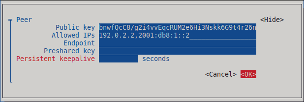
Select next to *IPv4 Configuration, and press Enter.
- Select the IPv4 configuration method Manual.
- Enter the tunnel IPv4 address and the subnet mask. Leave the Gateway field empty.
Select next to IPv6 Configuration, and press Enter.
- Select the IPv6 configuration method Manual.
-
Enter the tunnel IPv6 address and the subnet mask. Leave the
Gatewayfield empty.
Select , and press Enter

-
Enter the name of the connection and the virtual interface, such as
- In the window with the list of connections, select , and press Enter.
- In the NetworkManager TUI main window, select , and press Enter.
- If you use this host in a network with DHCP or Stateless Address Autoconfiguration (SLAAC), the connection can be vulnerable to being redirected. For details and mitigation steps, see Assigning a VPN connection to a dedicated routing table to prevent the connection from bypassing the tunnel.
Verification
Display the interface configuration of the
wg0device:# wg show wg0 interface: wg0 public key: UtjqCJ57DeAscYKRfp7cFGiQqdONRn69u249Fa4O6BE= private key: (hidden) listening port: 51820 peer: bnwfQcC8/g2i4vvEqcRUM2e6Hi3Nskk6G9t4r26nFVM= allowed ips: 192.0.2.2/32, 2001:db8:1::2/128To display the private key in the output, use the
WG_HIDE_KEYS=never wg show wg0command.Display the IP configuration of the
wg0device:# ip address show wg0 20: wg0: <POINTOPOINT,NOARP,UP,LOWER_UP> mtu 1420 qdisc noqueue state UNKNOWN group default qlen 1000 link/none inet 192.0.2.1/24 brd 192.0.2.255 scope global noprefixroute wg0 valid_lft forever preferred_lft forever inet6 _2001:db8:1::1/64 scope global noprefixroute valid_lft forever preferred_lft forever inet6 fe80::3ef:8863:1ce2:844/64 scope link noprefixroute valid_lft forever preferred_lft forever
7.7. Configuring a WireGuard server by using the RHEL web console
You can configure a WireGuard server by using the browser-based RHEL web console. Use this method to let NetworkManager manage the WireGuard connection.
Prerequisites
- You are logged in to the RHEL web console.
You know the following information:
- The static tunnel IP addresses and subnet masks of both the server and client
- The public key of the client
Procedure
- Select the Networking tab in the navigation on the left side of the screen.
- Click Add VPN in the Interfaces section.
-
If the
wireguard-toolsandsystemd-resolvedpackages are not already installed, the web console displays a corresponding notification. Click Install to install these packages. - Enter the name of the WireGuard device that you want to create.
Configure the key pair of this host:
If you want use the keys that the web console has created:
- Keep the pre-selected Generated option in the Private key area.
- Note the Public key value. You require this information when you configure the client.
If you want to use an existing private key:
- Select Paste existing key in the Private key area.
- Paste the private key into the text field. The web console automatically calculates the corresponding public key.
Set a listen port number, such as
51820, for incoming WireGuard connections.Always set a fixed port number on hosts that receive incoming WireGuard connections. If you do not set a port, WireGuard uses a random free port each time you activate the interface.
Set the tunnel IPv4 address and subnet mask of the server.
To also set an IPv6 address, you must edit the connection after you have created it.
Add peer configurations for each client that you want to allow to communicate with this server:
- Click Add peer.
- Enter the public key of the client.
- Leave the Endpoint field empty.
- Set the Allowed IPs field to the tunnel IP addresses of the clients that are allowed to send data to this server.
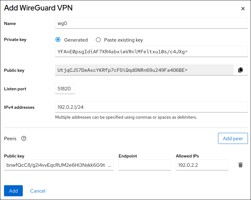
- Click Add to create the WireGuard connection.
If you want to also set a tunnel IPv6 address:
- Click on the WireGuard connection’s name in the Interfaces section.
- Click edit next to IPv6.
-
Set the Addresses field to
Manual, and enter the tunnel IPv6 address and prefix of the server. - Click Save.
- If you use this host in a network with DHCP or Stateless Address Autoconfiguration (SLAAC), the connection can be vulnerable to being redirected. For details and mitigation steps, see Assigning a VPN connection to a dedicated routing table to prevent the connection from bypassing the tunnel.
Verification
Display the interface configuration of the
wg0device:# wg show wg0 interface: wg0 public key: UtjqCJ57DeAscYKRfp7cFGiQqdONRn69u249Fa4O6BE= private key: (hidden) listening port: 51820 peer: bnwfQcC8/g2i4vvEqcRUM2e6Hi3Nskk6G9t4r26nFVM= allowed ips: 192.0.2.2/32, 2001:db8:1::2/128To display the private key in the output, use the
WG_HIDE_KEYS=never wg show wg0command.Display the IP configuration of the
wg0device:# ip address show wg0 20: wg0: <POINTOPOINT,NOARP,UP,LOWERUP> mtu 1420 qdisc noqueue state UNKNOWN group default qlen 1000 link/none inet 192.0.2.1/24 brd 192.0.2.255 scope global noprefixroute wg0 valid_lft forever preferred_lft forever inet6 2001:db8:1::1/32 scope global noprefixroute valid_lft forever preferred_lft forever inet6 fe80::3ef:8863:1ce2:844/64 scope link noprefixroute valid_lft forever preferred_lft forever
7.8. Configuring firewalld on a WireGuard server by using the command line
Configure the firewalld service on the WireGuard server, allowing incoming connections from clients. If clients need to use the server as their default gateway and route all traffic through the tunnel, enable also masquerading.
Procedure
Open the WireGuard port for incoming connections in the
firewalldservice:# firewall-cmd --permanent --add-port=51820/udp --zone=publicIf you want clients to route all traffic through the tunnel and use the WireGuard server as the default gateway, enable masquerading for the
publiczone:# firewall-cmd --permanent --zone=public --add-masqueradeReload the
firewalldrules.# firewall-cmd --reload
Verification
Display the configuration of the
publiczone:# firewall-cmd --list-all public (active) ... ports: 51820/udp masquerade: yes ...
7.9. Configuring firewalld on a WireGuard server by using the RHEL web console
Configure the firewalld service on the WireGuard server, allowing incoming connections from clients. If clients need to use the server as their default gateway and route all traffic through the tunnel, enable also masquerading.
Prerequisites
- You are logged in to the RHEL web console.
Procedure
- Select the Networking tab in the navigation on the left side of the screen.
- Click Edit rules and zones in the Firewall section.
- Click Add services.
-
Enter
wireguardinto the Filter services field. Select the
wireguardentry from the list.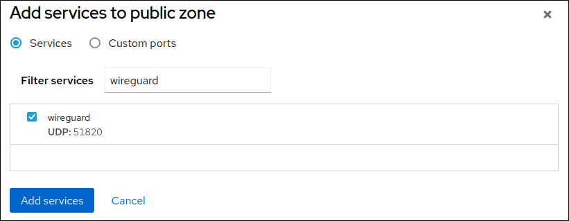
- Click Add services.
If you want clients to route all traffic through the tunnel and use the WireGuard server as the default gateway, enable masquerading for the
publiczone:# firewall-cmd --permanent --zone=public --add-masquerade # firewall-cmd --reloadNote that you cannot enable masquerading in
firewalldzones in the web console.
Verification
- Select the Networking tab in the navigation on the left side of the screen.
- Click Edit rules and zones in the Firewall section.
-
The list contains an entry for the
wireguardservice and displays the UDP port that you configured in the WireGuard connection profile. To verify that masquerading is enabled in the
publiczone offirewalld, enter:# firewall-cmd --list-all --zone=public public (active) ... services: ... wireguard ports: forward: yes masquerade: yes ...
7.10. Configuring a WireGuard client by using nmcli
You can configure a WireGuard client by creating a connection profile in NetworkManager. Use this method to let NetworkManager manage the WireGuard connection.
This procedure assumes the following settings:
Client:
-
Private key:
aPUcp5vHz8yMLrzk8SsDyYnV33IhE/k20e52iKJFV0A= -
Tunnel IPv4 address:
192.0.2.2/24 -
Tunnel IPv6 address:
2001:db8:1::2/64
-
Private key:
Server:
-
Public key:
UtjqCJ57DeAscYKRfp7cFGiQqdONRn69u249Fa4O6BE= -
Tunnel IPv4 address:
192.0.2.1/24 -
Tunnel IPv6 address:
2001:db8:1::1/64
-
Public key:
Prerequisites
- You have generated the public and private key for both the server and client.
You know the following information:
- The private key of the client
- The static tunnel IP addresses and subnet masks of the client
- The public key of the server
- The static tunnel IP addresses and subnet masks of the server
Procedure
Add a NetworkManager WireGuard connection profile:
# nmcli connection add type wireguard con-name client-wg0 ifname wg0This command creates a profile named
client-wg0and assigns the virtual interfacewg0to it.Optional: Configure NetworkManager so that it does not automatically start the
client-wgconnection:# nmcli connection modify client-wg0 autoconnect noSet the tunnel IPv4 address and subnet mask of the client:
# nmcli connection modify client-wg0 ipv4.method manual ipv4.addresses 192.0.2.2/24Set the tunnel IPv6 address and subnet mask of the client:
# nmcli connection modify client-wg0 ipv6.method manual ipv6.addresses 2001:db8:1::2/64If you want to route all traffic through the tunnel, set the tunnel IP addresses of the server as the default gateway:
# nmcli connection modify client-wg0 ipv4.gateway 192.0.2.1 ipv6.gateway 2001:db8:1::1Routing all traffic through the tunnel requires that you set, in a later step, the
allowed-ipson this client to0.0.0.0/0;::/0.Note that routing all traffic through the tunnel can impact the connectivity to other hosts based on the server routing and firewall configuration.
Add the client’s private key to the connection profile:
# nmcli connection modify client-wg0 wireguard.private-key "aPUcp5vHz8yMLrzk8SsDyYnV33IhE/k20e52iKJFV0A="Add peer connection configurations for each server that you want to allow to communicate with this client:
# nmcli connection modify client-wg0 wireguard.peers 'kEyMNyYhpmn9zPQ4m7iGmU9G7nooS9eeUBe0Y0wO0gM= endpoint=server.example.com:51820 allowed-ips=0.0.0.0/0 ;::/0'The
wireguard.peersparameter defines the peer section of the client in the NetworkManager connection profile. Use0.0.0.0/0;::/0;inallowed-ipsto allow any remote IPv4 and IPv6 address to communicate with this client. Use this setting to route all traffic through the tunnel and use the WireGuard server as default gateway.Reactivate the
client-wg0connection:# nmcli connection up client-wg0- If you use this host in a network with DHCP or Stateless Address Autoconfiguration (SLAAC), the connection can be vulnerable to being redirected. For details and mitigation steps, see Assigning a VPN connection to a dedicated routing table to prevent the connection from bypassing the tunnel.
Verification
Ping the IP addresses of the server:
# ping 192.0.2.1
# ping6 2001:db8:1::1
Display the interface configuration of the
wg0device:# wg show wg0 interface: wg0 public key: bnwfQcC8/g2i4vvEqcRUM2e6Hi3Nskk6G9t4r26nFVM= private key: (hidden) listening port: 51820 peer: UtjqCJ57DeAscYKRfp7cFGiQqdONRn69u249Fa4O6BE= endpoint: server.example.com:51820 allowed ips: 192.0.2.1/32, 2001:db8:1::1/128 latest handshake: 1 minute, 41 seconds ago transfer: 824 B received, 1.01 KiB sent persistent keepalive: every 20 secondsTo display the private key in the output, use the
WG_HIDE_KEYS=never wg show wg0command.Note that the output has only the
latest handshakeandtransferentries if you have already sent traffic through the VPN tunnel.Display the IP configuration of the
wg0device:# ip address show wg0 10: wg0: <POINTOPOINT,NOARP,UP,LOWER_UP> mtu 1420 qdisc noqueue state UNKNOWN group default qlen 1000 link/none inet 192.0.2.2/24 brd 192.0.2.255 scope global noprefixroute wg0 valid_lft forever preferred_lft forever inet6 2001:db8:1::2/64 scope global noprefixroute valid_lft forever preferred_lft forever inet6 fe80::73d9:6f51:ea6f:863e/64 scope link noprefixroute valid_lft forever preferred_lft forever
7.11. Configuring a WireGuard client by using nmtui
You can configure a WireGuard client by creating a connection profile in NetworkManager. Use this method to let NetworkManager manage the WireGuard connection.
This procedure assumes the following settings:
Client:
-
Private key:
aPUcp5vHz8yMLrzk8SsDyYnV33IhE/k20e52iKJFV0A= -
Tunnel IPv4 address:
192.0.2.2/24 -
Tunnel IPv6 address:
2001:db8:1::2/64
-
Private key:
Server:
-
Public key:
UtjqCJ57DeAscYKRfp7cFGiQqdONRn69u249Fa4O6BE= -
Tunnel IPv4 address:
192.0.2.1/24 -
Tunnel IPv6 address:
2001:db8:1::1/64
-
Public key:
Prerequisites
- You have generated the public and private key for both the server and client.
You know the following information:
- The private key of the client
- The static tunnel IP addresses and subnet masks of the client
- The public key of the server
- The static tunnel IP addresses and subnet masks of the server
-
You installed the
NetworkManager-tuipackage
Procedure
Start the
nmtuiapplication:# nmtui- Select Edit a connection, and press Enter.
- Select , and press Enter.
- Select the WireGuard connection type in the list, and press Enter.
In the Edit connection window:
-
Enter the name of the connection and the virtual interface, such as
wg0, that NetworkManager should assign to the connection. Enter the private key of the client.
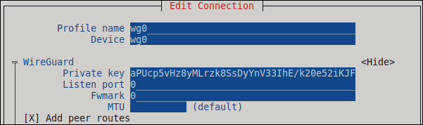
Click next to the Peers pane:
- Enter the public key of the server.
Set the Allowed IPs field. For example, set it to:
- The tunnel IP addresses of the server to allow only the server to communicate with this client.
-
0.0.0.0/0,::/0to allow any remote IPv4 and IPv6 address to communicate with this client. Use this setting to route all traffic through the tunnel and use the WireGuard server as default gateway.
-
Enter the host name or IP address and port of the WireGuard server into the Endpoint field. Use the following format:
<hostname_or_IP>:<port_number> - Optional: If you use the client in a network with network address translation (NAT) or if a firewall closes the UDP connection after some time of inactivity, set a persistent keepalive interval in seconds. In this interval, the client sends a keepalive packet to the server.
Select , and press Enter.
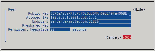
Select next to IPv4 Configuration, and press Enter.
- Select the IPv4 configuration method Manual.
- Enter the tunnel IPv4 address and the subnet mask. Leave the Gateway field empty.
Select next to IPv6 Configuration, and press Enter.
- Select the IPv6 configuration method Manual.
- Enter the tunnel IPv6 address and the subnet mask. Leave the Gateway field empty.
- Optional: Select Automatically connect.
Select , and press Enter

-
Enter the name of the connection and the virtual interface, such as
- In the window with the list of connections, select , and press Enter.
- In the NetworkManager TUI main window, select , and press Enter.
- If you use this host in a network with DHCP or Stateless Address Autoconfiguration (SLAAC), the connection can be vulnerable to being redirected. For details and mitigation steps, see Assigning a VPN connection to a dedicated routing table to prevent the connection from bypassing the tunnel.
Verification
Ping the IP addresses of the server:
# ping 192.0.2.1
# ping6 2001:db8:1::1
Display the interface configuration of the
wg0device:# wg show wg0 interface: wg0 public key: bnwfQcC8/g2i4vvEqcRUM2e6Hi3Nskk6G9t4r26nFVM= private key: (hidden) listening port: 51820 peer: UtjqCJ57DeAscYKRfp7cFGiQqdONRn69u249Fa4O6BE= endpoint: server.example.com:51820_ allowed ips: 192.0.2.1/32, 2001:db8:1::1/128 latest handshake: 1 minute, 41 seconds ago transfer: 824 B received, 1.01 KiB sent persistent keepalive: every 20 secondsTo display the private key in the output, use the
WG_HIDE_KEYS=never wg show wg0command.Note that the output contains only the
latest handshakeandtransferentries if you have already sent traffic through the VPN tunnel.Display the IP configuration of the
wg0device:# ip address show wg0 10: wg0: <POINTOPOINT,NOARP,UP,LOWER_UP> mtu 1420 qdisc noqueue state UNKNOWN group default qlen 1000 link/none inet 192.0.2.2/24 brd 192.0.2.255 scope global noprefixroute wg0 valid_lft forever preferred_lft forever inet6 2001:db8:1::2/64 scope global noprefixroute valid_lft forever preferred_lft forever inet6 fe80::73d9:6f51:ea6f:863e/64 scope link noprefixroute valid_lft forever preferred_lft forever
7.12. Configuring a WireGuard client by using the RHEL web console
You can configure a WireGuard client by using the browser-based RHEL web console. Use this method to let NetworkManager manage the WireGuard connection.
Prerequisites
- You are logged in to the RHEL web console.
You know the following information:
- The static tunnel IP addresses and subnet masks of both the server and client
- The public key of the server
Procedure
- Select the Networking tab in the navigation on the left side of the screen.
- Click Add VPN in the Interfaces section.
-
If the
wireguard-toolsandsystemd-resolvedpackages are not already installed, the web console displays a corresponding notification. Click Install to install these packages. - Enter the name of the WireGuard device that you want to create.
Configure the key pair of this host:
If you want use the keys that the web console has created:
- Keep the pre-selected Generated option in the Private key area.
- Note the Public key value. You require this information when you configure the client.
If you want to use an existing private key:
- Select Paste existing key in the Private key area.
- Paste the private key into the text field. The web console automatically calculates the corresponding public key.
-
Preserve the
0value in the Listen port field. Set the tunnel IPv4 address and subnet mask of the client.
To also set an IPv6 address, you must edit the connection after you have created it.
Add a peer configuration for the server that you want to allow to communicate with this client:
- Click Add peer.
- Enter the public key of the server.
-
Set the Endpoint field to the hostname or IP address and the port of the server, for example
server.example.com:51820. The client uses this information to establish the connection. Set the Allowed IPs field to the tunnel IP addresses of the clients that are allowed to send data to this server. For example, set the field to one of the following:
- The tunnel IP addresses of the server to allow only the server to communicate with this client. The value in the screen capture below configures this scenario.
-
0.0.0.0/0to allow any remote IPv4 address to communicate with this client. Use this setting to route all traffic through the tunnel and use the WireGuard server as default gateway.

- Click Add to create the WireGuard connection.
If you want to also set a tunnel IPv6 address:
- Click on the WireGuard connection’s name in the Interfaces section.
- Click Edit next to IPv6.
-
Set the Addresses field to
Manual, and enter the tunnel IPv6 address and prefix of the client. - Click Save.
- If you use this host in a network with DHCP or Stateless Address Autoconfiguration (SLAAC), the connection can be vulnerable to being redirected. For details and mitigation steps, see Assigning a VPN connection to a dedicated routing table to prevent the connection from bypassing the tunnel.
Verification
Ping the IP addresses of the server:
# ping 192.0.2.1WireGuard establishes the connection when you try to send traffic through the tunnel.
Display the interface configuration of the
wg0device:# wg show wg0 interface: wg0 public key: bnwfQcC8/g2i4vvEqcRUM2e6Hi3Nskk6G9t4r26nFVM= private key: (hidden) listening port: 45513 peer: UtjqCJ57DeAscYKRfp7cFGiQqdONRn69u249Fa4O6BE= endpoint: server.example.com:51820 allowed ips: 192.0.2.1/32, 2001:db8:1::1/128 latest handshake: 1 minute, 41 seconds ago transfer: 824 B received, 1.01 KiB sent persistent keepalive: every 20 secondsTo display the private key in the output, use the
WG_HIDE_KEYS=never wg show wg0command.Note that the output has only the
latest handshakeandtransferentries if you have already sent traffic through the VPN tunnel.Display the IP configuration of the
wg0device:# ip address show wg0 10: wg0: <POINTOPOINT,NOARP,UP,LOWERUP> mtu 1420 qdisc noqueue state UNKNOWN group default qlen 1000 link/none inet 192.0.2.2/24 brd 192.0.2.255 scope global noprefixroute wg0 valid_lft forever preferred_lft forever inet6 2001:db8:1::2/32 scope global noprefixroute valid_lft forever preferred_lft forever inet6 fe80::73d9:6f51:ea6f:863e/64 scope link noprefixroute valid_lft forever preferred_lft forever
7.13. Assigning a VPN connection to a dedicated routing table to prevent the connection from bypassing the tunnel
To protect your VPN connection from traffic redirection attacks, assign it to a dedicated routing table. This prevents malicious network servers from bypassing the secure tunnel and compromising data integrity.
Both a DHCP server and Stateless Address Autoconfiguration (SLAAC) can add routes to a client’s routing table. For example, a malicious DHCP server can use this feature to force a host with VPN connection to redirect traffic through a physical interface instead of the VPN tunnel. This vulnerability is also known as TunnelVision and described in the CVE-2024-3661 vulnerability article.
To mitigate this vulnerability, you can assign the VPN connection to a dedicated routing table. This prevents the DHCP configuration or SLAAC from manipulating routing decisions for network packets intended for the VPN tunnel.
Follow the steps if at least one of the conditions applies to your environment:
- At least one network interface uses DHCP or SLAAC.
- Your network does not use mechanisms, such as DHCP snooping, that prevent a rogue DHCP server.
Routing the entire traffic through the VPN prevents the host from accessing local network resources.
Procedure
- Decide which routing table you want to use. The following steps use table 75. By default, RHEL does not use the tables 1-254, and you can use any of them.
Configure the VPN connection profile to place the VPN routes in a dedicated routing table:
# nmcli connection modify <vpn_connection_profile> ipv4.route-table 75 ipv6.route-table 75Set a low priority value for the table you used in the previous command:
# nmcli connection modify <vpn_connection_profile> ipv4.routing-rules "priority 32345 from all table 75" ipv6.routing-rules "priority 32345 from all table 75"The priority value can be any value between 1 and 32766. The lower the value, the higher the priority.
Reconnect the VPN connection:
# nmcli connection down <vpn_connection_profile> # nmcli connection up <vpn_connection_profile>
Verification
Display the IPv4 routes in table 75:
# ip route show table 75 ... 192.0.2.0/24 via 192.0.2.254 dev vpn_device proto static metric 50 default dev vpn_device proto static scope link metric 50The output confirms that both the route to the remote network and the default gateway are assigned to routing table 75 and, therefore, all traffic is routed through the tunnel. If you set
ipv4.never-default truein the VPN connection profile, a default route is not created and, therefore, not visible in this output.Display the IPv6 routes in table 75:
# ip -6 route show table 75 ... 2001:db8:1::/64 dev vpn_device proto kernel metric 50 pref medium default dev vpn_device proto static metric 50 pref mediumThe output confirms that both the route to the remote network and the default gateway are assigned to routing table 75 and, therefore, all traffic is routed through the tunnel. If you set
ipv6.never-default truein the VPN connection profile, a default route is not created and, therefore, not visible in this output.
Chapter 8. Configuring IP tunnels
Similar to a VPN, an IP tunnel directly connects two networks over a third network, such as the internet. However, not all tunnel protocols support encryption.
The routers in both networks that establish the tunnel requires at least two interfaces:
- One interface that is connected to the local network
- One interface that is connected to the network through which the tunnel is established.
To establish the tunnel, you create a virtual interface on both routers with an IP address from the remote subnet.
NetworkManager supports the following IP tunnels:
- Generic Routing Encapsulation (GRE)
- Generic Routing Encapsulation over IPv6 (IP6GRE)
- Generic Routing Encapsulation Terminal Access Point (GRETAP)
- Generic Routing Encapsulation Terminal Access Point over IPv6 (IP6GRETAP)
- IPv4 over IPv4 (IPIP)
- IPv4 over IPv6 (IPIP6)
- IPv6 over IPv6 (IP6IP6)
- Simple Internet Transition (SIT)
Depending on the type, these tunnels act either on layer 2 or 3 of the Open Systems Interconnection (OSI) model.
8.1. Configuring an IPIP tunnel to encapsulate IPv4 traffic in IPv4 packets
An IP over IP (IPIP) tunnel operates on OSI layer 3 and encapsulates IPv4 traffic in IPv4 packets.
Data sent through an IPIP tunnel is not encrypted. For security reasons, use the tunnel only for data that is already encrypted, for example, by other protocols, such as HTTPS.
Note that IPIP tunnels support only unicast packets. If you require an IPv4 tunnel that supports multicast, see Configuring a GRE tunnel using nmcli to encapsulate layer-3 traffic in IPv4 packets.
For example, you can create an IPIP tunnel between two RHEL routers to connect two internal subnets over the internet as shown in the following diagram:

Prerequisites
- Each RHEL router has a network interface that is connected to its local subnet.
- Each RHEL router has a network interface that is connected to the internet.
- The traffic you want to send through the tunnel is IPv4 unicast.
Procedure
On the RHEL router in network A:
Create an IPIP tunnel interface named
tun0:# nmcli connection add type ip-tunnel ip-tunnel.mode ipip con-name tun0 ifname tun0 remote 198.51.100.5 local 203.0.113.10The
remoteandlocalparameters set the public IP addresses of the remote and the local routers.Set the IPv4 address to the
tun0device:# nmcli connection modify tun0 ipv4.addresses '10.0.1.1/30'Note that a
/30subnet with two usable IP addresses is sufficient for the tunnel.Configure the
tun0connection to use a manual IPv4 configuration:# nmcli connection modify tun0 ipv4.method manualAdd a static route that routes traffic to the
172.16.0.0/24network to the tunnel IP on router B:# nmcli connection modify tun0 +ipv4.routes "172.16.0.0/24 10.0.1.2"Enable the
tun0connection.# nmcli connection up tun0Enable packet forwarding:
# echo "net.ipv4.ip_forward=1" > /etc/sysctl.d/95-IPv4-forwarding.conf # sysctl -p /etc/sysctl.d/95-IPv4-forwarding.conf
On the RHEL router in network B:
Create an IPIP tunnel interface named
tun0:# nmcli connection add type ip-tunnel ip-tunnel.mode ipip con-name tun0 ifname tun0 remote 203.0.113.10 local 198.51.100.5The
remoteandlocalparameters set the public IP addresses of the remote and local routers.Set the IPv4 address to the
tun0device:# nmcli connection modify tun0 ipv4.addresses '10.0.1.2/30'Configure the
tun0connection to use a manual IPv4 configuration:# nmcli connection modify tun0 ipv4.method manualAdd a static route that routes traffic to the
192.0.2.0/24network to the tunnel IP on router A:# nmcli connection modify tun0 +ipv4.routes "192.0.2.0/24 10.0.1.1"Enable the
tun0connection.# nmcli connection up tun0Enable packet forwarding:
# echo "net.ipv4.ip_forward=1" > /etc/sysctl.d/95-IPv4-forwarding.conf # sysctl -p /etc/sysctl.d/95-IPv4-forwarding.conf
Verification
From each RHEL router, ping the IP address of the internal interface of the other router:
On Router A, ping
172.16.0.1:# ping 172.16.0.1On Router B, ping
192.0.2.1:# ping 192.0.2.1
8.2. Configuring a GRE tunnel to encapsulate layer-3 traffic in IPv4 packets
A Generic Routing Encapsulation (GRE) tunnel encapsulates layer-3 traffic in IPv4 packets. A GRE tunnel can encapsulate any layer 3 protocol with a valid Ethernet type.
Data sent through a GRE tunnel is not encrypted. For security reasons, use the tunnel only for data that is already encrypted, for example, by other protocols, such as HTTPS.
For example, you can create a GRE tunnel between two RHEL routers to connect two internal subnets over the internet as shown in the following diagram:

Prerequisites
- Each RHEL router has a network interface that is connected to its local subnet.
- Each RHEL router has a network interface that is connected to the internet.
Procedure
On the RHEL router in network A:
Create a GRE tunnel interface named
gre1:# nmcli connection add type ip-tunnel ip-tunnel.mode gre con-name gre1 ifname gre1 remote 198.51.100.5 local 203.0.113.10The
remoteandlocalparameters set the public IP addresses of the remote and the local routers.ImportantThe
gre0device name is reserved. Usegre1or a different name for the device.Set the IPv4 address to the
gre1device:# nmcli connection modify gre1 ipv4.addresses '10.0.1.1/30'Note that a
/30subnet with two usable IP addresses is sufficient for the tunnel.Configure the
gre1connection to use a manual IPv4 configuration:# nmcli connection modify gre1 ipv4.method manualAdd a static route that routes traffic to the
172.16.0.0/24network to the tunnel IP on router B:# nmcli connection modify gre1 +ipv4.routes "172.16.0.0/24 10.0.1.2"Enable the
gre1connection.# nmcli connection up gre1Enable packet forwarding:
# echo "net.ipv4.ip_forward=1" > /etc/sysctl.d/95-IPv4-forwarding.conf # sysctl -p /etc/sysctl.d/95-IPv4-forwarding.conf
On the RHEL router in network B:
Create a GRE tunnel interface named
gre1:# nmcli connection add type ip-tunnel ip-tunnel.mode gre con-name gre1 ifname gre1 remote 203.0.113.10 local 198.51.100.5The
remoteandlocalparameters set the public IP addresses of the remote and the local routers.Set the IPv4 address to the
gre1device:# nmcli connection modify gre1 ipv4.addresses '10.0.1.2/30'Configure the
gre1connection to use a manual IPv4 configuration:# nmcli connection modify gre1 ipv4.method manualAdd a static route that routes traffic to the
192.0.2.0/24network to the tunnel IP on router A:# nmcli connection modify gre1 +ipv4.routes "192.0.2.0/24 10.0.1.1"Enable the
gre1connection.# nmcli connection up gre1Enable packet forwarding:
# echo "net.ipv4.ip_forward=1" > /etc/sysctl.d/95-IPv4-forwarding.conf # sysctl -p /etc/sysctl.d/95-IPv4-forwarding.conf
Verification
From each RHEL router, ping the IP address of the internal interface of the other router:
On Router A, ping
172.16.0.1:# ping 172.16.0.1On Router B, ping
192.0.2.1:# ping 192.0.2.1
8.3. Configuring a GRETAP tunnel to transfer Ethernet frames over IPv4
A Generic Routing Encapsulation Terminal Access Point (GRETAP) tunnel operates on OSI level 2 and encapsulates Ethernet traffic in IPv4 packets.
Data sent through a GRETAP tunnel is not encrypted. For security reasons, establish the tunnel over a VPN or a different encrypted connection.
For example, you can create a GRETAP tunnel between two RHEL routers to connect two networks using a bridge as shown in the following diagram:

Prerequisites
- Each RHEL router has a network interface that is connected to its local network, and the interface has no IP configuration assigned.
- Each RHEL router has a network interface that is connected to the internet.
Procedure
On the RHEL router in network A:
Create a bridge interface named
bridge0:# nmcli connection add type bridge con-name bridge0 ifname bridge0Configure the IP settings of the bridge:
# nmcli connection modify bridge0 ipv4.addresses '192.0.2.1/24' # nmcli connection modify bridge0 ipv4.method manualAdd a new connection profile for the interface that is connected to local network to the bridge:
# nmcli connection add type ethernet port-type bridge con-name bridge0-port1 ifname enp1s0 controller bridge0Add a new connection profile for the GRETAP tunnel interface to the bridge:
# nmcli connection add type ip-tunnel ip-tunnel.mode gretap port-type bridge con-name bridge0-port2 ifname gretap1 remote 198.51.100.5 local 203.0.113.10 controller bridge0The
remoteandlocalparameters set the public IP addresses of the remote and the local routers.ImportantThe
gretap0device name is reserved. Usegretap1or a different name for the device.Optional: Disable the Spanning Tree Protocol (STP) if you do not need it:
# nmcli connection modify bridge0 bridge.stp noBy default, STP is enabled and causes a delay before you can use the connection.
Configure that activating the
bridge0connection automatically activates the ports of the bridge:# nmcli connection modify bridge0 connection.autoconnect-ports 1Active the
bridge0connection:# nmcli connection up bridge0
On the RHEL router in network B:
Create a bridge interface named
bridge0:# nmcli connection add type bridge con-name bridge0 ifname bridge0Configure the IP settings of the bridge:
# nmcli connection modify bridge0 ipv4.addresses '192.0.2.2/24' # nmcli connection modify bridge0 ipv4.method manualAdd a new connection profile for the interface that is connected to local network to the bridge:
# nmcli connection add type ethernet port-type bridge con-name bridge0-port1 ifname enp1s0 controller bridge0Add a new connection profile for the GRETAP tunnel interface to the bridge:
# nmcli connection add type ip-tunnel ip-tunnel.mode gretap port-type bridge con-name bridge0-port2 ifname gretap1 remote 203.0.113.10 local 198.51.100.5 controller bridge0The
remoteandlocalparameters set the public IP addresses of the remote and the local routers.Optional: Disable the Spanning Tree Protocol (STP) if you do not need it:
# nmcli connection modify bridge0 bridge.stp noConfigure that activating the
bridge0connection automatically activates the ports of the bridge:# nmcli connection modify bridge0 connection.autoconnect-ports 1Active the
bridge0connection:# nmcli connection up bridge0
Verification
On both routers, verify that the
enp1s0andgretap1connections are connected and that theCONNECTIONcolumn displays the connection name of the port:# nmcli device nmcli device DEVICE TYPE STATE CONNECTION ... bridge0 bridge connected bridge0 enp1s0 ethernet connected bridge0-port1 gretap1 iptunnel connected bridge0-port2From each RHEL router, ping the IP address of the internal interface of the other router:
On Router A, ping
192.0.2.2:# ping 192.0.2.2On Router B, ping
192.0.2.1:# ping 192.0.2.1
Chapter 9. Managing wifi connections
If your host contains a wifi adapter, you can connect it to a wifi network.
RHEL provides multiple utilities and applications to configure and connect to wifi networks, for example:
-
Use the
nmcliutility to configure connections by using the command line. -
Use the
nmtuiapplication to configure connections in a text-based user interface. -
Use the
GNOME Settingsapplication to configure connections by using the GNOME application. -
Use the
networkRHEL system role to automate the configuration of connections on one or multiple hosts.
9.1. Supported wifi security types
Depending on the security type a wifi network supports, you can transmit data more or less securely.
Do not connect to wifi networks that do not use encryption or which support only the insecure WPA standard.
Red Hat Enterprise Linux supports the following wifi security types:
-
None: Encryption is disabled, and data is transferred in plain text over the network. -
Enhanced Open: With opportunistic wireless encryption (OWE), devices negotiate unique pairwise master keys (PMK) to encrypt connections in wireless networks without authentication. -
LEAP: The Lightweight Extensible Authentication Protocol, which was developed by Cisco, is a proprietary version of the extensible authentication protocol (EAP). -
WPA & WPA2 Personal: In personal mode, the Wi-Fi Protected Access (WPA) and Wi-Fi Protected Access 2 (WPA2) authentication methods use a pre-shared key. -
WPA & WPA2 Enterprise: In enterprise mode, WPA and WPA2 use the EAP framework and authenticate users to a remote authentication dial-in user service (RADIUS) server. -
WPA3 Personal: Wi-Fi Protected Access 3 (WPA3) Personal uses simultaneous authentication of equals (SAE) instead of pre-shared keys (PSK) to prevent dictionary attacks. WPA3 uses perfect forward secrecy (PFS).
9.2. Connecting to a wifi network by using nmcli
When you first use the nmcli utility to connect to a wifi network, it automatically creates a NetworkManager connection profile. You can then modify this profile to add specific settings, such as a static IP address.
Prerequisites
- A wifi device is installed on the host.
-
The wifi device is enabled. To verify, use the
nmcli radiocommand.
Procedure
If the wifi radio has been disabled in NetworkManager, enable this feature:
# nmcli radio wifi onOptional: Display the available wifi networks:
# nmcli device wifi list IN-USE BSSID SSID MODE CHAN RATE SIGNAL BARS SECURITY 00:53:00:2F:3B:08 Office Infra 44 270 Mbit/s 57 ▂▄▆_ WPA2 WPA3 00:53:00:15:03:BF -- Infra 1 130 Mbit/s 48 ▂▄__ WPA2 WPA3The service set identifier (
SSID) column contains the names of the networks. If the column shows--, the access point of this network does not broadcast an SSID.Connect to the wifi network:
# nmcli device wifi connect Office --ask Password: wifi-passwordIf you prefer to set the password in the command instead of entering it interactively, use the
password <wifi_password>option in the command instead of--ask:# nmcli device wifi connect Office password <wifi_password>Note that, if the network requires static IP addresses, NetworkManager fails to activate the connection at this point. You can configure the IP addresses in later steps.
If the network requires static IP addresses:
Configure the IPv4 address settings, for example:
# nmcli connection modify Office ipv4.method manual ipv4.addresses 192.0.2.1/24 ipv4.gateway 192.0.2.254 ipv4.dns 192.0.2.200 ipv4.dns-search example.comConfigure the IPv6 address settings, for example:
# nmcli connection modify Office ipv6.method manual ipv6.addresses 2001:db8:1::1/64 ipv6.gateway 2001:db8:1::fffe ipv6.dns 2001:db8:1::ffbb ipv6.dns-search example.com
Re-activate the connection:
# nmcli connection up Office
Verification
Display the active connections:
# nmcli connection show --active NAME ID TYPE DEVICE Office 2501eb7e-7b16-4dc6-97ef-7cc460139a58 wifi wlp0s20f3If the output lists the wifi connection you have created, the connection is active.
Ping a hostname or IP address:
# ping -c 3 example.com
9.3. Connecting to a wifi network by using GNOME Settings
You can use the GNOME Settings application, also named gnome-control-center, to connect to a wifi network and configure the connection. When you connect to the network for the first time, GNOME creates a NetworkManager connection profile for it.
In GNOME Settings, you can configure wifi connections for all wifi network security types that RHEL supports.
Prerequisites
- A wifi device is installed on the host.
-
The wifi device is enabled. To verify, use the
nmcli radiocommand.
Procedure
-
Press the Super key, type
Wi-Fi, and press Enter. - Click the name of the wifi network you want to connect to.
-
Enter the password for the network, and click
Connect. If the network requires additional settings, such as static IP addresses or a security type other than WPA2 Personal:
- Click the gear icon next to the network’s name.
Optional: Configure the network profile on the
Detailstab to not automatically connect.If you deactivate this feature, you must always manually connect to the network, for example, by using GNOME Settings or the GNOME system menu.
-
Configure IPv4 settings on the
IPv4tab, and IPv6 settings on theIPv6tab. On the
Securitytab, select the authentication of the network, such asWPA3 Personal, and enter the password.Depending on the selected security, the application shows additional fields. Fill them accordingly. For details, ask the administrator of the wifi network.
-
Click
Apply.
Verification
Open the system menu on the right side of the top bar, and verify that the wifi network is connected:

If the network is listed, it is connected.
Ping a hostname or IP address:
# ping -c 3 example.com
9.4. Configuring a wifi connection by using nmtui
The nmtui application provides a text-based user interface for NetworkManager. You can use nmtui to connect to a wifi network.
In nmtui:
- Navigate by using the cursor keys.
- Press a button by selecting it and hitting Enter.
- Select and clear checkboxes by using Space.
- To return to the previous screen, use ESC.
Procedure
Start
nmtui:# nmtui-
Select
Edit a connection, and press Enter. -
Press the
Addbutton. -
Select
Wi-Fifrom the list of network types, and press Enter. Optional: Enter a name for the NetworkManager profile to be created.
On hosts with multiple profiles, a meaningful name makes it easier to identify the purpose of a profile.
-
Enter the name of the Wi-Fi network, the Service Set Identifier (SSID), into the
SSIDfield. -
Leave the
Modefield set to its default,Client. Select the
Securityfield, press Enter, and set the authentication type of the network from the list.Depending on the authentication type you have selected,
nmtuidisplays different fields.- Fill the authentication type-related fields.
If the Wi-Fi network requires static IP addresses:
-
Press the
Automaticbutton next to the protocol, and selectManualfrom the displayed list. -
Press the
Showbutton next to the protocol you want to configure to display additional fields, and fill them.
-
Press the
-
Press the
OKbutton to create and automatically activate the new connection. -
Press the
Backbutton to return to the main menu. -
Select
Quit, and press Enter to close thenmtuiapplication.
Verification
Open nmtui:
# nmcli connection show --active NAME ID TYPE DEVICE Office 2501eb7e-7b16-4dc6-97ef-7cc460139a58 wifi wlp0s20f3If the output lists the wifi connection you have created, the connection is active.
Ping a hostname or IP address:
# ping -c 3 example.com
9.5. Configuring a wifi connection with 802.1X network authentication in an existing profile by using nmcli
You can use the nmcli utility to configure a client to authenticate itself to a network.
For example, you can configure Protected Extensible Authentication Protocol (PEAP) authentication with Microsoft Challenge-Handshake Authentication Protocol version 2 (MSCHAPv2) in an existing NetworkManager wifi profile.
Prerequisites
- The network must have 802.1X network authentication.
- The wifi connection profile exists in NetworkManager and has a valid IP configuration.
-
If the client is required to verify the certificate of the authenticator, the Certificate Authority (CA) certificate must be stored in the
/etc/pki/ca-trust/source/anchors/directory. -
The
wpa_supplicantpackage is installed.
Procedure
Set the wifi security mode to
wpa-eap, the Extensible Authentication Protocol (EAP) topeap, the inner authentication protocol tomschapv2, and the user name:# nmcli connection modify wlp1s0 wireless-security.key-mgmt wpa-eap 802-1x.eap peap 802-1x.phase2-auth mschapv2 802-1x.identity <user_name>Note that you must set the
wireless-security.key-mgmt,802-1x.eap,802-1x.phase2-auth, and802-1x.identityparameters in a single command.Optional: Store the password in the configuration:
# nmcli connection modify wlp1s0 802-1x.password <password>ImportantBy default, NetworkManager stores the password in plain text in the
/etc/sysconfig/network-scripts/keys-connection_namefile, which is readable only by therootuser. However, plain text passwords in a configuration file can be a security risk.To increase the security, set the
802-1x.password-flagsparameter toagent-owned. With this setting, on servers with the GNOME desktop environment or thenm-appletrunning, NetworkManager retrieves the password from these services, after you unlock the keyring first. In other cases, NetworkManager prompts for the password.If the client needs to verify the certificate of the authenticator, set the
802-1x.ca-certparameter in the connection profile to the path of the CA certificate:# nmcli connection modify wlp1s0 802-1x.ca-cert /etc/pki/ca-trust/source/anchors/ca.crtNoteValidating the certificate of the authenticator improves the security.
Activate the connection profile:
# nmcli connection up wlp1s0
Verification
- Access resources on the network that require network authentication.
9.6. Configuring a wifi connection with 802.1X network authentication by using the network RHEL system role
By using the network RHEL system role, you can automate setting up Network Access Control (NAC) on remote hosts. You can define authentication details for clients in a playbook to ensure only authorized clients can access the network.
You can use an Ansible playbook to copy a private key, a certificate, and the CA certificate to the client, and then use the network RHEL system role to configure a connection profile with 802.1X network authentication.
Prerequisites
- You have prepared the control node and the managed nodes.
- You are logged in to the control node as a user who can run playbooks on the managed nodes.
-
The account you use to connect to the managed nodes has
sudopermissions for these nodes. - The network supports 802.1X network authentication.
-
You installed the
wpa_supplicantpackage on the managed node. - DHCP is available in the network of the managed node.
The following files required for TLS authentication exist on the control node:
-
The client key is stored in the
/srv/data/client.keyfile. -
The client certificate is stored in the
/srv/data/client.crtfile. -
The CA certificate is stored in the
/srv/data/ca.crtfile.
-
The client key is stored in the
Procedure
Store your sensitive variables in an encrypted file:
Create the vault:
$ ansible-vault create ~/vault.yml New Vault password: <vault_password> Confirm New Vault password: <vault_password>After the
ansible-vault createcommand opens an editor, enter the sensitive data in the<key>: <value>format:pwd: <password>- Save the changes, and close the editor. Ansible encrypts the data in the vault.
Create a playbook file, for example,
~/playbook.yml, with the following content:--- - name: Configure a wifi connection with 802.1X authentication hosts: managed-node-01.example.com vars_files: - ~/vault.yml tasks: - name: Copy client key for 802.1X authentication ansible.builtin.copy: src: "/srv/data/client.key" dest: "/etc/pki/tls/private/client.key" mode: 0400 - name: Copy client certificate for 802.1X authentication ansible.builtin.copy: src: "/srv/data/client.crt" dest: "/etc/pki/tls/certs/client.crt" - name: Copy CA certificate for 802.1X authentication ansible.builtin.copy: src: "/srv/data/ca.crt" dest: "/etc/pki/ca-trust/source/anchors/ca.crt" - name: Wifi connection profile with dynamic IP address settings and 802.1X ansible.builtin.import_role: name: redhat.rhel_system_roles.network vars: network_connections: - name: Wifi connection profile with dynamic IP address settings and 802.1X interface_name: wlp1s0 state: up type: wireless autoconnect: yes ip: dhcp4: true auto6: true wireless: ssid: "Example-wifi" key_mgmt: "wpa-eap" ieee802_1x: identity: <user_name> eap: tls private_key: "/etc/pki/tls/private/client.key" private_key_password: "{{ pwd }}" private_key_password_flags: none client_cert: "/etc/pki/tls/certs/client.crt" ca_cert: "/etc/pki/ca-trust/source/anchors/ca.crt" domain_suffix_match: "example.com" network_allow_restart: trueThe settings specified in the example playbook include the following:
ieee802_1x- This variable contains the 802.1X-related settings.
eap: tls-
Configures the profile to use the certificate-based
TLSauthentication method for the Extensible Authentication Protocol (EAP).
For details about all variables used in the playbook, see the
/usr/share/ansible/roles/rhel-system-roles.network/README.mdfile on the control node.Validate the playbook syntax:
$ ansible-playbook --ask-vault-pass --syntax-check ~/playbook.ymlNote that this command only validates the syntax and does not protect against a wrong but valid configuration.
Run the playbook:
$ ansible-playbook --ask-vault-pass ~/playbook.yml
9.7. Manually setting the wireless regulatory domain
On RHEL, a udev rule starts the setregdomain utility to set the wireless regulatory domain. The utility then provides this information to the kernel.
By default, setregdomain attempts to determine the country code automatically. If this fails, the wireless regulatory domain setting might be wrong. To work around this problem, you can manually set the country code.
Manually setting the regulatory domain disables the automatic detection. Therefore, if you later use the computer in a different country, the previously configured setting might no longer be correct. In this case, remove the /etc/sysconfig/regdomain file to switch back to automatic detection or use this procedure to manually update the regulatory domain setting again.
Prerequisites
- The driver of the wifi device supports changing the regulatory domain.
Procedure
Optional: Display the current regulatory domain settings:
# iw reg get global country US: DFS-FCC ...Create the
/etc/sysconfig/regdomainfile with the following content:COUNTRY=<country_code>Set the
COUNTRYvariable to an ISO 3166-1 alpha2 country code, such asDEfor Germany orUSfor the United States of America.Set the regulatory domain:
# setregdomain
Verification
Display the regulatory domain settings:
# iw reg get global country DE: DFS-ETSI ...
Chapter 10. Configuring a persistent qeth device on IBM Z
Channel-based network interfaces on the IBM Z platform are virtualized and not automatically visible to RHEL when attached to your logical partition (LPAR) or z/VM guest. Before you can use the device in a network configuration, you must manually group subchannels into a single logical qeth device and activate it.
Prerequisites
- You defined the I/O subchannels and attached them to your LPAR or z/VM guest.
-
You installed the
s390utils-basepackage.
Procedure
Unmask the device IDs of the
qethdevice:If you know the device IDs, unmask these IDs. For example:
# cio_ignore --remove 0.0.0600,0.0.0601,0.0.0602Specify the device IDs comma-separated as shown or as a range, for example
0.0.0600-0.0.0602.If you do not know the device IDs, you can unmask all IDs:
# cio_ignore --remove-all
Display the available
qethdevices:# lszdev qethTYPE ID ON PERS NAMES qeth 0.0.0600:0.0.0601:0.0.0602 no noThe output contains the following columns:
-
TYPE: Displays the device type. If you ranlszdev qeth, the command returns onlyqethdevices. -
ID: Displays the subchannel addresses of the hardware. This is a triplet of three hexadecimal addresses used for read, write, and data transfers. -
ON: Indicates the current operational state of the device wherenomeans that the driver has not yet grouped the channels and created a functional network device. -
PERS: Indicates the persistence status of the configuration wherenoconfirms that noudevdevice manager rule exists and, therefore, the device is not automatically be enabled after a reboot. -
NAMES: Displays the network interface name you can use in NetworkManager. If the field is empty, the channels have not been grouped or set online yet.
-
Create a
udevrule and activate theqethdevice:# chzdev qeth 0.0.0600 -eYou can specify only the first address of a triplet, and the
chzdevutility automatically detects the associated write and data channels.
Verification
Verify the hardware state, and display the assigned interface name:
# lszdev qeth TYPE ID ON PERS NAMES qeth 0.0.0600:0.0.0601:0.0.0602 yes yes enc600Ensure that both the
ONandPERScolumn returnyesfor your device. Note the interface name displayed in theNAMEScolumn. You require the name when you create a network configuration that uses this device.
Next steps
-
Use the
qethdevice in a network configuration, such as an Ethernet connection.
Chapter 11. Using MACsec to encrypt layer-2 traffic in the same physical network
Configure MACsec to encrypt Layer 2 traffic within the same physical network. This helps secure point-to-point communication between directly connected devices, such as hosts or switches.
11.1. How MACsec increases security
Use Media Access Control security (MACsec) to encrypt and authenticate LAN traffic at layer 2. This process helps eliminate the need to encrypt individual services at layer 7.
Media Access Control security secures point-to-point communication between devices. For example, you can configure MACsec on the two hosts connecting your branch and central offices over a Metro-Ethernet connection to increase security.
MACsec is a layer-2 protocol that encrypts and authenticates all LAN traffic. It uses a pre-shared key to establish connections. To change this key, you must update the NetworkManager configuration on all hosts that use MACsec.
MACsec secures different traffic types over the Ethernet links, including:
- Dynamic host configuration protocol (DHCP)
- address resolution protocol (ARP)
- IPv4 and IPv6 traffic
- Any traffic over IP such as TCP or UDP
A MACsec connection uses an Ethernet device, such as an Ethernet network card, Virtual Local Area Network (VLAN), or tunnel device, as a parent. You can either set an IP configuration only on the MACsec device to communicate with other hosts only by using the encrypted connection, or you can also set an IP configuration on the parent device. In the latter case, you can use the parent device to communicate with other hosts using an unencrypted connection and the MACsec device for encrypted connections.
MACsec does not require any special hardware. For example, you can use any switch, except if you want to encrypt traffic only between a host and a switch. In this scenario, the switch must also support MACsec.
That is, you can configure MACsec for two common scenarios:
- Host-to-host
- Host-to-switch and switch-to-other-hosts
You can use MACsec only between hosts being in the same physical or virtual LAN.
Using the MACsec security standard for securing communication at the link layer, also known as layer 2 of the Open Systems Interconnection (OSI) model provides the following notable benefits:
- Encryption at layer 2 eliminates the need for encrypting individual services at layer 7. This reduces the overhead associated with managing a large number of certificates for each endpoint on each host.
- Point-to-point security between directly connected network devices such as routers and switches.
- No changes needed for applications and higher-layer protocols.
11.2. Configuring a MACsec connection by using nmcli
You can use the nmcli utility to configure Ethernet interfaces to use MACsec. For example, you can create a MACsec connection between two hosts that are connected over Ethernet.
Procedure
On the first host on which you configure MACsec:
Create the connectivity association key (CAK) and connectivity-association key name (CKN) for the pre-shared key:
Create a 16-byte hexadecimal CAK:
# dd if=/dev/urandom count=16 bs=1 2> /dev/null | hexdump -e '1/2 "%04x"' 50b71a8ef0bd5751ea76de6d6c98c03aCreate a 32-byte hexadecimal CKN:
# dd if=/dev/urandom count=32 bs=1 2> /dev/null | hexdump -e '1/2 "%04x"' f2b4297d39da7330910a74abc0449feb45b5c0b9fc23df1430e1898fcf1c4550
- On both hosts you want to connect over a MACsec connection:
Create the MACsec connection:
# nmcli connection add type macsec con-name macsec0 ifname macsec0 connection.autoconnect yes macsec.parent enp1s0 macsec.mode psk macsec.mka-cak 50b71a8ef0bd5751ea76de6d6c98c03a macsec.mka-ckn f2b4297d39da7330910a74abc0449feb45b5c0b9fc23df1430e1898fcf1c4550Use the CAK and CKN generated in the previous step in the
macsec.mka-cakandmacsec.mka-cknparameters. The values must be the same on every host in the MACsec-protected network.Configure the IP settings on the MACsec connection.
Configure the
IPv4settings. For example, to set a staticIPv4address, network mask, default gateway, and DNS server to themacsec0connection, enter:# nmcli connection modify macsec0 ipv4.method manual ipv4.addresses '192.0.2.1/24' ipv4.gateway '192.0.2.254' ipv4.dns '192.0.2.253'Configure the
IPv6settings. For example, to set a staticIPv6address, network mask, default gateway, and DNS server to themacsec0connection, enter:# nmcli connection modify macsec0 ipv6.method manual ipv6.addresses '2001:db8:1::1/32' ipv6.gateway '2001:db8:1::fffe' ipv6.dns '2001:db8:1::fffd'
Activate the connection:
# nmcli connection up macsec0
Verification
Verify that the traffic is encrypted:
# tcpdump -nn -i enp1s0Optional: Display the unencrypted traffic:
# tcpdump -nn -i macsec0Display MACsec statistics:
# ip macsec showDisplay individual counters for each type of protection: integrity-only (encrypt off) and encryption (encrypt on)
# ip -s macsec show
11.3. Configuring a MACsec connection by using nmstatectl
You can use the declarative Nmstate API to configure Ethernet interfaces to use MACsec. Nmstate ensures that the result matches the configuration file or rolls back the changes.
Prerequisites
- A physical or virtual Ethernet Network Interface Controller (NIC) exists in the server configuration.
-
The
nmstatepackage is installed.
Procedure
On the first host on which you configure MACsec, create the connectivity association key (CAK) and connectivity-association key name (CKN) for the pre-shared key:
Create a 16-byte hexadecimal CAK:
# dd if=/dev/urandom count=16 bs=1 2> /dev/null | hexdump -e '1/2 "%04x"' 50b71a8ef0bd5751ea76de6d6c98c03aCreate a 32-byte hexadecimal CKN:
# dd if=/dev/urandom count=32 bs=1 2> /dev/null | hexdump -e '1/2 "%04x"' f2b4297d39da7330910a74abc0449feb45b5c0b9fc23df1430e1898fcf1c4550
On both hosts that you want to connect over a MACsec connection, complete the following steps:
Create a YAML file, for example
create-macsec-connection.yml, with the following settings:--- routes: config: - destination: 0.0.0.0/0 next-hop-interface: macsec0 next-hop-address: 192.0.2.2 table-id: 254 - destination: 192.0.2.2/32 next-hop-interface: macsec0 next-hop-address: 0.0.0.0 table-id: 254 dns-resolver: config: search: - example.com server: - 192.0.2.200 - 2001:db8:1::ffbb interfaces: - name: macsec0 type: macsec state: up ipv4: enabled: true address: - ip: 192.0.2.1 prefix-length: 32 ipv6: enabled: true address: - ip: 2001:db8:1::1 prefix-length: 64 macsec: encrypt: true base-iface: enp0s1 mka-cak: 50b71a8ef0bd5751ea76de6d6c98c03a mka-ckn: f2b4297d39da7330910a74abc0449feb45b5c0b9fc23df1430e1898fcf1c4550 port: 0 validation: strict send-sci: true-
Use the CAK and CKN generated in the previous step in the
mka-cakandmka-cknparameters. The values must be the same on every host in the MACsec-protected network. Optional: In the same YAML configuration file, you can also configure the following settings:
-
A static IPv4 address -
192.0.2.1with the/32subnet mask -
A static IPv6 address -
2001:db8:1::1with the/64subnet mask -
An IPv4 default gateway -
192.0.2.2 -
An IPv4 DNS server -
192.0.2.200 -
An IPv6 DNS server -
2001:db8:1::ffbb -
A DNS search domain -
example.com
-
A static IPv4 address -
Apply the settings to the system:
# nmstatectl apply create-macsec-connection.yml
Verification
Display the current state in YAML format:
# nmstatectl show macsec0Verify that the traffic is encrypted:
# tcpdump -nn -i enp0s1Optional: Display the unencrypted traffic:
# tcpdump -nn -i macsec0Display MACsec statistics:
# ip macsec showDisplay individual counters for each type of protection: integrity-only (encrypt off) and encryption (encrypt on)
# ip -s macsec show
Chapter 12. Configuring NetworkManager to ignore certain devices
By default, NetworkManager manages all devices except the ones described in the /usr/lib/udev/rules.d/85-nm-unmanaged.rules file. To ignore certain other devices, you can configure them in NetworkManager as unmanaged.
12.1. Permanently configuring a device as unmanaged in NetworkManager
You can set devices as unmanaged based on criteria, such as interface name or MAC address. If you use a device section for this, NetworkManager does not manage the device until you include it in a connection profile.
Procedure
Optional: Display the list of devices to identify the device or MAC address you want to set as
unmanaged:# ip link show ... 2: enp1s0: <BROADCAST,MULTICAST,UP,LOWER_UP> mtu 1500 qdisc fq_codel state UP mode DEFAULT group default qlen 1000 link/ether 52:54:00:74:79:56 brd ff:ff:ff:ff:ff:ff ...-
Create a
*.conffile in the/etc/NetworkManager/conf.d/directory, for example,/etc/NetworkManager/conf.d/99-unmanaged-devices.conf. For each device you want to configure as unmanaged, add a section with a unique name to the file.
ImportantThe section name must begin with
device-.To configure a specific interface as unmanaged, add:
[device-enp1s0-unmanaged] match-device=interface-name:enp1s0 managed=0To configure a device with a specific MAC address as unmanaged, add:
[device-mac525400747956-unmanaged] match-device=mac:52:54:00:74:79:56 managed=0To configure all devices of a specific type as unmanaged, add:
[device-ethernet-unmanaged] match-device=type:ethernet managed=0To set multiple devices as unmanaged, separate the entries in the
unmanaged-devicesparameter with a semicolon, for example:[device-multiple-devices-unmanaged] match-device=interface-name:enp1s0;interface-name:enp7s0 managed=0Alternatively, you can add separate sections for each device in this file or create additional
*.conffiles in the/etc/NetworkManager/conf.d/directory.
Restart the host system:
# rebootThe reboot clears the state in the
/run/NetworkManager/devices/directory. This prevents that NetworkManager uses an existing connection from this directory for the device you set as unmanaged.
Verification
Display the list of devices:
# nmcli device status DEVICE TYPE STATE CONNECTION enp1s0 ethernet unmanaged -- ...The
unmanagedstate next to theenp1s0device indicates that NetworkManager does not manage this device.
Troubleshooting
If the output of the
nmcli device statuscommand does not list the device asunmanaged, display the NetworkManager configuration:# NetworkManager --print-config ... [device-enp1s0-unmanaged] match-device=interface-name:enp1s0 managed=0 ...If the output does not match the settings that you configured, ensure that no configuration file with a higher priority overrides your settings. For details on how NetworkManager merges multiple configuration files, see the
NetworkManager.conf(5)man page on your system.
12.2. Temporarily configuring a device as unmanaged in NetworkManager
You can temporarily configure devices as unmanaged, for example, for testing purposes. This change persists a reload and restart of the NetworkManager systemd service, but not a system reboot.
Procedure
Optional: Display the list of devices to identify the device you want to set as
unmanaged:# nmcli device status DEVICE TYPE STATE CONNECTION enp1s0 ethernet disconnected -- ...Set the
enp1s0device to theunmanagedstate:# nmcli device set enp1s0 managed no
Verification
Display the list of devices:
# nmcli device status DEVICE TYPE STATE CONNECTION enp1s0 ethernet unmanaged -- ...The
unmanagedstate next to theenp1s0device indicates that NetworkManager does not manage this device.
12.3. Identifying the reason why NetworkManager does not manage a certain network device
In addition to the status of each network device, NetworkManager also tracks the reason why the devices are in their current status. You can use this feature to identify why NetworkManager does not manage certain devices.
Procedure
Display the status and its reason of all network devices:
# nmcli -f GENERAL.DEVICE,GENERAL.STATE,GENERAL.REASON device showIf you pass a device name to the command, you can display the output only of the specified device.
Example output:
GENERAL.DEVICE: enp1s0 GENERAL.STATE: 10 (unmanaged) GENERAL.REASON: 75 (The device is unmanaged by explicit user decision (e.g. 'nmcli device set $DEV managed no')) GENERAL.DEVICE: enp7s0 GENERAL.STATE: 10 (unmanaged) GENERAL.REASON: 74 (The device is unmanaged by user decision in NetworkManager.conf ('unmanaged' in a [device*] section) GENERAL.DEVICE: veth3 GENERAL.STATE: 10 (unmanaged) GENERAL.REASON: 77 (The device is unmanaged via udev rule)NoteNote that the command returns the status of all devices, regardless whether they are managed or unmanaged.
Chapter 13. Managing the default gateway
The default gateway is a router that forwards network packets when no other route matches the destination of a packet. In a local network, the default gateway is typically the host that is one hop closer to the internet.
13.1. Setting the default gateway on an existing connection by using nmcli
In most situations, administrators set the default gateway when they create a connection. However, you can also set or update the default gateway setting on a previously created connection by using the nmcli utility.
Prerequisites
- At least one static IP address must be configured on the connection on which the default gateway will be set.
-
If the user is logged in on a physical console, user permissions are sufficient. Otherwise, the user must have
rootpermissions.
Procedure
Set the IP addresses of the default gateway:
To set the IPv4 default gateway, enter:
# nmcli connection modify <connection_name> ipv4.gateway "<IPv4_gateway_address>"To set the IPv6 default gateway, enter:
# nmcli connection modify <connection_name> ipv6.gateway "<IPv6_gateway_address>"Restart the network connection for changes to take effect:
# nmcli connection up <connection_name>WarningAll connections currently using this network connection are temporarily interrupted during the restart.
Verification
Verify that the route is active:
To display the IPv4 default gateway, enter:
# ip -4 route default via 192.0.2.1 dev example proto static metric 100To display the IPv6 default gateway, enter:
# ip -6 route default via 2001:db8:1::1 dev example proto static metric 100 pref medium
13.2. Setting the default gateway on an existing connection by using nmstatectl
You can use the declarative Nmstate API to set or update the default gateway in a connection. Nmstate ensures that the result matches the configuration file or rolls back the changes.
Prerequisites
- At least one static IP address must be configured on the connection on which the default gateway will be set.
-
The
enp1s0interface is configured, and the IP address of the default gateway is within the subnet of the IP configuration of this interface. -
The
nmstatepackage is installed.
Procedure
Create a YAML file, for example
~/set-default-gateway.yml, with the following content:--- routes: config: - destination: 0.0.0.0/0 next-hop-address: 192.0.2.1 next-hop-interface: enp1s0These settings define
192.0.2.1as the default gateway, and the default gateway is reachable through theenp1s0interface.Apply the settings to the system:
# nmstatectl apply ~/set-default-gateway.yml
13.3. Setting the default gateway on an existing connection by using the network RHEL system role
By using the network RHEL system role, you can automate setting the default gateway in a NetworkManager connection profile. With this method, you can remotely configure the default gateway on hosts defined in a playbook.
In most situations, administrators set the default gateway when they create a connection. However, you can also set or update the default gateway setting on a previously-created connection.
You cannot use the network RHEL system role to update only specific values in an existing connection profile. The role ensures that a connection profile exactly matches the settings in a playbook. If a connection profile with the same name already exists, the role applies the settings from the playbook and resets all other settings in the profile to their defaults. To prevent resetting values, always specify the whole configuration of the network connection profile in the playbook, including the settings that you do not want to change.
Prerequisites
- You have prepared the control node and the managed nodes.
- You are logged in to the control node as a user who can run playbooks on the managed nodes.
-
The account you use to connect to the managed nodes has
sudopermissions for these nodes.
Procedure
Create a playbook file, for example,
~/playbook.yml, with the following content:--- - name: Configure the network hosts: managed-node-01.example.com tasks: - name: Ethernet connection profile with static IP address settings ansible.builtin.include_role: name: redhat.rhel_system_roles.network vars: network_connections: - name: enp1s0 type: ethernet autoconnect: yes ip: address: - 198.51.100.20/24 - 2001:db8:1::1/64 gateway4: 198.51.100.254 gateway6: 2001:db8:1::fffe dns: - 198.51.100.200 - 2001:db8:1::ffbb dns_search: - example.com state: upFor details about all variables used in the playbook, see the
/usr/share/ansible/roles/rhel-system-roles.network/README.mdfile on the control node.Validate the playbook syntax:
$ ansible-playbook --syntax-check ~/playbook.ymlNote that this command only validates the syntax and does not protect against a wrong but valid configuration.
Run the playbook:
$ ansible-playbook ~/playbook.yml
Verification
Query the Ansible facts of the managed node and verify the active network settings:
# ansible managed-node-01.example.com -m ansible.builtin.setup ... "ansible_default_ipv4": { ... "gateway": "198.51.100.254", "interface": "enp1s0", ... }, "ansible_default_ipv6": { ... "gateway": "2001:db8:1::fffe", "interface": "enp1s0", ... } ...
13.4. How NetworkManager manages multiple default gateways
In certain situations, for example for fallback reasons, you set multiple default gateways on a host. However, to avoid asynchronous routing issues, each default gateway of the same protocol requires a separate metric value.
Note that RHEL only uses the connection to the default gateway that has the lowest metric set.
You can set the metric for both the IPv4 and IPv6 gateway of a connection using the following command:
# nmcli connection modify <connection_name> ipv4.route-metric <value> ipv6.route-metric <value>Do not set the same metric value for the same protocol in multiple connection profiles to avoid routing issues.
If you set a default gateway without a metric value, NetworkManager automatically sets the metric value based on the interface type. For that, NetworkManager assigns the default value of this network type to the first connection that is activated, and sets an incremented value to each other connection of the same type in the order they are activated. For example, if two Ethernet connections with a default gateway exist, NetworkManager sets a metric of 100 on the route to the default gateway of the connection that you activate first. For the second connection, NetworkManager sets 101.
The following is an overview of frequently-used network types and their default metrics:
| Connection type | Default metric value |
|---|---|
| VPN | 50 |
| Ethernet | 100 |
| MACsec | 125 |
| InfiniBand | 150 |
| Bond | 300 |
| VLAN | 400 |
| Bridge | 425 |
| TUN | 450 |
| Wi-Fi | 600 |
| IP tunnel | 675 |
13.5. Configuring NetworkManager to avoid using a specific profile to provide a default gateway
In connection profiles that are not connected to the default gateway, you can configure that NetworkManager never uses this profile to provide the default gateway.
Prerequisites
- The NetworkManager connection profile for the connection that is not connected to the default gateway exists.
Procedure
If the connection uses a dynamic IP configuration, configure that NetworkManager does not use this connection as the default connection for the corresponding IP type, meaning that NetworkManager never assigns the default route to it:
# nmcli connection modify <connection_name> ipv4.never-default yes ipv6.never-default yesNote that setting
ipv4.never-defaultandipv6.never-defaulttoyes, automatically removes the default gateway’s IP address for the corresponding protocol from the connection profile.Activate the connection:
# nmcli connection up <connection_name>
Verification
-
Use the
ip -4 routeandip -6 routecommands to verify that RHEL does not use the network interface for the default route for the IPv4 and IPv6 protocol.
13.6. Fixing unexpected routing behavior due to multiple default gateways
For most hosts, you require only a single default gateway to prevent unexpected routing behavior and asynchronous routing issues. Multiple default gateways are typically needed only for specific scenarios, such as when using Multipath TCP.
To route traffic to different internet providers, use policy-based routing instead of multiple default gateways.
Prerequisites
- The host uses NetworkManager to manage network connections, which is the default.
- The host has multiple network interfaces.
- The host has multiple default gateways configured.
Procedure
Display the routing table:
For IPv4, enter:
# ip -4 route default via 192.0.2.1 dev enp1s0 proto dhcp metric 101 default via 198.51.100.1 dev enp7s0 proto dhcp metric 102 ...For IPv6, enter:
# ip -6 route default via 2001:db8:1::1 dev enp1s0 proto ra metric 101 pref medium default via 2001:db8:2::1 dev enp7s0 proto ra metric 102 pref medium ...
Entries starting with
defaultindicate a default route. Note the interface names of these entries displayed next todev.Use the following commands to display the NetworkManager connections that use the interfaces you identified in the previous step:
# nmcli -f GENERAL.CONNECTION,IP4.GATEWAY,IP6.GATEWAY device show enp1s0 GENERAL.CONNECTION: Corporate-LAN IP4.GATEWAY: 192.0.2.1 IP6.GATEWAY: 2001:db8:1::1 # nmcli -f GENERAL.CONNECTION,IP4.GATEWAY,IP6.GATEWAY device show enp7s0 GENERAL.CONNECTION: Internet-Provider IP4.GATEWAY: 198.51.100.1 IP6.GATEWAY: 2001:db8:2::1In these examples, the profiles named
Corporate-LANandInternet-Providerhave the default gateways set. Because, in a local network, the default gateway is typically the host that is one hop closer to the internet, the rest of this procedure assumes that the default gateways in theCorporate-LANare incorrect.Configure that NetworkManager does not use the
Corporate-LANconnection as the default route for IPv4 and IPv6 connections:# nmcli connection modify Corporate-LAN ipv4.never-default yes ipv6.never-default yesNote that setting
ipv4.never-defaultandipv6.never-defaulttoyes, automatically removes the default gateway’s IP address for the corresponding protocol from the connection profile.Activate the
Corporate-LANconnection:# nmcli connection up Corporate-LAN
Verification
Display the IPv4 and IPv6 routing tables and verify that only one default gateway is available for each protocol:
For IPv4, enter:
# ip -4 route default via 198.51.100.1 dev enp7s0 proto dhcp metric 102 ...For IPv6, enter:
# ip -6 route default via 2001:db8:2::1 dev enp7s0 proto ra metric 102 pref medium ...
Chapter 14. Configuring a static route
Routing directs traffic between mutually-connected networks. In larger environments, administrators configure services so that routers dynamically learn about each other. In smaller ones, administrators often configure static routes to ensure traffic can reach its destination.
You need static routes to achieve a functioning communication among multiple networks if all of these conditions apply:
- The traffic has to pass multiple networks.
- The exclusive traffic flow through the default gateways is not sufficient.
14.1. Example of a network that requires static routes
You require static routes in this example because not all IP networks are directly connected through one router. Without the static routes, some networks cannot communicate with each other. Additionally, traffic from some networks flows only in one direction.
The network topology in this example is artificial and only used to explain the concept of static routing. It is not a recommended topology in production environments.
For a functioning communication among all networks in this example, configure a static route to Raleigh (198.51.100.0/24) with next the hop Router 2 (203.0.113.10). The IP address of the next hop is the one of Router 2 in the data center network (203.0.113.0/24).
You can configure the static route as follows:
-
For a simplified configuration, set this static route only on Router 1. However, this increases the traffic on Router 1 because hosts from the data center (
203.0.113.0/24) send traffic to Raleigh (198.51.100.0/24) always through Router 1 to Router 2. -
For a more complex configuration, configure this static route on all hosts in the data center (
203.0.113.0/24). All hosts in this subnet then send traffic directly to Router 2 (203.0.113.10) that is closer to Raleigh (198.51.100.0/24).
For more details between which networks traffic flows or not, see the explanations following the diagram.
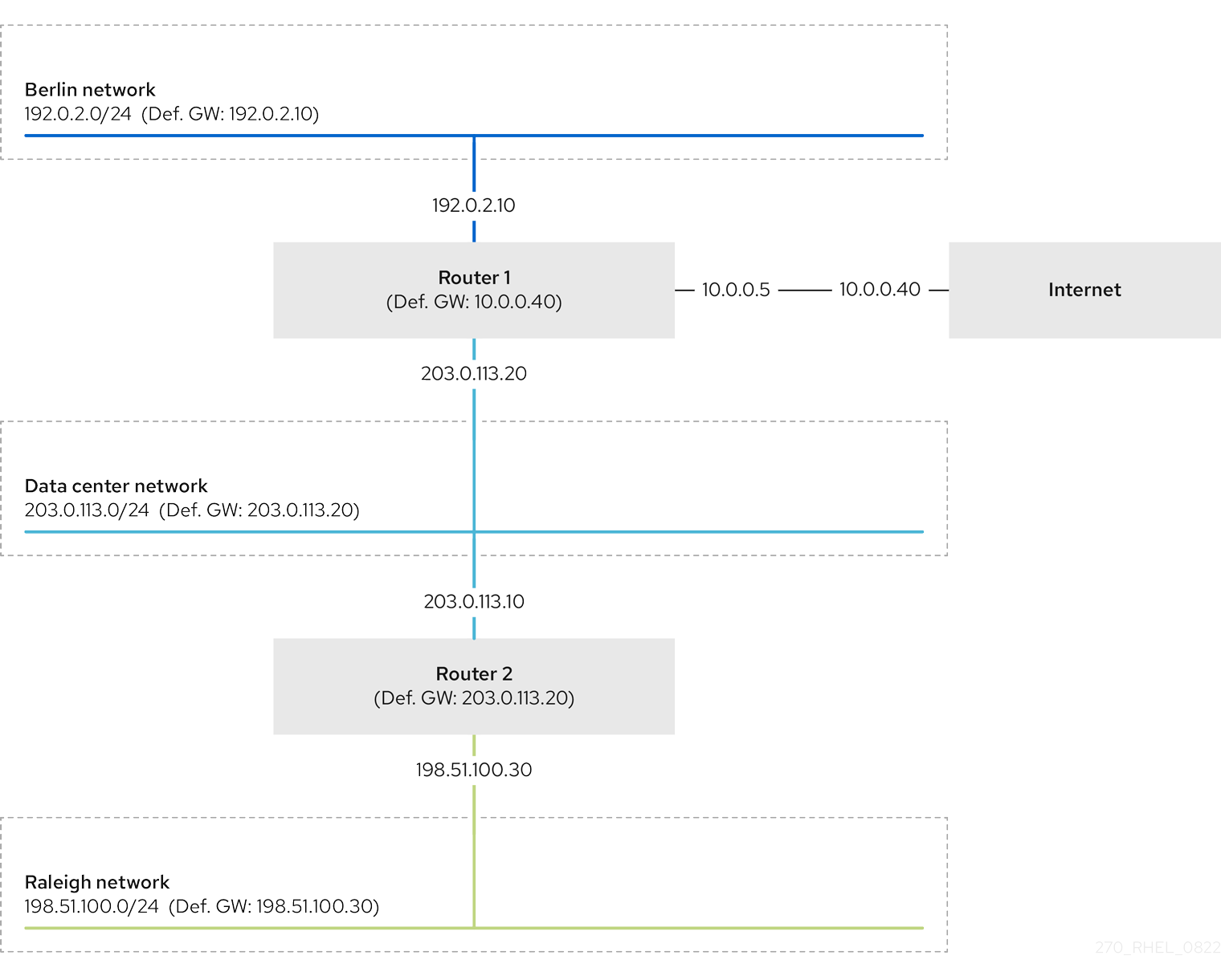
In case that the required static routes are not configured, the following are the situations in which the communication works and when it does not:
Hosts in the Berlin network (
192.0.2.0/24):- Can communicate with other hosts in the same subnet because they are directly connected.
-
Can communicate with the internet because Router 1 is in the Berlin network (
192.0.2.0/24) and has a default gateway, which leads to the internet. -
Can communicate with the data center network (
203.0.113.0/24) because Router 1 has interfaces in both the Berlin (192.0.2.0/24) and the data center (203.0.113.0/24) networks. -
Cannot communicate with the Raleigh network (
198.51.100.0/24) because Router 1 has no interface in this network. Therefore, Router 1 sends the traffic to its own default gateway (internet).
Hosts in the data center network (
203.0.113.0/24):- Can communicate with other hosts in the same subnet because they are directly connected.
-
Can communicate with the internet because they have their default gateway set to Router 1, and Router 1 has interfaces in both networks, the data center (
203.0.113.0/24) and to the internet. -
Can communicate with the Berlin network (
192.0.2.0/24) because they have their default gateway set to Router 1, and Router 1 has interfaces in both the data center (203.0.113.0/24) and the Berlin (192.0.2.0/24) networks. -
Cannot communicate with the Raleigh network (
198.51.100.0/24) because the data center network has no interface in this network. Therefore, hosts in the data center (203.0.113.0/24) send traffic to their default gateway (Router 1). Router 1 also has no interface in the Raleigh network (198.51.100.0/24) and, as a result, Router 1 sends this traffic to its own default gateway (internet).
Hosts in the Raleigh network (
198.51.100.0/24):- Can communicate with other hosts in the same subnet because they are directly connected.
-
Cannot communicate with hosts on the internet. Router 2 sends the traffic to Router 1 because of the default gateway settings. The actual behavior of Router 1 depends on the reverse path filter (
rp_filter) system control (sysctl) setting. By default on RHEL, Router 1 drops the outgoing traffic instead of routing it to the internet. However, regardless of the configured behavior, communication is not possible without the static route. -
Cannot communicate with the data center network (
203.0.113.0/24). The outgoing traffic reaches the destination through Router 2 because of the default gateway setting. However, replies to packets do not reach the sender because hosts in the data center network (203.0.113.0/24) send replies to their default gateway (Router 1). Router 1 then sends the traffic to the internet. -
Cannot communicate with the Berlin network (
192.0.2.0/24). Router 2 sends the traffic to Router 1 because of the default gateway settings. The actual behavior of Router 1 depends on thesysctlsettingrp_filter. By default on RHEL, Router 1 drops the outgoing traffic instead of sending it to the Berlin network (192.0.2.0/24). However, regardless of the configured behavior, communication is not possible without the static route.
In addition to configuring the static routes, you must enable IP forwarding on both routers.
14.2. How to use the nmcli utility to configure a static route
You can use the nmcli utility to configure a static route on the command line.
Use following syntax:
$ nmcli connection modify connection_name ipv4.routes "ip[/prefix] [next_hop] [metric] [attribute=value] [attribute=value] ..."The command supports the following route attributes:
-
cwnd=n: Sets the congestion window (CWND) size, defined in the number of packets. -
lock-cwnd=true|false: Defines whether or not the kernel can update the CWND value. -
lock-mtu=true|false: Defines whether or not the kernel can update the MTU to path MTU discovery. -
lock-window=true|false: Defines whether or not the kernel can update the maximum window size for TCP packets. -
mtu=<mtu_value>: Sets the maximum transfer unit (MTU) to use along the path to the destination. -
onlink=true|false: Defines whether the next hop is directly attached to this link even if it does not match any interface prefix. -
scope=<scope>: For an IPv4 route, this attribute sets the scope of the destinations covered by the route prefix. Set the value as an integer (0-255). -
src=<source_address>: Sets the source address to prefer when sending traffic to the destinations covered by the route prefix. -
table=<table_id>: Sets the ID of the table the route should be added to. If you omit this parameter, NetworkManager uses themaintable. -
tos=<type_of_service_key>: Sets the type of service (TOS) key. Set the value as an integer (0-255). -
type=<route_type>: Sets the route type. NetworkManager supports theunicast,local,blackhole,unreachable,prohibit, andthrowroute types. The default isunicast. -
window=<window_size>: Sets the maximal window size for TCP to advertise to these destinations, measured in bytes.
If you use the ipv4.routes option without a preceding + sign, nmcli overrides all current settings of this parameter.
To create an additional route, enter:
$ nmcli connection modify connection_name +ipv4.routes "<route>"To remove a specific route, enter:
$ nmcli connection modify connection_name -ipv4.routes "<route>"
14.3. Configuring a static route by using nmcli
You can add a static route to an existing NetworkManager connection profile using the nmcli connection modify command.
The procedure below configures the following routes:
-
An IPv4 route to the remote
198.51.100.0/24network. The corresponding gateway with the IP address192.0.2.10is reachable through theLANconnection profile. -
An IPv6 route to the remote
2001:db8:2::/64network. The corresponding gateway with the IP address2001:db8:1::10is reachable through theLANconnection profile.
Prerequisites
-
The
LANconnection profile exists and it configures this host to be in the same IP subnet as the gateways.
Procedure
Add the static IPv4 route to the
LANconnection profile:# nmcli connection modify LAN +ipv4.routes "198.51.100.0/24 192.0.2.10"To set multiple routes in one step, pass the individual routes comma-separated to the command:
# nmcli connection modify <connection_profile> +ipv4.routes "<remote_network_1>/<subnet_mask_1> <gateway_1>, <remote_network_n>/<subnet_mask_n> <gateway_n>, ..."Add the static IPv6 route to the
LANconnection profile:# nmcli connection modify LAN +ipv6.routes "2001:db8:2::/64 2001:db8:1::10"Re-activate the connection:
# nmcli connection up LAN
Verification
Display the IPv4 routes:
# ip -4 route ... 198.51.100.0/24 via 192.0.2.10 dev enp1s0Display the IPv6 routes:
# ip -6 route ... 2001:db8:2::/64 via 2001:db8:1::10 dev enp1s0 metric 1024 pref medium
14.4. Configuring a static route by using nmtui
The nmtui application provides a text-based user interface for NetworkManager. You can use nmtui to configure static routes on a host without a graphical interface.
For example, the procedure below adds a route to the 192.0.2.0/24 network that uses the gateway running on 198.51.100.1, which is reachable through an existing connection profile.
In nmtui:
- Navigate by using the cursor keys.
- Press a button by selecting it and hitting Enter.
- Select and clear checkboxes by using Space.
- To return to the previous screen, use ESC.
Prerequisites
- The network is configured.
- The gateway for the static route must be directly reachable on the interface.
- If the user is logged in on a physical console, user permissions are sufficient. Otherwise, the command requires root permissions.
Procedure
Start
nmtui:# nmtui- Select Edit a connection, and press Enter.
- Select the connection profile through which you can reach the next hop to the destination network, and press Enter.
- Depending on whether it is an IPv4 or IPv6 route, press the Show button next to the protocol’s configuration area.
Press the Edit button next to Routing. This opens a new window where you configure static routes:
Press the Add button and fill in:
- The destination network, including the prefix in Classless Inter-Domain Routing (CIDR) format
- The IP address of the next hop
- A metric value, if you add multiple routes to the same network and want to prioritize the routes by efficiency
- Repeat the previous step for every route you want to add and that is reachable through this connection profile.
Press the OK button to return to the window with the connection settings.
Figure 14.1. Example of a static route without metric
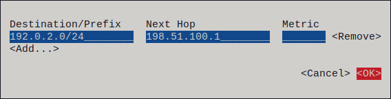
-
Press the OK button to return to the
nmtuimain menu. - Select Activate a connection and press Enter.
Select the connection profile that you edited, and press Enter twice to deactivate and activate it again.
ImportantSkip this step if you run
nmtuiover a remote connection, such as SSH, that uses the connection profile you want to reactivate. In this case, if you deactivate it innmtui, the connection is terminated and, consequently, you cannot activate it again. To avoid this problem, use thenmcli connection <connection_profile> upcommand to reactivate the connection in the mentioned scenario.- Press the Back button to return to the main menu.
-
Select Quit, and press Enter to close the
nmtuiapplication.
Verification
Verify that the route is active:
$ ip route ... 192.0.2.0/24 via 198.51.100.1 dev example proto static metric 100
14.5. Configuring a static route by using nmstatectl
You can use the declarative Nmstate API to configure a static route. Nmstate ensures that the result matches the configuration file or rolls back the changes.
Prerequisites
-
The
enp1s0network interface is configured and is in the same IP subnet as the gateways. -
The
nmstatepackage is installed.
Procedure
Create a YAML file, for example
~/add-static-route-to-enp1s0.yml, with the following content:--- routes: config: - destination: 198.51.100.0/24 next-hop-address: 192.0.2.10 next-hop-interface: enp1s0 - destination: 2001:db8:2::/64 next-hop-address: 2001:db8:1::10 next-hop-interface: enp1s0These settings define the following static routes:
-
An IPv4 route to the remote
198.51.100.0/24network. The corresponding gateway with the IP address192.0.2.10is reachable through theenp1s0interface. -
An IPv6 route to the remote
2001:db8:2::/64network. The corresponding gateway with the IP address2001:db8:1::10is reachable through theenp1s0interface.
-
An IPv4 route to the remote
Apply the settings to the system:
# nmstatectl apply ~/add-static-route-to-enp1s0.yml
Verification
Display the IPv4 routes:
# ip -4 route ... 198.51.100.0/24 via 192.0.2.10 dev enp1s0Display the IPv6 routes:
# ip -6 route ... 2001:db8:2::/64 via 2001:db8:1::10 dev enp1s0 metric 1024 pref medium
14.6. Configuring a static route by using the network RHEL system role
You can use the network RHEL system role to configure static routes.
When you run a play that uses the network RHEL system role and if the setting values do not match the values specified in the play, the role overrides the existing connection profile with the same name. To prevent resetting these values to their defaults, always specify the whole configuration of the network connection profile in the play, even if the configuration, for example the IP configuration, already exists.
Prerequisites
- You have prepared the control node and the managed nodes.
- You are logged in to the control node as a user who can run playbooks on the managed nodes.
-
The account you use to connect to the managed nodes has
sudopermissions for these nodes.
Procedure
Create a playbook file, for example,
~/playbook.yml, with the following content:--- - name: Configure the network hosts: managed-node-01.example.com tasks: - name: Configure an Ethernet connection with static IP and additional routes ansible.builtin.include_role: name: redhat.rhel_system_roles.network vars: network_connections: - name: enp7s0 type: ethernet autoconnect: yes ip: address: - 192.0.2.1/24 - 2001:db8:1::1/64 gateway4: 192.0.2.254 gateway6: 2001:db8:1::fffe dns: - 192.0.2.200 - 2001:db8:1::ffbb dns_search: - example.com route: route: - network: 198.51.100.0 prefix: 24 gateway: 192.0.2.10 - network: '2001:db8:2::' prefix: 64 gateway: 2001:db8:1::10 state: upDepending on whether it already exists, the procedure creates or updates the
enp7s0connection profile with the following settings:-
A static IPv4 address -
192.0.2.1with a/24subnet mask -
A static IPv6 address -
2001:db8:1::1with a/64subnet mask -
An IPv4 default gateway -
192.0.2.254 -
An IPv6 default gateway -
2001:db8:1::fffe -
An IPv4 DNS server -
192.0.2.200 -
An IPv6 DNS server -
2001:db8:1::ffbb -
A DNS search domain -
example.com Static routes:
-
198.51.100.0/24with gateway192.0.2.10 -
2001:db8:2::/64with gateway2001:db8:1::10
-
-
A static IPv4 address -
Validate the playbook syntax:
$ ansible-playbook --syntax-check ~/playbook.ymlNote that this command only validates the syntax and does not protect against a wrong but valid configuration.
Run the playbook:
$ ansible-playbook ~/playbook.yml
Verification
On the managed nodes:
Display the IPv4 routes:
# ip -4 route ... 198.51.100.0/24 via 192.0.2.10 dev enp7s0Display the IPv6 routes:
# ip -6 route ... 2001:db8:2::/64 via 2001:db8:1::10 dev enp7s0 metric 1024 pref medium
Chapter 15. Configuring policy-based routing to define alternative routes
By default, the RHEL kernel forwards network packets based on the destination address by using a routing table. With policy-based routing, you can configure complex scenarios to route packets based on various criteria, such as the source address.
15.1. Routing traffic from a specific subnet to a different default gateway by using nmcli
You can use policy-based routing to configure a different default gateway for traffic from certain subnets.
For example, you can configure RHEL as a router that, by default, routes all traffic to internet provider A using the default route. However, traffic received from the internal workstations subnet is routed to provider B.
The procedure assumes the following network topology:

Prerequisites
-
The system uses
NetworkManagerto configure the network, which is the default. The RHEL router you want to set up in the procedure has four network interfaces:
-
The
enp7s0interface is connected to the network of provider A. The gateway IP in the provider’s network is198.51.100.2, and the network uses a/30network mask. -
The
enp1s0interface is connected to the network of provider B. The gateway IP in the provider’s network is192.0.2.2, and the network uses a/30network mask. -
The
enp8s0interface is connected to the10.0.0.0/24subnet with internal workstations. -
The
enp9s0interface is connected to the203.0.113.0/24subnet with the company’s servers.
-
The
-
Hosts in the internal workstations subnet use
10.0.0.1as the default gateway. In the procedure, you assign this IP address to theenp8s0network interface of the router. -
Hosts in the server subnet use
203.0.113.1as the default gateway. In the procedure, you assign this IP address to theenp9s0network interface of the router. -
The
firewalldservice is enabled and active.
Procedure
Configure the network interface to provider A:
# nmcli connection add type ethernet con-name Provider-A ifname enp7s0 ipv4.method manual ipv4.addresses 198.51.100.1/30 ipv4.gateway 198.51.100.2 ipv4.dns 198.51.100.200 connection.zone externalThe
nmcli connection addcommand creates a NetworkManager connection profile. The command uses the following options:-
type ethernet: Defines that the connection type is Ethernet. -
con-name <connection_name>: Sets the name of the profile. Use a meaningful name to avoid confusion. -
ifname <network_device>: Sets the network interface. -
ipv4.method manual: Enables to configure a static IP address. -
ipv4.addresses <IP_address>/<subnet_mask>: Sets the IPv4 addresses and subnet mask. -
ipv4.gateway <IP_address>: Sets the default gateway address. -
ipv4.dns <IP_of_DNS_server>: Sets the IPv4 address of the DNS server. -
connection.zone <firewalld_zone>: Assigns the network interface to the definedfirewalldzone. Note thatfirewalldautomatically enables masquerading for interfaces assigned to theexternalzone.
-
Configure the network interface to provider B:
# nmcli connection add type ethernet con-name Provider-B ifname enp1s0 ipv4.method manual ipv4.addresses 192.0.2.1/30 ipv4.routes "0.0.0.0/0 192.0.2.2 table=5000" connection.zone externalThis command uses the
ipv4.routesparameter instead ofipv4.gatewayto set the default gateway. This is required to assign the default gateway for this connection to a different routing table (5000) than the default. NetworkManager automatically creates this new routing table when the connection is activated.Configure the network interface to the internal workstations subnet:
# nmcli connection add type ethernet con-name Internal-Workstations ifname enp8s0 ipv4.method manual ipv4.addresses 10.0.0.1/24 ipv4.routes "10.0.0.0/24 table=5000" ipv4.routing-rules "priority 5 from 10.0.0.0/24 table 5000" connection.zone trustedThis command uses the
ipv4.routesparameter to add a static route to the routing table with ID5000. This static route for the10.0.0.0/24subnet uses the IP of the local network interface to provider B (192.0.2.1) as the next hop.Additionally, the command uses the
ipv4.routing-rulesparameter to add a routing rule with priority5that routes traffic from the10.0.0.0/24subnet to table5000. Low values have a high priority.Note that the syntax in the
ipv4.routing-rulesparameter is the same as in anip rule addcommand, except thatipv4.routing-rulesalways requires specifying a priority.Configure the network interface to the server subnet:
# nmcli connection add type ethernet con-name Servers ifname enp9s0 ipv4.method manual ipv4.addresses 203.0.113.1/24 connection.zone trusted
Verification
On a RHEL host in the internal workstation subnet:
Install the
traceroutepackage:# dnf install tracerouteUse the
tracerouteutility to display the route to a host on the internet:# traceroute redhat.com traceroute to redhat.com (209.132.183.105), 30 hops max, 60 byte packets 1 _gateway (10.0.0.1) 0.337 ms 0.260 ms 0.223 ms 2 192.0.2.2 (192.0.2.2) 0.884 ms 1.066 ms 1.248 ms ...The output of the command displays that the router sends packets over
192.0.2.1, which is the network of provider B.
On a RHEL host in the server subnet:
Install the
traceroutepackage:# dnf install tracerouteUse the
tracerouteutility to display the route to a host on the internet:# traceroute redhat.com traceroute to redhat.com (209.132.183.105), 30 hops max, 60 byte packets 1 _gateway (203.0.113.1) 2.179 ms 2.073 ms 1.944 ms 2 198.51.100.2 (198.51.100.2) 1.868 ms 1.798 ms 1.549 ms ...The output of the command displays that the router sends packets over
198.51.100.2, which is the network of provider A.
Troubleshooting steps
On the RHEL router:
Display the rule list:
# ip rule list 0: from all lookup local 5: from 10.0.0.0/24 lookup 5000 32766: from all lookup main 32767: from all lookup defaultBy default, RHEL contains rules for the tables
local,main, anddefault.Display the routes in table
5000:# ip route list table 5000 default via 192.0.2.2 dev enp1s0 proto static metric 100 10.0.0.0/24 dev enp8s0 proto static scope link src 192.0.2.1 metric 102Display the interfaces and firewall zones:
# firewall-cmd --get-active-zones external interfaces: enp1s0 enp7s0 trusted interfaces: enp8s0 enp9s0Verify that the
externalzone has masquerading enabled:# firewall-cmd --info-zone=external external (active) target: default icmp-block-inversion: no interfaces: enp1s0 enp7s0 sources: services: ssh ports: protocols: masquerade: yes ...
15.2. Routing traffic from a specific subnet to a different default gateway by using the network RHEL system role
You can use policy-based routing to configure a different default gateway for traffic from certain subnets. By using the network RHEL system role, you can automate the creation of the connection profiles, including routing tables and rules.
For example, you can configure RHEL as a router that, by default, routes all traffic to internet provider A using the default route. However, traffic received from the internal workstations subnet is routed to provider B. By using Ansible and the network RHEL system role, you can automate this process and remotely configure connection profiles on the hosts defined in a playbook.
This procedure assumes the following network topology:
Prerequisites
- You have prepared the control node and the managed nodes.
- You are logged in to the control node as a user who can run playbooks on the managed nodes.
-
The account you use to connect to the managed nodes has
sudopermissions for these nodes. -
The managed nodes use NetworkManager and the
firewalldservice. The managed nodes you want to configure has four network interfaces:
-
The
enp7s0interface is connected to the network of provider A. The gateway IP in the provider’s network is198.51.100.2, and the network uses a/30network mask. -
The
enp1s0interface is connected to the network of provider B. The gateway IP in the provider’s network is192.0.2.2, and the network uses a/30network mask. -
The
enp8s0interface is connected to the10.0.0.0/24subnet with internal workstations. -
The
enp9s0interface is connected to the203.0.113.0/24subnet with the company’s servers.
-
The
-
Hosts in the internal workstations subnet use
10.0.0.1as the default gateway. In the procedure, you assign this IP address to theenp8s0network interface of the router. -
Hosts in the server subnet use
203.0.113.1as the default gateway. In the procedure, you assign this IP address to theenp9s0network interface of the router.
Procedure
Create a playbook file, for example,
~/playbook.yml, with the following content:--- - name: Configuring policy-based routing hosts: managed-node-01.example.com tasks: - name: Routing traffic from a specific subnet to a different default gateway ansible.builtin.include_role: name: redhat.rhel_system_roles.network vars: network_connections: - name: Provider-A interface_name: enp7s0 type: ethernet autoconnect: True ip: address: - 198.51.100.1/30 gateway4: 198.51.100.2 dns: - 198.51.100.200 state: up zone: external - name: Provider-B interface_name: enp1s0 type: ethernet autoconnect: True ip: address: - 192.0.2.1/30 route: - network: 0.0.0.0 prefix: 0 gateway: 192.0.2.2 table: 5000 state: up zone: external - name: Internal-Workstations interface_name: enp8s0 type: ethernet autoconnect: True ip: address: - 10.0.0.1/24 route: - network: 10.0.0.0 prefix: 24 table: 5000 routing_rule: - priority: 5 from: 10.0.0.0/24 table: 5000 state: up zone: trusted - name: Servers interface_name: enp9s0 type: ethernet autoconnect: True ip: address: - 203.0.113.1/24 state: up zone: trustedFor details about all variables used in the playbook, see the
/usr/share/ansible/roles/rhel-system-roles.network/README.mdfile on the control node.Validate the playbook syntax:
$ ansible-playbook --syntax-check ~/playbook.ymlNote that this command only validates the syntax and does not protect against a wrong but valid configuration.
Run the playbook:
$ ansible-playbook ~/playbook.yml
Verification
On a RHEL host in the internal workstation subnet:
Install the
traceroutepackage:# dnf install tracerouteUse the
tracerouteutility to display the route to a host on the internet:# traceroute redhat.com traceroute to redhat.com (209.132.183.105), 30 hops max, 60 byte packets 1 _gateway (10.0.0.1) 0.337 ms 0.260 ms 0.223 ms 2 192.0.2.1 (192.0.2.1) 0.884 ms 1.066 ms 1.248 ms ...The output of the command displays that the router sends packets over
192.0.2.1, which is the network of provider B.
On a RHEL host in the server subnet:
Install the
traceroutepackage:# dnf install tracerouteUse the
tracerouteutility to display the route to a host on the internet:# traceroute redhat.com traceroute to redhat.com (209.132.183.105), 30 hops max, 60 byte packets 1 _gateway (203.0.113.1) 2.179 ms 2.073 ms 1.944 ms 2 198.51.100.2 (198.51.100.2) 1.868 ms 1.798 ms 1.549 ms ...The output of the command displays that the router sends packets over
198.51.100.2, which is the network of provider A.
On the RHEL router that you configured using the RHEL system role:
Display the rule list:
# ip rule list 0: from all lookup local 5: from 10.0.0.0/24 lookup 5000 32766: from all lookup main 32767: from all lookup defaultBy default, RHEL contains rules for the tables
local,main, anddefault.Display the routes in table
5000:# ip route list table 5000 default via 192.0.2.2 dev enp1s0 proto static metric 100 10.0.0.0/24 dev enp8s0 proto static scope link src 192.0.2.1 metric 102Display the interfaces and firewall zones:
# firewall-cmd --get-active-zones external interfaces: enp1s0 enp7s0 trusted interfaces: enp8s0 enp9s0Verify that the
externalzone has masquerading enabled:# firewall-cmd --info-zone=external external (active) target: default icmp-block-inversion: no interfaces: enp1s0 enp7s0 sources: services: ssh ports: protocols: masquerade: yes ...
Chapter 16. Changing a hostname by using hostnamectl
You can use the hostnamectl utility to update the hostname.
By default, hostnamectl sets the following hostname types:
-
Static hostname: Stored in the
/etc/hostnamefile. Typically, services use this name as the hostname. -
Pretty hostname: A descriptive name, such as
Proxy server in data center A. - Transient hostname: A fall-back value that is typically received from the network configuration.
Procedure
Optional: Display the current hostname setting:
# hostnamectl status --static old-hostname.example.comSet the new hostname:
# hostnamectl set-hostname new-hostname.example.comThis command sets the static and transient hostname to the new value. To set only a specific type, pass the
--static,--pretty, or--transientoption to the command.The
hostnamectlutility automatically restarts thesystemd-hostnamedto activate the new name. For the changes to take effect, reboot the host:# rebootAlternatively, if you know which services use the hostname:
Restart all services that only read the hostname when the service starts:
# systemctl restart <service_name>- Active shell users must re-login for the changes to take effect.
Verification
Display the hostname:
# hostnamectl status --static new-hostname.example.com
Chapter 17. Configuring the DHCP timeout behavior of a NetworkManager connection
In a connection profile that uses DHCP, NetworkManager waits, by default, 45 seconds for the DHCP request to complete. You can customize timeout-related settings, to adjust the connection profile to your environment.
Red Hat supports only the NetworkManager-internal DHCP client.
Prerequisites
- A connection that uses DHCP is configured on the host.
Procedure
Optional: Set the
ipv4.dhcp-timeoutandipv6.dhcp-timeoutproperties. For example, to set both options to30seconds, enter:# nmcli connection modify <connection_name> ipv4.dhcp-timeout 30 ipv6.dhcp-timeout 30Alternatively, set the parameters to
infinityto configure that NetworkManager does not stop trying to request and renew an IP address until it is successful.Optional: Configure the behavior if NetworkManager does not receive an IPv4 address before the timeout:
# nmcli connection modify <connection_name> ipv4.may-fail <value>If you set the
ipv4.may-failoption to:yes, the status of the connection depends on the IPv6 configuration:- If the IPv6 configuration is enabled and successful, NetworkManager activates the IPv6 connection and no longer tries to activate the IPv4 connection.
- If the IPv6 configuration is disabled or not configured, the connection fails.
no, the connection is deactivated. In this case:-
If the
autoconnectproperty of the connection is enabled, NetworkManager retries to activate the connection as many times as set in theautoconnect-retriesproperty. The default is4. - If the connection still cannot acquire a DHCP address, auto-activation fails. Note that after 5 minutes, the auto-connection process starts again to acquire an IP address from the DHCP server.
-
If the
Optional: Configure the behavior if NetworkManager does not receive an IPv6 address before the timeout:
# nmcli connection modify <connection_name> ipv6.may-fail <value>
Chapter 18. Configuring the order of DNS servers
The getaddrinfo() function of the glibc library sends all DNS requests to the first DNS server specified in the /etc/resolv.conf file. If this server does not reply, RHEL tries all other name servers. You can configure NetworkManager to influence the DNS server order in /etc/resolv.conf.
18.1. How NetworkManager orders DNS servers in /etc/resolv.conf
NetworkManager orders DNS servers in the /etc/resolv.conf file by applying a specific set of rules.
The ordering depends on the following conditions:
- If only one connection profile exists, NetworkManager uses the order of IPv4 and IPv6 DNS server specified in that connection.
If multiple connection profiles are activated, NetworkManager orders DNS servers based on a DNS priority value. If you set DNS priorities, the behavior of NetworkManager depends on the value set in the
dnsparameter. You can set this parameter in the[main]section in the/etc/NetworkManager/NetworkManager.conffile:dns=defaultor if thednsparameter is not set:NetworkManager orders the DNS servers from different connections based on the
ipv4.dns-priorityandipv6.dns-priorityparameters in each connection.If you set no value or you set
ipv4.dns-priorityandipv6.dns-priorityto0, NetworkManager uses the global default value.dns=dnsmasqordns=systemd-resolved:When you use one of these settings, NetworkManager sets either
127.0.0.1fordnsmasqor127.0.0.53asnameserverentry in the/etc/resolv.conffile.Both the
dnsmasqandsystemd-resolvedservices forward queries for the search domain set in a NetworkManager connection to the DNS server specified in that connection, and forwards queries to other domains to the connection with the default route. When multiple connections have the same search domain set,dnsmasqandsystemd-resolvedforward queries for this domain to the DNS server set in the connection with the lowest priority value.
NetworkManager uses the following default values for connections:
-
50for VPN connections -
100for other connections
You can set both the global default and connection-specific ipv4.dns-priority and ipv6.dns-priority parameters to a value between -2147483647 and 2147483647.
- A lower value has a higher priority.
- Negative values have the special effect of excluding other configurations with a greater value. For example, if at least one connection with a negative priority value exists, NetworkManager uses only the DNS servers specified in the connection profile with the lowest priority.
If multiple connections have the same DNS priority, NetworkManager prioritizes the DNS in the following order:
- VPN connections
- Connection with an active default route. The active default route is the default route with the lowest metric.
18.2. Setting a NetworkManager-wide default DNS server priority value
You can override NetworkManager’s system-wide DNS server priority default values to set custom defaults for IPv4 and IPv6 DNS servers.
The default values are as follows:
-
50for VPN connections -
100for other connections
Procedure
Edit the
/etc/NetworkManager/NetworkManager.conffile:Add the
[connection]section, if it does not exist:[connection]Add the custom default values to the
[connection]section. For example, to set the new default for both IPv4 and IPv6 to200, add:ipv4.dns-priority=200 ipv6.dns-priority=200You can set the parameters to a value between
-2147483647and2147483647. Note that setting the parameters to0enables the built-in defaults (50for VPN connections and100for other connections).
Reload the
NetworkManagerservice:# systemctl reload NetworkManager
18.3. Setting the DNS priority of a NetworkManager connection
If you require a specific order of DNS servers you can set priority values in connection profiles. NetworkManager uses these values to order the servers when the service creates or updates the /etc/resolv.conf file.
Note that setting DNS priorities makes only sense if you have multiple connections with different DNS servers configured. If you have only one connection with multiple DNS servers configured, manually set the DNS servers in the preferred order in the connection profile.
Prerequisites
- The system has multiple NetworkManager connections configured.
-
The system either has no
dnsparameter set in the/etc/NetworkManager/NetworkManager.conffile or the parameter is set todefault.
Procedure
Optional: Display the available connections:
# nmcli connection show NAME UUID TYPE DEVICE Example_con_1 d17ee488-4665-4de2-b28a-48befab0cd43 ethernet enp1s0 Example_con_2 916e4f67-7145-3ffa-9f7b-e7cada8f6bf7 ethernet enp7s0 ...Set the
ipv4.dns-priorityandipv6.dns-priorityparameters. For example, to set both parameters to10, enter:# nmcli connection modify <connection_name> ipv4.dns-priority 10 ipv6.dns-priority 10- Optional: Repeat the previous step for other connections.
Re-activate the connection you updated:
# nmcli connection up <connection_name>
Verification
Display the contents of the
/etc/resolv.conffile to verify that the DNS server order is correct:# cat /etc/resolv.conf
18.4. Routing DNS traffic through a certain interface
NetworkManager can configure the systemd-resolved, dnsmasq, and dnsconf DNS services. To avoid DNS resolution issues on multi-interface systems, NetworkManager can automatically create dedicated routes for DNS servers tied to specific network interfaces.
Each DNS server mentioned in a connection profile is associated with a specific network interface. The DNS services systemd-resolved and dnsmasq ensure that each DNS name server remains accessible only through the correct network interface. However, other services do not support this feature. In this regard, NetworkManager has a feature that automatically adds a dedicated route so that each name server is reached only through the correct interface. You can set up the ipv4.routed-dns and ipv6.routed-dns properties to use this feature.
Example scenario:
Connection profile 1 <example-connection-1> :
-
Default gateway:
192.0.2.254 -
DNS server:
10.0.0.1 - Search domain: example-domain.com
-
Default gateway:
Connection profile 2 <example-connection-2> :
-
Default gateway:
198.51.100.254(this gateway has no access to the10.0.0.0/24network) -
DNS server:
203.0.113.1
-
Default gateway:
In this example, you have two connection profiles: <example-connection-1> and <example-connection-2> that are connected through enp1s0 and enp7s0 network interfaces. If the <example-connection-2> second profile was connected first, the default gateway 198.51.100.254 of this connection has a lower metric and takes precedence over the first profile. Consequently, RHEL uses the default gateway of the second connection while connecting to the DNS server 10.0.0.1 of the first profile. As a result, the DNS resolution fails. To solve this problem, enable the ipv4.routed-dns setting for both connection profiles so that NetworkManager creates a dedicated route for the 10.0.0.1 DNS server through the correct interface, in this case, enp1s0.
Prerequisites
- The connection profiles already exist.
Procedure
Modify the connection profile to enable the creation of routes to the name server:
For connection profile 1, enter:
# nmcli connection modify <example-connection-1> ipv4.routed-dns yesFor connection profile 2, enter:
# nmcli connection modify <example-connection-2> ipv4.routed-dns yes
Re-activate the connections:
# nmcli connection up <example-connection-1> # nmcli connection up <example-connection-2>
Verification
Display the route to reach an IP address:
# ip route get 203.0.113.1 203.0.113.1 dev enp1s0 table 20053 src 10.0.0.1 uid 0This command verifies if the name server is reached through the correct interface and uses the policy routing method that places all the routes for DNS servers in the special routing table
20053.
Chapter 19. Using different DNS servers for different domains
In environments where one DNS server cannot resolve all domains, administrators can configure RHEL to send DNS requests for a specific domain to a selected DNS server.
By default, RHEL sends all DNS requests to the first DNS server specified in the /etc/resolv.conf file. If this server does not reply, RHEL tries the next server in this file until it finds a working one.
For example, you connect a server to a Virtual Private Network (VPN), and hosts in the VPN use the example.com domain. In this case, you can configure RHEL to process DNS queries in the following way:
-
Send only DNS requests for
example.comto the DNS server in the VPN network. - Send all other requests to the DNS server that is configured in the connection profile with the default gateway.
19.1. Using dnsmasq in NetworkManager to send DNS requests for a specific domain to a selected DNS server
On hosts with multiple network interfaces and where one DNS server cannot resolve all domains, you can configure RHEL to send DNS requests for a specific domain to a selected DNS server.
For example, you connect a server to a Virtual Private Network (VPN), and hosts in the VPN use the example.com domain. In this case, you can configure RHEL to process DNS queries in the following way:
-
Send only DNS requests for
example.comto the DNS server in the VPN network. - Send all other requests to the DNS server that is configured in the connection profile with the default gateway.
You can configure NetworkManager to start an instance of dnsmasq. This DNS caching server then listens on port 53 on the loopback device. Consequently, this service is only reachable from the local system and not from the network.
With this configuration, NetworkManager adds the nameserver 127.0.0.1 entry to the /etc/resolv.conf file, and dnsmasq dynamically routes DNS requests to the corresponding DNS servers specified in the NetworkManager connection profiles.
Prerequisites
- The system has multiple NetworkManager connections configured.
A DNS server and search domain are configured for the connection that is responsible for resolving a specific domain.
For example, to ensure that the DNS server specified in a VPN connection resolves queries for the
example.comdomain, the following settings must be available:-
A DNS server that can resolve
example.com. A DHCP server can provide this information dynamically or you set theipv4.dnsandipv6.dnsparameters in the VPN connection profile. -
A search domain set to
example.com. A DHCP server can provide this information dynamically or you set theipv4.dns-searchandipv6.dns-searchparameters in the VPN connection profile.
-
A DNS server that can resolve
-
The
dnsmasqservice is not running or configured to listen on a different interface thanlocalhost.
Procedure
Install the
dnsmasqpackage:# dnf install dnsmasqEdit the
/etc/NetworkManager/NetworkManager.conffile, and set the following entry in the[main]section:dns=dnsmasqReload the
NetworkManagerservice:# systemctl reload NetworkManager
Verification
Search in the
systemdjournal of theNetworkManagerunit for which domains the service uses a different DNS server:# journalctl -xeu NetworkManager ... Jun 02 13:30:17 <client_hostname>_ dnsmasq[5298]: using nameserver 198.51.100.7#53 for domain example.com ...Use the
tcpdumppacket sniffer to verify the correct route of DNS requests:Install the
tcpdumppackage:# dnf install tcpdumpOn one console, start
tcpdumpto capture DNS traffic on all interfaces:# tcpdump -i any port 53On a different console, resolve host names for a domain for which an exception exists and another domain, for example:
# host -t A www.example.com # host -t A www.redhat.comVerify in the
tcpdumpoutput that Red Hat Enterprise Linux sends only DNS queries for theexample.comdomain to the designated DNS server and through the corresponding interface:... 13:52:42.234533 tun0 Out IP server.43534 > 198.51.100.7.domain: 50121+ A? www.example.com. (33) ... 13:52:57.753235 enp1s0 Out IP server.40864 > 192.0.2.1.domain: 6906+ A? www.redhat.com. (33) ...Red Hat Enterprise Linux sends the DNS query for
www.example.comto the DNS server on198.51.100.7and the query forwww.redhat.comto192.0.2.1.
Troubleshooting
Verify that the
nameserverentry in the/etc/resolv.conffile refers to127.0.0.1:# cat /etc/resolv.conf nameserver 127.0.0.1If the entry is missing, check the
dnsparameter in the/etc/NetworkManager/NetworkManager.conffile.Verify that the
dnsmasqservice listens on port53on theloopbackdevice:# ss -tulpn | grep "127.0.0.1:53" udp UNCONN 0 0 127.0.0.1:53 0.0.0.0:* users:(("dnsmasq",pid=7340,fd=18)) tcp LISTEN 0 32 127.0.0.1:53 0.0.0.0:* users:(("dnsmasq",pid=7340,fd=19))If the service does not listen on
127.0.0.1:53, check the journal entries of theNetworkManagerunit:# journalctl -u NetworkManager
19.2. Using systemd-resolved in NetworkManager to send DNS requests for a specific domain to a selected DNS server
On hosts with multiple network interfaces and where one DNS server cannot resolve all domains, you can configure RHEL to send DNS requests for a specific domain to a selected DNS server.
You can configure NetworkManager to start an instance of systemd-resolved. This DNS stub resolver then listens on port 53 on IP address 127.0.0.53. Consequently, this stub resolver is only reachable from the local system and not from the network.
With this configuration, NetworkManager adds the nameserver 127.0.0.53 entry to the /etc/resolv.conf file, and systemd-resolved dynamically routes DNS requests to the corresponding DNS servers specified in the NetworkManager connection profiles.
Prerequisites
- The system has multiple NetworkManager connections configured.
A DNS server and search domain are configured for the connection that is responsible for resolving a specific domain.
For example, to ensure that the DNS server specified in a VPN connection resolves queries for the
example.comdomain, the following settings must be available:-
A DNS server that can resolve
example.com. A DHCP server can provide this information dynamically or you set theipv4.dnsandipv6.dnsparameters in the VPN connection profile. -
A search domain set to
example.com. A DHCP server can provide this information dynamically or you set theipv4.dns-searchandipv6.dns-searchparameters in the VPN connection profile.
-
A DNS server that can resolve
Procedure
Install the
systemd-resolvedpackage:# dnf install systemd-resolvedEnable and start the
systemd-resolvedservice:# systemctl --now enable systemd-resolvedEdit the
/etc/NetworkManager/NetworkManager.conffile, and set the following entry in the[main]section:dns=systemd-resolvedOverride the regular
/etc/resolv.conffile with a symbolic link to/run/systemd/resolve/stub-resolv.conf:# ln -sf /run/systemd/resolve/stub-resolv.conf /etc/resolv.confReload the
NetworkManagerservice:# systemctl reload NetworkManager
Verification
Display the DNS servers
systemd-resolveduses and for which domains the service uses a different DNS server:# resolvectl ... Link 2 (enp1s0) Current Scopes: DNS Protocols: +DefaultRoute ... Current DNS Server: 192.0.2.1 DNS Servers: 192.0.2.1 Link 3 (tun0) Current Scopes: DNS Protocols: -DefaultRoute ... Current DNS Server: 198.51.100.7 DNS Servers: 198.51.100.7 203.0.113.19 DNS Domain: example.comThe output confirms that
systemd-resolveduses different DNS servers for theexample.comdomain.Use the
tcpdumppacket sniffer to verify the correct route of DNS requests:Install the
tcpdumppackage:# dnf install tcpdumpOn one console, start
tcpdumpto capture DNS traffic on all interfaces:# tcpdump -i any port 53On a different console, resolve host names for a domain for which an exception exists and another domain, for example:
# host -t A www.example.com # host -t A www.redhat.comVerify in the
tcpdumpoutput that Red Hat Enterprise Linux sends only DNS queries for theexample.comdomain to the designated DNS server and through the corresponding interface:... 13:52:42.234533 tun0 Out IP server.43534 > 198.51.100.7.domain: 50121+ A? www.example.com. (33) ... 13:52:57.753235 enp1s0 Out IP server.40864 > 192.0.2.1.domain: 6906+ A? www.redhat.com. (33) ...Red Hat Enterprise Linux sends the DNS query for
www.example.comto the DNS server on198.51.100.7and the query forwww.redhat.comto192.0.2.1.
Troubleshooting
Verify that the
nameserverentry in/etc/resolv.confrefers to127.0.0.53:# cat /etc/resolv.conf nameserver 127.0.0.53If the entry is missing, check the
dnsparameter in the/etc/NetworkManager/NetworkManager.conffile.Verify that the
systemd-resolvedservice listens on port53on the local IP address127.0.0.53:# ss -tulpn | grep "127.0.0.53" udp UNCONN 0 0 127.0.0.53%lo:53 0.0.0.0:* users:(("systemd-resolve",pid=1050,fd=12)) tcp LISTEN 0 4096 127.0.0.53%lo:53 0.0.0.0:* users:(("systemd-resolve",pid=1050,fd=13))If the service does not listen on
127.0.0.53:53, check if thesystemd-resolvedservice is running.
Chapter 20. Authenticating a RHEL client to the network by using the 802.1X standard with a certificate stored on the file system
Port-based Network Access Control (NAC), based on the IEEE 802.1X standard, protects a network from unauthorized clients. If the network uses Extensible Authentication Protocol Transport Layer Security (EAP-TLS), you require a certificate to authenticate the client.
20.1. Configuring 802.1X network authentication on an existing Ethernet connection by using nmcli
You can use the nmcli utility to configure an Ethernet connection with 802.1X network authentication on the command line.
Prerequisites
- The network supports 802.1X network authentication.
- The Ethernet connection profile exists in NetworkManager and has a valid IP configuration.
The following files required for TLS authentication exist on the client:
-
The client key stored is in the
/etc/pki/tls/private/client.keyfile, and the file is owned and only readable by therootuser. -
The client certificate is stored in the
/etc/pki/tls/certs/client.crtfile. -
The Certificate Authority (CA) certificate is stored in the
/etc/pki/tls/certs/ca.crtfile.
-
The client key stored is in the
-
The
wpa_supplicantpackage is installed.
Procedure
Set the Extensible Authentication Protocol (EAP) to
tlsand the paths to the client certificate and key file:# nmcli connection modify enp1s0 802-1x.eap tls 802-1x.client-cert /etc/pki/tls/certs/client.crt 802-1x.private-key /etc/pki/tls/private/client.keyNote that you must set the
802-1x.eap,802-1x.client-cert, and802-1x.private-keyparameters in a single command.Set the path to the CA certificate:
# nmcli connection modify enp1s0 802-1x.ca-cert /etc/pki/tls/certs/ca.crtSet the identity of the user used in the certificate:
# nmcli connection modify enp1s0 802-1x.identity user@example.comOptional: Store the password in the configuration:
# nmcli connection modify enp1s0 802-1x.private-key-password passwordImportantBy default, NetworkManager stores the password in clear text in the connection profile on the disk, but the file is readable only by the
rootuser. However, clear text passwords in a configuration file can be a security risk.To increase the security, set the
802-1x.password-flagsparameter toagent-owned. With this setting, on servers with the GNOME desktop environment or thenm-appletrunning, NetworkManager retrieves the password from these services, after you unlock the keyring. In other cases, NetworkManager prompts for the password.Activate the connection profile:
# nmcli connection up enp1s0
Verification
- Access resources on the network that require network authentication.
20.2. Configuring a static Ethernet connection with 802.1X network authentication by using nmstatectl
You can use the declarative Nmstate API to configure an Ethernet connection with 802.1X network authentication. Nmstate ensures that the result matches the configuration file or rolls back the changes.
The nmstate library only supports the TLS Extensible Authentication Protocol (EAP) method.
Prerequisites
- The network supports 802.1X network authentication.
- The managed node uses NetworkManager.
The following files required for TLS authentication exist on the client:
-
The client key stored is in the
/etc/pki/tls/private/client.keyfile, and the file is owned and only readable by therootuser. -
The client certificate is stored in the
/etc/pki/tls/certs/client.crtfile. -
The Certificate Authority (CA) certificate is stored in the
/etc/pki/tls/certs/ca.crtfile.
-
The client key stored is in the
Procedure
Create a YAML file, for example
~/create-ethernet-profile.yml, with the following content:--- interfaces: - name: enp1s0 type: ethernet state: up ipv4: enabled: true address: - ip: 192.0.2.1 prefix-length: 24 dhcp: false ipv6: enabled: true address: - ip: 2001:db8:1::1 prefix-length: 64 autoconf: false dhcp: false 802.1x: ca-cert: /etc/pki/tls/certs/ca.crt client-cert: /etc/pki/tls/certs/client.crt eap-methods: - tls identity: client.example.org private-key: /etc/pki/tls/private/client.key private-key-password: password routes: config: - destination: 0.0.0.0/0 next-hop-address: 192.0.2.254 next-hop-interface: enp1s0 - destination: ::/0 next-hop-address: 2001:db8:1::fffe next-hop-interface: enp1s0 dns-resolver: config: search: - example.com server: - 192.0.2.200 - 2001:db8:1::ffbbThese settings define an Ethernet connection profile for the
enp1s0device with the following settings:-
A static IPv4 address -
192.0.2.1with a/24subnet mask -
A static IPv6 address -
2001:db8:1::1with a/64subnet mask -
An IPv4 default gateway -
192.0.2.254 -
An IPv6 default gateway -
2001:db8:1::fffe -
An IPv4 DNS server -
192.0.2.200 -
An IPv6 DNS server -
2001:db8:1::ffbb -
A DNS search domain -
example.com -
802.1X network authentication using the
TLSEAP protocol
-
A static IPv4 address -
Apply the settings to the system:
# nmstatectl apply ~/create-ethernet-profile.yml
Verification
- Access resources on the network that require network authentication.
20.3. Configuring a static Ethernet connection with 802.1X network authentication by using the network RHEL system role
By using the network RHEL system role, you can automate setting up Network Access Control (NAC) on remote hosts. You can define authentication details for clients in a playbook to ensure only authorized clients can access the network.
You can use an Ansible playbook to copy a private key, a certificate, and the CA certificate to the client, and then use the network RHEL system role to configure a connection profile with 802.1X network authentication.
Prerequisites
- You have prepared the control node and the managed nodes.
- You are logged in to the control node as a user who can run playbooks on the managed nodes.
-
The account you use to connect to the managed nodes has
sudopermissions for these nodes. - The network supports 802.1X network authentication.
- The managed nodes use NetworkManager.
The following files required for the TLS authentication exist on the control node:
-
The client key is stored in the
/srv/data/client.keyfile. -
The client certificate is stored in the
/srv/data/client.crtfile. -
The Certificate Authority (CA) certificate is stored in the
/srv/data/ca.crtfile.
-
The client key is stored in the
Procedure
Store your sensitive variables in an encrypted file:
Create the vault:
$ ansible-vault create ~/vault.yml New Vault password: <vault_password> Confirm New Vault password: <vault_password>After the
ansible-vault createcommand opens an editor, enter the sensitive data in the<key>: <value>format:pwd: <password>- Save the changes, and close the editor. Ansible encrypts the data in the vault.
Create a playbook file, for example,
~/playbook.yml, with the following content:--- - name: Configure an Ethernet connection with 802.1X authentication hosts: managed-node-01.example.com vars_files: - ~/vault.yml tasks: - name: Copy client key for 802.1X authentication ansible.builtin.copy: src: "/srv/data/client.key" dest: "/etc/pki/tls/private/client.key" mode: 0600 - name: Copy client certificate for 802.1X authentication ansible.builtin.copy: src: "/srv/data/client.crt" dest: "/etc/pki/tls/certs/client.crt" - name: Copy CA certificate for 802.1X authentication ansible.builtin.copy: src: "/srv/data/ca.crt" dest: "/etc/pki/ca-trust/source/anchors/ca.crt" - name: Ethernet connection profile with static IP address settings and 802.1X ansible.builtin.include_role: name: redhat.rhel_system_roles.network vars: network_connections: - name: enp1s0 type: ethernet autoconnect: yes ip: address: - 192.0.2.1/24 - 2001:db8:1::1/64 gateway4: 192.0.2.254 gateway6: 2001:db8:1::fffe dns: - 192.0.2.200 - 2001:db8:1::ffbb dns_search: - example.com ieee802_1x: identity: <user_name> eap: tls private_key: "/etc/pki/tls/private/client.key" private_key_password: "{{ pwd }}" client_cert: "/etc/pki/tls/certs/client.crt" ca_cert: "/etc/pki/ca-trust/source/anchors/ca.crt" domain_suffix_match: example.com state: upThe settings specified in the example playbook include the following:
ieee802_1x- This variable contains the 802.1X-related settings.
eap: tls-
Configures the profile to use the certificate-based
TLSauthentication method for the Extensible Authentication Protocol (EAP).
For details about all variables used in the playbook, see the
/usr/share/ansible/roles/rhel-system-roles.network/README.mdfile on the control node.Validate the playbook syntax:
$ ansible-playbook --ask-vault-pass --syntax-check ~/playbook.ymlNote that this command only validates the syntax and does not protect against a wrong but valid configuration.
Run the playbook:
$ ansible-playbook --ask-vault-pass ~/playbook.yml
Verification
- Access resources on the network that require network authentication.
20.4. Configuring a wifi connection with 802.1X network authentication by using the network RHEL system role
By using the network RHEL system role, you can automate setting up Network Access Control (NAC) on remote hosts. You can define authentication details for clients in a playbook to ensure only authorized clients can access the network.
You can use an Ansible playbook to copy a private key, a certificate, and the CA certificate to the client, and then use the network RHEL system role to configure a connection profile with 802.1X network authentication.
Prerequisites
- You have prepared the control node and the managed nodes.
- You are logged in to the control node as a user who can run playbooks on the managed nodes.
-
The account you use to connect to the managed nodes has
sudopermissions for these nodes. - The network supports 802.1X network authentication.
-
You installed the
wpa_supplicantpackage on the managed node. - DHCP is available in the network of the managed node.
The following files required for TLS authentication exist on the control node:
-
The client key is stored in the
/srv/data/client.keyfile. -
The client certificate is stored in the
/srv/data/client.crtfile. -
The CA certificate is stored in the
/srv/data/ca.crtfile.
-
The client key is stored in the
Procedure
Store your sensitive variables in an encrypted file:
Create the vault:
$ ansible-vault create ~/vault.yml New Vault password: <vault_password> Confirm New Vault password: <vault_password>After the
ansible-vault createcommand opens an editor, enter the sensitive data in the<key>: <value>format:pwd: <password>- Save the changes, and close the editor. Ansible encrypts the data in the vault.
Create a playbook file, for example,
~/playbook.yml, with the following content:--- - name: Configure a wifi connection with 802.1X authentication hosts: managed-node-01.example.com vars_files: - ~/vault.yml tasks: - name: Copy client key for 802.1X authentication ansible.builtin.copy: src: "/srv/data/client.key" dest: "/etc/pki/tls/private/client.key" mode: 0400 - name: Copy client certificate for 802.1X authentication ansible.builtin.copy: src: "/srv/data/client.crt" dest: "/etc/pki/tls/certs/client.crt" - name: Copy CA certificate for 802.1X authentication ansible.builtin.copy: src: "/srv/data/ca.crt" dest: "/etc/pki/ca-trust/source/anchors/ca.crt" - name: Wifi connection profile with dynamic IP address settings and 802.1X ansible.builtin.import_role: name: redhat.rhel_system_roles.network vars: network_connections: - name: Wifi connection profile with dynamic IP address settings and 802.1X interface_name: wlp1s0 state: up type: wireless autoconnect: yes ip: dhcp4: true auto6: true wireless: ssid: "Example-wifi" key_mgmt: "wpa-eap" ieee802_1x: identity: <user_name> eap: tls private_key: "/etc/pki/tls/private/client.key" private_key_password: "{{ pwd }}" private_key_password_flags: none client_cert: "/etc/pki/tls/certs/client.crt" ca_cert: "/etc/pki/ca-trust/source/anchors/ca.crt" domain_suffix_match: "example.com" network_allow_restart: trueThe settings specified in the example playbook include the following:
ieee802_1x- This variable contains the 802.1X-related settings.
eap: tls-
Configures the profile to use the certificate-based
TLSauthentication method for the Extensible Authentication Protocol (EAP).
For details about all variables used in the playbook, see the
/usr/share/ansible/roles/rhel-system-roles.network/README.mdfile on the control node.Validate the playbook syntax:
$ ansible-playbook --ask-vault-pass --syntax-check ~/playbook.ymlNote that this command only validates the syntax and does not protect against a wrong but valid configuration.
Run the playbook:
$ ansible-playbook --ask-vault-pass ~/playbook.yml
Chapter 21. Setting up an 802.1x network authentication service for LAN clients by using hostapd with FreeRADIUS integration
The IEEE 802.1X standard defines secure authentication and authorization methods to protect networks from unauthorized clients. By using the hostapd service and FreeRADIUS, you can provide network access control (NAC) in your network.
Red Hat supports only FreeRADIUS with Red Hat Identity Management (IdM) as the source of authentication.
In this documentation, the RHEL host acts as a bridge to connect different clients with an existing network. However, the RHEL host grants only authenticated clients access to the network.

21.1. Prerequisites
A clean installation of the
freeradiusandfreeradius-ldappackages.If the packages are already installed, remove the
/etc/raddb/directory, uninstall and then install the packages again. Do not reinstall the packages by using thednf reinstallcommand, because the permissions and symbolic links in the/etc/raddb/directory are then different.- The host on which you want to configure FreeRADIUS is a client in an IdM domain.
21.2. Setting up the bridge on the authenticator
A network bridge is a link-layer device that forwards traffic between hosts and networks based on a table of MAC addresses. If you set up RHEL as an 802.1X authenticator, add both the interfaces on which to perform authentication and the LAN interface to the bridge.
Prerequisites
- The server has multiple Ethernet interfaces.
Procedure
If the bridge interface does not exist, create it:
# nmcli connection add type bridge con-name br0 ifname br0Assign the Ethernet interfaces to the bridge:
# nmcli connection add type ethernet port-type bridge con-name br0-port1 ifname enp1s0 controller br0 # nmcli connection add type ethernet port-type bridge con-name br0-port2 ifname enp7s0 controller br0 # nmcli connection add type ethernet port-type bridge con-name br0-port3 ifname enp8s0 controller br0 # nmcli connection add type ethernet port-type bridge con-name br0-port4 ifname enp9s0 controller br0Enable the bridge to forward extensible authentication protocol over LAN (EAPOL) packets:
# nmcli connection modify br0 group-forward-mask 8Disable the Spanning Tree Protocol (STP) on the bridge device:
# *nmcli connection modify br0 stp off"Configure the connection to automatically activate the ports:
# nmcli connection modify br0 connection.autoconnect-ports 1Activate the connection:
# nmcli connection up br0
Verification
Display the link status of Ethernet devices that are ports of a specific bridge:
# ip link show master br0 3: enp1s0: <BROADCAST,MULTICAST,UP,LOWER_UP> mtu 1500 qdisc fq_codel master br0 state UP mode DEFAULT group default qlen 1000 link/ether 52:54:00:62:61:0e brd ff:ff:ff:ff:ff:ff ...Verify if forwarding of EAPOL packets is enabled on the
br0device:# cat /sys/class/net/br0/bridge/group_fwd_mask 0x8If the command returns
0x8, forwarding is enabled.
21.3. Configuring FreeRADIUS to authenticate network clients securely by using EAP
FreeRADIUS supports different methods of the Extensible authentication protocol (EAP). However, for a supported and secure scenario, use EAP-TTLS (tunneled transport layer security).
With EAP-TTLS, the clients use a secure TLS connection as the outer authentication protocol to set up the tunnel. The inner authentication then uses LDAP to authenticate to Identity Management. To use EAP-TTLS, you need a TLS server certificate.
The default FreeRADIUS configuration files serve as documentation and describe all parameters and directives. If you want to disable certain features, comment them out instead of removing the corresponding parts in the configuration files. This enables you to preserve the structure of the configuration files and the included documentation.
Prerequisites
-
You installed the
freeradiusandfreeradius-ldappackages. -
The configuration files in the
/etc/raddb/directory are unchanged and as provided by thefreeradiuspackages. - The host is enrolled in a Red Hat Identity Management (IdM) domain.
Procedure
Create a private key and request a certificate from IdM:
# ipa-getcert request -w -k /etc/pki/tls/private/radius.key -f /etc/pki/tls/certs/radius.pem -G EC -g prime256v1 -o "root:radiusd" -m 640 -O "root:radiusd" -M 640 -T caIPAserviceCert -C 'systemctl restart radiusd.service' -N freeradius.idm.example.com -D freeradius.idm.example.com -K radius/freeradius.idm.example.comThe
certmongerservice stores the private key in the/etc/pki/tls/private/radius.keyfile and the certificate in the/etc/pki/tls/certs/radius.pemfile, and it sets secure permissions. Additionally,certmongermonitors the certificate, renew it before it expires, and restart theradiusdservice after the certificate was renewed.Elliptic Curve key pairs provide the same level of security as RSA but with significantly smaller key sizes. This results in faster handshakes and reduced overhead for the FreeRADIUS server. Use elliptic curve cryptography if your host runs in Federal Information Processing Standard (FIPS) mode.
Verify that the CA successfully issued the certificate:
# ipa-getcert list -f /etc/pki/tls/certs/radius.pem ... Number of certificates and requests being tracked: 1. Request ID '20240918142211': status: MONITORING stuck: no key pair storage: type=FILE,location='/etc/pki/tls/private/radius.key' certificate: type=FILE,location='/etc/pki/tls/certs/radius.crt' ...Edit the
/etc/raddb/mods-available/eapfile:Configure the TLS-related settings in the
tls-config tls-commondirective:eap { ... tls-config tls-common { ... private_key_file = /etc/pki/tls/private/radius.key certificate_file = /etc/pki/tls/certs/radius.pem ca_file = /etc/ipa/ca.crt ecdh_curve = "prime256v1" ... } }Set the
default_eap_typeparameter in theeapdirective tottls:eap { ... default_eap_type = ttls ... }Comment out the
md5directives to disable the insecure EAP-MD5 authentication method:eap { ... # md5 { # } ... }Note that, in the default configuration file, other insecure EAP authentication methods are commented out by default.
Edit the
/etc/raddb/sites-available/defaultfile, and comment out all authentication methods other thaneap:authenticate { ... # Auth-Type PAP { # pap # } # Auth-Type CHAP { # chap # } # Auth-Type MS-CHAP { # mschap # } # mschap # digest ... }This leaves only EAP enabled for the outer authentication and disables plain-text authentication methods.
Edit the
/etc/raddb/sites-available/inner-tunnelfile, and make the following changes:Comment out the
-ldapentry and add theldapmodule configuration to theauthorizedirective:authorize { ... #-ldap ldap if ((ok || updated) && User-Password) { update { control:Auth-Type := ldap } } ... }Uncomment the LDAP authentication type in the
authenticatedirective:authenticate { Auth-Type LDAP { ldap } }
Enable the
ldapmodule:# ln -s /etc/raddb/mods-available/ldap /etc/raddb/mods-enabled/ldapEdit the
/etc/raddb/mods-available/ldapfile, and make the following changes:In the
ldapdirective, set the IdM LDAP server URL and the base distinguished name (DN):ldap { ... server = 'ldaps://idm_server.idm.example.com' base_dn = 'cn=users,cn=accounts,dc=idm,dc=example,dc=com' ... }Specify the
ldapsprotocol in the server URL to use TLS-encrypted connections between the FreeRADIUS host and the IdM server.In the
ldapdirective, enable TLS certificate validation of the IdM LDAP server:tls { ... require_cert = 'demand' ... }
Edit the
/etc/raddb/clients.conffile:Set a secure password in the
localhostandlocalhost_ipv6client directives:client localhost { ipaddr = 127.0.0.1 ... secret = localhost_client_password ... } client localhost_ipv6 { ipv6addr = ::1 secret = localhost_client_password }Add a client directive for the network authenticator:
client hostapd.example.org { ipaddr = 192.0.2.2/32 secret = hostapd_client_password }Optional: If other hosts should also be able to access the FreeRADIUS service, add client directives for them as well, for example:
client <hostname_or_description> { ipaddr = <IP_address_or_range> secret = <client_password> }The
ipaddrparameter accepts IPv4 and IPv6 addresses, and you can use the optional classless inter-domain routing (CIDR) notation to specify ranges. However, you can set only one value in this parameter. For example, to grant access to both an IPv4 and IPv6 address, you must add two client directives.Use a descriptive name for the client directive, such as a hostname or a word that describes where the IP range is used.
Verify the configuration files:
# radiusd -XC ... Configuration appears to be OKOpen the RADIUS ports in the
firewalldservice:# firewall-cmd --permanent --add-service=radius # firewall-cmd --reloadEnable and start the
radiusdservice:# systemctl enable --now radiusd
Troubleshooting
If the
radiusdservice fails to start, verify that you can resolve the IdM server host name:# host -v idm_server.idm.example.comFor other problems, run
radiusdin debug mode:Stop the
radiusdservice:# systemctl stop radiusdStart the service in debug mode:
# radiusd -X ... Ready to process requests-
Perform authentication tests on the FreeRADIUS host, as referenced in the
Verificationsection.
Next steps
- Disable no longer required authentication methods and other features you do not use.
21.4. Configuring hostapd as an authenticator in a wired network
The host access point daemon (hostapd) service can act as an authenticator in a wired network to provide 802.1X authentication. For this, the hostapd service requires a RADIUS server that authenticates the clients.
The hostapd service provides an integrated RADIUS server. However, use the integrated RADIUS server only for testing purposes. For production environments, use FreeRADIUS server, which supports additional features, such as different authentication methods and access control.
The hostapd service does not interact with the traffic plane. The service acts only as an authenticator. For example, use a script or service that uses the hostapd control interface to allow or deny traffic based on the result of authentication events.
Prerequisites
-
You installed the
hostapdpackage. - The FreeRADIUS server has been configured, and it is ready to authenticate clients.
Procedure
Create the
/etc/hostapd/hostapd.conffile with the following content:# General settings of hostapd # =========================== # Control interface settings ctrl_interface=/var/run/hostapd ctrl_interface_group=wheel # Enable logging for all modules logger_syslog=-1 logger_stdout=-1 # Log level logger_syslog_level=2 logger_stdout_level=2 # Wired 802.1X authentication # =========================== # Driver interface type driver=wired # Enable IEEE 802.1X authorization ieee8021x=1 # Use port access entry (PAE) group address # (01:80:c2:00:00:03) when sending EAPOL frames use_pae_group_addr=1 # Network interface for authentication requests interface=br0 # RADIUS client configuration # =========================== # Local IP address used as NAS-IP-Address own_ip_addr=192.0.2.2 # Unique NAS-Identifier within scope of RADIUS server nas_identifier=hostapd.example.org # RADIUS authentication server auth_server_addr=192.0.2.1 auth_server_port=1812 auth_server_shared_secret=hostapd_client_password # RADIUS accounting server acct_server_addr=192.0.2.1 acct_server_port=1813 acct_server_shared_secret=hostapd_client_passwordFor further details about the parameters used in this configuration, see their descriptions in the
/usr/share/doc/hostapd/hostapd.confexample configuration file.Enable and start the
hostapdservice:# systemctl enable --now hostapd
Troubleshooting
If the
hostapdservice fails to start, verify that the bridge interface you use in the/etc/hostapd/hostapd.conffile is present on the system:# ip link show br0For other problems, run
hostapdin debug mode:Stop the
hostapdservice:# systemctl stop hostapdStart the service in debug mode:
# hostapd -d /etc/hostapd/hostapd.conf-
Perform authentication tests on the FreeRADIUS host, as referenced in the
Verificationsection.
21.5. Testing EAP-TTLS authentication against a FreeRADIUS server or authenticator
After you set up the FreeRADIUS server and the hostapd service, test if authentication by using extensible authentication protocol (EAP) over tunneled transport layer security (EAP-TTLS) works as expected.
The output of the test utilities used in this procedure provide additional information about the EAP communication and help you to debug problems.
Prerequisites
- You set up the FreeRADIUS server.
-
You set up the
hostapdservice as an authenticator for 802.1X network authentication. When you want to authenticate to:
A FreeRADIUS server:
-
The
eapol_testutility, provided by thehostapdpackage, is installed. - The client, on which you run this procedure, has been authorized in the FreeRADIUS server’s client databases.
-
The
-
An authenticator, the
wpa_supplicantutility, provided by the same-named package, is installed.
-
You stored the certificate authority (CA) certificate in the
/etc/ipa/ca.certfile.
Procedure
Optional: Create a user in Identity Management (IdM):
# ipa user-add --first "Test" --last "User" idm_user --passwordCreate the
/etc/wpa_supplicant/wpa_supplicant-TTLS.conffile with the following content:ap_scan=0 network={ eap=TTLS eapol_flags=0 key_mgmt=IEEE8021X # Anonymous identity (sent in unencrypted phase 1) # Can be any string anonymous_identity="anonymous" # Inner authentication (sent in TLS-encrypted phase 2) phase2="auth=PAP" identity="idm_user" password="idm_user_password" # CA certificate to validate the RADIUS server's identity ca_cert="/etc/ipa/ca.crt" }To authenticate to:
A FreeRADIUS server, enter:
# eapol_test -c /etc/wpa_supplicant/wpa_supplicant-TTLS.conf -a 192.0.2.1 -s <client_password> ... EAP: Status notification: remote certificate verification (param=success) ... CTRL-EVENT-EAP-SUCCESS EAP authentication completed successfully ... SUCCESSThe
-aoption defines the IP address of the FreeRADIUS server, and the-soption specifies the password for the host on which you run the command in the FreeRADIUS server’s client configuration.An authenticator, enter:
# wpa_supplicant -c /etc/wpa_supplicant/wpa_supplicant-TTLS.conf -D wired -i enp0s31f6 ... enp0s31f6: CTRL-EVENT-EAP-SUCCESS EAP authentication completed successfully ...The
-ioption specifies the network interface name on whichwpa_supplicantsends out extended authentication protocol over LAN (EAPOL) packets.For more debugging information, pass the
-doption to the command.
21.6. Blocking and allowing traffic based on hostapd authentication events
The hostapd service does not interact with the traffic plane. The service acts only as an authenticator. However, you can write a script to allow and deny traffic based on the result of authentication events.
This procedure is not supported and is no enterprise-ready solution. It only demonstrates how to block or allow traffic by evaluating events retrieved by hostapd_cli.
When the 802-1x-tr-mgmt systemd service starts, RHEL blocks all traffic on the listen port of hostapd except extensible authentication protocol over LAN (EAPOL) packets and uses the hostapd_cli utility to connect to the hostapd control interface. The /usr/local/bin/802-1x-tr-mgmt script then evaluates events. Depending on the different events received by hostapd_cli, the script allows or blocks traffic for MAC addresses. Note that, when the 802-1x-tr-mgmt service stops, all traffic is automatically allowed again.
Perform this procedure on the hostapd server.
Prerequisites
-
The
hostapdservice has been configured, and the service is ready to authenticate clients.
Procedure
Create the
/usr/local/bin/802-1x-tr-mgmtfile with the following content:#!/bin/sh TABLE="tr-mgmt-${1}" read -r -d '' TABLE_DEF << EOF table bridge ${TABLE} { set allowed_macs { type ether_addr } chain accesscontrol { ether saddr @allowed_macs accept ether daddr @allowed_macs accept drop } chain forward { type filter hook forward priority 0; policy accept; meta ibrname "$0" jump accesscontrol } } EOF case ${2:-NOTANEVENT} in block_all) nft destroy table bridge "$TABLE" printf "$TABLE_DEF" | nft -f - echo "$1: All the bridge traffic blocked. Traffic for a client with a given MAC will be allowed after 802.1x authentication" ;; AP-STA-CONNECTED | CTRL-EVENT-EAP-SUCCESS | CTRL-EVENT-EAP-SUCCESS2) nft add element bridge tr-mgmt-br0 allowed_macs { $3 } echo "$1: Allowed traffic from $3" ;; AP-STA-DISCONNECTED | CTRL-EVENT-EAP-FAILURE) nft delete element bridge tr-mgmt-br0 allowed_macs { $3 } echo "$1: Denied traffic from $3" ;; allow_all) nft destroy table bridge "$TABLE" echo "$1: Allowed all bridge traffic again" ;; NOTANEVENT) echo "$0 was called incorrectly, usage: $0 interface event [mac_address]" ;; esacCreate the
/etc/systemd/system/802-1x-tr-mgmt@.servicesystemd service file with the following content:[Unit] Description=Example 802.1x traffic management for hostapd After=hostapd.service After=sys-devices-virtual-net-%i.device [Service] Type=simple ExecStartPre=bash -c '/usr/sbin/hostapd_cli ping | grep PONG' ExecStartPre=/usr/local/bin/802-1x-tr-mgmt %i block_all ExecStart=/usr/sbin/hostapd_cli -i %i -a /usr/local/bin/802-1x-tr-mgmt ExecStopPost=/usr/local/bin/802-1x-tr-mgmt %i allow_all [Install] WantedBy=multi-user.targetReload systemd:
# systemctl daemon-reloadEnable and start the
802-1x-tr-mgmtservice with the interface namehostapdis listening on:# systemctl enable --now 802-1x-tr-mgmt@br0.service
Verification
- Authenticate with a client to the network. See Testing EAP-TTLS authentication against a FreeRADIUS server or authenticator.
Chapter 22. NetworkManager connection profiles in keyfile format
NetworkManager stores connection profiles in keyfile format. This format supports all connection settings that NetworkManager provides.
Connection profiles in ifcfg format are not supported on RHEL 10. NetworkManager ignores files in this format and it is also not possible to convert them to the keyfile format on RHEL 10.
22.1. The keyfile format of NetworkManager profiles
The keyfile format is an INI-like configuration for network connections.
For example, the following is an Ethernet connection profile in keyfile format:
[connection]
id=example_connection
uuid=82c6272d-1ff7-4d56-9c7c-0eb27c300029
type=ethernet
autoconnect=true
[ipv4]
method=auto
[ipv6]
method=auto
[ethernet]
mac-address=00:53:00:8f:fa:66Typos or incorrect placements of parameters can lead to unexpected behavior. Therefore, do not manually edit or create NetworkManager profiles.
Use the nmcli utility, the network RHEL system role, or the nmstate API to manage NetworkManager connections. For example, you can use the nmcli utility in offline mode to create connection profiles.
Each section corresponds to a NetworkManager setting name as described in the nm-settings(5) man page. Each key-value-pair in a section is one of the properties listed in the settings specification of the man page.
Most variables in NetworkManager keyfiles have a one-to-one mapping. This means that a NetworkManager property is stored in the keyfile as a variable of the same name and in the same format. However, there are exceptions, mainly to make the keyfile syntax easier to read. For a list of these exceptions, see the nm-settings-keyfile(5) man page on your system.
For security reasons, because connection profiles can contain sensitive information, such as private keys and passphrases, NetworkManager uses only configuration files owned by the root user and that are only readable and writable by root.
Save the connection profile with a .nmconnection suffix in the /etc/NetworkManager/system-connections/ directory. This directory contains persistent profiles. If you modify a persistent profile by using the NetworkManager API, NetworkManager writes and overwrites files in this directory.
NetworkManager does not automatically reload profiles from disk. When you create or update a connection profile in keyfile format, use the nmcli connection reload command to inform NetworkManager about the changes.
22.2. Using nmcli to create keyfile connection profiles in offline mode
You can use the nmcli utility in offline mode to create and manage NetworkManager connection profiles. In this mode, nmcli operates without the NetworkManager service to produce keyfile connection profiles through standard output.
This feature can be useful in the following scenarios:
- You want to create your connection profiles that need to be pre-deployed somewhere. For example in a container image, or as an RPM package.
-
You want to create your connection profiles in an environment where the
NetworkManagerservice is not available, for example, when you want to use thechrootutility. Alternatively, when you want to create or modify the network configuration of the RHEL system to be installed through the Kickstart%postscript.
Procedure
Create a new connection profile in the keyfile format. For example, for a connection profile of an Ethernet device that does not use DHCP, run a similar
nmclicommand:# nmcli --offline connection add type ethernet con-name Example-Connection ipv4.addresses 192.0.2.1/24 ipv4.dns 192.0.2.200 ipv4.method manual > /etc/NetworkManager/system-connections/example.nmconnectionNoteThe connection name you specified with the
con-namekey is saved into theidvariable of the generated profile. When you use thenmclicommand to manage this connection later, specify the connection as follows:-
When the
idvariable is not omitted, use the connection name, for exampleExample-Connection. -
When the
idvariable is omitted, use the file name without the.nmconnectionsuffix, for exampleoutput.
-
When the
Set permissions to the configuration file so that only the
rootuser can read and update it:# chmod 600 /etc/NetworkManager/system-connections/example.nmconnection # chown root:root /etc/NetworkManager/system-connections/example.nmconnectionReload the NetworkManager connections:
# nmcli connection reloadIf you set the
autoconnectvariable in the profile tofalse, activate the connection:# nmcli connection up Example-Connection
Verification
Verify that the
NetworkManagerservice is running:# systemctl status NetworkManager.service ● NetworkManager.service - Network Manager Loaded: loaded (/usr/lib/systemd/system/NetworkManager.service; enabled; vendor preset: enabled) Active: active (running) since Wed 2022-08-03 13:08:32 CEST; 1min 40s ago ...Verify that NetworkManager can read the profile from the configuration file:
# nmcli -f TYPE,FILENAME,NAME connection TYPE FILENAME NAME ethernet /etc/NetworkManager/system-connections/example.nmconnection Example-Connection ...If the output does not show the newly created connection, verify that the keyfile permissions and the syntax you used are correct.
Display the connection profile:
# nmcli connection show Example-Connection connection.id: Example-Connection connection.uuid: 232290ce-5225-422a-9228-cb83b22056b4 connection.stable-id: -- connection.type: 802-3-ethernet connection.interface-name: -- connection.autoconnect: yes ...
22.3. Manually creating a NetworkManager profile in keyfile format
You can manually create a NetworkManager connection profile in keyfile format. For example, this can be required if an external application generates the profiles.
Manually creating or updating the configuration files can result in an unexpected or non-functional network configuration. As an alternative, you can use nmcli in offline mode. See Using nmcli to create keyfile connection profiles in offline mode
Procedure
Create a connection profile. For example, for a connection profile for the
enp1s0Ethernet device that uses DHCP, create the/etc/NetworkManager/system-connections/example.nmconnectionfile with the following content:[connection] id=Example-Connection type=ethernet autoconnect=true interface-name=enp1s0 [ipv4] method=auto [ipv6] method=autoNoteYou can use any file name with a
.nmconnectionsuffix. However, when you later usenmclicommands to manage the connection, you must use the connection name set in theidvariable when you refer to this connection. When you omit theidvariable, use the file name without the.nmconnectionto refer to this connection.Set permissions on the configuration file so that only the
rootuser can read and update it:# chown root:root /etc/NetworkManager/system-connections/example.nmconnection # chmod 600 /etc/NetworkManager/system-connections/example.nmconnectionReload the connection profiles:
# nmcli connection reloadVerify that NetworkManager read the profile from the configuration file:
# nmcli -f NAME,UUID,FILENAME connection NAME UUID FILENAME Example-Connection 86da2486-068d-4d05-9ac7-957ec118afba /etc/NetworkManager/system-connections/example.nmconnection ...If the command does not show the newly added connection, verify that the file permissions and the syntax you used in the file are correct.
If you set the
autoconnectvariable in the profile tofalse, activate the connection:# nmcli connection up Example-Connection
Verification
Display the connection profile:
# nmcli connection show Example-Connection
Chapter 23. Systemd network targets and services
RHEL uses the network and network-online targets and the NetworkManager-wait-online service while applying network settings. Configure systemd services to start after the network is fully available if those services cannot react dynamically to a change in the network state.
23.1. Differences between the network and network-online systemd target
The network target indicates that the network management stack has been started, and the network-online target is to actively wait until the network is up and a usable network connection is available.
Systemd maintains the network and network-online target units. The special units, such as NetworkManager-wait-online.service, have WantedBy=network-online.target and Before=network-online.target parameters. If enabled, these units get started with network-online.target and delay the target to be reached until some form of network connectivity is established. They delay the network-online target until the network is connected.
The network-online target starts a service, which adds substantial delays to further execution. Systemd automatically adds dependencies with Wants and After parameters for this target unit to all the System V (SysV) init script service units with a Linux Standard Base (LSB) header referring to the $network facility. The LSB header is metadata for init scripts. You can use it to specify dependencies. This is similar to the systemd target.
The network target does not significantly delay the execution of the boot process. Reaching the network target means that the service that is responsible for setting up the network has started. However, it does not mean that a network device was configured. This target is important during the shutdown of the system. For example, if you have a service that was ordered after the network target during bootup, then this dependency is reversed during the shutdown. The network does not get disconnected until your service has been stopped. All mount units for remote network file systems automatically start the network-online target unit and order themselves after it.
The network-online target unit is only useful during the system startup. After the system has completed booting up, this target does not track the online state of the network. Therefore, you cannot use network-online to monitor the network connection. This target provides a one-time system startup concept.
23.2. Overview of NetworkManager-wait-online
The NetworkManager-wait-online service delays reaching the network-online target until NetworkManager reports that the startup is complete.
During boot, NetworkManager activates all profiles with the connection.autoconnect parameter set to yes. However, the activation of profiles is not complete as long as NetworkManager profiles are in an activating state. If activation fails, NetworkManager retries the activation depending on the value of the connection.autoconnect-retries.
When a device reaches the activated state depends on its configuration. For example, if a profile contains both IPv4 and IPv6 configuration, by default, NetworkManager considers the device as fully activated when only one of the Address families is ready. The ipv4.may-fail and ipv6.may-fail parameters in a connection profile control this behavior.
For Ethernet devices, NetworkManager waits for the carrier with a timeout. Consequently, if the Ethernet cable is not connected, this can further delay NetworkManager-wait-online.service.
When the startup completes, either all profiles are in a disconnected state or are successfully activated. You can configure profiles to auto-connect. The following are a few examples of parameters that set timeouts or define when the connection is considered active:
-
connection.wait-device-timeout: Sets the timeout for the driver to detect the device. -
ipv4.may-failandipv6.may-fail: Sets activation with one IP address family ready, or whether a particular address family must have completed configuration. -
ipv4.gateway-ping-timeout: Delays network activation until NetworkManager receives a ping response from the IPv4 gateway. The system waits up to the specified number of seconds before proceeding. -
ip-ping-timeoutandip-ping-addresses: Delays network activation until NetworkManager receives a ping response from the hosts defined inip-ping-addresses. The system waits up to the specified number of seconds before proceeding.
23.3. Configuring a systemd service to start after the network has been started
RHEL installs systemd service files in the /usr/lib/systemd/system/ directory. You can create a drop-in snippet in /etc/systemd/system/<service_name>.service.d/ to start a service after the network is online.
This snippet’s settings override any conflicting settings in the original service file.
Procedure
Open a service file in the editor:
# systemctl edit <service_name>Enter the following, and save the changes:
[Unit] After=network-online.targetReload the
systemdservice.# systemctl daemon-reload
23.4. Configuring an IP address ping target to ensure active network connections
Configure the connection.ip-ping-addresses and connection.ip-ping-timeout settings to verify connectivity to a specific target.
The NetworkManager service starts after the system boots. Certain services, such as network file system (NFS), are dependent on the network connectivity. If the gateway IP or the target IP address does not return a response, NFS fails to mount because it cannot connect to its destination as the network is not completely up and running. Therefore, you can configure the connection.ip-ping-addresses and connection.ip-ping-timeout settings to verify connectivity to a specific target to avoid such problems. The connection.ip-ping-addresses setting supports configuration of IPv4 and IPv6 addresses.
Procedure
Create a connection profile, if it does not already exist. For example, to create a profile for the
enp1s0interface with dynamic IP address assignment, enter:# nmcli connection add con-name enp1s0 ifname enp1s0 type ethernetNoteConfiguration of
connection.ip-ping-addressescan result in the delay of response from thenetwork-onlinetarget service ofsystemd, because of waiting for either the ping operation completion or timeout period.Configure the connection to ping the specified IP addresses with a defined timeout period:
# nmcli connection modify enp1s0 connection.ip-ping-addresses "192.0.2.56, 192.0.2.60" connection.ip-ping-timeout 10 ipv4.may-fail noSetting the
ipv4.may-failattribute tono, ensures that IPv4 configuration must complete successfully.Re-activate the connection:
# nmcli connection up enp1s0
Chapter 24. Introduction to Nmstate
Nmstate is a declarative network manager API. When you use Nmstate, you describe the expected networking state by using YAML or JSON-formatted instructions.
Nmstate has many benefits. For example, it:
- Provides a stable and extensible interface to manage RHEL network capabilities
- Supports atomic and transactional operations at the host and cluster level
- Supports partial editing of most properties and preserves existing settings that are not specified in the instructions
Nmstate consists of the following packages:
| Packages | Contents |
|---|---|
|
|
The |
|
|
The |
|
| The Nmstate C library |
|
| The Nmstate C library headers |
24.1. Using the libnmstate library in a Python application
The libnmstate Python library enables developers to use Nmstate in their own application.
To use the library, import it in your source code:
import libnmstate
Note that you must install the nmstate and python3-libnmstate packages to use this library.
Example 24.1. Querying the network state by using the libnmstate library
The following Python code imports the libnmstate library and displays the available network interfaces and their state:
import libnmstate
from libnmstate.schema import Interface
net_state = libnmstate.show()
for iface_state in net_state[Interface.KEY]:
print(iface_state[Interface.NAME] + ": "
+ iface_state[Interface.STATE])24.2. Updating the current network configuration by using nmstatectl
You can use the nmstatectl utility to store the current network configuration of one or all interfaces in a file.
You can then use this file to:
- Modify the configuration and apply it to the same system.
- Copy the file to a different host and configure the host with the same or modified settings.
For example, you can export the settings of the enp1s0 interface to a file, modify the configuration, and apply the settings to the host.
Prerequisites
-
The
nmstatepackage is installed.
Procedure
Export the settings of the
enp1s0interface to the~/network-config.ymlfile:# nmstatectl show enp1s0 > ~/network-config.ymlThis command stores the configuration of
enp1s0in YAML format. To store the output in JSON format, pass the--jsonoption to the command.If you do not specify an interface name,
nmstatectlexports the configuration of all interfaces.-
Modify the
~/network-config.ymlfile using a text editor to update the configuration. Apply the settings from the
~/network-config.ymlfile:# nmstatectl apply ~/network-config.ymlIf you exported the settings in JSON format, pass the
--jsonoption to the command.
24.3. The nmstate systemd service
With the nmstate package installed, you can automatically apply new network settings when the system boots by configuring the nmstate systemd service.
The nmstate service is a oneshot systemd service. Consequently, systemd executes it only when the system boots and when you manually restart the service.
By default, the nmstate service is disabled. Use the systemctl enable nmstate command to enable it. Afterwards, systemd executes this service each time when the system starts.
To use this service, store *.yml files with Nmstate instructions in the /etc/nmstate/ directory. The nmstate service then automatically applies the files on the next reboot or when you manually restart the service. By default, after Nmstate successfully applies a file, it renames the file’s .yml suffix to .applied to prevent the service from processing the same file again.
You can configure the nmstate service in the /etc/nmstate/nmstate.conf file. For example, to preserve the original *.yml file after it was applied and to create only a copy with the .applied suffix, add the following lines to /etc/nmstate/nmstate.conf:
[service]
keep_state_file_after_apply = false
For further details and other configuration options, see the nmstate.service(8) man page on your system.
24.4. Network states for the network RHEL system role
The network RHEL system role supports state configurations in playbooks to configure the devices. For this, use the network_state variable followed by the state configurations.
Benefits of using the network_state variable in a playbook:
- Using the declarative method with the state configurations, you can configure interfaces, and the NetworkManager creates a profile for these interfaces in the background.
-
With the
network_statevariable, you can specify the options that you require to change, and all the other options remain the same as they are. However, with thenetwork_connectionsvariable, you must specify all settings to change the network connection profile.
You can set only Nmstate YAML instructions in network_state. These instructions differ from the variables you can set in network_connections.
For example, to create an Ethernet connection with dynamic IP address settings, use the following vars block in your playbook:
| Playbook with state configurations | Regular playbook |
|
|
For example, to only change the connection status of dynamic IP address settings that you created as above, use the following vars block in your playbook:
| Playbook with state configurations | Regular playbook |
|
|
Chapter 25. Getting started with Multipath TCP
Multipath TCP (MPTCP) is an extension to the original TCP protocol (single-path). MPTCP enables a transport connection to operate across multiple paths simultaneously, and brings network connection redundancy to user endpoint devices.
25.1. Understanding MPTCP
The Multipath TCP (MPTCP) protocol provides simultaneous usage of multiple paths between connection endpoints. The protocol design improves connection stability and also brings other benefits compared to the single-path TCP.
In MPTCP terminology, links are considered as paths.
The following are some of the advantages of using MPTCP:
- It allows a connection to simultaneously use multiple network interfaces.
- In case a connection is bound to a link speed, the usage of multiple links can increase the connection throughput. Note, that in case of the connection is bound to a CPU, the usage of multiple links causes the connection slowdown.
- It increases the resilience to link failures.
25.2. Permanently configuring multiple paths for MPTCP applications
You can configure MultiPath TCP (MPTCP) by using the nmcli command to permanently establish multiple subflows between a source and destination system.
The subflows can use different resources, different routes to the destination, and even different networks. Such as Ethernet, cellular, wifi, and so on. As a result, you achieve combined connections, which increase network resilience and throughput.
The server uses the following network interfaces in our example:
-
enp4s0:
192.0.2.1/24 -
enp1s0:
198.51.100.1/24 -
enp7s0:
192.0.2.3/24
The client uses the following network interfaces in our example:
-
enp4s0f0:
192.0.2.2/24 -
enp4s0f1:
198.51.100.2/24 -
enp6s0:
192.0.2.5/24
Prerequisites
- You configured the default gateway on the relevant interfaces.
Procedure
Enable MPTCP sockets in the kernel:
# echo "net.mptcp.enabled=1" > /etc/sysctl.d/90-enable-MPTCP.conf # sysctl -p /etc/sysctl.d/90-enable-MPTCP.confOptional: The RHEL kernel default for subflow limit is 2. If you require more:
Create the
/etc/systemd/system/set_mptcp_limit.servicefile with the following content:[Unit] Description=Set MPTCP subflow limit to 3 After=network.target [Service] ExecStart=ip mptcp limits set subflows 3 Type=oneshot [Install] WantedBy=multi-user.targetThe oneshot unit executes the
ip mptcp limits set subflows 3command after your network (network.target) is operational during every boot process.The
ip mptcp limits set subflows 3command sets the maximum number of additional subflows for each connection, so 4 in total. It is possible to add maximally 3 additional subflows.Enable the
set_mptcp_limitservice:# systemctl enable --now set_mptcp_limit
Enable MPTCP on all connection profiles that you want to use for connection aggregation:
# nmcli connection modify <profile_name> connection.mptcp-flags signal,subflow,also-without-default-routeThe
connection.mptcp-flagsparameter configures MPTCP endpoints and the IP address flags. If MPTCP is enabled in a NetworkManager connection profile, the setting configures the IP addresses of the relevant network interface as MPTCP endpoints.By default, NetworkManager does not add MPTCP flags to IP addresses if there is no default gateway. If you want to bypass that check, you need to use the
also-without-default-routeflag.
Verification
Verify that you enabled the MPTCP kernel parameter:
# sysctl net.mptcp.enabled net.mptcp.enabled = 1Verify that you set the subflow limit correctly, in case the default was not enough:
# ip mptcp limit show add_addr_accepted 2 subflows 3Verify that you configured the per-address MPTCP setting correctly:
# ip mptcp endpoint show 192.0.2.1 id 1 subflow dev enp4s0 198.51.100.1 id 2 subflow dev enp1s0 192.0.2.3 id 3 subflow dev enp7s0 192.0.2.4 id 4 subflow dev enp3s0 ...
25.3. Configuring mptcpd
The mptcpd service is a component for configuring Multipath TCP (MPTCP) endpoints. It automatically creates and dynamically updates a list of subflow endpoints for each IP address on the host, providing an alternative to the ip utility for enabling multiple paths.
Prerequisites
-
The
mptcpdpackage installed
Procedure
Enable
mptcp.enabledoption in the kernel with the following command:# echo "net.mptcp.enabled=1" > /etc/sysctl.d/90-enable-MPTCP.conf # sysctl -p /etc/sysctl.d/90-enable-MPTCP.confEnable and start the
mptcpdservice:# systemctl enable --now mptcp.serviceTo configure
mptcpdservice manually, modify the/etc/mptcpd/mptcpd.confconfiguration file.Note, that the endpoint, which mptcpd service creates, lasts till the host shutdown.
Verification
Verify endpoint creation:
# ip mptcp endpoint
Chapter 26. Linux traffic control
Linux Traffic Control (TC) helps in policing, classifying, shaping, and scheduling network traffic. It uses queuing disciplines (qdisc) and filters to manage and manipulate packet transmission, including mangling packet content.
The scheduling mechanism arranges or rearranges the packets before they enter or exit different queues. The most common scheduler is the First-In-First-Out (FIFO) scheduler. You can do the qdiscs operations temporarily using the tc utility or permanently using NetworkManager.
In Red Hat Enterprise Linux, you can configure default queueing disciplines in various ways to manage the traffic on a network interface.
26.1. Overview of queuing disciplines
Queuing disciplines (qdiscs) help with queuing up and, later, scheduling of traffic transmission by a network interface.
A qdisc has two operations;
- enqueue requests so that a packet can be queued up for later transmission and
- dequeue requests so that one of the queued-up packets can be chosen for immediate transmission.
Every qdisc has a 16-bit hexadecimal identification number called a handle, with an attached colon, such as 1: or abcd:. This number is called the qdisc major number. If a qdisc has classes, then the identifiers are formed as a pair of two numbers with the major number before the minor, <major>:<minor>, for example abcd:1. The numbering scheme for the minor numbers depends on the qdisc type. Sometimes the numbering is systematic, where the first-class has the ID <major>:1, the second one <major>:2, and so on. Some qdiscs allow the user to set class minor numbers arbitrarily when creating the class.
- Classful
qdiscs Different types of
qdiscsexist and help in the transfer of packets to and from a networking interface. You can configureqdiscswith root, parent, or child classes. The point where children can be attached are called classes. Classes inqdiscare flexible and can always contain either multiple children classes or a single child,qdisc. There is no prohibition against a class containing a classfulqdiscitself, this facilitates complex traffic control scenarios.Classful
qdiscsdo not store any packets themselves. Instead, they enqueue and dequeue requests down to one of their children according to criteria specific to theqdisc. Eventually, this recursive packet passing ends up where the packets are stored (or picked up from in the case of dequeuing).- Classless
qdiscs -
Some
qdiscscontain no child classes and they are called classlessqdiscs. Classlessqdiscsrequire less customization compared to classfulqdiscs. It is usually enough to attach them to an interface.
26.2. Inspecting qdiscs of a network interface by using the tc utility
By default, Red Hat Enterprise Linux systems use fq_codel qdisc. You can inspect the qdisc counters by using the tc utility.
Procedure
Optional: View your current
qdisc:# tc qdisc show dev enp0s1Inspect the current
qdisccounters:# tc -s qdisc show dev enp0s1 qdisc fq_codel 0: root refcnt 2 limit 10240p flows 1024 quantum 1514 target 5.0ms interval 100.0ms memory_limit 32Mb ecn Sent 1008193 bytes 5559 pkt (dropped 233, overlimits 55 requeues 77) backlog 0b 0p requeues 0-
dropped- the number of times a packet is dropped because all queues are full -
overlimits- the number of times the configured link capacity is filled -
sent- the number of dequeues
-
26.3. Updating the default qdisc
If you observe networking packet losses with the current qdisc, you can change the qdisc based on your network-requirements.
Procedure
View the current default
qdisc:# sysctl -a | grep qdisc net.core.default_qdisc = fq_codelView the
qdiscof current Ethernet connection:# tc -s qdisc show dev enp0s1 qdisc fq_codel 0: root refcnt 2 limit 10240p flows 1024 quantum 1514 target 5.0ms interval 100.0ms memory_limit 32Mb ecn Sent 0 bytes 0 pkt (dropped 0, overlimits 0 requeues 0) backlog 0b 0p requeues 0 maxpacket 0 drop_overlimit 0 new_flow_count 0 ecn_mark 0 new_flows_len 0 old_flows_len 0Update the existing
qdisc:# sysctl -w net.core.default_qdisc=pfifo_fastTo apply the changes, reload the network driver:
# modprobe -r NETWORKDRIVERNAME # modprobe NETWORKDRIVERNAMEStart the network interface:
# ip link set enp0s1 up
Verification
View the
qdiscof the Ethernet connection:# tc -s qdisc show dev enp0s1 qdisc pfifo_fast 0: root refcnt 2 bands 3 priomap 1 2 2 2 1 2 0 0 1 1 1 1 1 1 1 1 Sent 373186 bytes 5333 pkt (dropped 0, overlimits 0 requeues 0) backlog 0b 0p requeues 0 ...
26.4. Temporarily setting the current qdisc of a network interface by using the tc utility
Changing the current qdisc can optimize how the kernel handles packets as they pass through a network interface. For testing and benchmarking purposes, you can change the qdisc temporarily.
Procedure
Optional: View the current
qdisc:# tc -s qdisc show dev enp0s1Update the current
qdisc:# tc qdisc replace dev enp0s1 root htb
Verification
View the updated current
qdisc:# tc -s qdisc show dev enp0s1 qdisc htb 8001: root refcnt 2 r2q 10 default 0 direct_packets_stat 0 direct_qlen 1000 Sent 0 bytes 0 pkt (dropped 0, overlimits 0 requeues 0) backlog 0b 0p requeues 0
26.5. Permanently setting the current qdisc of a network interface by using NetworkManager
Changing the current qdisc can optimize how the kernel handles packets as they pass through a network interface. If you identified the optimal qdisc for your scenario, set it permanently in the NetworkManager connection profile.
Procedure
Optional: View the current
qdisc:# tc qdisc show dev enp0s1 qdisc fq_codel 0: root refcnt 2Update the current
qdisc:# nmcli connection modify enp0s1 tc.qdiscs 'root pfifo_fast'Optional: To add another
qdiscover the existingqdisc, use the+tc.qdiscoption:# nmcli connection modify enp0s1 +tc.qdisc 'ingress handle ffff:'Activate the changes:
# nmcli connection up enp0s1
Verification
View current
qdiscthe network interface:# tc qdisc show dev enp0s1 qdisc pfifo_fast 8001: root refcnt 2 bands 3 priomap 1 2 2 2 1 2 0 0 1 1 1 1 1 1 1 1 qdisc ingress ffff: parent ffff:fff1 ................
26.6. Configuring the rate limiting of packets by using the tc-ctinfo utility
With rate limiting, you can limit network traffic, prevent the exhaustion of resources in the network, and reduce the load on servers by limiting repetitive packet requests in a specific time frame.
The connection tracking entry stores the Netfilter mark and connection information. When a router forwards a packet from the firewall, the router either removes or modifies the connection tracking entry from the packet. The connection tracking information (ctinfo) module retrieves data from connection tracking marks into various fields. This kernel module preserves the Netfilter mark by copying it into a socket buffer (skb) mark metadata field.
Prerequisites
-
The
iperf3utility is installed on a server and a client.
Procedure
Perform the following steps on the server:
Add a virtual link to the network interface:
# ip link add name ifb4eth0 numtxqueues 48 numrxqueues 48 type ifbThis command has the following parameters:
name ifb4eth0- Sets a new virtual device interface.
numtxqueues 48- Sets the number of transmit queues.
numrxqueues 48- Sets the number of receive queues.
type ifb- Sets the type of the new device.
Change the state of the interface:
# ip link set dev ifb4eth0 upAdd the
qdiscattribute on the physical network interface and apply it to the incoming traffic:# tc qdisc add dev enp1s0 handle ffff: ingressIn the
handle ffff:option, thehandleparameter assigns the major numberffff:as a default value to a classfulqdiscon theenp1s0physical network interface, whereqdiscis a queueing discipline parameter to analyze traffic control.Add a filter on the physical interface of the
ipprotocol to classify packets:# tc filter add dev enp1s0 parent ffff: protocol ip u32 match u32 0 0 action ctinfo cpmark 100 action mirred egress redirect dev ifb4eth0This command has the following attributes:
parent ffff:-
Sets major number
ffff:for the parentqdisc. u32 match u32 0 0-
Sets the
u32filter tomatchthe IP headers of theu32pattern. The first0represents the second byte of IP header while the other0is for the mask match telling the filter which bits to match. action ctinfo- Sets action to retrieve data from the connection tracking mark into various fields.
cpmark 100-
Copies the connection tracking mark (connmark)
100into the packet IP header field. action mirred egress redirect dev ifb4eth0-
Sets the
actiontomirredto redirect the received packets to theifb4eth0destination interface.
Add a classful
qdiscto the interface:# tc qdisc add dev ifb4eth0 root handle 1: htb default 1000This command sets the major number
1to rootqdiscand uses thehtbhierarchy token bucket with classfulqdiscof minor-id1000.Limit the traffic on the interface to 1 Mbit/s with an upper limit of 2 Mbit/s:
# tc class add dev ifb4eth0 parent 1:1 classid 1:100 htb ceil 2mbit rate 1mbit prio 100This command has the following parameters:
parent 1:1-
Sets
parentwithclassidas1androotas1. classid 1:100-
Sets
classidas1:100where1is the number of parentqdiscand100is the number of classes of the parentqdisc. htb ceil 2mbit-
The
htbclassfulqdiscallows upper limit bandwidth of2 Mbit/sas theceilrate limit.
Apply the Stochastic Fairness Queuing (
sfq) of classlessqdiscto interface with a time interval of60seconds to reduce queue algorithm perturbation:# tc qdisc add dev ifb4eth0 parent 1:100 sfq perturb 60Add the firewall mark (
fw) filter to the interface:# tc filter add dev ifb4eth0 parent 1:0 protocol ip prio 100 handle 100 fw classid 1:100Restore the packet meta mark from the connection mark (
CONNMARK):# nft add rule ip mangle PREROUTING counter meta mark set ct markIn this command, the
nftutility has amangletable with thePREROUTINGchain rule specification that alters incoming packets before routing to replace the packet mark withCONNMARK.If no
nfttable and chain exist, create a table and add a chain rule:# nft add table ip mangle # nft add chain ip mangle PREROUTING {type filter hook prerouting priority mangle \;}Set the meta mark on
tcppackets that are received on the specified destination address192.0.2.3:# nft add rule ip mangle PREROUTING ip daddr 192.0.2.3 counter meta mark set 0x64Save the packet mark into the connection mark:
# nft add rule ip mangle PREROUTING counter ct mark set markRun the
iperf3utility as the server on a system by using the-sparameter and the server then waits for the response of the client connection:# iperf3 -s
On the client, run
iperf3as a client and connect to the server that listens on IP address192.0.2.3for periodic HTTP request-response timestamp:# iperf3 -c 192.0.2.3 | tee rate192.0.2.3is the IP address of the server while192.0.2.4is the IP address of the client.Terminate the
iperf3utility on the server by pressing Ctrl+C:Accepted connection from 192.0.2.4, port 52128 [5] local 192.0.2.3 port 5201 connected to 192.0.2.4 port 52130 [ID] Interval Transfer Bitrate [5] 0.00-1.00 sec 119 KBytes 973 Kbits/sec [5] 1.00-2.00 sec 116 KBytes 950 Kbits/sec ... [ID] Interval Transfer Bitrate [5] 0.00-14.81 sec 1.51 MBytes 853 Kbits/sec receiver iperf3: interrupt - the server has terminatedTerminate the
iperf3utility on the client by pressing Ctrl+C:Connecting to host 192.0.2.3, port 5201 [5] local 192.0.2.4 port 52130 connected to 192.0.2.3 port 5201 [ID] Interval Transfer Bitrate Retr Cwnd [5] 0.00-1.00 sec 481 KBytes 3.94 Mbits/sec 0 76.4 KBytes [5] 1.00-2.00 sec 223 KBytes 1.83 Mbits/sec 0 82.0 KBytes ... [ID] Interval Transfer Bitrate Retr [5] 0.00-14.00 sec 3.92 MBytes 2.35 Mbits/sec 32 sender [5] 0.00-14.00 sec 0.00 Bytes 0.00 bits/sec receiver iperf3: error - the server has terminated
Verification
Display the statistics about packet counts of the
htbandsfqclasses on the interface:# tc -s qdisc show dev ifb4eth0 qdisc htb 1: root ... Sent 26611455 bytes 3054 pkt (dropped 76, overlimits 4887 requeues 0) ... qdisc sfq 8001: parent ... Sent 26535030 bytes 2296 pkt (dropped 76, overlimits 0 requeues 0) ...Display the statistics of packet counts for the
mirredandctinfoactions:# tc -s filter show dev enp1s0 ingress filter parent ffff: protocol ip pref 49152 u32 chain 0 filter parent ffff: protocol ip pref 49152 u32 chain 0 fh 800: ht divisor 1 filter parent ffff: protocol ip pref 49152 u32 chain 0 fh 800::800 order 2048 key ht 800 bkt 0 terminal flowid not_in_hw (rule hit 8075 success 8075) match 00000000/00000000 at 0 (success 8075 ) action order 1: ctinfo zone 0 pipe index 1 ref 1 bind 1 cpmark 0x00000064 installed 3105 sec firstused 3105 sec DSCP set 0 error 0 CPMARK set 7712 Action statistics: Sent 25891504 bytes 3137 pkt (dropped 0, overlimits 0 requeues 0) backlog 0b 0p requeues 0 action order 2: mirred (Egress Redirect to device ifb4eth0) stolen index 1 ref 1 bind 1 installed 3105 sec firstused 3105 sec Action statistics: Sent 25891504 bytes 3137 pkt (dropped 0, overlimits 61 requeues 0) backlog 0b 0p requeues 0Display the statistics of the
htbrate-limiter and its configuration:# tc -s class show dev ifb4eth0 class htb 1:100 root leaf 8001: prio 7 rate 1Mbit ceil 2Mbit burst 1600b cburst 1600b Sent 26541716 bytes 2373 pkt (dropped 61, overlimits 4887 requeues 0) backlog 0b 0p requeues 0 lended: 7248 borrowed: 0 giants: 0 tokens: 187250 ctokens: 93625
26.7. Available qdiscs in RHEL
Each qdisc addresses unique networking-related issues. You can use any of them to shape network traffic based on your networking requirements.
These qdiscs are available in RHEL:
qdisc name | Included in | Offload support |
|---|---|---|
| Credit-Based Shaper |
| Yes |
| Enhanced Transmission Selection (ETS) |
| Yes |
| Earliest TxTime First (ETF) |
| |
| Fair Queue (FQ) |
| |
| Fair Queuing Controlled Delay (FQ_CODel) |
| |
| Generalized Random Early Detection (GRED) |
| |
| Hierarchical Fair Service Curve (HSFC) |
| |
| Hierarchy Token Bucket (HTB) |
| Yes |
| INGRESS |
| Yes |
| Multi Queue Priority (MQPRIO) |
| Yes |
| Multiqueue (MULTIQ) |
| Yes |
| Network Emulator (NETEM) |
| |
| Random Early Detection (RED) |
| Yes |
| Stochastic Fairness Queueing (SFQ) |
| |
| Time-aware Priority Shaper (TAPRIO) |
| |
| Token Bucket Filter (TBF) |
| Yes |
The qdisc offload requires hardware and driver support on NIC.
Chapter 27. Configuring InfiniBand and RDMA networks
You can configure and manage Remote Directory Memory Access (RDMA) networks and InfiniBand hardware at an enterprise level by using various protocols.
These protocols include InfiniBand (IB), RDMA over Converged Ethernet (RoCE), the IP networks protocol such as iWARP, and Omni-Path Architecture (OPA) protocol as a native support on RDMA-supported hardware. For low-latency and high-throughput connections, you can configure IP over InfiniBand (IPoIB).
27.1. Introduction to InfiniBand and RDMA
InfiniBand refers to two distinct components: the physical link-layer protocol for InfiniBand networks and the InfiniBand Verbs API, an implementation of the remote direct memory access (RDMA) technology.
RDMA provides access between the main memory of two computers without involving an operating system, cache, or storage. By using RDMA, data transfers with high-throughput, low-latency, and low CPU utilization.
In a typical IP data transfer, when an application on one machine sends data to an application on another machine, the following actions happen on the receiving end:
- The kernel must receive the data.
- The kernel must determine that the data belongs to the application.
- The kernel wakes up the application.
- The kernel waits for the application to perform a system call into the kernel.
- The application copies the data from the internal memory space of the kernel into the buffer provided by the application.
This process means that most network traffic is copied across the main memory of the system if the host adapter uses direct memory access (DMA) or otherwise at least twice. Additionally, the computer executes some context switches to switch between the kernel and application. These context switches can cause a higher CPU load with high traffic rates while slowing down the other tasks.
Unlike traditional IP communication, RDMA communication bypasses the kernel intervention in the communication process. This reduces the CPU overhead. After a packet enters a network, the RDMA protocol enables the host adapter to decide which application should receive it and where to store it in the memory space of that application. Instead of sending the packet for processing to the kernel and copying it into the memory of the user application, the host adapter directly places the packet contents in the application buffer. This process requires a separate API, the InfiniBand Verbs API, and applications need to implement the InfiniBand Verbs API to use RDMA.
Red Hat Enterprise Linux supports both the InfiniBand hardware and the InfiniBand Verbs API. Additionally, it supports the following technologies to use the InfiniBand Verbs API on non-InfiniBand hardware:
- iWARP: A network protocol that implements RDMA over IP networks
- RDMA over Converged Ethernet (RoCE), which is also known as InfiniBand over Ethernet (IBoE): A network protocol that implements RDMA over Ethernet networks
27.2. Configuring the core RDMA subsystem
The rdma service configuration manages the network protocols and communication standards such as InfiniBand, iWARP, and RoCE.
Procedure
Install the
rdma-corepackage:# dnf install rdma-core
Verification
Install the
libibverbs-utilsandinfiniband-diagspackages:# dnf install libibverbs-utils infiniband-diagsList the available InfiniBand devices:
# ibv_devices mlx5_0 946dae0300418002 mlx5_1 946dae0300418003Display the information of the
mlx5_0device:# ibv_devinfo -d mlx5_0 hca_id: mlx5_0 transport: InfiniBand (0) fw_ver: 28.42.1000 node_guid: 946d:ae03:0041:8002 sys_image_guid: 946d:ae03:0041:8002 vendor_id: 0x02c9 vendor_part_id: 4129 hw_ver: 0x0 board_id: MT_0000000834 phys_port_cnt: 1 port: 1 state: PORT_ACTIVE (4) max_mtu: 4096 (5) active_mtu: 4096 (5) sm_lid: 3 port_lid: 66 port_lmc: 0x00 link_layer: InfiniBandDisplay the status of the
mlx5_0device:# ibstat mlx5_0 CA 'mlx5_0' CA type: MT4129 Number of ports: 1 Firmware version: 28.42.1000 Hardware version: 0 Node GUID: 0x946dae0300418002 System image GUID: 0x946dae0300418002 Port 1: State: Active Physical state: LinkUp Rate: 100 Base lid: 66 LMC: 0 SM lid: 3 Capability mask: 0xa759e848 Port GUID: 0x946dae0300418002 Link layer: InfiniBandThe
ibpingutility pings an InfiniBand address and runs as a client/server by configuring the parameters.Start server mode
-Son port number-Pwith-CInfiniBand channel adapter (CA) name on the host:# ibping -S -C mlx5_0 -P 1Start client mode, send some packets
-con port number-Pby using-CInfiniBand channel adapter (CA) name with-LLocal Identifier (LID) on the host:# ibping -c 50 -C mlx5_0 -P 1 -L 2
27.3. Configuring IPoIB
IP over InfiniBand (IPoIB) provides an IP network emulation layer on top of InfiniBand remote direct memory access (RDMA) networks. Unmodified applications can use IPoIB to transmit data over InfiniBand networks.
Note that the IPoIB performance is lower than if the application used RDMA natively.
The Mellanox devices, starting from ConnectX-4 and above, on RHEL 8 and later use Enhanced IPoIB mode by default (datagram only). Connected mode is not supported on these devices.
27.3.1. The IPoIB communication modes
An IPoIB device is configurable in either Datagram or Connected mode.
The difference is the type of queue pair the IPoIB layer attempts to open with the machine at the other end of the communication:
In the
Datagrammode, the system opens an unreliable, disconnected queue pair.This mode does not support packages larger than Maximum Transmission Unit (MTU) of the InfiniBand link layer. During transmission of data, the IPoIB layer adds a 4-byte IPoIB header on top of the IP packet. As a result, the IPoIB MTU is 4 bytes less than the InfiniBand link-layer MTU. As
2048is a common InfiniBand link-layer MTU, the common IPoIB device MTU inDatagrammode is2044.In the
Connectedmode, the system opens a reliable, connected queue pair.This mode allows messages larger than the InfiniBand link-layer MTU. The host adapter handles packet segmentation and reassembly. As a result, in the
Connectedmode, the messages sent from Infiniband adapters have no size limits. However, there are limited IP packets due to thedatafield and TCP/IPheaderfield. For this reason, the IPoIB MTU in theConnectedmode is65520bytes.The
Connectedmode has a higher performance but consumes more kernel memory.
Though a system is configured to use the Connected mode, a system still sends multicast traffic by using the Datagram mode because InfiniBand switches and fabric cannot pass multicast traffic in the Connected mode. Also, when the host is not configured to use the Connected mode, the system falls back to the Datagram mode.
While running an application that sends multicast data up to the MTU on the interface, configure the interface in Datagram mode or configure the application to cap the send size of a packet that will fit in datagram-sized packets.
27.3.2. Understanding IPoIB hardware addresses
InfiniBand hardware addresses, often referred to as Globally Unique Identifiers (GUIDs), are unique identifiers assigned to each InfiniBand device, such as Host Channel Adapters (HCAs). These addresses are essential for routing, device identification, and network management.
IPoIB devices have a 20 byte hardware address that consists of the following parts:
- The first 4 bytes are flags and queue pair numbers
The next 8 bytes are the subnet prefix
The default subnet prefix is
0xfe:80:00:00:00:00:00:00. After the device connects to the subnet manager, the device changes this prefix to match with the configured subnet manager.- The last 8 bytes are the Globally Unique Identifier (GUID) of the InfiniBand port that attaches to the IPoIB device
As the first 12 bytes can change, do not use them in the udev device manager rules.
27.3.3. Renaming IPoIB devices by using systemd link file
By default, the kernel names Internet Protocol over InfiniBand (IPoIB) devices, for example, ib0, ib1, and so on. To avoid conflicts, create a systemd link file to create persistent and meaningful names such as mlx5_ib0.
Prerequisites
- You have installed an InfiniBand device.
Procedure
Display the hardware address of the device
ib0:# ip addr show ib0 7: ib0: <BROADCAST,MULTICAST,UP,LOWER_UP> mtu 65520 qdisc fq_codel state UP group default qlen 256 link/infiniband 00:00:10:71:fe:80:00:00:00:00:00:00:94:6d:ae:03:00:41:80:02 brd 00:ff:ff:ff:ff:12:40:1b:ff:ff:00:00:00:00:00:00:ff:ff:ff:ff altname ibp7s0 altname ibs2 inet 172.31.0.181/24 brd 172.31.0.255 scope global dynamic noprefixroute ib0 valid_lft 2899sec preferred_lft 2899sec inet6 fe80::f652:1403:7b:e1b1/64 scope link noprefixroute valid_lft forever preferred_lft foreverFor naming the interface with MAC address
00:00:10:71:fe:80:00:00:00:00:00:00:94:6d:ae:03:00:41:80:02tomlx5_ib0, create the/etc/systemd/network/70-custom-ifnames.linkfile with following contents:[Match] MACAddress=00:00:10:71:fe:80:00:00:00:00:00:00:94:6d:ae:03:00:41:80:02 [Link] Name=_mlx5_ib0This link file matches a MAC address and renames the network interface to the name set in the
Nameparameter.
Verification
Reboot the host:
# rebootVerify that the device with the MAC address you specified in the link file has been assigned to
mlx5_ib0:# ip addr show mlx5_ib0 3: mlx5_ib0: <BROADCAST,MULTICAST,UP,LOWER_UP> mtu 2044 qdisc mq state UP group default qlen 1000 link/infiniband 00:00:00:8c:fe:80:00:00:00:00:00:00:94:6d:ae:03:00:41:80:02 brd 00:ff:ff:ff:ff:12:40:1b:ff:ff:00:00:00:00:00:00:ff:ff:ff:ff altname ibp196s0f0 altname ibs2f0 inet 172.31.0.40/24 brd 172.31.0.255 scope global dynamic noprefixroute mlx5_ib0 valid_lft 2497sec preferred_lft 2497sec inet6 fe80::6a6d:6879:7ccf:34c7/64 scope link noprefixroute valid_lft forever preferred_lft forever
27.3.4. Configuring an IPoIB connection by using nmcli
You can use the nmcli utility to create an IP over InfiniBand connection on the command line.
Prerequisites
- An InfiniBand device is installed on the server
- The corresponding kernel module is loaded
Procedure
Create the InfiniBand connection to use the
mlx5_ib0interface in theConnectedtransport mode and the maximum MTU of65520bytes:# nmcli connection add type infiniband con-name mlx5_ib0 ifname mlx5_ib0 transport-mode Connected mtu 65520Set a
P_Key, for example:# nmcli connection modify mlx5_ib0 infiniband.p-key 0x8002Configure the IPv4 settings:
To use DHCP, enter:
# nmcli connection modify mlx5_ib0 ipv4.method autoSkip this step if
ipv4.methodis already set toauto(default).To set a static IPv4 address, network mask, default gateway, DNS servers, and search domain, enter:
# nmcli connection modify mlx5_ib0 ipv4.method manual ipv4.addresses 192.0.2.1/24 ipv4.gateway 192.0.2.254 ipv4.dns 192.0.2.200 ipv4.dns-search example.com
Configure the IPv6 settings:
To use stateless address autoconfiguration (SLAAC), enter:
# nmcli connection modify mlx5_ib0 ipv6.method autoSkip this step if
ipv6.methodis already set toauto(default).To set a static IPv6 address, network mask, default gateway, DNS servers, and search domain, enter:
# nmcli connection modify mlx5_ib0 ipv6.method manual ipv6.addresses 2001:db8:1::fffe/64 ipv6.gateway 2001:db8:1::fffe ipv6.dns 2001:db8:1::ffbb ipv6.dns-search example.com
To customize other settings in the profile, use the following command:
# nmcli connection modify mlx5_ib0 <setting> <value>Enclose values with spaces or semicolons in quotes.
Activate the profile:
# nmcli connection up mlx5_ib0
Verification
Use the
pingutility to send ICMP packets to the remote host’s InfiniBand adapter, for example:# ping -c5 192.0.2.2
27.3.5. Configuring an IPoIB connection by using the network RHEL system role
To configure IP over InfiniBand (IPoIB), create a NetworkManager connection profile. You can automate this process by using the network RHEL system role and remotely configure connection profiles on hosts defined in a playbook.
You can use the network RHEL system role to configure IPoIB and, if a connection profile for the InfiniBand’s parent device does not exist, the role can create it as well.
Prerequisites
- You have prepared the control node and the managed nodes.
- You are logged in to the control node as a user who can run playbooks on the managed nodes.
-
The account you use to connect to the managed nodes has
sudopermissions for these nodes. -
An InfiniBand device named
mlx5_ib0is installed in the managed nodes. - The managed nodes use NetworkManager to configure the network.
Procedure
Create a playbook file, for example,
~/playbook.yml, with the following content:--- - name: Configure the network hosts: managed-node-01.example.com tasks: - name: IPoIB connection profile with static IP address settings ansible.builtin.include_role: name: redhat.rhel_system_roles.network vars: network_connections: # InfiniBand connection mlx5_ib0 - name: mlx5_ib0 interface_name: mlx5_ib0 type: infiniband # IPoIB device mlx5_ib0.8002 on top of mlx5_ib0 - name: mlx5_ib0.8002 type: infiniband autoconnect: yes infiniband: p_key: 0x8002 transport_mode: datagram parent: mlx5_ib0 ip: address: - 192.0.2.1/24 - 2001:db8:1::1/64 state: upThe settings specified in the example playbook include the following:
type: <profile_type>- Sets the type of the profile to create. The example playbook creates two connection profiles: One for the InfiniBand connection and one for the IPoIB device.
parent: <parent_device>- Sets the parent device of the IPoIB connection profile.
p_key: <value>-
Sets the InfiniBand partition key. If you set this variable, do not set
interface_nameon the IPoIB device. transport_mode: <mode>-
Sets the IPoIB connection operation mode. You can set this variable to
datagram(default) orconnected.
For details about all variables used in the playbook, see the
/usr/share/ansible/roles/rhel-system-roles.network/README.mdfile on the control node.Validate the playbook syntax:
$ ansible-playbook --syntax-check ~/playbook.ymlNote that this command only validates the syntax and does not protect against a wrong but valid configuration.
Run the playbook:
$ ansible-playbook ~/playbook.yml
Verification
Display the IP settings of the
mlx5_ib0.8002device:# ansible managed-node-01.example.com -m command -a 'ip address show mlx5_ib0.8002' managed-node-01.example.com | CHANGED | rc=0 >> ... inet 192.0.2.1/24 brd 192.0.2.255 scope global noprefixroute ib0.8002 valid_lft forever preferred_lft forever inet6 2001:db8:1::1/64 scope link tentative noprefixroute valid_lft forever preferred_lft foreverDisplay the partition key (P_Key) of the
mlx5_ib0.8002device:# ansible managed-node-01.example.com -m command -a 'cat /sys/class/net/mlx5_ib0.8002/pkey' managed-node-01.example.com | CHANGED | rc=0 >> 0x8002Display the mode of the
mlx5_ib0.8002device:# ansible managed-node-01.example.com -m command -a 'cat /sys/class/net/mlx5_ib0.8002/mode' managed-node-01.example.com | CHANGED | rc=0 >> datagram
27.3.6. Configuring an IPoIB connection by using nmstatectl
You can use the declarative Nmstate API to configure an IP over InfiniBand (IPoIB). Nmstate ensures that the result matches the configuration file or rolls back the changes.
Prerequisites
- An InfiniBand device is installed on the server.
- The kernel module for the InfiniBand device is loaded.
Procedure
Create a YAML file, for example
~/create-IPoIB-profile.yml, with the following content:interfaces: - name: mlx5_ib0.8002 type: infiniband state: up ipv4: enabled: true address: - ip: 192.0.2.1 prefix-length: 24 dhcp: false ipv6: enabled: true address: - ip: 2001:db8:1::1 prefix-length: 64 autoconf: false dhcp: false infiniband: base-iface: "mlx5_ib0" mode: datagram pkey: "0x8002" routes: config: - destination: 0.0.0.0/0 next-hop-address: 192.0.2.254 next-hop-interface: mlx5_ib0.8002 - destination: ::/0 next-hop-address: 2001:db8:1::fffe next-hop-interface: mlx5_ib0.8002An IPoIB connection has now the following settings:
-
IPOIB device name:
mlx5_ib0.8002 -
Base interface (parent):
mlx5_ib0 -
InfiniBand partition key:
0x8002 -
Transport mode:
datagram -
Static IPv4 address:
192.0.2.1with the/24subnet mask -
Static IPv6 address:
2001:db8:1::1with the/64subnet mask -
IPv4 default gateway:
192.0.2.254 -
IPv6 default gateway:
2001:db8:1::fffe
-
IPOIB device name:
Apply the settings to the system:
# nmstatectl apply ~/create-IPoIB-profile.yml
Verification
Display the IP settings of the
mlx5_ib0.8002device:# ip address show mlx5_ib0.8002 ... inet 192.0.2.1/24 brd 192.0.2.255 scope global noprefixroute ib0.8002 valid_lft forever preferred_lft forever inet6 2001:db8:1::1/64 scope link tentative noprefixroute valid_lft forever preferred_lft foreverDisplay the partition key (P_Key) of the
mlx5_ib0.8002device:# cat /sys/class/net/mlx5_ib0.8002/pkey 0x8002Display the mode of the
mlx5_ib0.8002device:# cat /sys/class/net/mlx5_ib0.8002/mode datagram
27.3.7. Testing an RDMA network by using iperf3 after IPoIB is configured
The iperf3 utility measures RDMA and IP performance between two nodes.
In the following example, the large buffer size is used to perform a 60 seconds test to measure maximum throughput and fully use the bandwidth and latency between two hosts by using the iperf3 utility.
Prerequisites
- You have configured IPoIB on both hosts.
Procedure
To run
iperf3as a server on a system, define a time interval to provide periodic bandwidth updates-ito listen as a server-sthat waits for the response of the client connection:# iperf3 -i 5 -sTo run
iperf3as a client on another system, define a time interval to provide periodic bandwidth updates-ito connect to the listening server-cof IP address192.168.2.2with-ttime in seconds:# iperf3 -i 5 -t 60 -c 192.168.2.2Use the following commands:
Display test results on the system that acts as a server:
# iperf3 -i 10 -s ----------------------------------------------------------- Server listening on 5201 ----------------------------------------------------------- Accepted connection from 192.168.2.3, port 22216 [5] local 192.168.2.2 port 5201 connected to 192.168.2.3 port 22218 [ID] Interval Transfer Bandwidth [5] 0.00-10.00 sec 17.5 GBytes 15.0 Gbits/sec [5] 10.00-20.00 sec 17.6 GBytes 15.2 Gbits/sec [5] 20.00-30.00 sec 18.4 GBytes 15.8 Gbits/sec [5] 30.00-40.00 sec 18.0 GBytes 15.5 Gbits/sec [5] 40.00-50.00 sec 17.5 GBytes 15.1 Gbits/sec [5] 50.00-60.00 sec 18.1 GBytes 15.5 Gbits/sec [5] 60.00-60.04 sec 82.2 MBytes 17.3 Gbits/sec - - - - - - - - - - - - - - - - - - - - - - - - - [ID] Interval Transfer Bandwidth [5] 0.00-60.04 sec 0.00 Bytes 0.00 bits/sec sender [5] 0.00-60.04 sec 107 GBytes 15.3 Gbits/sec receiverDisplay test results on the system that acts as a client:
# iperf3 -i 1 -t 60 -c 192.168.2.2 Connecting to host 192.168.2.2, port 5201 [4] local 192.168.2.3 port 22218 connected to 192.168.2.2 port 5201 [ID] Interval Transfer Bandwidth Retr Cwnd [4] 0.00-10.00 sec 17.6 GBytes 15.1 Gbits/sec 0 6.01 MBytes [4] 10.00-20.00 sec 17.6 GBytes 15.1 Gbits/sec 0 6.01 MBytes [4] 20.00-30.00 sec 18.4 GBytes 15.8 Gbits/sec 0 6.01 MBytes [4] 30.00-40.00 sec 18.0 GBytes 15.5 Gbits/sec 0 6.01 MBytes [4] 40.00-50.00 sec 17.5 GBytes 15.1 Gbits/sec 0 6.01 MBytes [4] 50.00-60.00 sec 18.1 GBytes 15.5 Gbits/sec 0 6.01 MBytes - - - - - - - - - - - - - - - - - - - - - - - - - [ID] Interval Transfer Bandwidth Retr [4] 0.00-60.00 sec 107 GBytes 15.4 Gbits/sec 0 sender [4] 0.00-60.00 sec 107 GBytes 15.4 Gbits/sec receiver
27.4. Configuring RoCE
Remote Direct Memory Access (RDMA) over Converged Ethernet (RoCE) is a network protocol that uses RDMA over an Ethernet network. For configuration, RoCE requires specific hardware and some of the hardware vendors are Mellanox, Broadcom, and QLogic.
27.4.1. Overview of RoCE protocol versions
Understanding the differences between the different RoCE versions is crucial for designing efficient and scalable network infrastructures.
The following are the different RoCE versions:
- RoCE v1
-
The RoCE version 1 protocol is an Ethernet link layer protocol with Ethertype
0x8915that enables the communication between any two hosts in the same Ethernet broadcast domain. - RoCE v2
-
The RoCE version 2 protocol exists on the top of either the UDP over IPv4 or the UDP over IPv6 protocol. For RoCE v2, the UDP destination port number is
4791.
The RDMA_CM sets up a reliable connection between a client and a server for transferring data. RDMA_CM provides an RDMA transport-neutral interface for establishing connections. The communication uses a specific RDMA device and message-based data transfers.
Using different versions, such as RoCE v2 on the client and RoCE v1 on the server is not supported. In such a case, configure both the server and client to communicate over RoCE v1.
RoCE v1 works at the Data Link layer (Layer 2) and only supports the communication of two machines in the same network. By default, RoCE v2 is available. It works at the Network Layer (Layer 3). RoCE v2 supports packet routing that provides a connection with multiple Ethernet.
27.4.2. Temporarily changing the default RoCE version
Using the RoCE v2 protocol on the client and RoCE v1 on the server is not supported. If the hardware in your server supports RoCE v1 only, configure your clients for RoCE v1 to communicate with the server.
For example, you can configure a client that uses the mlx5_0 driver for the Mellanox ConnectX-5 InfiniBand device that only supports RoCE v1.
The changes described here remain effective until you reboot the host.
Prerequisites
- The client uses an InfiniBand device with RoCE v2 protocol.
- The server uses an InfiniBand device that only supports RoCE v1.
Procedure
Create the
/sys/kernel/config/rdma_cm/mlx5_0/directory:# mkdir /sys/kernel/config/rdma_cm/mlx5_0/Display the default RoCE mode:
# cat /sys/kernel/config/rdma_cm/mlx5_0/ports/1/default_roce_mode RoCE v2Change the default RoCE mode to version 1:
# echo "IB/RoCE v1" > /sys/kernel/config/rdma_cm/mlx5_0/ports/1/default_roce_mode
27.5. Increasing the amount of memory that users are allowed to pin in the system
Remote direct memory access (RDMA) operations require the pinning of physical memory. As a consequence, the kernel is not allowed to write memory into the swap space. If a user pins too much memory, the system can run out of memory, and the kernel terminates processes to free up more memory.
Memory pinning is a privileged operation. If non-root users need to run large RDMA applications, it is necessary to increase the amount of memory to maintain pages in primary memory pinned all the time.
Procedure
As the
rootuser, create the file/etc/security/limits.confwith the following contents:@rdma soft memlock unlimited @rdma hard memlock unlimitedFor further details, see the
limits.conf(5)man page on your system.
Verification
Log in as a member of the
rdmagroup after editing the/etc/security/limits.conffile.Note that Red Hat Enterprise Linux applies updated
ulimitsettings when the user logs in.Use the
ulimit -lcommand to display the limit:$ ulimit -l unlimitedIf the command returns
unlimited, the user can pin an unlimited amount of memory.
27.6. Enabling NFS over RDMA on an NFS server
Remote Direct Memory Access (RDMA) is a protocol that enables direct data transfer. A client system can transfer data from a storage server’s memory into its own memory. This enhances storage throughput, decreases latency in data transfer between the server and client, and reduces CPU load on both ends. If both the NFS server and clients are connected over RDMA, clients can use NFSoRDMA to mount an exported directory.
Prerequisites
- The NFS service is running and configured
- An InfiniBand or RDMA over Converged Ethernet (RoCE) device is installed on the server.
- IP over InfiniBand (IPoIB) is configured on the server, and the InfiniBand device has an IP address assigned.
Procedure
Install the
rdma-corepackage:# dnf install rdma-coreIf the package was already installed, verify that the
xprtrdmaandsvcrdmamodules in the/etc/rdma/modules/rdma.conffile are uncommented:# NFS over RDMA client support xprtrdma # NFS over RDMA server support svcrdmaOptional: By default, NFS over RDMA uses port 20049. If you want to use a different port, set the
rdma-portsetting in the[nfsd]section of the/etc/nfs.conffile:rdma-port=<port>Open the NFSoRDMA port in
firewalld:# firewall-cmd --permanent --add-port={20049/tcp,20049/udp}# firewall-cmd --reloadAdjust the port numbers if you set a different port than 20049.
Restart the
nfs-serverservice:# systemctl restart nfs-server
Verification
On a client with InfiniBand hardware, perform the following steps:
Install the following packages:
# dnf install nfs-utils rdma-coreMount an exported NFS share over RDMA:
# mount -o rdma server.example.com:/nfs/projects/ /mnt/If you set a port number other than the default (20049), pass
port=<port_number>to the command:# mount -o rdma,port=<port_number> server.example.com:/nfs/projects/ /mnt/Verify that the share was mounted with the
rdmaoption:# mount | grep "/mnt" server.example.com:/nfs/projects/ on /mnt type nfs (...,proto=rdma,...)
27.7. InfiniBand subnet manager
All InfiniBand networks must have a subnet manager running for the network to function. This is true even if two machines are connected directly with no switch involved.
It is possible to have more than one subnet manager. In that case, one acts as a controller and another subnet manager acts as a port that takes over in case the master subnet manager fails.
Red Hat Enterprise Linux provides OpenSM, an implementation of an InfiniBand subnet manager. However, the features of OpenSM are limited and there is no active upstream development. Typically, embedded subnet managers in InfiniBand switches provide more features and support up-to-date InfiniBand hardware. For further details, see Installing and configuring the OpenSM InfiniBand subnet manager.