High Availability Add-On Administration
Red Hat Enterprise Linux 7
Configuring Red Hat High Availability deployments
Abstract
High Availability Add-On Administration provides sample cluster configurations that utilize the High Availability Add-On for Red Hat Enterprise Linux 7.
Chapter 1. Creating a Red Hat High-Availability Cluster with Pacemaker
Copy linkLink copied to clipboard!
This chapter describes the procedure for creating a Red Hat High Availability two-node cluster using
pcs. After you have created a cluster, you can configure the resources and resource groups that you require.
Configuring the cluster provided in this chapter requires that your system include the following components:
- 2 nodes, which will be used to create the cluster. In this example, the nodes used are
z1.example.comandz2.example.com. - Network switches for the private network, required for communication among the cluster nodes and other cluster hardware such as network power switches and Fibre Channel switches.
- A power fencing device for each node of the cluster. This example uses two ports of the APC power switch with a host name of
zapc.example.com.
This chapter is divided into three sections.
- Section 1.1, “Cluster Software Installation” provides the procedure for installing the cluster software.
- Section 1.2, “Cluster Creation” provides the procedure for configuring a two-node cluster.
- Section 1.3, “Fencing Configuration” provides the procedure for configuring fencing devices for each node of the cluster.
1.1. Cluster Software Installation
Copy linkLink copied to clipboard!
The procedure for installing and configuring a cluster is as follows.
- On each node in the cluster, install the Red Hat High Availability Add-On software packages along with all available fence agents from the High Availability channel.
yum install pcs pacemaker fence-agents-all
# yum install pcs pacemaker fence-agents-allCopy to Clipboard Copied! Toggle word wrap Toggle overflow - If you are running the
firewallddaemon, execute the following commands to enable the ports that are required by the Red Hat High Availability Add-On.Note
You can determine whether thefirewallddaemon is installed on your system with therpm -q firewalldcommand. If thefirewallddaemon is installed, you can determine whether it is running with thefirewall-cmd --statecommand.firewall-cmd --permanent --add-service=high-availability firewall-cmd --add-service=high-availability
# firewall-cmd --permanent --add-service=high-availability
# firewall-cmd --add-service=high-availability
Copy to Clipboard Copied! Toggle word wrap Toggle overflow - In order to use
pcsto configure the cluster and communicate among the nodes, you must set a password on each node for the user IDhacluster, which is thepcsadministration account. It is recommended that the password for userhaclusterbe the same on each node.Copy to Clipboard Copied! Toggle word wrap Toggle overflow - Before the cluster can be configured, the
pcsddaemon must be started and enabled to boot on startup on each node. This daemon works with thepcscommand to manage configuration across the nodes in the cluster.On each node in the cluster, execute the following commands to start thepcsdservice and to enablepcsdat system start.systemctl start pcsd.service systemctl enable pcsd.service
# systemctl start pcsd.service
# systemctl enable pcsd.service
Copy to Clipboard Copied! Toggle word wrap Toggle overflow - Authenticate the
pcsuserhaclusterfor each node in the cluster on the node from which you will be runningpcs.The following command authenticates userhaclusteronz1.example.comfor both of the nodes in the example two-node cluster,z1.example.comandz2.example.com.Copy to Clipboard Copied! Toggle word wrap Toggle overflow
1.2. Cluster Creation
Copy linkLink copied to clipboard!
This procedure creates a Red Hat High Availability Add-On cluster that consists of the nodes
z1.example.com and z2.example.com.
- Execute the following command from
z1.example.comto create the two-node clustermy_clusterthat consists of nodesz1.example.comandz2.example.com. This will propagate the cluster configuration files to both nodes in the cluster. This command includes the--startoption, which will start the cluster services on both nodes in the cluster.Copy to Clipboard Copied! Toggle word wrap Toggle overflow - Enable the cluster services to run on each node in the cluster when the node is booted.
Note
For your particular environment, you may choose to leave the cluster services disabled by skipping this step. This allows you to ensure that if a node goes down, any issues with your cluster or your resources are resolved before the node rejoins the cluster. If you leave the cluster services disabled, you will need to manually start the services when you reboot a node by executing thepcs cluster startcommand on that node.pcs cluster enable --all
[root@z1 ~]# pcs cluster enable --allCopy to Clipboard Copied! Toggle word wrap Toggle overflow
You can display the current status of the cluster with the
pcs cluster status command. Because there may be a slight delay before the cluster is up and running when you start the cluster services with the --start option of the pcs cluster setup command, you should ensure that the cluster is up and running before performing any subsequent actions on the cluster and its configuration.
1.3. Fencing Configuration
Copy linkLink copied to clipboard!
You must configure a fencing device for each node in the cluster. For information about the fence configuration commands and options, see the Red Hat Enterprise Linux 7 High Availability Add-On Reference. For general information on fencing and its importance in a Red Hat High Availability cluster, see Fencing in a Red Hat High Availability Cluster.
Note
When configuring a fencing device, attention should be given to whether that device shares power with any nodes or devices in the cluster. If a node and its fence device do share power, then the cluster may be at risk of being unable to fence that node if the power to it and its fence device should be lost. Such a cluster should either have redundant power supplies for fence devices and nodes, or redundant fence devices that do not share power. Alternative methods of fencing such as SBD or storage fencing may also bring redundancy in the event of isolated power losses.
This example uses the APC power switch with a host name of
zapc.example.com to fence the nodes, and it uses the fence_apc_snmp fencing agent. Because both nodes will be fenced by the same fencing agent, you can configure both fencing devices as a single resource, using the pcmk_host_map and pcmk_host_list options.
You create a fencing device by configuring the device as a
stonith resource with the pcs stonith create command. The following command configures a stonith resource named myapc that uses the fence_apc_snmp fencing agent for nodes z1.example.com and z2.example.com. The pcmk_host_map option maps z1.example.com to port 1, and z2.example.com to port 2. The login value and password for the APC device are both apc. By default, this device will use a monitor interval of sixty seconds for each node.
Note that you can use an IP address when specifying the host name for the nodes.
pcs stonith create myapc fence_apc_snmp \
ipaddr="zapc.example.com" pcmk_host_map="z1.example.com:1;z2.example.com:2" \
pcmk_host_check="static-list" pcmk_host_list="z1.example.com,z2.example.com" \
login="apc" passwd="apc"
[root@z1 ~]# pcs stonith create myapc fence_apc_snmp \
ipaddr="zapc.example.com" pcmk_host_map="z1.example.com:1;z2.example.com:2" \
pcmk_host_check="static-list" pcmk_host_list="z1.example.com,z2.example.com" \
login="apc" passwd="apc"Note
When you create a
fence_apc_snmp stonith device, you may see the following warning message, which you can safely ignore:
Warning: missing required option(s): 'port, action' for resource type: stonith:fence_apc_snmp
Warning: missing required option(s): 'port, action' for resource type: stonith:fence_apc_snmp
The following command displays the parameters of an existing STONITH device.
pcs stonith show myapc
 Resource: myapc (class=stonith type=fence_apc_snmp)
  Attributes: ipaddr=zapc.example.com pcmk_host_map=z1.example.com:1;z2.example.com:2 pcmk_host_check=static-list pcmk_host_list=z1.example.com,z2.example.com login=apc passwd=apc
  Operations: monitor interval=60s (myapc-monitor-interval-60s)
[root@rh7-1 ~]# pcs stonith show myapc
 Resource: myapc (class=stonith type=fence_apc_snmp)
  Attributes: ipaddr=zapc.example.com pcmk_host_map=z1.example.com:1;z2.example.com:2 pcmk_host_check=static-list pcmk_host_list=z1.example.com,z2.example.com login=apc passwd=apc
  Operations: monitor interval=60s (myapc-monitor-interval-60s)
After configuring your fence device, you should test the device. For information on testing a fence device, see Fencing: Configuring Stonith in the High Availability Add-On Reference.
Note
Do not test your fence device by disabling the network interface, as this will not properly test fencing.
Note
Once fencing is configured and a cluster has been started, a network restart will trigger fencing for the node which restarts the network even when the timeout is not exceeded. For this reason, do not restart the network service while the cluster service is running because it will trigger unintentional fencing on the node.
Chapter 2. An active/passive Apache HTTP Server in a Red Hat High Availability Cluster
Copy linkLink copied to clipboard!
This chapter describes how to configure an active/passive Apache HTTP server in a two-node Red Hat Enterprise Linux High Availability Add-On cluster using
pcs to configure cluster resources. In this use case, clients access the Apache HTTP server through a floating IP address. The web server runs on one of two nodes in the cluster. If the node on which the web server is running becomes inoperative, the web server starts up again on the second node of the cluster with minimal service interruption.
Figure 2.1, “Apache in a Red Hat High Availability Two-Node Cluster” shows a high-level overview of the cluster. The cluster is a two-node Red Hat High Availability cluster which is configured with a network power switch and with shared storage. The cluster nodes are connected to a public network, for client access to the Apache HTTP server through a virtual IP. The Apache server runs on either Node 1 or Node 2, each of which has access to the storage on which the Apache data is kept.
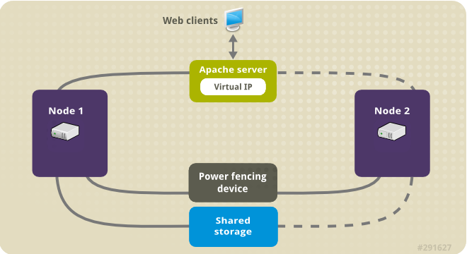
Figure 2.1. Apache in a Red Hat High Availability Two-Node Cluster
This use case requires that your system include the following components:
- A two-node Red Hat High Availability cluster with power fencing configured for each node. This procedure uses the cluster example provided in Chapter 1, Creating a Red Hat High-Availability Cluster with Pacemaker.
- A public virtual IP address, required for Apache.
- Shared storage for the nodes in the cluster, using iSCSI, Fibre Channel, or other shared network block device.
The cluster is configured with an Apache resource group, which contains the cluster components that the web server requires: an LVM resource, a file system resource, an IP address resource, and a web server resource. This resource group can fail over from one node of the cluster to the other, allowing either node to run the web server. Before creating the resource group for this cluster, you will perform the following procedures:
- Configure an
ext4file system mounted on the logical volumemy_lv, as described in Section 2.1, “Configuring an LVM Volume with an ext4 File System”. - Configure a web server, as described in Section 2.2, “Web Server Configuration”.
- Ensure that only the cluster is capable of activating the volume group that contains
my_lv, and that the volume group will not be activated outside of the cluster on startup, as described in Section 2.3, “Exclusive Activation of a Volume Group in a Cluster”.
After performing these procedures, you create the resource group and the resources it contains, as described in Section 2.4, “Creating the Resources and Resource Groups with the pcs Command”.
2.1. Configuring an LVM Volume with an ext4 File System
Copy linkLink copied to clipboard!
This use case requires that you create an LVM logical volume on storage that is shared between the nodes of the cluster.
The following procedure creates an LVM logical volume and then creates an
ext4 file system on that volume. In this example, the shared partition /dev/sdb1 is used to store the LVM physical volume from which the LVM logical volume will be created.
Note
LVM volumes and the corresponding partitions and devices used by cluster nodes must be connected to the cluster nodes only.
Since the
/dev/sdb1 partition is storage that is shared, you perform this procedure on one node only,
- Create an LVM physical volume on partition
/dev/sdb1.pvcreate /dev/sdb1 Physical volume "/dev/sdb1" successfully created
# pvcreate /dev/sdb1
  Physical volume "/dev/sdb1" successfully created
Copy to Clipboard Copied! Toggle word wrap Toggle overflow - Create the volume group
my_vgthat consists of the physical volume/dev/sdb1.vgcreate my_vg /dev/sdb1 Volume group "my_vg" successfully created
# vgcreate my_vg /dev/sdb1
  Volume group "my_vg" successfully created
Copy to Clipboard Copied! Toggle word wrap Toggle overflow - Create a logical volume using the volume group
my_vg.lvcreate -L450 -n my_lv my_vg Rounding up size to full physical extent 452.00 MiB Logical volume "my_lv" created
# lvcreate -L450 -n my_lv my_vg
  Rounding up size to full physical extent 452.00 MiB
  Logical volume "my_lv" created
Copy to Clipboard Copied! Toggle word wrap Toggle overflow You can use thelvscommand to display the logical volume.lvs LV VG Attr LSize Pool Origin Data% Move Log Copy% Convert my_lv my_vg -wi-a---- 452.00m ...
# lvs
  LV      VG      Attr      LSize   Pool Origin Data%  Move Log Copy%  Convert
  my_lv   my_vg   -wi-a---- 452.00m
  ...
Copy to Clipboard Copied! Toggle word wrap Toggle overflow - Create an
ext4file system on the logical volumemy_lv.Copy to Clipboard Copied! Toggle word wrap Toggle overflow
2.2. Web Server Configuration
Copy linkLink copied to clipboard!
The following procedure configures an Apache HTTP server.
- Ensure that the Apache HTTP server is installed on each node in the cluster. You also need the
wgettool installed on the cluster to be able to check the status of the Apache HTTP server.On each node, execute the following command.yum install -y httpd wget
# yum install -y httpd wgetCopy to Clipboard Copied! Toggle word wrap Toggle overflow - In order for the Apache resource agent to get the status of the Apache HTTP server, ensure that the following text is present in the
/etc/httpd/conf/httpd.conffile on each node in the cluster, and ensure that it has not been commented out. If this text is not already present, add the text to the end of the file.<Location /server-status> SetHandler server-status Require local </Location><Location /server-status> SetHandler server-status Require local </Location>Copy to Clipboard Copied! Toggle word wrap Toggle overflow - When you use the
apacheresource agent to manage Apache, it does not usesystemd. Because of this, you must edit thelogrotatescript supplied with Apache so that it does not usesystemctlto reload Apache.Remove the following line in the/etc/logrotate.d/httpdfile on each node in the cluster./bin/systemctl reload httpd.service > /dev/null 2>/dev/null || true
/bin/systemctl reload httpd.service > /dev/null 2>/dev/null || trueCopy to Clipboard Copied! Toggle word wrap Toggle overflow Replace the line you removed with the following three lines./usr/bin/test -f /run/httpd.pid >/dev/null 2>/dev/null && /usr/bin/ps -q $(/usr/bin/cat /run/httpd.pid) >/dev/null 2>/dev/null && /usr/sbin/httpd -f /etc/httpd/conf/httpd.conf -c "PidFile /run/httpd.pid" -k graceful > /dev/null 2>/dev/null || true
/usr/bin/test -f /run/httpd.pid >/dev/null 2>/dev/null && /usr/bin/ps -q $(/usr/bin/cat /run/httpd.pid) >/dev/null 2>/dev/null && /usr/sbin/httpd -f /etc/httpd/conf/httpd.conf -c "PidFile /run/httpd.pid" -k graceful > /dev/null 2>/dev/null || trueCopy to Clipboard Copied! Toggle word wrap Toggle overflow - Create a web page for Apache to serve up. On one node in the cluster, mount the file system you created in Section 2.1, “Configuring an LVM Volume with an ext4 File System”, create the file
index.htmlon that file system, then unmount the file system.Copy to Clipboard Copied! Toggle word wrap Toggle overflow
2.3. Exclusive Activation of a Volume Group in a Cluster
Copy linkLink copied to clipboard!
The following procedure configures the volume group in a way that will ensure that only the cluster is capable of activating the volume group, and that the volume group will not be activated outside of the cluster on startup. If the volume group is activated by a system outside of the cluster, there is a risk of corrupting the volume group's metadata.
This procedure modifies the
volume_list entry in the /etc/lvm/lvm.conf configuration file. Volume groups listed in the volume_list entry are allowed to automatically activate on the local node outside of the cluster manager's control. Volume groups related to the node's local root and home directories should be included in this list. All volume groups managed by the cluster manager must be excluded from the volume_list entry. Note that this procedure does not require the use of clvmd.
Perform the following procedure on each node in the cluster.
- Execute the following command to ensure that
locking_typeis set to 1 and thatuse_lvmetadis set to 0 in the/etc/lvm/lvm.conffile. This command also disables and stops anylvmetadprocesses immediately.lvmconf --enable-halvm --services --startstopservices
# lvmconf --enable-halvm --services --startstopservicesCopy to Clipboard Copied! Toggle word wrap Toggle overflow - Determine which volume groups are currently configured on your local storage with the following command. This will output a list of the currently-configured volume groups. If you have space allocated in separate volume groups for root and for your home directory on this node, you will see those volumes in the output, as in this example.
vgs --noheadings -o vg_name
  my_vg
  rhel_home
  rhel_root
# vgs --noheadings -o vg_name
  my_vg
  rhel_home
  rhel_root
Copy to Clipboard Copied! Toggle word wrap Toggle overflow - Add the volume groups other than
my_vg(the volume group you have just defined for the cluster) as entries tovolume_listin the/etc/lvm/lvm.confconfiguration file.For example, if you have space allocated in separate volume groups for root and for your home directory, you would uncomment thevolume_listline of thelvm.conffile and add these volume groups as entries tovolume_listas follows. Note that the volume group you have just defined for the cluster (my_vgin this example) is not in this list.volume_list = [ "rhel_root", "rhel_home" ]
volume_list = [ "rhel_root", "rhel_home" ]Copy to Clipboard Copied! Toggle word wrap Toggle overflow Note
If no local volume groups are present on a node to be activated outside of the cluster manager, you must still initialize thevolume_listentry asvolume_list = []. - Rebuild the
initramfsboot image to guarantee that the boot image will not try to activate a volume group controlled by the cluster. Update theinitramfsdevice with the following command. This command may take up to a minute to complete.dracut -H -f /boot/initramfs-$(uname -r).img $(uname -r)
# dracut -H -f /boot/initramfs-$(uname -r).img $(uname -r)Copy to Clipboard Copied! Toggle word wrap Toggle overflow - Reboot the node.
Note
If you have installed a new Linux kernel since booting the node on which you created the boot image, the newinitrdimage will be for the kernel that was running when you created it and not for the new kernel that is running when you reboot the node. You can ensure that the correctinitrddevice is in use by running theuname -rcommand before and after the reboot to determine the kernel release that is running. If the releases are not the same, update theinitrdfile after rebooting with the new kernel and then reboot the node. - When the node has rebooted, check whether the cluster services have started up again on that node by executing the
pcs cluster statuscommand on that node. If this yields the messageError: cluster is not currently running on this nodethen enter the following command.pcs cluster start
# pcs cluster startCopy to Clipboard Copied! Toggle word wrap Toggle overflow Alternately, you can wait until you have rebooted each node in the cluster and start cluster services on each of the nodes with the following command.pcs cluster start --all
# pcs cluster start --allCopy to Clipboard Copied! Toggle word wrap Toggle overflow
2.4. Creating the Resources and Resource Groups with the pcs Command
Copy linkLink copied to clipboard!
This use case requires that you create four cluster resources. To ensure these resources all run on the same node, they are configured as part of the resource group
apachegroup. The resources to create are as follows, listed in the order in which they will start.
- An
LVMresource namedmy_lvmthat uses the LVM volume group you created in Section 2.1, “Configuring an LVM Volume with an ext4 File System”. - A
Filesystemresource namedmy_fs, that uses the file system device/dev/my_vg/my_lvyou created in Section 2.1, “Configuring an LVM Volume with an ext4 File System”. - An
IPaddr2resource, which is a floating IP address for theapachegroupresource group. The IP address must not be one already associated with a physical node. If theIPaddr2resource's NIC device is not specified, the floating IP must reside on the same network as the statically assigned IP addresses used by the cluster nodes, otherwise the NIC device to assign the floating IP address cannot be properly detected. - An
apacheresource namedWebsitethat uses theindex.htmlfile and the Apache configuration you defined in Section 2.2, “Web Server Configuration”.
The following procedure creates the resource group
apachegroup and the resources that the group contains. The resources will start in the order in which you add them to the group, and they will stop in the reverse order in which they are added to the group. Run this procedure from one node of the cluster only.
- The following command creates the LVM resource
my_lvm. This command specifies theexclusive=trueparameter to ensure that only the cluster is capable of activating the LVM logical volume. Because the resource groupapachegroupdoes not yet exist, this command creates the resource group.pcs resource create my_lvm LVM volgrpname=my_vg \ exclusive=true --group apachegroup
[root@z1 ~]# pcs resource create my_lvm LVM volgrpname=my_vg \
exclusive=true --group apachegroup
Copy to Clipboard Copied! Toggle word wrap Toggle overflow When you create a resource, the resource is started automatically. You can use the following command to confirm that the resource was created and has started.pcs resource show Resource Group: apachegroup my_lvm (ocf::heartbeat:LVM): Started# pcs resource show Resource Group: apachegroup my_lvm (ocf::heartbeat:LVM): StartedCopy to Clipboard Copied! Toggle word wrap Toggle overflow You can manually stop and start an individual resource with thepcs resource disableandpcs resource enablecommands. - The following commands create the remaining resources for the configuration, adding them to the existing resource group
apachegroup.Copy to Clipboard Copied! Toggle word wrap Toggle overflow - After creating the resources and the resource group that contains them, you can check the status of the cluster. Note that all four resources are running on the same node.
Copy to Clipboard Copied! Toggle word wrap Toggle overflow Note that if you have not configured a fencing device for your cluster, as described in Section 1.3, “Fencing Configuration”, by default the resources do not start. - Once the cluster is up and running, you can point a browser to the IP address you defined as the
IPaddr2resource to view the sample display, consisting of the simple word "Hello".Hello
HelloCopy to Clipboard Copied! Toggle word wrap Toggle overflow If you find that the resources you configured are not running, you can run thepcs resource debug-start resourcecommand to test the resource configuration. For information on thepcs resource debug-startcommand, see the High Availability Add-On Reference manual.
2.5. Testing the Resource Configuration
Copy linkLink copied to clipboard!
In the cluster status display shown in Section 2.4, “Creating the Resources and Resource Groups with the pcs Command”, all of the resources are running on node
z1.example.com. You can test whether the resource group fails over to node z2.example.com by using the following procedure to put the first node in standby mode, after which the node will no longer be able to host resources.
- The following command puts node
z1.example.cominstandbymode.root@z1 ~]# pcs node standby z1.example.com
root@z1 ~]# pcs node standby z1.example.comCopy to Clipboard Copied! Toggle word wrap Toggle overflow - After putting node
z1in standby mode, check the cluster status. Note that the resources should now all be running onz2.Copy to Clipboard Copied! Toggle word wrap Toggle overflow The web site at the defined IP address should still display, without interruption. - To remove
z1fromstandbymode, enter the following command.root@z1 ~]# pcs node unstandby z1.example.com
root@z1 ~]# pcs node unstandby z1.example.comCopy to Clipboard Copied! Toggle word wrap Toggle overflow Note
Removing a node fromstandbymode does not in itself cause the resources to fail back over to that node. This will depend on theresource-stickinessvalue for the resources. For information on theresource-stickinessmeta attribute, see Configuring a Resource to Prefer its Current Node in the Red Hat High Availability Add-On Reference.
Chapter 3. An active/passive NFS Server in a Red Hat High Availability Cluster
Copy linkLink copied to clipboard!
This chapter describes how to configure a highly available active/passive NFS server on a two-node Red Hat Enterprise Linux High Availability Add-On cluster using shared storage. The procedure uses
pcs to configure Pacemaker cluster resources. In this use case, clients access the NFS file system through a floating IP address. The NFS server runs on one of two nodes in the cluster. If the node on which the NFS server is running becomes inoperative, the NFS server starts up again on the second node of the cluster with minimal service interruption.
This use case requires that your system include the following components:
- Two nodes, which will be used to create the cluster running the Apache HTTP server. In this example, the nodes used are
z1.example.comandz2.example.com. - A power fencing device for each node of the cluster. This example uses two ports of the APC power switch with a host name of
zapc.example.com. - A public virtual IP address, required for the NFS server.
- Shared storage for the nodes in the cluster, using iSCSI, Fibre Channel, or other shared network block device.
Configuring a highly available active/passive NFS server on a two-node Red Hat Enterprise Linux High requires that you perform the following steps.
- Create the cluster that will run the NFS server and configure fencing for each node in the cluster, as described in Section 3.1, “Creating the NFS Cluster”.
- Configure an
ext4file system mounted on the LVM logical volumemy_lvon the shared storage for the nodes in the cluster, as described in Section 3.2, “Configuring an LVM Volume with an ext4 File System”. - Configure an NFS share on the shared storage on the LVM logical volume, as described in Section 3.3, “NFS Share Setup”.
- Ensure that only the cluster is capable of activating the LVM volume group that contains the logical volume
my_lv, and that the volume group will not be activated outside of the cluster on startup, as described in Section 3.4, “Exclusive Activation of a Volume Group in a Cluster”. - Create the cluster resources as described in Section 3.5, “Configuring the Cluster Resources”.
- Test the NFS server you have configured, as described in Section 3.6, “Testing the Resource Configuration”.
3.1. Creating the NFS Cluster
Copy linkLink copied to clipboard!
Use the following procedure to install and create the NFS cluster.
- Install the cluster software on nodes
z1.example.comandz2.example.com, using the procedure provided in Section 1.1, “Cluster Software Installation”. - Create the two-node cluster that consists of
z1.example.comandz2.example.com, using the procedure provided in Section 1.2, “Cluster Creation”. As in that example procedure, this use case names the clustermy_cluster. - Configure fencing devices for each node of the cluster, using the procedure provided in Section 1.3, “Fencing Configuration”. This example configures fencing using two ports of the APC power switch with a host name of
zapc.example.com.
3.2. Configuring an LVM Volume with an ext4 File System
Copy linkLink copied to clipboard!
This use case requires that you create an LVM logical volume on storage that is shared between the nodes of the cluster.
The following procedure creates an LVM logical volume and then creates an
ext4 file system on that volume. In this example, the shared partition /dev/sdb1 is used to store the LVM physical volume from which the LVM logical volume will be created.
Note
LVM volumes and the corresponding partitions and devices used by cluster nodes must be connected to the cluster nodes only.
Since the
/dev/sdb1 partition is storage that is shared, you perform this procedure on one node only,
- Create an LVM physical volume on partition
/dev/sdb1.pvcreate /dev/sdb1 Physical volume "/dev/sdb1" successfully created
[root@z1 ~]# pvcreate /dev/sdb1
  Physical volume "/dev/sdb1" successfully created
Copy to Clipboard Copied! Toggle word wrap Toggle overflow - Create the volume group
my_vgthat consists of the physical volume/dev/sdb1.vgcreate my_vg /dev/sdb1 Volume group "my_vg" successfully created
[root@z1 ~]# vgcreate my_vg /dev/sdb1
  Volume group "my_vg" successfully created
Copy to Clipboard Copied! Toggle word wrap Toggle overflow - Create a logical volume using the volume group
my_vg.lvcreate -L450 -n my_lv my_vg Rounding up size to full physical extent 452.00 MiB Logical volume "my_lv" created
[root@z1 ~]# lvcreate -L450 -n my_lv my_vg
  Rounding up size to full physical extent 452.00 MiB
  Logical volume "my_lv" created
Copy to Clipboard Copied! Toggle word wrap Toggle overflow You can use thelvscommand to display the logical volume.lvs LV VG Attr LSize Pool Origin Data% Move Log Copy% Convert my_lv my_vg -wi-a---- 452.00m ...
[root@z1 ~]# lvs
  LV      VG      Attr      LSize   Pool Origin Data%  Move Log Copy%  Convert
  my_lv   my_vg   -wi-a---- 452.00m
  ...
Copy to Clipboard Copied! Toggle word wrap Toggle overflow - Create an
ext4file system on the logical volumemy_lv.Copy to Clipboard Copied! Toggle word wrap Toggle overflow
3.4. Exclusive Activation of a Volume Group in a Cluster
Copy linkLink copied to clipboard!
The following procedure configures the LVM volume group in a way that will ensure that only the cluster is capable of activating the volume group, and that the volume group will not be activated outside of the cluster on startup. If the volume group is activated by a system outside of the cluster, there is a risk of corrupting the volume group's metadata.
This procedure modifies the
volume_list entry in the /etc/lvm/lvm.conf configuration file. Volume groups listed in the volume_list entry are allowed to automatically activate on the local node outside of the cluster manager's control. Volume groups related to the node's local root and home directories should be included in this list. All volume groups managed by the cluster manager must be excluded from the volume_list entry. Note that this procedure does not require the use of clvmd.
Perform the following procedure on each node in the cluster.
- Execute the following command to ensure that
locking_typeis set to 1 and thatuse_lvmetadis set to 0 in the/etc/lvm/lvm.conffile. This command also disables and stops anylvmetadprocesses immediately.lvmconf --enable-halvm --services --startstopservices
# lvmconf --enable-halvm --services --startstopservicesCopy to Clipboard Copied! Toggle word wrap Toggle overflow - Determine which volume groups are currently configured on your local storage with the following command. This will output a list of the currently-configured volume groups. If you have space allocated in separate volume groups for root and for your home directory on this node, you will see those volumes in the output, as in this example.
vgs --noheadings -o vg_name
  my_vg
  rhel_home
  rhel_root
# vgs --noheadings -o vg_name
  my_vg
  rhel_home
  rhel_root
Copy to Clipboard Copied! Toggle word wrap Toggle overflow - Add the volume groups other than
my_vg(the volume group you have just defined for the cluster) as entries tovolume_listin the/etc/lvm/lvm.confconfiguration file. For example, if you have space allocated in separate volume groups for root and for your home directory, you would uncomment thevolume_listline of thelvm.conffile and add these volume groups as entries tovolume_listas follows:volume_list = [ "rhel_root", "rhel_home" ]
volume_list = [ "rhel_root", "rhel_home" ]Copy to Clipboard Copied! Toggle word wrap Toggle overflow Note
If no local volume groups are present on a node to be activated outside of the cluster manager, you must still initialize thevolume_listentry asvolume_list = []. - Rebuild the
initramfsboot image to guarantee that the boot image will not try to activate a volume group controlled by the cluster. Update theinitramfsdevice with the following command. This command may take up to a minute to complete.dracut -H -f /boot/initramfs-$(uname -r).img $(uname -r)
# dracut -H -f /boot/initramfs-$(uname -r).img $(uname -r)Copy to Clipboard Copied! Toggle word wrap Toggle overflow - Reboot the node.
Note
If you have installed a new Linux kernel since booting the node on which you created the boot image, the newinitrdimage will be for the kernel that was running when you created it and not for the new kernel that is running when you reboot the node. You can ensure that the correctinitrddevice is in use by running theuname -rcommand before and after the reboot to determine the kernel release that is running. If the releases are not the same, update theinitrdfile after rebooting with the new kernel and then reboot the node. - When the node has rebooted, check whether the cluster services have started up again on that node by executing the
pcs cluster statuscommand on that node. If this yields the messageError: cluster is not currently running on this nodethen enter the following command.pcs cluster start
# pcs cluster startCopy to Clipboard Copied! Toggle word wrap Toggle overflow Alternately, you can wait until you have rebooted each node in the cluster and start cluster services on all of the nodes in the cluster with the following command.pcs cluster start --all
# pcs cluster start --allCopy to Clipboard Copied! Toggle word wrap Toggle overflow
3.5. Configuring the Cluster Resources
Copy linkLink copied to clipboard!
This section provides the procedure for configuring the cluster resources for this use case.
Note
It is recommended that when you create a cluster resource with the
pcs resource create, you execute the pcs status command immediately afterwards to verify that the resource is running. Note that if you have not configured a fencing device for your cluster, as described in Section 1.3, “Fencing Configuration”, by default the resources do not start.
If you find that the resources you configured are not running, you can run the
pcs resource debug-start resource command to test the resource configuration. This starts the service outside of the cluster’s control and knowledge. At the point the configured resources are running again, run pcs resource cleanup resource to make the cluster aware of the updates. For information on the pcs resource debug-start command, see the High Availability Add-On Reference manual.
The following procedure configures the system resources. To ensure these resources all run on the same node, they are configured as part of the resource group
nfsgroup. The resources will start in the order in which you add them to the group, and they will stop in the reverse order in which they are added to the group. Run this procedure from one node of the cluster only.
- The following command creates the LVM resource named
my_lvm. This command specifies theexclusive=trueparameter to ensure that only the cluster is capable of activating the LVM logical volume. Because the resource groupnfsgroupdoes not yet exist, this command creates the resource group.pcs resource create my_lvm LVM volgrpname=my_vg \ exclusive=true --group nfsgroup
[root@z1 ~]# pcs resource create my_lvm LVM volgrpname=my_vg \
exclusive=true --group nfsgroup
Copy to Clipboard Copied! Toggle word wrap Toggle overflow Check the status of the cluster to verify that the resource is running.Copy to Clipboard Copied! Toggle word wrap Toggle overflow - Configure a
Filesystemresource for the cluster.Note
You can specify mount options as part of the resource configuration for aFilesystemresource with theoptions=optionsparameter. Run thepcs resource describe Filesystemcommand for full configuration options.The following command configures an ext4Filesystemresource namednfsshareas part of thenfsgroupresource group. This file system uses the LVM volume group and ext4 file system you created in Section 3.2, “Configuring an LVM Volume with an ext4 File System” and will be mounted on the/nfssharedirectory you created in Section 3.3, “NFS Share Setup”.pcs resource create nfsshare Filesystem \ device=/dev/my_vg/my_lv directory=/nfsshare \ fstype=ext4 --group nfsgroup
[root@z1 ~]# pcs resource create nfsshare Filesystem \
device=/dev/my_vg/my_lv directory=/nfsshare \
fstype=ext4 --group nfsgroup
Copy to Clipboard Copied! Toggle word wrap Toggle overflow Verify that themy_lvmandnfsshareresources are running.Copy to Clipboard Copied! Toggle word wrap Toggle overflow - Create the
nfsserverresource namednfs-daemonpart of the resource groupnfsgroup.Note
Thenfsserverresource allows you to specify annfs_shared_infodirparameter, which is a directory that NFS daemons will use to store NFS-related stateful information. It is recommended that this attribute be set to a subdirectory of one of theFilesystemresources you created in this collection of exports. This ensures that the NFS daemons are storing their stateful information on a device that will become available to another node if this resource group should need to relocate. In this example,/nfsshareis the shared-storage directory managed by theFilesystemresource,/nfsshare/exports/export1and/nfsshare/exports/export2are the export directories, and/nfsshare/nfsinfois the shared-information directory for thenfsserverresource.Copy to Clipboard Copied! Toggle word wrap Toggle overflow - Add the
exportfsresources to export the/nfsshare/exportsdirectory. These resources are part of the resource groupnfsgroup. This builds a virtual directory for NFSv4 clients. NFSv3 clients can access these exports as well.Copy to Clipboard Copied! Toggle word wrap Toggle overflow - Add the floating IP address resource that NFS clients will use to access the NFS share. The floating IP address that you specify requires a reverse DNS lookup or it must be specified in the
/etc/hostson all nodes in the cluster. This resource is part of the resource groupnfsgroup. For this example deployment, we are using 192.168.122.200 as the floating IP address.pcs resource create nfs_ip IPaddr2 \ ip=192.168.122.200 cidr_netmask=24 --group nfsgroup
[root@z1 ~]# pcs resource create nfs_ip IPaddr2 \
ip=192.168.122.200 cidr_netmask=24 --group nfsgroup
Copy to Clipboard Copied! Toggle word wrap Toggle overflow - Add an
nfsnotifyresource for sending NFSv3 reboot notifications once the entire NFS deployment has initialized. This resource is part of the resource groupnfsgroup.Note
For the NFS notification to be processed correctly, the floating IP address must have a host name associated with it that is consistent on both the NFS servers and the NFS client.pcs resource create nfs-notify nfsnotify \ source_host=192.168.122.200 --group nfsgroup
[root@z1 ~]# pcs resource create nfs-notify nfsnotify \
source_host=192.168.122.200 --group nfsgroup
Copy to Clipboard Copied! Toggle word wrap Toggle overflow
After creating the resources and the resource constraints, you can check the status of the cluster. Note that all resources are running on the same node.
3.6. Testing the Resource Configuration
Copy linkLink copied to clipboard!
You can validate your system configuration with the following procedure. You should be able to mount the exported file system with either NFSv3 or NFSv4.
- On a node outside of the cluster, residing in the same network as the deployment, verify that the NFS share can be seen by mounting the NFS share. For this example, we are using the 192.168.122.0/24 network.
Copy to Clipboard Copied! Toggle word wrap Toggle overflow - To verify that you can mount the NFS share with NFSv4, mount the NFS share to a directory on the client node. After mounting, verify that the contents of the export directories are visible. Unmount the share after testing.
mkdir nfsshare
mount -o "vers=4" 192.168.122.200:export1 nfsshare
ls nfsshare
clientdatafile1
umount nfsshare
# mkdir nfsshare
# mount -o "vers=4" 192.168.122.200:export1 nfsshare
# ls nfsshare
clientdatafile1
# umount nfsshare
Copy to Clipboard Copied! Toggle word wrap Toggle overflow - Verify that you can mount the NFS share with NFSv3. After mounting, verify that the test file
clientdatafile1is visible. Unlike NFSv4, since NFSV3 does not use the virtual file system, you must mount a specific export. Unmount the share after testing.mkdir nfsshare mount -o "vers=3" 192.168.122.200:/nfsshare/exports/export2 nfsshare ls nfsshare clientdatafile2 umount nfsshare# mkdir nfsshare # mount -o "vers=3" 192.168.122.200:/nfsshare/exports/export2 nfsshare # ls nfsshare clientdatafile2 # umount nfsshareCopy to Clipboard Copied! Toggle word wrap Toggle overflow - To test for failover, perform the following steps.
- On a node outside of the cluster, mount the NFS share and verify access to the
clientdatafile1we created in Section 3.3, “NFS Share Setup”.mkdir nfsshare mount -o "vers=4" 192.168.122.200:export1 nfsshare ls nfsshare clientdatafile1
# mkdir nfsshare
# mount -o "vers=4" 192.168.122.200:export1 nfsshare
# ls nfsshare
clientdatafile1
Copy to Clipboard Copied! Toggle word wrap Toggle overflow - From a node within the cluster, determine which node in the cluster is running
nfsgroup. In this example,nfsgroupis running onz1.example.com.Copy to Clipboard Copied! Toggle word wrap Toggle overflow - From a node within the cluster, put the node that is running
nfsgroupin standby mode.pcs node standby z1.example.com
[root@z1 ~]# pcs node standby z1.example.comCopy to Clipboard Copied! Toggle word wrap Toggle overflow - Verify that
nfsgroupsuccessfully starts on the other cluster node.Copy to Clipboard Copied! Toggle word wrap Toggle overflow - From the node outside the cluster on which you have mounted the NFS share, verify that this outside node still continues to have access to the test file within the NFS mount.
ls nfsshare
clientdatafile1
# ls nfsshare
clientdatafile1
Copy to Clipboard Copied! Toggle word wrap Toggle overflow Service will be lost briefly for the client during the failover briefly but the client should recover in with no user intervention. By default, clients using NFSv4 may take up to 90 seconds to recover the mount; this 90 seconds represents the NFSv4 file lease grace period observed by the server on startup. NFSv3 clients should recover access to the mount in a matter of a few seconds. - From a node within the cluster, remove the node that was initially running running
nfsgroupfrom standby mode. This will not in itself move the cluster resources back to this node.pcs node unstandby z1.example.com
[root@z1 ~]# pcs node unstandby z1.example.comCopy to Clipboard Copied! Toggle word wrap Toggle overflow Note
Removing a node fromstandbymode does not in itself cause the resources to fail back over to that node. This will depend on theresource-stickinessvalue for the resources. For information on theresource-stickinessmeta attribute, see Configuring a Resource to Prefer its Current Node in the Red Hat High Availability Add-On Reference.
Chapter 4. An active/active Samba Server in a Red Hat High Availability Cluster (Red Hat Enterprise Linux 7.4 and Later)
Copy linkLink copied to clipboard!
As of the Red Hat Enterprise Linux 7.4 release, the Red Hat Resilient Storage Add-On provides support for running Samba in an active/active cluster configuration using Pacemaker. The Red Hat Resilient Storage Add-On includes the High Availability Add-On.
Note
For further information on support policies for Samba, see Support Policies for RHEL Resilient Storage - ctdb General Policies and Support Policies for RHEL Resilient Storage - Exporting gfs2 contents via other protocols on the Red Hat Customer Portal.
This chapter describes how to configure a highly available active/active Samba server on a two-node Red Hat Enterprise Linux High Availability Add-On cluster using shared storage. The procedure uses
pcs to configure Pacemaker cluster resources.
This use case requires that your system include the following components:
- Two nodes, which will be used to create the cluster running Clustered Samba. In this example, the nodes used are
z1.example.comandz2.example.comwhich have IP address of192.168.1.151and192.168.1.152. - A power fencing device for each node of the cluster. This example uses two ports of the APC power switch with a host name of
zapc.example.com. - Shared storage for the nodes in the cluster, using iSCSI or Fibre Channel.
Configuring a highly available active/active Samba server on a two-node Red Hat Enterprise Linux High Availability Add-On cluster requires that you perform the following steps.
- Create the cluster that will export the Samba shares and configure fencing for each node in the cluster, as described in Section 4.1, “Creating the Cluster”.
- Configure a
gfs2file system mounted on the clustered LVM logical volumemy_clvon the shared storage for the nodes in the cluster, as described in Section 4.2, “Configuring a Clustered LVM Volume with a GFS2 File System”. - Configure Samba on each node in the cluster, Section 4.3, “Configuring Samba”.
- Create the Samba cluster resources as described in Section 4.4, “Configuring the Samba Cluster Resources”.
- Test the Samba share you have configured, as described in Section 4.5, “Testing the Resource Configuration”.
4.1. Creating the Cluster
Copy linkLink copied to clipboard!
Use the following procedure to install and create the cluster to use for the Samba service:
- Install the cluster software on nodes
z1.example.comandz2.example.com, using the procedure provided in Section 1.1, “Cluster Software Installation”. - Create the two-node cluster that consists of
z1.example.comandz2.example.com, using the procedure provided in Section 1.2, “Cluster Creation”. As in that example procedure, this use case names the clustermy_cluster. - Configure fencing devices for each node of the cluster, using the procedure provided in Section 1.3, “Fencing Configuration”. This example configures fencing using two ports of the APC power switch with a host name of
zapc.example.com.
4.2. Configuring a Clustered LVM Volume with a GFS2 File System
Copy linkLink copied to clipboard!
This use case requires that you create a clustered LVM logical volume on storage that is shared between the nodes of the cluster.
This section describes how to create a clustered LVM logical volume with a GFS2 file system on that volume. In this example, the shared partition
/dev/vdb is used to store the LVM physical volume from which the LVM logical volume will be created.
Note
LVM volumes and the corresponding partitions and devices used by cluster nodes must be connected to the cluster nodes only.
Before starting this procedure, install the
lvm2-cluster and gfs2-utils packages, which are part of the Resilient Storage channel, on both nodes of the cluster.
yum install lvm2-cluster gfs2-utils
# yum install lvm2-cluster gfs2-utils
Since the
/dev/vdb partition is storage that is shared, you perform this procedure on one node only,
- Set the global Pacemaker parameter
no_quorum_policytofreeze. This prevents the entire cluster from being fenced every time quorum is lost. For further information on setting this policy, see Global File System 2.pcs property set no-quorum-policy=freeze
[root@z1 ~]# pcs property set no-quorum-policy=freezeCopy to Clipboard Copied! Toggle word wrap Toggle overflow - Set up a
dlmresource. This is a required dependency for theclvmdservice and the GFS2 file system.pcs resource create dlm ocf:pacemaker:controld op monitor interval=30s on-fail=fence clone interleave=true ordered=true
[root@z1 ~]# pcs resource create dlm ocf:pacemaker:controld op monitor interval=30s on-fail=fence clone interleave=true ordered=trueCopy to Clipboard Copied! Toggle word wrap Toggle overflow - Set up
clvmdas a cluster resource.pcs resource create clvmd ocf:heartbeat:clvm op monitor interval=30s on-fail=fence clone interleave=true ordered=true
[root@z1 ~]# pcs resource create clvmd ocf:heartbeat:clvm op monitor interval=30s on-fail=fence clone interleave=true ordered=trueCopy to Clipboard Copied! Toggle word wrap Toggle overflow Note that theocf:heartbeat:clvmresource agent, as part of the start procedure, sets thelocking_typeparameter in the/etc/lvm/lvm.conffile to3and disables thelvmetaddaemon. - Set up
clvmdanddlmdependency and start up order. Theclvmdresource must start after thedlmresource and must run on the same node as thedlmresource.pcs constraint order start dlm-clone then clvmd-clone Adding dlm-clone clvmd-clone (kind: Mandatory) (Options: first-action=start then-action=start) pcs constraint colocation add clvmd-clone with dlm-clone
[root@z1 ~]# pcs constraint order start dlm-clone then clvmd-clone
Adding dlm-clone clvmd-clone (kind: Mandatory) (Options: first-action=start then-action=start)
[root@z1 ~]# pcs constraint colocation add clvmd-clone with dlm-clone
Copy to Clipboard Copied! Toggle word wrap Toggle overflow - Verify that the
dlmandclvmdresources are running on all nodes.Copy to Clipboard Copied! Toggle word wrap Toggle overflow - Create the clustered logical volume
pvcreate /dev/vdb
vgcreate -Ay -cy cluster_vg /dev/vdb
lvcreate -L4G -n cluster_lv cluster_vg
[root@z1 ~]# pvcreate /dev/vdb
[root@z1 ~]# vgcreate -Ay -cy cluster_vg /dev/vdb
[root@z1 ~]# lvcreate -L4G -n cluster_lv cluster_vg
Copy to Clipboard Copied! Toggle word wrap Toggle overflow - Optionally, to verify that the volume was created successfully you can use the
lvscommand to display the logical volume.lvs LV VG Attr LSize ... cluster_lv cluster_vg -wi-ao---- 4.00g ...
[root@z1 ~]# lvs
  LV         VG         Attr       LSize ...
  cluster_lv cluster_vg -wi-ao---- 4.00g
  ...
Copy to Clipboard Copied! Toggle word wrap Toggle overflow - Format the volume with a GFS2 file system. In this example,
my_clusteris the cluster name. This example specifies-j 2to indicate two journals because the number of journals you configure must equal the number of nodes in the cluster.mkfs.gfs2 -p lock_dlm -j 2 -t my_cluster:samba /dev/cluster_vg/cluster_lv
[root@z1 ~]# mkfs.gfs2 -p lock_dlm -j 2 -t my_cluster:samba /dev/cluster_vg/cluster_lvCopy to Clipboard Copied! Toggle word wrap Toggle overflow - Create a
Filesystemresource, which configures Pacemaker to mount and manage the file system. This example creates aFilesystemresource namedfs, and creates the/mnt/gfs2shareon both nodes of the cluster.pcs resource create fs ocf:heartbeat:Filesystem device="/dev/cluster_vg/cluster_lv" directory="/mnt/gfs2share" fstype="gfs2" --clone
[root@z1 ~]# pcs resource create fs ocf:heartbeat:Filesystem device="/dev/cluster_vg/cluster_lv" directory="/mnt/gfs2share" fstype="gfs2" --cloneCopy to Clipboard Copied! Toggle word wrap Toggle overflow - Configure a dependency and a startup order for the GFS2 file system and the
clvmdservice. GFS2 must start afterclvmdand must run on the same node asclvmd.pcs constraint order start clvmd-clone then fs-clone Adding clvmd-clone fs-clone (kind: Mandatory) (Options: first-action=start then-action=start) pcs constraint colocation add fs-clone with clvmd-clone
[root@z1 ~]# pcs constraint order start clvmd-clone then fs-clone
Adding clvmd-clone fs-clone (kind: Mandatory) (Options: first-action=start then-action=start)
[root@z1 ~]# pcs constraint colocation add fs-clone with clvmd-clone
Copy to Clipboard Copied! Toggle word wrap Toggle overflow - Verify that the GFS2 file system is mounted as expected.
mount |grep /mnt/gfs2share
/dev/mapper/cluster_vg-cluster_lv on /mnt/gfs2share type gfs2 (rw,noatime,seclabel)
[root@z1 ~]# mount |grep /mnt/gfs2share
/dev/mapper/cluster_vg-cluster_lv on /mnt/gfs2share type gfs2 (rw,noatime,seclabel)
Copy to Clipboard Copied! Toggle word wrap Toggle overflow
4.3. Configuring Samba
Copy linkLink copied to clipboard!
The following procedure initializes the Samba environment and configures Samba on the cluster nodes.
- On both nodes of the cluster, perform the following steps:
- Install the
samba,ctdb, andcifs-utilspackages.yum install samba ctdb cifs-utils
# yum install samba ctdb cifs-utilsCopy to Clipboard Copied! Toggle word wrap Toggle overflow - If you are running the
firewallddaemon, run the following commands to enable the ports that are required by thectdbandsambaservices.firewall-cmd --add-service=ctdb --permanent firewall-cmd --add-service=samba --permanent firewall-cmd --reload
# firewall-cmd --add-service=ctdb --permanent
# firewall-cmd --add-service=samba --permanent
# firewall-cmd --reload
Copy to Clipboard Copied! Toggle word wrap Toggle overflow - Enter the following commands to ensure that these daemons are not running and do not start at bootup. Note that not all of these daemons may be present or running on your system.
Copy to Clipboard Copied! Toggle word wrap Toggle overflow - In the
/etc/samba/smb.conffile, configure the Samba server and set up the[public]share definition. For example:Copy to Clipboard Copied! Toggle word wrap Toggle overflow For information on configuring Samba as a standalone server, as in this example, as well as information on verifying thesmb.conffile with thetestparmutility, see the File and Print Servers section of the System Administrator's Guide - Add the IP address of the cluster nodes to the
/etc/ctdb/nodesfile.cat << END > /etc/ctdb/nodes 192.168.1.151 192.168.1.152 END
# cat << END > /etc/ctdb/nodes
192.168.1.151
192.168.1.152
END
Copy to Clipboard Copied! Toggle word wrap Toggle overflow - For load balancing between the nodes of the cluster, you can add two or more IP addresses that can be used to access the Samba shares exported by this cluster to the
/etc/ctdb/public_addressesfile. These are the IP addresses that you should configure in DNS for the name of the Samba server and are the addresses that SMB clients will connect to. Configure the name of the Samba server as one DNS type A record with multiple IP addresses and let round-robin DNS distribute the clients across the nodes of the cluster.For this example, the DNS entrylinuxserver.example.comhas been defined with both the addresses listed under the/etc/ctdb/public_addressesfile. With this in place, DNS will distribute the Samba clients across the cluster nodes in a round-robin fashion. Please note that when implementing this scenario, the DNS entries should match your needs.Add the IP addresses that can be used to access the Samba shares exported by this cluster to the/etc/ctdb/public_addressesfile.cat << END > /etc/ctdb/public_addresses 192.168.1.201/24 eth0 192.168.1.202/24 eth0 END
# cat << END > /etc/ctdb/public_addresses
192.168.1.201/24 eth0
192.168.1.202/24 eth0
END
Copy to Clipboard Copied! Toggle word wrap Toggle overflow - Create a Samba group, then add a local user for the public test share directory, setting the previously created group as the primary group.
groupadd smbguest
adduser smbguest -g smbguest
# groupadd smbguest
# adduser smbguest -g smbguest
Copy to Clipboard Copied! Toggle word wrap Toggle overflow - Make sure that the SELinux context are correct in the CTDB-related directories.
Copy to Clipboard Copied! Toggle word wrap Toggle overflow
- On one node of the cluster, perform the following steps:
- Set up the directories for the CTDB lock file and public share.
mkdir -p /mnt/gfs2share/ctdb/
mkdir -p /mnt/gfs2share/public/
[root@z1 ~]# mkdir -p /mnt/gfs2share/ctdb/
[root@z1 ~]# mkdir -p /mnt/gfs2share/public/
Copy to Clipboard Copied! Toggle word wrap Toggle overflow - Update the SELinux contexts on the GFS2 share.
Copy to Clipboard Copied! Toggle word wrap Toggle overflow
4.4. Configuring the Samba Cluster Resources
Copy linkLink copied to clipboard!
This section provides the procedure for configuring the Samba cluster resources for this use case.
The following procedure creates a snapshot of the cluster's
cib file named samba.cib and adds the resources to that test file rather then configuring them directly on the running cluster. After the resources and constraints are configured, the procedure pushes the contents of samba.cib to the running cluster configuration file.
On one node of the cluster, run the following procedure.
- Create a snapshot of the
cibfile, which is the cluster configuration file.pcs cluster cib samba.cib
[root@z1 ~]# pcs cluster cib samba.cibCopy to Clipboard Copied! Toggle word wrap Toggle overflow - Create the CTDB resource to be used by Samba. Create this resource as a cloned resource so that it will run on both cluster nodes.
Copy to Clipboard Copied! Toggle word wrap Toggle overflow - Create the cloned Samba server.
pcs -f samba.cib resource create samba systemd:smb --clone
[root@z1 ~]# pcs -f samba.cib resource create samba systemd:smb --cloneCopy to Clipboard Copied! Toggle word wrap Toggle overflow - Create the colocation and order constraints for the cluster resources. The startup order is Filesystem resource, CTDB resource, then Samba resource.
Copy to Clipboard Copied! Toggle word wrap Toggle overflow - Push the content of the
cibsnapshot to the cluster.pcs cluster cib-push samba.cib CIB updated
[root@z1 ~]# pcs cluster cib-push samba.cib
CIB updated
Copy to Clipboard Copied! Toggle word wrap Toggle overflow - Check the status of the cluster to verify that the resource is running.Note that in Red Hat Enterprise Linux 7.4 it can take a couple of minutes for CTDB to start Samba, export the shares, and stabilize. If you check the cluster status before this process has completed, you may see a message that the CTDB status call failed. Once this process has completed, you can clear this message from the display by running the
pcs resource cleanup ctdb-clonecommand.Copy to Clipboard Copied! Toggle word wrap Toggle overflow Note
If you find that the resources you configured are not running, you can run thepcs resource debug-start resourcecommand to test the resource configuration. This starts the service outside of the cluster’s control and knowledge. If the configured resources are running again, runpcs resource cleanup resourceto make the cluster aware of the updates. For information on thepcs resource debug-startcommand, see the Enabling, Disabling, and Banning Cluster Resources section in the High Availability Add-On Reference manual.
4.5. Testing the Resource Configuration
Copy linkLink copied to clipboard!
If the Samba configuration was successful, you should be able to mount the Samba share on a node in the cluster. The following example procedure mounts a Samba share.
- Add an existing user in the cluster node to the
smbpasswdfile and assign a password. In the following example, there is an existing usersmbuser.smbpasswd -a smbuser New SMB password: Retype new SMB password: Added user smbuser
[root@z1 ~]# smbpasswd -a smbuser
New SMB password:
Retype new SMB password:
Added user smbuser
Copy to Clipboard Copied! Toggle word wrap Toggle overflow - Mount the Samba share:
mkdir /mnt/sambashare
mount -t cifs -o user=smbuser //198.162.1.151/public /mnt/sambashare
Password for smbuser@//198.162.1.151/public:  ********
[root@z1 ~]# mkdir /mnt/sambashare
[root@z1 ~]# mount -t cifs -o user=smbuser //198.162.1.151/public /mnt/sambashare
Password for smbuser@//198.162.1.151/public:  ********
Copy to Clipboard Copied! Toggle word wrap Toggle overflow - Check whether the file system is mounted:
mount | grep /mnt/sambashare
//198.162.1.151/public on /mnt/sambashare type cifs (rw,relatime,vers=1.0,cache=strict,username=smbuser,domain=LINUXSERVER,uid=0,noforceuid,gid=0,noforcegid,addr=10.37.167.205,unix,posixpaths,serverino,mapposix,acl,rsize=1048576,wsize=65536,echo_interval=60,actimeo=1)
[root@z1 ~]# mount | grep /mnt/sambashare
//198.162.1.151/public on /mnt/sambashare type cifs (rw,relatime,vers=1.0,cache=strict,username=smbuser,domain=LINUXSERVER,uid=0,noforceuid,gid=0,noforcegid,addr=10.37.167.205,unix,posixpaths,serverino,mapposix,acl,rsize=1048576,wsize=65536,echo_interval=60,actimeo=1)
Copy to Clipboard Copied! Toggle word wrap Toggle overflow
To check for Samba recovery, perform the following procedure.
- Manually stop the CTDB resource with the following command:
pcs resource debug-stop ctdb
[root@z1 ~]# pcs resource debug-stop ctdbCopy to Clipboard Copied! Toggle word wrap Toggle overflow - After you stop the resource, the system should recover the service. Check the cluster status with the
pcs statuscommand. You should see that thectdb-cloneresource has started, but you will also see actdb_monitorfailure.Copy to Clipboard Copied! Toggle word wrap Toggle overflow To clear this error from the status, enter the following command on one of the cluster nodes:pcs resource cleanup ctdb-clone
[root@z1 ~]# pcs resource cleanup ctdb-cloneCopy to Clipboard Copied! Toggle word wrap Toggle overflow
Appendix A. Revision History
Copy linkLink copied to clipboard!
| Revision History | |||
|---|---|---|---|
| Revision 6-1 | Wed Aug 7 2019 | ||
| |||
| Revision 5-2 | Thu Oct 4 2018 | ||
| |||
| Revision 4-2 | Wed Mar 14 2018 | ||
| |||
| Revision 4-1 | Thu Dec 14 2017 | ||
| |||
| Revision 3-4 | Wed Aug 16 2017 | ||
| |||
| Revision 3-3 | Wed Jul 19 2017 | ||
| |||
| Revision 3-1 | Wed May 10 2017 | ||
| |||
| Revision 2-6 | Mon Apr 17 2017 | ||
| |||
| Revision 2-4 | Mon Oct 17 2016 | ||
| |||
| Revision 2-3 | Fri Aug 12 2016 | ||
| |||
| Revision 1.2-3 | Mon Nov 9 2015 | ||
| |||
| Revision 1.2-2 | Tue Aug 18 2015 | ||
| |||
| Revision 1.1-19 | Mon Feb 16 2015 | ||
| |||
| Revision 1.1-10 | Thu Dec 11 2014 | ||
| |||
| Revision 0.1-33 | Mon Jun 2 2014 | ||
| |||
Legal Notice
Copy linkLink copied to clipboard!
Copyright © 2018 Red Hat, Inc.
This document is licensed by Red Hat under the Creative Commons Attribution-ShareAlike 3.0 Unported License. If you distribute this document, or a modified version of it, you must provide attribution to Red Hat, Inc. and provide a link to the original. If the document is modified, all Red Hat trademarks must be removed.
Red Hat, as the licensor of this document, waives the right to enforce, and agrees not to assert, Section 4d of CC-BY-SA to the fullest extent permitted by applicable law.
Red Hat, Red Hat Enterprise Linux, the Shadowman logo, the Red Hat logo, JBoss, OpenShift, Fedora, the Infinity logo, and RHCE are trademarks of Red Hat, Inc., registered in the United States and other countries.
Linux® is the registered trademark of Linus Torvalds in the United States and other countries.
Java® is a registered trademark of Oracle and/or its affiliates.
XFS® is a trademark of Silicon Graphics International Corp. or its subsidiaries in the United States and/or other countries.
MySQL® is a registered trademark of MySQL AB in the United States, the European Union and other countries.
Node.js® is an official trademark of Joyent. Red Hat is not formally related to or endorsed by the official Joyent Node.js open source or commercial project.
The OpenStack® Word Mark and OpenStack logo are either registered trademarks/service marks or trademarks/service marks of the OpenStack Foundation, in the United States and other countries and are used with the OpenStack Foundation's permission. We are not affiliated with, endorsed or sponsored by the OpenStack Foundation, or the OpenStack community.
All other trademarks are the property of their respective owners.