Managing storage devices
Configuring and managing local and remote storage devices
Abstract
- Create disk partitions according to your requirements. Use disk encryption to protect the data on a block device.
- Create a Redundant Array of Independent Disks (RAID) to store data across multiple drives and avoid data loss.
- Use iSCSI and NVMe over Fabrics to access storage over a network.
- Set up Stratis to manage pools of physical storage devices.
Providing feedback on Red Hat documentation
We are committed to providing high-quality documentation and value your feedback. To help us improve, you can submit suggestions or report errors through the Red Hat Jira tracking system.
Procedure
Log in to the Jira website.
If you do not have an account, select the option to create one.
- Click Create in the top navigation bar.
- Enter a descriptive title in the Summary field.
- Enter your suggestion for improvement in the Description field. Include links to the relevant parts of the documentation.
- Click Create at the bottom of the dialogue.
Chapter 1. Overview of available storage options
There are several local, remote, and cluster-based storage options available on RHEL 9.
Local storage implies that the storage devices are either installed on the system or directly attached to the system.
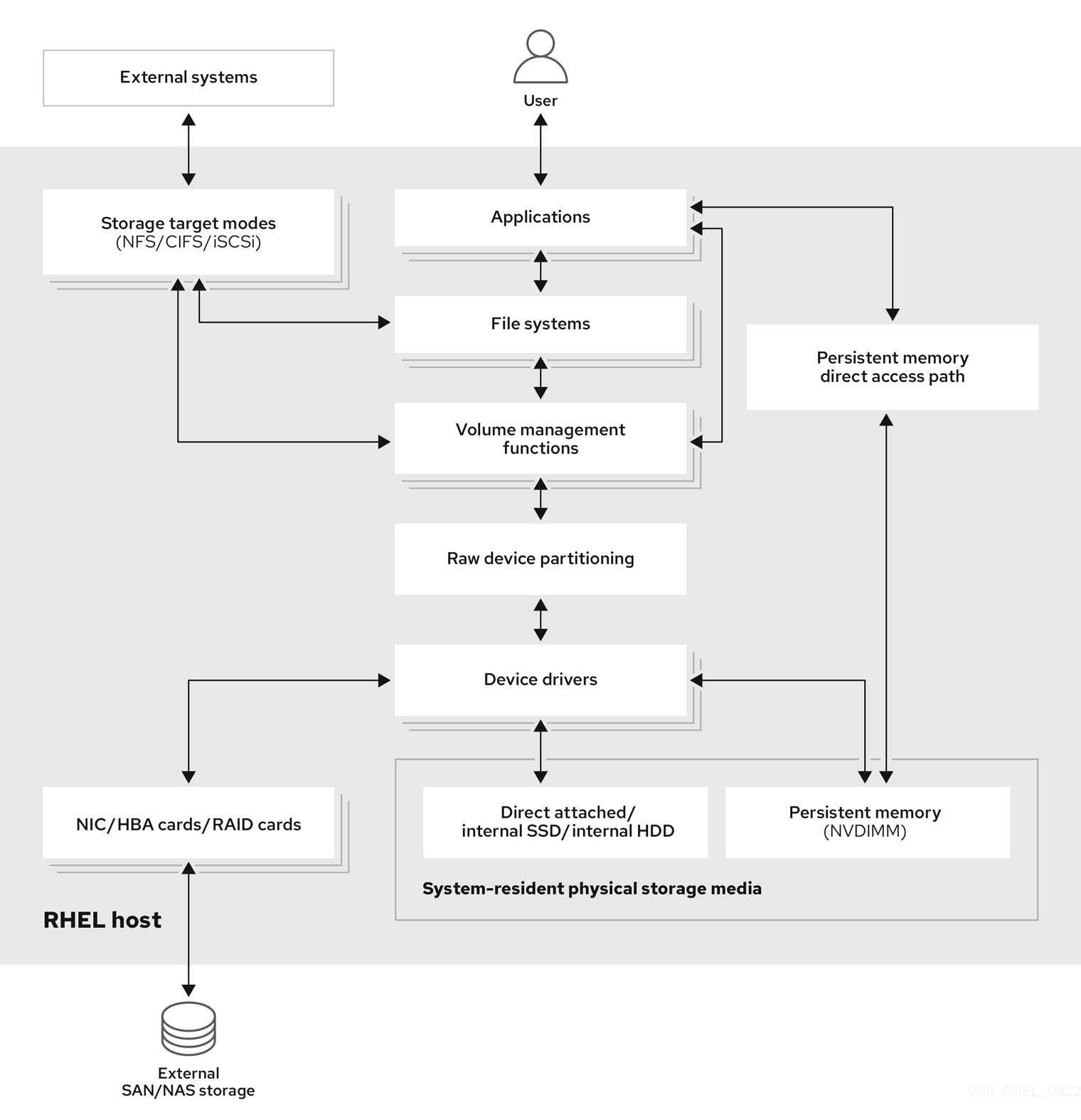
With remote storage, devices are accessed over LAN, the internet, or using a Fibre channel network. The following high level Red Hat Enterprise Linux storage diagram describes the different storage options.
Figure 1.1. High level Red Hat Enterprise Linux storage diagram
1.1. Local storage overview
Red Hat Enterprise Linux 9 offers several local storage options.
- Basic disk administration
Using
partedandfdisk, you can create, modify, delete, and view disk partitions. The following are the partitioning layout standards:- Master Boot Record (MBR)
- It is used with BIOS-based computers. You can create primary, extended, and logical partitions.
- GUID Partition Table (GPT)
- It uses globally unique identifier (GUID) and provides unique disk and partition GUID.
- Storage consumption options
- Non-Volatile Dual In-line Memory Modules (NVDIMM) Management
- It is a combination of memory and storage. You can enable and manage various types of storage on NVDIMM devices connected to your system.
- Block Storage Management
- Data is stored in the form of blocks where each block has a unique identifier.
- File Storage
- Data is stored at file level on the local system. These data can be accessed locally using XFS (default) or ext4, and over a network by using NFS and SMB.
- Logical volumes
- Logical Volume Manager (LVM)
- It creates logical devices from physical devices. Logical volume (LV) is a combination of the physical volumes (PV) and volume groups (VG).
- Virtual Data Optimizer (VDO)
It is used for data reduction by using deduplication, compression, and thin provisioning. Using LV below VDO helps in:
- Extending of VDO volume
- Spanning VDO volume over multiple devices
- Local file systems
- XFS
- The default RHEL file system.
- Ext4
- A legacy file system.
- Stratis
- Stratis is a hybrid user-and-kernel local storage management system that supports advanced storage features.
1.2. Remote storage overview
The following are the remote storage options available in RHEL 9:
- Storage connectivity options
- iSCSI
- RHEL 9 uses the targetcli tool to add, remove, view, and monitor iSCSI storage interconnects.
- Fibre Channel (FC)
RHEL 9 provides the following native Fibre Channel drivers:
-
lpfc -
qla2xxx -
Zfcp
-
- Non-volatile Memory Express (NVMe)
An interface which allows host software utility to communicate with solid state drives. Use the following types of fabric transport to configure NVMe over fabrics:
- NVMe over fabrics using Remote Direct Memory Access (NVMe/RDMA)
- NVMe over fabrics using Fibre Channel (NVMe/FC)
- NVMe over fabrics using TCP (NVMe/TCP)
- Device Mapper multipathing (DM Multipath)
- Allows you to configure multiple I/O paths between server nodes and storage arrays into a single device. These I/O paths are physical SAN connections that can include separate cables, switches, and controllers.
- Network file system
- NFS
- SMB
1.3. GFS2 file system overview
The Red Hat Global File System 2 (GFS2) file system is a 64-bit symmetric cluster file system which provides a shared name space and manages coherency between multiple nodes sharing a common block device. A GFS2 file system is intended to provide a feature set which is as close as possible to a local file system, while at the same time enforcing full cluster coherency between nodes. To achieve this, the nodes employ a cluster-wide locking scheme for file system resources. This locking scheme uses communication protocols such as TCP/IP to exchange locking information.
In a few cases, the Linux file system API does not allow the clustered nature of GFS2 to be totally transparent; for example, programs using POSIX locks in GFS2 should avoid using the GETLK function since, in a clustered environment, the process ID may be for a different node in the cluster. In most cases however, the functionality of a GFS2 file system is identical to that of a local file system.
The Red Hat Enterprise Linux Resilient Storage Add-On provides GFS2, and it depends on the Red Hat Enterprise Linux High Availability Add-On to provide the cluster management required by GFS2.
The gfs2.ko kernel module implements the GFS2 file system and is loaded on GFS2 cluster nodes.
To get the best performance from GFS2, it is important to take into account the performance considerations which stem from the underlying design. Just like a local file system, GFS2 relies on the page cache in order to improve performance by local caching of frequently used data. In order to maintain coherency across the nodes in the cluster, cache control is provided by the glock state machine.
Chapter 2. Persistent naming attributes
The way you identify and manage storage devices ensures the stability and predictability of the system. RHEL 9 uses two primary naming schemes for this purpose: traditional device names and persistent naming attributes.
Traditional device names
The Linux kernel assigns traditional device names based on the order in which they appear in the system or their enumeration. For example, the first SATA drive is usually labeled as /dev/sda, the second as /dev/sdb, and so on. While these names are straightforward, they are subject to change when devices are added or removed, the hardware configuration is modified, or the system is rebooted. This can pose challenges for scripting and configuration files. Furthermore, traditional names lack descriptive information about the purpose or characteristics of the device.
Persistent naming attributes
Persistent naming attributes (PNAs) are based on unique characteristics of the storage devices, making them more stable and predictable when presented to the system, even across system reboots. One of the key benefits of PNAs is their resilience to changes in hardware configurations, making them ideal for maintaining consistent naming conventions. When using PNAs, you can reference storage devices within scripts, configuration files, and management tools without concerns about unexpected name changes. Additionally, PNAs often include valuable metadata, such as device type or manufacturer information like combination of vendor, model name, and serial number, enhancing their descriptiveness for effective device identification and management. PNAs are eventually used to create device links in /dev/disk directory to access individual devices. The way the device link names are constructed and managed is driven by udev rules.
The following is a list of directories we can find in /dev/disk/:
Directories with content that remain unique even after system restart:
-
by-id: based on hardware attributes, with thevendor/model/serial_stringcombination. -
by-path*: Based on physical hardware placement. For devices or disks physically attached to a machine, this is the slot or port where they are connected physically to the host bus on the motherboard. However, for devices or disks attached over a network, this contains the network address specification. -
by-partlabel: Based on a label assigned to a device partition. These labels are assigned by the user. -
by-partuuid: Based on a unique number in the form ofUUIDthat is auto-generated. -
by-uuid: Based on a unique number in the form of UUID that is autogenerated.
-
Directory with content that remain unique during the current system run, but not after system restart:
-
by-diskseq:diskseq`is 'disk sequence number' that starts at 1 when the system boots. It assigns this number to a newly attached disk and each one after that gets the next number in sequence. When the system reboots, the counter restarts at 1.
-
Directories with content that are used specifically for loop devices:
-
by-loop-ref -
by-loop-inode
-
2.1. Persistent attributes for identifying file systems and block devices
In RHEL 9 storage, persistent naming attributes (PNAs) are mechanisms that provide components for consistent and reliable naming for storage devices across system reboots, hardware changes, or other events. These attributes are used to identify storage devices consistently, even if the storage devices are added, removed, or reconfigured.
PNAs are used to identify both file systems and block devices, but they serve different purposes:
- Persistent attributes for identifying file systems
Universally unique identifier (UUID)
UUIDs are primarily used to uniquely identify file systems on storage devices. Each file system instance has its own UUID assigned automatically, and this identifier remains constant even if the file system is unmounted, remounted, or the device is detached and reattached.
Label
Labels are user-assigned names for file systems. While they can be used to identify and reference file systems, they are not as standardized as UUIDs. Since a user assigns the file system label, its uniqueness depends on their choice. Labels are often used as alternatives to UUIDs to specify file systems in configuration files.
When you assign a label to a file system, it becomes part of the file system metadata. This label remains associated with the file system even if it is unmounted, remounted, or the device is detached and reattached.
- Persistent attributes for identifying block devices
Universally unique identifier (UUID)
UUIDs can be used to identify storage block devices. When a storage device is formatted, a UUID is often assigned to the device itself. Such UUIDs are usually generated and assigned to virtual block devices layered on top of other block devices, where the real devices are at the bottom level. For example, device-mapper (DM) based devices and their related subsystems, such as Logical Volume Manager (LVM) and crypt, use UUIDs for device identification, such as Logical Volume UUID (LVUUID) and crypt UUID.
Also, multiple-device (MD) based devices have UUIDs assigned. The virtual devices usually also mark the underlying devices with component UUIDs. For example, LVM marks its underlying devices with a Physical Volume UUID (PVUUID) and MD marks its underlying devices with an MD component UUID.
These UUIDs are embedded within the virtual block device metadata and they are used as persistent naming attributes. It allows you to uniquely identify the block device, even if you change the file system that resides on it. UUIDs are also assigned for device partitions.
Such UUIDs can coexist with other device IDs. For example, an sda device at the bottom of the device stack which is identified by its
vendor/model/serial_numbercombination or WWID, can also have a PVUUID assigned by LVM. This is then recognized by LVM itself to build up the Volume Group (VG) or Logical Volume (LV) in a layer above it.- Label or Name Labels or names can be assigned to certain block devices too. This applies to partitions which can have user-assigned labels. Some of the virtual block devices, like device-mapper (DM) based devices and multiple-device (MD) based devices also use names to identify devices.
World Wide Identifier (WWID)
WWID encompasses a family of identifiers which are globally unique and they are associated with storage block devices or storage components in general. They are commonly used in enterprise-level Storage Area Networks (SANs), like Fibre Channel (FC), to identify a storage node - World Wide Node Name (WWNN) or actual port/connection to a storage device on the node - World Wide Port Name (WWPN). WWIDs ensure consistent communication between servers and SAN storage devices and help manage redundant paths to storage devices.
Other types of devices may use a form of WWIDs too, like NVME devices. These devices do not necessarily need to be accessed over a network or SAN, and they do not have to be enterprise-level devices either.
The WWID format does not follow a single standard. For example, SCSI uses formats such as NAA, T10, and EUI. The NVME uses formats such as EUI-64, NGUUID, and UUID.
Serial string
The serial string is a unique string identifier assigned to each storage block device by the manufacturer. It can be used to differentiate among storage devices and may be used in combination with other attributes like UUIDs or WWIDs for device management.
Within
udev rules, and consequently in the/dev/disk/by-idcontent, the 'short serial string' typically represents the actual serial string as reported by the device itself. Whereas, 'serial string' is composed of several components, usually<bus_type>-<vendor_name>_<model_name>_<short_serial_string>.WWIDs and serial strings are preferred for real devices. For virtual devices, UUIDs or names is preferred.
2.2. udev device naming rules
Userspace device manager (udev) subsystem allows you to define rules for assigning persistent names to devices. These rules are stored in a file with a .rules extension. There are two primary locations for storing the udev rules:
-
/usr/lib/udev/rules.d/directory contains default rules that come with an installed package. -
/etc/udev/rules.ddirectory is intended for customudevrules.
If a rule from /usr/lib/udev/rules.d/ is modified, it will be overwritten by the rules file of the package during an update. Hence, any manual or custom rule should be added in /etc/udev/rules.d where it is retained until removed explicitly. Before use, udev rules from both directories are merged. If a rule in /etc/udev/rules.d has the same name as one in /usr/lib/udev/rules.d/ the one in the former takes precedence.
The purpose of these rules is to ensure that storage devices are consistently and predictably identified, even across system reboots and configuration changes.
udev rules define actions to execute based on incoming events that notify about adding, changing or removing a device. This also helps to collect values for the persistent storage attributes and direct udev to create the /dev content based on the collected information. The udev rules are written in human-readable format using key-value pairs.
In the case of storage devices, udev rules control creation of symbolic links in the /dev/disk/ directory. These symbolic links provide user-friendly aliases for storage devices, making it more convenient to refer to and manage these devices.
You can create custom udev rules to specify how devices should be named based on various attributes such as serial numbers, World Wide Name (WWN) identifiers, or other device-specific characteristics. By defining specific naming rules, you have precise control over how devices are identified within the system. To create a specific custom symbolic link in /dev for a device see the udev(7) man page on your system.
While udev rules are very flexible, it is important to be aware of udev limitations:
-
Accessibility Timing: Some storage devices might not be accessible at the time of a
udevquery. -
Event-Based Processing: The kernel can send
udevevents at any time, potentially triggering rule processing and link removal if a device is inaccessible. - Processing Delay: There might be a delay between event generation and processing, especially with numerous devices, causing a lag between kernel detection and link availability.
-
Device Accessibility: External programs invoked by
udevrules, likeblkid, might briefly open the device, making it temporarily inaccessible for other tasks. -
Link Updates: Device names managed by
udevin/dev/disk/can change between major releases, requiring link updates.
The following table lists the symlinks available in /dev/disk.
| Device type | Nonpersistent Name (Kernel Name) | Persistent Symlink Names |
|---|---|---|
| Real Devices | ||
| nvme (Non-Volatile Memory Express) | /dev/nvme* |
/dev/disk/by-id/nvme-<wwid> |
| scsi (Small Computer System Interface) | /dev/sd*, /dev/sr* |
/dev/disk/by-id/scsi-<model>_<serial> |
| ata (Advanced Technology Attachment)/atapi (ATA Packet Interface) | /dev/sd*, /dev/sr* |
/dev/disk/by-id/ata-<model>_<serial> |
| cciss (Compaq Command Interface for SCSI-3 Support) | /dev/cciss* |
/dev/disk/by-id/cciss-<model>_<serial> |
| virtio (Virtual Input Output) | /dev/vd* | /dev/disk/by-id/virtio-<serial> |
| pmem (Persistent Memory) | /dev/pmem* | /dev/disk/by-id/pmem-<uuid> |
| mmc (MultiMedia Card) | /dev/mmcblk* | /dev/disk/by-id/mmc-<name>_<serial> |
| memstick (Memory Stick) | /dev/msblk* | /dev/disk/by-id/memstick-<name>_<serial> |
| Virtual devices | ||
| loop | /dev/loop* |
/dev/disk/by-loop-inode/<id_loop_backing_device>-<id_loop_backing_inode> |
| dm (device-mapper) | /dev/dm-* |
/dev/mapper/<name> |
| md (multiple device) | /dev/md* |
/dev/md/<devname> |
| Partitions (either on top of a real or a virtual device) | ||
| (any) | (any) |
/dev/disk/by-partuuid/<uuid> |
| LVM PVs (Logical Volume Manager Physical Volumes; either on top of a real or a virtual device) | ||
| (any) | (any) | /dev/disk/by-id/lvm-pv-uuid-<pvuuid> |
2.2.1. Obtaining the device links value for an existing device
You can obtain the value of the device links for an existing device from the current udev database.
Prerequisites
- The device is present and connected to the system.
Procedure
List all the assigned device symbolic links (
DEVLINKS) to the base kernel device node (DEVNAME) under/devfor an existing device:# udevadm info --name /dev/nvme0n1 --query property --property DEVLINKS --value /dev/disk/by-path/pci-0000:00:02.0-nvme-1 /dev/disk/by-diskseq/6 /dev/disk/by-id/nvme-QEMU_NVMe_Ctrl_nvme-1_1 /dev/disk/by-id/nvme-QEMU_NVMe_Ctrl_nvme-1 /dev/disk/by-id/nvme-QEMU_NVMe_Ctrl_nvme-1-ns-1 /dev/disk/by-id/nvme-nvme.8086-6e766d652d31-51454d55204e564d65204374726c-00000001Replace nvme0n1 with your device name.
You can also obtain the base kernel name that all the devlinks point to by using the following command:
# udevadm info --name /dev/nvme0n1 --query property --property DEVNAME --value /dev/nvme0n1The kernel name and any of its devlinks can be used interchangeably.
You can use one of the devlinks to get the full list of devlinks by using the following command:
# udevadm info --name /dev/disk/by-id/nvme-nvme.8086-6e766d652d31-51454d55204e564d65204374726c-00000001 --query property --property DEVLINKS --value

/dev/disk/by-id/nvme-QEMU_NVMe_Ctrl_nvme-1
/dev/disk/by-diskseq/6
/dev/disk/by-id/nvme-nvme.8086-6e766d652d31-51454d55204e564d65204374726c-00000001
/dev/disk/by-id/nvme-QEMU_NVMe_Ctrl_nvme-1-ns-1
/dev/disk/by-id/nvme-QEMU_NVMe_Ctrl_nvme-1_1
/dev/disk/by-path/pci-0000:00:02.0-nvme-1
Chapter 3. Disk partitions
To divide a disk into one or more logical areas, use the disk partitioning utility. It enables separate management of each partition.
3.1. Overview of partitions
The hard disk stores information about the location and size of each disk partition in the partition table. Using information from the partition table, the operating system treats each partition as a logical disk. Some of the advantages of disk partitioning include:
- Reduce the likelihood of administrative oversights of Physical Volumes
- Ensure sufficient backup
- Provide efficient disk management
3.2. Comparison of partition table types
To enable partitions on a device, format a block device with different types of partition tables. The following table compares the properties of different types of partition tables that you can create on a block device.
This section does not cover the DASD partition table, which is specific to the IBM Z architecture.
| Partition table | Maximum number of partitions | Maximum partition size |
|---|---|---|
| Master Boot Record (MBR) | 4 primary, or 3 primary and 1 extended partition with 12 logical partitions |
2 TiB if using 512 b sector drives |
| GUID Partition Table (GPT) | 128 |
8 ZiB if using 512 b sector drives |
3.3. MBR disk partitions
The partition table is stored at the very start of the disk, before any file system or user data. For a more clear example, the partition table is shown as being separate in the following diagrams.
Figure 3.1. Disk with MBR partition table
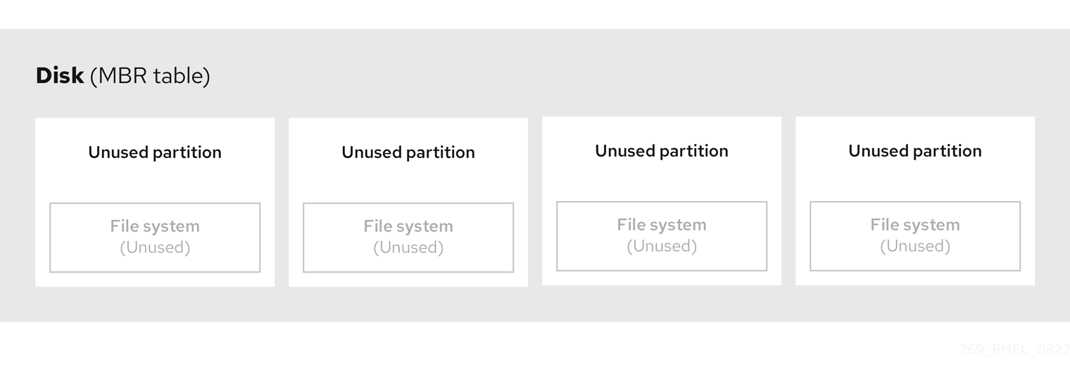
As the previous diagram shows, the partition table is divided into four sections of four unused primary partitions. A primary partition is a partition on a hard disk drive that contains only one logical drive (or section). Each logical drive holds the information necessary to define a single partition, meaning that the partition table can define no more than four primary partitions.
Each partition table entry contains important characteristics of the partition:
- The points on the disk where the partition starts and ends
-
The state of the partition, as only one partition can be flagged as
active - The type of partition
The starting and ending points define the size and location of the partition on the disk. Some of the operating systems boot loaders use the active flag. That means that the operating system in the partition that is marked "active" is booted.
The type is a number that identifies the anticipated usage of a partition. Some operating systems use the partition type to:
- Denote a specific file system type
- Flag the partition as being associated with a particular operating system
- Indicate that the partition contains a bootable operating system
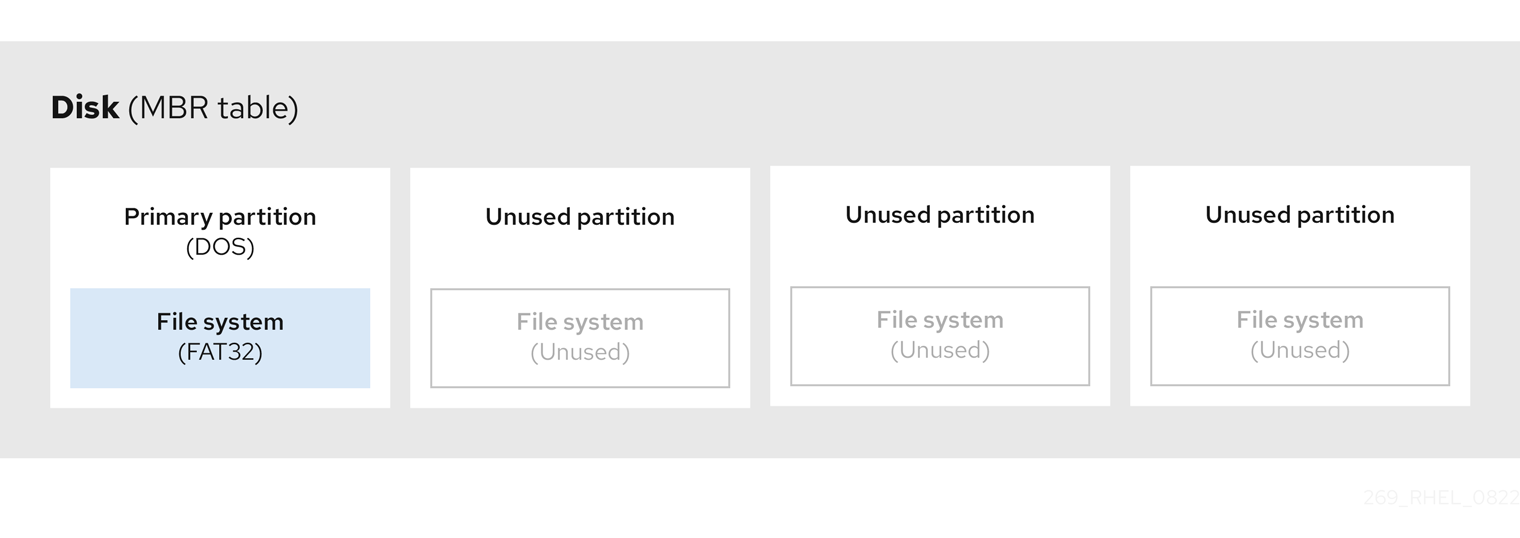
The following diagram shows an example of a drive with a single partition. In this example, the first partition is labeled as DOS partition type:
Figure 3.2. Disk with a single partition
3.4. Extended MBR partitions
To create additional partitions, if needed, set the type to extended.
An extended partition is similar to a disk drive. It has its own partition table, which points to one or more logical partitions, contained entirely within the extended partition. The following diagram shows a disk drive with two primary partitions, and one extended partition containing two logical partitions, along with some unpartitioned free space.
Figure 3.3. Disk with both two primary and an extended MBR partitions

You can have only up to four primary and extended partitions, but there is no fixed limit to the number of logical partitions. As a limit in Linux to access partitions, a single disk drive allows maximum 15 partitions.
3.5. MBR partition types
The table below shows a list of some of the most commonly used MBR partition types and hexadecimal numbers to represent them.
| MBR partition type | Value | MBR partition type | Value |
| Empty | 00 | Novell Netware 386 | 65 |
| DOS 12-bit FAT | 01 | PIC/IX | 75 |
| XENIX root | O2 | Old MINIX | 80 |
| XENIX usr | O3 | Linux/MINUX | 81 |
| DOS 16-bit ⇐32M | 04 | Linux swap | 82 |
| Extended | 05 | Linux native | 83 |
| DOS 16-bit >=32 | 06 | Linux extended | 85 |
| OS/2 HPFS | 07 | Amoeba | 93 |
| AIX | 08 | Amoeba BBT | 94 |
| AIX bootable | 09 | BSD/386 | a5 |
| OS/2 Boot Manager | 0a | OpenBSD | a6 |
| Win95 FAT32 | 0b | NEXTSTEP | a7 |
| Win95 FAT32 (LBA) | 0c | BSDI fs | b7 |
| Win95 FAT16 (LBA) | 0e | BSDI swap | b8 |
| Win95 Extended (LBA) | 0f | Syrinx | c7 |
| Venix 80286 | 40 | CP/M | db |
| Novell | 51 | DOS access | e1 |
| PRep Boot | 41 | DOS R/O | e3 |
| GNU HURD | 63 | DOS secondary | f2 |
| Novell Netware 286 | 64 | BBT | ff |
3.6. GUID partition table
The GUID partition table (GPT) is a partitioning scheme based on the Globally Unique Identifier (GUID).
GPT deals with the limitations of the Mater Boot Record (MBR) partition table. The MBR partition table cannot address storage larger than 2 TiB, equal to approximately 2.2 TB. Instead, GPT supports hard disks with larger capacity. The maximum addressable disk size is 8 ZiB, when using 512b sector drives, and 64 ZiB, when using 4096b sector drives. In addition, by default, GPT supports creation of up to 128 primary partitions. Extend the maximum amount of primary partitions by allocating more space to the partition table.
A GPT has partition types based on GUIDs. Certain partitions require a specific GUID. For example, the system partition for Extensible Firmware Interface (EFI) boot loaders require GUID C12A7328-F81F-11D2-BA4B-00A0C93EC93B.
GPT disks use logical block addressing (LBA) and a partition layout as follows:
- For backward compatibility with MBR disks, the system reserves the first sector (LBA 0) of GPT for MBR data, and applies the name "protective MBR".
Primary GPT
- The header begins on the second logical block (LBA 1) of the device. The header contains the disk GUID, the location of the primary partition table, the location of the secondary GPT header, and CRC32 checksums of itself, and the primary partition table. It also specifies the number of partition entries on the table.
- By default, the primary GPT includes 128 partition entries. Each partition has an entry size of 128 bytes, a partition type GUID and a unique partition GUID.
Secondary GPT
- For recovery, it is useful as a backup table in case the primary partition table is corrupted.
- The last logical sector of the disk contains the secondary GPT header and recovers GPT information, in case the primary header is corrupted.
It contains:
- The disk GUID
- The location of the secondary partition table and the primary GPT header
- CRC32 checksums of itself
- The secondary partition table
- The number of possible partition entries
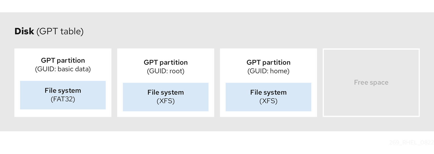
Figure 3.4. Disk with a GUID Partition Table
For a successful installation of the boot loader onto a GPT disk a BIOS boot partition must be present. Reuse is possible only if the disk already contains a BIOS boot partition. This includes disks initialized by the Anaconda installation program.
3.7. Partition types
There are multiple ways to manage partition types:
-
The
fdiskutility supports the full range of partition types by specifying hexadecimal codes. -
The
systemd-gpt-auto-generator, a unit generator utility, uses the partition type to automatically identify and mount devices. The
partedutility maps out the partition type with flags. Thepartedutility handles only certain partition types, for example LVM, swap or RAID.The
partedutility supports setting the following flags:-
boot -
root -
swap -
hidden -
raid -
lvm -
lba -
legacy_boot -
irst -
esp -
palo
-
On Red Hat Enterprise Linux 9 with parted 3.5, you can use the additional flags chromeos_kernel and bls_boot.
The parted utility optionally accepts a file system type argument while creating a partition. For a list of the required conditions, see Creating a partition with parted. Use the value to:
- Set the partition flags on MBR.
-
Set the partition UUID type on GPT. For example, the
swap,fat, orhfsfile system types set different GUIDs. The default value is the Linux Data GUID.
The argument does not modify the file system on the partition. It only differentiates between the supported flags and GUIDs.
The following file system types are supported:
-
xfs -
ext2 -
ext3 -
ext4 -
fat16 -
fat32 -
hfs -
hfs+ -
linux-swap -
ntfs -
reiserfs
3.8. Partition naming scheme
Red Hat Enterprise Linux uses a file-based naming scheme, with file names in the form of /dev/xxyN.
Device and partition names consist of the following structure:
/dev/-
Name of the directory that contains all device files. Hard disks contain partitions, thus the files representing all possible partitions are located in
/dev. xx- The first two letters of the partition name indicate the type of device that contains the partition.
y-
This letter indicates the specific device containing the partition. For example,
/dev/sdafor the first hard disk and/dev/sdbfor the second. You can use more letters in systems with more than 26 drives, for example,/dev/sdaa1. N-
The final letter indicates the number to represent the partition. The first four (primary or extended) partitions are numbered
1through4. Logical partitions start at5. For example,/dev/sda3is the third primary or extended partition on the first hard disk, and/dev/sdb6is the second logical partition on the second hard disk. Drive partition numbering applies only to MBR partition tables. Note that N does not always mean partition.
Even if Red Hat Enterprise Linux can identify and refer to all types of disk partitions, it might not be able to read the file system and therefore access stored data on every partition type. However, in many cases, it is possible to successfully access data on a partition dedicated to another operating system.
3.9. Mount points and disk partitions
In Red Hat Enterprise Linux, each partition forms a part of the storage, necessary to support a single set of files and directories. Mounting a partition makes the storage of that partition available, starting at the specified directory known as a mount point.
For example, if partition /dev/sda5 is mounted on /usr/, it means that all files and directories under /usr/ physically reside on /dev/sda5. The file /usr/share/doc/FAQ/txt/Linux-FAQ resides on /dev/sda5, while the file /etc/gdm/custom.conf does not.
Continuing the example, it is also possible that one or more directories below /usr/ would be mount points for other partitions. For example, /usr/local/man/whatis resides on /dev/sda7, rather than on /dev/sda5, if /usr/local includes a mounted /dev/sda7 partition.
Chapter 4. Getting started with partitions
Use disk partitioning to divide a disk into one or more logical areas which enables work on each partition separately. The hard disk stores information about the location and size of each disk partition in the partition table. Using the table, each partition then appears as a logical disk to the operating system. You can then read and write on those individual disks.
For an overview of the advantages and disadvantages to using partitions on block devices, see the Red Hat Knowledgebase solution What are the advantages and disadvantages to using partitioning on LUNs, either directly or with LVM in between?.
4.1. Creating a partition table on a disk with parted
Use the parted utility to format a block device with a partition table more easily.
Formatting a block device with a partition table deletes all data stored on the device.
Procedure
Start the interactive
partedshell:# parted block-deviceDetermine if there already is a partition table on the device:
(parted) printIf the device already contains partitions, they will be deleted in the following steps.
Create the new partition table:
(parted) mklabel table-typeReplace table-type with with the intended partition table type:
-
msdosfor MBR -
gptfor GPT
-
Example 4.1. Creating a GUID Partition Table (GPT) table
To create a GPT table on the disk, use:
(parted) mklabel gptThe changes start applying after you enter this command.
View the partition table to confirm that it is created:
(parted) printExit the
partedshell:(parted) quit
4.2. Viewing the partition table with parted
Display the partition table of a block device to see the partition layout and details about individual partitions. You can view the partition table on a block device using the parted utility.
Procedure
Start the
partedutility. For example, the following output lists the device/dev/sda:# parted /dev/sdaView the partition table:
(parted) print

Model: ATA SAMSUNG MZNLN256 (scsi)
Disk /dev/sda: 256GB
Sector size (logical/physical): 512B/512B
Partition Table: msdos
Disk Flags:

Number  Start   End     Size    Type      File system  Flags
 1      1049kB  269MB   268MB   primary   xfs          boot
 2      269MB   34.6GB  34.4GB  primary
 3      34.6GB  45.4GB  10.7GB  primary
 4      45.4GB  256GB   211GB   extended
 5      45.4GB  256GB   211GB   logical
Optional: Switch to the device you want to examine next:
(parted) select block-device
For a detailed description of the print command output, see the following:
Model: ATA SAMSUNG MZNLN256 (scsi)- The disk type, manufacturer, model number, and interface.
Disk /dev/sda: 256GB- The file path to the block device and the storage capacity.
Partition Table: msdos- The disk label type.
Number-
The partition number. For example, the partition with minor number 1 corresponds to
/dev/sda1. StartandEnd- The location on the device where the partition starts and ends.
Type- Valid types are metadata, free, primary, extended, or logical.
File system-
The file system type. If the
File systemfield of a device shows no value, this means that its file system type is unknown. Thepartedutility cannot recognize the file system on encrypted devices. Flags-
Lists the flags set for the partition. Available flags are
boot,root,swap,hidden,raid,lvm, orlba.
4.3. Creating a partition with parted
As a system administrator, you can create new partitions on a disk by using the parted utility.
The required partitions are swap, /boot/, and / (root).
Prerequisites
- A partition table on the disk.
- If the partition you want to create is larger than 2TiB, format the disk with the GUID Partition Table (GPT).
Procedure
Start the
partedutility:# parted block-deviceView the current partition table to determine if there is enough free space:
(parted) print- Resize the partition in case there is not enough free space.
From the partition table, determine:
- The start and end points of the new partition.
- On MBR, what partition type it should be.
Create the new partition:
(parted) mkpart part-type name fs-type start end-
Replace part-type with with
primary,logical, orextended. This applies only to the MBR partition table. - Replace name with an arbitrary partition name. This is required for GPT partition tables.
-
Replace fs-type with
xfs,ext2,ext3,ext4,fat16,fat32,hfs,hfs+,linux-swap,ntfs, orreiserfs. The fs-type parameter is optional. Note that thepartedutility does not create the file system on the partition. -
Replace start and end with the sizes that determine the starting and ending points of the partition, counting from the beginning of the disk. You can use size suffixes, such as
512MiB,20GiB, or1.5TiB. The default size is in megabytes.
Example 4.2. Creating a small primary partition
To create a primary partition from 1024MiB until 2048MiB on an MBR table, use:
(parted) mkpart primary 1024MiB 2048MiBThe changes start applying after you enter the command.
-
Replace part-type with with
View the partition table to confirm that the created partition is in the partition table with the correct partition type, file system type, and size:
(parted) printExit the
partedshell:(parted) quitRegister the new device node:
# udevadm settleVerify that the kernel recognizes the new partition:
# cat /proc/partitions
4.4. Setting a partition type with fdisk
You can set a partition type or flag, using the fdisk utility.
Prerequisites
- A partition on the disk.
Procedure
Start the interactive
fdiskshell:# fdisk block-deviceView the current partition table to determine the minor partition number:
Command (m for help): printYou can see the current partition type in the
Typecolumn and its corresponding type ID in theIdcolumn.Enter the partition type command and select a partition using its minor number:
Command (m for help): type
Partition number (1,2,3 default 3): 2
Optional: View the list in hexadecimal codes:
Hex code (type L to list all codes): LSet the partition type:
Hex code (type L to list all codes): 8eWrite your changes and exit the
fdiskshell:Command (m for help): write The partition table has been altered. Syncing disks.Verify your changes:
# fdisk --list block-device
4.5. Resizing a partition with parted
Using the parted utility, extend a partition to use unused disk space, or shrink a partition to use its capacity for different purposes.
Prerequisites
- Back up the data before shrinking a partition.
- If the partition you want to create is larger than 2TiB, format the disk with the GUID Partition Table (GPT).
- If you want to shrink the partition, first shrink the file system so that it is not larger than the resized partition.
XFS does not support shrinking.
Procedure
Start the
partedutility:# parted block-deviceView the current partition table:
(parted) printFrom the partition table, determine:
- The minor number of the partition.
- The location of the existing partition and its new ending point after resizing.
Resize the partition:
(parted) resizepart 1 2GiB- Replace 1 with the minor number of the partition that you are resizing.
-
Replace 2 with the size that determines the new ending point of the resized partition, counting from the beginning of the disk. You can use size suffixes, such as
512MiB,20GiB, or1.5TiB. The default size is in megabytes.
View the partition table to confirm that the resized partition is in the partition table with the correct size:
(parted) printExit the
partedshell:(parted) quitVerify that the kernel registers the new partition:
# cat /proc/partitions- Optional: If you extended the partition, extend the file system on it as well.
4.6. Removing a partition with parted
Using the parted utility, you can remove a disk partition to free up disk space.
Procedure
Start the interactive
partedshell:# parted block-device-
Replace block-device with the path to the device where you want to remove a partition: for example,
/dev/sda.
-
Replace block-device with the path to the device where you want to remove a partition: for example,
View the current partition table to determine the minor number of the partition to remove:
(parted) printRemove the partition:
(parted) rm minor-number- Replace minor-number with the minor number of the partition you want to remove.
The changes start applying as soon as you enter this command.
Verify that you have removed the partition from the partition table:
(parted) printExit the
partedshell:(parted) quitVerify that the kernel registers that the partition is removed:
# cat /proc/partitions-
Remove the partition from the
/etc/fstabfile, if it is present. Find the line that declares the removed partition, and remove it from the file. Regenerate mount units so that your system registers the new
/etc/fstabconfiguration:# systemctl daemon-reloadIf you have deleted a swap partition or removed pieces of LVM, remove all references to the partition from the kernel command line:
List active kernel options and see if any option references the removed partition:
# grubby --info=ALLRemove the kernel options that reference the removed partition:
# grubby --update-kernel=ALL --remove-args="option"
To register the changes in the early boot system, rebuild the
initramfsfile system:# dracut --force --verbose
Chapter 5. Strategies for repartitioning a disk
There are different approaches to repartitioning a disk. These include:
- Unpartitioned free space is available.
- An unused partition is available.
- Free space in an actively used partition is available.
The following examples are simplified for clarity and do not reflect the exact partition layout when actually installing Red Hat Enterprise Linux.
5.1. Using unpartitioned free space
Partitions that are already defined and do not span the entire hard disk, leave unallocated space that is not part of any defined partition. The following diagram shows what this might look like.
Figure 5.1. Disk with unpartitioned free space

The first diagram represents a disk with one primary partition and an undefined partition with unallocated space. The second diagram represents a disk with two defined partitions with allocated space.
An unused hard disk also falls into this category. The only difference is that all the space is not part of any defined partition.
On a new disk, you can create the necessary partitions from the unused space. Most preinstalled operating systems are configured to take up all available space on a disk drive.
5.2. Using space from an unused partition
In the following example, the first diagram represents a disk with an unused partition. The second diagram represents reallocating an unused partition for Linux.
Figure 5.2. Disk with an unused partition
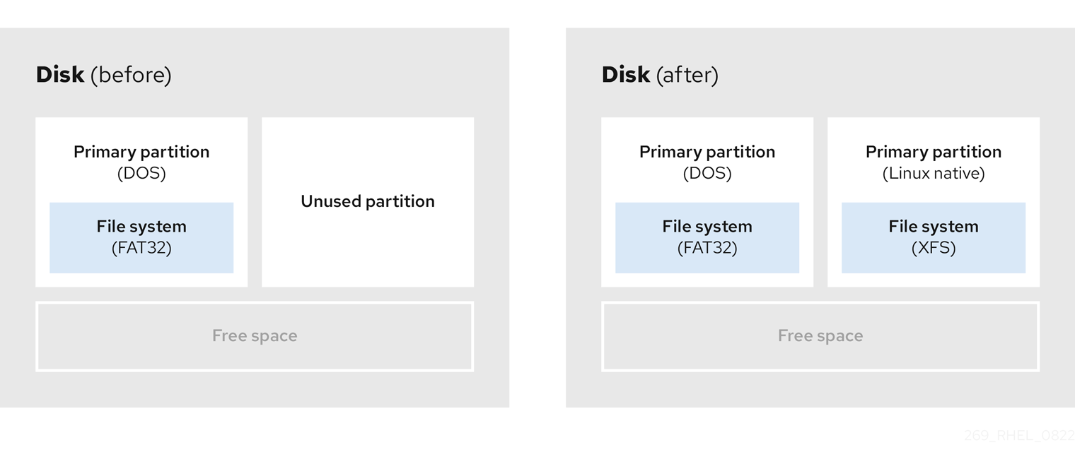
To use the space allocated to the unused partition, delete the partition and then create the appropriate Linux partition instead. Alternatively, during the installation process, delete the unused partition and manually create new partitions.
5.3. Using free space from an active partition
This process can be difficult to manage because an active partition, that is already in use, contains the required free space. In most cases, hard disks of computers with preinstalled software contain one larger partition holding the operating system and data.
If you want to use an operating system (OS) on an active partition, you must reinstall the OS. Be aware that some computers, which include pre-installed software, do not include installation media to reinstall the original OS. Check whether this applies to your OS before you destroy an original partition and the OS installation.
To optimise the use of available free space, you can use the methods of destructive or non-destructive repartitioning.
5.3.1. Destructive repartitioning
Destructive repartitioning destroys the partition on your hard drive and creates several smaller partitions instead. Backup any needed data from the original partition as this method deletes the complete contents.
After creating a smaller partition for your existing operating system, you can:
- Reinstall software.
- Restore your data.
- Start your Red Hat Enterprise Linux installation.
The following diagram is a simplified representation of using the destructive repartitioning method.
Figure 5.3. Destructive repartitioning action on disk
This method deletes all data previously stored in the original partition.
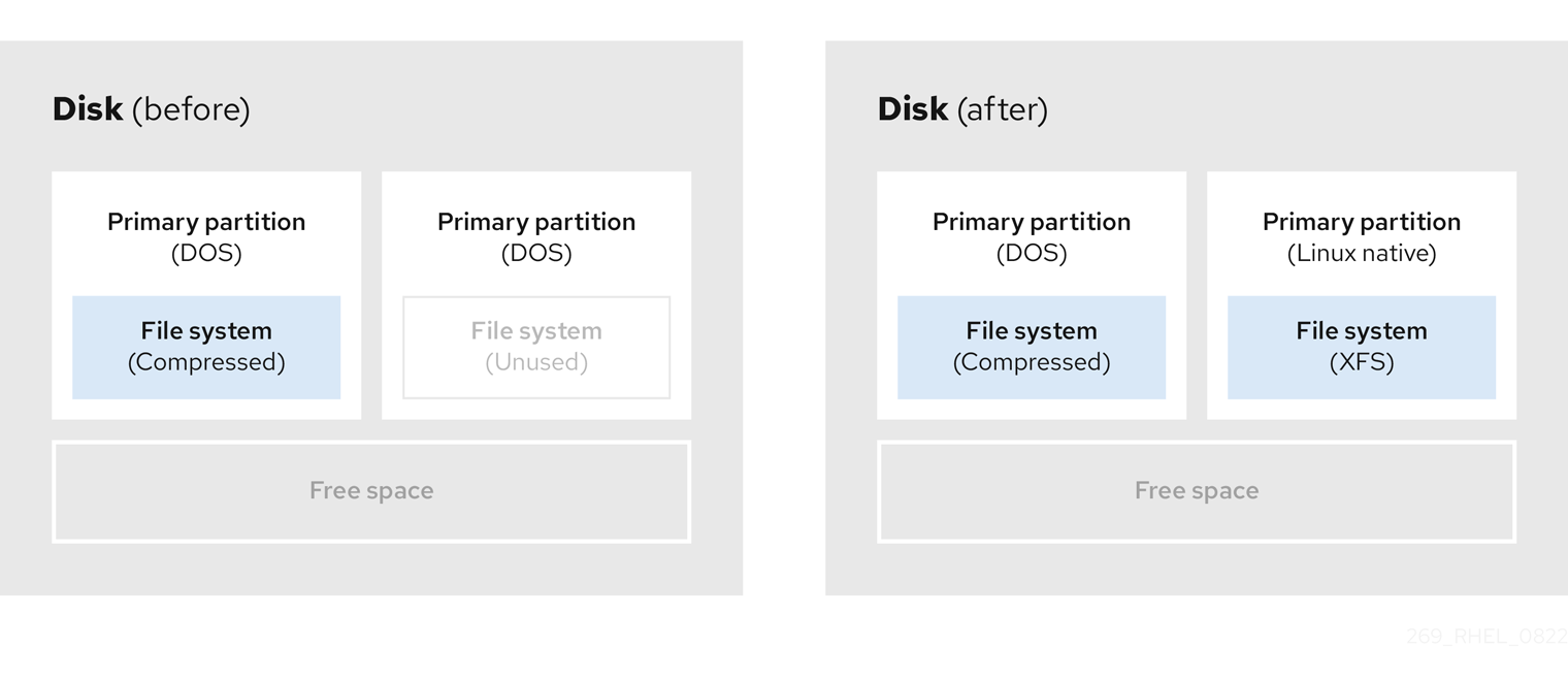
5.3.2. Non-destructive repartitioning
Non-destructive repartitioning resizes partitions, without any data loss. This method is reliable, however it takes longer processing time on large drives.
The following is a list of methods, which can help initiate non-destructive repartitioning.
- Compress existing data
The storage location of some data cannot be changed. This can prevent the resizing of a partition to the required size, and ultimately lead to a destructive repartition process. Compressing data in an already existing partition can help you resize your partitions as needed. It can also help to maximize the free space available.
The following diagram is a simplified representation of this process.
Figure 5.4. Data compression on a disk
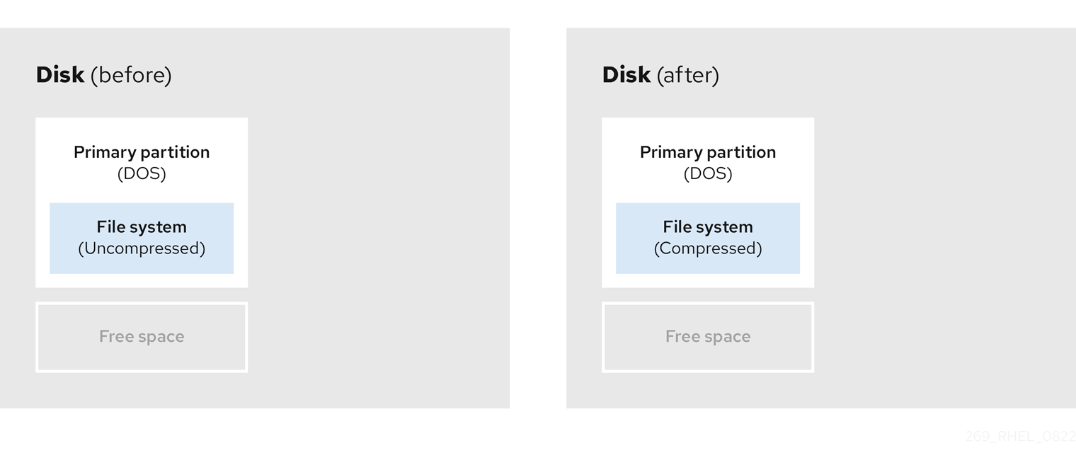
To avoid any possible data loss, create a backup before continuing with the compression process.
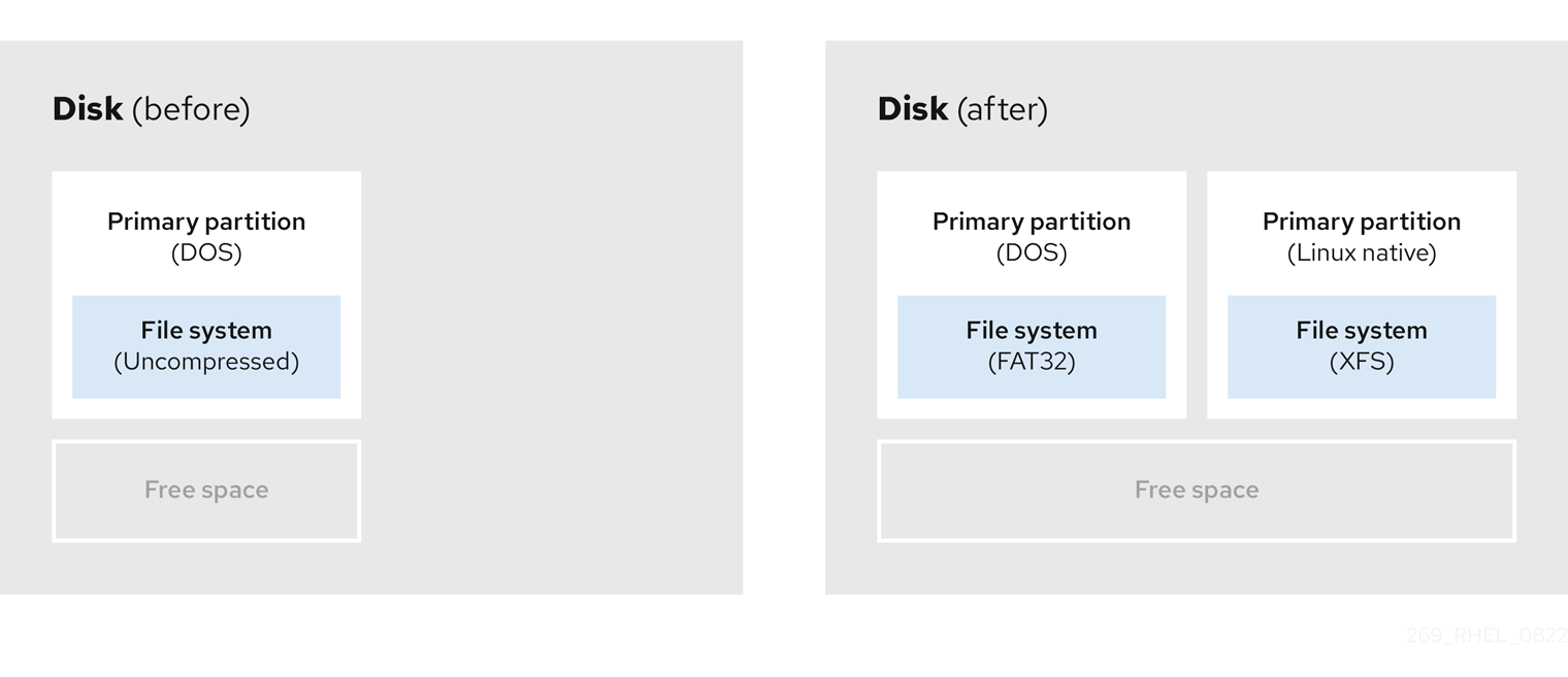
- Resize the existing partition
By resizing an already existing partition, you can free up more space. Depending on your resizing software, the results may vary. In the majority of cases, you can create a new unformatted partition of the same type, as the original partition.
The steps you take after resizing can depend on the software you use. In the following example, the best practice is to delete the new DOS (Disk Operating System) partition, and create a Linux partition instead. Verify what is most suitable for your disk before initiating the resizing process.
Figure 5.5. Partition resizing on a disk
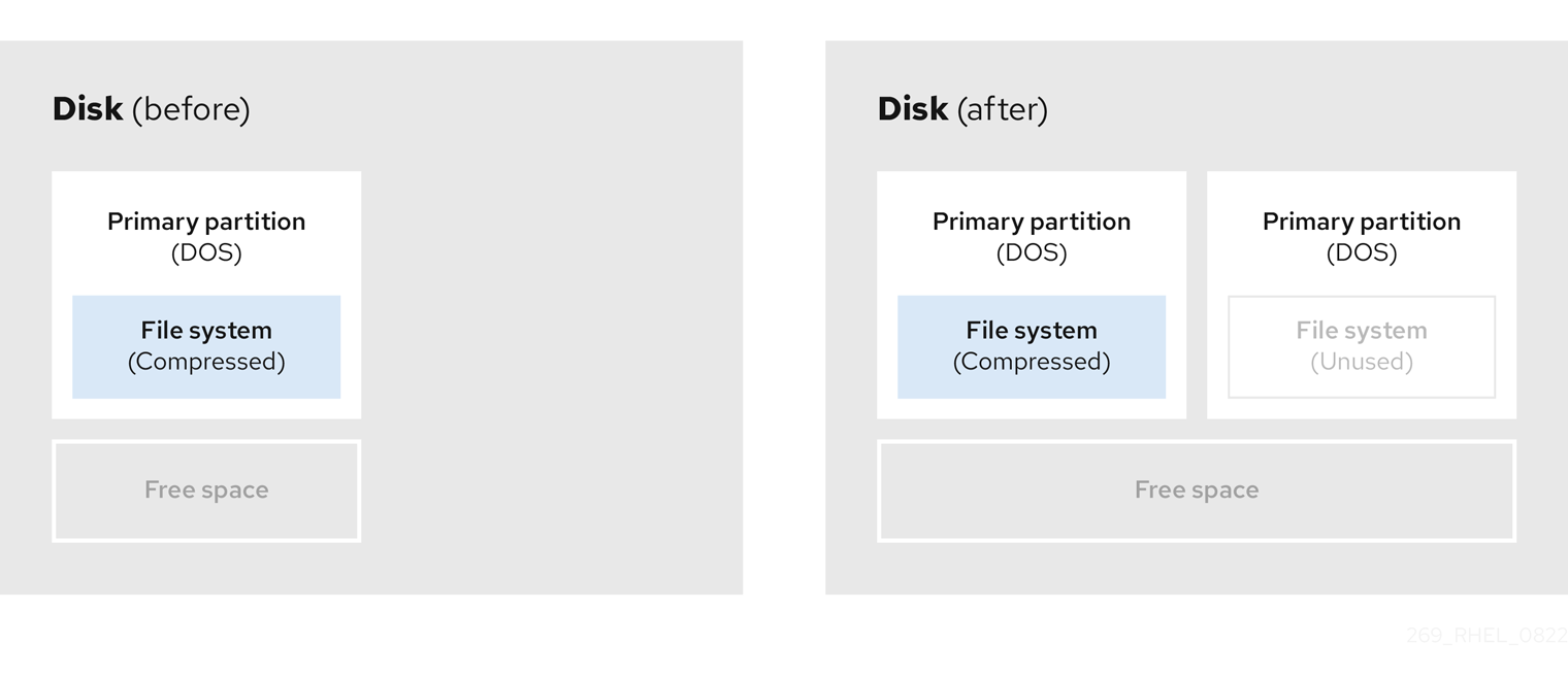
- Optional: Create new partitions
Some pieces of resizing software support Linux based systems. In such cases, there is no need to delete the newly created partition after resizing. Creating a new partition afterwards depends on the software you use.
The following diagram represents the disk state, before and after creating a new partition.
Figure 5.6. Disk with final partition configuration
Chapter 6. Configuring an iSCSI target
Red Hat Enterprise Linux uses the targetcli shell as a command-line interface to perform the following operations:
- Add, remove, view, and monitor iSCSI storage interconnects to utilize iSCSI hardware.
- Export local storage resources that are backed by either files, volumes, local SCSI devices, or by RAM disks to remote systems.
The targetcli tool has a tree-based layout including built-in tab completion, auto-complete support, and inline documentation.
6.1. Installing targetcli
Install the targetcli tool to add, monitor, and remove iSCSI storage interconnects .
Procedure
Install the
targetclitool:# dnf install targetcliStart the target service:
# systemctl start targetConfigure target to start at boot time:
# systemctl enable targetOpen port
3260in the firewall and reload the firewall configuration:# firewall-cmd --permanent --add-port=3260/tcp Success# firewall-cmd --reload Success
Verification
View the
targetclilayout:# targetcli /> ls o- /........................................[...] o- backstores.............................[...] | o- block.................[Storage Objects: 0] | o- fileio................[Storage Objects: 0] | o- pscsi.................[Storage Objects: 0] | o- ramdisk...............[Storage Objects: 0] o- iscsi...........................[Targets: 0] o- loopback........................[Targets: 0]
6.2. Creating an iSCSI target
You can create an iSCSI target to let the iSCSI initiator of the client to access the storage devices on the server. Both targets and initiators have unique identifying names.
Prerequisites
-
Installed and running
targetcli. For more information, see Installing targetcli.
Procedure
Navigate to the iSCSI directory. You can also use the
cdcommand to navigate to the iSCSI directory./> iscsi/Use one of the following options to create an iSCSI target:
Creating an iSCSI target using a default target name:
/iscsi> create

Created target
iqn.2003-01.org.linux-iscsi.hostname.x8664:sn.78b473f296ff
Created TPG1
Creating an iSCSI target using a specific name:
/iscsi> create iqn.2006-04.com.example:444

Created target iqn.2006-04.com.example:444
Created TPG1
Here iqn.2006-04.com.example:444 is target_iqn_name
Replace iqn.2006-04.com.example:444 with the specific target name.
Verify the newly created target:
/iscsi> ls

o- iscsi.......................................[1 Target]
    o- iqn.2006-04.com.example:444................[1 TPG]
        o- tpg1...........................[enabled, auth]
           o- acls...............................[0 ACL]
            o- luns...............................[0 LUN]
           o- portals.........................[0 Portal]
6.3. iSCSI Backstore
An iSCSI backstore enables support for different methods of storing an exported LUN’s data on the local machine. Creating a storage object defines the resources that the backstore uses.
An administrator can choose any of the following backstore devices that Linux-IO (LIO) supports:
fileiobackstore-
Create a
fileiostorage object if you are using regular files on the local file system as disk images. For creating afileiobackstore, see Creating a fileio storage object. blockbackstore-
Create a
blockstorage object if you are using any local block device and logical device. For creating ablockbackstore, see Creating a block storage object. pscsibackstore-
Create a
pscsistorage object if your storage object supports direct pass-through of SCSI commands. For creating apscsibackstore, see Creating a pscsi storage object. ramdiskbackstore-
Create a
ramdiskstorage object if you want to create a temporary RAM backed device. For creating aramdiskbackstore, see Creating a Memory Copy RAM disk storage object.
6.4. Creating a fileio storage object
fileio storage objects can support either the write_back or write_thru operations. The write_back operation enables the local file system cache. This improves performance but increases the risk of data loss.
It is recommended to use write_back=false to disable the write_back operation in favor of the write_thru operation.
Prerequisites
-
Installed and running
targetcli. For more information, see Installing targetcli.
Procedure
Navigate to the
fileio/from thebackstores/directory:/> backstores/fileioCreate a
fileiostorage object:/backstores/fileio> create file1 /tmp/disk1.img 200M write_back=false Created fileio file1 with size 209715200
Verification
Verify the created
fileiostorage object:/backstores/fileio> ls
6.5. Creating a block storage object
The block driver allows the use of any block device that appears in the /sys/block/ directory to be used with Linux-IO (LIO). This includes physical devices, such as HDDs, SSDs, CDs, and DVDs, and logical devices, such as software or hardware RAID volumes, or LVM volumes.
Prerequisites
-
Installed and running
targetcli. For more information, see Installing targetcli.
Procedure
Navigate to the
block/from thebackstores/directory:/> backstores/block/Create a
blockbackstore:/backstores/block> create name=block_backend dev=/dev/sdb Generating a wwn serial. Created block storage object block_backend using /dev/sdb.
Verification
Verify the created
blockstorage object:/backstores/block> ls
6.6. Creating a pscsi storage object
You can configure as a backstore any storage object that supports direct pass-through of SCSI commands without SCSI emulation and with an underlying SCSI device that appears with lsscsi in the /proc/scsi/scsi, such as a SAS hard drive. SCSI-3 and higher is supported with this subsystem.
pscsi should only be used by advanced users. Advanced SCSI commands such as for Asymmetric Logical Unit Assignment (ALUAs) or Persistent Reservations (for example, those used by VMware ESX, and vSphere) are usually not implemented in the device firmware and can cause malfunctions or crashes. When in doubt, use block backstore for production setups instead.
Prerequisites
-
Installed and running
targetcli. For more information, see Installing targetcli.
Procedure
Navigate to the
pscsi/from thebackstores/directory:/> backstores/pscsi/Create a
pscsibackstore for a physical SCSI device, a TYPE_ROM device using/dev/sr0in this example:/backstores/pscsi> create name=pscsi_backend dev=/dev/sr0 Generating a wwn serial. Created pscsi storage object pscsi_backend using /dev/sr0
Verification
Verify the created
pscsistorage object:/backstores/pscsi> ls
6.7. Creating a Memory Copy RAM disk storage object
Memory Copy RAM disks (ramdisk) provide RAM disks with full SCSI emulation and separate memory mappings using memory copy for initiators. This provides capability for multi-sessions and is particularly useful for fast and volatile mass storage for production purposes.
Prerequisites
-
Installed and running
targetcli. For more information, see Installing targetcli.
Procedure
Navigate to the
ramdisk/from thebackstores/directory:/> backstores/ramdisk/Create a 1GB RAM disk backstore:
/backstores/ramdisk> create name=rd_backend size=1GB

Generating a wwn serial.
Created rd_mcp ramdisk rd_backend with size 1GB.
Verification
Verify the created
ramdiskstorage object:/backstores/ramdisk> ls
6.8. Creating an iSCSI portal
You can create an iSCSI portal. This adds an IP address and a port to the target that keeps the target enabled.
Prerequisites
-
Installed and running
targetcli. For more information, see Installing targetcli. - An iSCSI target associated with a Target Portal Groups (TPG). For more information, see Creating an iSCSI target.
Procedure
Navigate to the TPG directory:
/iscsi> iqn.2006-04.com.example:444/tpg1/Use one of the following options to create an iSCSI portal:
Creating a default portal uses the default iSCSI port
3260and allows the target to listen to all IP addresses on that port:/iscsi/iqn.20...mple:444/tpg1> portals/ create Using default IP port 3260 Binding to INADDR_Any (0.0.0.0) Created network portal 0.0.0.0:3260Creating a portal using a specific IP address:
/iscsi/iqn.20...mple:444/tpg1> portals/ create 192.168.122.137

Using default IP port 3260
Created network portal 192.168.122.137:3260
Verification
Verify the newly created portal:
/iscsi/iqn.20...mple:444/tpg1> ls

o- tpg.................................. [enabled, auth]
    o- acls ......................................[0 ACL]
    o- luns ......................................[0 LUN]
    o- portals ................................[1 Portal]
       o- 192.168.122.137:3260......................[OK]
6.9. Creating an iSCSI LUN
Logical unit number (LUN) is a physical device that is backed by the iSCSI backstore. Each LUN has a unique number.
Prerequisites
-
Installed and running
targetcli. For more information, see Installing targetcli. - An iSCSI target associated with a Target Portal Groups (TPG). For more information, see Creating an iSCSI target.
- Created storage objects. For more information, see iSCSI Backstore.
Procedure
Create LUNs of already created storage objects:
/iscsi/iqn.20...mple:444/tpg1> luns/ create /backstores/ramdisk/rd_backend
Created LUN 0.

/iscsi/iqn.20...mple:444/tpg1> luns/ create /backstores/block/block_backend
Created LUN 1.

/iscsi/iqn.20...mple:444/tpg1> luns/ create /backstores/fileio/file1
Created LUN 2.
Verify the created LUNs:
/iscsi/iqn.20...mple:444/tpg1> ls

o- tpg.................................. [enabled, auth]
    o- acls ......................................[0 ACL]
    o- luns .....................................[3 LUNs]
    |  o- lun0.........................[ramdisk/ramdisk1]
    |  o- lun1.................[block/block1 (/dev/vdb1)]
    |  o- lun2...................[fileio/file1 (/foo.img)]
    o- portals ................................[1 Portal]
        o- 192.168.122.137:3260......................[OK]
Default LUN name starts at
0.ImportantBy default, LUNs are created with read-write permissions. If a new LUN is added after ACLs are created, LUN automatically maps to all available ACLs and can cause a security risk. To create a LUN with read-only permissions, see Creating a read-only iSCSI LUN.
- Configure ACLs. For more information, see Creating an iSCSI ACL.
6.10. Creating a read-only iSCSI LUN
By default, LUNs are created with read-write permissions. You can create a read-only LUN.
Prerequisites
-
Installed and running
targetcli. For more information, see Installing targetcli. - An iSCSI target associated with a Target Portal Groups (TPG). For more information, see Creating an iSCSI target.
- Created storage objects. For more information, see iSCSI Backstore.
Procedure
Set read-only permissions:
/> set global auto_add_mapped_luns=false

Parameter auto_add_mapped_luns is now 'false'.
This prevents the auto mapping of LUNs to existing ACLs allowing the manual mapping of LUNs.
Navigate to the initiator_iqn_name directory:
/> iscsi/target_iqn_name/tpg1/acls/initiator_iqn_name/Create the LUN:
/iscsi/target_iqn_name/tpg1/acls/initiator_iqn_name> create mapped_lun=next_sequential_LUN_number tpg_lun_or_backstore=backstore write_protect=1Example:
/iscsi/target_iqn_name/tpg1/acls/2006-04.com.example:888> create mapped_lun=1 tpg_lun_or_backstore=/backstores/block/block2 write_protect=1

Created LUN 1.
Created Mapped LUN 1.
Verify the created LUN:
/iscsi/target_iqn_name/tpg1/acls/2006-04.com.example:888> ls
 o- 2006-04.com.example:888 .. [Mapped LUNs: 2]
 | o- mapped_lun0 .............. [lun0 block/disk1 (rw)]
 | o- mapped_lun1 .............. [lun1 block/disk2 (ro)]
The mapped_lun1 line now has (
ro) at the end (unlike mapped_lun0’s (rw)) stating that it is read-only.- Configure ACLs. For more information, see Creating an iSCSI ACL.
6.11. Creating an iSCSI ACL
The targetcli service uses Access Control Lists (ACLs) to define access rules and grant each initiator access to a Logical Unit Number (LUN).
Both targets and initiators have unique identifying names. You must know the unique name of the initiator to configure ACLs. The /etc/iscsi/initiatorname.iscsi file, provided by the iscsi-initiator-utils package, contains the iSCSI initiator names.
Prerequisites
-
The
targetcliservice is installed and running. - An iSCSI target associated with a Target Portal Groups (TPG).
Procedure
- Optional: To disable auto mapping of LUNs to ACLs see Creating a read-only iSCSI LUN.
Navigate to the acls directory:
/> iscsi/target_iqn_name/tpg_name/acls/Use one of the following options to create an ACL:
Use the initiator_iqn_name from the
/etc/iscsi/initiatorname.iscsifile on the initiator:iscsi/target_iqn_name/tpg_name/acls> create initiator_iqn_name Created Node ACL for initiator_iqn_name Created mapped LUN 2. Created mapped LUN 1. Created mapped LUN 0.Use a custom_name and update the initiator to match it:
iscsi/target_iqn_name/tpg_name/acls> create custom_name

Created Node ACL for custom_name
Created mapped LUN 2.
Created mapped LUN 1.
Created mapped LUN 0.
For information about updating the initiator name, see Creating an iSCSI intiator.
Verification
Verify the created ACL:
iscsi/target_iqn_name/tpg_name/acls> ls

o- acls .................................................[1 ACL]
    o- target_iqn_name ....[3 Mapped LUNs, auth]
        o- mapped_lun0 .............[lun0 ramdisk/ramdisk1 (rw)]
        o- mapped_lun1 .................[lun1 block/block1 (rw)]
        o- mapped_lun2 .................[lun2 fileio/file1 (rw)]
6.12. Setting up the Challenge-Handshake Authentication Protocol for the target
By using the Challenge-Handshake Authentication Protocol (CHAP), users can protect the target with a password. The initiator must be aware of this password to be able to connect to the target.
Prerequisites
- Created iSCSI ACL. For more information, see Creating an iSCSI ACL.
Procedure
Set attribute authentication:
/iscsi/iqn.20...mple:444/tpg1> set attribute authentication=1

Parameter authentication is now '1'.
Set
useridandpassword:/tpg1> set auth userid=redhat Parameter userid is now 'redhat'. /iscsi/iqn.20...689dcbb3/tpg1> set auth password=redhat_passwd Parameter password is now 'redhat_passwd'.Navigate to the
aclsdirectory:/> iscsi/target_iqn_name/tpg1/acls/initiator_iqn_name/Set attribute authentication:
/iscsi/iqn.20...:605fcc6a48be> set attribute authentication=1
Parameter authentication is now '1'.
Set
useridandpassword:/iscsi/iqn.20...:605fcc6a48be> set auth userid=redhat Parameter userid is now 'redhat'. /iscsi/iqn.20...:605fcc6a48be> set auth password=redhat_passwd Parameter password is now 'redhat_passwd'.
6.13. Removing an iSCSI object using targetcli tool
You can remove the iSCSI objects by using the targetcli tool.
Procedure
Log off from the target:
# iscsiadm -m node -T iqn.2006-04.com.example:444 -uFor more information about how to log in to the target, see Creating an iSCSI initiator.
Remove the entire target, including all ACLs, LUNs, and portals:
/> iscsi/ delete iqn.2006-04.com.example:444Replace iqn.2006-04.com.example:444 with the target_iqn_name.
To remove an iSCSI backstore:
/> backstores/backstore-type/ delete block_backendReplace backstore-type with either
fileio,block,pscsi, orramdisk.Replace block_backend with the backstore-name you want to delete.
To remove parts of an iSCSI target, such as an ACL:
/> /iscsi/iqn-name/tpg/acls/ delete iqn.2006-04.com.example:444
Verification
View the changes:
/> iscsi/ ls
Chapter 7. Configuring an iSCSI initiator
An iSCSI initiator forms a session to connect to the iSCSI target. By default, an iSCSI service is lazily started and the service starts after running the iscsiadm command. For systems that must reconnect to iSCSI targets automatically after reboot, enable the iscsid and iscsi services. If root is not on an iSCSI device or there are no nodes marked with node.startup = automatic then the iSCSI service will not start until an iscsiadm command is executed that requires iscsid or the iscsi kernel modules to be started.
Execute the systemctl start iscsid command as root to force the iscsid service to run and iSCSI kernel modules to load.
7.1. Creating an iSCSI initiator
Create an iSCSI initiator to connect to the iSCSI target to access the storage devices on the server.
Prerequisites
You have an iSCSI target’s hostname and IP address:
- If you are connecting to a storage target that the external software created, find the target’s hostname and IP address from the storage administrator.
- If you are creating an iSCSI target, see Creating an iSCSI target.
Procedure
Install
iscsi-initiator-utilson client machine:# dnf install iscsi-initiator-utilsStart the
iscsidservice:# systemctl start iscsidEnable the
iscsidandiscsiservices to automatically restore iSCSI sessions after reboot:# systemctl enable iscsid iscsiEnabling these services ensures that iSCSI-backed file systems configured in
/etc/fstabcan mount successfully during boot.Check the initiator name:
# cat /etc/iscsi/initiatorname.iscsi

InitiatorName=iqn.2006-04.com.example:888
If the ACL was given a custom name in Creating an iSCI ACL, update the initiator name to match the ACL:
Open the
/etc/iscsi/initiatorname.iscsifile and modify the initiator name:# vi /etc/iscsi/initiatorname.iscsi InitiatorName=custom-nameRestart the
iscsidservice:# systemctl restart iscsid
Discover the target and log in to the target with the displayed target IQN:
# iscsiadm -m discovery -t st -p 10.64.24.179
    10.64.24.179:3260,1 iqn.2006-04.com.example:444

# iscsiadm -m node -T iqn.2006-04.com.example:444 -l
    Logging in to [iface: default, target: iqn.2006-04.com.example:444, portal: 10.64.24.179,3260] (multiple)
    Login to [iface: default, target: iqn.2006-04.com.example:444, portal: 10.64.24.179,3260] successful.
Replace 10.64.24.179 with the target-ip-address.
You can use this procedure for any number of initiators connected to the same target if their respective initiator names are added to the ACL as described in the Creating an iSCSI ACL.
Find the iSCSI disk name and create a file system on this iSCSI disk:
# grep "Attached SCSI" /var/log/messages

# mkfs.ext4 /dev/disk_name
Replace disk_name with the iSCSI disk name displayed in the
/var/log/messagesfile.Mount the file system:
# mkdir /mount/point

# mount /dev/disk_name /mount/point
Replace /mount/point with the mount point of the partition.
Edit the
/etc/fstabfile to mount the file system automatically when the system boots:# vi /etc/fstab /dev/disk_name /mount/point ext4 _netdev 0 0Replace disk_name with the iSCSI disk name and /mount/point with the mount point of the partition.
7.2. Setting up the Challenge-Handshake Authentication Protocol for the initiator
By using the Challenge-Handshake Authentication Protocol (CHAP), users can protect the target with a password. The initiator must be aware of this password to be able to connect to the target.
Prerequisites
- Created iSCSI initiator. For more information, see Creating an iSCSI initiator.
-
Set the
CHAPfor the target. For more information, see Setting up the Challenge-Handshake Authentication Protocol for the target.
Procedure
Enable CHAP authentication in the
iscsid.conffile:# vi /etc/iscsi/iscsid.conf node.session.auth.authmethod = CHAPBy default, the
node.session.auth.authmethodis set toNoneAdd target
usernameandpasswordin theiscsid.conffile:node.session.auth.username = redhat node.session.auth.password = redhat_passwdRestart the
iscsidservice:# systemctl restart iscsid
7.3. Monitoring an iSCSI session by using the iscsiadm utility
You can monitor the iscsi session by using the iscsiadm utility.
By default, an iSCSI service is lazily started and the service starts after running the iscsiadm command. If root is not on an iSCSI device or there are no nodes marked with node.startup = automatic then the iSCSI service will not start until an iscsiadm command is executed that requires iscsid or the iscsi kernel modules to be started.
Use the systemctl start iscsid command as root to force the iscsid service to run and iSCSI kernel modules to load.
Procedure
Install the
iscsi-initiator-utilson client machine:# dnf install iscsi-initiator-utilsFind information about the running sessions:
# iscsiadm -m session -P 3This command displays the session or device state, session ID (sid), some negotiated parameters, and the SCSI devices accessible through the session.
For shorter output, for example, to display only the
sid-to-nodemapping, run:# iscsiadm -m session -P 0 or # iscsiadm -m session tcp [2] 10.15.84.19:3260,2 iqn.1992-08.com.netapp:sn.33615311 tcp [3] 10.15.85.19:3260,3 iqn.1992-08.com.netapp:sn.33615311These commands print the list of running sessions in the following format:
driver [sid] target_ip:port,target_portal_group_tag proper_target_name.
7.4. DM Multipath overrides of the device timeout
The recovery_tmo sysfs option controls the timeout for a particular iSCSI device. The following options globally override the recovery_tmo values:
-
The
replacement_timeoutconfiguration option globally overrides therecovery_tmovalue for all iSCSI devices. For all iSCSI devices that are managed by DM Multipath, the
fast_io_fail_tmooption in DM Multipath globally overrides therecovery_tmovalue.The
fast_io_fail_tmooption in DM Multipath also overrides thefast_io_fail_tmooption in Fibre Channel devices.
The DM Multipath fast_io_fail_tmo option takes precedence over replacement_timeout. Every time the multipathd service is reloaded, it resets recovery_tmo to the value of the fast_io_fail_tmo configuration option. Use the DM multipath fast_io_fail_tmo configuration option to override recovery_tmo in devices managed by DM Multipath.
Chapter 8. Using Fibre Channel devices
Red Hat Enterprise Linux 9 provides the following native Fibre Channel drivers:
-
lpfc -
qla2xxx -
zfcp
8.1. Re-scanning Fibre Channel logical units after resizing a LUN
If you changed the logical unit number (LUN) size on the external storage, use the echo command to update the kernel’s view of the size.
Procedure
Determine which devices are paths for a
multipathlogical unit:# multipath -llRe-scan Fibre Channel logical units on a system that uses multipathing:
$ echo 1 > /sys/block/<device_ID>/device/rescanReplace
<device_ID>with the ID of your device, for examplesda.
8.2. Determining the link loss behavior of device using Fibre Channel
If a driver implements the Transport dev_loss_tmo callback, access attempts to a device through a link will be blocked when a transport problem is detected.
Procedure
Determine the state of a remote port:
$ cat /sys/class/fc_remote_ports/rport-host:bus:remote-port/port_stateThis command returns one of the following output:
-
Blockedwhen the remote port along with devices accessed through it are blocked. Onlineif the remote port is operating normallyIf the problem is not resolved within
dev_loss_tmoseconds, therportand devices will be unblocked. All I/O running on that device along with any new I/O sent to that device will fail.
-
When a link loss exceeds dev_loss_tmo, the scsi_device and sd_N_ devices are removed. Typically, the Fibre Channel class does not alter the device, for example, /dev/sda remains /dev/sda. This is because the target binding is saved by the Fibre Channel driver and when the target port returns, the SCSI addresses are recreated faithfully. However, this cannot be guaranteed, the device will be restored only if no additional change on in-storage box configuration of LUNs is made.
8.3. Fibre Channel configuration files
The following is the list of configuration files in the /sys/class/ directory that provide the user-space API to Fibre Channel.
The items use the following variables:
H- Host number
B- Bus number
T- Target
L- Logical unit (LUNs)
R- Remote port number
Consult your hardware vendor before changing any of the values described in this section, if your system is using multipath software.
Transport configuration in /sys/class/fc_transport/targetH:B:T/
port_id- 24-bit port ID/address
node_name- 64-bit node name
port_name- 64-bit port name
Remote port configuration in /sys/class/fc_remote_ports/rport-H:B-R/
-
port_id -
node_name -
port_name dev_loss_tmoControls when the scsi device gets removed from the system. After
dev_loss_tmotriggers, the scsi device is removed. In themultipath.conffile , you can setdev_loss_tmotoinfinity.In Red Hat Enterprise Linux 9, if you do not set the
fast_io_fail_tmooption,dev_loss_tmois capped to600seconds. By default,fast_io_fail_tmois set to5seconds in Red Hat Enterprise Linux 9 if themultipathdservice is running; otherwise, it is set tooff.fast_io_fail_tmoSpecifies the number of seconds to wait before it marks a link as "bad". Once a link is marked bad, existing running I/O or any new I/O on its corresponding path fails.
If I/O is in a blocked queue, it will not be failed until
dev_loss_tmoexpires and the queue is unblocked.If
fast_io_fail_tmois set to any value except off,dev_loss_tmois uncapped. Iffast_io_fail_tmois set to off, no I/O fails until the device is removed from the system. Iffast_io_fail_tmois set to a number, I/O fails immediately when thefast_io_fail_tmotimeout triggers.
Host configuration in /sys/class/fc_host/hostH/
-
port_id -
node_name -
port_name issue_lipInstructs the driver to rediscover remote ports.
Chapter 9. Overview of NVMe over fabric devices
Non-volatile Memory Express™ (NVMe™) is an interface that allows host software utility to communicate with solid state drives.
Use the following types of fabric transport to configure NVMe over fabric devices:
- NVMe over Remote Direct Memory Access (NVMe/RDMA)
- For information about how to configure NVMe™/RDMA, see Configuring NVMe over fabrics using NVMe/RDMA.
- NVMe over Fibre Channel (NVMe/FC)
- For information about how to configure NVMe™/FC, see Configuring NVMe over fabrics using NVMe/FC.
- NVMe over TCP (NVMe/TCP)
- For information about how to configure NVMe™/TCP, see Configuring NVMe over fabrics using NVMe/TCP.
When using NVMe over fabrics, the solid-state drive does not have to be local to your system; it can be configured remotely through a NVMe over fabrics devices.
Chapter 10. Configuring NVMe over fabrics using NVMe/RDMA
In a Non-volatile Memory Express™ (NVMe™) over RDMA (NVMe™/RDMA) setup, you configure an NVMe controller and an NVMe initiator.
10.1. Setting up an NVMe/RDMA controller using configfs
You can configure a Non-volatile Memory Express™ (NVMe™) over RDMA (NVMe™/RDMA) controller by using configfs.
Prerequisites
-
Verify that you have a block device to assign to the
nvmetsubsystem.
Procedure
Create the
nvmet-rdmasubsystem:# modprobe nvmet-rdma # mkdir /sys/kernel/config/nvmet/subsystems/testnqn # cd /sys/kernel/config/nvmet/subsystems/testnqnReplace testnqn with the subsystem name.
Allow any host to connect to this controller:
# echo 1 > attr_allow_any_hostConfigure a namespace:
# mkdir namespaces/10

# cd namespaces/10
Replace 10 with the namespace number
Set a path to the NVMe device:
# echo -n /dev/nvme0n1 > device_pathEnable the namespace:
# echo 1 > enableCreate a directory with an NVMe port:
# mkdir /sys/kernel/config/nvmet/ports/1

# cd /sys/kernel/config/nvmet/ports/1
Display the IP address of mlx5_ib0:
# ip addr show mlx5_ib0

8: mlx5_ib0: <BROADCAST,MULTICAST,UP,LOWER_UP> mtu 4092 qdisc mq state UP group default qlen 256
    link/infiniband 00:00:06:2f:fe:80:00:00:00:00:00:00:e4:1d:2d:03:00:e7:0f:f6 brd 00:ff:ff:ff:ff:12:40:1b:ff:ff:00:00:00:00:00:00:ff:ff:ff:ff
    inet 172.31.0.202/24 brd 172.31.0.255 scope global noprefixroute mlx5_ib0
       valid_lft forever preferred_lft forever
    inet6 fe80::e61d:2d03:e7:ff6/64 scope link noprefixroute
       valid_lft forever preferred_lft forever
Set the transport address for the controller:
# echo -n 172.31.0.202 > addr_traddrSet RDMA as the transport type:
# echo rdma > addr_trtype

# echo 4420 > addr_trsvcid
Set the address family for the port:
# echo ipv4 > addr_adrfamCreate a soft link:
# ln -s /sys/kernel/config/nvmet/subsystems/testnqn /sys/kernel/config/nvmet/ports/1/subsystems/testnqn
Verification
Verify that the NVMe controller is listening on the given port and ready for connection requests:
# dmesg | grep "enabling port"
[ 1091.413648] nvmet_rdma: enabling port 1 (172.31.0.202:4420)
10.2. Setting up the NVMe/RDMA controller using nvmetcli
You can configure the Non-volatile Memory Express™ (NVMe™) over RDMA (NVMe™/RDMA) controller by using the nvmetcli utility. The nvmetcli utility provides a command line and an interactive shell option.
Prerequisites
-
Verify that you have a block device to assign to the
nvmetsubsystem. -
Execute the following
nvmetclioperations as a root user.
Procedure
Install the
nvmetclipackage:# dnf install nvmetcliDownload the
rdma.jsonfile:# wget http://git.infradead.org/users/hch/nvmetcli.git/blob_plain/0a6b088db2dc2e5de11e6f23f1e890e4b54fee64:/rdma.json-
Edit the
rdma.jsonfile and change thetraddrvalue to172.31.0.202. Setup the controller by loading the NVMe controller configuration file:
# nvmetcli restore rdma.json
If the NVMe controller configuration file name is not specified, the nvmetcli uses the /etc/nvmet/config.json file.
Verification
Verify that the NVMe controller is listening on the given port and ready for connection requests:
# dmesg | tail -1
[ 4797.132647] nvmet_rdma: enabling port 2 (172.31.0.202:4420)
Optional: Clear the current NVMe controller:
# nvmetcli clear
10.3. Configuring an NVMe/RDMA host
You can configure a Non-volatile Memory Express™ (NVMe™) over RDMA (NVMe™/RDMA) host by using the NVMe management command-line interface (nvme-cli) tool.
Procedure
Install the
nvme-clitool:# dnf install nvme-cliLoad the
nvme-rdmamodule if it is not loaded:# modprobe nvme-rdmaDiscover available subsystems on the NVMe controller:
# nvme discover -t rdma -a 172.31.0.202 -s 4420

Discovery Log Number of Records 1, Generation counter 2
=====Discovery Log Entry 0======
trtype:  rdma
adrfam:  ipv4
subtype: nvme subsystem
treq:    not specified, sq flow control disable supported
portid:  1
trsvcid: 4420
subnqn:  testnqn
traddr:  172.31.0.202
rdma_prtype: not specified
rdma_qptype: connected
rdma_cms:    rdma-cm
rdma_pkey: 0x0000
Connect to the discovered subsystems:
# nvme connect -t rdma -n testnqn -a 172.31.0.202 -s 4420

# lsblk
NAME                         MAJ:MIN RM   SIZE RO TYPE MOUNTPOINT
sda                            8:0    0 465.8G  0 disk
├─sda1                         8:1    0     1G  0 part /boot
└─sda2                         8:2    0 464.8G  0 part
  ├─rhel_rdma--virt--03-root 253:0    0    50G  0 lvm  /
  ├─rhel_rdma--virt--03-swap 253:1    0     4G  0 lvm  [SWAP]
  └─rhel_rdma--virt--03-home 253:2    0 410.8G  0 lvm  /home
nvme0n1

# cat /sys/class/nvme/nvme0/transport
rdma
Replace testnqn with the NVMe subsystem name.
Replace 172.31.0.202 with the controller IP address.
Replace 4420 with the port number.
Verification
List the NVMe devices that are currently connected:
# nvme listOptional: Disconnect from the controller:
# nvme disconnect -n testnqn
NQN:testnqn disconnected 1 controller(s)

# lsblk
NAME                         MAJ:MIN RM   SIZE RO TYPE MOUNTPOINT
sda                            8:0    0 465.8G  0 disk
├─sda1                         8:1    0     1G  0 part /boot
└─sda2                         8:2    0 464.8G  0 part
  ├─rhel_rdma--virt--03-root 253:0    0    50G  0 lvm  /
  ├─rhel_rdma--virt--03-swap 253:1    0     4G  0 lvm  [SWAP]
  └─rhel_rdma--virt--03-home 253:2    0 410.8G  0 lvm  /home
Chapter 11. Configuring NVMe over fabrics using NVMe/FC
The Non-volatile Memory Express™ (NVMe™) over Fibre Channel (NVMe™/FC) transport is fully supported in host mode when used with certain Broadcom Emulex and Marvell Qlogic Fibre Channel adapters.
11.1. Configuring the NVMe host for Broadcom adapters
You can configure a Non-volatile Memory Express™ (NVMe™) host with Broadcom adapters by using the NVMe management command-line interface (nvme-cli) utility.
Procedure
Install the
nvme-cliutility:# dnf install nvme-cliThis creates the
hostnqnfile in the/etc/nvme/directory. Thehostnqnfile identifies the NVMe host.Find the World Wide Node Name (WWNN) and World Wide Port Name (WWPN) identifiers of the local and remote ports:
# cat /sys/class/scsi_host/host*/nvme_info

NVME Host Enabled
XRI Dist lpfc0 Total 6144 IO 5894 ELS 250
NVME LPORT lpfc0 WWPN x10000090fae0b5f5 WWNN x20000090fae0b5f5 DID x010f00 ONLINE
NVME RPORT       WWPN x204700a098cbcac6 WWNN x204600a098cbcac6 DID x01050e TARGET DISCSRVC ONLINE

NVME Statistics
LS: Xmt 000000000e Cmpl 000000000e Abort 00000000
LS XMIT: Err 00000000  CMPL: xb 00000000 Err 00000000
Total FCP Cmpl 00000000000008ea Issue 00000000000008ec OutIO 0000000000000002
    abort 00000000 noxri 00000000 nondlp 00000000 qdepth 00000000 wqerr 00000000 err 00000000
FCP CMPL: xb 00000000 Err 00000000
Using these
host-traddrandtraddrvalues, find the subsystem NVMe Qualified Name (NQN):# nvme discover --transport fc \ --traddr nn-0x204600a098cbcac6:pn-0x204700a098cbcac6 \ --host-traddr nn-0x20000090fae0b5f5:pn-0x10000090fae0b5f5 Discovery Log Number of Records 2, Generation counter 49530 =====Discovery Log Entry 0====== trtype: fc adrfam: fibre-channel subtype: nvme subsystem treq: not specified portid: 0 trsvcid: none subnqn: nqn.1992-08.com.netapp:sn.e18bfca87d5e11e98c0800a098cbcac6:subsystem.st14_nvme_ss_1_1 traddr: nn-0x204600a098cbcac6:pn-0x204700a098cbcac6Replace nn-0x204600a098cbcac6:pn-0x204700a098cbcac6 with the
traddr.Replace nn-0x20000090fae0b5f5:pn-0x10000090fae0b5f5 with the
host-traddr.Connect to the NVMe controller using the
nvme-cli:# nvme connect --transport fc \ --traddr nn-0x204600a098cbcac6:pn-0x204700a098cbcac6 \ --host-traddr nn-0x20000090fae0b5f5:pn-0x10000090fae0b5f5 \ -n nqn.1992-08.com.netapp:sn.e18bfca87d5e11e98c0800a098cbcac6:subsystem.st14_nvme_ss_1_1 \ -k 5NoteIf you see the
keep-alive timer (5 seconds) expired!error when a connection time exceeds the default keep-alive timeout value, increase it using the-koption. For example, you can use,-k 7.Here,
Replace nn-0x204600a098cbcac6:pn-0x204700a098cbcac6 with the
traddr.Replace nn-0x20000090fae0b5f5:pn-0x10000090fae0b5f5 with the
host-traddr.Replace nqn.1992-08.com.netapp:sn.e18bfca87d5e11e98c0800a098cbcac6:subsystem.st14_nvme_ss_1_1 with the
subnqn.Replace 5 with the keep-alive timeout value in seconds.
Verification
List the NVMe devices that are currently connected:
# nvme list
Node             SN                   Model                                    Namespace Usage                      Format           FW Rev
---------------- -------------------- ---------------------------------------- --------- -------------------------- ---------------- --------
/dev/nvme0n1     80BgLFM7xMJbAAAAAAAC NetApp ONTAP Controller                  1         107.37  GB / 107.37  GB      4 KiB +  0 B   FFFFFFFF


# lsblk |grep nvme
nvme0n1                     259:0    0   100G  0 disk
11.2. Configuring the NVMe host for QLogic adapters
You can configure a Non-volatile Memory Express™ (NVMe™) host with Qlogic adapters by using the NVMe management command-line interface (nvme-cli) utility.
Procedure
Install the
nvme-cliutility:# dnf install nvme-cliThis creates the
hostnqnfile in the/etc/nvme/directory. Thehostnqnfile identifies the NVMe host.Reload the
qla2xxxmodule:# modprobe -r qla2xxx # modprobe qla2xxxFind the World Wide Node Name (WWNN) and World Wide Port Name (WWPN) identifiers of the local and remote ports:
# dmesg |grep traddr

[    6.139862] qla2xxx [0000:04:00.0]-ffff:0: register_localport: host-traddr=nn-0x20000024ff19bb62:pn-0x21000024ff19bb62 on portID:10700
[    6.241762] qla2xxx [0000:04:00.0]-2102:0: qla_nvme_register_remote: traddr=nn-0x203b00a098cbcac6:pn-0x203d00a098cbcac6 PortID:01050d
Using these
host-traddrandtraddrvalues, find the subsystem NVMe Qualified Name (NQN):# nvme discover --transport fc \ --traddr nn-0x203b00a098cbcac6:pn-0x203d00a098cbcac6 \ --host-traddr nn-0x20000024ff19bb62:pn-0x21000024ff19bb62 Discovery Log Number of Records 2, Generation counter 49530 =====Discovery Log Entry 0====== trtype: fc adrfam: fibre-channel subtype: nvme subsystem treq: not specified portid: 0 trsvcid: none subnqn: nqn.1992-08.com.netapp:sn.c9ecc9187b1111e98c0800a098cbcac6:subsystem.vs_nvme_multipath_1_subsystem_468 traddr: nn-0x203b00a098cbcac6:pn-0x203d00a098cbcac6Replace nn-0x203b00a098cbcac6:pn-0x203d00a098cbcac6 with the
traddr.Replace nn-0x20000024ff19bb62:pn-0x21000024ff19bb62 with the
host-traddr.Connect to the NVMe controller using the
nvme-clitool:# nvme connect --transport fc \ --traddr nn-0x203b00a098cbcac6:pn-0x203d00a098cbcac6 \ --host-traddr nn-0x20000024ff19bb62:pn-0x21000024ff19bb62 \ -n nqn.1992-08.com.netapp:sn.c9ecc9187b1111e98c0800a098cbcac6:subsystem.vs_nvme_multipath_1_subsystem_468\ -k 5NoteIf you see the
keep-alive timer (5 seconds) expired!error when a connection time exceeds the default keep-alive timeout value, increase it using the-koption. For example, you can use,-k 7.Here,
Replace nn-0x203b00a098cbcac6:pn-0x203d00a098cbcac6 with the
traddr.Replace nn-0x20000024ff19bb62:pn-0x21000024ff19bb62 with the
host-traddr.Replace nqn.1992-08.com.netapp:sn.c9ecc9187b1111e98c0800a098cbcac6:subsystem.vs_nvme_multipath_1_subsystem_468 with the
subnqn.Replace 5 with the keep-live timeout value in seconds.
Verification
List the NVMe devices that are currently connected:
# nvme list
Node             SN                   Model                                    Namespace Usage                      Format           FW Rev
---------------- -------------------- ---------------------------------------- --------- -------------------------- ---------------- --------
/dev/nvme0n1     80BgLFM7xMJbAAAAAAAC NetApp ONTAP Controller                  1         107.37  GB / 107.37  GB      4 KiB +  0 B   FFFFFFFF

# lsblk |grep nvme
nvme0n1                     259:0    0   100G  0 disk
Chapter 12. Configuring NVMe over fabrics using NVMe/TCP
In a Non-volatile Memory Express™ (NVMe™) over TCP (NVMe/TCP) setup, the host mode is fully supported and the controller setup is not supported.
Red Hat does not support the NVMe Target (nvmet) functionality. Consult your storage manufacturer’s documentation for instructions about how to configure your NVMe over Fabrics block storage target device.
In RHEL 9, the native NVMe multipathing is enabled by default. Enabling DM multipathing is not supported with NVMe/TCP.
12.1. Configuring an NVMe/TCP host
You can configure a Non-volatile Memory Express™ (NVMe™) over TCP (NVMe/TCP) host by using the NVMe management command-line interface (nvme-cli) tool.
Procedure
Install the
nvme-clitool:# dnf install nvme-cliThis tool creates the
hostnqnfile in the/etc/nvme/directory, which identifies the NVMe host.Find the nvme
hostidandhostnqn:# cat /etc/nvme/hostnqn nqn.2014-08.org.nvmexpress:uuid:8ae2b12c-3d28-4458-83e3-658e571ed4b8 # cat /etc/nvme/hostid 09e2ce17-ccc9-412d-8dcf-2b0a1d581ee3Use the
hostidandhostnqnvalues to configure the NVMe/TCP controller.Check the status of the controller:
# nmcli device show ens6
GENERAL.DEVICE:                         ens6
GENERAL.TYPE:                           ethernet
GENERAL.HWADDR:                         52:57:02:12:02:02
GENERAL.MTU:                            1500
GENERAL.STATE:                          30 (disconnected)
GENERAL.CONNECTION:                     --
GENERAL.CON-PATH:                       --
WIRED-PROPERTIES.CARRIER:               on
Configure the host network for a newly installed Ethernet controller with a static IP address:
# nmcli connection add con-name ens6 ifname ens6 type ethernet ip4 192.168.101.154/24 gw4 192.168.101.1Here, replace 192.168.101.154 with the host IP address.
# nmcli connection mod ens6 ipv4.method manual
# nmcli connection up ens6
Since a new network is created to connect the NVMe/TCP host to the NVMe/TCP controller, execute this step on the controller too.
Verification
Verify if the newly created host network works correctly:
# nmcli device show ens6
GENERAL.DEVICE:                         ens6
GENERAL.TYPE:                           ethernet
GENERAL.HWADDR:                         52:57:02:12:02:02
GENERAL.MTU:                            1500
GENERAL.STATE:                          100 (connected)
GENERAL.CONNECTION:                     ens6
GENERAL.CON-PATH:                       /org/freedesktop/NetworkManager/ActiveConnection/5
WIRED-PROPERTIES.CARRIER:               on
IP4.ADDRESS[1]:                         192.168.101.154/24
IP4.GATEWAY:                            192.168.101.1
IP4.ROUTE[1]:                           dst = 192.168.101.0/24, nh = 0.0.0.0, mt = 101
IP4.ROUTE[2]:                           dst = 192.168.1.1/32, nh = 0.0.0.0, mt = 101
IP4.ROUTE[3]:                           dst = 0.0.0.0/0, nh = 192.168.1.1, mt = 101
IP6.ADDRESS[1]:                         fe80::27ce:dde1:620:996c/64
IP6.GATEWAY:                            --
IP6.ROUTE[1]:                           dst = fe80::/64, nh = ::, mt = 101
12.2. Connecting the NVMe/TCP host to the NVMe/TCP controller
Connect the NVMe™ over TCP (NVMe/TCP) host to the NVMe/TCP controller system to verify that the NVMe/TCP host can now access the namespace.
The NVMe/TCP controller (nvmet-tcp) module is not supported.
Prerequisites
- You have configured an NVMe/TCP host. For more information, see Configuring an NVMe/TCP host.
- You have configured an NVMe/TCP controller using external storage software and the network is configured on the controller. In this procedure, 192.168.101.55 is the IP address of NVMe/TCP controller.
Procedure
Load the
nvme-tcpmodule if not already:# modprobe nvme-tcpDiscover the available subsystems on the NVMe controller:
# nvme discover --transport=tcp --traddr=192.168.101.55 --host-traddr=192.168.101.154 --trsvcid=8009

Discovery Log Number of Records 2, Generation counter 7
=====Discovery Log Entry 0======
trtype:  tcp
adrfam:  ipv4
subtype: current discovery subsystem
treq:	not specified, sq flow control disable supported
portid:  2
trsvcid: 8009
subnqn:  nqn.2014-08.org.nvmexpress.discovery
traddr:  192.168.101.55
eflags:  not specified
sectype: none
=====Discovery Log Entry 1======
trtype:  tcp
adrfam:  ipv4
subtype: nvme subsystem
treq:	not specified, sq flow control disable supported
portid:  2
trsvcid: 8009
subnqn:  nqn.2014-08.org.nvmexpress:uuid:0c468c4d-a385-47e0-8299-6e95051277db
traddr:  192.168.101.55
eflags:  not specified
sectype: none
Here, 192.168.101.55 is the NVMe/TCP controller IP address and 192.168.101.154 is the NVMe/TCP host IP address.
Configure the
/etc/nvme/discovery.conffile to add the parameters used in thenvme discovercommand :# echo "--transport=tcp --traddr=192.168.101.55 --host-traddr=192.168.101.154 --trsvcid=8009" >> /etc/nvme/discovery.confConnect the NVMe/TCP host to the controller system:
# nvme connect-allMake the NVMe/TCP connection persistent:
# systemctl enable nvmf-autoconnect.service
Verification
Verify that the NVMe/TCP host can access the namespace:
# nvme list-subsys

nvme-subsys3 - NQN=nqn.2014-08.org.nvmexpress:uuid:0c468c4d-a385-47e0-8299-6e95051277db
\
 +- nvme3 tcp traddr=192.168.101.55,trsvcid=8009,host_traddr=192.168.101.154 live optimized

# nvme list
Node              	Generic           	SN               	Model                                	Namespace Usage                  	Format       	FW Rev
--------------------- --------------------- -------------------- ---------------------------------------- --------- -------------------------- ---------------- --------
/dev/nvme3n1      	/dev/ng3n1        	d93a63d394d043ab4b74 Linux                                    1          21.47  GB /  21.47  GB    512   B +  0 B   5.18.5-2
12.3. Configuring NVMe host authentication
To establish an authenticated connection with an NVMe over Fabrics (NVMe-oF) controller, you can configure authentication on a Non-volatile Memory Express (NVMe) host. NVMe authentication uses a shared secret or a pair of secrets, with a challenge-response protocol, for example, NVMe DH-HMAC-CHAP.
NVMe authentication is supported only for the NVMe/TCP transport type. This feature is not available for other transports, such as NVMe over Remote Direct Memory Access (NVMe/RDMA) or NVMe over Fibre Channel (NVMe/FC).
Prerequisites
-
The
nvme-clipackage is installed. -
You know the Host NVMe Qualified Name (Host NQN) and the Subsystem NVMe Qualified Name (Subsystem NQN), if using bi-directional authentication. To see the default Host NQN for your system, run
nvme show-hostnqnq.
Procedure
Generate an authentication secret:
For the host:
# hostkey=$(nvme gen-dhchap-key -n ${HOSTNQN})For the subsystem:
# ctrlkey= $(nvme gen-dhchap-key -n ${SUBSYSTEM})
Configure the host for authentication:
# nvme connect -t tcp -n ${SUBSYSTEM} -a ${TRADDR} -s 4420 --dhchap-secret=${hostkey} --dhchap-ctrl-secret=${ctrlkey}This provides the authentication secrets to the
nvme-connectutility so that it can authenticate and establish a connection to the target.-
Optional: To enable automated logins, set up persistent NVMe fabrics configuration. To do so, add the
--dhchap-secretand--dhchap-ctrl-secretparameters to/etc/nvme/discovery.confor/etc/nvme/config.json.
-
Optional: To enable automated logins, set up persistent NVMe fabrics configuration. To do so, add the
Verification
Verify that the NVMe storage is attached:
# nvme listThis displays the list of NVMe devices currently attached to the host. Verify that the expected storage is listed, indicating the connection to the storage server is successful.
Chapter 13. Enabling multipathing on NVMe devices
You can multipath Non-volatile Memory Express™ (NVMe™) devices that are connected to your system over a fabric transport, such as Fibre Channel (FC). You can select between multiple multipathing solutions.
13.1. Native NVMe multipathing and DM Multipath
Non-volatile Memory Express™ (NVMe™) devices support a native multipathing functionality. When configuring multipathing on NVMe, you can select between the standard DM Multipath framework and the native NVMe multipathing.
Both DM Multipath and native NVMe multipathing support the Asymmetric Namespace Access (ANA) multipathing scheme of NVMe devices. ANA identifies optimized paths between the controller and the host, and improves performance.
When native NVMe multipathing is enabled, it applies globally to all NVMe devices. It can provide higher performance, but does not contain all of the functionality that DM Multipath provides. For example, native NVMe multipathing supports only the numa and round-robin path selection methods.
By default, NVMe multipathing is enabled in Red Hat Enterprise Linux 9 and is the recommended multipathing solution.
13.2. Enabling DM Multipath on NVMe devices
The default kernel setting for the nvme_core.multipath option is set to Y, which means that the native Non-volatile Memory Express™ (NVMe™) multipathing is enabled. You can enable DM Multipath on connected NVMe devices by disabling native NVMe multipathing.
Prerequisites
- The NVMe devices are connected to your system. For more information, see Overview of NVMe over fabric devices.
Procedure
Check if the native NVMe multipathing is enabled:
# cat /sys/module/nvme_core/parameters/multipathThe command displays one of the following:
N- Native NVMe multipathing is disabled.
Y- Native NVMe multipathing is enabled.
If the native NVMe multipathing is enabled, disable it by using one of the following methods:
Using a kernel option:
Add the
nvme_core.multipath=Noption to the command line:# grubby --update-kernel=ALL --args="nvme_core.multipath=N"On the 64-bit IBM Z architecture, update the boot menu:
# zipl- Reboot the system.
Using a kernel module configuration file:
Create the
/etc/modprobe.d/nvme_core.confconfiguration file with the following content:options nvme_core multipath=NBack up the
initramfsfile:# cp /boot/initramfs-$(uname -r).img /boot/initramfs-$(uname -r).bak.$(date +%m%d-%H%M%S).imgRebuild the
initramfs:# cp /boot/initramfs-$(uname -r).img /boot/initramfs-$(uname -r).bak.$(date +%m-%d-%H%M%S).img # dracut --force --verbose- Reboot the system.
Enable DM Multipath:
# systemctl enable --now multipathd.serviceDistribute I/O on all available paths. Add the following content in the
/etc/multipath.conffile:devices { device { vendor "NVME" product ".*" path_grouping_policy group_by_prio } }NoteThe
/sys/class/nvme-subsystem/nvme-subsys0/iopolicyconfiguration file has no effect on the I/O distribution when DM Multipath manages the NVMe devices.Reload the
multipathdservice to apply the configuration changes:# multipath -r
Verification
Verify if the native NVMe multipathing is disabled:
# cat /sys/module/nvme_core/parameters/multipath
N
Verify if DM multipath recognizes the nvme devices:
# multipath -l

eui.00007a8962ab241100a0980000d851c8 dm-6 NVME,NetApp E-Series
size=20G features='0' hwhandler='0' wp=rw
`-+- policy='service-time 0' prio=0 status=active
  |- 0:10:2:2 nvme0n2 259:3 active undef running
`-+- policy='service-time 0' prio=0 status=enabled
  |- 4:11:2:2 nvme4n2 259:28 active undef running
`-+- policy='service-time 0' prio=0 status=enabled
  |- 5:32778:2:2 nvme5n2 259:38 active undef running
`-+- policy='service-time 0' prio=0 status=enabled
  |- 6:32779:2:2 nvme6n2 259:44 active undef running
13.3. Enabling native NVMe multipathing
If native NVMe multipathing is disabled, you can enable it using the following solution.
Prerequisites
- The NVMe devices are connected to your system. For more information, see Overview of NVMe over fabric devices.
Procedure
Check if native NVMe multipathing is enabled in the kernel:
# cat /sys/module/nvme_core/parameters/multipathThe command displays one of the following:
N- Native NVMe multipathing is disabled.
Y- Native NVMe multipathing is enabled.
If native NVMe multipathing is disabled, enable it by using one of the following methods:
Using a kernel option:
Remove the
nvme_core.multipath=Noption from the kernel command line:# grubby --update-kernel=ALL --remove-args="nvme_core.multipath=N"On the 64-bit IBM Z architecture, update the boot menu:
# zipl- Reboot the system.
Using a kernel module configuration file:
Remove the
/etc/modprobe.d/nvme_core.confconfiguration file:# rm /etc/modprobe.d/nvme_core.confBack up the
initramfsfile:# cp /boot/initramfs-$(uname -r).img /boot/initramfs-$(uname -r).bak.$(date +%m-%d-%H%M%S).imgRebuild the
initramfs:# dracut --force --verbose- Reboot the system.
Optional: On the running system, change the I/O policy on NVMe devices to distribute the I/O on all available paths:
# echo "round-robin" > /sys/class/nvme-subsystem/nvme-subsys0/iopolicyOptional: Set the I/O policy persistently using
udevrules. Create the/etc/udev/rules.d/71-nvme-io-policy.rulesfile with the following content:ACTION=="add|change", SUBSYSTEM=="nvme-subsystem", ATTR{iopolicy}="round-robin"
Verification
Verify if your system recognizes the NVMe devices. The following example assumes you have a connected NVMe over fabrics storage subsystem with two NVMe namespaces:
# nvme list

Node             SN                   Model                                    Namespace Usage                      Format           FW Rev
---------------- -------------------- ---------------------------------------- --------- -------------------------- ---------------- --------
/dev/nvme0n1     a34c4f3a0d6f5cec     Linux                                    1         250.06  GB / 250.06  GB    512   B +  0 B   4.18.0-2
/dev/nvme0n2     a34c4f3a0d6f5cec     Linux                                    2         250.06  GB / 250.06  GB    512   B +  0 B   4.18.0-2
List all connected NVMe subsystems:
# nvme list-subsys

nvme-subsys0 - NQN=testnqn
\
 +- nvme0 fc traddr=nn-0x20000090fadd597a:pn-0x10000090fadd597a host_traddr=nn-0x20000090fac7e1dd:pn-0x10000090fac7e1dd live
 +- nvme1 fc traddr=nn-0x20000090fadd5979:pn-0x10000090fadd5979 host_traddr=nn-0x20000090fac7e1dd:pn-0x10000090fac7e1dd live
 +- nvme2 fc traddr=nn-0x20000090fadd5979:pn-0x10000090fadd5979 host_traddr=nn-0x20000090fac7e1de:pn-0x10000090fac7e1de live
 +- nvme3 fc traddr=nn-0x20000090fadd597a:pn-0x10000090fadd597a host_traddr=nn-0x20000090fac7e1de:pn-0x10000090fac7e1de live
Check the active transport type. For example,
nvme0 fcindicates that the device is connected over the Fibre Channel transport, andnvme tcpindicates that the device is connected over TCP.If you edited the kernel options, verify if native NVMe multipathing is enabled on the kernel command line:
# cat /proc/cmdline

BOOT_IMAGE=[...] nvme_core.multipath=Y
If you changed the I/O policy, verify if
round-robinis the active I/O policy on NVMe devices:# cat /sys/class/nvme-subsystem/nvme-subsys0/iopolicy round-robin
Chapter 14. Setting up a remote diskless system
In a network environment, you can set up multiple clients with the identical configuration by deploying a remote diskless system. By using the current Red Hat Enterprise Linux server version, you can save the cost of hard drives for these clients and configure the gateway on a separate server.
The following diagram describes the connection of a diskless client with the server through Dynamic Host Configuration Protocol (DHCP) and Trivial File Transfer Protocol (TFTP) services.
Figure 14.1. Remote diskless system settings diagram
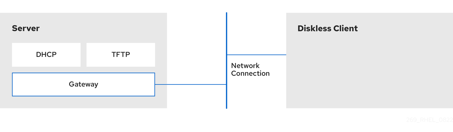
14.1. Preparing environments for the remote diskless system
Prepare your environment to continue with remote diskless system implementation. The remote diskless system booting requires the following services:
- Trivial File Transfer Protocol (TFTP) service, which is provided by tftp-server. The system uses the tftp service to retrieve the kernel image and the initial RAM disk, initrd, over the network, through the Preboot Execution Environment (PXE) loader.
- Dynamic Host Configuration Protocol (DHCP) service, which is provided by dhcp.
Prerequisites
- You have set up your network connection.
Procedure
Install the
dracut-networkpackage:# dnf install dracut-networkAdd the following line to the
/etc/dracut.conf.d/network.conffile:add_dracutmodules+=" nfs "Ensure correct functionality of the remote diskless system in your environment by configuring services in the following order:
- Configure a TFTP service. For more information, see Configuring a TFTP service for diskless clients.
- Configure a DHCP server. For more information, see Configuring a DHCP server for diskless clients.
- Configure the Network File System (NFS) and an exported file system. For more information, see Configuring an exported file system for diskless clients.
14.2. Configuring a TFTP service for diskless clients
For the remote diskless system to function correctly in your environment, you need to first configure a Trivial File Transfer Protocol (TFTP) service for diskless clients.
This configuration does not boot over the Unified Extensible Firmware Interface (UEFI). For UEFI based installation, see Configuring a TFTP server for UEFI-based clients.
Prerequisites
You have installed the following packages:
-
tftp-server -
syslinux
-
Procedure
Enable the
tftpservice:# systemctl enable --now tftpCreate a
pxelinuxdirectory in thetftproot directory:# mkdir -p /var/lib/tftpboot/pxelinux/Copy the
/usr/share/syslinux/pxelinux.0file to the/var/lib/tftpboot/pxelinux/directory:# cp /usr/share/syslinux/pxelinux.0 /var/lib/tftpboot/pxelinux/Copy
/usr/share/syslinux/ldlinux.c32to/var/lib/tftpboot/pxelinux/:# cp /usr/share/syslinux/ldlinux.c32 /var/lib/tftpboot/pxelinux/Create a
pxelinux.cfgdirectory in thetftproot directory:# mkdir -p /var/lib/tftpboot/pxelinux/pxelinux.cfg/
Verification
Check status of service
tftp:# systemctl status tftp ... Active: active (running) ...
14.3. Configuring a DHCP server for diskless clients
The remote diskless system requires several pre-installed services to enable correct functionality.
Prerequisites
- Install the Trivial File Transfer Protocol (TFTP) service.
You have installed the following package:
-
dhcp-server
-
-
You have configured the
tftpservice for diskless clients. For more information, see Configuring a TFTP service for diskless clients.
Procedure
Add the following configuration to the
/etc/dhcp/dhcpd.conffile to setup a DHCP server and enable Preboot Execution Environment (PXE) for booting:option space pxelinux; option pxelinux.magic code 208 = string; option pxelinux.configfile code 209 = text; option pxelinux.pathprefix code 210 = text; option pxelinux.reboottime code 211 = unsigned integer 32; option architecture-type code 93 = unsigned integer 16; subnet 192.168.205.0 netmask 255.255.255.0 { option routers 192.168.205.1; range 192.168.205.10 192.168.205.25; class "pxeclients" { match if substring (option vendor-class-identifier, 0, 9) = "PXEClient"; next-server 192.168.205.1; if option architecture-type = 00:07 { filename "BOOTX64.efi"; } else { filename "pxelinux/pxelinux.0"; } } }Your DHCP configuration might be different depending on your environment, like setting lease time or fixed address. For details, see Providing DHCP services.
NoteWhile using
libvirtvirtual machine as a diskless client, thelibvirtdaemon provides the DHCP service, and the standalone DHCP server is not used. In this situation, network booting must be enabled with thebootp file=<filename>option in thelibvirtnetwork configuration,virsh net-edit.Enable
dhcpd.service:# systemctl enable --now dhcpd.service
Verification
Check the status of service
dhcpd.service:# systemctl status dhcpd.service ... Active: active (running) ...
14.4. Configuring an exported file system for diskless clients
As a part of configuring a remote diskless system in your environment, you must configure an exported file system for diskless clients.
Prerequisites
-
You have configured the
tftpservice for diskless clients. See section Configuring a TFTP service for diskless clients. - You have configured the Dynamic Host Configuration Protocol (DHCP) server. See section Configuring a DHCP server for diskless clients.
Procedure
-
Configure the Network File System (NFS) server to export the root directory by adding it to the
/etc/exportsdirectory. For the complete set of instructions see Deploying an NFS server Install a complete version of Red Hat Enterprise Linux to the root directory to accommodate completely diskless clients. To do that you can either install a new base system or clone an existing installation.
Install Red Hat Enterprise Linux to the exported location by replacing exported-root-directory with the path to the exported file system:
# dnf install @Base kernel dracut-network nfs-utils --installroot=exported-root-directory --releasever=/By setting the
releaseveroption to/, releasever is detected from the host (/) system.Use the
rsyncutility to synchronize with a running system:# rsync -a -e ssh --exclude='/proc/' --exclude='/sys/' example.com:/ exported-root-directory-
Replace example.com with the hostname of the running system with which to synchronize via the
rsyncutility. Replace exported-root-directory with the path to the exported file system.
Note, that for this option you must have a separate existing running system, which you will clone to the server by the command above.
-
Replace example.com with the hostname of the running system with which to synchronize via the
Configure the file system, which is ready for export, before you can use it with diskless clients:
Copy the diskless client supported kernel (
vmlinuz-_kernel-version_pass:attributes) to thetftpboot directory:# cp /exported-root-directory/boot/vmlinuz-kernel-version /var/lib/tftpboot/pxelinux/Create the
initramfs-kernel-version.imgfile locally and move it to the exported root directory with NFS support:# dracut --add nfs initramfs-kernel-version.img kernel-versionFor example:
# dracut --add nfs /exports/root/boot/initramfs-5.14.0-202.el9.x86_64.img 5.14.0-202.el9.x86_64Example for creating initrd, using current running kernel version, and overwriting existing image:
# dracut -f --add nfs "boot/initramfs-$(uname -r).img" "$(uname -r)"Change the file permissions for
initrdto0644:# chmod 0644 /exported-root-directory/boot/initramfs-kernel-version.imgWarningIf you do not change the
initrdfile permissions, thepxelinux.0boot loader fails with a "file not found" error.Copy the resulting
initramfs-kernel-version.imgfile into thetftpboot directory:# cp /exported-root-directory/boot/initramfs-kernel-version.img /var/lib/tftpboot/pxelinux/Add the following configuration in the
/var/lib/tftpboot/pxelinux/pxelinux.cfg/defaultfile to edit the default boot configuration for using theinitrdand the kernel:default rhel9 label rhel9 kernel vmlinuz-kernel-version append initrd=initramfs-kernel-version.img root=nfs:_server-ip_:/exported-root-directory rwThis configuration instructs the diskless client root to mount the
/exported-root-directoryexported file system in a read/write format.Optional: Mount the file system in a
read-only`format by editing the/var/lib/tftpboot/pxelinux/pxelinux.cfg/defaultfile with the following configuration:default rhel9 label rhel9 kernel vmlinuz-kernel-version append initrd=initramfs-kernel-version.img root=nfs:server-ip:/exported-root-directory roRestart the NFS server:
# systemctl restart nfs-server.service
You can now export the NFS share to diskless clients. These clients can boot over the network via Preboot Execution Environment (PXE).
14.5. Re-configuring a remote diskless system
If you want to install packages, restart services, or debug the issues, you can reconfigure the system.
Prerequisites
-
You have enabled the
no_root_squashoption in the exported file system.
Procedure
Change the user password:
Change the command line to /exported/root/directory:
# chroot /exported/root/directory /bin/bashChange the password for the user you want:
# passwd <username>Replace the <username> with a real user for whom you want to change the password.
- Exit the command line.
Install software on a remote diskless system:
# dnf install <package> --installroot=/exported/root/directory --releasever=/ --config /etc/dnf/dnf.conf --setopt=reposdir=/etc/yum.repos.d/Replace <package> with the actual package you want to install.
- Configure two separate exports to split a remote diskless system into a /usr and a /var. For more information, see Deploying an NFS server.
14.6. Troubleshooting common issues with loading a remote diskless system
Based on the earlier configuration, some issues can occur while loading the remote diskless system. Following are some examples of the most common issues and ways to troubleshoot them on a Red Hat Enterprise Linux server.
Example 14.1. The client does not get an IP address
Check if the Dynamic Host Configuration Protocol (DHCP) service is enabled on the server.
Check if the
dhcp.serviceis running:# systemctl status dhcpd.serviceIf the
dhcp.serviceis inactive, enable and start it:# systemctl enable dhcpd.service # systemctl start dhcpd.service- Reboot the diskless client.
-
Check the DHCP configuration file
/etc/dhcp/dhcpd.conf. For details, see Configuring a DHCP server for diskless clients.
Check if the Firewall ports are opened.
Check if the
dhcp.serviceis listed in active services:# firewall-cmd --get-active-zones # firewall-cmd --info-zone=publicIf the
dhcp.serviceis not listed in active services, add it to the list:# firewall-cmd --add-service=dhcp --permanentCheck if the
nfs.serviceis listed in active services:# firewall-cmd --get-active-zones # firewall-cmd --info-zone=publicIf the
nfs.serviceis not listed in active services, add it to the list:# firewall-cmd --add-service=nfs --permanent
Example 14.2. The file is not available during the booting a remote diskless system
-
Check if the file is in the
/var/lib/tftpboot/directory. If the file is in the directory, ensure if it has the following permissions:
# chmod 644 pxelinux.0- Check if the Firewall ports are opened.
Example 14.3. System boot failed after loading kernel/initrd
Check if the NFS service is enabled on a server.
Check if
nfs.serviceis running:# systemctl status nfs.serviceIf the
nfs.serviceis inactive, you must start and enable it:# systemctl start nfs.service # systemctl enable nfs.service
-
Check if the parameters are correct in the
/var/lib/tftpboot/pxelinux.cfg/directory. For details, see Configuring an exported file system for diskless clients. - Check if the Firewall ports are opened.
Chapter 15. Getting started with swap
Use the swap space to provide temporary storage for inactive processes and data, and prevent out-of-memory errors when physical memory is full. The swap space acts as an extension to the physical memory and allows the system to continue running smoothly even when physical memory is exhausted. Note that using swap space can slow down system performance, so optimizing the use of physical memory, before relying on swap space, can be more favorable.
15.1. Overview of swap space
Swap space in Linux is used when the amount of physical memory (RAM) is full. If the system needs more memory resources and the RAM is full, inactive pages in memory are moved to the swap space. While swap space can help machines with a small amount of RAM, it should not be considered a replacement for more RAM.
Swap space is located on hard drives, which have a slower access time than physical memory. Swap space can be a dedicated swap partition (recommended), a swap file, or a combination of swap partitions and swap files.
In years past, the recommended amount of swap space increased linearly with the amount of RAM in the system. However, modern systems often include hundreds of gigabytes of RAM. As a consequence, recommended swap space is considered a function of system memory workload, not system memory.
15.2. Recommended system swap space
The appropriate size of a swap partition ultimately depends on the system memory workload, not system memory alone. However, the following table provides the recommended minimum guidelines for swap partition size based on the amount of RAM in your system, which are typically set automatically during installation.
The swap partition size is set automatically during installation. To allow for hibernation, however, you need to edit the swap space in the custom partitioning stage.
The following guidelines are especially important on systems with low memory, such as 1 GB or less. Failure to allocate sufficient swap space on these systems can cause issues, such as instability or even render the installed system unbootable.
| Amount of RAM in the system | Recommended swap space | Recommended swap space if allowing for hibernation |
|---|---|---|
| Less than 2 GiB | 2 times the amount of RAM | 3 times the amount of RAM |
| 2 GB - 8 GB | Equal to the amount of RAM | 2 times the amount of RAM |
| 8 GB - 64 GB | At least 4 GB | 1.5 times the amount of RAM |
| More than 64 GiB | Workload dependent (at least 4GiB) | Hibernation not recommended |
Distributing swap space over multiple storage devices improves swap space performance, particularly on systems with fast drives, controllers, and interfaces.
File systems and LVM2 volumes assigned as swap space should not be in use when being modified. Any attempts to modify swap fail if a system process or the kernel is using swap space. Use the free and cat /proc/swaps commands to verify how much and where swap is in use.
Resizing swap space requires temporarily removing it from the system, which is done by disabling the swap volume of the file by using the swapoff command. This can be problematic if running applications rely on the additional swap space and might run into low-memory situations.
If you encounter difficulties disabling swap due to high memory pressure or locked pages, alternatively, perform swap resizing from rescue mode. see Debug boot options. When prompted to mount the file system, select .
15.3. Creating an LVM2 logical volume for swap
You can create an LVM2 logical volume for swap. Assuming /dev/VolGroup00/LogVol02 is the swap volume you want to add.
Prerequisites
- You have enough disk space.
Procedure
Create the LVM2 logical volume of size 2 GB:
# lvcreate VolGroup00 -n LogVol02 -L 2GFormat the new swap space:
# mkswap /dev/VolGroup00/LogVol02Add the following entry to the
/etc/fstabfile:/dev/VolGroup00/LogVol02 none swap defaults 0 0Regenerate mount units so that your system registers the new configuration:
# systemctl daemon-reloadActivate swap on the logical volume:
# swapon -v /dev/VolGroup00/LogVol02
Verification
To test if the swap logical volume was successfully created and activated, inspect active swap space by using the following command:
# cat /proc/swaps
               total        used        free      shared  buff/cache   available
Mem:            30Gi       1.2Gi        28Gi        12Mi       994Mi        28Gi
Swap:           22Gi          0B        22Gi
# free -h total used free shared buff/cache available Mem: 30Gi 1.2Gi 28Gi 12Mi 995Mi 28Gi Swap: 17Gi 0B 17Gi
15.4. Creating and managing a standard swap partition
Use a standard swap partition for swap space. You can use standard partitioning tools like fdisk or parted to create a dedicated partition.
Prerequisites
- You have enough unallocated disk space on a drive.
-
You have the name of the disk device, for example,
/dev/sda).
Procedure
Start the partitioning tool for your disk, for example,
/dev/sda:$ fdisk /dev/sdaCreate a new partition of the desired size and set its type to
Linux swap:NoteFor
fdisk, use the 't' command to change the partition type, entering the hex code82for Linux swap.- Write the changes and exit the utility.
Format the new swap partition (assuming the new partition is
/dev/sda4):# mkswap /dev/sda4Add an entry to the
/etc/fstabfile to enable the swap partition at boot time:# /dev/sda4 none swap defaults 0 0Regenerate mount units to register the new configuration:
# systemctl daemon-reloadActivate the swap partition immediately:
# swapon -v /dev/sda4
Verification
To confirm the swap partition was created and activated, inspect the active swap space:
# cat /proc/swaps
# free -h
15.5. Creating a swap file
Set up a swap file to provide virtual memory that prevents system crashes when physical RAM becomes full. This solution is particularly useful when you need additional swap space without repartitioning disks or modifying existing storage configurations.
Prerequisites
- You have enough disk space.
Procedure
- Determine the size of the new swap file in megabytes and multiply by 1024 to determine the number of blocks. For example, the block size of a 64 MB swap file is 65536.
Create an empty file:
# dd if=/dev/zero of=/swapfile bs=1024 count=65536Replace 65536 with the value equal to the required block size.
NoteOn modern filesystems such as ext4 or XFS,
fallocateis preferable instead ofdd. This method is faster and avoids unnecessary disk I/O.Set up the swap file with the command:
# mkswap /swapfileChange the security of the swap file so it is not world readable.
# chmod 0600 /swapfileEdit the
/etc/fstabfile with the following entries to enable the swap file at boot time:/swapfile none swap defaults 0 0The next time the system boots, it activates the new swap file.
Regenerate mount units so that your system registers the new
/etc/fstabconfiguration:# systemctl daemon-reloadActivate the swap file immediately:
# swapon /swapfile
Verification
To test if the new swap file was successfully created and activated, inspect active swap space by using the following command:
$ cat /proc/swaps$ free -h
15.6. Creating a swap volume by using the storage RHEL system role
You can use the storage RHEL system role to create or modify swap volumes on block devices.
Prerequisites
- You have prepared the control node and the managed nodes.
-
The account you use to connect to the managed nodes has
sudopermissions for these nodes.
Procedure
Create a playbook file, for example,
~/playbook.yml, with the following content:--- - name: Create a disk device with swap hosts: managed-node-01.example.com roles: - rhel-system-roles.storage vars: storage_volumes: - name: swap_fs type: disk disks: - /dev/sdb size: 15 GiB fs_type: swapThe volume name (
swap_fsin the example) is currently arbitrary. Thestoragerole identifies the volume by the disk device listed under thedisks:attribute.Validate the playbook syntax:
$ ansible-playbook --syntax-check ~/playbook.ymlNote that this command only validates the syntax and does not protect against a wrong but valid configuration.
Run the playbook:
$ ansible-playbook ~/playbook.yml
15.7. Extending swap on an LVM2 logical volume
You can extend swap space on an existing LVM2 logical volume. Assuming /dev/VolGroup00/LogVol01 is the volume you want to extend by 2 GB.
Prerequisites
- You have enough disk space.
Procedure
Disable swapping for the associated logical volume:
# swapoff -v /dev/VolGroup00/LogVol01Resize the LVM2 logical volume by 2 GB:
# lvresize /dev/VolGroup00/LogVol01 -L +2GFormat the new swap space:
# mkswap /dev/VolGroup00/LogVol01Enable the extended logical volume:
# swapon -v /dev/VolGroup00/LogVol01
Verification
To test if the swap logical volume was successfully extended and activated, inspect active swap space:
# cat /proc/swaps
Filename                Type        Size        Used        Priority
/dev/dm-1          partition    16322556           0              -2
/dev/dm-4          partition     7340028           0              -3
# free -h total used free shared buff/cache available Mem: 30Gi 1.2Gi 28Gi 12Mi 994Mi 28Gi Swap: 22Gi 0B 22Gi
15.8. Reducing swap on an LVM2 logical volume
You can reduce swap on an LVM2 logical volume. Assuming /dev/VolGroup00/LogVol01 is the volume you want to reduce.
Procedure
Disable swapping for the associated logical volume:
# swapoff -v /dev/VolGroup00/LogVol01Clean the swap signature:
# wipefs -a /dev/VolGroup00/LogVol01Reduce the LVM2 logical volume by 512 MB:
# lvreduce /dev/VolGroup00/LogVol01 -L -512MFormat the new swap space:
# mkswap /dev/VolGroup00/LogVol01Activate swap on the logical volume:
# swapon -v /dev/VolGroup00/LogVol01
Verification
To test if the swap logical volume was successfully reduced, inspect active swap space by using the following command:
$ cat /proc/swaps$ free -h
15.9. Removing an LVM2 logical volume for swap
You can remove an LVM2 logical volume for swap. Assuming /dev/VolGroup00/LogVol02 is the swap volume you want to remove.
Procedure
Disable swapping for the associated logical volume:
# swapoff -v /dev/VolGroup00/LogVol02Remove the LVM2 logical volume:
# lvremove /dev/VolGroup00/LogVol02Remove the following associated entry from the
/etc/fstabfile:/dev/VolGroup00/LogVol02 none swap defaults 0 0Regenerate mount units to register the new configuration:
# systemctl daemon-reload
Verification
Test if the logical volume was successfully removed, inspect active swap space by using the following command:
$ cat /proc/swaps$ free -h
15.10. Removing a swap file
You can remove a swap file.
Procedure
Disable the
/swapfileswap file:# swapoff -v /swapfile-
Remove its entry from the
/etc/fstabfile accordingly. Regenerate mount units so that your system registers the new configuration:
# systemctl daemon-reloadRemove the actual file:
# rm /swapfile
15.11. Adjusting Virtual Memory (VM) Tunables
Virtual Memory (VM) tunables are kernel parameters that control how the system manages memory, including how aggressively it uses swap space. Adjusting these settings can significantly impact system performance based on the workload.
The vm.swappiness parameter controls the kernel’s tendency to move processes out of physical memory and into swap space. The value is a percentage, ranging from 0 to 100:
- Higher Value (e.g., 60 or 100): The kernel will swap processes to disk more aggressively. This can free up physical memory for other uses (like the file system cache), but it may increase I/O operations and latency if swapped processes are frequently needed.
- Lower Value (e.g., 0 or 10): The kernel will try to avoid swapping and keep processes in physical memory for as long as possible. This is generally preferred for desktop systems or servers with fast I/O and large amounts of RAM.
Following other relevant VM tunables can influence swap behavior:
- vm.dirty_ratio: The percentage of system memory that can be filled with "dirty" pages (memory pages that have been modified but not yet written to disk) before the kernel begins actively writing them out.
-
vm.dirty_background_ratio: The percentage of system memory that can be filled with dirty pages before a background kernel process begins writing them out. This is a less aggressive action than
vm.dirty_ratio.
Procedure
View the current value:
$ cat /proc/sys/vm/swappinessThe default value is 60.
Set the value temporarily, for example, to 10:
# sysctl vm.swappiness=10Set the value permanently to persist across reboots by editing the
/etc/sysctl.d/99-sysctl.confor a similar configuration file:vm.swappiness = 10Apply the changes:
# sysctl -p
Chapter 16. Configuring Fibre Channel over Ethernet
Based on the IEEE T11 FC-BB-5 standard, Fibre Channel over Ethernet (FCoE) is a protocol to transmit Fibre Channel frames over Ethernet networks. Typically, data centers have a dedicated LAN and Storage Area Network (SAN) that are separated from each other with their own specific configuration. FCoE combines these networks into a single and converged network structure. Benefits of FCoE are, for example, lower hardware and energy costs.
16.1. Using hardware FCoE HBAs in RHEL
In RHEL you can use hardware Fibre Channel over Ethernet (FCoE) Host Bus Adapter (HBA), which is supported by the following drivers:
-
qedf -
bnx2fc -
fnic
If you use such a HBA, you configure the FCoE settings in the setup of the HBA. For more information, see the documentation of the adapter.
After you configure the HBA, the exported Logical Unit Numbers (LUN) from the Storage Area Network (SAN) are automatically available to RHEL as /dev/sd* devices. You can use these devices similar to local storage devices.
16.2. Setting up an FCoE device
After you complete this procedure, the exported LUNs from the Storage Area Network (SAN) are automatically available to RHEL as /dev/sd* devices. You can use these devices in a similar way to local storage devices.
Prerequisites
- You have configured the network switch to support VLAN.
- The SAN uses a VLAN to separate the storage traffic from normal Ethernet traffic.
- You have configured the HBA of the server in its BIOS.
- The HBA is connected to the network and the link is up. For more information, see the documentation of your HBA.
Procedure
Install the
fcoe-utilspackage:# dnf install fcoe-utilsCopy the
/etc/fcoe/cfg-ethxtemplate file to/etc/fcoe/cfg-interface_name. For example, if you want to configure theenp1s0interface to use FCoE, enter the following command:# cp /etc/fcoe/cfg-ethx /etc/fcoe/cfg-enp1s0Enable and start the
fcoeservice:# systemctl enable --now fcoeDiscover the FCoE VLAN on interface
enp1s0, create a network device for the discovered VLAN, and start the initiator:# fipvlan -s -c enp1s0 Created VLAN device enp1s0.200 Starting FCoE on interface enp1s0.200 Fibre Channel Forwarders Discovered interface | VLAN | FCF MAC ------------------------------------------ enp1s0 | 200 | 00:53:00:a7:e7:1bOptional: Display details about the discovered targets, the LUNs, and the devices associated with the LUNs:
# fcoeadm -t
Interface:        enp1s0.200
Roles:            FCP Target
Node Name:        0x500a0980824acd15
Port Name:        0x500a0982824acd15
Target ID:        0
MaxFrameSize:     2048 bytes
OS Device Name:   rport-11:0-1
FC-ID (Port ID):  0xba00a0
State:            Online

LUN ID  Device Name   Capacity   Block Size  Description
------  -----------  ----------  ----------  ---------------------
     0  sdb           28.38 GiB      512     NETAPP LUN (rev 820a)
     ...
This example shows that LUN 0 from the SAN has been attached to the host as the
/dev/sdbdevice.
Verification
Display information about all active FCoE interfaces:
# fcoeadm -i
Description:      BCM57840 NetXtreme II 10 Gigabit Ethernet
Revision:         11
Manufacturer:     Broadcom Inc. and subsidiaries
Serial Number:    000AG703A9B7

Driver:           bnx2x Unknown
Number of Ports:  1

    Symbolic Name:     bnx2fc (QLogic BCM57840) v2.12.13 over enp1s0.200
    OS Device Name:    host11
    Node Name:         0x2000000af70ae935
    Port Name:         0x2001000af70ae935
    Fabric Name:       0x20c8002a6aa7e701
    Speed:             10 Gbit
    Supported Speed:   1 Gbit, 10 Gbit
    MaxFrameSize:      2048 bytes
    FC-ID (Port ID):   0xba02c0
    State:             Online
Chapter 17. Managing tape devices
A tape device is a magnetic tape where data is stored and accessed sequentially. Data is written to this tape device with the help of a tape drive. There is no need to create a file system in order to store data on a tape device. Tape drives can be connected to a host computer with various interfaces like, SCSI, FC, USB, SATA, and other interfaces.
17.1. Types of tape devices
The following is a list of the different types of tape devices:
-
/dev/st0is a rewinding tape device. -
/dev/nst0is a non-rewinding tape device. Use non-rewinding devices for daily backups.
There are several advantages to using tape devices. They are cost efficient and stable. Tape devices are also resilient against data corruption and are suitable for data retention.
17.2. Installing tape drive management tool
Install the mt-st package for tape drive operations. Use the mt utility to control magnetic tape drive operations, and the st utility for SCSI tape driver.
Procedure
Install the
mt-stpackage:# dnf install mt-st
17.3. Tape commands
The following are the common mt commands:
| Command | Description |
|---|---|
|
| Displays the status of the tape device. |
|
| Erases the entire tape. |
|
| Rewinds the tape device. |
|
| Switches the tape head to the forward record. Here, n is an optional file count. If a file count is specified, tape head skips n records. |
|
| Switches the tape head to the previous record. |
|
| Switches the tape head to the end of the data. |
17.4. Writing to rewinding tape devices
A rewind tape device rewinds the tape after every operation. To back up data, you can use the tar command. By default, in tape devices the block size is 10KB (bs=10k). You can set the TAPE environment variable using the export TAPE=/dev/st0 attribute. Use the -f device option instead, to specify the tape device file. This option is useful when you use more than one tape device.
Prerequisites
-
You have installed the
mt-stpackage. For more information, see Installing tape drive management tool. Load the tape drive:
# mt -f /dev/st0 load
Procedure
Check the tape head:
# mt -f /dev/st0 status

SCSI 2 tape drive:
File number=-1, block number=-1, partition=0.
Tape block size 0 bytes. Density code 0x0 (default).
Soft error count since last status=0
General status bits on (50000):
 DR_OPEN IM_REP_EN
Here:
-
the current
file numberis -1. -
the
block numberdefines the tape head. By default, it is set to -1. -
the
block size0 indicates that the tape device does not have a fixed block size. -
the
Soft error countindicates the number of encountered errors after executing the mt status command. -
the
General status bitsexplains the stats of the tape device. -
DR_OPENindicates that the door is open and the tape device is empty.IM_REP_ENis the immediate report mode.
-
the current
If the tape device is not empty, overwrite it:
# tar -czf /dev/st0 _/source/directoryThis command overwrites the data on a tape device with the content of
/source/directory.Back up the
/source/directoryto the tape device:# tar -czf /dev/st0 _/source/directory tar: Removing leading `/' from member names /source/directory /source/directory/man_db.conf /source/directory/DIR_COLORS /source/directory/rsyslog.conf [...]View the status of the tape device:
# mt -f /dev/st0 status
Verification
View the list of all files on the tape device:
# tar -tzf /dev/st0
/source/directory/
/source/directory/man_db.conf
/source/directory/DIR_COLORS
/source/directory/rsyslog.conf
[...]
17.5. Writing to non-rewinding tape devices
A non-rewinding tape device leaves the tape in its current status, after completing the execution of a certain command. For example, after a backup, you could append more data to a non-rewinding tape device. You can also use it to avoid any unexpected rewinds.
Prerequisites
-
You have installed the
mt-stpackage. For more information, see Installing tape drive management tool. Load the tape drive:
# mt -f /dev/nst0 load
Procedure
Check the tape head of the non-rewinding tape device
/dev/nst0:# mt -f /dev/nst0 statusSpecify the pointer at the head or at the end of the tape:
# mt -f /dev/nst0 rewindAppend the data on the tape device:
# mt -f /dev/nst0 eod
# tar -czf /dev/nst0 /source/directory/
Back up the
/source/directory/to the tape device:# tar -czf /dev/nst0 /source/directory/ tar: Removing leading `/' from member names /source/directory/ /source/directory/man_db.conf /source/directory/DIR_COLORS /source/directory/rsyslog.conf [...]View the status of the tape device:
# mt -f /dev/nst0 status
Verification
View the list of all files on the tape device:
# tar -tzf /dev/nst0
/source/directory/
/source/directory/man_db.conf
/source/directory/DIR_COLORS
/source/directory/rsyslog.conf
[...]
17.6. Switching tape head in tape devices
You can switch the tape head in the tape device by using the eod option.
Prerequisites
-
You have installed the
mt-stpackage. For more information, see Installing tape drive management tool. - Data is written to the tape device. Fore more information, see Writing to rewinding tape devices or Writing to non-rewinding tape devices.
Procedure
To view the current position of the tape pointer:
# mt -f /dev/nst0 tellTo switch the tape head, while appending the data to the tape devices:
# mt -f /dev/nst0 eodTo go to the previous record:
# mt -f /dev/nst0 bsfm 1To go to the forward record:
# mt -f /dev/nst0 fsf 1
17.7. Restoring data from tape devices
You can restore data from a tape device by using the tar command.
Prerequisites
-
You have installed the
mt-stpackage. For more information, see Installing tape drive management tool. - Data is written to the tape device. For more information, see Writing to rewinding tape devices or Writing to non-rewinding tape devices.
Procedure
For rewinding tape devices
/dev/st0:Restore the
/source/directory/:# tar -xzf /dev/st0 /source/directory/
For non-rewinding tape devices
/dev/nst0:Rewind the tape device:
# mt -f /dev/nst0 rewindRestore the
etcdirectory:# tar -xzf /dev/nst0 /source/directory/
17.8. Erasing data from tape devices
You can erase data from a tape device by using the erase option.
Prerequisites
-
You have installed the
mt-stpackage. For more information, see Installing tape drive management tool. - Data is written to the tape device. For more information, see Writing to rewinding tape devices or Writing to non-rewinding tape devices.
Procedure
Erase data from the tape device:
# mt -f /dev/st0 eraseUnload the tape device:
# mt -f /dev/st0 offline
Chapter 18. Managing RAID
You can use a Redundant Array of Independent Disks (RAID) to store data across multiple drives. It can help to avoid data loss if a drive has failed.
18.1. Overview of RAID
In a RAID, multiple devices, such as HDD, SSD, or NVMe are combined into an array to accomplish performance or redundancy goals not achievable with one large and expensive drive. This array of devices appears to the computer as a single logical storage unit or drive.
RAID supports various configurations, including levels 0, 1, 4, 5, 6, 10, and linear. RAID uses techniques such as disk striping (RAID Level 0), disk mirroring (RAID Level 1), and disk striping with parity (RAID Levels 4, 5 and 6) to achieve redundancy, lower latency, increased bandwidth, and maximized ability to recover from hard disk crashes.
RAID distributes data across each device in the array by breaking it down into consistently-sized chunks, commonly 256 KB or 512 KB, although other values are acceptable. It writes these chunks to a hard drive in the RAID array according to the RAID level employed. While reading the data, the process is reversed, giving the illusion that the multiple devices in the array are actually one large drive.
RAID technology is beneficial for those who manage large amounts of data. The following are the primary reasons to deploy RAID:
- It enhances speed
- It increases storage capacity using a single virtual disk
- It minimizes data loss from disk failure
- The RAID layout and level online conversion
18.2. RAID types
The following are the possible types of RAID:
- Firmware RAID
- Firmware RAID, also known as ATARAID, is a type of software RAID where the RAID sets can be configured using a firmware-based menu. The firmware used by this type of RAID also hooks into the BIOS, allowing you to boot from its RAID sets. Different vendors use different on-disk metadata formats to mark the RAID set members. The Intel Matrix RAID is an example of a firmware RAID system.
- Hardware RAID
A hardware-based array manages the RAID subsystem independently from the host. It might present multiple devices per RAID array to the host.
Hardware RAID devices might be internal or external to the system. Internal devices commonly consists of a specialized controller card that handles the RAID tasks transparently to the operating system. External devices commonly connect to the system via SCSI, Fibre Channel, iSCSI, InfiniBand, or other high speed network interconnect and present volumes such as logical units to the system.
RAID controller cards function like a SCSI controller to the operating system and handle all the actual drive communications. You can plug the drives into the RAID controller similar to a normal SCSI controller and then add them to the RAID controller’s configuration. The operating system will not be able to tell the difference.
- Software RAID
A software RAID implements the various RAID levels in the kernel block device code. It offers the cheapest possible solution because expensive disk controller cards or hot-swap chassis are not required. With hot-swap chassis, you can remove a hard drive without powering off your system. Software RAID also works with any block storage, which are supported by the Linux kernel, such as SATA, SCSI, and NVMe. With today’s faster CPUs, Software RAID also generally outperforms hardware RAID, unless you use high-end storage devices.
Since the Linux kernel contains a multiple device (MD) driver, the RAID solution becomes completely hardware independent. The performance of a software-based array depends on the server CPU performance and load.
The following are the key features of the Linux software RAID stack:
- Multithreaded design
- Portability of arrays between Linux machines without reconstruction
- Backgrounded array reconstruction using idle system resources
- Hot-swap drive support
- Automatic CPU detection to take advantage of certain CPU features such as streaming Single Instruction Multiple Data (SIMD) support.
- Automatic correction of bad sectors on disks in an array.
- Regular consistency checks of RAID data to ensure the health of the array.
- Proactive monitoring of arrays with email alerts sent to a designated email address on important events.
Write-intent bitmaps, which drastically increase the speed of resync events by allowing the kernel to know precisely which portions of a disk need to be resynced instead of having to resync the entire array after a system crash.
NoteThe resync is a process to synchronize the data over the devices in the existing RAID to achieve redundancy.
- Resync checkpointing so that if you reboot your computer during a resync, at startup the resync resumes where it left off and not starts all over again.
- The ability to change parameters of the array after installation, which is called reshaping. For example, you can grow a 4-disk RAID5 array to a 5-disk RAID5 array when you have a new device to add. This grow operation is done live and does not require you to reinstall on the new array.
- Reshaping supports changing the number of devices, the RAID algorithm or size of the RAID array type, such as RAID4, RAID5, RAID6, or RAID10.
- Takeover supports RAID level conversion, such as RAID0 to RAID6.
- Cluster MD, which is a storage solution for a cluster, provides the redundancy of RAID1 mirroring to the cluster. Currently, only RAID1 is supported.
18.3. RAID levels and linear support
The following are the supported configurations by RAID, including levels 0, 1, 4, 5, 6, 10, and linear:
- Level 0
RAID level 0, often called striping, is a performance-oriented striped data mapping technique. This means the data being written to the array is broken down into stripes and written across the member disks of the array, allowing high I/O performance at low inherent cost but provides no redundancy.
RAID level 0 implementations only stripe the data across the member devices up to the size of the smallest device in the array. This means that if you have multiple devices with slightly different sizes, each device gets treated as though it was the same size as the smallest drive. Therefore, the common storage capacity of a level 0 array is the total capacity of all disks. If the member disks have a different size, then the RAID0 uses all the space of those disks using the available zones.
- Level 1
RAID level 1, or mirroring, provides redundancy by writing identical data to each member disk of the array, leaving a mirrored copy on each disk. Mirroring remains popular due to its simplicity and high level of data availability. Level 1 operates with two or more disks, and provides very good data reliability and improves performance for read-intensive applications but at relatively high costs.
RAID level 1 is costly because you write the same information to all of the disks in the array, which provides data reliability, but in a much less space-efficient manner than parity based RAID levels such as level 5. However, this space inefficiency comes with a performance benefit, which is parity-based RAID levels that consume considerably more CPU power in order to generate the parity while RAID level 1 simply writes the same data more than once to the multiple RAID members with very little CPU overhead. As such, RAID level 1 can outperform the parity-based RAID levels on machines where software RAID is employed and CPU resources on the machine are consistently taxed with operations other than RAID activities.
The storage capacity of the level 1 array is equal to the capacity of the smallest mirrored hard disk in a hardware RAID or the smallest mirrored partition in a software RAID. Level 1 redundancy is the highest possible among all RAID types, with the array being able to operate with only a single disk present.
- Level 4
Level 4 uses parity concentrated on a single disk drive to protect data. Parity information is calculated based on the content of the rest of the member disks in the array. This information can then be used to reconstruct data when one disk in the array fails. The reconstructed data can then be used to satisfy I/O requests to the failed disk before it is replaced and to repopulate the failed disk after it has been replaced.
Since the dedicated parity disk represents an inherent bottleneck on all write transactions to the RAID array, level 4 is seldom used without accompanying technologies such as write-back caching. Or it is used in specific circumstances where the system administrator is intentionally designing the software RAID device with this bottleneck in mind such as an array that has little to no write transactions once the array is populated with data. RAID level 4 is so rarely used that it is not available as an option in Anaconda. However, it could be created manually by the user if needed.
The storage capacity of hardware RAID level 4 is equal to the capacity of the smallest member partition multiplied by the number of partitions minus one. The performance of a RAID level 4 array is always asymmetrical, which means reads outperform writes. This is because write operations consume extra CPU resources and main memory bandwidth when generating parity, and then also consume extra bus bandwidth when writing the actual data to disks because you are not only writing the data, but also the parity. Read operations need only read the data and not the parity unless the array is in a degraded state. As a result, read operations generate less traffic to the drives and across the buses of the computer for the same amount of data transfer under normal operating conditions.
- Level 5
This is the most common type of RAID. By distributing parity across all the member disk drives of an array, RAID level 5 eliminates the write bottleneck inherent in level 4. The only performance bottleneck is the parity calculation process itself. Modern CPUs can calculate parity very fast. However, if you have a large number of disks in a RAID 5 array such that the combined aggregate data transfer speed across all devices is high enough, parity calculation can be a bottleneck.
Level 5 has asymmetrical performance, and reads substantially outperforming writes. The storage capacity of RAID level 5 is calculated the same way as with level 4.
- Level 6
This is a common level of RAID when data redundancy and preservation, and not performance, are the paramount concerns, but where the space inefficiency of level 1 is not acceptable. Level 6 uses a complex parity scheme to be able to recover from the loss of any two drives in the array. This complex parity scheme creates a significantly higher CPU burden on software RAID devices and also imposes an increased burden during write transactions. As such, level 6 is considerably more asymmetrical in performance than levels 4 and 5.
The total capacity of a RAID level 6 array is calculated similarly to RAID level 5 and 4, except that you must subtract two devices instead of one from the device count for the extra parity storage space.
- Level 10
This RAID level attempts to combine the performance advantages of level 0 with the redundancy of level 1. It also reduces some of the space wasted in level 1 arrays with more than two devices. With level 10, it is possible, for example, to create a 3-drive array configured to store only two copies of each piece of data, which then allows the overall array size to be 1.5 times the size of the smallest devices instead of only equal to the smallest device, similar to a 3-device, level 1 array. This avoids CPU process usage to calculate parity similar to RAID level 6, but it is less space efficient.
The creation of RAID level 10 is not supported during installation. It is possible to create one manually after installation.
- Linear RAID
Linear RAID is a grouping of drives to create a larger virtual drive.
In linear RAID, the chunks are allocated sequentially from one member drive, going to the next drive only when the first is completely filled. This grouping provides no performance benefit, as it is unlikely that any I/O operations split between member drives. Linear RAID also offers no redundancy and decreases reliability. If any one member drive fails, the entire array cannot be used and data can be lost. The capacity is the total of all member disks.
18.4. Supported RAID conversions
It is possible to convert from one RAID level to another. For example, you can convert from RAID5 to RAID10, but not from RAID10 to RAID5. The following table describes the supported RAID conversions:
| RAID conversion levels | Conversion steps | Notes |
|---|---|---|
| RAID level 0 to RAID level 4 |
| You need to add a disk to the MD array because it require at least 3 disks. |
| RAID level 0 to RAID level 5 |
| You need to add a disk to the MD array because it require at least 3 disks. |
| RAID level 0 to RAID level 10 |
| You need to add two extra disks to the MD array. |
| RAID level 1 to RAID level 0 |
| |
| RAID level 1 to RAID level 5 |
| |
| RAID level 4 to RAID level 0 |
| |
| RAID level 4 to RAID level 5 |
| |
| RAID level 5 to RAID level 0 |
| |
| RAID level 5 to RAID level 1 |
| |
| RAID level 5 to RAID level 4 |
| |
| RAID level 5 to RAID level 6 |
| |
| RAID level 5 to RAID level 10 |
| Converting RAID level 5 to RAID level 10 is a two step conversion:
|
| RAID level 6 to RAID level 5 |
| |
| RAID level 10 to RAID level 0 |
|
Converting RAID 5 to RAID0 and RAID4 is only possible with the ALGORITHM_PARITY_N layout.
After converting a RAID level, verify the conversion by using either the mdadm --detail /dev/md0 or cat /proc/mdstat command.
18.5. RAID subsystems
The following subsystems compose RAID:
- Hardware RAID Controller Drivers
- Hardware RAID controllers have no specific RAID subsystem. Since they use special RAID chipsets, hardware RAID controllers come with their own drivers. With these drivers, the system detects the RAID sets as regular disks.
mdraidThe
mdraidsubsystem was designed as a software RAID solution. It is also the preferred solution for software RAID in Red Hat Enterprise Linux. This subsystem uses its own metadata format, which is referred to as native MD metadata.It also supports other metadata formats, known as external metadata. Red Hat Enterprise Linux 9 uses
mdraidwith external metadata to access Intel Rapid Storage (ISW) or Intel Matrix Storage Manager (IMSM) sets and Storage Networking Industry Association (SNIA) Disk Drive Format (DDF). Themdraidsubsystem sets are configured and controlled through themdadmutility.
18.6. Creating a software RAID during the installation
Redundant Arrays of Independent Disks (RAID) devices are constructed from multiple storage devices that are arranged to provide increased performance and, in some configurations, greater fault tolerance. A RAID device is created in one step and disks are added or removed as necessary. You can configure one RAID partition for each physical disk in your system, so that the number of disks available to the installation program determines the levels of RAID device available. For example, if your system has two disks, you cannot create a RAID 10 device, as it requires a minimum of three separate disks. To optimize your system’s storage performance and reliability, RHEL supports software RAID 0, RAID 1, RAID 4, RAID 5, RAID 6, and RAID 10 types with LVM and LVM Thin Provisioning to set up storage on the installed system.
On 64-bit IBM Z, the storage subsystem uses RAID transparently. You do not have to configure software RAID manually.
Prerequisites
- You have selected two or more disks for installation before RAID configuration options are visible. Depending on the RAID type you want to create, at least two disks are required.
- You have created a mount point. By configuring a mount point, you can configure the RAID device.
- You have selected the radio button on the Installation Destination window.
Procedure
- From the left pane of the Manual Partitioning window, select the required partition.
- Under the Device(s) section, click . The Configure Mount Point dialog box opens.
- Select the disks that you want to include in the RAID device and click .
- Click the Device Type drop-down menu and select RAID.
- Click the File System drop-down menu and select your preferred file system type.
- Click the RAID Level drop-down menu and select your preferred level of RAID.
- Click to save your changes.
- Click to apply the settings to return to the Installation Summary window.
18.7. Creating a software RAID on an installed system
You can create a software Redundant Array of Independent Disks (RAID) on an existing system using the mdadm utility.
Prerequisites
-
The
mdadmpackage is installed. - You have created two or more partitions on your system. For detailed instructions, see Creating a partition with parted.
Procedure
Create a RAID of two block devices, for example /dev/sda1 and /dev/sdc1:
# mdadm --create /dev/md0 --level=0 --raid-devices=2 /dev/sda1 /dev/sdc1
mdadm: Defaulting to version 1.2 metadata
mdadm: array /dev/md0 started.
The level_value option defines the RAID level.
Optional: Check the status of the RAID:
# mdadm --detail /dev/md0
/dev/md0:
           Version : 1.2
     Creation Time : Thu Oct 13 15:17:39 2022
        Raid Level : raid0
        Array Size : 18649600 (17.79 GiB 19.10 GB)
      Raid Devices : 2
     Total Devices : 2
       Persistence : Superblock is persistent

       Update Time : Thu Oct 13 15:17:39 2022
             State : clean
    Active Devices : 2
   Working Devices : 2
    Failed Devices : 0
     Spare Devices : 0
[...]
Optional: Observe the detailed information about each device in the RAID:
# mdadm --examine /dev/sda1 /dev/sdc1
/dev/sda1:
          Magic : a92b4efc
        Version : 1.2
    Feature Map : 0x1000
     Array UUID : 77ddfb0a:41529b0e:f2c5cde1:1d72ce2c
           Name : 0
  Creation Time : Thu Oct 13 15:17:39 2022
     Raid Level : raid0
   Raid Devices : 2
[...]
Create a file system on the RAID drive:
# mkfs -t xfs /dev/md0Replace xfs with the file system that you chose to format the drive with.
Create a mount point for RAID drive and mount it:
# mkdir /mnt/raid1
# mount /dev/md0 /mnt/raid1
Replace /mnt/raid1 with the mount point.
If you want that RHEL mounts the
md0RAID device automatically when the system boots, add an entry for your device to the/etc/fstab file:/dev/md0 /mnt/raid1 xfs defaults 0 0
18.8. Creating RAID in the web console
Configure RAID in the RHEL 9 web console.
Prerequisites
- You have installed the RHEL 9 web console.
- You have enabled the cockpit service.
Your user account is allowed to log in to the web console.
For instructions, see Installing and enabling the web console.
-
You have installed the
cockpit-storagedpackage on your system. - You have connected physical disks and they are visible by the system.
Procedure
Log in to the RHEL 9 web console.
For details, see Logging in to the web console.
- In the panel, click Storage.
- In the Storage table, click the menu button and select Create MDRAID device.
- In the Create RAID Device field, enter a name for the new RAID.
- In the RAID Level drop-down list, select a level of RAID you want to use.
From the Chunk Size drop-down list, select the size from the list of available options.
The Chunk Size value specifies how large each block is for data writing. For example, if the chunk size is 512 KiB, the system writes the first 512 KiB to the first disk, the second 512 KiB is written to the second disk, and the third chunk is written to the third disk. If you have three disks in your RAID, the fourth 512 KiB is written to the first disk again.
- Select the disks you want to use for RAID.
- Click Create.
Verification
- Go to the Storage section and check that you can see the new RAID in the RAID devices box.
18.9. Formatting RAID in the web console
You can format and mount software RAID devices in the RHEL 9 web console.
Formatting can take several minutes depending on the volume size and which formatting options are selected.
Prerequisites
- You have installed the RHEL 9 web console.
- You have enabled the cockpit service.
Your user account is allowed to log in to the web console.
For instructions, see Installing and enabling the web console.
-
You have installed the
cockpit-storagedpackage. - You have connected physical disks and they are visible by the system.
- You have created RAID.
Procedure
Log in to the RHEL 9 web console.
For details, see Logging in to the web console.
- In the panel, click Storage.
- In the Storage table, click the menu button for the RAID device that you want to format.
- From the drop-down menu, select .
- In the Format field, enter a name.
- In the Mount Point field, add the mount path.
- From the Type drop-down list, select the type of file system.
- Optional: Check the Overwrite existing data with zeros option, if the disk includes any sensitive data and you want to overwrite them. Otherwise the RHEL web console rewrites only the disk header.
- In the Encryption drop-down menu, select the type of encryption. If you do not want to encrypt the volume, select No encryption.
- In the At boot drop-down menu, select when you want to mount the volume.
In the Mount options section:
- If you want the to mount the volume as a read-only logical volume, select the Mount read only checkbox.
- If you want to change the default mount option, select the Custom mount options checkbox and add the mount options.
Format the RAID partition:
- If you want to format and mount the partition, click the button.
- If you want to only format the partition, click the button.
Verification
- After the formatting has completed successfully, you can see the details of the formatted logical volume in the Storage table on the Storage page.
18.10. Creating a partition table on RAID by using the web console
Format RAID with the partition table on the new software RAID device created in the RHEL 9 interface.
Prerequisites
- You have installed the RHEL 9 web console.
- You have enabled the cockpit service.
Your user account is allowed to log in to the web console.
For instructions, see Installing and enabling the web console.
-
You have installed the
cockpit-storagedpackage. - You have connected physical disks and they are visible by the system.
- You have created RAID.
Procedure
Log in to the RHEL 9 web console.
For details, see Logging in to the web console.
- In the panel, click Storage.
- In the Storage table, click the RAID device on which you want to create a partition table.
- Click the menu button in the MDRAID device section.
- From the drop-down menu, select .
In the Initialize disk dialog box, select the following:
Partitioning:
- If the partition should be compatible with all systems and devices, select MBR.
- If the partition should be compatible with modern system and hard disks must be greater than 2 TB, select GPT.
- If you do not need partitioning, select No partitioning.
Overwrite:
- Check the Overwrite existing data with zeros option if the disk includes any sensitive data and you want to overwrite them. Otherwise the RHEL web console rewrites only the disk header.
- Click .
18.11. Creating partitions on RAID by using the web console
Create a partition in the existing partition table. You can create more partitions after the partition is created.
Prerequisites
- The RHEL 9 web console is installed and accessible. For details, see Installing the web console.
-
The
cockpit-storagedpackage is installed on your system. - A partition table on RAID is created.
Procedure
Log in to the RHEL 9 web console.
For details, see Logging in to the web console.
- In the panel, click Storage.
- Click the RAID device on which you want to create a partition.
- On the RAID device page, scroll to the GPT partitions section and click the menu button [⋮].
- Click and enter a name for the file system in the Create partition field. Do not use spaces in the name.
- In the Mount Point field, enter the mount path.
- In the Type drop-down list, select the type of file system.
- In the Size slider, set the size of the partition.
- Optional: Select Overwrite existing data with zeros, if the disk includes any sensitive data and you want to overwrite them. Otherwise the RHEL web console rewrites only the disk header.
- In the Encryption drop-down menu, select the type of encryption. If you do not want to encrypt the volume, select No encryption.
- In the At boot drop-down menu, select when you want to mount the volume.
In the Mount options section:
- If you want to mount the volume as a read-only logical volume, select the Mount read only checkbox.
- If you want to change the default mount option, select the Custom mount options checkbox and add the mount options.
Create the partition:
- If you want to create and mount the partition, click the button.
If you want to only create the partition, click the button.
Formatting can take several minutes depending on the volume size and which formatting options are selected.
Verification
- You can see the details of the formatted logical volume in the Storage table on the main storage page.
18.12. Creating a volume group on top of RAID by using the web console
Build a volume group from software RAID.
Prerequisites
- You have installed the RHEL 9 web console.
- You have enabled the cockpit service.
Your user account is allowed to log in to the web console.
For instructions, see Installing and enabling the web console.
-
You have installed the
cockpit-storagedpackage. - You have a RAID device that is not formatted and not mounted.
Procedure
Log in to the RHEL 9 web console.
For details, see Logging in to the web console.
- In the panel, click Storage.
- In the Storage table, click the menu button [⋮] and select Create LVM2 volume group.
- In the Create LVM2 volume group field, enter a name for the new volume group.
From the Disks list, select a RAID device.
If you do not see the RAID in the list, unmount the RAID from the system. The RAID device must not be in use by the RHEL 9 system.
- Click .
18.13. Configuring a RAID volume by using the storage RHEL system role
With the storage system role, you can configure a RAID volume on RHEL by using Red Hat Ansible Automation Platform and Ansible-Core. Create an Ansible playbook with the parameters to configure a RAID volume to suit your requirements.
Device names might change in certain circumstances, for example, when you add a new disk to a system. Therefore, to prevent data loss, use persistent naming attributes in the playbook. For more information about persistent naming attributes, see Persistent naming attributes.
Prerequisites
- You have prepared the control node and the managed nodes.
-
The account you use to connect to the managed nodes has
sudopermissions for these nodes.
Procedure
Create a playbook file, for example,
~/playbook.yml, with the following content:--- - name: Manage local storage hosts: managed-node-01.example.com tasks: - name: Create a RAID on sdd, sde, sdf, and sdg ansible.builtin.include_role: name: redhat.rhel_system_roles.storage vars: storage_safe_mode: false storage_volumes: - name: data type: raid disks: [sdd, sde, sdf, sdg] raid_level: raid0 raid_chunk_size: 32 KiB mount_point: /mnt/data state: presentFor details about all variables used in the playbook, see the
/usr/share/ansible/roles/rhel-system-roles.storage/README.mdfile on the control node.Validate the playbook syntax:
$ ansible-playbook --syntax-check ~/playbook.ymlNote that this command only validates the syntax and does not protect against a wrong but valid configuration.
Run the playbook:
$ ansible-playbook ~/playbook.yml
Verification
Verify that the array was correctly created:
# ansible managed-node-01.example.com -m command -a 'mdadm --detail /dev/md/data'
18.15. Shrinking RAID
You can shrink RAID using the --grow option of the mdadm utility.
The XFS file system does not support shrinking.
Prerequisites
-
The
partedpackage is installed.
Procedure
- Shrink the file system. For more information, see Managing file systems.
Decrease the RAID to the size, for example to 512 MB:
# mdadm --grow --size=524228 /dev/md0Write the
--sizeparameter in kB.- Shrink the partition to the size you need.
18.16. Converting a root disk to RAID1 after installation
You can convert a non-RAID root disk to a RAID1 mirror after installing Red Hat Enterprise Linux 9.
Procedure
- On the x86 architecture complete the steps in the Red Hat Knowledgebase solution How to convert single disk EFI boot to software RAID after installation of Red Hat Enterprise Linux 9.
- On the PowerPC (PPC) architecture complete the steps in the Red Hat Knowledgebase solution How do I convert my root disk to RAID1 after installation of Red Hat Enterprise Linux 9.
18.17. Creating advanced RAID devices
In some cases, you might want to install the operating system on an array that is created before the installation completes. Usually, this means setting up the /boot or root file system arrays on a complex RAID device. In such cases, you might need to use array options that are not supported by the Anaconda installer. To work around this, perform the following steps.
The limited Rescue Mode of the installer does not include man pages. Both the mdadm and md man pages contain useful information for creating custom RAID arrays, and might be needed throughout the workaround.
Procedure
- Insert the install disk.
-
During the initial boot up, select Rescue Mode instead of Install or Upgrade. When the system fully boots into
Rescue mode, you can see the command line terminal. From this terminal, execute the following commands:
-
Create RAID partitions on the target hard drives by using the
partedcommand. -
Manually create raid arrays by using the
mdadmcommand from those partitions using any and all settings and options available.
-
Create RAID partitions on the target hard drives by using the
- Optional: After creating arrays, create file systems on the arrays as well.
- Reboot the computer and select Install or Upgrade to install. As the Anaconda installer searches the disks in the system, it finds the pre-existing RAID devices.
- When asked about how to use the disks in the system, select Custom Layout and click . In the device listing, the pre-existing MD RAID devices are listed.
- Select a RAID device and click .
- Configure its mount point and optionally the type of file system it should use if you did not create one earlier, and then click . Anaconda installs to this pre-existing RAID device, preserving the custom options you selected when you created it in Rescue Mode.
18.18. Setting up email notifications to monitor a RAID
You can set up email alerts to monitor RAID with the mdadm tool. Once the MAILADDR variable is set to the required email address, the monitoring system sends the alerts to the added email address.
Prerequisites
-
The
mdadmpackage is installed. - The mail service is set up.
Procedure
Create the
/etc/mdadm.confconfiguration file for monitoring array by scanning the RAID details:# mdadm --detail --scan >> /etc/mdadm.confNote, that
ARRAYandMAILADDRare mandatory variables.Open the
/etc/mdadm.confconfiguration file with a text editor of your choice and add theMAILADDRvariable with the mail address for the notification. For example, add new line:MAILADDR example@example.comHere, example@example.com is an email address to which you want to receive the alerts from the array monitoring.
-
Save changes in the
/etc/mdadm.conffile and close it.
18.19. Replacing a failed disk in RAID
You can reconstruct the data from the failed disks using the remaining disks. RAID level and the total number of disks determines the minimum amount of remaining disks needed for a successful data reconstruction.
In this procedure, the /dev/md0 RAID contains four disks. The /dev/sdd disk has failed and you need to replace it with the /dev/sdf disk.
Prerequisites
- A spare disk for replacement.
-
The
mdadmpackage is installed.
Procedure
Check the failed disk:
View the kernel logs:
# journalctl -k -fSearch for a message similar to the following:
md/raid:md0: Disk failure on sdd, disabling device. md/raid:md0: Operation continuing on 3 devices.-
Press Ctrl+C on your keyboard to exit the
journalctlprogram.
Mark the failed disk as faulty:
# mdadm --manage /dev/md0 --fail /dev/sddOptional: Check if the failed disk was marked correctly:
# mdadm --detail /dev/md0At the end of the output is a list of disks in the /dev/md0 RAID where the disk /dev/sdd has the faulty status:
Number   Major   Minor   RaidDevice State
   0       8       16        0      active sync   /dev/sdb
   1       8       32        1      active sync   /dev/sdc
   -       0        0        2      removed
   3       8       64        3      active sync   /dev/sde

   2       8       48        -      faulty   /dev/sdd
Remove the failed disk from the RAID:
# mdadm --manage /dev/md0 --remove /dev/sddWarningIf your RAID cannot withstand another disk failure, do not remove any disk until the new disk has the active sync status. You can monitor the progress using the
watch cat /proc/mdstatcommand.Add the new disk to the RAID:
# mdadm --manage /dev/md0 --add /dev/sdfThe /dev/md0 RAID now includes the new disk /dev/sdf and the
mdadmservice will automatically starts copying data to it from other disks.
Verification
Check the details of the array:
# mdadm --detail /dev/md0If this command shows a list of disks in the /dev/md0 RAID where the new disk has spare rebuilding status at the end of the output, data is still being copied to it from other disks:
Number   Major   Minor   RaidDevice State
   0       8       16        0      active sync   /dev/sdb
   1       8       32        1      active sync   /dev/sdc
   4       8       80        2      spare rebuilding   /dev/sdf
   3       8       64        3      active sync   /dev/sde
After data copying is finished, the new disk has an active sync status.
18.20. Repairing RAID disks
You can repair disks in a RAID array by using the repair option.
Prerequisites
-
The
mdadmpackage is installed.
Procedure
Check the array for the failed disks behavior:
# echo check > /sys/block/md0/md/sync_actionThis checks the array and the
/sys/block/md0/md/sync_actionfile shows the sync action.-
Open the
/sys/block/md0/md/sync_actionfile with the text editor of your choice and see if there is any message about disk synchronization failures. -
View the
/sys/block/md0/md/mismatch_cntfile. If themismatch_cntparameter is not0, it means that the RAID disks need repair. Repair the disks in the array:
# echo repair > /sys/block/md0/md/sync_actionThis repairs the disks in the array and writes the result into the
/sys/block/md0/md/sync_actionfile.View the synchronization progress:
# cat /sys/block/md0/md/sync_action
repair

# cat /proc/mdstat
Personalities : [raid0] [raid6] [raid5] [raid4] [raid1]
md0 : active raid1 sdg[1] dm-3[0]
      511040 blocks super 1.2 [2/2] [UU]
unused devices: <none>
Chapter 19. Encrypting block devices using LUKS
By using the disk encryption, you can protect the data on a block device by encrypting it. To access the device’s decrypted contents, enter a passphrase or key as authentication. This is important for mobile computers and removable media because it helps to protect the device’s contents even if it has been physically removed from the system. The LUKS format is a default implementation of block device encryption in Red Hat Enterprise Linux.
19.1. LUKS disk encryption
Linux Unified Key Setup-on-disk-format (LUKS) provides a set of tools that simplifies managing the encrypted devices. With LUKS, you can encrypt block devices and enable multiple user keys to decrypt a master key. For bulk encryption of the partition, use this master key.
Red Hat Enterprise Linux uses LUKS to perform block device encryption. By default, the option to encrypt the block device is unchecked during the installation. If you select the option to encrypt your disk, the system prompts you for a passphrase every time you boot the computer. This passphrase unlocks the bulk encryption key that decrypts your partition. If you want to modify the default partition table, you can select the partitions that you want to encrypt. This is set in the partition table settings.
Ciphers
The default cipher used for LUKS is aes-xts-plain64. The default key size for LUKS is 512 bits. The default key size for LUKS with Anaconda XTS mode is 512 bits. The following are the available ciphers:
- Advanced Encryption Standard (AES)
- Twofish
- Serpent
Operations performed by LUKS
- LUKS encrypts entire block devices and is therefore well-suited for protecting contents of mobile devices such as removable storage media or laptop disk drives.
- The underlying contents of the encrypted block device are arbitrary, which makes it useful for encrypting swap devices. This can also be useful with certain databases that use specially formatted block devices for data storage.
- LUKS uses the existing device mapper kernel subsystem.
- LUKS provides passphrase strengthening, which protects against dictionary attacks.
- LUKS devices contain multiple key slots, which means you can add backup keys or passphrases.
LUKS is not recommended for the following scenarios:
- Disk-encryption solutions such as LUKS protect the data only when your system is off. After the system is on and LUKS has decrypted the disk, the files on that disk are available to anyone who have access to them.
- Scenarios that require multiple users to have distinct access keys to the same device. The LUKS1 format provides eight key slots and LUKS2 provides up to 32 key slots.
- Applications that require file-level encryption.
19.2. LUKS versions in RHEL
In Red Hat Enterprise Linux, the default format for LUKS encryption is LUKS2. The old LUKS1 format remains fully supported and it is provided as a format compatible with earlier Red Hat Enterprise Linux releases. LUKS2 re-encryption is considered more robust and safe to use as compared to LUKS1 re-encryption.
The LUKS2 format enables future updates of various parts without a need to modify binary structures. Internally it uses JSON text format for metadata, provides redundancy of metadata, detects metadata corruption, and automatically repairs from a metadata copy.
Do not use LUKS2 in systems that support only LUKS1.
Since Red Hat Enterprise Linux 9.2, you can use the cryptsetup reencrypt command for both the LUKS versions to encrypt the disk.
Online re-encryption
The LUKS2 format supports re-encrypting encrypted devices while the devices are in use. For example, you do not have to unmount the file system on the device to perform the following tasks:
- Changing the volume key
Changing the encryption algorithm
When encrypting a non-encrypted device, you must still unmount the file system. You can remount the file system after a short initialization of the encryption.
The LUKS1 format does not support online re-encryption.
Conversion
In certain situations, you can convert LUKS1 to LUKS2. The conversion is not possible specifically in the following scenarios:
-
A LUKS1 device is marked as being used by a Policy-Based Decryption (PBD) Clevis solution. The
cryptsetuptool does not convert the device when someluksmetametadata are detected. - A device is active. The device must be in an inactive state before any conversion is possible.
19.3. Options for data protection during LUKS2 re-encryption
LUKS2 provides several options that prioritize performance or data protection during the re-encryption process. It provides the following modes for the resilience option, and you can select any of these modes by using the cryptsetup reencrypt --resilience resilience-mode /dev/<device_ID> command, where you can replace <device_ID> with the ID of your device.
checksumThe default mode. It balances data protection and performance.
This mode stores individual checksums of the sectors in the re-encryption area, which the recovery process can detect for the sectors that were re-encrypted by LUKS2. The mode requires that the block device sector write is atomic.
journal- The safest mode but also the slowest. Since this mode journals the re-encryption area in the binary area, the LUKS2 writes the data twice.
none-
The
nonemode prioritizes performance and provides no data protection. It protects the data only against safe process termination, such as theSIGTERMsignal or the user pressing Ctrl+C key. Any unexpected system failure or application failure might result in data corruption.
If a LUKS2 re-encryption process terminates unexpectedly by force, LUKS2 can perform the recovery in one of the following ways:
- Automatically
By performing any one of the following actions triggers the automatic recovery action during the next LUKS2 device open action:
-
Executing the
cryptsetup opencommand. -
Attaching the device with the
systemd-cryptsetupcommand.
-
Executing the
- Manually
-
By using the
cryptsetup repair /dev/<device_ID>command on the LUKS2 device.
19.4. Encrypting existing data on a block device using LUKS2
You can encrypt the existing data on a not yet encrypted device by using the LUKS2 format. A new LUKS header is stored in the head of the device.
Prerequisites
- The block device has a file system.
You have backed up your data.
WarningYou might lose your data during the encryption process due to a hardware, kernel, or human failure. Ensure that you have a reliable backup before you start encrypting the data.
Procedure
Unmount all file systems on the device that you plan to encrypt, for example:
# umount /dev/mapper/vg00-lv00Make free space for storing a LUKS header. Use one of the following options that suits your scenario:
In the case of encrypting a logical volume, you can extend the logical volume without resizing the file system. For example:
# lvextend -L+32M /dev/mapper/vg00-lv00-
Extend the partition by using partition management tools, such as
parted. -
Shrink the file system on the device. You can use the
resize2fsutility for the ext2, ext3, or ext4 file systems. Note that you cannot shrink the XFS file system.
Initialize the encryption:
# cryptsetup reencrypt --encrypt --init-only --reduce-device-size 32M /dev/mapper/vg00-lv00 lv00_encrypted

/dev/mapper/lv00_encrypted is now active and ready for online encryption.
Mount the device:
# mount /dev/mapper/lv00_encrypted /mnt/lv00_encryptedAdd an entry for a persistent mapping to the
/etc/crypttabfile:Find the
luksUUID:# cryptsetup luksUUID /dev/mapper/vg00-lv00 a52e2cc9-a5be-47b8-a95d-6bdf4f2d9325Open
/etc/crypttabin a text editor of your choice and add a device in this file:$ vi /etc/crypttab lv00_encrypted UUID=a52e2cc9-a5be-47b8-a95d-6bdf4f2d9325 noneReplace a52e2cc9-a5be-47b8-a95d-6bdf4f2d9325 with your device’s
luksUUID.Refresh initramfs with
dracut:$ dracut -f --regenerate-all
Add an entry for a persistent mounting to the
/etc/fstabfile:Find the file system’s UUID of the active LUKS block device:
$ blkid -p /dev/mapper/lv00_encrypted

/dev/mapper/lv00-encrypted: UUID="37bc2492-d8fa-4969-9d9b-bb64d3685aa9" BLOCK_SIZE="4096" TYPE="xfs" USAGE="filesystem"
Open
/etc/fstabin a text editor of your choice and add a device in this file, for example:$ vi /etc/fstab UUID=37bc2492-d8fa-4969-9d9b-bb64d3685aa9 /home auto rw,user,auto 0Replace 37bc2492-d8fa-4969-9d9b-bb64d3685aa9 with your file system’s UUID.
Resume the online encryption:
# cryptsetup reencrypt --resume-only /dev/mapper/vg00-lv00

Enter passphrase for /dev/mapper/vg00-lv00:
Auto-detected active dm device 'lv00_encrypted' for data device /dev/mapper/vg00-lv00.
Finished, time 00:31.130, 10272 MiB written, speed 330.0 MiB/s
Verification
Verify if the existing data was encrypted:
# cryptsetup luksDump /dev/mapper/vg00-lv00

LUKS header information
Version: 2
Epoch: 4
Metadata area: 16384 [bytes]
Keyslots area: 16744448 [bytes]
UUID: a52e2cc9-a5be-47b8-a95d-6bdf4f2d9325
Label: (no label)
Subsystem: (no subsystem)
Flags: (no flags)

Data segments:
  0: crypt
	offset: 33554432 [bytes]
	length: (whole device)
	cipher: aes-xts-plain64
[...]
View the status of the encrypted blank block device:
# cryptsetup status lv00_encrypted

/dev/mapper/lv00_encrypted is active and is in use.
  type:    LUKS2
  cipher:  aes-xts-plain64
  keysize: 512 bits
  key location: keyring
  device:  /dev/mapper/vg00-lv00
19.5. Encrypting existing data on a block device using LUKS2 with a detached header
You can encrypt existing data on a block device without creating free space for storing a LUKS header. The header is stored in a detached location, which also serves as an additional layer of security. The procedure uses the LUKS2 encryption format.
Prerequisites
- The block device has a file system.
Your data is backed up.
WarningYou might lose your data during the encryption process due to a hardware, kernel, or human failure. Ensure that you have a reliable backup before you start encrypting the data.
Procedure
Unmount all file systems on the device, for example:
# umount /dev/<nvme0n1p1>Replace
<nvme0n1p1>with the device identifier corresponding to the partition you want to unmount.Initialize the encryption:
# cryptsetup reencrypt --encrypt --init-only --header </home/header> /dev/<nvme0n1p1> <nvme_encrypted>

WARNING!
========
Header file does not exist, do you want to create it?

Are you sure? (Type 'yes' in capital letters): YES
Enter passphrase for </home/header>:
Verify passphrase:
/dev/mapper/<nvme_encrypted> is now active and ready for online encryption.
Replace:
-
</home/header>with a path to the file with a detached LUKS header. The detached LUKS header has to be accessible to unlock the encrypted device later. -
<nvme_encrypted>with the name of the device mapper that is created after encryption.
-
Mount the device:
# mount /dev/mapper/<nvme_encrypted> /mnt/<nvme_encrypted>Add an entry for a persistent mapping to the
/etc/crypttabfile:# <nvme_encrypted> /dev/disk/by-id/<nvme-partition-id> none header=</home/header>Replace
<nvme-partition-id>with the identifier of the NVMe partition.Regenerate initramfs with
dracut:# dracut -f --regenerate-all -vAdd an entry for a persistent mounting to the
/etc/fstabfile:Find the file system’s UUID of the active LUKS block device:
$ blkid -p /dev/mapper/<nvme_encrypted>

/dev/mapper/<nvme_encrypted>: UUID="37bc2492-d8fa-4969-9d9b-bb64d3685aa9" BLOCK_SIZE="4096" TYPE="xfs" USAGE="filesystem"
Open
/etc/fstabin a text editor and add a device in this file, for example:UUID=<file_system_UUID> /home auto rw,user,auto 0Replace
<file_system_UUID>with the file system’s UUID found in the previous step.
Resume the online encryption:
# cryptsetup reencrypt --resume-only --header </home/header> /dev/<nvme0n1p1>

Enter passphrase for /dev/<nvme0n1p1>:
Auto-detected active dm device '<nvme_encrypted>' for data device /dev/<nvme0n1p1>.
Finished, time 00m51s,   10 GiB written, speed 198.2 MiB/s
Verification
Verify if the existing data on a block device using LUKS2 with a detached header is encrypted:
# cryptsetup luksDump </home/header>

LUKS header information
Version:       	2
Epoch:         	88
Metadata area: 	16384 [bytes]
Keyslots area: 	16744448 [bytes]
UUID:          	c4f5d274-f4c0-41e3-ac36-22a917ab0386
Label:         	(no label)
Subsystem:     	(no subsystem)
Flags:       	(no flags)

Data segments:
  0: crypt
	offset: 0 [bytes]
	length: (whole device)
	cipher: aes-xts-plain64
	sector: 512 [bytes]
[...]
View the status of the encrypted blank block device:
# cryptsetup status <nvme_encrypted>

/dev/mapper/<nvme_encrypted> is active and is in use.
  type:    LUKS2
  cipher:  aes-xts-plain64
  keysize: 512 bits
  key location: keyring
  device:  /dev/<nvme0n1p1>
19.6. Encrypting a blank block device using LUKS2
You can encrypt a blank block device, which you can use for an encrypted storage by using the LUKS2 format.
Prerequisites
-
A blank block device. You can use commands such as
lsblkto find if there is no real data on that device, for example, a file system.
Procedure
Setup a partition as an encrypted LUKS partition:
# cryptsetup luksFormat /dev/nvme0n1p1

WARNING!
========
This will overwrite data on /dev/nvme0n1p1 irrevocably.
Are you sure? (Type 'yes' in capital letters): YES
Enter passphrase for /dev/nvme0n1p1:
Verify passphrase:
Open an encrypted LUKS partition:
# cryptsetup open /dev/nvme0n1p1 nvme0n1p1_encrypted

Enter passphrase for /dev/nvme0n1p1:
This unlocks the partition and maps it to a new device by using the device mapper. To not overwrite the encrypted data, this command alerts the kernel that the device is an encrypted device and addressed through LUKS by using the
/dev/mapper/device_mapped_namepath.Create a file system to write encrypted data to the partition, which must be accessed through the device mapped name:
# mkfs -t ext4 /dev/mapper/nvme0n1p1_encryptedMount the device:
# mount /dev/mapper/nvme0n1p1_encrypted mount-point
Verification
Verify if the blank block device is encrypted:
# cryptsetup luksDump /dev/nvme0n1p1

LUKS header information
Version:       	2
Epoch:         	3
Metadata area: 	16384 [bytes]
Keyslots area: 	16744448 [bytes]
UUID:          	34ce4870-ffdf-467c-9a9e-345a53ed8a25
Label:         	(no label)
Subsystem:     	(no subsystem)
Flags:       	(no flags)

Data segments:
  0: crypt
	offset: 16777216 [bytes]
	length: (whole device)
	cipher: aes-xts-plain64
	sector: 512 [bytes]
[...]
View the status of the encrypted blank block device:
# cryptsetup status nvme0n1p1_encrypted

/dev/mapper/nvme0n1p1_encrypted is active and is in use.
  type:    LUKS2
  cipher:  aes-xts-plain64
  keysize: 512 bits
  key location: keyring
  device:  /dev/nvme0n1p1
  sector size:  512
  offset:  32768 sectors
  size:    20938752 sectors
  mode:    read/write
19.7. Configuring the LUKS passphrase in the web console
If you want to add encryption to an existing logical volume on your system, you can only do so through formatting the volume.
Prerequisites
- You have installed the RHEL 9 web console.
- You have enabled the cockpit service.
Your user account is allowed to log in to the web console.
For instructions, see Installing and enabling the web console.
-
The
cockpit-storagedpackage is installed on your system. - Available existing logical volume without encryption.
Procedure
Log in to the RHEL 9 web console.
For details, see Logging in to the web console.
- In the panel, click Storage.
- In the Storage table, click the menu button for the storage device you want to encrypt and click .
- In the Encryption field, select the encryption specification, LUKS1 or LUKS2.
- Set and confirm your new passphrase.
- Optional: Modify further encryption options.
- Finalize formatting settings.
- Click Format.
19.8. Changing the LUKS passphrase in the web console
Change a LUKS passphrase on an encrypted disk or partition in the web console.
Prerequisites
- You have installed the RHEL 9 web console.
- You have enabled the cockpit service.
Your user account is allowed to log in to the web console.
For instructions, see Installing and enabling the web console.
-
The
cockpit-storagedpackage is installed on your system.
Procedure
Log in to the RHEL 9 web console.
For details, see Logging in to the web console.
- In the panel, click Storage.
- In the Storage table, select the disk with encrypted data.
- On the disk page, scroll to the Keys section and click the edit button.
In the Change passphrase dialog window:
- Enter your current passphrase.
- Enter your new passphrase.
- Confirm your new passphrase.
- Click Save.
19.9. Changing the LUKS passphrase by using the command line
Change a LUKS passphrase on an encrypted disk or partition by using the command line. With the cryptsetup utility, you can control the encryption process with a variety of configuration options and functions, and integrate it in existing automation workflows.
Prerequisites
-
You have
rootprivileges or permissions to enter administrative commands withsudo.
Procedure
Change the existing passphrase on the LUKS encrypted device:
# cryptsetup luksChangeKey /dev/<device_ID>Replace
<device_ID>with the device designator, for example,sda.If you have multiple key slots configured, you can specify the slot to work with:
# cryptsetup luksChangeKey /dev/<device_ID> --key-slot <slot_number>Replace
<slot_number>with the number of the key slot you want to modify.Insert the current passphrase and the new passphrase:
Enter passphrase to be changed:
Enter new passphrase:
Verify passphrase:
Validate the new passphrase:
# cryptsetup --verbose open --test-passphrase /dev/<device_ID>
Verification
Verify that the new passphrase can unlock the device:
Enter passphrase for /dev/<device_ID>:
Key slot <slot_number> unlocked.
Command successful.
19.10. Creating a LUKS2 encrypted volume by using the storage RHEL system role
You can use the storage role to create and configure a volume encrypted with LUKS by running an Ansible playbook.
Prerequisites
- You have prepared the control node and the managed nodes.
-
The account you use to connect to the managed nodes has
sudopermissions for these nodes.
Procedure
Store your sensitive variables in an encrypted file:
Create the vault:
$ ansible-vault create ~/vault.yml
New Vault password: <vault_password>
Confirm New Vault password: <vault_password>
After the
ansible-vault createcommand opens an editor, enter the sensitive data in the<key>: <value>format:luks_password: <password>- Save the changes, and close the editor. Ansible encrypts the data in the vault.
Create a playbook file, for example,
~/playbook.yml, with the following content:--- - name: Manage local storage hosts: managed-node-01.example.com vars_files: - ~/vault.yml tasks: - name: Create and configure a volume encrypted with LUKS ansible.builtin.include_role: name: redhat.rhel_system_roles.storage vars: storage_volumes: - name: barefs type: disk disks: - sdb fs_type: xfs fs_label: <label> mount_point: /mnt/data encryption: true encryption_password: "{{ luks_password }}"For details about all variables used in the playbook, see the
/usr/share/ansible/roles/rhel-system-roles.storage/README.mdfile on the control node.Validate the playbook syntax:
$ ansible-playbook --ask-vault-pass --syntax-check ~/playbook.ymlNote that this command only validates the syntax and does not protect against a wrong but valid configuration.
Run the playbook:
$ ansible-playbook --ask-vault-pass ~/playbook.yml
Verification
Find the
luksUUIDvalue of the LUKS encrypted volume:# ansible managed-node-01.example.com -m command -a 'cryptsetup luksUUID /dev/sdb' 4e4e7970-1822-470e-b55a-e91efe5d0f5cView the encryption status of the volume:
# ansible managed-node-01.example.com -m command -a 'cryptsetup status luks-4e4e7970-1822-470e-b55a-e91efe5d0f5c'

/dev/mapper/luks-4e4e7970-1822-470e-b55a-e91efe5d0f5c is active and is in use.
  type:    LUKS2
  cipher:  aes-xts-plain64
  keysize: 512 bits
  key location: keyring
  device:  /dev/sdb
...
Verify the created LUKS encrypted volume:
# ansible managed-node-01.example.com -m command -a 'cryptsetup luksDump /dev/sdb'

LUKS header information
Version:        2
Epoch:          3
Metadata area:  16384 [bytes]
Keyslots area:  16744448 [bytes]
UUID:           4e4e7970-1822-470e-b55a-e91efe5d0f5c
Label:          (no label)
Subsystem:      (no subsystem)
Flags:          (no flags)

Data segments:
  0: crypt
        offset: 16777216 [bytes]
        length: (whole device)
        cipher: aes-xts-plain64
        sector: 512 [bytes]
...
Chapter 20. Using NVDIMM persistent memory storage
You can enable and manage various types of storage on Non-Volatile Dual In-line Memory Modules (NVDIMM) devices connected to your system.
For installing Red Hat Enterprise Linux 9 on NVDIMM storage, see Installing to an NVDIMM device instead.
20.1. The NVDIMM persistent memory technology
Non-Volatile Dual In-line Memory Modules (NVDIMM) persistent memory, also called storage class memory or pmem, is a combination of memory and storage.
NVDIMM combines the durability of storage with the low access latency and the high bandwidth of dynamic RAM (DRAM). The following are the other advantages of using NVDIMM:
- NVDIMM storage is byte-addressable, which means it can be accessed by using the CPU load and store instructions. In addition to the read() and write() system calls, which are required for accessing traditional block-based storage, NVDIMM also supports direct load and a store programming model.
- The performance characteristics of NVDIMM are similar to DRAM with very low access latency, typically in the tens to hundreds of nanoseconds.
- Data stored on NVDIMM is preserved when the power is off, similar to a persistent memory.
- With the direct access (DAX) technology, applications to memory map storage directly are possible without going through the system page cache. This frees up DRAM for other purposes.
NVDIMM is beneficial in use cases such as:
- Databases
- The reduced storage access latency on NVDIMM improves database performance.
- Rapid restart
Rapid restart is also called the warm cache effect. For example, a file server has none of the file contents in memory after starting. As clients connect and read or write data, that data is cached in the page cache. Eventually, the cache contains mostly hot data. After a reboot, the system must start the process again on traditional storage.
With NVDIMM, it is possible for an application to keep the warm cache across reboots if the application is designed properly. In this example, there would be no page cache involved: the application would cache data directly in the persistent memory.
- Fast write-cache
- File servers often do not acknowledge a client write request until the data is on durable media. Using NVDIMM as a fast write-cache, enables a file server to acknowledge the write request quickly, and results in low latency.
20.2. NVDIMM interleaving and regions
Non-Volatile Dual In-line Memory Modules (NVDIMM) devices support grouping into interleaved regions.
NVDIMM devices can be grouped into interleave sets in the same way as regular dynamic RAM (DRAM). An interleave set is similar to a RAID 0 level (stripe) configuration across multiple DIMMs. An Interleave set is also called a region.
Interleaving has the following advantages:
- NVDIMM devices benefit from increased performance when they are configured into interleave sets.
- Interleaving can combine multiple smaller NVDIMM devices into a larger logical device.
NVDIMM interleave sets are configured in the system BIOS or UEFI firmware. Red Hat Enterprise Linux creates one region device for each interleave set.
20.3. NVDIMM namespaces
Non-Volatile Dual In-line Memory Modules (NVDIMM) regions can be divided into one or more namespaces depending on the size of the label area. Using namespaces, you can access the device using different methods, based on the access modes of the namespace such as sector, fsdax, devdax, and raw. For more information, NVDIMM access modes.
Some NVDIMM devices do not support multiple namespaces on a region:
- If your NVDIMM device supports labels, you can subdivide the region into namespaces.
- If your NVDIMM device does not support labels, the region can only contain a single namespace. In that case, Red Hat Enterprise Linux creates a default namespace that covers the entire region.
20.4. NVDIMM access modes
You can configure Non-Volatile Dual In-line Memory Modules (NVDIMM) namespaces to use either of the following modes:
sectorPresents the storage as a fast block device. This mode is useful for legacy applications that are not modified to use NVDIMM storage, or for applications that use the full I/O stack, including Device Mapper.
A
sectordevice can be used in the same way as any other block device on the system. You can create partitions or file systems on it, configure it as part of a software RAID set, or use it as the cache device fordm-cache.Devices in this mode are available as
/dev/pmemNs. After creating the namespace, see the listedblockdevvalue.devdax, or device direct access (DAX)With
devdax, NVDIMM devices support direct access programming as described in the Storage Networking Industry Association (SNIA) Non-Volatile Memory (NVM) Programming Model specification. In this mode, I/O bypasses the storage stack of the kernel. Therefore, no Device Mapper drivers can be used.Device DAX provides raw access to NVDIMM storage by using a DAX character device node. Data on a
devdaxdevice can be made durable using CPU cache flushing and fencing instructions. Certain databases and virtual machine hypervisors might benefit from this mode. File systems cannot be created ondevdaxdevices.Devices in this mode are available as
/dev/daxN.M. After creating the namespace, see the listedchardevvalue.fsdax, or file system direct access (DAX)With
fsdax, NVDIMM devices support direct access programming as described in the Storage Networking Industry Association (SNIA) Non-Volatile Memory (NVM) Programming Model specification. In this mode, I/O bypasses the storage stack of the kernel, and many Device Mapper drivers therefore cannot be used.You can create file systems on file system DAX devices.
Devices in this mode are available as
/dev/pmemN. After creating the namespace, see the listedblockdevvalue.rawPresents a memory disk that does not support DAX. In this mode, namespaces have several limitations and should not be used.
Devices in this mode are available as
/dev/pmemN. After creating the namespace, see the listedblockdevvalue.
20.5. Installing ndctl
You can install the ndctl utility to configure and monitor Non-Volatile Dual In-line Memory Modules (NVDIMM) devices.
Procedure
Install the
ndctlutility:# dnf install ndctl
20.6. Creating a sector namespace on an NVDIMM to act as a block device
You can configure a Non-Volatile Dual In-line Memory Modules (NVDIMM) device in sector mode, also called legacy mode, to support traditional, block-based storage.
You can either:
- reconfigure an existing namespace to sector mode, or
- create a new sector namespace if there is available space.
Prerequisites
- An NVDIMM device is attached to your system.
20.6.1. Reconfiguring an existing NVDIMM namespace to sector mode
You can reconfigure a Non-Volatile Dual In-line Memory Modules (NVDIMM) namespace to sector mode for using it as a fast block device.
Reconfiguring a namespace deletes previously stored data on the namespace.
Prerequisites
-
The
ndctlutility is installed. For more information, see Installing ndctl.
Procedure
View the existing namespaces:
# ndctl list --namespaces --idle
[
  {
    "dev":"namespace1.0",
    "mode":"raw",
    "size":34359738368,
    "state":"disabled",
    "numa_node":1
  },
  {
    "dev":"namespace0.0",
    "mode":"raw",
    "size":34359738368,
    "state":"disabled",
    "numa_node":0
  }
]
Reconfigure the selected namespace to the sector mode:
# ndctl create-namespace --force --reconfig=namespace-ID --mode=sectorExample 20.1. Reconfiguring namespace1.0 in sector mode
# ndctl create-namespace --force --reconfig=namespace1.0 --mode=sector
{
  "dev":"namespace1.0",
  "mode":"sector",
  "size":"755.26 GiB (810.95 GB)",
  "uuid":"2509949d-1dc4-4ee0-925a-4542b28aa616",
  "sector_size":4096,
  "blockdev":"pmem1s"
}
The reconfigured namespace is now available under the
/devdirectory as the/dev/pmem1sfile.
Verification
Verify if the existing namespace on your system is reconfigured:
# ndctl list --namespace namespace1.0
[
  {
    "dev":"namespace1.0",
    "mode":"sector",
    "size":810954706944,
    "uuid":"2509949d-1dc4-4ee0-925a-4542b28aa616",
    "sector_size":4096,
    "blockdev":"pmem1s"
  }
]
20.6.2. Creating a new NVDIMM namespace in sector mode
You can create a Non-Volatile Dual In-line Memory Modules (NVDIMM) namespace in sector mode for using it as a fast block device if there is available space in the region.
Prerequisites
-
The
ndctlutility is installed. For more information, see Installing ndctl. The NVDIMM device supports labels to create multiple namespaces in a region. You can check this using the following command:
# ndctl read-labels nmem0 >/dev/null
  read 1 nmem
This indicates that it read the label of one NVDIMM device. If the value is
0, it implies that your device does not support labels.
Procedure
List the
pmemregions on your system that have available space. In the following example, space is available in the region1 and region0 regions:# ndctl list --regions [ { "dev":"region1", "size":2156073582592, "align":16777216, "available_size":2117418876928, "max_available_extent":2117418876928, "type":"pmem", "iset_id":-9102197055295954944, "badblock_count":1, "persistence_domain":"memory_controller" }, { "dev":"region0", "size":2156073582592, "align":16777216, "available_size":2143188680704, "max_available_extent":2143188680704, "type":"pmem", "iset_id":736272362787276936, "badblock_count":3, "persistence_domain":"memory_controller" } ]Allocate one or more namespaces on any of the available regions:
# ndctl create-namespace --mode=sector --region=regionN --size=namespace-sizeExample 20.2. Creating a 36-GiB sector namespace on region0
# ndctl create-namespace --mode=sector --region=region0 --size=36G
{
  "dev":"namespace0.1",
  "mode":"sector",
  "size":"35.96 GiB (38.62 GB)",
  "uuid":"ff5a0a16-3495-4ce8-b86b-f0e3bd9d1817",
  "sector_size":4096,
  "blockdev":"pmem0.1s"
}
The new namespace is now available as
/dev/pmem0.1s.
Verification
Verify if the new namespace is created in the sector mode:
# ndctl list -RN -n namespace0.1
{
  "regions":[
    {
      "dev":"region0",
      "size":2156073582592,
      "align":16777216,
      "available_size":2104533975040,
      "max_available_extent":2104533975040,
      "type":"pmem",
      "iset_id":736272362787276936,
      "badblock_count":3,
      "persistence_domain":"memory_controller",
      "namespaces":[
        {
          "dev":"namespace0.1",
          "mode":"sector",
          "size":38615912448,
          "uuid":"ff5a0a16-3495-4ce8-b86b-f0e3bd9d1817",
          "sector_size":4096,
          "blockdev":"pmem0.1s"
        }
      ]
    }
  ]
}
20.7. Creating a device DAX namespace on an NVDIMM
Configure the NVDIMM device that is attached to your system, in device DAX mode to support character storage with direct access capabilities.
Consider the following options:
- Reconfiguring an existing namespace to device DAX mode.
- Creating a new device DAX namespace, if there is space available.
20.7.1. NVDIMM in device direct access mode
Device direct access (device DAX, devdax) provides a means for applications to directly access storage, without the involvement of a file system. The benefit of device DAX is that it provides a guaranteed fault granularity, which can be configured using the --align option of the ndctl utility.
For the Intel 64 and AMD64 architecture, the following fault granularities are supported:
- 4 KiB
- 2 MiB
- 1 GiB
Device DAX nodes support only the following system calls:
-
open() -
close() -
mmap()
You can view the supported alignments of your NVDIMM device using the ndctl list --human --capabilities command. For example, to view it for the region0 device, use the ndctl list --human --capabilities -r region0 command.
The read() and write() system calls are not supported because the device DAX use case is tied to the SNIA Non-Volatile Memory Programming Model.
20.7.2. Reconfiguring an existing NVDIMM namespace to device DAX mode
You can reconfigure an existing Non-Volatile Dual In-line Memory Modules (NVDIMM) namespace to device DAX mode.
Reconfiguring a namespace deletes previously stored data on the namespace.
Prerequisites
-
The
ndctlutility is installed. For more information, see Installing ndctl.
Procedure
List all namespaces on your system:
# ndctl list --namespaces --idle

[
  {
    "dev":"namespace1.0",
    "mode":"raw",
    "size":34359738368,
    "uuid":"ac951312-b312-4e76-9f15-6e00c8f2e6f4"
    "state":"disabled",
    "numa_node":1
  },
  {
    "dev":"namespace0.0",
    "mode":"raw",
    "size":38615912448,
    "uuid":"ff5a0a16-3495-4ce8-b86b-f0e3bd9d1817",
    "state":"disabled",
    "numa_node":0
  }
]
Reconfigure any namespace:
# ndctl create-namespace --force --mode=devdax --reconfig=namespace-IDExample 20.3. Reconfiguring a namespace as device DAX
The following command reconfigures
namespace0.1for data storage that supports DAX. It is aligned to a 2-MiB fault granularity to ensure that the operating system faults in 2-MiB pages at a time:# ndctl create-namespace --force --mode=devdax --align=2M --reconfig=namespace0.1 { "dev":"namespace0.1", "mode":"devdax", "map":"dev", "size":"35.44 GiB (38.05 GB)", "uuid":"426d6a52-df92-43d2-8cc7-046241d6d761", "daxregion":{ "id":0, "size":"35.44 GiB (38.05 GB)", "align":2097152, "devices":[ { "chardev":"dax0.1", "size":"35.44 GiB (38.05 GB)", "target_node":4, "mode":"devdax" } ] }, "align":2097152 }The namespace is now available at the
/dev/dax0.1path.
Verification
Verify if the existing namespaces on your system is reconfigured:
# ndctl list --namespace namespace0.1
[
  {
    "dev":"namespace0.1",
    "mode":"devdax",
    "map":"dev",
    "size":38048628736,
    "uuid":"426d6a52-df92-43d2-8cc7-046241d6d761",
    "chardev":"dax0.1",
    "align":2097152
  }
]
20.7.3. Creating a new NVDIMM namespace in device DAX mode
You can create a new device DAX namespace on a Non-Volatile Dual In-line Memory Modules (NVDIMM) device if there is available space in the region.
Prerequisites
-
The
ndctlutility is installed. For more information, see Installing ndctl. The NVDIMM device supports labels to create multiple namespaces in a region. You can check this using the following command:
# ndctl read-labels nmem0 >/dev/null
read 1 nmem
This indicates that it read the label of one NVDIMM device. If the value is
0, it implies that your device does not support labels.
Procedure
List the
pmemregions on your system that have available space. In the following example, space is available in the region1 and region0 regions:# ndctl list --regions [ { "dev":"region1", "size":2156073582592, "align":16777216, "available_size":2117418876928, "max_available_extent":2117418876928, "type":"pmem", "iset_id":-9102197055295954944, "badblock_count":1, "persistence_domain":"memory_controller" }, { "dev":"region0", "size":2156073582592, "align":16777216, "available_size":2143188680704, "max_available_extent":2143188680704, "type":"pmem", "iset_id":736272362787276936, "badblock_count":3, "persistence_domain":"memory_controller" } ]Allocate one or more namespaces on any of the available regions:
# ndctl create-namespace --mode=devdax --region=regionN --size=namespace-sizeExample 20.4. Creating a namespace on a region
The following command creates a 36-GiB device DAX namespace on region0. It is aligned to a 2-MiB fault granularity to ensure that the operating system faults in 2-MiB pages at a time:
# ndctl create-namespace --mode=devdax --region=region0 --align=2M --size=36G
{
  "dev":"namespace0.2",
  "mode":"devdax",
  "map":"dev",
  "size":"35.44 GiB (38.05 GB)",
  "uuid":"89d13f41-be6c-425b-9ec7-1e2a239b5303",
  "daxregion":{
    "id":0,
    "size":"35.44 GiB (38.05 GB)",
    "align":2097152,
    "devices":[
      {
        "chardev":"dax0.2",
        "size":"35.44 GiB (38.05 GB)",
        "target_node":4,
        "mode":"devdax"
      }
    ]
  },
  "align":2097152
}
The namespace is now available as
/dev/dax0.2.
Verification
Verify if the new namespace is created in device DAX mode:
# ndctl list -RN -n namespace0.2
{
  "regions":[
    {
      "dev":"region0",
      "size":2156073582592,
      "align":16777216,
      "available_size":2065879269376,
      "max_available_extent":2065879269376,
      "type":"pmem",
      "iset_id":736272362787276936,
      "badblock_count":3,
      "persistence_domain":"memory_controller",
      "namespaces":[
        {
          "dev":"namespace0.2",
          "mode":"devdax",
          "map":"dev",
          "size":38048628736,
          "uuid":"89d13f41-be6c-425b-9ec7-1e2a239b5303",
          "chardev":"dax0.2",
          "align":2097152
        }
      ]
    }
  ]
}
20.8. Creating a file system DAX namespace on an NVDIMM
Configure an NVDIMM device that is attached to your system, in file system DAX mode to support a file system with direct access capabilities.
Consider the following options:
- Reconfiguring an existing namespace to file system DAX mode.
- Creating a new file system DAX namespace if there is available space.
20.8.1. NVDIMM in file system direct access mode
When an NVDIMM device is configured in file system direct access (file system DAX, fsdax) mode, you can create a file system on top of it. Any application that performs an mmap() operation on a file on this file system gets direct access to its storage. This enables the direct access programming model on NVDIMM.
The following new -o dax options are now available, and direct access behavior can be controlled through a file attribute if required:
-o dax=inodeThis is the default option when you do not specify any dax option while mounting a file system. Using this option, you can set an attribute flag on files to control if the dax mode can be activated. If required, you can set this flag on individual files.
You can also set this flag on a directory and any files in that directory will be created with the same flag. You can set this attribute flag by using the
xfs_io -c 'chattr +x'directory-name command.-o dax=never-
With this option, the dax mode will not be enabled even if the dax flag is set to an
inodemode. This means that the per-inode dax attribute flag is ignored, and files set with this flag will never be direct-access enabled. -o dax=alwaysThis option is equivalent to the old
-o daxbehavior. With this option, you can activate direct access mode for any file on the file system, regardless of the dax attribute flag.WarningIn further releases,
-o daxmight not be supported and if required, you can use-o dax=alwaysinstead. In this mode, every file might be in the direct-access mode.- Per-page metadata allocation
This mode requires allocating per-page metadata in the system DRAM or on the NVDIMM device itself. The overhead of this data structure is 64 bytes per each 4-KiB page:
- On small devices, the amount of overhead is small enough to fit in DRAM with no problems. For example, a 16-GiB namespace only requires 256 MiB for page structures. Since NVDIMM devices are usually small and expensive, storing the page tracking data structures in DRAM is preferable.
On NVDIMM devices that are be terabytes in size or larger, the amount of memory required to store the page tracking data structures might exceed the amount of DRAM in the system. One TiB of NVDIMM requires 16 GiB for page structures. As a result, storing the data structures on the NVDIMM itself is preferable in such cases.
You can configure where per-page metadata are stored using the
--mapoption when configuring a namespace:-
To allocate in the system RAM, use
--map=mem. -
To allocate on the NVDIMM, use
--map=dev.
20.8.2. Reconfiguring an existing NVDIMM namespace to file system DAX mode
You can reconfigure an existing Non-Volatile Dual In-line Memory Modules (NVDIMM) namespace to file system DAX mode.
Reconfiguring a namespace deletes previously stored data on the namespace.
Prerequisites
-
The
ndctlutility is installed. For more information, see Installing ndctl.
Procedure
List all namespaces on your system:
# ndctl list --namespaces --idle
[
  {
    "dev":"namespace1.0",
    "mode":"raw",
    "size":34359738368,
    "uuid":"ac951312-b312-4e76-9f15-6e00c8f2e6f4"
    "state":"disabled",
    "numa_node":1
  },
  {
    "dev":"namespace0.0",
    "mode":"raw",
    "size":38615912448,
    "uuid":"ff5a0a16-3495-4ce8-b86b-f0e3bd9d1817",
    "state":"disabled",
    "numa_node":0
  }
]
Reconfigure any namespace:
# ndctl create-namespace --force --mode=fsdax --reconfig=namespace-IDExample 20.5. Reconfiguring a namespace as file system DAX
To use
namespace0.0for a file system that supports DAX, use the following command:# ndctl create-namespace --force --mode=fsdax --reconfig=namespace0.0 { "dev":"namespace0.0", "mode":"fsdax", "map":"dev", "size":"11.81 GiB (12.68 GB)", "uuid":"f8153ee3-c52d-4c6e-bc1d-197f5be38483", "sector_size":512, "align":2097152, "blockdev":"pmem0" }The namespace is now available at the
/dev/pmem0path.
Verification
Verify if the existing namespaces on your system is reconfigured:
# ndctl list --namespace namespace0.0
[
  {
    "dev":"namespace0.0",
    "mode":"fsdax",
    "map":"dev",
    "size":12681478144,
    "uuid":"f8153ee3-c52d-4c6e-bc1d-197f5be38483",
    "sector_size":512,
    "align":2097152,
    "blockdev":"pmem0"
  }
]
20.8.3. Creating a new NVDIMM namespace in file system DAX mode
You can create a new file system DAX namespace on a Non-Volatile Dual In-line Memory Modules (NVDIMM) device if there is available space in the region.
Prerequisites
-
The
ndctlutility is installed. For more information, see Installing ndctl. The NVDIMM device supports labels to create multiple namespaces in a region. You can check this using the following command:
# ndctl read-labels nmem0 >/dev/null
read 1 nmem
This indicates that it read the label of one NVDIMM device. If the value is
0, it implies that your device does not support labels.
Procedure
List the
pmemregions on your system that have available space. In the following example, space is available in the region1 and region0 regions:# ndctl list --regions [ { "dev":"region1", "size":2156073582592, "align":16777216, "available_size":2117418876928, "max_available_extent":2117418876928, "type":"pmem", "iset_id":-9102197055295954944, "badblock_count":1, "persistence_domain":"memory_controller" }, { "dev":"region0", "size":2156073582592, "align":16777216, "available_size":2143188680704, "max_available_extent":2143188680704, "type":"pmem", "iset_id":736272362787276936, "badblock_count":3, "persistence_domain":"memory_controller" } ]Allocate one or more namespaces on any of the available regions:
# ndctl create-namespace --mode=fsdax --region=regionN --size=namespace-sizeExample 20.6. Creating a namespace on a region
The following command creates a 36-GiB file system DAX namespace on region0:
# ndctl create-namespace --mode=fsdax --region=region0 --size=36G
{
  "dev":"namespace0.3",
  "mode":"fsdax",
  "map":"dev",
  "size":"35.44 GiB (38.05 GB)",
  "uuid":"99e77865-42eb-4b82-9db6-c6bc9b3959c2",
  "sector_size":512,
  "align":2097152,
  "blockdev":"pmem0.3"
}
The namespace is now available as
/dev/pmem0.3.
Verification
Verify if the new namespace is created in file system DAX mode:
# ndctl list -RN -n namespace0.3
{
  "regions":[
    {
      "dev":"region0",
      "size":2156073582592,
      "align":16777216,
      "available_size":2027224563712,
      "max_available_extent":2027224563712,
      "type":"pmem",
      "iset_id":736272362787276936,
      "badblock_count":3,
      "persistence_domain":"memory_controller",
      "namespaces":[
        {
          "dev":"namespace0.3",
          "mode":"fsdax",
          "map":"dev",
          "size":38048628736,
          "uuid":"99e77865-42eb-4b82-9db6-c6bc9b3959c2",
          "sector_size":512,
          "align":2097152,
          "blockdev":"pmem0.3"
        }
      ]
    }
  ]
}
20.8.4. Creating a file system on a file system DAX device
You can create a file system on a file system DAX device and mount the file system. After creating a file system, application can use persistent memory and create files in the mount-point directory, open the files, and use the mmap operation to map the files for direct access.
Procedure
Optional: Create a partition on the file system DAX device. For more information, see Creating a partition with parted.
NoteWhen creating partitions on an
fsdaxdevice, partitions must be aligned on page boundaries. On the Intel 64 and AMD64 architecture, at least 4 KiB alignment is required for the start and end of the partition. 2 MiB is the preferred alignment.By default, the
partedtool aligns partitions on 1 MiB boundaries. For the first partition, specify 2 MiB as the start of the partition. If the size of the partition is a multiple of 2 MiB, all other partitions are also aligned.Create an XFS or ext4 file system on the partition or the NVDIMM device:
# mkfs.xfs -d su=2m,sw=1 fsdax-partition-or-deviceNoteThe dax-capable and reflinked files can now co-exist on the file system. However, for an individual file, dax and reflink are mutually exclusive.
Also, in order to increase the likelihood of large page mappings, set the stripe unit and stripe width.
Mount the file system:
# mount f_sdax-partition-or-device mount-point_There is no need to mount a file system with the dax option to enable direct access mode. When you do not specify any dax option while mounting, the file system is in the
dax=inodemode. Set the dax option on the file before direct access mode is activated.
20.9. Monitoring NVDIMM health using S.M.A.R.T.
Some Non-Volatile Dual In-line Memory Modules (NVDIMM) devices support Self-Monitoring, Analysis and Reporting Technology (S.M.A.R.T.) interfaces for retrieving health information.
Monitor NVDIMM health regularly to prevent data loss. If S.M.A.R.T. reports problems with the health status of an NVDIMM device, replace it as described in Detecting and replacing a broken NVDIMM device.
Prerequisites
Optional: On some systems, upload the
acpi_ipmidriver to retrieve health information using the following command:# modprobe acpi_ipmi
Procedure
Access the health information:
# ndctl list --dimms --health
[
  {
    "dev":"nmem1",
    "id":"8089-a2-1834-00001f13",
    "handle":17,
    "phys_id":32,
    "security":"disabled",
    "health":{
      "health_state":"ok",
      "temperature_celsius":36.0,
      "controller_temperature_celsius":37.0,
      "spares_percentage":100,
      "alarm_temperature":false,
      "alarm_controller_temperature":false,
      "alarm_spares":false,
      "alarm_enabled_media_temperature":true,
      "temperature_threshold":82.0,
      "alarm_enabled_ctrl_temperature":true,
      "controller_temperature_threshold":98.0,
      "alarm_enabled_spares":true,
      "spares_threshold":50,
      "shutdown_state":"clean",
      "shutdown_count":4
    }
  },
[...]
]
20.10. Detecting and replacing a broken NVDIMM device
If you find error messages related to Non-Volatile Dual In-line Memory Modules (NVDIMM) reported in your system log or by S.M.A.R.T., it might mean an NVDIMM device is failing. In that case, it is necessary to:
- Detect which NVDIMM device is failing
- Back up data stored on it
- Physically replace the device
Procedure
Detect the broken device:
# ndctl list --dimms --regions --health
{
  "dimms":[
    {
      "dev":"nmem1",
      "id":"8089-a2-1834-00001f13",
      "handle":17,
      "phys_id":32,
      "security":"disabled",
      "health":{
        "health_state":"ok",
        "temperature_celsius":35.0,
        [...]
      }
[...]
}
Find the
phys_idattribute of the broken NVDIMM:# ndctl list --dimms --humanFrom the previous example, you know that
nmem0is the broken NVDIMM. Therefore, find thephys_idattribute ofnmem0.Example 20.7. The phys_id attributes of NVDIMMs
In the following example, the
phys_idis0x10:# ndctl list --dimms --human [ { "dev":"nmem1", "id":"XXXX-XX-XXXX-XXXXXXXX", "handle":"0x120", "phys_id":"0x1c" }, { "dev":"nmem0", "id":"XXXX-XX-XXXX-XXXXXXXX", "handle":"0x20", "phys_id":"0x10", "flag_failed_flush":true, "flag_smart_event":true } ]Find the memory slot of the broken NVDIMM:
# dmidecodeIn the output, find the entry where the Handle identifier matches the
phys_idattribute of the broken NVDIMM. The Locator field lists the memory slot used by the broken NVDIMM.Example 20.8. NVDIMM Memory Slot Listing
In the following example, the
nmem0device matches the0x0010identifier and uses theDIMM-XXX-YYYYmemory slot:# dmidecode ... Handle 0x0010, DMI type 17, 40 bytes Memory Device Array Handle: 0x0004 Error Information Handle: Not Provided Total Width: 72 bits Data Width: 64 bits Size: 125 GB Form Factor: DIMM Set: 1 Locator: DIMM-XXX-YYYY Bank Locator: Bank0 Type: Other Type Detail: Non-Volatile Registered (Buffered) ...Back up all data in the namespaces on the NVDIMM. If you do not back up the data before replacing the NVDIMM, the data will be lost when you remove the NVDIMM from your system.
WarningIn some cases, such as when the NVDIMM is completely broken, the backup might fail.
To prevent this, regularly monitor your NVDIMM devices using S.M.A.R.T. as described in Monitoring NVDIMM health using S.M.A.R.T. and replace failing NVDIMMs before they break.
List the namespaces on the NVDIMM:
# ndctl list --namespaces --dimm=DIMM-ID-numberExample 20.9. NVDIMM namespaces listing
In the following example, the
nmem0device contains thenamespace0.0andnamespace0.2namespaces, which you need to back up:# ndctl list --namespaces --dimm=0 [ { "dev":"namespace0.2", "mode":"sector", "size":67042312192, "uuid":"XXXXXXXX-XXXX-XXXX-XXXX-XXXXXXXXXXXX", "raw_uuid":"XXXXXXXX-XXXX-XXXX-XXXX-XXXXXXXXXXXX", "sector_size":4096, "blockdev":"pmem0.2s", "numa_node":0 }, { "dev":"namespace0.0", "mode":"sector", "size":67042312192, "uuid":"XXXXXXXX-XXXX-XXXX-XXXX-XXXXXXXXXXXX", "raw_uuid":"XXXXXXXX-XXXX-XXXX-XXXX-XXXXXXXXXXXX", "sector_size":4096, "blockdev":"pmem0s", "numa_node":0 } ]- Replace the broken NVDIMM physically.
Chapter 21. Discarding unused blocks
You can perform or schedule discard operations on block devices that support them. The block discard operation communicates to the underlying storage which file system blocks are no longer in use by the mounted file system. Block discard operations allow SSDs to optimize garbage collection routines, and they can inform thinly-provisioned storage to repurpose unused physical blocks.
Requirements
The block device underlying the file system must support physical discard operations.
Physical discard operations are supported if the value in the
/sys/block/<device>/queue/discard_max_bytesfile is not zero.
21.1. Types of block discard operations
You can run discard operations using different methods:
- Batch discard
- Is triggered explicitly by the user and discards all unused blocks in the selected file systems.
- Online discard
-
Is specified at mount time and triggers in real time without user intervention. Online discard operations discard only blocks that are transitioning from the
usedto thefreestate. - Periodic discard
-
Are batch operations that are run regularly by a
systemdservice.
All types are supported by the XFS and ext4 file systems.
Recommendations
Red Hat recommends that you use batch or periodic discard.
Use online discard only if:
- the system’s workload is such that batch discard is not feasible, or
- online discard operations are necessary to maintain performance.
21.2. Performing batch block discard
You can perform a batch block discard operation to discard unused blocks on a mounted file system.
Prerequisites
- The file system is mounted.
- The block device underlying the file system supports physical discard operations.
Procedure
Use the
fstrimutility:To perform discard only on a selected file system, use:
# fstrim mount-pointTo perform discard on all mounted file systems, use:
# fstrim --all
If you execute the fstrim command on:
- a device that does not support discard operations, or
- a logical device (LVM or MD) composed of multiple devices, where any one of the device does not support discard operations,
the following message displays:
# fstrim /mnt/non_discard

fstrim: /mnt/non_discard: the discard operation is not supported21.3. Enabling online block discard
You can perform online block discard operations to automatically discard unused blocks on all supported file systems.
Procedure
Enable online discard at mount time:
When mounting a file system manually, add the
-o discardmount option:# mount -o discard device mount-point-
When mounting a file system persistently, add the
discardoption to the mount entry in the/etc/fstabfile.
21.4. Enabling online block discard by using the storage RHEL system role
You can mount an XFS file system with the online block discard option to automatically discard unused blocks.
Prerequisites
- You have prepared the control node and the managed nodes.
-
The account you use to connect to the managed nodes has
sudopermissions for these nodes.
Procedure
Create a playbook file, for example,
~/playbook.yml, with the following content:--- - name: Manage local storage hosts: managed-node-01.example.com tasks: - name: Enable online block discard ansible.builtin.include_role: name: redhat.rhel_system_roles.storage vars: storage_volumes: - name: barefs type: disk disks: - sdb fs_type: xfs mount_point: /mnt/data mount_options: discardFor details about all variables used in the playbook, see the
/usr/share/ansible/roles/rhel-system-roles.storage/README.mdfile on the control node.Validate the playbook syntax:
$ ansible-playbook --syntax-check ~/playbook.ymlNote that this command only validates the syntax and does not protect against a wrong but valid configuration.
Run the playbook:
$ ansible-playbook ~/playbook.yml
Verification
Verify that online block discard option is enabled:
# ansible managed-node-01.example.com -m command -a 'findmnt /mnt/data'
21.5. Enabling periodic block discard
You can enable a systemd timer to regularly discard unused blocks on all supported file systems.
Procedure
Enable and start the
systemdtimer:# systemctl enable --now fstrim.timer Created symlink /etc/systemd/system/timers.target.wants/fstrim.timer → /usr/lib/systemd/system/fstrim.timer.
Verification
Verify the status of the timer:
# systemctl status fstrim.timer
fstrim.timer - Discard unused blocks once a week
   Loaded: loaded (/usr/lib/systemd/system/fstrim.timer; enabled; vendor preset: disabled)
   Active: active (waiting) since Wed 2023-05-17 13:24:41 CEST; 3min 15s ago
  Trigger: Mon 2023-05-22 01:20:46 CEST; 4 days left
     Docs: man:fstrim

May 17 13:24:41 localhost.localdomain systemd[1]: Started Discard unused blocks once a week.
Chapter 22. Removing storage devices
You can safely remove a storage device from a running system, which helps prevent system memory overload and data loss. Do not remove a storage device on a system where:
- Free memory is less than 5% of the total memory in more than 10 samples per 100.
-
Swapping is active (non-zero
siandsocolumns in thevmstatcommand output).
Prerequisites
Before you remove a storage device, ensure that you have enough free system memory due to the increased system memory load during an I/O flush. Use the following commands to view the current memory load and free memory of the system:
# vmstat 1 100
# free
22.1. Safe removal of storage devices
Safely removing a storage device from a running system requires a top-to-bottom approach. Start from the top layer, which typically is an application or a file system, and work towards the bottom layer, which is the physical device.
You can use storage devices in multiple ways, and they can have different virtual configurations on top of physical devices. For example, you can group multiple instances of a device into a multipath device, make it part of a RAID, or you can make it part of an LVM group. Additionally, devices can be accessed via a file system, or they can be accessed directly such as a “raw" device.
While using the top-to-bottom approach, you must ensure that:
- the device that you want to remove is not in use
- all pending I/O to the device is flushed
- the operating system is not referencing the storage device
22.2. Removing block devices and associated metadata
To safely remove a block device from a running system, to help prevent system memory overload and data loss you need to first remove metadata from them. Address each layer in the stack, starting with the file system, and proceed to the disk. These actions prevent putting your system into an inconsistent state.
Use specific commands that may vary depending on what type of devices you are removing:
-
lvremove,vgremoveandpvremoveare specific to LVM. -
For software RAID, run
mdadmto remove the array. For more information, see Managing RAID. - For block devices encrypted using LUKS, there are specific additional steps. The following procedure will not work for the block devices encrypted using LUKS. For more information, see Encrypting block devices using LUKS.
Rescanning the SCSI bus or performing any other action that changes the state of the operating system, without following the procedure documented here can cause delays due to I/O timeouts, devices to be removed unexpectedly, or data loss.
Prerequisites
- You have an existing block device stack containing the file system, the logical volume, and the volume group.
- You ensured that no other applications or services are using the device that you want to remove.
- You backed up the data from the device that you want to remove.
Optional: If you want to remove a multipath device, and you are unable to access its path devices, disable queueing of the multipath device by running the following command:
# multipathd disablequeueing map multipath-deviceThis enables the I/O of the device to fail, allowing the applications that are using the device to shut down.
Removing devices with their metadata one layer at a time ensures no stale signatures remain on the disk.
Procedure
Unmount the file system:
# umount /mnt/mount-pointRemove the file system:
# wipefs -a /dev/vg0/myvolIf you have added an entry into the
/etc/fstabfile to make a persistent association between the file system and a mount point, edit/etc/fstabat this point to remove that entry.Continue with the following steps, depending on the type of the device you want to remove:
Remove the logical volume (LV) that contained the file system:
# lvremove vg0/myvolIf there are no other logical volumes remaining in the volume group (VG), you can safely remove the VG that contained the device:
# vgremove vg0Remove the physical volume (PV) metadata from the PV device(s):
# pvremove /dev/sdc1# wipefs -a /dev/sdc1Remove the partitions that contained the PVs:
# parted /dev/sdc rm 1Remove the partition table if you want to fully wipe the device:
# wipefs -a /dev/sdcExecute the following steps only if you want to physically remove the device:
If you are removing a multipath device, execute the following commands:
View all the paths to the device:
# multipath -lThe output of this command is required in a later step.
Flush the I/O and remove the multipath device:
# multipath -f multipath-device
If the device is not configured as a multipath device, or if the device is configured as a multipath device and you have previously passed I/O to the individual paths, flush any outstanding I/O to all device paths that are used:
# blockdev --flushbufs deviceThis is important for devices accessed directly where the
umountorvgreducecommands do not flush the I/O.If you are removing a SCSI device, execute the following commands:
-
Remove any reference to the path-based name of the device, such as
/dev/sd,/dev/disk/by-path, or themajor:minornumber, in applications, scripts, or utilities on the system. This ensures that different devices added in the future are not mistaken for the current device. Remove each path to the device from the SCSI subsystem:
# echo 1 > /sys/block/device-name/device/deleteHere the
device-nameis retrieved from the output of themultipath -lcommand, if the device was previously used as a multipath device.
-
Remove any reference to the path-based name of the device, such as
- Remove the physical device from a running system. Note that the I/O to other devices does not stop when you remove this device.
Verification
Verify that the devices you intended to remove are not displaying on the output of
lsblkcommand. The following is an example output:# lsblk NAME MAJ:MIN RM SIZE RO TYPE MOUNTPOINT sda 8:0 0 5G 0 disk sr0 11:0 1 1024M 0 rom vda 252:0 0 10G 0 disk |-vda1 252:1 0 1M 0 part |-vda2 252:2 0 100M 0 part /boot/efi `-vda3 252:3 0 9.9G 0 part /
Chapter 23. Setting up Stratis file systems
Stratis is a local storage-management solution for Red Hat Enterprise Linux. It is focused on simplicity, ease of use, and gives you access to advanced storage features.
Stratis runs as a service to manage pools of physical storage devices, simplifying local storage management with ease of use while helping you set up and manage complex storage configurations.
Stratis can help you with:
- Initial configuration of storage
- Making changes later
- Using advanced storage features
The central concept of Stratis is a storage pool. This pool is created from one or more local disks or partitions, and file systems are created from the pool. The pool enables features such as:
- File system snapshots
- Thin provisioning
- Caching
- Encryption
23.1. Components of a Stratis file system
Externally, Stratis presents the following file system components on the command line and through the API:
blockdev- Block devices, such as disks or disk partitions.
poolComposed of one or more block devices.
A pool has a fixed total size, equal to the size of the block devices.
The pool contains most Stratis layers, such as the non-volatile data cache using the
dm-cachetarget.Stratis creates a
/dev/stratis/my-pool/directory for each pool. This directory contains links to devices that represent Stratis file systems in the pool.
filesystemEach pool can contain zero or more file systems. A pool containing file systems can store any number of files.
File systems are thinly provisioned and do not have a fixed total size. The actual size of a file system grows with the data stored on it. If the size of the data approaches the virtual size of the file system, Stratis grows the thin volume and the file system automatically.
The file systems are formatted with the XFS file system.
ImportantStratis tracks information about file systems that it created which XFS is not aware of, and changes made using XFS do not automatically create updates in Stratis. Users must not reformat or reconfigure XFS file systems that are managed by Stratis.
Stratis creates links to file systems at the
/dev/stratis/my-pool/my-fspath.
Stratis uses many Device Mapper devices, which appear in dmsetup listings and the /proc/partitions file. Similarly, the lsblk command output reflects the internal workings and layers of Stratis.
23.2. Block devices compatible with Stratis
Storage devices that can be used with Stratis.
Supported devices
Stratis pools have been tested to work on these types of block devices:
- LUKS
- LVM logical volumes
- MD RAID
- DM Multipath
- iSCSI
- HDDs and SSDs
- NVMe devices
23.3. Installing Stratis
Install the required packages for Stratis.
Procedure
Install packages that provide the Stratis service and command-line utilities:
# dnf install stratisd stratis-cliTo start the
stratisdservice and enable it to launch at boot:# systemctl enable --now stratisd
Verification
Verify that the
stratisdservice is enabled and is running:# systemctl status stratisd stratisd.service - Stratis daemon Loaded: loaded (/usr/lib/systemd/system/stratisd.service; enabled; preset:> Active: active (running) since Tue 2025-03-25 14:04:42 CET; 30min ago Docs: man:stratisd(8) Main PID: 24141 (stratisd) Tasks: 22 (limit: 99365) Memory: 10.4M CPU: 1.436s CGroup: /system.slice/stratisd.service └─24141 /usr/libexec/stratisd --log-level debug
23.4. Creating an unencrypted Stratis pool
You can create an unencrypted Stratis pool from one or more block devices.
Prerequisites
-
Stratis is installed and the
stratisdservice is running. For more information, see Installing Stratis. - The block device on which you are creating a Stratis pool is not in use, unmounted, and is at least 1 GB in space.
On the IBM Z architecture, the
/dev/dasd*block devices must be partitioned. Use the partition device for creating the Stratis pool.For information about partitioning DASD devices, see Configuring a Linux instance on IBM Z.
You can only encrypt a Stratis pool during creation, and not later.
Procedure
Erase any file system, partition table, or RAID signatures that exist on each block device that you want to use in the Stratis pool:
# wipefs --all block-deviceThe
block-devicevalue is the path to the block device; for example,/dev/sdb.Create the new unencrypted Stratis pool on the selected block device:
# stratis pool create my-pool block-deviceThe
block-devicevalue is the path to an empty or wiped block device.You can also specify multiple block devices on a single line by using the following command:
# stratis pool create my-pool block-device-1 block-device-2
Verification
Verify that the new Stratis pool was created:
# stratis pool list
23.5. Creating an unencrypted Stratis pool by using the web console
You can use the web console to create an unencrypted Stratis pool from one or more block devices.
Prerequisites
- You have installed the RHEL 9 web console.
- You have enabled the cockpit service.
Your user account is allowed to log in to the web console.
For instructions, see Installing and enabling the web console.
-
Stratis is installed and the
stratisdservice is running. For more information, see Installing Stratis. - The block device on which you are creating a Stratis pool is not in use, unmounted, and is at least 1 GB in space.
You cannot encrypt an unencrypted Stratis pool after it is created.
Procedure
Log in to the RHEL 9 web console.
For details, see Logging in to the web console.
- Click .
- In the Storage table, click the menu button and select Create Stratis pool.
- In the Name field, enter a name for the Stratis pool.
- Select the Block devices from which you want to create the Stratis pool.
- Optional: If you want to specify the maximum size for each file system that is created in the pool, select Manage filesystem sizes.
- Click .
Verification
- Go to the Storage section and verify that you can see the new Stratis pool in the Devices table.
23.6. Creating an encrypted Stratis pool using a key in the kernel keyring
To secure your data, you can use the kernel keyring to create an encrypted Stratis pool from one or more block devices.
When you create an encrypted Stratis pool this way, the kernel keyring is used as the primary encryption mechanism. After subsequent system reboots this kernel keyring is used to unlock the encrypted Stratis pool.
When creating an encrypted Stratis pool from one or more block devices, note the following:
-
Each block device is encrypted using the
cryptsetuplibrary and implements theLUKS2format. - Each Stratis pool can either have a unique key or share the same key with other pools. These keys are stored in the kernel keyring.
- The block devices that comprise a Stratis pool must be either all encrypted or all unencrypted. It is not possible to have both encrypted and unencrypted block devices in the same Stratis pool.
- Block devices added to the data cache of an encrypted Stratis pool are automatically encrypted.
Prerequisites
-
Stratis v2.1.0 or later is installed and the
stratisdservice is running. For more information, see Installing Stratis. - The block device on which you are creating a Stratis pool is not in use, unmounted, and is at least 1 GB in space.
On the IBM Z architecture, the
/dev/dasd*block devices must be partitioned. Use the partition in the Stratis pool.For information about partitioning DASD devices, see Configuring a Linux instance on IBM Z.
Procedure
Erase any file system, partition table, or RAID signatures that exist on each block device that you want to use in the Stratis pool:
# wipefs --all block-deviceThe
block-devicevalue is the path to the block device; for example,/dev/sdb.If you have not set a key already, run the following command and follow the prompts to create a key set to use for the encryption:
# stratis key set --capture-key key-descriptionThe
key-descriptionis a reference to the key that gets created in the kernel keyring. You will be prompted to enter a key value at the command-line. You can also place the key value in a file and use the--keyfile-pathoption instead of the--capture-keyoption.Create the encrypted Stratis pool and specify the key description to use for the encryption:
# stratis pool create --key-desc key-description my-pool block-devicekey-description- References the key that exists in the kernel keyring, which you created in the previous step.
my-pool- Specifies the name of the new Stratis pool.
block-deviceSpecifies the path to an empty or wiped block device.
You can also specify multiple block devices on a single line by using the following command:
# stratis pool create --key-desc key-description my-pool block-device-1 block-device-2
Verification
Verify that the new Stratis pool was created:
# stratis pool list
23.7. Creating an encrypted Stratis pool using Clevis
Starting with Stratis 2.4.0, you can create an encrypted pool using the Clevis mechanism by specifying Clevis options at the command line.
Prerequisites
-
Stratis v2.3.0 or later is installed and the
stratisdservice is running. For more information, see Installing Stratis. - An encrypted Stratis pool is created. For more information, see Creating an encrypted Stratis pool using a key in the kernel keyring.
- Your system supports TPM 2.0.
Procedure
Erase any file system, partition table, or RAID signatures that exist on each block device that you want to use in the Stratis pool:
# wipefs --all block-deviceThe
block-devicevalue is the path to the block device; for example,/dev/sdb.Create the encrypted Stratis pool and specify the Clevis mechanism to use for the encryption:
# stratis pool create --clevis tpm2 my-pool block-devicetpm2- Specifies the Clevis mechanism to use.
my-pool- Specifies the name of the new Stratis pool.
block-deviceSpecifies the path to an empty or wiped block device.
Alternatively, use the Clevis tang server mechanism by using the following command:
# stratis pool create --clevis tang --tang-url my-url --thumbprint thumbprint my-pool block-devicetang- Specifies the Clevis mechanism to use.
my-url- Specifies the URL of the tang server.
thumbprintReferences the thumbprint of the tang server.
You can also specify multiple block devices on a single line by using the following command:
# stratis pool create --clevis tpm2 my-pool block-device-1 block-device-2
Verification
Verify that the new Stratis pool was created:
# stratis pool listNoteYou can also create an encrypted pool using both Clevis and keyring mechanisms by specifying both Clevis and keyring options at the same time during pool creation.
23.8. Creating an encrypted Stratis pool by using the storage RHEL system role
To secure your data, you can create an encrypted Stratis pool with the storage RHEL system role. In addition to a passphrase, you can use Clevis and Tang or TPM protection as an encryption method.
You can configure Stratis encryption only on the entire pool.
Prerequisites
- You have prepared the control node and the managed nodes.
-
The account you use to connect to the managed nodes has
sudopermissions for these nodes. - You can connect to the Tang server. For more information, see Deploying a Tang server with SELinux in enforcing mode.
Procedure
Store your sensitive variables in an encrypted file:
Create the vault:
$ ansible-vault create ~/vault.yml
New Vault password: <vault_password>
Confirm New Vault password: <vault_password>
After the
ansible-vault createcommand opens an editor, enter the sensitive data in the<key>: <value>format:luks_password: <password>- Save the changes, and close the editor. Ansible encrypts the data in the vault.
Create a playbook file, for example,
~/playbook.yml, with the following content:--- - name: Manage local storage hosts: managed-node-01.example.com vars_files: - ~/vault.yml tasks: - name: Create a new encrypted Stratis pool with Clevis and Tang ansible.builtin.include_role: name: redhat.rhel_system_roles.storage vars: storage_pools: - name: mypool disks: - sdd - sde type: stratis encryption: true encryption_password: "{{ luks_password }}" encryption_clevis_pin: tang encryption_tang_url: tang-server.example.com:7500The settings specified in the example playbook include the following:
encryption_password- Password or passphrase used to unlock the LUKS volumes.
encryption_clevis_pin-
Clevis method that you can use to encrypt the created pool. You can use
tangandtpm2. encryption_tang_url- URL of the Tang server.
For details about all variables used in the playbook, see the
/usr/share/ansible/roles/rhel-system-roles.storage/README.mdfile on the control node.Validate the playbook syntax:
$ ansible-playbook --ask-vault-pass --syntax-check ~/playbook.ymlNote that this command only validates the syntax and does not protect against a wrong but valid configuration.
Run the playbook:
$ ansible-playbook --ask-vault-pass ~/playbook.yml
Verification
Verify that the pool was created with Clevis and Tang configured:
$ ansible managed-node-01.example.com -m command -a 'sudo stratis report'
...
                        "clevis_config": {
                            "thp": "j-G4ddvdbVfxpnUbgxlpbe3KutSKmcHttILAtAkMTNA",
                            "url": "tang-server.example.com:7500"
                        },
                        "clevis_pin": "tang",
                        "in_use": true,
                        "key_description": "blivet-mypool",
23.9. Creating an encrypted Stratis pool by using the web console
To secure your data, you can use the web console to create an encrypted Stratis pool from one or more block devices.
When creating an encrypted Stratis pool from one or more block devices, note the following:
- Each block device is encrypted using the cryptsetup library and implements the LUKS2 format.
- Each Stratis pool can either have a unique key or share the same key with other pools. These keys are stored in the kernel keyring.
- The block devices that comprise a Stratis pool must be either all encrypted or all unencrypted. It is not possible to have both encrypted and unencrypted block devices in the same Stratis pool.
- Block devices added to the data tier of an encrypted Stratis pool are automatically encrypted.
Prerequisites
- You have installed the RHEL 9 web console.
- You have enabled the cockpit service.
Your user account is allowed to log in to the web console.
For instructions, see Installing and enabling the web console.
-
Stratis v2.1.0 or later is installed and the the
stratisdservice is running. - The block device on which you are creating a Stratis pool is not in use, unmounted, and is at least 1 GB in space.
Procedure
Log in to the RHEL 9 web console.
For details, see Logging in to the web console.
- Click .
- In the Storage table, click the menu button and select Create Stratis pool.
- In the Name field, enter a name for the Stratis pool.
- Select the Block devices from which you want to create the Stratis pool.
Select the type of encryption, you can use a passphrase, a Tang keyserver, or both:
Passphrase:
- Enter a passphrase.
- Confirm the passphrase.
Tang keyserver:
- Enter the keyserver address. For more information, see Deploying a Tang server with SELinux in enforcing mode.
- Optional: If you want to specify the maximum size for each file system that is created in pool, select Manage filesystem sizes.
- Click .
Verification
- Go to the Storage section and verify that you can see the new Stratis pool in the Devices table.
23.10. Renaming a Stratis pool by using the web console
You can use the web console to rename an existing Stratis pool.
Prerequisites
- You have installed the RHEL 9 web console.
- You have enabled the cockpit service.
Your user account is allowed to log in to the web console.
For instructions, see Installing and enabling the web console.
Stratis is installed and the
stratisdservice is running.The web console detects and installs Stratis by default. However, for manually installing Stratis, see Installing Stratis.
- A Stratis pool is created.
Procedure
Log in to the RHEL 9 web console.
For details, see Logging in to the web console.
- Click .
- In the Storage table, click the Stratis pool you want to rename.
- On the Stratis pool page, click next to the Name field.
- In the Rename Stratis pool dialog box, enter a new name.
- Click .
23.11. Setting overprovisioning mode in Stratis file system
By default, every Stratis pool is overprovisioned meaning the logical file system size can exceed the physically allocated space. Stratis monitors the file system usage, and automatically increases the allocation by using available space when needed. However, if all the available space is already allocated and the pool is full, no additional space can be assigned to the file system.
If the file system runs out of space, users might lose data. For applications where the risk of data loss outweighs the benefits of overprovisioning, this feature can be disabled.
Stratis continuously monitors the pool usage and reports the values using the D-Bus API. Storage administrators must monitor these values and add devices to the pool as needed to prevent it from reaching capacity.
Prerequisites
- Stratis is installed. For more information, see Installing Stratis.
Procedure
To set up the pool correctly, you have two possibilities:
Create a pool from one or more block devices to make the pool fully provisioned at the time of creation:
# stratis pool create --no-overprovision pool-name /dev/sdb-
By using the
--no-overprovisionoption, the pool cannot allocate more logical space than actual available physical space.
-
By using the
Set overprovisioning mode in the existing pool:
# stratis pool overprovision pool-name <yes|no>- If set to "yes", you enable overprovisioning to the pool. This means that the sum of the logical sizes of the Stratis file systems, supported by the pool, can exceed the amount of available data space. If the pool is overprovisioned and the sum of the logical sizes of all the file systems exceeds the space available on the pool, then the system cannot turn off overprovisioning and returns an error.
Verification
View the full list of Stratis pools:
# stratis pool list Name Total Physical Properties UUID Alerts pool-name 1.42 TiB / 23.96 MiB / 1.42 TiB ~Ca,~Cr,~Op cb7cb4d8-9322-4ac4-a6fd-eb7ae9e1e540-
Check if there is an indication of the pool overprovisioning mode flag in the
stratis pool listoutput. The " ~ " is a math symbol for "NOT", so~Opmeans no-overprovisioning. Optional: Check overprovisioning on a specific pool:
# stratis pool overprovision pool-name yes

# stratis pool list

Name          Total Physical                    Properties     UUID                                   Alerts
pool-name     1.42 TiB / 23.96 MiB / 1.42 TiB   ~Ca,~Cr,~Op    cb7cb4d8-9322-4ac4-a6fd-eb7ae9e1e540
23.12. Binding a Stratis pool to NBDE
Binding an encrypted Stratis pool to Network Bound Disk Encryption (NBDE) requires a Tang server. When a system containing the Stratis pool reboots, it connects with the Tang server to automatically unlock the encrypted pool without you having to provide the kernel keyring description.
Binding a Stratis pool to a supplementary Clevis encryption mechanism does not remove the primary kernel keyring encryption.
Prerequisites
-
Stratis v2.3.0 or later is installed and the
stratisdservice is running. For more information, see Installing Stratis. - An encrypted Stratis pool is created, and you have the key description of the key that was used for the encryption. For more information, see Creating an encrypted Stratis pool using a key in the kernel keyring.
- You can connect to the Tang server. For more information, see Deploying a Tang server with SELinux in enforcing mode.
Procedure
Bind an encrypted Stratis pool to NBDE:
# stratis pool bind nbde --trust-url my-pool tang-servermy-pool- Specifies the name of the encrypted Stratis pool.
tang-server- Specifies the IP address or URL of the Tang server.
23.13. Binding a Stratis pool to TPM
When you bind an encrypted Stratis pool to the Trusted Platform Module (TPM) 2.0, the system containing the pool reboots, and the pool is automatically unlocked without you having to provide the kernel keyring description.
Prerequisites
-
Stratis v2.3.0 or later is installed and the
stratisdservice is running. For more information, see Installing Stratis. - An encrypted Stratis pool is created, and you have the key description of the key that was used for the encryption. For more information, see Creating an encrypted Stratis pool using a key in the kernel keyring.
- Your system supports TPM 2.0.
Procedure
Bind an encrypted Stratis pool to TPM:
# stratis pool bind tpm my-poolmy-pool- Specifies the name of the encrypted Stratis pool.
key-description- References the key that exists in the kernel keyring, which was generated when you created the encrypted Stratis pool.
23.14. Unlocking an encrypted Stratis pool with kernel keyring
After a system reboot, your encrypted Stratis pool or the block devices that comprise it might not be visible. You can unlock the pool using the kernel keyring that was used to encrypt the pool.
Prerequisites
-
Stratis v2.1.0 is installed and the
stratisdservice is running. For more information, see Installing Stratis. - An encrypted Stratis pool is created. For more information, see Creating an encrypted Stratis pool using a key in the kernel keyring.
Procedure
Re-create the key set using the same key description that was used previously:
# stratis key set --capture-key key-descriptionkey-descriptionreferences the key that exists in the kernel keyring, which was generated when you created the encrypted Stratis pool.Verify that the Stratis pool is visible:
# stratis pool list
23.15. Unbinding a Stratis pool from supplementary encryption
When you unbind an encrypted Stratis pool from a supported supplementary encryption mechanism, the primary kernel keyring encryption remains in place. This is not true for pools that are created with Clevis encryption from the start.
Prerequisites
- Stratis v2.3.0 or later is installed on your system. For more information, see Installing Stratis.
- An encrypted Stratis pool is created. For more information, see Creating an encrypted Stratis pool using a key in the kernel keyring.
- The encrypted Stratis pool is bound to a supported supplementary encryption mechanism.
Procedure
Unbind an encrypted Stratis pool from a supplementary encryption mechanism:
# stratis pool unbind clevis my-poolmy-poolspecifies the name of the Stratis pool you want to unbind.
23.16. Starting and stopping Stratis pool
You can start and stop Stratis pools. This gives you the option to disassemble or bring down all the objects that were used to construct the pool, such as file systems, cache devices, thin pool, and encrypted devices. Note that if the pool actively uses any device or file system, it might issue a warning and not be able to stop.
The stopped state is recorded in the pool’s metadata. These pools do not start on the following boot, until the pool receives a start command.
Prerequisites
-
Stratis is installed and the
stratisdservice is running. For more information, see Installing Stratis. - An unencrypted or an encrypted Stratis pool is created. For more information, see Creating an unencrypted Stratis pool or Creating an encrypted Stratis pool using a key in the kernel keyring.
Procedure
Use the following command to stop the Stratis pool. This tears down the storage stack but leaves all metadata intact:
# stratis pool stop --name pool-nameUse the following command to start the Stratis pool. The
--unlock-methodoption specifies the method of unlocking the pool if it is encrypted:# stratis pool start --unlock-method <keyring|clevis> --name pool-nameNoteYou can start the pool by using either the pool name or the pool UUID.
Verification
Use the following command to list all active pools on the system:
# stratis pool listUse the following command to list all the stopped pools:
# stratis pool list --stoppedUse the following command to view detailed information for a stopped pool. If the UUID is specified, the command prints detailed information about the pool corresponding to the UUID:
# stratis pool list --stopped --uuid UUID
23.17. Creating a Stratis file system
Create a Stratis file system on an existing Stratis pool.
Prerequisites
-
Stratis is installed and the
stratisdservice is running. For more information, see Installing Stratis. - A Stratis pool is created. For more information, see Creating an unencrypted Stratis pool or using a key in the kernel keyring.
Procedure
Create a Stratis file system on a pool:
# stratis filesystem create --size number-and-unit my-pool my-fsnumber-and-unit- Specifies the size of a file system. The specification format must follow the standard size specification format for input, that is B, KiB, MiB, GiB, TiB or PiB.
my-pool- Specifies the name of the Stratis pool.
my-fsSpecifies an arbitrary name for the file system.
For example:
Example 23.1. Creating a Stratis file system
# stratis filesystem create --size 10GiB pool1 filesystem1
Set a size limit of a file system:
# stratis filesystem create --size number-and-unit --size-limit number-and-unit my-pool my-fsNoteThis option is available starting with Stratis 3.6.0.
You can also remove the size limit later, if needed:
# stratis filesystem unset-size-limit my-pool my-fs
Verification
List file systems within the pool to check if the Stratis file system is created:
# stratis fs list my-pool
23.18. Creating a file system on a Stratis pool by using the web console
You can use the web console to create a file system on an existing Stratis pool.
Prerequisites
- You have installed the RHEL 9 web console.
- You have enabled the cockpit service.
Your user account is allowed to log in to the web console.
For instructions, see Installing and enabling the web console.
-
The
stratisdservice is running. - A Stratis pool is created.
Procedure
Log in to the RHEL 9 web console.
For details, see Logging in to the web console.
- Click .
- Click the Stratis pool on which you want to create a file system.
- On the Stratis pool page, scroll to the Stratis filesystems section and click .
- Enter a name for the file system.
- Enter a mount point for the file system.
- Select the mount option.
- In the At boot drop-down menu, select when you want to mount your file system.
Create the file system:
- If you want to create and mount the file system, click .
- If you want to only create the file system, click .
Verification
- The new file system is visible on the Stratis pool page under the Stratis filesystems tab.
23.19. Mounting a Stratis file system
Mount an existing Stratis file system to access the content.
Prerequisites
-
Stratis is installed and the
stratisdservice is running. For more information, see Installing Stratis. - A Stratis file system is created. For more information, see Creating a Stratis file system.
Procedure
To mount the file system, use the entries that Stratis maintains in the
/dev/stratis/directory:# mount /dev/stratis/my-pool/my-fs mount-point
The file system is now mounted on the mount-point directory and ready to use.
Unmount all file systems belonging to a pool before stopping it. The pool will not stop if any file system is still mounted.
23.20. Setting up non-root Stratis file systems in /etc/fstab using a systemd service
You can manage setting up non-root file systems in /etc/fstab using a systemd service.
Prerequisites
-
Stratis is installed and the
stratisdservice is running. For more information, see Installing Stratis. - A Stratis file system is created. For more information, see Creating a Stratis file system.
Procedure
As root, edit the
/etc/fstabfile and add a line to set up non-root file systems:/dev/stratis/my-pool/my-fs mount-point xfs defaults,x-systemd.requires=stratis-fstab-setup@pool-uuid.service,x-systemd.after=stratis-fstab-setup@pool-uuid.service dump-value fsck_value
Persistently mounting a Stratis filesystem from an encrypted Stratis pool can cause the boot process to stop until a password is provided. If the pool is encrypted using any unattended mechanism, for example, NBDE or TPM2, the Stratis pool will be unlocked automatically. If not, the user will need to enter a password in the console.
Chapter 24. Extending a Stratis pool with additional block devices
You can attach additional block devices to a Stratis pool to provide more storage capacity for Stratis file systems. You can do it manually or by using the web console.
24.1. Adding block devices to a Stratis pool
You can add one or more block devices to a Stratis pool.
Prerequisites
-
Stratis is installed and the
stratisdservice is running. For more information, see Installing Stratis. - The block device on which you are creating a Stratis pool is not in use, unmounted, and is at least 1 GB in space.
Procedure
To add one or more block devices to the pool, use:
# stratis pool add-data my-pool device-1 device-2 device-n
24.2. Adding a block device to a Stratis pool by using the web console
You can use the web console to add a block device to an existing Stratis pool. You can also add caches as a block device.
Prerequisites
- You have installed the RHEL 9 web console.
- You have enabled the cockpit service.
Your user account is allowed to log in to the web console.
For instructions, see Installing and enabling the web console.
-
The
stratisdservice is running. - A Stratis pool is created.
- The block device on which you are creating a Stratis pool is not in use, unmounted, and is at least 1 GB in space.
Procedure
Log in to the RHEL 9 web console.
For details, see Logging in to the web console.
- Click .
- In the Storage table, click the Stratis pool to which you want to add a block device.
- On the Stratis pool page, click and select the Tier where you want to add a block device as data or cache.
- If you are adding the block device to a Stratis pool that is encrypted with a passphrase, enter the passphrase.
- Under Block devices, select the devices you want to add to the pool.
- Click .
Chapter 25. Monitoring Stratis file systems
As a Stratis user, you can view information about Stratis file systems on your system to monitor their state and free space.
25.1. Displaying information about Stratis file systems
You can list statistics about your Stratis file systems, such as the total, used, and free size or file systems and block devices belonging to a pool, by using the stratis utility.
The size of an XFS file system is the total amount of user data that it can manage. On a thinly provisioned Stratis pool, a Stratis file system can appear to have a size that is larger than the space allocated to it. The XFS file system is sized to match this apparent size, which means it is usually larger than the allocated space. Standard Linux utilities, such as df, report the size of the XFS file system. This value generally overestimates the space required by the XFS file system and hence the space allocated for it by Stratis.
Regularly monitor the usage of your overprovisioned Stratis pools. If a file system usage approaches the allocated space, Stratis automatically increases the allocation using available space in the pool. However, if all the available space is already allocated and the pool is full, no additional space can be assigned causing the file system to run out of space. This may lead to the risk of data loss in the application using the Stratis file system.
Prerequisites
-
Stratis is installed and the
stratisdservice is running. For more information, See Installing Stratis.
Procedure
To display information about all block devices used for Stratis on your system:
# stratis blockdev
Pool Name   Device Node  Physical Size  Tier	UUID
my-pool     /dev/sdb     9.10 TiB       Data    ec9fb718-f83c-11ef-861e-7446a09dccfb
To display information about all Stratis pools on your system:
# stratis pool

Name     Total/Used/Free		            Properties  UUID	                              Alerts
my-pool  8.00 GiB / 800.99 MiB / 7.22 GiB  -Ca,-Cr,Op   e22772c2-afe9-446c-9be5-2f78f682284e  WS001
To display information about all Stratis file systems on your system:
# stratis filesystem

Pool	Filesystem  Total/Used/Free/Limit		          Device		             UUID
Spool1  sfs1		1 TiB / 546 MiB / 1023.47 GiB / None  /dev/stratis/spool1/sfs1   223265f5-8f17-4cc2-bf12-c3e9e71ff7bf
You can also display detailed information about a Stratis file system on your system by specifying the file system name or UUID:
# stratis filesystem list my-pool --name my-fs

UUID: 47255008-9bc7-4bd2-8294-e9d25cd9e7ba
Name: my-fs
Pool: my-pool
Device: /dev/stratis/my-pool/my-fs
Created: Nov 08 2018 08:03
Snapshot origin: None
Sizes:
	Logical size of thin device: 1 TiB
	Total used (including XFS metadata): 546 MiB
	Free: 1023.47 GiB
Size Limit: None25.2. Viewing a Stratis pool by using the web console
You can use the web console to view an existing Stratis pool and the file systems it contains.
Prerequisites
- You have installed the RHEL 9 web console.
- You have enabled the cockpit service.
Your user account is allowed to log in to the web console.
For instructions, see Installing and enabling the web console.
-
The
stratisdservice is running. - You have an existing Stratis pool.
Procedure
- Log in to the RHEL 9 web console.
- Click .
In the Storage table, click the Stratis pool you want to view.
The Stratis pool page displays all the information about the pool and the file systems that you created in the pool.
Chapter 26. Using snapshots on Stratis file systems
You can use snapshots on Stratis file systems to capture file system state at arbitrary times and restore it in the future.
26.1. Characteristics of Stratis snapshots
In Stratis, a snapshot is a regular Stratis file system created as a copy of another Stratis file system.
The current snapshot implementation in Stratis is characterized by the following:
- A snapshot of a file system is another file system.
- A snapshot and its origin are not linked in lifetime. A snapshotted file system can live longer than the file system it was created from.
- A file system does not have to be mounted to create a snapshot from it.
- Each snapshot uses around half a gigabyte of actual backing storage, which is needed for the XFS log.
26.2. Creating a Stratis snapshot
You can create a Stratis file system as a snapshot of an existing Stratis file system.
Prerequisites
-
Stratis is installed and the
stratisdservice is running. For more information, see Installing Stratis. - You have created a Stratis file system. For more information, see Creating a Stratis file system.
Procedure
Create a Stratis snapshot:
# stratis fs snapshot my-pool my-fs my-fs-snapshot
A snapshot is a first class Stratis file system. You can create multiple Stratis snapshots. These include snapshots of a single origin file system or another snapshot file system. If a file system is a snapshot, then its origin field will display the UUID of its origin file system in the detailed file system listing.
26.3. Accessing the content of a Stratis snapshot
You can mount a snapshot of a Stratis file system to make it accessible for read and write operations.
Prerequisites
-
Stratis is installed and the
stratisdservice is running. For more information, see Installing Stratis. - You have created a Stratis snapshot. For more information, see Creating a Stratis snapshot.
Procedure
To access the snapshot, mount it as a regular file system from the
/dev/stratis/my-pool/directory:# mount /dev/stratis/my-pool/my-fs-snapshot mount-point
26.4. Reverting a Stratis file system to a previous snapshot
You can revert the content of a Stratis file system to the state captured in a Stratis snapshot.
Prerequisites
-
Stratis is installed and the
stratisdservice is running. For more information, see Installing Stratis. - You have created a Stratis snapshot. For more information, see Creating a Stratis snapshot.
Procedure
Optional: Back up the current state of the file system to be able to access it later:
# stratis filesystem snapshot my-pool my-fs my-fs-backupSchedule a revert of your file system to the previously taken snapshot:
# stratis filesystem schedule-revert my-pool my-fs-snapshotOptional: Run the following to check if the revert is scheduled successfully:
# stratis filesystem list my-pool --name my-fs-snapshot UUID: b14987eb-b735-4c68-8962-f53f6b644cbc Name: my-fs-snapshot Pool: my-pool Device: /dev/stratis/p1/my-fs-snapshot Created: Mar 18 2025 12:29 Snapshot origin: f5a881b1-299d-4147-8ead-b4a56c623692 Revert scheduled: Yes Sizes: Logical size of thin device: 1 TiB Total used (including XFS metadata): 5.42 GiB Free: 1018.58 GiBNoteIt is not possible to schedule more than one revert operation into the same origin filesystem. Also, if you try to destroy either the origin file system, or the snapshot to which the revert is scheduled, the destroy operation fails.
You can also cancel the revert operation any time before you restart the pool:
# stratis filesystem cancel-revert my-pool my-fs-snapshotYou can run the following to check if the cancellation is scheduled successfully:
# stratis filesystem list my-pool --name my-fs-snapshot
UUID: b14987eb-b735-4c68-8962-f53f6b644cbc
Name: my-fs-snapshot
Pool: my-pool

Device: /dev/stratis/p1/my-fs-snapshot

Created: Mar 18 2025 12:29

Snapshot origin: f5a881b1-299d-4147-8ead-b4a56c623692
Revert scheduled: No

Sizes:
Logical size of thin device: 1 TiB
Total used (including XFS metadata): 5.42 GiB
Free: 1018.58 GiB

Size Limit: None
If not cancelled, the scheduled revert will proceed when you restart the pool:
# stratis pool stop --name my-pool
# stratis pool start --name my-pool
Verification
List the file system belonging to the pool:
# stratis filesystem list my-pool
The my-fs-snapshot now does not appear in the list of file systems in the pool as it is reverted to the previously copied my-fs-snapshot state. The content of the file system named my-fs is now identical to the snapshot my-fs-snapshot.
26.5. Removing a Stratis snapshot
You can remove a Stratis snapshot from a pool. Data on the snapshot are lost.
Prerequisites
-
Stratis is installed and the
stratisdservice is running. For more information,see Installing Stratis. - You have created a Stratis snapshot. For more information, see Creating a Stratis snapshot.
Procedure
Unmount the snapshot:
# umount /dev/stratis/my-pool/my-fs-snapshotDestroy the snapshot:
# stratis filesystem destroy my-pool my-fs-snapshot
Chapter 27. Removing Stratis file systems
You can remove an existing Stratis file system or pool. Once a Stratis file system or pool is removed, it cannot be recovered.
27.1. Removing a Stratis file system
You can remove an existing Stratis file system. Data stored on it are lost.
Prerequisites
-
Stratis is installed and the
stratisdservice is running. For more information, see Installing Stratis. - You have created a Stratis file system. For more information, see Creating a Stratis file system.
Procedure
Unmount the file system:
# umount /dev/stratis/my-pool/my-fsDestroy the file system:
# stratis filesystem destroy my-pool my-fs
Verification
Verify that the file system no longer exists:
# stratis filesystem list my-pool
27.2. Deleting a file system from a Stratis pool by using the web console
You can use the web console to delete a file system from an existing Stratis pool.
Deleting a Stratis pool file system erases all the data it contains.
Prerequisites
- You have installed the RHEL 9 web console.
- You have enabled the cockpit service.
Your user account is allowed to log in to the web console.
For instructions, see Installing and enabling the web console.
Stratis is installed and the
stratisdservice is running..The web console detects and installs Stratis by default. However, for manually installing Stratis, see Installing Stratis.
- You have an existing Stratis pool and a file system is created on the Stratis pool.
Procedure
Log in to the RHEL 9 web console.
For details, see Logging in to the web console.
- Click .
- In the Storage table, click the Stratis pool from which you want to delete a file system.
- On the Stratis pool page, scroll to the Stratis filesystems section and click the menu button for the file system you want to delete.
- From the drop-down menu, select .
- In the Confirm deletion dialog box, click .
27.3. Removing a Stratis pool
You can remove an existing Stratis pool. Data stored on it are lost.
Prerequisites
-
Stratis is installed and the
stratisdservice is running. For more information, see Installing Stratis. You have created a Stratis pool:
- To create an unencrypted pool, see Creating an unencrypted Stratis pool.
- To create an encrypted pool, see Creating an encrypted Stratis pool using a key in the kernel keyring.
Procedure
List file systems on the pool:
# stratis filesystem list my-poolUnmount all file systems on the pool:
# umount /dev/stratis/my-pool/my-fs-1 \
         /dev/stratis/my-pool/my-fs-2 \
         /dev/stratis/my-pool/my-fs-n
Destroy the file systems:
# stratis filesystem destroy my-pool my-fs-1 my-fs-2Destroy the pool:
# stratis pool destroy my-pool
Verification
Verify that the pool no longer exists:
# stratis pool list
27.4. Deleting a Stratis pool by using the web console
You can use the web console to delete an existing Stratis pool.
Deleting a Stratis pool erases all the data it contains.
Prerequisites
- You have installed the RHEL 9 web console.
- You have enabled the cockpit service.
Your user account is allowed to log in to the web console.
For instructions, see Installing and enabling the web console.
-
The
stratisdservice is running. - You have an existing Stratis pool.
Procedure
Log in to the RHEL 9 web console.
For details, see Logging in to the web console.
- Click .
- In the Storage table, click the menu button for the Stratis pool you want to delete.
- From the drop-down menu, select .
- In the Permanently delete pool dialog box, click .