Fuse 6 is no longer supported
As of February 2025, Red Hat Fuse 6 is no longer supported. If you are using Fuse 6, please upgrade to Red Hat build of Apache Camel.Tooling User Guide
Developing and Debugging Applications
Copyright © 2011-2015 Red Hat, Inc. and/or its affiliates.
Abstract
About Red Hat JBoss Fuse Tooling
- Red Hat JBoss Fuse
- Red Hat JBoss A-MQ
- Apache Camel
- Apache CXF
- Apache Karaf
- Create a Maven project for your application.The tooling loads all of the relevant Maven archetypes for creating integration projects using the Red Hat supported Apache projects.
- Add new pieces of logic and functionality to an application.The tooling has a wizard for creating Apache Camel context files.
- Edit the integration logic.The tooling has a visual route editor that makes editing Apache Camel routes as easy as dragging and dropping route components.
- Debug your local Camel context.The tooling includes a full-featured Camel debugger for debugging locally running Camel contexts.
- Test the application.The tooling includes testing tools that provide the full gamut of testing capabilities including:
- creating and using JUnit test cases on Apache Camel routes
- using JMX to analyze running components
- tracing messages through Apache Camel routes
- Deploy the application.The tooling can deploy applications to a number of containers.
- Creating a Route
- Running a Route
- Adding a Content-Based Router
- Adding Another Route to the CBR Routing Context
- Debugging a Routing Context
- Tracing a Message Through a Route
- Testing a Route with JUnit
- Publishing a Fuse Project to Red Hat JBoss Fuse
Part I. Introducing the Fuse Tooling User Interface
Chapter 1. JBoss Perspective
Overview
Figure 1.1. route editor
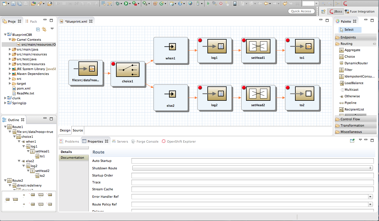
- Canvas—the large grid area on which routes are constructed
- Palette—the pane to the right of the canvas from which Enterprise Integration Patterns (EIPs) are selected
- Project view—the pane on the left side of the canvas, which can display multiple views of the active project. The pane defaults to Project Explorer, which displays the project's folders and files in an hierarchical tree format.NoteRed Hat recommends you to close the JMX Navigator view and then drag Outline view from the upper right side of the workspace to the lower left side, beneath Project Explorer, to provide optimal space for the route editor. Outline view displays, in an outline of EIP icons, the contents of the current
<camelContext>element in the routing context file. - Properties editor—the editor in which you configure the selected node's properties. It opens in a tab in the pane below the canvas.
Canvas
Palette
- Components—endpoint patterns that start or end a route
- Defined Endpoints—endpoint nodes that have been defined in the routing context
- Routing—patterns that direct the flow of messages based on specified criteria
- Control Flow—patterns that behave like control functions in a programming language. For example, some define loops, some handle error conditions, some handle transactions, and so on.
- Transformation—patterns that change the contents of a message as it passes through a route
- Miscellaneous—patterns that control the environment in which a route executes. For example, the
Threadspattern specifies the number of threads available.
Project Explorer
Outline view
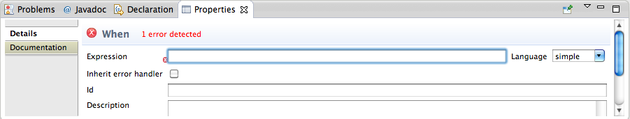
Properties editor
Figure 1.2. Properties editor's error reporting
Chapter 2. Debug Perspective
Overview
Figure 2.1. Debug perspective
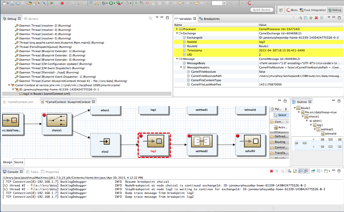
- Debug viewFor the running routing context, Debug view displays the debug stack.You can switch between breakpoints within the same message flow, listed under the
Camel Context at service:jmx:rmi://jndi/rmi://localhost:1099/jmxrmi/camelentry, to review and compare variable values in Variables view.Messages flows are identified by their unique breadcrumb ID, and the breadcrumb ID of each subsequent message flow is incremented by 2. For example, in Figure 2.1, “Debug perspective”, the breadcrumb ID for the first message flow isID-janemurpheysmbp-home-61339-11430424775526-0-1, so the breadcrumbID for the second message flow would beID-janemurpheysmbp-home-61339-11430424775526-0-3. - Variables viewFor each node in the routing context that has a breakpoint set, Variables view displays the value of the available variables when the breakpoint is hit. Each variable who's value changed since the preceding breakpoint is highlighted in yellow.You can change the value of editable variables to check whether such changes produce the expected results and to test the robustness of your routing context.You can also add variables to the watch list, so you can quickly and easily see whether their values change as expected at the expected point in the message flow.
- Breakpoints viewDisplays a list of the breakpoints set in the routing context, and shows whether they are enabled or disabled. You can enable and disable individual breakpoints by checking (enabling) or unchecking (disabling) them. This enables you to temporarily focus on nodes in your routing context that are behaving problematically.The
 button skips over disabled breakpoints to jump to the next active breakpoint in the routing context. In contrast, the
 button jumps to the next node of execution in the routing context, regardless of breakpoints.
- Camel Context: viewDisplays the running CamelContext:
<CamelId>.xmlin graphical mode. For nodes set with breakpoints, it shows the type of breakpoint set and whether the breakpoint is enabled or disabled. When a breakpoint is hit, its corresponding node on the canvas is outlined in red.To check a node's configuration, open Properties view and then select the node on the canvas in Camel Context: view. - Console viewDisplays the log output generated by the Camel debugger as it executes the routing context.
- Properties viewDisplays the properties set for the node selected on the canvas in CamelContext: view.
Related topics
| Part III, “Debugging Routing Contexts” |
| chapter "To Debug a Routing Context" in "Tooling Tutorials" |
Chapter 3. Fuse Integration Perspective
Overview
Figure 3.1. Fuse Integration perspective
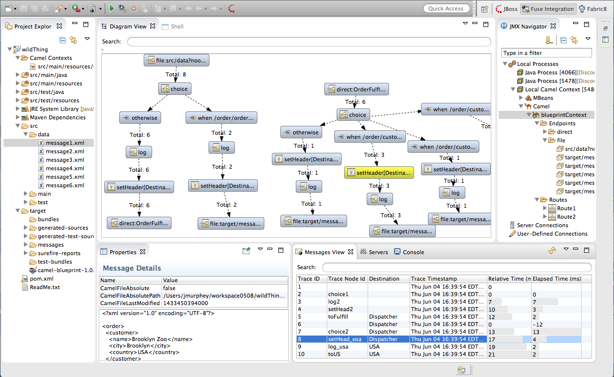
- Project Explorer—displays all of the projects known to the tooling. You can view all of the artifacts that make up each project. Project Explorer also displays all of the routing context
.xml. files for a project under its Camel Contexts node. This makes it easy for you to find and open the routing context file of any route included in a project. - JMX Navigator—lists the JMX servers and the infrastructure they monitor. It allows you to browse JMX servers and the pocesses they are monitoring. It also identifies instances of Red Hat processes.
- Diagram View—displays a graphical tree representing the node selected in JMX Navigator. When you select a process, server, endpoint, or other node, Diagram view shows the selected node as the root and branches down to its children and grandchildren.When you select a broker, Diagram View displays up to three children: connections, topics, and queues. It also shows configured connections and destinations as grandchildren.When you select a route, Diagram view displays all of the nodes in the route and shows the different paths that messages can take through it. It also displays timing metrics for each processing step in the route when route tracing is enabled.
- Shell view—Displays the command console of the connected container. You can control the container by entering commands in Shell view.
- Messages View—lists the messages that have passed through the selected JMS destination or through Apache Camel endpoints when route tracing is enabled.
- Servers view—displays a list of servers (Red Hat JBosss Fuse, Apache Karaf, or Apache ServiceMix) managed by the tooling. It displays their runtime status and provides controls for starting and stopping them and for debugging projects deployed on them.
- Properties view—displays the properties of the selected node.
- Console view— displays the console output for recently executed actions.
JMX Navigator
Messages view
Chapter 4. Fabric8 Perspective
Figure 4.1. Fabric8 perspective
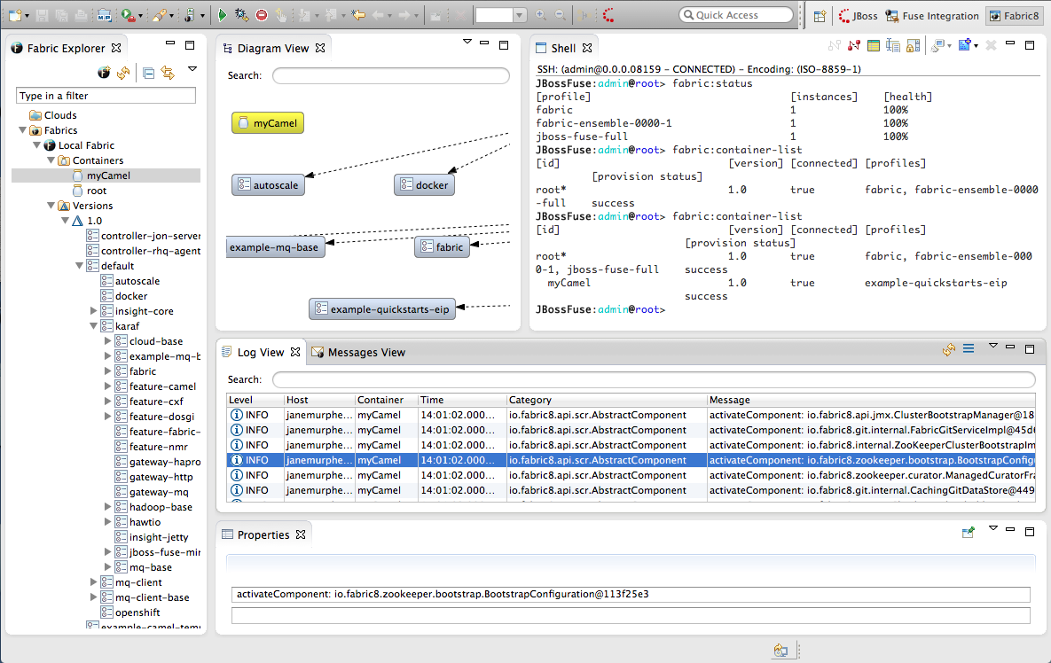
- Fabric Explorer—lists the fabrics and the containers, profiles, and versions of which they consist.
- Diagram View—provides a graphical representation of a node selected in Fabric Explorer.
- Shell— provides console access to any container running on the fabric.
- Log view—lists the log entries of the selected container or the selected JMX process.
- Messages View—lists the message instances that passed through the nodes in a selected route, after tracing was enabled on the route.
- Properties view—displays the properties of an object selected in Fabric Explorer.
Fabric Explorer
Diagram view
Log view
Messages view
Properties view
JMX viewer
Part II. Developing Applications
Chapter 5. Creating a New Fuse Project
Overview
Procedure
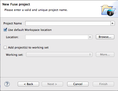
- Select → → to open the New Fuse Project wizard shown in Figure 5.1, “New Fuse Project Wizard's Project Location Page”.
Figure 5.1. New Fuse Project Wizard's Project Location Page
The wizard opens with the Use default workspace location option selected on the location page. - Enter the name of the Fuse project.
- Specify the location where the data for the project will be stored.
- To use the default workspace select Use default workspace location.
- To use an alternative location clear Use default workspace location and specify a new location in the provided field.Clicking
 opens a file browser.
- If you want to add the new project to an Eclipse working set, select Add project(s) to working set and enter the name of the working set.
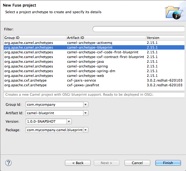
Figure 5.2. New Fuse Project wizard's details page
- Select a project type from the list.NoteThe route editor works with these project types:
- camel-archetype-activemqCreates a new Apache Camel project that configures and interacts with Apache ActiveMQ.
- camel-archetype-blueprintCreates a new Apache Camel project with support for OSGi blueprint that is deployment-ready for OSGi.
- camel-archetype-cxf-code-first-blueprintCreates a new Apache Camel project with Apache CXF code-first example using OSGi Blueprint.
- camel-archetype-cxf-contract-first-blueprintCreates a new Apache Camel project with Apache CXF contract-first example using OSGi Blueprint.
- camel-archetype-javaCreates a new Apache Camel project using Java DSL.You cannot edit Java DSL in the route editor.
- camel-archetype-springCreates a new Apache Camel project with added support for Spring DSL.
- camel-archetype-spring-dmDeprecated Creates a new Apache Camel project with added support for Spring DSL that is deployment-ready for OSGi.
- camel-archetype-webCreates a new Apache Camel web project that deploys the Camel routes as a WAR.
- cxf-jaxrs-serviceCreates a simple CXF JAX-RS web application service using Spring configuration.
- cxf-jaxws-javafirstCreates a project for developing a Web service starting from Java code.
- Enter a group ID for the project in the Group Id field, or accept the default.The tooling uses the group ID to form the first part of the dot-separated package name. For example, if you enter
Demofor the group ID, it appears in the Package field asDemo.. - Enter an artifact ID for the project in the Artifact Id field, or accept the default.The tooling uses the artifact ID as the name of the project and to form the second part of the dot-separated package name. For example, if you enter
BigRoutefor the artifact ID, it appears in the Package field asDemo.BigRoute. - Enter a version for the project in the Version field, or accept the default.
- If you want to change the package name generated for the artifacts, enter the new package name in the Package field.
- Click to create the Maven project, which contains starting point artifacts.
Resolving Maven dependency errors
- In Project Explorer, select the root project just created.
- Right-click it to open the context menu.
- Select →
- In the Update Maven Project wizard, check Force Update of Snapshots/Releases.
- Click OK.In the bottom, right corner of the workbench, you may see the progress status bar churning as missing dependencies are downloaded from the Maven repositories.
Related topics
| New Fuse Project |
| Red Hat JBoss Fuse Tooling Tutorials, To Create a New Route |
Chapter 6. Creating a New Camel XML file
Overview
camelContext element. The tooling includes a wizard that simplifies adding an Apache Camel context file to your project. It creates a new XML file that has all of the required namespaces preconfigured and a template camelContext element.
Procedure
- Select → → → → from the main menu to open the Camel XML File wizard, as shown in Figure 6.1, “Camel XML File wizard”.
Figure 6.1. Camel XML File wizard
- In RouteContainer, enter the location for the new file, or accept the default.You can click
to search for an appropriate location.
ImportantThe Spring framework and the OSGi Blueprint framework require that all Apache Camel files be placed in specific locations under the project's
META-INForOSGI-INFfolder:- Spring—
projectName /src/main/resources/META-INF/spring/ - OSGi Blueprint—
projectName /src/main/resources/OSGI-INF/blueprint/
- In File Name, enter a name for the new context file, or accept the default.The file's name cannot contain spaces or special characters, and it must be unique within the JVM.
- In Framework, accept the default, or select which framework the routes will use:
- Spring—for routes that will be deployed in Spring containers, non-OSGi containers, or as standalone applications
- OSGi Blueprint—for routes that will be deployed in OSGi containers
- Routes—for routes that you can load and add into existing
camelContexts
- Click .The new context file is added to the project and opened in the route editor.

Related topics
| New Camel XML File |
Chapter 7. Editing a routing context in the route editor
- Adding one or more routes to the routing context.
- Adding a starting point pattern to a route.
- Adding one or more endpoint patterns to a route.
- Adding one or more processor patterns that represent how messages will be transformed and routed between the starting point and endpoint(s).
- Connecting the patterns (referred to as nodes once they are placed on the canvas).
- Configuring the details for each of the endpoints and processors that make up the route.
- Adding any configuration beans to the context.
7.1. Adding routes to the routing context
Overview
camelContext element within an XML context file creates a routing context. The camelContext element can contain one or more routes, but the route editor's canvas can display only one of the routes at a time. Therefore the canvas is each route's delineator, and each route displayed on the canvas maps to a route element in the generated camelContext element.
camelContext.xml file that is defined either as camel-context.xml (Spring) or blueprint.xml (Blueprint). You can view and edit the contents of the camelContext.xml file in the route editor's Source view. In Design view, the route editor presents an empty canvas, which represents the empty route element. You can drag patterns from the Palette and drop them onto the canvas to create a route. The design time tooling updates the empty route element with XML code generated from the patterns you drop onto the canvas.
- From the menu bar, by opening the menu, and then selecting
- In Design view, by right-clicking the canvas or a node to access the context menu, and then selecting →
- In Source view, by adding a
<route/>element to the existing list within thecamelContextelement
Procedure
- Select one of the methods for adding a route.In Design view, a route icon appears in Outline view, and the Properties editor displays the list of the new route's properties for you to edit.
- In the Properties editor, enter an ID (for example, Route2) for the new route in the route's ID field.In Outline view, the new ID displays next to the new route icon.
- In the Properties editor, enter a description of the route in the Description field.
- On the menu bar, select → to save the changes you made to the routing context file.
Related topics
| Red Hat JBoss Fuse Tooling Tutorials, To Add a Content-Based Router |
| Red Hat JBoss Fuse Tooling Tutorials, To Add Another Route to the CBR Routing Context |
7.2. Adding patterns to a route
7.2.1. Drag and drop a pattern
Overview
Procedure
- In the Palette, locate the desired pattern.
- Select the pattern, drag it to the canvas, and then release the mouse button.NoteYou need not place the pattern in its intended location. You can easily move any node on the canvas by dragging it to a new location.
Related topics
| Section 7.5, “Rearranging patterns on the canvas” |
| Section 7.4, “Configuring a pattern” |
| Section 7.6, “Removing patterns from a route” |
7.2.2. Using the context menu
Overview
Procedure
- In the canvas, select the node to which you want to connect the new pattern.
- Right-click it to open the context menu.
- Select to display the list of patterns that can be connected to the selected node. The patterns are grouped according to function.
- Select the pattern to add to the route.
Related topics
| Section 7.5, “Rearranging patterns on the canvas” |
| Section 7.4, “Configuring a pattern” |
| Section 7.6, “Removing patterns from a route” |
7.3. Connecting patterns to make a route
Overview
route element in the context file until all nodes are linked together to form a complete route. A complete route typically consists of a starting endpoint, a string of processing nodes, and one or more destination endpoints.
Procedure
- On the canvas, select the source node to display its connector arrow.
- Click-drag the source node's connector arrow (
 ) to the target node.
The direction of the connection represents the direction messages flow between the nodes in the route.
) to the target node.
The direction of the connection represents the direction messages flow between the nodes in the route. - While hovering over the target node, release the mouse button to drop the connector on it.The route editor updates the
<route>element with the xml generated from the connection. You can view the xml in Source view. - When you are done, save your work by selecting → from the menu bar.
7.4. Configuring a pattern
Overview
- validating that all required properties have values
- drop-down lists for properties that have a fixed set of values
- drop-down lists that are populated with the available bean references from the Apache Camel Spring configuration
Procedure
- On the canvas, select the node you want to configure.The Details tab in the Properties editor lists all of the selected node's properties for you to edit. The Documentation tab describes the pattern and each of its properties.
- Edit the fields in the Properties editor to configure the node.
- When done, save your work by selecting → from the menu bar.
Related topics
7.5. Rearranging patterns on the canvas
7.5.1. Rearranging patterns by dragging them
Overview
Procedure
- Determine which node or nodes you want to move.
- Select one node, or select a group of nodes by dragging a box around them.
- Drag the node or nodes to their new location, then release the mouse button.
7.5.2. Automatically aligning patterns
Overview
Procedure
- Right-click the canvas to open the context menu.
- Select .
7.6. Removing patterns from a route
Overview
Procedure
- Select the node you want to delete.
- Right-click it to open the context menu.
- Select .
Related topics
| Section 7.2, “Adding patterns to a route” |
7.7. Disconnecting two patterns
Overview
Procedure
- Select the connector you want to delete.
- Right-click it to open the context menu.
- Select .
Related topics
| Section 7.3, “Connecting patterns to make a route” |
7.8. Deleting a route
Overview
Procedure
- If the routing context contains more than one route, first select the route you want to delete in Outline view.
- Right-click on the canvas to open the context menu.
- Select .
7.9. Adding beans and configuration
Overview
Procedure
- Open your routing context file in the route editor.
- Click the Source tab at the bottom of the route editor's canvas to switch to Source view, so you can edit the XML that defines the route.
- Enter the
beanelements needed by your route before thecamelContextelement.NoteUse theidattribute to identify the bean, not thenameattribute.ImportantDo not edit the contents of thecamelContextelement. Red Hat JBoss Fuse Tooling overwrites thecamelContextelement when changes are made to the route diagram in Design view. - Save your changes by selecting → on the menu bar.
- Click the Design tab at the bottom of the route editor's canvas to return to Design view and the route diagram.
Related topics
| Chapter 9, The Source View |
| Apache Camel Development Guide, Part IV Programming EIP Components |
7.10. Configuring the route editor
Overview
- The default language to use for expressions in EIPs
- The method for labeling nodes on the canvas
- The direction in which patterns flow on the canvas when creating routes
- Whether the canvas displays a grid overlay
- Colors used for various diagrammatic components
Procedure
- In JBoss Developer Studio, click → to open the Preferences dialog.
- Click → to show the Editor preferences.
- Select, from the drop-down list, the default language you want to use for expressions in EIP nodes.
- Click the checkbox next to If enabled the ID values will be use for labels if existing to enable or disable using node IDs as labels.
- Select, from the drop-down list, the direction in which you want the route editor to align the patterns in a route.
- Click the checkbox next to Show diagram grid in Routes Editor to enable or disable displaying the grid overlay on the canvas.
- Click to apply the changes to the Editor preferences.
- Click → to show the Colors preferences.
- For each component whose color you want to change, click its color icon to open the color palette, and then select a color from the palette.
- When done, click and then to close the Preferences dialog.You can restore the route editor's original color scheme at any time by returning to → and clicking .
Related topics
| Editor |
| Colors |
Chapter 8. Creating a new Apache Camel JUnit test case
Overview
Procedure
- In Project Explorer, select the
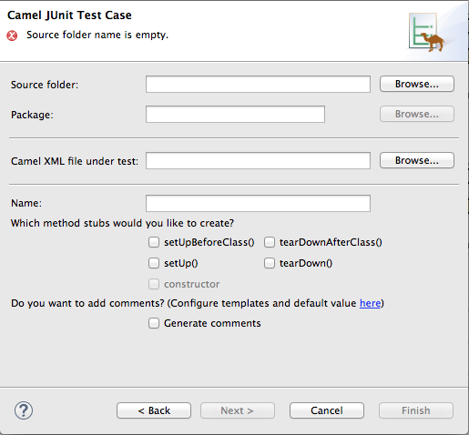
camel-context.xmlfile in your routing project. - Right-click it to open the context menu, and then select → to open the New Camel JUnit Test Case wizard, as shown in Figure 8.1, “New Camel JUnit Test Case wizard”.
Figure 8.1. New Camel JUnit Test Case wizard
Alternatively, you can open the wizard by selecting → → → → from the menu bar. - In Source folder, accept the default location of the source code for the test case, or enter another location.You can click
to search for a location.
- In Package, accept the default package name for the generated test code, or enter another package name.You can click
to search for a package.
- In Camel XML file under test, accept the default pathname of the routing context file that contains the route you want to test, or enter another pathname.You can click
to search for a context file.
- In Name, accept the default name for the generated test class, or enter another name.
- Select the method stubs you want to include in the generated code.
- If you want to include the default generated comments in the generated code, check the Generate comments box.
- Click
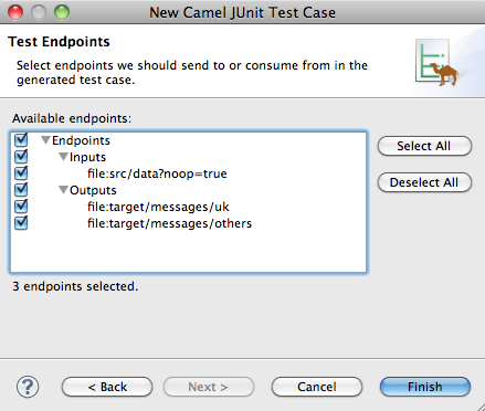
 to open the Test Endpoints page. For example, Figure 8.2, “New Camel JUnit Test Case page” shows a route's input and output file endpoints selected.
Figure 8.2. New Camel JUnit Test Case page
- Under Available endpoints, select the endpoints you want to test. Click the checkbox next to any selected endpoint to deselect it.
- Click
 .
NoteIf prompted, add JUnit to the build path.
.
NoteIf prompted, add JUnit to the build path.
src/test/java. The class implementing the test case opens in the Java editor.
Related topics
| New Camel JUnit Test Case |
| Test Endpoints |
| Red Hat JBoss Fuse Tooling Tutorials, To Test a Route with JUnit |
Chapter 9. The Source View
Figure 9.1. Source view
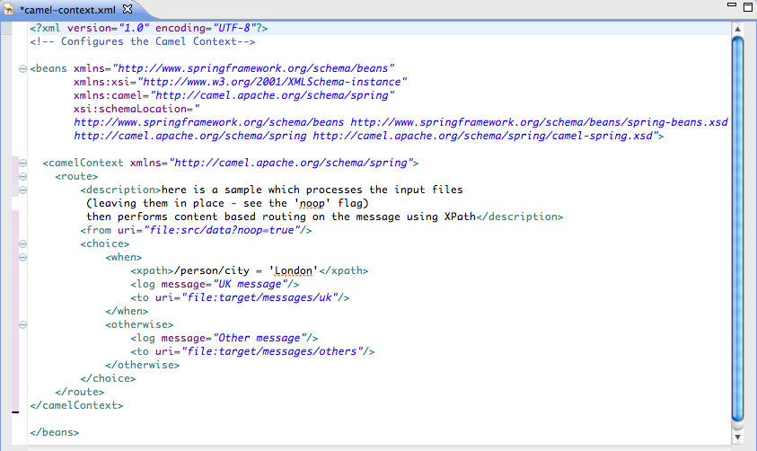
camelContext element in the routing context file, not all changes are preserved. Comments inserted into the camelContext element are lost upon switching to Design view.
Chapter 10. Running routes inside Red Hat JBoss Fuse Tooling
10.1. Running routes as a local Camel context
Overview
Procedure
- In Project Explorer, select a routing context file.
- Right-click it to open the context menu, and then select → .NoteSelecting directs the tooling to run the project without performing validation tests, which may be faster.
Result
Related topics
| Section 10.3.1, “Editing a Local Camel Context runtime profile” |
| Red Hat JBoss Fuse Tooling Tutorials, To Run a Route |
10.2. Running routes using Maven
Overview
Procedure
- In Project Explorer, select the root of the project .
- Right-click it to open the context menu, and then select → .
- The first time you run the project using Maven the Edit Configuration and launch editor opens, so you can create a Maven runtime profile.To create the runtime profile:
- Make sure the route directory of your Apache Camel project appears in the Base directory: field.For example on Linux the root of your project will be similar to
~/workspace/simple-router. - In the Goals: field, enter
camel:run. - Click and then .
- Subsequent Maven runs use this profile, unless you modify it between runs.
Results
Related topics
| Section 10.3.2, “Editing a Maven runtime profile” |
10.3. Working with runtime profiles
10.3.1. Editing a Local Camel Context runtime profile
Overview
main to invoke, the command line options passed into the JVM, the JRE to use, the classpath to use, any environment variables that need to be set, and a few other pieces of information.
- Camel Context File—specifies the name of the new configuration and the full path of the routing context file that contains your routes.
- Main—specifies the fully qualified name of the project's base directory, a few options for locating the base directory, any goals required to execute before running the route, and the version of the Maven runtime to use.
- JRE—specifies the JRE and command line arguments to use when starting the JVM.
- Refresh—specifies how Maven refreshes the project's resource files after a run terminates.
- Environment—specifies any environment variables that need to be set.
- Common—specifies how the profile is stored and the output displayed.
Accessing the Local Camel Context's runtime configuration editor
- In Project Explorer, select the camelContext file for which you want to edit or create a custom runtime profile.
- Right-click it to open the context menu, and then select → to open the Run Configurations dialog.
- In the context selection pane, select Local Camel Context, and then click
 at the top, left of the context selection pane.
- In the Name field, enter a new name for your runtime profile.
Figure 10.1. Runtime configuration editor for Local Camel Context
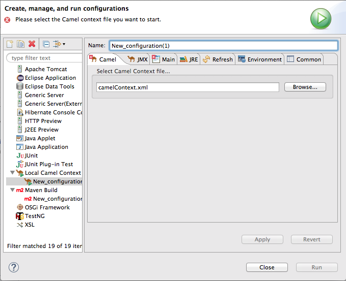
Setting the camel context file
Changing the command line options
-fa context-file
-fa context-fileChanging where output is sent
- Select the Common tab.
- In the Standard Input and Output pane, click the checkbox next to the File: field, and then enter the path to the file where you want to send the output.The , , and buttons facilitate building the path to the output file.
Related topics
| Section 10.1, “Running routes as a local Camel context” |
10.3.2. Editing a Maven runtime profile
Overview
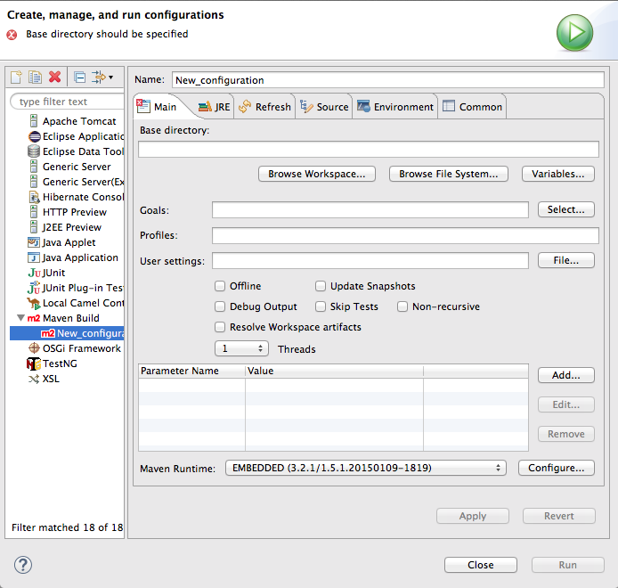
- Main—specifies the name of the new configuration, the fully qualified name of the project's base directory, a few options for locating the base directory, any goals required to execute before running the route, and the version of the Maven runtime to use.
- JRE—specifies the JRE and command line arguments to use when starting the JVM.
- Refresh—specifies how Maven refreshes the project's resource files after a run terminates.
- Environment—specifies any environment variables that need to be set.
- Common—specifies how the profile is stored and the output displayed.
Accessing the Maven runtime configuration editor
- In Project Explorer, select the root of the project for which you want to edit or create a custom runtime profile.
- Right-click it to open the context menu, and then select → to open the Run Configurations dialog.
- In the context selection pane, select m2 Maven Build, and then click
at the top, left of the context selection pane.
Figure 10.2. Runtime configuration editor for Maven
Changing the Maven goal
camel:run. It loads the routes into a Spring container running in its own JVM.
camel:embedded goal that loads the Spring container into the same JVM used by Maven. The advantage of this is that the routes should bootstrap faster.
Changing the version of Maven
Changing where the output is sent
- Select the Common tab.
- Click the checkbox next to the File: field, and then enter the path to the file where you want to send the output.The , , and buttons facilitate building the path to the output file.
Related topics
| Section 10.2, “Running routes using Maven” |
Chapter 11. Using the JBoss Fuse SAP Tool Suite
Abstract
11.1. Installing the JBoss Fuse SAP Tool Suite
Overview
Platform restrictions for SAP tooling
Prerequisites
- You will require an SAP Service Marketplace Account to download the JCo and IDoc client archives.
- Choose the appropriate JCo and IDoc libraries for your operating system.
- Only version 3.0.11 or greater of the JCo library is supported.
- Only version 3.0.10 or greater of the IDoc library is supported.
- For this installation procedure, you can leave the downloaded files in archive format. There is no need to extract the contents.
Procedure
- In JBoss Developer Studio, select → to open the Import wizard.
- In the Select screen of the Import wizard, select → , and click Next.
- The Install the JBoss Fuse SAP Tool Suite screen opens, which displays the instructions for downloading the JCo and IDoc libraries from the SAP Service Marketplace. Click Next.
- The Select JCo3 and IDoc3 Archive to Import screen opens. Next to the JCo Archive File field, use the Browse button to select the JCo archive that you downloaded from the SAP Service Marketplace. After selecting the JCo archive, the Archive Version and Archive OS Platform fields are automatically filled in, so that you can check whether the library you are installing has the correct version and OS platform.Next to the IDoc3 Archive File field, use the Browse button to select the IDoc archive that you downloaded from the SAP Service Marketplace.After selecting both archive files, click Finish.
- A new Install wizard (for installing Eclipse plug-ins) opens automatically. This wizard displays the following to plug-ins to be installed:
- JBoss Fuse SAP Tool Suite
- SAP JCo3 and IDoc3 Libraries
Make sure that both of these plug-ins are selected. Click Next.NoteThe SAP JCo3 and IDoc3 Libraries plug-in is dynamically constructed from the selected JCo and IDoc libraries. - The Install Details screen allows you to review the plug-ins to be installed. Click Next.
- The Review Licenses dialog opens. Select the I accept radiobutton option, and then click Finish.
- If you encounter a Security Warning dialog (warning of unsigned content), click OK to ignore the warning and continue installing.
- The Restart Eclipse dialog opens. Click OK to restart Eclipse.
11.2. Create and Test an SAP Destination Connection
Overview
Procedure
- If you have not already added the view to your perspective, select → → to open the dialog. Select and click . The view opens on the left of your perspective (under ).
- In the view, right-click on Destination Data Store and select New Destination, to open the Create Destination dialog.
- Enter a name for the destination in the New Destination Name field and click OK.
- Select the newly created destination in the Destination Data Store tree, so that its properties show up in the Properties view.
- In the Properties view, click on the Basic tab to configure the basic properties required to connect to an SAP destination. In this tab, fill in the following property fields to configure the connection:
- SAP Application Server
- SAP System Number
- SAP Client
- Logon User
- Logon Password
- Logon Language
These are standard SAP client connection properties. If you need more information about these settings, please consult the SAP documentation. - You are now ready to test the destination connection. In the SAP Connection view, right-click on the destination name and select Test.
- The Test Destination Connection dialog opens. Click Test.
- The dialog uses the current destination configuration settings to connect to the SAP server. If the test is successful, you will see the following message in the status area:
Connection test for destination 'YourDestination' succeeded.
Connection test for destination 'YourDestination' succeeded.Copy to Clipboard Copied! Toggle word wrap Toggle overflow Otherwise, an error report appears in the status area. - Click Close, to close the Test Destination Connection dialog.
11.3. Create and Test an SAP Server Connection
Overview
Procedure
- If you have not already added the view to your perspective, select → → to open the dialog. Select and click . The view opens on the left of your perspective (under ).
- In the view, right-click on Server Data Store and select New Server, to open the Create Server dialog.
- Enter a name for the server connection in the New Server Name field and click OK.
- Select the newly created server connection in the Server Data Store tree, so that its properties show up in the Properties view.
- In the Properties view, click on the Mandatory tab to configure the basic properties required for an SAP server connection. In this tab, fill in the following property fields to configure the connection:
- Gateway Host
- Gateway Port
- Program ID
- Repository Destination
- Connection Count
In the Repository Destination field, you can fill in one of the destination names from the Destination Data Store tree (see Section 11.2, “Create and Test an SAP Destination Connection”). An SAP server endpoint uses this destination to retrieve meta-data from a remotely hosted meta-data repository.The other properties are standard SAP server connection properties. Please consult the SAP documentation for more information. - You are now ready to test the server connection. In the SAP Connection view, right-click on the server connection name and select Test.
- The Test Server Connection dialog opens. Click Server.
- The dialog uses the current server configuration settings to start up a server endpoint and connect to the gateway host. If the test is successful, you will see the following messages in the status area:
Server state: STARTED
Server state: ALIVE
Server state: STARTED
Server state: ALIVE
Copy to Clipboard Copied! Toggle word wrap Toggle overflow If the test fails, the server status is reported asDEAD. - Click Stop, to shut down the test server.
- Click Close, to close the Test Server Connection dialog.
11.4. Export SAP Connection Configuration to a File
Overview
Procedure
- In the view, right-click on and select to open the dialog.
- Enter the location of the export file in the field, either directly or using the button.
- Select the using the drop-down menu. The supported file types are: or . Select the file type that matches the file type you will use to create your Camel routes.
- Click .
11.5. Create a New SAP Endpoint
Overview
Prerequisites
Procedure
- It is assumed that you already have a Fuse project and a Camel XML file to work with (which could either be in Blueprint XML or Spring XML format).
- Open your Camel XML file in the Camel editor. If you have already installed the JBoss Fuse SAP Tool Suite, you should be able to see the SAP components under the Components palette in the Camel editor. The following SAP components are provided by the tool suite:
- SAP IDoc Destination
- SAP IDoc List Destination
- SAP IDoc List Server
- SAP qRFC Destination
- SAP Queued IDoc Destination
- SAP Queued IDoc List Destination
- SAP sRFC Destination
- SAP sRFC Server
- SAP tRFC Destination
- SAP tRFC Server
In the Design view of the Camel editor, drag one of these components onto the canvas to create a new SAP endpoint in the current camelContext.NoteThe SAP Netweaver component does not belong to the JBoss Fuse SAP Tool Suite. It is hosted in the Apache Camel project. - Switch to the Source view of the Camel editor, by clicking on the Source tab at the bottom of the canvas. In this view, you can see the XML source of the routes.
- Open an exported SAP connection configuration file that you exported earlier (see Section 11.4, “Export SAP Connection Configuration to a File”), making sure that the type of the exported SAP connection configuration file matches the type of your Camel XML file (Blueprint XML or Spring XML).
- The SAP connection configuration data is encoded as a
beanelement, with theidvalue,sap-configuration. Copy thisbeanelement. - Return to the Source view of the Camel editor. Paste the
beanelement as a child of the rootbeanselement in the Camel XML file. - You might not need all of the entries in the SAP connection configuration. Delete any unneeded destination connection and server connection entries (
entryelements).NoteRemember that server connections usually also depend on a destination connection (for retrieving meta-data from a remote repository). So, even if you only need a server connection, do not delete all of the destination connection entries. - When specifying an SAP endpoint URI, you must embed either a destination name or a server connection name in the URI format. For example, the
sap-srfc-destinationcomponent has the following URI format:sap-srfc-destination:destinationName:rfcName
sap-srfc-destination:destinationName:rfcNameCopy to Clipboard Copied! Toggle word wrap Toggle overflow To reference a particular destination, use the value of the relevantentryelement'skeyattribute as thedestinationNamein this URI.
Chapter 12. Getting Started with Data Transformation
12.1. Fuse Transformation Tooling
12.2. Data Transformation Tutorial
Prerequisites
- JBoss Fuse tooling installed on JBoss Developer Studio. See Install Red Hat JBoss Developer Studio Integration Stack
- Maven installed and configured correctly. See Red Hat JBoss Fuse Maven Repositories
- the transformation quickstart applications downloaded and installed
Importing the starter quickstart application
- Right-click in Project Explorer to open the context menu.
- Select → .
- Expand the folder, and select .
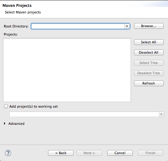
- Click to open the Maven Projects wizard.
- Click to find and select the root directory of the
starterquickstart application.If the browse operation finds multiple projects, make sure you select thestarterquickstart application. The full path to thestarterquickstart application appears in the pane. - Click .After the import operation finishes, the
starterproject appears in Project Explorer. - In Project Explorer, expand the
starterproject. - Double-click
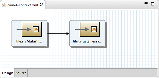
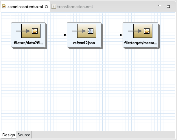
starter/src/main/resources/META-INF/spring/camel-context.xmlto open it in the route editor. - Click the Source tab to view the underlying XML.You can see that an XML file is produced from a source endpoint and a JSON file is consumed by a target endpoint.
- Click the Design tab to return to Design view.
- Remove the arrow connecting the source and target endpoints.NoteDo not save your project now. If you do, the endpoints will disappear because they are not connected, which makes the route invalid.
- If Console view is not already open, open it now by clicking → → .

Adding a data transformation node to the Camel route
- In the Palette, expand the Transformation drawer.
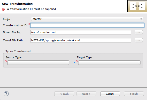
- Drag a Data Transformation component onto the canvas.The New Transformation wizard opens with the Project, Dozer File Path, and Camel File Path fields auto filled.
- Fill in the remaining fields:
- In Transformation ID, enter
xml2json. - For Source Type, select XML from the drop-down menu.
- For Target Type, select JSON from the drop-down menu.
- Click .The Source Type (XML) definition page opens, where you specify either an XML Schema (default) or an example XML Instance Document to provide the type definition of the source data:
- Leave XML Schema enabled.
- For Source file, browse to the location of the XML schema file or the XML instance file to use for the type definition of the source data, and select it (in this case,
abc-order.xsd).The XML Structure Preview pane displays a preview of the XML structure. - In Element root, enter
ABCOrder.The tooling uses this text to label the pane that displays the Source data items to map.The Source Type (XML) definition page should now look like this: - Click .The Target Type (JSON) definition page opens, where you specify the type definition for the target data.
- Click JSON Instance Document.In the Target File field, enter the path to the
xyz-order.jsoninstance document, or browse to it. The JSON Structure Preview pane displays a preview of the JSON data structure: - Click .


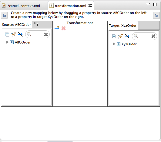
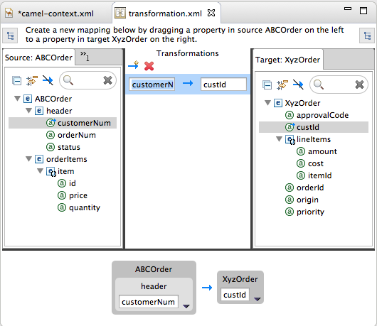
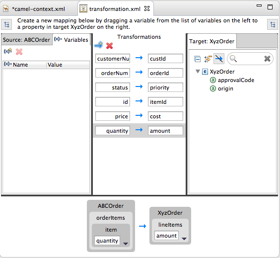
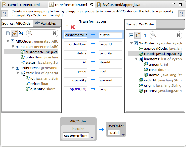
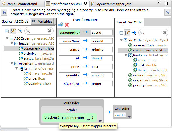
- Source—lists the available data items of the source
- Transformations—displays the mappings between the source and target data items
- Target—lists the available data items of the target
 custId" class="modal-img" loading="lazy">
custId" class="doc-image" loading="lazy">
custId" class="modal-img" loading="lazy">
custId" class="doc-image" loading="lazy">
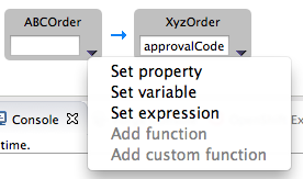
- Set property—Modify an existing mapping or map a simple data item to one in a collection (see the section called “Mapping a simple data item to a data item in a collection”)
- Set variable—Specify a constant value for a data item (see the section called “Mapping a constant variable to a data item”)
- Set expression—Map a data item to the dynamic evaluation of a specified expression (see the section called “Mapping an expression to a data item”)
- Add function—Modify the value of a mapped data item using a built-in function (see the section called “Adding a built-in function to a mapped data item”)
- Add custom function—Modify the value of a mapped data item using Java method you create or one you previously created (see the section called “Adding a custom function to a mapped data item”)
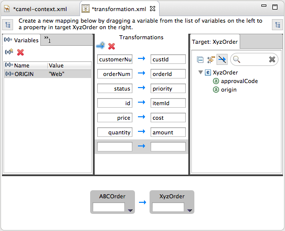
Mapping source data items to target data items
- Expand all items in the Source and Target panels located on left and right sides of the Transformations panel.
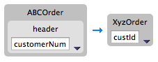
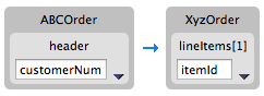
- Drag a data item from the Source panel and drop it on its corresponding data item in the Target panel.For example, drag the
customerNumdata item from the Source panel and drop it on thecustIddata item in the Target panel.The mapping appears in the Transformations panel, and the details of both the Source and Target data items appear below in Details view. - Continue dragging and dropping source data items onto their corresponding target data items until you have completed all basic mappings.In the
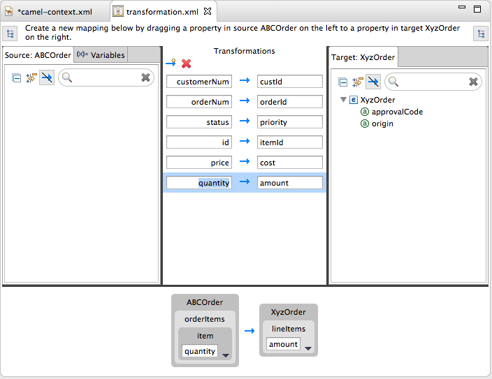
starterexample, the remaining data items to map are:Expand Source Target orderNumorderIdstatuspriorityiditemIdpricecostquantityamountNoteYou can map collections (data items containing lists or sets) to noncollection data items and vice versa, but you cannot map collections to other collections.NoteTo easily discover which data items are collections, click in both the Source and Target panels. (Brackets appear before the name of any data item that is part of a collection.) For an example, see Step 1 in the section called “Adding a custom function to a mapped data item”.
- Click
 on both the Source and Target panels to quickly determine whether all data items have been mapped.
Only data items that have not been mapped are listed in the Source and Target panels.In the
on both the Source and Target panels to quickly determine whether all data items have been mapped.
Only data items that have not been mapped are listed in the Source and Target panels.In thestarterexample, the remaining unmapped Target attributes areapprovalCodeandorigin. - Click the
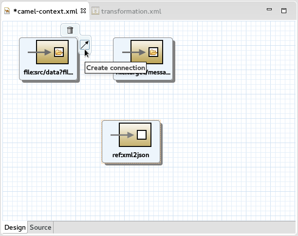
camel-context.xmltab to return to the route editor in Design view. - Hover your cursor over each endpoint to reveal its connecter arrow.
- Selecting the
file:src/data?fil...node, drag and drop its connector arrow onto theref:xml2jsonnode. Likewise drag and drop the connector arrow from theref:xml2jsonnode onto thefile:target/messa...node.Connecting the nodes on the canvas creates a valid Camel route, which you can now save. - Click → .

{"custId":"ACME-123","priority":"GOLD","orderId":"ORDER1","lineItems":[{"itemId":"PICKLE",
"amount":1000,"cost":2.25},{"itemId":"BANANA","amount":400,"cost":1.25
{"custId":"ACME-123","priority":"GOLD","orderId":"ORDER1","lineItems":[{"itemId":"PICKLE",
"amount":1000,"cost":2.25},{"itemId":"BANANA","amount":400,"cost":1.25Creating the transformation test file and running the JUnit test
- Right-click the
starterproject in Project Explorer, and select → → → . - Select to open the New Transformation Test wizard.
- In the New Transformation Test wizard, set the following values:
Expand Field Value Package exampleTransformation ID xml2json - Click .
- In Project Explorer, navigate to
starter/src/test/java/example, and open theTransformationTest.javafile. - Add the following code to the
transformmethod:startEndpoint.sendBodyAndHeader(readFile("src/data/abc-order.xml"), "approvalID", "AUTO_OK");startEndpoint.sendBodyAndHeader(readFile("src/data/abc-order.xml"), "approvalID", "AUTO_OK");Copy to Clipboard Copied! Toggle word wrap Toggle overflow - Click → .You can now run a JUnit test on your transformation file at any point in these tutorials.
- In Project Explorer, expand the
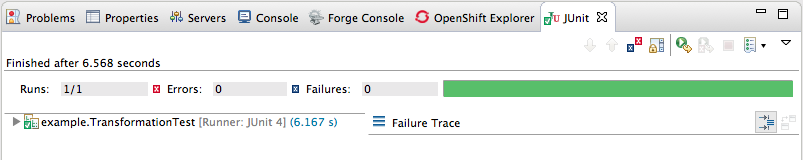
starterproject to expose the/src/test/java/example/TransformationTest.javafile. - Right click it to open the context menu, and select .The JUnit Test pane opens to display the status of the test. To avoid cluttering your workspace, drag and drop the pane in the bottom panel near Console view.
- Open Console view to see the log output.
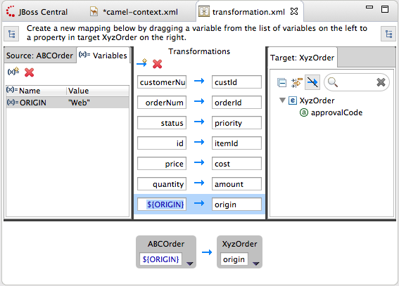
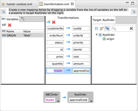
Mapping a constant variable to a data item
starter example, the target data item origin does not have a corresponding source data item. To map the origin attribute to a constant variable:
- In the Source panel, click the Variables tab to open Variables view.
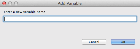
- In Variables view, click
 to open the Enter a new variable name dialog.
- Enter a name for the variable you want to create.For the
starterexample, enterORIGIN. - Click .The newly created variable
ORIGINappears in Variables view in the Name column and the default value "ORIGIN" in the Value column. - Click the default value to edit it, and change the value to
Web. - Press Enter.
- Drag and drop the new variable
ORIGINonto theorigindata item in the Target panel.The new mapping of the variable$(ORIGIN)appears in the Transformations panel and in Details view. - Run a JUnit test on your
TransformationTest.javafile. For details, see the section called “Creating the transformation test file and running the JUnit test”.Console view displays the json-formatted output data:{"custId":"ACME-123","priority":"GOLD","orderId":"ORDER1","origin":"Web", "approvalCode":"AUTO_OK","lineItems":[{"itemId":"PICKLE","amount":1000,"cost":2.25}, {"itemId":"BANANA","amount":400,"cost":1.25}]}{"custId":"ACME-123","priority":"GOLD","orderId":"ORDER1","origin":"Web", "approvalCode":"AUTO_OK","lineItems":[{"itemId":"PICKLE","amount":1000,"cost":2.25}, {"itemId":"BANANA","amount":400,"cost":1.25}]}Copy to Clipboard Copied! Toggle word wrap Toggle overflow
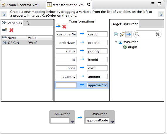
Mapping an expression to a data item
approvalCode data item, which lacks a corresponding source data item:
- Click
 to add an empty transformation map to the Transformations panel.
- From the Target panel, drag and drop the
approvalCodedata item to the target field of the newly created mapping in the Transformations panel.The approvalCode data item also appears in Details view's target box. - In Details view, click
 on the ABCOrder source box to open the drop-down menu.
Menu options depend on the selected data item's data type. The available options are bolded.
on the ABCOrder source box to open the drop-down menu.
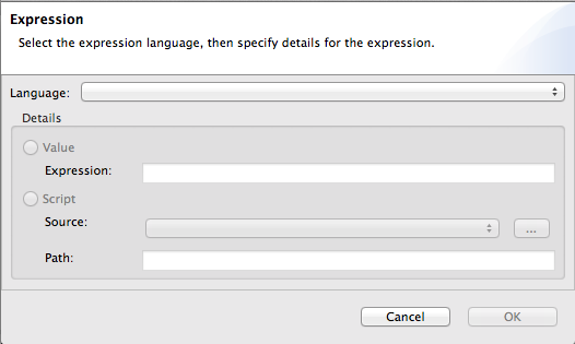
Menu options depend on the selected data item's data type. The available options are bolded. - Select to open the Expression dialog.
- In Language, select the expression language to use from the list of those available. Available options depend on the data item's data type.For the
starterexample, select . - In the Details pane, select the source of the expression to use.The options are Value and Script.For the
starterexample, click Value, and then enterApprovalID. - Click OK.Both Transformations panel and Details view display the new mapping for the target data item approvalCode.
- Run a JUnit test on your
TransformationTest.javafile. For details, see the section called “Creating the transformation test file and running the JUnit test”.Console view displays the json-formatted output data:{"custId":"ACME-123","priority":"GOLD","orderId":"ORDER1","origin":"Web", "approvalCode":"AUTO_OK","lineItems":[{"itemId":"PICKLE","amount":1000,"cost":2.25}, {"itemId":"BANANA","amount":400,"cost":1.25}]}{"custId":"ACME-123","priority":"GOLD","orderId":"ORDER1","origin":"Web", "approvalCode":"AUTO_OK","lineItems":[{"itemId":"PICKLE","amount":1000,"cost":2.25}, {"itemId":"BANANA","amount":400,"cost":1.25}]}Copy to Clipboard Copied! Toggle word wrap Toggle overflow
Adding a custom function to a mapped data item
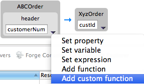
- Transformations panel, select the customerNum mapping to populate Details view.
- In Details view, click
on the ABCOrder source box to open the drop-down menu.
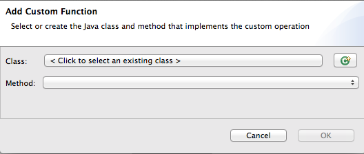
- Select to open the Add Custom Function page.
- Click
 next to the Class field to open the Create New Java Class wizard.
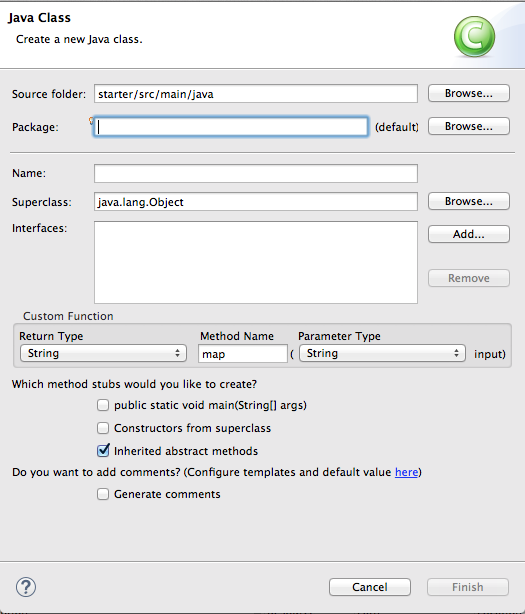
- Modify the following fields:
- Package—Enter
example. - Name—Enter
MyCustomMapper. - Method Name—Change map to
brackets.
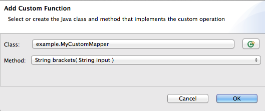
Leave all other fields as is. - Click Finish.The Add Custom Function page opens with the Class and Method fields auto filled:
- Click OK to open the
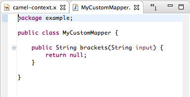
MyCustomMapper.javafile in the Java editor: - Edit the
bracketsmethod to change the last linereturn null;to this:return "[" + input + "]";
return "[" + input + "]";Copy to Clipboard Copied! Toggle word wrap Toggle overflow - Click the transformation.xml tab to switch back to the Transformation editor.Details view shows that the
bracketsmethod has been associated with the customerNum data item.Thebracketsmethod is executed on the source input before it is sent to the target system. - Run a JUnit test on your
TransformationTest.javafile. For details, see the section called “Creating the transformation test file and running the JUnit test”.Console view displays the json-formatted output data:{"custId":"[ACME-123]","priority":"GOLD","orderId":"ORDER1","origin":"Web", "approvalCode":"AUTO_OK","lineItems":[{"itemId":"PICKLE","amount":1000,"cost":2.25}, {"itemId":"BANANA","amount":400,"cost":1.25}]}{"custId":"[ACME-123]","priority":"GOLD","orderId":"ORDER1","origin":"Web", "approvalCode":"AUTO_OK","lineItems":[{"itemId":"PICKLE","amount":1000,"cost":2.25}, {"itemId":"BANANA","amount":400,"cost":1.25}]}Copy to Clipboard Copied! Toggle word wrap Toggle overflow
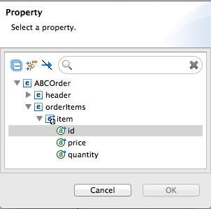
Mapping a simple data item to a data item in a collection
- In the Transformations panel, select the mapping id —> itemId to display the mapping in Details view.
- On the Source box, click
to open the drop-down menu, and select .
- In the Select a property page, expand the header node and select customerNum.
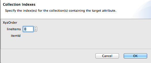
- Click to save the change and open the Collection Indexes page.
- In the Collection Indexes page, click the toggle button next to lineItems to increase its value to
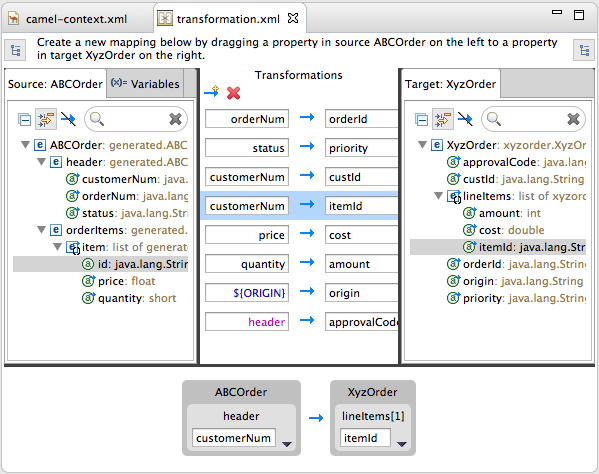
1.Indexes are zero-based, so a value of1selects the second instance of itemId in the collection. - Click to save the change and open the transformation.xml file.Notice that Details view shows customerNum mapped to the itemId of the second item in the lineItems collection.
- Run a JUnit test on your
TransformationTest.javafile. For details, see the section called “Creating the transformation test file and running the JUnit test”.Console view displays the json-formatted output data:{"custId":"[ACME-123]","priority":"GOLD","orderId":"ORDER1","origin":"Web", "approvalCode":"AUTO_OK","lineItems":[{"amount":1000,"cost":2.25}, {"itemId":"ACME-123","amount":400,"cost":1.25}]}{"custId":"[ACME-123]","priority":"GOLD","orderId":"ORDER1","origin":"Web", "approvalCode":"AUTO_OK","lineItems":[{"amount":1000,"cost":2.25}, {"itemId":"ACME-123","amount":400,"cost":1.25}]}Copy to Clipboard Copied! Toggle word wrap Toggle overflow
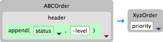
Adding a built-in function to a mapped data item
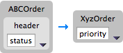
- In the Transformations panel, select the status to priority mapping to populate Details view.
- In the Source box, click
to open the drop-down menu, and select .
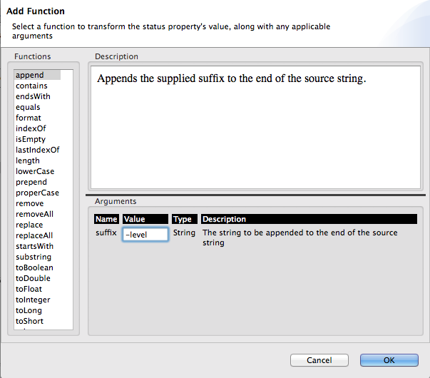
- In the Functions pane, select
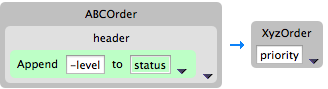
append, and in the Arguments pane, enter-levelfor the value ofsuffix.Thisappendfunction adds the specified suffix to the end of the status string before mapping it to the target priority data item. - Click .By default, Details view displays the results of adding the
appendfunction to the status data item in a user-friendly format. You can change this formatting by clicking the right-most
on the Source box, and selecting .
- Run a JUnit test on your
TransformationTest.javafile. For details, see the section called “Creating the transformation test file and running the JUnit test”.Console view displays the json-formatted output data:{"custId":"[ACME-123]","priority":"GOLD-level","orderId":"ORDER1","origin":"Web", "approvalCode":"AUTO_OK","lineItems":[{"amount":1000,"cost":2.25},{"itemId":"ACME-123", "amount":400,"cost":1.25}]}{"custId":"[ACME-123]","priority":"GOLD-level","orderId":"ORDER1","origin":"Web", "approvalCode":"AUTO_OK","lineItems":[{"amount":1000,"cost":2.25},{"itemId":"ACME-123", "amount":400,"cost":1.25}]}Copy to Clipboard Copied! Toggle word wrap Toggle overflow
Chapter 13. Using the Switchyard Tooling
13.1. JBoss Integration and SOA Development
JBoss Integration and SOA Development
- Creation of SwitchYard projects
- Configuration of SwitchYard capabilities
- Editing SwitchYard application configuration using a graphical editor
- Java2WSDL transformation
- XML catalog entries for SwitchYard configuration schema
- Support for workspace deployment of SwitchYard projects
Installing JBoss Developer Studio Integration Stack
- Honor all XML schema locationsAfter installation, go to → → → and disable
Honor all XML schema locations. This prevents erroneous XML validation errors from appearing onswitchyard.xmlfiles. - DTD warningImporting SwitchYard quickstarts into JBoss Developer Studio results in non-fatal warnings regarding
log4j.dtd. You can safely ignore them. To stop receiving the warning, make sure that either thelog4j.xmlorlog4j.propertiesfile is present before starting a project. - JavaSE-1.6 error messageWhen commencing a project, the warning "Build path specifies execution environment JavaSE-1.6" may appear. To disable this warning, go to your Java preferences and ensure that JavaSE-1.7 or JavaSE-1.8 is checked to support JavaSE-1.6 environments.
13.2. Running a SwitchYard Project on a JBoss Fuse Server
Adding a JBoss Fuse server
Installing the SwitchYard features on the server
- In the Servers view, select the JBoss Fuse server you just added, and click
 on the view's menu bar to start it up.
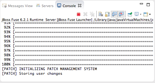
Console view opens and displays the server's startup progress:Wait until
on the view's menu bar to start it up.
Console view opens and displays the server's startup progress:Wait until[PATCH] Storing user changesappears at the end of the output. - Switch to Shell view, and install the
switchyard-*features, one after another, on the server:JBossFuse:admin@root> features:install switchyard-bean JBossFuse:admin@root> features:install switchyard-camel JBossFuse:admin@root> features:install switchyard-soap
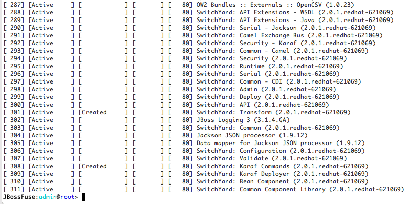
JBossFuse:admin@root> features:install switchyard-bean JBossFuse:admin@root> features:install switchyard-camel JBossFuse:admin@root> features:install switchyard-soapCopy to Clipboard Copied! Toggle word wrap Toggle overflow NoteTo see a list of all available SwitchYard-related features, enterfeatures:list | grep switchyard*. - Check that the
switchyard-*features are installed and active:JBossFuse:admin@root> osgi:list
JBossFuse:admin@root> osgi:listCopy to Clipboard Copied! Toggle word wrap Toggle overflow The end of the output should show the switchyard components installed and active :
Importing a SwitchYard quickstart project
/quickstarts/switchyard/.
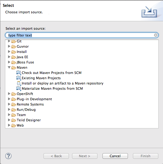
- Right-click in Project Explorer, and select → to open the Choose Import source dialog.
- In the Maven folder, select Existing Maven Projects.
- Click to open the Select Maven projects dialog.
- Click the button next to the Root Directory field to locate and select the
$FUSE_HOME/quickstarts/switchyard/bean-service. - In the Projects pane, make sure the box next to the
pom.xmlfile entry for theswitchyard-bean-serviceis checked to select it. - Click to start the import.The
switchyard-bean-serviceproject appears in Project Explorer.Wait a moment for the import process to finish.NoteSee the section called “Resolving Maven dependency errors” for details on what to do if you encounter Maven dependency errors, caused by failure to download all of the project's dependencies from the Maven repositories. - In Project Explorer, right-click the
switchyard-bean-serviceproject to open the context menu, and select .This option enables you to publish a switchyard project to the JBoss Fuse server, which you can do at any time now (for details, see the section called “Publishing a SwitchYard project to the server”).

Testing the SwitchYard quickstart project locally
- In Project Explorer, expand the
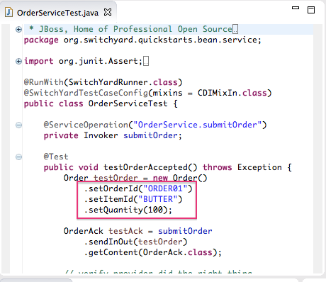
switchyard-bean-serviceproject to exposesrc/test/java/OrderServiceTest.javafile.If you want to take a look at the test code, double-click the file to open it in the Java editor. - In Project Explorer, right-click the
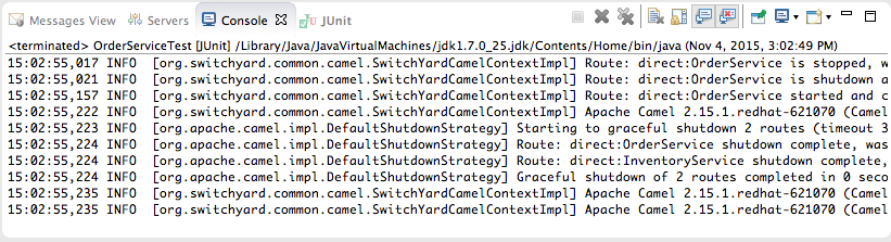
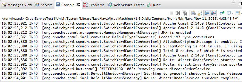
OrderServiceTest.javafile to open the context menu, and select → .Console view automatically opens and displays the log entries generated by the JUnit test.The last two log entries indicate that the test ran successfully against Apache Camel as expected. - Click the JUnit tab to open JUnit view.This test proves that the
switchyard-bean-servicesuccessfully builds and runs locally.NoteIf you failed to set the Execution environment to JavaSE-1.7 or JavaSE-1.8 when you defined the JBoss Fuse server, this test will fail. You can easily reset it by right-clicking theJRE System Librarynode in Project Explorer, and selecting → . In the Java Build Path dialog's Library tab, edit the current library to change the Execution environment setting to JavaSE-1.7 or JavaSE-1.8. (The library you select must be installed on your machine.) Then rerun the test.

Publishing a SwitchYard project to the server
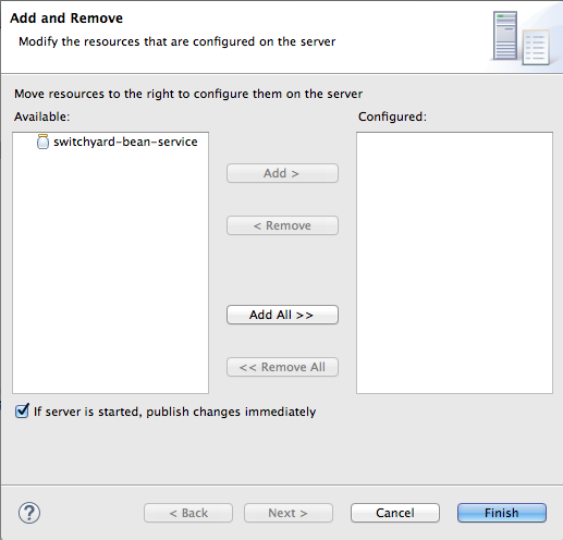
- In the Servers view, right-click the target server to open the context menu, and then select .When a project is ready for publishing, it appears in the Available column. For example:NoteThe option If server is started, publish changes immediately is enable by default. See the section called “Publishing Fuse projects automatically when resources change” for information on how this option works and on using other publishing options.
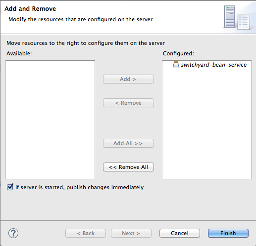
- Double-click the project in the Available column to move it to the Configured column.
- Click .Once publishing has finished, the project appears as a node under the server runtime node in the Servers view.Servers view shows that both the server runtime and the project are started and synchronized.NoteFor a server runtime, Synchronized means that all published resources on the server are identical to their local counterparts. For a published resource, Synchronized means that it is identical to its local counterpart.
- In Shell view, enter the command osgi:list to confirm that the
switchyard-bean-serviceproject is installed and active.


Testing the published SwitchYard project
- Open a web browser, and go to
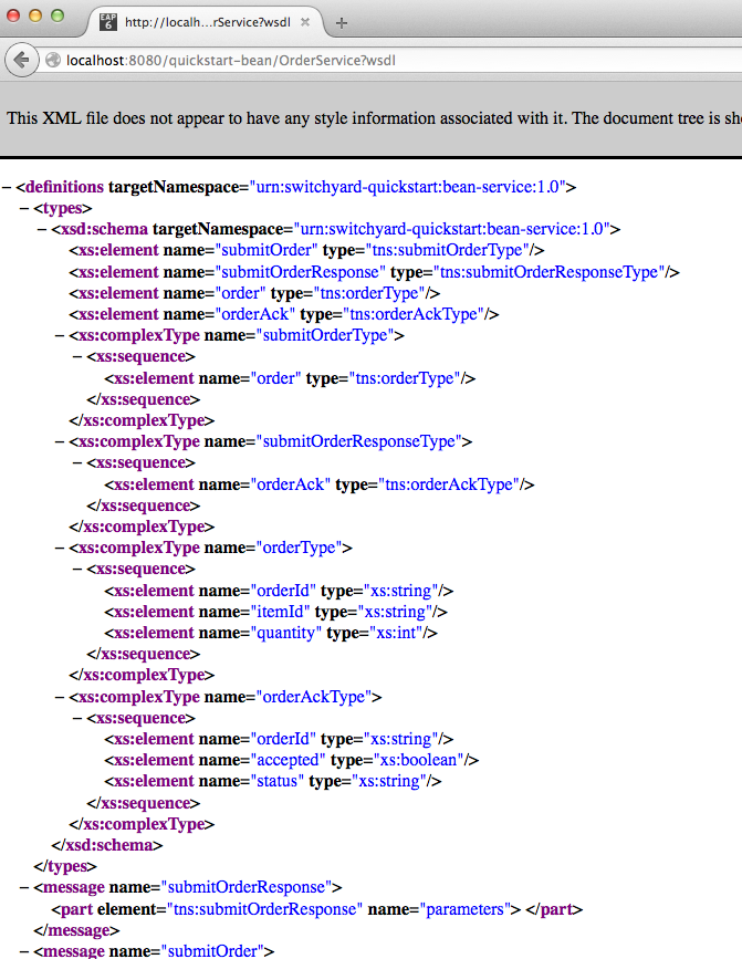
http://localhost:8181/cxf/to see the available SOAP services with OrderService in the list.This site provides a link to the OrderService's WSDL. - Click the link to the OrderService's WSDL to open it in the browser.
- Copy the URL displayed in the browser's address field.
- In JBoss Developer Studio, click → → , then scroll down to the JBoss Tools Web Services folder, and select .
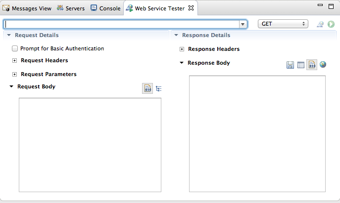
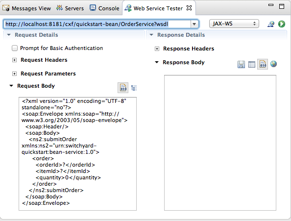
- Click the drop-down menu labeled GET, and select .The Request Body pane displays an example SOAP request message.
- Click
 next to
 to open the Specify the Source WSDL for the Web Service dialog, and then paste the URI you copied in Step 3 into the WSDL URI field.
The auto fills the remaining fields with the data retrieved from the WSDL.
to open the Specify the Source WSDL for the Web Service dialog, and then paste the URI you copied in Step 3 into the WSDL URI field.
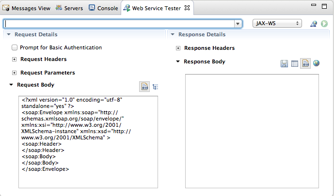
The auto fills the remaining fields with the data retrieved from the WSDL. - Click .The Web Service Tester displays the XML request message retrieved from the WSDL in the Request Body pane.You can enter values for the
<order>items<orderId>,<itemId>, and<quantity>to test the project's request and response services.NoteYou can discover what the data types are for each order item. In Project Explorer, double-clicksrc/test/java/OrderServiceTest.javafile to open it in the Java editor: - In the Request Body pane, click the value field of each order item and enter an appropriate value for it. For example:
- For <orderID> replace
?with ORDER10 - For <itemId> replace
?with BUTTER - For <quantity> replace
0with 1000
- Click
to the right of
to invoke the submitOrder operation. and populate the Response Body pane with an example response message.
Console view automatically opens to show the status of the submitOrder operation:
- Switch to the Web Service Tester tool and check the response message in the Response Body pane.


13.3. Running a SwitchYard Project on a JBoss Enterprise Application Server
- Install JBoss Fuse on the JBoss EAP serverFor details, see Installation of JBoss Fuse on JBoss EAP
- Add the server and its runtime definition to the tooling's Servers listOnce added to the list, the server appears in the Servers view, where you can configure it, start and stop it, and publish projects to it.
Adding a JBoss EAP server
- In Servers view, click the link No servers are available. Click this link to create a new server....NoteThis link appears in Servers view only when no server has been defined.
- Right-click in Servers view to open the context menu, then select → .
- On the menu bar, select → → → → .
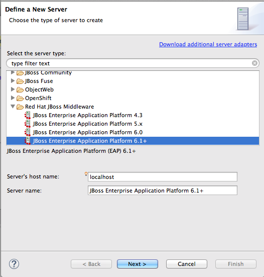
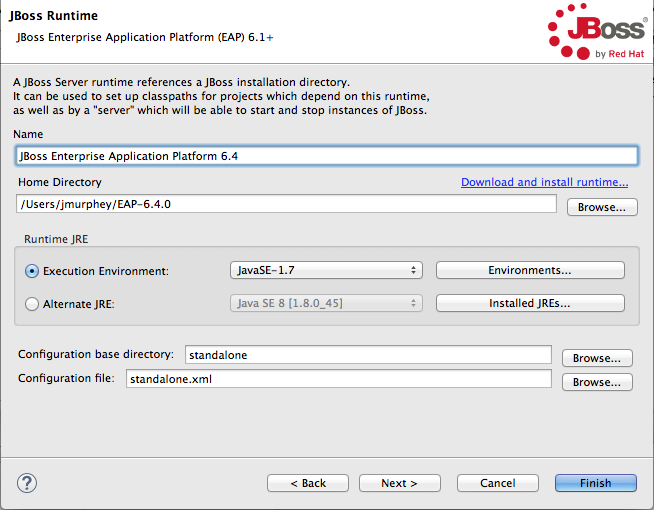
- In the Define a New Server dialog, select
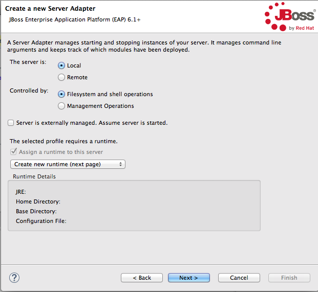
Red Hat JBoss Enterprise Application Platform 6.1+.Server's host name and Server name are auto filled by default. In Server name, you can enter a different name to use to identify the server in the Servers view. - Click to open the Create a New Server Adapter page.To specify that the server life-cycle is managed from outside the tooling, check Server is externally managed. Assume server is started..If you have not configured a runtime before, Create new runtime (next page) appears on the drop-down menu bar under The selected profile requires a runtime (as shown in the figure above). Otherwise, a previously configured runtime appears on the drop-down menu bar.NoteYou can assign the same runtime to multiple server instances, which enables you to quickly launch a server in debug mode or to configure other runtime settings.
- To use a previously created runtime with this server, click the drop-down menu and select it from the list (skip to Step 6).To create a new runtime, select Create new runtime (next page) from the list.
- Click to open the JBoss Runtime page.NoteIf the server is not already installed on your machine, you can install it now by clicking the link Download and install runtime... and following the site's download instructions. Depending on the site, you may be required to provide valid credentials before you can continue the download process.
- Configure the JBoss runtime:
- Accept the default for Name, or enter a different name.
- In Home Directory, enter the path where the server runtime is installed, or click to find and select it.
- Select the runtime JRE from the drop-down menu next to Execution Environment.If the version you want does not appear on the list, click , and then select the version from the list. The JRE version you select must be installed on your machine.
- Accept the defaults for Configuration base directory and Configuration file, or browse to the directory where the
.xmlconfiguration file to use is located.
- Click .The server appears in the Servers view.
Importing a SwitchYard quickstart project
$EAP_HOME/quickstarts/switchyard/.
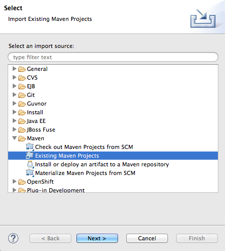
- Right-click in Project Explorer, and select → to open the Choose Import source dialog.
- In the Maven folder, select Existing Maven Projects.
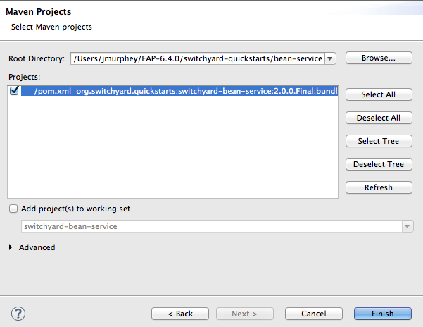
- Click to open the Select Maven projects dialog.
- Click the button next to the Root Directory field to locate and select the
$EAP_HOME/quickstarts/switchyard/bean-service. - In the Projects pane, make sure the
pom.xmlfile entry for theswitchyard-bean-serviceis selected. - Click to start the import.The
switchyard-bean-serviceproject appears in Project Explorer.Wait a moment for the import process to finish.
Testing a SwitchYard project locally
- In Project Explorer, expand the
switchyard-bean-serviceproject to exposesrc/test/java/OrderServiceTest.javafile.If you want to take a look at the test code, double-click the file to open it in the Java editor. - In Project Explorer, right-click the
OrderServiceTest.javafile to open the context menu, and select → .Console view automatically opens and displays the log entries generated by the JUnit test.These log entries indicate that the test ran successfully against Apache Camel as expected. - Click the JUnit tab to open JUnit view.This test proves that the
switchyard-bean-servicesuccessfully builds and runs locally.

Publishing a SwitchYard project to the server
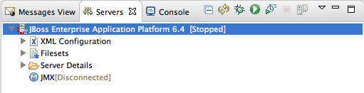
- In the Servers view, select the EAP 6.4 server you just added, and click
on the menu bar to start it.
- In the Servers view, right-click the server to open the context menu, and select .When a project is ready for publishing, it appears in the Available column.NoteThe option If server is started, publish changes immediately is enable by default. See the section called “Publishing Fuse projects automatically when resources change” for information on how this option works and on using other publishing options.
- Double-click the project in the Available column to move it to the Configured column.
- Click .Once publishing has finished, the project appears as a node under the server runtime node in the Servers view.Servers view shows that both the server runtime and the project are started and synchronized.NoteFor a server runtime, Synchronized means that all published resources on the server are identical to their local counterparts. For a published resource, Synchronized means that it is identical to its local counterpart.
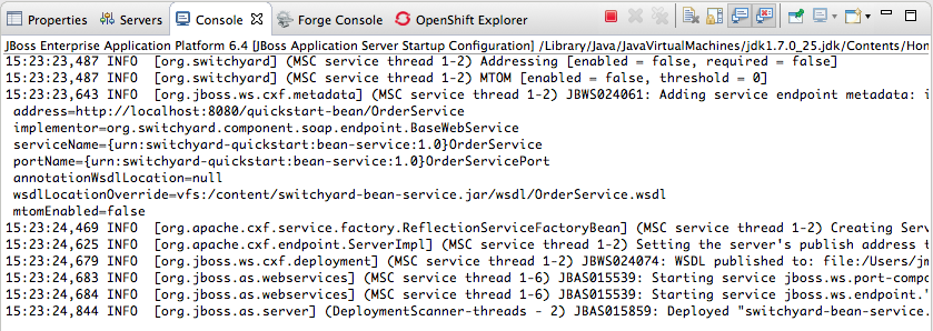
- Look at the log output in Console view to confirm that the
switchyard-bean-serviceproject is deployed and running:

Testing the published SwitchYard project
- From the log output in Console view, copy the address of the
bean-serviceproject'sOrderService.In the example we are using, the address ishttp://localhost:8080/quickstart-bean/OrderService. - Open a browser, and paste the address of the
OrderServicein the browser's address field. - Add
?wsdlto the end of the address, so it readshttp://localhost:8080/quickstart-bean/OrderService?wsdl. - Press Enter.The browser displays the WSDL for the
OrderService: - Copy the URL in the browser's address field.
- In JBoss Developer Studio, click → → , then scroll down to the JBoss Tools Web Services folder, and select .
- Click the drop-down menu labeled , and select .The Request Body pane displays an example SOAP request message.
- Click
next to
to open the Specify the Source WSDL for the Web Service dialog, then paste the URL you copied in Step 5 into the WSDL URI field.
The Web Service Tester auto fills the remaining fields with the data retrieved from the WSDL.
- Click .The Web Service Tester displays the XML request message retrieved from the WSDL in the Request Body pane.You can enter values for the
<order>items<orderId>,<itemId>, and<quantity>to test the project's request and response services.NoteYou can discover what the data types are for each order item. In Project Explorer, double-clicksrc/test/java/OrderServiceTest.javafile to open it in the Java editor: - In the Request Body pane, click the value field of each order item and enter an appropriate value for it. For example:
- For <orderID>, replace
?with ORDER10 - For <itemId>, replace
?with BUTTER - For <quantity>, replace
0with 1000
- Click
to the right of
to invoke the submitOrder operation. and populate the Response Body pane with an example response message.
Console view automatically opens to display the status of the submitOrder operation like this—
... INFO [stdout] (http-localhost/127.0.0.1:8080-2) |--- Validating Order object: [OrderID=ORDER10,
       ItemID=BUTTER, quantity=1000] ---|

... INFO [stdout] (http-localhost/127.0.0.1:8080-2) |--- Validating OrderAck object: [OrderID=ORDER10,
       accepted=true, status=Order Accepted [intercepted]] ---|
... INFO [stdout] (http-localhost/127.0.0.1:8080-2) |--- Validating Order object: [OrderID=ORDER10, ItemID=BUTTER, quantity=1000] ---| ... INFO [stdout] (http-localhost/127.0.0.1:8080-2) |--- Validating OrderAck object: [OrderID=ORDER10, accepted=true, status=Order Accepted [intercepted]] ---|Copy to Clipboard Copied! Toggle word wrap Toggle overflow —at the end of the Console output. - Switch to the Web Service Tester tool and check the response message in the Response Body pane.


Part III. Debugging Routing Contexts
- Setting conditional and unconditional breakpoints on nodes in the route editor
- Autolaunching the debugger and switching to Debug Perspective
- Interacting with the running routing context:
- Switch between breakpoints to quickly compare variable values of message instances
- Examine and change the value of variables of interest
- Add variables of interest to the Watch list to track them throughout the debug session
- Disable and re-enable breakpoints on-the-fly
- Track message flow graphically in the routing context runtime
- Examine Console logs to track Camel and debugger actions
.xml file to find the logic errors in it and fix them. Invoking the Camel debugger runs the routing context in debug mode and opens the Debug perspective (Chapter 2, Debug Perspective).
Chapter 14. Setting Breakpoints
Overview
.xml file must be open in the route editor's Design View.
- Unconditional breakpoints—triggered whenever one is encountered during a debugging session
- Conditional breakpoints—triggered only when the breakpoint's specified condition is met during a debugging session
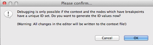
camelContext element and each node for which a breakpoint is set to have a unique ID. You can set IDs manually in a node's Properties editor or directly in the CamelContext file in Source view, or you can let Fuse Tooling generate and apply them automatically. The Please confirm... dialog opens whenever you set a breakpoint on a node that does not already have a unique ID.
Setting unconditional breakpoints
- Select a node whose state you want to examine during the debugging session.
- Click its
 icon to set an unconditional breakpoint.
- In the Please Confirm... dialog, click OK to have the Route Editor automatically generate and apply a unique ID to the <camelContext> element and to the node or nodes that need it, or click Cancel if you want to manually enter unique IDs in the <camelContext> element and to each node that needs one.
- Repeat these steps for each node on which you want to set an unconditional breakpoint.
Setting conditional breakpoints
- Select a node whose state you want to examine during the debugging session.
- Click its
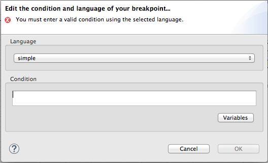
 icon to set a conditional breakpoint and open the Edit the condition and language of your breakpoint... dialog.
- Click the Language drop-down menu and select the expression langauge to use to create the condition that will trigger the breakpoint.Fuse Tooling supports twenty expression languages from which to choose. Except for
constant,method,property, andref, each of these languages provides variables for creating conditional expressions. - Click the Variables drop-down menu and select in sequence one or more of the language's supported variables to create the condition for triggering the breakpoint. The variables you select appear in the Condition text box.Alternatively, you can manually enter the expression directly into the Condition text box.
Disabling breakpoints
Deleting breakpoints
- Individual breakpoints—on the canvas, select the node whose breakpoint you want to delete, and click its
 icon.
icon.
- All breakpoints—right-click the canvas, and select
 Delete all breakpoints.
Related topics
| Chapter 15, Starting the Camel Debugger |
| chapter "To Debug a Routing Context" in "Tooling Tutorials" |
Chapter 15. Starting the Camel Debugger
Overview
Procedure
- In Project Explorer, select the routing context file you want to debug.
- Right-click it to open the context menu, and then select → .Fuse Tooling builds the Camel route, starts up Apache Camel, starts the routing context, enables JMX, starts the route(s) in the routing context, adds the breakpoints to the nodes, and enables the Camel debugger.The Camel debugger suspends execution of the routing context at the first breakpoint it encounters, and asks whether you want it to open the Debug perspective.
- Click Yes to open Debug perspective.Debug perspective opens with the routing context suspended at the first breakpoint in the running routing context.ImportantBreakpoints are held for a maximum of five minutes, after which debugging automatically resumes, moving on to the next breakpoint or to the end of the routing context if there are no more breakpoints.NoteTo see the console output, you'll need to open Console view if it was not open when you switched perspectives.NoteBy default, Debug perspective opens displaying Outline view, which provides the means to switch between separate routes in a routing context. If your routing context contains a single route, closing Outline view will provide more space to expand the other views, making it easier to access and examine debugger output.
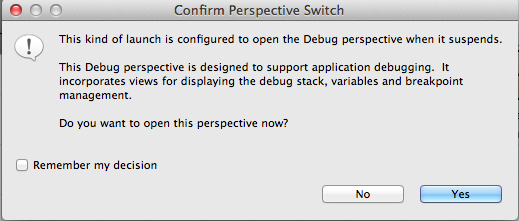
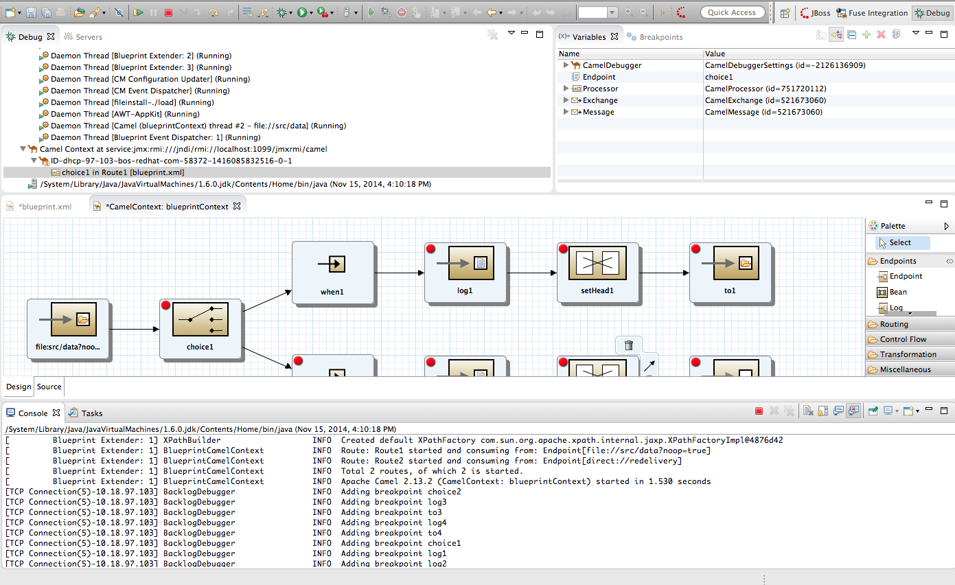
Watching message exchanges progress through the routing context
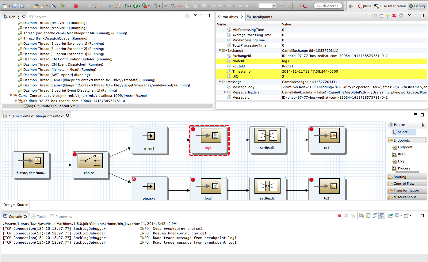
Related topics
| Chapter 16, Stopping the Camel Debugger |
| chapter "To Debug a Routing Context" in "Tooling Tutorials" |
Chapter 16. Stopping the Camel Debugger
Overview
Camel Context thread (both displayed in Debug view).
Terminating the Camel Debugger before the session ends
target/.CamelContextInDebug_xxxxxxxx_temp/camel-context.xml lines in the root project's src/main/resources/framework-INF/framework_name folder. InFuse Integration perspective, You may also see them in the project's Camel Contexts folder.
Related topics
| Chapter 15, Starting the Camel Debugger |
| chapter "To Debug a Routing Context" in "Tooling Tutorials" |
Chapter 17. Changing Variable Values
Overview
Procedure
- If necessary, start up the debugger. See Chapter 15, Starting the Camel Debugger.
- In Variables view, select a variable whose value you want to change, and then click its Value field.The variable's value field turns a lighter shade of blue, indicating it is in edit mode.NoteAlternatively, you can right-click the variable to open its context menu, and select to edit its value.
- Enter the new value and then click Enter.Console view displays an INFO level log entry noting the change in the variable's value (for example,
Breakpoint at node to1 is updating message header on exchangeId: ID-dhcp-97-16-bos-redhat-com-52574-1417298894070-0-2 with header: Destination and value: ChangedTarget). - Continue stepping through the breakpoints and check whether the message is processed as expected. At each step, check Debug view, Variables view, and the Console output.
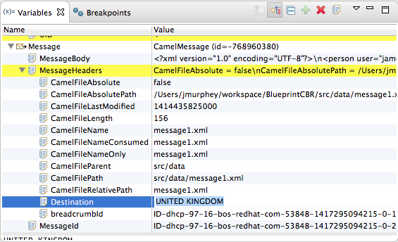
Related topics
| Chapter 19, Disabling Breakpoints in a Running Context |
| Chapter 18, Adding Variables to the Watch List |
| chapter "To Debug a Routing Context" in "Tooling Tutorials" |
Chapter 18. Adding Variables to the Watch List
Overview
Procedure
- If necessary, start up the debugger. See Chapter 15, Starting the Camel Debugger.
- In Variables view, right-click a variable you want to track to open the context menu.
- Select Watch.A new tab, Expressions, appears next to the Breakpoints tab.
- Click the Expressions tab to open it.Expressions view displays the name of the added variable and its current value.
- NoteThe variables you add will remain in the watch list until you remove them. To do so, right-click a variable in the list to open the context menu, and then click .
- With Expressions view open, step through the routing context to track how the value of each variable in the Watch list changes at each step in the routing context.
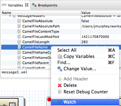

Related topics
| Chapter 17, Changing Variable Values |
Chapter 19. Disabling Breakpoints in a Running Context
Overview
camelContext element in the project's routing context file.
Disabling and enabling breakpoints in Breakpoints view
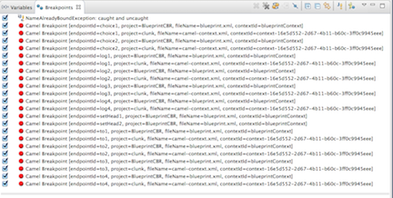

Removing breakpoint to3). Likewise, for each breakpoint you re-enable, Console view displays an INFO level log entry noting that it has been enabled (for example, Adding breakpoint to3).
Disabling and enabling breakpoints on the running CamelContext: canvas
- On the canvas, select the node with the breakpoint you want to disable; for example:NoteThe
icon denotes an unconditional breakpoint. A
icon denotes a conditional breakpoint.
- Click the
icon in the node's side bar.
The
icon replaces the
icon in the node's upper left corner, indicating that the breakpoint is now disabled:
The node's check box in Breakpoints view is clear, also indicating that the breakpoint is disabled:Console view contains a log of the event:NoteTo re-enable the breakpoint, select the node, and then click the
 icon in its side bar.
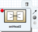


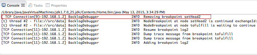
Deleting and resetting breakpoints on the running CamelContext: canvas
- On the CamelContext: <xxxxxx> canvas, select the node whose breakpoint you want to delete; for example, setHead_usa:Note that the node's breakpoint is enabled in Breakpoints view.NoteIn the above graphic, the dotted red line surrounding the setHead_usa node identifies the breakpoint on which the debugger is currently suspended.
- Click the
icon in the node's side bar:
The breakpoint is removed from the node on the canvas and also from the list of breakpoints in Breakpoints view:NoteTo reset the breakpoint, select the node, and then click the
or
icon in its side bar, depending on whether you want to set an unconditional or conditional breakpoint.


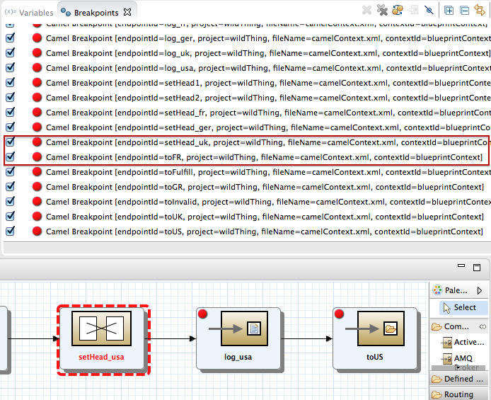
Related topics
| Chapter 14, Setting Breakpoints |
| the section called “Disabling breakpoints” |
| the section called “Deleting breakpoints” |
| chapter "To Debug a Routing Context" in "Tooling Tutorials" |
Part IV. Monitoring and Testing Applications
Chapter 20. JMX Navigator
Figure 20.1. JMX Navigator
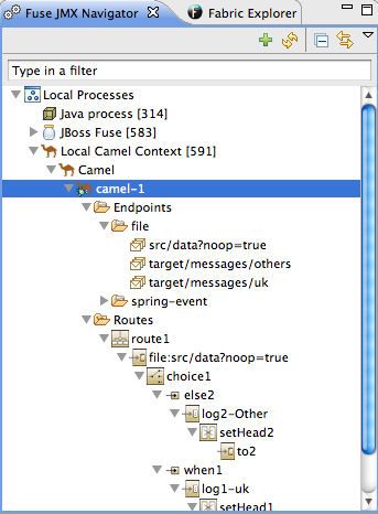
- Local Processes
- Server Connections
- User-defined connections
20.1. Viewing Processes in JMX
Overview
Viewing processes in a local JMX server
- Expand the Local Processes entry in JMX Navigator.
- Double-click one of the top-level entries under Local Processes to connect to the JMX server.
- Double-click it to open a connection.
- Click the
 icon that appears next to the entry to display the list of all components running in the JVM.
Viewing processes in alternate JMX servers
- Add the JMX server to JMX Navigator.
- Expand the server's entry in JMX Navigator using the
icon that appears next to the entry to display the list of all components running in the JVM.
20.2. Adding a JMX server
Overview
Procedure
- Click New Connection
 on the JMX Navigator tab .
- In the Create a new JMX connection wizard, select .
- Click .
- Select the Advanced tab.
- In the Name field, enter a name for the JMX server.The name can be any string. It is used to label the entry in the JMX Navigator tree.
- In the JMX URL field, enter the JMX URL of the server.
- If the JMX server requires authentication, enter your user name and password in the Username and Password fields.
- Click .The new JMX server is displayed as a branch in the JMX Navigator tree.
Chapter 21. Viewing a component's properties
Overview
Procedure
- Locate the node for the component in the Fuse JMX Navigator.You may have to expand nodes on the tree to locate low-level components.
- Select the Fuse component's node from the tree.
- Open the Properties view.The selected component's properties will be displayed in table format.You can use the Search box in Properties view to locate specific properties based on value.
Chapter 22. Browsing messages
Overview
- JMS destinations
- JMS routing endpoints
- Apache Camel routing endpoints
- SEDA routing endpoints
- Browse routing endpoints
- Mock routing endpoints
- VM routing endpoints
- DataSet routing endpoints
Procedure
- Select the JMS destination or endpoint from Fuse JMX Navigator.The list of messages is displayed in the Messages View.
- Select an individual message to inspect from the list of messages in the Messages View.Message details and content are displayed in the Properties view.
Related topics
| Section 23.3, “Tracing messages through a route” |
Chapter 23. Tracing Routes
- a message was improperly transformed
- a message failed to reach its destination endpoint
23.1. Creating test messages for route tracing
Overview
Procedure
- In Project Explorer, right-click the project to open the context menu.
- Select → to open the New File wizard.
- Enter or select the folder in which you want to store the message.
- In the File name field, enter a name for the message.
- Click .The new message opens in the XML editor.
- Fill in the contents (body and header text) of the message.
- On the menu bar, click → to save the test message.
Related topics
| Section 23.3, “Tracing messages through a route” |
| New Fuse Message |
| chapter "To Trace a Message Through a Route" in "Tooling Tutorials" |
23.2. Activating route tracing
Overview
Procedure
- In the Fuse JMX Navigator tree, select the routing context on which you want to start tracing.You can select any route in the context to start tracing on the entire context.
- Right-click it to open the context menu, and then select to start the trace.If is enabled on the context menu, then tracing is already active.
Related topics
| Section 23.3, “Tracing messages through a route” |
| Section 23.4, “Deactivating route tracing” |
23.3. Tracing messages through a route
Overview
Procedure
- Create one or more test messages as described in Section 23.1, “Creating test messages for route tracing”.
- Activate tracing for the route's routing context as described in Section 23.2, “Activating route tracing”.
- Drag one of the test messages onto the route's starting point.
- In the Fuse JMX Navigator tree, select the route being traced.The Messages View is populated with a list of messages representing the message at each stage in the traced route.
- Open Diagram View to see a graphical representation of the selected route.
- In the Messages View, select one of the messages.In Diagram View, the route step in which the selected message is sitting is highlighted. The Properties view displays the full details and content of the test message.
Related topics
23.4. Deactivating route tracing
Overview
Procedure
- In the Fuse JMX Navigator tree, select the routing context for which you want to deactivate tracing.You can select any route in the context to stop tracing for the context.
- Right-click it to open the context menu, and then select .If appears on the context menu, tracing is not activated for the routing context.
Related topics
| Section 23.2, “Activating route tracing” |
| Section 23.3, “Tracing messages through a route” |
Chapter 24. Managing JMS destinations
24.1. Adding a JMS destination
Overview
Procedure
- In the Fuse JMX Navigator tree, select either the Queues child or the Topics child in the broker node where you want to add a destination.
- Right-click it to open the context menu, and then select .
- In the naming dialog, enter a name for the destination.
- Click .The new destination appears in the tree.
Related topics
| Section 24.2, “Deleting a JMS destination” |
24.2. Deleting a JMS destination
Overview
Procedure
- In the Fuse JMX Navigator tree, select the JMS destination you want to delete.
- Right-click it to open the context menu, and then select .
Related topics
| Section 24.1, “Adding a JMS destination” |
Chapter 25. Managing routing endpoints
25.1. Adding a routing endpoint
Overview
Procedure
- In the JMX Navigator tree, select the Endpoints child in the routing context node where you want to add an endpoint.
- Right-click it to open the context menu, and then select .
- In the naming dialog, enter a URL defining the new endpoint.
- Click .The new destination appears in the tree.
Related topics
| Section 25.2, “Deleting a routing endpoint” |
25.2. Deleting a routing endpoint
Overview
Procedure
- In the JMX Navigator tree, select the endpoint you want delete.
- Right-click it to open the context menu, and then select .
Related topics
| Section 25.1, “Adding a routing endpoint” |
Chapter 26. Editing running routes
Overview
Procedure
- In the JMX Navigator tree, select the context containing the route(s) you want to edit.
- Right-click to open the context menu, and select .Route editor displays the context and all of its routes.
- Edit the route(s) as described in Part II, “Developing Applications”.
- When done, save the edited route.
- Select → to update the in-memory version of the routing context.Changes take effect immediately.
- >Select → to save the edited routing context in a new context file.
Related topics
Chapter 27. Managing routing contexts
27.1. Suspending a routing context
Overview
Procedure
- In the JMX Navigator tree, expand the project's Camel Contexts node, and select the routing context you want to suspend.
- Right-click it to open the context menu, and then select .NoteIf appears on the context menu, the context is already suspended.
Related topics
| Section 27.2, “Resuming a routing context” |
27.2. Resuming a routing context
Overview
Procedure
- In the JMX Navigator tree, expand the project's Camel Contexts node, and select the routing context you want to resume.
- Right-click it to open the context menu, and then select .NoteIf appears in the context menu, the context and its routes are running.
Related topics
| Section 27.1, “Suspending a routing context” |
Part V. Publishing Applications to a Container
Chapter 28. Managing servers
- Red Hat JBoss Fuse Server—versions 6.x
- Apache Karaf Server—versions 2.x, 3.0
- Apache ServiceMix Server—versions 4.5, 5.x
28.1. Adding a Server
Overview
/etc/users.properties file and add user information, in the form of user=password,role, to enable the tooling to establish an SSH connection to the server.
Procedure
- In Servers panel, click the link No servers are available. Click this link to create a new server....NoteThis link appears in Servers panel only when no server has been defined.
- Right-click in Servers panel to open the context menu, then select → .
- On the menu bar, select → → → → .
- In the Define a New Server dialog, expand the
JBoss Fusenode to expose the list of available server options: - Click the server you want to add.
- In Server's host name, accept the default (
localhost).NoteThe address oflocalhostis0.0.0.0. - In Server name, accept the default, or enter a different name for the runtime server.
- Click to open the server's Runtime definition page:NoteIf the server is not already installed on your machine, you can install it now by clicking the link Download and install runtime... and following the site's download instructions. Depending on the site, you may be required to provide valid credentials before you can continue the download process.
- Accept the default for Name.
- In Home Directory, enter the path where the server runtime is installed, or click to find and select it.
- Select the runtime JRE from the drop-down menu next to Execution Environment.If the version you want does not appear on the list, click the button and select the version from that list. The JRE version you select must be installed on your machine.NoteJBoss Fuse 6.2 requires either JRE versions 1.7 or 1.8.
- Leave the Alternate JRE option as is.
- Click to save the server's runtime definition and open its Configuration details page:
- Accept the default for SSH Port (
8101).The runtime uses the SSH port to connect to the server's Karaf shell. If this default is incorrect for your setup, you can discover the correct port number by looking in the server's installDir/etc/org.apache.karaf.shell.cfgfile. - In User Name, enter the name used to log into the server.In the case of Red Hat JBoss Fuse, this is a user name stored in the Red Hat JBoss Fuse installDir
/etc/users.propertiesfile.NoteIf the default user has been activated (uncommented) in the/etc/users.propertiesfile, the tooling autofills User Name and Password with the default user's name and password, as shown in Step 10. The default user is already activated in JBoss Fuse 6.2, but not in JBoss Fuse 6.0 or 6.1.If one has not been set, you can either add one to that file using the formatuser=password,role(for example,joe=secret,Administrator), or you can set one using the karafjaascommand set:jaas:realms—to list the realmsjaas:manage --index 1—to edit the first (server) realmjaas:useradd <username> <password>—to add a user and associated passwordjaas:roleadd <username> Administrator—to specify the new user's rolejaas:update—to update the realm with the new user information
If a jaas realm has already been selected for the server, you can discover the user name by issuing the commandJBossFuse:karaf@root>jaas:users. - In Password, enter the password required for User Name to log into the server.
- Click to save the server's configuration details.The server runtime will appear in Servers panel. For example:Expanding the server node exposes the server's JMX node:
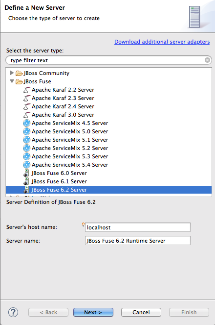
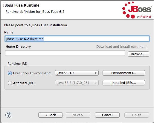
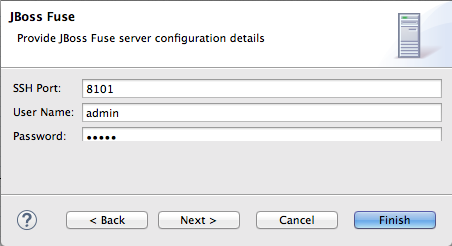
Related topics
| Define a New Server |
| New Server Configuration |
| Add and Remove |
28.2. Starting a Server
Overview
Procedure
- In the Servers panel, select the server you want to start.
- Click
 .
.
- Console view opens and displays a message asking you to wait while the container is starting; for example:NoteIf you did not properly configure the user name and password for opening the remote console, a dialog opens asking you to enter the proper credentials. See Section 28.1, “Adding a Server”.
- After the container has started up, Shell view opens to display the container's management console; for example:
- The running server appears in Servers panel:
- The running server also appears in JMX Navigator under Server Connections:
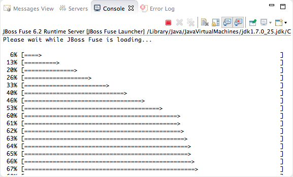
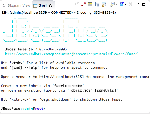

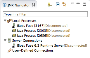
28.3. Connecting to a Running Server
Overview
Connecting to a running server in Servers panel
- In Servers panel, expand the server runtime to expose its
JMX[Disconnected]node. - Double-click the
JMX[Disconnected]node:
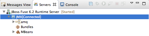
Connecting to a running server in JMX Navigator
- In JMX Navigator, select the server to which you want to connect under the Server Connections node.
- Double-click it:

Viewing bundles installed on the connected server
- In either the Servers panel or JMX Navigator, expand the server runtime tree to expose the Bundles node, and select it.
- The tooling populates Properties view with a list of bundles that are installed on the server:Using Properties view's Search tool, you can search for bundles by their Symbolic Name or by their Identifier, if you know it. As you type in the symbolic name or the identifier, the list updates, showing only the bundles that match the current search string.NoteThe Symbolic Name is the artifactId that you gave the project when you first created it. You can find the artifactId in the project's
pom.xmlfile.
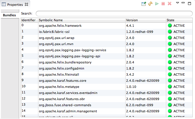
28.4. Disconnecting from a Server
Overview
Disconnecting from a server in Servers panel
- In Servers panel, expand the server runtime to expose its
JMX[Connected]node. - Right-click the
JMX[Connected]node to open the context menu, and then select .
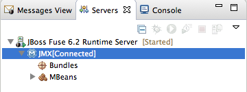
Disconnecting from a server in JMX Navigator
- In JMX Navigator, select the server from which you want to disconnect.
- Right-click it to open the context menu, and then select .
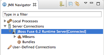
28.5. Stopping a Server
Overview
- from Servers panel
- from the server's remote console in Shell view
Using Servers panel
- In Servers panel, select the server you want to stop.
- Click
 .
.
Using the remote console
- Open the Shell view hosting the server's remote console.
- Type CTRL+D.
28.6. Deleting a Server
Overview
Deleting a server
- In Servers panel, right-click the server you want to delete to open the context menu.
- Select .
- Click .
Deleting the server's configuration
- On the menu bar, click → → .NoteOn Linux and Windows machines, you access Preferences through the Window menu.
- Expand the Server folder, and then select Runtime Environments to open the Server Runtime Environments page.
- From the list, select the runtime environment of the server that you previously deleted from Servers panel, and then click .
- Click .
Chapter 29. Publishing Fuse Projects to a Server
Abstract
Overview
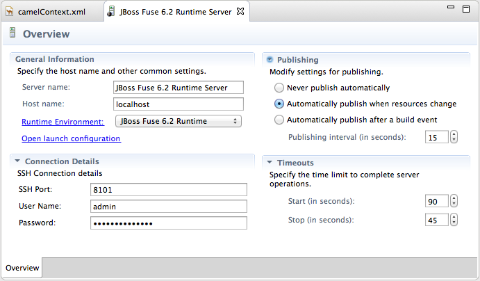
- Never publish automatically—You must select this option to manually publish projects.ImportantYou must also disable the If server started, publish changes immediately option on the server's Add and Remove page (for details see, the section called “Publishing Fuse projects manually”.
- Automatically publish when resources change—[default] Enable this option to automatically publish or republish a Fuse project when you save changes made to it. How quickly projects are published depends on the Publishing interval (default is 15 seconds).
- Automatically publish after a build event—For Fuse projects, works the same as Automatically publish when resources change.
Publishing Fuse projects automatically when resources change
- If necessary, start up the server runtime to which you want to publish a Fuse project. For details, see Section 28.2, “Starting a Server”.
- In the Servers panel, double-click the server runtime to open its Overview page.
- Expand Publishing, and then select Automatically publish when resources change.
- To increase or decrease the interval between publishing cycles, click the radio button next to Publishing interval (in seconds) up or down, as appropriate.
- In the Servers panel, right-click the server runtime to open the context menu, and then select .All resources available for publishing appear in the Available column.
- To assign a resource (in this case, the
wildThingFuse project) to the server runtime:- double-click it, or
- select it, and click .
The selected resource moves to the Configured column:At this stage, the time at which the assigned resource would actually be published would depend on whether the server runtime was running and on the Publishing interval setting. However, if the server was stopped, you would have to manually publish the project after you started the server (for details, see the section called “Publishing Fuse projects manually”). - Click the If server started, publish changes immediately option to enable it:This option ensures that the configured project is published immediately once you click . The Automatically publish when resources change option on the server runtime Overview page ensures that the configured project is republished whenever changes made to the local project are saved.
- Click .The project appears in the Servers panel under the server runtime node, and the server runtime status reports
[Started,Publishing...]:When publishing is done, the status of both the server runtime and the project report[Started,Synchronized]:NoteFor a server runtime,Synchronizedmeans that all published resources on the server are identical to their local counterparts. For a published resource,Synchronizedmeans that it is identical to its local counterpart.
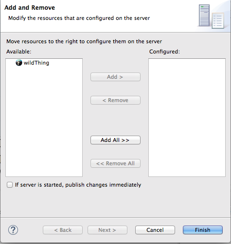
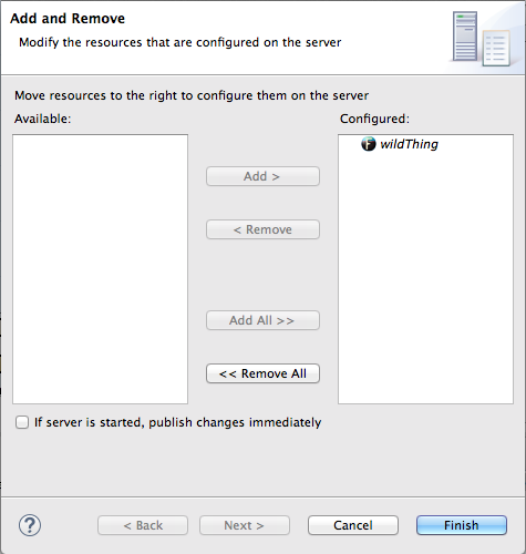
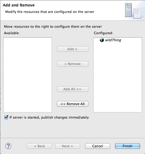
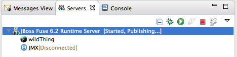
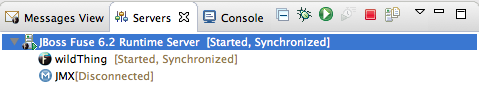
Publishing Fuse projects manually
- If necessary, start up the server runtime to which you want to publish a Fuse project. For details, see Section 28.2, “Starting a Server”.
- In the Servers panel, double-click the server runtime to open its Overview page.
- Expand Publishing, and then select Never publish automatically.
- If the Fuse project has already been assigned to the server runtime, make sure the If server started, publish changes immediately option is disabled.
- In the Servers panel, right-click the server runtime to open the context menu.
- Click to open the server's Add and Remove page.
- If the If server started, publish changes immediately option is enabled, disable it.
- Skip to Step 6.
- If the Fuse project has not been assigned to the server runtime, assign it now.
- Do not enable the If server started, publish changes immediately option.
- Click .The project appears in the Servers panel under the server runtime node, and the server runtime status reports
[Started]: - In the Servers panel, right-click the project's node (in this case, the Fuse project
wildThing) to open the context menu: - Select .During the publishing operation, the status of both the server runtime and the project report
[Started,Republish]:When publishing is done, the status of both the server runtime and the project report[Started,Synchronized]:NoteThe tooling does not support the option. Clicking results in a full publish.

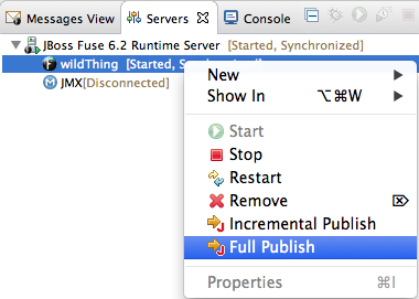

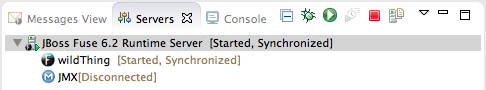
Verifying the project was published to the server
- Connect to the server runtime. For details see the section called “Connecting to a running server in Servers panel”.
- In the Servers panel, expand the server runtime tree to expose the Bundles node and select it.The tooling populates Properties view with a list of bundles that are installed on the server:
- To find your project's bundle, either scroll down to the bottom of the list, or start typing the bundle's symbolic name in Properties view's Search box.The bundle's symbolic name is the artifactId you gave the project when you created it. You can find the artifactId at the very beginning of the project's
pom.xmlfile. To open it in the tooling's XML editor, clickpom.xmlin Project Explorer, and then click the pom.xml tab in the XML editor.

Related topics
| Red Hat JBoss Fuse Tooling Tutorials, To Publish a Fuse Project to Red Hat JBoss Fuse |
Part VI. Working with Fabrics
Chapter 30. Setting up a Fabric Environment
Overview
- Providing the details for connecting to an existing fabric
- Connecting to the fabric
- Creating the containers that will host the various components of your distributed integration application
- Assigning each container one or more profiles, which provision containers by deploying and installing specified applications.
Opening the fabric perspective
Related topics
| Chapter 31, Specifying and Connecting to a Fabric |
Chapter 31. Specifying and Connecting to a Fabric
31.1. Adding fabric details
Overview
Procedure
- In Fabric Explorer, right-click to open the context menu, and then select to open the Fabric Details wizard, as shown in Figure 31.1.
Figure 31.1. Fabric Details wizard
- In Name, enter the name of the fabric to which you want to connect. The name you enter identifies the fabric whose location you specify in Jolokia URL, and this name will appear in Fabric Explorer.The default Name is Local Fabric.
- In Jolokia URL, enter the url, in the form
http://hostname:port/jolokia/, of the fabric to which you want to connect. This URL specifies the location of a fabric registry agent, whose default port is 8181.The default URL is http://localhost:8181/jolokia/. - In User name, enter the name used to log into the specified fabric.This is the user name that was either specified when the fabric was created or is defined in the Red Hat JBoss Fuse installDir
/etc/users.propertiesfile. In that file, user information is specified using this format:user=password,role(for example,admin=admin,Administrator).You can discover the user name by issuing the commandJBossFuse:karaf@root>jaas:users, if the Jaas realm has been selected for the fabric. - In Password, enter the password required for User name to log into the specified fabric.This is the password that was either specified for User name when the fabric was created or is defined in the Red Hat JBoss Fuse installDir
/etc/users.propertiesfile. - In Zookeeper Password, enter the password required for logging into the specified fabric's zookeeper registry.This is the password that was either specified when the fabric was created or is the password of the first user defined in the Red Hat JBoss Fuse installDir
/etc/users.propertiesfile.You can discover the Zookeeper password by issuing the commandJBossFuse:karaf@root>fabric:ensemble-password. - Click OK.The fabric's name appears in Fabric Explorer as a node beneath Fabrics.NoteBefore you can view or modify a fabric's containers, profiles or versions, you must connect to the fabric. For details see Section 31.2, “Connecting to a fabric”

Related topics
| Section 31.5, “Deleting a fabric's details” |
31.2. Connecting to a fabric
Overview
Procedure
- In Fabric Explorer, select the fabric to which you want to connect, then right-click it to open the context menu.
- Select .An expand arrow (
) appears next to the fabric you selected in Fabric Explorer.
- Click (
) to expand the fabric's tree and browse its containers, profiles, and versions.
From here, you can create and deploy new containers or modify existing ones by assigning them new profiles or modified versions of existing profiles.
Related topics
| Section 31.1, “Adding fabric details” |
31.3. Disconnecting from a fabric
Overview
Procedure
- In Fabric Explorer, select the fabric from which you want to disconnect, then right-click it to open the context menu.
- Select .The tooling closes the connection with the selected fabric.
31.4. Editing a fabric's details
Overview
Procedure
- In Fabric Explorer, select the fabric whose details you want to edit, and right-click it to open the context menu.
- Select to open the Fabric Details dialog, as shown in Figure 31.1, “Fabric Details wizard”.
- In Name, enter a new name for the fabric, if necessary.
- In Jolokia URL, enter the new url of the fabric, if necessary.
- In User name, enter a name with which the new user will log into the selected fabric, if necessary.
- In Password, enter the new password to use for logging into the selected fabric, if necessary.
- Click OK.
31.5. Deleting a fabric's details
Overview
Procedure
- In Fabric Explorer, select the fabric whose details you want to delete, then right-click it to open the context menu.
- Select .The tooling closes the connection with the selected fabric, and then deletes the fabric's details.
Related topics
| Section 31.1, “Adding fabric details” |
Chapter 32. Working with Fabric Containers
32.1. Creating a new child container
Overview
Procedure
- If necessary, in Fabric Explorer, expand the tree of the selected fabric in which you want to create the new child container.
- Right-click the target parent container to open the context menu, and then select .
Figure 32.1. Create Child Container wizard
- In Container name, enter a name for the new child container.We recommend that you replace the default name with a meaningful name that identifies the container's role or function.
- If multiple versions exist, you can select one from the Version drop-down list. Otherwise, accept the default value.
- Under Profiles, click the checkbox next to the profile or profiles you want to assign to the new child container.Profiles determine the function of containers; what applications they run. You can assign multiple profiles to a container, as long as the applications they install do not conflict with one another.ImportantDo not assign a base profile (one ending in
-base) to a container. - Click OK.The new child container appears in Fabric Explorer as a node under ContainersNoteSelecting the new container in Fabric Explorer populates its Profiles and Profile Details pages in Properties viewer.
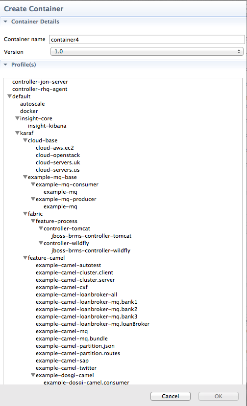
Related topics
| Section 33.1, “Creating a new profile” |
| Section 34.1, “Creating a new version of a profile” |
32.2. Creating a container on a remote host
Overview
Procedure
- If necessary, in Fabric Explorer, expand the tree of the fabric for which you want to create the new remote container.
- Right-click Containers to open the context menu, and then select .
Figure 32.2. Create Container via SSH wizard
NoteAn error icon ( ) marks required fields that lack a valid value, and the dialog banner displays the number of errors detected.
- In Container name, enter a name for the new container.We recommend that you replace the default name with a meaningful name that identifies the container's role or function.
- If multiple versions exist, you can select one from the Version drop-down list. Otherwise, accept the default value.
- In Host, enter the name or the IP address of the remote host.
- In User name, enter the name of a user authorized to log into the remote host.
- In Password, enter the password for User name.
- In Path, accept the default (~/containers/), or enter the path of the new container's location on the remote host.
- In Port, accept the default port number (22), or enter a new port number to use for establishing an ssh connection on the remote host.
- In SSH retries, accept the default (1), or enter the maximum number of retries to attempt at establishing an ssh connection on the remote host.
- In Retry delay, accept the default (1), or enter the delay, in milliseconds, between retry attempts.
- Under Profiles, click the checkbox next to the profile or profiles you want to assign to the container.Profiles determine the function of a container; what applications it runs. You can assign multiple profiles to a container, as long as the applications they install do not conflict with one another.ImportantDo not assign a base profile (one ending in
-base) to a container. - Click OK.The new container appears in Fabric Explorer as a container node under ContainersSelecting the new container in Fabric Explorers populates its Profiles and Profile Details pages in Properties viewer.
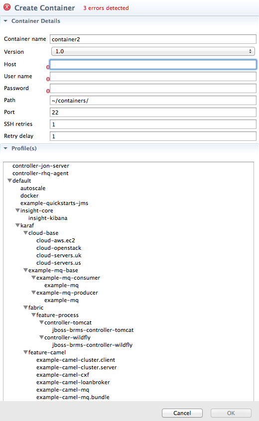
Related topics
| Section 33.1, “Creating a new profile” |
| Section 34.1, “Creating a new version of a profile” |
32.3. Creating a new container on a cloud
Overview
Procedure
- In Fabric Explorer, if necessary, expand the tree of the fabric for which you want to create the new container on the cloud. Right-click Containers to open the context menu.
- Select to open the Create Container in a Cloud wizard.
Figure 32.3. Create Container in a Cloud/Choose the Cloud page
NoteUnless the connection details for a cloud have already been added to the tooling, this dialog opens devoid of selections. You can add a cloud's connection details now by clicking Add Cloud details and following the procedure in Section 35.1, “Adding cloud details”. - Select a cloud from the list, and click to open the New Containers Details page.
Figure 32.4. New Containers Details page
NoteAn error icon (
) marks required fields that lack a valid value, and the dialog banner displays the number of errors detected.
- In Container name, enter a name for the new container.We recommend that you replace the default name with a meaningful name that identifies the container's role or function.
- If multiple versions exist, you can select one from the Version drop-down list. Otherwise, accept the default version.
- In Group, accept the default (fabric), or enter the group in which to start up the new container.
- In User, accept the default (admin), or enter the name of another user who is authorized to log into the new cloud container.This is the user that was either specified when the fabric was created or is defined in the Red Hat JBoss Fuse installDir
/etc/users.propertiesfile (see Section 31.1, “Adding fabric details”). - In Password, enter the pasword required for User to log into the new cloud container.This is the password that was specified for User when the fabric was created or is defined for the user in the Red Hat JBoss Fuse installDir
/etc/users.propertiesfile. - In Zookeeper Password, accept the default generated password for logging into the cloud container's zookeeper registry, or enter the zookeeper password that was used when the fabric was created.You can discover the zookeeper password by issuing the commmand
JBossFuse:karaf@root>fabric:ensemble-password. - In Hardware ID, select from the drop-down list the ID of the hardware archetype to use.Hardware archetypes specify the amount of memory and compute power available for running applications on machine images.ImportantThe next three fields provide two methods for specifying the software configuration (operating system, application server, and applications) you want to use. Either select an OS Family (and optionally a version), or select an Image ID.
- In OS Family, select from the drop-down list the family name of the operating system you want to use.If you select an OS Family, do not also select an Image ID.
- In OS Version, optionally select from the drop-down list the version for the operating system you selected.
- If you selected an OS Family, skip this step. Otherwise, in Image ID, select from the drop-down list the ID of the image template to use for the software configuration.NoteThe tooling starts an instance of the image in the cloud, and then installs a fabric agent and provisions the new agent with the selected profiles. Depending on the cloud provider, instantiation and provisioning could take some time.
- Under Profiles, select the profile or profiles you want to assign to the container.Profiles determine the function of containers—what applications they run. You can assign a container multiple profiles, as long as the applications they install do not conflict with one another.ImportantDo not assign a base profile (one ending in
-base) to a container. - Click OK.The new container appears in Fabric Explorer as a container node under ContainersNoteSelecting the new container in Fabric Explorer populates its Profiles and Profile Details pages in Properties viewer.
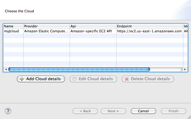
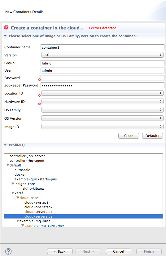
Related topics
| Chapter 35, Creating a Fabric in the Cloud |
| Section 33.1, “Creating a new profile” |
| Section 34.1, “Creating a new version of a profile” |
32.4. Starting a container
Overview
Procedure
- If necessary, in Fabric Explorer, expand the tree of the fabric whose container you want to start.
- Select the container and right-click it to open the context menu.
- Click .NoteTo check whether the tooling started the container, click Containers in Fabric Explorer, and open the Properties view. You should see something similar to Figure 32.5, where
mycamelExamplewas started and provisioned successfully.Figure 32.5. Container status in Properties view
The status indicators in the Status column of the Properties view indicate the startup state of the container, as shown Table 32.1:Expand Table 32.1. Container startup status Icon Meaning
Container stopped
Container started; analysis and provisioning in progress
Container started and provisioned successfully
Failure occurred during startup or provisioning
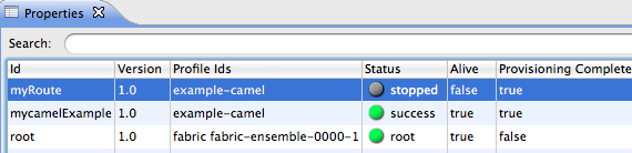
Related topics
| Section 32.6, “Stopping a container” |
32.5. Changing a Container's Profiles
Overview
Procedure
- Select the container.
- In the Properties view, select the Profiles tab.
- From the list, select the profile or profiles you want to deploy to the container by highlighting them.NoteTo select multiple profiles, hold down the CTRL key while you select them.
32.6. Stopping a container
Overview
Procedure
- If necessary, in Fabric Explorer, expand the tree of the fabric whose container you want to stop.
- Select the container and right-click it to open the context menu.
- Click .NoteTo check whether the tooling stopped the container, click Containers in Fabric Explorer, and open the Properties view. You should see something similar to Figure 32.6, where
myRoutewas stopped successfully.Figure 32.6. Container status in Properties view
For information on the meaning of the status indicators that might appear in the Status column of the Properties view, see Table 32.1, “Container startup status”.
Related topics
| Section 32.4, “Starting a container” |
| Section 32.7, “Deleting a container” |
32.7. Deleting a container
Overview
Procedure
- If necessary, in Fabric Explorer, expand the tree of the fabric whose container you want to delete.
- Click Containers to populate Properties view with a list of the fabric's containers.
- In Properties view, select the container you want to delete, and then click
 on the right-hand side of the toolbar.
Figure 32.7. Container selected for deletion in Properties view
- In the Destroy Container(s) dialog, click to delete the selected container.The tooling displays a message that removal is in progress. In Properties view, the container's status briefly changes to
stopped, and then the container disappears from the list. - In Fabric Explorer, open the fabric's context menu, and click to update Containers and remove the deleted container from the tree.NoteIf you have the Red Hat JBoss Fuse console open in Shell view, you can verify that the container and its configuration have been removed from the fabric by entering at the command line
fabric:container-list.
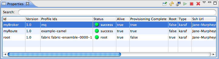
Related topics
| Section 32.6, “Stopping a container” |
| Section 32.1, “Creating a new child container” |
| Section 32.2, “Creating a container on a remote host” |
| Section 32.3, “Creating a new container on a cloud” |
Chapter 33. Working with Fabric Profiles
33.1. Creating a new profile
Overview
Procedure
- In Fabric Explorer, expand the fabric in which you want to create a new profile.
- Expand the fabric's tree to the level of the profiles, as shown in Figure 33.1.
Figure 33.1. Accessing the profiles
- Select the profile on which you want to base the new profile, and right-click it to open the context menu.ImportantBecause the selected profile is the parent of the new profile, the new profile inherits the selected profile's configurations, properties, features, repositories and bundles as well as those of the selected profile's ancestors. However, a child's configurations override an ancestor's when their configuration files have the same name.NoteNeither configuration files nor properties are visible within the tooling, but you can view them in the Red Hat JBoss Fuse Management Console. For details, see the Red Hat JBoss Fuse Management Console documentation at https://access.redhat.com/documentation/en-US/Red_Hat_JBoss_Fuse/.
- Select .
Figure 33.2. Create Profile dialog
- In Profile name, enter a name for the new profile.Use a name that is descriptive of the new profile's function.
- Click to create and save the new profile.The new profile is added to the list of profiles in Fabric Explorer, under its parent profile.
- In Fabric Explorer, select the new profile to populate the Properties editor with the new profile's properties information and profile details.
- In the Properties editor, click the Details tab.
Figure 33.3. Profiles page
On the Profiles page, you can add, delete, or edit features, the repositories from which features are downloaded, and bundles. You can also add or remove parent profiles. Profiles can have multiple parents, and they inherit the qualities of eachFeatures are files that aggregate references to interdependent or related bundles that together define a feature. Typically, you'd use bundles only if the feature they define is not already included in a features file. For more information on bundles and features, see Deploying Features.Child profiles inherit everything (configurations, properties, features, repositories, and bundles) from their immediate parents and from all of their parents' ancestors. When the child's and any ancestor's configuration file have the same name, the child's configuration file replaces the ancestor's file. Otherwise, configurations are cumulative.NoteThe Profiles page displays only the features, repositories, and bundles added by the child profile, not those contributed by the profile's parents or other ancestors. The Parents pane shows (highlighted) the profile's immediate parents only. - Make the changes you want to the new profile to configure it.Changes are automatically saved as you make them.NoteIn Fuse Integration perspective, you can easily add a Fuse project to the new profile by dragging it from Project Explorer and dropping it onto the new profile in Fabric Explorer. When you do, the fabric tooling builds the project, runs all tests, installs the project in the new profile, and uploads the profile into the fabric's internal Maven repository. Because profiles are stored in a fabric's internal repository, they cannot be shared across other fabrics.ImportantIf you drop your project on a fabric container, rather than on a profile, the next time that container is provisioned, your project is wiped out.You can now assign the new profile to a container.
- In Fabric Explorer, select the container to which you want to assign the new profile.The fabric tooling populates the Properties editor with the container's properties information and profile details.
- Open the container's Details tab, and then select the new profile in the Profiles list.
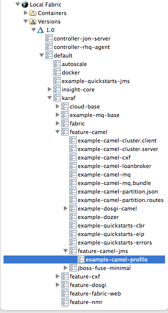
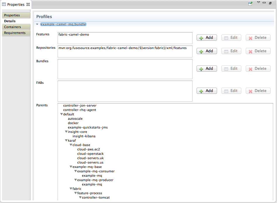
Related topics
| Section 34.1, “Creating a new version of a profile” |
33.2. Deleting a profile
Overview
Procedure
- In Fabric Explorer, expand the fabric which contains the profile you want to delete.
- Expand the fabric's tree to the level of versions, and then expand the version that contains the target profile.
- Select the target profile, and right-click it to open the context menu.
- Select .
Chapter 34. Working with Versions
34.1. Creating a new version of a profile
Overview
Creating a new version
- In Fabric Explorer, select the fabric in which you want to create a new version.
- Expand the fabric's tree to the level of Versions, shown in Section 33.1, “Creating a new profile”.
- Select Versions, and then right-click it to open the context menu.
- Select .
- In the Create Version wizard, enter a new version or accept the default value.The default version is always a minor increment of the highest-numbered version. So, if the highest-numbered version is 1.3, the new version will default to 1.4, and all of the profiles in version 1.3 will be copied into version 1.4.ImportantVersion names are important! The tooling sorts version names based on the numeric version string, according to major.minor numbering, to determine the version on which to base a new one. You can safely add a text description to a version name as long as you append it to the end of the generated default name like this:
1.3<.description>. If you abandon the default naming convention and use a textual name instead (for example,Patch051312), the next version you create will be based, not on the last version (Patch051312), but on the highest-numbered version determined by dot syntax. - Click .The tooling copies all of the base version's profiles into the new version and displays the new version in Fabric Explorer, directly under the base version.
Modifying profiles in the new version
- In Fabric Explorer, expand the newly created version.
- Select a profile that you want to modify.The tooling populates the Properties editor with the profile's details for you to edit.
- In the Properties editor, click the Details tab to access the Profiles page.
- Make the changes you want to the new profile to configure it.Changes are automatically saved as you make them.
Related topics
| Section 33.1, “Creating a new profile” |
34.2. Setting a container's version
Overview
Procedure
- In Fabric Explorer, select the container whose profiles you want to change.
- Right-click it to open the context menu, and then select .The submenu lists all available versions.
- Click the version you want to assign the selected container.The container is immediately provisioned with the new version of any profile assigned to it.
Chapter 35. Creating a Fabric in the Cloud
- Have established an account with a cloud provider
- Provide the tooling the account details for connecting to the cloud
- Specify the details required for creating the fabric and the machine image on which it will run
35.1. Adding cloud details
Overview
Procedure
- In Fabric Explorer, right-click Clouds to open the context menu, and then select .
Figure 35.1. Cloud Details wizard
NoteAn error icon (
) marks required fields that lack a valid value, and the dialog banner displays the number of errors detected.
- In Name, enter a name for the cloud.ImportantThe next three fields provide two methods for specifying the provider's information. You select either a provider's name, or you select both an API and its endpoint.
- In Provider name, select the name of the cloud provider from the drop-down list.If you select a provider name, the tooling autofills Api name and Endpoint with the selected provider's information, so you can skip to Step 6.
- In Api name, select from the drop-down list the name of the API you want to use.This list displays only APIs that have been installed on your local machine or environment.
- In Endpoint, enter the uri of the web service that exposes the API you selected in Step 4.If you have an on-premises, private cloud installed, you need to get this uri from the cloud administrator.
- In Identity, enter the account identifier supplied by the cloud provider.For example, for Amazon Elastic Compute Cloud (EC2) accounts, you'd enter the Access Key ID.
- In Credential, enter the account password supplied by the cloud provider.For example, for Amazon Elastic Compute Cloud (EC2) accounts, you'd enter the Secret Access Key.
- In Owner, for EC2 only, enter the id assigned to a custom image.This option is EC2-specific and applies only to custom images. To query or use a custom image, you must enter the owner id assigned to it by EC2; otherwise, the image will not appear in the list of instances.
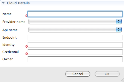
Related topics
| Section 32.3, “Creating a new container on a cloud” |
35.2. Specifying fabric details
Overview
Procedure
- In Fabric Explorer, right-click to open the context menu, and then select .
- On the wizard's Choose the Cloud page, select the cloud from the list, and then click to open the wizard's Fabric Details page.
Figure 35.2. Fabric Details page
NoteAn error icon (
) marks required fields that lack a valid value, and the dialog banner displays the number of errors detected.
You may have to wait a few seconds while the tooling retrieves the location, hardware, and image IDs from your cloud provider to populate the wizard's corresponding fields. - In Fabric Name, accept the default name, or enter a different name for the new fabric.
- In Container name, accept the default name, or enter a different name for the new container that will host the fabric registry.
- In Group, accept the default name, or enter a different name for the group in which to start up the new fabric registry container.
- In User, accept the default user name, or enter a different user name to use for logging into the new fabric registry container.
- In Password, enter the password required for User to log into the specified fabric.
- In Zookeeper Password, accept the default, generated password for logging into the cloud fabric's zookeeper registry, or enter a different password.
- In Location ID, select from the drop-down list the ID of the region in which the machines you want to use are located.
- In Hardware ID, select from the drop-down list the ID of the hardware archetype you want to use.Hardware archetypes specify the amount of memory and compute power available for running applications on machine images.ImportantThe next three fields provide two methods for specifying the software configuration (operating system, application server, and applications) you want to use. Either select an OS Family (and optionally a version), or select an Image ID.
- In OS Family, select from the drop-down list the family name of the operating system you want to use.If you select an OS Family, do not also select an Image ID.
- In OS Version, optionally select from the drop-down list the version for the operating system you selected.
- If you selected an OS Family, skip this step. Otherwise, in Image ID, select from the drop-down list the ID of the image template to use for the software configuration.
- In Maven proxy URI, accept the default URI, or enter the URI to the Maven proxy repository you want to use.
- Click .The tooling creates the container, then provisions it with all of the bundles, features, and profiles required to create a fabric registry. This process can take up to ten minutes. When it's done, the container specified in Step 4 appears in Fabric Explorer as a node under Fabrics.NoteIt's a good idea to access your cloud account and verify that the new fabric registry container is up and running.
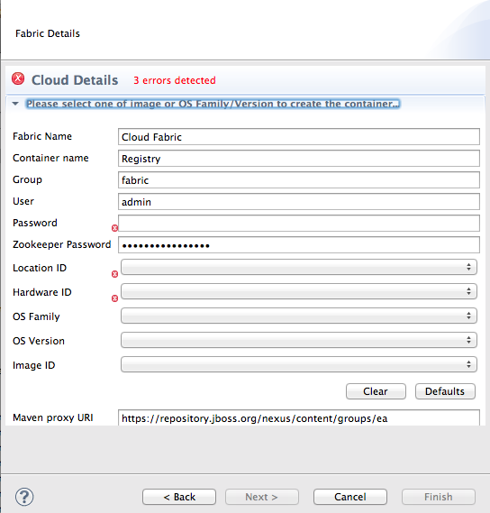
Related topics
| Section 35.1, “Adding cloud details” |
| Section 32.3, “Creating a new container on a cloud” |
Appendix A. Wizard field references
Name
New Camel XML File — Creates a new XML file for editing routes with the route editor
Properties
| Name | Default | Description |
|---|---|---|
| RouteContainer | Specifies the folder into which the new file will be placed. | |
| File Name | camelContext.xml | Specifies the name of the new routing context file. |
| Framework | Spring | Specifies whether the context file is intended to be used in a Spring container or in an OSGi container that supports Blueprint or to be added to into existing camelContexts. |
META-INF folder:
- Spring—
projectName /src/main/resources/META-INF/spring/ - OSGi Blueprint—
projectName /src/main/resources/META-INF/blueprint/
Related topics
| Chapter 6, Creating a New Camel XML file |
Name
New Fuse Project — Creates a new Fuse project
Properties
| Name | Default | Description |
|---|---|---|
| Project Name | Specifies the name of the new project. | |
| Use default Workspace location | Enabled | Specifies whether to create the new project in the default workspace. |
| Location | Specifies the full path to an alternate workspace when the default workspace location option is disabled. | |
| Add project(s) to working set | Disabled | Specifies whether to add the new project to one or more established working sets. |
| Working set | Specifies the working sets in which to add the new project when the working set option is enabled. |
Related topics
| Chapter 5, Creating a New Fuse Project |
Name
New Fuse Project — Creates a new Fuse project
Properties
| Name | Default | Description |
|---|---|---|
| Archetype | Specifies the Maven archetype to use to create the new project. | |
| Group ID | Specifies the group ID Maven uses when generating the new project. This ID is mapped to the POM file's groupId element. | |
| Artifact ID | Specifies the artifact ID Maven uses when generating the new project. This ID is mapped to the POM file's artifactId element. | |
| Version | 1.0.0-SNAPSHOT | Specifies the version name Maven uses when generating the new project. You can accept the default version name, or enter a new one. This value is mapped to the POM file's version element. |
| Package | <groupID>.<artifactID> | Specifies the package name for the generated artifacts. You can accept the default package name, or enter a new one. |
Related topics
| Chapter 5, Creating a New Fuse Project |
Name
New Fuse Message — Creates a new message to use in route tracing.
Properties
| Name | Default | Description |
|---|---|---|
| Parent Folder | The selected folder | Specifies the folder into which the new message file will be placed. |
| File Name | message.xml | Specifies the name of the new message file. |
Related topics
| Section 23.1, “Creating test messages for route tracing” |
Name
New Camel JUnit Test Case — Configures the JUnit artifacts created to test a Apache Camel route.
Properties
| Name | Default | Description |
|---|---|---|
| Source Folder | project/src/test/java | Specifies the folder into which the JUnit code is placed. |
| Package | Name of the package when the project was created | Specifies the package name for the JUnit code. |
| Camel XML file under test | Selected context file, or blank if other than a context file is selected | Specifies the Camel XML file containing the routes to be tested. |
| Name | classname based on the selected context file (for example, CamelContextXMLTest), or empty if none selected | Specifies the name of the JUnit class. |
| Method stubs | Specifies the JUnit method stubs to include in the generated test class. | |
| Generate comments | Specifies whether to generate comments in the new test class. |
Related topics
| Chapter 8, Creating a new Apache Camel JUnit test case |
Name
Test Endpoints — Lists the endpoints that can be tested by a JUnit test case.
Properties
| Name | Default | Description |
|---|---|---|
| Available endpoints | all | Specifies the endpoints to test in the Camel JUnit test case. |
Related topics
| Chapter 8, Creating a new Apache Camel JUnit test case |
Name
Define a New Server — Defines a new server instance.
Properties
| Name | Default | Description |
|---|---|---|
| Server type | Specifies the type of server to define. | |
| Server's host name | Specifies the name of the machine running the server. | |
| Server name | Specifies the name of the server. | |
| Server runtime environment | Selected server's runtime | Specifies the runtime environment of the server. |
Related topics
| Section 28.1, “Adding a Server” |
Name
New Server Configuration — Configures access details for the server.
Properties
| Name | Default | Description |
|---|---|---|
| Host Name | For localhost, 0.0.0.0 | Specifies the address of the machine running the server. |
| Port Name | 8101 | Specifies the port used to contact the server. |
| User Name | [Optional] Specifies the name of a user authorized to access the server remotely. | |
| Password | [Optional] Specifies the password the authorized user must enter to access the server remotely. |
Related topics
| Section 28.1, “Adding a Server” |
Name
Add and Remove — Specifies the resources available to a server.
Properties
| Name | Description |
|---|---|
| Available | Specifies the resources that are available to the server. |
| Configured | Specifies the resources that the server is configured to use. |
Related topics
| Section 28.1, “Adding a Server” |
Name
Fabric Details — Specifies information needed to connect to a fabric.
Properties
| Name | Default | Description |
|---|---|---|
| Name | Local Fabric | Specifies the name of the fabric to connect to. |
| Jolokia URL | https://localhost:8181/jolokia | Specifies the url, in the form of https://hostname:port/jolokia, of the specified fabric. |
| User name | Specifies the name of a user that has login privileges. | |
| Password | Specifies the password of the specified user. | |
| Zookeeper Password | Specifies the password for accessing the fabric registry. |
Name
Create Child Container — Specifies information needed to create a container on the local host.
Properties
| Name | Default | Description |
|---|---|---|
| Container name | Container# | Specifies the name of the new container. |
| Version | The highest-numbered version according to major.minor numbering | Specifies the version of the profiles to use. |
| Profiles | Specifies the profile(s) to install in the new container. |
Related topics
| Section 32.1, “Creating a new child container” |
Name
Create Container via SSH — Specifies information needed to create a container on a remote host.
Properties
| Name | Default | Description |
|---|---|---|
| Container name | Container# | Specifies the name of the new container. |
| Version | The highest-numbered version according to major.minor numbering | Specifies the version of the profiles to use. |
| Host | Specifies the name or the IP address of the remote host. | |
| User name | Specifies the name of a user authorized to login to the remote host. | |
| Password | Specifies the password of the specified user. | |
| Path | ~/containers | Specifies the path of the new container's location on the remote host. |
| Port | 22 | Specifies the port number to use for establishing an ssh connection on the remote host. |
| SSH retries | 1 | Specifies the maximum number of retries to attempt at establishing an ssh connection on the remote host. |
| Retry delay | 1 | Specifies the delay, in milliseconds, between retry attempts. |
| Profiles | Specifies the profile(s) to install in the new container. |
Related topics
| Section 32.2, “Creating a container on a remote host” |
Name
Create Container in a Cloud — Specifies information needed to create a container in a cloud.
Properties
| Name | Default | Description |
|---|---|---|
| Container name | Container# | Specifies the name of the new container. |
| Version | The highest-numbered version according to major.minor numbering | Specifies the version of the profiles to use. |
| Group | fabric | Specifies the name of the group in which to start up the new container. |
| User | admin | Specifies the name of a user authorized to login to the new container. |
| Location ID | Selects the region in which the machines you want to use are located. | |
| Hardware ID | Selects the hardware archetype to use. | |
| OS Family | Selects the general operating system to use. | |
| OS Version | Selects the version of the operating system you selected. | |
| Image ID | Selects a specific image template to use for the software configuration. | |
| Profiles | Specifies the profile(s) to install in the new container. |
Related topics
| Section 32.3, “Creating a new container on a cloud” |
Name
Create Version — Specifies the identifier for the new version of the fabric's profiles.
Properties
| Name | Default | Description |
|---|---|---|
| Create a new version for rolling upgrades to Profiles | The highest-numbered version according to major.minor numbering | Specifies the identifier for the new version of fabric's profiles. |
Related topics
| Section 34.1, “Creating a new version of a profile” |
Name
Cloud Details — Specifies information needed to connect to a cloud.
Properties
| Name | Default | Description |
|---|---|---|
| Name | Specifies the name of the cloud to connect to. | |
| Provider name | Selects the cloud provider. | |
| Api name | Selects the API to use on the specified cloud. | |
| Endpoint | Specifies the cloud endpoint uri. | |
| Identity | Specifies the account identifier (supplied by the cloud provider). | |
| Credential | Specifies the account password (supplied by the cloud provider). | |
| Owner | Specifies the name of the account owner. |
Related topics
| Section 35.1, “Adding cloud details” |
Name
Create Fabric in the Cloud — Specifies information needed to create a fabric in a cloud.
Properties
| Name | Default | Description |
|---|---|---|
| Fabric name | Cloud Fabric | Specifies the name of the new fabric. |
| Container name | Registry | Specifies the name of the fabric registry container. |
| Group | fabric | Specifies the name of the group in which to start up the fabric registry container. |
| User | admin | Specifies the name of a user authorized to login to the fabric registry container. |
| Password | Specifies the user's password for logging into the the fabric. | |
| Zookeeper Password | **************** | Specifies the zookeeper password for logging into the cloud fabric's zookeeper registry. |
| Location ID | Selects the region in which the machines you want to use are located. | |
| Hardware ID | Selects the hardware archetype to use. | |
| OS Family | Selects the general operating system to use. | |
| OS Version | Selects the version of the operating system you selected. | |
| Image ID | Selects a specific image template to use for the software configuration. | |
| Maven proxy URI | http://repo.fusesource.com/nexus/content/groups/ea | Specifies the Maven proxy repository to use. |
Related topics
| Section 35.2, “Specifying fabric details” |
Appendix B. Tooling preferences
Name
Editor — Sets the default value for some route editor properties.
Properties
| Name | Default | Description |
|---|---|---|
| Language | Simple | Specifies the default expression language used by the route editor. |
| ID values | Enabled | Determines whether ID values are used to label EIP nodes on the route editor's canvas. |
| Layout direction | Right | Specifies the direction in which routes are laid out on the route editor's canvas. |
| Diagram grid | Enabled | Determines whether a grid overly is displayed in the background on the route editor's canvas. |
Related topics
| Section 7.10, “Configuring the route editor” |
Name
Colors — Sets the default colors for diagrammatic components of Route editor.
Properties
| Name | Description |
|---|---|
| Route Editor Diagram Grid Color | Specifies the default color for the diagram grid. |
| Route Editor Diagram Connection Color | Specifies the default color for the connection in the diagram. |
| Route Editor Diagram Text Color | Specifies the default color for the text in the diagram. |
| Route Editor Diagram Figure Background | Specifies the default color of EIP node background. |
| Route Editor Diagram Figure Foreground | Specifies the default color of EIP node foreground. |
Related topics
| Section 7.10, “Configuring the route editor” |
Legal Notice
Trademark Disclaimer