Tooling User Guide
Tooling User Guide
Abstract
Preface
Red Hat Fuse Tooling is an Eclipse-based IDE that simplifies and streamlines the process of developing integration applications within Red Hat CodeReady Studio. Fuse Tooling provides a set of developer tools that are specifically designed to work with:
- Red Hat Fuse
- Red Hat JBoss EAP
- Apache Camel
- Apache CXF
- Apache Karaf
- Spring Boot
This guide provides information about how to use Fuse Tooling to:
- Create a project for your application, including Maven dependencies
- Connect and configure Enterprise Integration Patterns to build routes
- Browse endpoints and routes
- Drag and drop messages onto running routes
- Browse and visualize runtime processes via JMX
- Debug locally running Camel contexts and routes
Test your application by:
- Creating and using JUnit test cases on Apache Camel routes
- Using JMX to analyze running components
- Tracing messages through Apache Camel routes
- Deploy your application
For new users, the Tooling Tutorials provide step-by-step instructions on how to create, debug, test, and deploy a sample Camel application.
Part I. Developing Applications
Chapter 1. Creating a New Fuse Integration Project
Overview
Creating a new Fuse Integration project involves these main steps:
After you configure the project, the tooling downloads all of the required Maven dependencies and creates the POM file needed to run and publish the project.
The first time that you build a Fuse project in CodeReady Studio, it might take several minutes for the wizard to finish generating the project as it downloads dependencies from remote Maven repositories.
Before you begin
Before you create a new Fuse Integration project, you should have the following information:
- Your target runtime environment: Fuse on OpenShift or Fuse standalone (Spring Boot, Fuse on Karaf, or Fuse on EAP)
- The Camel version (if other than the default used by the tooling)
Specifying the project name and workspace
To create a new Fuse Integration project, follow these steps:
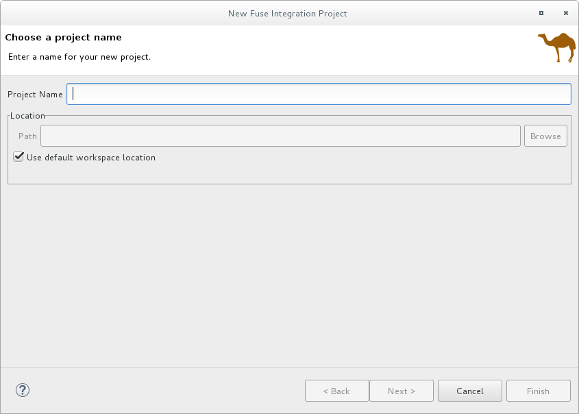
Select New → Project → Red Hat Fuse → Fuse Integration Project to open the New Fuse Integration Project wizard.
The wizard opens with the Use default workspace location option selected in the Location pane.
-
In Project Name, type a name for the new project, for example
MySampleProject. Specify the workspace location in which you want to store the data for the project.
- To use the default workspace, leave the Use default workspace location option enabled.
To use an alternative location clear the Use default workspace location option and specify a location in the Path field.
Click
 to quickly find and select an alternate workspace.
- Click Next to open the Select a Target Environment page.
Configuring the project deployment environment
When you create a new project, you specify the project’s target deployment environment so that your project has the resources it needs at runtime. You must select a deployment platform and a Camel version. Optionally, you can specify a runtime configuration.
With the Select a Target Environment page open:
Select whether you want to deploy the project on Kubernetes/OpenShift or on a Standalone platform.
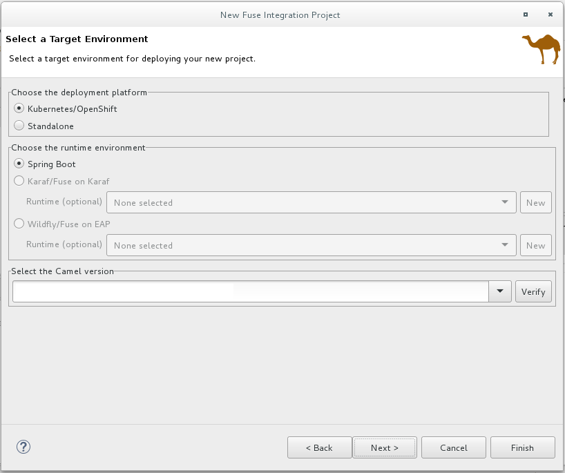
If you select Kubernetes/OpenShift for the deployment platform, the Sprint Boot runtime is automatically selected and you can skip to Step 3.
If you select Standalone for the deployment platform:
Choose a target runtime environment:
- Spring Boot
- Karaf/Fuse on Karaf
- Wildfly/Fuse on EAP
For the Karaf and EAP standalone runtime environments, choose one of the following options for the runtime configuration:
- Accept the None selected option (you can define the runtime configuration later).
- Select an existing runtime configuration from the drop-down menu.
- Create a new runtime configuration as described in the section called “Creating a new target runtime (optional)”.
In the Select the Camel version for your new project pane, accept the default Camel version associated with the runtime or change the default by:
- Selecting a Camel version from the drop-down list. Fuse Tooling supports the listed productized versions.
Typing a different Camel version if you want to experiment with non-productized versions (that are not supported).
You can click the Verify button to check whether the tooling can access the specified version. If not, a notification similar to the following example appears in the Select a Target Runtime page header:
 Note
NoteAfter you create, configure, and save a project, you can change the Camel version. See Chapter 12, Changing the Camel version.
- After you choose a runtime environment and a Camel version on which to base your new Fuse Integration project, click Next to open the wizard’s Advanced Project Setup page and then follow the steps in the section called “Selecting a project template”.
Creating a new target runtime (optional)
For the Karaf and EAP standalone runtime environments, you can optionally create a new runtime configuration from the New Fuse Integration Project wizard.
From the wizard’s the Select a Target Runtime page, click New to open the New server runtime environment page:
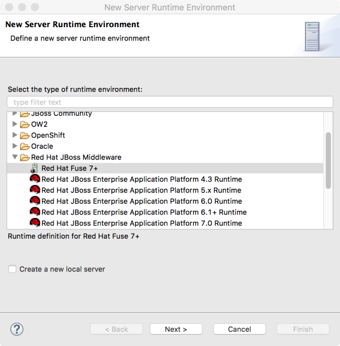
Expand the
Red Hat JBoss Middlewarefolder, and then select a Red Hat Fuse runtime environment.Leave the Create a new local server option unchecked. You can create the local server later when you are ready to publish your project (see Section 28.1, “Adding a Server”).
NoteIf you check the Create a new local server option, the New Fuse Integration Project wizard walks you through additional steps to define and configure the Fuse server runtime (as described in Section 28.1, “Adding a Server”). Then, when it builds the project, it also adds the server runtime to the Servers view in the Fuse Integration perspective.
Click Next to open the server’s New Server Runtime Environment page:
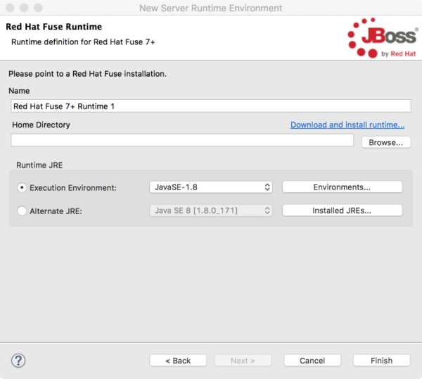
Specify the Name, Home Directory, Execution Environment of the server runtime:
- Name — Accept the default or enter a new name for the runtime environment.
Home Directory — Click the Browse button to locate and select the server runtime’s installation directory.
NoteIf the server is not already installed on your machine, you can install it now by clicking the Download and install runtime link and then following the site’s download instructions. Depending on the site, you might be required to provide valid credentials before you can continue the download process.
Runtime JRE: Execution Environment — Accept the default or select another JavaSE version from the drop-down list.
If the version that you want does not appear on the list, click the Environments button and select the version from that list. The JRE version that you select must be installed on your machine.
NoteFuse 7.x requires JRE version 1.8.
- Runtime JRE: Alternate JRE - If your project requires a different version of Java, you can use this option.
Click Finish to return to the New Fuse Integration Project wizard’s Select a Target Runtme page:
The newly configured target runtime appears in the Target Runtime pane’s drop-down menu, and the Camel version supported by the runtime appears in the Camel Version pane, grayed out.
After you create a Fuse Integration project, it is possible to change the Camel version. See Chapter 12, Changing the Camel version.
- Click Next to specify a template for the project as described in the section called “Selecting a project template”.
Selecting a project template
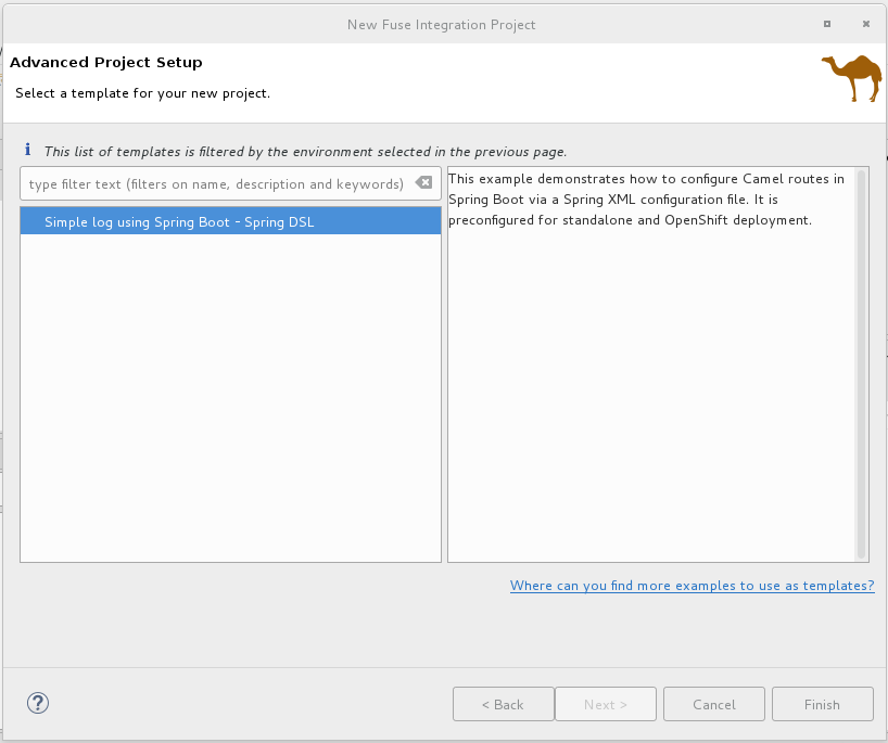
The Advanced Project Setup page provides a list of templates that you can use as a starting point for your new project. The templates, based on common use cases, provide sample code and data to get you started quickly. The list of available templates depends on the runtime environment that you selected on the previous page. Select a template to view its description in the right pane.
If you do not see a template that meets your requirements, you can click the Where can I find more examples to use as templates? link to open an information dialog with a list of URLs with more examples:
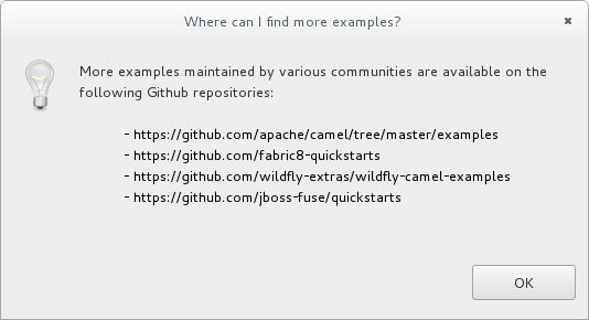
To use one of these examples:
- Select Cancel to exit the New Fuse Integration Project wizard.
- Clone the repository from one of the listed URLs.
- Import the example project into CodeReady Studio as described in Chapter 13, Importing an existing Maven project.
For Fuse on OpenShift there is a single template that demonstrates how to configure Camel routes in Spring Boot using a Spring XML configuration file. This template creates a Fuse Integration project and requires a Camel version newer than 2.18.1.redhat-000012.
This template creates a project that runs on OpenShift servers, and it supports the Spring DSL only. For details on using this template, see Chapter 7, Getting Started with Fuse on OpenShift.
For Wildfly or Fuse on EAP there is a single template that provides a sample Camel route that calls into a bean service to say "Hello". This template creates a project that runs on Red Hat EAP servers, and it supports the Spring DSL only.
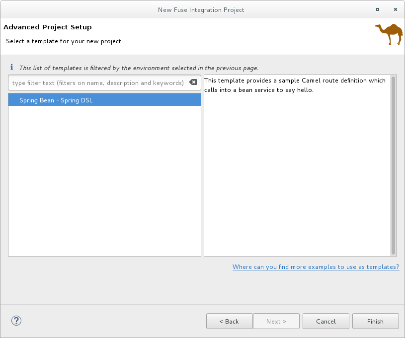
For Karaf or Fuse on Karaf, you have a choice of templates. You can create an empty project, which creates a skeleton Camel context routing file based on one of the three supported Domain Specific Languages (DSLs), or you can use a predefined template, each of which is based on a common use case. Individual templates might not support all DSL options.
NoteFor Java DSL, the tooling generates a
CamelRoute.javafile that you can edit in the tooling’s Java editor, but it does not generate a graphical diagram representation of it.Content Based Router — Provides a sample Camel route that reads files from a specific location and routes them to different output folders according to message content.
This template creates a project that runs on Red Hat Fuse servers, and it supports all three of the DSLs.
CXF code first — Provides a sample Camel route that is started by a CXF web service call.
This template creates a project that runs on Red Hat Fuse servers, and it supports the Spring and Java DSLs only.

- Select a template from the list.
Click Finish.
The tooling starts building the project and adds it to the Project Explorer view.
If the Fuse Integration perspective is not already open, the tooling asks whether you want to switch to it now:

Click Yes to open the new project in the Fuse Integration perspective:
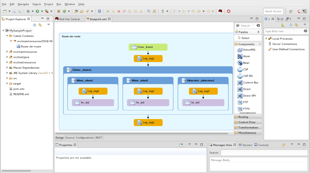
The project appears in the Project Explorer view. By default, the project includes an Apache Camel context (XML) file.
Click the Source tab at the bottom of the canvas to see the generated Camel context file:
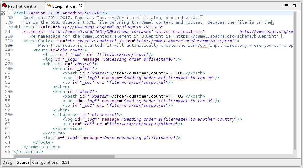
If you want to add another new Camel context file to the project, see Chapter 11, Creating a New Camel XML file.
When you build a project that uses CXF you might want the build process to automatically operate on the Java files to generate WSDL files. To do this, configure the java2ws Maven plug-in in the project’s .pom file. See: Apache CXF Development Guide, Maven Tooling Reference, java2ws.
Resolving Maven dependency errors
You might encounter Maven dependency errors after you create a new Fuse Integration project.
Though it can happen at other times, it more typically occurs when you cancel a project build before the process has finished. Interrupting the process in this way often prevents all of the project’s dependencies from downloading from the Maven repositories, which can take some time.
You can often resolve these dependency errors by updating Maven dependencies as follows:
- In the Project Explorer view, right-click the root project to open the context menu.
- Select Maven → Update Project.
In the Update Maven Project wizard:
- Select the project that you want to update, if more than one appears in the wizard’s list.
- Click the Force Update of Snapshots/Releases option to enable it.
Click OK.
In the bottom, right corner of the workbench, you can view the progress status bar churning as missing dependencies are downloaded from the Maven repositories.
Chapter 2. Editing a routing context in the route editor
The following sections describe how to edit a routing context.
2.1. Adding patterns to a route
Routes consist of a sequence of connected patterns, referred to as nodes once they are placed on the canvas inside a Route container node. A complete route typically consists of a starting endpoint, a string of processing nodes, and one or more destination endpoints.
When you add a pattern into a Route container on the canvas, the pattern takes on a color that indicates its type of node:
-
Blue — Route containers, which correspond to route elements in the context file, and other container nodes, such as
whenandotherwiseEIPs that contain other EIPs that complete their logic - Green — Consumer endpoints that input data entering routes
- Orange — EIPs that route, transform, process, or control the flow of data transiting routes
- Purple — Producer endpoints that output the data exiting routes
Procedure
To add a pattern to a route:
- In the Palette, locate the pattern that you want to add to the route.
Use one of the following methods:
- Click the pattern in the Palette and then, in the canvas, click the route container.
Drag the pattern over the target
Routecontainer and drop it.Alternatively, you can add a pattern on an existing node that has no outgoing connection, or on a connection existing between two nodes, to have the tooling automatically wire the connections between all nodes involved.
The tooling checks whether the resulting connection is valid and then either allows or prevents you from adding the pattern on the target. For valid connections, the tooling behaves differently depending on whether the target is a node or a connection:
- For an existing node, the tooling adds the new node to the target node’s outgoing side (beneath or to the right of it depending on how the editor preferences are set) and automatically wires the connection between them
- For an existing connection, the tooling inserts the new node between the two connected nodes and automatically rewires the connections between the three nodes
Optionally, you can manually connect two nodes:
-
In the
Routecontainer on the canvas, select the source node to display its connector arrow. Drag the source node’s connector arrow (
 ) to the target node, and release the mouse button to drop the connector on it.
Note
) to the target node, and release the mouse button to drop the connector on it.
NoteNot all nodes can be connected. When you try to connect a source node to an invalid target node, the tooling displays the
 symbol attached to the mouse cursor, and the connector fails to stick to the target node.
-
In the
After you add a pattern inside a Route container, you can drag it to different location inside the route container or to another route container on the canvas, as long as it can establish a valid connection. You can also relocate existing nodes that are already connected, as long as the move can establish another valid connection.
To view a short video that illustrates how to reposition endpoints, click here.
- Select File → Save. The tooling saves routes in the context file regardless of whether they are complete.
The new pattern appears on the canvas in the Route container and becomes the selected node. The Properties view displays a list of the new node’s properties that you can edit.
Changing the layout direction
When you connect one node to another, the tooling updates the layout according to the route editor’s layout preference. The default is Down.
To access the route editor 's layout preference:
- On Linux and Windows machines, select Windows → Preferences → Fuse Tooling → Editor → Choose the layout direction for the diagram editor.
- On OS X, select CodeReady Studio → Preferences → Fuse Tooling → Editor → Choose the layout direction for the diagram editor.
2.2. Configuring a pattern
Overview
Most patterns require some explicit configuration. For example, an endpoint requires an explicitly entered URI.
The tooling’s Properties view provides a form that lists all of the configuration details a particular pattern supports. The Properties view also provides the following convenience features:
- validating that all required properties have values
- validating that supplied values are the correct data type for the property
- drop-down lists for properties that have a fixed set of values
- drop-down lists that are populated with the available bean references from the Apache Camel Spring configuration
Procedure
To configure a pattern:
On the canvas, select the node you want to configure.
The Properties view lists all of the selected node’s properties for you to edit. For EIPs, the Details tab lists all of a pattern’s properties. For components from the Components drawer, the Details tab lists the general properties and those that require a value, and the Advanced tab lists additional properties grouped according to function.
The Documentation tab describes the pattern and each of its properties.
- Edit the fields in the Properties view to configure the node.
- When done, save your work by selecting File → Save from the menu bar.
2.3. Removing patterns from a route
Overview
As you develop and update a route, you may need to remove one or more of the route’s nodes. The node’s
![]() icon makes this easy to do. When you delete a node from the canvas, all of its connections with other nodes in the route are also deleted, and the node is removed from the corresponding route element in the context file.
icon makes this easy to do. When you delete a node from the canvas, all of its connections with other nodes in the route are also deleted, and the node is removed from the corresponding route element in the context file.
You can also remove a node by opening its context menu and selecting Remove.
Procedure
To remove a node from a route:
- Select the node you want to delete.
-
Click its
 icon.
icon.
- Click Yes when asked if you are sure you want to delete this element.
The node and all of its connections are deleted from the canvas, and the node is removed from its corresponding route element in the context file.
2.4. Adding routes to the routing context
Overview
The camelContext element within an XML context file creates a routing context. The camelContext element can contain one or more routes, and each route, displayed on the canvas as a Route container node, maps to a route element in the generated camelContext element.
Procedure
To add another route to the camelContext:
In the Design tab, do one of the following:
-
Click a
Routepattern in the Palette's Routing drawer and then click in the canvas where you want to place the route. Drag a
Routepattern from the Palette's Routing drawer and drop it onto the canvas.The Properties view displays a list of the new route’s properties that you can edit.
-
Click a
In the Properties view, enter:
An ID (for example, Route2) for the new route in the route’s Id field
NoteThe tooling automatically assigns an ID to EIP and component patterns dropped on the canvas. You can replace these autogenerated IDs with your own to distinguish the routes in your project.
- A description of the route in the Description field
- Values for any other properties, as needed. Required properties are indicated by an asterisk (*).
- On the menu bar, select File → Save to save the changes you made to the routing context file.
To switch between multiple routes, select the route that you want to display on the canvas by clicking its entry under the project’s
Camel Contextsfolder in the Project Explorer view.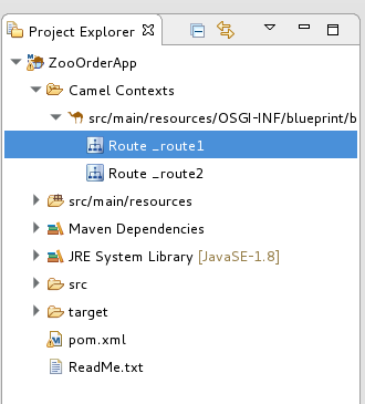
- To display all routes in the context, as space allows, click the context file entry in the Project Explorer view.
To view the code generated by the tooling when you add a route to the canvas, click the Source tab.
NoteYou can alternately add a route in the Source tab, by adding a <route/> element to the existing list within the camelContext element.
2.5. Deleting a route
Overview
In some cases you made need to delete an entire route from your routing context. The Route container’s
![]() icon makes this easy to do. When you delete a route, all of the nodes inside the Route container are also deleted, and the corresponding route element in the context file is removed.
icon makes this easy to do. When you delete a route, all of the nodes inside the Route container are also deleted, and the corresponding route element in the context file is removed.
You can also remove a route using the Route container’s context menu and selecting Remove.
You cannot undo this operation.
Procedure
To delete a route:
If the routing context contains more than one route, first select the route you want to delete in the Project Explorer view.

On the canvas, click the Route container’s
 icon.
icon.
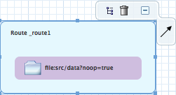
- Click Yes when asked if you are sure you want to delete this element.
The route is removed from the canvas, from the context file, and from the Project Explorer view.
2.6. Adding global endpoints, data formats, or beans
Overview
Some routes rely on shared configuration provided by global endpoints, global data formats, or global beans. You can add global elements to the project’s routing context file by using the route editor’s Configurations tab.
To add global elements to your routing context file:
- Open your routing context file in the route editor.
At the bottom of the route editor, click the Configurations tab to display global configurations, if there are any.

Click Add to open the Create a new global element dialog.
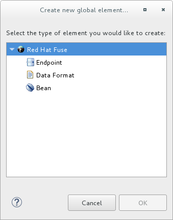
The options are:
- Endpoint — see the section called “Adding a global endpoint”.
- Data Format — see the section called “Adding a global data format”.
- Bean — see the section called “Adding a global bean”.
Adding a global endpoint
In the Create a new global element dialog, select Endpoint and click OK to open the Select component dialog.
 Note
NoteBy default, the Select component dialog opens with the Show only palette components option enabled. To see all available components, uncheck this option.
NoteThe Grouped by categories option groups components by type.
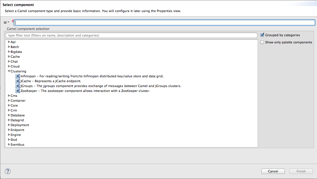
In the Select component dialog, scroll through the list of Camel components to find and select the component you want to add to the context file, and then enter an ID for it in the Id field.
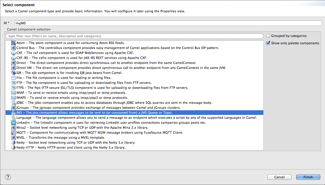
In this example, the JMS component is selected and
myJMSis the Id value.Click Finish.

You can now set properties in the Properties view as needed.
The tooling autofills Id with the value you entered in the component’s
Idfield in [globalEndptSelect]. In this example, Camel builds theuri(required field) starting with the component’s schema (in this case,jms:), but you must specify the destinationName and the destinationType to complete the component’s uri.NoteFor the JMS component, the destination type defaults to
queue. This default value does not appear in theurifield on the Details page until you have entered a value in Destination Name (required field).- To complete the component’s uri, click Advanced.
In the Destination Name field, enter the name of the destination endpoint (for example,
FOO.BAR). In the Destination Type field, enter the endpoint destination’s type (for example,queue,topic,temp:queue, ortemp:topic).
The Properties view’s Details and Advanced tabs provide access to all properties available for configuring a particular component.
Click the Consumer (advanced) tab.

Enable the properties Eager Loading Of Properties and Expose Listener Session.
In the route editor, switch to the Source tab to see the code that the tooling added to the context file (in this example, a configured JMS endpoint), before the first route element.

- When done, save your changes by selecting File → Save on the menu bar.
Adding a global data format
In the Create a new global element dialog, select Data Format and click OK to open the Create a global Data Format dialog.
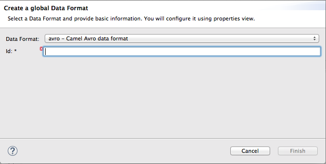
The data format defaults to
avro, the format at the top of the list of those available.-
Open the Data Format drop-down menu, and select the format you want, for example,
xmljson. In the Id field, enter a name for the format, for example, myDataFormat).
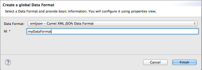
Click Finish.

In the Properties view, set property values as appropriate for your project, for example:

In the route editor, click the Source tab to see the code that the tooling added to the context file. In this example, a configured xmljson data format is before the first route element.
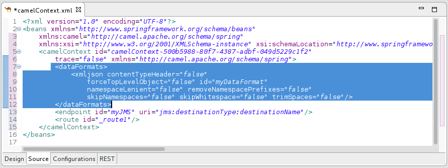
- When done, save your changes by selecting File → Save on the menu bar.
Adding a global bean
A global bean enables out-of-route bean definitions that can be referenced from anywhere in the route. When you copy a Bean component from the palette to the route, you can find defined global beans in the Properties view’s Ref dropdown. Select the global bean that you want the Bean component to reference.
To add a global bean element:
In the Create a new global element window, select Bean and click OK to open the Bean Definition dialog.
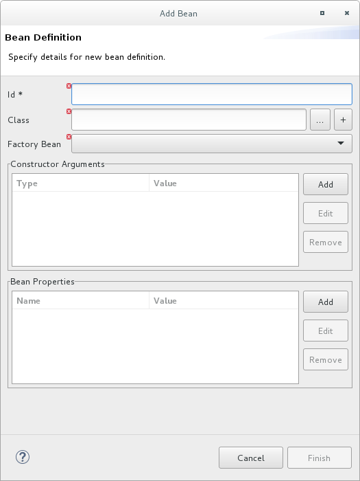
- In the Id field, enter an ID for the global bean, for example, TransformBean. The ID must be unique in the configuration.
Identify a bean class or a factory bean.
To specify a factory bean, you must have already added another global bean with a factory class specified. You can then select that global bean to declare it as a global bean factory. One instance of the bean factory class will be in the runtime. Other global beans can call factory methods on that class to create their own instances of other classes.
To fill the Class field, do one of the following:
- Enter the name of a class that is in the project or in a referenced project.
- Click … to navigate to and select a class that is in the project or in a referenced project.
- Click + to define a new bean class and add it as a global bean.
If the bean you are adding requires one or more arguments, in the Constructor Arguments section, for each argument:
- Click Add.
-
Optionally, in the Type field, enter the type of the argument. The default is
java.lang.String. - In the Value field, enter the value of the argument.
- Click OK.
Optionally specify one or more properties that are accessible to the global bean. In the Bean Properties section, do the following for each property:
- Click Add.
- In the Name field, enter the name of the property.
- In the Value field, enter the value of the property.
- Click OK.
Click Finish to add the global bean to the configuration. The global bean ID you specified appears in the Configurations tab, for example:
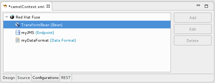
Switch to the Source tab to see the
beanelement that the tooling added to the context file. For example:
Click the Configurations tab to return to the list of global elements and select a global bean to display its standard properties in the Properties view, for example:
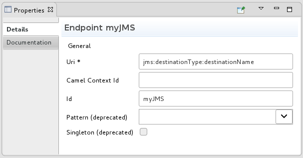 Note
NoteTo view or edit a property that you specified when you added a global bean, select the bean in the Configurations tab and then click Edit.
Set global bean properties as needed:
-
Depends-on is a string that you can use to identify a bean that must be created before this global bean. Specify the ID (name) of the depended on bean. For example, if you are adding the
TransformBeanand you set Depends-on toChangeCaseBeanthenChangeCaseBeanmust be created and thenTransformBeancan be created. When the beans are being destroyed thenTransformBeanis destroyed first. - Factory-method is useful only when the global bean is a factory class. In this situation, specify or select a static factory method to be called when the bean is referenced.
-
Scope is
singletonorprototype. The default,singleton, indicates that Camel uses the same instance of the bean each time the bean is called. Specifyprototypewhen you want Camel to create a new instance of the bean each time the bean is called. -
Init-method lets you specify or select which of the bean’s
init()methods to call when the bean is referenced. - Destroy-method lets you specify or select which of the bean’s destory methods to call when the processing performed by the bean is done.
-
Depends-on is a string that you can use to identify a bean that must be created before this global bean. Specify the ID (name) of the depended on bean. For example, if you are adding the
- When done, save your changes by selecting File → Save on the menu bar.
Deleting a global element
The procedure is the same whether removing an endpoint, data format or bean that was previously added to the routing context.
You cannot perform an undo operation for deletion of a global element. If you inadvertently delete a global element that you want to keep in the configuration you might be able to undo the deletion by closing the context file without saving it. If this is not feasible then re-add the inadvertently deleted global element.
In the Configurations tab, select the global element that you want to delete.
For example, suppose you want to delete the data format
myDataFormatthat was added in the section called “Adding a global data format”: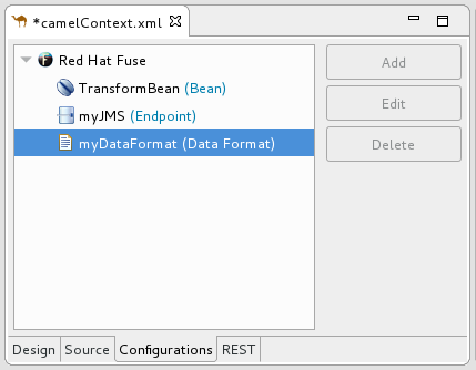
Click Delete.
The global element
myDataFormatdisappears from the Configurations tab.Switch to the Source tab to check that the tooling removed the XML code from the routing context.

- When done, save your changes by selecting File → Save on the menu bar.
Editing a global element
The procedure is the same whether modifying the properties of an endpoint, data format or bean that you added to the routing context.
Typically, you do not want to change the ID of a global element. If the global element is already in use in a running route, changing the ID can break references to the global element.
In the Configurations tab, select the global element that you want to edit.
For example, to edit the endpoint
myJMSthat was added in the section called “Adding a global endpoint”, select it: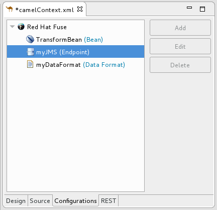
Click Edit.
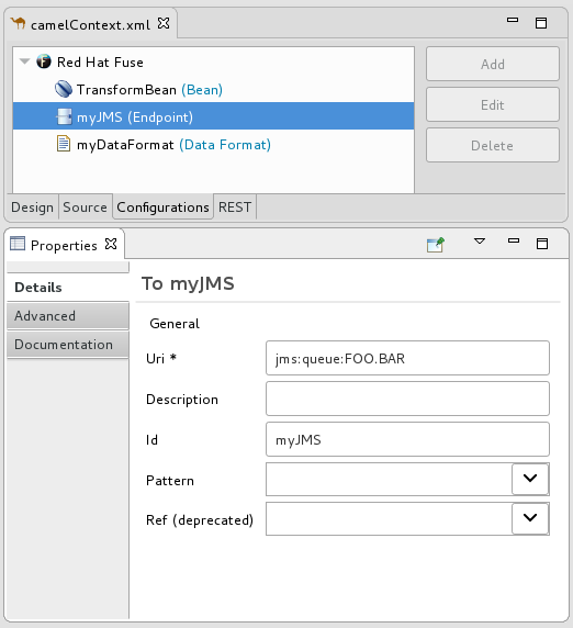
In the Properties view, modify the element’s properties as needed.
For example, open the Advanced → Consumer tab, and change the value of Concurrent Consumers to
2: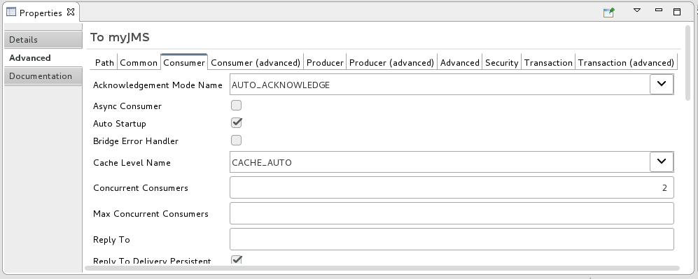
In the route editor, click the Source tab and check that the tooling added the property
concurrentConsumers=2to the routing context: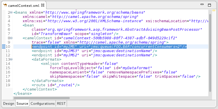
- When done, save your changes by selecting File → Save on the menu bar.
2.7. Configuring the route editor
Overview
Using Fuse preference settings, you can specify options for the route editor’s behavior and user interface:
- The default language to use for expressions in Enterprise Integration Patterns (EIPs)
- The direction (to the right or down) in which patterns flow on the Design canvas when you create routes
- Whether the Design canvas displays a grid overlay in the background of the canvas.
- The method for labeling nodes on the Design canvas
Procedure
To configure the route editor:
Open the Editor preferences window:
- On Linux and Windows machines, select Windows → Preferences → Fuse Tooling → Editor.
On OS X, select CodeReady Studio → Preferences → Fuse Tooling → Editor.

- To select the default language that you want to use for expressions in Enterprise Integration Pattern (EIP) components, select a language from the drop-down list. The default is Simple.
- To specify the direction in which you want the route editor to align the patterns in a route, select Down or Right. The default is Down.
- To enable or disable displaying a grid overlay on the background of the canvas, check the box next to Show diagram grid in Routes Editor. The default is enabled.
To enable or disable using component IDs as labels in the route editor’s Design tab, check the box next to Use ID values for component labels. The default is disabled.
If you check this option and also specify a preferred label for a component (see Step 6), then the preferred label is used for that component instead of the ID value.
To use a parameter as the label for a component (except for endpoints, such as File nodes) in the route editor’s Design tab:
In the Preferred labels section, click Add. The New Preferred Label dialog opens.
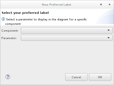
- Select a Component and then select the Parameter to use as the label for the component.
Click OK. The component and parameter pairs are listed in the Editor Preferences window.

You can optionally Edit and Remove component labels.
NoteIf you check the Use ID values for component labels option, it applies to all components except for the components listed in the Preferred labels section.
- Click Apply and Close to apply the changes to the Editor preferences and close the Preferences window.
You can restore the route editor’s original defaults at any time by returning to the Editor preferences dialog and clicking Restore Defaults.
Chapter 3. Viewing and editing Rest DSL components
Apache Camel supports multiple approaches to defining REST services. In particular, Apache Camel provides the REST DSL (Domain Specific Language), which is a simple but powerful API that can be layered over any REST component and provides integration with the OpenAPI 2.0 specification. OpenAPI (formerly Swagger) is a vendor-neutral and portable open description format for API services.
For information about using the Camel Rest DSL, see the “Defining REST services” chapter of the Apache Camel Development Guide.
With the Fuse Tooling, you can view and edit Rest DSL components that are in your Camel Context file.
You can also configure your Fuse Integration project to expose your REST API to an OpenAPI client as described here: https://access.redhat.com/articles/4296981.
3.1. Viewing a graphical representation of Rest DSL components
To view the REST DSL components in your Camel Context file in graphical mode:
- Open the Camel Context file in the route editor.
Click the REST tab to the view the Rest DSL components.
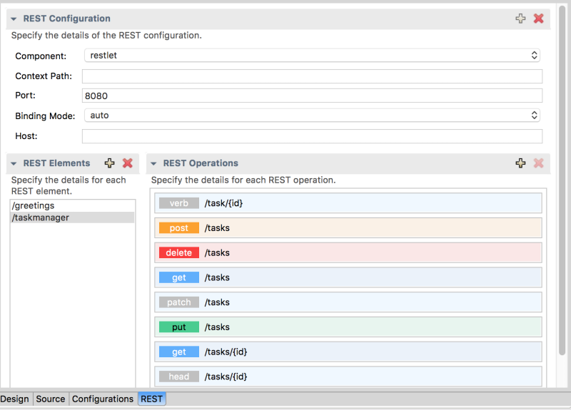
The REST Configuration section displays these configuration options:
- Component — The Camel component to use for the REST transport.
- Context Path — The leading context-path for the REST services. You can use this option for components, such as Servlet, where the web application is deployed using a context-path.
- Port — The port number that exposes the REST service.
- Binding Mode — The binding mode for JSON or XML format messages. Possible values are: off (the default), auto, json, xml, or json_xml.
- Host — The hostname to use for exposing the REST service.
-
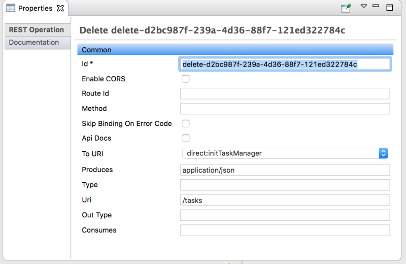
Click a REST element to view its associated operations (for example,
GET,POST,PUT, andDELETE) in the REST Operations section. Click a REST element or a REST operation to view its properties in the Properties view.
3.2. Editing Rest DSL components in the graphical view
You can add, edit, or delete REST elements in your project’s Camel Context file in the REST tab.
To add a new REST element:
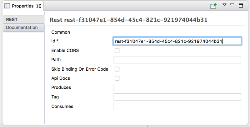
- In the REST elements section, click the + button. A REST element is added to the list of REST elements.
In the Properties view, edit the REST element properties.
To add a REST operation to a REST element:
- In the list of REST elements, select a REST element.
In the REST operations section, click the + button.
The Add REST Operation dialog box opens.
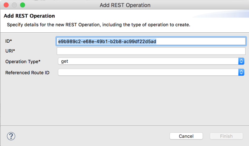
- Specify the ID, URI, and Operation Type. Optionally, select a Referenced Route ID.
- Click Finish. The new operation shows in the list of REST operations for the selected REST element.
- To edit a REST element or operation, select it in the REST tab and then edit its property values in the Properties tab.
- To remove a selected REST element or operation, click the x button.
3.3. Viewing and editing the Rest DSL source code
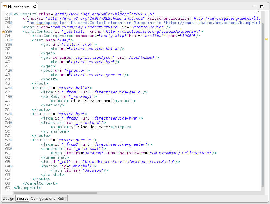
You can also view and edit Rest DSL components in the Source tab:
- Open the Camel Context file in the route editor.
Click the route editor’s Source tab and then edit the code.
- Optionally, click the REST tab to see the changes in the graphical view.
- To save your changes, select File → Save.
Chapter 4. Migrating a SOAP application to RESTful web services
You can use the WSDL-to-Camel Rest wizard to migrate from an existing JAX-WS SOAP web services implementation to a RESTful web services implementation by using an existing WSDL. The wizard is available as part of Fuse Tooling and it is based on the wsdl2rest utility, available in Github wsdl2rest project.
It supports the following specifications/configurations:
- Document/literal (doc/lit)
- Document/literal Wrapped (doc/lit wrap)
- RPC/literal (rpclit)
4.1. Wizard workflow
The wizard uses a WSDL path which can be a valid URL (in the file:// URL form) or a remote URL (using http or https) and the selected Fuse project. In the wizard, you provide the paths for the generated Java code, the generated Camel configuration file, the target address for the generated camel endpoint, and the bean implementation class.
The wizard generates the destination Java and Camel paths based on the project. The generated Java code is available in src/main/java and the Camel file in an appropriate location for Spring or Blueprint, such as src/main/resources/META-INF/spring.
You can modify the generated classes and configure them to a certain point.
4.2. Prerequisites
Before you begin, you must meet these prerequisites:
- A pre-existing Fuse Integration Project. You can create a new project using the File→ New→ Fuse Integration Project wizard.
-
A WSDL file accessible through URL. It can be local (
file:// url) or remote (httporhttps).
4.3. Migrating a sample SOAP application to RESTful web services
Follow these steps to run the wizard:
- In CodeReady Studio, select your Fuse project in the Project Explorer view.
Right-click on the Fuse project and then select New → Camel Rest DSL from WSDL.
The Select Incoming WSDL and Project for Generated Output page opens. The Destination Project field is automatically pre-populated with the Fuse project selected in the Project Explorer. This project is the destination for the artifacts that the wizard generates.
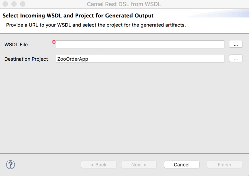
- For WSDL File, specify the original SOAP service for processing.
Click Next. The Specify Advanced Options for WSDL-to-REST Processing page appears.
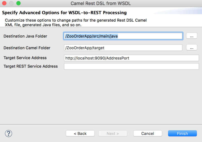
- For Destination Java Folder, specify the location of the CXF-generated Java classes.
For Destination Camel Folder, specify the location of the generated Camel Rest DSL configuration file.
NoteThe path and name of the generated Camel file varies based on the type of Camel project:
-
For Spring projects:
src/main/resources/META-INF/rest-camel-context.xml -
For Spring Boot projects:
src/main/resources/spring/rest-springboot-context.xml -
For Blueprint projects:
src/main/resources/OSGI-INF/rest-blueprint-context.xml
-
For Spring projects:
- Optionally, for Target Service Address provide the SOAP address specified in the WSDL binding. You can change this option to match the actual address of the SOAP service referenced by the WSDL.
-
Optionally, for Target REST Service Address provide the URL for accessing the REST service. This URL is decomposed into settings for the
<restConfiguration>and<rest>tags in the Rest DSL to specify the complete URL for REST operations mapped to the SOAP service.
Click Finish to create two files as the output:
- The Camel configuration with Rest DSL.
- Java classes from CXF to wrap the SOAP service.
Chapter 5. Creating a new Apache Camel JUnit test case
Overview
A common way of testing routes is to use JUnit. The design time tooling includes a wizard that simplifies creating a JUnit test case for your routes. The wizard uses the endpoints you specify to generate the starting point code and configuration for the test.
After you create the boilerplate JUnit test case, you need to modify it to add expectations and assertions specific to the route that you’ve created or modified, so the test is valid for the route.
Prerequisites
Before you create a new JUnit test case, you need to perform a preliminary task:
- If you are replacing an existing JUnit test case, you need to delete it before you create a new one. See the section called “Deleting and existing JUnit test case”.
-
If you are creating a new JUnit test case in a project that hasn’t one, you need to first create the project_root
/src/test/javafolder for the test case that is included in the build path. See the section called “Creating and adding thesrc/test/javafolder to the build path”.
Deleting and existing JUnit test case
-
In the Project Explorer view, expand the project’s root node to expose the <root_project>
/src/test/javafolder. Locate the JUnit test case file in the
/src/test/javafolder.Depending on which DSL the project is based on, the JUnit test case file is named
BlueprintXmlTest.javaorCamelContextXmlTest.java.Right-click the JUnit test case
.javafile to open the context menu, and then select Delete.The JUnit test case
.javafile disappears from the Project Explorer view.You can now create a new JUnit test case.
Creating and adding the src/test/java folder to the build path
- In the Project Explorer view, right-click the project’s root to open the context menu.
- Select New → Folder to open the Create a new folder resource wizard.
In the wizard’s project tree pane, expand the project’s root node and select the
srcfolder.Make sure <project_root>
/srcappears in the Enter or select the parent folder field.-
In Folder name, enter
/test/java. This folder will store the new JUnit test case you create. Click Finish.
In the Project Explorer view, the new
src/test/javafolder appears under thesrc/main/resourcesfolder. You can verify that this folder is on the class path by opening its context menu and selecting Build Path. If Remove from Build Path is a menu option, you know thesrc/test/javafolder is on the class path.You can now create a new JUnit test case.
Creating a JUnit test case
To create a new JUnit test case for your route:
-
In the Project Explorer view, select the routing context
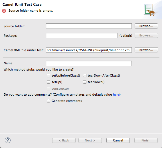
.xmlfile in your project. Right-click it to open the context menu, and then select New → Camel Test Case to open the New Camel JUnit Test Case wizard, as shown in Figure 5.1, “New Camel JUnit Test Case wizard”.
Figure 5.1. New Camel JUnit Test Case wizard
Alternatively, you can open the wizard by selecting File → New → Other > Fuse > Camel Test Case from the menu bar.
In Source folder, accept the default location of the source code for the test case, or enter another location.
You can click
 to search for a location.
In Package, accept the default package name for the generated test code, or enter another package name.
You can click
 to search for a package.
In Camel XML file under test, accept the default pathname of the routing context file that contains the route you want to test, or enter another pathname.
You can click
 to search for a context file.
- In Name, accept the default name for the generated test class, or enter another name.
- Select the method stubs you want to include in the generated code.
- If you want to include the default generated comments in the generated code, check the Generate comments box.
Click
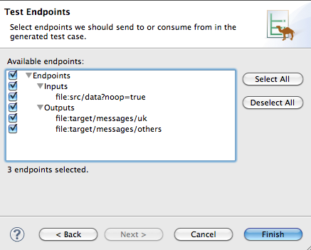
 to open the Test Endpoints page. For example, Figure 5.2, “New Camel JUnit Test Case page” shows a route’s input and output file endpoints selected.
Figure 5.2. New Camel JUnit Test Case page
- Under Available endpoints, select the endpoints you want to test. Click the checkbox next to any selected endpoint to deselect it.
Click
 .
Note
.
NoteIf prompted, add JUnit to the build path.
The artifacts for the test are added to your project and appear in the Project Explorer view under src/test/java. The class implementing the test case opens in the Java editor.
Chapter 6. Running routes inside Red Hat Fuse Tooling
There are two ways to run your routes using the tooling:
6.1. Running routes as a local Camel context
Overview
The simplest way to run an Apache Camel route is as a Local Camel Context. This method enables you to launch the route directly from the Project Explorer view’s context menu. When you run a route from the context menu, the tooling automatically creates a runtime profile for you. You can also create a custom runtime profile for running your route.
Your route runs as if it were invoked directly from the command line and uses Apache Camel’s embedded Spring container. You can configure a number of the runtime parameters by editing the runtime profile.
Procedure
To run a route as a local Camel context:
- In the Project Explorer view, select a routing context file.
Right-click it to open the context menu, and then select Run As → Local Camel Context.
NoteSelecting Local Camel Context (without tests) directs the tooling to run the project without performing validation tests, which may be faster.
Result
The Console view displays the output generated from running the route.
6.2. Running routes using Maven
Overview
If the project containing your route is a Maven project, you can use the m2e plug-in to run your route. Using this option, you can execute any Maven goals, before the route runs.
Procedure
To run a route using Maven:
- In the Project Explorer view, select the root of the project .
Right-click it to open the context menu, and then select Run As → Maven build.
The first time you run the project using Maven, the Edit Configuration and launch editor opens, so you can create a Maven runtime profile.
To create the runtime profile, on the Maven tab:
Make sure the route directory of your Apache Camel project appears in the Base directory: field.
For example, on Linux the root of your project is similar to
~/workspace/simple-router.In the Goals: field, enter
camel:run.ImportantIf you created your project using the Java DSL, enter
exec:javain the Goals: field.- Click Apply and then Run.
- Subsequent Maven runs use this profile, unless you modify it between runs.
Results
The Console view displays the output from the Maven run.
6.3. Working with runtime profiles
Red Hat Fuse Tooling stores information about the runtime environments for each project in runtime profiles. The runtime profiles keep track of such information as which Maven goals to call, the Java runtime environment to use, any system variables that need to be set, and so on. A project can have more than one runtime profile.
6.3.1. Editing a Local Camel Context runtime profile
Overview
A Local Camel Context runtime profile configures how Apache Camel is invoked to execute a route. A Local Camel Context runtime profile stores the name of the context file in which your routes are defined, the name of the main to invoke, the command line options passed into the JVM, the JRE to use, the classpath to use, any environment variables that need to be set, and a few other pieces of information.
The runtime configuration editor for a Local Camel Context runtime profile contains the following tabs:
- Camel Context File — specifies the name of the new configuration and the full path of the routing context file that contains your routes.
- JMX — specifies JMX connection details, including the JMX URI and the user name and password (optional) to use to access it.
- Main — specifies the fully qualified name of the project’s base directory, a few options for locating the base directory, any goals required to execute before running the route, and the version of the Maven runtime to use.
- JRE — specifies the JRE and command line arguments to use when starting the JVM.
- Refresh — specifies how Maven refreshes the project’s resource files after a run terminates.
- Environment — specifies any environment variables that need to be set.
- Common — specifies how the profile is stored and the output displayed.
The first time an Apache Camel route is run as a Local Camel Context, Red Hat Fuse Tooling creates for the routing context file a default runtime profile, which should not require editing.
Accessing the Local Camel Context’s runtime configuration editor
- In the Project Explorer view, select the Camel context file for which you want to edit or create a custom runtime profile.
- Right-click it to open the context menu, and then select Run As → Run Configurations to open the Run Configurations dialog.
-
In the context selection pane, select Local Camel Context, and then click
 at the top, left of the context selection pane.
- In the Name field, enter a new name for your runtime profile.
Figure 6.1. Runtime configuration editor for Local Camel Context
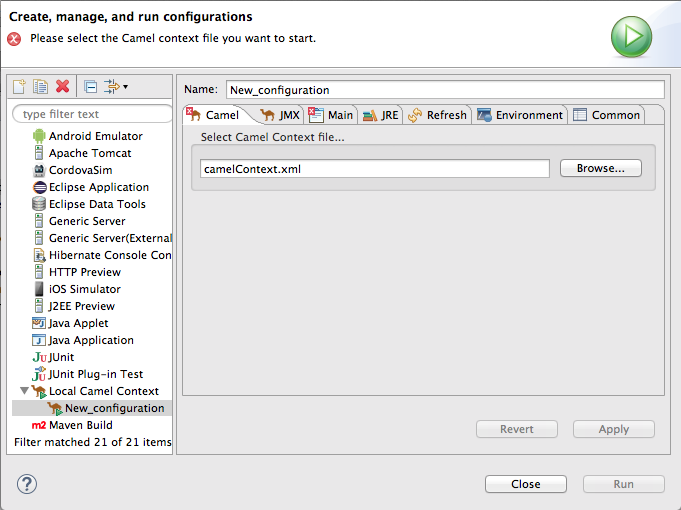
Setting the camel context file
The Camel Context File tab has one field, Select Camel Context file…. Enter the full path to the routing context file that contains your route definitions.
The Browse button accesses the Open Resource dialog, which facilitates locating the target routing context file. This dialog is preconfigured to search for files that contain Apache Camel routes.
Changing the command line options
By default the only command line option passed to the JVM is:
-fa context-fileIf you are using a custom main class you may need to pass in different options. To do so, on the Main tab, click the Add button to enter a parameter’s name and value. You can click the Add Parameter dialog’s Variables… button to display a list of variables that you can select.
To add or modify JVM-specific arguments, edit the VM arguments field on the JRE tab.
Changing where output is sent
By default, the output generated from running the route is sent to the Console view. But you can redirect it to a file instead.
To redirect output to a file:
- Select the Common tab.
In the Standard Input and Output pane, click the checkbox next to the Output File: field, and then enter the path to the file where you want to send the output.
The Workspace, File System, and Variables buttons facilitate building the path to the output file.
6.3.2. Editing a Maven runtime profile
Overview
A Maven runtime profile configures how Maven invokes Apache Camel. A Maven runtime profile stores the Maven goals to execute, any Maven profiles to use, the version of Maven to use, the JRE to use, the classpath to use, any environment variables that need to be set, and a few other pieces of information.
The first time an Apache Camel route is run using Maven, you must create a default runtime profile for it.
The runtime configuration editor for a Fuse runtime profile contains the following tabs:
- Main — specifies the name of the new configuration, the fully qualified name of the project’s base directory, a few options for locating the base directory, any goals required to execute before running the route, and the version of the Maven runtime to use.
- JRE — specifies the JRE and command line arguments to use when starting the JVM.
- Refresh — specifies how Maven refreshes the project’s resource files after a run terminates.
- Source — specifies the location of any additional sources that the project requires.
- Environment — specifies any environment variables that need to be set.
- Common — specifies how the profile is stored and the output displayed.
Accessing the Maven runtime configuration editor
- In the Project Explorer view, select the root of the project for which you want to edit or create a custom runtime profile.
- Right-click it to open the context menu, and then select Run As → Run Configurations to open the Run Configurations dialog.
-
In the context selection pane, select Maven Build, and then click
 at the top, left of the context selection pane.
Figure 6.2. Runtime configuration editor for Maven
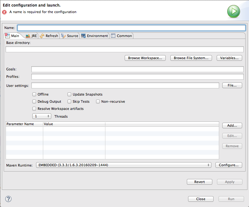
Changing the Maven goal
The most commonly used goal when running a route is camel:run. It loads the routes into a Spring container running in its own JVM.
The Apache Camel plug-in also supports a camel:embedded goal that loads the Spring container into the same JVM used by Maven. The advantage of this is that the routes should bootstrap faster.
Projects based on Java DSL use the exec:java goal.
If your POM contains other goals, you can change the Maven goal used by clicking the Configure… button next to the Maven Runtime field on the Main tab. On the Installations dialog, you edit the Global settings for <selected_runtime> installation field.
Changing the version of Maven
By default, Red Hat Fuse Tooling for Eclipse uses m2e, which is embedded in Eclipse. If you want to use a different version of Maven or have a newer version installed on your development machine, you can select it from the Maven Runtime drop-down menu on the Main tab.
Changing where the output is sent
By default, the output from the route execution is sent to the Console view. But you can redirect it to a file instead.
To redirect output to a file:
- Select the Common tab.
Click the checkbox next to the Output File: field, and then enter the path to the file where you want to send the output.
The Workspace, File System, and Variables buttons facilitate building the path to the output file.
Chapter 7. Getting Started with Fuse on OpenShift
Fuse on OpenShift (the name for Fuse Integration Services since 7.0) enables you to deploy Fuse applications on OpenShift Container Platform.
For Fuse Integration projects (Fuse on OpenShift projects), Fuse Tooling requires installation of the Red Hat Container Development Kit (CDK) v3.x. See the Getting Started Guide for instructions. In addition to the prerequisites specified in this guide, you need to establish a Red Hat account if you do not have one. Your Red Hat user name and password are required to start the virtual OpenShift instance provided in the Red Hat Container Development Kit.
You can easily get an account by registering on the Red Hat Customer Portal. Click
![]() in the upper right corner of the white banner, and then click
in the upper right corner of the white banner, and then click
 on the Login to Your Red Hat Account page.
Fuse Tooling enables you to develop and deploy Fuse Integration projects using the s2i binary workflow. In this workflow, the tooling builds your project locally, assembles it into an image stream, then pushes the image stream to OpenShift, where it is used to build the Docker container. Once the Docker container is built, OpenShift deploys it in a pod.
Fuse Tooling works only with the S2I binary workflow and only with projects based on the Spring Boot framework.
Although Fuse Tooling can deploy Fuse Integration projects created using the tooling to remote OpenShift servers, this chapter describes creating and deploying Fuse Integration projects to a virtual OpenShift instance, installed locally using the Red Hat Container Development Kit (CDK) v3.x.
The following sections describe how to create and deploy your first Fuse Integration project:
- Section 7.1, “Adding the Red Hat Container Development Kit server”
- Section 7.2, “Starting the Container Development Environment (CDE) and virtual OpenShift server”
- Section 7.3, “Creating a new OpenShift project”
- Section 7.4, “Creating a new Fuse Integration project”
- Section 7.5, “Deploying the Fuse Integration project to OpenShift”
You can also run a Fuse Integration project as a local Camel context, see Section 6.1, “Running routes as a local Camel context”, and then connect to it in the JMX Navigator view, where you can monitor and test the routing context. You can also run the Camel debugger on a Fuse Integration project (Part II, “Debugging Routing Contexts”) to expose and fix any logic errors in the routing context.
7.1. Adding the Red Hat Container Development Kit server
To add the Red Hat Container Development Kit to the Servers view:
If necessary, switch to the Fuse Integration perspective by selecting Window → Perspective → Open Perspective → Fuse Integration.
NoteIf a view that is described in this procedure is not open, you can open it by selecting Window → Show View → Other and then select the name of the view that you want to open.
In the Servers view, click the link No servers are available. Click this link to create a new server… to open the Define a New Server wizard. This link appears only when the Servers view contains no server entry.
Otherwise, right-click in the Servers view to open the context menu, and then select New → Server to open the Define a New Server wizard.
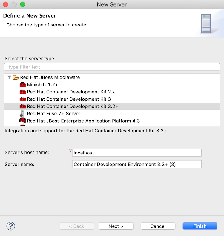
Select Red Hat JBoss Middleware → Red Hat Container Development Kit 3.2+.
Accept the defaults for:
-
Server’s hostname —
localhost -
Server name —
Container Development Environment
-
Server’s hostname —
- Click Next to open the Red Hat Container Development Environment page.
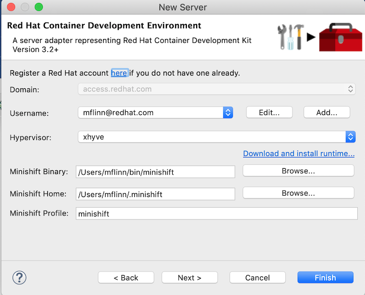
- Next to MiniShift Binary, click Browse, navigate to the location where you installed the Red Hat Container Development Kit 3.x and then click Open.
- Next to Username, click Add to open the Add a Credential page.
Set the credentials this way:
- Username — Enter the name you use to log into your Red Hat account.
- Always prompt for password — Leave as is (disabled).
- Password — Enter the password you use to log into your Red Hat account.
Click OK to return to the Red Hat Container Development Environment page, which is now populated. For example:
- Click Finish. Container Development Environment 3.2+ [Stopped, Synchronized] appears in the Servers view. Container Development Environment 3.2+ is the default server name when you add a CDK 3.x server.
7.2. Starting the Container Development Environment (CDE) and virtual OpenShift server
Starting the Container Development Environment (CDE) also starts the virtual OpenShift server. Stopping the CDE also stops the virtual OpenShift server.
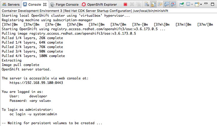
In the Servers view, select Container Development Environment 3 [stopped, Synchronized], and then click
 on the Servers menu bar.
Console view opens and displays the status of the startup process:
 Note
NoteOn initial startup, the CDE asks whether you accept the untrusted SSL certificate. Click Yes.
When the startup process has finished, the Servers view displays:

Switch to the OpenShift Explorer view.
The virtual OpenShift server instance,
developer, is also running:
https://192.168.99.100:8443is an example of a URL for the OpenShift developer web console. Your installation displays the URL for your instance. For more details, see Section 7.6, “Accessing the OpenShift web console”.
7.3. Creating a new OpenShift project
When you deploy your Fuse Integration project to OpenShift, it is published to the OpenShift project you create here.
- In the OpenShift Explorer view, right-click the developer entry, to open the context menu.
- Select New → Project to open the New OpenShift Project wizard.
Set the new project’s properties this way:
In the Project Name field, enter the name for the project’s namespace on the virtual OpenShift server.
Only lower case letters, numbers, and dashes are valid.
- In the Display Name field, enter the name to display on the virtual OpenShift web console’s Overview page.
Leave the Description field as is.
For example:

Click Finish.
The new OpenShift project (in this example, New FIS Test newtest) appears in the OpenShift Explorer tab, under, in this example, developer https://192.168.99.100:8443:
 Note
NoteMyProject myproject is an initial example project included with OpenShift.
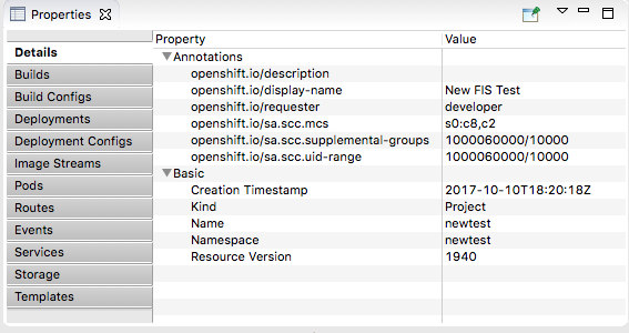
With New FIS Test newtest selected in the OpenShift Explorer view, the Properties view displays the project’s details. For example:
 Note
NoteWhen you deploy the project to OpenShift, the Properties view gathers and displays the same information about the project that the OpenShift web console does.
7.4. Creating a new Fuse Integration project
Before you create a new Fuse Integration project, you should enable staging repositories. This is needed because some Maven artifacts are not in default Maven repositories. To enable staging repositories, select Window → Preferences → Fuse Tooling → Staging Repositories.
To create a Fuse Integration project, use the Spring Boot on OpenShift template:
In the Project Explorer view, right-click to open the context menu and then select New → Fuse Integration Project to open the wizard’s Choose a project name page:

In the Project Name field, type a name that is unique to the workspace you are using, for example, myFISproject.
Accept the defaults for the other options.
Click Next to open the Select a Target Runtime page:

Leave the defaults for Target Runtime (No Runtime selected) and Camel Version.
Click Next to open the Advanced Project Setup page:
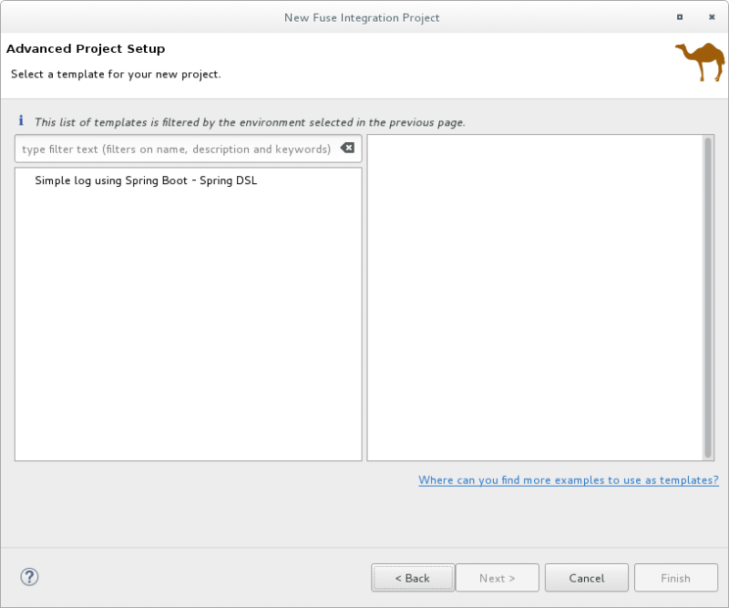
Select the Simple log using Spring Boot - Spring DSL template.
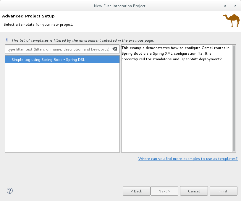
Click Finish.
NoteBecause of the number of dependencies that are downloaded for a first-time Fuse Integration project, building it can take some time.
If the Fuse Integration perspective is not already open, Developer Studio prompts you to indicate whether you want to open it now. Click Yes.
When the build is done the Fuse Integration perspective displays the project, for example:
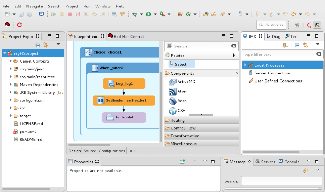
At this point, you can:
- Deploy the project on OpenShift
Section 6.1, “Running routes as a local Camel context” to verify that the routing context runs successfully on your local machine
Connecting to the running context in the JMX Navigator view (see the section called “Viewing processes in a local JMX server”), you can monitor route components and test whether the route performs as expected:
- View a route component’s JMX statistics — see Chapter 21, Viewing a component’s JMX statistics.
- Edit the running route — see Chapter 25, Managing routing endpoints.
- Suspend/resume the running route — see Chapter 27, Managing routing contexts
- Start/stop tracing on the running route — see Chapter 23, Tracing Routes
-
Run the Camel debugger on the project’s
camel-context.xmlfile to discover and fix logic errors — see Part II, “Debugging Routing Contexts”
7.5. Deploying the Fuse Integration project to OpenShift
- In the Project Explorer view, right-click the project’s root (in this example, myFISproject) to open the context menu.
- Select Run As → Run Configurations to open the Run Configurations wizard.
In the sidebar menu, select Maven Build → Deploy <projectname> on OpenShift (in this example, Deploy myFISproject on OpenShift) to open the project’s default run configuration:
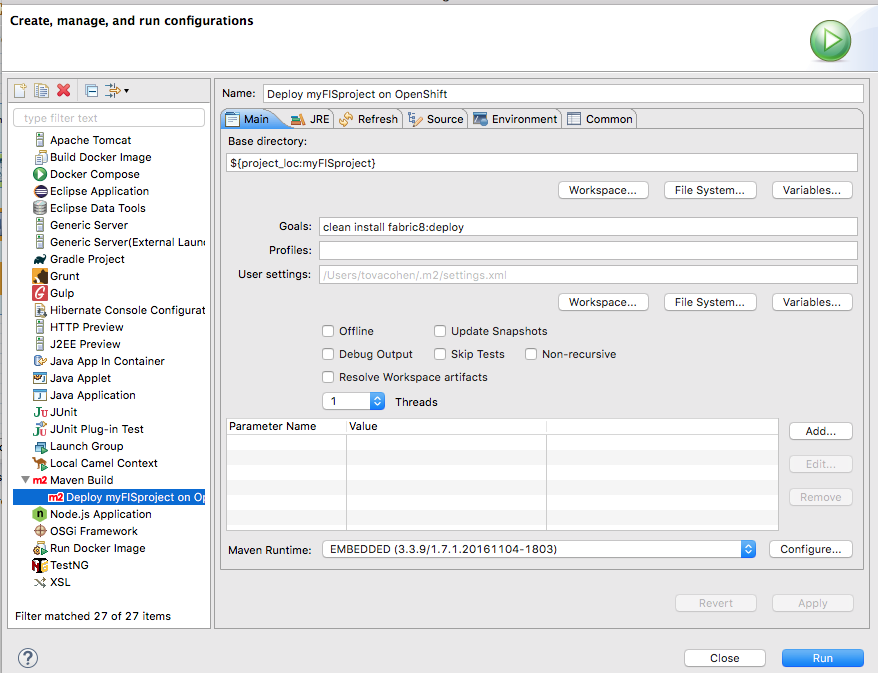
Leave the default settings as they are on the Main tab.
Open the JRE tab to access the VM arguments:
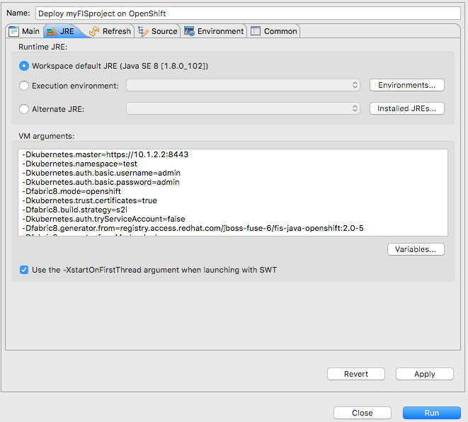
In the VM arguments pane, change the value of the
-Dkubernetes.namespace=testargument to match the project name that you used for the OpenShift project when you created it (OpenShift project name in Section 7.3, “Creating a new OpenShift project”.In this example, change the default value test to newtest:

Depending on your OpenShift configuration, you may need to modify other`VM arguments to support it:
-Dkubernetes.master=https://192.168.99.1:8443When running multiple OpenShift instances or using a remote instance, you need to specify the URL of the OpenShift instance targeted for the deployment. The URL above is an example.
-Dkubernetes.trust.certificates=true-
When using the CDK, this argument is required. Leave it set to
true. -
If you are using an OpenShift instance that has a valid SSL certificate, change the value of this argument to
false.
-
When using the CDK, this argument is required. Leave it set to
Click Apply and then click Run.
Because of the number of dependencies to download, first-time deployment can take some time. The speed of your computer and your internet connection are contributing factors. Typically, it takes 25 to 35 minutes to complete a first-time deployment.
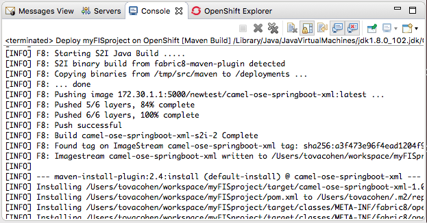
In the Console view, you can track the progress of the deploy process. In the following output, the entry *Pushing image 172.30.1 ….. * indicates that the project built successfully and the application images are being pushed to OpenShift, where they will be used to build the Docker container.
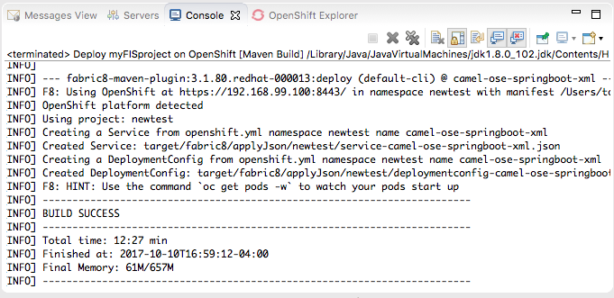
The Console view displays BUILD SUCCESS when deployment completes successfully:
Switch to the OpenShift Explorer view and select New FIS Test newtest:

In the Properties view, the Details page displays all of the project’s property values.

Open the other tabs (Builds, Build Configs, Deployments,…) to view other properties of the project. The Properties view provides the same information as the OpenShift Web Console.
In the OpenShift Explorer view, select
camel-ose-springboot-xmlto view its details in the Properties view: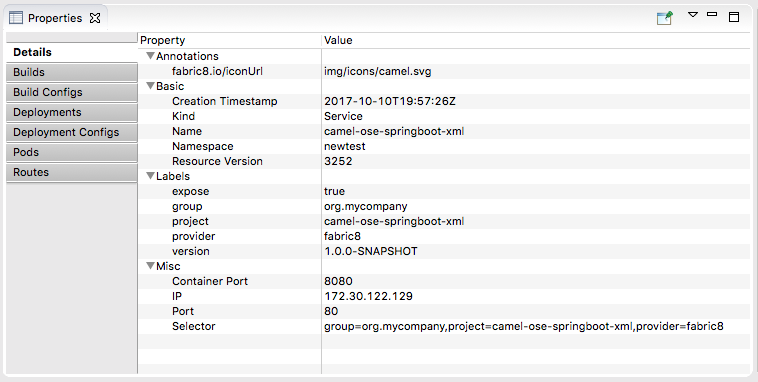
Scroll through the other tabs to view other properties of the deployment configuration.
In the OpenShift Explorer view, select
camel-ose-springboot-xml-1-mdmtd Pod Running, and then view the details of the running instance in the Properties view: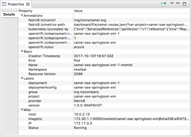
In the OpenShift Explorer view, right-click
camel-ose-springboot-xml-1-mdmtd Pod Running, and then select Pod Logs….NoteIf prompted, enter the path to the installed
ocexecutable. It is required to retrieve pod logs.The Console view automatically opens, displaying the logs from the running pod:

Click
 in the Console view’s menu bar to terminate the session and clear console output.
7.6. Accessing the OpenShift web console
This information applies to Red Hat Container Development Kit installations only.
To access the OpenShift web console, open a browser and enter the OpenShift server’s URL, which is specific to your instance and your machine. For example, enter https://192.168.99.100:8443, in the browser’s address field.
You can log into the web console either as a developer or as an administrator, using the default credentials:
Default developer role
Developer users can view only their own projects and the supplied OpenShift sample project, which demonstrates OpenShift v3 features. Developer users can create, edit and delete any project that they own that is deployed on OpenShift.
-
Username -
developer -
Password -
developer
-
Username -
Default administrator role
An administrator user can view and access all projects on OpenShift (CDK). Administrator users can create, edit and delete, any project deployed on OpenShift.
-
Username -
admin -
Password -
admin
-
Username -
For more information on using the OpenShift web console, see Getting Started Guide.
Chapter 8. Using the Red Hat Fuse SAP Tool Suite
The Red Hat Fuse SAP Tool Suite makes it possible to integrate your Camel routes with a remote SAP Application Server. A variety of SAP components are provided to support Remote Function Calls (RFC) and the sending and receiving of Intermediate Documents (IDocs). The SAP Tool Suite depends on the JCo and IDoc client libraries from SAP. To install and use these libraries, you must have an SAP Service Marketplace Account.
8.1. Installing the Red Hat Fuse SAP Tool Suite
Overview
The Red Hat Fuse SAP Tool Suite provides the Edit SAP Connection Configuration dialog, which helps you to create and manage the SAP Application Server and Destination connections. The suite is not installed by default, because it requires third-party JCo and IDoc client libraries, which are licensed separately by SAP.
Platform restrictions for SAP tooling
Because the SAP tool suite depends on the third-party JCo 3.0 and IDoc 3.0 libraries, it can only be installed on the platforms that these libraries support. For more details about the platform restrictions for SAP tooling, see Red Hat Fuse Supported Configurations.
Prerequisites
Before you can install the Fuse SAP Tool Suite, you must download the JCo and IDoc libraries from the following location:
To download these libraries, you must have an SAP Service Marketplace Account. Be sure to choose the appropriate JCo and IDoc libraries for your operationg system. Also:
- Only version 3.0.11 or greater of the JCo library is supported.
- Only version 3.0.10 or greater of the IDoc library is supported.
For this installation procedure, you can leave the downloaded files in archive format. There is no need to extract the contents.
Procedure
To install the Fuse SAP Tool Suite into Red Hat CodeReady Studio, perform the following steps:
- In Red Hat CodeReady Studio, select File → Import to open the Import wizard.
- In the Select screen of the Import wizard, select Fuse → Install Fuse SAP Tool Suite, and then click Next.
- The Install the Red Hat Fuse SAP Tool Suite screen opens, which displays the instructions for downloading the JCo and IDoc libraries from the SAP Service Marketplace. Click Next.
The Select JCo3 and IDoc3 Archive to Import screen opens. Next to the JCo Archive File field, use the Browse button to select the JCo archive that you downloaded from the SAP Service Marketplace. After selecting the JCo archive, the Archive Version and Archive OS Platform fields are automatically filled in, so that you can check whether the library you are installing has the correct version and OS platform.
Next to the IDoc3 Archive File field, use the Browse button to select the IDoc archive that you downloaded from the SAP Service Marketplace.
After selecting both archive files, click Finish.
A new Install wizard (for installing Eclipse plug-ins) opens automatically. This wizard displays the following to plug-ins to be installed:
- Fuse SAP Tool Suite
SAP JCo3 and IDoc3 Libraries
Make sure that both of these plug-ins are selected. Click Next.
NoteThe
SAP JCo3 and IDoc3 Librariesplug-in is dynamically constructed from the selected JCo and IDoc libraries.
- The Install Details screen allows you to review the plug-ins to be installed. Click Next.
- The Review Licenses dialog opens. Select the I accept radiobutton option, and then click Finish.
- If you encounter a Security Warning dialog (warning of unsigned content), click OK to ignore the warning and continue installing.
- The Restart Eclipse dialog opens. Click OK to restart Eclipse.
8.2. Create and Test SAP Destination Connection
Overview
In Fuse SAP Tool suite, the Edit SAP Connection Configuration dialog helps you to create and manage the SAP Application Destination connections. This section describes how to create and test the SAP destination connection.
Procedure
To create and test an SAP destination connection, perform the following steps:
Navigate to the global Configurations tab of the route editor and click Add.
The Create new global element view appears.
Under SAP, select the type of connection you would like to create. Choose the SAP Connection and click Ok.
The Edit SAP Connection Configuration dialog appears. It allows you to create, edit and delete the Destination and Server Connection Configurations.
To create a new Destination Data Store, click the Add Destination tab.
The Create Destination dialog appears.
- Enter a name for the destination in the Destination Name field and click Ok.
In the Properties dialog,
Click the Basic tab to configure the basic properties required to connect to an SAP destination. In this tab, fill in the following property fields to configure the connection:
- SAP Application Server
- SAP System Number
- SAP Client
- Logon User
- Logon Password
- Logon Language
Click the Connection tab to add values required to connect to an SAP destination. Fill in the following property fields to configure the connection:
- SAP System Number
- SAP Router String
- SAP Application Server
- SAP Message Server
- SAP Message Server Port
- Gateway Host
- Gateway Port
- SAP System ID
- SAP Application Server Group
Click the Authenticate tab to add values required to validate an SAP destination. Fill in the following property fields to configure the connection.
- SAP Authentication type
- SAP Client
- Logon User
- Logon User Alias
- Logon Password
- SAP SSO Logon Ticket
- SAP X509 Login Ticket
- Logon Language
Click the Special tab. In this tab, fill in the following property fields to configure the connection:
- Select CPIC Trace
- Initial Codepage
Click the Pool tab and fill in the following property fields to configure the connection:
- Connection Pool Peak Limit
- Connection Pool Capacity
- Connection Pool Expiration Time
- Connection Pool Expire Check Period
- Connection Pool Max Get Client Time
Click the SNC tab and fill in the following property fields to configure the connection:
- SNC Partner Name
- SNC Level of Security
- SNC Name
- SNC Library Path
Click the Repository tab and fill in the following property fields to configure the connection:
- Repository Destination
- Repository Logon User
Repository Logon Password
NoteIf you need more information about these settings, refer the SAP documentation.
You are now ready to test the destination connection. In the Edit SAP Connection Configuration dialog, right-click on the destination name and select Test.
The Test Destination Connection dialog opens.
The dialog uses the current destination configuration settings to connect to the SAP Destination Data Store. If the test is successful, you will see the following message in the status area:
Connection test for destination 'YourDestination' succeeded.
Otherwise, an error report appears in the status area.
- Click Close to close the Test Destination Connection dialog.
- Click Finish. The newly created SAP Destination Connection appears under SAP.
8.3. Create and Test SAP Server Connection
Overview
In Fuse SAP Tool suite, the Edit SAP Connection Configuration dialog helps you to create and manage the SAP Application Server connections. This section describes how to create and test the SAP Server connection.
Procedure
To create and test the SAP Server connection, perform the following steps:
Navigate to the global Configurations tab of route editor and click Add.
The Create new global element view appears.
Under SAP, select the type of connection you would like to create. Choose the SAP Connection and click Ok.
The Edit SAP Connection Configuration dialog appears. It allows you to create, edit and delete the Destination and Server Connection Configurations.
To create a new Server Data Store, click the Add Server tab.
The Create Server dialog appears.
- Enter a name for the Server in the Server Name field and click Ok.
In the Properties dialog,
Click the Mandatory tab to configure the basic properties required to connect to an SAP server. In this tab, fill in the following property fields to configure the connection:
- Gateway Host
- Gateway Port
- Program ID
- Repository Destination
- Connection Count
Click the Optional tab and fill in the following property fields to configure the connection:
- SAP Router String
- Worker Thread Count
- Minimum Worker Thread Count
- Maximum Startup Delay
- Repository Map
Click the SNC tab and fill in the following property fields to configure the connection.
- SNC Level of Security
- SNC Name
SNC Library Path
NoteFor more information about the settings, refer the SAP documentation.
You are now ready to test the server connection. In the Edit SAP Connection Configuration dialog, right-click on the server name and select Test.
The Test Server Connection dialog opens.
The dialog uses the current server configuration settings to connect to the SAP Server Data Store. If the test is successful, you will see the following message in the status area:
Server state: STARTED
Server state: ALIVE
If the test fails, the server status is reported as DEAD.
- Click Stop to shut down the Test Sever.
- Click Close to close the Test Server Connection dialog.
- Click Finish. The newly created SAP Server Connection appears under SAP.
8.4. Deleting Destination and Server Connections
Overview
This following section describes how to delete the SAP Destination and Server connections in the Edit SAP Connection Configuration dialog.
Procedure
If you want to delete the Destination and Server connections, perform the following steps:
Navigate to the global Configurations tab of route editor and click Add.
The Create new global element view appears.
Under SAP, select the SAP Connection and click Ok.
The Edit SAP Connection Configuration dialog appears. It allows you to create, edit and delete the Destination and Server Connection Configurations.
- In the Edit SAP Connection Configuration dialog, select the Destination and Server Data Stores which you want to delete.
Click Delete. It will delete the selected connections.
Atlast, click Finish. It will save all the changes.
8.5. Create a New SAP Endpoint
Overview
You can use the Components palette in the route editor to add SAP components to a route with the help of the Edit SAP Connection Configuration dialog.
If you are using the SAP Connection view, remember to paste the requisite SAP connection configuration data into your Blueprint XML or Spring XML code.
Prerequisites
You must already have created some SAP destination connections and/or server connections with the help of the Edit SAP Connection Configuration dialog.
If you are using the SAP Connection view, export this configuration to a file of the appropriate type (Blueprint XML or Spring XML).
Procedure
To create a new SAP endpoint, perform the following steps:
- It is assumed that you already have a Fuse project and a Camel XML file to work with (which could either be in Blueprint XML or Spring XML format).
Open your Camel XML file in the route editor. If you have already installed the Red Hat Fuse SAP Tool Suite, you should be able to see the SAP components under the Components palette in the route editor. The following SAP components are provided by the tool suite:
- SAP IDoc Destination
- SAP IDoc List Destination
- SAP IDoc List Server
- SAP qRFC Destination
- SAP Queued IDoc Destination
- SAP Queued IDoc List Destination
- SAP sRFC Destination
- SAP sRFC Server
- SAP tRFC Destination
SAP tRFC Server
In the Design tab of the route editor, drag one of these components onto the canvas to create a new SAP endpoint in the current
camelContext.NoteThe SAP Netweaver component does not belong to the Red Hat Fuse SAP Tool Suite. It is hosted in the Apache Camel project.
- Switch to the Source tab of the route editor, by clicking the Source tab at the bottom of the canvas. You can see the XML source of the routes.
When specifying an SAP endpoint URI, you must embed either a destination name or a server connection name in the URI format. For example, the
sap-srfc-destinationcomponent has the following URI format:sap-srfc-destination:destinationName:rfcName
To reference a particular destination, use the value of the relevant
entryelement’skeyattribute as thedestinationNamein this URI.
Chapter 9. Getting Started with Data Transformation
One of the challenges that comes with system and data integration is that the component systems often work with different data formats. You cannot simply send messages from one system to another without translating it into a format (or language) recognized by the receiving system. Data transformation is the term given to this translation.
In this chapter, you learn how to include data transformation in a predefined Camel route. The Camel route directs messages from a source endpoint that produces XML data to a target endpoint that consumes JSON data. You add and define a data transformation component that maps the source’s XML data format to the target’s JSON data format.
9.1. Creating a project for the data transformation example
Create a new Fuse Integration Project (select File → New → Fuse Integration Project).
Provide the following information in the wizard:
- Project name: starter
- Deployment platform: Standalone
- Runtime environment: Karaf/Fuse on Karaf
- Camel version: Use the default
- Template: Empty - Blueprint DSL
-
Download the prepared data examples from:
https://github.com/FuseByExample/fuse-tooling-tutorials/archive/user-guide-11.1.zip -
Extract the
datafolder and the three files that it contains from theuser-guide-11.1.ziparchive into the Fuse Integration project’ssrcdirectory (starter/src/data). - In the Project Explorer view, expand the starter project.
-
Double-click Camel Contexts →
src/main/resources/OSGI-INF/blueprint/blueprint.xmlto open the route in the route editor’s Design tab. - Click the Source tab to view the underlying XML.
Replace
<route id="_route1"/>with the following code:<route id="_route1"> <from id="_from1" uri="file:src/data?fileName=abc-order.xml&noop=true"/> <setHeader headerName="approvalID" id="_setHeader1"> <simple>AUTO_OK</simple> </setHeader> <to id="_to1" uri="file:target/messages?fileName=xyz-order.json"/> </route>Click the Design tab to return to the graphical display of the route:

9.2. Adding a data transformation node to the Camel route
- In the Palette, expand the Transformation drawer.
Click the Data Transformation pattern and then, in the canvas, click the arrow between the
SetHeader _setHeader1andTo_to1nodes.The New Transformation wizard opens with the Dozer File Path field auto-filled.
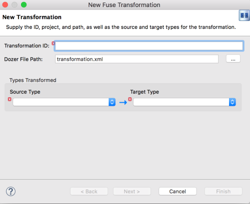
Fill in the remaining fields:
-
In the Transformation ID field, enter
xml2json. - For Source Type, select XML from the drop-down menu.
- For Target Type, select JSON from the drop-down menu.
-
In the Transformation ID field, enter
Click Next.
The Source Type (XML) definition page opens, where you specify either an XML Schema (default) or an example XML Instance Document to provide the type definition of the source data:
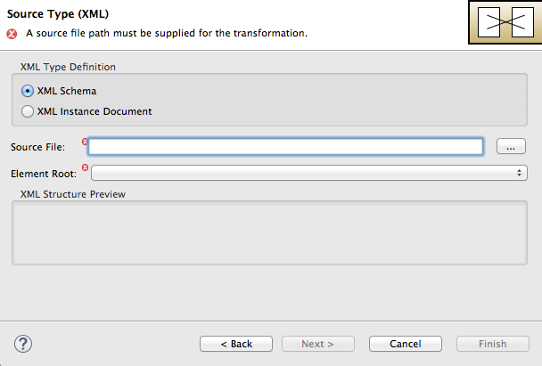
- Leave XML Schema enabled.
For Source file, browse to the location of the XML schema file or the XML instance file to use for the type definition of the source data, and select it (in this case,
abc-order.xsd).The XML Structure Preview pane displays a preview of the XML structure.
In the Element root field, enter
ABCOrder.The tooling uses this text to label the pane that displays the source data items to map.
The Source Type (XML) definition page should now look like this:
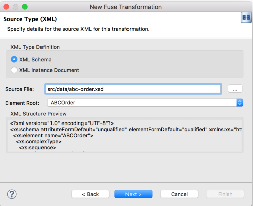
Click Next to open the Target Type (JSON) definition page. This is where you specify the type definition for the target data.
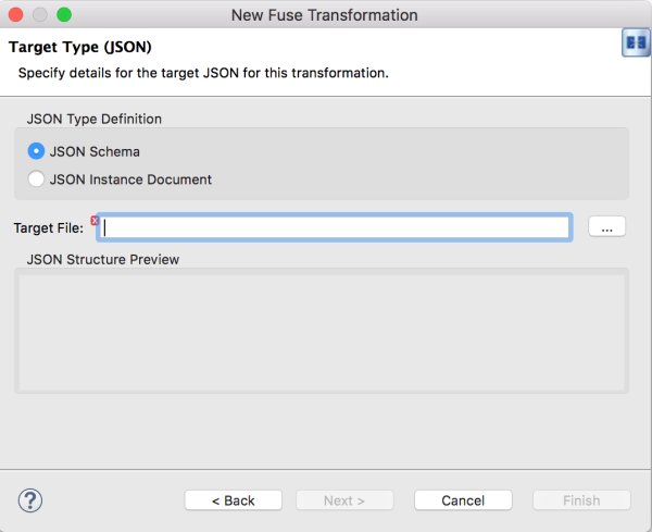
Click JSON Instance Document.
In the Target File field, enter the path to the
xyz-order.jsoninstance document, or browse to it. The JSON Structure Preview pane displays a preview of the JSON data structure:
- Click Finish.
The transformation editor opens. This is where you can map data items in your XML source to data items in your JSON target.
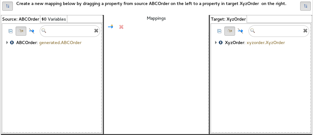
The transformation editor is composed of three panels:
- Source — lists the available data items of the source
- Mappings — displays the mappings between the source and target data items
- Target — lists the available data items of the target
In addition, the editor’s details pane, located just below the editor’s three panels (once the first mapping has been made), graphically displays the hierarchical ancestors for both the mapped source and target data items currently selected. For example:
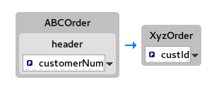
Using the details pane, you can customize the mapping for the selected source and target data items:
- Set property — Modify an existing mapping or map a simple data item to one in a collection (see Section 9.8, “Mapping a simple data item to a data item in a collection”).
- Set variable — Specify a constant value for a data item (see Section 9.5, “Mapping a constant variable to a data item”).
- Set expression — Map a data item to the dynamic evaluation of a specified expression (see Section 9.6, “Mapping an expression to a data item”).
- Add transformation — Modify the value of a mapped data item using a built-in function (see Section 9.9, “Adding a built-in function to a mapped data item”).
- Add custom transformation — Modify the value of a mapped data item using the Java method you create or one you previously created (see Section 9.7, “Adding a custom transformation to a mapped data item”).
9.3. Mapping source data items to target data items
Expand all items in the Source and Target panels located on left and right sides of the Mappings panel.
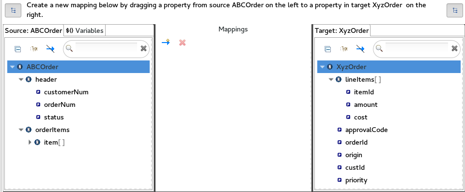
Drag a data item from the Source panel and drop it on its corresponding data item in the Target panel.
For example, drag the
customerNumdata item from the Source panel and drop it on thecustIddata item in the Target panel.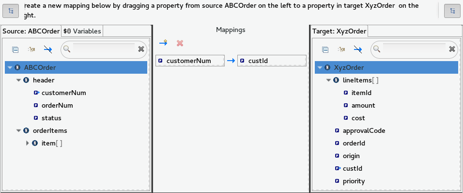
The mapping appears in the Mappings panel, and the details of both the Source and Target data items appear below in the details pane.
Continue dragging and dropping source data items onto their corresponding target data items until you have completed all basic mappings.
In the
starterexample, the remaining data items to map are:Source Target orderNumorderIdstatuspriorityiditemIdpricecostquantityamountNoteYou can map collections (data items containing lists or sets) to non-collection data items and vice versa, but you cannot map collections to other collections.
Click
 on both the Source and Target panels to quickly determine whether all data items have been mapped.
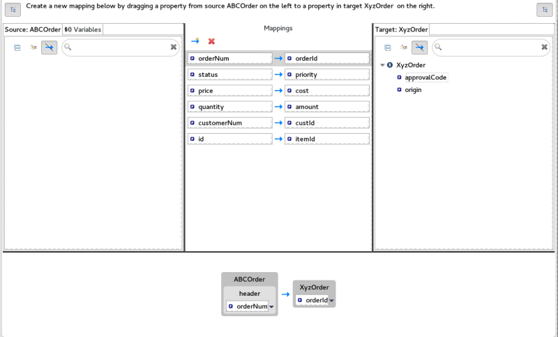
Only data items that have not been mapped are listed in the Source and Target panels.
In the
starterexample, the remaining unmapped Target attributes areapprovalCodeandorigin.Click the blueprint.xml tab to return to the graphical display of the route:
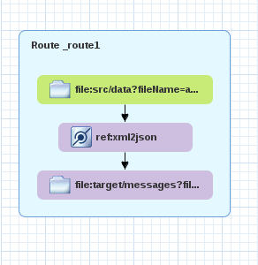
- Click File → Save.
You can run a JUnit test on your transformation file after you create the transformation test. For details, see Section 9.4, “Creating the transformation test file and running the JUnit test”. If you do so at this point, you will see this output in the Console view:
For the source XML data:
<?xml version="1.0" encoding="UTF-8"?>
<ABCOrder xmlns:xsi="http://www.w3.org/2001/XMLSchema-instance" xmlns:java="http://java.sun.com">
    <header>
        <status>GOLD</status>
        <customer-num>ACME-123</customer-num>
        <order-num>ORDER1</order-num>
    </header>
    <order-items>
        <item id="PICKLE">
            <price>2.25</price>
            <quantity>1000</quantity>
        </item>
        <item id="BANANA">
            <price>1.25</price>
            <quantity>400</quantity>
        </item>
    </order-items>
</ABCOrder>
For the target JSON data:
{"custId":"ACME-123","priority":"GOLD","orderId":"ORDER1","lineItems":[{"itemId":"PICKLE",
"amount":1000,"cost":2.25},{"itemId":"BANANA","amount":400,"cost":1.25
9.4. Creating the transformation test file and running the JUnit test
-
Right-click the
starterproject in the Project Explorer view, and select New → Other → Fuse Tooling → Fuse Transformation Test. - Select Next to open the New Transformation Test wizard.
In the New Transformation Test wizard, set the following values:
Field Value Package
exampleCamel File Path
OSGI-INF/blueprint/blueprint.xmlTransformation ID
xml2json- Click Finish.
-
In the Project Explorer view, navigate to
starter/src/test/java/example, and open theTransformationTest.javafile. Add the following code to the
transformmethod:startEndpoint.sendBodyAndHeader(readFile("src/data/abc-order.xml"), "approvalID", "AUTO_OK");Click File → Save.
You can now run a JUnit test on your transformation file at any point in these tutorials.
-
In the Project Explorer view, expand the
starterproject to expose the/src/test/java/example/TransformationTest.javafile. Right click it to open the context menu, and select Run as JUnit Test.
The JUnit Test pane opens to display the status of the test. To avoid cluttering your workspace, drag and drop the pane in the bottom panel near the Console view.

- Open the Console view to see the log output.
9.5. Mapping a constant variable to a data item
When a source/target data item has no corresponding target/source data item, you can map a constant variable to the existing data item.
In the starter example, the target data item origin does not have a corresponding source data item. To map the origin attribute to a constant variable:
In the Source panel, click the Variables view.
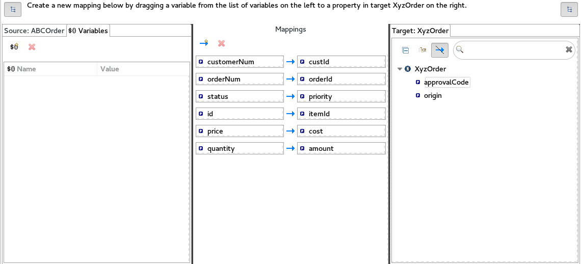
In the Variables view, click
 to open the Enter a new variable name dialog.
Enter a name for the variable you want to create.
For the
starterexample, enterORIGIN.Click OK.
The newly created variable
ORIGINappears in the Variables view in the Name column and the default valueORIGINin the Value column.-
Click the default value to edit it, and change the value to
Web. - Press Enter.
Drag and drop the new variable
ORIGINonto theorigindata item in the Target panel.
The new mapping of the variable
$(ORIGIN)appears in the Mappings panel and in the details pane.Run a JUnit test on your
TransformationTest.javafile. For details, see Section 9.4, “Creating the transformation test file and running the JUnit test”.The Console view displays the JSON-formatted output data:
{"custId":"ACME-123","priority":"GOLD","orderId":"ORDER1","origin":"Web",
"approvalCode":"AUTO_OK","lineItems":[{"itemId":"PICKLE","amount":1000,"cost":2.25},
{"itemId":"BANANA","amount":400,"cost":1.25}]}
9.6. Mapping an expression to a data item
This feature enables you, for example, to map a target data item to the dynamic evaluation of a Camel language expression.
Use the target approvalCode data item, which lacks a corresponding source data item:
Click
 to add an empty transformation map to the Mappings panel.
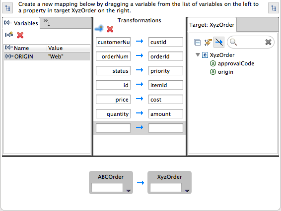
From the Target panel, drag and drop the
approvalCodedata item to the target field of the newly created mapping in the Mappings panel.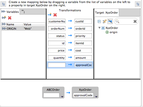
The
approvalCodedata item also appears in the details pane’s target box.In the details pane, click
 on the
 ABCOrdersource box to open the drop-down menu.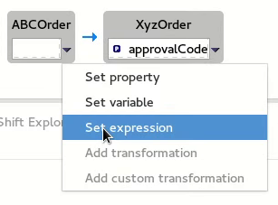
Menu options depend on the selected data item’s data type. The available options are bolded.
Select Set expression to open the Expression dialog.
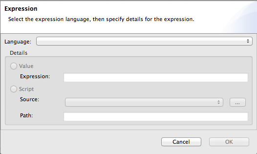
In Language, select the expression language to use from the list of those available. Available options depend on the data item’s data type.
For the
starterexample, select Header.In the details pane, select the source of the expression to use.
The options are Value and Script.
For the
starterexample, click Value, and then enterApprovalID.Click OK.
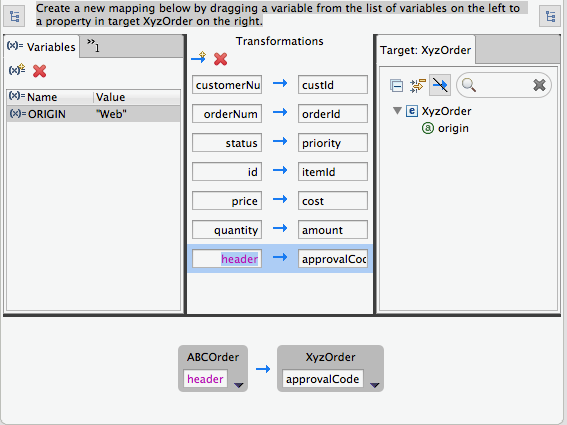
Both the Mappings panel and the details pane display the new mapping for the target data item
approvalCode.Run a JUnit test on your
TransformationTest.javafile. For details, see Section 9.4, “Creating the transformation test file and running the JUnit test”.The Console view displays the JSON-formatted output data:
{"custId":"ACME-123","priority":"GOLD","orderId":"ORDER1","origin":"Web",
"approvalCode":"AUTO_OK","lineItems":[{"itemId":"PICKLE","amount":1000,"cost":2.25},
{"itemId":"BANANA","amount":400,"cost":1.25}]}
9.7. Adding a custom transformation to a mapped data item
You may need to modify the formatting of source data items when they do not satisfy the requirements of the target system.
For example, to satisfy the target system’s requirement that all customer IDs be enclosed in brackets:
In the Mappings panel, select the
customerNummapping to populate the details pane.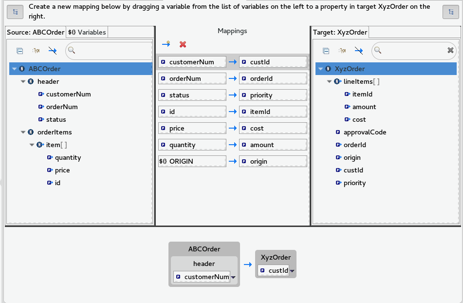
In the details pane, click
 on the
 ABCOrdersource box to open the drop-down menu.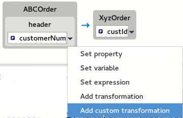
Select Add custom transformation to open the Add Custom Transformation page.
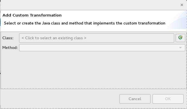
Click
 next to the Class field to open the Create a New Java Class wizard.
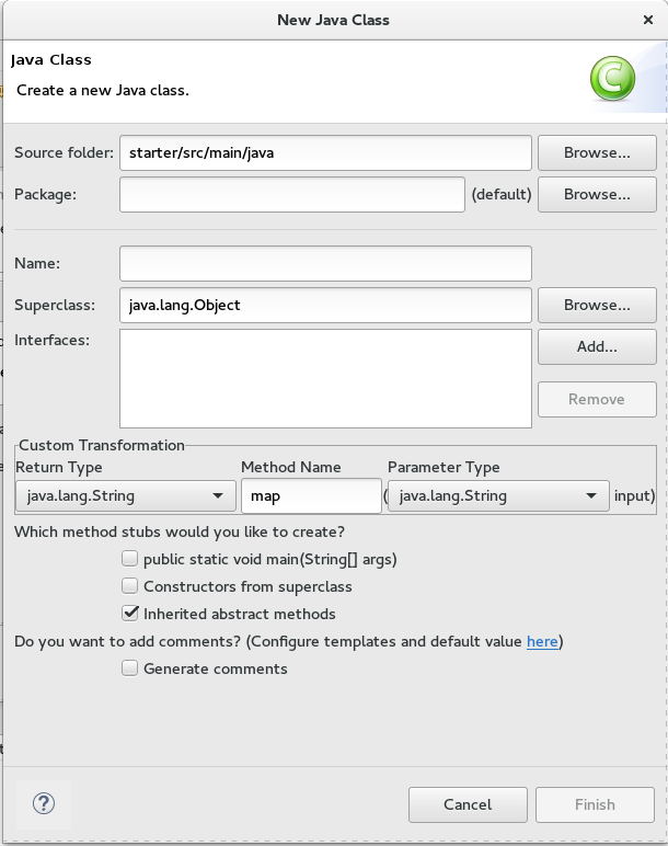
Modify the following fields:
-
Package — Enter
example. -
Name — Enter
MyCustomMapper. Method Name — Change
maptobrackets.Leave all other fields as is.
-
Package — Enter
Click Finish.
The Add Custom Transformation page opens with the Class and Method fields auto filled:

Click OK to open the
MyCustomMapper.javafile in the Java editor: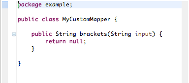
Edit the
bracketsmethod to change the last linereturn null;to this:return "[" + input + "]";
Click the transformation.xml tab to switch back to the transformation editor.
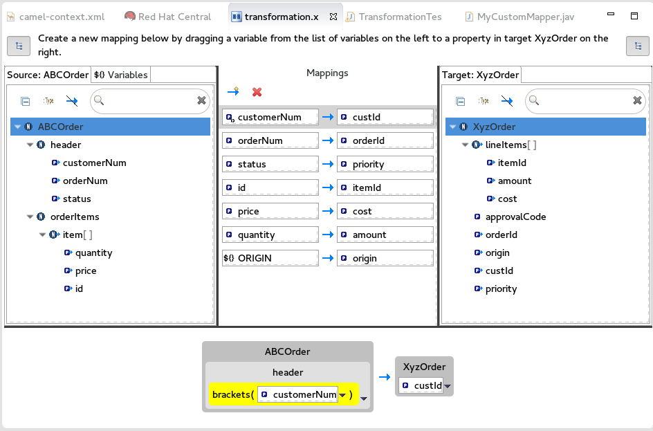
The details pane shows that the
bracketsmethod has been associated with thecustomerNumdata item.The
bracketsmethod is executed on the source input before it is sent to the target system.Run a JUnit test on your
TransformationTest.javafile. For details, see Section 9.4, “Creating the transformation test file and running the JUnit test”.The Console view displays the JSON-formatted output data:
{"custId":"[ACME-123]","priority":"GOLD","orderId":"ORDER1","origin":"Web",
"approvalCode":"AUTO_OK","lineItems":[{"itemId":"PICKLE","amount":1000,"cost":2.25},
{"itemId":"BANANA","amount":400,"cost":1.25}]}
9.8. Mapping a simple data item to a data item in a collection
In this tutorial, you will modify an existing mapping that maps all ids in the Source to the itemIds in the Target. The new mapping will map the customerNum data item in the Source to the itemId of the second item in the lineItems collection in the Target.
With this change, no ids in the Source will be mapped to itemIds in the Target.
In the Mappings panel, select the mapping
id— >itemIdto display the mapping in the details pane.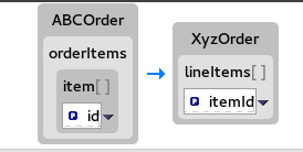
On the Source box, click
 to open the drop-down menu, and select Set property.

In the Select a property page, expand the
headernode and selectcustomerNum. Click OK to save the changes.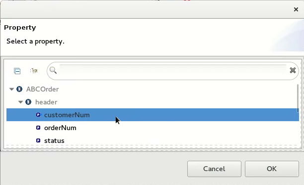
The details pane now shows that
XyzOrderhas alineItemsfield. Click the toggle button next tolineItemsto increase its value to1.NoteIndexes are zero-based, so a value of
1selects the second instance ofitemIdin the collection.
Notice that the details pane shows
customerNummapped to theitemIdof the second item in thelineItemscollection.Run a JUnit test on your
TransformationTest.javafile. For details, see Section 9.4, “Creating the transformation test file and running the JUnit test”.The Console view displays the JSON-formatted output data:
{"custId":"[ACME-123]","priority":"GOLD","orderId":"ORDER1","origin":"Web",
"approvalCode":"AUTO_OK","lineItems":[{"amount":1000,"cost":2.25},
{"itemId":"ACME-123","amount":400,"cost":1.25}]}
9.9. Adding a built-in function to a mapped data item
You can use the built-in string-related functions to apply transformations to mapped data items.
In the Transformations panel, select the
statustoprioritymapping to populate the details pane.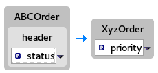
In the Source box, click
 to open the drop-down menu, and select Add transformation.
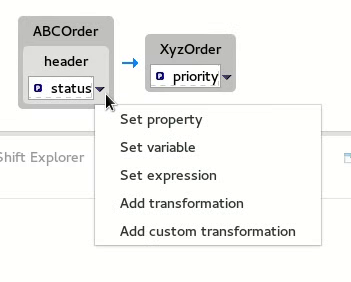
In the Transformations pane, select
append, and in the Arguments pane, enter-levelfor the value of suffix.This
appendfunction adds the specified suffix to the end of thestatusstring before mapping it to the targetprioritydata item.
Click OK.

By default, the details pane displays the results of adding the
appendfunction to thestatusdata item in a user-friendly format. You can change this formatting by clicking the right-most on the Source box, and selecting Show standard formatting.

Run a JUnit test on your
TransformationTest.javafile. For details, see Section 9.4, “Creating the transformation test file and running the JUnit test”.The Console view displays the JSON-formatted output data:
{"custId":"[ACME-123]","priority":"GOLD-level","orderId":"ORDER1","origin":"Web",
"approvalCode":"AUTO_OK","lineItems":[{"amount":1000,"cost":2.25},{"itemId":"ACME-123",
"amount":400,"cost":1.25}]}
9.10. Publishing a Fuse Integration project with data transformation to a Red Hat Fuse server
Before you publish your data transformation project to a Fuse server (see Chapter 29, Publishing Fuse Integration Projects to a Server), you need to install the following features in the Fuse runtime:
-
camel-dozer -
camel-jackson -
camel-jaxb
To install the required features on the Fuse runtime:
- If not already there, switch to the Fuse Integration perspective.
- If necessary, add the Fuse server to the Servers list (see Section 28.1, “Adding a Server”).
- Start the Fuse Server (see Section 28.2, “Starting a Server”), and wait for the JBoss Fuse shell to appear in the Terminal view.
For each of the required
camel-features, at theJBossFuse:admin@root>prompt type:features:install camel-<featureName>Where featureName is one of
dozer,jackson, orjaxb.To verify that each of the features was successfully installed, at the
JBossFuse:admin@root>prompt type:features:list --ordered --installedYou should see the camel features you just installed in the output listing:

Chapter 10. Developing extensions for Fuse Online integrations
Fuse Online is a Red Hat Fuse feature that provides a web interface for integrating applications. Without writing code, a business expert can use Fuse Online to connect to applications and optionally operate on data between connections to different applications. If Fuse Online does not provide a feature that an integrator needs, then a developer can create an extension that defines the needed behavior.
You can use Fuse Tooling to develop extensions that provide features for use in Fuse Online. An extension defines:
One or more custom steps that operate on data between connections in an integration
or
- One custom connector
In Fuse Online, a connector represents a specific application to obtain data from or send data to. Each connector is a template for creating a connection to that specific application. For example, the Salesforce connector is the template for creating a connection to Salesforce. If Fuse Online does not provide a connector that the Fuse Online user needs, you can develop an extension that defines a custom connector.
In Fuse Online, a data operation that happens between connections in an integration is referred to as a step. Fuse Online provides steps for operations such as filtering and mapping data. To operate on data between connections in ways that are not provided by Fuse Online built-in steps, you can develop a Fuse Online extension that defines one or more custom steps.
You might prefer to develop an extension in the IDE of your choice. Whether you use Fuse Tooling or another IDE is entirely a matter of personal preference. Information about developing an extension in any IDE is in Integrating Applications with Fuse Online.
10.1. Overview of tasks
Here is an overview of the tasks for developing a Fuse Online extension:
- In Red Hat CodeReady Studio, create a Fuse Online extension project and select Custom Connector or Custom Step as the extension type.
Depending on the extension type, write the code for the extension:
- For a Custom Connector: Define the base Camel component, the connector icon, global connector properties, and the connector actions.
- For a Custom Step: Add routes, define actions, and specify any dependencies.
-
Build a
.jarfile. -
Provide the
.jarfile to the Fuse Online user.
The Fuse Online user uploads the .jar file to Fuse Online, which makes the custom connector or custom step(s) available for use. For information about Fuse Online and how to create integrations, see Integrating Applications with Fuse Online.
10.2. Prerequisites
Before you begin, you need the following information and knowledge:
- A description of the required functionality for the Fuse Online custom connector or step (from the Fuse Online user).
- The Fuse Online version number for the extension.
- For a custom connector, an icon image file in PNG or SVG format. Fuse Online uses this icon when it displays the flow of an integration. If you do not provide an icon, then Fuse Online generates one when the .jar that contains the extension is uploaded.
You should be familiar with:
- Fuse Online
- Spring Boot XML or Java
- Apache Camel routes (if you want to create a route-based step extension)
- JSON
- Maven
10.3. Creating a custom connector
In Fuse Online, a custom connector consists of one or more connection configuration parameters, one or more connection actions, and optional configuration parameters for each action.
Here is an overview of the tasks for developing a custom connector:
- In Red Hat CodeReady Studio, create a Fuse Online extension project and select Custom Connector as the extension type.
- Write the code for the extension. Define the base Camel component, the connector icon, global connector properties, and the connector actions.
10.3.1. Creating a Fuse Online Extension project for a custom connector
A Fuse Tooling Fuse Online extension project provides a starting point for a custom connector.
To create a Fuse Tooling Fuse Online extension project, follow these steps:
In Red Hat CodeReady Studio, select New → Project → Red Hat Fuse → Fuse Online Extension Project.
The New Fuse Online Extension Project wizard opens.
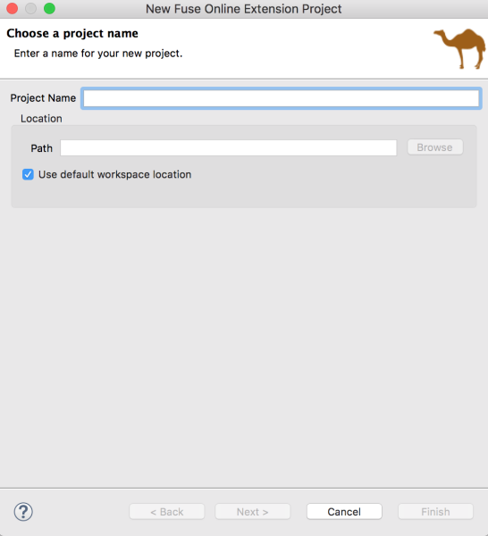
Enter the name and location for the project, then click Next.
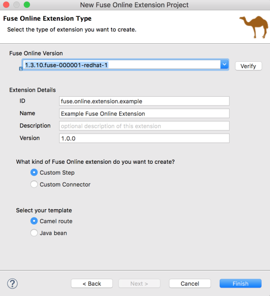
- Select the Fuse Online version.
Specify the following extension details:
-
ID — A value that you define and that is unique in the Fuse Online environment. This value will be visible in Fuse Online when the Fuse Online user imports the extension
.jarfile. - Name — The name of the extension. This value will be visible in Fuse Online as the extension name. In Fuse Online, on the Customizations → Extensions tab, the user can see a list of the names and descriptions of extensions that have been uploaded to Fuse Online.
- Description — An optional description of the extension content.
-
Version — The version of the extension. For example, if this is the initial version, you could type
1.0. If you are updating a version, you could type1.1or2.0.
-
ID — A value that you define and that is unique in the Fuse Online environment. This value will be visible in Fuse Online when the Fuse Online user imports the extension
Select Custom Connector for the kind of Fuse Online extension that you want to create.

- Click Finish.
The new project appears in the Red Hat CodeReady Studio Project Explorer view. It includes the following files for a custom connector extension:
In the
src/main/resources/META-INF/syndesisfolder:A descriptor file:
syndesis-extension-definition.jsonThis is the file that you edit to: * Add top-level global properties, connector actions, and action properties. * Change the Extension Id, Name, Version, or Description values.
A default icon image file:
icon.pngYou can optionally replace this file with your own icon image (PNG or SVG) file.
A Maven Project Object Model file:
pom.xmlThis file contains information about the project and configuration details used by Maven to build the project, including default extension dependencies. You edit this file to add custom dependencies. The scope for any dependency that Red Hat ships is provided, for example:
<dependency>
    <groupId>io.syndesis.extension</groupId>
    <artifactId>extension-api</artifactId>
    <scope>provided</scope>
</dependency>
<dependency>
    <groupId>org.apache.camel</groupId>
    <artifactId>camel-core</artifactId>
    <scope>provided</scope>
</dependency>
<dependency>
    <groupId>org.springframework.boot</groupId>
    <artifactId>spring-boot-starter</artifactId>
    <scope>provided</scope>
</dependency>
10.3.2. Writing code for the custom connector
After you create the Fuse Online extension project, you write the code that defines the custom connector elements based on the description of the required functionality provided to you by the Fuse Online user. The Table 10.1, “Custom connector elements” table shows how the elements of the custom connector that you create in Fuse Tooling correspond to elements in Fuse Online.
| Fuse Tooling element | Fuse Online element | Description |
|---|---|---|
| Global (top-level) property | Connection configuration parameter | When a Fuse Online user creates a connection from this connector, the user specifies a value for this property as part of the configuration of the connection. |
| Action | Connection action | In Fuse Online, for a connection created from this connector, a Fuse Online user selects one of these actions. |
| Property defined in an action | An action configuration parameter | When a Fuse Online user configures the action that the connection performs, the Fuse Online user specifies a value for this property as part of the configuration of the action. |
To write the code that implements a custom connector for Fuse Online:
Open the syndesis-extension-definition.json file in the Editor view and write the code that defines the global properties, the actions that the custom connector can perform, and each action’s properties.
Each global property corresponds to a connection configuration parameter in Fuse Online. Each action property corresponds to a Fuse Online connection action configuration parameter. In Fuse Online, when the user selects a custom connector, Fuse Online prompts for values for each connection configuration parameter. A custom connector can be for an application that uses the OAuth protocol. In this case, be sure to specify a global property for the OAuth client ID and another global property for the OAuth client secret. The Fuse Online user will need to specify values for these parameters for a connection created from this connector to work.
Each connector action declares a base Camel component scheme.
The example provided by the New Fuse Online Extension Project wizard uses the
telegramCamel component scheme:{ "schemaVersion" : "v1", "name" : "Example Fuse Online Extension", "extensionId" : "fuse.online.extension.example", "version" : "1.0.0", "actions" : [ { "id" : "io.syndesis:telegram-chat-from-action", "name" : "Chat Messages", "description" : "Receive all messages sent to the chat bot", "descriptor" : { "componentScheme" : "telegram", "inputDataShape" : { "kind" : "none" }, "outputDataShape" : { "kind" : "java", "type" : "org.apache.camel.component.telegram.model.IncomingMessage" }, "configuredProperties" : { "type" : "bots" } }, "actionType" : "connector", "pattern" : "From" }, { "id" : "io.syndesis:telegram-chat-to-action", "name" : "Send a chat Messages", "description" : "Send messages to the chat (through the bot).", "descriptor" : { "componentScheme" : "telegram", "inputDataShape" : { "kind" : "java", "type" : "java.lang.String" }, "outputDataShape" : { "kind" : "none" }, "propertyDefinitionSteps" : [ { "description" : "Chat id", "name" : "chatId", "properties" : { "chatId" : { "kind" : "parameter", "displayName" : "Chat Id", "type" : "string", "javaType" : "String", "description" : "The telegram's Chat Id, if not set will use CamelTelegramChatId from the incoming exchange." } } } ], "configuredProperties" : { "type" : "bots" } }, "actionType" : "connector", "pattern" : "To" } ], "properties" : { "authorizationToken" : { "kind" : "property", "displayName" : "Authorization Token", "group" : "security", "label" : "security", "required" : true, "type" : "string", "javaType" : "java.lang.String", "secret" : true, "description" : "Telegram Bot Authorization Token" } } }If the custom connector requires additional dependencies, add them to the project’s
pom.xmlfile. The default scope for dependencies is runtime. If you add a dependency that Red Hat ships, define its scope as provided, for example:<dependencies> <dependency> <groupId>org.apache.camel</groupId> <artifactId>camel-telegram</artifactId> <scope>provided</scope> </dependency> </dependencies>
When you finish writing the code for the custom connector, build the .jar file as described in Section 10.5, “Building the Fuse Online extension JAR file”.
10.4. Creating custom steps
After you create the Fuse Online extension project, you write the code that defines the custom steps based on the description of the required functionality provided to you by the Fuse Online user. Within a single extension, you can define more than one custom step and you can define each custom step with Camel routes or with Java beans.
10.4.1. Creating a Fuse Online Extension project for custom steps
To create a Fuse Tooling Fuse Online extension project, follow these steps:
In Red Hat CodeReady Studio, select New → Project → Red Hat Fuse → Fuse Online Extension Project.
The New Fuse Online Extension Project wizard opens.

Enter the name and location for the project, then click Next.

- Select the Fuse Online version.
Specify the following extension details:
-
ID — A value that you define and that is unique in the Fuse Online environment. This value will be visible in Fuse Online when the Fuse Online user imports the extension
.jarfile. - Name — The name of the extension. This value will be visible in Fuse Online as the extension name. In Fuse Online, on the Customizations → Extensions tab, the user can see a list of the names and descriptions of extensions that have been uploaded to Fuse Online.
- Description — An optional description of the extension content.
-
Version — The version of the extension. For example, if this is the initial version, you could type
1.0. If you are updating a version, you could type1.1or2.0.
-
ID — A value that you define and that is unique in the Fuse Online environment. This value will be visible in Fuse Online when the Fuse Online user imports the extension
- Select Custom Step for the kind of Fuse Online extension that you want to create.
Select the template for the custom step:
- Camel route — Provides a sample Camel route.
Java bean — Provides a sample Java bean.
NoteThe template that you select provides a starting point for your project. If you want to create one or more custom steps based on Camel routes and one or more other custom steps based on Java beans within the same extension, start with one of the templates and then add the needed file and dependencies for the other type of custom step.
- Click Finish.
The new project appears in the Red Hat CodeReady Studio Project Explorer view. It includes the following files depending on the template that you selected for the custom step:
In the
src/main/resources/META-INF/syndesisfolder:A descriptor file:
syndesis-extension-definition.jsonThis is the file that you edit to: * Add one or more actions. An action in the `.json `file becomes a custom step in Fuse Online. In an action element, a property in the `.json `file becomes a step configuration parameter in Fuse Online. * Change the Extension Id, Name, Version, or Description values.
For a Camel route template, a Camel context file:
extensions/log-body-action.xmlThis file contains a sample route with a log component. You customize the Camel routes in this file.
For a Java bean template, a Java file:
extensions/extension.javaThis file contains a sample POJO-based logging extension.
A Maven Project Object Model file:
pom.xmlThis file contains information about the project and configuration details used by Maven to build the project, including default extension dependencies. You edit this file to add custom dependencies. The scope for any dependency that Red Hat ships is provided, for example:
<dependency>
    <groupId>io.syndesis.extension</groupId>
    <artifactId>extension-api</artifactId>
    <scope>provided</scope>
</dependency>
<dependency>
    <groupId>org.apache.camel</groupId>
    <artifactId>camel-core</artifactId>
    <scope>provided</scope>
</dependency>
<dependency>
    <groupId>org.springframework.boot</groupId>
    <artifactId>spring-boot-starter</artifactId>
    <scope>provided</scope>
</dependency>
10.4.2. Writing code for the custom step
After you create the Fuse Online extension project, you write the code that defines the custom step(s)based on the description of the required functionality provided to you by the Fuse Online user.
Table 10.2, “Custom step elements” shows how the elements of the custom step that you create in Fuse Tooling correspond to elements in Fuse Online.
| Fuse Tooling element | Fuse Online element | Description |
|---|---|---|
| Action | Custom Step | In Fuse Online, after the user imports the step extension, the custom step(s) appear(s) on the Choose a step page. |
| Property defined in an action | A custom step configuration parameter | In Fuse Online, when the user selects a custom step, Fuse Online prompts for values for configuration parameters. |
To write the code that implements a custom step for Fuse Online:
For a Camel route-based step, in the
extension.xmlfile, create routes that address the purpose of the extension. The entrypoint of each route must match the entrypoint that you define in thesyndesis-extension-definition.jsonfile, as described in Step 2.For a Java bean-based step, edit the
javafile.In the
syndesis-extension-definition.jsonfile, write the code that defines the actions and their properties. You need a new action for each entrypoint.Each action that you create corresponds to a custom step in Fuse Online. You can use different types of code for each action. That is, you can use a Camel route for one action and a Java bean for another action.
Each property corresponds to a Fuse Online step configuration parameter. In Fuse Online, when the user selects a custom step, Fuse Online prompts for values for configuration parameters. For example, a custom log step might have a level parameter that indicates how much information to send to the log.
Here is the template for the
.jsonfile that contains the extension metadata, including properties that will be filled in by the user in Fuse Online after uploading the extension and adding its custom step to an integration:{ "actions": [ { "actionType": "extension", "id": "${actionId}", "name": "Action Name", "description": "Action Description", "tags": [ "xml" ], "descriptor": { "kind": "ENDPOINT|BEAN|STEP", "entrypoint": "direct:${actionId}", "inputDataShape": { "kind": "any" }, "outputDataShape": { "kind": "any" }, "propertyDefinitionSteps": [] } } ], "tags": [ "feature", "experimental" ] }NoteThe tags are ignored in this release. They are reserved for future use.
- To edit the extension dependencies, open the `pom.xml `file in the editor. If you add a dependency, you must define its scope.
When you finish writing the code for the custom step(s), build the .jar file as described in Section 10.5, “Building the Fuse Online extension JAR file”.
10.5. Building the Fuse Online extension JAR file
To build the .jar file for the extension:
- In the Project Explorer view, right-click the project.
- From the context menu, select Run As → Maven clean verify.
- In the Console view, you can monitor the progress of the build.
- When the build is complete, refresh the target folder in the Project Explorer view (select the project and then press F5).
In the Project Explorer view, open the target folder to see the generated
.jarfile:The name of the .jar file follows Maven defaults:
${artifactId}-${version}.jarFor example:
custom:step-camel-1.0.0.jarThis
.jarfile defines the extension, its required dependencies, and its metadata: Extension Id, Name, Version, Tags, and Description. For example:{ "schemaVersion" : "v1", "name" : "Example Fuse Online Extension", "description" : "Logs a message body with a prefix", "extensionId" : "fuse.online.extension.example", "version" : "1.0.0", "actions" : [ { "id" : "Log-body", "name" : "Log Body", "description" : "A simple xml Body Log with a prefix", "descriptor" : { "kind" : "ENDPOINT", "entrypoint" : "direct:log-xml", "resource" : "classpath:META-INF/syndesis/extensions/log-body-action.xml", "inputDataShape" : { "kind" : "any" }, "outputDataShape" : { "kind" : "any" }, "propertyDefinitionSteps" : [ { "description" : "Define your Log message", "name" : "Log Body", "properties" : { "prefix" : { "componentProperty" : false, "deprecated" : false, "description" : "The Log body prefix message", "displayName" : "Log Prefix", "javaType" : "String", "kind" : "parameter", "required" : false, "secret" : false, "type" : "string" } } } ] }, "tags" : [ "xml" ], "actionType" : "step" } ], "dependencies" : [ { "type" : "MAVEN", "id" : "io.syndesis.extension:extension-api:jar:1.3.0.fuse-000014" } ], "extensionType" : "Steps" }
10.6. Providing the JAR file to the Fuse Online user
Provide the following to the Fuse Online user:
-
The
.jarfile - A document that describes the extension. For a step extension, include information about data shapes that each action in the step extension requires as input or provides as output (for data mapping).
In Fuse Online, the user uploads the .jar file as described in Integrating Applications with Fuse Online.
Chapter 11. Creating a New Camel XML file
Overview
Apache Camel stores routes in an XML file that contains a camelContext element. When you create a new Fuse Integration project, the tooling provides an Apache Camel context (XML) file as part of the project by default.
You can also add a new Camel XML file that includes all of the required namespaces preconfigured and a template camelContext element.
Procedure
To add a new Apache Camel context file to your project:
Select File → New → Camel XML File from the main menu to open the Camel XML File wizard, as shown in Figure 11.1, “Camel XML File wizard”.
Figure 11.1. Camel XML File wizard
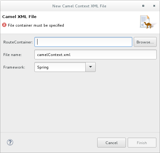
In RouteContainer, enter the location for the new file, or accept the default.
You can click
 to search for an appropriate location.
Important
to search for an appropriate location.
ImportantThe Spring framework and the OSGi Blueprint framework require that all Apache Camel files be placed in specific locations under the project’s
META-INForOSGI-INFfolder:-
Spring -
projectName/src/main/resources/META-INF/spring/ -
OSGi Blueprint -
projectName/src/main/resources/OSGI-INF/blueprint/
-
Spring -
In File Name, enter a name for the new context file, or accept the default (
camelContext.xml).The file’s name cannot contain spaces or special characters, and it must be unique within the JVM.
In Framework, accept the default, or select which framework the routes will use:
- Spring — [default] for routes that will be deployed in Spring containers, non-OSGi containers, or as standalone applications
- OSGi Blueprint — for routes that will be deployed in OSGi containers
-
Routes — for routes that you can load and add into existing
camelContexts
Click Finish.
The new context file is added to the project and opened in the route editor.
Chapter 12. Changing the Camel version
As you work with a Fuse tooling project, you might want to change the Camel version that it uses. This can be helpful, for example, if you want to use a feature supported in a more recent Camel version or if you want to use a community version.
To change the Camel version that a project uses:
- In Project Explorer, right-click the project for which you want to change the Camel version and select Configure → Change Camel Version.
In the Change Camel Version window, to the right of the Camel Version field, click the down caret to display available Camel versions.
To use a community version of Apache Camel, you enter its version number, for example,
2.19.2.- Select or enter the version you want and click Finish.
Fuse Tooling checks whether the version you selected is available and supported by Fuse Tooling. If it is then Fuse Tooling changes the Camel version and saves the project’s updated pom.xml file. You receive an error message if the Camel version that you select is not available or not supported.
You can check the project’s Camel version in its pom.xml file, in the <camel.version> element.
Chapter 13. Importing an existing Maven project
Overview
You might want to import an existing project, for example, to use as a template or starting point for developing an application.
For example, the New Fuse Integration Project wizard points to the following Github repositories as sources for examples:
After you download an example project, you import it into CodeReady Studio.
Procedure
To import an existing Maven project:
- Select File → Import → Maven → Existing Maven Projects, and then click Next.
- For the Root Directory, select the folder that contains the downloaded example projects.
- In the list of Projects, check the projects that you want to import and then click Finish.
Part II. Debugging Routing Contexts
The Camel debugger includes many features for debugging locally and remotely running routing contexts:
- Setting conditional and unconditional breakpoints on nodes in the route editor
- Autolaunching the debugger and switching to the Debug perspective
Interacting with the running routing context:
- Switch between breakpoints to quickly compare variable values of message instances
- Examine and change the value of variables of interest
- Add variables of interest to the watch list to track them throughout the debug session
- Disable and re-enable breakpoints on-the-fly
- Track message flow graphically in the routing context runtime
- Examine console logs to track Camel and debugger actions
Before you can run the Camel debugger, you must set breakpoints on the nodes of interest displayed on the route editor’s canvas. Then you can run the Camel debugger on a project’s routing context .xml file to find the logic errors in it and fix them. Invoking the Camel debugger runs the routing context in debug mode and opens the Debug Perspective.
Chapter 14. Setting Breakpoints
Overview
To set breakpoints, your project’s routing context .xml file must be open in the route editor’s Design tab.
The Camel debugger supports two types of breakpoints:
- Unconditional breakpoints — triggered whenever one is encountered during a debugging session
- Conditional breakpoints — triggered only when the breakpoint’s specified condition is met during a debugging session
You cannot set breakpoints on consumer endpoints or on when or otherwise nodes.
Setting unconditional breakpoints
With your routing context displayed on the canvas in the Design tab:
- Select a node whose state you want to examine during the debugging session.
-
Click its
 icon to set an unconditional breakpoint.
- Repeat these steps for each node on which you want to set an unconditional breakpoint.
Setting conditional breakpoints
With your routing context displayed on the canvas in the Design tab:
- Select a node whose state you want to examine during the debugging session.
Click its
 icon to set a conditional breakpoint and to open the Edit the condition and language of your breakpoint… dialog:
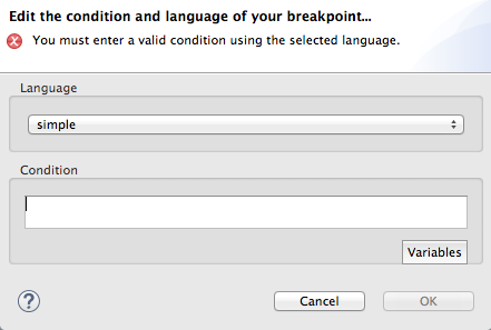
Click the Language drop-down menu and select the expression language to use to create the condition that will trigger the breakpoint.
Fuse Tooling supports twenty-four expression languages. Some of these languages provide variables for creating conditional expressions, while others do not.
Click Variables to display a list of the selected language’s supported variables.
If a list appears, select in sequence one or more of the variables to create the condition for triggering the breakpoint. The variables you select appear in the Condition text box.
If
 appears, enter the expression directly into the Condition text box.
- Repeat steps [condBpFirst] through [condBpLast] for each node on which you want to set a conditional breakpoint.
Disabling breakpoints
You can temporarily disable a breakpoint, leaving it in place, then enable it again later. The
 button skips over disabled breakpoints during debugging sessions.
To disable a breakpoint, select the node on the canvas and click its
 icon. The breakpoint turns gray, indicating that it has been disabled.
To enable a disabled breakpoint, select the node on the canvas and click its
 icon. Depending on whether the disabled breakpoint is conditional or unconditional, it turns yellow or red, respectively, to indicate that it has been re-enabled.
You can also disable and re-enable breakpoints during debugging sessions. For details, see Chapter 19, Disabling Breakpoints in a Running Context.
Deleting breakpoints
You can delete individual breakpoints or all breakpoints.
-
To delete individual breakpoints — in a route container, select the node whose breakpoint you want to delete, and click its
 icon.
icon.
-
To delete all breakpoints in a particular route — right-click the target route’s container, and select
 Delete all breakpoints
 -
To delete all breakpoints in all routes — right-click the canvas, and select
 Delete all breakpoints
Chapter 15. Running the Camel Debugger
You can run the Camel debugger on locally running routing contexts and on remotely running routing contexts. The same basic features and functionality are available in both debugging modes.
- Local debugging — Runs the debugger on the routing context running in the same JVM with Fuse Tooling. This mode is activated by selecting the project’s routing context in the Project Explorer view and selecting Debug As → Local Camel Context from the context menu.
- Remote debugging — Runs the debugger on a routing context running in a separate JVM either on the local machine or on a remote machine. This mode requires a supported runtime server installed on the local machine or on an accessible remote machine. It is activated by creating and running a debug launch configuration that specifies the remote runtime’s connection details.
If your project contains Java code, you can use the standard Eclipse Java debugging tools to debug it. For local debugging, it is automatically available. For remote debugging, you need to use the Remote Camel Context and Java launch option (see Section 15.2, “Debugging a remotely running routing context”).
You must set breakpoints in your routing context file before you can start the Camel debugger.
15.1. Debugging a locally running routing context
Procedure
- In the Project Explorer view, select the routing context file you want to debug.
Right-click the selected file to open the context menu, and then select Debug As → Local Camel Context.
Fuse Tooling builds the Camel route, starts Apache Camel, starts the routing context, enables JMX, starts the route(s) in the routing context, adds the breakpoints to the nodes, and enables the Camel debugger.
The Camel debugger suspends execution of the routing context at the first breakpoint hit (received a message), and prompts you to indicate whether you want it to open the Debug perspective.
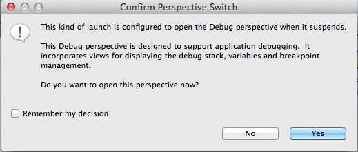
Click Yes to open the Debug perspective.
The Debug perspective opens with the routing context suspended at the first breakpoint encountered in the running routing context.
ImportantBreakpoints are held for a maximum of five minutes, after which debugging automatically resumes, moving on to the next breakpoint or to the end of the routing context.
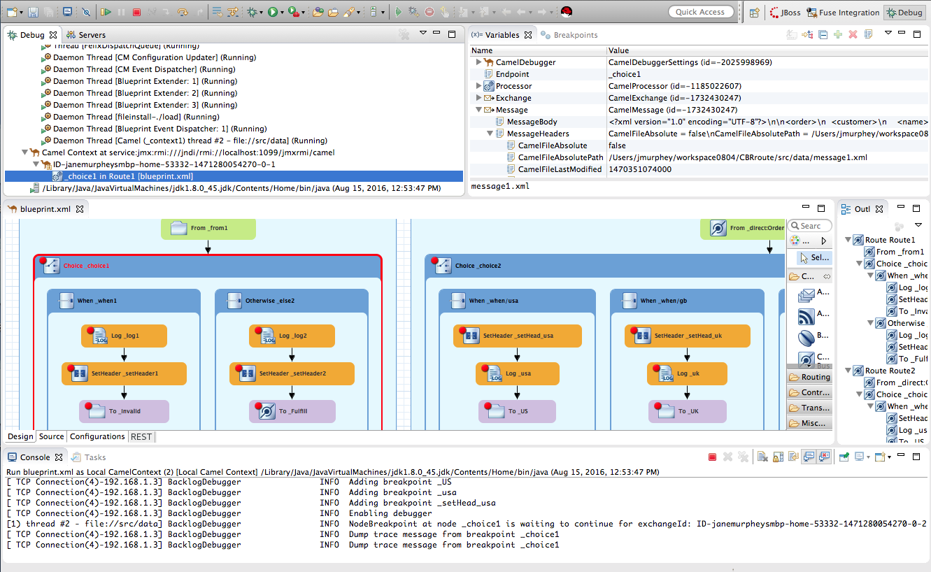 Note
NoteTo see the console output, open the Console view if it was not open when you switched perspectives.
NoteBy default, the Debug perspective displays the Outline view, which provides the means to switch between separate routes in a running routing context. If your routing context contains a single route, closing the Outline view frees space to expand the other views, making it easier to access and examine debugger output.
Watching message exchanges progress through the routing context
Click
 (Step Over) to jump to the next node of execution in the routing context. Click
 (Resume) to continue execution at the next active breakpoint in the routing context.
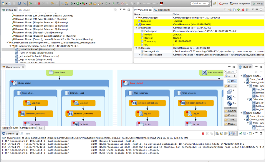
15.2. Debugging a remotely running routing context
Fuse servers deployed on a remote host cannot be registered in the Servers view of CodeReady Studio. Consequently, you cannot start, automatically redeploy, or stop remote Fuse servers from within CodeReady Studio. Instead, you must start Fuse in debug mode outside of CodeReady Studio.
Prerequisites
Access to a Fuse runtime in one of the following ways:
-
Install a Fuse server on your local machine and edit its
Fuse_HOME/etc/users.propertiesfile to activate theadminuser. For details, see Section 28.1, “Adding a Server”. -
Be able to access a Fuse server that is installed on a remote machine. You must know its connection details, including the credentials of the
adminuser.
-
Install a Fuse server on your local machine and edit its
Create a new Fuse Integration project, see the section called “Specifying the project name and workspace”. In the Fuse Integration project:
- Select the Camel version that matches the version of the Fuse server runtime.
Create an empty Blueprint DSL project or use one of the Fuse pre-defined templates with Blueprint DSL.
NoteThough not a requirement, it is a good idea to verify that you can run the project’s routing context successfully as a
Local Camel Context. For details, see Section 6.1, “Running routes as a local Camel context”.NoteThe examples in the section called “Setting up and starting remote debugging” are based on the Fuse → Content Based Router pre-defined template and a Red Hat Fuse 6.3.0 runtime.
In Red Hat CodeReady Studio:
- Add the Fuse server to the Servers view. For details, see Section 28.1, “Adding a Server”.
- Start the Fuse server. For details, see Section 28.2, “Starting a Server”.
- Publish your project to the Fuse Runtime server. For details, see the section called “Publishing Fuse projects automatically when resources change”.
- Verify that the project’s bundle is deployed and active. For details, see the section called “Verifying the project was published to the server”.
- Stop the Fuse Runtime server. For details, see Section 28.5, “Stopping a Server”.
Setting up and starting remote debugging
With the project deployed on Fuse and the server stopped, you need to set up and start remote debugging as follows:
Start Fuse in debug mode outside of Red Hat CodeReady Studio.
Fuse servers deployed on a remote host cannot be registered in the Servers view of CodeReady Studio, therefore you must start Fuse in debug mode outside of CodeReady Studio.
- In CodeReady Studio, set breakpoints on nodes in the project’s routing context, which is open in the route editor.
- Create a remote Camel context debug configuration and run it.
- Connect to Fuse runtime in the JMX Navigator view.
- Drop test messages in the JMX Navigator view on the input node of the Camel route running inside the Fuse runtime.
- Use any of the Camel debugger’s tools for debugging routes.
Procedure
To set up and start remote debugging:
Open a terminal outside of Red Hat CodeReady Studio, and enter
$ [FUSE_HOME]/bin/fuse debug
- Wait for the Fuse splash screen to appear, and then return to the Fuse Integration perspective in CodeReady Studio.
- In the tooling’s route editor, with the project’s routing context open in the Design tab, set breakpoints on the nodes of interest. For details, see Chapter 14, Setting Breakpoints.
In the Project Explorer view, right-click the project’s root and select Debug As → Debug Configurations to open the Debug Configurations wizard:
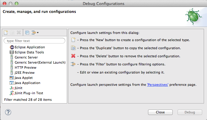
In the configuration type pane, select either Remote Camel Context or Remote Camel Context and Java , and then click
 :
:
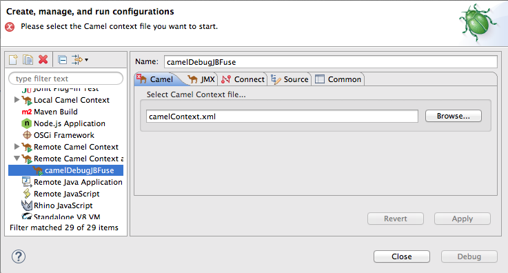
For both the Remote Camel Context and Remote Camel Context and Java options, you need to specify configuration details on the Camel and JMX tabs.
For the Remote Camel Context and Java option only, you also need to specify configuration details on the Connect tab.
NoteUnless your project contains Java code that you want to debug using the standard Eclipse Java debugging tools, select the Remote Camel Context option.
- In the Name field, enter a name for the new launch configuration.
On the Camel tab, click the Browse button to locate the project’s routing context
.xmlfile in the Open Resources dialog: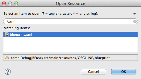 Note
NoteWhen you select a file in the Matching items pane, the tooling displays the file’s location, relative to the project root, at the bottom of the pane.
In the Matching items pane, select your project’s routing context file from the list, and then click OK.
The tooling inserts the file’s path into the Select Camel Context file field:
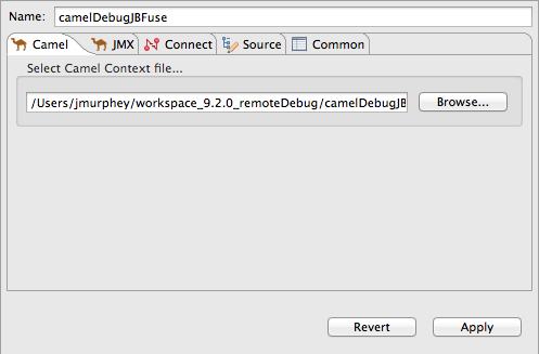
Click the JMX tab:
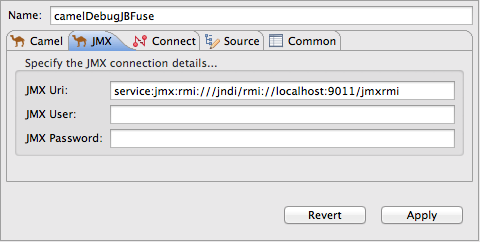
Edit the JMX connection details as follows:
JMX Uri — change
:9011/jmxrmito:1099/karaf-rootIf the Fuse server is running on a remote host, replace
localhostwith the DNS name or IP address of the remote host.-
JMX User — enter
admin. JMX Password — enter
admin.ImportantThe values shown for JMX User and JMX Password are the Fuse admin user defaults, stored in the
Fuse_HOME/etc/users.propertiesfile. If your setup is different, enter the values specific to it.If you are creating a Remote Camel Context debug launch configuration, you are done. Skip to [debugCfgGo].
Click the Connect tab:
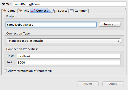
Change the Port value from
8000to5005. Leave each of the other properties as is.- Click Apply and then click Debug.
- In the JMX Navigator view, double-click Fuse [xxx] [Disconnected] to connect to it, and then expand its tree.
In the Project Explorer view, drag a test message from
src/test/resources/dataand drop it on thecbr-example-context/Endpoints/file/work/cbr/inputfolder in the JMX Navigator view.When the message hits the first breakpoint that is set in the routing context, the tooling asks you to switch to the Debug perspective:

Click Yes.
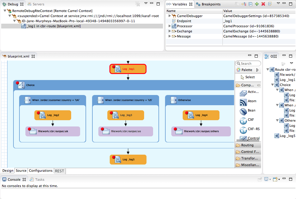
At this point, you can use any of the Camel debugger’s tools to debug your routing context.
NoteIn remote debugging sessions, the Console view does not display log output.
NoteWhen one message reaches the end of the routing context, the debugger is suspended. To continue debugging, switch back to the Fuse Integration perspective and drop another message on the input node in the JMX Navigator view. Each time you do so, the tooling asks you to confirm the switch to the Debug perspective.
Chapter 16. Stopping the Camel Debugger
Overview
The way to stop the Camel debugger depends on the mode in which it is running:
Local debugging (Section 15.1, “Debugging a locally running routing context”)
To stop the Camel debugger, click
 on the menu bar once if the debugging session has ended. Otherwise, click
 twice: once to terminate the currently running node thread and once to terminate the
 Camel Contextthread (both displayed in the Debug view).NoteTerminating the Camel debugger also terminates the console but does not clear its output. To clear the output, click
 (Clear Console) on the Console view’s menu bar.
Remote debugging (Section 15.2, “Debugging a remotely running routing context”)
To stop the Camel debugger, select the
[Remote Camel Context]thread or the[Remote Camel Context and Java]thread in the Debug view, and then click on the menu bar.
Note
on the menu bar.
NoteTerminating the Camel debugger does not close the connection to the remote runtime server in the Servers view nor in the JMX Navigator view.
Closing the Camel debugger
After you have finished debugging your project, you may want to close the Debug perspective to make more space for your workbench.
To do so, right-click
![]() on the right side of the CodeReady Studio toolbar, and then select Close.
on the right side of the CodeReady Studio toolbar, and then select Close.
Chapter 17. Changing Variable Values
Overview
When the Camel debugger hits a breakpoint, the Variables view displays the values of all variables available at that point in the routing context. Some variables are editable, allowing you to change their value. This enables you to see how the application handles changes in program state.
Not all variables are editable. The context menu of editable variables displays the Change Value… option.
Procedure
To change the value of a variable:
- If necessary, start the debugger. See Chapter 15, Running the Camel Debugger.
In the Variables view, select a variable whose value you want to change, and then click its Value field.
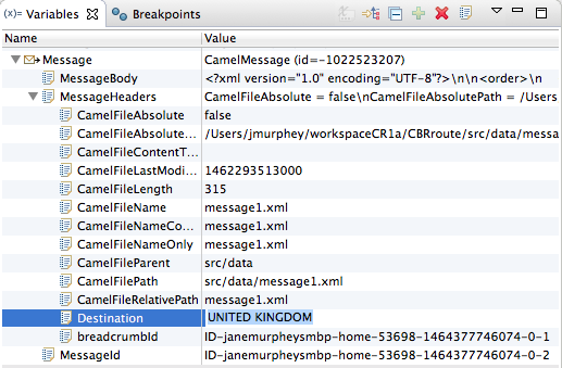
The variable’s value field turns a lighter shade of blue, indicating that it is in edit mode.
NoteAlternatively, you can right-click the variable to open its context menu, and select Change Value… to edit its value.
Enter the new value and then click Enter.
The Console view displays an
INFOlevel log entry noting the change in the variable’s value (for example,Breakpoint at node to1 is updating message header on exchangeId: ID-dhcp-97-16-bos-redhat-com-52574-1417298894070-0-2 with header: Destination and value: UNITED KINGDOM).- Continue stepping through the breakpoints and check whether the message is processed as expected. At each step, check the Debug view, the Variables view, and the Console output.
Chapter 18. Adding Variables to the Watch List
Overview
By adding variables to the watch list, you can focus on particular variables to see whether their values change as expected as they flow through the routing context.
Procedure
To add a variable to the watch list:
- If necessary, start the debugger. See Chapter 15, Running the Camel Debugger.
In the Variables view, right-click a variable you want to track to open the context menu.

Select Watch.
A new view, Expressions, opens next to the Breakpoints view. The Expressions view displays the name of the variable being watched and its current value, for example:

Repeat [watch1] and [watch2] to add additional variables to the watch list.
NoteThe variables you add remain in the watch list until you remove them. To stop watching a variable, right-click it in the list to open the context menu, and then click Remove.
- With the Expressions view open, step through the routing context to track how the value of each variable in the watch list changes as it reaches each step in the route.
Chapter 19. Disabling Breakpoints in a Running Context
Overview
You can disable and re-enable breakpoints in a running routing context in the Breakpoints view.
When a breakpoint is disabled, the
 button causes the debugger to skip over it during the debugging session.
Disabling and enabling breakpoints in Breakpoints view
The Breakpoints view opens with all set breakpoints enabled.
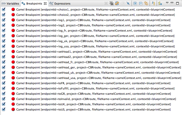
To disable a breakpoint, clear its check box.
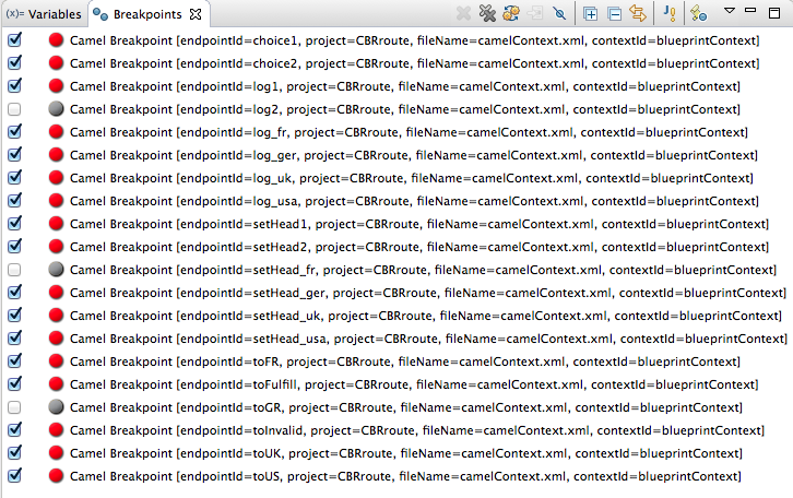
For each breakpoint you disable, the Console view displays an INFO level log entry noting that it has been disabled (for example, Removing breakpoint log2). Likewise, for each breakpoint you re-enable, the Console view displays an INFO level log entry noting that it has been enabled (for example, Adding breakpoint log2).
To re-enable a disabled breakpoint, click its check box. The Console view displays an INFO level log entry noting that the breakpoint has been added to the selected node.
Part III. Monitoring and Testing Applications
The JMX Navigator view provides numerous ways to monitor and test your Fuse applications.
You can also monitor your Fuse applications with the Fuse Console as described in Managing Fuse.
Chapter 20. JMX Navigator
The JMX Navigator view, shown in Figure 20.1, “JMX Navigator view”, displays all processes that are running in your application and it drives all interactions with the monitoring and testing features. Other areas of the Fuse Integration perspective adapt to display information related to the node selected in the JMX Navigator view. In the JMX Navigator view, its context menu provides the commands needed to activate route tracing and to add JMS destinations.
Figure 20.1. JMX Navigator view
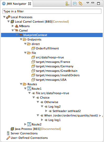
By default, the JMX Navigator view discovers all JMX servers running on the local machine and lists them under the following categories:
- Local Processes
- Server Connections
- User-Defined Connections
You can add other JMX servers by using a server’s JMX URL. For details, see Section 20.2, “Adding a JMX server”.
20.1. Viewing Processes in JMX
Overview
The JMX Navigator view lists all known processes in a series of trees. The root for each tree is a JMX server.
The first tree in the list is a special Local Processes tree that contains all JMX servers that are running on the local machine. You must connect to one of the JMX servers to see the processes it contains.
Viewing processes in a local JMX server
To view information about processes in a local JMX server:
- In the JMX Navigator view, expand Local Processes.
- Under Local Processes, double-click one of the top-level entries to connect to it.
-
Click the
 icon that appears next to the entry to display a list of its components that are running in the JVM.
Viewing processes in alternate JMX servers
To view information about processes in an alternate JMX server:
- Section 20.2, “Adding a JMX server” the JMX server to the JMX Navigator view.
-
In the JMX Navigator view, expand the server’s entry by using the
 icon that appears next to the entry. This displays a list of that JMX server’s components that are running in the JVM.
20.2. Adding a JMX server
Overview
In the JMX Navigator view, under the Local Processes branch of the tree, you can see a list of all local JMX servers. You may need to connect to specific JMX servers to see components deployed on other machines.
To add a JMX server, you must know the JMX URL of the server you want to add.
Procedure
To add a JMX server to the JMX Navigator view:
-
In the JMX Navigator view, click New Connection
 .
.
- In the Create a new JMX connection wizard, select Default JMX Connection.
- Click Next.
- Select the Advanced tab.
In the Name field, enter a name for the JMX server.
The name can be any string. It is used to label the entry in the JMX Navigator tree.
- In the JMX URL field, enter the JMX URL of the server.
- If the JMX server requires authentication, enter your user name and password in the Username and Password fields.
Click Finish.
The new JMX server appears as a branch in the User-Defined Connections tree.
Chapter 21. Viewing a component’s JMX statistics
Overview
The tooling collects all JMX statistics reported by Fuse components and displays them in the Properties view. This statistical information can provide significant insight into what is happening in your integration application.
JMX statistics are grouped into three categories: Properties, Processor, and Profile.
Procedure
To see a Fuse component’s statistics:
In the JMX Navigator view, locate the node for the component.
You may have to expand nodes on the tree to locate low-level components.
- Select the node of the Fuse component whose statistics you want to review.
- Open the Properties view.
The Properties page displays the JMX properties for the selected component:
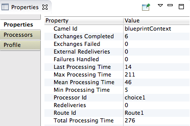
Click Processors to check exchange metrics for the selected component:

Click Profile to check message metrics for the selected node and its subnodes:

Chapter 22. Browsing messages
Overview
A key tool in debugging applications in a distributed environment is seeing all of the messages stored in the JMS destinations and route endpoints in the application. The tooling can browse the following:
- JMS destinations
- JMS routing endpoints
- Apache Camel routing endpoints
- SEDA routing endpoints
- Browse routing endpoints
- Mock routing endpoints
- VM routing endpoints
- DataSet routing endpoints
Procedure
To browse messages:
In the JMX Navigator view, select the JMS destination or endpoint you want to browse.
The list of messages appears in the Messages View.
In the Messages View, select an individual message to inspect.

Message details and content are displayed in the Properties view:

Chapter 23. Tracing Routes
Debugging a route often involves solving one of two problems:
- A message was improperly transformed.
- A message failed to reach its destination endpoint.
Tracing one or more test messages through the route is the easiest way to discover the source of such problems.
The tooling’s route tracing feature enables you to monitor the path a message takes through a route and see how the message is transformed as it passes from processor to processor.
The Diagram View displays a graphical representation of the route, which enables you to see the path a message takes through it. For each processor in a route, it also displays the average processing time, in milliseconds, for all messages processed since route start-up and the number of messages processed since route start-up.
The Messages View displays the messages processed by a JMS destination or route endpoint selected in the JMX Navigator tree. Selecting an individual message trace in the Messages View displays the full details and content of the message in the Properties view and highlights the correspoding node in the Diagram View.
Tracing messages through a route involves the following steps:
23.1. Creating test messages for route tracing
Overview
Route tracing works with any kind of message structure. The Fuse Message wizard creates an empty .xml message, leaving the structuring of the message entirely up to you.
If the folder where you want to store the test messages does not exist, you need to create it before you create the messages.
Creating a new folder to store test messages
To create a new folder:
- In the Project Explorer view, right-click the project root to open the context menu.
Select New → Folder to open the New Folder wizard.
The project root appears in the Enter or select the parent folder field.
- Expand the nodes in the graphical representation of the project’s hierarchy, and select the node you want to be the parent folder.
- In the Folder name field, enter a name for the new folder.
Click Finish.
The new folder appears in the Project Explorer view, under the selected parent folder.
NoteIf the new folder does not appear, right-click the parent foler and select Refresh.
Creating a test message
To create a test message:
- In the Project Explorer view, right-click the project to open the context menu.
- Select New → Fuse Message to open the New File wizard.
- Expand the nodes in the graphical representation of the project’s hierarchy, and select the folder in which you want to store the new test message.
-
In the File name field, enter a name for the message, or accept the default (
message.xml). Click Finish.
The new message opens in the XML editor.
Enter the message contents, both body and header text.
NoteYou may see the warning,
No grammar constraints (DTD or XML Schema) referenced in the document, depending on the header text you entered. You can safely ignore this warning.
23.2. Activating route tracing
Overview
You must activate route tracing for the routing context before you can trace messages through that routing context.
Procedure
To activate tracing on a routing context:
In the JMX Navigator view, select the running routing context on which you want to start tracing.
NoteYou can select any route in the context to start tracing on the entire context.
Right-click the selected routing context to open the context menu, and then select Start Tracing to start the trace.
If Stop Tracing Context is enabled on the context menu, then tracing is already active.
23.3. Tracing messages through a routing context
Overview
The best way to see what is happening in a routing context is to watch what happens to a message at each stop along the way. The tooling provides a mechanism for dropping messages into a running routing context and tracing the path the messages take through it.
Procedure
To trace messages through a routing context:
- Create one or more test messages as described in Section 23.1, “Creating test messages for route tracing”.
In the Project Explorer view, right-click the project’s Camel context file to open the context menu, and select Run As → Local Camel Context (without Tests).
NoteDo not run it as Local Camel Context unless you have created a comprehensive JUnit test for the project.
- Activate tracing for the running routing context as described in Section 23.2, “Activating route tracing”.
- Drag one of the test messages from the Project Explorer view onto the routing context’s starting point in the JMX Navigator view.
In the JMX Navigator view, select the routing context being traced.
The tooling populates the Messages View with message instances that represent the message at each stage in the traced context.
The Diagram View displays a graphical representation of the selected routing context.
In the Messages View, select one of the message instances.
The Properties view displays the details and content of the message instance.
In the Diagram View, the route step corresponding to the selected message instance is highlighted. If the route step is a processing step, the tooling tags the exiting path with timing and processing metrics.
- Repeat this prodedure as needed.
23.4. Deactivating route tracing
Overview
When you are finished debugging the routes in a routing context, you should deactivate tracing.
Deactivating tracing stops tracing and flushes the trace data for all of the routes in the routing context. This means that you cannot review any past tracing sessions.
Procedure
To stop tracing for a routing context:
In the JMX Navigator view, select the running routing context for which you want to deactivate tracing.
NoteYou can select any route in the context to stop tracing for the context.
Right-click the selected routing context to open the context menu, and then select Stop Tracing Context.
If Start Tracing appears on the context menu, tracing is not activated for the routing context.
Chapter 24. Managing JMS destinations
The JMX Navigator view lets you add or delete JMS destinations in a running instance of Red Hat Fuse.
These changes are not persistent across broker restarts.
24.1. Adding a JMS destination
Overview
When testing a new scenario, it is convenient to add a new JMS destination to one of your brokers.
Procedure
To add a JMS destination to a broker:
- In the JMX Navigator view, under the broker node for which you want to add a destination, select either the Queues child or the Topics child.
- Right-click the selected node to open the context menu, and then select either Create Queue or Create Topic.
- In either the Create Queue or Create Topic dialog, enter a name for the new destination.
- Click OK.
Right-click either the Queues or the Topics child, and then select Refresh.
The new destination appears in the JMX Navigator view under the Queues child or the Topics child.
24.2. Deleting a JMS destination
Overview
When testing failover scenarios or other scenarios that involve handling failures, it is helpful to be able to easily remove a JMS destination.
Procedure
To delete a JMS destination:
- In the JMX Navigator view, under the Queues child or the Topics child, select the JMS destination you want to delete.
- Right-click the selected destination to open the context menu, and then select Delete Queue/Topic.
Chapter 25. Managing routing endpoints
The JMX Navigator view lets you add or delete routing endpoints.
These changes are not persistent across routing context restarts.
25.1. Adding a routing endpoint
Overview
When testing a new scenario, you might want to add a new endpoint to a routing context.
Procedure
To add an endpoint to a routing context:
- In the JMX Navigator view, under the routing context node, select the Endpoints child to which you want to add an endpoint.
- Right-click the selected node to open the context menu, and then select Create Endpoint.
-
In the Create Endpoint dialog, enter a URL that defines the new endpoint, for example,
file://target/messages/validOrders. - Click OK.
Right-click the routing context node, and select Refresh.
The new destination appears in the JMX Navigator view under the Endpoints node, in a folder that corresponds to the type of endpoint it is, for example, file.
25.2. Deleting a routing endpoint
Overview
When testing failover scenarios or other scenarios that involve handling failures, it is helpful to be able to remove an endpoint from a routing context.
Procedure
To delete a routing endpoint:
- In the JMX Navigator view, select the endpoint you want delete.
Right-click the selected endpoint to open the context menu, and then select Delete Endpoint.
The tooling deletes the endpoint.
To remove the deleted endpoint from the view, right-click the Endpoints node, and select Refresh.
The endpoint disappears from the JMX Navigator view.
NoteTo remove the endpoint’s node from the Project Explorer view without rerunning the project, you need to explicitly delete it by right-clicking the node and selecting Delete. To remove it from view, refresh the project display.
Chapter 26. Editing running routes
Overview
You can experiment with changes to a running route without changing your project’s routing context.
To do so:
In the JMX Navigator view, enable the Edit Routes option on the running routing context.
This opens an in-memory model of it — Remote CamelContext:<camelContextId> — in the route editor.
In the route editor, make your changes to the in-memory model of the routing context. At the same time, you can set breakpoints on relevant nodes to use the Camel debugger and all of its features.
You can edit the in-memory model to add, remove, or rearrange nodes; to add or remove properties of existing nodes; and to modify property values set on existing nodes. You must save changes made to the in-memory model to update the running context and to see results in the Debug perspective if you set breakpoints.
- In the JMX Navigator view, drop messages on the running routing context, or wait for messages to arrive from a timer, ActiveMQ, file, or other continuous input node.
- In the Debug perspective, evaluate results and use the Camel debugger to gain deeper insight into your routing context.
Modifying a running route and evaluating results
- In the JMX Navigator view, select the routing context that contains the routes you want to edit.
Right-click the selected routing context to open the context menu, and select Edit Routes.
The route editor opens an in-memory model of the routing context, Remote CamelContext:<contextId>, and displays all routes in the context, for example:
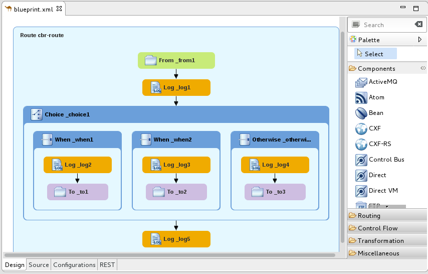 Note
Note<contextId>is the ID of thecamelContextelement in the project’s routing context .xmlfile. In this example, which is based on the Fuse → Content Based Router built-in template, the ID iscbr-example-context.- Edit the route as described in Chapter 2, Editing a routing context in the route editor, then select File → Save to save the changes you made to the in-memory model and to update the running routing context.
- Set breakpoints on the relevant nodes as described in Chapter 14, Setting Breakpoints.
In the JMX Navigator view, drop a message on the running routing context’s input node.
If your project does not include test messages, you can create them as described in Section 23.1, “Creating test messages for route tracing”.
- Click Yes to confirm the switch to the Debug perspective.
In the Camel debugger, step the message through the breakpoints as you normally would (see Chapter 15, Running the Camel Debugger) to see the results your changes generated.
The Camel debugger behaves the same in Edit Routes mode as in normal debug mode, so you can use any of the Camel debugger’s features while a message is transiting the routing context.
NoteWhen a message reaches the end of the routing context, the debugger is suspended. To continue debugging, switch back to the Fuse Integration perspective and drop another message on the input node in the JMX Navigator view. Each time you do so, the tooling asks you to confirm the switch to the Debug perspective.
NoteDuring a route editing session, it is possible to lose the connection to the running routing context. If this happens, then in the JMX Navigator view, you would see something like this: Local Processes → maven[xxxx][Disconnected]. To continue the session, you must reconnect to the running routing context, select it in the JMX Navigator view, and then re-select Edit Routes.
Terminating the route editing session
-
In the Debug perspective’s Debug view, select the Remote Camel Debug - camelContext--<contextId>--xxxxxxxxxxxxxxxxxx.xml [Remote Camel Context] thread, and then click
 on the menu bar to terminate the debugging session.
-
On Console view’s menu bar, click
 to terminate the routing context.
-
If you want to clear console output, click
 on the Console view’s menu bar.
-
Switch to the Fuse Integration perspective, and in the route editor, click
 on the Remote CamelContext:<contextId> tab to close the in-memory model of the routing context file.
Chapter 27. Managing routing contexts
The JMX Navigator view lets you suspend and resume running routing contexts.
27.1. Suspending operation of a routing context
Overview
The tooling enables you to suspend the operation of a routing context in the JMX Navigator view. Suspending context operation gracefully shuts down all routes in the context, but keeps them loaded in memory, so that they can resume operation.
Procedure
To suspend operation of a routing context:
- In the JMX Navigator view, expand the project’s Camel Contexts node, and select the routing context whose operation you want to suspend.
Right-click the selected routing context to open the context menu, and then select Suspend Camel Context.
NoteIf Resume Camel Context appears on the context menu, operation of the context is already suspended.
27.2. Resuming operation of a routing context
Overview
The tooling lets you resume operation of a suspended routing context in the JMX Navigator view. Resuming operation of a context restarts all of the routes in it so that they can process messages.
Procedure
To resume operation of a routing context:
- In the JMX Navigator view, expand the project’s Camel Contexts node, and select the routing context whose operation you want to resume.
Right-click the selected context to open the context menu, and then select Resume Camel Context.
NoteIf Suspend Camel Context appears in the context menu, the context and its routes are running.
Part IV. Publishing Applications to a Container
To publish Fuse Integration projects to a server container, you must first add the server and its runime definition to the tooling’s Servers list. Then you can assign projects to the server runtime and set the publishing options for it.
Chapter 28. Managing servers
The Servers view lets you run and manage servers in your Red Hat CodeReady Studio environment.
For step by step instructions on how to publish a Camel project to Red Hat Fuse, see Chapter 29, Publishing Fuse Integration Projects to a Server.
28.1. Adding a Server
Overview
For the tooling to manage a server, you need to add the server to the Servers list. Once added, the server appears in the Servers view, where you can connect to it and publish your Fuse Integration projects.
If adding a Red Hat Fuse server, it is recommended that you edit its installDir/etc/users.properties file and add user information, in the form of user=password,role, to enable the tooling to establish an SSH connection to the server.
Procedure
There are three ways to add a new server to the Servers view:
In the Servers view, click
No servers are available. Click this link to create a new server….NoteThis link appears in the Servers view only when no server has been defined. If you defined and added a server when you first created your project, the Servers view displays that server.
- In the Servers view, right-click to open the context menu and select New → Server.
- On the menu bar, select File → New → Other → Server → Server.
In the Define a New Server dialog, to add a new server:
Expand the Red Hat JBoss Middleware node to expose the list of available server options:
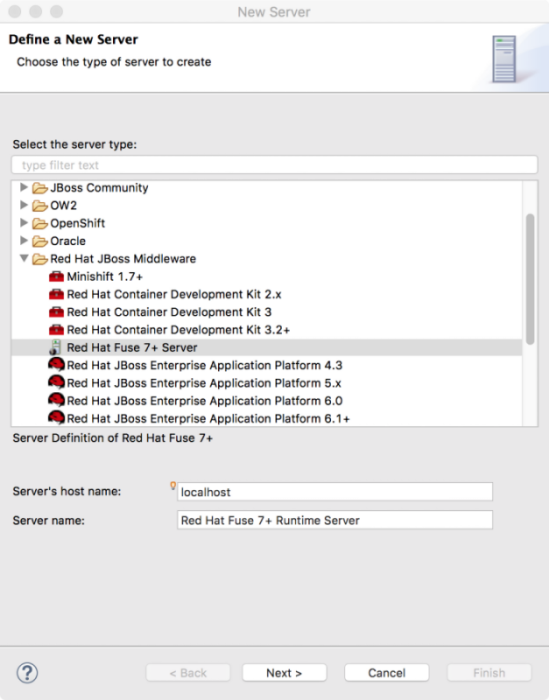
- Click the server that you want to add.
In the Server’s host name field, accept the default (
localhost).NoteThe address of
localhostis0.0.0.0.- In the Server name field, accept the default, or enter a different name for the runtime server.
For Server runtime environment, accept the default or click Add to open the server’s runtime definition page:
 Note
NoteIf the server is not already installed on your machine, you can install it now by clicking Download and install runtime… and following the site’s download instructions. Depending on the site, you might be required to provide valid credentials before you can continue the download process.
- Accept the default for the installation Name.
- In the Home Directory field, enter the path where the server runtime is installed, or click Browse to find and select it.
Next to Execution Environment, select the runtime JRE from the drop-down menu.
If the version you want does not appear in the list, click Environments and select the version from the list that appears. The JRE version you select must be installed on your machine.
NoteSee Red Hat Fuse Supported Configurations for the required Java version.
- Leave the Alternate JRE option as is.
Click Next to save the server’s runtime definition and open its Configuration details page:
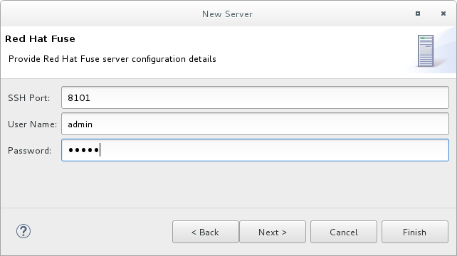
Accept the default for SSH Port (
8101).The runtime uses the SSH port to connect to the server’s Karaf shell. If this default is incorrect for your setup, you can discover the correct port number by looking in the server’s installDir
/etc/org.apache.karaf.shell.cfgfile.In the User Name field, enter the name used to log into the server.
For Red Hat Fuse, this is a user name stored in the Red Hat Fuse installDir
/etc/users.propertiesfile.NoteIf the default user has been activated (uncommented) in the
/etc/users.propertiesfile, the tooling autofills the User Name and Password fields with the default user’s name and password, as shown in [servCnfigDetails].If a user has not been set up, you can either add one to that file by using the format
user=password,role(for example,joe=secret,Administrator), or you can set one using the karafjaascommand set:-
jaas:realms— to list the realms -
jaas:manage --index 1— to edit the first (server) realm -
jaas:useradd <username> <password>— to add a user and associated password -
jaas:roleadd <username> Administrator— to specify the new user’s role -
jaas:update— to update the realm with the new user information
If a
jaasrealm has already been selected for the server, you can discover the user name by issuing the commandJBossFuse:karaf@root>jaas:users.-
- In the Password field, enter the password required for User Name to log into the server.
Click Finish to save the server’s configuration details.
The server runtime appears in the Servers view.
Expanding the server node exposes the server’s JMX node:

28.2. Starting a Server
Overview
When you start a configured server, the tooling opens the server’s remote management console in the Terminal view. This allows you to easily manage the container while testing your application.
Procedure
To start a server:
- In the Servers view, select the server you want to start.
Click
 .
.
The Console view opens and displays a message asking you to wait while the container is starting, for example:
 Note
NoteIf you did not properly configure the user name and password for opening the remote console, a dialog opens asking you to enter the proper credentials. See Section 28.1, “Adding a Server”.
- After the container has started up, the Terminal view opens to display the container’s management console.
The running server appears in the Servers view:

The running server also appears in the JMX Navigator view under Server Connections:
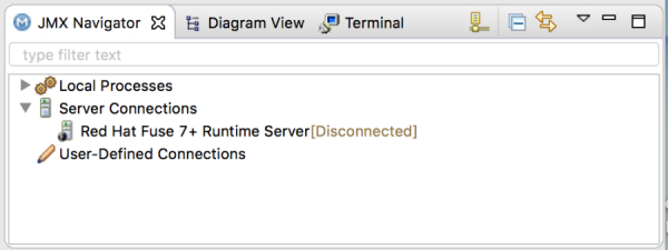 Note
NoteIf the server is running on the same machine as the tooling, the server also has an entry under Local Processes.
28.3. Connecting to a Running Server
Overview
After you start a configured server, it appears in the Servers view and in the JMX Navigator view under the Server Connections node. You may need to expand the Server Connections node to see the server.
To publish and test your Fuse project application on the running server, you must first connect to it. You can connect to a running server either in the Servers view or in the JMX Navigator view.
The Servers view and the JMX Navigator view are synchronized with regards to server connections. That is, connecting to a server in the Servers view also connects it in the JMX Navigator view, and vice versa.
Connecting to a running server in the Servers view
- In the Servers view, expand the server runtime to expose its JMX[Disconnected] node.
Double-click the JMX[Disconnected] node:

Viewing bundles installed on the connected server
- In either the Servers view or the JMX Navigator view, expand the server runtime tree to expose the Bundles node, and select it.
The tooling populates the Properties view with a list of bundles that are installed on the server:
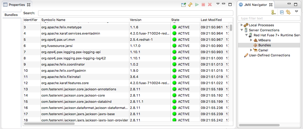
Using the Properties view’s Search tool, you can search for bundles by their Symbolic Name or by their Identifier, if you know it. As you type the symbolic name or the identifier, the list updates, showing only the bundles that match the current search string.
NoteAlternatively, you can issue the
osgi:listcommand in the Terminal view to see a generated list of bundles installed on the Red Hat Fuse server runtime. The tooling uses a different naming scheme for OSGi bundles displayed by theosgi:listcommand.In the
<build>section of project’spom.xmlfile, you can find the bundle’s symbolic name and its bundle name (OSGi) listed in themaven-bundle-pluginentry. For more details, see the section called “Verifying the project was published to the server”.
28.4. Disconnecting from a Server
Overview
When you are done testing your application, you can disconnect from the server without stopping it.
The Servers view and the JMX Navigator view are synchronized with regards to server connections. That is, disconnecting from a server in the Servers view also disconnects it in the JMX Navigator view, and vice versa.
Disconnecting from a server in the Servers view
- In the Servers view, expand the server runtime to expose its JMX[Connected] node.
Right-click the JMX[Connected] node to open the context menu, and then select Disconnect.
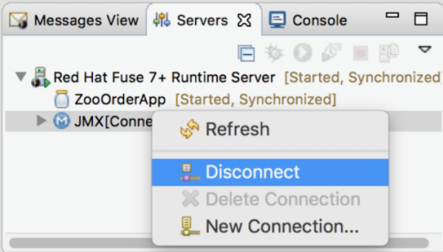
28.5. Stopping a Server
Overview
You can shut down a server in the Servers view or in the server’s remote console in the Terminal view.
Using the Servers view
To stop a server:
- In the Servers view, select the server you want to stop.
-
Click
 .
.
Using the remote console
To stop a server:
- Open the Terminal view that is hosting the server’s remote console.
- Press: CTRL+D
28.6. Deleting a Server
Overview
When you are finished with a configured server, or if you misconfigure a server, you can delete it and its configuration.
First, delete the server from the Servers view or from the JMX Navigator view. Next, delete the server’s configuration.
Deleting a server
- In the Servers view, right-click the server you want to delete to open the context menu.
- Select Delete.
- Click OK.
Deleting the server’s configuration
On the menu bar, select CodeReady Studio → Preferences → Server.
NoteOn Linux and Windows machines, select Window → Preferences.
- Expand the Server folder, and then select Runtime Environments to open the Server Runtime Environments page.
- From the list, select the runtime environment of the server that you previously deleted from the Servers view, and then click Remove.
- Click OK.
Chapter 29. Publishing Fuse Integration Projects to a Server
You deploy Fuse Integration projects into a server runtime using the Eclipse publishing mechanism. To do so, you must have defined and added the server to the Servers view in the Fuse Integration perspective. For a step-by-step demonstration, see .
Overview
You can set up supported servers to publish assigned Fuse projects automatically or to publish them only when you manually invoke the publish command.
Each server runtime added to the Servers view has its own Overview page that contains its configuration, connection, and publishing details:
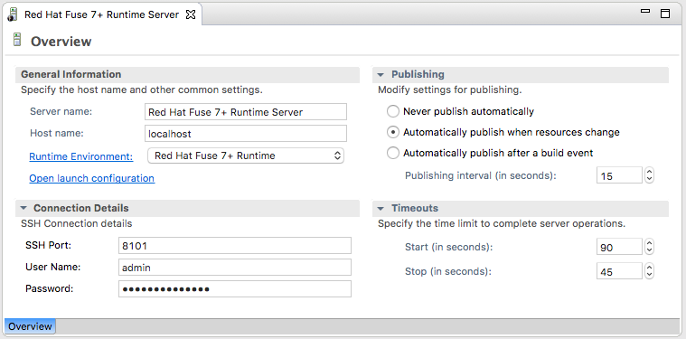
You might need to expand Publishing to expose the server runtime publishing options and default settings:
Never publish automatically — You must select this option to manually publish projects.
ImportantYou must also disable the If server started, publish changes immediately option on the server’s Add and Remove page (for details see, the section called “Publishing Fuse projects manually”.
- Automatically publish when resources change — [default] Enable this option to automatically publish or republish a Fuse project when you save changes made to it. How quickly projects are published depends on the Publishing interval (default is 15 seconds).
- Automatically publish after a build event — For Fuse projects, works the same as Automatically publish when resources change.
Publishing Fuse projects automatically when resources change
The default publishing option for server runtimes is Automatically publish when resources change.
- If necessary, start the server runtime to which you want to publish a Fuse project. For details, see Section 28.2, “Starting a Server”.
- In the Servers view, double-click the server runtime to open its Overview page.
- Expand Publishing, and then select Automatically publish when resources change.
- To increase or decrease the interval between publishing cycles, click the radio button next to Publishing interval (in seconds) up or down, as appropriate.
In the Servers view, right-click the server runtime to open the context menu, and then select Add and Remove.
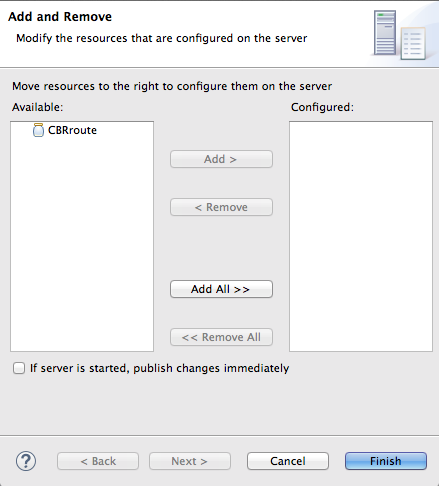
All resources available for publishing appear in the Available column.
To assign a resource (in this case, the CBRroute Fuse project) to the server runtime:
- Double-click it, or
Select it, and click Add.
The selected resource moves to the Configured column:
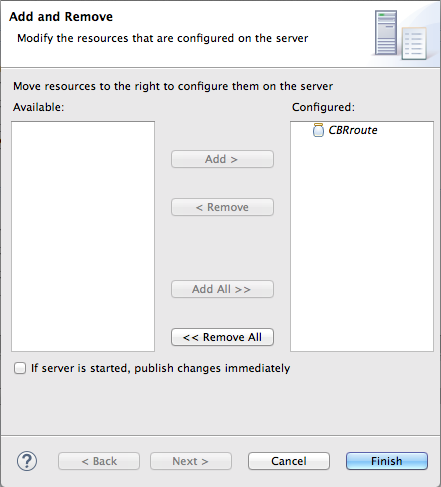
At this stage, the time at which the assigned resource would actually be published depends on whether the server runtime was running and on the Publishing interval setting. However, if the server was stopped, you would have to manually publish the project after you started the server (for details, see the section called “Publishing Fuse projects manually”).
Click the If server started, publish changes immediately option to enable it:

This option ensures that the configured project is published immediately once you click Finish. The Automatically publish when resources change option on the server runtime Overview page ensures that the configured project is republished whenever changes made to the local project are saved.
Click Finish.
The project appears in the Servers view under the server runtime node, and the server runtime status reports [Started,Publishing…].
When publishing is done, the status of both the server runtime and the project report is [Started,Synchronized]:
 Note
NoteFor a server runtime, Synchronized means that all published resources on the server are identical to their local counterparts. For a published resource, Synchronized means that it is identical to its local counterpart.
Publishing Fuse projects manually
- If necessary, start the server runtime to which you want to publish a Fuse project. For details, see Section 28.2, “Starting a Server”.
- In the Servers view, double-click the server runtime to open its Overview page.
- Expand Publishing, and then select Never publish automatically.
- Click File → Save to save the publishing option changes.
If the Fuse project has already been assigned to the server runtime, make sure this option is disabled: If server started, publish changes immediately:
- In the Servers view, right-click the server runtime to open the context menu.
- Click Add and Remove… to open the server’s Add and Remove page.
- If the following option is enabled, disable it: If server started, publish changes immediately.
- Skip to [finish].
If the Fuse project has not been assigned to the server runtime, assign it now:
- Follow [startAssignResource] through [stopAssignResource] in the section called “Publishing Fuse projects automatically when resources change”.
- Do not enable the If server started, publish changes immediately option.
Click Finish.
The project appears in the Servers view under the server runtime node, and the server runtime status reports [Started]:

In the Servers view, right-click the project’s node. In this example, select the CBRroute Fuse project to open the context menu:
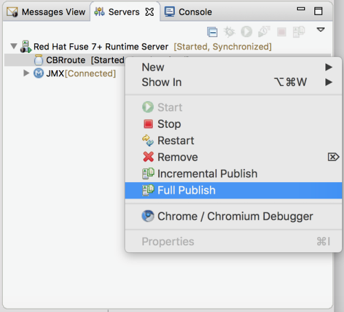
Select Full Publish.
During the publishing operation, the status of both the server runtime and the project report [Started,Republish].
When publishing is done, the status of both the server runtime and the project report [Started,Synchronized]:
NoteThe tooling does not support the Incremental Publish option. Clicking Incremental Publish results in a full publish.
Verifying the project was published to the server
After you have published a Fuse project to a server runtime, you can connect to the server and check that the project’s bundle was installed on it.
- Connect to the server runtime. For details see the section called “Connecting to a running server in the Servers view”.
In the Servers view, expand the server runtime tree to expose the Bundles node and select it.
The tooling populates the Properties view with a list of bundles that are installed on the server:
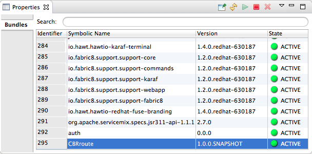
To find your project’s bundle, either scroll down to the bottom of the list, or start typing the bundle’s Symbolic Name in the Properties view’s Search box. The bundle’s Symbolic Name is the name you gave your project when you created it.
NoteAlternatively, you can issue the
osgi:listcommand in the Terminal view to see a generated list of bundles installed on the Fuse server runtime. The tooling uses a different naming scheme for OSGi bundles displayed by theosgi:listcommand.In the
<build>section of project’spom.xmlfile, you can find the bundle’s symbolic name and its bundle name (OSGi) listed in themaven-bundle-pluginentry; for example:
Appendix A. Fuse Integration Perspective
Use the Fuse Integration perspective to design, monitor, test, and publish your integration application.

You can open the Fuse Integration perspective in the following ways:
- When you create a new Fuse Integration project (see Chapter 1, Creating a New Fuse Integration Project), the tooling switches to the Fuse Integration perspective.
-
Click
 on the right side of the CodeReady Studio tool bar. If the
 icon is not available on the tool bar, click
 and then select Fuse Integration from the list of available perspectives.
- Select Window → Perspective → Open Perspective → Fuse Integration.
The Fuse Integration perspective consists of nine main areas:
Project Explorer view
Displays all projects known to the tooling. You can view all artifacts that make up each project. The Project Explorer view also displays all routing context
.xml. files for a project under itsCamel Contextsnode. This enables you to find and open a routing context file included in a project. Under each routing context.xmlfile, the Project Explorer view displays all routes defined within the context. For multiroute contexts, this lets you focus on a specific route on the canvas.
The route editor
Provides the main design-time tooling and consists of three tabs:
Design — Displays a large grid area on which routes are constructed and a palette from which Enterprise Integration Patterns (EIPs) and Camel components are selected and then connected on the canvas to form routes.

The canvas is the route editor’s workbench and where you do most of your work. It displays a graphical representation of one or more routes, which are made up of connected EIPs and Camel components (called nodes once they are placed on the canvas).
Selecting a node on the canvas populates the Properties view with the properties that apply to the selected node, so you can edit them.
The Palette contains all of the patterns and Camel components needed to construct a route and groups them according to function — Components, Routing, Control Flow, Transformation, and Miscellaneous.
Source
Displays the contents of the .xml file for the routes constructed on the route editor’s canvas.
You can edit the routing context in the Source tab as well as in the Design tab. The Source tab is useful for editing and adding any configuration, comments, or beans to the routing context file. The content assist feature helps you when working with configuration files. In the Source tab, press Ctrl+Space to see a list of possible values that can be inserted into your project.
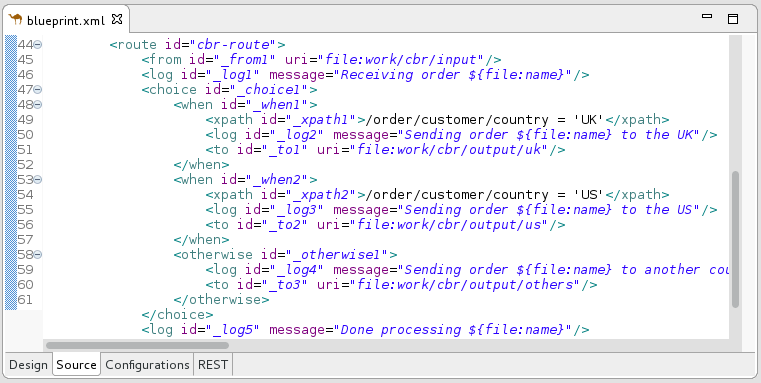
Configurations
Provides an easy way to add shared configuration (global endpoints, data formats, beans) to a multi-route routing context. For details see Section 2.6, “Adding global endpoints, data formats, or beans”.

REST
Provides a graphical representation of Rest DSL components.

Properties view
Displays the properties of the node selected on the canvas.
JMX Navigator view
Lists the JMX servers and the infrastructure they monitor. It enables you to browse JMX servers and the pocesses they are monitoring. It also identifies instances of Red Hat processes.
The JMX Navigator view drives all monitoring and testing activities in the Fuse Integration perspective. It determines which routes are displayed in the Diagram View, the Properties view, and the Messages View. It is also provides menu commands for activating route tracing, adding and deleting JMS destinations, and starting and suspending routes. It is also the target for dragging and dropping messages onto a route.
By default, the JMX Navigator view shows all Java processes that are running on your local machine. You can add JMX servers as needed to view infrastructure on other machines.
Diagram View
Displays a graphical tree representing the node selected in the JMX Navigator view. When you select a process, server, endpoint, or other node, the Diagram View shows the selected node as the root with branches down to its children and grandchildren.
When you select a broker, the Diagram View displays up to three children: connections, topics, and queues. It also shows configured connections and destinations as grandchildren.
When you select a route, the Diagram View displays all nodes in the route and shows the different paths that messages can take through the route. It also displays timing metrics for each processing step in the route when route tracing is enabled.
Messages View
Lists the messages that have passed through the selected JMS destination or through Apache Camel endpoints when route tracing is enabled.
When a JMS destination is selected in the JMX Navigator view, the view lists all messages that are at the destination.
When route tracing is enabled, the Messages View lists all messages that passed through the nodes in the route since tracing started. You can configure the Messages View to display only the data in which you are interested and in your preferred sequence.
When a message trace in the Messages View is selected, its details (message body and all message headers) appear in the Properties view. In the Diagram View, the step in the route associated with the selected message trace is highlighted.
Servers view
Displays a list of servers managed by the tooling. It displays their runtime status and provides controls for adding, starting and stopping them and for publishing projects to them.
Terminal view
Displays the command console of the connected container. You can control the container by entering commands in the Terminal view.
Console view
Displays the console output for recently executed actions.
Appendix B. Debug Perspective
Use the Debug perspective to monitor and debug a running Camel context.
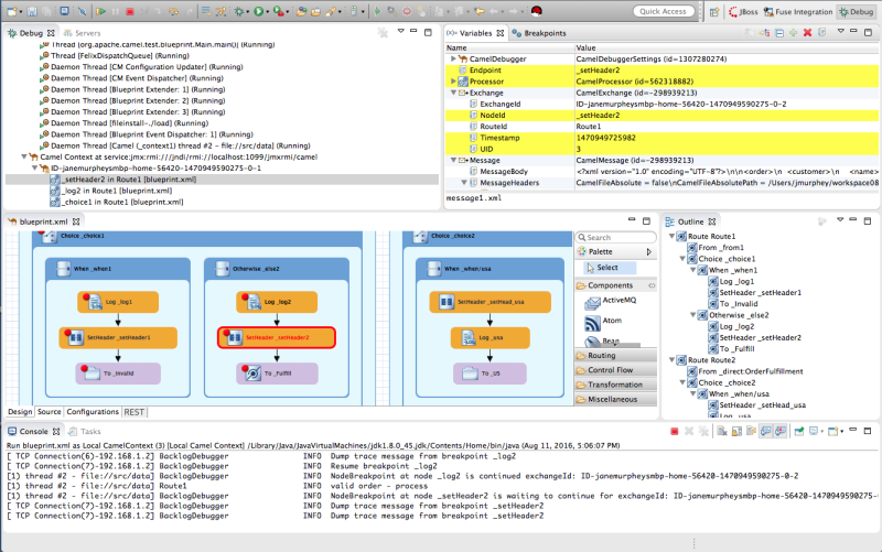
Debug view
For the running Camel context, the Debug view displays the debug stack.
You can switch between breakpoints within the same message flow, listed under the
Camel Context at service:jmx:rmi://jndi/rmi://localhost:1099/jmxrmi/camelentry, to review and compare variable values in the Variables view.Messages flows are identified by their unique breadcrumb ID, and the breadcrumb ID of each subsequent message flow is incremented by 2. For example, if the breadcrumb ID for the first message flow is
ID-janemurpheysmbp-home-54620-1470949590275-0-1, the breadcrumbID for the second message flow would beID-janemurpheysmbp-home-54620-1470949590275-0-3.Variables view
For each node in the routing context that has a breakpoint set, the Variables view displays the value of the available variables when the breakpoint is hit. Each variable who’s value changed since the preceding breakpoint is highlighted in yellow.
You can change the value of editable variables to check whether such changes produce the expected results and to test the robustness of your routing context.
You can also add variables to the watch list, so you can quickly and easily see whether their values change as expected at the expected point in the message flow.
Breakpoints view
Displays a list of the breakpoints set in the routing context, and shows whether they are enabled or disabled. You can enable and disable individual breakpoints by checking (enabling) or unchecking (disabling) them. This enables you to temporarily focus on nodes in your routing context that are behaving problematically.
The
 button skips over disabled breakpoints to jump to the next active breakpoint in the routing context. In contrast, the
 button jumps to the next node of execution in the routing context, regardless of breakpoints.
camel Context.xml view
Displays the running routing context file in graphical mode. For nodes set with breakpoints, it shows the type of breakpoint set and whether the breakpoint is enabled or disabled. When a breakpoint is hit, its corresponding node on the canvas is outlined in red.
To check a node’s configuration, open the Properties view and then select the node on the canvas in
camel Context.xml.Console view
Displays the log output generated by the Camel debugger as it executes the routing context.
Properties view
Displays the properties set for the node selected on the canvas in
CamelContext.xml.
