Questo contenuto non è disponibile nella lingua selezionata.
Drools Tools Reference Guide
JBoss Enterprise SOA Platform 5
This guide is for developers
Edition 5.3.1
Abstract
This guide teaches developers to use JBDS' Drools Tools plug-in.
Preface
Chapter 1. Preface
Copia collegamentoCollegamento copiato negli appunti!
1.1. Business Integration
Copia collegamentoCollegamento copiato negli appunti!
In order to provide a dynamic and competitive business infrastructure, it is crucial to have a service-oriented architecture in place that enables your disparate applications and data sources to communicate with each other with minimum overhead.
The JBoss Enterprise SOA Platform is a framework capable of orchestrating business services without the need to constantly reprogram them to fit changes in business processes. By using its business rules and message transformation and routing capabilities, JBoss Enterprise SOA Platform enables you to manipulate business data from multiple sources.
1.2. What is a Service-Oriented Architecture?
Copia collegamentoCollegamento copiato negli appunti!
Introduction
A Service Oriented Architecture (SOA) is not a single program or technology. Think of it, rather, as a software design paradigm.
As you may already know, a hardware bus is a physical connector that ties together multiple systems and subsystems. If you use one, instead of having a large number of point-to-point connectors between pairs of systems, you can simply connect each system to the central bus. An enterprise service bus (ESB) does exactly the same thing in software.
The ESB sits in the architectural layer above a messaging system. This messaging system facilitates asynchronous communications between services through the ESB. In fact, when you are using an ESB, everything is, conceptually, either a service (which, in this context, is your application software) or a message being sent between services. The services are listed as connection addresses (known as end-points references.)
It is important to note that, in this context, a "service" is not necessarily always a web service. Other types of applications, using such transports as File Transfer Protocol and the Java Message Service, can also be "services."
Note
At this point, you may be wondering if an enterprise service bus is the same thing as a service-oriented architecture. The answer is, "Not exactly." An ESB does not form a service-oriented architecture of itself. Rather, it provides many of the tools than can be used to build one. In particular, it facilitates the loose-coupling and asynchronous message passing needed by a SOA. Always think of a SOA as being more than just software: it is a series of principles, patterns and best practices.
1.3. Key Points of a Service-Oriented Architecture
Copia collegamentoCollegamento copiato negli appunti!
These are the key components of a service-oriented architecture:
- the messages being exchanged
- the agents that act as service requesters and providers
- the shared transport mechanisms that allow the messages to flow back and forth.
1.4. What is the JBoss Enterprise SOA Platform?
Copia collegamentoCollegamento copiato negli appunti!
The JBoss Enterprise SOA Platform is a framework for developing enterprise application integration (EAI) and service-oriented architecture (SOA) solutions. It is made up of an enterprise service bus (JBoss ESB) and some business process automation infrastructure. It allows you to build, deploy, integrate and orchestrate business services.
1.5. The Service-Oriented Architecture Paradigm
Copia collegamentoCollegamento copiato negli appunti!
The service-oriented architecture (SOA) consists of three roles: requester, provider, and broker.
- Service Provider
- A service provider allows access to services, creates a description of a service and publishes it to the service broker.
- Service Requester
- A service requester is responsible for discovering a service by searching through the service descriptions given by the service broker. A requester is also responsible for binding to services provided by the service provider.
- Service Broker
- A service broker hosts a registry of service descriptions. It is responsible for linking a requester to a service provider.
1.6. Core and Components
Copia collegamentoCollegamento copiato negli appunti!
The JBoss Enterprise SOA Platform provides a comprehensive server for your data integration needs. On a basic level, it is capable of updating business rules and routing messages through an Enterprise Service Bus.
The heart of the JBoss Enterprise SOA Platform is the Enterprise Service Bus. JBoss (ESB) creates an environment for sending and receiving messages. It is able to apply “actions” to messages to transform them and route them between services.
There are a number of components that make up the JBoss Enterprise SOA Platform. Along with the ESB, there is a registry (jUDDI), transformation engine (Smooks), message queue (HornetQ) and BPEL engine (Riftsaw).
1.7. Components of the JBoss Enterprise SOA Platform
Copia collegamentoCollegamento copiato negli appunti!
- A full Java EE-compliant application server (the JBoss Enterprise Application Platform)
- an enterprise service bus (JBoss ESB)
- a business process management system (jBPM)
- a business rules engine (JBoss Rules)
- support for the optional JBoss Enterprise Data Services (EDS) product.
1.8. JBoss Enterprise SOA Platform Features
Copia collegamentoCollegamento copiato negli appunti!
- The JBoss Enterprise Service Bus (ESB)
- The ESB sends messages between services and transforms them so that they can be processed by different types of systems.
- Business Process Execution Language (BPEL)
- You can use web services to orchestrate business rules using this language. It is included with SOA for the simple execution of business process instructions.
- Java Universal Description, Discovery and Integration (jUDDI)
- This is the default service registry in SOA. It is where all the information pertaining to services on the ESB are stored.
- Smooks
- This transformation engine can be used in conjunction with SOA to process messages. It can also be used to split messages and send them to the correct destination.
- JBoss Rules
- This is the rules engine that is packaged with SOA. It can infer data from the messages it receives to determine which actions need to be performed.
1.9. Features of the JBoss Enterprise SOA Platform's JBossESB Component
Copia collegamentoCollegamento copiato negli appunti!
The JBoss Enterprise SOA Platform's JBossESB component supports:
- Multiple transports and protocols
- A listener-action model (so that you can loosely-couple services together)
- Content-based routing (through the JBoss Rules engine, XPath, Regex and Smooks)
- Integration with the JBoss Business Process Manager (jBPM) in order to provide service orchestration functionality
- Integration with JBoss Rules in order to provide business rules development functionality.
- Integration with a BPEL engine.
Furthermore, the ESB allows you to integrate legacy systems in new deployments and have them communicate either synchronously or asynchronously.
In addition, the enterprise service bus provides an infrastructure and set of tools that can:
- Be configured to work with a wide variety of transport mechanisms (such as e-mail and JMS),
- Be used as a general-purpose object repository,
- Allow you to implement pluggable data transformation mechanisms,
- Support logging of interactions.
Important
There are two trees within the source code:
org.jboss.internal.soa.esb and org.jboss.soa.esb. Use the contents of the org.jboss.internal.soa.esb package sparingly because they are subject to change without notice. By contrast, everything within the org.jboss.soa.esb package is covered by Red Hat's deprecation policy.
1.10. Task Management
Copia collegamentoCollegamento copiato negli appunti!
JBoss SOA simplifies tasks by designating tasks to be performed universally across all systems it affects. This means that the user does not have to configure the task to run separately on each terminal. Users can connect systems easily by using web services.
Businesses can save time and money by using JBoss SOA to delegate their transactions once across their networks instead of multiple times for each machine. This also decreases the chance of errors ocurring.
1.11. Integration Use Case
Copia collegamentoCollegamento copiato negli appunti!
Acme Equity is a large financial service. The company possesses many databases and systems. Some are older, COBOL-based legacy systems and some are databases obtained through the acquisition of smaller companies in recent years. It is challenging and expensive to integrate these databases as business rules frequently change. The company wants to develop a new series of client-facing e-commerce websites, but these may not synchronise well with the existing systems as they currently stand.
The company wants an inexpensive solution but one that will adhere to the strict regulations and security requirements of the financial sector. What the company does not want to do is to have to write and maintain “glue code” to connect their legacy databases and systems.
The JBoss Enterprise SOA Platform was selected as a middleware layer to integrate these legacy systems with the new customer websites. It provides a bridge between front-end and back-end systems. Business rules implemented with the JBoss Enterprise SOA Platform can be updated quickly and easily.
As a result, older systems can now synchronise with newer ones due to the unifying methods of SOA. There are no bottlenecks, even with tens of thousands of transactions per month. Various integration types, such as XML, JMS and FTP, are used to move data between systems. Any one of a number of enterprise-standard messaging systems can be plugged into JBoss Enterprise SOA Platform providing further flexibility.
An additional benefit is that the system can now be scaled upwards easily as more servers and databases are added to the existing infrastructure.
1.12. Utilising the JBoss Enterprise SOA Platform in a Business Environment
Copia collegamentoCollegamento copiato negli appunti!
Cost reduction can be achieved due to the implementation of services that can quickly communicate with each other with less chance of error messages occurring. Through enhanced productivity and sourcing options, ongoing costs can be reduced.
Information and business processes can be shared faster because of the increased connectivity. This is enhanced by web services, which can be used to connect clients easily.
Legacy systems can be used in conjunction with the web services to allow different systems to "speak" the same language. This reduces the amount of upgrades and custom code required to make systems synchronise.
Chapter 2. Introduction
Copia collegamentoCollegamento copiato negli appunti!
2.1. Intended Audience
Copia collegamentoCollegamento copiato negli appunti!
This book is aimed at system administrators who wish to learn how to utilize the Drools Rules on their setup. It explains how to use the Drools Tools for creating, executing and debugging Drools processes and rules.
2.2. Aim of the Guide
Copia collegamentoCollegamento copiato negli appunti!
This guide aims to give users an overview of how to perform both basic and complex tasks using the Drools Rules package. It gives details on how to create Drools projects and debug rules. There is also information about editors, how to use them and what tasks they perform.
Chapter 3. Creating a New Drools Project
Copia collegamentoCollegamento copiato negli appunti!
3.1. Creating a Sample Drools Project
Copia collegamentoCollegamento copiato negli appunti!
- To create a new Drools project, click → → → → . This will open the New Drools Project wizard.Type the project name into the relevant field and click the button.
- You will see a list of default artifacts to it like sample rules, decision tables or ruleflows and Java classes for them. Add the ones that are relevant to your project and click .
- You will be asked to specify a Drools runtime. If you have not yet set it up, you should do this now by clicking the link.You should see the Preferences window where you can configure the workspace settings for Drools runtimes. To create a new runtime, click the button. It will prompt you to enter a name for a new runtime and a path to the Drools runtime on your file system.
Note
A Drools runtime is a collection of .jars on your file system that represent one specific release of the Drools project .jars. When creating a new runtime, you must either point to the release of your choice or create a new runtime on your file system from the .jars included in the Drools Eclipse plugin. - You can create a new Drools 5 runtime from the .jars embedded in the Drools Eclipse plugin. Click the button, select the folder where you want the runtime to be created and click .
- You will see the newly created runtime show up in your list of Drools runtimes. Check it and click the button.
- Click the to complete the project creation.
- Now you have a basic structure, classpath, sample rules and test case to get you started.
3.2. Drools Project Structure Overview
Copia collegamentoCollegamento copiato negli appunti!
Newly created projects contain an example rule file
Sample.drl in the src/main/rules directory and an example java file DroolsTest.java. These can be used to execute the rules in a Drools engine in the folder src/main/java , in the com.sample package. All the others .jar's that are necessary during execution are also added to the classpath in a custom classpath container called Drools Library .
Note
Rules do not have to be kept in Java projects at all, this is just a convenience for people who are already using Eclipse as their Java IDE.
3.3. Creating a New Rule
Copia collegamentoCollegamento copiato negli appunti!
- To create a new project you can either create an empty text
.drlfile or utilize the New Rule Package wizard. - To open the wizard select → → or use the menu with the JBoss Drools icon on the toolbar.
- On the wizard page, select rules as a top level directory to store your rules and enter a rule name. Next, specify the mandatory rule package name. This defines a namespace that groups rules together.
- The wizard then generates a rule skeleton to get you started.
Chapter 4. Debugging Rules
Copia collegamentoCollegamento copiato negli appunti!
4.1. Breakpoints
Copia collegamentoCollegamento copiato negli appunti!
Whenever the execution of rules runs into a breakpoint, the execution is halted. Once the execution stops, you can inspect the variables known at that point and use any of the default debugging actions to decide what should happen next (step over, continue, etc). The Debug view can be used to inspect the content of the working memory and agenda.
4.2. Creating Breakpoints
Copia collegamentoCollegamento copiato negli appunti!
- To create breakpoints in the Package Explorer view or Navigator view of the Drools perspective, double-click the selected
.drlfile to open it in the editor. - You can add and remove rule breakpoints in the
.drlfiles in two ways:- Double-click the rule in the Rule editor at the line where you want to add a breakpoint. A breakpoint can be removed by double-clicking the rule once more.
Note
Note that rule breakpoints can only be created in the consequence of a rule. Double-clicking on a line where no breakpoint is allowed will do nothing. - Right-click the ruler. Select the action in the context menu. Choosing this action will add a breakpoint at the selected line or remove it if there is one already.
- The Debug perspective contains a Breakpoints view which can be used to see all defined breakpoints, get their properties, enable/disable and remove them. You can switch to it by clicking → → → .
4.3. Debugging
Copia collegamentoCollegamento copiato negli appunti!
- Drools breakpoints are only enabled if you debug your application as a Drools Application. To do this you should perform one of two actions:
- Select the main class of your application. Right-click on it and select → .
- Alternatively, select → to open a new dialog window for creating, managing and running debug configurations.Select the Drools Application item in the left tree and click the button (leftmost icon in the toolbar above the tree). This will create a new configuration with a number of the properties already filled in based on main class you selected in the beginning. All properties shown here are the same as any standard Java program.
Note
Remember to change the name of your debug configuration to something meaningful. - Click the button on the bottom to start debugging your application.
- After enabling the debugging, the application starts executing and will halt if any breakpoint is encountered. This can be a Drools rule breakpoint, or any other standard Java breakpoint. Whenever a Drools rule breakpoint is encountered, the corresponding
.drlfile is opened and the active line is highlighted. The Variables view also contains all rule parameters and their value. You can then use the default Java debug actions to decide what to do next (resume, terminate, step over, etc). The debug views can also be used to determine the contents of the working memory and agenda at that time as well (the current executing working memory is automatically shown).
Chapter 5. Editors
Copia collegamentoCollegamento copiato negli appunti!
5.1. DSL
Copia collegamentoCollegamento copiato negli appunti!
A domain-specific language (DSL) is a set of custom rules, that is created specifically to solve problems in a particular domain and is not intended to be able to solve problems outside it. A DSL's configuration is stored in plain text.
5.2. DSL Editor
Copia collegamentoCollegamento copiato negli appunti!
- In Drools, the DSL configuration is stored in
.dslfiles. These can be created selecting → → → → from the projects context menu.Figure 5.1. The DSL editor
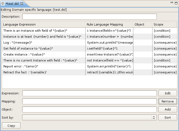
5.3. DSL Editor Components
Copia collegamentoCollegamento copiato negli appunti!
| Components | Description |
|---|---|
| Description | User's comments on a certain language message mapping. |
| Table of language message mappings | The table is divided into 4 rows:
|
| Expression | Shows the language expression of the selected table line (language message mapping). |
| Mapping | Shows the rule of language mapping for the selected table line (language message mapping). |
| Object | Shows the object for the selected table line (language message mapping). |
| Sort By | This option allows you to change the sorting order of the language message mappings. To do this select from the drop down list the method of sorting you want and click the button. |
| Buttons |
|
5.4. Edit the Language Mapping Wizard
Copia collegamentoCollegamento copiato negli appunti!
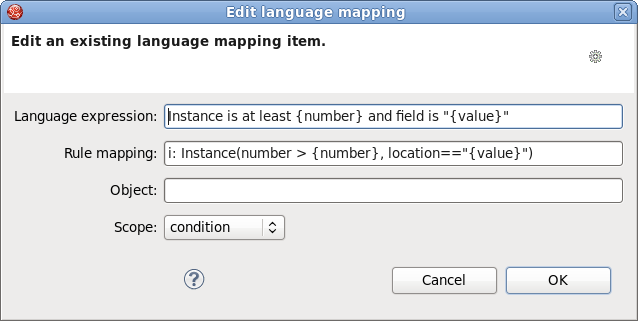
- This wizard can be opened by double clicking some line in the table of language message mappings or by clicking the button. You can edit the language expressions, rule mapping, objects and scopes of instance.
Figure 5.2. Editing options
- To change the mapping a user should edit the appropriate options and finally click the button.
5.5. Add a Language Mapping Wizard
Copia collegamentoCollegamento copiato negli appunti!
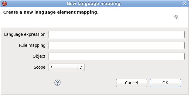
Procedure 5.1. Task
- Click on the button and a dialog box will appear.
- Enter the details of your language mapping wizard into the relevant fields.
Figure 5.3. Dialog box
5.6. Drools Flow Editor
Copia collegamentoCollegamento copiato negli appunti!
- Ruleflows can only be set by using the graphical flow editor which is part of the Drools plugin for Eclipse. Once you have set up a Drools project, you can start adding ruleflows. Add a ruleflow file (.rf) by clicking on the project and selecting → → → .By default these ruleflow files (.rf) are opened in the graphical Flow editor.
- The Flow editor consists of a palette, a canvas and an outline view. Select the element you would like to create in the palette and then add it to the canvas by clicking on the preferred location.
- Clicking on the Select option in the palette and then on the element in your ruleflow allows you to view and set the properties of that element in the Properties view.
- The Outline view is useful for complex schemata where not all nodes are seen at one time. Using the Outline view allows you to easily navigate between parts of a schema.
5.7. Different Types of Control Elements in Flow Palette
Copia collegamentoCollegamento copiato negli appunti!
| Icon | Name | Description |
|---|---|---|
| Select | Select a node on the canvas. | |
| Marquee | Selects a group of elements. | |
| Sequence flow | Joins two elements on the canvas |


5.8. Different Types of Nodes in Flow Palette
Copia collegamentoCollegamento copiato negli appunti!
| Icon | Name | Description |
|---|---|---|
| Start Event | The start of the ruleflow. There can only have one start node. The Start Event cannot have incoming connections and should have one outgoing connection. Whenever the ruleflow process is started, the execution is started here and is automatically forwarded to the first node linked to this Start Event. | |
| End Event | A ruleflow file can have multiple End Events. This node should have one incoming connection and no outgoing connections. When an end node is reached in the ruleflow, the ruleflow is terminated (including other remaining active nodes when parallelism is used). | |
| Rule Task | Represents a set of rules. A Rule Task node should have one incoming connection and one outgoing connection. The RuleFlowGroup property is used to specify the name of the ruleflow-group representing the set of rules. When a Rule Task node is reached in the ruleflow, the engine will start executing rules that are part of the corresponding ruleflow-group. Execution automatically continues to the next node when there are no more active rules in this ruleflow-group. | |
| Gateway[diverge] | Allows you to create branches in your ruleflow. A Gateway[diverge] node should have one incoming connection and two or more outgoing connections. | |
| Gateway[converge] | Allows you to synchronize multiple branches. A Gateway[converge] node should have two or more incoming connections and one outgoing connection. | |
| Reusable Sub-Process | Represents the invocation of another ruleflow from this ruleflow. A subflow node should have one incoming connection and one outgoing connection. It contains the property processId which specifies the ID of the process that should be executed. When a Reusable Sub-Process node is reached in the ruleflow, the engine will start the process with the given ID. The subflow node will only continue if the other subflow process has terminated its execution. The subflow process is started as an independent process, which means that the subflow process will not be terminated if this process reaches an end node. | |
| Script Task | Represents an action that should be executed in this ruleflow. A Script Task node should have one incoming connection and one outgoing connection. It contains the property "action" which specifies the action that should be executed. When a Script Task node is reached in the ruleflow, it will execute the action and continue with the next node. An action should be specified as a piece of (valid) MVEL code. |


5.9. Rule Editor
Copia collegamentoCollegamento copiato negli appunti!
The Rule editor works on files that have a
.drl (or .rule in the case of spreading rules across multiple rule files) extension. The editor follows the pattern of a normal text editor in Eclipse, with all the normal features of a text editor.
5.10. Content Assist
Copia collegamentoCollegamento copiato negli appunti!
While working in the Rule editor you can get a content assistance the usual way by pressing
Ctrl+Space. Content Assist shows all possible keywords for the current cursor position. It also suggests all available fields in a message.
5.11. Code Folding
Copia collegamentoCollegamento copiato negli appunti!
Code Folding is used in the rule editor. It allows you to hide and show sections of a file use the icons with minus and plus on the left vertical line of the editor.
5.12. Synchronization with Outline View
Copia collegamentoCollegamento copiato negli appunti!
The Rule editor works in synchronization with the Outline view which shows the structure of rules, imports objects into the file and also performs file functions. The view is updated on save. It provides a quick way of navigating around rules by names in a file which may have hundreds of rules. The items are sorted alphabetically by default.
5.13. Rete Tree View
Copia collegamentoCollegamento copiato negli appunti!
The Rete Tree view shows you the current Rete Network for your
.drl file. Just click on the Rete Tree tab at the bottom of the Rule editor. Afterwards you can generate the current Rete Network visualization. You can push and pull the nodes to arrange your optimal network overview.
If you have a large number of nodes, you can select some of them with a frame and pull them together. You can zoom in and out the Rete tree in case not all nodes are shown in the current view. For this use the combobox or + and - icons on the toolbar.
Note
The Rete Tree view works only in Drools Rule Projects, where the Drools Builder is set in the project properties.
Appendix A. Revision History
Copia collegamentoCollegamento copiato negli appunti!
| Revision History | |||
|---|---|---|---|
| Revision 5.3.1-68.400 | 2013-10-31 | ||
| |||
| Revision 5.3.1-68 | Wed Feb 20 2013 | ||
| |||
Legal Notice
Copia collegamentoCollegamento copiato negli appunti!
Copyright © 2013 Red Hat, Inc..
This document is licensed by Red Hat under the Creative Commons Attribution-ShareAlike 3.0 Unported License. If you distribute this document, or a modified version of it, you must provide attribution to Red Hat, Inc. and provide a link to the original. If the document is modified, all Red Hat trademarks must be removed.
Red Hat, as the licensor of this document, waives the right to enforce, and agrees not to assert, Section 4d of CC-BY-SA to the fullest extent permitted by applicable law.
Red Hat, Red Hat Enterprise Linux, the Shadowman logo, JBoss, OpenShift, Fedora, the Infinity logo, and RHCE are trademarks of Red Hat, Inc., registered in the United States and other countries.
Linux® is the registered trademark of Linus Torvalds in the United States and other countries.
Java® is a registered trademark of Oracle and/or its affiliates.
XFS® is a trademark of Silicon Graphics International Corp. or its subsidiaries in the United States and/or other countries.
MySQL® is a registered trademark of MySQL AB in the United States, the European Union and other countries.
Node.js® is an official trademark of Joyent. Red Hat Software Collections is not formally related to or endorsed by the official Joyent Node.js open source or commercial project.
The OpenStack® Word Mark and OpenStack logo are either registered trademarks/service marks or trademarks/service marks of the OpenStack Foundation, in the United States and other countries and are used with the OpenStack Foundation's permission. We are not affiliated with, endorsed or sponsored by the OpenStack Foundation, or the OpenStack community.
All other trademarks are the property of their respective owners.