Questo contenuto non è disponibile nella lingua selezionata.
Spine Leaf Networking
Configure routed spine-leaf networks using Red Hat OpenStack Platform director
Abstract
Chapter 1. Introduction
This guide provides information of how to construct a spine-leaf network topology for your Red Hat OpenStack Platform environment. This includes a full end-to-end scenario and example files to help replicate a more extensive network topology within your own environment.
1.1. Spine-leaf networking
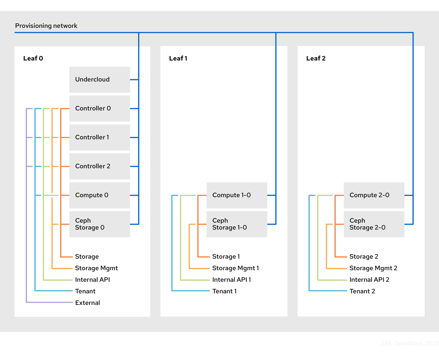
Red Hat OpenStack Platform’s composable network architecture allows you to adapt your networking to the popular routed spine-leaf data center topology. In a practical application of routed spine-leaf, a leaf is represented as a composable Compute or Storage role usually in a data center rack, as shown in Figure 1.1, “Routed spine-leaf example”. The Leaf 0 rack has an undercloud node, controllers, and compute nodes. The composable networks are presented to the nodes, which have been assigned to composable roles. In this diagram:
-
The
StorageLeafnetworks are presented to the Ceph storage and Compute nodes. -
The
NetworkLeafrepresents an example of any network you might want to compose.
Figure 1.1. Routed spine-leaf example

1.2. Network topology
The routed spine-leaf bare metal environment has one or more layer 3 capable switches, which route traffic between the isolated VLANs in the separate layer 2 broadcast domains.
The intention of this design is to isolate the traffic according to function. For example, if the controller nodes host an API on the Internal API network, when a compute node accesses the API it should use its own version of the Internal API network. For this routing to work, you need routes that force traffic destined for the Internal API network to use the required interface. This can be configured using supernet routes. For example, if you use 172.18.0.0/24 as the Internal API network for the controller nodes, you can use 172.18.1.0/24 for the second Internal API network, and 172.18.2.0/24 for the third, and so on. As a result, you can have a route pointing to the larger 172.18.0.0/16 supernet that uses the gateway IP on the local Internal API network for each role in each layer 2 domain.
This scenario uses the following networks:
| Network | Roles attached | Interface | Bridge | Subnet |
|---|---|---|---|---|
| Provisioning / Control Plane | All | nic1 | br-ctlplane (undercloud) | 192.168.10.0/24 |
| Storage | Controller | nic2 | 172.16.0.0/24 | |
| Storage Mgmt | Controller | nic3 | 172.17.0.0/24 | |
| Internal API | Controller | nic4 | 172.18.0.0/24 | |
| Tenant | Controller | nic5 | 172.19.0.0/24 | |
| External | Controller | nic6 | br-ex | 10.1.1.0/24 |
| Network | Roles attached | Interface | Bridge | Subnet |
|---|---|---|---|---|
| Provisioning / Control Plane | All | nic1 | br-ctlplane (undercloud) | 192.168.11.0/24 |
| Storage1 | Compute1, Ceph1 | nic2 | 172.16.1.0/24 | |
| Storage Mgmt1 | Ceph1 | nic3 | 172.17.1.0/24 | |
| Internal API1 | Compute1 | nic4 | 172.18.1.0/24 | |
| Tenant1 | Compute1 | nic5 | 172.19.1.0/24 |
| Network | Roles attached | Interface | Bridge | Subnet |
|---|---|---|---|---|
| Provisioning / Control Plane | All | nic1 | br-ctlplane (undercloud) | 192.168.12.0/24 |
| Storage2 | Compute2, Ceph2 | nic2 | 172.16.2.0/24 | |
| Storage Mgmt2 | Ceph2 | nic3 | 172.17.2.0/24 | |
| Internal API2 | Compute2 | nic4 | 172.18.2.0/24 | |
| Tenant2 | Compute2 | nic5 | 172.19.2.0/24 |
| Network | Subnet |
|---|---|
| Storage | 172.16.0.0/16 |
| Storage Mgmt | 172.17.0.0/16 |
| Internal API | 172.18.0.0/16 |
| Tenant | 172.19.0.0/16 |
1.3. Spine-leaf requirements
To deploy the overcloud on a network with a layer-3 routed architecture, you must meet the following requirements:
- Layer-3 routing
- The network infrastructure must have routing configured to enable traffic between the different layer-2 segments. This can be statically or dynamically configured.
- DHCP-Relay
-
Each layer-2 segment not local to the undercloud must provide
dhcp-relay. You must forward DHCP requests to the undercloud on the provisioning network segment where the undercloud is connected.
The undercloud uses two DHCP servers. One for baremetal node introspection, and another for deploying overcloud nodes. Make sure to read DHCP relay configuration to understand the requirements when configuring dhcp-relay.
1.4. Spine-leaf limitations
- Some roles, such as the Controller role, use virtual IP addresses and clustering. The mechanism behind this functionality requires layer-2 network connectivity between these nodes. These nodes are all be placed within the same leaf.
- Similar restrictions apply to Networker nodes. The network service implements highly-available default paths in the network using Virtual Router Redundancy Protocol (VRRP). Since VRRP uses a virtual router IP address, you must connect master and backup nodes to the same L2 network segment.
- When using tenant or provider networks with VLAN segmentation, you must share the particular VLANs between all Networker and Compute nodes.
It is possible to configure the network service with multiple sets of Networker nodes. Each set share routes for their networks, and VRRP would provide highly-available default paths within each set of Networker nodes. In such configuration all Networker nodes sharing networks must be on the same L2 network segment.
Chapter 2. Configuring the undercloud
This section describes a use case on how to configure the undercloud to accommodate routed spine-leaf with composable networks.
2.1. Configuring the spine leaf provisioning networks
To configure the provisioning networks for your spine leaf infrastructure, edit the undercloud.conf file and set the relevant parameters as defined in the following procedure.
Procedure
-
Log into the undercloud as the
stackuser. If you do not already have an
undercloud.conf, copy the sample template file:[stack@director ~]$ cp /usr/share/instack-undercloud/undercloud.conf.sample ~/undercloud.conf-
Edit your
undercloud.conf. In the
[DEFAULT]section:Set
local_ipto the undercloud IP onleaf0:local_ip = 192.168.10.1/24Set
undercloud_public_vipto the externally facing IP address of the undercloud:undercloud_public_vip = 10.1.1.1Set
undercloud_admin_vipto the administration IP address of the undercloud. This IP address is usually on leaf0:undercloud_admin_vip = 192.168.10.2Set
local_interfaceto the interface to bridge for the local network:local_interface = eth1Set
enable_routed_networkstotrue:enable_routed_networks = trueDefine your list of subnets using the
subnetsparameter. Define one subnet for each layer 2 segment in the routed spine and leaf:subnets = leaf0,leaf1,leaf2Specify the subnet associated with the physical layer 2 segment local to the undercloud using the
local_subnetparameter:local_subnet = leaf0
Create a new section per each subnet defined with the
subnetsparameter:[leaf0] cidr = 192.168.10.0/24 dhcp_start = 192.168.10.10 dhcp_end = 192.168.10.90 inspection_iprange = 192.168.10.100,192.168.10.190 gateway = 192.168.10.1 masquerade = False [leaf1] cidr = 192.168.11.0/24 dhcp_start = 192.168.11.10 dhcp_end = 192.168.11.90 inspection_iprange = 192.168.11.100,192.168.11.190 gateway = 192.168.11.1 masquerade = False [leaf2] cidr = 192.168.12.0/24 dhcp_start = 192.168.12.10 dhcp_end = 192.168.12.90 inspection_iprange = 192.168.12.100,192.168.12.190 gateway = 192.168.12.1 masquerade = False-
Save the
undercloud.conffile. Run the undercloud installation command:
[stack@director ~]$ openstack undercloud install
This creates three subnets on the provisioning network / control plane. The overcloud uses each network to provision systems within each respective leaf.
To ensure proper relay of DHCP requests to the undercloud, you might need to configure a DHCP relay. The next section provides some information on how to configure a DHCP relay.
2.2. Configuring a DHCP relay
The undercloud uses two DHCP servers on the provisioning network:
- one for introspection.
- one for provisioning.
When configuring a DHCP relay make sure to forward DHCP requests to both DHCP servers on the undercloud.
You can use UDP broadcast with devices that support it to relay DHCP requests to the L2 network segment where the undercloud provisioning network is connected. Alternatively you can use UDP unicast which relays DHCP requests to specific IP addresses.
Configuration of DHCP relay on specific devices types is beyond the scope of this document. As a reference, this document provides a DHCP relay configuration example using the implementation in ISC DHCP software is available below. Please refer to manual page dhcrelay(8) for further details on how to use this implementation.
Broadcast DHCP relay
This method relays DHCP requests using UDP broadcast traffic onto the L2 network segment where the DHCP server(s) resides. All devices on the network segment receive the broadcast traffic. When using UDP broadcast, both DHCP servers on the undercloud receive the relayed DHCP request. Depending on implementation this is typically configured by specifying either the interface or IP network address:
- Interface
- Specifying an interface connected to the L2 network segment where the DHCP requests are relayed.
- IP network address
- Specifying the network address of the IP network where the DHCP request are relayed.
Unicast DHCP relay
This method relays DHCP requests using UDP unicast traffic to specific DHCP servers. When using UDP unicast, you must configure the device providing DHCP relay to relay DHCP requests to both the IP address assigned to the interface used for introspection on the undercloud and the IP address of the network namespace created by the OpenStack Networking (neutron) service to host the DHCP service for the ctlplane network.
The interface used for introspection is the one defined as inspection_interface in undercloud.conf.
It is common to use the br-ctlplane interface for introspection. The IP address defined as local_ip in undercloud.conf is on the br-ctlplane interface.
The IP address allocated to the Neutron DHCP namespace is the first address available in the IP range configured for the local_subnet in undercloud.conf. The first address in the IP range is the one defined as dhcp_start in the configuration. For example: 192.168.10.10 would be the IP address when the following configuration is used:
[DEFAULT]
local_subnet = leaf0
subnets = leaf0,leaf1,leaf2

[leaf0]
cidr = 192.168.10.0/24
dhcp_start = 192.168.10.10
dhcp_end = 192.168.10.90
inspection_iprange = 192.168.10.100,192.168.10.190
gateway = 192.168.10.1
masquerade = FalseThe IP address for the DHCP namespace is automatically allocated. In most cases, it will be the first address in the IP range. Ensure sure to verify this is the case by running the following commands on the undercloud:
$ openstack port list --device-owner network:dhcp -c "Fixed IP Addresses"
+----------------------------------------------------------------------------+
| Fixed IP Addresses                                                         |
+----------------------------------------------------------------------------+
| ip_address='192.168.10.10', subnet_id='7526fbe3-f52a-4b39-a828-ec59f4ed12b2' |
+----------------------------------------------------------------------------+
$ openstack subnet show 7526fbe3-f52a-4b39-a828-ec59f4ed12b2 -c name
+-------+--------+
| Field | Value  |
+-------+--------+
| name  | leaf0  |
+-------+--------+
Example dhcrelay configuration
In the following example, the dhcrelay command in the dhcp package uses the following configuration:
-
Interfaces to relay incoming DHCP request:
eth1,eth2, andeth3. -
Interface the undercloud DHCP servers on the network segment are connected to:
eth0. - The DHCP server used for introspection is listening on IP address: `192.168.10.1.
-
The DHCP server used for provisioning is listening on IP address
192.168.10.10.
This results in the following dhcrelay command:
$ sudo dhcrelay -d --no-pid 172.20.0.10 172.20.0.1 \
  -i eth0 -i eth1 -i eth2 -i eth3
Example Cisco IOS routing switch configuration
This example uses the following Cisco IOS configuration to perform the following tasks:
- Configure a VLAN to use for our provisioning network.
- Add the the IP address of the leaf.
-
Forward UDP and BOOTP requests to the introspection DHCP server listening on IP address:
192.168.10.1. -
Forward UDP and BOOTP requests to the provisioning DHCP server listening on IP address
192.168.10.10.
interface vlan 2
ip address 192.168.24.254 255.255.255.0
ip helper-address 192.168.10.1
ip helper-address 192.168.10.10
!
Now that you have configured the provisioning network, you can configure the remaining overcloud leaf networks. You accomplish this with a series of configuration files.
2.3. Creating flavors and tagging nodes for leaf networks
Each role in each leaf network requires a flavor and role assignment so you can tag nodes into their respective leaf. This procedure shows how to create each flavor and assign them to a role.
Procedure
Source the
stackrcfile:$ source ~/stackrcCreate flavors for each custom role:
$ ROLES="control0 compute_leaf0 compute_leaf1 compute_leaf2 ceph-storage_leaf0 ceph-storage_leaf1 ceph-storage_leaf2"
$ for ROLE in $ROLES; do openstack flavor create --id auto --ram 4096 --disk 40 --vcpus 1 $ROLE ; done
$ for ROLE in $ROLES; do openstack flavor set --property "cpu_arch"="x86_64" --property "capabilities:boot_option"="local" --property "capabilities:profile"="$ROLE" $ROLE ; done
Tag nodes to their respective leaf networks. For example, run the following command to tag a node with UUID
58c3d07e-24f2-48a7-bbb6-6843f0e8ee13to the compute role on Leaf2:$ openstack baremetal node set --property capabilities='profile:compute_leaf2,boot_option:local' 58c3d07e-24f2-48a7-bbb6-6843f0e8ee13Create an environment file (
~/templates/node-data.yaml) that contains the mapping of flavors to roles:parameter_defaults: OvercloudController0Flavor: control0 Controller0Count: 3 OvercloudCompute0Flavor: compute_leaf0 Compute0Count: 3 OvercloudCompute1Flavor: compute_leaf1 Compute1Count: 3 OvercloudCompute2Flavor: compute_leaf2 Compute2Count: 3 OvercloudCephStorage0Flavor: ceph-storage_leaf0 CephStorage0Count: 3 OvercloudCephStorage1Flavor: ceph-storage_leaf1 CephStorage1Count: 3 OvercloudCephStorage2Flavor: ceph-storage_leaf2 CephStorage2Count: 3You can also set the number of nodes to deploy in the overcloud using each respective *Count` parameter.
2.4. Mapping bare metal node ports to control plane network segments
To enable deployment onto a L3 routed network the bare metal ports must have its physical_network field configured. Each baremetal port is associated with a bare metal node in the OpenStack Bare Metal (ironic) service. The physical network names are the ones used in the subnets option in the undercloud configuration.
The physical network name of the subnet specified as local_subnet in undercloud.conf is special. It is always named ctlplane.
Procedure
Source the
stackrcfile:$ source ~/stackrcCheck the bare metal nodes:
$ openstack baremetal node listEnsure the bare metal nodes are either in
enrollormanageablestate. If the bare metal node is not in one of these states, the command used to set the physical_network property on the baremetal port will fail. To set all nodes tomanageablestate run the following command:$ for node in $(openstack baremetal node list -f value -c Name); do openstack baremetal node manage $node --wait; doneCheck which baremetal ports are associated with which baremetal node. For example:
$ openstack baremetal port list --node <node-uuid>Set the
physical-networkparameter for the ports. In the example below, three subnets are defined in the configuration:leaf0,leaf1, andleaf2. The local_subnet isleaf0. Since the physical network for thelocal_subnetis alwaysctlplane, the baremetal port connected toleaf0uses ctlplane. The remaining ports use the other leaf names:$ openstack baremetal port set --physical-network ctlplane <port-uuid> $ openstack baremetal port set --physical-network leaf1 <port-uuid> $ openstack baremetal port set --physical-network leaf2 <port-uuid> $ openstack baremetal port set --physical-network leaf2 <port-uuid>Make sure the nodes are in available state before deploying the overcloud:
$ openstack overcloud node provide --all-manageable
Chapter 3. Alternative provisioning network methods
This section contains information about other methods to configure the provisioning network to accommodate routed spine-leaf with composable networks.
3.1. VLAN Provisioning Network
In this example, the director deploys new overcloud nodes through the provisioning network and uses a VLAN tunnel across the layer 3 topology (see Figure 3.1, “VLAN provisioning network topology”). This allows the director’s DHCP servers to send DHCPOFFER broadcasts to any leaf. To establish this tunnel, trunk a VLAN between the Top-of-Rack (ToR) leaf switches. In this diagram, the StorageLeaf networks are presented to the Ceph storage and Compute nodes; the NetworkLeaf represents an example of any network you may want to compose.
Figure 3.1. VLAN provisioning network topology

3.2. VXLAN Provisioning Network
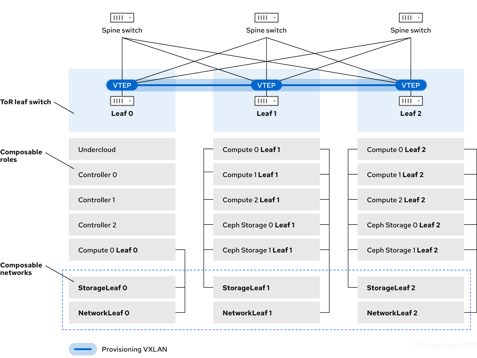
In this example, the director deploys new overcloud nodes through the provisioning network and uses a VXLAN tunnel to span across the layer 3 topology (see Figure 3.2, “VXLAN provisioning network topology”). This allows the director’s DHCP servers to send DHCPOFFER broadcasts to any leaf. To establish this tunnel, configure VXLAN endpoints on the Top-of-Rack (ToR) leaf switches.
Figure 3.2. VXLAN provisioning network topology
Chapter 4. Configuring the overcloud
Now that you have configured the undercloud, you can configure the remaining overcloud leaf networks. You accomplish this with a series of configuration files. Afterwards, you deploy the overcloud and the resulting deployment has multiple sets of networks with routing available.
4.1. Creating a network data file
To define the leaf networks, you create a network data file, which contain a YAML formatted list of each composable network and its attributes. The default network data is located on the undercloud at /usr/share/openstack-tripleo-heat-templates/network_data.yaml.
Procedure
Create a new
network_data_spine_leaf.yamlfile in yourstackuser’s local directory. Use the defaultnetwork_datafile as a basis:$ cp /usr/share/openstack-tripleo-heat-templates/network_data.yaml /home/stack/network_data_spine_leaf.yamlIn the
network_data_spine_leaf.yamlfile, create a YAML list to define each network and leaf network as a composable network item. For example, the Internal API network and its leaf networks are defined using the following syntax:# Internal API - name: InternalApi name_lower: internal_api vip: true ip_subnet: '172.18.0.0/24' allocation_pools: [{'start': '172.18.0.4', 'end': '172.18.0.250'}] - name: InternalApi1 name_lower: internal_api1 vip: false ip_subnet: '172.18.1.0/24' allocation_pools: [{'start': '172.18.1.4', 'end': '172.18.1.250'}] - name: InternalApi2 name_lower: internal_api2 vip: false ip_subnet: '172.18.2.0/24' allocation_pools: [{'start': '172.18.2.4', 'end': '172.18.2.250'}]
You do not define the Control Plane networks in the network data file since the undercloud has already created these networks. However, you need to manually set the parameters so that the overcloud can configure its NICs accordingly.
Define vip: true for the networks that contain the Controller-based services. In this example, InternalApi contains these services.
See Appendix A, Example network_data file for a full example with all composable networks.
4.2. Creating a roles data file
This section demonstrates how to define each composable role for each leaf and attach the composable networks to each respective role.
Procedure
Create a custom
rolesdirector in yourstackuser’s local directory:$ mkdir ~/rolesCopy the default Controller, Compute, and Ceph Storage roles from the director’s core template collection to the
~/rolesdirectory. Rename the files for Leaf 1:$ cp /usr/share/openstack-tripleo-heat-templates/roles/Controller.yaml ~/roles/Controller.yaml $ cp /usr/share/openstack-tripleo-heat-templates/roles/Compute.yaml ~/roles/Compute1.yaml $ cp /usr/share/openstack-tripleo-heat-templates/roles/CephStorage.yaml ~/roles/CephStorage1.yamlEdit the
Compute1.yamlfile:$ vi ~/roles/Compute1.yamlEdit the
name,networks, andHostnameFormatDefaultparameters in this file so that they align with the Leaf 1 specific parameters. For example:- name: Compute1 ... networks: - InternalApi1 - Tenant1 - Storage1 HostnameFormatDefault: '%stackname%-compute1-%index%'Save this file.
Edit the
CephStorage1.yamlfile:$ vi ~/roles/CephStorage1.yamlEdit the
nameandnetworksparameters in this file so that they align with the Leaf 1 specific parameters. In addition, add theHostnameFormatDefaultparameter and define the Leaf 1 hostname for our Ceph Storage nodes. For example:- name: CephStorage1 ... networks: - Storage1 - StorageMgmt1 HostnameFormatDefault: '%stackname%-cephstorage1-%index%'Save this file.
Copy the Leaf 1 Compute and Ceph Storage files as a basis for your Leaf 2 and Leaf 3 files:
$ cp ~/roles/Compute1.yaml ~/roles/Compute2.yaml $ cp ~/roles/Compute1.yaml ~/roles/Compute3.yaml $ cp ~/roles/CephStorage1.yaml ~/roles/CephStorage2.yaml $ cp ~/roles/CephStorage1.yaml ~/roles/CephStorage3.yamlEdit the
name,networks, andHostnameFormatDefaultparameters in the Leaf 2 and Leaf 3 files so that they align with the respective Leaf network parameters. For example, the parameters in the Leaf 2 Compute file have the following values:- name: Compute2 ... networks: - InternalApi2 - Tenant2 - Storage2 HostnameFormatDefault: '%stackname%-compute2-%index%'The Leaf 2 Ceph Storage parameters have the following values:
- name: CephStorage2 ... networks: - Storage2 - StorageMgmt2 HostnameFormatDefault: '%stackname%-cephstorage2-%index%'When your roles are ready, generate the full roles data file using the following command:
$ openstack overcloud roles generate --roles-path ~/roles -o roles_data_spine_leaf.yaml Controller Compute1 Compute2 Compute3 CephStorage1 CephStorage2 CephStorage3This creates a full
roles_data_spine_leaf.yamlfile that includes all the custom roles for each respective leaf network.
See Appendix C, Example roles_data file for a full example of this file.
Each role has its own NIC configuration. Before configuring the spine-leaf configuration, you need to create a base set of NIC templates to suit your current NIC configuration.
4.3. Creating a custom NIC Configuration
Each role requires its own NIC configuration. Create a copy of the base set of NIC templates and modify them to suit your current NIC configuration.
Procedure
Change to the core Heat template directory:
$ cd /usr/share/openstack-tripleo-heat-templatesRender the Jinja2 templates using the
tools/process-templates.pyscript, your customnetwork_datafile, and customroles_datafile:$ tools/process-templates.py -n /home/stack/network_data_spine_leaf.yaml \ -r /home/stack/roles_data_spine_leaf.yaml \ -o /home/stack/openstack-tripleo-heat-templates-spine-leafChange to the home directory:
$ cd /home/stackCopy the content from one of the default NIC templates to use as a basis for your spine-leaf templates. For example, copy the
single-nic-vlans:$ cp -r openstack-tripleo-heat-templates-spine-leaf/network/config/single-nic-vlans/* \ /home/stack/templates/spine-leaf-nics/.Remove the rendered template directory:
$ rm -rf openstack-tripleo-heat-templates-spine-leaf
Resources
- See "Custom Network Interface Templates" in the Advanced Overcloud Customization guide for more information on customizing your NIC templates.
4.4. Editing custom Controller NIC configuration
The rendered template contains most of the content that is necessary to suit the spine-leaf configuration. However, some additional configuration changes are required. Follow this procedure to modify the YAML structure for Controller nodes on Leaf0.
Procedure
Change to your custom NIC directory:
$ cd ~/templates/spine-leaf-nics/-
Edit the template for
controller0.yaml. Scroll to the
ControlPlaneSubnetCidrandControlPlaneDefaultRouteparameters in theparameterssection. These parameters resemble the following snippet:ControlPlaneSubnetCidr: # Override this via parameter_defaults default: '24' description: The subnet CIDR of the control plane network. type: string ControlPlaneDefaultRoute: # Override this via parameter_defaults description: The default route of the control plane network. type: stringModify these parameters to suit Leaf0:
ControlPlane0SubnetCidr: # Override this via parameter_defaults default: '24' description: The subnet CIDR of the control plane network. type: string ControlPlane0DefaultRoute: # Override this via parameter_defaults description: The default route of the control plane network. type: stringScroll to the
EC2MetadataIpparameter in theparameterssection. This parameter resembles the following snippet:EC2MetadataIp: # Override this via parameter_defaults description: The IP address of the EC2 metadata server. type: stringModify this parameter to suit Leaf0:
Leaf0EC2MetadataIp: # Override this via parameter_defaults description: The IP address of the EC2 metadata server. type: stringScroll to the network configuration section. This section looks like the following example:
resources: OsNetConfigImpl: type: OS::Heat::SoftwareConfig properties: group: script config: str_replace: template: get_file: ../../scripts/run-os-net-config.sh params: $network_config: network_config:Change the location of the script to the absolute path:
resources: OsNetConfigImpl: type: OS::Heat::SoftwareConfig properties: group: script config: str_replace: template: get_file: /usr/share/openstack-tripleo-heat-templates/network/scripts/run-os-net-config.sh params: $network_config: network_config:In the
network_configsection, define the control plane / provisioning interface. For example:network_config: - type: ovs_bridge name: bridge_name use_dhcp: false dns_servers: get_param: DnsServers addresses: - ip_netmask: list_join: - / - - get_param: ControlPlaneIp - get_param: ControlPlane0SubnetCidr routes: - ip_netmask: 169.254.169.254/32 next_hop: get_param: Leaf0EC2MetadataIp - ip_netmask: 192.168.10.0/24 next_hop: get_param: ControlPlane0DefaultRouteNote that the parameters used in this case are specific to Leaf0:
ControlPlane0SubnetCidr,Leaf0EC2MetadataIp, andControlPlane0DefaultRoute. Also note the use of the CIDR for Leaf0 on the provisioning network (192.168.10.0/24), which is used as a route.Each VLAN in the
memberssection contains the relevant Leaf0 parameters. For example, the Storage network VLAN information should appear similar to the following snippet:- type: vlan vlan_id: get_param: Storage0NetworkVlanID addresses: - ip_netmask: get_param: Storage0IpSubnetAdd a section to define parameters for routing. This includes the supernet route (
StorageSupernetin this case) and the leaf default route (Storage0InterfaceDefaultRoutein this case):- type: vlan vlan_id: get_param: Storage0NetworkVlanID addresses: - ip_netmask: get_param: Storage0IpSubnet routes: - ip_netmask: get_param: StorageSupernet next_hop: get_param: Storage0InterfaceDefaultRouteAdd the routes for the VLAN structure for the following Controller networks:
Storage,StorageMgmt,InternalApi, andTenant.- Save this file.
4.5. Creating custom Compute NIC configurations
This procedure creates a YAML structure for Compute nodes on Leaf0, Leaf1, and Leaf2.
Procedure
Change to your custom NIC directory:
$ cd ~/templates/spine-leaf-nics/-
Edit the template for
compute0.yaml. Scroll to the
ControlPlaneSubnetCidrandControlPlaneDefaultRouteparameters in theparameterssection. These parameters resemble the following snippet:ControlPlaneSubnetCidr: # Override this via parameter_defaults default: '24' description: The subnet CIDR of the control plane network. type: string ControlPlaneDefaultRoute: # Override this via parameter_defaults description: The default route of the control plane network. type: stringModify these parameters to suit Leaf0:
ControlPlane0SubnetCidr: # Override this via parameter_defaults default: '24' description: The subnet CIDR of the control plane network. type: string ControlPlane0DefaultRoute: # Override this via parameter_defaults description: The default route of the control plane network. type: stringScroll to the
EC2MetadataIpparameter in theparameterssection. This parameter resembles the following snippet:EC2MetadataIp: # Override this via parameter_defaults description: The IP address of the EC2 metadata server. type: stringModify this parameter to suit Leaf0:
Leaf0EC2MetadataIp: # Override this via parameter_defaults description: The IP address of the EC2 metadata server. type: stringScroll to the network configuration section. This section resembles the following snippet:
resources: OsNetConfigImpl: type: OS::Heat::SoftwareConfig properties: group: script config: str_replace: template: get_file: ../../scripts/run-os-net-config.sh params: $network_config: network_config:Change the location of the script to the absolute path:
resources: OsNetConfigImpl: type: OS::Heat::SoftwareConfig properties: group: script config: str_replace: template: get_file: /usr/share/openstack-tripleo-heat-templates/network/scripts/run-os-net-config.sh params: $network_config: network_config:In the
network_configsection, define the control plane / provisioning interface. For examplenetwork_config: - type: interface name: nic1 use_dhcp: false dns_servers: get_param: DnsServers addresses: - ip_netmask: list_join: - / - - get_param: ControlPlaneIp - get_param: ControlPlane0SubnetCidr routes: - ip_netmask: 169.254.169.254/32 next_hop: get_param: Leaf0EC2MetadataIp - ip_netmask: 192.168.10.0/24 next_hop: get_param: ControlPlane0DefaultRouteNote that the parameters used in this case are specific to Leaf0:
ControlPlane0SubnetCidr,Leaf0EC2MetadataIp, andControlPlane0DefaultRoute. Also note the use of the CIDR for Leaf0 on the provisioning network (192.168.10.0/24), which is used as a route.Each VLAN in the
memberssection should contain the relevant Leaf0 parameters. For example, the Storage network VLAN information should appear similar to the following snippet:- type: vlan vlan_id: get_param: Storage0NetworkVlanID addresses: - ip_netmask: get_param: Storage0IpSubnetAdd a section to define parameters for routing. This includes the supernet route (
StorageSupernetin this case) and the leaf default route (Storage0InterfaceDefaultRoutein this case):- type: vlan vlan_id: get_param: Storage0NetworkVlanID addresses: - ip_netmask: get_param: Storage0IpSubnet routes: - ip_netmask: get_param: StorageSupernet next_hop: get_param: Storage0InterfaceDefaultRouteAdd a VLAN structure for the following Controller networks:
Storage,InternalApi, andTenant.- Save this file.
Edit
compute1.yamland perform the same steps. The following is the list of changes:-
Change
ControlPlaneSubnetCidrtoControlPlane1SubnetCidr. -
Change
ControlPlaneDefaultRoutetoControlPlane1DefaultRoute. -
Change
EC2MetadataIptoLeaf1EC2MetadataIp. -
Change the network configuration script from
../../scripts/run-os-net-config.shto/usr/share/openstack-tripleo-heat-templates/network/scripts/run-os-net-config.sh. - Modifying the control plane / provisioning interface to use the Leaf1 parameters.
- Modifying each VLAN to include the Leaf1 routes.
Save this file when complete.
-
Change
Edit
compute2.yamland perform the same steps. The following is the list of changes:-
Change
ControlPlaneSubnetCidrtoControlPlane2SubnetCidr. -
Change
ControlPlaneDefaultRoutetoControlPlane2DefaultRoute. -
Change
EC2MetadataIptoLeaf2EC2MetadataIp. -
Change the network configuration script from
../../scripts/run-os-net-config.shto/usr/share/openstack-tripleo-heat-templates/network/scripts/run-os-net-config.sh. - Modify the control plane / provisioning interface to use the Leaf2 parameters.
- Modifying each VLAN to include the Leaf2 routes.
Save this file when complete.
-
Change
4.6. Creating custom Ceph Storage NIC configurations
This procedure creates a YAML structure for Ceph Storage nodes on Leaf0, Leaf1, and Leaf2.
Procedure
Change to your custom NIC directory:
$ cd ~/templates/spine-leaf-nics/Scroll to the
ControlPlaneSubnetCidrandControlPlaneDefaultRouteparameters in theparameterssection. These parameters resemble the following snippet:ControlPlaneSubnetCidr: # Override this via parameter_defaults default: '24' description: The subnet CIDR of the control plane network. type: string ControlPlaneDefaultRoute: # Override this via parameter_defaults description: The default route of the control plane network. type: stringModify these parameters to suit Leaf0:
ControlPlane0SubnetCidr: # Override this via parameter_defaults default: '24' description: The subnet CIDR of the control plane network. type: string ControlPlane0DefaultRoute: # Override this via parameter_defaults description: The default route of the control plane network. type: stringScroll to the
EC2MetadataIpparameter in theparameterssection. This parameter resembles the following snippet:EC2MetadataIp: # Override this via parameter_defaults description: The IP address of the EC2 metadata server. type: stringModify this parameter to suit Leaf0:
Leaf0EC2MetadataIp: # Override this via parameter_defaults description: The IP address of the EC2 metadata server. type: stringScroll to the network configuration section. This section resembles the following snippet:
resources: OsNetConfigImpl: type: OS::Heat::SoftwareConfig properties: group: script config: str_replace: template: get_file: ../../scripts/run-os-net-config.sh params: $network_config: network_config:Change the location of the script to the absolute path:
resources: OsNetConfigImpl: type: OS::Heat::SoftwareConfig properties: group: script config: str_replace: template: get_file: /usr/share/openstack-tripleo-heat-templates/network/scripts/run-os-net-config.sh params: $network_config: network_config:In the
network_configsection, define the control plane / provisioning interface. For examplenetwork_config: - type: interface name: nic1 use_dhcp: false dns_servers: get_param: DnsServers addresses: - ip_netmask: list_join: - / - - get_param: ControlPlaneIp - get_param: ControlPlane0SubnetCidr routes: - ip_netmask: 169.254.169.254/32 next_hop: get_param: Leaf0EC2MetadataIp - ip_netmask: 192.168.10.0/24 next_hop: get_param: ControlPlane0DefaultRouteNote that the parameters used in this case are specific to Leaf0:
ControlPlane0SubnetCidr,Leaf0EC2MetadataIp, andControlPlane0DefaultRoute. Also note the use of the CIDR for Leaf0 on the provisioning network (192.168.10.0/24), which is used as a route.Each VLAN in the
memberssection contains the relevant Leaf0 parameters.For example, the Storage network VLAN information should appear similar to the following snippet:- type: vlan vlan_id: get_param: Storage0NetworkVlanID addresses: - ip_netmask: get_param: Storage0IpSubnetAdd a section to define parameters for routing. This includes the supernet route (
StorageSupernetin this case) and the leaf default route (Storage0InterfaceDefaultRoutein this case):- type: vlan vlan_id: get_param: Storage0NetworkVlanID addresses: - ip_netmask: get_param: Storage0IpSubnet routes: - ip_netmask: get_param: StorageSupernet next_hop: get_param: Storage0InterfaceDefaultRouteAdd a VLAN structure for the following Controller networks:
Storage,StorageMgmt.- Save this file.
Edit
ceph-storage1.yamland perform the same steps. The following is the list of changes:-
Change
ControlPlaneSubnetCidrtoControlPlane1SubnetCidr. -
Change
ControlPlaneDefaultRoutetoControlPlane1DefaultRoute. -
Change
EC2MetadataIptoLeaf1EC2MetadataIp. -
Change the network configuration script from
../../scripts/run-os-net-config.shto/usr/share/openstack-tripleo-heat-templates/network/scripts/run-os-net-config.sh. - Modify the control plane / provisioning interface to use the Leaf1 parameters.
- Modify each VLAN to include the Leaf1 routes.
Save this file when complete.
-
Change
Edit
ceph-storage2.yamland perform the same steps. The following is the list of changes:-
Change
ControlPlaneSubnetCidrtoControlPlane2SubnetCidr. -
Change
ControlPlaneDefaultRoutetoControlPlane2DefaultRoute. -
Change
EC2MetadataIptoLeaf2EC2MetadataIp. -
Change the network configuration script from
../../scripts/run-os-net-config.shto/usr/share/openstack-tripleo-heat-templates/network/scripts/run-os-net-config.sh. - Modify the control plane / provisioning interface to use the Leaf2 parameters.
- Modify each VLAN to include the Leaf2 routes.
Save this file when complete.
-
Change
4.7. Creating a network environment file
This procedure creates a basic network environment file for use later.
Procedure
-
Create a
network-environment.yamlfile in your stack user’stemplatesdirectory. Add the following sections to the environment file:
resource_registry: parameter_defaults:Note the following:
-
The
resource_registrywill map networking resources to their respective NIC templates. -
The
parameter_defaultswill define additional networking parameters relevant to your configuration.
-
The
The next couple of sections add details to your network environment file to configure certain aspects of the spine leaf architecture. Once complete, you include this file with your openstack overcloud deploy command.
4.8. Mapping network resources to NIC templates
This procedure maps the relevant resources for network configurations to their respective NIC templates.
Procedure
-
Edit your
network-environment.yamlfile. Add the resource mappings to your
resource_registry. The resource names take the following format:OS::TripleO::[ROLE]::Net::SoftwareConfig: [NIC TEMPLATE]For this guide’s scenario, the
resource_registryincludes the following resource mappings:resource_registry: OS::TripleO::Controller0::Net::SoftwareConfig: ./spine-leaf-nics/controller0.yaml OS::TripleO::Compute0::Net::SoftwareConfig: ./spine-leaf-nics/compute0.yaml OS::TripleO::Compute1::Net::SoftwareConfig: ./spine-leaf-nics/compute1.yaml OS::TripleO::Compute2::Net::SoftwareConfig: ./spine-leaf-nics/compute2.yaml OS::TripleO::CephStorage0::Net::SoftwareConfig: ./spine-leaf-nics/cephstorage0.yaml OS::TripleO::CephStorage1::Net::SoftwareConfig: ./spine-leaf-nics/cephstorage1.yaml OS::TripleO::CephStorage2::Net::SoftwareConfig: ./spine-leaf-nics/cephstorage2.yaml-
Save the
network-environment.yamlfile.
4.9. Spine leaf routing
Each role requires routes on each isolated network, pointing to the other subnets used for the same function. So when a Compute1 node contacts a controller on the InternalApi VIP, the traffic should target the InternalApi1 interface through the InternalApi1 gateway. As a result, the return traffic from the controller to the InternalApi1 network should go through the InternalApi network gateway.
The supernet routes apply to all isolated networks on each role to avoid sending traffic through the default gateway, which by default is the Control Plane network on non-controllers, and the External network on the controllers.
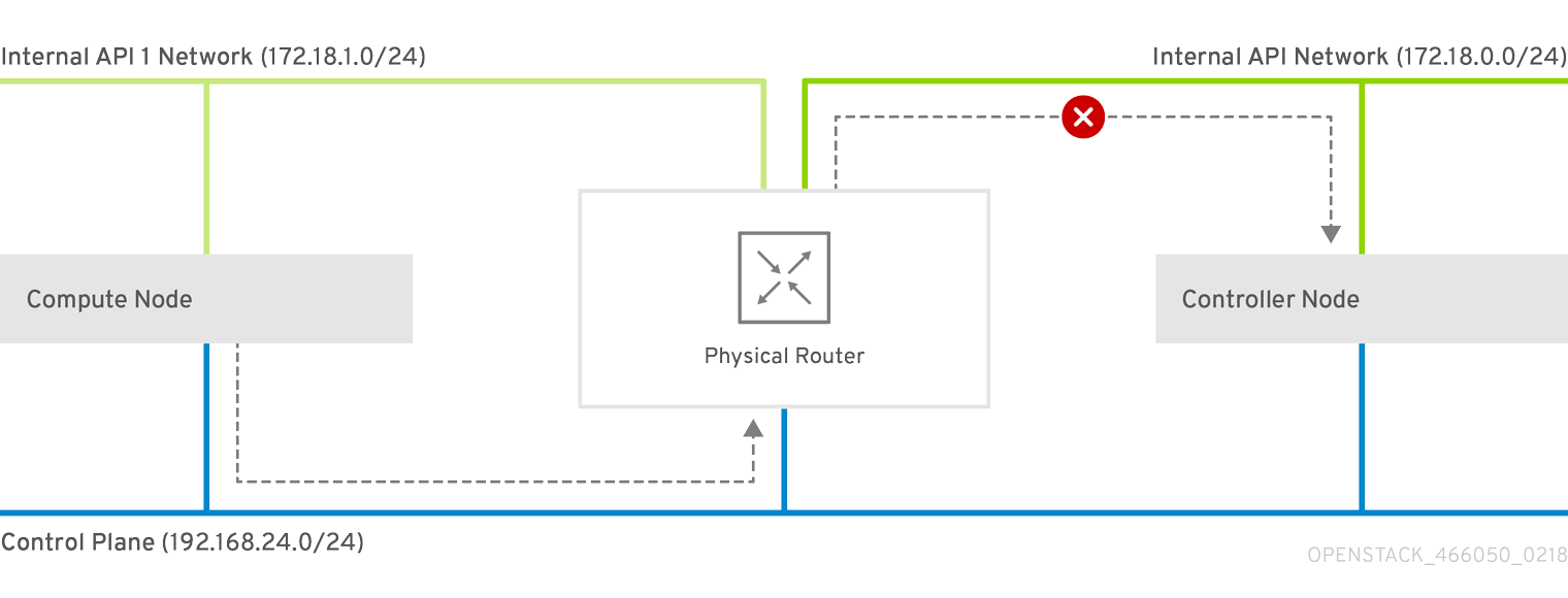
You need to configure these routes on the isolated networks because Red Hat Enterprise Linux by default implements strict reverse path filtering on inbound traffic. If an API is listening on the Internal API interface and a request comes in to that API, it only accepts the request if the return path route is on the Internal API interface. If the server is listening on the Internal API network but the return path to the client is through the Control Plane, then the server drops the requests due to the reverse path filter.
This following diagram shows an attempt to route traffic through the control plane, which will not succeed. The return route from the router to the controller node does not match the interface where the VIP is listening, so the packet is dropped. 192.168.24.0/24 is directly connected to the controller, so it is considered local to the Control Plane network.
Figure 4.1. Routed traffic through Control Plane
For comparison, this diagram shows routing running through the Internal API networks:
Figure 4.2. Routed traffic through Internal API

4.10. Assigning routes for composable networks
This procedure defines the routing for the leaf networks.
Procedure
-
Edit your
network-environment.yamlfile. Add the supernet route parameters to the
parameter_defaultssection. Each isolated network should have a supernet route applied. For example:parameter_defaults: StorageSupernet: 172.16.0.0/16 StorageMgmtSupernet: 172.17.0.0/16 InternalApiSupernet: 172.18.0.0/16 TenantSupernet: 172.19.0.0/16NoteThe network interface templates should contain the supernet parameters for each network. For example:
- type: vlan vlan_id: get_param: Storage0NetworkVlanID addresses: - ip_netmask: get_param: Storage0IpSubnet routes: - ip_netmask: get_param: StorageSupernet next_hop: get_param: Storage0InterfaceDefaultRouteAdd
ServiceNetMap HostnameResolveNetworkparameters to theparameter_defaultssection to provide each node in a leaf with a list of hostnames to use to resolve other leaf nodes. For example:parameter_defaults: ... ServiceNetMap: Compute1HostnameResolveNetwork: internal_api1 Compute2HostnameResolveNetwork: internal_api2 Compute3HostnameResolveNetwork: internal_api3 CephStorage1HostnameResolveNetwork: storage1 CephStorage2HostnameResolveNetwork: storage2 CephStorage3HostnameResolveNetwork: storage3The Compute nodes use the leaf’s Internal API network and the Ceph Storage nodes use the leaf’s Storage network.
Add the following
ExtraConfigsettings to theparameter_defaultssection to address routing for specific components on Compute and Ceph Storage nodes:Expand Table 4.1. Compute ExtraConfig parameters Parameter Set to this value nova::compute::libvirt::vncserver_listenIP address that the VNC servers listen to.
nova::compute::vncserver_proxyclient_addressIP address of the server running the VNC proxy client.
neutron::agents::ml2::ovs::local_ipIP address for OpenStack Networking (neutron) tunnel endpoints.
cold_migration_ssh_inbound_addrLocal IP address for cold migration SSH connections.
live_migration_ssh_inbound_addrLocal IP address for live migration SSH connections.
nova::migration::libvirt::live_migration_inbound_addrIP address used for live migration traffic.
NoteIf using SSL/TLS, prepend the network name with "fqdn_" to ensure the certificate is checked against the FQDN.
nova::my_ipIP address of the Compute (nova) service on the host.
tripleo::profile::base::database::mysql::client::mysql_client_bind_addressIP address of the database client. In this case, it is the
mysqlclient on the Compute nodes.Expand Table 4.2. CephAnsibleExtraConfig parameters Parameter Set to this value public_networkComma-separated list of all the storage networks that contain Ceph nodes (one per leaf), for example, 172.16.0.0/24,172.16.1.0/24,172.16.2.0/24
cluster_networkComma-separated list of the storage management networks that contain Ceph nodes (one per leaf), for example, 172.17.0.0/24,172.17.1.0/24,172.17.2.0/24
For example:
parameter_defaults: ... Compute1ExtraConfig: nova::compute::libvirt::vncserver_listen: "%{hiera('internal_api1')}" nova::compute::vncserver_proxyclient_address: "%{hiera('internal_api1')}" neutron::agents::ml2::ovs::local_ip: "%{hiera('tenant1')}" cold_migration_ssh_inbound_addr: "%{hiera('internal_api1')}" live_migration_ssh_inbound_addr: "%{hiera('internal_api1')}" nova::migration::libvirt::live_migration_inbound_addr: "%{hiera('internal_api1')}" nova::my_ip: "%{hiera('internal_api1')}" tripleo::profile::base::database::mysql::client::mysql_client_bind_address: "%{hiera('internal_api1')}" Compute2ExtraConfig: nova::compute::libvirt::vncserver_listen: "%{hiera('internal_api2')}" nova::compute::vncserver_proxyclient_address: "%{hiera('internal_api2')}" neutron::agents::ml2::ovs::local_ip: "%{hiera('tenant2')}" cold_migration_ssh_inbound_addr: "%{hiera('internal_api2')}" live_migration_ssh_inbound_addr: "%{hiera('internal_api2')}" nova::migration::libvirt::live_migration_inbound_addr: "%{hiera('internal_api2')}" nova::my_ip: "%{hiera('internal_api2')}" tripleo::profile::base::database::mysql::client::mysql_client_bind_address: "%{hiera('internal_api2')}" Compute3ExtraConfig: nova::compute::libvirt::vncserver_listen: "%{hiera('internal_api3')}" nova::compute::vncserver_proxyclient_address: "%{hiera('internal_api3')}" neutron::agents::ml2::ovs::local_ip: "%{hiera('tenant3')}" cold_migration_ssh_inbound_addr: "%{hiera('internal_api3')}" live_migration_ssh_inbound_addr: "%{hiera('internal_api3')}" nova::migration::libvirt::live_migration_inbound_addr: "%{hiera('internal_api3')}" nova::my_ip: "%{hiera('internal_api3')}" tripleo::profile::base::database::mysql::client::mysql_client_bind_address: "%{hiera('internal_api3')}" CephAnsibleExtraConfig: public_network: '172.16.0.0/24,172.16.1.0/24,172.16.2.0/24' cluster_network: '172.17.0.0/24,172.17.1.0/24,172.17.2.0/24'
4.11. Setting control plane parameters
You usually define networking details for isolated spine-leaf networks using a network_data file. The exception is the control plane network, which the undercloud created. However, the overcloud requires access to the control plane for each leaf. This requires some additional parameters, which you define in your network-environment.yaml file. For example, the following snippet is from an example NIC template for the Controller role on Leaf0
- type: interface
name: nic1
use_dhcp: false
dns_servers:
get_param: DnsServers
addresses:
- ip_netmask:
list_join:
- /
- - get_param: ControlPlaneIp
- get_param: ControlPlane0SubnetCidr
routes:
- ip_netmask: 169.254.169.254/32
next_hop:
get_param: Leaf0EC2MetadataIp
- ip_netmask: 192.168.10.0/24
next_hop:
get_param: ControlPlane0DefaultRouteIn this instance, we need to define the IP, subnet, metadata IP, and default route for the respective Control Plane network on Leaf 0.
Procedure
-
Edit your
network-environment.yamlfile. In the
parameter_defaultssection:Add the mapping to the main control plane subnet:
parameter_defaults: ... ControlPlaneSubnet: leaf0Add the control plane subnet mapping for each spine-leaf network:
parameter_defaults: ... Controller0ControlPlaneSubnet: leaf0 Compute0ControlPlaneSubnet: leaf0 Compute1ControlPlaneSubnet: leaf1 Compute2ControlPlaneSubnet: leaf2 CephStorage0ControlPlaneSubnet: leaf0 CephStorage1ControlPlaneSubnet: leaf1 CephStorage2ControlPlaneSubnet: leaf2Add the control plane routes for each leaf:
parameter_defaults: ... ControlPlane0DefaultRoute: 192.168.10.1 ControlPlane0SubnetCidr: '24' ControlPlane1DefaultRoute: 192.168.11.1 ControlPlane1SubnetCidr: '24' ControlPlane2DefaultRoute: 192.168.12.1 ControlPlane2SubnetCidr: '24'The default route parameters are typically the IP address set for the
gatewayof each provisioning subnet. Refer to yourundercloud.conffile for this information.Add the parameters for the EC2 metadata IPs:
parameter_defaults: ... Leaf0EC2MetadataIp: 192.168.10.1 Leaf1EC2MetadataIp: 192.168.11.1 Leaf2EC2MetadataIp: 192.168.12.1These act as routes through the control plane for the EC2 metadata service (169.254.169.254/32) and you should typically set these to the respective
gatewayfor each leaf on the provisioning network.
-
Save the
network-environment.yamlfile.
4.12. Deploying a spine-leaf enabled overcloud
All our files are now ready for our deployment. This section provides a review of each file and the deployment command:
Procedure
Review the
/home/stack/template/network_data_spine_leaf.yamlfile and ensure it contains each network for each leaf.NoteThere is currently no validation performed for the network subnet and
allocation_poolsvalues. Be certain you have defined these consistently and there is no conflict with existing networks.-
Review the NIC templates contained in
~/templates/spine-leaf-nics/and ensure the interfaces for each role on each leaf are correctly defined. -
Review the
network-environment.yamlenvironment file and ensure it contains all custom parameters that fall outside control of the network data file. This includes routes, control plane parameters, and aresource_registrysection that references the custom NIC templates for each role. -
Review the
/home/stack/templates/roles_data_spine_leaf.yamlvalues and ensure you have defined a role for each leaf. - Check the `/home/stack/templates/nodes_data.yaml file and ensure all roles have an assigned flavor and a node count. Check also that all nodes for each leaf are correctly tagged.
Run the
openstack overcloud deploycommand to apply the spine leaf configuration. For example:openstack overcloud deploy --templates \ -n /home/stack/template/network_data_spine_leaf.yaml \ -r /home/stack/templates/roles_data_spine_leaf.yaml \ -e /usr/share/openstack-tripleo-heat-templates/environments/network-isolation.yaml \ -e /home/stack/templates/network-environment.yaml \ -e /home/stack/templates/nodes_data.yaml \ -e [OTHER ENVIRONMENT FILES]-
The
network-isolation.yamlis the rendered name of the Jinja2 file in the same location (network-isolation.j2.yaml). Include this file to ensure the director isolates each networks to its correct leaf. This ensures the networks are created dynamically during the overcloud creation process. -
Include the
network-environment.yamlfile after thenetwork-isolation.yamland other network-based environment files. This ensures any parameters and resources defined withinnetwork-environment.yamloverride the same parameters and resources previously defined in other environment files. - Add any additional environment files. For example, an environment file with your container image locations or Ceph cluster configuration.
-
The
- Wait until the spine-leaf enabled overcloud deploys.
Appendix A. Example network_data file
# Storage
- name: Storage
vip: true
name_lower: storage
ip_subnet: '172.16.0.0/24'
allocation_pools: [{'start': '172.16.0.4', 'end': '172.16.0.250'}]
- name: Storage1
vip: false
name_lower: storage1
ip_subnet: '172.16.1.0/24'
allocation_pools: [{'start': '172.16.1.4', 'end': '172.16.1.250'}]
- name: Storage2
vip: false
name_lower: storage2
ip_subnet: '172.16.2.0/24'
allocation_pools: [{'start': '172.16.2.4', 'end': '172.16.2.250'}]
# StorageMgmt
- name: StorageMgmt
name_lower: storage_mgmt
vip: true
ip_subnet: '172.17.0.0/24'
allocation_pools: [{'start': '172.17.0.0', 'end': '172.17.0.250'}]
- name: StorageMgmt1
name_lower: storage_mgmt1
vip: false
ip_subnet: '172.17.1.0/24'
allocation_pools: [{'start': '172.17.1.4', 'end': '172.17.1.250'}]
- name: StorageMgmt2
name_lower: storage_mgmt2
vip: false
ip_subnet: '172.17.2.0/24'
allocation_pools: [{'start': '172.17.2.4', 'end': '172.17.2.250'}]
# Internal API
- name: InternalApi
  name_lower: internal_api
  vip: true
  ip_subnet: '172.18.0.0/24'
  allocation_pools: [{'start': '172.18.0.4', 'end': '172.18.0.250'}]
- name: InternalApi1
  name_lower: internal_api1
  vip: false
  ip_subnet: '172.18.1.0/24'
  allocation_pools: [{'start': '172.18.1.4', 'end': '172.18.1.250'}]
- name: InternalApi2
  name_lower: internal_api2
  vip: false
  ip_subnet: '172.18.2.0/24'
  allocation_pools: [{'start': '172.18.2.4', 'end': '172.18.2.250'}]
# Tenant
- name: Tenant
vip: false # Tenant network does not use VIPs
name_lower: tenant
ip_subnet: '172.19.0.0/24'
allocation_pools: [{'start': '172.19.0.4', 'end': '172.19.0.250'}]
- name: Tenant1
vip: false # Tenant network does not use VIPs
name_lower: tenant1
ip_subnet: '172.19.1.0/24'
allocation_pools: [{'start': '172.19.1.4', 'end': '172.19.1.250'}]
- name: Tenant2
vip: false # Tenant network does not use VIPs
name_lower: tenant2
ip_subnet: '172.19.2.0/24'
allocation_pools: [{'start': '172.19.2.4', 'end': '172.19.2.250'}]
- name: External
vip: true
name_lower: external
ip_subnet: '10.0.0.0/24'
allocation_pools: [{'start': '10.0.0.4', 'end': '10.0.0.250'}]
gateway_ip: '10.0.0.1'Appendix B. Custom NIC template
The following is a template to get you started with the configuring the network interface templates for spine leaf networking. Note that the resources section is incomplete and requires your interface definitions.
heat_template_version: queens
parameters:
# Supernets
StorageSupernet:
type: string
StorageMgmtSupernet:
type: string
InternalApiSupernet:
type: string
TenantSupernet:
type: string
ExternalSupernet:
type: string
# Default Routes
ControlPlane0DefaultRoute:
type: string
ControlPlane1DefaultRoute:
type: string
ControlPlane2DefaultRoute:
type: string
StorageInterfaceDefaultRoute:
type: string
Storage1InterfaceDefaultRoute:
type: string
Storage2InterfaceDefaultRoute:
type: string
StorageMgmtInterfaceDefaultRoute:
type: string
StorageMgmt1InterfaceDefaultRoute:
type: string
StorageMgmt2InterfaceDefaultRoute:
type: string
InternalApiInterfaceDefaultRoute:
type: string
InternalApi1InterfaceDefaultRoute:
type: string
InternalApi2InterfaceDefaultRoute:
type: string
TenantInterfaceDefaultRoute:
type: string
Tenant1InterfaceDefaultRoute:
type: string
Tenant2InterfaceDefaultRoute:
type: string
ExternalInterfaceDefaultRoute:
type: string
# IP subnets
StorageIpSubnet:
default: ''
type: string
Storage1IpSubnet:
default: ''
type: string
Storage2IpSubnet:
default: ''
type: string
StorageMgmtIpSubnet:
default: ''
type: string
StorageMgmt1IpSubnet:
default: ''
type: string
StorageMgmt2IpSubnet:
default: ''
type: string
InternalApiIpSubnet:
default: ''
type: string
InternalApi1IpSubnet:
default: ''
type: string
InternalApi2IpSubnet:
default: ''
type: string
TenantIpSubnet:
default: ''
type: string
Tenant1IpSubnet:
default: ''
type: string
Tenant2IpSubnet:
default: ''
type: string
ExternalIpSubnet:
default: ''
type: string
ManagementIpSubnet:
default: ''
type: string
# VLAN IDs
StorageNetworkVlanID:
type: number
Storage1NetworkVlanID:
type: number
Storage2NetworkVlanID:
type: number
StorageMgmtNetworkVlanID:
type: number
StorageMgmt1NetworkVlanID:
type: number
StorageMgmt2NetworkVlanID:
type: number
InternalApiNetworkVlanID:
type: number
InternalApi1NetworkVlanID:
type: number
InternalApi1NetworkVlanID:
type: number
TenantNetworkVlanID:
type: number
Tenant1NetworkVlanID:
type: number
Tenant2NetworkVlanID:
type: number
ExternalNetworkVlanID:
type: number
ManagementNetworkVlanID:
type: number
# Subnet CIDR
ControlPlane0SubnetCidr:
type: string
ControlPlane1SubnetCidr:
type: string
ControlPlane1SubnetCidr:
type: string
ControlPlaneIp:
type: string
DnsServers:
type: comma_delimited_list
# EC2 metadata server IPs
Leaf0EC2MetadataIp:
type: string
Leaf1EC2MetadataIp:
type: string
Leaf2EC2MetadataIp:
type: string
resources:
  OsNetConfigImpl:
    type: OS::Heat::SoftwareConfig
    properties:
      group: script
      config:
        str_replace:
          template:
            get_file: /usr/share/openstack-tripleo-heat-templates/network/scripts/run-os-net-config.sh
          params:
            $network_config:
              network_config:
[NETWORK CONFIG HERE]
outputs:
OS::stack_id:
description: The OsNetConfigImpl resource.
value:
get_resource: OsNetConfigImplAppendix C. Example roles_data file
###############################################################################
# Role: Controller0                                                           #
###############################################################################
- name: Controller0
  description: |
    Controller role that has all the controler services loaded and handles
    Database, Messaging and Network functions.
  CountDefault: 1
  tags:
    - primary
    - controller
  networks:
    - External
    - InternalApi
    - Storage
    - StorageMgmt
    - Tenant
  default_route_networks: ['External']
  HostnameFormatDefault: '%stackname%-controller0-%index%'
  uses_deprecated_params: True
  deprecated_param_extraconfig: 'controllerExtraConfig'
  deprecated_param_flavor: 'OvercloudControlFlavor'
  deprecated_param_image: 'controllerImage'
  deprecated_nic_config_name: 'controller.yaml'
  ServicesDefault:
    - OS::TripleO::Services::Aide
    - OS::TripleO::Services::AodhApi
    - OS::TripleO::Services::AodhEvaluator
    - OS::TripleO::Services::AodhListener
    - OS::TripleO::Services::AodhNotifier
    - OS::TripleO::Services::AuditD
    - OS::TripleO::Services::BarbicanApi
    - OS::TripleO::Services::BarbicanBackendSimpleCrypto
    - OS::TripleO::Services::BarbicanBackendDogtag
    - OS::TripleO::Services::BarbicanBackendKmip
    - OS::TripleO::Services::BarbicanBackendPkcs11Crypto
    - OS::TripleO::Services::CACerts
    - OS::TripleO::Services::CeilometerApi
    - OS::TripleO::Services::CeilometerCollector
    - OS::TripleO::Services::CeilometerExpirer
    - OS::TripleO::Services::CeilometerAgentCentral
    - OS::TripleO::Services::CeilometerAgentNotification
    - OS::TripleO::Services::CephExternal
    - OS::TripleO::Services::CephMds
    - OS::TripleO::Services::CephMgr
    - OS::TripleO::Services::CephMon
    - OS::TripleO::Services::CephRbdMirror
    - OS::TripleO::Services::CephRgw
    - OS::TripleO::Services::CertmongerUser
    - OS::TripleO::Services::CinderApi
    - OS::TripleO::Services::CinderBackendDellPs
    - OS::TripleO::Services::CinderBackendDellSc
    - OS::TripleO::Services::CinderBackendDellEMCUnity
    - OS::TripleO::Services::CinderBackendDellEMCVMAXISCSI
    - OS::TripleO::Services::CinderBackendDellEMCVNX
    - OS::TripleO::Services::CinderBackendDellEMCXTREMIOISCSI
    - OS::TripleO::Services::CinderBackendNetApp
    - OS::TripleO::Services::CinderBackendScaleIO
    - OS::TripleO::Services::CinderBackendVRTSHyperScale
    - OS::TripleO::Services::CinderBackup
    - OS::TripleO::Services::CinderHPELeftHandISCSI
    - OS::TripleO::Services::CinderScheduler
    - OS::TripleO::Services::CinderVolume
    - OS::TripleO::Services::Clustercheck
    - OS::TripleO::Services::Collectd
    - OS::TripleO::Services::Congress
    - OS::TripleO::Services::Docker
    - OS::TripleO::Services::Ec2Api
    - OS::TripleO::Services::Etcd
    - OS::TripleO::Services::ExternalSwiftProxy
    - OS::TripleO::Services::Fluentd
    - OS::TripleO::Services::GlanceApi
    - OS::TripleO::Services::GlanceRegistry
    - OS::TripleO::Services::GnocchiApi
    - OS::TripleO::Services::GnocchiMetricd
    - OS::TripleO::Services::GnocchiStatsd
    - OS::TripleO::Services::HAproxy
    - OS::TripleO::Services::HeatApi
    - OS::TripleO::Services::HeatApiCloudwatch
    - OS::TripleO::Services::HeatApiCfn
    - OS::TripleO::Services::HeatEngine
    - OS::TripleO::Services::Horizon
    - OS::TripleO::Services::Ipsec
    - OS::TripleO::Services::IronicApi
    - OS::TripleO::Services::IronicConductor
    - OS::TripleO::Services::IronicPxe
    - OS::TripleO::Services::Iscsid
    - OS::TripleO::Services::Keepalived
    - OS::TripleO::Services::Kernel
    - OS::TripleO::Services::Keystone
    - OS::TripleO::Services::LoginDefs
    - OS::TripleO::Services::ManilaApi
    - OS::TripleO::Services::ManilaBackendCephFs
    - OS::TripleO::Services::ManilaBackendIsilon
    - OS::TripleO::Services::ManilaBackendNetapp
    - OS::TripleO::Services::ManilaBackendUnity
    - OS::TripleO::Services::ManilaBackendVNX
    - OS::TripleO::Services::ManilaBackendVMAX
    - OS::TripleO::Services::ManilaScheduler
    - OS::TripleO::Services::ManilaShare
    - OS::TripleO::Services::Memcached
    - OS::TripleO::Services::MistralApi
    - OS::TripleO::Services::MistralEngine
    - OS::TripleO::Services::MistralExecutor
    - OS::TripleO::Services::MistralEventEngine
    - OS::TripleO::Services::MongoDb
    - OS::TripleO::Services::MySQL
    - OS::TripleO::Services::MySQLClient
    - OS::TripleO::Services::NeutronApi
    - OS::TripleO::Services::NeutronBgpVpnApi
    - OS::TripleO::Services::NeutronSfcApi
    - OS::TripleO::Services::NeutronCorePlugin
    - OS::TripleO::Services::NeutronDhcpAgent
    - OS::TripleO::Services::NeutronL2gwAgent
    - OS::TripleO::Services::NeutronL2gwApi
    - OS::TripleO::Services::NeutronL3Agent
    - OS::TripleO::Services::NeutronLbaasv2Agent
    - OS::TripleO::Services::NeutronLbaasv2Api
    - OS::TripleO::Services::NeutronLinuxbridgeAgent
    - OS::TripleO::Services::NeutronMetadataAgent
    - OS::TripleO::Services::NeutronML2FujitsuCfab
    - OS::TripleO::Services::NeutronML2FujitsuFossw
    - OS::TripleO::Services::NeutronOvsAgent
    - OS::TripleO::Services::NeutronVppAgent
    - OS::TripleO::Services::NovaApi
    - OS::TripleO::Services::NovaConductor
    - OS::TripleO::Services::NovaConsoleauth
    - OS::TripleO::Services::NovaIronic
    - OS::TripleO::Services::NovaMetadata
    - OS::TripleO::Services::NovaPlacement
    - OS::TripleO::Services::NovaScheduler
    - OS::TripleO::Services::NovaVncProxy
    - OS::TripleO::Services::Ntp
    - OS::TripleO::Services::ContainersLogrotateCrond
    - OS::TripleO::Services::OctaviaApi
    - OS::TripleO::Services::OctaviaDeploymentConfig
    - OS::TripleO::Services::OctaviaHealthManager
    - OS::TripleO::Services::OctaviaHousekeeping
    - OS::TripleO::Services::OctaviaWorker
    - OS::TripleO::Services::OpenDaylightApi
    - OS::TripleO::Services::OpenDaylightOvs
    - OS::TripleO::Services::OVNDBs
    - OS::TripleO::Services::OVNController
    - OS::TripleO::Services::Pacemaker
    - OS::TripleO::Services::PankoApi
    - OS::TripleO::Services::RabbitMQ
    - OS::TripleO::Services::Redis
    - OS::TripleO::Services::Rhsm
    - OS::TripleO::Services::RsyslogSidecar
    - OS::TripleO::Services::SaharaApi
    - OS::TripleO::Services::SaharaEngine
    - OS::TripleO::Services::Securetty
    - OS::TripleO::Services::SensuClient
    - OS::TripleO::Services::SkydiveAgent
    - OS::TripleO::Services::SkydiveAnalyzer
    - OS::TripleO::Services::Snmp
    - OS::TripleO::Services::Sshd
    - OS::TripleO::Services::SwiftProxy
    - OS::TripleO::Services::SwiftDispersion
    - OS::TripleO::Services::SwiftRingBuilder
    - OS::TripleO::Services::SwiftStorage
    - OS::TripleO::Services::Tacker
    - OS::TripleO::Services::Timezone
    - OS::TripleO::Services::TripleoFirewall
    - OS::TripleO::Services::TripleoPackages
    - OS::TripleO::Services::Tuned
    - OS::TripleO::Services::Vpp
    - OS::TripleO::Services::Zaqar
    - OS::TripleO::Services::Ptp
###############################################################################
# Role: Compute0                                                              #
###############################################################################
- name: Compute0
  description: |
    Basic Compute Node role
  CountDefault: 1
  networks:
    - InternalApi
    - Tenant
    - Storage
  HostnameFormatDefault: '%stackname%-compute0-%index%'
  uses_deprecated_params: True
  deprecated_param_image: 'NovaImage'
  deprecated_param_extraconfig: 'NovaComputeExtraConfig'
  deprecated_param_metadata: 'NovaComputeServerMetadata'
  deprecated_param_scheduler_hints: 'NovaComputeSchedulerHints'
  deprecated_param_ips: 'NovaComputeIPs'
  deprecated_server_resource_name: 'NovaCompute'
  deprecated_nic_config_name: 'compute.yaml'
  disable_upgrade_deployment: True
  ServicesDefault:
    - OS::TripleO::Services::Aide
    - OS::TripleO::Services::AuditD
    - OS::TripleO::Services::CACerts
    - OS::TripleO::Services::CephClient
    - OS::TripleO::Services::CephExternal
    - OS::TripleO::Services::CertmongerUser
    - OS::TripleO::Services::Collectd
    - OS::TripleO::Services::ComputeCeilometerAgent
    - OS::TripleO::Services::ComputeNeutronCorePlugin
    - OS::TripleO::Services::ComputeNeutronL3Agent
    - OS::TripleO::Services::ComputeNeutronMetadataAgent
    - OS::TripleO::Services::ComputeNeutronOvsAgent
    - OS::TripleO::Services::Docker
    - OS::TripleO::Services::Fluentd
    - OS::TripleO::Services::Ipsec
    - OS::TripleO::Services::Iscsid
    - OS::TripleO::Services::Kernel
    - OS::TripleO::Services::LoginDefs
    - OS::TripleO::Services::MySQLClient
    - OS::TripleO::Services::NeutronBgpVpnBagpipe
    - OS::TripleO::Services::NeutronLinuxbridgeAgent
    - OS::TripleO::Services::NeutronVppAgent
    - OS::TripleO::Services::NovaCompute
    - OS::TripleO::Services::NovaLibvirt
    - OS::TripleO::Services::NovaMigrationTarget
    - OS::TripleO::Services::Ntp
    - OS::TripleO::Services::ContainersLogrotateCrond
    - OS::TripleO::Services::OpenDaylightOvs
    - OS::TripleO::Services::Rhsm
    - OS::TripleO::Services::RsyslogSidecar
    - OS::TripleO::Services::Securetty
    - OS::TripleO::Services::SensuClient
    - OS::TripleO::Services::SkydiveAgent
    - OS::TripleO::Services::Snmp
    - OS::TripleO::Services::Sshd
    - OS::TripleO::Services::Timezone
    - OS::TripleO::Services::TripleoFirewall
    - OS::TripleO::Services::TripleoPackages
    - OS::TripleO::Services::Tuned
    - OS::TripleO::Services::Vpp
    - OS::TripleO::Services::OVNController
    - OS::TripleO::Services::OVNMetadataAgent
    - OS::TripleO::Services::Ptp
###############################################################################
# Role: Compute1                                                              #
###############################################################################
- name: Compute1
  description: |
    Basic Compute Node role
  CountDefault: 1
  networks:
    - InternalApi1
    - Tenant1
    - Storage1
  HostnameFormatDefault: '%stackname%-compute1-%index%'
  uses_deprecated_params: True
  deprecated_param_image: 'NovaImage'
  deprecated_param_extraconfig: 'NovaComputeExtraConfig'
  deprecated_param_metadata: 'NovaComputeServerMetadata'
  deprecated_param_scheduler_hints: 'NovaComputeSchedulerHints'
  deprecated_param_ips: 'NovaComputeIPs'
  deprecated_server_resource_name: 'NovaCompute'
  deprecated_nic_config_name: 'compute.yaml'
  disable_upgrade_deployment: True
  ServicesDefault:
    - OS::TripleO::Services::Aide
    - OS::TripleO::Services::AuditD
    - OS::TripleO::Services::CACerts
    - OS::TripleO::Services::CephClient
    - OS::TripleO::Services::CephExternal
    - OS::TripleO::Services::CertmongerUser
    - OS::TripleO::Services::Collectd
    - OS::TripleO::Services::ComputeCeilometerAgent
    - OS::TripleO::Services::ComputeNeutronCorePlugin
    - OS::TripleO::Services::ComputeNeutronL3Agent
    - OS::TripleO::Services::ComputeNeutronMetadataAgent
    - OS::TripleO::Services::ComputeNeutronOvsAgent
    - OS::TripleO::Services::Docker
    - OS::TripleO::Services::Fluentd
    - OS::TripleO::Services::Ipsec
    - OS::TripleO::Services::Iscsid
    - OS::TripleO::Services::Kernel
    - OS::TripleO::Services::LoginDefs
    - OS::TripleO::Services::MySQLClient
    - OS::TripleO::Services::NeutronBgpVpnBagpipe
    - OS::TripleO::Services::NeutronLinuxbridgeAgent
    - OS::TripleO::Services::NeutronVppAgent
    - OS::TripleO::Services::NovaCompute
    - OS::TripleO::Services::NovaLibvirt
    - OS::TripleO::Services::NovaMigrationTarget
    - OS::TripleO::Services::Ntp
    - OS::TripleO::Services::ContainersLogrotateCrond
    - OS::TripleO::Services::OpenDaylightOvs
    - OS::TripleO::Services::Rhsm
    - OS::TripleO::Services::RsyslogSidecar
    - OS::TripleO::Services::Securetty
    - OS::TripleO::Services::SensuClient
    - OS::TripleO::Services::SkydiveAgent
    - OS::TripleO::Services::Snmp
    - OS::TripleO::Services::Sshd
    - OS::TripleO::Services::Timezone
    - OS::TripleO::Services::TripleoFirewall
    - OS::TripleO::Services::TripleoPackages
    - OS::TripleO::Services::Tuned
    - OS::TripleO::Services::Vpp
    - OS::TripleO::Services::OVNController
    - OS::TripleO::Services::OVNMetadataAgent
    - OS::TripleO::Services::Ptp
###############################################################################
# Role: Compute2                                                              #
###############################################################################
- name: Compute2
  description: |
    Basic Compute Node role
  CountDefault: 1
  networks:
    - InternalApi2
    - Tenant2
    - Storage2
  HostnameFormatDefault: '%stackname%-compute2-%index%'
  uses_deprecated_params: True
  deprecated_param_image: 'NovaImage'
  deprecated_param_extraconfig: 'NovaComputeExtraConfig'
  deprecated_param_metadata: 'NovaComputeServerMetadata'
  deprecated_param_scheduler_hints: 'NovaComputeSchedulerHints'
  deprecated_param_ips: 'NovaComputeIPs'
  deprecated_server_resource_name: 'NovaCompute'
  deprecated_nic_config_name: 'compute.yaml'
  disable_upgrade_deployment: True
  ServicesDefault:
    - OS::TripleO::Services::Aide
    - OS::TripleO::Services::AuditD
    - OS::TripleO::Services::CACerts
    - OS::TripleO::Services::CephClient
    - OS::TripleO::Services::CephExternal
    - OS::TripleO::Services::CertmongerUser
    - OS::TripleO::Services::Collectd
    - OS::TripleO::Services::ComputeCeilometerAgent
    - OS::TripleO::Services::ComputeNeutronCorePlugin
    - OS::TripleO::Services::ComputeNeutronL3Agent
    - OS::TripleO::Services::ComputeNeutronMetadataAgent
    - OS::TripleO::Services::ComputeNeutronOvsAgent
    - OS::TripleO::Services::Docker
    - OS::TripleO::Services::Fluentd
    - OS::TripleO::Services::Ipsec
    - OS::TripleO::Services::Iscsid
    - OS::TripleO::Services::Kernel
    - OS::TripleO::Services::LoginDefs
    - OS::TripleO::Services::MySQLClient
    - OS::TripleO::Services::NeutronBgpVpnBagpipe
    - OS::TripleO::Services::NeutronLinuxbridgeAgent
    - OS::TripleO::Services::NeutronVppAgent
    - OS::TripleO::Services::NovaCompute
    - OS::TripleO::Services::NovaLibvirt
    - OS::TripleO::Services::NovaMigrationTarget
    - OS::TripleO::Services::Ntp
    - OS::TripleO::Services::ContainersLogrotateCrond
    - OS::TripleO::Services::OpenDaylightOvs
    - OS::TripleO::Services::Rhsm
    - OS::TripleO::Services::RsyslogSidecar
    - OS::TripleO::Services::Securetty
    - OS::TripleO::Services::SensuClient
    - OS::TripleO::Services::SkydiveAgent
    - OS::TripleO::Services::Snmp
    - OS::TripleO::Services::Sshd
    - OS::TripleO::Services::Timezone
    - OS::TripleO::Services::TripleoFirewall
    - OS::TripleO::Services::TripleoPackages
    - OS::TripleO::Services::Tuned
    - OS::TripleO::Services::Vpp
    - OS::TripleO::Services::OVNController
    - OS::TripleO::Services::OVNMetadataAgent
    - OS::TripleO::Services::Ptp
###############################################################################
# Role: CephStorage0                                                          #
###############################################################################
- name: CephStorage0
  description: |
    Ceph OSD Storage node role
  networks:
    - Storage0
    - StorageMgmt0
  HostnameFormatDefault: '%stackname%-cephstorage0-%index%'
  uses_deprecated_params: False
  deprecated_nic_config_name: 'ceph-storage.yaml'
  ServicesDefault:
    - OS::TripleO::Services::Aide
    - OS::TripleO::Services::AuditD
    - OS::TripleO::Services::CACerts
    - OS::TripleO::Services::CephOSD
    - OS::TripleO::Services::CertmongerUser
    - OS::TripleO::Services::Collectd
    - OS::TripleO::Services::Docker
    - OS::TripleO::Services::Fluentd
    - OS::TripleO::Services::Ipsec
    - OS::TripleO::Services::Kernel
    - OS::TripleO::Services::LoginDefs
    - OS::TripleO::Services::MySQLClient
    - OS::TripleO::Services::Ntp
    - OS::TripleO::Services::ContainersLogrotateCrond
    - OS::TripleO::Services::Rhsm
    - OS::TripleO::Services::RsyslogSidecar
    - OS::TripleO::Services::Securetty
    - OS::TripleO::Services::SensuClient
    - OS::TripleO::Services::Snmp
    - OS::TripleO::Services::Sshd
    - OS::TripleO::Services::Timezone
    - OS::TripleO::Services::TripleoFirewall
    - OS::TripleO::Services::TripleoPackages
    - OS::TripleO::Services::Tuned
    - OS::TripleO::Services::Ptp
###############################################################################
# Role: CephStorage1                                                          #
###############################################################################
- name: CephStorage1
  description: |
    Ceph OSD Storage node role
  networks:
    - Storage1
    - StorageMgmt1
  HostnameFormatDefault: '%stackname%-cephstorage1-%index%'
  uses_deprecated_params: False
  deprecated_nic_config_name: 'ceph-storage.yaml'
  ServicesDefault:
    - OS::TripleO::Services::Aide
    - OS::TripleO::Services::AuditD
    - OS::TripleO::Services::CACerts
    - OS::TripleO::Services::CephOSD
    - OS::TripleO::Services::CertmongerUser
    - OS::TripleO::Services::Collectd
    - OS::TripleO::Services::Docker
    - OS::TripleO::Services::Fluentd
    - OS::TripleO::Services::Ipsec
    - OS::TripleO::Services::Kernel
    - OS::TripleO::Services::LoginDefs
    - OS::TripleO::Services::MySQLClient
    - OS::TripleO::Services::Ntp
    - OS::TripleO::Services::ContainersLogrotateCrond
    - OS::TripleO::Services::Rhsm
    - OS::TripleO::Services::RsyslogSidecar
    - OS::TripleO::Services::Securetty
    - OS::TripleO::Services::SensuClient
    - OS::TripleO::Services::Snmp
    - OS::TripleO::Services::Sshd
    - OS::TripleO::Services::Timezone
    - OS::TripleO::Services::TripleoFirewall
    - OS::TripleO::Services::TripleoPackages
    - OS::TripleO::Services::Tuned
    - OS::TripleO::Services::Ptp
###############################################################################
# Role: CephStorage2                                                          #
###############################################################################
- name: CephStorage2
  description: |
    Ceph OSD Storage node role
  networks:
    - Storage2
    - StorageMgmt2
  HostnameFormatDefault: '%stackname%-cephstorage2-%index%'
  uses_deprecated_params: False
  deprecated_nic_config_name: 'ceph-storage.yaml'
  ServicesDefault:
    - OS::TripleO::Services::Aide
    - OS::TripleO::Services::AuditD
    - OS::TripleO::Services::CACerts
    - OS::TripleO::Services::CephOSD
    - OS::TripleO::Services::CertmongerUser
    - OS::TripleO::Services::Collectd
    - OS::TripleO::Services::Docker
    - OS::TripleO::Services::Fluentd
    - OS::TripleO::Services::Ipsec
    - OS::TripleO::Services::Kernel
    - OS::TripleO::Services::LoginDefs
    - OS::TripleO::Services::MySQLClient
    - OS::TripleO::Services::Ntp
    - OS::TripleO::Services::ContainersLogrotateCrond
    - OS::TripleO::Services::Rhsm
    - OS::TripleO::Services::RsyslogSidecar
    - OS::TripleO::Services::Securetty
    - OS::TripleO::Services::SensuClient
    - OS::TripleO::Services::Snmp
    - OS::TripleO::Services::Sshd
    - OS::TripleO::Services::Timezone
    - OS::TripleO::Services::TripleoFirewall
    - OS::TripleO::Services::TripleoPackages
    - OS::TripleO::Services::Tuned
    - OS::TripleO::Services::Ptp
Appendix D. Example network_environment file
resource_registry:
  OS::TripleO::ControllerLeaf2::Net::SoftwareConfig: /home/stack/nics/controllerleaf2.yaml
  OS::TripleO::ComputeLeaf3::Net::SoftwareConfig: /home/stack/nics/computeleaf3.yaml
  OS::TripleO::ComputeLeaf4::Net::SoftwareConfig: /home/stack/nics/computeleaf4.yaml
parameter_defaults:
  ControlPlaneSubnet: leaf1
  ControllerLeaf2ControlPlaneSubnet: leaf2
  ComputeLeaf3ControlPlaneSubnet: leaf3
  ComputeLeaf4ControlPlaneSubnet: leaf4
  ControlPlaneDefaultRoute: 10.10.1.1
  ControlPlaneSubnetCidr: '24'
  ControlPlane2DefaultRoute: 10.10.2.1
  ControlPlane2SubnetCidr: '24'
  ControlPlane3DefaultRoute: 10.10.3.1
  ControlPlane3SubnetCidr: '24'
  ControlPlane4DefaultRoute: 10.10.4.1
  ControlPlane4SubnetCidr: '24'
  InternalApiSupernet: 10.20.0.0/16
  TenantSupernet: 10.30.0.0/16
  ProvisioningSupernet: 10.10.0.0/16
  EC2MetadataIp: 10.10.1.10
  Leaf2EC2MetadataIp: 10.10.1.10
  Leaf3EC2MetadataIp: 10.10.1.10
  Leaf4EC2MetadataIp: 10.10.1.10

  ServiceNetMap:
    ComputeLeaf3HostnameResolveNetwork: internal_api3
    ComputeLeaf4HostnameResolveNetwork: internal_api4

  ComputeLeaf3ExtraConfig:
    nova::compute::libvirt::vncserver_listen: "%{hiera('internal_api3')}"
    nova::compute::vncserver_proxyclient_address: "%{hiera('internal_api3')}"
    neutron::agents::ml2::ovs::local_ip: "%{hiera('tenant3')}"
    cold_migration_ssh_inbound_addr: "%{hiera('internal_api3')}"
    live_migration_ssh_inbound_addr: "%{hiera('internal_api3')}"
    nova::migration::libvirt::live_migration_inbound_addr: "%{hiera('internal_api3')}"
    nova::my_ip: "%{hiera('internal_api3')}"
    tripleo::profile::base::database::mysql::client::mysql_client_bind_address: "%{hiera('internal_api3')}"

  ComputeLeaf4ExtraConfig:
    nova::compute::libvirt::vncserver_listen: "%{hiera('internal_api4')}"
    nova::compute::vncserver_proxyclient_address: "%{hiera('internal_api4')}"
    neutron::agents::ml2::ovs::local_ip: "%{hiera('tenant4')}"
    cold_migration_ssh_inbound_addr: "%{hiera('internal_api4')}"
    live_migration_ssh_inbound_addr: "%{hiera('internal_api4')}"
    nova::migration::libvirt::live_migration_inbound_addr: "%{hiera('internal_api4')}"
    nova::my_ip: "%{hiera('internal_api4')}"
    tripleo::profile::base::database::mysql::client::mysql_client_bind_address: "%{hiera('internal_api4')}"