이 콘텐츠는 선택한 언어로 제공되지 않습니다.
High Availability Add-On Reference
Red Hat Enterprise Linux 7
Reference guide for configuration and management of the High Availability Add-On
Abstract
Red Hat High Availability Add-On Reference provides reference information about installing, configuring, and managing the Red Hat High Availability Add-On for Red Hat Enterprise Linux 7.
Chapter 1. Red Hat High Availability Add-On Configuration and Management Reference Overview
링크 복사링크가 클립보드에 복사되었습니다!
This document provides descriptions of the options and features that the Red Hat High Availability Add-On using Pacemaker supports. For a step by step basic configuration example, see Red Hat High Availability Add-On Administration.
You can configure a Red Hat High Availability Add-On cluster with the
pcs configuration interface or with the pcsd GUI interface.
1.1. New and Changed Features
링크 복사링크가 클립보드에 복사되었습니다!
This section lists features of the Red Hat High Availability Add-On that are new since the initial release of Red Hat Enterprise Linux 7.
1.1.1. New and Changed Features for Red Hat Enterprise Linux 7.1
링크 복사링크가 클립보드에 복사되었습니다!
Red Hat Enterprise Linux 7.1 includes the following documentation and feature updates and changes.
- The
pcs resource cleanupcommand can now reset the resource status andfailcountfor all resources, as documented in Section 6.11, “Cluster Resources Cleanup”. - You can specify a
lifetimeparameter for thepcs resource movecommand, as documented in Section 8.1, “Manually Moving Resources Around the Cluster”. - As of Red Hat Enterprise Linux 7.1, you can use the
pcs aclcommand to set permissions for local users to allow read-only or read-write access to the cluster configuration by using access control lists (ACLs). For information on ACLs, see Section 4.5, “Setting User Permissions”. - Section 7.2.3, “Ordered Resource Sets” and Section 7.3, “Colocation of Resources” have been extensively updated and clarified.
- Section 6.1, “Resource Creation” documents the
disabledparameter of thepcs resource createcommand, to indicate that the resource being created is not started automatically. - Section 10.1, “Configuring Quorum Options” documents the new
cluster quorum unblockfeature, which prevents the cluster from waiting for all nodes when establishing quorum. - Section 6.1, “Resource Creation” documents the
beforeandafterparameters of thepcs resource createcommand, which can be used to configure resource group ordering. - As of the Red Hat Enterprise Linux 7.1 release, you can backup the cluster configuration in a tarball and restore the cluster configuration files on all nodes from backup with the
backupandrestoreoptions of thepcs configcommand. For information on this feature, see Section 3.8, “Backing Up and Restoring a Cluster Configuration”. - Small clarifications have been made throughout this document.
1.1.2. New and Changed Features for Red Hat Enterprise Linux 7.2
링크 복사링크가 클립보드에 복사되었습니다!
Red Hat Enterprise Linux 7.2 includes the following documentation and feature updates and changes.
- You can now use the
pcs resource relocate runcommand to move a resource to its preferred node, as determined by current cluster status, constraints, location of resources and other settings. For information on this command, see Section 8.1.2, “Moving a Resource to its Preferred Node”. - Section 13.2, “Event Notification with Monitoring Resources” has been modified and expanded to better document how to configure the
ClusterMonresource to execute an external program to determine what to do with cluster notifications. - When configuring fencing for redundant power supplies, you now are only required to define each device once and to specify that both devices are required to fence the node. For information on configuring fencing for redundant power supplies, see Section 5.10, “Configuring Fencing for Redundant Power Supplies”.
- This document now provides a procedure for adding a node to an existing cluster in Section 4.4.3, “Adding Cluster Nodes”.
- The new
resource-discoverylocation constraint option allows you to indicate whether Pacemaker should perform resource discovery on a node for a specified resource, as documented in Table 7.1, “Simple Location Constraint Options”. - Small clarifications and corrections have been made throughout this document.
1.1.3. New and Changed Features for Red Hat Enterprise Linux 7.3
링크 복사링크가 클립보드에 복사되었습니다!
Red Hat Enterprise Linux 7.3 includes the following documentation and feature updates and changes.
- Section 9.4, “The pacemaker_remote Service”, has been wholly rewritten for this version of the document.
- You can configure Pacemaker alerts by means of alert agents, which are external programs that the cluster calls in the same manner as the cluster calls resource agents to handle resource configuration and operation. Pacemaker alert agents are described in Section 13.1, “Pacemaker Alert Agents (Red Hat Enterprise Linux 7.3 and later)”.
- New quorum administration commands are supported with this release which allow you to display the quorum status and to change the
expected_votesparameter. These commands are described in Section 10.2, “Quorum Administration Commands (Red Hat Enterprise Linux 7.3 and Later)”. - You can now modify general quorum options for your cluster with the
pcs quorum updatecommand, as described in Section 10.3, “Modifying Quorum Options (Red Hat Enterprise Linux 7.3 and later)”. - You can configure a separate quorum device which acts as a third-party arbitration device for the cluster. The primary use of this feature is to allow a cluster to sustain more node failures than standard quorum rules allow. This feature is provided for technical preview only. For information on quorum devices, see Section 10.5, “Quorum Devices”.
- Red Hat Enterprise Linux release 7.3 provides the ability to configure high availability clusters that span multiple sites through the use of a Booth cluster ticket manager. This feature is provided for technical preview only. For information on the Booth cluster ticket manager, see Chapter 14, Configuring Multi-Site Clusters with Pacemaker.
- When configuring a KVM guest node running a the
pacemaker_remoteservice, you can include guest nodes in groups, which allows you to group a storage device, file system, and VM. For information on configuring KVM guest nodes, see Section 9.4.5, “Configuration Overview: KVM Guest Node”.
Additionally, small clarifications and corrections have been made throughout this document.
1.1.4. New and Changed Features for Red Hat Enterprise Linux 7.4
링크 복사링크가 클립보드에 복사되었습니다!
Red Hat Enterprise Linux 7.4 includes the following documentation and feature updates and changes.
- Red Hat Enterprise Linux release 7.4 provides full support for the ability to configure high availability clusters that span multiple sites through the use of a Booth cluster ticket manager. For information on the Booth cluster ticket manager, see Chapter 14, Configuring Multi-Site Clusters with Pacemaker.
- Red Hat Enterprise Linux 7.4 provides full support for the ability to configure a separate quorum device which acts as a third-party arbitration device for the cluster. The primary use of this feature is to allow a cluster to sustain more node failures than standard quorum rules allow. For information on quorum devices, see Section 10.5, “Quorum Devices”.
- You can now specify nodes in fencing topology by a regular expression applied on a node name and by a node attribute and its value. For information on configuring fencing levels, see Section 5.9, “Configuring Fencing Levels”.
- Red Hat Enterprise Linux 7.4 supports the
NodeUtilizationresource agent, which can detect the system parameters of available CPU, host memory availability, and hypervisor memory availability and add these parameters into the CIB. For information on this resource agent, see Section 9.6.5, “The NodeUtilization Resource Agent (Red Hat Enterprise Linux 7.4 and later)”. - For Red Hat Enterprise Linux 7.4, the
cluster node add-guestand thecluster node remove-guestcommands replace thecluster remote-node addandcluster remote-node removecommands. Thepcs cluster node add-guestcommand sets up theauthkeyfor guest nodes and thepcs cluster node add-remotecommand sets up theauthkeyfor remote nodes. For updated guest and remote node configuration procedures, see Section 9.3, “Configuring a Virtual Domain as a Resource”. - Red Hat Enterprise Linux 7.4 supports the
systemdresource-agents-depstarget. This allows you to configure the appropriate startup order for a cluster that includes resources with dependencies that are not themselves managed by the cluster, as described in Section 9.7, “Configuring Startup Order for Resource Dependencies not Managed by Pacemaker (Red Hat Enterprise Linux 7.4 and later)”. - The format for the command to create a resource as a master/slave clone has changed for this release. For information on creating a master/slave clone, see Section 9.2, “Multistate Resources: Resources That Have Multiple Modes”.
1.1.5. New and Changed Features for Red Hat Enterprise Linux 7.5
링크 복사링크가 클립보드에 복사되었습니다!
Red Hat Enterprise Linux 7.5 includes the following documentation and feature updates and changes.
- As of Red Hat Enterprise Linux 7.5, you can use the
pcs_snmp_agentdaemon to query a Pacemaker cluster for data by means of SNMP. For information on querying a cluster with SNMP, see Section 9.8, “Querying a Pacemaker Cluster with SNMP (Red Hat Enterprise Linux 7.5 and later)”.
1.1.6. New and Changed Features for Red Hat Enterprise Linux 7.8
링크 복사링크가 클립보드에 복사되었습니다!
Red Hat Enterprise Linux 7.8 includes the following documentation and feature updates and changes.
- As of Red Hat Enterprise Linux 7.8, you can configure Pacemaker so that when a node shuts down cleanly, the resources attached to the node will be locked to the node and unable to start elsewhere until they start again when the node that has shut down rejoins the cluster. This allows you to power down nodes during maintenance windows when service outages are acceptable without causing that node’s resources to fail over to other nodes in the cluster. For information on configuring resources to remain stopped on clean node shutdown, see Section 9.9, “ Configuring Resources to Remain Stopped on Clean Node Shutdown (Red Hat Enterprise Linux 7.8 and later) ”.
1.2. Installing Pacemaker configuration tools
링크 복사링크가 클립보드에 복사되었습니다!
You can use the following
yum install command to install the Red Hat High Availability Add-On software packages along with all available fence agents from the High Availability channel.
# yum install pcs pacemaker fence-agents-all
Alternately, you can install the Red Hat High Availability Add-On software packages along with only the fence agent that you require with the following command.
# yum install pcs pacemaker fence-agents-model
The following command displays a listing of the available fence agents.
# rpm -q -a | grep fence
fence-agents-rhevm-4.0.2-3.el7.x86_64
fence-agents-ilo-mp-4.0.2-3.el7.x86_64
fence-agents-ipmilan-4.0.2-3.el7.x86_64
...
The
lvm2-cluster and gfs2-utils packages are part of ResilientStorage channel. You can install them, as needed, with the following command.
# yum install lvm2-cluster gfs2-utilsWarning
After you install the Red Hat High Availability Add-On packages, you should ensure that your software update preferences are set so that nothing is installed automatically. Installation on a running cluster can cause unexpected behaviors.
1.3. Configuring the iptables Firewall to Allow Cluster Components
링크 복사링크가 클립보드에 복사되었습니다!
Note
The ideal firewall configuration for cluster components depends on the local environment, where you may need to take into account such considerations as whether the nodes have multiple network interfaces or whether off-host firewalling is present. The example here, which opens the ports that are generally required by a Pacemaker cluster, should be modified to suit local conditions.
Table 1.1, “Ports to Enable for High Availability Add-On” shows the ports to enable for the Red Hat High Availability Add-On and provides an explanation for what the port is used for. You can enable all of these ports by means of the
firewalld daemon by executing the following commands.
# firewall-cmd --permanent --add-service=high-availability
# firewall-cmd --add-service=high-availability| Port | When Required |
|---|---|
|
TCP 2224
|
Required on all nodes (needed by the
pcsd Web UI and required for node-to-node communication)
It is crucial to open port 2224 in such a way that
pcs from any node can talk to all nodes in the cluster, including itself. When using the Booth cluster ticket manager or a quorum device you must open port 2224 on all related hosts, such as Booth arbiters or the quorum device host.
|
|
TCP 3121
|
Required on all nodes if the cluster has any Pacemaker Remote nodes
Pacemaker's
crmd daemon on the full cluster nodes will contact the pacemaker_remoted daemon on Pacemaker Remote nodes at port 3121. If a separate interface is used for cluster communication, the port only needs to be open on that interface. At a minimum, the port should open on Pacemaker Remote nodes to full cluster nodes. Because users may convert a host between a full node and a remote node, or run a remote node inside a container using the host's network, it can be useful to open the port to all nodes. It is not necessary to open the port to any hosts other than nodes.
|
|
TCP 5403
|
Required on the quorum device host when using a quorum device with
corosync-qnetd. The default value can be changed with the -p option of the corosync-qnetd command.
|
|
UDP 5404
|
Required on corosync nodes if
corosync is configured for multicast UDP
|
|
UDP 5405
|
Required on all corosync nodes (needed by
corosync)
|
|
TCP 21064
|
Required on all nodes if the cluster contains any resources requiring DLM (such as
clvm or GFS2)
|
|
TCP 9929, UDP 9929
|
Required to be open on all cluster nodes and booth arbitrator nodes to connections from any of those same nodes when the Booth ticket manager is used to establish a multi-site cluster.
|
1.4. The Cluster and Pacemaker Configuration Files
링크 복사링크가 클립보드에 복사되었습니다!
The configuration files for the Red Hat High Availability add-on are
corosync.conf and cib.xml.
The
corosync.conf file provides the cluster parameters used by corosync, the cluster manager that Pacemaker is built on. In general, you should not edit the corosync.conf directly but, instead, use the pcs or pcsd interface. However, there may be a situation where you do need to edit this file directly. For information on editing the corosync.conf file, see Editing the corosync.conf file in Red Hat Enterprise Linux 7.
The
cib.xml file is an XML file that represents both the cluster’s configuration and current state of all resources in the cluster. This file is used by Pacemaker's Cluster Information Base (CIB). The contents of the CIB are automatically kept in sync across the entire cluster Do not edit the cib.xml file directly; use the pcs or pcsd interface instead.
1.5. Cluster Configuration Considerations
링크 복사링크가 클립보드에 복사되었습니다!
When configuring a Red Hat High Availability Add-On cluster, you must take the following considerations into account:
- Red Hat does not support cluster deployments greater than 32 nodes for RHEL 7.7 (and later). It is possible, however, to scale beyond that limit with remote nodes running the
pacemaker_remoteservice. For information on thepacemaker_remoteservice, see Section 9.4, “The pacemaker_remote Service”. - The use of Dynamic Host Configuration Protocol (DHCP) for obtaining an IP address on a network interface that is utilized by the
corosyncdaemons is not supported. The DHCP client can periodically remove and re-add an IP address to its assigned interface during address renewal. This will result incorosyncdetecting a connection failure, which will result in fencing activity from any other nodes in the cluster usingcorosyncfor heartbeat connectivity.
1.6. Updating a Red Hat Enterprise Linux High Availability Cluster
링크 복사링크가 클립보드에 복사되었습니다!
Updating packages that make up the RHEL High Availability and Resilient Storage Add-Ons, either individually or as a whole, can be done in one of two general ways:
- Rolling Updates: Remove one node at a time from service, update its software, then integrate it back into the cluster. This allows the cluster to continue providing service and managing resources while each node is updated.
- Entire Cluster Update: Stop the entire cluster, apply updates to all nodes, then start the cluster back up.
Warning
It is critical that when performing software update procedures for Red Hat Enterprise LInux High Availability and Resilient Storage clusters, you ensure that any node that will undergo updates is not an active member of the cluster before those updates are initiated.
For a full description of each of these methods and the procedures to follow for the updates, see Recommended Practices for Applying Software Updates to a RHEL High Availability or Resilient Storage Cluster.
1.7. Issues with Live Migration of VMs in a RHEL cluster
링크 복사링크가 클립보드에 복사되었습니다!
Information on support policies for RHEL high availability clusters with virtualized cluster members can be found in Support Policies for RHEL High Availability Clusters - General Conditions with Virtualized Cluster Members. As noted, Red Hat does not support live migration of active cluster nodes across hypervisors or hosts. If you need to perform a live migration, you will first need to stop the cluster services on the VM to remove the node from the cluster, and then start the cluster back up after performing the migration.
The following steps outline the procedure for removing a VM from a cluster, migrating the VM, and restoring the VM to the cluster.
Note
Before performing this procedure, consider the effect on cluster quorum of removing a cluster node. For example, if you have a three node cluster and you remove one node, your cluster can withstand only one more node failure. If one node of a three node cluster is already down, removing a second node will lose quorum.
- If any preparations need to be made before stopping or moving the resources or software running on the VM to migrate, perform those steps.
- Move any managed resources off the VM. If there are specific requirements or preferences for where resources should be relocated, then consider creating new location constraints to place the resources on the correct node.
- Place the VM in standby mode to ensure it is not considered in service, and to cause any remaining resources to be relocated elsewhere or stopped.
# pcs cluster standby VM - Run the following command on the VM to stop the cluster software on the VM.
# pcs cluster stop - Perform the live migration of the VM.
- Start cluster services on the VM.
# pcs cluster start - Take the VM out of standby mode.
# pcs cluster unstandby VM - If you created any temporary location constraints before putting the VM in standby mode, adjust or remove those constraints to allow resources to go back to their normally preferred locations.
Chapter 2. The pcsd Web UI
링크 복사링크가 클립보드에 복사되었습니다!
This chapter provides an overview of configuring a Red Hat High Availability cluster with the
pcsd Web UI.
2.1. pcsd Web UI Setup
링크 복사링크가 클립보드에 복사되었습니다!
To set up your system to use the
pcsd Web UI to configure a cluster, use the following procedure.
- Install the Pacemaker configuration tools, as described in Section 1.2, “Installing Pacemaker configuration tools”.
- On each node that will be part of the cluster, use the
passwdcommand to set the password for userhacluster, using the same password on each node. - Start and enable the
pcsddaemon on each node:# systemctl start pcsd.service # systemctl enable pcsd.service - On one node of the cluster, authenticate the nodes that will constitute the cluster with the following command. After executing this command, you will be prompted for a
Usernameand aPassword. Specifyhaclusteras theUsername.# pcs cluster auth node1 node2 ... nodeN - On any system, open a browser to the following URL, specifying one of the nodes you have authorized (note that this uses the
httpsprotocol). This brings up thepcsdWeb UI login screen.https://nodename:2224 - Log in as user
hacluster. This brings up the Manage Clusters page as shown in Figure 2.1, “Manage Clusters page”.
Figure 2.1. Manage Clusters page
2.2. Creating a Cluster with the pcsd Web UI
링크 복사링크가 클립보드에 복사되었습니다!
From the page, you can create a new cluster, add an existing cluster to the Web UI, or remove a cluster from the Web UI.
- To create a cluster, click on Create New and enter the name of the cluster to create and the nodes that constitute the cluster. You can also configure advanced cluster options from this screen, including the transport mechanism for cluster communication, as described in Section 2.2.1, “Advanced Cluster Configuration Options”. After entering the cluster information, click .
- To add an existing cluster to the Web UI, click on Add Existing and enter the host name or IP address of a node in the cluster that you would like to manage with the Web UI.
Once you have created or added a cluster, the cluster name is displayed on the page. Selecting the cluster displays information about the cluster.
Note
When using the
pcsd Web UI to configure a cluster, you can move your mouse over the text describing many of the options to see longer descriptions of those options as a tooltip display.
2.2.1. Advanced Cluster Configuration Options
링크 복사링크가 클립보드에 복사되었습니다!
When creating a cluster, you can click on to configure additional cluster options, as shown in Figure 2.2, “Create Clusters page”. For information about the options displayed, move your mouse over the text for that option.
Note that you can configure a cluster with Redundant Ring Protocol by specifying the interfaces for each node. The Redundant Ring Protocol settings display will change if you select rather than the default value of as the transport mechanism for the cluster.
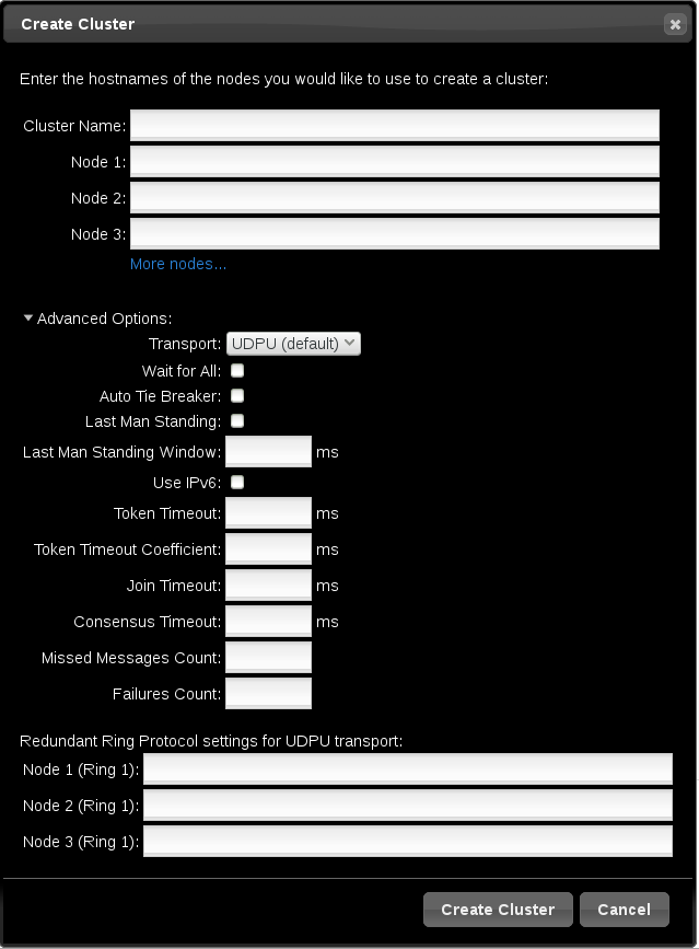
Figure 2.2. Create Clusters page
2.2.2. Setting Cluster Management Permissions
링크 복사링크가 클립보드에 복사되었습니다!
There are two sets of cluster permissions that you can grant to users:
- Permissions for managing the cluster with the Web UI, which also grants permissions to run
pcscommands that connect to nodes over a network. This section describes how to configure those permissions with the Web UI. - Permissions for local users to allow read-only or read-write access to the cluster configuration, using ACLs. Configuring ACLs with the Web UI is described in Section 2.3.4, “Configuring ACLs”.
For further information on user permissions, see Section 4.5, “Setting User Permissions”.
You can grant permission for specific users other than user
hacluster to manage the cluster through the Web UI and to run pcs commands that connect to nodes over a network by adding them to the group haclient. You can then configure the permissions set for an individual member of the group haclient by clicking the tab on the page and setting the permissions on the resulting screen. From this screen, you can also set permissions for groups.
You can grant the following permissions:
- Read permissions, to view the cluster settings
- Write permissions, to modify cluster settings (except for permissions and ACLs)
- Grant permissions, to modify cluster permissions and ACLs
- Full permissions, for unrestricted access to a cluster, including adding and removing nodes, with access to keys and certificates
2.3. Configuring Cluster Components
링크 복사링크가 클립보드에 복사되었습니다!
To configure the components and attributes of a cluster, click on the name of the cluster displayed on the Manage Clusters screen. This brings up the Nodes page, as described in Section 2.3.1, “Cluster Nodes”. This page displays a menu along the top of the page, as shown in Figure 2.3, “Cluster Components Menu”, with the following entries:
- , as described in Section 2.3.1, “Cluster Nodes”
- , as described in Section 2.3.2, “Cluster Resources”
- , as described in Section 2.3.3, “Fence Devices”
- , as described in Section 2.3.4, “Configuring ACLs”
- , as described in Section 2.3.5, “Cluster Properties”

Figure 2.3. Cluster Components Menu
2.3.1. Cluster Nodes
링크 복사링크가 클립보드에 복사되었습니다!
Selecting the
Nodes option from the menu along the top of the cluster management page displays the currently configured nodes and the status of the currently selected node, including which resources are running on the node and the resource location preferences. This is the default page that displays when you select a cluster from the Manage Clusters screen.
You can add or remove nodes from this page, and you can start, stop, restart, or put a node in standby mode. For information on standby mode, see Section 4.4.5, “Standby Mode”.
You can also configure fence devices directly from this page, as described in Section 2.3.3, “Fence Devices”. by selecting
Configure Fencing.
2.3.2. Cluster Resources
링크 복사링크가 클립보드에 복사되었습니다!
Selecting the Resources option from the menu along the top of the cluster management page displays the currently configured resources for the cluster, organized according to resource groups. Selecting a group or a resource displays the attributes of that group or resource.
From this screen, you can add or remove resources, you can edit the configuration of existing resources, and you can create a resource group.
To add a new resource to the cluster, click Add. The brings up the Add Resource screen. When you select a resource type from the dropdown Type menu, the arguments you must specify for that resource appear in the menu. You can click Optional Arguments to display additional arguments you can specify for the resource you are defining. After entering the parameters for the resource you are creating, click .
When configuring the arguments for a resource, a brief description of the argument appears in the menu. If you move the cursor to the field, a longer help description of that argument is displayed.
You can define as resource as a cloned resource, or as a master/slave resource. For information on these resource types, see Chapter 9, Advanced Configuration.
Once you have created at least one resource, you can create a resource group. For information on resource groups, see Section 6.5, “Resource Groups”.
To create a resource group, select a resource that will be part of the group from the Resources screen, then click Create Group. This displays the Create Group screen. Enter a group name and click . This returns you to the Resources screen, which now displays the group name for the resource. After you have created a resource group, you can indicate that group name as a resource parameter when you create or modify additional resources.
2.3.3. Fence Devices
링크 복사링크가 클립보드에 복사되었습니다!
Selecting the Fence Devices option from the menu along the top of the cluster management page displays Fence Devices screen, showing the currently configured fence devices.
To add a new fence device to the cluster, click Add. The brings up the Add Fence Device screen. When you select a fence device type from the drop-down Type menu, the arguments you must specify for that fence device appear in the menu. You can click on Optional Arguments to display additional arguments you can specify for the fence device you are defining. After entering the parameters for the new fence device, click .
For information on configuring fence devices with Pacemaker, see Chapter 5, Fencing: Configuring STONITH.
2.3.4. Configuring ACLs
링크 복사링크가 클립보드에 복사되었습니다!
Selecting the
ACLS option from the menu along the top of the cluster management page displays a screen from which you can set permissions for local users, allowing read-only or read-write access to the cluster configuration by using access control lists (ACLs).
To assign ACL permissions, you create a role and define the access permissions for that role. Each role can have an unlimited number of permissions (read/write/deny) applied to either an XPath query or the ID of a specific element. After defining the role, you can assign it to an existing user or group.
2.3.5. Cluster Properties
링크 복사링크가 클립보드에 복사되었습니다!
Selecting the
Cluster Properties option from the menu along the top of the cluster management page displays the cluster properties and allows you to modify these properties from their default values. For information on the Pacemaker cluster properties, see Chapter 12, Pacemaker Cluster Properties.
2.4. Configuring a High Availability pcsd Web UI
링크 복사링크가 클립보드에 복사되었습니다!
When you use the
pcsd Web UI, you connect to one of the nodes of the cluster to display the cluster management pages. If the node to which you are connecting goes down or becomes unavailable, you can reconnect to the cluster by opening your browser to a URL that specifies a different node of the cluster. It is possible, however, to configure the pcsd Web UI itself for high availability, in which case you can continue to manage the cluster without entering a new URL.
To configure the
pcsd Web UI for high availability, perform the following steps.
- Ensure that
PCSD_SSL_CERT_SYNC_ENABLEDis set totruein the/etc/sysconfig/pcsdconfiguration file, which is the default value in RHEL 7. Enabling certificate syncing causespcsdto sync thepcsdcertificates for the cluster setup and node add commands. - Create an
IPaddr2cluster resource, which is a floating IP address that you will use to connect to thepcsdWeb UI. The IP address must not be one already associated with a physical node. If theIPaddr2resource’s NIC device is not specified, the floating IP must reside on the same network as one of the node’s statically assigned IP addresses, otherwise the NIC device to assign the floating IP address cannot be properly detected. - Create custom SSL certificates for use with
pcsdand ensure that they are valid for the addresses of the nodes used to connect to thepcsdWeb UI.- To create custom SSL certificates, you can use either wildcard certificates or you can use the Subject Alternative Name certificate extension. For information on the Red Hat Certificate System, see the Red Hat Certificate System Administration Guide.
- Install the custom certificates for
pcsdwith thepcs pcsd certkeycommand. - Sync the
pcsdcertificates to all nodes in the cluster with thepcs pcsd sync-certificatescommand.
- Connect to the
pcsdWeb UI using the floating IP address you configured as a cluster resource.
Note
Even when you configure the
pcsd Web UI for high availability, you will be asked to log in again when the node to which you are connecting goes down.
Chapter 3. The pcs Command Line Interface
링크 복사링크가 클립보드에 복사되었습니다!
The
pcs command line interface controls and configures corosync and Pacemaker by providing an interface to the corosync.conf and cib.xml files.
The general format of the
pcs command is as follows.
pcs [-f file] [-h] [commands]...
3.1. The pcs Commands
링크 복사링크가 클립보드에 복사되었습니다!
The
pcs commands are as follows.
clusterConfigure cluster options and nodes. For information on thepcs clustercommand, see Chapter 4, Cluster Creation and Administration.resourceCreate and manage cluster resources. For information on thepcs clustercommand, see Chapter 6, Configuring Cluster Resources, Chapter 8, Managing Cluster Resources, and Chapter 9, Advanced Configuration.stonithConfigure fence devices for use with Pacemaker. For information on thepcs stonithcommand, see Chapter 5, Fencing: Configuring STONITH.constraintManage resource constraints. For information on thepcs constraintcommand, see Chapter 7, Resource Constraints.propertySet Pacemaker properties. For information on setting properties with thepcs propertycommand, see Chapter 12, Pacemaker Cluster Properties.statusView current cluster and resource status. For information on thepcs statuscommand, see Section 3.5, “Displaying Status”.configDisplay complete cluster configuration in user readable form. For information on thepcs configcommand, see Section 3.6, “Displaying the Full Cluster Configuration”.
3.2. pcs Usage Help Display
링크 복사링크가 클립보드에 복사되었습니다!
You can use the
-h option of pcs to display the parameters of a pcs command and a description of those parameters. For example, the following command displays the parameters of the pcs resource command. Only a portion of the output is shown.
# pcs resource -h
Usage: pcs resource [commands]...
Manage pacemaker resources
Commands:
show [resource id] [--all]
Show all currently configured resources or if a resource is specified
show the options for the configured resource. If --all is specified
resource options will be displayed
start <resource id>
Start resource specified by resource_id
...
3.3. Viewing the Raw Cluster Configuration
링크 복사링크가 클립보드에 복사되었습니다!
Although you should not edit the cluster configuration file directly, you can view the raw cluster configuration with the
pcs cluster cib command.
You can save the raw cluster configuration to a specified file with the
pcs cluster cib filename command as described in Section 3.4, “Saving a Configuration Change to a File”.
3.4. Saving a Configuration Change to a File
링크 복사링크가 클립보드에 복사되었습니다!
When using the
pcs command, you can use the -f option to save a configuration change to a file without affecting the active CIB.
If you have previously configured a cluster and there is already an active CIB, you use the following command to save the raw xml file.
pcs cluster cib filename
For example, the following command saves the raw xml from the CIB into a file named
testfile.
# pcs cluster cib testfile
The following command creates a resource in the file
testfile but does not add that resource to the currently running cluster configuration.
# pcs -f testfile resource create VirtualIP ocf:heartbeat:IPaddr2 ip=192.168.0.120 cidr_netmask=24 op monitor interval=30s
You can push the current content of
testfile to the CIB with the following command.
# pcs cluster cib-push testfile3.5. Displaying Status
링크 복사링크가 클립보드에 복사되었습니다!
You can display the status of the cluster and the cluster resources with the following command.
pcs status commands
If you do not specify a commands parameter, this command displays all information about the cluster and the resources. You display the status of only particular cluster components by specifying
resources, groups, cluster, nodes, or pcsd.
3.6. Displaying the Full Cluster Configuration
링크 복사링크가 클립보드에 복사되었습니다!
Use the following command to display the full current cluster configuration.
pcs config
3.7. Displaying The Current pcs Version
링크 복사링크가 클립보드에 복사되었습니다!
The following command displays the current version of
pcs that is running.
pcs --version
3.8. Backing Up and Restoring a Cluster Configuration
링크 복사링크가 클립보드에 복사되었습니다!
As of the Red Hat Enterprise Linux 7.1 release, you can back up the cluster configuration in a tarball with the following command. If you do not specify a file name, the standard output will be used.
pcs config backup filename
Use the following command to restore the cluster configuration files on all cluster nodes from the backup. Specifying the
--local option restores the cluster configuration files only on the node from which you run this command. If you do not specify a file name, the standard input will be used.
pcs config restore [--local] [filename]
Chapter 4. Cluster Creation and Administration
링크 복사링크가 클립보드에 복사되었습니다!
This chapter describes how to perform basic cluster administration with Pacemaker, including creating the cluster, managing the cluster components, and displaying cluster status.
4.1. Cluster Creation
링크 복사링크가 클립보드에 복사되었습니다!
To create a running cluster, perform the following steps:
- Start the
pcsdon each node in the cluster. - Authenticate the nodes that will constitute the cluster.
- Configure and sync the cluster nodes.
- Start cluster services on the cluster nodes.
The following sections described the commands that you use to perform these steps.
4.1.1. Starting the pcsd daemon
링크 복사링크가 클립보드에 복사되었습니다!
The following commands start the
pcsd service and enable pcsd at system start. These commands should be run on each node in the cluster.
# systemctl start pcsd.service
# systemctl enable pcsd.service4.1.2. Authenticating the Cluster Nodes
링크 복사링크가 클립보드에 복사되었습니다!
The following command authenticates
pcs to the pcs daemon on the nodes in the cluster.
- The user name for the
pcsadministrator must behaclusteron every node. It is recommended that the password for userhaclusterbe the same on each node. - If you do not specify
usernameorpassword, the system will prompt you for those parameters for each node when you execute the command. - If you do not specify any nodes, this command will authenticate
pcson the nodes that are specified with apcs cluster setupcommand, if you have previously executed that command.
pcs cluster auth [node] [...] [-u username] [-p password]
For example, the following command authenticates user
hacluster on z1.example.com for both of the nodes in the cluster that consist of z1.example.com and z2.example.com. This command prompts for the password for user hacluster on the cluster nodes.
root@z1 ~]# pcs cluster auth z1.example.com z2.example.com
Username: hacluster
Password:
z1.example.com: Authorized
z2.example.com: Authorized
Authorization tokens are stored in the file
~/.pcs/tokens (or /var/lib/pcsd/tokens).
4.1.3. Configuring and Starting the Cluster Nodes
링크 복사링크가 클립보드에 복사되었습니다!
The following command configures the cluster configuration file and syncs the configuration to the specified nodes.
- If you specify the
--startoption, the command will also start the cluster services on the specified nodes. If necessary, you can also start the cluster services with a separatepcs cluster startcommand.When you create a cluster with thepcs cluster setup --startcommand or when you start cluster services with thepcs cluster startcommand, there may be a slight delay before the cluster is up and running. Before performing any subsequent actions on the cluster and its configuration, it is recommended that you use thepcs cluster statuscommand to be sure that the cluster is up and running. - If you specify the
--localoption, the command will perform changes on the local node only.
pcs cluster setup [--start] [--local] --name cluster_ name node1 [node2] [...]
The following command starts cluster services on the specified node or nodes.
- If you specify the
--alloption, the command starts cluster services on all nodes. - If you do not specify any nodes, cluster services are started on the local node only.
pcs cluster start [--all] [node] [...]
4.2. Configuring Timeout Values for a Cluster
링크 복사링크가 클립보드에 복사되었습니다!
When you create a cluster with the
pcs cluster setup command, timeout values for the cluster are set to default values that should be suitable for most cluster configurations. If you system requires different timeout values, however, you can modify these values with the pcs cluster setup options summarized in Table 4.1, “Timeout Options”
| Option | Description |
|---|---|
--token timeout | Sets time in milliseconds until a token loss is declared after not receiving a token (default 1000 ms) |
--join timeout | sets time in milliseconds to wait for join messages (default 50 ms) |
--consensus timeout | sets time in milliseconds to wait for consensus to be achieved before starting a new round of member- ship configuration (default 1200 ms) |
--miss_count_const count | sets the maximum number of times on receipt of a token a message is checked for retransmission before a retransmission occurs (default 5 messages) |
--fail_recv_const failures | specifies how many rotations of the token without receiving any messages when messages should be received may occur before a new configuration is formed (default 2500 failures) |
For example, the following command creates the cluster
new_cluster and sets the token timeout value to 10000 milliseconds (10 seconds) and the join timeout value to 100 milliseconds.
# pcs cluster setup --name new_cluster nodeA nodeB --token 10000 --join 1004.3. Configuring Redundant Ring Protocol (RRP)
링크 복사링크가 클립보드에 복사되었습니다!
Note
Red Hat supports the configuration of Redundant Ring Protocol (RRP) in clusters subject to the conditions described in the "Redundant Ring Protocol (RRP)" section of Support Policies for RHEL High Availability Clusters - Cluster Interconnect Network Interfaces.
When you create a cluster with the
pcs cluster setup command, you can configure a cluster with Redundant Ring Protocol by specifying both interfaces for each node. When using the default udpu transport, when you specify the cluster nodes you specify the ring 0 address followed by a ',', then the ring 1 address.
For example, the following command configures a cluster named
my_rrp_clusterM with two nodes, node A and node B. Node A has two interfaces, nodeA-0 and nodeA-1. Node B has two interfaces, nodeB-0 and nodeB-1. To configure these nodes as a cluster using RRP, execute the following command.
# pcs cluster setup --name my_rrp_cluster nodeA-0,nodeA-1 nodeB-0,nodeB-1
For information on configuring RRP in a cluster that uses
udp transport, see the help screen for the pcs cluster setup command.
4.4. Managing Cluster Nodes
링크 복사링크가 클립보드에 복사되었습니다!
The following sections describe the commands you use to manage cluster nodes, including commands to start and stop cluster services and to add and remove cluster nodes.
4.4.1. Stopping Cluster Services
링크 복사링크가 클립보드에 복사되었습니다!
The following command stops cluster services on the specified node or nodes. As with the
pcs cluster start, the --all option stops cluster services on all nodes and if you do not specify any nodes, cluster services are stopped on the local node only.
pcs cluster stop [--all] [node] [...]
You can force a stop of cluster services on the local node with the following command, which performs a
kill -9 command.
pcs cluster kill
4.4.2. Enabling and Disabling Cluster Services
링크 복사링크가 클립보드에 복사되었습니다!
Use the following command to configure the cluster services to run on startup on the specified node or nodes.
- If you specify the
--alloption, the command enables cluster services on all nodes. - If you do not specify any nodes, cluster services are enabled on the local node only.
pcs cluster enable [--all] [node] [...]
Use the following command to configure the cluster services not to run on startup on the specified node or nodes.
- If you specify the
--alloption, the command disables cluster services on all nodes. - If you do not specify any nodes, cluster services are disabled on the local node only.
pcs cluster disable [--all] [node] [...]
4.4.3. Adding Cluster Nodes
링크 복사링크가 클립보드에 복사되었습니다!
Note
It is highly recommended that you add nodes to existing clusters only during a production maintenance window. This allows you to perform appropriate resource and deployment testing for the new node and its fencing configuration.
Use the following procedure to add a new node to an existing cluster. In this example, the existing cluster nodes are
clusternode-01.example.com, clusternode-02.example.com, and clusternode-03.example.com. The new node is newnode.example.com.
On the new node to add to the cluster, perform the following tasks.
- Install the cluster packages. If the cluster uses SBD, the Booth ticket manager, or a quorum device, you must manually install the respective packages (
sbd,booth-site,corosync-qdevice) on the new node as well.[root@newnode ~]# yum install -y pcs fence-agents-all - If you are running the
firewallddaemon, execute the following commands to enable the ports that are required by the Red Hat High Availability Add-On.# firewall-cmd --permanent --add-service=high-availability # firewall-cmd --add-service=high-availability - Set a password for the user ID
hacluster. It is recommended that you use the same password for each node in the cluster.[root@newnode ~]# passwd hacluster Changing password for user hacluster. New password: Retype new password: passwd: all authentication tokens updated successfully. - Execute the following commands to start the
pcsdservice and to enablepcsdat system start.# systemctl start pcsd.service # systemctl enable pcsd.service
On a node in the existing cluster, perform the following tasks.
- Authenticate user
haclusteron the new cluster node.[root@clusternode-01 ~]# pcs cluster auth newnode.example.com Username: hacluster Password: newnode.example.com: Authorized - Add the new node to the existing cluster. This command also syncs the cluster configuration file
corosync.confto all nodes in the cluster, including the new node you are adding.[root@clusternode-01 ~]# pcs cluster node add newnode.example.com
On the new node to add to the cluster, perform the following tasks.
- Start and enable cluster services on the new node.
[root@newnode ~]# pcs cluster start Starting Cluster... [root@newnode ~]# pcs cluster enable - Ensure that you configure and test a fencing device for the new cluster node. For information on configuring fencing devices, see Chapter 5, Fencing: Configuring STONITH.
4.4.4. Removing Cluster Nodes
링크 복사링크가 클립보드에 복사되었습니다!
The following command shuts down the specified node and removes it from the cluster configuration file,
corosync.conf, on all of the other nodes in the cluster. For information on removing all information about the cluster from the cluster nodes entirely, thereby destroying the cluster permanently, see Section 4.6, “Removing the Cluster Configuration”.
pcs cluster node remove node4.4.5. Standby Mode
링크 복사링크가 클립보드에 복사되었습니다!
The following command puts the specified node into standby mode. The specified node is no longer able to host resources. Any resources currently active on the node will be moved to another node. If you specify the
--all, this command puts all nodes into standby mode.
You can use this command when updating a resource's packages. You can also use this command when testing a configuration, to simulate recovery without actually shutting down a node.
pcs cluster standby node | --all
The following command removes the specified node from standby mode. After running this command, the specified node is then able to host resources. If you specify the
--all, this command removes all nodes from standby mode.
pcs cluster unstandby node | --all
Note that when you execute the
pcs cluster standby command, this prevents resources from running on the indicated node. When you execute the pcs cluster unstandby command, this allows resources to run on the indicated node. This does not necessarily move the resources back to the indicated node; where the resources can run at that point depends on how you have configured your resources initially. For information on resource constraints, see Chapter 7, Resource Constraints.
4.5. Setting User Permissions
링크 복사링크가 클립보드에 복사되었습니다!
You can grant permission for specific users other than user
hacluster to manage the cluster. There are two sets of permissions that you can grant to individual users:
- Permissions that allow individual users to manage the cluster through the Web UI and to run
pcscommands that connect to nodes over a network, as described in Section 4.5.1, “Setting Permissions for Node Access Over a Network”. Commands that connect to nodes over a network include commands to set up a cluster, or to add or remove nodes from a cluster. - Permissions for local users to allow read-only or read-write access to the cluster configuration, as described in Section 4.5.2, “Setting Local Permissions Using ACLs”. Commands that do not require connecting over a network include commands that edit the cluster configuration, such as those that create resources and configure constraints.
In situations where both sets of permissions have been assigned, the permissions for commands that connect over a network are applied first, and then permissions for editing the cluster configuration on the local node are applied. Most
pcs commands do not require network access and in those cases the network permissions will not apply.
4.5.1. Setting Permissions for Node Access Over a Network
링크 복사링크가 클립보드에 복사되었습니다!
To grant permission for specific users to manage the cluster through the Web UI and to run
pcs commands that connect to nodes over a network, add those users to the group haclient. You can then use the Web UI to grant permissions for those users, as described in Section 2.2.2, “Setting Cluster Management Permissions”.
4.5.2. Setting Local Permissions Using ACLs
링크 복사링크가 클립보드에 복사되었습니다!
As of Red Hat Enterprise Linux 7.1, you can use the
pcs acl command to set permissions for local users to allow read-only or read-write access to the cluster configuration by using access control lists (ACLs). You can also configure ACLs using the pcsd Web UI, as described in Section 2.3.4, “Configuring ACLs”. By default, the root user and any user who is a member of the group haclient has full local read/write access to the cluster configuration.
Setting permissions for local users is a two step process:
- Execute the
pcs acl role create...command to create a role which defines the permissions for that role. - Assign the role you created to a user with the
pcs acl user createcommand.
The following example procedure provides read-only access for a cluster configuration to a local user named
rouser.
- This procedure requires that the user
rouserexists on the local system and that the userrouseris a member of the grouphaclient.# adduser rouser # usermod -a -G haclient rouser - Enable Pacemaker ACLs with the
enable-aclcluster property.# pcs property set enable-acl=true --force - Create a role named
read-onlywith read-only permissions for the cib.# pcs acl role create read-only description="Read access to cluster" read xpath /cib - Create the user
rouserin the pcs ACL system and assign that user theread-onlyrole.# pcs acl user create rouser read-only - View the current ACLs.
# pcs acl
User: rouser
  Roles: read-only
Role: read-only
  Description: Read access to cluster
  Permission: read xpath /cib (read-only-read)
The following example procedure provides write access for a cluster configuration to a local user named
wuser.
- This procedure requires that the user
wuserexists on the local system and that the userwuseris a member of the grouphaclient.# adduser wuser # usermod -a -G haclient wuser - Enable Pacemaker ACLs with the
enable-aclcluster property.# pcs property set enable-acl=true --force - Create a role named
write-accesswith write permissions for the cib.# pcs acl role create write-access description="Full access" write xpath /cib - Create the user
wuserin the pcs ACL system and assign that user thewrite-accessrole.# pcs acl user create wuser write-access - View the current ACLs.
# pcs acl
User: rouser
  Roles: read-only
User: wuser
  Roles: write-access
Role: read-only
  Description: Read access to cluster
  Permission: read xpath /cib (read-only-read)
Role: write-access
  Description: Full Access
  Permission: write xpath /cib (write-access-write)
For further information about cluster ACLs, see the help screen for the
pcs acl command.
4.6. Removing the Cluster Configuration
링크 복사링크가 클립보드에 복사되었습니다!
To remove all cluster configuration files and stop all cluster services, thus permanently destroying a cluster, use the following command.
Warning
This command permanently removes any cluster configuration that has been created. It is recommended that you run
pcs cluster stop before destroying the cluster.
pcs cluster destroy
4.7. Displaying Cluster Status
링크 복사링크가 클립보드에 복사되었습니다!
The following command displays the current status of the cluster and the cluster resources.
pcs status
You can display a subset of information about the current status of the cluster with the following commands.
The following command displays the status of the cluster, but not the cluster resources.
pcs cluster status
The following command displays the status of the cluster resources.
pcs status resources
4.8. Cluster Maintenance
링크 복사링크가 클립보드에 복사되었습니다!
In order to perform maintenance on the nodes of your cluster, you may need to stop or move the resources and services running on that cluster. Or you may need to stop the cluster software while leaving the services untouched. Pacemaker provides a variety of methods for performing system maintenance.
- If you need to stop a node in a cluster while continuing to provide the services running on that cluster on another node, you can put the cluster node in standby mode. A node that is in standby mode is no longer able to host resources. Any resource currently active on the node will be moved to another node, or stopped if no other node is eligible to run the resource.For information on standby mode, see Section 4.4.5, “Standby Mode”.
- If you need to move an individual resource off the node on which it is currently running without stopping that resource, you can use the
pcs resource movecommand to move the resource to a different node. For information on thepcs resource movecommand, see Section 8.1, “Manually Moving Resources Around the Cluster”.When you execute thepcs resource movecommand, this adds a constraint to the resource to prevent it from running on the node on which it is currently running. When you are ready to move the resource back, you can execute thepcs resource clearor thepcs constraint deletecommand to remove the constraint. This does not necessarily move the resources back to the original node, however, since where the resources can run at that point depends on how you have configured your resources initially. You can relocate a resource to a specified node with thepcs resource relocate runcommand, as described in Section 8.1.1, “Moving a Resource from its Current Node”. - If you need to stop a running resource entirely and prevent the cluster from starting it again, you can use the
pcs resource disablecommand. For information on thepcs resource disablecommand, see Section 8.4, “Enabling, Disabling, and Banning Cluster Resources”. - If you want to prevent Pacemaker from taking any action for a resource (for example, if you want to disable recovery actions while performing maintenance on the resource, or if you need to reload the
/etc/sysconfig/pacemakersettings), use thepcs resource unmanagecommand, as described in Section 8.6, “Managed Resources”. Pacemaker Remote connection resources should never be unmanaged. - If you need to put the cluster in a state where no services will be started or stopped, you can set the
maintenance-modecluster property. Putting the cluster into maintenance mode automatically unmanages all resources. For information on setting cluster properties, see Table 12.1, “Cluster Properties”. - If you need to perform maintenance on a Pacemaker remote node, you can remove that node from the cluster by disabling the remote node resource, as described in Section 9.4.8, “System Upgrades and pacemaker_remote”.
Chapter 5. Fencing: Configuring STONITH
링크 복사링크가 클립보드에 복사되었습니다!
STONITH is an acronym for "Shoot The Other Node In The Head" and it protects your data from being corrupted by rogue nodes or concurrent access.
Just because a node is unresponsive, this does not mean it is not accessing your data. The only way to be 100% sure that your data is safe, is to fence the node using STONITH so we can be certain that the node is truly offline, before allowing the data to be accessed from another node.
STONITH also has a role to play in the event that a clustered service cannot be stopped. In this case, the cluster uses STONITH to force the whole node offline, thereby making it safe to start the service elsewhere.
For more complete general information on fencing and its importance in a Red Hat High Availability cluster, see Fencing in a Red Hat High Availability Cluster.
5.1. Available STONITH (Fencing) Agents
링크 복사링크가 클립보드에 복사되었습니다!
Use the following command to view of list of all available STONITH agents. You specify a filter, then this command displays only the STONITH agents that match the filter.
pcs stonith list [filter]
5.2. General Properties of Fencing Devices
링크 복사링크가 클립보드에 복사되었습니다!
Any cluster node can fence any other cluster node with any fence device, regardless of whether the fence resource is started or stopped. Whether the resource is started controls only the recurring monitor for the device, not whether it can be used, with the following exceptions:
- You can disable a fencing device by running the
pcs stonith disable stonith_idcommand. This will prevent any node from using that device - To prevent a specific node from using a fencing device, you can configure location constraints for the fencing resource with the
pcs constraint location ... avoidscommand. - Configuring
stonith-enabled=falsewill disable fencing altogether. Note, however, that Red Hat does not support clusters when fencing is disabled, as it is not suitable for a production environment.
Table 5.1, “General Properties of Fencing Devices” describes the general properties you can set for fencing devices. Refer to Section 5.3, “Displaying Device-Specific Fencing Options” for information on fencing properties you can set for specific fencing devices.
Note
For information on more advanced fencing configuration properties, see Section 5.8, “Additional Fencing Configuration Options”
| Field | Type | Default | Description |
|---|---|---|---|
pcmk_host_map | string | A mapping of host names to port numbers for devices that do not support host names. For example: node1:1;node2:2,3 tells the cluster to use port 1 for node1 and ports 2 and 3 for node2 | |
pcmk_host_list | string | A list of machines controlled by this device (Optional unless pcmk_host_check=static-list). | |
pcmk_host_check | string | dynamic-list | How to determine which machines are controlled by the device. Allowed values: dynamic-list (query the device), static-list (check the pcmk_host_list attribute), none (assume every device can fence every machine) |
5.3. Displaying Device-Specific Fencing Options
링크 복사링크가 클립보드에 복사되었습니다!
Use the following command to view the options for the specified STONITH agent.
pcs stonith describe stonith_agent
For example, the following command displays the options for the fence agent for APC over telnet/SSH.
# pcs stonith describe fence_apc
Stonith options for: fence_apc
  ipaddr (required): IP Address or Hostname
  login (required): Login Name
  passwd: Login password or passphrase
  passwd_script: Script to retrieve password
  cmd_prompt: Force command prompt
  secure: SSH connection
  port (required): Physical plug number or name of virtual machine
  identity_file: Identity file for ssh
  switch: Physical switch number on device
  inet4_only: Forces agent to use IPv4 addresses only
  inet6_only: Forces agent to use IPv6 addresses only
  ipport: TCP port to use for connection with device
  action (required): Fencing Action
  verbose: Verbose mode
  debug: Write debug information to given file
  version: Display version information and exit
  help: Display help and exit
  separator: Separator for CSV created by operation list
  power_timeout: Test X seconds for status change after ON/OFF
  shell_timeout: Wait X seconds for cmd prompt after issuing command
  login_timeout: Wait X seconds for cmd prompt after login
  power_wait: Wait X seconds after issuing ON/OFF
  delay: Wait X seconds before fencing is started
  retry_on: Count of attempts to retry power on
Warning
For fence agents that provide a
method option, a value of cycle is unsupported and should not be specified, as it may cause data corruption.
5.4. Creating a Fencing Device
링크 복사링크가 클립보드에 복사되었습니다!
The following command creates a stonith device.
pcs stonith create stonith_id stonith_device_type [stonith_device_options]
# pcs stonith create MyStonith fence_virt pcmk_host_list=f1 op monitor interval=30s
Some fence devices can fence only a single node, while other devices can fence multiple nodes. The parameters you specify when you create a fencing device depend on what your fencing device supports and requires.
- Some fence devices can automatically determine what nodes they can fence.
- You can use the
pcmk_host_listparameter when creating a fencing device to specify all of the machines that are controlled by that fencing device. - Some fence devices require a mapping of host names to the specifications that the fence device understands. You can map host names with the
pcmk_host_mapparameter when creating a fencing device.
For information on the
pcmk_host_list and pcmk_host_map parameters, see Table 5.1, “General Properties of Fencing Devices”.
After configuring a fence device, it is imperative that you test the device to ensure that it is working correctly. For information on testing fence devices, see Section 5.12, “Testing a Fence Device”.
5.5. Displaying Fencing Devices
링크 복사링크가 클립보드에 복사되었습니다!
The following command shows all currently configured fencing devices. If a stonith_id is specified, the command shows the options for that configured stonith device only. If the
--full option is specified, all configured stonith options are displayed.
pcs stonith show [stonith_id] [--full]
5.6. Modifying and Deleting Fencing Devices
링크 복사링크가 클립보드에 복사되었습니다!
Use the following command to modify or add options to a currently configured fencing device.
pcs stonith update stonith_id [stonith_device_options]
Use the following command to remove a fencing device from the current configuration.
pcs stonith delete stonith_id5.7. Managing Nodes with Fence Devices
링크 복사링크가 클립보드에 복사되었습니다!
You can fence a node manually with the following command. If you specify
--off this will use the off API call to stonith which will turn the node off instead of rebooting it.
pcs stonith fence node [--off]
In a situation where no stonith device is able to fence a node even if it is no longer active, the cluster may not be able to recover the resources on the node. If this occurs, after manually ensuring that the node is powered down you can enter the following command to confirm to the cluster that the node is powered down and free its resources for recovery.
Warning
If the node you specify is not actually off, but running the cluster software or services normally controlled by the cluster, data corruption/cluster failure will occur.
pcs stonith confirm node5.8. Additional Fencing Configuration Options
링크 복사링크가 클립보드에 복사되었습니다!
Table 5.2, “Advanced Properties of Fencing Devices” summarizes additional properties you can set for fencing devices. Note that these properties are for advanced use only.
| Field | Type | Default | Description |
|---|---|---|---|
pcmk_host_argument | string | port | An alternate parameter to supply instead of port. Some devices do not support the standard port parameter or may provide additional ones. Use this to specify an alternate, device-specific, parameter that should indicate the machine to be fenced. A value of none can be used to tell the cluster not to supply any additional parameters. |
pcmk_reboot_action | string | reboot | An alternate command to run instead of reboot. Some devices do not support the standard commands or may provide additional ones. Use this to specify an alternate, device-specific, command that implements the reboot action. |
pcmk_reboot_timeout | time | 60s | Specify an alternate timeout to use for reboot actions instead of stonith-timeout. Some devices need much more/less time to complete than normal. Use this to specify an alternate, device-specific, timeout for reboot actions. |
pcmk_reboot_retries | integer | 2 | The maximum number of times to retry the reboot command within the timeout period. Some devices do not support multiple connections. Operations may fail if the device is busy with another task so Pacemaker will automatically retry the operation, if there is time remaining. Use this option to alter the number of times Pacemaker retries reboot actions before giving up. |
pcmk_off_action | string | off | An alternate command to run instead of off. Some devices do not support the standard commands or may provide additional ones. Use this to specify an alternate, device-specific, command that implements the off action. |
pcmk_off_timeout | time | 60s | Specify an alternate timeout to use for off actions instead of stonith-timeout. Some devices need much more or much less time to complete than normal. Use this to specify an alternate, device-specific, timeout for off actions. |
pcmk_off_retries | integer | 2 | The maximum number of times to retry the off command within the timeout period. Some devices do not support multiple connections. Operations may fail if the device is busy with another task so Pacemaker will automatically retry the operation, if there is time remaining. Use this option to alter the number of times Pacemaker retries off actions before giving up. |
pcmk_list_action | string | list | An alternate command to run instead of list. Some devices do not support the standard commands or may provide additional ones. Use this to specify an alternate, device-specific, command that implements the list action. |
pcmk_list_timeout | time | 60s | Specify an alternate timeout to use for list actions instead of stonith-timeout. Some devices need much more or much less time to complete than normal. Use this to specify an alternate, device-specific, timeout for list actions. |
pcmk_list_retries | integer | 2 | The maximum number of times to retry the list command within the timeout period. Some devices do not support multiple connections. Operations may fail if the device is busy with another task so Pacemaker will automatically retry the operation, if there is time remaining. Use this option to alter the number of times Pacemaker retries list actions before giving up. |
pcmk_monitor_action | string | monitor | An alternate command to run instead of monitor. Some devices do not support the standard commands or may provide additional ones. Use this to specify an alternate, device-specific, command that implements the monitor action. |
pcmk_monitor_timeout | time | 60s | Specify an alternate timeout to use for monitor actions instead of stonith-timeout. Some devices need much more or much less time to complete than normal. Use this to specify an alternate, device-specific, timeout for monitor actions. |
pcmk_monitor_retries | integer | 2 | The maximum number of times to retry the monitor command within the timeout period. Some devices do not support multiple connections. Operations may fail if the device is busy with another task so Pacemaker will automatically retry the operation, if there is time remaining. Use this option to alter the number of times Pacemaker retries monitor actions before giving up. |
pcmk_status_action | string | status | An alternate command to run instead of status. Some devices do not support the standard commands or may provide additional ones. Use this to specify an alternate, device-specific, command that implements the status action. |
pcmk_status_timeout | time | 60s | Specify an alternate timeout to use for status actions instead of stonith-timeout. Some devices need much more or much less time to complete than normal. Use this to specify an alternate, device-specific, timeout for status actions. |
pcmk_status_retries | integer | 2 | The maximum number of times to retry the status command within the timeout period. Some devices do not support multiple connections. Operations may fail if the device is busy with another task so Pacemaker will automatically retry the operation, if there is time remaining. Use this option to alter the number of times Pacemaker retries status actions before giving up. |
pcmk_delay_base | time | 0s |
Enable a base delay for stonith actions and specify a base delay value. In a cluster with an even number of nodes, configuring a delay can help avoid nodes fencing each other at the same time in an even split. A random delay can be useful when the same fence device is used for all nodes, and differing static delays can be useful on each fencing device when a separate device is used for each node. The overall delay is derived from a random delay value adding this static delay so that the sum is kept below the maximum delay. If you set
pcmk_delay_base but do not set pcmk_delay_max, there is no random component to the delay and it will be the value of pcmk_delay_base.
Some individual fence agents implement a "delay" parameter, which is independent of delays configured with a
pcmk_delay_* property. If both of these delays are configured, they are added together and thus would generally not be used in conjunction.
|
pcmk_delay_max | time | 0s |
Enable a random delay for stonith actions and specify the maximum of random delay. In a cluster with an even number of nodes, configuring a delay can help avoid nodes fencing each other at the same time in an even split. A random delay can be useful when the same fence device is used for all nodes, and differing static delays can be useful on each fencing device when a separate device is used for each node. The overall delay is derived from this random delay value adding a static delay so that the sum is kept below the maximum delay. If you set
pcmk_delay_max but do not set pcmk_delay_base there is no static component to the delay.
Some individual fence agents implement a "delay" parameter, which is independent of delays configured with a
pcmk_delay_* property. If both of these delays are configured, they are added together and thus would generally not be used in conjunction.
|
pcmk_action_limit | integer | 1 | The maximum number of actions that can be performed in parallel on this device. The cluster property concurrent-fencing=true needs to be configured first. A value of -1 is unlimited. |
pcmk_on_action | string | on | For advanced use only: An alternate command to run instead of on. Some devices do not support the standard commands or may provide additional ones. Use this to specify an alternate, device-specific, command that implements the on action. |
pcmk_on_timeout | time | 60s | For advanced use only: Specify an alternate timeout to use for on actions instead of stonith-timeout. Some devices need much more or much less time to complete than normal. Use this to specify an alternate, device-specific, timeout for on actions. |
pcmk_on_retries | integer | 2 | For advanced use only: The maximum number of times to retry the on command within the timeout period. Some devices do not support multiple connections. Operations may fail if the device is busy with another task so Pacemaker will automatically retry the operation, if there is time remaining. Use this option to alter the number of times Pacemaker retries on actions before giving up. |
You can determine how a cluster node should react if notified of its own fencing by setting the
fence-reaction cluster property, as decribed in Table 12.1, “Cluster Properties”. A cluster node may receive notification of its own fencing if fencing is misconfigured, or if fabric fencing is in use that does not cut cluster communication. Although the default value for this property is stop, which attempts to immediately stop Pacemaker and keep it stopped, the safest choice for this value is panic, which attempts to immediately reboot the local node. If you prefer the stop behavior, as is most likely to be the case in conjunction with fabric fencing, it is recommended that you set this explicitly.
5.9. Configuring Fencing Levels
링크 복사링크가 클립보드에 복사되었습니다!
Pacemaker supports fencing nodes with multiple devices through a feature called fencing topologies. To implement topologies, create the individual devices as you normally would and then define one or more fencing levels in the fencing topology section in the configuration.
- Each level is attempted in ascending numeric order, starting at 1.
- If a device fails, processing terminates for the current level. No further devices in that level are exercised and the next level is attempted instead.
- If all devices are successfully fenced, then that level has succeeded and no other levels are tried.
- The operation is finished when a level has passed (success), or all levels have been attempted (failed).
Use the following command to add a fencing level to a node. The devices are given as a comma-separated list of stonith ids, which are attempted for the node at that level.
pcs stonith level add level node devices
The following command lists all of the fencing levels that are currently configured.
pcs stonith level
In the following example, there are two fence devices configured for node
rh7-2: an ilo fence device called my_ilo and an apc fence device called my_apc. These commands sets up fence levels so that if the device my_ilo fails and is unable to fence the node, then Pacemaker will attempt to use the device my_apc. This example also shows the output of the pcs stonith level command after the levels are configured.
# pcs stonith level add 1 rh7-2 my_ilo
# pcs stonith level add 2 rh7-2 my_apc
# pcs stonith level
 Node: rh7-2
  Level 1 - my_ilo
  Level 2 - my_apc
The following command removes the fence level for the specified node and devices. If no nodes or devices are specified then the fence level you specify is removed from all nodes.
pcs stonith level remove level [node_id] [stonith_id] ... [stonith_id]
The following command clears the fence levels on the specified node or stonith id. If you do not specify a node or stonith id, all fence levels are cleared.
pcs stonith level clear [node|stonith_id(s)]
If you specify more than one stonith id, they must be separated by a comma and no spaces, as in the following example.
# pcs stonith level clear dev_a,dev_b
The following command verifies that all fence devices and nodes specified in fence levels exist.
pcs stonith level verify
As of Red Hat Enterprise Linux 7.4, you can specify nodes in fencing topology by a regular expression applied on a node name and by a node attribute and its value. For example, the following commands configure nodes
node1, node2, and `node3 to use fence devices apc1 and `apc2, and nodes `node4, node5, and `node6 to use fence devices apc3 and `apc4.
pcs stonith level add 1 "regexp%node[1-3]" apc1,apc2
pcs stonith level add 1 "regexp%node[4-6]" apc3,apc4
The following commands yield the same results by using node attribute matching.
pcs node attribute node1 rack=1
pcs node attribute node2 rack=1
pcs node attribute node3 rack=1
pcs node attribute node4 rack=2
pcs node attribute node5 rack=2
pcs node attribute node6 rack=2
pcs stonith level add 1 attrib%rack=1 apc1,apc2
pcs stonith level add 1 attrib%rack=2 apc3,apc4
5.10. Configuring Fencing for Redundant Power Supplies
링크 복사링크가 클립보드에 복사되었습니다!
When configuring fencing for redundant power supplies, the cluster must ensure that when attempting to reboot a host, both power supplies are turned off before either power supply is turned back on.
If the node never completely loses power, the node may not release its resources. This opens up the possibility of nodes accessing these resources simultaneously and corrupting them.
Prior to Red Hat Enterprise Linux 7.2, you needed to explicitly configure different versions of the devices which used either the 'on' or 'off' actions. Since Red Hat Enterprise Linux 7.2, it is now only required to define each device once and to specify that both are required to fence the node, as in the following example.
# pcs stonith create apc1 fence_apc_snmp ipaddr=apc1.example.com login=user passwd='7a4D#1j!pz864' pcmk_host_map="node1.example.com:1;node2.example.com:2"

# pcs stonith create apc2 fence_apc_snmp ipaddr=apc2.example.com login=user passwd='7a4D#1j!pz864' pcmk_host_map="node1.example.com:1;node2.example.com:2"

# pcs stonith level add 1 node1.example.com apc1,apc2
# pcs stonith level add 1 node2.example.com apc1,apc2
5.11. Configuring ACPI For Use with Integrated Fence Devices
링크 복사링크가 클립보드에 복사되었습니다!
If your cluster uses integrated fence devices, you must configure ACPI (Advanced Configuration and Power Interface) to ensure immediate and complete fencing.
If a cluster node is configured to be fenced by an integrated fence device, disable ACPI Soft-Off for that node. Disabling ACPI Soft-Off allows an integrated fence device to turn off a node immediately and completely rather than attempting a clean shutdown (for example,
shutdown -h now). Otherwise, if ACPI Soft-Off is enabled, an integrated fence device can take four or more seconds to turn off a node (see the note that follows). In addition, if ACPI Soft-Off is enabled and a node panics or freezes during shutdown, an integrated fence device may not be able to turn off the node. Under those circumstances, fencing is delayed or unsuccessful. Consequently, when a node is fenced with an integrated fence device and ACPI Soft-Off is enabled, a cluster recovers slowly or requires administrative intervention to recover.
Note
The amount of time required to fence a node depends on the integrated fence device used. Some integrated fence devices perform the equivalent of pressing and holding the power button; therefore, the fence device turns off the node in four to five seconds. Other integrated fence devices perform the equivalent of pressing the power button momentarily, relying on the operating system to turn off the node; therefore, the fence device turns off the node in a time span much longer than four to five seconds.
- The preferred way to disable ACPI Soft-Off is to change the BIOS setting to "instant-off" or an equivalent setting that turns off the node without delay, as described in Section 5.11.1, “Disabling ACPI Soft-Off with the BIOS”.
Disabling ACPI Soft-Off with the BIOS may not be possible with some systems. If disabling ACPI Soft-Off with the BIOS is not satisfactory for your cluster, you can disable ACPI Soft-Off with one of the following alternate methods:
- Setting
HandlePowerKey=ignorein the/etc/systemd/logind.conffile and verifying that the node node turns off immediately when fenced, as described in Section 5.11.2, “Disabling ACPI Soft-Off in the logind.conf file”. This is the first alternate method of disabling ACPI Soft-Off. - Appending
acpi=offto the kernel boot command line, as described in Section 5.11.3, “Disabling ACPI Completely in the GRUB 2 File”. This is the second alternate method of disabling ACPI Soft-Off, if the preferred or the first alternate method is not available.Important
This method completely disables ACPI; some computers do not boot correctly if ACPI is completely disabled. Use this method only if the other methods are not effective for your cluster.
5.11.1. Disabling ACPI Soft-Off with the BIOS
링크 복사링크가 클립보드에 복사되었습니다!
You can disable ACPI Soft-Off by configuring the BIOS of each cluster node with the following procedure.
Note
The procedure for disabling ACPI Soft-Off with the BIOS may differ among server systems. You should verify this procedure with your hardware documentation.
- Reboot the node and start the
BIOS CMOS Setup Utilityprogram. - Navigate to the menu (or equivalent power management menu).
- At the menu, set the function (or equivalent) to (or the equivalent setting that turns off the node by means of the power button without delay). Example 5.1, “
BIOS CMOS Setup Utility: set to ” shows a menu with set to and set to .Note
The equivalents to , , and may vary among computers. However, the objective of this procedure is to configure the BIOS so that the computer is turned off by means of the power button without delay. - Exit the
BIOS CMOS Setup Utilityprogram, saving the BIOS configuration. - Verify that the node turns off immediately when fenced. For information on testing a fence device, see Section 5.12, “Testing a Fence Device”.
Example 5.1. BIOS CMOS Setup Utility: set to
+---------------------------------------------|-------------------+
|    ACPI Function             [Enabled]      |    Item Help      |
|    ACPI Suspend Type         [S1(POS)]      |-------------------|
|  x Run VGABIOS if S3 Resume   Auto          |   Menu Level   *  |
|    Suspend Mode              [Disabled]     |                   |
|    HDD Power Down            [Disabled]     |                   |
|    Soft-Off by PWR-BTTN      [Instant-Off   |                   |
|    CPU THRM-Throttling       [50.0%]        |                   |
|    Wake-Up by PCI card       [Enabled]      |                   |
|    Power On by Ring          [Enabled]      |                   |
|    Wake Up On LAN            [Enabled]      |                   |
|  x USB KB Wake-Up From S3     Disabled      |                   |
|    Resume by Alarm           [Disabled]     |                   |
|  x  Date(of Month) Alarm       0            |                   |
|  x  Time(hh:mm:ss) Alarm       0 :  0 :     |                   |
|    POWER ON Function         [BUTTON ONLY   |                   |
|  x KB Power ON Password       Enter         |                   |
|  x Hot Key Power ON           Ctrl-F1       |                   |
|                                             |                   |
|                                             |                   |
+---------------------------------------------|-------------------+
This example shows set to , and set to .
5.11.2. Disabling ACPI Soft-Off in the logind.conf file
링크 복사링크가 클립보드에 복사되었습니다!
To disable power-key handing in the
/etc/systemd/logind.conf file, use the following procedure.
- Define the following configuration in the
/etc/systemd/logind.conffile:HandlePowerKey=ignore - Reload the
systemdconfiguration:# systemctl daemon-reload - Verify that the node turns off immediately when fenced. For information on testing a fence device, see Section 5.12, “Testing a Fence Device”.
5.11.3. Disabling ACPI Completely in the GRUB 2 File
링크 복사링크가 클립보드에 복사되었습니다!
You can disable ACPI Soft-Off by appending
acpi=off to the GRUB menu entry for a kernel.
Important
This method completely disables ACPI; some computers do not boot correctly if ACPI is completely disabled. Use this method only if the other methods are not effective for your cluster.
Use the following procedure to disable ACPI in the GRUB 2 file:
- Use the
--argsoption in combination with the--update-kerneloption of thegrubbytool to change thegrub.cfgfile of each cluster node as follows:# grubby --args=acpi=off --update-kernel=ALLFor general information on GRUB 2, see the Working with GRUB 2 chapter in the System Administrator's Guide. - Reboot the node.
- Verify that the node turns off immediately when fenced. For information on testing a fence device, see Section 5.12, “Testing a Fence Device”.
5.12. Testing a Fence Device
링크 복사링크가 클립보드에 복사되었습니다!
Fencing is a fundamental part of the Red Hat Cluster infrastructure and it is therefore important to validate or test that fencing is working properly.
Use the following procedure to test a fence device.
- Use ssh, telnet, HTTP, or whatever remote protocol is used to connect to the device to manually log in and test the fence device or see what output is given. For example, if you will be configuring fencing for an IPMI-enabled device, then try to log in remotely with
ipmitool. Take note of the options used when logging in manually because those options might be needed when using the fencing agent.If you are unable to log in to the fence device, verify that the device is pingable, there is nothing such as a firewall configuration that is preventing access to the fence device, remote access is enabled on the fencing agent, and the credentials are correct. - Run the fence agent manually, using the fence agent script. This does not require that the cluster services are running, so you can perform this step before the device is configured in the cluster. This can ensure that the fence device is responding properly before proceeding.
Note
The examples in this section use thefence_ilofence agent script for an iLO device. The actual fence agent you will use and the command that calls that agent will depend on your server hardware. You should consult the man page for the fence agent you are using to determine which options to specify. You will usually need to know the login and password for the fence device and other information related to the fence device.The following example shows the format you would use to run thefence_ilofence agent script with-o statusparameter to check the status of the fence device interface on another node without actually fencing it. This allows you to test the device and get it working before attempting to reboot the node. When running this command, you specify the name and password of an iLO user that has power on and off permissions for the iLO device.# fence_ilo -a ipaddress -l username -p password -o statusThe following example shows the format you would use to run thefence_ilofence agent script with the-o rebootparameter. Running this command on one node reboots another node on which you have configured the fence agent.# fence_ilo -a ipaddress -l username -p password -o rebootIf the fence agent failed to properly do a status, off, on, or reboot action, you should check the hardware, the configuration of the fence device, and the syntax of your commands. In addition, you can run the fence agent script with the debug output enabled. The debug output is useful for some fencing agents to see where in the sequence of events the fencing agent script is failing when logging into the fence device.# fence_ilo -a ipaddress -l username -p password -o status -D /tmp/$(hostname)-fence_agent.debugWhen diagnosing a failure that has occurred, you should ensure that the options you specified when manually logging in to the fence device are identical to what you passed on to the fence agent with the fence agent script.For fence agents that support an encrypted connection, you may see an error due to certificate validation failing, requiring that you trust the host or that you use the fence agent'sssl-insecureparameter. Similarly, if SSL/TLS is disabled on the target device, you may need to account for this when setting the SSL parameters for the fence agent.Note
If the fence agent that is being tested is afence_drac,fence_ilo, or some other fencing agent for a systems management device that continues to fail, then fall back to tryingfence_ipmilan. Most systems management cards support IPMI remote login and the only supported fencing agent isfence_ipmilan. - Once the fence device has been configured in the cluster with the same options that worked manually and the cluster has been started, test fencing with the
pcs stonith fencecommand from any node (or even multiple times from different nodes), as in the following example. Thepcs stonith fencecommand reads the cluster configuration from the CIB and calls the fence agent as configured to execute the fence action. This verifies that the cluster configuration is correct.# pcs stonith fence node_nameIf thepcs stonith fencecommand works properly, that means the fencing configuration for the cluster should work when a fence event occurs. If the command fails, it means that cluster management cannot invoke the fence device through the configuration it has retrieved. Check for the following issues and update your cluster configuration as needed.- Check your fence configuration. For example, if you have used a host map you should ensure that the system can find the node using the host name you have provided.
- Check whether the password and user name for the device include any special characters that could be misinterpreted by the bash shell. Making sure that you enter passwords and user names surrounded by quotation marks could address this issue.
- Check whether you can connect to the device using the exact IP address or host name you specified in the
pcs stonithcommand. For example, if you give the host name in the stonith command but test by using the IP address, that is not a valid test. - If the protocol that your your fence device uses is accessible to you, use that protocol to try to connect to the device. For example many agents use ssh or telnet. You should try to connect to the device with the credentials you provided when configuring the device, to see if you get a valid prompt and can log in to the device.
If you determine that all your parameters are appropriate but you still have trouble connecting to your fence device, you can check the logging on the fence device itself, if the device provides that, which will show if the user has connected and what command the user issued. You can also search through the/var/log/messagesfile for instances of stonith and error, which could give some idea of what is transpiring, but some agents can provide additional information. - Once the fence device tests are working and the cluster is up and running, test an actual failure. To do this, take an action in the cluster that should initiate a token loss.
- Take down a network. How you take a network depends on your specific configuration. In many cases, you can physically pull the network or power cables out of the host.
Note
Disabling the network interface on the local host rather than physically disconnecting the network or power cables is not recommended as a test of fencing because it does not accurately simulate a typical real-world failure. - Block corosync traffic both inbound and outbound using the local firewall.The following example blocks corosync, assuming the default corosync port is used,
firewalldis used as the local firewall, and the network interface used by corosync is in the default firewall zone:# firewall-cmd --direct --add-rule ipv4 filter OUTPUT 2 -p udp --dport=5405 -j DROP # firewall-cmd --add-rich-rule='rule family="ipv4" port port="5405" protocol="udp" drop' - Simulate a crash and panic your machine with
sysrq-trigger. Note, however, that triggering a kernel panic can cause data loss; it is recommended that you disable your cluster resources first.# echo c > /proc/sysrq-trigger
Chapter 6. Configuring Cluster Resources
링크 복사링크가 클립보드에 복사되었습니다!
This chapter provides information on configuring resources in a cluster.
6.1. Resource Creation
링크 복사링크가 클립보드에 복사되었습니다!
Use the following command to create a cluster resource.
pcs resource create resource_id [standard:[provider:]]type [resource_options] [op operation_action operation_options [operation_action operation options]...] [meta meta_options...] [clone [clone_options] | master [master_options] | --group group_name [--before resource_id | --after resource_id] | [bundle bundle_id] [--disabled] [--wait[=n]]
When you specify the
--group option, the resource is added to the resource group named. If the group does not exist, this creates the group and adds this resource to the group. For information on resource groups, see Section 6.5, “Resource Groups”.
The
--before and --after options specify the position of the added resource relative to a resource that already exists in a resource group.
Specifying the
--disabled option indicates that the resource is not started automatically.
The following command creates a resource with the name
VirtualIP of standard ocf, provider heartbeat, and type IPaddr2. The floating address of this resource is 192.168.0.120, the system will check whether the resource is running every 30 seconds.
# pcs resource create VirtualIP ocf:heartbeat:IPaddr2 ip=192.168.0.120 cidr_netmask=24 op monitor interval=30s
Alternately, you can omit the standard and provider fields and use the following command. This will default to a standard of
ocf and a provider of heartbeat.
# pcs resource create VirtualIP IPaddr2 ip=192.168.0.120 cidr_netmask=24 op monitor interval=30s
Use the following command to delete a configured resource.
pcs resource delete resource_id
For example, the following command deletes an existing resource with a resource ID of
VirtualIP
# pcs resource delete VirtualIP- For information on the resource_id, standard, provider, and type fields of the
pcs resource createcommand, see Section 6.2, “Resource Properties”. - For information on defining resource parameters for individual resources, see Section 6.3, “Resource-Specific Parameters”.
- For information on defining resource meta options, which are used by the cluster to decide how a resource should behave, see Section 6.4, “Resource Meta Options”.
- For information on defining the operations to perform on a resource, see Section 6.6, “Resource Operations”.
- Specifying the
cloneoption creates a clone resource. Specifying themasteroption creates a master/slave resource. For information on resource clones and resources with multiple modes, see Chapter 9, Advanced Configuration.
6.2. Resource Properties
링크 복사링크가 클립보드에 복사되었습니다!
The properties that you define for a resource tell the cluster which script to use for the resource, where to find that script and what standards it conforms to. Table 6.1, “Resource Properties” describes these properties.
| Field | Description |
|---|---|
|
resource_id
| |
|
standard
| |
|
type
| |
|
provider
|
Table 6.2, “Commands to Display Resource Properties”. summarizes the commands that display the available resource properties.
| pcs Display Command | Output |
|---|---|
pcs resource list | Displays a list of all available resources. |
pcs resource standards | Displays a list of available resources agent standards. |
pcs resource providers | Displays a list of available resources agent providers. |
pcs resource list string | Displays a list of available resources filtered by the specified string. You can use this command to display resources filtered by the name of a standard, a provider, or a type. |
6.3. Resource-Specific Parameters
링크 복사링크가 클립보드에 복사되었습니다!
For any individual resource, you can use the following command to display the parameters you can set for that resource.
# pcs resource describe standard:provider:type|type
For example, the following command displays the parameters you can set for a resource of type
LVM.
# pcs resource describe LVM
Resource options for: LVM
  volgrpname (required): The name of volume group.
  exclusive: If set, the volume group will be activated exclusively.
  partial_activation: If set, the volume group will be activated even
  only partial of the physical volumes available. It helps to set to
  true, when you are using mirroring logical volumes.
6.4. Resource Meta Options
링크 복사링크가 클립보드에 복사되었습니다!
In addition to the resource-specific parameters, you can configure additional resource options for any resource. These options are used by the cluster to decide how your resource should behave. Table 6.3, “Resource Meta Options” describes these options.
| Field | Default | Description |
|---|---|---|
priority
| 0
| |
target-role
| Started
|
What state should the cluster attempt to keep this resource in? Allowed values:
* Stopped - Force the resource to be stopped
* Started - Allow the resource to be started (In the case of multistate resources, they will not promoted to master)
|
is-managed
| true
| |
resource-stickiness
|
0
| |
requires
|
Calculated
|
Indicates under what conditions the resource can be started.
Defaults to
fencing except under the conditions noted below. Possible values:
*
nothing - The cluster can always start the resource.
*
quorum - The cluster can only start this resource if a majority of the configured nodes are active. This is the default value if stonith-enabled is false or the resource's standard is stonith.
*
fencing - The cluster can only start this resource if a majority of the configured nodes are active and any failed or unknown nodes have been powered off.
*
unfencing - The cluster can only start this resource if a majority of the configured nodes are active and any failed or unknown nodes have been powered off and only on nodes that have been unfenced. This is the default value if the provides=unfencing stonith meta option has been set for a fencing device.
|
migration-threshold
| INFINITY
|
How many failures may occur for this resource on a node, before this node is marked ineligible to host this resource. A value of 0 indicates that this feature is disabled (the node will never be marked ineligible); by contrast, the cluster treats
INFINITY (the default) as a very large but finite number. This option has an effect only if the failed operation has on-fail=restart (the default), and additionally for failed start operations if the cluster property start-failure-is-fatal is false. For information on configuring the migration-threshold option, see Section 8.2, “Moving Resources Due to Failure”. For information on the start-failure-is-fatal option, see Table 12.1, “Cluster Properties”.
|
failure-timeout
| 0 (disabled)
|
Used in conjunction with the
migration-threshold option, indicates how many seconds to wait before acting as if the failure had not occurred, and potentially allowing the resource back to the node on which it failed. As with any time-based actions, this is not guaranteed to be checked more frequently than the value of the cluster-recheck-interval cluster parameter. For information on configuring the failure-timeout option, see Section 8.2, “Moving Resources Due to Failure”.
|
multiple-active
| stop_start
|
What should the cluster do if it ever finds the resource active on more than one node. Allowed values:
*
block - mark the resource as unmanaged
*
stop_only - stop all active instances and leave them that way
*
stop_start - stop all active instances and start the resource in one location only
|
To change the default value of a resource option, use the following command.
pcs resource defaults options
For example, the following command resets the default value of
resource-stickiness to 100.
# pcs resource defaults resource-stickiness=100
Omitting the options parameter from the
pcs resource defaults displays a list of currently configured default values for resource options. The following example shows the output of this command after you have reset the default value of resource-stickiness to 100.
# pcs resource defaults
resource-stickiness:100
Whether you have reset the default value of a resource meta option or not, you can set a resource option for a particular resource to a value other than the default when you create the resource. The following shows the format of the
pcs resource create command you use when specifying a value for a resource meta option.
pcs resource create resource_id standard:provider:type|type [resource options] [meta meta_options...]
For example, the following command creates a resource with a
resource-stickiness value of 50.
# pcs resource create VirtualIP ocf:heartbeat:IPaddr2 ip=192.168.0.120 cidr_netmask=24 meta resource-stickiness=50
You can also set the value of a resource meta option for an existing resource, group, cloned resource, or master resource with the following command.
pcs resource meta resource_id | group_id | clone_id | master_id meta_options
In the following example, there is an existing resource named
dummy_resource. This command sets the failure-timeout meta option to 20 seconds, so that the resource can attempt to restart on the same node in 20 seconds.
# pcs resource meta dummy_resource failure-timeout=20s
After executing this command, you can display the values for the resource to verity that
failure-timeout=20s is set.
# pcs resource show dummy_resource
 Resource: dummy_resource (class=ocf provider=heartbeat type=Dummy)
  Meta Attrs: failure-timeout=20s
  Operations: start interval=0s timeout=20 (dummy_resource-start-timeout-20)
              stop interval=0s timeout=20 (dummy_resource-stop-timeout-20)
              monitor interval=10 timeout=20 (dummy_resource-monitor-interval-10)
For information on resource clone meta options, see Section 9.1, “Resource Clones”. For information on resource master meta options, see Section 9.2, “Multistate Resources: Resources That Have Multiple Modes”.
6.5. Resource Groups
링크 복사링크가 클립보드에 복사되었습니다!
One of the most common elements of a cluster is a set of resources that need to be located together, start sequentially, and stop in the reverse order. To simplify this configuration, Pacemaker supports the concept of groups.
You create a resource group with the following command, specifying the resources to include in the group. If the group does not exist, this command creates the group. If the group exists, this command adds additional resources to the group. The resources will start in the order you specify them with this command, and will stop in the reverse order of their starting order.
pcs resource group add group_name resource_id [resource_id] ... [resource_id]
[--before resource_id | --after resource_id]
You can use the
--before and --after options of this command to specify the position of the added resources relative to a resource that already exists in the group.
You can also add a new resource to an existing group when you create the resource, using the following command. The resource you create is added to the group named group_name.
pcs resource create resource_id standard:provider:type|type [resource_options] [op operation_action operation_options] --group group_name
You remove a resource from a group with the following command. If there are no resources in the group, this command removes the group itself.
pcs resource group remove group_name resource_id...
The following command lists all currently configured resource groups.
pcs resource group list
The following example creates a resource group named
shortcut that contains the existing resources IPaddr and Email.
# pcs resource group add shortcut IPaddr Email
There is no limit to the number of resources a group can contain. The fundamental properties of a group are as follows.
- Resources are started in the order in which you specify them (in this example,
IPaddrfirst, thenEmail). - Resources are stopped in the reverse order in which you specify them. (
Emailfirst, thenIPaddr).
If a resource in the group cannot run anywhere, then no resource specified after that resource is allowed to run.
- If
IPaddrcannot run anywhere, neither canEmail. - If
Emailcannot run anywhere, however, this does not affectIPaddrin any way.
Obviously as the group grows bigger, the reduced configuration effort of creating resource groups can become significant.
6.5.1. Group Options
링크 복사링크가 클립보드에 복사되었습니다!
A resource group inherits the following options from the resources that it contains:
priority, target-role, is-managed. For information on resource options, see Table 6.3, “Resource Meta Options”.
6.5.2. Group Stickiness
링크 복사링크가 클립보드에 복사되었습니다!
Stickiness, the measure of how much a resource wants to stay where it is, is additive in groups. Every active resource of the group will contribute its stickiness value to the group’s total. So if the default
resource-stickiness is 100, and a group has seven members, five of which are active, then the group as a whole will prefer its current location with a score of 500.
6.6. Resource Operations
링크 복사링크가 클립보드에 복사되었습니다!
To ensure that resources remain healthy, you can add a monitoring operation to a resource's definition. If you do not specify a monitoring operation for a resource, by default the
pcs command will create a monitoring operation, with an interval that is determined by the resource agent. If the resource agent does not provide a default monitoring interval, the pcs command will create a monitoring operation with an interval of 60 seconds.
Table 6.4, “Properties of an Operation” summarizes the properties of a resource monitoring operation.
6.6.1. Configuring Resource Operations
링크 복사링크가 클립보드에 복사되었습니다!
You can configure monitoring operations when you create a resource, using the following command.
pcs resource create resource_id standard:provider:type|type [resource_options] [op operation_action operation_options [operation_type operation_options]...]
For example, the following command creates an
IPaddr2 resource with a monitoring operation. The new resource is called VirtualIP with an IP address of 192.168.0.99 and a netmask of 24 on eth2. A monitoring operation will be performed every 30 seconds.
# pcs resource create VirtualIP ocf:heartbeat:IPaddr2 ip=192.168.0.99 cidr_netmask=24 nic=eth2 op monitor interval=30s
Alternately, you can add a monitoring operation to an existing resource with the following command.
pcs resource op add resource_id operation_action [operation_properties]
Use the following command to delete a configured resource operation.
pcs resource op remove resource_id operation_name operation_propertiesNote
You must specify the exact operation properties to properly remove an existing operation.
To change the values of a monitoring option, you can update the resource. For example, you can create a
VirtualIP with the following command.
# pcs resource create VirtualIP ocf:heartbeat:IPaddr2 ip=192.168.0.99 cidr_netmask=24 nic=eth2
By default, this command creates these operations.
Operations: start interval=0s timeout=20s (VirtualIP-start-timeout-20s)
            stop interval=0s timeout=20s (VirtualIP-stop-timeout-20s)
            monitor interval=10s timeout=20s (VirtualIP-monitor-interval-10s)
To change the stop timeout operation, execute the following command.
# pcs resource update VirtualIP op stop interval=0s timeout=40s

# pcs resource show VirtualIP
 Resource: VirtualIP (class=ocf provider=heartbeat type=IPaddr2)
  Attributes: ip=192.168.0.99 cidr_netmask=24 nic=eth2
  Operations: start interval=0s timeout=20s (VirtualIP-start-timeout-20s)
              monitor interval=10s timeout=20s (VirtualIP-monitor-interval-10s)
              stop interval=0s timeout=40s (VirtualIP-name-stop-interval-0s-timeout-40s)
Note
When you update a resource's operation with the
pcs resource update command, any options you do not specifically call out are reset to their default values.
6.6.2. Configuring Global Resource Operation Defaults
링크 복사링크가 클립보드에 복사되었습니다!
You can use the following command to set global default values for monitoring operations.
pcs resource op defaults [options]
For example, the following command sets a global default of a
timeout value of 240 seconds for all monitoring operations.
# pcs resource op defaults timeout=240s
To display the currently configured default values for monitoring operations, do not specify any options when you execute the
pcs resource op defaults command.
For example, following command displays the default monitoring operation values for a cluster which has been configured with a
timeout value of 240 seconds.
# pcs resource op defaults
timeout: 240s
Note that a cluster resource will use the global default only when the option is not specified in the cluster resource definition. By default, resource agents define the
timeout option for all operations. For the global operation timeout value to be honored, you must create the cluster resource without the timeout option explicitly or you must remove the timeout option by updating the cluster resource, as in the following command.
# pcs resource update VirtualIP op monitor interval=10s
For example, after setting a global default of a
timeout value of 240 seconds for all monitoring operations and updating the cluster resource VirtualIP to remove the timeout value for the monitor operation, the resource VirtualIP will then have timeout values for start, stop, and monitor operations of 20s, 40s and 240s, respectively. The global default value for timeout operations is applied here only on the monitor operation, where the default timeout option was removed by the previous command.
# pcs resource show VirtualIP
 Resource: VirtualIP (class=ocf provider=heartbeat type=IPaddr2)
   Attributes: ip=192.168.0.99 cidr_netmask=24 nic=eth2
   Operations: start interval=0s timeout=20s (VirtualIP-start-timeout-20s)
               monitor interval=10s (VirtualIP-monitor-interval-10s)
               stop interval=0s timeout=40s (VirtualIP-name-stop-interval-0s-timeout-40s)
6.7. Displaying Configured Resources
링크 복사링크가 클립보드에 복사되었습니다!
To display a list of all configured resources, use the following command.
pcs resource show
For example, if your system is configured with a resource named
VirtualIP and a resource named WebSite, the pcs resource show command yields the following output.
# pcs resource show
 VirtualIP	(ocf::heartbeat:IPaddr2):	Started
 WebSite	(ocf::heartbeat:apache):	Started
To display the configured parameters for a resource, use the following command.
pcs resource show resource_id
For example, the following command displays the currently configured parameters for resource
VirtualIP.
# pcs resource show VirtualIP
 Resource: VirtualIP (type=IPaddr2 class=ocf provider=heartbeat)
  Attributes: ip=192.168.0.120 cidr_netmask=24
  Operations: monitor interval=30s
6.8. Modifying Resource Parameters
링크 복사링크가 클립보드에 복사되었습니다!
To modify the parameters of a configured resource, use the following command.
pcs resource update resource_id [resource_options]
The following sequence of commands show the initial values of the configured parameters for resource
VirtualIP, the command to change the value of the ip parameter, and the values following the update command.
# pcs resource show VirtualIP
 Resource: VirtualIP (type=IPaddr2 class=ocf provider=heartbeat)
  Attributes: ip=192.168.0.120 cidr_netmask=24
  Operations: monitor interval=30s
# pcs resource update VirtualIP ip=192.169.0.120
# pcs resource show VirtualIP
 Resource: VirtualIP (type=IPaddr2 class=ocf provider=heartbeat)
  Attributes: ip=192.169.0.120 cidr_netmask=24
  Operations: monitor interval=30s
6.9. Multiple Monitoring Operations
링크 복사링크가 클립보드에 복사되었습니다!
You can configure a single resource with as many monitor operations as a resource agent supports. In this way you can do a superficial health check every minute and progressively more intense ones at higher intervals.
Note
When configuring multiple monitor operations, you must ensure that no two operations are performed at the same interval.
To configure additional monitoring operations for a resource that supports more in-depth checks at different levels, you add an
OCF_CHECK_LEVEL=n option.
For example, if you configure the following
IPaddr2 resource, by default this creates a monitoring operation with an interval of 10 seconds and a timeout value of 20 seconds.
# pcs resource create VirtualIP ocf:heartbeat:IPaddr2 ip=192.168.0.99 cidr_netmask=24 nic=eth2
If the Virtual IP supports a different check with a depth of 10, the following command causes Pacemaker to perform the more advanced monitoring check every 60 seconds in addition to the normal Virtual IP check every 10 seconds. (As noted, you should not configure the additional monitoring operation with a 10-second interval as well.)
# pcs resource op add VirtualIP monitor interval=60s OCF_CHECK_LEVEL=106.10. Enabling and Disabling Cluster Resources
링크 복사링크가 클립보드에 복사되었습니다!
The following command enables the resource specified by
resource_id.
pcs resource enable resource_id
The following command disables the resource specified by
resource_id.
pcs resource disable resource_id6.11. Cluster Resources Cleanup
링크 복사링크가 클립보드에 복사되었습니다!
If a resource has failed, a failure message appears when you display the cluster status. If you resolve that resource, you can clear that failure status with the
pcs resource cleanup command. This command resets the resource status and failcount, telling the cluster to forget the operation history of a resource and re-detect its current state.
The following command cleans up the resource specified by resource_id.
pcs resource cleanup resource_id
If you do not specify a resource_id, this command resets the resource status and
failcountfor all resources.
As of Red Hat Enterprise Linux 7.5, the
pcs resource cleanup command probes only the resources that display as a failed action. To probe all resources on all nodes you can enter the following command:
pcs resource refresh
By default, the
pcs resource refresh command probes only the nodes where a resource's state is known. To probe all resources even if the state is not known, enter the following command:
pcs resource refresh --full
Chapter 7. Resource Constraints
링크 복사링크가 클립보드에 복사되었습니다!
You can determine the behavior of a resource in a cluster by configuring constraints for that resource. You can configure the following categories of constraints:
locationconstraints — A location constraint determines which nodes a resource can run on. Location constraints are described in Section 7.1, “Location Constraints”.orderconstraints — An order constraint determines the order in which the resources run. Order constraints are described in Section 7.2, “Order Constraints”.colocationconstraints — A colocation constraint determines where resources will be placed relative to other resources. Colocation constraints are described in Section 7.3, “Colocation of Resources”.
As a shorthand for configuring a set of constraints that will locate a set of resources together and ensure that the resources start sequentially and stop in reverse order, Pacemaker supports the concept of resource groups. For information on resource groups, see Section 6.5, “Resource Groups”.
7.1. Location Constraints
링크 복사링크가 클립보드에 복사되었습니다!
Location constraints determine which nodes a resource can run on. You can configure location constraints to determine whether a resource will prefer or avoid a specified node.
In addition to location constraints, the node on which a resource runs is influenced by the
resource-stickiness value for that resource, which determines to what degree a resource prefers to remain on the node where it is currently running. For information on setting the resource-stickiness value, see Section 7.1.5, “Configuring a Resource to Prefer its Current Node”.
7.1.1. Basic Location Constraints
링크 복사링크가 클립보드에 복사되었습니다!
You can configure a basic location constraint to specify whether a resource prefers or avoid a node, with an optional
score value to indicate the relative degree of preference for the constraint.
The following command creates a location constraint for a resource to prefer the specified node or nodes. Note that it is possible to create constraints on a particular resource for more than one node with a single command.
pcs constraint location rsc prefers node[=score] [node[=score]] ...
The following command creates a location constraint for a resource to avoid the specified node or nodes.
pcs constraint location rsc avoids node[=score] [node[=score]] ...
Table 7.1, “Simple Location Constraint Options” summarizes the meanings of the options for configuring location constraints in their simplest form.
| Field | Description |
|---|---|
rsc
|
A resource name
|
node
|
A node’s name
|
score
|
Postive integer value to indicate the preference for whether a resource should prefer or avoid a node.
INFINITY is the default score value for a resource location constraint.
A value of
INFINITY for score in a pcs contraint location rsc prefers command indicates that the resource will prefer that node if the node is available, but does not prevent the resource from running on another node if the specified node is unavailable.
A value of
INFINITY for score in a pcs contraint location rsc avoids command indicates that the resource will never run on that node, even if no other node is available. This is the equivalent of setting a pcs constraint location add command with a score of -INFINITY.
|
The following command creates a location constraint to specify that the resource
Webserver prefers node node1.
# pcs constraint location Webserver prefers node1
As of Red Hat Enterprise Linux 7.4,
pcs supports regular expressions in location constraints on the command line. These constraints apply to multiple resources based on the regular expression matching resource name. This allows you to configure multiple location contraints with a single command line.
The following command creates a location constraint to specify that resources
dummy0 to dummy9 prefer node1.
# pcs constraint location 'regexp%dummy[0-9]' prefers node1
Since Pacemaker uses POSIX extended regular expressions as documented at http://pubs.opengroup.org/onlinepubs/9699919799/basedefs/V1_chap09.html#tag_09_04, you can specify the same constraint with the following command.
# pcs constraint location 'regexp%dummy[[:digit:]]' prefers node17.1.2. Advanced Location Constraints
링크 복사링크가 클립보드에 복사되었습니다!
When configuring a location constraint on a node, you can use the
resource-discovery option of the pcs constraint location command to indicate a preference for whether Pacemaker should perform resource discovery on this node for the specified resource. Limiting resource discovery to a subset of nodes the resource is physically capable of running on can significantly boost performance when a large set of nodes is present. When pacemaker_remote is in use to expand the node count into the hundreds of nodes range, this option should be considered.
The following command shows the format for specifying the
resource-discovery option of the pcs constraint location command. Note that id is the constraint id. The meanings of rsc, node, and score are summarized in Table 7.1, “Simple Location Constraint Options”. In this command, a positive value for score corresponds to a basic location`constraint that configures a resource to prefer a node, while a negative value for score corresponds to a basic location`constraint that configures a resource to avoid a node. As with basic location constraints, you can use regular expressions for resources with these constraints as well.
pcs constraint location add id rsc node score [resource-discovery=option]
Table 7.2, “Resource Discovery Values” summarizes the meanings of the values you can specify for the
resource-discovery option.
| Value | Description |
|---|---|
always
|
Always perform resource discovery for the specified resource on this node. This is the default
resource-discovery value for a resource location constraint.
|
never
|
Never perform resource discovery for the specified resource on this node.
|
exclusive
|
Perform resource discovery for the specified resource only on this node (and other nodes similarly marked as
exclusive). Multiple location constraints using exclusive discovery for the same resource across different nodes creates a subset of nodes resource-discovery is exclusive to. If a resource is marked for exclusive discovery on one or more nodes, that resource is only allowed to be placed within that subset of nodes.
|
Note that setting the
resource-discovery option to never or exclusive allows the possibility for the resource to be active in those locations without the cluster’s knowledge. This can lead to the resource being active in more than one location if the service is started outside the cluster's control (for example, by systemd or by an administrator). This can also occur if the resource-discovery property is changed while part of the cluster is down or suffering split-brain, or if the resource-discovery property is changed for a resource and node while the resource is active on that node. For this reason, using this option is appropriate only when you have more than eight nodes and there is a way to guarantee that the resource can run only in a particular location (for example, when the required software is not installed anywhere else).
7.1.3. Using Rules to Determine Resource Location
링크 복사링크가 클립보드에 복사되었습니다!
For more complicated location constraints, you can use Pacemaker rules to determine a resource's location. For general information about Pacemaker rules and the properties you can set, see Chapter 11, Pacemaker Rules.
Use the following command to configure a Pacemaker constraint that uses rules. If
score is omitted, it defaults to INFINITY. If resource-discovery is omitted, it defaults to always. For information on the resource-discovery option, see Section 7.1.2, “Advanced Location Constraints”. As with basic location constraints, you can use regular expressions for resources with these constraints as well.
When using rules to configure location constraints, the value of
score can be positive or negative, with a positive value indicating "prefers" and a negative value indicating "avoids".
pcs constraint location rsc rule [resource-discovery=option] [role=master|slave] [score=score | score-attribute=attribute] expression
The expression option can be one of the following where duration_options and date_spec_options are: hours, monthdays, weekdays, yeardays, months, weeks, years, weekyears, moon as described in Table 11.5, “Properties of a Date Specification”.
defined|not_defined attributeattribute lt|gt|lte|gte|eq|ne [string|integer|version] valuedate gt|lt datedate in-range date to datedate in-range date to duration duration_options ...date-spec date_spec_optionsexpression and|or expression(expression)
The following location constraint configures an expression that is true if now is any time in the year 2018.
# pcs constraint location Webserver rule score=INFINITY date-spec years=2018
The following command configures an expression that is true from 9 am to 5 pm, Monday through Friday. Note that the hours value of 16 matches up to 16:59:59, as the numeric value (hour) still matches.
# pcs constraint location Webserver rule score=INFINITY date-spec hours="9-16" weekdays="1-5"
The following command configures an expression that is true when there is a full moon on Friday the thirteenth.
# pcs constraint location Webserver rule date-spec weekdays=5 monthdays=13 moon=47.1.4. Location Constraint Strategy
링크 복사링크가 클립보드에 복사되었습니다!
Using any of the location constraints described in Section 7.1.1, “Basic Location Constraints”, Section 7.1.2, “Advanced Location Constraints”, and Section 7.1.3, “Using Rules to Determine Resource Location” you can configure a general strategy for specifying which nodes a resources can run on:
- Opt-In Clusters — Configure a cluster in which, by default, no resource can run anywhere and then selectively enable allowed nodes for specific resources. The procedure for configuring an opt-in cluster is described in Section 7.1.4.1, “Configuring an "Opt-In" Cluster”.
- Opt-Out Clusters — Configure a cluster in which, by default, all resources can run anywhere and then create location constraints for resources that are not allowed to run on specific nodes. The procedure for configuring an opt-out cluster is described in Section 7.1.4.2, “Configuring an "Opt-Out" Cluster”. This is the default Pacemaker strategy.
Whether you should choose to configure your cluster as an opt-in or opt-out cluster depends both on your personal preference and the make-up of your cluster. If most of your resources can run on most of the nodes, then an opt-out arrangement is likely to result in a simpler configuration. On the other hand, if most resources can only run on a small subset of nodes an opt-in configuration might be simpler.
7.1.4.1. Configuring an "Opt-In" Cluster
링크 복사링크가 클립보드에 복사되었습니다!
To create an opt-in cluster, set the
symmetric-cluster cluster property to false to prevent resources from running anywhere by default.
# pcs property set symmetric-cluster=false
Enable nodes for individual resources. The following commands configure location constraints so that the resource
Webserver prefers node example-1, the resource Database prefers node example-2, and both resources can fail over to node example-3 if their preferred node fails. When configuring location constraints for an opt-in cluster, setting a score of zero allows a resource to run on a node without indicating any preference to prefer or avoid the node.
# pcs constraint location Webserver prefers example-1=200
# pcs constraint location Webserver prefers example-3=0
# pcs constraint location Database prefers example-2=200
# pcs constraint location Database prefers example-3=0
7.1.4.2. Configuring an "Opt-Out" Cluster
링크 복사링크가 클립보드에 복사되었습니다!
To create an opt-out cluster, set the
symmetric-cluster cluster property to true to allow resources to run everywhere by default.
# pcs property set symmetric-cluster=true
The following commands will then yield a configuration that is equivalent to the example in Section 7.1.4.1, “Configuring an "Opt-In" Cluster”. Both resources can fail over to node
example-3 if their preferred node fails, since every node has an implicit score of 0.
# pcs constraint location Webserver prefers example-1=200
# pcs constraint location Webserver avoids example-2=INFINITY
# pcs constraint location Database avoids example-1=INFINITY
# pcs constraint location Database prefers example-2=200
Note that it is not necessary to specify a score of INFINITY in these commands, since that is the default value for the score.
7.1.5. Configuring a Resource to Prefer its Current Node
링크 복사링크가 클립보드에 복사되었습니다!
Resources have a
resource-stickiness value that you can set as a meta attribute when you create the resource, as described in Section 6.4, “Resource Meta Options”. The resource-stickiness value determines how much a resource wants to remain on the node where it is currently running. Pacemaker considers the resource-stickiness value in conjunction with other settings (for example, the score values of location constraints) to determine whether to move a resource to another node or to leave it in place.
By default, a resource is created with a
resource-stickiness value of 0. Pacemaker’s default behavior when resource-stickiness is set to 0 and there are no location constraints is to move resources so that they are evenly distributed among the cluster nodes. This may result in healthy resources moving more often than you desire. To prevent this behavior, you can set the default resource-stickiness value to 1. This default will apply to all resources in the cluster. This small value can be easily overridden by other constraints that you create, but it is enough to prevent Pacemaker from needlessly moving healthy resources around the cluster.
The following command sets the default resource-stickiness value to 1.
# pcs resource defaults resource-stickiness=1
If the
resource-stickiness value is set, then no resources will move to a newly-added node. If resource balancing is desired at that point, you can temporarily set the resource-stickiness value back to 0.
Note that if a location constraint score is higher than the resource-stickiness value, the cluster may still move a healthy resource to the node where the location constraint points.
For further information about how Pacemaker determines where to place a resource, see Section 9.6, “Utilization and Placement Strategy”.
7.2. Order Constraints
링크 복사링크가 클립보드에 복사되었습니다!
Order constraints determine the order in which the resources run.
Use the following command to configure an order constraint.
pcs constraint order [action] resource_id then [action] resource_id [options]
Table 7.3, “Properties of an Order Constraint”. summarizes the properties and options for configuring order constraints.
| Field | Description |
|---|---|
|
resource_id
|
The name of a resource on which an action is performed.
|
|
action
|
The action to perform on a resource. Possible values of the action property are as follows:
*
start - Start the resource.
*
stop - Stop the resource.
*
promote - Promote the resource from a slave resource to a master resource.
*
demote - Demote the resource from a master resource to a slave resource.
If no action is specified, the default action is
start. For information on master and slave resources, see Section 9.2, “Multistate Resources: Resources That Have Multiple Modes”.
|
kind option
|
How to enforce the constraint. The possible values of the
kind option are as follows:
*
Optional - Only applies if both resources are executing the specified action. For information on optional ordering, see Section 7.2.2, “Advisory Ordering”.
*
Mandatory - Always (default value). If the first resource you specified is stopping or cannot be started, the second resource you specified must be stopped. For information on mandatory ordering, see Section 7.2.1, “Mandatory Ordering”.
*
Serialize - Ensure that no two stop/start actions occur concurrently for a set of resources.
|
symmetrical option
|
7.2.1. Mandatory Ordering
링크 복사링크가 클립보드에 복사되었습니다!
A mandatory constraints indicates that the second resource you specify cannot run without the first resource you specify being active. This is the default value of the
kind option. Leaving the default value ensures that the second resource you specify will react when the first resource you specify changes state.
- If the first resource you specified was running and is stopped, the second resource you specified will also be stopped (if it is running).
- If the first resource you specified resource was not running and cannot be started, the resource you specified will be stopped (if it is running).
- If the first resource you specified is (re)started while the second resource you specified is running, the second resource you specified will be stopped and restarted.
Note, however, that the cluster reacts to each state change. If the first resource is restarted and is in a started state again before the second resource initiated a stop operation, the second resource will not need to be restarted.
7.2.2. Advisory Ordering
링크 복사링크가 클립보드에 복사되었습니다!
When the
kind=Optional option is specified for an order constraint, the constraint is considered optional and only applies if both resources are executing the specified actions. Any change in state by the first resource you specify will have no effect on the second resource you specify.
The following command configures an advisory ordering constraint for the resources named
VirtualIP and dummy_resource.
# pcs constraint order VirtualIP then dummy_resource kind=Optional 7.2.3. Ordered Resource Sets
링크 복사링크가 클립보드에 복사되었습니다!
A common situation is for an administrator to create a chain of ordered resources, where, for example, resource A starts before resource B which starts before resource C. If your configuration requires that you create a set of resources that is colocated and started in order, you can configure a resource group that contains those resources, as described in Section 6.5, “Resource Groups”. There are some situations, however, where configuring the resources that need to start in a specified order as a resource group is not appropriate:
- You may need to configure resources to start in order and the resources are not necessarily colocated.
- You may have a resource C that must start after either resource A or B has started but there is no relationship between A and B.
- You may have resources C and D that must start after both resources A and B have started, but there is no relationship between A and B or between C and D.
In these situations, you can create an order constraint on a set or sets of resources with the
pcs constraint order set command.
You can set the following options for a set of resources with the
pcs constraint order set command.
sequential, which can be set totrueorfalseto indicate whether the set of resources must be ordered relative to each other.Settingsequentialtofalseallows a set to be ordered relative to other sets in the ordering constraint, without its members being ordered relative to each other. Therefore, this option makes sense only if multiple sets are listed in the constraint; otherwise, the constraint has no effect.require-all, which can be set totrueorfalseto indicate whether all of the resources in the set must be active before continuing. Settingrequire-alltofalsemeans that only one resource in the set needs to be started before continuing on to the next set. Settingrequire-alltofalsehas no effect unless used in conjunction with unordered sets, which are sets for whichsequentialis set tofalse.action, which can be set tostart,promote,demoteorstop, as described in Table 7.3, “Properties of an Order Constraint”.
You can set the following constraint options for a set of resources following the
setoptions parameter of the pcs constraint order set command.
id, to provide a name for the constraint you are defining.score, to indicate the degree of preference for this constraint. For information on this option, see Table 7.4, “Properties of a Colocation Constraint”.
pcs constraint order set resource1 resource2 [resourceN]... [options] [set resourceX resourceY ... [options]] [setoptions [constraint_options]]
If you have three resources named
D1, D2, and D3, the following command configures them as an ordered resource set.
# pcs constraint order set D1 D2 D37.2.4. Removing Resources From Ordering Constraints
링크 복사링크가 클립보드에 복사되었습니다!
Use the following command to remove resources from any ordering constraint.
pcs constraint order remove resource1 [resourceN]...
7.3. Colocation of Resources
링크 복사링크가 클립보드에 복사되었습니다!
A colocation constraint determines that the location of one resource depends on the location of another resource.
There is an important side effect of creating a colocation constraint between two resources: it affects the order in which resources are assigned to a node. This is because you cannot place resource A relative to resource B unless you know where resource B is. So when you are creating colocation constraints, it is important to consider whether you should colocate resource A with resource B or resource B with resource A.
Another thing to keep in mind when creating colocation constraints is that, assuming resource A is colocated with resource B, the cluster will also take into account resource A's preferences when deciding which node to choose for resource B.
The following command creates a colocation constraint.
pcs constraint colocation add [master|slave] source_resource with [master|slave] target_resource [score] [options]
For information on master and slave resources, see Section 9.2, “Multistate Resources: Resources That Have Multiple Modes”.
Table 7.4, “Properties of a Colocation Constraint”. summarizes the properties and options for configuring colocation constraints.
| Field | Description |
|---|---|
|
source_resource
|
The colocation source. If the constraint cannot be satisfied, the cluster may decide not to allow the resource to run at all.
|
|
target_resource
|
The colocation target. The cluster will decide where to put this resource first and then decide where to put the source resource.
|
|
score
|
Positive values indicate the resource should run on the same node. Negative values indicate the resources should not run on the same node. A value of +
INFINITY, the default value, indicates that the source_resource must run on the same node as the target_resource. A value of -INFINITY indicates that the source_resource must not run on the same node as the target_resource.
|
7.3.1. Mandatory Placement
링크 복사링크가 클립보드에 복사되었습니다!
Mandatory placement occurs any time the constraint's score is
+INFINITY or -INFINITY. In such cases, if the constraint cannot be satisfied, then the source_resource is not permitted to run. For score=INFINITY, this includes cases where the target_resource is not active.
If you need
myresource1 to always run on the same machine as myresource2, you would add the following constraint:
# pcs constraint colocation add myresource1 with myresource2 score=INFINITY
Because
INFINITY was used, if myresource2 cannot run on any of the cluster nodes (for whatever reason) then myresource1 will not be allowed to run.
Alternatively, you may want to configure the opposite, a cluster in which
myresource1 cannot run on the same machine as myresource2. In this case use score=-INFINITY
# pcs constraint colocation add myresource1 with myresource2 score=-INFINITY
Again, by specifying
-INFINITY, the constraint is binding. So if the only place left to run is where myresource2 already is, then myresource1 may not run anywhere.
7.3.2. Advisory Placement
링크 복사링크가 클립보드에 복사되었습니다!
If mandatory placement is about "must" and "must not", then advisory placement is the "I would prefer if" alternative. For constraints with scores greater than
-INFINITY and less than INFINITY, the cluster will try to accommodate your wishes but may ignore them if the alternative is to stop some of the cluster resources. Advisory colocation constraints can combine with other elements of the configuration to behave as if they were mandatory.
7.3.3. Colocating Sets of Resources
링크 복사링크가 클립보드에 복사되었습니다!
If your configuration requires that you create a set of resources that is colocated and started in order, you can configure a resource group that contains those resources, as described in Section 6.5, “Resource Groups”. There are some situations, however, where configuring the resources that need to be colocated as a resource group is not appropriate:
- You may need to colocate a set of resources but the resources do not necessarily need to start in order.
- You may have a resource C that must be colocated with either resource A or B has started but there is no relationship between A and B.
- You may have resources C and D that must be colocated with both resources A and B, but there is no relationship between A and B or between C and D.
In these situations, you can create a colocation constraint on a set or sets of resources with the
pcs constraint colocation set command.
You can set the following options for a set of resources with the
pcs constraint colocation set command.
sequential, which can be set totrueorfalseto indicate whether the members of the set must be colocated with each other.Settingsequentialtofalseallows the members of this set to be colocated with another set listed later in the constraint, regardless of which members of this set are active. Therefore, this option makes sense only if another set is listed after this one in the constraint; otherwise, the constraint has no effect.role, which can be set toStopped,Started,Master, orSlave. For information on multistate resources, see Section 9.2, “Multistate Resources: Resources That Have Multiple Modes”.
You can set the following constraint options for a set of resources following the
setoptions parameter of the pcs constraint colocation set command.
kind, to indicate how to enforce the constraint. For information on this option, see Table 7.3, “Properties of an Order Constraint”.symmetrical, to indicate the order in which to stop the resources. If true, which is the default, stop the resources in the reverse order. Default value:trueid, to provide a name for the constraint you are defining.
When listing members of a set, each member is colocated with the one before it. For example, "set A B" means "B is colocated with A". However, when listing multiple sets, each set is colocated with the one after it. For example, "set C D sequential=false set A B" means "set C D (where C and D have no relation between each other) is colocated with set A B (where B is colocated with A)".
The following command creates a colocation constraint on a set or sets of resources.
pcs constraint colocation set resource1 resource2 [resourceN]... [options] [set resourceX resourceY ... [options]] [setoptions [constraint_options]]
7.3.4. Removing Colocation Constraints
링크 복사링크가 클립보드에 복사되었습니다!
Use the following command to remove colocation constraints with source_resource.
pcs constraint colocation remove source_resource target_resource7.4. Displaying Constraints
링크 복사링크가 클립보드에 복사되었습니다!
There are a several commands you can use to display constraints that have been configured.
The following command lists all current location, order, and colocation constraints.
pcs constraint list|show
The following command lists all current location constraints.
- If
resourcesis specified, location constraints are displayed per resource. This is the default behavior. - If
nodesis specified, location constraints are displayed per node. - If specific resources or nodes are specified, then only information about those resources or nodes is displayed.
pcs constraint location [show resources|nodes [specific nodes|resources]] [--full]
The following command lists all current ordering constraints. If the
--full option is specified, show the internal constraint IDs.
pcs constraint order show [--full]
The following command lists all current colocation constraints. If the
--full option is specified, show the internal constraint IDs.
pcs constraint colocation show [--full]
The following command lists the constraints that reference specific resources.
pcs constraint ref resource ...
Chapter 8. Managing Cluster Resources
링크 복사링크가 클립보드에 복사되었습니다!
This chapter describes various commands you can use to manage cluster resources. It provides information on the following procedures.
8.1. Manually Moving Resources Around the Cluster
링크 복사링크가 클립보드에 복사되었습니다!
You can override the cluster and force resources to move from their current location. There are two occasions when you would want to do this:
- When a node is under maintenance, and you need to move all resources running on that node to a different node
- When individually specified resources needs to be moved
To move all resources running on a node to a different node, you put the node in standby mode. For information on putting a cluster node in standby node, see Section 4.4.5, “Standby Mode”.
You can move individually specified resources in either of the following ways.
- You can use the
pcs resource movecommand to move a resource off a node on which it is currently running, as described in Section 8.1.1, “Moving a Resource from its Current Node”. - You can use the
pcs resource relocate runcommand to move a resource to its preferred node, as determined by current cluster status, constraints, location of resources and other settings. For information on this command, see Section 8.1.2, “Moving a Resource to its Preferred Node”.
8.1.1. Moving a Resource from its Current Node
링크 복사링크가 클립보드에 복사되었습니다!
To move a resource off the node on which it is currently running, use the following command, specifying the resource_id of the resource as defined. Specify the
destination_node if you want to indicate on which node to run the resource that you are moving.
pcs resource move resource_id [destination_node] [--master] [lifetime=lifetime]
Note
When you execute the
pcs resource move command, this adds a constraint to the resource to prevent it from running on the node on which it is currently running. You can execute the pcs resource clear or the pcs constraint delete command to remove the constraint. This does not necessarily move the resources back to the original node; where the resources can run at that point depends on how you have configured your resources initially.
If you specify the
--master parameter of the pcs resource move command, the scope of the constraint is limited to the master role and you must specify master_id rather than resource_id.
You can optionally configure a
lifetime parameter for the pcs resource move command to indicate a period of time the constraint should remain. You specify the units of a lifetime parameter according to the format defined in ISO 8601, which requires that you specify the unit as a capital letter such as Y (for years), M (for months), W (for weeks), D (for days), H (for hours), M (for minutes), and S (for seconds).
To distinguish a unit of minutes(M) from a unit of months(M), you must specify PT before indicating the value in minutes. For example, a
lifetime parameter of 5M indicates an interval of five months, while a lifetime parameter of PT5M indicates an interval of five minutes.
The
lifetime parameter is checked at intervals defined by the cluster-recheck-interval cluster property. By default this value is 15 minutes. If your configuration requires that you check this parameter more frequently, you can reset this value with the following command.
pcs property set cluster-recheck-interval=value
You can optionally configure a
--wait[=n] parameter for the pcs resource move command to indicate the number of seconds to wait for the resource to start on the destination node before returning 0 if the resource is started or 1 if the resource has not yet started. If you do not specify n, the default resource timeout will be used.
The following command moves the resource
resource1 to node example-node2 and prevents it from moving back to the node on which it was originally running for one hour and thirty minutes.
pcs resource move resource1 example-node2 lifetime=PT1H30M
The following command moves the resource
resource1 to node example-node2 and prevents it from moving back to the node on which it was originally running for thirty minutes.
pcs resource move resource1 example-node2 lifetime=PT30M
For information on resource constraints, see Chapter 7, Resource Constraints.
8.1.2. Moving a Resource to its Preferred Node
링크 복사링크가 클립보드에 복사되었습니다!
After a resource has moved, either due to a failover or to an administrator manually moving the node, it will not necessarily move back to its original node even after the circumstances that caused the failover have been corrected. To relocate resources to their preferred node, use the following command. A preferred node is determined by the current cluster status, constraints, resource location, and other settings and may change over time.
pcs resource relocate run [resource1] [resource2] ...
If you do not specify any resources, all resource are relocated to their preferred nodes.
This command calculates the preferred node for each resource while ignoring resource stickiness. After calculating the preferred node, it creates location constraints which will cause the resources to move to their preferred nodes. Once the resources have been moved, the constraints are deleted automatically. To remove all constraints created by the
pcs resource relocate run command, you can enter the pcs resource relocate clear command. To display the current status of resources and their optimal node ignoring resource stickiness, enter the pcs resource relocate show command.
8.2. Moving Resources Due to Failure
링크 복사링크가 클립보드에 복사되었습니다!
When you create a resource, you can configure the resource so that it will move to a new node after a defined number of failures by setting the
migration-threshold option for that resource. Once the threshold has been reached, this node will no longer be allowed to run the failed resource until:
- The administrator manually resets the resource's
failcountusing thepcs resource failcountcommand. - The resource's
failure-timeoutvalue is reached.
The value of
migration-threshold is set to INFINITY by default. INFINITY is defined internally as a very large but finite number. A value of 0 disables the migration-threshold feature.
Note
Setting a
migration-threshold for a resource is not the same as configuring a resource for migration, in which the resource moves to another location without loss of state.
The following example adds a migration threshold of 10 to the resource named
dummy_resource, which indicates that the resource will move to a new node after 10 failures.
# pcs resource meta dummy_resource migration-threshold=10
You can add a migration threshold to the defaults for the whole cluster with the following command.
# pcs resource defaults migration-threshold=10
To determine the resource's current failure status and limits, use the
pcs resource failcount command.
There are two exceptions to the migration threshold concept; they occur when a resource either fails to start or fails to stop. If the cluster property
start-failure-is-fatal is set to true (which is the default), start failures cause the failcount to be set to INFINITY and thus always cause the resource to move immediately. For information on the start-failure-is-fatal option, see Table 12.1, “Cluster Properties”.
Stop failures are slightly different and crucial. If a resource fails to stop and STONITH is enabled, then the cluster will fence the node in order to be able to start the resource elsewhere. If STONITH is not enabled, then the cluster has no way to continue and will not try to start the resource elsewhere, but will try to stop it again after the failure timeout.
8.3. Moving Resources Due to Connectivity Changes
링크 복사링크가 클립보드에 복사되었습니다!
Setting up the cluster to move resources when external connectivity is lost is a two step process.
- Add a
pingresource to the cluster. Thepingresource uses the system utility of the same name to test if a list of machines (specified by DNS host name or IPv4/IPv6 address) are reachable and uses the results to maintain a node attribute calledpingd. - Configure a location constraint for the resource that will move the resource to a different node when connectivity is lost.
Table 6.1, “Resource Properties” describes the properties you can set for a
ping resource.
| Field | Description |
|---|---|
dampen
| |
multiplier
| |
host_list
|
The following example command creates a
ping resource that verifies connectivity to gateway.example.com. In practice, you would verify connectivity to your network gateway/router. You configure the ping resource as a clone so that the resource will run on all cluster nodes.
# pcs resource create ping ocf:pacemaker:ping dampen=5s multiplier=1000 host_list=gateway.example.com clone
The following example configures a location constraint rule for the existing resource named
Webserver. This will cause the Webserver resource to move to a host that is able to ping gateway.example.com if the host that it is currently running on cannot ping gateway.example.com.
# pcs constraint location Webserver rule score=-INFINITY pingd lt 1 or not_defined pingd8.4. Enabling, Disabling, and Banning Cluster Resources
링크 복사링크가 클립보드에 복사되었습니다!
In addition to the
pcs resource move and pcs resource relocate commands described in Section 8.1, “Manually Moving Resources Around the Cluster”, there are a variety of other commands you can use to control the behavior of cluster resources.
You can manually stop a running resource and prevent the cluster from starting it again with the following command. Depending on the rest of the configuration (constraints, options, failures, and so on), the resource may remain started. If you specify the
--wait option, pcs will wait up to 'n' seconds for the resource to stop and then return 0 if the resource is stopped or 1 if the resource has not stopped. If 'n' is not specified it defaults to 60 minutes.
pcs resource disable resource_id [--wait[=n]]
You can use the following command to allow the cluster to start a resource. Depending on the rest of the configuration, the resource may remain stopped. If you specify the
--wait option, pcs will wait up to 'n' seconds for the resource to start and then return 0 if the resource is started or 1 if the resource has not started. If 'n' is not specified it defaults to 60 minutes.
pcs resource enable resource_id [--wait[=n]]
Use the following command to prevent a resource from running on a specified node, or on the current node if no node is specified.
pcs resource ban resource_id [node] [--master] [lifetime=lifetime] [--wait[=n]]
Note that when you execute the
pcs resource ban command, this adds a -INFINITY location constraint to the resource to prevent it from running on the indicated node. You can execute the pcs resource clear or the pcs constraint delete command to remove the constraint. This does not necessarily move the resources back to the indicated node; where the resources can run at that point depends on how you have configured your resources initially. For information on resource constraints, see Chapter 7, Resource Constraints.
If you specify the
--master parameter of the pcs resource ban command, the scope of the constraint is limited to the master role and you must specify master_id rather than resource_id.
You can optionally configure a
lifetime parameter for the pcs resource ban command to indicate a period of time the constraint should remain. For information on specifying units for the lifetime parameter and on specifying the intervals at which the lifetime parameter should be checked, see Section 8.1, “Manually Moving Resources Around the Cluster”.
You can optionally configure a
--wait[=n] parameter for the pcs resource ban command to indicate the number of seconds to wait for the resource to start on the destination node before returning 0 if the resource is started or 1 if the resource has not yet started. If you do not specify n, the default resource timeout will be used.
You can use the
debug-start parameter of the pcs resource command to force a specified resource to start on the current node, ignoring the cluster recommendations and printing the output from starting the resource. This is mainly used for debugging resources; starting resources on a cluster is (almost) always done by Pacemaker and not directly with a pcs command. If your resource is not starting, it is usually due to either a misconfiguration of the resource (which you debug in the system log), constraints that prevent the resource from starting, or the resource being disabled. You can use this command to test resource configuration, but it should not normally be used to start resources in a cluster.
The format of the
debug-start command is as follows.
pcs resource debug-start resource_id8.5. Disabling a Monitor Operation
링크 복사링크가 클립보드에 복사되었습니다!
The easiest way to stop a recurring monitor is to delete it. However, there can be times when you only want to disable it temporarily. In such cases, add
enabled="false" to the operation’s definition with the pcs resource update command. When you want to reinstate the monitoring operation, set enabled="true" to the operation's definition.
When you update a resource's operation with the
pcs resource update command, any options you do not specifically call out are reset to their default values. For example, if you have configured a monitoring operation with a custom timeout value of 600, running the following commands will reset the timeout value to the default value of 20 (or whatever you have set the default value to with the pcs resource ops default command).
# pcs resource update resourceXZY op monitor enabled=false
# pcs resource update resourceXZY op monitor enabled=true
In order to maintain the original value of 600 for this option, when you reinstate the monitoring operation you must specify that value, as in the following example.
# pcs resource update resourceXZY op monitor timeout=600 enabled=true8.6. Managed Resources
링크 복사링크가 클립보드에 복사되었습니다!
You can set a resource to
unmanaged mode, which indicates that the resource is still in the configuration but Pacemaker does not manage the resource.
The following command sets the indicated resources to
unmanaged mode.
pcs resource unmanage resource1 [resource2] ...
The following command sets resources to
managed mode, which is the default state.
pcs resource manage resource1 [resource2] ...
You can specify the name of a resource group with the
pcs resource manage or pcs resource unmanage command. The command will act on all of the resources in the group, so that you can set all of the resources in a group to managed or unmanaged mode with a single command and then manage the contained resources individually.
Chapter 9. Advanced Configuration
링크 복사링크가 클립보드에 복사되었습니다!
This chapter describes advanced resource types and advanced configuration features that Pacemaker supports.
9.1. Resource Clones
링크 복사링크가 클립보드에 복사되었습니다!
You can clone a resource so that the resource can be active on multiple nodes. For example, you can use cloned resources to configure multiple instances of an IP resource to distribute throughout a cluster for node balancing. You can clone any resource provided the resource agent supports it. A clone consists of one resource or one resource group.
Note
Only resources that can be active on multiple nodes at the same time are suitable for cloning. For example, a
Filesystem resource mounting a non-clustered file system such as ext4 from a shared memory device should not be cloned. Since the ext4 partition is not cluster aware, this file system is not suitable for read/write operations occurring from multiple nodes at the same time.
9.1.1. Creating and Removing a Cloned Resource
링크 복사링크가 클립보드에 복사되었습니다!
You can create a resource and a clone of that resource at the same time with the following command.
pcs resource create resource_id standard:provider:type|type [resource options]  \
clone  [meta clone_options]
The name of the clone will be
resource_id-clone.
You cannot create a resource group and a clone of that resource group in a single command.
Alternately, you can create a clone of a previously-created resource or resource group with the following command.
pcs resource clone resource_id | group_name [clone_options]...
The name of the clone will be
resource_id-clone or group_name-clone.
Note
You need to configure resource configuration changes on one node only.
Note
When configuring constraints, always use the name of the group or clone.
When you create a clone of a resource, the clone takes on the name of the resource with
-clone appended to the name. The following commands creates a resource of type apache named webfarm and a clone of that resource named webfarm-clone.
# pcs resource create webfarm apache cloneNote
When you create a resource or resource group clone that will be ordered after another clone, you should almost always set the
interleave=true option. This ensures that copies of the dependent clone can stop or start when the clone it depends on has stopped or started on the same node. If you do not set this option, if a cloned resource B depends on a cloned resource A and a node leaves the cluster, when the node returns to the cluster and resource A starts on that node, then all of the copies of resource B on all of the nodes will restart. This is because when a dependent cloned resource does not have the interleave option set, all instances of that resource depend on any running instance of the resource it depends on.
Use the following command to remove a clone of a resource or a resource group. This does not remove the resource or resource group itself.
pcs resource unclone resource_id | group_name
For information on resource options, see Section 6.1, “Resource Creation”.
Table 9.1, “Resource Clone Options” describes the options you can specify for a cloned resource.
| Field | Description |
|---|---|
priority, target-role, is-managed
|
Options inherited from resource that is being cloned, as described in Table 6.3, “Resource Meta Options”.
|
clone-max
| |
clone-node-max
| |
notify
| |
globally-unique
|
Does each copy of the clone perform a different function? Allowed values:
false, true
If the value of this option is
false, these resources behave identically everywhere they are running and thus there can be only one copy of the clone active per machine.
If the value of this option is
true, a copy of the clone running on one machine is not equivalent to another instance, whether that instance is running on another node or on the same node. The default value is true if the value of clone-node-max is greater than one; otherwise the default value is false.
|
ordered
| |
interleave
|
Changes the behavior of ordering constraints (between clones/masters) so that copies of the first clone can start or stop as soon as the copy on the same node of the second clone has started or stopped (rather than waiting until every instance of the second clone has started or stopped). Allowed values:
false, true. The default value is false.
|
clone-min
|
If a value is specified, any clones which are ordered after this clone will not be able to start until the specified number of instances of the original clone are running, even if the
interleave option is set to true.
|
9.1.2. Clone Constraints
링크 복사링크가 클립보드에 복사되었습니다!
In most cases, a clone will have a single copy on each active cluster node. You can, however, set
clone-max for the resource clone to a value that is less than the total number of nodes in the cluster. If this is the case, you can indicate which nodes the cluster should preferentially assign copies to with resource location constraints. These constraints are written no differently to those for regular resources except that the clone's id must be used.
The following command creates a location constraint for the cluster to preferentially assign resource clone
webfarm-clone to node1.
# pcs constraint location webfarm-clone prefers node1
Ordering constraints behave slightly differently for clones. In the example below, because the
interleave clone option is left to default as false, no instance of webfarm-stats will start until all instances of webfarm-clone that need to be started have done so. Only if no copies of webfarm-clone can be started then webfarm-stats will be prevented from being active. Additionally, webfarm-clone will wait for webfarm-stats to be stopped before stopping itself.
# pcs constraint order start webfarm-clone then webfarm-stats
Colocation of a regular (or group) resource with a clone means that the resource can run on any machine with an active copy of the clone. The cluster will choose a copy based on where the clone is running and the resource's own location preferences.
Colocation between clones is also possible. In such cases, the set of allowed locations for the clone is limited to nodes on which the clone is (or will be) active. Allocation is then performed as normally.
The following command creates a colocation constraint to ensure that the resource
webfarm-stats runs on the same node as an active copy of webfarm-clone.
# pcs constraint colocation add webfarm-stats with webfarm-clone9.1.3. Clone Stickiness
링크 복사링크가 클립보드에 복사되었습니다!
To achieve a stable allocation pattern, clones are slightly sticky by default. If no value for
resource-stickiness is provided, the clone will use a value of 1. Being a small value, it causes minimal disturbance to the score calculations of other resources but is enough to prevent Pacemaker from needlessly moving copies around the cluster.
9.2. Multistate Resources: Resources That Have Multiple Modes
링크 복사링크가 클립보드에 복사되었습니다!
Multistate resources are a specialization of Clone resources. They allow the instances to be in one of two operating modes; these are called
Master and Slave. The names of the modes do not have specific meanings, except for the limitation that when an instance is started, it must come up in the Slave state.
You can create a resource as a master/slave clone with the following single command.
pcs resource create resource_id standard:provider:type|type [resource options] master [master_options]
The name of the master/slave clone will be
resource_id-master.
Note
For Red Hat Enterprise Linux release 7.3 and earlier, use the following format to create a master/slave clone.
pcs resource create resource_id standard:provider:type|type [resource options] --master [meta master_options]
Alternately, you can create a master/slave resource from a previously-created resource or resource group with the following command: When you use this command, you can specify a name for the master/slave clone. If you do not specify a name, the name of the master/slave clone will be
resource_id-master or group_name-master.
pcs resource master master/slave_name resource_id|group_name [master_options]
For information on resource options, see Section 6.1, “Resource Creation”.
Table 9.2, “Properties of a Multistate Resource” describes the options you can specify for a multistate resource.
9.2.1. Monitoring Multi-State Resources
링크 복사링크가 클립보드에 복사되었습니다!
To add a monitoring operation for the master resource only, you can add an additional monitor operation to the resource. Note, however, that every monitor operation on a resource must have a different interval.
The following example configures a monitor operation with an interval of 11 seconds on the master resource for
ms_resource. This monitor operation is in addition to the default monitor operation with the default monitor interval of 10 seconds.
# pcs resource op add ms_resource interval=11s role=Master9.2.2. Multistate Constraints
링크 복사링크가 클립보드에 복사되었습니다!
In most cases, a multistate resources will have a single copy on each active cluster node. If this is not the case, you can indicate which nodes the cluster should preferentially assign copies to with resource location constraints. These constraints are written no differently than those for regular resources.
For information on resource location constraints, see Section 7.1, “Location Constraints”.
You can create a colocation constraint which specifies whether the resources are master or slave resources. The following command creates a resource colocation constraint.
pcs constraint colocation add [master|slave] source_resource with [master|slave] target_resource [score] [options]
For information on colocation constraints, see Section 7.3, “Colocation of Resources”.
When configuring an ordering constraint that includes multistate resources, one of the actions that you can specify for the resources is
promote, indicating that the resource be promoted from slave to master. Additionally, you can specify an action of demote, indicated that the resource be demoted from master to slave.
The command for configuring an order constraint is as follows.
pcs constraint order [action] resource_id then [action] resource_id [options]
For information on resource order constraints, see Section 7.2, “Order Constraints”.
9.2.3. Multistate Stickiness
링크 복사링크가 클립보드에 복사되었습니다!
To achieve a stable allocation pattern, multistate resources are slightly sticky by default. If no value for
resource-stickiness is provided, the multistate resource will use a value of 1. Being a small value, it causes minimal disturbance to the score calculations of other resources but is enough to prevent Pacemaker from needlessly moving copies around the cluster.
9.3. Configuring a Virtual Domain as a Resource
링크 복사링크가 클립보드에 복사되었습니다!
You can configure a virtual domain that is managed by the
libvirt virtualization framework as a cluster resource with the pcs resource create command, specifying VirtualDomain as the resource type.
When configuring a virtual domain as a resource, take the following considerations into account:
- A virtual domain should be stopped before you configure it as a cluster resource.
- Once a virtual domain is a cluster resource, it should not be started, stopped, or migrated except through the cluster tools.
- Do not configure a virtual domain that you have configured as a cluster resource to start when its host boots.
- All nodes must have access to the necessary configuration files and storage devices for each managed virtual domain.
If you want the cluster to manage services within the virtual domain itself, you can configure the virtual domain as a guest node. For information on configuring guest nodes, see Section 9.4, “The pacemaker_remote Service”
For information on configuring virtual domains, see the Virtualization Deployment and Administration Guide.
Table 9.3, “Resource Options for Virtual Domain Resources” describes the resource options you can configure for a
VirtualDomain resource.
| Field | Default | Description |
|---|---|---|
config
| |
(required) Absolute path to the
libvirt configuration file for this virtual domain.
|
hypervisor
|
System dependent
|
Hypervisor URI to connect to. You can determine the system's default URI by running the
virsh --quiet uri command.
|
force_stop
| 0
|
Always forcefully shut down ("destroy") the domain on stop. The default behavior is to resort to a forceful shutdown only after a graceful shutdown attempt has failed. You should set this to
true only if your virtual domain (or your virtualization back end) does not support graceful shutdown.
|
migration_transport
|
System dependent
|
Transport used to connect to the remote hypervisor while migrating. If this parameter is omitted, the resource will use
libvirt's default transport to connect to the remote hypervisor.
|
migration_network_suffix
| |
Use a dedicated migration network. The migration URI is composed by adding this parameter's value to the end of the node name. If the node name is a fully qualified domain name (FQDN), insert the suffix immediately prior to the first period (.) in the FQDN. Ensure that this composed host name is locally resolvable and the associated IP address is reachable through the favored network.
|
monitor_scripts
| |
To additionally monitor services within the virtual domain, add this parameter with a list of scripts to monitor. Note: When monitor scripts are used, the
start and migrate_from operations will complete only when all monitor scripts have completed successfully. Be sure to set the timeout of these operations to accommodate this delay
|
autoset_utilization_cpu
| true
|
If set to
true, the agent will detect the number of domainU's vCPUs from virsh, and put it into the CPU utilization of the resource when the monitor is executed.
|
autoset_utilization_hv_memory
| true
|
If set it true, the agent will detect the number of
Max memory from virsh, and put it into the hv_memory utilization of the source when the monitor is executed.
|
migrateport
|
random highport
|
This port will be used in the
qemu migrate URI. If unset, the port will be a random highport.
|
snapshot
| |
Path to the snapshot directory where the virtual machine image will be stored. When this parameter is set, the virtual machine's RAM state will be saved to a file in the snapshot directory when stopped. If on start a state file is present for the domain, the domain will be restored to the same state it was in right before it stopped last. This option is incompatible with the
force_stop option.
|
In addition to the
VirtualDomain resource options, you can configure the allow-migrate metadata option to allow live migration of the resource to another node. When this option is set to true, the resource can be migrated without loss of state. When this option is set to false, which is the default state, the virtual domain will be shut down on the first node and then restarted on the second node when it is moved from one node to the other.
Use the following procedure to create a
VirtualDomain resource:
- To create the
VirtualDomainresource agent for the management of the virtual machine, Pacemaker requires the virtual machine's xml config file to be dumped to a file on disk. For example, if you created a virtual machine namedguest1, dump the xml to a file somewhere on the host. You can use a file name of your choosing; this example uses/etc/pacemaker/guest1.xml.# virsh dumpxml guest1 > /etc/pacemaker/guest1.xml - If it is running, shut down the guest node. Pacemaker will start the node when it is configured in the cluster.
- Configure the
VirtualDomanresource with thepcs resource createcommand. For example, The following command configures aVirtualDomainresource namedVM. Since theallow-migrateoption is set totrueapcs resource move VM nodeXcommand would be done as a live migration.# pcs resource create VM VirtualDomain config=.../vm.xml \ migration_transport=ssh meta allow-migrate=true
9.4. The pacemaker_remote Service
링크 복사링크가 클립보드에 복사되었습니다!
The
pacemaker_remote service allows nodes not running corosync to integrate into the cluster and have the cluster manage their resources just as if they were real cluster nodes.
Among the capabilities that the
pacemaker_remote service provides are the following:
- The
pacemaker_remoteservice allows you to scale beyond the Red Hat support limit of 32 nodes for RHEL 7.7. - The
pacemaker_remoteservice allows you to manage a virtual environment as a cluster resource and also to manage individual services within the virtual environment as cluster resources.
The following terms are used to describe the
pacemaker_remote service.
- cluster node — A node running the High Availability services (
pacemakerandcorosync). - remote node — A node running
pacemaker_remoteto remotely integrate into the cluster without requiringcorosynccluster membership. A remote node is configured as a cluster resource that uses theocf:pacemaker:remoteresource agent. - guest node — A virtual guest node running the
pacemaker_remoteservice. The virtual guest resource is managed by the cluster; it is both started by the cluster and integrated into the cluster as a remote node. - pacemaker_remote — A service daemon capable of performing remote application management within remote nodes and guest nodes (KVM and LXC) in a Pacemaker cluster environment. This service is an enhanced version of Pacemaker’s local resource management daemon (LRMD) that is capable of managing resources remotely on a node not running corosync.
- LXC — A Linux Container defined by the
libvirt-lxcLinux container driver.
A Pacemaker cluster running the
pacemaker_remote service has the following characteristics.
- Remote nodes and guest nodes run the
pacemaker_remoteservice (with very little configuration required on the virtual machine side). - The cluster stack (
pacemakerandcorosync), running on the cluster nodes, connects to thepacemaker_remoteservice on the remote nodes, allowing them to integrate into the cluster. - The cluster stack (
pacemakerandcorosync), running on the cluster nodes, launches the guest nodes and immediately connects to thepacemaker_remoteservice on the guest nodes, allowing them to integrate into the cluster.
The key difference between the cluster nodes and the remote and guest nodes that the cluster nodes manage is that the remote and guest nodes are not running the cluster stack. This means the remote and guest nodes have the following limitations:
- they do not take place in quorum
- they do not execute fencing device actions
- they are not eligible to be the cluster's Designated Controller (DC)
- they do not themselves run the full range of
pcscommands
On the other hand, remote nodes and guest nodes are not bound to the scalability limits associated with the cluster stack.
Other than these noted limitations, the remote and guest nodes behave just like cluster nodes in respect to resource management, and the remote and guest nodes can themselves be fenced. The cluster is fully capable of managing and monitoring resources on each remote and guest node: You can build constraints against them, put them in standby, or perform any other action you perform on cluster nodes with the
pcs commands. Remote and guest nodes appear in cluster status output just as cluster nodes do.
9.4.1. Host and Guest Authentication
링크 복사링크가 클립보드에 복사되었습니다!
The connection between cluster nodes and pacemaker_remote is secured using Transport Layer Security (TLS) with pre-shared key (PSK) encryption and authentication over TCP (using port 3121 by default). This means both the cluster node and the node running
pacemaker_remote must share the same private key. By default this key must be placed at /etc/pacemaker/authkey on both cluster nodes and remote nodes.
As of Red Hat Enterprise Linux 7.4, the
pcs cluster node add-guest command sets up the authkey for guest nodes and the pcs cluster node add-remote command sets up the authkey for remote nodes.
9.4.2. Guest Node Resource Options
링크 복사링크가 클립보드에 복사되었습니다!
When configuring a virtual machine or LXC resource to act as a guest node, you create a
VirtualDomain resource, which manages the virtual machine. For descriptions of the options you can set for a VirtualDomain resource, see Table 9.3, “Resource Options for Virtual Domain Resources”.
In addition to the
VirtualDomain resource options, metadata options define the resource as a guest node and define the connection parameters. As of Red Hat Enterprise Linux 7.4, you should set these resource options with the pcs cluster node add-guest command. In releases earlier than 7.4, you can set these options when creating the resource. Table 9.4, “Metadata Options for Configuring KVM/LXC Resources as Remote Nodes” describes these metadata options.
| Field | Default | Description |
|---|---|---|
remote-node
|
<none>
|
The name of the guest node this resource defines. This both enables the resource as a guest node and defines the unique name used to identify the guest node. WARNING: This value cannot overlap with any resource or node IDs.
|
remote-port
|
3121
|
Configures a custom port to use for the guest connection to
pacemaker_remote
|
remote-addr
| remote-node value used as host name
|
The IP address or host name to connect to if remote node’s name is not the host name of the guest
|
remote-connect-timeout
|
60s
|
Amount of time before a pending guest connection will time out
|
9.4.3. Remote Node Resource Options
링크 복사링크가 클립보드에 복사되었습니다!
A remote node is defined as a cluster resource with
ocf:pacemaker:remote as the resource agent. In Red Hat Enterprise Linux 7.4, you should create this resource with the pcs cluster node add-remote command. In releases earlier than 7.4, you can create this resource with the pcs resource create command. Table 9.5, “Resource Options for Remote Nodes” describes the resource options you can configure for a remote resource.
| Field | Default | Description |
|---|---|---|
reconnect_interval
|
0
|
Time in seconds to wait before attempting to reconnect to a remote node after an active connection to the remote node has been severed. This wait is recurring. If reconnect fails after the wait period, a new reconnect attempt will be made after observing the wait time. When this option is in use, Pacemaker will keep attempting to reach out and connect to the remote node indefinitely after each wait interval.
|
server
| |
Server location to connect to. This can be an IP address or host name.
|
port
| |
TCP port to connect to.
|
9.4.4. Changing Default Port Location
링크 복사링크가 클립보드에 복사되었습니다!
If you need to change the default port location for either Pacemaker or
pacemaker_remote, you can set the PCMK_remote_port environment variable that affects both of these daemons. This environment variable can be enabled by placing it in the /etc/sysconfig/pacemaker file as follows.
#==#==# Pacemaker Remote
...
#
# Specify a custom port for Pacemaker Remote connections
PCMK_remote_port=3121
When changing the default port used by a particular guest node or remote node, the
PCMK_remote_port variable must be set in that node's /etc/sysconfig/pacemaker file, and the cluster resource creating the guest node or remote node connection must also be configured with the same port number (using the remote-port metadata option for guest nodes, or the port option for remote nodes).
9.4.5. Configuration Overview: KVM Guest Node
링크 복사링크가 클립보드에 복사되었습니다!
This section provides a high-level summary overview of the steps to perform to have Pacemaker launch a virtual machine and to integrate that machine as a guest node, using
libvirt and KVM virtual guests.
- Configure the
VirtualDomainresources, as described in Section 9.3, “Configuring a Virtual Domain as a Resource”. - On systems running Red Hat Enterprise Linux 7.3 and earlier, put the same encryption key with the path
/etc/pacemaker/authkeyon every cluster node and virtual machine with the following procedure. This secures remote communication and authentication.- Enter the following set of commands on every node to create the
authkeydirectory with secure permissions.# mkdir -p --mode=0750 /etc/pacemaker # chgrp haclient /etc/pacemaker - The following command shows one method to create an encryption key. You should create the key only once and then copy it to all of the nodes.
# dd if=/dev/urandom of=/etc/pacemaker/authkey bs=4096 count=1
- For Red Hat Enterprise Linux 7.4, enter the following commands on every virtual machine to install
pacemaker_remotepackages, start thepcsdservice and enable it to run on startup, and allow TCP port 3121 through the firewall.# yum install pacemaker-remote resource-agents pcs # systemctl start pcsd.service # systemctl enable pcsd.service # firewall-cmd --add-port 3121/tcp --permanent # firewall-cmd --add-port 2224/tcp --permanent # firewall-cmd --reloadFor Red Hat Enterprise Linux 7.3 and earlier, run the following commands on every virtual machine to installpacemaker_remotepackages, start thepacemaker_remoteservice and enable it to run on startup, and allow TCP port 3121 through the firewall.# yum install pacemaker-remote resource-agents pcs # systemctl start pacemaker_remote.service # systemctl enable pacemaker_remote.service # firewall-cmd --add-port 3121/tcp --permanent # firewall-cmd --add-port 2224/tcp --permanent # firewall-cmd --reload - Give each virtual machine a static network address and unique host name, which should be known to all nodes. For information on setting a static IP address for the guest virtual machine, see the Virtualization Deployment and Administration Guide.
- For Red Hat Enterprise Linux 7.4 and later, use the following command to convert an existing
VirtualDomainresource into a guest node. This command must be run on a cluster node and not on the guest node which is being added. In addition to converting the resource, this command copies the/etc/pacemaker/authkeyto the guest node and starts and enables thepacemaker_remotedaemon on the guest node.pcs cluster node add-guest hostname resource_id [options]For Red Hat Enterprise Linux 7.3 and earlier, use the following command to convert an existingVirtualDomainresource into a guest node. This command must be run on a cluster node and not on the guest node which is being added.pcs cluster remote-node add hostname resource_id [options] - After creating the
VirtualDomainresource, you can treat the guest node just as you would treat any other node in the cluster. For example, you can create a resource and place a resource constraint on the resource to run on the guest node as in the following commands, which are run from a cluster node. As of Red Hat Enterprise Linux 7.3, you can include guest nodes in groups, which allows you to group a storage device, file system, and VM.# pcs resource create webserver apache configfile=/etc/httpd/conf/httpd.conf op monitor interval=30s # pcs constraint location webserver prefers guest1
9.4.6. Configuration Overview: Remote Node (Red Hat Enterprise Linux 7.4)
링크 복사링크가 클립보드에 복사되었습니다!
This section provides a high-level summary overview of the steps to perform to configure a Pacemaker Remote node and to integrate that node into an existing Pacemaker cluster environment for Red Hat Enterprise Linux 7.4.
- On the node that you will be configuring as a remote node, allow cluster-related services through the local firewall.
# firewall-cmd --permanent --add-service=high-availability success # firewall-cmd --reload successNote
If you are usingiptablesdirectly, or some other firewall solution besidesfirewalld, simply open the following ports: TCP ports 2224 and 3121. - Install the
pacemaker_remotedaemon on the remote node.# yum install -y pacemaker-remote resource-agents pcs - Start and enable
pcsdon the remote node.# systemctl start pcsd.service # systemctl enable pcsd.service - If you have not already done so, authenticate
pcsto the node you will be adding as a remote node.# pcs cluster auth remote1 - Add the remote node resource to the cluster with the following command. This command also syncs all relevant configuration files to the new node, starts the node, and configures it to start
pacemaker_remoteon boot. This command must be run on a cluster node and not on the remote node which is being added.# pcs cluster node add-remote remote1 - After adding the
remoteresource to the cluster, you can treat the remote node just as you would treat any other node in the cluster. For example, you can create a resource and place a resource constraint on the resource to run on the remote node as in the following commands, which are run from a cluster node.# pcs resource create webserver apache configfile=/etc/httpd/conf/httpd.conf op monitor interval=30s # pcs constraint location webserver prefers remote1Warning
Never involve a remote node connection resource in a resource group, colocation constraint, or order constraint. - Configure fencing resources for the remote node. Remote nodes are fenced the same way as cluster nodes. Configure fencing resources for use with remote nodes the same as you would with cluster nodes. Note, however, that remote nodes can never initiate a fencing action. Only cluster nodes are capable of actually executing a fencing operation against another node.
9.4.7. Configuration Overview: Remote Node (Red Hat Enterprise Linux 7.3 and earlier)
링크 복사링크가 클립보드에 복사되었습니다!
This section provides a high-level summary overview of the steps to perform to configure a Pacemaker Remote node and to integrate that node into an existing Pacemaker cluster environment in a Red Hat Enterprise Linux 7.3 (and earlier) system.
- On the node that you will be configuring as a remote node, allow cluster-related services through the local firewall.
# firewall-cmd --permanent --add-service=high-availability success # firewall-cmd --reload successNote
If you are usingiptablesdirectly, or some other firewall solution besidesfirewalld, simply open the following ports: TCP ports 2224 and 3121. - Install the
pacemaker_remotedaemon on the remote node.# yum install -y pacemaker-remote resource-agents pcs - All nodes (both cluster nodes and remote nodes) must have the same authentication key installed for the communication to work correctly. If you already have a key on an existing node, use that key and copy it to the remote node. Otherwise, create a new key on the remote node.Enter the following set of commands on the remote node to create a directory for the authentication key with secure permissions.
# mkdir -p --mode=0750 /etc/pacemaker
# chgrp haclient /etc/pacemaker
The following command shows one method to create an encryption key on the remote node.# dd if=/dev/urandom of=/etc/pacemaker/authkey bs=4096 count=1 - Start and enable the
pacemaker_remotedaemon on the remote node.# systemctl enable pacemaker_remote.service # systemctl start pacemaker_remote.service - On the cluster node, create a location for the shared authentication key with the same path as the authentication key on the remote node and copy the key into that directory. In this example, the key is copied from the remote node where the key was created.
# mkdir -p --mode=0750 /etc/pacemaker # chgrp haclient /etc/pacemaker # scp remote1:/etc/pacemaker/authkey /etc/pacemaker/authkey - Enter the following command from a cluster node to create a
remoteresource. In this case the remote node isremote1.# pcs resource create remote1 ocf:pacemaker:remote - After creating the
remoteresource, you can treat the remote node just as you would treat any other node in the cluster. For example, you can create a resource and place a resource constraint on the resource to run on the remote node as in the following commands, which are run from a cluster node.# pcs resource create webserver apache configfile=/etc/httpd/conf/httpd.conf op monitor interval=30s # pcs constraint location webserver prefers remote1Warning
Never involve a remote node connection resource in a resource group, colocation constraint, or order constraint. - Configure fencing resources for the remote node. Remote nodes are fenced the same way as cluster nodes. Configure fencing resources for use with remote nodes the same as you would with cluster nodes. Note, however, that remote nodes can never initiate a fencing action. Only cluster nodes are capable of actually executing a fencing operation against another node.
9.4.8. System Upgrades and pacemaker_remote
링크 복사링크가 클립보드에 복사되었습니다!
As of Red Hat Enterprise Linux 7.3, if the
pacemaker_remote service is stopped on an active Pacemaker Remote node, the cluster will gracefully migrate resources off the node before stopping the node. This allows you to perform software upgrades and other routine maintenance procedures without removing the node from the cluster. Once pacemaker_remote is shut down, however, the cluster will immediately try to reconnect. If pacemaker_remote is not restarted within the resource's monitor timeout, the cluster will consider the monitor operation as failed.
If you wish to avoid monitor failures when the
pacemaker_remote service is stopped on an active Pacemaker Remote node, you can use the following procedure to take the node out of the cluster before performing any system administration that might stop pacemaker_remote
Warning
For Red Hat Enterprise Linux release 7.2 and earlier, if
pacemaker_remote stops on a node that is currently integrated into a cluster, the cluster will fence that node. If the stop happens automatically as part of a yum update process, the system could be left in an unusable state (particularly if the kernel is also being upgraded at the same time as pacemaker_remote). For Red Hat Enterprise Linux release 7.2 and earlier you must use the following procedure to take the node out of the cluster before performing any system administration that might stop pacemaker_remote.
- Stop the node's connection resource with the
pcs resource disable resourcename, which will move all services off the node. For guest nodes, this will also stop the VM, so the VM must be started outside the cluster (for example, usingvirsh) to perform any maintenance. - Perform the required maintenance.
- When ready to return the node to the cluster, re-enable the resource with the
pcs resource enable.
9.5. Pacemaker Support for Docker Containers (Technology Preview)
링크 복사링크가 클립보드에 복사되었습니다!
Important
Pacemaker support for Docker containers is provided for technology preview only. For details on what "technology preview" means, see Technology Preview Features Support Scope.
There is one exception to this feature being Technology Preview: As of Red Hat Enterprise Linux 7.4, Red Hat fully supports the usage of Pacemaker bundles for Red Hat Openstack Platform (RHOSP) deployments.
Pacemaker supports a special syntax for launching a Docker container with any infrastructure it requires: the bundle. After you have created a Pacemaker bundle, you can create a Pacemaker resource that the bundle encapsulates.
- Section 9.5.1, “Configuring a Pacemaker Bundle Resource” describes the syntax for the command to create a Pacemaker bundle and provides tables summarizing the parameters you can define for each bundle parameter.
- Section 9.5.2, “Configuring a Pacemaker Resource in a Bundle” provides information on configuring a resource contained in a Pacemaker bundle.
- Section 9.5.3, “Limitations of Pacemaker Bundles” notes the limitations of Pacemaker bundles.
- Section 9.5.4, “Pacemaker Bundle Configuration Example” provides a Pacemaker bundle configuration example.
9.5.1. Configuring a Pacemaker Bundle Resource
링크 복사링크가 클립보드에 복사되었습니다!
The syntax for the command to create a Pacemaker bundle for a Docker container is as follows. This command creates a bundle that encapsulates no other resources. For information on creating a cluster resource in a bundle see Section 9.5.2, “Configuring a Pacemaker Resource in a Bundle”.
pcs resource bundle create bundle_id container docker [container_options] [network network_options] [port-map port_options]... [storage-map storage_options]... [meta meta_options] [--disabled] [--wait[=n]]
The required bundle_id parameter must be a unique name for the bundle. If the
--disabled option is specified, the bundle is not started automatically. If the --wait option is specified, Pacemaker will wait up to n seconds for the bundle to start and then return 0 on success or 1 on error. If n is not specified it defaults to 60 minutes.
The following sections describe the parameters you can configure for each element of a Pacemaker bundle.
9.5.1.1. Docker Parameters
링크 복사링크가 클립보드에 복사되었습니다!
Table 9.6, “Docker Container Parameters” describes the
docker container options you can set for a bundle.
Note
Before configuring a
docker bundle in Pacemaker, you must install Docker and supply a fully configured Docker image on every node allowed to run the bundle.
| Field | Default | Description |
|---|---|---|
image
|
Docker image tag (required)
| |
replicas
|
Value of
promoted-max if that is positive, otherwise 1.
|
A positive integer specifying the number of container instances to launch
|
replicas-per-host
|
1
|
A positive integer specifying the number of container instances allowed to run on a single node
|
promoted-max
|
0
|
A non-negative integer that, if positive, indicates that the containerized service should be treated as a multistate service, with this many replicas allowed to run the service in the master role
|
network
| |
If specified, this will be passed to the
docker run command as the network setting for the Docker container.
|
run-command
| /usr/sbin/pacemaker_remoted if the bundle contains a resource, otherwise none
|
This command will be run inside the container when launching it ("PID 1"). If the bundle contains a resource, this command must start the
pacemaker_remoted daemon (but it could, for example, be a script that performs others tasks as well).
|
options
| |
Extra command-line options to pass to the
docker run command
|
9.5.1.2. Bundle Network Parameters
링크 복사링크가 클립보드에 복사되었습니다!
Table 9.7, “Bundle Resource Network Parameters” describes the
network options you can set for a bundle.
| Field | Default | Description |
|---|---|---|
add-host
|
TRUE
|
If TRUE, and
ip-range-start is used, Pacemaker will automatically ensure that the /etc/hosts file inside the containers has entries for each replica name and its assigned IP.
|
ip-range-start
| |
If specified, Pacemaker will create an implicit
ocf:heartbeat:IPaddr2 resource for each container instance, starting with this IP address, using as many sequential addresses as were specified as the replicas parameter for the Docker element. These addresses can be used from the host’s network to reach the service inside the container, although it is not visible within the container itself. Only IPv4 addresses are currently supported.
|
host-netmask
|
32
|
If
ip-range-start is specified, the IP addresses are created with this CIDR netmask (as a number of bits).
|
host-interface
| |
If
ip-range-start is specified, the IP addresses are created on this host interface (by default, it will be determined from the IP address).
|
control-port
|
3121
|
If the bundle contains a Pacemaker resource, the cluster will use this integer TCP port for communication with Pacemaker Remote inside the container. Changing this is useful when the container is unable to listen on the default port, which could happen when the container uses the host’s network rather than
ip-range-start (in which case replicas-per-host must be 1), or when the bundle may run on a Pacemaker Remote node that is already listening on the default port. Any PCMK_remote_port environment variable set on the host or in the container is ignored for bundle connections.
When a Pacemaker bundle configuration uses the
control-port parameter, then if the bundle has its own IP address the port needs to be open on that IP address on and from all full cluster nodes running corosync. If, instead, the bundle has set the network="host" container parameter, the port needs to be open on each cluster node's IP address from all cluster nodes.
|
Note
Replicas are named by the bundle ID plus a dash and an integer counter starting with zero. For example, if a bundle named
httpd-bundle has configured replicas=2, its containers will be named httpd-bundle-0 and httpd-bundle-1.
In addition to the network parameters, you can optionally specify
port-map parameters for a bundle. Table 9.8, “Bundle Resource port-map Parameters” describes these port-map parameters.
| Field | Default | Description |
|---|---|---|
id
| |
A unique name for the port mapping (required)
|
port
| |
If this is specified, connections to this TCP port number on the host network (on the container’s assigned IP address, if
ip-range-start is specified) will be forwarded to the container network. Exactly one of port or range must be specified in a port-mapping.
|
internal-port
|
Value of
port
|
If
port and internal-port are specified, connections to port on the host’s network will be forwarded to this port on the container network.
|
range
| |
If
range is specified, connections to these TCP port numbers (expressed as first_port-last_port) on the host network (on the container’s assigned IP address, if ip-range-start is specified) will be forwarded to the same ports in the container network. Exactly one of port or range must be specified in a port mapping.
|
Note
If the bundle contains a resource, Pacemaker will automatically map the
control-port, so it is not necessary to specify that port in a port mapping.
9.5.1.3. Bundle Storage Parameters
링크 복사링크가 클립보드에 복사되었습니다!
You can optionally configure
storage-map parameters for a bundle. Table 9.9, “Bundle Resource Storage Mapping Parameters” describes these parameters.
| Field | Default | Description |
|---|---|---|
id
| |
A unique name for the storage mapping (required)
|
source-dir
| |
The absolute path on the host’s filesystem that will be mapped into the container. Exactly one of
source-dir and source-dir-root parameter must be specified when configuring a storage-map parameter.
|
source-dir-root
| |
The start of a path on the host’s filesystem that will be mapped into the container, using a different subdirectory on the host for each container instance. The subdirectory will be named with the same name as the bundle name, plus a dash and an integer counter starting with 0. Exactly one
source-dir and source-dir-root parameter must be specified when configuring a storage-map parameter.
|
target-dir
| |
The path name within the container where the host storage will be mapped (required)
|
options
| |
File system mount options to use when mapping the storage
|
As an example of how subdirectories on a host are named using the
source-dir-root parameter, if source-dir-root=/path/to/my/directory, target-dir=/srv/appdata, and the bundle is named mybundle with replicas=2, then the cluster will create two container instances with host names mybundle-0 and mybundle-1 and create two directories on the host running the containers: /path/to/my/directory/mybundle-0 and /path/to/my/directory/mybundle-1. Each container will be given one of those directories, and any application running inside the container will see the directory as /srv/appdata.
Note
Pacemaker does not define the behavior if the source directory does not already exist on the host. However, it is expected that the container technology or its resource agent will create the source directory in that case.
Note
If the bundle contains a Pacemaker resource, Pacemaker will automatically map the equivalent of
source-dir=/etc/pacemaker/authkeytarget-dir=/etc/pacemaker/authkey and source-dir-root=/var/log/pacemaker/bundlestarget-dir=/var/log into the container, so it is not necessary to specify those paths in when configuring storage-map parameters.
Important
The
PCMK_authkey_location environment variable must not be set to anything other than the default of /etc/pacemaker/authkey on any node in the cluster.
9.5.2. Configuring a Pacemaker Resource in a Bundle
링크 복사링크가 클립보드에 복사되었습니다!
A bundle may optionally contain one Pacemaker cluster resource. As with a resource that is not contained in a bundle, the cluster resource may have operations, instance attributes, and metadata attributes defined. If a bundle contains a resource, the container image must include the Pacemaker Remote daemon, and
ip-range-start or control-port must be configured in the bundle. Pacemaker will create an implicit ocf:pacemaker:remote resource for the connection, launch Pacemaker Remote within the container, and monitor and manage the resource by means of Pacemaker Remote. If the bundle has more than one container instance (replica), the Pacemaker resource will function as an implicit clone, which will be a multistate clone if the bundle has configured the promoted-max option as greater than zero.
You create a resource in a Pacemaker bundle with the
pcs resource create command by specifying the bundle parameter for the command and the bundle ID in which to include the resource. For an example of creating a Pacemaker bundle that contains a resource, see Section 9.5.4, “Pacemaker Bundle Configuration Example”.
Important
Containers in bundles that contain a resource must have an accessible networking environment, so that Pacemaker on the cluster nodes can contact Pacemaker Remote inside the container. For example, the
docker option --net=none should not be used with a resource. The default (using a distinct network space inside the container) works in combination with the ip-range-start parameter. If the docker option --net=host is used (making the container share the host’s network space), a unique control-port parameter should be specified for each bundle. Any firewall must allow access to the control-port.
9.5.2.1. Node Attributes and Bundle Resources
링크 복사링크가 클립보드에 복사되었습니다!
If the bundle contains a cluster resource, the resource agent may want to set node attributes such as master scores. However, with containers, it is not apparent which node should get the attribute.
If the container uses shared storage that is the same no matter which node the container is hosted on, then it is appropriate to use the master score on the bundle node itself. On the other hand, if the container uses storage exported from the underlying host, then it may be more appropriate to use the master score on the underlying host. Since this depends on the particular situation, the
container-attribute-target resource metadata attribute allows the user to specify which approach to use. If it is set to host, then user-defined node attributes will be checked on the underlying host. If it is anything else, the local node (in this case the bundle node) is used. This behavior applies only to user-defined attributes; the cluster will always check the local node for cluster-defined attributes such as #uname.
If
container-attribute-target is set to host, the cluster will pass additional environment variables to the resource agent that allow it to set node attributes appropriately.
9.5.2.2. Metadata Attributes and Bundle Resources
링크 복사링크가 클립보드에 복사되었습니다!
Any metadata attribute set on a bundle will be inherited by the resource contained in a bundle and any resources implicitly created by Pacemaker for the bundle. This includes options such as
priority, target-role, and is-managed.
9.5.3. Limitations of Pacemaker Bundles
링크 복사링크가 클립보드에 복사되었습니다!
Pacemaker bundles operate with the following limitations:
- Bundles may not be included in groups or explicitly cloned with a
pcscommand. This includes a resource that the bundle contains, and any resources implicitly created by Pacemaker for the bundle. Note, however, that if a bundle is configured with a value ofreplicasgreater than one, the bundle behaves as if it were a clone. - Restarting Pacemaker while a bundle is unmanaged or the cluster is in maintenance mode may cause the bundle to fail.
- Bundles do not have instance attributes, utilization attributes, or operations, although a resource contained in a bundle may have them.
- A bundle that contains a resource can run on a Pacemaker Remote node only if the bundle uses a distinct
control-port.
9.5.4. Pacemaker Bundle Configuration Example
링크 복사링크가 클립보드에 복사되었습니다!
The following example creates a Pacemaker
bundle resource with a bundle ID of httpd-bundle that contains an ocf:heartbeat:apache resource with a resource ID of httpd.
This procedure requires the following prerequisite configuration:
- Docker has been installed and enabled on every node in the cluster.
- There is an existing Docker image, named
pcmktest:http - The container image includes the Pacemaker Remote daemon.
- The container image includes a configured Apache web server.
- Every node in the cluster has directories
/var/local/containers/httpd-bundle-0,/var/local/containers/httpd-bundle-1, and/var/local/containers/httpd-bundle-2, containing anindex.htmlfile for the web server root. In production, a single, shared document root would be more likely, but for the example this configuration allows you to make theindex.htmlfile on each host different so that you can connect to the web server and verify whichindex.htmlfile is being served.
This procedure configures the following parameters for the Pacemaker bundle:
- The bundle ID is
httpd-bundle. - The previously-configured Docker container image is
pcmktest:http. - This example will launch three container instances.
- This example will pass the command-line option
--log-driver=journaldto thedocker runcommand. This parameter is not required, but is included to show how to pass an extra option to thedockercommand. A value of--log-driver=journaldmeans that the system logs inside the container will be logged in the underlying hosts'ssystemdjournal. - Pacemaker will create three sequential implicit
ocf:heartbeat:IPaddr2resources, one for each container image, starting with the IP address 192.168.122.131. - The IP addresses are created on the host interface eth0.
- The IP addresses are created with a CIDR netmask of 24.
- This example creates a port map ID of
http-port; connections to port 80 on the container's assigned IP address will be forwarded to the container network. - This example creates a storage map ID of
httpd-root. For this storage mapping:- The value of
source-dir-rootis/var/local/containers, which specifies the start of the path on the host's file system that will be mapped into the container, using a different subdirectory on the host for each container instance. - The value of
target-diris/var/www/html, which specifies the path name within the container where the host storage will be mapped. - The file system
rwmount option will be used when mapping the storage. - Since this example container includes a resource, Pacemaker will automatically map the equivalent of
source-dir=/etc/pacemaker/authkeyin the container, so you do not need to specify that path in the storage mapping.
In this example, the existing cluster configuration is put into a temporary file named
temp-cib.xml, which is then copied to a file named temp-cib.xml.deltasrc. All modifications to the cluster configuration are made to the tmp-cib.xml file. When the udpates are complete, this procedure uses the diff-against option of the pcs cluster cib-push command so that only the updates to the configuration file are pushed to the active configuration file.
# pcs cluster cib tmp-cib.xml
# cp tmp-cib.xml tmp-cib.xml.deltasrc
# pcs -f tmp.cib.xml resource bundle create httpd-bundle \
container docker image=pcmktest:http replicas=3 \
options=--log-driver=journald \
network ip-range-start=192.168.122.131 host-interface=eth0 \
host-netmask=24 port-map id=httpd-port port=80 \
storage-map id=httpd-root source-dir-root=/var/local/containers \
target-dir=/var/www/html options=rw \
# pcs -f tmp-cib.xml resource create httpd ocf:heartbeat:apache \
statusurl=http://localhost/server-status bundle httpd-bundle
# pcs cluster cib-push tmp-cib.xml diff-against=tmp-cib.xml.deltasrc
9.6. Utilization and Placement Strategy
링크 복사링크가 클립보드에 복사되었습니다!
Pacemaker decides where to place a resource according to the resource allocation scores on every node. The resource will be allocated to the node where the resource has the highest score. This allocation score is derived from a combination of factors, including resource constraints,
resource-stickiness settings, prior failure history of a resource on each node, and utilization of each node.
If the resource allocation scores on all the nodes are equal, by the default placement strategy Pacemaker will choose a node with the least number of allocated resources for balancing the load. If the number of resources on each node is equal, the first eligible node listed in the CIB will be chosen to run the resource.
Often, however, different resources use significantly different proportions of a node’s capacities (such as memory or I/O). You cannot always balance the load ideally by taking into account only the number of resources allocated to a node. In addition, if resources are placed such that their combined requirements exceed the provided capacity, they may fail to start completely or they may run run with degraded performance. To take these factors into account, Pacemaker allows you to configure the following components:
- the capacity a particular node provides
- the capacity a particular resource requires
- an overall strategy for placement of resources
The following sections describe how to configure these components.
9.6.1. Utilization Attributes
링크 복사링크가 클립보드에 복사되었습니다!
To configure the capacity that a node provides or a resource requires, you can use utilization attributes for nodes and resources. You do this by setting a utilization variable for a resource and assigning a value to that variable to indicate what the resource requires, and then setting that same utilization variable for a node and assigning a value to that variable to indicate what that node provides.
You can name utilization attributes according to your preferences and define as many name and value pairs as your configuration needs. The values of utilization attributes must be integers.
As of Red Hat Enterprise Linux 7.3, you can set utilization attributes with the
pcs command.
The following example configures a utilization attribute of CPU capacity for two nodes, naming the attribute
cpu. It also configures a utilization attribute of RAM capacity, naming the attribute memory. In this example:
- Node 1 is defined as providing a CPU capacity of two and a RAM capacity of 2048
- Node 2 is defined as providing a CPU capacity of four and a RAM capacity of 2048
# pcs node utilization node1 cpu=2 memory=2048
# pcs node utilization node2 cpu=4 memory=2048
The following example specifies the same utilization attributes that three different resources require. In this example:
- resource
dummy-smallrequires a CPU capacity of 1 and a RAM capacity of 1024 - resource
dummy-mediumrequires a CPU capacity of 2 and a RAM capacity of 2048 - resource
dummy-largerequires a CPU capacity of 1 and a RAM capacity of 3072
# pcs resource utilization dummy-small cpu=1 memory=1024
# pcs resource utilization dummy-medium cpu=2 memory=2048
# pcs resource utilization dummy-large cpu=3 memory=3072
A node is considered eligible for a resource if it has sufficient free capacity to satisfy the resource’s requirements, as defined by the utilization attributes.
9.6.2. Placement Strategy
링크 복사링크가 클립보드에 복사되었습니다!
After you have configured the capacities your nodes provide and the capacities your resources require, you need to set the
placement-strategy cluster property, otherwise the capacity configurations have no effect. For information on setting cluster properties, see Chapter 12, Pacemaker Cluster Properties.
Four values are available for the
placement-strategy cluster property:
default— Utilization values are not taken into account at all. Resources are allocated according to allocation scores. If scores are equal, resources are evenly distributed across nodes.utilization— Utilization values are taken into account only when deciding whether a node is considered eligible (that is, whether it has sufficient free capacity to satisfy the resource’s requirements). Load-balancing is still done based on the number of resources allocated to a node.balanced— Utilization values are taken into account when deciding whether a node is eligible to serve a resource and when load-balancing, so an attempt is made to spread the resources in a way that optimizes resource performance.minimal— Utilization values are taken into account only when deciding whether a node is eligible to serve a resource. For load-balancing, an attempt is made to concentrate the resources on as few nodes as possible, thereby enabling possible power savings on the remaining nodes.
The following example command sets the value of
placement-strategy to balanced. After running this command, Pacemaker will ensure the load from your resources will be distributed evenly throughout the cluster, without the need for complicated sets of colocation constraints.
# pcs property set placement-strategy=balanced9.6.3. Resource Allocation
링크 복사링크가 클립보드에 복사되었습니다!
The following subsections summarize how Pacemaker allocates resources.
9.6.3.1. Node Preference
링크 복사링크가 클립보드에 복사되었습니다!
Pacemaker determines which node is preferred when allocating resources according to the following strategy.
- The node with the highest node weight gets consumed first. Node weight is a score maintained by the cluster to represent node health.
- If multiple nodes have the same node weight:
- If the
placement-strategycluster property isdefaultorutilization:- The node that has the least number of allocated resources gets consumed first.
- If the numbers of allocated resources are equal, the first eligible node listed in the CIB gets consumed first.
- If the
placement-strategycluster property isbalanced:- The node that has the most free capacity gets consumed first.
- If the free capacities of the nodes are equal, the node that has the least number of allocated resources gets consumed first.
- If the free capacities of the nodes are equal and the number of allocated resources is equal, the first eligible node listed in the CIB gets consumed first.
- If the
placement-strategycluster property isminimal, the first eligible node listed in the CIB gets consumed first.
9.6.3.2. Node Capacity
링크 복사링크가 클립보드에 복사되었습니다!
Pacemaker determines which node has the most free capacity according to the following strategy.
- If only one type of utilization attribute has been defined, free capacity is a simple numeric comparison.
- If multiple types of utilization attributes have been defined, then the node that is numerically highest in the most attribute types has the most free capacity. For example:
- If NodeA has more free CPUs, and NodeB has more free memory, then their free capacities are equal.
- If NodeA has more free CPUs, while NodeB has more free memory and storage, then NodeB has more free capacity.
9.6.3.3. Resource Allocation Preference
링크 복사링크가 클립보드에 복사되었습니다!
Pacemaker determines which resource is allocated first according to the following strategy.
- The resource that has the highest priority gets allocated first. For information on setting priority for a resource, see Table 6.3, “Resource Meta Options”.
- If the priorities of the resources are equal, the resource that has the highest score on the node where it is running gets allocated first, to prevent resource shuffling.
- If the resource scores on the nodes where the resources are running are equal or the resources are not running, the resource that has the highest score on the preferred node gets allocated first. If the resource scores on the preferred node are equal in this case, the first runnable resource listed in the CIB gets allocated first.
9.6.4. Resource Placement Strategy Guidelines
링크 복사링크가 클립보드에 복사되었습니다!
To ensure that Pacemaker's placement strategy for resources works most effectively, you should take the following considerations into account when configuring your system.
- Make sure that you have sufficient physical capacity.If the physical capacity of your nodes is being used to near maximum under normal conditions, then problems could occur during failover. Even without the utilization feature, you may start to experience timeouts and secondary failures.
- Build some buffer into the capabilities you configure for the nodes.Advertise slightly more node resources than you physically have, on the assumption the that a Pacemaker resource will not use 100% of the configured amount of CPU, memory, and so forth all the time. This practice is sometimes called overcommit.
- Specify resource priorities.If the cluster is going to sacrifice services, it should be the ones you care about least. Ensure that resource priorities are properly set so that your most important resources are scheduled first. For information on setting resource priorities, see Table 6.3, “Resource Meta Options”.
9.6.5. The NodeUtilization Resource Agent (Red Hat Enterprise Linux 7.4 and later)
링크 복사링크가 클립보드에 복사되었습니다!
Red Hat Enterprise Linux 7.4 supports the
NodeUtilization resource agent. The NodeUtilization agent can detect the system parameters of available CPU, host memory availability, and hypervisor memory availability and add these parameters into the CIB. You can run the agent as a clone resource to have it automatically populate these parameters on each node.
For information on the
NodeUtilization resource agent and the resource options for this agent, run the pcs resource describe NodeUtilization command.
It is possible for a cluster to include resources with dependencies that are not themselves managed by the cluster. In this case, you must ensure that those dependencies are started before Pacemaker is started and stopped after Pacemaker is stopped.
As of Red Hat Enterprise Linux 7.4, you can configure your startup order to account for this situation by means of the
systemd resource-agents-deps target. You can create a systemd drop-in unit for this target and Pacemaker will order itself appropriately relative to this target.
For example, if a cluster includes a resource that depends on the external service
foo that is not managed by the cluster, you can create the drop-in unit /etc/systemd/system/resource-agents-deps.target.d/foo.conf that contains the following:
[Unit]
Requires=foo.service
After=foo.service
After creating a drop-in unit, run the
systemctl daemon-reload command.
A cluster dependency specified in this way can be something other than a service. For example, you may have a dependency on mounting a file system at
/srv, in which case you would create a systemd file srv.mount for it according to the systemd documentation, then create a drop-in unit as described here with srv.mount in the .conf file instead of foo.service to make sure that Pacemaker starts after the disk is mounted.
9.8. Querying a Pacemaker Cluster with SNMP (Red Hat Enterprise Linux 7.5 and later)
링크 복사링크가 클립보드에 복사되었습니다!
As of Red Hat Enterprise Linux 7.5, you can use the
pcs_snmp_agent daemon to query a Pacemaker cluster for data by means of SNMP. The pcs_snmp_agent daemon is an SNMP agent that connects to the master agent (snmpd) by means of agentx protocol. The pcs_snmp_agent agent does not work as a standalone agent as it only provides data to the master agent.
The following procedure sets up a basic configuration for a system to use SNMP with a Pacemaker cluster. You run this procedure on each node of the cluster from which you will be using SNMP to fetch data for the cluster.
- Install the
pcs-snmppackage on each node of the cluster. This will also install thenet-snmppackage which provides thesnmpdaemon.# yum install pcs-snmp - Add the following line to the
/etc/snmp/snmpd.confconfiguration file to set up thesnmpddaemon asmaster agentx.master agentx - Add the following line to the
/etc/snmp/snmpd.confconfiguration file to enablepcs_snmp_agentin the same SNMP configuration.view systemview included .1.3.6.1.4.1.32723.100 - Start the
pcs_snmp_agentservice.# systemctl start pcs_snmp_agent.service # systemctl enable pcs_snmp_agent.service - To check the configuration, display the status of the cluster with the
pcs statusand then try to fetch the data from SNMP to check whether it corresponds to the output. Note that when you use SNMP to fetch data, only primitive resources are provided.The following example shows the output of apcs statuscommand on a running cluster with one failed action.# pcs status Cluster name: rhel75-cluster Stack: corosync Current DC: rhel75-node2 (version 1.1.18-5.el7-1a4ef7d180) - partition with quorum Last updated: Wed Nov 15 16:07:44 2017 Last change: Wed Nov 15 16:06:40 2017 by hacluster via cibadmin on rhel75-node1 2 nodes configured 14 resources configured (1 DISABLED) Online: [ rhel75-node1 rhel75-node2 ] Full list of resources: fencing (stonith:fence_xvm): Started rhel75-node1 dummy5 (ocf::pacemaker:Dummy): Stopped (disabled) dummy6 (ocf::pacemaker:Dummy): Stopped dummy7 (ocf::pacemaker:Dummy): Started rhel75-node2 dummy8 (ocf::pacemaker:Dummy): Started rhel75-node1 dummy9 (ocf::pacemaker:Dummy): Started rhel75-node2 Resource Group: group1 dummy1 (ocf::pacemaker:Dummy): Started rhel75-node1 dummy10 (ocf::pacemaker:Dummy): Started rhel75-node1 Clone Set: group2-clone [group2] Started: [ rhel75-node1 rhel75-node2 ] Clone Set: dummy4-clone [dummy4] Started: [ rhel75-node1 rhel75-node2 ] Failed Actions: * dummy6_start_0 on rhel75-node1 'unknown error' (1): call=87, status=complete, exitreason='', last-rc-change='Wed Nov 15 16:05:55 2017', queued=0ms, exec=20ms# snmpwalk -v 2c -c public localhost PACEMAKER-PCS-V1-MIB::pcmkPcsV1Cluster PACEMAKER-PCS-V1-MIB::pcmkPcsV1ClusterName.0 = STRING: "rhel75-cluster" PACEMAKER-PCS-V1-MIB::pcmkPcsV1ClusterQuorate.0 = INTEGER: 1 PACEMAKER-PCS-V1-MIB::pcmkPcsV1ClusterNodesNum.0 = INTEGER: 2 PACEMAKER-PCS-V1-MIB::pcmkPcsV1ClusterNodesNames.0 = STRING: "rhel75-node1" PACEMAKER-PCS-V1-MIB::pcmkPcsV1ClusterNodesNames.1 = STRING: "rhel75-node2" PACEMAKER-PCS-V1-MIB::pcmkPcsV1ClusterCorosyncNodesOnlineNum.0 = INTEGER: 2 PACEMAKER-PCS-V1-MIB::pcmkPcsV1ClusterCorosyncNodesOnlineNames.0 = STRING: "rhel75-node1" PACEMAKER-PCS-V1-MIB::pcmkPcsV1ClusterCorosyncNodesOnlineNames.1 = STRING: "rhel75-node2" PACEMAKER-PCS-V1-MIB::pcmkPcsV1ClusterCorosyncNodesOfflineNum.0 = INTEGER: 0 PACEMAKER-PCS-V1-MIB::pcmkPcsV1ClusterPcmkNodesOnlineNum.0 = INTEGER: 2 PACEMAKER-PCS-V1-MIB::pcmkPcsV1ClusterPcmkNodesOnlineNames.0 = STRING: "rhel75-node1" PACEMAKER-PCS-V1-MIB::pcmkPcsV1ClusterPcmkNodesOnlineNames.1 = STRING: "rhel75-node2" PACEMAKER-PCS-V1-MIB::pcmkPcsV1ClusterPcmkNodesStandbyNum.0 = INTEGER: 0 PACEMAKER-PCS-V1-MIB::pcmkPcsV1ClusterPcmkNodesOfflineNum.0 = INTEGER: 0 PACEMAKER-PCS-V1-MIB::pcmkPcsV1ClusterAllResourcesNum.0 = INTEGER: 11 PACEMAKER-PCS-V1-MIB::pcmkPcsV1ClusterAllResourcesIds.0 = STRING: "fencing" PACEMAKER-PCS-V1-MIB::pcmkPcsV1ClusterAllResourcesIds.1 = STRING: "dummy5" PACEMAKER-PCS-V1-MIB::pcmkPcsV1ClusterAllResourcesIds.2 = STRING: "dummy6" PACEMAKER-PCS-V1-MIB::pcmkPcsV1ClusterAllResourcesIds.3 = STRING: "dummy7" PACEMAKER-PCS-V1-MIB::pcmkPcsV1ClusterAllResourcesIds.4 = STRING: "dummy8" PACEMAKER-PCS-V1-MIB::pcmkPcsV1ClusterAllResourcesIds.5 = STRING: "dummy9" PACEMAKER-PCS-V1-MIB::pcmkPcsV1ClusterAllResourcesIds.6 = STRING: "dummy1" PACEMAKER-PCS-V1-MIB::pcmkPcsV1ClusterAllResourcesIds.7 = STRING: "dummy10" PACEMAKER-PCS-V1-MIB::pcmkPcsV1ClusterAllResourcesIds.8 = STRING: "dummy2" PACEMAKER-PCS-V1-MIB::pcmkPcsV1ClusterAllResourcesIds.9 = STRING: "dummy3" PACEMAKER-PCS-V1-MIB::pcmkPcsV1ClusterAllResourcesIds.10 = STRING: "dummy4" PACEMAKER-PCS-V1-MIB::pcmkPcsV1ClusterRunningResourcesNum.0 = INTEGER: 9 PACEMAKER-PCS-V1-MIB::pcmkPcsV1ClusterRunningResourcesIds.0 = STRING: "fencing" PACEMAKER-PCS-V1-MIB::pcmkPcsV1ClusterRunningResourcesIds.1 = STRING: "dummy7" PACEMAKER-PCS-V1-MIB::pcmkPcsV1ClusterRunningResourcesIds.2 = STRING: "dummy8" PACEMAKER-PCS-V1-MIB::pcmkPcsV1ClusterRunningResourcesIds.3 = STRING: "dummy9" PACEMAKER-PCS-V1-MIB::pcmkPcsV1ClusterRunningResourcesIds.4 = STRING: "dummy1" PACEMAKER-PCS-V1-MIB::pcmkPcsV1ClusterRunningResourcesIds.5 = STRING: "dummy10" PACEMAKER-PCS-V1-MIB::pcmkPcsV1ClusterRunningResourcesIds.6 = STRING: "dummy2" PACEMAKER-PCS-V1-MIB::pcmkPcsV1ClusterRunningResourcesIds.7 = STRING: "dummy3" PACEMAKER-PCS-V1-MIB::pcmkPcsV1ClusterRunningResourcesIds.8 = STRING: "dummy4" PACEMAKER-PCS-V1-MIB::pcmkPcsV1ClusterStoppedResroucesNum.0 = INTEGER: 1 PACEMAKER-PCS-V1-MIB::pcmkPcsV1ClusterStoppedResroucesIds.0 = STRING: "dummy5" PACEMAKER-PCS-V1-MIB::pcmkPcsV1ClusterFailedResourcesNum.0 = INTEGER: 1 PACEMAKER-PCS-V1-MIB::pcmkPcsV1ClusterFailedResourcesIds.0 = STRING: "dummy6" PACEMAKER-PCS-V1-MIB::pcmkPcsV1ClusterFailedResourcesIds.0 = No more variables left in this MIB View (It is past the end of the MIB tree)
When a cluster node shuts down, Pacemaker’s default response is to stop all resources running on that node and recover them elsewhere, even if the shutdown is a clean shutdown. As of Red Hat Enterprise Linux 7.8, you can configure Pacemaker so that when a node shuts down cleanly, the resources attached to the node will be locked to the node and unable to start elsewhere until they start again when the node that has shut down rejoins the cluster. This allows you to power down nodes during maintenance windows when service outages are acceptable without causing that node’s resources to fail over to other nodes in the cluster.
9.9.1. Cluster Properties to Configure Resources to Remain Stopped on Clean Node Shutdown
링크 복사링크가 클립보드에 복사되었습니다!
The ability to prevent resources from failing over on a clean node shutdown is implemented by means of the following cluster properties.
- shutdown-lock
- When this cluster property is set to the default value of
false, the cluster will recover resources that are active on nodes being cleanly shut down. When this property is set totrue, resources that are active on the nodes being cleanly shut down are unable to start elsewhere until they start on the node again after it rejoins the cluster.Theshutdown-lockproperty will work for either cluster nodes or remote nodes, but not guest nodes.Ifshutdown-lockis set totrue, you can remove the lock on one cluster resource when a node is down so that the resource can start elsewhere by performing a manual refresh on the node with the following command.pcs resource refresh resource --node nodeNote that once the resources are unlocked, the cluster is free to move the resources elsewhere. You can control the likelihood of this occurring by using stickiness values or location preferences for the resource.Note
A manual refresh will work with remote nodes only if you first run the following commands:- Run the
systemctl stop pacemaker_remotecommand on the remote node to stop the node. - Run the
pcs resource disable remote-connection-resourcecommand.
You can then perform a manual refresh on the remote node. - shutdown-lock-limit
- When this cluster property is set to a time other than the default value of 0, resources will be available for recovery on other nodes if the node does not rejoin within the specified time since the shutdown was initiated. Note, however, that the time interval will not be checked any more often than the value of the
cluster-recheck-intervalcluster property.Note
Theshutdown-lock-limitproperty will work with remote nodes only if you first run the following commands:- Run the
systemctl stop pacemaker_remotecommand on the remote node to stop the node. - Run the
pcs resource disable remote-connection-resourcecommand.
After you run these commands, the resources that had been running on the remote node will be available for recovery on other nodes when the amount of time specified as theshutdown-lock-limithas passed.
9.9.2. Setting the shutdown-lock Cluster Property
링크 복사링크가 클립보드에 복사되었습니다!
The following example sets the
shutdown-lock cluster property to true in an example cluster and shows the effect this has when the node is shut down and started again. This example cluster consists of three nodes: z1.example.com, z2.example.com, and z3.example.com.
- Set the
shutdown-lockproperty to totrueand verify its value. In this example theshutdown-lock-limitproperty maintains its default value of 0.[root@z3.example.com ~]# pcs property set shutdown-lock=true [root@z3.example.com ~]# pcs property list --all | grep shutdown-lock shutdown-lock: true shutdown-lock-limit: 0 - Check the status of the cluster. In this example, resources
thirdandfifthare running onz1.example.com.[root@z3.example.com ~]# pcs status ... Full List of Resources: ... * first (ocf::pacemaker:Dummy): Started z3.example.com * second (ocf::pacemaker:Dummy): Started z2.example.com * third (ocf::pacemaker:Dummy): Started z1.example.com * fourth (ocf::pacemaker:Dummy): Started z2.example.com * fifth (ocf::pacemaker:Dummy): Started z1.example.com ... - Shut down
z1.example.com, which will stop the resources that are running on that node.[root@z3.example.com ~] # pcs cluster stop z1.example.com Stopping Cluster (pacemaker)... Stopping Cluster (corosync)...Running thepcs statuscommand shows that nodez1.example.comis offline and that the resources that had been running onz1.example.comareLOCKEDwhile the node is down.[root@z3.example.com ~]# pcs status ... Node List: * Online: [ z2.example.com z3.example.com ] * OFFLINE: [ z1.example.com ] Full List of Resources: ... * first (ocf::pacemaker:Dummy): Started z3.example.com * second (ocf::pacemaker:Dummy): Started z2.example.com * third (ocf::pacemaker:Dummy): Stopped z1.example.com (LOCKED) * fourth (ocf::pacemaker:Dummy): Started z3.example.com * fifth (ocf::pacemaker:Dummy): Stopped z1.example.com (LOCKED) ... - Start cluster services again on
z1.example.comso that it rejoins the cluster. Locked resources should get started on that node, although once they start they will not not necessarily remain on the same node.[root@z3.example.com ~]# pcs cluster start z1.example.com Starting Cluster...In this example, resouces third and fifth are recovered on node z1.example.com.[root@z3.example.com ~]# pcs status ... Node List: * Online: [ z1.example.com z2.example.com z3.example.com ] Full List of Resources: .. * first (ocf::pacemaker:Dummy): Started z3.example.com * second (ocf::pacemaker:Dummy): Started z2.example.com * third (ocf::pacemaker:Dummy): Started z1.example.com * fourth (ocf::pacemaker:Dummy): Started z3.example.com * fifth (ocf::pacemaker:Dummy): Started z1.example.com ...
Chapter 10. Cluster Quorum
링크 복사링크가 클립보드에 복사되었습니다!
A Red Hat Enterprise Linux High Availability Add-On cluster uses the
votequorum service, in conjunction with fencing, to avoid split brain situations. A number of votes is assigned to each system in the cluster, and cluster operations are allowed to proceed only when a majority of votes is present. The service must be loaded into all nodes or none; if it is loaded into a subset of cluster nodes, the results will be unpredictable. For information on the configuration and operation of the votequorum service, see the votequorum(5) man page.
10.1. Configuring Quorum Options
링크 복사링크가 클립보드에 복사되었습니다!
There are some special features of quorum configuration that you can set when you create a cluster with the
pcs cluster setup command. Table 10.1, “Quorum Options” summarizes these options.
| Option | Description |
|---|---|
--auto_tie_breaker |
When enabled, the cluster can suffer up to 50% of the nodes failing at the same time, in a deterministic fashion. The cluster partition, or the set of nodes that are still in contact with the
nodeid configured in auto_tie_breaker_node (or lowest nodeid if not set), will remain quorate. The other nodes will be inquorate.
The
auto_tie_breaker option is principally used for clusters with an even number of nodes, as it allows the cluster to continue operation with an even split. For more complex failures, such as multiple, uneven splits, it is recommended that you use a quorum device, as described in Section 10.5, “Quorum Devices”. The auto_tie_breaker option is incompatible with quorum devices.
|
--wait_for_all |
When enabled, the cluster will be quorate for the first time only after all nodes have been visible at least once at the same time.
The
wait_for_all option is primarily used for two-node clusters and for even-node clusters using the quorum device lms (last man standing) algorithm.
The
wait_for_all option is automatically enabled when a cluster has two nodes, does not use a quorum device, and auto_tie_breaker is disabled. You can override this by explicitly setting wait_for_all to 0.
|
--last_man_standing | When enabled, the cluster can dynamically recalculate expected_votes and quorum under specific circumstances. You must enable wait_for_all when you enable this option. The last_man_standing option is incompatible with quorum devices. |
--last_man_standing_window | The time, in milliseconds, to wait before recalculating expected_votes and quorum after a cluster loses nodes. |
For further information about configuring and using these options, see the
votequorum(5) man page.
10.2. Quorum Administration Commands (Red Hat Enterprise Linux 7.3 and Later)
링크 복사링크가 클립보드에 복사되었습니다!
Once a cluster is running, you can enter the following cluster quorum commands.
The following command shows the quorum configuration.
pcs quorum [config]
The following command shows the quorum runtime status.
pcs quorum status
If you take nodes out of a cluster for a long period of time and the loss of those nodes would cause quorum loss, you can change the value of the
expected_votes parameter for the live cluster with the pcs quorum expected-votes command. This allows the cluster to continue operation when it does not have quorum.
Warning
Changing the expected votes in a live cluster should be done with extreme caution. If less than 50% of the cluster is running because you have manually changed the expected votes, then the other nodes in the cluster could be started separately and run cluster services, causing data corruption and other unexpected results. If you change this value, you should ensure that the
wait_for_all parameter is enabled.
The following command sets the expected votes in the live cluster to the specified value. This affects the live cluster only and does not change the configuration file; the value of
expected_votes is reset to the value in the configuration file in the event of a reload.
pcs quorum expected-votes votes10.3. Modifying Quorum Options (Red Hat Enterprise Linux 7.3 and later)
링크 복사링크가 클립보드에 복사되었습니다!
As of Red Hat Enterprise Linux 7.3, you can modify general quorum options for your cluster with the
pcs quorum update command. Executing this command requires that the cluster be stopped. For information on the quorum options, see the votequorum(5) man page.
The format of the
pcs quorum update command is as follows.
pcs quorum update [auto_tie_breaker=[0|1]] [last_man_standing=[0|1]] [last_man_standing_window=[time-in-ms] [wait_for_all=[0|1]]
The following series of commands modifies the
wait_for_all quorum option and displays the updated status of the option. Note that the system does not allow you to execute this command while the cluster is running.
[root@node1:~]# pcs quorum update wait_for_all=1
Checking corosync is not running on nodes...
Error: node1: corosync is running
Error: node2: corosync is running

[root@node1:~]# pcs cluster stop --all
node2: Stopping Cluster (pacemaker)...
node1: Stopping Cluster (pacemaker)...
node1: Stopping Cluster (corosync)...
node2: Stopping Cluster (corosync)...

[root@node1:~]# pcs quorum update wait_for_all=1
Checking corosync is not running on nodes...
node2: corosync is not running
node1: corosync is not running
Sending updated corosync.conf to nodes...
node1: Succeeded
node2: Succeeded

[root@node1:~]# pcs quorum config
Options:
  wait_for_all: 1
10.4. The quorum unblock Command
링크 복사링크가 클립보드에 복사되었습니다!
In a situation in which you know that the cluster is inquorate but you want the cluster to proceed with resource management, you can use the following command to prevent the cluster from waiting for all nodes when establishing quorum.
Note
This command should be used with extreme caution. Before issuing this command, it is imperative that you ensure that nodes that are not currently in the cluster are switched off and have no access to shared resources.
# pcs cluster quorum unblock10.5. Quorum Devices
링크 복사링크가 클립보드에 복사되었습니다!
Red Hat Enterprise Linux 7.4 provides full support for the ability to configure a separate quorum device which acts as a third-party arbitration device for the cluster. Its primary use is to allow a cluster to sustain more node failures than standard quorum rules allow. A quorum device is recommended for clusters with an even number of nodes. With two-node clusters, the use of a quorum device can better determine which node survives in a split-brain situation.
You must take the following into account when configuring a quorum device.
- It is recommended that a quorum device be run on a different physical network at the same site as the cluster that uses the quorum device. Ideally, the quorum device host should be in a separate rack than the main cluster, or at least on a separate PSU and not on the same network segment as the corosync ring or rings.
- You cannot use more than one quorum device in a cluster at the same time.
- Although you cannot use more than one quorum device in a cluster at the same time, a single quorum device may be used by several clusters at the same time. Each cluster using that quorum device can use different algorithms and quorum options, as those are stored on the cluster nodes themselves. For example, a single quorum device can be used by one cluster with an
ffsplit(fifty/fifty split) algorithm and by a second cluster with anlms(last man standing) algorithm. - A quorum device should not be run on an existing cluster node.
10.5.1. Installing Quorum Device Packages
링크 복사링크가 클립보드에 복사되었습니다!
Configuring a quorum device for a cluster requires that you install the following packages:
- Install
corosync-qdeviceon the nodes of an existing cluster.[root@node1:~]# yum install corosync-qdevice [root@node2:~]# yum install corosync-qdevice - Install
pcsandcorosync-qnetdon the quorum device host.[root@qdevice:~]# yum install pcs corosync-qnetd - Start the
pcsdservice and enablepcsdat system start on the quorum device host.[root@qdevice:~]# systemctl start pcsd.service [root@qdevice:~]# systemctl enable pcsd.service
10.5.2. Configuring a Quorum Device
링크 복사링크가 클립보드에 복사되었습니다!
This section provides a sample procedure to configure a quorum device in a Red Hat high availability cluster. The following procedure configures a quorum device and adds it to the cluster. In this example:
- The node used for a quorum device is
qdevice. - The quorum device model is
net, which is currently the only supported model. Thenetmodel supports the following algorithms:ffsplit: fifty-fifty split. This provides exactly one vote to the partition with the highest number of active nodes.lms: last-man-standing. If the node is the only one left in the cluster that can see theqnetdserver, then it returns a vote.Warning
The LMS algorithm allows the cluster to remain quorate even with only one remaining node, but it also means that the voting power of the quorum device is great since it is the same as number_of_nodes - 1. Losing connection with the quorum device means losing number_of_nodes - 1 votes, which means that only a cluster with all nodes active can remain quorate (by overvoting the quorum device); any other cluster becomes inquorate.
For more detailed information on the implementation of these algorithms, see thecorosync-qdevice(8) man page. - The cluster nodes are
node1andnode2.
The following procedure configures a quorum device and adds that quorum device to a cluster.
- On the node that you will use to host your quorum device, configure the quorum device with the following command. This command configures and starts the quorum device model
netand configures the device to start on boot.[root@qdevice:~]# pcs qdevice setup model net --enable --start Quorum device 'net' initialized quorum device enabled Starting quorum device... quorum device startedAfter configuring the quorum device, you can check its status. This should show that thecorosync-qnetddaemon is running and, at this point, there are no clients connected to it. The--fullcommand option provides detailed output.[root@qdevice:~]# pcs qdevice status net --full QNetd address: *:5403 TLS: Supported (client certificate required) Connected clients: 0 Connected clusters: 0 Maximum send/receive size: 32768/32768 bytes - Enable the ports on the firewall needed by the
pcsddaemon and thenetquorum device by enabling thehigh-availabilityservice onfirewalldwith following commands.[root@qdevice:~]# firewall-cmd --permanent --add-service=high-availability [root@qdevice:~]# firewall-cmd --add-service=high-availability - From one of the nodes in the existing cluster, authenticate user
haclusteron the node that is hosting the quorum device.[root@node1:~] # pcs cluster auth qdevice Username: hacluster Password: qdevice: Authorized - Add the quorum device to the cluster.Before adding the quorum device, you can check the current configuration and status for the quorum device for later comparison. The output for these commands indicates that the cluster is not yet using a quorum device.
[root@node1:~]# pcs quorum config
Options:
[root@node1:~]# pcs quorum status Quorum information ------------------ Date: Wed Jun 29 13:15:36 2016 Quorum provider: corosync_votequorum Nodes: 2 Node ID: 1 Ring ID: 1/8272 Quorate: Yes Votequorum information ---------------------- Expected votes: 2 Highest expected: 2 Total votes: 2 Quorum: 1 Flags: 2Node Quorate Membership information ---------------------- Nodeid Votes Qdevice Name 1 1 NR node1 (local) 2 1 NR node2The following command adds the quorum device that you have previously created to the cluster. You cannot use more than one quorum device in a cluster at the same time. However, one quorum device can be used by several clusters at the same time. This example command configures the quorum device to use theffsplitalgorithm. For information on the configuration options for the quorum device, see thecorosync-qdevice(8) man page.[root@node1:~]# pcs quorum device add model net host=qdevice algorithm=ffsplit Setting up qdevice certificates on nodes... node2: Succeeded node1: Succeeded Enabling corosync-qdevice... node1: corosync-qdevice enabled node2: corosync-qdevice enabled Sending updated corosync.conf to nodes... node1: Succeeded node2: Succeeded Corosync configuration reloaded Starting corosync-qdevice... node1: corosync-qdevice started node2: corosync-qdevice started - Check the configuration status of the quorum device.From the cluster side, you can execute the following commands to see how the configuration has changed.The
pcs quorum configshows the quorum device that has been configured.[root@node1:~]# pcs quorum config Options: Device: Model: net algorithm: ffsplit host: qdeviceThepcs quorum statuscommand shows the quorum runtime status, indicating that the quorum device is in use.[root@node1:~]# pcs quorum status Quorum information ------------------ Date: Wed Jun 29 13:17:02 2016 Quorum provider: corosync_votequorum Nodes: 2 Node ID: 1 Ring ID: 1/8272 Quorate: Yes Votequorum information ---------------------- Expected votes: 3 Highest expected: 3 Total votes: 3 Quorum: 2 Flags: Quorate Qdevice Membership information ---------------------- Nodeid Votes Qdevice Name 1 1 A,V,NMW node1 (local) 2 1 A,V,NMW node2 0 1 QdeviceThepcs quorum device statusshows the quorum device runtime status.[root@node1:~]# pcs quorum device status Qdevice information ------------------- Model: Net Node ID: 1 Configured node list: 0 Node ID = 1 1 Node ID = 2 Membership node list: 1, 2 Qdevice-net information ---------------------- Cluster name: mycluster QNetd host: qdevice:5403 Algorithm: ffsplit Tie-breaker: Node with lowest node ID State: ConnectedFrom the quorum device side, you can execute the following status command, which shows the status of thecorosync-qnetddaemon.[root@qdevice:~]# pcs qdevice status net --full QNetd address: *:5403 TLS: Supported (client certificate required) Connected clients: 2 Connected clusters: 1 Maximum send/receive size: 32768/32768 bytes Cluster "mycluster": Algorithm: ffsplit Tie-breaker: Node with lowest node ID Node ID 2: Client address: ::ffff:192.168.122.122:50028 HB interval: 8000ms Configured node list: 1, 2 Ring ID: 1.2050 Membership node list: 1, 2 TLS active: Yes (client certificate verified) Vote: ACK (ACK) Node ID 1: Client address: ::ffff:192.168.122.121:48786 HB interval: 8000ms Configured node list: 1, 2 Ring ID: 1.2050 Membership node list: 1, 2 TLS active: Yes (client certificate verified) Vote: ACK (ACK)
10.5.3. Managing the Quorum Device Service
링크 복사링크가 클립보드에 복사되었습니다!
PCS provides the ability to manage the quorum device service on the local host (
corosync-qnetd), as shown in the following example commands. Note that these commands affect only the corosync-qnetd service.
[root@qdevice:~]# pcs qdevice start net
[root@qdevice:~]# pcs qdevice stop net
[root@qdevice:~]# pcs qdevice enable net
[root@qdevice:~]# pcs qdevice disable net
[root@qdevice:~]# pcs qdevice kill net
10.5.4. Managing the Quorum Device Settings in a Cluster
링크 복사링크가 클립보드에 복사되었습니다!
The following sections describe the PCS commands that you can use to manage the quorum device settings in a cluster, showing examples that are based on the quorum device configuration in Section 10.5.2, “Configuring a Quorum Device”.
10.5.4.1. Changing Quorum Device Settings
링크 복사링크가 클립보드에 복사되었습니다!
You can change the setting of a quorum device with the
pcs quorum device update command.
Warning
To change the
host option of quorum device model net, use the pcs quorum device remove and the pcs quorum device add commands to set up the configuration properly, unless the old and the new host are the same machine.
The following command changes the quorum device algorithm to
lms.
[root@node1:~]# pcs quorum device update model algorithm=lms
Sending updated corosync.conf to nodes...
node1: Succeeded
node2: Succeeded
Corosync configuration reloaded
Reloading qdevice configuration on nodes...
node1: corosync-qdevice stopped
node2: corosync-qdevice stopped
node1: corosync-qdevice started
node2: corosync-qdevice started
10.5.4.2. Removing a Quorum Device
링크 복사링크가 클립보드에 복사되었습니다!
Use the following command to remove a quorum device configured on a cluster node.
[root@node1:~]# pcs quorum device remove
Sending updated corosync.conf to nodes...
node1: Succeeded
node2: Succeeded
Corosync configuration reloaded
Disabling corosync-qdevice...
node1: corosync-qdevice disabled
node2: corosync-qdevice disabled
Stopping corosync-qdevice...
node1: corosync-qdevice stopped
node2: corosync-qdevice stopped
Removing qdevice certificates from nodes...
node1: Succeeded
node2: Succeeded
After you have removed a quorum device, you should see the following error message when displaying the quorum device status.
[root@node1:~]# pcs quorum device status
Error: Unable to get quorum status: corosync-qdevice-tool: Can't connect to QDevice socket (is QDevice running?): No such file or directory
10.5.4.3. Destroying a Quorum Device
링크 복사링크가 클립보드에 복사되었습니다!
To disable and stop a quorum device on the quorum device host and delete all of its configuration files, use the following command.
[root@qdevice:~]# pcs qdevice destroy net
Stopping quorum device...
quorum device stopped
quorum device disabled
Quorum device 'net' configuration files removed
Chapter 11. Pacemaker Rules
링크 복사링크가 클립보드에 복사되었습니다!
Rules can be used to make your configuration more dynamic. One use of rules might be to assign machines to different processing groups (using a node attribute) based on time and to then use that attribute when creating location constraints.
Each rule can contain a number of expressions, date-expressions and even other rules. The results of the expressions are combined based on the rule's
boolean-op field to determine if the rule ultimately evaluates to true or false. What happens next depends on the context in which the rule is being used.
| Field | Description |
|---|---|
role
| |
score
| |
score-attribute
| |
boolean-op
|
11.1. Node Attribute Expressions
링크 복사링크가 클립보드에 복사되었습니다!
Node attribute expressions are used to control a resource based on the attributes defined by a node or nodes.
| Field | Description |
|---|---|
attribute
| |
type
| |
operation
|
The comparison to perform. Allowed values:
*
lt - True if the node attribute’s value is less than value
*
gt - True if the node attribute’s value is greater than value
*
lte - True if the node attribute’s value is less than or equal to value
*
gte - True if the node attribute’s value is greater than or equal to value
*
eq - True if the node attribute’s value is equal to value
*
ne - True if the node attribute’s value is not equal to value
*
defined - True if the node has the named attribute
|
value
|
In addition to any attributes added by the administrator, the cluster defines special, built-in node attributes for each node that can also be used, as described in Table 11.3, “Built-in Node Attributes”.
| Name | Description |
|---|---|
#uname
|
Node name
|
#id
|
Node ID
|
#kind
|
Node type. Possible values are
cluster, remote, and container. The value of kind is remote. for Pacemaker Remote nodes created with the ocf:pacemaker:remote resource, and container for Pacemaker Remote guest nodes and bundle nodes.
|
#is_dc
| true if this node is a Designated Controller (DC), false otherwise
|
#cluster_name
|
The value of the
cluster-name cluster property, if set
|
#site_name
|
The value of the
site-name node attribute, if set, otherwise identical to #cluster-name
|
#role
|
The role the relevant multistate resource has on this node. Valid only within a rule for a location constraint for a multistate resource.
|
11.2. Time/Date Based Expressions
링크 복사링크가 클립보드에 복사되었습니다!
Date expressions are used to control a resource or cluster option based on the current date/time. They can contain an optional date specification.
| Field | Description |
|---|---|
start
| |
end
| |
operation
|
Compares the current date/time with the start or the end date or both the start and end date, depending on the context. Allowed values:
*
gt - True if the current date/time is after start
*
lt - True if the current date/time is before end
*
in-range - True if the current date/time is after start and before end
|
11.3. Date Specifications
링크 복사링크가 클립보드에 복사되었습니다!
Date specifications are used to create cron-like expressions relating to time. Each field can contain a single number or a single range. Instead of defaulting to zero, any field not supplied is ignored.
For example,
monthdays="1" matches the first day of every month and hours="09-17" matches the hours between 9 am and 5 pm (inclusive). However, you cannot specify weekdays="1,2" or weekdays="1-2,5-6" since they contain multiple ranges.
| Field | Description |
|---|---|
id
| |
hours
| |
monthdays
| |
weekdays
| |
yeardays
| |
months
| |
weeks
| |
years
| |
weekyears
| |
moon
|
11.4. Durations
링크 복사링크가 클립보드에 복사되었습니다!
Durations are used to calculate a value for
end when one is not supplied to in_range operations. They contain the same fields as date_spec objects but without the limitations (ie. you can have a duration of 19 months). Like date_specs, any field not supplied is ignored.
11.5. Configuring Rules with pcs
링크 복사링크가 클립보드에 복사되었습니다!
To configure a rule using
pcs, you can configure a location constraint that uses rules, as described in Section 7.1.3, “Using Rules to Determine Resource Location”.
To remove a rule, use the following. If the rule that you are removing is the last rule in its constraint, the constraint will be removed.
pcs constraint rule remove rule_idChapter 12. Pacemaker Cluster Properties
링크 복사링크가 클립보드에 복사되었습니다!
Cluster properties control how the cluster behaves when confronted with situations that may occur during cluster operation.
- Table 12.1, “Cluster Properties” describes the cluster properties options.
- Section 12.2, “Setting and Removing Cluster Properties” describes how to set cluster properties.
- Section 12.3, “Querying Cluster Property Settings” describes how to list the currently set cluster properties.
12.1. Summary of Cluster Properties and Options
링크 복사링크가 클립보드에 복사되었습니다!
Table 12.1, “Cluster Properties” summaries the Pacemaker cluster properties, showing the default values of the properties and the possible values you can set for those properties.
Note
In addition to the properties described in this table, there are additional cluster properties that are exposed by the cluster software. For these properties, it is recommended that you not change their values from their defaults.
| Option | Default | Description |
|---|---|---|
batch-limit | 0 | |
migration-limit | -1 (unlimited) | |
no-quorum-policy | stop |
* ignore - continue all resource management
* freeze - continue resource management, but do not recover resources from nodes not in the affected partition
* stop - stop all resources in the affected cluster partition
* suicide - fence all nodes in the affected cluster partition
|
symmetric-cluster | true | |
stonith-enabled | true |
Indicates that failed nodes and nodes with resources that cannot be stopped should be fenced. Protecting your data requires that you set this
true.
If
true, or unset, the cluster will refuse to start resources unless one or more STONITH resources have been configured also.
|
stonith-action | reboot | |
cluster-delay | 60s | |
stop-orphan-resources | true | |
stop-orphan-actions | true | |
start-failure-is-fatal | true |
Indicates whether a failure to start a resource on a particular node prevents further start attempts on that node. When set to
false, the cluster will decide whether to try starting on the same node again based on the resource's current failure count and migration threshold. For information on setting the migration-threshold option for a resource, see Section 8.2, “Moving Resources Due to Failure”.
Setting
start-failure-is-fatal to false incurs the risk that this will allow one faulty node that is unable to start a resource to hold up all dependent actions. This is why start-failure-is-fatal defaults to true. The risk of setting start-failure-is-fatal=false can be mitigated by setting a low migration threshold so that other actions can proceed after that many failures.
|
pe-error-series-max | -1 (all) | |
pe-warn-series-max | -1 (all) | |
pe-input-series-max | -1 (all) | |
cluster-infrastructure | ||
dc-version | ||
last-lrm-refresh | ||
cluster-recheck-interval | 15 minutes |
Polling interval for time-based changes to options, resource parameters and constraints. Allowed values: Zero disables polling, positive values are an interval in seconds (unless other SI units are specified, such as 5min). Note that this value is the maximum time between checks; if a cluster event occurs sooner than the time specified by this value, the check will be done sooner.
|
maintenance-mode | false | |
shutdown-escalation | 20min | |
stonith-timeout | 60s | |
stop-all-resources | false | |
enable-acl | false | |
placement-strategy | default |
Indicates whether and how the cluster will take utilization attributes into account when determining resource placement on cluster nodes. For information on utilization attributes and placement strategies, see Section 9.6, “Utilization and Placement Strategy”.
|
fence-reaction | stop |
(Red Hat Enterprise Linux 7.8 and later) Determines how a cluster node should react if notified of its own fencing. A cluster node may receive notification of its own fencing if fencing is misconfigured, or if fabric fencing is in use that does not cut cluster communication. Allowed values are
stop to attempt to immediately stop Pacemaker and stay stopped, or panic to attempt to immediately reboot the local node, falling back to stop on failure.
|
12.2. Setting and Removing Cluster Properties
링크 복사링크가 클립보드에 복사되었습니다!
To set the value of a cluster property, use the following pcs command.
pcs property set property=value
For example, to set the value of
symmetric-cluster to false, use the following command.
# pcs property set symmetric-cluster=false
You can remove a cluster property from the configuration with the following command.
pcs property unset property
Alternately, you can remove a cluster property from a configuration by leaving the value field of the
pcs property set command blank. This restores that property to its default value. For example, if you have previously set the symmetric-cluster property to false, the following command removes the value you have set from the configuration and restores the value of symmetric-cluster to true, which is its default value.
# pcs property set symmetic-cluster=12.3. Querying Cluster Property Settings
링크 복사링크가 클립보드에 복사되었습니다!
In most cases, when you use the
pcs command to display values of the various cluster components, you can use pcs list or pcs show interchangeably. In the following examples, pcs list is the format used to display an entire list of all settings for more than one property, while pcs show is the format used to display the values of a specific property.
To display the values of the property settings that have been set for the cluster, use the following pcs command.
pcs property list
To display all of the values of the property settings for the cluster, including the default values of the property settings that have not been explicitly set, use the following command.
pcs property list --all
To display the current value of a specific cluster property, use the following command.
pcs property show property
For example, to display the current value of the
cluster-infrastructure property, execute the following command:
# pcs property show cluster-infrastructure
Cluster Properties:
 cluster-infrastructure: cman
For informational purposes, you can display a list of all of the default values for the properties, whether they have been set to a value other than the default or not, by using the following command.
pcs property [list|show] --defaults
Chapter 13. Triggering Scripts for Cluster Events
링크 복사링크가 클립보드에 복사되었습니다!
A Pacemaker cluster is an event-driven system, where an event might be a resource or node failure, a configuration change, or a resource starting or stopping. You can configure Pacemaker cluster alerts to take some external action when a cluster event occurs. You can configure cluster alerts in one of two ways:
- As of Red Hat Enterprise Linux 7.3, you can configure Pacemaker alerts by means of alert agents, which are external programs that the cluster calls in the same manner as the cluster calls resource agents to handle resource configuration and operation. This is the preferred, simpler method of configuring cluster alerts. Pacemaker alert agents are described in Section 13.1, “Pacemaker Alert Agents (Red Hat Enterprise Linux 7.3 and later)”.
- The
ocf:pacemaker:ClusterMonresource can monitor the cluster status and trigger alerts on each cluster event. This resource runs thecrm_moncommand in the background at regular intervals. For information on theClusterMonresource see Section 13.2, “Event Notification with Monitoring Resources”.
13.1. Pacemaker Alert Agents (Red Hat Enterprise Linux 7.3 and later)
링크 복사링크가 클립보드에 복사되었습니다!
You can create Pacemaker alert agents to take some external action when a cluster event occurs. The cluster passes information about the event to the agent by means of environment variables. Agents can do anything with this information, such as send an email message or log to a file or update a monitoring system.
- Pacemaker provides several sample alert agents, which are installed in
/usr/share/pacemaker/alertsby default. These sample scripts may be copied and used as is, or they may be used as templates to be edited to suit your purposes. Refer to the source code of the sample agents for the full set of attributes they support. See Section 13.1.1, “Using the Sample Alert Agents” for an example of a basic procedure for configuring an alert that uses a sample alert agent. - General information on configuring and administering alert agents is provided in Section 13.1.2, “Alert Creation”, Section 13.1.3, “Displaying, Modifying, and Removing Alerts”, Section 13.1.4, “Alert Recipients”, Section 13.1.5, “Alert Meta Options”, and Section 13.1.6, “Alert Configuration Command Examples”.
- You can write your own alert agents for a Pacemaker alert to call. For information on writing alert agents, see Section 13.1.7, “Writing an Alert Agent”.
13.1.1. Using the Sample Alert Agents
링크 복사링크가 클립보드에 복사되었습니다!
When you use one of the sample alert agents, you should review the script to ensure that it suits your needs. These sample agents are provided as a starting point for custom scripts for specific cluster environments. Note that while Red Hat supports the interfaces that the alert agents scripts use to communicate with Pacemaker, Red Hat does not provide support for the custom agents themselves.
To use one of the sample alert agents, you must install the agent on each node in the cluster. For example, the following command installs the
alert_file.sh.sample script as alert_file.sh.
# install --mode=0755 /usr/share/pacemaker/alerts/alert_file.sh.sample /var/lib/pacemaker/alert_file.sh
After you have installed the script, you can create an alert that uses the script.
The following example configures an alert that uses the installed
alert_file.sh alert agent to log events to a file. Alert agents run as the user hacluster, which has a minimal set of permissions.
This example creates the log file
pcmk_alert_file.log that will be used to record the events. It then creates the alert agent and adds the path to the log file as its recipient.
# touch /var/log/pcmk_alert_file.log
# chown hacluster:haclient /var/log/pcmk_alert_file.log
# chmod 600 /var/log/pcmk_alert_file.log
# pcs alert create id=alert_file description="Log events to a file." path=/var/lib/pacemaker/alert_file.sh
# pcs alert recipient add alert_file id=my-alert_logfile value=/var/log/pcmk_alert_file.log
The following example installs the
alert_snmp.sh.sample script as alert_snmp.sh and configures an alert that uses the installed alert_snmp.sh alert agent to send cluster events as SNMP traps. By default, the script will send all events except successful monitor calls to the SNMP server. This example configures the timestamp format as a meta option. For information about meta options, see Section 13.1.5, “Alert Meta Options”. After configuring the alert, this example configures a recipient for the alert and displays the alert configuration.
# install --mode=0755 /usr/share/pacemaker/alerts/alert_snmp.sh.sample /var/lib/pacemaker/alert_snmp.sh
# pcs alert create id=snmp_alert path=/var/lib/pacemaker/alert_snmp.sh meta timestamp-format="%Y-%m-%d,%H:%M:%S.%01N"
# pcs alert recipient add snmp_alert value=192.168.1.2
# pcs alert
Alerts:
 Alert: snmp_alert (path=/var/lib/pacemaker/alert_snmp.sh)
  Meta options: timestamp-format=%Y-%m-%d,%H:%M:%S.%01N.
  Recipients:
   Recipient: snmp_alert-recipient (value=192.168.1.2)
The following example installs the
alert_smtp.sh agent and then configures an alert that uses the installed alert agent to send cluster events as email messages. After configuring the alert, this example configures a recipient and displays the alert configuration.
# install --mode=0755 /usr/share/pacemaker/alerts/alert_smtp.sh.sample /var/lib/pacemaker/alert_smtp.sh
# pcs alert create id=smtp_alert path=/var/lib/pacemaker/alert_smtp.sh options email_sender=donotreply@example.com
# pcs alert recipient add smtp_alert value=admin@example.com
# pcs alert
Alerts:
 Alert: smtp_alert (path=/var/lib/pacemaker/alert_smtp.sh)
  Options: email_sender=donotreply@example.com
  Recipients:
   Recipient: smtp_alert-recipient (value=admin@example.com)
For more information on the format of the
pcs alert create and pcs alert recipient add commands, see Section 13.1.2, “Alert Creation” and Section 13.1.4, “Alert Recipients”.
13.1.2. Alert Creation
링크 복사링크가 클립보드에 복사되었습니다!
The following command creates a cluster alert. The options that you configure are agent-specific configuration values that are passed to the alert agent script at the path you specify as additional environment variables. If you do not specify a value for
id, one will be generated. For information on alert meta options, Section 13.1.5, “Alert Meta Options”.
pcs alert create path=path [id=alert-id] [description=description] [options [option=value]...] [meta [meta-option=value]...]
Multiple alert agents may be configured; the cluster will call all of them for each event. Alert agents will be called only on cluster nodes. They will be called for events involving Pacemaker Remote nodes, but they will never be called on those nodes.
The following example creates a simple alert that will call
myscript.sh for each event.
# pcs alert create id=my_alert path=/path/to/myscript.sh
For an example that shows how to create a cluster alert that uses one of the sample alert agents, see Section 13.1.1, “Using the Sample Alert Agents”.
13.1.3. Displaying, Modifying, and Removing Alerts
링크 복사링크가 클립보드에 복사되었습니다!
The following command shows all configured alerts along with the values of the configured options.
pcs alert [config|show]
The following command updates an existing alert with the specified alert-id value.
pcs alert update alert-id [path=path] [description=description] [options [option=value]...] [meta [meta-option=value]...]
The following command removes an alert with the specified alert-id value.
pcs alert remove alert-id
Alternately, you can run the
pcs alert delete command, which is identical to the pcs alert remove command. Both the pcs alert delete and the pcs alert remove commands allow you to specify more than one alert to be deleted.
13.1.4. Alert Recipients
링크 복사링크가 클립보드에 복사되었습니다!
Usually alerts are directed towards a recipient. Thus each alert may be additionally configured with one or more recipients. The cluster will call the agent separately for each recipient.
The recipient may be anything the alert agent can recognize: an IP address, an email address, a file name, or whatever the particular agent supports.
The following command adds a new recipient to the specified alert.
pcs alert recipient add alert-id value=recipient-value [id=recipient-id] [description=description] [options [option=value]...] [meta [meta-option=value]...]
The following command updates an existing alert recipient.
pcs alert recipient update recipient-id [value=recipient-value] [description=description] [options [option=value]...] [meta [meta-option=value]...]
The following command removes the specified alert recipient.
pcs alert recipient remove recipient-id
Alternately, you can run the
pcs alert recipient delete command, which is identical to the pcs alert recipient remove command. Both the pcs alert recipient remove and the pcs alert recipient delete commands allow you to remove more than one alert recipient.
The following example command adds the alert recipient
my-alert-recipient with a recipient ID of my-recipient-id to the alert my-alert. This will configure the cluster to call the alert script that has been configured for my-alert for each event, passing the recipient some-address as an environment variable.
# pcs alert recipient add my-alert value=my-alert-recipient id=my-recipient-id options value=some-address13.1.5. Alert Meta Options
링크 복사링크가 클립보드에 복사되었습니다!
As with resource agents, meta options can be configured for alert agents to affect how Pacemaker calls them. Table 13.1, “Alert Meta Options” describes the alert meta options. Meta options can be configured per alert agent as well as per recipient.
| Meta-Attribute | Default | Description |
|---|---|---|
timestamp-format
|
%H:%M:%S.%06N
|
Format the cluster will use when sending the event’s timestamp to the agent. This is a string as used with the
date(1) command.
|
timeout
|
30s
|
If the alert agent does not complete within this amount of time, it will be terminated.
|
The following example configures an alert that calls the script
myscript.sh and then adds two recipients to the alert. The first recipient has an ID of my-alert-recipient1 and the second recipient has an ID of my-alert-recipient2. The script will get called twice for each event, with each call using a 15-second timeout. One call will be passed to the recipient someuser@example.com with a timestamp in the format %D %H:%M, while the other call will be passed to the recipient otheruser@example.com with a timestamp in the format %c.
# pcs alert create id=my-alert path=/path/to/myscript.sh meta timeout=15s
# pcs alert recipient add my-alert value=someuser@example.com id=my-alert-recipient1 meta timestamp-format="%D %H:%M"
# pcs alert recipient add my-alert value=otheruser@example.com id=my-alert-recipient2 meta timestamp-format=%c
13.1.6. Alert Configuration Command Examples
링크 복사링크가 클립보드에 복사되었습니다!
The following sequential examples show some basic alert configuration commands to show the format to use to create alerts, add recipients, and display the configured alerts. Note that while you must install the alert agents themselves on each node in a cluster, you need to run the `pcs` commands only once.
The following commands create a simple alert, add two recipients to the alert, and display the configured values.
- Since no alert ID value is specified, the system creates an alert ID value of
alert. - The first recipient creation command specifies a recipient of
rec_value. Since this command does not specify a recipient ID, the value ofalert-recipientis used as the recipient ID. - The second recipient creation command specifies a recipient of
rec_value2. This command specifies a recipient ID ofmy-recipientfor the recipient.
# pcs alert create path=/my/path
# pcs alert recipient add alert value=rec_value
# pcs alert recipient add alert value=rec_value2 id=my-recipient
# pcs alert config
Alerts:
 Alert: alert (path=/my/path)
  Recipients:
   Recipient: alert-recipient (value=rec_value)
   Recipient: my-recipient (value=rec_value2)
This following commands add a second alert and a recipient for that alert. The alert ID for the second alert is
my-alert and the recipient value is my-other-recipient. Since no recipient ID is specified, the system provides a recipient id of my-alert-recipient.
# pcs alert create id=my-alert path=/path/to/script description=alert_description options option1=value1 opt=val meta timeout=50s timestamp-format="%H%B%S"
# pcs alert recipient add my-alert value=my-other-recipient
# pcs alert
Alerts:
 Alert: alert (path=/my/path)
  Recipients:
   Recipient: alert-recipient (value=rec_value)
   Recipient: my-recipient (value=rec_value2)
 Alert: my-alert (path=/path/to/script)
  Description: alert_description
  Options: opt=val option1=value1
  Meta options: timestamp-format=%H%B%S timeout=50s
  Recipients:
   Recipient: my-alert-recipient (value=my-other-recipient)
The following commands modify the alert values for the alert
my-alert and for the recipient my-alert-recipient.
# pcs alert update my-alert options option1=newvalue1 meta timestamp-format="%H%M%S"
# pcs alert recipient update my-alert-recipient options option1=new meta timeout=60s
# pcs alert
Alerts:
 Alert: alert (path=/my/path)
  Recipients:
   Recipient: alert-recipient (value=rec_value)
   Recipient: my-recipient (value=rec_value2)
 Alert: my-alert (path=/path/to/script)
  Description: alert_description
  Options: opt=val option1=newvalue1
  Meta options: timestamp-format=%H%M%S timeout=50s
  Recipients:
   Recipient: my-alert-recipient (value=my-other-recipient)
    Options: option1=new
    Meta options: timeout=60s
The following command removes the recipient
my-alert-recipient from alert.
# pcs alert recipient remove my-recipient
# pcs alert
Alerts:
 Alert: alert (path=/my/path)
  Recipients:
   Recipient: alert-recipient (value=rec_value)
 Alert: my-alert (path=/path/to/script)
  Description: alert_description
  Meta options: timestamp-format="%M%B%S" timeout=50s
  Meta options: m=newval meta-option1=2
  Recipients:
   Recipient: my-alert-recipient (value=my-other-recipient)
    Options: option1=new
    Meta options: timeout=60s
The following command removes
myalert from the configuration.
# pcs alert remove my-alert
# pcs alert
Alerts:
 Alert: alert (path=/my/path)
  Recipients:
   Recipient: alert-recipient (value=rec_value)
13.1.7. Writing an Alert Agent
링크 복사링크가 클립보드에 복사되었습니다!
There are three types of Pacemaker alerts: node alerts, fencing alerts, and resource alerts. The environment variables that are passed to the alert agents can differ, depending on the type of alert. Table 13.2, “Environment Variables Passed to Alert Agents” describes the environment variables that are passed to alert agents and specifies when the environment variable is associated with a specific alert type.
| Environment Variable | Description |
|---|---|
CRM_alert_kind
|
The type of alert (node, fencing, or resource)
|
CRM_alert_version
|
The version of Pacemaker sending the alert
|
CRM_alert_recipient
|
The configured recipient
|
CRM_alert_node_sequence
|
A sequence number increased whenever an alert is being issued on the local node, which can be used to reference the order in which alerts have been issued by Pacemaker. An alert for an event that happened later in time reliably has a higher sequence number than alerts for earlier events. Be aware that this number has no cluster-wide meaning.
|
CRM_alert_timestamp
|
A timestamp created prior to executing the agent, in the format specified by the
timestamp-format meta option. This allows the agent to have a reliable, high-precision time of when the event occurred, regardless of when the agent itself was invoked (which could potentially be delayed due to system load or other circumstances).
|
CRM_alert_node
|
Name of affected node
|
CRM_alert_desc
|
Detail about event. For node alerts, this is the node’s current state (member or lost). For fencing alerts, this is a summary of the requested fencing operation, including origin, target, and fencing operation error code, if any. For resource alerts, this is a readable string equivalent of
CRM_alert_status.
|
CRM_alert_nodeid
|
ID of node whose status changed (provided with node alerts only)
|
CRM_alert_task
|
The requested fencing or resource operation (provided with fencing and resource alerts only)
|
CRM_alert_rc
|
The numerical return code of the fencing or resource operation (provided with fencing and resource alerts only)
|
CRM_alert_rsc
|
The name of the affected resource (resource alerts only)
|
CRM_alert_interval
|
The interval of the resource operation (resource alerts only)
|
CRM_alert_target_rc
|
The expected numerical return code of the operation (resource alerts only)
|
CRM_alert_status
|
A numerical code used by Pacemaker to represent the operation result (resource alerts only)
|
When writing an alert agent, you must take the following concerns into account.
- Alert agents may be called with no recipient (if none is configured), so the agent must be able to handle this situation, even if it only exits in that case. Users may modify the configuration in stages, and add a recipient later.
- If more than one recipient is configured for an alert, the alert agent will be called once per recipient. If an agent is not able to run concurrently, it should be configured with only a single recipient. The agent is free, however, to interpret the recipient as a list.
- When a cluster event occurs, all alerts are fired off at the same time as separate processes. Depending on how many alerts and recipients are configured and on what is done within the alert agents, a significant load burst may occur. The agent could be written to take this into consideration, for example by queueing resource-intensive actions into some other instance, instead of directly executing them.
- Alert agents are run as the
haclusteruser, which has a minimal set of permissions. If an agent requires additional privileges, it is recommended to configuresudoto allow the agent to run the necessary commands as another user with the appropriate privileges. - Take care to validate and sanitize user-configured parameters, such as
CRM_alert_timestamp(whose content is specified by the user-configuredtimestamp-format),CRM_alert_recipient, and all alert options. This is necessary to protect against configuration errors. In addition, if some user can modify the CIB without havinghacluster-level access to the cluster nodes, this is a potential security concern as well, and you should avoid the possibility of code injection. - If a cluster contains resources with operations for which the
on-failparameter is set tofence, there will be multiple fence notifications on failure, one for each resource for which this parameter is set plus one additional notification. Both the STONITH daemon and thecrmddaemon will send notifications. Pacemaker performs only one actual fence operation in this case, however, no matter how many notifications are sent.
Note
The alerts interface is designed to be backward compatible with the external scripts interface used by the
ocf:pacemaker:ClusterMon resource. To preserve this compatibility, the environment variables passed to alert agents are available prepended with CRM_notify_ as well as CRM_alert_. One break in compatibility is that the ClusterMon resource ran external scripts as the root user, while alert agents are run as the hacluster user. For information on configuring scripts that are triggered by the ClusterMon, see Section 13.2, “Event Notification with Monitoring Resources”.
13.2. Event Notification with Monitoring Resources
링크 복사링크가 클립보드에 복사되었습니다!
The
ocf:pacemaker:ClusterMon resource can monitor the cluster status and trigger alerts on each cluster event. This resource runs the crm_mon command in the background at regular intervals.
By default, the
crm_mon command listens for resource events only; to enable listing for fencing events you can provide the --watch-fencing option to the command when you configure the ClusterMon resource. The crm_mon command does not monitor for membership issues but will print a message when fencing is started and when monitoring is started for that node, which would imply that a member just joined the cluster.
The
ClusterMon resource can execute an external program to determine what to do with cluster notifications by means of the extra_options parameter. Table 13.3, “Environment Variables Passed to the External Monitor Program” lists the environment variables that are passed to that program, which describe the type of cluster event that occurred.
| Environment Variable | Description |
|---|---|
CRM_notify_recipient
|
The static external-recipient from the resource definition
|
CRM_notify_node
|
The node on which the status change happened
|
CRM_notify_rsc
|
The name of the resource that changed the status
|
CRM_notify_task
|
The operation that caused the status change
|
CRM_notify_desc
|
The textual output relevant error code of the operation (if any) that caused the status change
|
CRM_notify_rc
|
The return code of the operation
|
CRM_target_rc
|
The expected return code of the operation
|
CRM_notify_status
|
The numerical representation of the status of the operation
|
The following example configures a
ClusterMon resource that executes the external program crm_logger.sh which will log the event notifications specified in the program.
The following procedure creates the
crm_logger.sh program that this resource will use.
- On one node of the cluster, create the program that will log the event notifications.
# cat <<-END >/usr/local/bin/crm_logger.sh #!/bin/sh logger -t "ClusterMon-External" "${CRM_notify_node} ${CRM_notify_rsc} \ ${CRM_notify_task} ${CRM_notify_desc} ${CRM_notify_rc} \ ${CRM_notify_target_rc} ${CRM_notify_status} ${CRM_notify_recipient}"; exit; END - Set the ownership and permissions for the program.
# chmod 700 /usr/local/bin/crm_logger.sh # chown root.root /usr/local/bin/crm_logger.sh - Use the
scpcommand to copy thecrm_logger.shprogram to the other nodes of the cluster, putting the program in the same location on those nodes and setting the same ownership and permissions for the program.
The following example configures the
ClusterMon resource, named ClusterMon-External, that runs the program /usr/local/bin/crm_logger.sh. The ClusterMon resource outputs the cluster status to an html file, which is /var/www/html/cluster_mon.html in this example. The pidfile detects whether ClusterMon is already running; in this example that file is /var/run/crm_mon-external.pid. This resource is created as a clone so that it will run on every node in the cluster. The watch-fencing is specified to enable monitoring of fencing events in addition to resource events, including the start/stop/monitor, start/monitor. and stop of the fencing resource.
# pcs resource create ClusterMon-External ClusterMon user=root \
update=10 extra_options="-E /usr/local/bin/crm_logger.sh --watch-fencing" \
htmlfile=/var/www/html/cluster_mon.html \
pidfile=/var/run/crm_mon-external.pid clone
Note
The
crm_mon command that this resource executes and which could be run manually is as follows:
# /usr/sbin/crm_mon -p /var/run/crm_mon-manual.pid -d -i 5 \
-h /var/www/html/crm_mon-manual.html -E "/usr/local/bin/crm_logger.sh" \
--watch-fencing
The following example shows the format of the output of the monitoring notifications that this example yields.
Aug  7 11:31:32 rh6node1pcmk ClusterMon-External: rh6node2pcmk.examplerh.com ClusterIP st_notify_fence Operation st_notify_fence requested by rh6node1pcmk.examplerh.com for peer rh6node2pcmk.examplerh.com: OK (ref=b206b618-e532-42a5-92eb-44d363ac848e) 0 0 0 #177
Aug  7 11:31:32 rh6node1pcmk ClusterMon-External: rh6node1pcmk.examplerh.com ClusterIP start OK 0 0 0
Aug  7 11:31:32 rh6node1pcmk ClusterMon-External: rh6node1pcmk.examplerh.com ClusterIP monitor OK 0 0 0
Aug  7 11:33:59 rh6node1pcmk ClusterMon-External: rh6node1pcmk.examplerh.com fence_xvms monitor OK 0 0 0
Aug  7 11:33:59 rh6node1pcmk ClusterMon-External: rh6node1pcmk.examplerh.com ClusterIP monitor OK 0 0 0
Aug  7 11:33:59 rh6node1pcmk ClusterMon-External: rh6node1pcmk.examplerh.com ClusterMon-External start OK 0 0 0
Aug  7 11:33:59 rh6node1pcmk ClusterMon-External: rh6node1pcmk.examplerh.com fence_xvms start OK 0 0 0
Aug  7 11:33:59 rh6node1pcmk ClusterMon-External: rh6node1pcmk.examplerh.com ClusterIP start OK 0 0 0
Aug  7 11:33:59 rh6node1pcmk ClusterMon-External: rh6node1pcmk.examplerh.com ClusterMon-External monitor OK 0 0 0
Aug  7 11:34:00 rh6node1pcmk crmd[2887]:   notice: te_rsc_command: Initiating action 8: monitor ClusterMon-External:1_monitor_0 on rh6node2pcmk.examplerh.com
Aug  7 11:34:00 rh6node1pcmk crmd[2887]:   notice: te_rsc_command: Initiating action 16: start ClusterMon-External:1_start_0 on rh6node2pcmk.examplerh.com
Aug  7 11:34:00 rh6node1pcmk ClusterMon-External: rh6node1pcmk.examplerh.com ClusterIP stop OK 0 0 0
Aug  7 11:34:00 rh6node1pcmk crmd[2887]:   notice: te_rsc_command: Initiating action 15: monitor ClusterMon-External_monitor_10000 on rh6node2pcmk.examplerh.com
Aug  7 11:34:00 rh6node1pcmk ClusterMon-External: rh6node2pcmk.examplerh.com ClusterMon-External start OK 0 0 0
Aug  7 11:34:00 rh6node1pcmk ClusterMon-External: rh6node2pcmk.examplerh.com ClusterMon-External monitor OK 0 0 0
Aug  7 11:34:00 rh6node1pcmk ClusterMon-External: rh6node2pcmk.examplerh.com ClusterIP start OK 0 0 0
Aug  7 11:34:00 rh6node1pcmk ClusterMon-External: rh6node2pcmk.examplerh.com ClusterIP monitor OK 0 0 0
Chapter 14. Configuring Multi-Site Clusters with Pacemaker
링크 복사링크가 클립보드에 복사되었습니다!
When a cluster spans more than one site, issues with network connectivity between the sites can lead to split-brain situations. When connectivity drops, there is no way for a node on one site to determine whether a node on another site has failed or is still functioning with a failed site interlink. In addition, it can be problematic to provide high availability services across two sites which are too far apart to keep synchronous.
To address these issues, Red Hat Enterprise Linux release 7.4 provides full support for the ability to configure high availability clusters that span multiple sites through the use of a Booth cluster ticket manager. The Booth ticket manager is a distributed service that is meant to be run on a different physical network than the networks that connect the cluster nodes at particular sites. It yields another, loose cluster, a Booth formation, that sits on top of the regular clusters at the sites. This aggregated communication layer facilitates consensus-based decision processes for individual Booth tickets.
A Booth ticket is a singleton in the Booth formation and represents a time-sensitive, movable unit of authorization. Resources can be configured to require a certain ticket to run. This can ensure that resources are run at only one site at a time, for which a ticket or tickets have been granted.
You can think of a Booth formation as an overlay cluster consisting of clusters running at different sites, where all the original clusters are independent of each other. It is the Booth service which communicates to the clusters whether they have been granted a ticket, and it is Pacemaker that determines whether to run resources in a cluster based on a Pacemaker ticket constraint. This means that when using the ticket manager, each of the clusters can run its own resources as well as shared resources. For example there can be resources A, B and C running only in one cluster, resources D, E, and F running only in the other cluster, and resources G and H running in either of the two clusters as determined by a ticket. It is also possible to have an additional resource J that could run in either of the two clusters as determined by a separate ticket.
The following procedure provides an outline of the steps you follow to configure a multi-site configuration that uses the Booth ticket manager.
These example commands use the following arrangement:
- Cluster 1 consists of the nodes
cluster1-node1andcluster1-node2 - Cluster 1 has a floating IP address assigned to it of 192.168.11.100
- Cluster 2 consists of
cluster2-node1andcluster2-node2 - Cluster 2 has a floating IP address assigned to it of 192.168.22.100
- The arbitrator node is
arbitrator-nodewith an ip address of 192.168.99.100 - The name of the Booth ticket that this configuration uses is
apacheticket
These example commands assume that the cluster resources for an Apache service have been configured as part of the resource group
apachegroup for each cluster. It is not required that the resources and resource groups be the same on each cluster to configure a ticket constraint for those resources, since the Pacemaker instance for each cluster is independent, but that is a common failover scenario.
For a full cluster configuration procedure that configures an Apache service in a cluster, see the example in High Availability Add-On Administration.
Note that at any time in the configuration procedure you can enter the
pcs booth config command to display the booth configuration for the current node or cluster or the pcs booth status command to display the current status of booth on the local node.
- Install the
booth-siteBooth ticket manager package on each node of both clusters.[root@cluster1-node1 ~]# yum install -y booth-site [root@cluster1-node2 ~]# yum install -y booth-site [root@cluster2-node1 ~]# yum install -y booth-site [root@cluster2-node2 ~]# yum install -y booth-site - Install the
pcs,booth-core, andbooth-arbitratorpackages on the arbitrator node.[root@arbitrator-node ~]# yum install -y pcs booth-core booth-arbitrator - Ensure that ports 9929/tcp and 9929/udp are open on all cluster nodes and on the arbitrator node.For example, running the following commands on all nodes in both clusters as well as on the arbitrator node allows access to ports 9929/tcp and 9929/udp on those nodes.
# firewall-cmd --add-port=9929/udp
# firewall-cmd --add-port=9929/tcp
# firewall-cmd --add-port=9929/udp --permanent
# firewall-cmd --add-port=9929/tcp --permanent
Note that this procedure in itself allows any machine anywhere to access port 9929 on the nodes. You should ensure that on your site the nodes are open only to the nodes that require them. - Create a Booth configuration on one node of one cluster. The addresses you specify for each cluster and for the arbitrator must be IP addresses. For each cluster, you specify a floating IP address.
[cluster1-node1 ~] # pcs booth setup sites 192.168.11.100 192.168.22.100 arbitrators 192.168.99.100This command creates the configuration files/etc/booth/booth.confand/etc/booth/booth.keyon the node from which it is run. - Create a ticket for the Booth configuration. This is the ticket that you will use to define the resource constraint that will allow resources to run only when this ticket has been granted to the cluster.This basic failover configuration procedure uses only one ticket, but you can create additional tickets for more complicated scenarios where each ticket is associated with a different resource or resources.
[cluster1-node1 ~] # pcs booth ticket add apacheticket - Synchronize the Booth configuration to all nodes in the current cluster.
[cluster1-node1 ~] # pcs booth sync - From the arbitrator node, pull the Booth configuration to the arbitrator. If you have not previously done so, you must first authenticate
pcsto the node from which you are pulling the configuration.[arbitrator-node ~] # pcs cluster auth cluster1-node1 [arbitrator-node ~] # pcs booth pull cluster1-node1 - Pull the Booth configuration to the other cluster and synchronize to all the nodes of that cluster. As with the arbitrator node, if you have not previously done so, you must first authenticate
pcsto the node from which you are pulling the configuration.[cluster2-node1 ~] # pcs cluster auth cluster1-node1 [cluster2-node1 ~] # pcs booth pull cluster1-node1 [cluster2-node1 ~] # pcs booth sync - Start and enable Booth on the arbitrator.
Note
You must not manually start or enable Booth on any of the nodes of the clusters since Booth runs as a Pacemaker resource in those clusters.[arbitrator-node ~] # pcs booth start [arbitrator-node ~] # pcs booth enable - Configure Booth to run as a cluster resource on both cluster sites. This creates a resource group with
booth-ipandbooth-serviceas members of that group.[cluster1-node1 ~] # pcs booth create ip 192.168.11.100 [cluster2-node1 ~] # pcs booth create ip 192.168.22.100 - Add a ticket constraint to the resource group you have defined for each cluster.
[cluster1-node1 ~] # pcs constraint ticket add apacheticket apachegroup
[cluster2-node1 ~] # pcs constraint ticket add apacheticket apachegroup
You can enter the following command to display the currently configured ticket constraints.pcs constraint ticket [show] - Grant the ticket you created for this setup to the first cluster.Note that it is not necessary to have defined ticket constraints before granting a ticket. Once you have initially granted a ticket to a cluster, then Booth takes over ticket management unless you override this manually with the
pcs booth ticket revokecommand. For information on thepcs boothadministration commands, see the PCS help screen for thepcs boothcommand.[cluster1-node1 ~] # pcs booth ticket grant apacheticket
It is possible to add or remove tickets at any time, even after completing this procedure. After adding or removing a ticket, however, you must synchronize the configuration files to the other nodes and clusters as well as to the arbitrator and grant the ticket as is shown in this procedure.
For information on additional Booth administration commands that you can use for cleaning up and removing Booth configuration files, tickets, and resources, see the PCS help screen for the
pcs booth command.
Appendix A. OCF Return Codes
링크 복사링크가 클립보드에 복사되었습니다!
This appendix describes the OCF return codes and how they are interpreted by Pacemaker.
The first thing the cluster does when an agent returns a code is to check the return code against the expected result. If the result does not match the expected value, then the operation is considered to have failed, and recovery action is initiated.
For any invocation, resource agents must exit with a defined return code that informs the caller of the outcome of the invoked action.
There are three types of failure recovery, as described in Table A.1, “Types of Recovery Performed by the Cluster”.
| Type | Description | Action Taken by the Cluster |
|---|---|---|
|
soft
|
A transient error occurred.
|
Restart the resource or move it to a new location .
|
|
hard
|
A non-transient error that may be specific to the current node occurred.
|
Move the resource elsewhere and prevent it from being retried on the current node.
|
|
fatal
|
A non-transient error that will be common to all cluster nodes occurred (for example, a bad configuration was specified).
|
Stop the resource and prevent it from being started on any cluster node.
|
Table A.2, “OCF Return Codes” provides The OCF return codes and the type of recovery the cluster will initiate when a failure code is received. Note that even actions that return 0 (OCF alias
OCF_SUCCESS) can be considered to have failed, if 0 was not the expected return value.
| Return Code | OCF Label | Description | |||
|---|---|---|---|---|---|
|
0
| OCF_SUCCESS
|
| |||
|
1
| OCF_ERR_GENERIC
|
| |||
|
2
| OCF_ERR_ARGS
|
| |||
|
3
| OCF_ERR_UNIMPLEMENTED
|
| |||
|
4
| OCF_ERR_PERM
|
| |||
|
5
| OCF_ERR_INSTALLED
|
| |||
|
6
| OCF_ERR_CONFIGURED
|
| |||
|
7
| OCF_NOT_RUNNING
|
| |||
|
8
| OCF_RUNNING_MASTER
|
| |||
|
9
| OCF_FAILED_MASTER
|
| |||
|
other
|
N/A
|
Custom error code.
|
Appendix B. Cluster Creation in Red Hat Enterprise Linux 6 and Red Hat Enterprise Linux 7
링크 복사링크가 클립보드에 복사되었습니다!
Configuring a Red Hat High Availability Cluster in Red Hat Enterprise Linux 7 with Pacemaker requires a different set of configuration tools with a different administrative interface than configuring a cluster in Red Hat Enterprise Linux 6 with
rgmanager. Section B.1, “Cluster Creation with rgmanager and with Pacemaker” summarizes the configuration differences between the various cluster components.
Red Hat Enterprise Linux 6.5 and later releases support cluster configuration with Pacemaker, using the
pcs configuration tool. Section B.2, “Pacemaker Installation in Red Hat Enterprise Linux 6 and Red Hat Enterprise Linux 7” summarizes the Pacemaker installation differences between Red Hat Enterprise Linux 6 and Red Hat Enterprise Linux 7.
B.1. Cluster Creation with rgmanager and with Pacemaker
링크 복사링크가 클립보드에 복사되었습니다!
Table B.1, “Comparison of Cluster Configuration with rgmanager and with Pacemaker” provides a comparative summary of how you configure the components of a cluster with
rgmanager in Red Hat Enterprise Linux 6 and with Pacemaker in Red Hat Enterprise Linux 7.
| Configuration Component | rgmanager | Pacemaker |
|---|---|---|
|
Cluster configuration file
|
The cluster configuration file on each node is
cluster.conf file, which can can be edited directly. Otherwise, use the luci or ccs interface to define the cluster configuration.
|
The cluster and Pacemaker configuration files are
corosync.conf and cib.xml. Do not edit the cib.xml file directly; use the pcs or pcsd interface instead.
|
|
Network setup
|
Configure IP addresses and SSH before configuring the cluster.
|
Configure IP addresses and SSH before configuring the cluster.
|
|
Cluster Configuration Tools
|
luci,
ccs command, manual editing of cluster.conf file.
|
pcs or pcsd.
|
|
Installation
|
Install
rgmanager (which pulls in all dependencies, including ricci, luci, and the resource and fencing agents). If needed, install lvm2-cluster and gfs2-utils.
|
Install
pcs, and the fencing agents you require. If needed, install lvm2-cluster and gfs2-utils.
|
|
Starting cluster services
|
Start and enable cluster services with the following procedure:
Alternately, you can enter
ccs --start to start and enable the cluster services.
|
Start and enable cluster services with the following procedure:
|
|
Controlling access to configuration tools
|
For luci, the root user or a user with luci permissions can access luci. All access requires the
ricci password for the node.
|
The
pcsd gui requires that you authenticate as user hacluster, which is the common system user. The root user can set the password for hacluster.
|
|
Cluster creation
|
Name the cluster and define which nodes to include in the cluster with luci or
ccs, or directly edit the cluster.conf file.
|
Name the cluster and include nodes with
pcs cluster setup command or with the pcsd Web UI. You can add nodes to an existing cluster with the pcs cluster node add command or with the pcsd Web UI.
|
|
Propagating cluster configuration to all nodes
|
When configuration a cluster with luci, propagation is automatic. With
ccs, use the --sync option. You can also use the cman_tool version -r command.
|
Propagation of the cluster and Pacemaker configuration files,
corosync.conf and cib.xml, is automatic on cluster setup or when adding a node or resource.
|
|
Global cluster properties
|
The following feature are supported with
rgmanager in Red Hat Enterprise Linux 6:
* You can configure the system so that the system chooses which multicast address to use for IP multicasting in the cluster network.
* If IP multicasting is not available, you can use UDP Unicast transport mechanism.
* You can configure a cluster to use RRP protocol.
|
Pacemaker in Red Hat Enterprise Linux 7 supports the following features for a cluster:
* You can set
no-quorum-policy for the cluster to specify what the system should do when the cluster does not have quorum.
* For additional cluster properties you can set, see Table 12.1, “Cluster Properties”.
|
|
Logging
|
You can set global and daemon-specific logging configuration.
|
See the file
/etc/sysconfig/pacemaker for information on how to configure logging manually.
|
|
Validating the cluster
|
Cluster validation is automatic with luci and with
ccs, using the cluster schema. The cluster is automatically validated on startup.
|
The cluster is automatically validated on startup, or you can validate the cluster with
pcs cluster verify.
|
|
Quorum in two-node clusters
|
With a two-node cluster, you can configure how the system determines quorum:
* Configure a quorum disk
* Use
ccs or edit the cluster.conf file to set two_node=1 and expected_votes=1 to allow a single node to maintain quorum.
| pcs automatically adds the necessary options for a two-node cluster to corosync.
|
|
Cluster status
|
On luci, the current status of the cluster is visible in the various components of the interface, which can be refreshed. You can use the
--getconf option of the ccs command to see current the configuration file. You can use the clustat command to display cluster status.
|
You can display the current cluster status with the
pcs status command.
|
|
Resources
|
You add resources of defined types and configure resource-specific properties with luci or the
ccs command, or by editing the cluster.conf configuration file.
|
You add resources of defined types and configure resource-specific properties with the
pcs resource create command or with the pcsd Web UI. For general information on configuring cluster resources with Pacemaker see Chapter 6, Configuring Cluster Resources.
|
|
Resource behavior, grouping, and start/stop order
|
Define cluster services to configure how resources interact.
|
With Pacemaker, you use resource groups as a shorthand method of defining a set of resources that need to be located together and started and stopped sequentially. In addition, you define how resources behave and interact in the following ways:
* You set some aspects of resource behavior as resource options.
* You use location constraints to determine which nodes a resource can run on.
* You use order constraints to determine the order in which resources run.
* You use colocation constraints to determine that the location of one resource depends on the location of another resource.
For more complete information on these topics, see Chapter 6, Configuring Cluster Resources and Chapter 7, Resource Constraints.
|
|
Resource administration: Moving, starting, stopping resources
|
With luci, you can manage clusters, individual cluster nodes, and cluster services. With the
ccs command, you can manage cluster. You can use the clusvadm to manage cluster services.
|
You can temporarily disable a node so that it cannot host resources with the
pcs cluster standby command, which causes the resources to migrate. You can stop a resource with the pcs resource disable command.
|
|
Removing a cluster configuration completely
|
With luci, you can select all nodes in a cluster for deletion to delete a cluster entirely. You can also remove the
cluster.conf from each node in the cluster.
|
You can remove a cluster configuration with the
pcs cluster destroy command.
|
|
Resources active on multiple nodes, resources active on multiple nodes in multiple modes
|
No equivalent.
|
With Pacemaker, you can clone resources so that they can run in multiple nodes, and you can define cloned resources as master and slave resources so that they can run in multiple modes. For information on cloned resources and master/slave resources, see Chapter 9, Advanced Configuration.
|
|
Fencing -- single fence device per node
|
Create fencing devices globally or locally and add them to nodes. You can define
post-fail delay and post-join delay values for the cluster as a whole.
|
Create a fencing device for each node with the
pcs stonith create command or with the pcsd Web UI. For devices that can fence multiple nodes, you need to define them only once rather than separately for each node. You can also define pcmk_host_map to configure fencing devices for all nodes with a single command; for information on pcmk_host_map see Table 5.1, “General Properties of Fencing Devices”. You can define the stonith-timeout value for the cluster as a whole.
|
|
Multiple (backup) fencing devices per node
|
Define backup devices with luci or the
ccs command, or by editing the cluster.conf file directly.
|
Configure fencing levels.
|
B.2. Pacemaker Installation in Red Hat Enterprise Linux 6 and Red Hat Enterprise Linux 7
링크 복사링크가 클립보드에 복사되었습니다!
Red Hat Enterprise Linux 6.5 and later releases support cluster configuration with Pacemaker, using the
pcs configuration tool. There are, however, some differences in cluster installation between Red Hat Enterprise Linux 6 and Red Hat Enterprise Linux 7 when using Pacemaker.
The following commands install the Red Hat High Availability Add-On software packages that Pacemaker requires in Red Hat Enterprise Linux 6 and prevent
corosync from starting without cman. You must enter these commands on each node in the cluster.
[root@rhel6]# yum install pacemaker cman pcs
[root@rhel6]# chkconfig corosync off
[root@rhel6]# chkconfig cman off
On each node in the cluster, you set up a password for the
pcs administration account named hacluster, and you start and enable the pcsd service.
[root@rhel6]# passwd hacluster
[root@rhel6]# service pcsd start
[root@rhel6]# chkconfig pcsd on
On one node in the cluster, you then authenticate the administration account for the nodes of the cluster.
[root@rhel6]# pcs cluster auth [node] [...] [-u username] [-p password]
In Red Hat Enterprise Linux 7, you run the following commands on each node in the cluster to install the Red Hat High Availability Add-On software packages that Pacemaker requires, set up a password for the
pcs administration account named hacluster, and start and enable the pcsd service,
[root@rhel7]# yum install pcs pacemaker fence-agents-all
[root@rhel7]# passwd hacluster
[root@rhel7]# systemctl start pcsd.service
[root@rhel7]# systemctl enable pcsd.service
In Red Hat Enterprise Linux 7, as in Red Hat Enterprise Linux 6, you authenticate the administration account for the nodes of the cluster by running the following command on one node in the cluster.
[root@rhel7]# pcs cluster auth [node] [...] [-u username] [-p password]
For further information on installation in Red Hat Enterprise Linux 7, see Chapter 1, Red Hat High Availability Add-On Configuration and Management Reference Overview and Chapter 4, Cluster Creation and Administration.
Appendix C. Revision History
링크 복사링크가 클립보드에 복사되었습니다!
| Revision History | |||
|---|---|---|---|
| Revision 8.1-1 | Fri Feb 28 2020 | ||
| |||
| Revision 7.1-1 | Wed Aug 7 2019 | ||
| |||
| Revision 6.1-1 | Thu Oct 4 2018 | ||
| |||
| Revision 5.1-2 | Thu Mar 15 2018 | ||
| |||
| Revision 5.1-0 | Thu Dec 14 2017 | ||
| |||
| Revision 4.1-9 | Tue Oct 17 2017 | ||
| |||
| Revision 4.1-5 | Wed Jul 19 2017 | ||
| |||
| Revision 4.1-2 | Wed May 10 2017 | ||
| |||
| Revision 3.1-10 | Tue May 2 2017 | ||
| |||
| Revision 3.1-4 | Mon Oct 17 2016 | ||
| |||
| Revision 3.1-3 | Wed Aug 17 2016 | ||
| |||
| Revision 2.1-8 | Mon Nov 9 2015 | ||
| |||
| Revision 2.1-5 | Mon Aug 24 2015 | ||
| |||
| Revision 1.1-9 | Mon Feb 23 2015 | ||
| |||
| Revision 1.1-7 | Thu Dec 11 2014 | ||
| |||
| Revision 0.1-41 | Mon Jun 2 2014 | ||
| |||
| Revision 0.1-2 | Thu May 16 2013 | ||
| |||
Index
링크 복사링크가 클립보드에 복사되었습니다!
A
- ACPI
- Action
- Property
- enabled, Resource Operations
- id, Resource Operations
- interval, Resource Operations
- name, Resource Operations
- on-fail, Resource Operations
- timeout, Resource Operations
- Action Property, Resource Operations
- attribute, Node Attribute Expressions
- Constraint Expression, Node Attribute Expressions
- Attribute Expression, Node Attribute Expressions
- attribute, Node Attribute Expressions
- operation, Node Attribute Expressions
- type, Node Attribute Expressions
- value, Node Attribute Expressions
B
- batch-limit, Summary of Cluster Properties and Options
- Cluster Option, Summary of Cluster Properties and Options
- boolean-op, Pacemaker Rules
- Constraint Rule, Pacemaker Rules
C
- Clone
- Option
- clone-max, Creating and Removing a Cloned Resource
- clone-node-max, Creating and Removing a Cloned Resource
- globally-unique, Creating and Removing a Cloned Resource
- interleave, Creating and Removing a Cloned Resource
- notify, Creating and Removing a Cloned Resource
- ordered, Creating and Removing a Cloned Resource
- Clone Option, Creating and Removing a Cloned Resource
- Clone Resources, Resource Clones
- clone-max, Creating and Removing a Cloned Resource
- Clone Option, Creating and Removing a Cloned Resource
- clone-node-max, Creating and Removing a Cloned Resource
- Clone Option, Creating and Removing a Cloned Resource
- Clones, Resource Clones
- Cluster
- Option
- batch-limit, Summary of Cluster Properties and Options
- cluster-delay, Summary of Cluster Properties and Options
- cluster-infrastructure, Summary of Cluster Properties and Options
- cluster-recheck-interval, Summary of Cluster Properties and Options
- dc-version, Summary of Cluster Properties and Options
- enable-acl, Summary of Cluster Properties and Options
- fence-reaction, Summary of Cluster Properties and Options
- last-lrm-refresh, Summary of Cluster Properties and Options
- maintenance-mode, Summary of Cluster Properties and Options
- migration-limit, Summary of Cluster Properties and Options
- no-quorum-policy, Summary of Cluster Properties and Options
- pe-error-series-max, Summary of Cluster Properties and Options
- pe-input-series-max, Summary of Cluster Properties and Options
- pe-warn-series-max, Summary of Cluster Properties and Options
- placement-strategy, Summary of Cluster Properties and Options
- shutdown-escalation, Summary of Cluster Properties and Options
- start-failure-is-fatal, Summary of Cluster Properties and Options
- stonith-action, Summary of Cluster Properties and Options
- stonith-enabled, Summary of Cluster Properties and Options
- stonith-timeout, Summary of Cluster Properties and Options
- stop-all-resources, Summary of Cluster Properties and Options
- stop-orphan-actions, Summary of Cluster Properties and Options
- stop-orphan-resources, Summary of Cluster Properties and Options
- symmetric-cluster, Summary of Cluster Properties and Options
- Querying Properties, Querying Cluster Property Settings
- Removing Properties, Setting and Removing Cluster Properties
- Setting Properties, Setting and Removing Cluster Properties
- cluster administration
- configuring ACPI, Configuring ACPI For Use with Integrated Fence Devices
- Cluster Option, Summary of Cluster Properties and Options
- Cluster Properties, Setting and Removing Cluster Properties, Querying Cluster Property Settings
- cluster status
- display, Displaying Cluster Status
- cluster-delay, Summary of Cluster Properties and Options
- Cluster Option, Summary of Cluster Properties and Options
- cluster-infrastructure, Summary of Cluster Properties and Options
- Cluster Option, Summary of Cluster Properties and Options
- cluster-recheck-interval, Summary of Cluster Properties and Options
- Cluster Option, Summary of Cluster Properties and Options
- Colocation, Colocation of Resources
- Constraint
- Attribute Expression, Node Attribute Expressions
- attribute, Node Attribute Expressions
- operation, Node Attribute Expressions
- type, Node Attribute Expressions
- value, Node Attribute Expressions
- Date Specification, Date Specifications
- hours, Date Specifications
- id, Date Specifications
- monthdays, Date Specifications
- months, Date Specifications
- moon, Date Specifications
- weekdays, Date Specifications
- weeks, Date Specifications
- weekyears, Date Specifications
- yeardays, Date Specifications
- years, Date Specifications
- Date/Time Expression, Time/Date Based Expressions
- end, Time/Date Based Expressions
- operation, Time/Date Based Expressions
- start, Time/Date Based Expressions
- Duration, Durations
- Rule, Pacemaker Rules
- boolean-op, Pacemaker Rules
- role, Pacemaker Rules
- score, Pacemaker Rules
- score-attribute, Pacemaker Rules
- Constraint Expression, Node Attribute Expressions, Time/Date Based Expressions
- Constraint Rule, Pacemaker Rules
- Constraints
- Colocation, Colocation of Resources
- Location
- Order, Order Constraints
- kind, Order Constraints
D
- dampen, Moving Resources Due to Connectivity Changes
- Ping Resource Option, Moving Resources Due to Connectivity Changes
- Date Specification, Date Specifications
- hours, Date Specifications
- id, Date Specifications
- monthdays, Date Specifications
- months, Date Specifications
- moon, Date Specifications
- weekdays, Date Specifications
- weeks, Date Specifications
- weekyears, Date Specifications
- yeardays, Date Specifications
- years, Date Specifications
- Date/Time Expression, Time/Date Based Expressions
- end, Time/Date Based Expressions
- operation, Time/Date Based Expressions
- start, Time/Date Based Expressions
- dc-version, Summary of Cluster Properties and Options
- Cluster Option, Summary of Cluster Properties and Options
- Determine by Rules, Using Rules to Determine Resource Location
- Determine Resource Location, Using Rules to Determine Resource Location
- disabling
- resources, Enabling and Disabling Cluster Resources
- Duration, Durations
E
- enable-acl, Summary of Cluster Properties and Options
- Cluster Option, Summary of Cluster Properties and Options
- enabled, Resource Operations
- Action Property, Resource Operations
- enabling
- resources, Enabling and Disabling Cluster Resources
- end, Time/Date Based Expressions
- Constraint Expression, Time/Date Based Expressions
F
- failure-timeout, Resource Meta Options
- Resource Option, Resource Meta Options
- features, new and changed, New and Changed Features
- fence-reaction, Summary of Cluster Properties and Options
- Cluster Option, Summary of Cluster Properties and Options
G
- globally-unique, Creating and Removing a Cloned Resource
- Clone Option, Creating and Removing a Cloned Resource
- Group Resources, Resource Groups
- Groups, Resource Groups, Group Stickiness
H
- host_list, Moving Resources Due to Connectivity Changes
- Ping Resource Option, Moving Resources Due to Connectivity Changes
- hours, Date Specifications
- Date Specification, Date Specifications
I
- id, Resource Properties, Resource Operations, Date Specifications
- Action Property, Resource Operations
- Date Specification, Date Specifications
- Location Constraints, Basic Location Constraints
- Multi-State Property, Multistate Resources: Resources That Have Multiple Modes
- Resource, Resource Properties
- integrated fence devices
- configuring ACPI, Configuring ACPI For Use with Integrated Fence Devices
- interleave, Creating and Removing a Cloned Resource
- Clone Option, Creating and Removing a Cloned Resource
- interval, Resource Operations
- Action Property, Resource Operations
- is-managed, Resource Meta Options
- Resource Option, Resource Meta Options
K
- kind, Order Constraints
- Order Constraints, Order Constraints
L
- last-lrm-refresh, Summary of Cluster Properties and Options
- Cluster Option, Summary of Cluster Properties and Options
- Location
- Determine by Rules, Using Rules to Determine Resource Location
- score, Basic Location Constraints
- Location Constraints, Basic Location Constraints
- Location Relative to other Resources, Colocation of Resources
M
- maintenance-mode, Summary of Cluster Properties and Options
- Cluster Option, Summary of Cluster Properties and Options
- master-max, Multistate Resources: Resources That Have Multiple Modes
- Multi-State Option, Multistate Resources: Resources That Have Multiple Modes
- master-node-max, Multistate Resources: Resources That Have Multiple Modes
- Multi-State Option, Multistate Resources: Resources That Have Multiple Modes
- migration-limit, Summary of Cluster Properties and Options
- Cluster Option, Summary of Cluster Properties and Options
- migration-threshold, Resource Meta Options
- Resource Option, Resource Meta Options
- monthdays, Date Specifications
- Date Specification, Date Specifications
- months, Date Specifications
- Date Specification, Date Specifications
- moon, Date Specifications
- Date Specification, Date Specifications
- Moving, Manually Moving Resources Around the Cluster
- Resources, Manually Moving Resources Around the Cluster
- Multi-State
- Option
- master-max, Multistate Resources: Resources That Have Multiple Modes
- master-node-max, Multistate Resources: Resources That Have Multiple Modes
- Property
- Multi-State Option, Multistate Resources: Resources That Have Multiple Modes
- Multi-State Property, Multistate Resources: Resources That Have Multiple Modes
- multiple-active, Resource Meta Options
- Resource Option, Resource Meta Options
- multiplier, Moving Resources Due to Connectivity Changes
- Ping Resource Option, Moving Resources Due to Connectivity Changes
- Multistate, Multistate Resources: Resources That Have Multiple Modes, Multistate Stickiness
N
- name, Resource Operations
- Action Property, Resource Operations
- no-quorum-policy, Summary of Cluster Properties and Options
- Cluster Option, Summary of Cluster Properties and Options
- notify, Creating and Removing a Cloned Resource
- Clone Option, Creating and Removing a Cloned Resource
O
- OCF
- return codes, OCF Return Codes
- on-fail, Resource Operations
- Action Property, Resource Operations
- operation, Node Attribute Expressions, Time/Date Based Expressions
- Constraint Expression, Node Attribute Expressions, Time/Date Based Expressions
- Option
- batch-limit, Summary of Cluster Properties and Options
- clone-max, Creating and Removing a Cloned Resource
- clone-node-max, Creating and Removing a Cloned Resource
- cluster-delay, Summary of Cluster Properties and Options
- cluster-infrastructure, Summary of Cluster Properties and Options
- cluster-recheck-interval, Summary of Cluster Properties and Options
- dampen, Moving Resources Due to Connectivity Changes
- dc-version, Summary of Cluster Properties and Options
- enable-acl, Summary of Cluster Properties and Options
- failure-timeout, Resource Meta Options
- fence-reaction, Summary of Cluster Properties and Options
- globally-unique, Creating and Removing a Cloned Resource
- host_list, Moving Resources Due to Connectivity Changes
- interleave, Creating and Removing a Cloned Resource
- is-managed, Resource Meta Options
- last-lrm-refresh, Summary of Cluster Properties and Options
- maintenance-mode, Summary of Cluster Properties and Options
- master-max, Multistate Resources: Resources That Have Multiple Modes
- master-node-max, Multistate Resources: Resources That Have Multiple Modes
- migration-limit, Summary of Cluster Properties and Options
- migration-threshold, Resource Meta Options
- multiple-active, Resource Meta Options
- multiplier, Moving Resources Due to Connectivity Changes
- no-quorum-policy, Summary of Cluster Properties and Options
- notify, Creating and Removing a Cloned Resource
- ordered, Creating and Removing a Cloned Resource
- pe-error-series-max, Summary of Cluster Properties and Options
- pe-input-series-max, Summary of Cluster Properties and Options
- pe-warn-series-max, Summary of Cluster Properties and Options
- placement-strategy, Summary of Cluster Properties and Options
- priority, Resource Meta Options
- requires, Resource Meta Options
- resource-stickiness, Resource Meta Options
- shutdown-escalation, Summary of Cluster Properties and Options
- start-failure-is-fatal, Summary of Cluster Properties and Options
- stonith-action, Summary of Cluster Properties and Options
- stonith-enabled, Summary of Cluster Properties and Options
- stonith-timeout, Summary of Cluster Properties and Options
- stop-all-resources, Summary of Cluster Properties and Options
- stop-orphan-actions, Summary of Cluster Properties and Options
- stop-orphan-resources, Summary of Cluster Properties and Options
- symmetric-cluster, Summary of Cluster Properties and Options
- target-role, Resource Meta Options
- Order
- kind, Order Constraints
- Order Constraints, Order Constraints
- symmetrical, Order Constraints
- ordered, Creating and Removing a Cloned Resource
- Clone Option, Creating and Removing a Cloned Resource
- Ordering, Order Constraints
- overview
- features, new and changed, New and Changed Features
P
- pe-error-series-max, Summary of Cluster Properties and Options
- Cluster Option, Summary of Cluster Properties and Options
- pe-input-series-max, Summary of Cluster Properties and Options
- Cluster Option, Summary of Cluster Properties and Options
- pe-warn-series-max, Summary of Cluster Properties and Options
- Cluster Option, Summary of Cluster Properties and Options
- Ping Resource
- Option
- Ping Resource Option, Moving Resources Due to Connectivity Changes
- placement strategy, Utilization and Placement Strategy
- placement-strategy, Summary of Cluster Properties and Options
- Cluster Option, Summary of Cluster Properties and Options
- priority, Resource Meta Options
- Resource Option, Resource Meta Options
- Property
- enabled, Resource Operations
- id, Resource Properties, Resource Operations, Multistate Resources: Resources That Have Multiple Modes
- interval, Resource Operations
- name, Resource Operations
- on-fail, Resource Operations
- provider, Resource Properties
- standard, Resource Properties
- timeout, Resource Operations
- type, Resource Properties
- provider, Resource Properties
- Resource, Resource Properties
Q
- Querying
- Cluster Properties, Querying Cluster Property Settings
- Querying Options, Querying Cluster Property Settings
R
- Removing
- Cluster Properties, Setting and Removing Cluster Properties
- Removing Properties, Setting and Removing Cluster Properties
- requires, Resource Meta Options
- Resource, Resource Properties
- Constraint
- Attribute Expression, Node Attribute Expressions
- Date Specification, Date Specifications
- Date/Time Expression, Time/Date Based Expressions
- Duration, Durations
- Rule, Pacemaker Rules
- Constraints
- Colocation, Colocation of Resources
- Order, Order Constraints
- Location
- Determine by Rules, Using Rules to Determine Resource Location
- Location Relative to other Resources, Colocation of Resources
- Moving, Manually Moving Resources Around the Cluster
- Option
- failure-timeout, Resource Meta Options
- is-managed, Resource Meta Options
- migration-threshold, Resource Meta Options
- multiple-active, Resource Meta Options
- priority, Resource Meta Options
- requires, Resource Meta Options
- resource-stickiness, Resource Meta Options
- target-role, Resource Meta Options
- Property
- id, Resource Properties
- provider, Resource Properties
- standard, Resource Properties
- type, Resource Properties
- Start Order, Order Constraints
- Resource Option, Resource Meta Options
- resource-stickiness, Resource Meta Options
- Groups, Group Stickiness
- Multi-State, Multistate Stickiness
- Resource Option, Resource Meta Options
- Resources, Manually Moving Resources Around the Cluster
- Clones, Resource Clones
- Groups, Resource Groups
- Multistate, Multistate Resources: Resources That Have Multiple Modes
- resources
- cleanup, Cluster Resources Cleanup
- disabling, Enabling and Disabling Cluster Resources
- enabling, Enabling and Disabling Cluster Resources
- role, Pacemaker Rules
- Constraint Rule, Pacemaker Rules
- Rule, Pacemaker Rules
- boolean-op, Pacemaker Rules
- Determine Resource Location, Using Rules to Determine Resource Location
- role, Pacemaker Rules
- score, Pacemaker Rules
- score-attribute, Pacemaker Rules
S
- score, Basic Location Constraints, Pacemaker Rules
- Constraint Rule, Pacemaker Rules
- Location Constraints, Basic Location Constraints
- score-attribute, Pacemaker Rules
- Constraint Rule, Pacemaker Rules
- Setting
- Cluster Properties, Setting and Removing Cluster Properties
- Setting Properties, Setting and Removing Cluster Properties
- shutdown-escalation, Summary of Cluster Properties and Options
- Cluster Option, Summary of Cluster Properties and Options
- standard, Resource Properties
- Resource, Resource Properties
- start, Time/Date Based Expressions
- Constraint Expression, Time/Date Based Expressions
- Start Order, Order Constraints
- start-failure-is-fatal, Summary of Cluster Properties and Options
- Cluster Option, Summary of Cluster Properties and Options
- status
- display, Displaying Cluster Status
- stonith-action, Summary of Cluster Properties and Options
- Cluster Option, Summary of Cluster Properties and Options
- stonith-enabled, Summary of Cluster Properties and Options
- Cluster Option, Summary of Cluster Properties and Options
- stonith-timeout, Summary of Cluster Properties and Options
- Cluster Option, Summary of Cluster Properties and Options
- stop-all-resources, Summary of Cluster Properties and Options
- Cluster Option, Summary of Cluster Properties and Options
- stop-orphan-actions, Summary of Cluster Properties and Options
- Cluster Option, Summary of Cluster Properties and Options
- stop-orphan-resources, Summary of Cluster Properties and Options
- Cluster Option, Summary of Cluster Properties and Options
- symmetric-cluster, Summary of Cluster Properties and Options
- Cluster Option, Summary of Cluster Properties and Options
- symmetrical, Order Constraints
- Order Constraints, Order Constraints
T
- target-role, Resource Meta Options
- Resource Option, Resource Meta Options
- Time Based Expressions, Time/Date Based Expressions
- timeout, Resource Operations
- Action Property, Resource Operations
- type, Resource Properties, Node Attribute Expressions
- Constraint Expression, Node Attribute Expressions
- Resource, Resource Properties
U
- utilization attributes, Utilization and Placement Strategy
V
- value, Node Attribute Expressions
- Constraint Expression, Node Attribute Expressions
W
- weekdays, Date Specifications
- Date Specification, Date Specifications
- weeks, Date Specifications
- Date Specification, Date Specifications
- weekyears, Date Specifications
- Date Specification, Date Specifications
Y
- yeardays, Date Specifications
- Date Specification, Date Specifications
- years, Date Specifications
- Date Specification, Date Specifications
Legal Notice
링크 복사링크가 클립보드에 복사되었습니다!
Copyright © 2018 Red Hat, Inc.
This document is licensed by Red Hat under the Creative Commons Attribution-ShareAlike 3.0 Unported License. If you distribute this document, or a modified version of it, you must provide attribution to Red Hat, Inc. and provide a link to the original. If the document is modified, all Red Hat trademarks must be removed.
Red Hat, as the licensor of this document, waives the right to enforce, and agrees not to assert, Section 4d of CC-BY-SA to the fullest extent permitted by applicable law.
Red Hat, Red Hat Enterprise Linux, the Shadowman logo, the Red Hat logo, JBoss, OpenShift, Fedora, the Infinity logo, and RHCE are trademarks of Red Hat, Inc., registered in the United States and other countries.
Linux® is the registered trademark of Linus Torvalds in the United States and other countries.
Java® is a registered trademark of Oracle and/or its affiliates.
XFS® is a trademark of Silicon Graphics International Corp. or its subsidiaries in the United States and/or other countries.
MySQL® is a registered trademark of MySQL AB in the United States, the European Union and other countries.
Node.js® is an official trademark of Joyent. Red Hat is not formally related to or endorsed by the official Joyent Node.js open source or commercial project.
The OpenStack® Word Mark and OpenStack logo are either registered trademarks/service marks or trademarks/service marks of the OpenStack Foundation, in the United States and other countries and are used with the OpenStack Foundation's permission. We are not affiliated with, endorsed or sponsored by the OpenStack Foundation, or the OpenStack community.
All other trademarks are the property of their respective owners.