Este conteúdo não está disponível no idioma selecionado.
Spine Leaf Networking
Configuring routed spine-leaf networks using Red Hat OpenStack Platform director
Abstract
Making open source more inclusive
Red Hat is committed to replacing problematic language in our code, documentation, and web properties. We are beginning with these four terms: master, slave, blacklist, and whitelist. Because of the enormity of this endeavor, these changes will be implemented gradually over several upcoming releases. For more details, see our CTO Chris Wright’s message.
Providing feedback on Red Hat documentation
We appreciate your input on our documentation. Tell us how we can make it better.
Using the Direct Documentation Feedback (DDF) function
Use the Add Feedback DDF function for direct comments on specific sentences, paragraphs, or code blocks.
- View the documentation in the Multi-page HTML format.
- Ensure that you see the Feedback button in the upper right corner of the document.
- Highlight the part of text that you want to comment on.
- Click Add Feedback.
- Complete the Add Feedback field with your comments.
- Optional: Add your email address so that the documentation team can contact you for clarification on your issue.
- Click Submit.
Chapter 1. Introduction
This guide provides information about constructing a spine-leaf network topology for your Red Hat OpenStack Platform environment. This includes a full end-to-end scenario and example files to help replicate a more extensive network topology within your own environment.
1.1. Spine-leaf networking
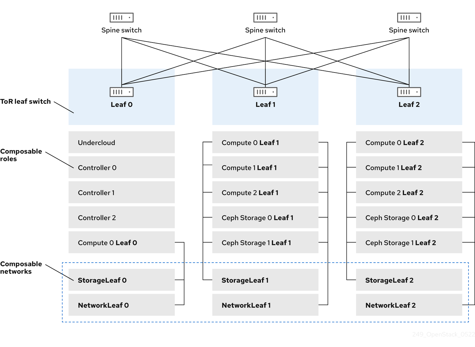
Red Hat OpenStack Platform has a composable network architecture that you can use to adapt your networking to the routed spine-leaf data center topology. In a practical application of routed spine-leaf, a leaf is represented as a composable Compute or Storage role usually in a data center rack, as shown in Figure 1.1, "Routed spine-leaf example". The Leaf 0 rack has an undercloud node, Controller nodes, and Compute nodes. The composable networks are presented to the nodes, which have been assigned to composable roles. The following diagram contains the following configuration:
-
The
StorageLeafnetworks are presented to the Ceph storage and Compute nodes. -
The
NetworkLeafrepresents an example of any network you might want to compose.
Figure 1.1. Routed spine-leaf example
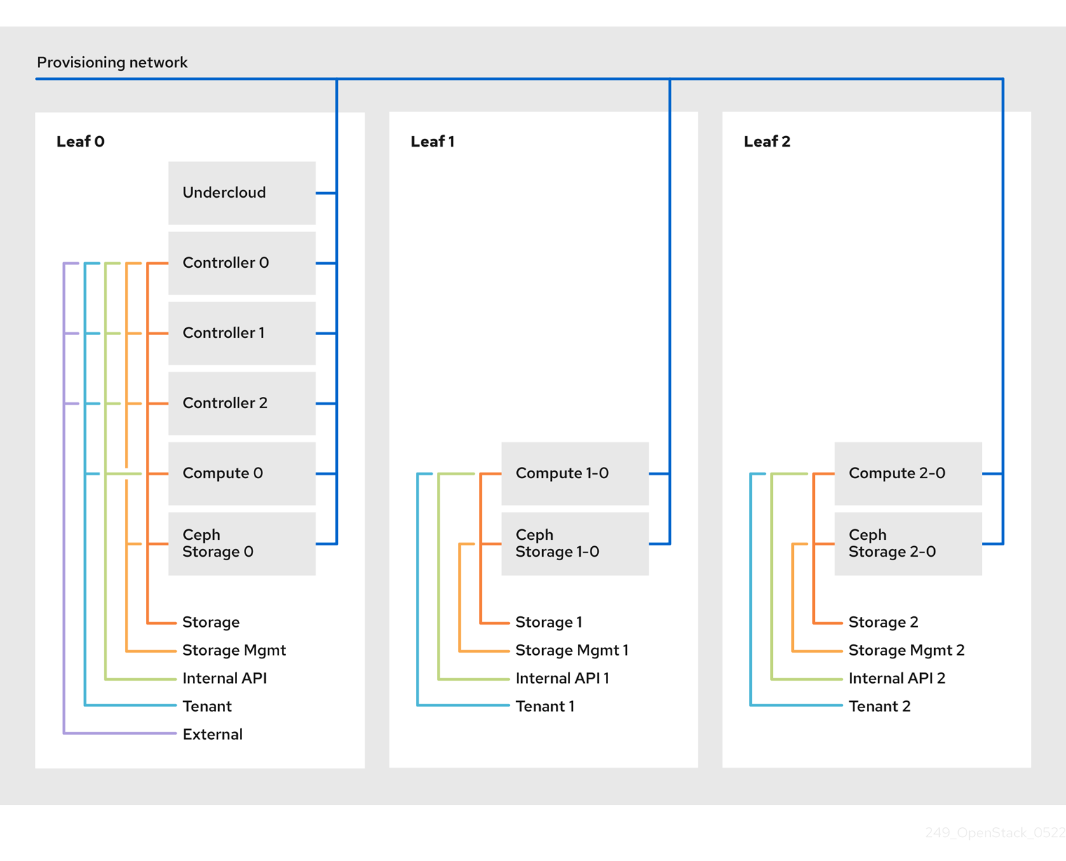
1.2. Spine-leaf network topology
The spine-leaf scenario takes advantage of OpenStack Networking (neutron) functionality to define multiple subnets within segments of a single network. Each network uses a base network which acts as Leaf 0. Director creates Leaf 1 and Leaf 2 subnets as segments of the main network.
This scenario uses the following networks:
| Network | Roles attached | Subnet |
|---|---|---|
| Provisioning / Ctlplane / Leaf0 | Controller, ComputeLeaf0, CephStorageLeaf0 | 192.168.10.0/24 |
| Storage | Controller, ComputeLeaf0, CephStorageLeaf0 | 172.16.0.0/24 |
| StorageMgmt | Controller, CephStorageLeaf0 | 172.17.0.0/24 |
| InternalApi | Controller, ComputeLeaf0 | 172.18.0.0/24 |
| Tenant [1] | Controller, ComputeLeaf0 | 172.19.0.0/24 |
| External | Controller | 10.1.1.0/24 |
[1] Tenant networks are also known as project networks.
| Network | Roles attached | Subnet |
|---|---|---|
| Provisioning / Ctlplane / Leaf1 | ComputeLeaf1, CephStorageLeaf1 | 192.168.11.0/24 |
| StorageLeaf1 | ComputeLeaf1, CephStorageLeaf1 | 172.16.1.0/24 |
| StorageMgmtLeaf1 | CephStorageLeaf1 | 172.17.1.0/24 |
| InternalApiLeaf1 | ComputeLeaf1 | 172.18.1.0/24 |
| TenantLeaf1 [1] | ComputeLeaf1 | 172.19.1.0/24 |
[1] Tenant networks are also known as project networks.
| Network | Roles attached | Subnet |
|---|---|---|
| Provisioning / Ctlplane / Leaf2 | ComputeLeaf2, CephStorageLeaf2 | 192.168.12.0/24 |
| StorageLeaf2 | ComputeLeaf2, CephStorageLeaf2 | 172.16.2.0/24 |
| StorageMgmtLeaf2 | CephStorageLeaf2 | 172.17.2.0/24 |
| InternalApiLeaf2 | ComputeLeaf2 | 172.18.2.0/24 |
| TenantLeaf2 [1] | ComputeLeaf2 | 172.19.2.0/24 |
[1] Tenant networks are also known as project networks.
Figure 1.2. Spine-leaf network topology
1.3. Spine-leaf requirements
To deploy the overcloud on a network with a L3 routed architecture, complete the following prerequisite steps:
- Layer-3 routing
- Configure the routing of the network infrastructure to enable traffic between the different L2 segments. You can configure this routing statically or dynamically.
- DHCP-Relay
-
Each L2 segment not local to the undercloud must provide
dhcp-relay. You must forward DHCP requests to the undercloud on the provisioning network segment where the undercloud is connected.
The undercloud uses two DHCP servers. One for baremetal node introspection, and another for deploying overcloud nodes. Ensure that you read DHCP relay configuration to understand the requirements when you configure dhcp-relay.
1.4. Spine-leaf limitations
- Some roles, such as the Controller role, use virtual IP addresses and clustering. The mechanism behind this functionality requires L2 network connectivity between these nodes. You must place these nodes within the same leaf.
- Similar restrictions apply to Networker nodes. The network service implements highly-available default paths in the network with Virtual Router Redundancy Protocol (VRRP). Because VRRP uses a virtual router IP address, you must connect master and backup nodes to the same L2 network segment.
- When you use tenant or provider networks with VLAN segmentation, you must share the particular VLANs between all Networker and Compute nodes.
It is possible to configure the network service with multiple sets of Networker nodes. Each set of Networker nodes share routes for their networks, and VRRP provides highly-available default paths within each set of Networker nodes. In this type of configuration, all Networker nodes that share networks must be on the same L2 network segment.
Chapter 2. Configuring routed spine-leaf in the undercloud
This section describes a use case about how to configure the undercloud to accommodate routed spine-leaf with composable networks.
2.1. Configuring the spine leaf provisioning networks
To configure the provisioning networks for your spine leaf infrastructure, edit the undercloud.conf file and set the relevant parameters included in the following procedure.
Procedure
-
Log in to the undercloud as the
stackuser. If you do not already have an
undercloud.conffile, copy the sample template file:cp /usr/share/python-tripleoclient/undercloud.conf.sample ~/undercloud.conf
[stack@director ~]$ cp /usr/share/python-tripleoclient/undercloud.conf.sample ~/undercloud.confCopy to Clipboard Copied! Toggle word wrap Toggle overflow -
Edit the
undercloud.conffile. Set the following values in the
[DEFAULT]section:Set
local_ipto the undercloud IP onleaf0:local_ip = 192.168.10.1/24
local_ip = 192.168.10.1/24Copy to Clipboard Copied! Toggle word wrap Toggle overflow Set
undercloud_public_hostto the externally facing IP address of the undercloud:undercloud_public_host = 10.1.1.1
undercloud_public_host = 10.1.1.1Copy to Clipboard Copied! Toggle word wrap Toggle overflow Set
undercloud_admin_hostto the administration IP address of the undercloud. This IP address is usually on leaf0:undercloud_admin_host = 192.168.10.2
undercloud_admin_host = 192.168.10.2Copy to Clipboard Copied! Toggle word wrap Toggle overflow Set
local_interfaceto the interface to bridge for the local network:local_interface = eth1
local_interface = eth1Copy to Clipboard Copied! Toggle word wrap Toggle overflow Set
enable_routed_networkstotrue:enable_routed_networks = true
enable_routed_networks = trueCopy to Clipboard Copied! Toggle word wrap Toggle overflow Define your list of subnets using the
subnetsparameter. Define one subnet for each L2 segment in the routed spine and leaf:subnets = leaf0,leaf1,leaf2
subnets = leaf0,leaf1,leaf2Copy to Clipboard Copied! Toggle word wrap Toggle overflow Specify the subnet associated with the physical L2 segment local to the undercloud using the
local_subnetparameter:local_subnet = leaf0
local_subnet = leaf0Copy to Clipboard Copied! Toggle word wrap Toggle overflow Set the value of
undercloud_nameservers.undercloud_nameservers = 10.11.5.19,10.11.5.20
undercloud_nameservers = 10.11.5.19,10.11.5.20Copy to Clipboard Copied! Toggle word wrap Toggle overflow TipYou can find the current IP addresses of the DNS servers that are used for the undercloud nameserver by looking in /etc/resolv.conf.
Create a new section for each subnet that you define in the
subnetsparameter:Copy to Clipboard Copied! Toggle word wrap Toggle overflow -
Save the
undercloud.conffile. Run the undercloud installation command:
openstack undercloud install
[stack@director ~]$ openstack undercloud installCopy to Clipboard Copied! Toggle word wrap Toggle overflow
This configuration creates three subnets on the provisioning network or control plane. The overcloud uses each network to provision systems within each respective leaf.
To ensure proper relay of DHCP requests to the undercloud, you might need to configure a DHCP relay.
2.2. Configuring a DHCP relay
You run the DHCP relay service on a switch, router, or server that is connected to the remote network segment you want to forward the requests from.
Do not run the DHCP relay service on the undercloud.
The undercloud uses two DHCP servers on the provisioning network:
- An introspection DHCP server.
- A provisioning DHCP server.
You must configure the DHCP relay to forward DHCP requests to both DHCP servers on the undercloud.
You can use UDP broadcast with devices that support it to relay DHCP requests to the L2 network segment where the undercloud provisioning network is connected. Alternatively, you can use UDP unicast, which relays DHCP requests to specific IP addresses.
Configuration of DHCP relay on specific device types is beyond the scope of this document. As a reference, this document provides a DHCP relay configuration example using the implementation in ISC DHCP software. For more information, see manual page dhcrelay(8).
DHCP option 79 is required for some relays, particularly relays that serve DHCPv6 addresses, and relays that do not pass on the originating MAC address. For more information, see RFC6939.
Broadcast DHCP relay
This method relays DHCP requests using UDP broadcast traffic onto the L2 network segment where the DHCP server or servers reside. All devices on the network segment receive the broadcast traffic. When using UDP broadcast, both DHCP servers on the undercloud receive the relayed DHCP request. Depending on the implementation, you can configure this by specifying either the interface or IP network address:
- Interface
- Specify an interface that is connected to the L2 network segment where the DHCP requests are relayed.
- IP network address
- Specify the network address of the IP network where the DHCP requests are relayed.
Unicast DHCP relay
This method relays DHCP requests using UDP unicast traffic to specific DHCP servers. When you use UDP unicast, you must configure the device that provides the DHCP relay to relay DHCP requests to both the IP address that is assigned to the interface used for introspection on the undercloud and the IP address of the network namespace that the OpenStack Networking (neutron) service creates to host the DHCP service for the ctlplane network.
The interface used for introspection is the one defined as inspection_interface in the undercloud.conf file. If you have not set this parameter, the default interface for the undercloud is br-ctlplane.
It is common to use the br-ctlplane interface for introspection. The IP address that you define as the local_ip in the undercloud.conf file is on the br-ctlplane interface.
The IP address allocated to the Neutron DHCP namespace is the first address available in the IP range that you configure for the local_subnet in the undercloud.conf file. The first address in the IP range is the one that you define as dhcp_start in the configuration. For example, 192.168.10.10 is the IP address if you use the following configuration:
The IP address for the DHCP namespace is automatically allocated. In most cases, this address is the first address in the IP range. To verify that this is the case, run the following commands on the undercloud:
Example dhcrelay configuration
In the following examples, the dhcrelay command in the dhcp package uses the following configuration:
-
Interfaces to relay incoming DHCP request:
eth1,eth2, andeth3. -
Interface the undercloud DHCP servers on the network segment are connected to:
eth0. -
The DHCP server used for introspection is listening on IP address:
192.168.10.1. -
The DHCP server used for provisioning is listening on IP address
192.168.10.10.
This results in the following dhcrelay command:
dhcrelayversion 4.2.x:sudo dhcrelay -d --no-pid 192.168.10.10 192.168.10.1 \ -i eth0 -i eth1 -i eth2 -i eth3
$ sudo dhcrelay -d --no-pid 192.168.10.10 192.168.10.1 \
  -i eth0 -i eth1 -i eth2 -i eth3
Copy to Clipboard Copied! Toggle word wrap Toggle overflow dhcrelayversion 4.3.x and later:sudo dhcrelay -d --no-pid 192.168.10.10 192.168.10.1 \ -iu eth0 -id eth1 -id eth2 -id eth3
$ sudo dhcrelay -d --no-pid 192.168.10.10 192.168.10.1 \
  -iu eth0 -id eth1 -id eth2 -id eth3
Copy to Clipboard Copied! Toggle word wrap Toggle overflow
Example Cisco IOS routing switch configuration
This example uses the following Cisco IOS configuration to perform the following tasks:
- Configure a VLAN to use for the provisioning network.
- Add the IP address of the leaf.
-
Forward UDP and BOOTP requests to the introspection DHCP server that listens on IP address:
192.168.10.1. -
Forward UDP and BOOTP requests to the provisioning DHCP server that listens on IP address
192.168.10.10.
interface vlan 2
ip address 192.168.24.254 255.255.255.0
ip helper-address 192.168.10.1
ip helper-address 192.168.10.10
!
interface vlan 2
ip address 192.168.24.254 255.255.255.0
ip helper-address 192.168.10.1
ip helper-address 192.168.10.10
!Now that you have configured the provisioning network, you can configure the remaining overcloud leaf networks.
2.3. Creating flavors and tagging nodes for leaf networks
Each role in each leaf network requires a flavor and role assignment so that you can tag nodes into their respective leaf. Complete the following steps to create and assign each flavor to a role.
Procedure
Source the
stackrcfile:source ~/stackrc
[stack@director ~]$ source ~/stackrcCopy to Clipboard Copied! Toggle word wrap Toggle overflow Create flavors for each custom role:
ROLES="control compute_leaf0 compute_leaf1 compute_leaf2 ceph-storage_leaf0 ceph-storage_leaf1 ceph-storage_leaf2"
for ROLE in $ROLES; do openstack flavor create --id auto --ram <ram_size_mb> --disk <disk_size_gb> --vcpus <no_vcpus> $ROLE ; done
for ROLE in $ROLES; do openstack flavor set --property "cpu_arch"="x86_64" --property "capabilities:boot_option"="local" --property resources:DISK_GB='0' --property resources:MEMORY_MB='0' --property resources:VCPU='0' $ROLE ; done
$ ROLES="control compute_leaf0 compute_leaf1 compute_leaf2 ceph-storage_leaf0 ceph-storage_leaf1 ceph-storage_leaf2"
$ for ROLE in $ROLES; do openstack flavor create --id auto --ram <ram_size_mb> --disk <disk_size_gb> --vcpus <no_vcpus> $ROLE ; done
$ for ROLE in $ROLES; do openstack flavor set --property "cpu_arch"="x86_64" --property "capabilities:boot_option"="local" --property resources:DISK_GB='0' --property resources:MEMORY_MB='0' --property resources:VCPU='0' $ROLE ; done
Copy to Clipboard Copied! Toggle word wrap Toggle overflow -
Replace
<ram_size_mb>with the RAM of the bare metal node, in MB. -
Replace
<disk_size_gb>with the size of the disk on the bare metal node, in GB. -
Replace
<no_vcpus>with the number of CPUs on the bare metal node.
-
Replace
Retrieve a list of your nodes to identify their UUIDs:
openstack baremetal node list
(undercloud)$ openstack baremetal node listCopy to Clipboard Copied! Toggle word wrap Toggle overflow Tag each bare metal node to its leaf network and role by using a custom resource class:
openstack baremetal node set \
 --resource-class baremetal.LEAF-ROLE <node>
(undercloud)$ openstack baremetal node set \
 --resource-class baremetal.LEAF-ROLE <node>
Copy to Clipboard Copied! Toggle word wrap Toggle overflow Replace
<node>with the ID of the bare metal node.For example, enter the following command to tag a node with UUID
58c3d07e-24f2-48a7-bbb6-6843f0e8ee13to the Compute role on Leaf2:openstack baremetal node set \ --resource-class baremetal.COMPUTE-LEAF2 58c3d07e-24f2-48a7-bbb6-6843f0e8ee13
(undercloud)$ openstack baremetal node set \
 --resource-class baremetal.COMPUTE-LEAF2 58c3d07e-24f2-48a7-bbb6-6843f0e8ee13
Copy to Clipboard Copied! Toggle word wrap Toggle overflow Associate each leaf network role flavor with the custom resource class:
openstack flavor set \
 --property resources:CUSTOM_BAREMETAL_LEAF_ROLE=1 \
<custom_role>
(undercloud)$ openstack flavor set \
 --property resources:CUSTOM_BAREMETAL_LEAF_ROLE=1 \
<custom_role>
Copy to Clipboard Copied! Toggle word wrap Toggle overflow To determine the name of a custom resource class that corresponds to a resource class of a Bare Metal Provisioning service node, convert the resource class to uppercase, replace each punctuation mark with an underscore, and prefix with
CUSTOM_.NoteA flavor can request only one instance of a bare metal resource class.
In the
node-info.yamlfile, specify the flavor that you want to use for each custom leaf role, and the number of nodes to allocate for each custom leaf role. For example, the following configuration specifies the flavor to use, and the number of nodes to allocate for the custom leaf rolescompute_leaf0,compute_leaf1,compute_leaf2,ceph-storage_leaf0,ceph-storage_leaf1, andceph-storage_leaf2:Copy to Clipboard Copied! Toggle word wrap Toggle overflow
2.4. Mapping bare metal node ports to control plane network segments
To enable deployment on a L3 routed network, you must configure the physical_network field on the bare metal ports. Each bare metal port is associated with a bare metal node in the OpenStack Bare Metal (ironic) service. The physical network names are the names that you include in the subnets option in the undercloud configuration.
The physical network name of the subnet specified as local_subnet in the undercloud.conf file is always named ctlplane.
Procedure
Source the
stackrcfile:source ~/stackrc
$ source ~/stackrcCopy to Clipboard Copied! Toggle word wrap Toggle overflow Check the bare metal nodes:
openstack baremetal node list
$ openstack baremetal node listCopy to Clipboard Copied! Toggle word wrap Toggle overflow Ensure that the bare metal nodes are either in
enrollormanageablestate. If the bare metal node is not in one of these states, the command that sets thephysical_networkproperty on the baremetal port fails. To set all nodes tomanageablestate, run the following command:for node in $(openstack baremetal node list -f value -c Name); do openstack baremetal node manage $node --wait; done
$ for node in $(openstack baremetal node list -f value -c Name); do openstack baremetal node manage $node --wait; doneCopy to Clipboard Copied! Toggle word wrap Toggle overflow Check which baremetal ports are associated with which baremetal node:
openstack baremetal port list --node <node-uuid>
$ openstack baremetal port list --node <node-uuid>Copy to Clipboard Copied! Toggle word wrap Toggle overflow Set the
physical-networkparameter for the ports. In the example below, three subnets are defined in the configuration:leaf0,leaf1, andleaf2. The local_subnet isleaf0. Because the physical network for thelocal_subnetis alwaysctlplane, the baremetal port connected toleaf0uses ctlplane. The remaining ports use the other leaf names:openstack baremetal port set --physical-network ctlplane <port-uuid> openstack baremetal port set --physical-network leaf1 <port-uuid> openstack baremetal port set --physical-network leaf2 <port-uuid>
$ openstack baremetal port set --physical-network ctlplane <port-uuid>
$ openstack baremetal port set --physical-network leaf1 <port-uuid>
$ openstack baremetal port set --physical-network leaf2 <port-uuid>
Copy to Clipboard Copied! Toggle word wrap Toggle overflow Introspect the nodes before you deploy the overcloud. Include the
--all-manageableand--provideoptions to set the nodes as available for deployment:openstack overcloud node introspect --all-manageable --provide
$ openstack overcloud node introspect --all-manageable --provideCopy to Clipboard Copied! Toggle word wrap Toggle overflow
2.5. Adding a new leaf to a spine-leaf provisioning network
When increasing network capacity which can include adding new physical sites, you might need to add a new leaf and a corresponding subnet to your Red Hat OpenStack Platform spine-leaf provisioning network. When provisioning a leaf on the overcloud, the corresponding undercloud leaf is used.
Prerequisites
- Your RHOSP deployment uses a spine-leaf network topology.
Procedure
- Log in to the undercloud host as the stack user.
Source the undercloud credentials file:
source ~/stackrc
$ source ~/stackrcCopy to Clipboard Copied! Toggle word wrap Toggle overflow In the
/home/stack/undercloud.conffile, do the following:Locate the
subnetsparameter, and add a new subnet for the leaf that you are adding.A subnet represents an L2 segment in the routed spine and leaf:
Example
In this example, a new subnet (
leaf3) is added for the new leaf (leaf3):subnets = leaf0,leaf1,leaf2,leaf3
subnets = leaf0,leaf1,leaf2,leaf3Copy to Clipboard Copied! Toggle word wrap Toggle overflow Create a section for the subnet that you added.
Example
In this example, the section
[leaf3]is added for the new subnet (leaf3):Copy to Clipboard Copied! Toggle word wrap Toggle overflow
-
Save the
undercloud.conffile. Reinstall your undercloud:
openstack undercloud install
$ openstack undercloud installCopy to Clipboard Copied! Toggle word wrap Toggle overflow
Chapter 3. Alternative provisioning network methods
This section contains information about other methods that you can use to configure the provisioning network to accommodate routed spine-leaf with composable networks.
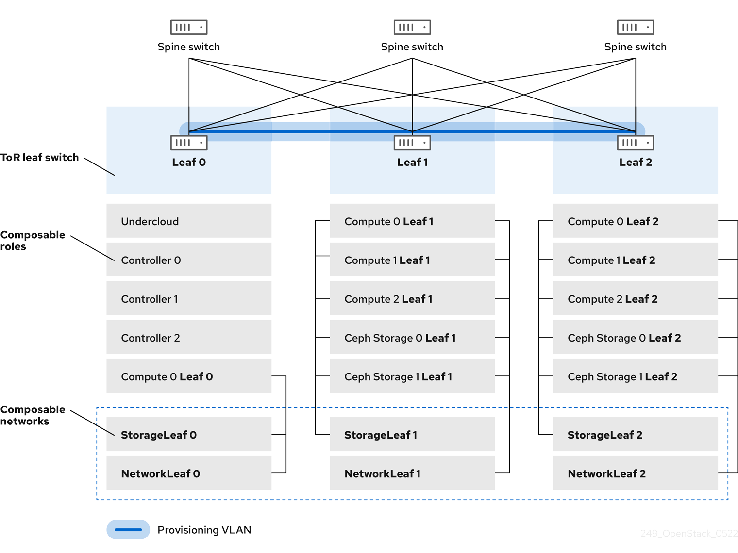
3.1. VLAN Provisioning network
In this example, the director deploys new overcloud nodes through the provisioning network and uses a VLAN tunnel across the L3 topology. For more information, see Figure 3.1, "VLAN provisioning network topology". If you use a VLAN provisioning network, the director DHCP servers can send DHCPOFFER broadcasts to any leaf. To establish this tunnel, trunk a VLAN between the Top-of-Rack (ToR) leaf switches. In the following diagram, the StorageLeaf networks are presented to the Ceph storage and Compute nodes; the NetworkLeaf represents an example of any network that you want to compose.
Figure 3.1. VLAN provisioning network topology
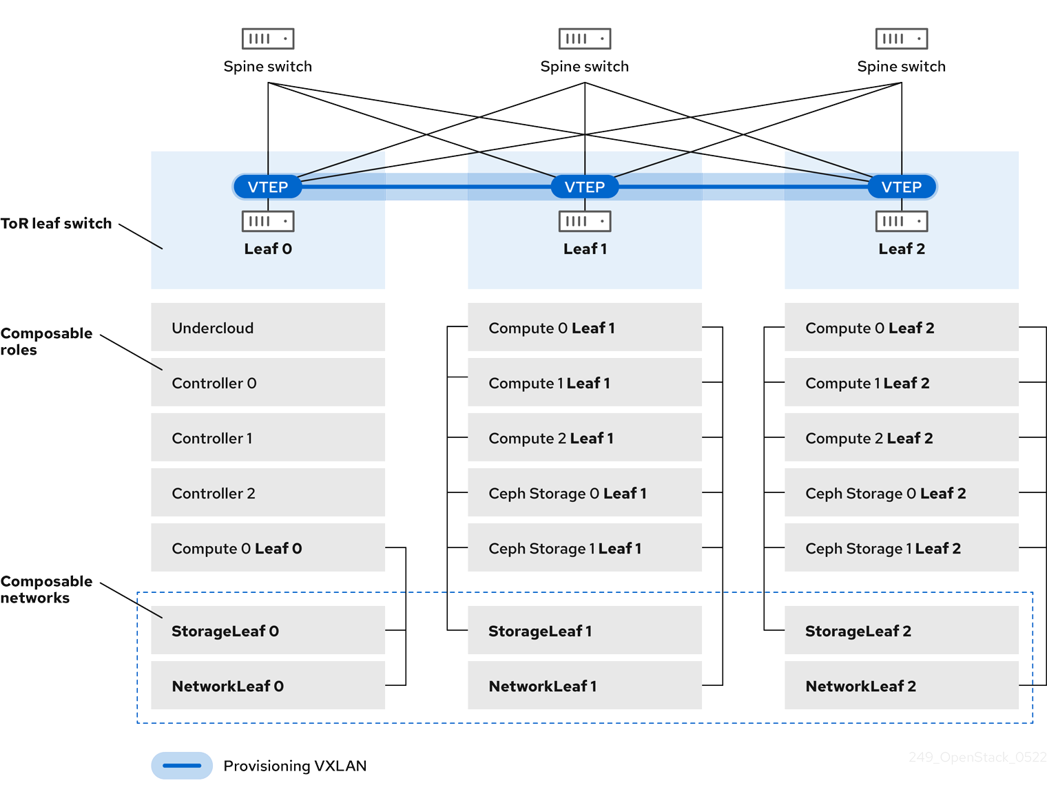
3.2. VXLAN Provisioning network
In this example, the director deploys new overcloud nodes through the provisioning network and uses a VXLAN tunnel to span across the layer 3 topology. For more information, see Figure 3.2, "VXLAN provisioning network topology". If you use a VXLAN provisioning network, the director DHCP servers can send DHCPOFFER broadcasts to any leaf. To establish this tunnel, configure VXLAN endpoints on the Top-of-Rack (ToR) leaf switches.
Figure 3.2. VXLAN provisioning network topology
Chapter 4. Configuring the overcloud
After you configure the undercloud, you can configure the remaining overcloud leaf networks with a series of configuration files. After you configure the remaining overcloud leaf networks and deploy the overcloud, the resulting deployment has multiple sets of networks with routing available.
4.1. Creating a network data file
To define the leaf networks, create a network data file that contains a YAML formatted list of each composable network and its attributes. Use the subnets parameter to define the additional Leaf subnets with a base network.
Procedure
Create a new
network_data_spine_leaf.yamlfile in the home directory of thestackuser. Use the defaultnetwork_data_subnets_routed.yamlfile as a basis:cp /usr/share/openstack-tripleo-heat-templates/network_data_subnets_routed.yaml /home/stack/network_data_spine_leaf.yaml
$ cp /usr/share/openstack-tripleo-heat-templates/network_data_subnets_routed.yaml /home/stack/network_data_spine_leaf.yamlCopy to Clipboard Copied! Toggle word wrap Toggle overflow In the
network_data_spine_leaf.yamlfile, edit the YAML list to define each base network and respective leaf subnets as a composable network item. Use the following example syntax to define a base leaf and two leaf subnets:Copy to Clipboard Copied! Toggle word wrap Toggle overflow The following example demonstrates how to define the Internal API network and its leaf networks:
Copy to Clipboard Copied! Toggle word wrap Toggle overflow
You do not define the Control Plane networks in the network data file because the undercloud has already created these networks. However, you must set the parameters manually so that the overcloud can configure the NICs accordingly.
Define vip: true for the networks that contain the Controller-based services. In this example, InternalApiLeaf0 contains these services.
4.2. Creating a roles data file
To define each composable role for each leaf and attach the composable networks to each respective role, complete the following steps.
Procedure
Create a custom
rolesdirectory in the home directory of thestackuser:mkdir ~/roles
$ mkdir ~/rolesCopy to Clipboard Copied! Toggle word wrap Toggle overflow Copy the default Controller, Compute, and Ceph Storage roles from the director core template collection to the roles directory. Rename the files for Compute and Ceph Storage to suit Leaf 0:
cp /usr/share/openstack-tripleo-heat-templates/roles/Controller.yaml ~/roles/Controller.yaml
cp /usr/share/openstack-tripleo-heat-templates/roles/Compute.yaml ~/roles/Compute0.yaml
cp /usr/share/openstack-tripleo-heat-templates/roles/CephStorage.yaml ~/roles/CephStorage0.yaml
$ cp /usr/share/openstack-tripleo-heat-templates/roles/Controller.yaml ~/roles/Controller.yaml
$ cp /usr/share/openstack-tripleo-heat-templates/roles/Compute.yaml ~/roles/Compute0.yaml
$ cp /usr/share/openstack-tripleo-heat-templates/roles/CephStorage.yaml ~/roles/CephStorage0.yaml
Copy to Clipboard Copied! Toggle word wrap Toggle overflow Copy the Leaf 0 Compute and Ceph Storage files as a basis for your Leaf 1 and Leaf 2 files:
cp ~/roles/Compute0.yaml ~/roles/Compute1.yaml
cp ~/roles/Compute0.yaml ~/roles/Compute2.yaml
cp ~/roles/CephStorage0.yaml ~/roles/CephStorage1.yaml
cp ~/roles/CephStorage0.yaml ~/roles/CephStorage2.yaml
$ cp ~/roles/Compute0.yaml ~/roles/Compute1.yaml
$ cp ~/roles/Compute0.yaml ~/roles/Compute2.yaml
$ cp ~/roles/CephStorage0.yaml ~/roles/CephStorage1.yaml
$ cp ~/roles/CephStorage0.yaml ~/roles/CephStorage2.yaml
Copy to Clipboard Copied! Toggle word wrap Toggle overflow Edit the
name,HostnameFormatDefault, anddeprecated_nic_config_nameparameters in the Leaf 0, Leaf 1, and Leaf 2 files so that they align with the respective Leaf parameters. For example, the parameters in the Leaf 0 Compute file have the following values:- name: ComputeLeaf0 HostnameFormatDefault: '%stackname%-compute-leaf0-%index%' deprecated_nic_config_name: 'computeleaf0.yaml'
- name: ComputeLeaf0 HostnameFormatDefault: '%stackname%-compute-leaf0-%index%' deprecated_nic_config_name: 'computeleaf0.yaml'Copy to Clipboard Copied! Toggle word wrap Toggle overflow The Leaf 0 Ceph Storage parameters have the following values:
- name: CephStorageLeaf0
  HostnameFormatDefault: '%stackname%-cephstorage-leaf0-%index%'
  deprecated_nic_config_name: 'ceph-strorageleaf0.yaml'
- name: CephStorageLeaf0
  HostnameFormatDefault: '%stackname%-cephstorage-leaf0-%index%'
  deprecated_nic_config_name: 'ceph-strorageleaf0.yaml'
Copy to Clipboard Copied! Toggle word wrap Toggle overflow Edit the
networkparameter in the Leaf 1 and Leaf 2 files so that they align with the respective Leaf network parameters. For example, the parameters in the Leaf 1 Compute file have the following values:Copy to Clipboard Copied! Toggle word wrap Toggle overflow The Leaf 1 Ceph Storage parameters have the following values:
Copy to Clipboard Copied! Toggle word wrap Toggle overflow NoteThis applies only to Leaf 1 and Leaf 2. The
networkparameter for Leaf 0 retains the base subnet values, which are the lowercase names of each subnet combined with a_subnetsuffix. For example, the Internal API for Leaf 0 isinternal_api_subnet.When your role configuration is complete, run the following command to generate the full roles data file:
openstack overcloud roles generate --roles-path ~/roles -o roles_data_spine_leaf.yaml Controller Compute Compute1 Compute2 CephStorage CephStorage1 CephStorage2
$ openstack overcloud roles generate --roles-path ~/roles -o roles_data_spine_leaf.yaml Controller Compute Compute1 Compute2 CephStorage CephStorage1 CephStorage2Copy to Clipboard Copied! Toggle word wrap Toggle overflow This creates a full
roles_data_spine_leaf.yamlfile that includes all of the custom roles for each respective leaf network.
Each role has its own NIC configuration. Before you configure the spine-leaf configuration, you must create a base set of NIC templates to suit your current NIC configuration.
4.3. Creating a custom NIC configuration
Each role requires a unique NIC configuration. Complete the following steps to create a copy of the base set of NIC templates and map the new templates to the respective NIC configuration resources.
Procedure
Change to the core heat template directory:
cd /usr/share/openstack-tripleo-heat-templates
$ cd /usr/share/openstack-tripleo-heat-templatesCopy to Clipboard Copied! Toggle word wrap Toggle overflow Render the Jinja2 templates with the
tools/process-templates.pyscript, your customnetwork_datafile, and customroles_datafile:tools/process-templates.py \ -n /home/stack/network_data_spine_leaf.yaml \ -r /home/stack/roles_data_spine_leaf.yaml \ -o /home/stack/openstack-tripleo-heat-templates-spine-leaf$ tools/process-templates.py \ -n /home/stack/network_data_spine_leaf.yaml \ -r /home/stack/roles_data_spine_leaf.yaml \ -o /home/stack/openstack-tripleo-heat-templates-spine-leafCopy to Clipboard Copied! Toggle word wrap Toggle overflow Change to the home directory:
cd /home/stack
$ cd /home/stackCopy to Clipboard Copied! Toggle word wrap Toggle overflow Copy the content from one of the default NIC templates to use as a basis for your spine-leaf templates. For example, copy the
single-nic-vlansNIC template:cp -r openstack-tripleo-heat-templates-spine-leaf/network/config/single-nic-vlans/* /home/stack/templates/spine-leaf-nics/.
$ cp -r openstack-tripleo-heat-templates-spine-leaf/network/config/single-nic-vlans/* /home/stack/templates/spine-leaf-nics/.Copy to Clipboard Copied! Toggle word wrap Toggle overflow Edit each NIC configuration in
/home/stack/templates/spine-leaf-nics/and change the location of the configuration script to an absolute location. Scroll to the network configuration section, which resembles the following snippet:Copy to Clipboard Copied! Toggle word wrap Toggle overflow Change the location of the script to the absolute path:
Copy to Clipboard Copied! Toggle word wrap Toggle overflow Make this change in each file for each Leaf and save the changes.
NoteFor further NIC changes, see Custom network interface templates in the Advanced Overcloud Customization guide.
-
Create a file called
spine-leaf-nics.yamland edit the file. Create a
resource_registrysection in the file and add a set of::Net::SoftwareConfigresources that map to the respective NIC templates:Copy to Clipboard Copied! Toggle word wrap Toggle overflow These resources mappings override the default resource mappings during deployment.
-
Save the
spine-leaf-nics.yamlfile. Remove the rendered template directory:
rm -rf openstack-tripleo-heat-templates-spine-leaf
$ rm -rf openstack-tripleo-heat-templates-spine-leafCopy to Clipboard Copied! Toggle word wrap Toggle overflow As a result of this procedure, you now have a set of NIC templates and an environment file that maps the required
::Net::SoftwareConfigresources to them.When you eventually run the
openstack overcloud deploycommand, ensure that you include the environment files in the following order:-
/usr/share/openstack-tripleo-heat-templates/environments/network-isolation.yaml, which enables network isolation. Note that the director renders this file from thenetwork-isolation.j2.yamlJinja2 template. -
/usr/share/openstack-tripleo-heat-templates/environments/network-environment.yaml, which is the default network environment file, including default NIC resource mappings. Note that the director renders this file from thenetwork-environment.j2.yamlJinja2 template. /home/stack/templates/spine-leaf-nics.yaml, which contains your custom NIC resource mappings and overrides the default NIC resource mappings.The following command snippet demonstrates the ordering:
Copy to Clipboard Copied! Toggle word wrap Toggle overflow
-
-
Complete the procedures in the following sections to add details to your network environment file, and define certain aspects of the spine leaf architecture. After you complete this configuration, include this file in the
openstack overcloud deploycommand.
4.4. Setting control plane parameters
You usually define networking details for isolated spine-leaf networks using a network_data file. The exception is the control plane network, which the undercloud creates. However, the overcloud requires access to the control plane for each leaf. To enable this access, you must define additional parameters in your deployment.
In this example, define the IP, subnet, and default route for the respective Control Plane network on Leaf 0.
Procedure
-
Create a file called
spine-leaf-ctlplane.yamland edit the file. Create a
parameter_defaultssection in the file and add the control plane subnet mapping for each spine-leaf network:Copy to Clipboard Copied! Toggle word wrap Toggle overflow -
Save the
spine-leaf-ctlplane.yamlfile.
4.5. Setting the subnet for virtual IP addresses
The Controller role typically hosts virtual IP (VIP) addresses for each network. By default, the overcloud takes the VIPs from the base subnet of each network except for the control plane. The control plane uses ctlplane-subnet, which is the default subnet name created during a standard undercloud installation.
In this spine leaf scenario, the default base provisioning network is leaf0 instead of ctlplane-subnet. This means that you must add overriding values to the VipSubnetMap parameter to change the subnet that the control plane VIP uses.
Additionally, if the VIPs for each network do not use the base subnet of one or more networks, you must add additional overrides to the VipSubnetMap parameter to ensure that the director creates VIPs on the subnet associated with the L2 network segment that connects the Controller nodes.
Procedure:
-
Create a file called
spine-leaf-vips.yamland edit the file. Create a
parameter_defaultssection in the file and add theVipSubnetMapparameter based on your requirements:If you use
leaf0for the provisioning / control plane network, set thectlplaneVIP remapping toleaf0:parameter_defaults: VipSubnetMap: ctlplane: leaf0parameter_defaults: VipSubnetMap: ctlplane: leaf0Copy to Clipboard Copied! Toggle word wrap Toggle overflow If you use a different Leaf for multiple VIPs, set the VIP remapping to suit these requirements. For example, use the following snippet to configure the
VipSubnetMapparameter to useleaf1for all VIPs:Copy to Clipboard Copied! Toggle word wrap Toggle overflow
-
Save the
spine-leaf-vips.yamlfile.
4.6. Mapping separate networks
By default, OpenStack Platform uses Open Virtual Network (OVN), which requires that all Controller and Compute nodes connect to a single L2 network for external network access. This means that both Controller and Compute network configurations use a br-ex bridge, which director maps to the datacentre network in the overcloud by default. This mapping is usually either for a flat network mapping or a VLAN network mapping. In a spine leaf architecture, you can change these mappings so that each Leaf routes traffic through the specific bridge or VLAN on that Leaf, which is often the case with edge computing scenarios.
Procedure
-
Create a file called
spine-leaf-separate.yamland edit the file. Create a
parameter_defaultssection in thespine-leaf-separate.yamlfile and include the external network mapping for each spine-leaf network:For flat network mappings, list each Leaf in the
NeutronFlatNetworksparameter and set theNeutronBridgeMappingsparameter for each Leaf:Copy to Clipboard Copied! Toggle word wrap Toggle overflow For VLAN network mappings, additionally set the
NeutronNetworkVLANRangesto map VLANs for all three Leaf networks:NeutronNetworkType: 'geneve,vlan' NeutronNetworkVLANRanges: 'leaf0:1:1000,leaf1:1:1000,leaf2:1:1000'
NeutronNetworkType: 'geneve,vlan' NeutronNetworkVLANRanges: 'leaf0:1:1000,leaf1:1:1000,leaf2:1:1000'Copy to Clipboard Copied! Toggle word wrap Toggle overflow
-
Save the
spine-leaf-separate.yamlfile.
4.7. Deploying a spine-leaf enabled overcloud
When you have completed your spine-leaf overcloud configuration, complete the following steps to review each file and then run the deployment command:
Procedure
Review the
/home/stack/template/network_data_spine_leaf.yamlfile and ensure that it contains each network and subnet for each leaf.NoteThere is currently no automatic validation for the network subnet and
allocation_poolsvalues. Ensure that you define these values consistently and that there is no conflict with existing networks.-
Review the
/home/stack/templates/roles_data_spine_leaf.yamlvalues and ensure that you define a role for each leaf. -
Review the NIC templates in the
~/templates/spine-leaf-nics/directory and ensure that you define the interfaces for each role on each leaf correctly. -
Review the custom
spine-leaf-nics.yamlenvironment file and ensure that it contains aresource_registrysection that references the custom NIC templates for each role. -
Review the
/home/stack/templates/nodes_data.yamlfile and ensure that all roles have an assigned flavor and a node count. Also check that you have correctly tagged all nodes for each leaf. Run the
openstack overcloud deploycommand to apply the spine leaf configuration. For example:Copy to Clipboard Copied! Toggle word wrap Toggle overflow -
The
network-isolation.yamlis the rendered name of the Jinja2 file in the same location (network-isolation.j2.yaml). Include this file in the deployment command to ensure that the director isolates each networks to the correct leaf. This ensures that the networks are created dynamically during the overcloud creation process. -
Include the
network-environment.yamlfile after thenetwork-isolation.yaml. Thenetwork-environment.yamlfile provides the default network configuration for composable network parameters. -
Include the
spine-leaf-nics.yamlfile after thenetwork-environment.yaml. Thespine-leaf-nics.yamlfile overrides the default NIC template mappings from thenetwork-environment.yamlfile. -
If you created any other spine leaf network environment files, include these environment files after the
spine-leaf-nics.yamlfile. - Add any additional environment files. For example, an environment file with your container image locations or Ceph cluster configuration.
-
The
- Wait until the spine-leaf enabled overcloud deploys.
4.8. Adding a new leaf to a spine-leaf deployment
When increasing network capacity or adding a new physical site, you might need to a new leaf to your Red Hat OpenStack Platform (RHOSP) spine-leaf network.
Prerequisites
- Your RHOSP deployment uses a spine-leaf network topology.
Procedure
- Log in to the undercloud host as the stack user.
Source the undercloud credentials file:
source ~/stackrc
$ source ~/stackrcCopy to Clipboard Copied! Toggle word wrap Toggle overflow In the
/usr/share/openstack-tripleo-heat-templates/network_data_spine_leaf.yamlfile, under the appropriate base network, add a leaf subnet as a composable network item for the new leaf that you are adding.Example
In this example, a subnet entry for the new leaf (
leaf3) has been added:Copy to Clipboard Copied! Toggle word wrap Toggle overflow Create a roles data file for the new leaf that you are adding.
Copy a leaf Compute and a leaf Ceph Storage file for the new leaf that you are adding.
Example
In this example,
Compute1.yamlandCephStorage1.yamlare copied for the new leaf,Compute3.yamlandCephStorage3.yaml, repectively:cp ~/roles/Compute1.yaml ~/roles/Compute3.yaml cp ~/roles/CephStorage1.yaml ~/roles/CephStorage3.yaml
$ cp ~/roles/Compute1.yaml ~/roles/Compute3.yaml
$ cp ~/roles/CephStorage1.yaml ~/roles/CephStorage3.yaml
Copy to Clipboard Copied! Toggle word wrap Toggle overflow Edit the
name,HostnameFormatDefault, anddeprecated_nic_config_nameparameters in the new leaf files so that they align with the respective Leaf parameters.Example
For example, the parameters in the Leaf 1 Compute file have the following values:
- name: ComputeLeaf1
  HostnameFormatDefault: '%stackname%-compute-leaf1-%index%'
  deprecated_nic_config_name: 'computeleaf1.yaml'
- name: ComputeLeaf1
  HostnameFormatDefault: '%stackname%-compute-leaf1-%index%'
  deprecated_nic_config_name: 'computeleaf1.yaml'
Copy to Clipboard Copied! Toggle word wrap Toggle overflow Example
The Leaf 1 Ceph Storage parameters have the following values:
- name: CephStorageLeaf1
  HostnameFormatDefault: '%stackname%-cephstorage-leaf1-%index%'
  deprecated_nic_config_name: 'ceph-strorageleaf1.yaml'
- name: CephStorageLeaf1
  HostnameFormatDefault: '%stackname%-cephstorage-leaf1-%index%'
  deprecated_nic_config_name: 'ceph-strorageleaf1.yaml'
Copy to Clipboard Copied! Toggle word wrap Toggle overflow Edit the network parameter in the new leaf files so that they align with the respective Leaf network parameters.
Example
For example, the parameters in the Leaf 1 Compute file have the following values:
Copy to Clipboard Copied! Toggle word wrap Toggle overflow Example
The Leaf 1 Ceph Storage parameters have the following values:
Copy to Clipboard Copied! Toggle word wrap Toggle overflow When your role configuration is complete, run the following command to generate the full roles data file. Include all of the leafs in your network and the new leaf that you are adding.
Example
In this example, leaf3 is added to leaf0, leaf1, and leaf2:
openstack overcloud roles generate --roles-path ~/roles -o roles_data_spine_leaf.yaml Controller Compute Compute1 Compute2 Compute3 CephStorage CephStorage1 CephStorage2 CephStorage3
$ openstack overcloud roles generate --roles-path ~/roles -o roles_data_spine_leaf.yaml Controller Compute Compute1 Compute2 Compute3 CephStorage CephStorage1 CephStorage2 CephStorage3Copy to Clipboard Copied! Toggle word wrap Toggle overflow This creates a full
roles_data_spine_leaf.yamlfile that includes all of the custom roles for each respective leaf network.
Create a custom NIC configuration for the leaf that you are adding.
Copy a leaf Compute and a leaf Ceph Storage NIC configuration file for the new leaf that you are adding.
Example
In this example,
computeleaf1.yamlandceph-storageleaf1.yamlare copied for the new leaf,computeleaf3.yamlandceph-storageleaf3.yaml, repectively:cp ~/templates/spine-leaf-nics/computeleaf1.yaml ~/templates/spine-leaf-nics/computeleaf3.yaml cp ~/templates/spine-leaf-nics/ceph-storageleaf1.yaml ~/templates/spine-leaf-nics/ceph-storageleaf3.yaml
$ cp ~/templates/spine-leaf-nics/computeleaf1.yaml ~/templates/spine-leaf-nics/computeleaf3.yaml
$ cp ~/templates/spine-leaf-nics/ceph-storageleaf1.yaml ~/templates/spine-leaf-nics/ceph-storageleaf3.yaml
Copy to Clipboard Copied! Toggle word wrap Toggle overflow In
/usr/share/openstack-tripleo-heat-templates/network_data_spine_leaf.yaml, under theresource_registrysection in the file, add a set of::Net::SoftwareConfigresources that map to the respective NIC templates:Example
In this example, the new leaf NIC configuration files (
computeleaf3.yamlandceph-storageleaf3.yaml) have been added:Copy to Clipboard Copied! Toggle word wrap Toggle overflow These resources mappings override the default resource mappings during deployment.
As a result of this procedure, you now have a set of NIC templates and an environment file that maps the required
::Net::SoftwareConfigresources to them. When you eventually run theopenstack overcloud deploycommand, ensure that you include the environment files in the following order:/usr/share/openstack-tripleo-heat-templates/environments/network-isolation.yaml, which enables network isolation.Note that the director renders this file from the
network-isolation.j2.yamlJinja2 template./usr/share/openstack-tripleo-heat-templates/environments/network-environment.yaml, which is the default network environment file, including default NIC resource mappings.Note that the director renders this file from the network-environment.j2.yaml Jinja2 template.
/home/stack/templates/spine-leaf-nics.yaml, which contains your custom NIC resource mappings and overrides the default NIC resource mappings.The following command snippet demonstrates the ordering:
Copy to Clipboard Copied! Toggle word wrap Toggle overflow
Update the control plane parameters.
In
~/templates/spine-leaf-ctlplane.yaml, under theparameter_defaultssection, add the control plane subnet mapping for the new leaf network:Example
In this example, the new leaf (
leaf3) entries are added:Copy to Clipboard Copied! Toggle word wrap Toggle overflow Map the new leaf network.
In
~/templates/spine-leaf-separate.yaml, under theparameter_defaultssection, include the external network mapping for the new leaf network.For flat network mappings, list the new leaf (
leaf3) in theNeutronFlatNetworksparameter and set theNeutronBridgeMappingsparameter for the new leaf:Copy to Clipboard Copied! Toggle word wrap Toggle overflow For VLAN network mappings, additionally set the
NeutronNetworkVLANRangesto map VLANs for the new leaf (leaf3) network:NeutronNetworkType: 'geneve,vlan' NeutronNetworkVLANRanges: 'leaf0:1:1000,leaf1:1:1000,leaf2:1:1000,leaf3:1:1000'
NeutronNetworkType: 'geneve,vlan' NeutronNetworkVLANRanges: 'leaf0:1:1000,leaf1:1:1000,leaf2:1:1000,leaf3:1:1000'Copy to Clipboard Copied! Toggle word wrap Toggle overflow
- Redeploy your spine-leaf enabled overcloud, by following the steps in Section 4.7, “Deploying a spine-leaf enabled overcloud”.