Chapter 6. Process Modeling
6.1. Some Helpful Definitions
Read this section to learn the terminology that you will find used throughout the rest of this book.
A process definition represents a formal specification of a business process and is based on a directed graph. The graph is composed of nodes and transitions. Every node in the graph is of a specific type. The node type defines the run-time behavior. A process definition only has one start state.
A token is one path of execution. A token is the runtime concept that maintains a pointer to a node in the graph.
A process instance is one execution of a process definition. When a process instance is created, a token is generated for the main path of execution. This token is called the root token of the process instance and it is positioned in the start state of the process definition.
A signal instructs a token to continue to execute the graph. When it receives an unnamed signal, the token will leave its current node over the default leaving transition. When a transition-name is specified in the signal, the token will leave its node over the specified transition. A signal given to the process instance is delegated to the root token.
After the token has entered a node, the node is executed. Nodes themselves are responsible for making the graph execution continue. Continuation of graph execution is achieved by making the token leave the node. Each type of node can implement a different behavior for the continuation of the graph execution. A node that does not pass on the execution will behave as a state.
Actions are pieces of Java code that are executed upon events during the process execution. The graph is an important instrument in the communication of software requirements but it is just one view (projection) of the software being produced. It hides many technical details. Actions are a mechanism used to add technical details beyond those of the graphical representation. Once the graph is put in place, it can be decorated with actions. The main event types are
entering a node, leaving a node and taking a transition.
Having learned these definitions, read on to find out how process modelling works.
6.2. Process Graph
A process definition is a graph that is made up of nodes and transitions. This information is expressed in XML and found in a file called
processdefinition.xml. Each node must have a type (examples being state, decision, fork and join.) Each node has a set of leaving transitions. Names can be given to the transitions that leave a node in order to make them distinct from each other. For example, the following diagram shows a process graph for an auction process.
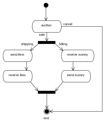
Figure 6.1. The auction process graph
Below is the process graph for the same auction process represented in XML:
<process-definition>

  <start-state>
    <transition to="auction" />
  </start-state>

  <state name="auction">
    <transition name="auction ends" to="salefork" />
    <transition name="cancel" to="end" />
  </state>

  <fork name="salefork">
    <transition name="shipping" to="send item" />
    <transition name="billing" to="receive money" />
  </fork>

  <state name="send item">
    <transition to="receive item" />
  </state>

  <state name="receive item">
    <transition to="salejoin" />
  </state>

  <state name="receive money">
    <transition to="send money" />
  </state>

  <state name="send money">
    <transition to="salejoin" />
  </state>

  <join name="salejoin">
    <transition to="end" />
  </join>

  <end-state name="end" />

</process-definition>
6.3. Nodes
A process graph is made up of nodes and transitions. Each node is of a specific type. The node type determines what will happen when an execution arrives in the node at run-time. The Business Process Manager provides a set of node types to use. Alternatively, you can write custom codes to implement a specific node behavior.
6.3.1. Node Responsibilities
Each node has two main responsibilities: firstly, it can execute plain Java code, code which will normally relate to the function of the node. Its second responsibility is to pass on the process execution.
A node may face the following options when it attempts to pass the process execution on. It will follow that course which is most applicable:
- it can not propagate the execution. (The node behaves as a
wait state.) - it can propagate the execution over one of the node's
leaving transitions. (This means that the token that originally arrived in the node is passed over one of theleaving transitionswith the API callexecutionContext.leaveNode(String).) The node will now act automatically in the sense that it will execute some custom programming logic and then continue the process execution automatically without waiting. - a node can "decide" to create new tokens, each of which will represent a new path of execution. Each of these new tokens can be launched over the node's
leaving transitions. A good example of this kind of behavior is thefork node. - it can end the path of execution. This means that the token has concluded.
- it can modify the whole run-time structure of the process instance. The run-time structure is a process instance that contains a tree of tokens, each of which represents a path of execution. A node can create and end tokens, put each token in a node of the graph and launch tokens over transitions.
The Business Process Manager contains a set of pre-implemented node types, each of which has a specific configuration and behavior. However, you can also write your own node behavior and use it in a process.
6.3.2. Node Type: Task Node
A task node represents one or more tasks that are to be performed manually. Thus, when the execution process arrives in a node, task instances will be created in the lists belonging to the workflow participants. After that, the node will enter a
wait state. When the users complete their tasks, the execution will be triggered, making it resume.
6.3.3. Node Type: State
A state is a "bare bones"
wait state. It differs from a task node in that no task instances will be created for any task list. This can be useful if the process is waiting for an external system. After that, the process will go into a wait state. When the external system send a response message, a token.signal() is normally invoked, triggering the resumption of the process execution.
6.3.4. Node Type: Decision
There are two ways in which one can model a decision, the choice as to which to use being left to the discretion of the user. The options are:
- the decision is made by the process, and is therefore specified in the process definition,
- an external entity decides.
When the decision is to be undertaken by the process, use a
decision node. Specify the decision criteria in one of two ways, the simplest being to add condition elements to the transitions. (Conditions are EL expressions or beanshell scripts that return a Boolean value.)
At run-time, the decision node will loop over those
leaving transitions which have conditions have been specified. It will evaluate those transitions first in the order specified in the XML. The first transition for which the condition resolves to true will be taken. If the conditions for all transitions resolve to false, the default transition, (the first in the XML), will taken instead. If no default transition is found, a JbpmException is thrown.
The second approach is to use an expression that returns the name of the transition to take. Use the expression attribute to specify an expression on the decision. This will need to resolve to one of the decision node's
leaving transitions.
One can also use the handler element on the decision, as this element can be used to specify an implementation of the
DecisionHandler interface that can be specified on the decision node. In this scenario, the decision is calculated by a Java class and the selected leaving transition is returned by the decide method, which belongs to the DecisionHandler implementation.
When the decision is undertaken by an external party, always use multiple transitions that will leave a
state or wait state node. The leaving transition can then be provided in the external trigger that resumes execution after the wait state is finished (these might, for example, be Token.signal(String transitionName) or TaskInstance.end(String transitionName).)
6.3.5. Node Type: Fork
A fork splits a single path of execution into multiple concurrent ones. By default, the fork creates a child token for each transition that leaves it, (thereby creating a parent-child relation between the tokens that arrives in the fork.)
6.3.6. Node Type: Join
By default, the join assumes that all tokens that arrive within itself are children of the same parent. (This situation occurs when using the fork as mentioned above and when all tokens created by a fork arrive in the same join.)
A join will end every token that enters it. It will then examine the parent-child relation of those tokens. When all sibling tokens have arrived in the join, the parent token will be passed through to the
leaving transition. When there are still sibling tokens active, the join will behave as a wait state.
6.3.7. Node Type: Node
Use this node to avoid writing custom code. It expects only one sub-element action, which will be run when the execution arrives in the node. Custom code written in
actionhandler can do anything but be aware that it is also responsible for passing on the execution. (See Section 6.3.1, “ Node Responsibilities ” for more information.)
This node can also be used when one is utilizing a Java API to implement some functional logic for a corporate business analyst. It is advantageous to do so this way because the node remains visible in the graphical representation of the process. (Use actions to add code that is invisible in the graphical representation of the process.)
6.4. Transitions
Transitions have both source and destination nodes. The source node is represented by the property from and the destination is represented by to.
A transition can, optionally, be given a name. (Most features of the Business Process Manager depend on transitions being given unique names.) If more than one transition has the same name, the first of these will be taken. (In case duplicate transition names occur in a node, the
Map getLeavingTransitionsMap() method will return less elements than List getLeavingTransitions().)
6.5. Actions
Actions are pieces of java code that are executed upon events in the process execution. The graph is an important instrument in the communication about software requirements. But the graph is just one view (projection) of the software being produced. It hides many technical details. Actions are a mechanism to add technical details outside of the graphical representation. Once the graph is put in place, it can be decorated with actions. This means that java code can be associated with the graph without changing the structure of the graph. The main event types are entering a node, leaving a node and taking a transition.
Important
There is a difference between an action that is placed on an event and an action that is placed in a node. Actions that are put in events are executed when the event fires. They have no way to influence the flow of control of the process. (It is similar to the observer pattern.) By contrast, an action placed on a node has the responsibility of passing on the execution.
Read this section to study an example of an action on an event. It demonstrates how to undertake a database update on a given transition. (The database update is technically vital but it is not of importance to the business analyst.)
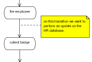
Figure 6.2. A database update action
public class RemoveEmployeeUpdate implements ActionHandler {
  public void execute(ExecutionContext ctx) throws Exception {
    // get the fired employee from the process variables.
    String firedEmployee =
      (String) ctx.getContextInstance().getVariable("fired employee");

    // by taking the same database connection as used for the jbpm
    // updates, we reuse the jbpm transaction for our database update.
    Connection connection =
    ctx.getProcessInstance().getJbpmSession().getSession().getConnection();
    Statement statement = connection.createStatement();
    statement.execute("DELETE FROM EMPLOYEE WHERE ...");
    statement.execute();
    statement.close();
  }
}
<process-definition name="yearly evaluation">
<state name="fire employee">
<transition to="collect badge">
<action class="com.nomercy.hr.RemoveEmployeeUpdate" />
</transition>
</state>
<state name="collect badge">
</process-definition>6.5.1. Action References
Actions can be given names. This allows for them be referenced from other locations in which actions are specified. Named actions can also be added to the process definition as child elements.
Use this feature to limit duplication of action configurations. (This is particularly helpful when the action has complicated configurations or when run-time actions have to be scheduled or executed.)
6.5.2. Events
Events are specific moments in the execution of the process. The Business Process Manager's engine will "fire" events during graph execution, which occurs when the software calculates the next state, (in other words, when it processes a signal.) An event is always relative to an element in the process definition.
Most process elements can fire different types of events. A node, for example, can fire both
node-enter and node-leave events. (Events are the "hooks" for actions. Each event has a list of actions. When the jBPM engine fires an event, the list of actions is executed.)
6.5.3. Passing On Events
A super-state creates a parent-child relation in the elements of a process definition. (Nodes and transitions contained in a super-state will have that superstate as a parent. Top-level elements have the process definition as their parent which, itself, does not have a further parent.) When an event is fired, the event will be passed up the parent hierarchy. This allows it both to capture all transition events in a process and to associate actions with these events via a centralized location.
6.5.4. Scripts
A script is an action that executes a Beanshell script. (For more information about Beanshell, see http://www.beanshell.org/.) By default, all process variables are available as script variables but no script variables will be written to the process variables. The following script-variables are available:
- executionContext
- token
- node
- task
- taskInstance
<process-definition>
  <event type="node-enter">
    <script>
      System.out.println("this script is entering node "+node);
    </script>
  </event>
  ...
</process-definition>
To customize the default behavior of loading and storing variables into the script, use the variable element as a sub-element of script. If doing so, also place the script expression into the script as a sub-element: expression.
<process-definition>
  <event type="process-end">
    <script>
      <expression>
        a = b + c;
      </expression>
      <variable name='XXX' access='write' mapped-name='a' />
      <variable name='YYY' access='read' mapped-name='b' />
      <variable name='ZZZ' access='read' mapped-name='c' />
    </script>
  </event>
  ...
</process-definition>
Before the script starts, the process variables
YYY and ZZZ will be made available to the script as script-variables b and c respectively. After the script is finished, the value of script-variable a is stored into the process variable XXX.
If the variable's access attribute contains
read, the process variable will be loaded as a script variable before the script is evaluated. If the access attribute contains write, the script variable will be stored as a process variable after evaluation. The mapped-name attribute can make the process variable available under another name in the script. Use this when the process variable names contain spaces or other invalid characters.
6.5.5. Custom Events
Run custom events at will during the execution of a process by calling the
GraphElement.fireEvent(String eventType, ExecutionContext executionContext); method. Choose the names of the event types freely.
6.6. Super-States
A super-state is a group of nodes. They can be nested recursively and are used to add a hierarchy to the process definition. For example, this functionality is useful to group the nodes belonging to a process in phases.
Actions can be associated with super-state events. Events fired by tokens in nested nodes bubble up the super-state hierarchy up to the process definition. The token therefore acts as being in every node in the hierarchy at the same time. This can be convenient when checking if a process execution is in, for example, the start-up phase.
6.6.1. Super-State Transitions
Any transition leaving a super-state can be taken by a token positioned in any node within that super-state. One use case for this feature is to model a cancel transition which can be taken at any time.
Transitions can also arrive in super-states, in which case the token will be redirected to the first node in document order. Furthermore, nodes which are outside the super-state can have transitions directly to nodes that are inside it and vice versa. Finally, as any other node, super-states can also self-transition.
6.6.2. Super-State Events
Two events are unique to super-states, these being
superstate-enter and superstate-leave. They will be fired irrespective of which transitions the node has entered or left. As long as a token takes transitions within the super-state, these events will not be fired.
Note
There are separate event types for states and super-states. The software was designed this way in order to make it easy to distinguish between actual super-state events and node events which have been passed from within the super-state.
6.6.3. Hierarchical Names
Node names have to be unique within their scope. The scope of the node is its node-collection. Both the process definition and the super-state are node collections. To refer to nodes in super-states, specify the relative, slash (
/) separated name. The slash separates the node names. Use .. to refer to an upper level. The next example shows how to refer to a node in a super-state:
<process-definition>
  <state name="preparation">
    <transition to="phase one/invite murphy"/>
  </state>
  <super-state name="phase one">
    <state name="invite murphy"/>
  </super-state>
</process-definition>
The next example shows how to travel up the super-state hierarchy:
<process-definition>
  <super-state name="phase one">
    <state name="preparation">
      <transition to="../phase two/invite murphy"/>
    </state>
  </super-state>
  <super-state name="phase two">
    <state name="invite murphy"/>
  </super-state>
</process-definition>
6.7. Exception Handling
The Business Process Manager's exception handling mechanism only works for Java exceptions. Graph execution cannot, of itself, result in problems. It is only when delegation classes are executed that exceptions can occur.
A list of
exception-handlers can be specified on process-definitions, nodes and transitions. Each of these exception handlers has a list of actions. When an exception occurs in a delegation class, the process element's parent hierarchy is searched for an appropriate exception-handler, the actions for which are executed.
Important
The Business Process Manager's exception handling differs in some ways from the Java exception handling. In Java, a caught exception can have an influence on the control flow. In the case of jBPM, control flow cannot be changed by the exception handling mechanism. The exception is either caught or it is not. Exceptions which have not been caught are thrown to the client that called the
token.signal() method. For those exceptions that are caught, the graph execution continues as if nothing had occurred.
Note
Use
Token.setNode(Node node) to put the token in an arbitrary node within the graph of an exception-handling action.
6.8. Process Composition
The Business Process Manager supports process composition by means of the
process-state. This is a state that is associated with another process definition. When graph execution arrives in the process-state, a new instance of the sub-process is created. This sub-process is then associated with the path of execution that arrived in the process state. The super-process' path of execution will wait until the sub-process has ended and then leave the process state and continue graph execution in the super-process.
<process-definition name="hire">
  <start-state>
    <transition to="initial interview" />
  </start-state>
  <process-state name="initial interview">
    <sub-process name="interview" />
    <variable name="a" access="read,write" mapped-name="aa" />
    <variable name="b" access="read" mapped-name="bb" />
    <transition to="..." />
  </process-state>
  ...
</process-definition>
In the example above, the
hire process contains a process-state that spawns an interview process. When execution arrives in the first interview, a new execution (that is, process instance) of the interview process is created. If a version is not explicitly specified, the latest version of the sub-process is used. To make the Business Process Manager instantiate a specific version, specify the optional version attribute. To postpone binding the specified or latest version until the sub-process is actually created, set the optional binding attribute to late.
Next,
hire process variable a is copied into interview process variable aa. In the same way, hire variable b is copied into interview variable bb. When the interview process finishes, only variable aa is copied back into the a variable.
In general, when a sub-process is started, all of the variables with read access are read from the super-process and fed into the newly created sub-process. This occurs before the signal is given to leave the start state. When the sub-process instances are finished, all of the variables with write access will be copied from the sub-process to the super-process. Use the variable's mapped-name attribute to specify the variable name that should be used in the sub-process.
6.9. Custom Node Behavior
Create custom nodes by using a special implementation of the
ActionHandler that can execute any business logic, but also has the responsibility to pass on the graph execution. Here is an example that reads a value from an ERP system, adds an amount (from the process variables) and stores the result back in the ERP system. Based on the size of the amount, use either the small amounts or the large amounts transition to exit.
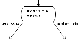
Figure 6.3. Process Snippet for Updating ERP Example
public class AmountUpdate implements ActionHandler {
  public void execute(ExecutionContext ctx) throws Exception {
    // business logic
    Float erpAmount = ...get amount from erp-system...;
    Float processAmount = (Float) ctx.getContextInstance().getVariable("amount");
    float result = erpAmount.floatValue() + processAmount.floatValue();
    ...update erp-system with the result...;

    // graph execution propagation
    if (result > 5000) {
      ctx.leaveNode(ctx, "big amounts");
    } else {
      ctx.leaveNode(ctx, "small amounts");
    }
  }
}
Note
One can also create and join tokens in custom node implementations. To learn how to do this, study the Fork and Join node implementation in the jBPM source code.
6.10. Graph Execution
The Business Process Manager's graph execution model is based on an interpretation of the process definition and the "chain of command" pattern.
The process definition data is stored in the database and is used during process execution.
Note
Be aware that Hibernate's second level cache is used so as to avoid loading definition information at run-time. Since the process definitions do not change, Hibernate can cache them in memory.
The "chain of command pattern" makes each node in the graph responsible for passing on the process execution. If a node does not pass it on, it behaves as though it were a
wait state.
Let the execution start on process instances and it will continue until it enters a
wait state.
A token represents a path of execution. It has a pointer to a node in the process graph. During
wait state, the tokens can be made to persist in the database.
This algorithm is used to calculate the execution of a token. Execution starts when a signal is sent to the tokenand it is then passed over the transitions and nodes via the chain of command pattern. These are the relevant methods:
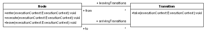
Figure 6.4. The graph execution-related methods
When a token is in a node, signals can be sent to it. A signal is treated as an instruction to start execution and must, therefore, specify a
leaving transition from the token's current node. The first transition is the default. In a signal to a token, it takes its current node and calls the Node.leave(ExecutionContext,Transition) method. (It is best to think of the ExecutionContext as a token because the main object in it is a token.) The Node.leave(ExecutionContext,Transition) method will fire the node-leave event and call the Transition.take(ExecutionContext). That method will then run the transition event and call the Node.enter(ExecutionContext) on the transition's destination node. That method will then fire the node-enter event and call the Node.execute(ExecutionContext).
Every type of node has its own behaviour, these being implemented via the
execute method. Each node is responsible for passing on the graph execution by calling the Node.leave(ExecutionContext,Transition) again. In summary:
Token.signal(Transition)Node.leave(ExecutionContext,Transition)Transition.take(ExecutionContext)Node.enter(ExecutionContext)Node.execute(ExecutionContext)
Note
The next state, including the invocation of the actions, is calculated via the client's thread. A common misconception is that all calculations must be undertaken in this way. Rather, as is the case with any asynchronous invocation, one can use asynchronous messaging (via Java Message Service) for that. When the message is sent in the same transaction as the process instance update, all synchronization issues are handled correctly. Some workflow systems use asynchronous messaging between all nodes in the graph but, in high throughput environments, this algorithm gives much more control and flexibility to those wishing to maximise business process performance.
6.11. Transaction Demarcation
As explained in Section 6.10, “ Graph Execution ”, the Business Process Manager runs the process in the thread of the client and is, by nature, synchronous. In practice, this means that the
token.signal() or taskInstance.end() will only return when the process has entered a new wait state.
Note
To learn more about the jPDL feature being described in this section, read Chapter 10, Asynchronous Continuations .
In most situations this is the most straightforward approach because one can easily bind the the process execution to server-side transactions: the process moves from one state to the next in the space of one transaction.
Sometimes, in-process calculations take a lot of time, so this behavior might be undesirable. To cope with this issue, the Business Process Manager includes an asynchronous messaging system that allows it to continue a process in a manner, which is, as the name implies, asynchronous. (Of course, in a Java enterprise environment, jBPM can be configured to use a Java Message Service broker instead of the in-built messaging system.)
jPDL supports the
async="true" attribute in every node. Asynchronous nodes will not be executed in the thread of the client. Instead, a message is sent over the asynchronous messaging system and the thread is returned to the client (in other words, token.signal() or taskInstance.end() will be returned.)
The Business Process Manager's client code can now commit the transaction. Send messages in the same transaction as that containing the process updates. (The overall result of such a transaction will be that the token is moved to the next node (which has not yet been executed) and a
org.jbpm.command.ExecuteNodeCommand message will be sent from the asynchronous messaging system to the jBPM Command Executor. This reads the commands from the queue and executes them. In the case of the org.jbpm.command.ExecuteNodeCommand, the process will be continued when the node is executed. (Each command is executed in a separate transaction.)
Important
Ensure that a
jBPM Command Executor is running so that asynchronous processes can continue. Do so by configuring the web application's CommandExecutionServlet.
Note
Process modelers do not need to be excessively concerned with asynchronous messaging. The main point to remember is transaction demarcation: by default, the Business Process Manager will operate in the client transaction, undertaking the whole calculation until the process enters a
wait state. (Use async="true" to demarcate a transaction in the process.)
Here is an example:
<start-state>
  <transition to="one" />
</start-state>
<node async="true" name="one">
  <action class="com...MyAutomaticAction" />
  <transition to="two" />
</node>
<node async="true" name="two">
  <action class="com...MyAutomaticAction" />
  <transition to="three" />
</node>
<node async="true" name="three">
  <action class="com...MyAutomaticAction" />
  <transition to="end" />
</node>
<end-state name="end" />
...
The client code needed to both start and resume process executions is exactly the same as that needed for normal synchronous processes.
//start a transaction
JbpmContext jbpmContext = jbpmConfiguration.createContext();
try {
  ProcessInstance processInstance =
    jbpmContext.newProcessInstance("my async process");
  processInstance.signal();
  jbpmContext.save(processInstance);
} finally {
  jbpmContext.close();
}
After this first transaction occurs, the process execution's
root token will point to node one and an ExecuteNodeCommand message is sent to the command executor.
In a subsequent transaction, the command executor will read the message from the queue and execute
node one. The action can decide to pass the execution on or enter a wait state. If it chooses to pass it on, the transaction will be ended when the execution arrives at node two.