Questo contenuto non è disponibile nella lingua selezionata.
Post-installation configuration
Day 2 operations for OpenShift Container Platform
Abstract
Chapter 1. Post-installation cluster tasks
After installing OpenShift Container Platform, you can further expand and customize your cluster to your requirements.
1.1. Adjust worker nodes
If you incorrectly sized the worker nodes during deployment, adjust them by creating one or more new machine sets, scale them up, then scale the original machine set down before removing them.
1.1.1. Understanding the difference between machine sets and the machine config pool
MachineSet objects describe OpenShift Container Platform nodes with respect to the cloud or machine provider.
The MachineConfigPool object allows MachineConfigController components to define and provide the status of machines in the context of upgrades.
The MachineConfigPool object allows users to configure how upgrades are rolled out to the OpenShift Container Platform nodes in the machine config pool.
The NodeSelector object can be replaced with a reference to the MachineSet object.
1.1.2. Scaling a machine set manually
If you must add or remove an instance of a machine in a machine set, you can manually scale the machine set.
This guidance is relevant to fully automated, installer-provisioned infrastructure installations. Customized, user-provisioned infrastructure installations does not have machine sets.
Prerequisites
-
Install an OpenShift Container Platform cluster and the
occommand line. -
Log in to
ocas a user withcluster-adminpermission.
Procedure
View the machine sets that are in the cluster:
$ oc get machinesets -n openshift-machine-apiThe machine sets are listed in the form of
<clusterid>-worker-<aws-region-az>.Scale the machine set:
$ oc scale --replicas=2 machineset <machineset> -n openshift-machine-apiOr:
$ oc edit machineset <machineset> -n openshift-machine-apiYou can scale the machine set up or down. It takes several minutes for the new machines to be available.
1.1.3. The machine set deletion policy
Random, Newest, and Oldest are the three supported deletion options. The default is Random, meaning that random machines are chosen and deleted when scaling machine sets down. The deletion policy can be set according to the use case by modifying the particular machine set:
spec:
  deletePolicy: <delete_policy>
  replicas: <desired_replica_count>
Specific machines can also be prioritized for deletion by adding the annotation machine.openshift.io/cluster-api-delete-machine to the machine of interest, regardless of the deletion policy.
By default, the OpenShift Container Platform router pods are deployed on workers. Because the router is required to access some cluster resources, including the web console, do not scale the worker machine set to 0 unless you first relocate the router pods.
Custom machine sets can be used for use cases requiring that services run on specific nodes and that those services are ignored by the controller when the worker machine sets are scaling down. This prevents service disruption.
1.1.4. Creating default cluster-wide node selectors
You can use default cluster-wide node selectors on pods together with labels on nodes to constrain all pods created in a cluster to specific nodes.
With cluster-wide node selectors, when you create a pod in that cluster, OpenShift Container Platform adds the default node selectors to the pod and schedules the pod on nodes with matching labels.
You configure cluster-wide node selectors by editing the Scheduler Operator custom resource (CR). You add labels to a node, a machine set, or a machine config. Adding the label to the machine set ensures that if the node or machine goes down, new nodes have the label. Labels added to a node or machine config do not persist if the node or machine goes down.
You can add additional key/value pairs to a pod. But you cannot add a different value for a default key.
Procedure
To add a default cluster-wide node selector:
Edit the Scheduler Operator CR to add the default cluster-wide node selectors:
$ oc edit scheduler clusterExample Scheduler Operator CR with a node selector
apiVersion: config.openshift.io/v1
kind: Scheduler
metadata:
  name: cluster
...

spec:
  defaultNodeSelector: type=user-node,region=east
1 mastersSchedulable: false policy: name: ""- 1
- Add a node selector with the appropriate
<key>:<value>pairs.
After making this change, wait for the pods in the
openshift-kube-apiserverproject to redeploy. This can take several minutes. The default cluster-wide node selector does not take effect until the pods redeploy.Add labels to a node by using a machine set or editing the node directly:
Use a machine set to add labels to nodes managed by the machine set when a node is created:
Run the following command to add labels to a
MachineSetobject:$ oc patch MachineSet <name> --type='json' -p='[{"op":"add","path":"/spec/template/spec/metadata/labels", "value":{"<key>"="<value>","<key>"="<value>"}}]' -n openshift-machine-api1 - 1
- Add a
<key>/<value>pair for each label.
For example:
$ oc patch MachineSet ci-ln-l8nry52-f76d1-hl7m7-worker-c --type='json' -p='[{"op":"add","path":"/spec/template/spec/metadata/labels", "value":{"type":"user-node","region":"east"}}]' -n openshift-machine-apiVerify that the labels are added to the
MachineSetobject by using theoc editcommand:For example:
$ oc edit MachineSet ci-ln-l8nry52-f76d1-hl7m7-worker-c -n openshift-machine-apiExample output
apiVersion: machine.openshift.io/v1beta1
kind: MachineSet
metadata:
...
spec:
...
  template:
    metadata:
...
    spec:
      metadata:
        labels:
          region: east
          type: user-node
Redeploy the nodes associated with that machine set by scaling down to
0and scaling up the nodes:For example:
$ oc scale --replicas=0 MachineSet ci-ln-l8nry52-f76d1-hl7m7-worker-c -n openshift-machine-api$ oc scale --replicas=1 MachineSet ci-ln-l8nry52-f76d1-hl7m7-worker-c -n openshift-machine-apiWhen the nodes are ready and available, verify that the label is added to the nodes by using the
oc getcommand:$ oc get nodes -l <key>=<value>For example:
$ oc get nodes -l type=user-nodeExample output
NAME                                       STATUS   ROLES    AGE   VERSION
ci-ln-l8nry52-f76d1-hl7m7-worker-c-vmqzp   Ready    worker   61s   v1.18.3+002a51f
Add labels directly to a node:
Edit the
Nodeobject for the node:$ oc label nodes <name> <key>=<value>For example, to label a node:
$ oc label nodes ci-ln-l8nry52-f76d1-hl7m7-worker-b-tgq49 type=user-node region=eastVerify that the labels are added to the node using the
oc getcommand:$ oc get nodes -l <key>=<value>,<key>=<value>For example:
$ oc get nodes -l type=user-node,region=eastExample output
NAME                                       STATUS   ROLES    AGE   VERSION
ci-ln-l8nry52-f76d1-hl7m7-worker-b-tgq49   Ready    worker   17m   v1.18.3+002a51f
1.2. Creating infrastructure machine sets for production environments
In a production deployment, deploy at least three machine sets to hold infrastructure components. Both the logging aggregation solution and the service mesh deploy Elasticsearch, and Elasticsearch requires three instances that are installed on different nodes. For high availability, install deploy these nodes to different availability zones. Since you need different machine sets for each availability zone, create at least three machine sets.
For sample machine sets that you can use with these procedures, see Creating machine sets for different clouds.
1.2.1. Creating a machine set
In addition to the ones created by the installation program, you can create your own machine sets to dynamically manage the machine compute resources for specific workloads of your choice.
Prerequisites
- Deploy an OpenShift Container Platform cluster.
-
Install the OpenShift CLI (
oc). -
Log in to
ocas a user withcluster-adminpermission.
Procedure
Create a new YAML file that contains the machine set custom resource (CR) sample and is named
<file_name>.yaml.Ensure that you set the
<clusterID>and<role>parameter values.If you are not sure about which value to set for a specific field, you can check an existing machine set from your cluster.
$ oc get machinesets -n openshift-machine-apiExample output
NAME                                DESIRED   CURRENT   READY   AVAILABLE   AGE
agl030519-vplxk-worker-us-east-1a   1         1         1       1           55m
agl030519-vplxk-worker-us-east-1b   1         1         1       1           55m
agl030519-vplxk-worker-us-east-1c   1         1         1       1           55m
agl030519-vplxk-worker-us-east-1d   0         0                             55m
agl030519-vplxk-worker-us-east-1e   0         0                             55m
agl030519-vplxk-worker-us-east-1f   0         0                             55m
Check values of a specific machine set:
$ oc get machineset <machineset_name> -n \
     openshift-machine-api -o yaml
Example output
...
template:
    metadata:
      labels:
        machine.openshift.io/cluster-api-cluster: agl030519-vplxk
1 machine.openshift.io/cluster-api-machine-role: worker2 machine.openshift.io/cluster-api-machine-type: worker machine.openshift.io/cluster-api-machineset: agl030519-vplxk-worker-us-east-1a
Create the new
MachineSetCR:$ oc create -f <file_name>.yamlView the list of machine sets:
$ oc get machineset -n openshift-machine-apiExample output
NAME                                DESIRED   CURRENT   READY   AVAILABLE   AGE
agl030519-vplxk-infra-us-east-1a    1         1         1       1           11m
agl030519-vplxk-worker-us-east-1a   1         1         1       1           55m
agl030519-vplxk-worker-us-east-1b   1         1         1       1           55m
agl030519-vplxk-worker-us-east-1c   1         1         1       1           55m
agl030519-vplxk-worker-us-east-1d   0         0                             55m
agl030519-vplxk-worker-us-east-1e   0         0                             55m
agl030519-vplxk-worker-us-east-1f   0         0                             55m
When the new machine set is available, the
DESIREDandCURRENTvalues match. If the machine set is not available, wait a few minutes and run the command again.
1.2.2. Creating an infrastructure node
See Creating infrastructure machine sets for installer-provisioned infrastructure environments or for any cluster where the master nodes are managed by the machine API.
Requirements of the cluster dictate that infrastructure, also called infra nodes, be provisioned. The installer only provides provisions for master and worker nodes. Worker nodes can be designated as infrastructure nodes or application, also called app, nodes through labeling.
Procedure
Add a label to the worker node that you want to act as application node:
$ oc label node <node-name> node-role.kubernetes.io/app=""Add a label to the worker nodes that you want to act as infrastructure nodes:
$ oc label node <node-name> node-role.kubernetes.io/infra=""Check to see if applicable nodes now have the
infrarole andapproles:$ oc get nodesCreate a default node selector so that pods without a node selector are assigned a subset of nodes to be deployed on, for example by default deployment in worker nodes. As an example, the
defaultNodeSelectorto deploy pods on worker nodes by default would look like:defaultNodeSelector: node-role.kubernetes.io/app=-
Move infrastructure resources to the newly labeled
infranodes.
1.2.3. Creating a machine config pool for infrastructure machines
If you need infrastructure machines to have dedicated configurations, you must create an infra pool.
Procedure
Add a label to the node you want to assign as the infra node with a specific label:
$ oc label node <node_name> <label>$ oc label node ci-ln-n8mqwr2-f76d1-xscn2-worker-c-6fmtx node-role.kubernetes.io/infra=Create a machine config pool that contains both the worker role and your custom role as machine config selector:
$ cat infra.mcp.yamlExample output
apiVersion: machineconfiguration.openshift.io/v1
kind: MachineConfigPool
metadata:
  name: infra
spec:
  machineConfigSelector:
    matchExpressions:
      - {key: machineconfiguration.openshift.io/role, operator: In, values: [worker,infra]}
1 nodeSelector: matchLabels: node-role.kubernetes.io/infra: ""2 NoteCustom machine config pools inherit machine configs from the worker pool. Custom pools use any machine config targeted for the worker pool, but add the ability to also deploy changes that are targeted at only the custom pool. Because a custom pool inherits resources from the worker pool, any change to the worker pool also affects the custom pool.
After you have the YAML file, you can create the machine config pool:
$ oc create -f infra.mcp.yamlCheck the machine configs to ensure that the infrastructure configuration rendered successfully:
$ oc get machineconfigExample output
NAME                                                        GENERATEDBYCONTROLLER                      IGNITIONVERSION   CREATED
00-master                                                   365c1cfd14de5b0e3b85e0fc815b0060f36ab955   2.2.0             31d
00-worker                                                   365c1cfd14de5b0e3b85e0fc815b0060f36ab955   2.2.0             31d
01-master-container-runtime                                 365c1cfd14de5b0e3b85e0fc815b0060f36ab955   2.2.0             31d
01-master-kubelet                                           365c1cfd14de5b0e3b85e0fc815b0060f36ab955   2.2.0             31d
01-worker-container-runtime                                 365c1cfd14de5b0e3b85e0fc815b0060f36ab955   2.2.0             31d
01-worker-kubelet                                           365c1cfd14de5b0e3b85e0fc815b0060f36ab955   2.2.0             31d
99-master-1ae2a1e0-a115-11e9-8f14-005056899d54-registries   365c1cfd14de5b0e3b85e0fc815b0060f36ab955   2.2.0             31d
99-master-ssh                                                                                          2.2.0             31d
99-worker-1ae64748-a115-11e9-8f14-005056899d54-registries   365c1cfd14de5b0e3b85e0fc815b0060f36ab955   2.2.0             31d
99-worker-ssh                                                                                          2.2.0             31d
rendered-infra-4e48906dca84ee702959c71a53ee80e7             365c1cfd14de5b0e3b85e0fc815b0060f36ab955   2.2.0             19s
rendered-master-072d4b2da7f88162636902b074e9e28e            5b6fb8349a29735e48446d435962dec4547d3090   2.2.0             31d
rendered-master-3e88ec72aed3886dec061df60d16d1af            02c07496ba0417b3e12b78fb32baf6293d314f79   2.2.0             31d
rendered-master-419bee7de96134963a15fdf9dd473b25            365c1cfd14de5b0e3b85e0fc815b0060f36ab955   2.2.0             17d
rendered-master-53f5c91c7661708adce18739cc0f40fb            365c1cfd14de5b0e3b85e0fc815b0060f36ab955   2.2.0             13d
rendered-master-a6a357ec18e5bce7f5ac426fc7c5ffcd            365c1cfd14de5b0e3b85e0fc815b0060f36ab955   2.2.0             7d3h
rendered-master-dc7f874ec77fc4b969674204332da037            5b6fb8349a29735e48446d435962dec4547d3090   2.2.0             31d
rendered-worker-1a75960c52ad18ff5dfa6674eb7e533d            5b6fb8349a29735e48446d435962dec4547d3090   2.2.0             31d
rendered-worker-2640531be11ba43c61d72e82dc634ce6            5b6fb8349a29735e48446d435962dec4547d3090   2.2.0             31d
rendered-worker-4e48906dca84ee702959c71a53ee80e7            365c1cfd14de5b0e3b85e0fc815b0060f36ab955   2.2.0             7d3h
rendered-worker-4f110718fe88e5f349987854a1147755            365c1cfd14de5b0e3b85e0fc815b0060f36ab955   2.2.0             17d
rendered-worker-afc758e194d6188677eb837842d3b379            02c07496ba0417b3e12b78fb32baf6293d314f79   2.2.0             31d
rendered-worker-daa08cc1e8f5fcdeba24de60cd955cc3            365c1cfd14de5b0e3b85e0fc815b0060f36ab955   2.2.0             13d
You should see a new machine config, with the
rendered-infra-*prefix.Optional: To deploy changes to a custom pool, create a machine config that uses the custom pool name as the label, such as
infra. Note that this is not required and only shown for instructional purposes. In this manner, you can apply any custom configurations specific to only your infra nodes.NoteAfter you create the new machine config pool, the MCO generates a new rendered config for that pool, and associated nodes of that pool reboot to apply the new configuration.
Create a machine config:
$ cat infra.mc.yamlExample output
apiVersion: machineconfiguration.openshift.io/v1
kind: MachineConfig
metadata:
  labels:
    machineconfiguration.openshift.io/role: infra
1 name: 51-infra spec: config: ignition: version: 2.2.0 storage: files: - contents: source: data:,infra filesystem: root mode: 0644 path: /etc/infratest- 1
- Add the label you added to the node as a
nodeSelector.
Apply the machine config to the infra-labeled nodes:
$ oc create -f infra.mc.yaml
Confirm that your new machine config pool is available:
$ oc get mcpExample output
NAME     CONFIG                                             UPDATED   UPDATING   DEGRADED   MACHINECOUNT   READYMACHINECOUNT   UPDATEDMACHINECOUNT   DEGRADEDMACHINECOUNT   AGE
infra    rendered-infra-60e35c2e99f42d976e084fa94da4d0fc    True      False      False      1              1                   1                     0                      4m20s
master   rendered-master-9360fdb895d4c131c7c4bebbae099c90   True      False      False      3              3                   3                     0                      91m
worker   rendered-worker-60e35c2e99f42d976e084fa94da4d0fc   True      False      False      2              2                   2                     0                      91m
In this example, a worker node was changed to an infra node.
Additional resources
- See Node configuration management with machine config pools for more information on grouping infra machines in a custom pool.
1.3. Assigning machine set resources to infrastructure nodes
After creating an infrastructure machine set, the worker and infra roles are applied to new infra nodes. Nodes with the infra role are not counted toward the total number of subscriptions that are required to run the environment, even when the worker role is also applied.
However, when an infra node is assigned the worker role, there is a chance that user workloads can get assigned inadvertently to the infra node. To avoid this, you can apply a taint to the infra node and tolerations for the pods that you want to control.
1.3.1. Binding infrastructure node workloads using taints and tolerations
If you have an infra node that has the infra and worker roles assigned, you must configure the node so that user workloads are not assigned to it.
It is recommended that you preserve the dual infra,worker label that is created for infra nodes and use taints and tolerations to manage nodes that user workloads are scheduled on. If you remove the worker label from the node, you must create a custom pool to manage it. A node with a label other than master or worker is not recognized by the MCO without a custom pool. Maintaining the worker label allows the node to be managed by the default worker machine config pool, if no custom pools that select the custom label exists. The infra label communicates to the cluster that it does not count toward the total number of subscriptions.
Prerequisites
-
Configure additional
MachineSetobjects in your OpenShift Container Platform cluster.
Procedure
Add a taint to the infra node to prevent scheduling user workloads on it:
Determine if the node has the taint:
$ oc describe nodes <node_name>Sample output
oc describe node ci-ln-iyhx092-f76d1-nvdfm-worker-b-wln2l
Name:               ci-ln-iyhx092-f76d1-nvdfm-worker-b-wln2l
Roles:              worker
 ...
Taints:             node-role.kubernetes.io/infra:NoSchedule
 ...
This example shows that the node has a taint. You can proceed with adding a toleration to your pod in the next step.
If you have not configured a taint to prevent scheduling user workloads on it:
$ oc adm taint nodes <node_name> <key>:<effect>For example:
$ oc adm taint nodes node1 node-role.kubernetes.io/infra:NoScheduleThis example places a taint on
node1that has keynode-role.kubernetes.io/infraand taint effectNoSchedule. Nodes with theNoScheduleeffect schedule only pods that tolerate the taint, but allow existing pods to remain scheduled on the node.NoteIf a descheduler is used, pods violating node taints could be evicted from the cluster.
Add tolerations for the pod configurations you want to schedule on the infra node, like router, registry, and monitoring workloads. Add the following code to the
Podobject specification:tolerations: - effect: NoSchedule1 key: node-role.kubernetes.io/infra2 operator: Exists3 This toleration matches the taint created by the
oc adm taintcommand. A pod with this toleration can be scheduled onto the infra node.NoteMoving pods for an Operator installed via OLM to an infra node is not always possible. The capability to move Operator pods depends on the configuration of each Operator.
- Schedule the pod to the infra node using a scheduler. See the documentation for Controlling pod placement onto nodes for details.
Additional resources
- See Controlling pod placement using the scheduler for general information on scheduling a pod to a node.
1.4. Moving resources to infrastructure machine sets
Some of the infrastructure resources are deployed in your cluster by default. You can move them to the infrastructure machine sets that you created.
1.4.1. Moving the router
You can deploy the router pod to a different machine set. By default, the pod is deployed to a worker node.
Prerequisites
- Configure additional machine sets in your OpenShift Container Platform cluster.
Procedure
View the
IngressControllercustom resource for the router Operator:$ oc get ingresscontroller default -n openshift-ingress-operator -o yamlThe command output resembles the following text:
apiVersion: operator.openshift.io/v1
kind: IngressController
metadata:
  creationTimestamp: 2019-04-18T12:35:39Z
  finalizers:
  - ingresscontroller.operator.openshift.io/finalizer-ingresscontroller
  generation: 1
  name: default
  namespace: openshift-ingress-operator
  resourceVersion: "11341"
  selfLink: /apis/operator.openshift.io/v1/namespaces/openshift-ingress-operator/ingresscontrollers/default
  uid: 79509e05-61d6-11e9-bc55-02ce4781844a
spec: {}
status:
  availableReplicas: 2
  conditions:
  - lastTransitionTime: 2019-04-18T12:36:15Z
    status: "True"
    type: Available
  domain: apps.<cluster>.example.com
  endpointPublishingStrategy:
    type: LoadBalancerService
  selector: ingresscontroller.operator.openshift.io/deployment-ingresscontroller=default
Edit the
ingresscontrollerresource and change thenodeSelectorto use theinfralabel:$ oc edit ingresscontroller default -n openshift-ingress-operatorAdd the
nodeSelectorstanza that references theinfralabel to thespecsection, as shown:spec: nodePlacement: nodeSelector: matchLabels: node-role.kubernetes.io/infra: ""Confirm that the router pod is running on the
infranode.View the list of router pods and note the node name of the running pod:
$ oc get pod -n openshift-ingress -o wideExample output
NAME                              READY     STATUS        RESTARTS   AGE       IP           NODE                           NOMINATED NODE   READINESS GATES
router-default-86798b4b5d-bdlvd   1/1      Running       0          28s       10.130.2.4   ip-10-0-217-226.ec2.internal   <none>           <none>
router-default-955d875f4-255g8    0/1      Terminating   0          19h       10.129.2.4   ip-10-0-148-172.ec2.internal   <none>           <none>
In this example, the running pod is on the
ip-10-0-217-226.ec2.internalnode.View the node status of the running pod:
$ oc get node <node_name>1 - 1
- Specify the
<node_name>that you obtained from the pod list.
Example output
NAME                          STATUS  ROLES         AGE   VERSION
ip-10-0-217-226.ec2.internal  Ready   infra,worker  17h   v1.18.3
Because the role list includes
infra, the pod is running on the correct node.
1.4.2. Moving the default registry
You configure the registry Operator to deploy its pods to different nodes.
Prerequisites
- Configure additional machine sets in your OpenShift Container Platform cluster.
Procedure
View the
config/instanceobject:$ oc get configs.imageregistry.operator.openshift.io/cluster -o yamlExample output
apiVersion: imageregistry.operator.openshift.io/v1
kind: Config
metadata:
  creationTimestamp: 2019-02-05T13:52:05Z
  finalizers:
  - imageregistry.operator.openshift.io/finalizer
  generation: 1
  name: cluster
  resourceVersion: "56174"
  selfLink: /apis/imageregistry.operator.openshift.io/v1/configs/cluster
  uid: 36fd3724-294d-11e9-a524-12ffeee2931b
spec:
  httpSecret: d9a012ccd117b1e6616ceccb2c3bb66a5fed1b5e481623
  logging: 2
  managementState: Managed
  proxy: {}
  replicas: 1
  requests:
    read: {}
    write: {}
  storage:
    s3:
      bucket: image-registry-us-east-1-c92e88cad85b48ec8b312344dff03c82-392c
      region: us-east-1
status:
...
Edit the
config/instanceobject:$ oc edit configs.imageregistry.operator.openshift.io/clusterAdd the following lines of text the
specsection of the object:nodeSelector: node-role.kubernetes.io/infra: ""Verify the registry pod has been moved to the infrastructure node.
Run the following command to identify the node where the registry pod is located:
$ oc get pods -o wide -n openshift-image-registryConfirm the node has the label you specified:
$ oc describe node <node_name>Review the command output and confirm that
node-role.kubernetes.io/infrais in theLABELSlist.
1.4.3. Moving the monitoring solution
By default, the Prometheus Cluster Monitoring stack, which contains Prometheus, Grafana, and AlertManager, is deployed to provide cluster monitoring. It is managed by the Cluster Monitoring Operator. To move its components to different machines, you create and apply a custom config map.
Procedure
Save the following
ConfigMapdefinition as thecluster-monitoring-configmap.yamlfile:apiVersion: v1 kind: ConfigMap metadata: name: cluster-monitoring-config namespace: openshift-monitoring data: config.yaml: |+ alertmanagerMain: nodeSelector: node-role.kubernetes.io/infra: "" prometheusK8s: nodeSelector: node-role.kubernetes.io/infra: "" prometheusOperator: nodeSelector: node-role.kubernetes.io/infra: "" grafana: nodeSelector: node-role.kubernetes.io/infra: "" k8sPrometheusAdapter: nodeSelector: node-role.kubernetes.io/infra: "" kubeStateMetrics: nodeSelector: node-role.kubernetes.io/infra: "" telemeterClient: nodeSelector: node-role.kubernetes.io/infra: "" openshiftStateMetrics: nodeSelector: node-role.kubernetes.io/infra: "" thanosQuerier: nodeSelector: node-role.kubernetes.io/infra: ""Running this config map forces the components of the monitoring stack to redeploy to infrastructure nodes.
Apply the new config map:
$ oc create -f cluster-monitoring-configmap.yamlWatch the monitoring pods move to the new machines:
$ watch 'oc get pod -n openshift-monitoring -o wide'If a component has not moved to the
infranode, delete the pod with this component:$ oc delete pod -n openshift-monitoring <pod>The component from the deleted pod is re-created on the
infranode.
1.4.4. Moving the cluster logging resources
You can configure the Cluster Logging Operator to deploy the pods for any or all of the Cluster Logging components, Elasticsearch, Kibana, and Curator to different nodes. You cannot move the Cluster Logging Operator pod from its installed location.
For example, you can move the Elasticsearch pods to a separate node because of high CPU, memory, and disk requirements.
Prerequisites
- Cluster logging and Elasticsearch must be installed. These features are not installed by default.
Procedure
Edit the
ClusterLoggingcustom resource (CR) in theopenshift-loggingproject:$ oc edit ClusterLogging instanceapiVersion: logging.openshift.io/v1 kind: ClusterLogging ... spec: collection: logs: fluentd: resources: null type: fluentd curation: curator: nodeSelector:1 node-role.kubernetes.io/infra: '' resources: null schedule: 30 3 * * * type: curator logStore: elasticsearch: nodeCount: 3 nodeSelector:2 node-role.kubernetes.io/infra: '' redundancyPolicy: SingleRedundancy resources: limits: cpu: 500m memory: 16Gi requests: cpu: 500m memory: 16Gi storage: {} type: elasticsearch managementState: Managed visualization: kibana: nodeSelector:3 node-role.kubernetes.io/infra: '' proxy: resources: null replicas: 1 resources: null type: kibana ...
Verification
To verify that a component has moved, you can use the oc get pod -o wide command.
For example:
You want to move the Kibana pod from the
ip-10-0-147-79.us-east-2.compute.internalnode:$ oc get pod kibana-5b8bdf44f9-ccpq9 -o wideExample output
NAME                      READY   STATUS    RESTARTS   AGE   IP            NODE                                        NOMINATED NODE   READINESS GATES
kibana-5b8bdf44f9-ccpq9   2/2     Running   0          27s   10.129.2.18   ip-10-0-147-79.us-east-2.compute.internal   <none>           <none>
You want to move the Kibana Pod to the
ip-10-0-139-48.us-east-2.compute.internalnode, a dedicated infrastructure node:$ oc get nodesExample output
NAME                                         STATUS   ROLES          AGE   VERSION
ip-10-0-133-216.us-east-2.compute.internal   Ready    master         60m   v1.18.3
ip-10-0-139-146.us-east-2.compute.internal   Ready    master         60m   v1.18.3
ip-10-0-139-192.us-east-2.compute.internal   Ready    worker         51m   v1.18.3
ip-10-0-139-241.us-east-2.compute.internal   Ready    worker         51m   v1.18.3
ip-10-0-147-79.us-east-2.compute.internal    Ready    worker         51m   v1.18.3
ip-10-0-152-241.us-east-2.compute.internal   Ready    master         60m   v1.18.3
ip-10-0-139-48.us-east-2.compute.internal    Ready    infra          51m   v1.18.3
Note that the node has a
node-role.kubernetes.io/infra: ''label:$ oc get node ip-10-0-139-48.us-east-2.compute.internal -o yamlExample output
kind: Node
apiVersion: v1
metadata:
  name: ip-10-0-139-48.us-east-2.compute.internal
  selfLink: /api/v1/nodes/ip-10-0-139-48.us-east-2.compute.internal
  uid: 62038aa9-661f-41d7-ba93-b5f1b6ef8751
  resourceVersion: '39083'
  creationTimestamp: '2020-04-13T19:07:55Z'
  labels:
    node-role.kubernetes.io/infra: ''
...
To move the Kibana pod, edit the
ClusterLoggingCR to add a node selector:apiVersion: logging.openshift.io/v1 kind: ClusterLogging ... spec: ... visualization: kibana: nodeSelector:1 node-role.kubernetes.io/infra: '' proxy: resources: null replicas: 1 resources: null type: kibana- 1
- Add a node selector to match the label in the node specification.
After you save the CR, the current Kibana pod is terminated and new pod is deployed:
$ oc get podsExample output
NAME                                            READY   STATUS        RESTARTS   AGE
cluster-logging-operator-84d98649c4-zb9g7       1/1     Running       0          29m
elasticsearch-cdm-hwv01pf7-1-56588f554f-kpmlg   2/2     Running       0          28m
elasticsearch-cdm-hwv01pf7-2-84c877d75d-75wqj   2/2     Running       0          28m
elasticsearch-cdm-hwv01pf7-3-f5d95b87b-4nx78    2/2     Running       0          28m
fluentd-42dzz                                   1/1     Running       0          28m
fluentd-d74rq                                   1/1     Running       0          28m
fluentd-m5vr9                                   1/1     Running       0          28m
fluentd-nkxl7                                   1/1     Running       0          28m
fluentd-pdvqb                                   1/1     Running       0          28m
fluentd-tflh6                                   1/1     Running       0          28m
kibana-5b8bdf44f9-ccpq9                         2/2     Terminating   0          4m11s
kibana-7d85dcffc8-bfpfp                         2/2     Running       0          33s
The new pod is on the
ip-10-0-139-48.us-east-2.compute.internalnode:$ oc get pod kibana-7d85dcffc8-bfpfp -o wideExample output
NAME                      READY   STATUS        RESTARTS   AGE   IP            NODE                                        NOMINATED NODE   READINESS GATES
kibana-7d85dcffc8-bfpfp   2/2     Running       0          43s   10.131.0.22   ip-10-0-139-48.us-east-2.compute.internal   <none>           <none>
After a few moments, the original Kibana pod is removed.
$ oc get podsExample output
NAME                                            READY   STATUS    RESTARTS   AGE
cluster-logging-operator-84d98649c4-zb9g7       1/1     Running   0          30m
elasticsearch-cdm-hwv01pf7-1-56588f554f-kpmlg   2/2     Running   0          29m
elasticsearch-cdm-hwv01pf7-2-84c877d75d-75wqj   2/2     Running   0          29m
elasticsearch-cdm-hwv01pf7-3-f5d95b87b-4nx78    2/2     Running   0          29m
fluentd-42dzz                                   1/1     Running   0          29m
fluentd-d74rq                                   1/1     Running   0          29m
fluentd-m5vr9                                   1/1     Running   0          29m
fluentd-nkxl7                                   1/1     Running   0          29m
fluentd-pdvqb                                   1/1     Running   0          29m
fluentd-tflh6                                   1/1     Running   0          29m
kibana-7d85dcffc8-bfpfp                         2/2     Running   0          62s
1.5. About the cluster autoscaler
The cluster autoscaler adjusts the size of an OpenShift Container Platform cluster to meet its current deployment needs. It uses declarative, Kubernetes-style arguments to provide infrastructure management that does not rely on objects of a specific cloud provider. The cluster autoscaler has a cluster scope, and is not associated with a particular namespace.
The cluster autoscaler increases the size of the cluster when there are pods that failed to schedule on any of the current nodes due to insufficient resources or when another node is necessary to meet deployment needs. The cluster autoscaler does not increase the cluster resources beyond the limits that you specify.
Ensure that the maxNodesTotal value in the ClusterAutoscaler resource definition that you create is large enough to account for the total possible number of machines in your cluster. This value must encompass the number of control plane machines and the possible number of compute machines that you might scale to.
The cluster autoscaler decreases the size of the cluster when some nodes are consistently not needed for a significant period, such as when it has low resource use and all of its important pods can fit on other nodes.
If the following types of pods are present on a node, the cluster autoscaler will not remove the node:
- Pods with restrictive pod disruption budgets (PDBs).
- Kube-system pods that do not run on the node by default.
- Kube-system pods that do not have a PDB or have a PDB that is too restrictive.
- Pods that are not backed by a controller object such as a deployment, replica set, or stateful set.
- Pods with local storage.
- Pods that cannot be moved elsewhere because of a lack of resources, incompatible node selectors or affinity, matching anti-affinity, and so on.
-
Unless they also have a
"cluster-autoscaler.kubernetes.io/safe-to-evict": "true"annotation, pods that have a"cluster-autoscaler.kubernetes.io/safe-to-evict": "false"annotation.
If you configure the cluster autoscaler, additional usage restrictions apply:
- Do not modify the nodes that are in autoscaled node groups directly. All nodes within the same node group have the same capacity and labels and run the same system pods.
- Specify requests for your pods.
- If you have to prevent pods from being deleted too quickly, configure appropriate PDBs.
- Confirm that your cloud provider quota is large enough to support the maximum node pools that you configure.
- Do not run additional node group autoscalers, especially the ones offered by your cloud provider.
The horizontal pod autoscaler (HPA) and the cluster autoscaler modify cluster resources in different ways. The HPA changes the deployment’s or replica set’s number of replicas based on the current CPU load. If the load increases, the HPA creates new replicas, regardless of the amount of resources available to the cluster. If there are not enough resources, the cluster autoscaler adds resources so that the HPA-created pods can run. If the load decreases, the HPA stops some replicas. If this action causes some nodes to be underutilized or completely empty, the cluster autoscaler deletes the unnecessary nodes.
The cluster autoscaler takes pod priorities into account. The Pod Priority and Preemption feature enables scheduling pods based on priorities if the cluster does not have enough resources, but the cluster autoscaler ensures that the cluster has resources to run all pods. To honor the intention of both features, the cluster autoscaler includes a priority cutoff function. You can use this cutoff to schedule "best-effort" pods, which do not cause the cluster autoscaler to increase resources but instead run only when spare resources are available.
Pods with priority lower than the cutoff value do not cause the cluster to scale up or prevent the cluster from scaling down. No new nodes are added to run the pods, and nodes running these pods might be deleted to free resources.
1.5.1. ClusterAutoscaler resource definition
This ClusterAutoscaler resource definition shows the parameters and sample values for the cluster autoscaler.
apiVersion: "autoscaling.openshift.io/v1"
kind: "ClusterAutoscaler"
metadata:
  name: "default"
spec:
  podPriorityThreshold: -10
  resourceLimits:
    maxNodesTotal: 24
    cores:
      min: 8
max: 128
    memory:
      min: 4
max: 256
    gpus:
      - type: nvidia.com/gpu
min: 0
max: 16
- type: amd.com/gpu
min: 0
max: 4
scaleDown:
enabled: true
delayAfterAdd: 10m
delayAfterDelete: 5m
delayAfterFailure: 30s
unneededTime: 5m - 1
- Specify the priority that a pod must exceed to cause the cluster autoscaler to deploy additional nodes. Enter a 32-bit integer value. The
podPriorityThresholdvalue is compared to the value of thePriorityClassthat you assign to each pod. - 2
- Specify the maximum number of nodes to deploy. This value is the total number of machines that are deployed in your cluster, not just the ones that the autoscaler controls. Ensure that this value is large enough to account for all of your control plane and compute machines and the total number of replicas that you specify in your
MachineAutoscalerresources. - 3
- Specify the minimum number of cores to deploy in the cluster.
- 4
- Specify the maximum number of cores to deploy in the cluster.
- 5
- Specify the minimum amount of memory, in GiB, in the cluster.
- 6
- Specify the maximum amount of memory, in GiB, in the cluster.
- 7 10
- Optionally, specify the type of GPU node to deploy. Only
nvidia.com/gpuandamd.com/gpuare valid types. - 8 11
- Specify the minimum number of GPUs to deploy in the cluster.
- 9 12
- Specify the maximum number of GPUs to deploy in the cluster.
- 13
- In this section, you can specify the period to wait for each action by using any valid ParseDuration interval, including
ns,us,ms,s,m, andh. - 14
- Specify whether the cluster autoscaler can remove unnecessary nodes.
- 15
- Optionally, specify the period to wait before deleting a node after a node has recently been added. If you do not specify a value, the default value of
10mis used. - 16
- Specify the period to wait before deleting a node after a node has recently been deleted. If you do not specify a value, the default value of
10sis used. - 17
- Specify the period to wait before deleting a node after a scale down failure occurred. If you do not specify a value, the default value of
3mis used. - 18
- Specify the period before an unnecessary node is eligible for deletion. If you do not specify a value, the default value of
10mis used.
When performing a scaling operation, the cluster autoscaler remains within the ranges set in the ClusterAutoscaler resource definition, such as the minimum and maximum number of cores to deploy or the amount of memory in the cluster. However, the cluster autoscaler does not correct the current values in your cluster to be within those ranges.
1.5.2. Deploying the cluster autoscaler
To deploy the cluster autoscaler, you create an instance of the ClusterAutoscaler resource.
Procedure
-
Create a YAML file for the
ClusterAutoscalerresource that contains the customized resource definition. Create the resource in the cluster:
$ oc create -f <filename>.yaml1 - 1
<filename>is the name of the resource file that you customized.
1.6. About the machine autoscaler
The machine autoscaler adjusts the number of Machines in the machine sets that you deploy in an OpenShift Container Platform cluster. You can scale both the default worker machine set and any other machine sets that you create. The machine autoscaler makes more Machines when the cluster runs out of resources to support more deployments. Any changes to the values in MachineAutoscaler resources, such as the minimum or maximum number of instances, are immediately applied to the machine set they target.
You must deploy a machine autoscaler for the cluster autoscaler to scale your machines. The cluster autoscaler uses the annotations on machine sets that the machine autoscaler sets to determine the resources that it can scale. If you define a cluster autoscaler without also defining machine autoscalers, the cluster autoscaler will never scale your cluster.
1.6.1. MachineAutoscaler resource definition
This MachineAutoscaler resource definition shows the parameters and sample values for the machine autoscaler.
apiVersion: "autoscaling.openshift.io/v1beta1"
kind: "MachineAutoscaler"
metadata:
  name: "worker-us-east-1a"
  namespace: "openshift-machine-api"
spec:
  minReplicas: 1
maxReplicas: 12
scaleTargetRef:
    apiVersion: machine.openshift.io/v1beta1
    kind: MachineSet
name: worker-us-east-1a - 1
- Specify the machine autoscaler name. To make it easier to identify which machine set this machine autoscaler scales, specify or include the name of the machine set to scale. The machine set name takes the following form:
<clusterid>-<machineset>-<aws-region-az> - 2
- Specify the minimum number machines of the specified type that must remain in the specified zone after the cluster autoscaler initiates cluster scaling. If running in AWS, GCP, or Azure, this value can be set to
0. For other providers, do not set this value to0. - 3
- Specify the maximum number machines of the specified type that the cluster autoscaler can deploy in the specified AWS zone after it initiates cluster scaling. Ensure that the
maxNodesTotalvalue in theClusterAutoscalerresource definition is large enough to allow the machine autoscaler to deploy this number of machines. - 4
- In this section, provide values that describe the existing machine set to scale.
- 5
- The
kindparameter value is alwaysMachineSet. - 6
- The
namevalue must match the name of an existing machine set, as shown in themetadata.nameparameter value.
1.6.2. Deploying the machine autoscaler
To deploy the machine autoscaler, you create an instance of the MachineAutoscaler resource.
Procedure
-
Create a YAML file for the
MachineAutoscalerresource that contains the customized resource definition. Create the resource in the cluster:
$ oc create -f <filename>.yaml1 - 1
<filename>is the name of the resource file that you customized.
1.7. Enabling Technology Preview features using FeatureGates
You can turn on a subset of the current Technology Preview features on for all nodes in the cluster by editing the FeatureGate custom resource (CR).
1.8. etcd tasks
Back up etcd, enable or disable etcd encryption, or defragment etcd data.
1.8.1. About etcd encryption
By default, etcd data is not encrypted in OpenShift Container Platform. You can enable etcd encryption for your cluster to provide an additional layer of data security. For example, it can help protect the loss of sensitive data if an etcd backup is exposed to the incorrect parties.
When you enable etcd encryption, the following OpenShift API server and Kubernetes API server resources are encrypted:
- Secrets
- Config maps
- Routes
- OAuth access tokens
- OAuth authorize tokens
When you enable etcd encryption, encryption keys are created. These keys are rotated on a weekly basis. You must have these keys in order to restore from an etcd backup.
1.8.2. Enabling etcd encryption
You can enable etcd encryption to encrypt sensitive resources in your cluster.
It is not recommended to take a backup of etcd until the initial encryption process is complete. If the encryption process has not completed, the backup might be only partially encrypted.
Prerequisites
-
Access to the cluster as a user with the
cluster-adminrole.
Procedure
Modify the
APIServerobject:$ oc edit apiserverSet the
encryptionfield type toaescbc:spec: encryption: type: aescbc1 - 1
- The
aescbctype means that AES-CBC with PKCS#7 padding and a 32 byte key is used to perform the encryption.
Save the file to apply the changes.
The encryption process starts. It can take 20 minutes or longer for this process to complete, depending on the size of your cluster.
Verify that etcd encryption was successful.
Review the
Encryptedstatus condition for the OpenShift API server to verify that its resources were successfully encrypted:$ oc get openshiftapiserver -o=jsonpath='{range .items[0].status.conditions[?(@.type=="Encrypted")]}{.reason}{"\n"}{.message}{"\n"}'The output shows
EncryptionCompletedupon successful encryption:EncryptionCompleted All resources encrypted: routes.route.openshift.io, oauthaccesstokens.oauth.openshift.io, oauthauthorizetokens.oauth.openshift.ioIf the output shows
EncryptionInProgress, this means that encryption is still in progress. Wait a few minutes and try again.Review the
Encryptedstatus condition for the Kubernetes API server to verify that its resources were successfully encrypted:$ oc get kubeapiserver -o=jsonpath='{range .items[0].status.conditions[?(@.type=="Encrypted")]}{.reason}{"\n"}{.message}{"\n"}'The output shows
EncryptionCompletedupon successful encryption:EncryptionCompleted All resources encrypted: secrets, configmapsIf the output shows
EncryptionInProgress, this means that encryption is still in progress. Wait a few minutes and try again.
1.8.3. Disabling etcd encryption
You can disable encryption of etcd data in your cluster.
Prerequisites
-
Access to the cluster as a user with the
cluster-adminrole.
Procedure
Modify the
APIServerobject:$ oc edit apiserverSet the
encryptionfield type toidentity:spec: encryption: type: identity1 - 1
- The
identitytype is the default value and means that no encryption is performed.
Save the file to apply the changes.
The decryption process starts. It can take 20 minutes or longer for this process to complete, depending on the size of your cluster.
Verify that etcd decryption was successful.
Review the
Encryptedstatus condition for the OpenShift API server to verify that its resources were successfully decrypted:$ oc get openshiftapiserver -o=jsonpath='{range .items[0].status.conditions[?(@.type=="Encrypted")]}{.reason}{"\n"}{.message}{"\n"}'The output shows
DecryptionCompletedupon successful decryption:DecryptionCompleted Encryption mode set to identity and everything is decryptedIf the output shows
DecryptionInProgress, this means that decryption is still in progress. Wait a few minutes and try again.Review the
Encryptedstatus condition for the Kubernetes API server to verify that its resources were successfully decrypted:$ oc get kubeapiserver -o=jsonpath='{range .items[0].status.conditions[?(@.type=="Encrypted")]}{.reason}{"\n"}{.message}{"\n"}'The output shows
DecryptionCompletedupon successful decryption:DecryptionCompleted Encryption mode set to identity and everything is decryptedIf the output shows
DecryptionInProgress, this means that decryption is still in progress. Wait a few minutes and try again.
1.8.4. Backing up etcd data
Follow these steps to back up etcd data by creating an etcd snapshot and backing up the resources for the static pods. This backup can be saved and used at a later time if you need to restore etcd.
Only save a backup from a single master host. Do not take a backup from each master host in the cluster.
Prerequisites
-
You have access to the cluster as a user with the
cluster-adminrole. You have checked whether the cluster-wide proxy is enabled.
TipYou can check whether the proxy is enabled by reviewing the output of
oc get proxy cluster -o yaml. The proxy is enabled if thehttpProxy,httpsProxy, andnoProxyfields have values set.
Procedure
Start a debug session for a master node:
$ oc debug node/<node_name>Change your root directory to the host:
sh-4.2# chroot /host-
If the cluster-wide proxy is enabled, be sure that you have exported the
NO_PROXY,HTTP_PROXY, andHTTPS_PROXYenvironment variables. Run the
cluster-backup.shscript and pass in the location to save the backup to.TipThe
cluster-backup.shscript is maintained as a component of the etcd Cluster Operator and is a wrapper around theetcdctl snapshot savecommand.sh-4.4# /usr/local/bin/cluster-backup.sh /home/core/assets/backupExample script output
1bf371f1b5a483927cd01bb593b0e12cff406eb8d7d0acf4ab079c36a0abd3f7
etcdctl version: 3.3.18
API version: 3.3
found latest kube-apiserver-pod: /etc/kubernetes/static-pod-resources/kube-apiserver-pod-7
found latest kube-controller-manager-pod: /etc/kubernetes/static-pod-resources/kube-controller-manager-pod-8
found latest kube-scheduler-pod: /etc/kubernetes/static-pod-resources/kube-scheduler-pod-6
found latest etcd-pod: /etc/kubernetes/static-pod-resources/etcd-pod-2
Snapshot saved at /home/core/assets/backup/snapshot_2020-03-18_220218.db
snapshot db and kube resources are successfully saved to /home/core/assets/backup
In this example, two files are created in the
/home/core/assets/backup/directory on the master host:-
snapshot_<datetimestamp>.db: This file is the etcd snapshot. static_kuberesources_<datetimestamp>.tar.gz: This file contains the resources for the static pods. If etcd encryption is enabled, it also contains the encryption keys for the etcd snapshot.NoteIf etcd encryption is enabled, it is recommended to store this second file separately from the etcd snapshot for security reasons. However, this file is required in order to restore from the etcd snapshot.
Keep in mind that etcd encryption only encrypts values, not keys. This means that resource types, namespaces, and object names are unencrypted.
-
1.8.5. Defragmenting etcd data
Manual defragmentation must be performed periodically to reclaim disk space after etcd history compaction and other events cause disk fragmentation.
History compaction is performed automatically every five minutes and leaves gaps in the back-end database. This fragmented space is available for use by etcd, but is not available to the host file system. You must defragment etcd to make this space available to the host file system.
Because etcd writes data to disk, its performance strongly depends on disk performance. Consider defragmenting etcd every month, twice a month, or as needed for your cluster. You can also monitor the etcd_db_total_size_in_bytes metric to determine whether defragmentation is necessary.
Defragmenting etcd is a blocking action. The etcd member will not response until defragmentation is complete. For this reason, wait at least one minute between defragmentation actions on each of the pods to allow the cluster to recover.
Follow this procedure to defragment etcd data on each etcd member.
Prerequisites
-
You have access to the cluster as a user with the
cluster-adminrole.
Procedure
Determine which etcd member is the leader, because the leader should be defragmented last.
Get the list of etcd pods:
$ oc get pods -n openshift-etcd -o wide | grep etcdExample output
etcd-ip-10-0-159-225.example.redhat.com                3/3     Running     0          175m   10.0.159.225   ip-10-0-159-225.example.redhat.com   <none>           <none>
etcd-ip-10-0-191-37.example.redhat.com                 3/3     Running     0          173m   10.0.191.37    ip-10-0-191-37.example.redhat.com    <none>           <none>
etcd-ip-10-0-199-170.example.redhat.com                3/3     Running     0          176m   10.0.199.170   ip-10-0-199-170.example.redhat.com   <none>           <none>
Choose a pod and run the following command to determine which etcd member is the leader:
$ oc rsh -n openshift-etcd etcd-ip-10-0-159-225.us-west-1.compute.internal etcdctl endpoint status --cluster -w tableExample output
Defaulting container name to etcdctl.
Use 'oc describe pod/etcd-ip-10-0-159-225.example.redhat.com -n openshift-etcd' to see all of the containers in this pod.
+---------------------------+------------------+---------+---------+-----------+------------+-----------+------------+--------------------+--------+
|         ENDPOINT          |        ID        | VERSION | DB SIZE | IS LEADER | IS LEARNER | RAFT TERM | RAFT INDEX | RAFT APPLIED INDEX | ERRORS |
+---------------------------+------------------+---------+---------+-----------+------------+-----------+------------+--------------------+--------+
|  https://10.0.191.37:2379 | 251cd44483d811c3 |   3.4.9 |  104 MB |     false |      false |         7 |      91624 |              91624 |        |
| https://10.0.159.225:2379 | 264c7c58ecbdabee |   3.4.9 |  104 MB |     false |      false |         7 |      91624 |              91624 |        |
| https://10.0.199.170:2379 | 9ac311f93915cc79 |   3.4.9 |  104 MB |      true |      false |         7 |      91624 |              91624 |        |
+---------------------------+------------------+---------+---------+-----------+------------+-----------+------------+--------------------+--------+
Based on the
IS LEADERcolumn of this output, thehttps://10.0.199.170:2379endpoint is the leader. Matching this endpoint with the output of the previous step, the pod name of the leader isetcd-ip-10-0-199-170.example.redhat.com.
Defragment an etcd member.
Connect to the running etcd container, passing in the name of a pod that is not the leader:
$ oc rsh -n openshift-etcd etcd-ip-10-0-159-225.example.redhat.comUnset the
ETCDCTL_ENDPOINTSenvironment variable:sh-4.4# unset ETCDCTL_ENDPOINTSDefragment the etcd member:
sh-4.4# etcdctl --command-timeout=30s --endpoints=https://localhost:2379 defragExample output
Finished defragmenting etcd member[https://localhost:2379]If a timeout error occurs, increase the value for
--command-timeoutuntil the command succeeds.Verify that the database size was reduced:
sh-4.4# etcdctl endpoint status -w table --clusterExample output
+---------------------------+------------------+---------+---------+-----------+------------+-----------+------------+--------------------+--------+
|         ENDPOINT          |        ID        | VERSION | DB SIZE | IS LEADER | IS LEARNER | RAFT TERM | RAFT INDEX | RAFT APPLIED INDEX | ERRORS |
+---------------------------+------------------+---------+---------+-----------+------------+-----------+------------+--------------------+--------+
|  https://10.0.191.37:2379 | 251cd44483d811c3 |   3.4.9 |  104 MB |     false |      false |         7 |      91624 |              91624 |        |
| https://10.0.159.225:2379 | 264c7c58ecbdabee |   3.4.9 |   41 MB |     false |      false |         7 |      91624 |              91624 |        |
1 | https://10.0.199.170:2379 | 9ac311f93915cc79 | 3.4.9 | 104 MB | true | false | 7 | 91624 | 91624 | | +---------------------------+------------------+---------+---------+-----------+------------+-----------+------------+--------------------+--------+This example shows that the database size for this etcd member is now 41 MB as opposed to the starting size of 104 MB.
Repeat these steps to connect to each of the other etcd members and defragment them. Always defragment the leader last.
Wait at least one minute between defragmentation actions to allow the etcd pod to recover. Until the etcd pod recovers, the etcd member will not respond.
If any
NOSPACEalarms were triggered due to the space quota being exceeded, clear them.Check if there are any
NOSPACEalarms:sh-4.4# etcdctl alarm listExample output
memberID:12345678912345678912 alarm:NOSPACEClear the alarms:
sh-4.4# etcdctl alarm disarm
1.8.6. Restoring to a previous cluster state
You can use a saved etcd backup to restore back to a previous cluster state. You use the etcd backup to restore a single control plane host. Then the etcd cluster Operator handles scaling to the remaining master hosts.
When you restore your cluster, you must use an etcd backup that was taken from the same z-stream release. For example, an OpenShift Container Platform 4.5.2 cluster must use an etcd backup that was taken from 4.5.2.
Prerequisites
-
Access to the cluster as a user with the
cluster-adminrole. - A healthy master host to use as the recovery host.
- SSH access to master hosts.
-
A backup directory containing both the etcd snapshot and the resources for the static pods, which were from the same backup. The file names in the directory must be in the following formats:
snapshot_<datetimestamp>.dbandstatic_kuberesources_<datetimestamp>.tar.gz.
Procedure
- Select a control plane host to use as the recovery host. This is the host that you will run the restore operation on.
Establish SSH connectivity to each of the control plane nodes, including the recovery host.
The Kubernetes API server becomes inaccessible after the restore process starts, so you cannot access the control plane nodes. For this reason, it is recommended to establish SSH connectivity to each control plane host in a separate terminal.
ImportantIf you do not complete this step, you will not be able to access the master hosts to complete the restore procedure, and you will be unable to recover your cluster from this state.
Copy the etcd backup directory to the recovery control plane host.
This procedure assumes that you copied the
backupdirectory containing the etcd snapshot and the resources for the static pods to the/home/core/directory of your recovery control plane host.Stop the static pods on all other control plane nodes.
NoteIt is not required to manually stop the pods on the recovery host. The recovery script will stop the pods on the recovery host.
- Access a control plane host that is not the recovery host.
Move the existing etcd pod file out of the kubelet manifest directory:
[core@ip-10-0-154-194 ~]$ sudo mv /etc/kubernetes/manifests/etcd-pod.yaml /tmpVerify that the etcd pods are stopped.
[core@ip-10-0-154-194 ~]$ sudo crictl ps | grep etcd | grep -v operatorThe output of this command should be empty. If it is not empty, wait a few minutes and check again.
Move the existing Kubernetes API server pod file out of the kubelet manifest directory:
[core@ip-10-0-154-194 ~]$ sudo mv /etc/kubernetes/manifests/kube-apiserver-pod.yaml /tmpVerify that the Kubernetes API server pods are stopped.
[core@ip-10-0-154-194 ~]$ sudo crictl ps | grep kube-apiserver | grep -v operatorThe output of this command should be empty. If it is not empty, wait a few minutes and check again.
Move the etcd data directory to a different location:
[core@ip-10-0-154-194 ~]$ sudo mv /var/lib/etcd/ /tmp- Repeat this step on each of the other master hosts that is not the recovery host.
- Access the recovery control plane host.
If the cluster-wide proxy is enabled, be sure that you have exported the
NO_PROXY,HTTP_PROXY, andHTTPS_PROXYenvironment variables.TipYou can check whether the proxy is enabled by reviewing the output of
oc get proxy cluster -o yaml. The proxy is enabled if thehttpProxy,httpsProxy, andnoProxyfields have values set.Run the restore script on the recovery control plane host and pass in the path to the etcd backup directory:
[core@ip-10-0-143-125 ~]$ sudo -E /usr/local/bin/cluster-restore.sh /home/core/backupExample script output
...stopping kube-scheduler-pod.yaml
...stopping kube-controller-manager-pod.yaml
...stopping etcd-pod.yaml
...stopping kube-apiserver-pod.yaml
Waiting for container etcd to stop
.complete
Waiting for container etcdctl to stop
.............................complete
Waiting for container etcd-metrics to stop
complete
Waiting for container kube-controller-manager to stop
complete
Waiting for container kube-apiserver to stop
..........................................................................................complete
Waiting for container kube-scheduler to stop
complete
Moving etcd data-dir /var/lib/etcd/member to /var/lib/etcd-backup
starting restore-etcd static pod
starting kube-apiserver-pod.yaml
static-pod-resources/kube-apiserver-pod-7/kube-apiserver-pod.yaml
starting kube-controller-manager-pod.yaml
static-pod-resources/kube-controller-manager-pod-7/kube-controller-manager-pod.yaml
starting kube-scheduler-pod.yaml
static-pod-resources/kube-scheduler-pod-8/kube-scheduler-pod.yaml
Restart the kubelet service on all master hosts.
From the recovery host, run the following command:
[core@ip-10-0-143-125 ~]$ sudo systemctl restart kubelet.service- Repeat this step on all other master hosts.
Verify that the single member control plane has started successfully.
From the recovery host, verify that the etcd container is running.
[core@ip-10-0-143-125 ~]$ sudo crictl ps | grep etcd | grep -v operatorExample output
3ad41b7908e32 36f86e2eeaaffe662df0d21041eb22b8198e0e58abeeae8c743c3e6e977e8009 About a minute ago Running etcd 0 7c05f8af362f0From the recovery host, verify that the etcd pod is running.
[core@ip-10-0-143-125 ~]$ oc get pods -n openshift-etcd | grep etcdNoteIf you attempt to run
oc loginprior to running this command and receive the following error, wait a few moments for the authentication controllers to start and try again.Unable to connect to the server: EOFExample output
NAME                                             READY   STATUS      RESTARTS   AGE
etcd-ip-10-0-143-125.ec2.internal                1/1     Running     1          2m47s
If the status is
Pending, or the output lists more than one running etcd pod, wait a few minutes and check again.
Force etcd redeployment.
In a terminal that has access to the cluster as a
cluster-adminuser, run the following command:$ oc patch etcd cluster -p='{"spec": {"forceRedeploymentReason": "recovery-'"$( date --rfc-3339=ns )"'"}}' --type=merge1 When the etcd cluster Operator performs a redeployment, the existing nodes are started with new pods similar to the initial bootstrap scale up.
Verify all nodes are updated to the latest revision.
In a terminal that has access to the cluster as a
cluster-adminuser, run the following command:$ oc get etcd -o=jsonpath='{range .items[0].status.conditions[?(@.type=="NodeInstallerProgressing")]}{.reason}{"\n"}{.message}{"\n"}'Review the
NodeInstallerProgressingstatus condition for etcd to verify that all nodes are at the latest revision. The output showsAllNodesAtLatestRevisionupon successful update:AllNodesAtLatestRevision 3 nodes are at revision 71 - 1
- In this example, the latest revision number is
7.
If the output includes multiple revision numbers, such as
2 nodes are at revision 6; 1 nodes are at revision 7, this means that the update is still in progress. Wait a few minutes and try again.After etcd is redeployed, force new rollouts for the control plane. The Kubernetes API server will reinstall itself on the other nodes because the kubelet is connected to API servers using an internal load balancer.
In a terminal that has access to the cluster as a
cluster-adminuser, run the following commands.Update the
kubeapiserver:$ oc patch kubeapiserver cluster -p='{"spec": {"forceRedeploymentReason": "recovery-'"$( date --rfc-3339=ns )"'"}}' --type=mergeVerify all nodes are updated to the latest revision.
$ oc get kubeapiserver -o=jsonpath='{range .items[0].status.conditions[?(@.type=="NodeInstallerProgressing")]}{.reason}{"\n"}{.message}{"\n"}'Review the
NodeInstallerProgressingstatus condition to verify that all nodes are at the latest revision. The output showsAllNodesAtLatestRevisionupon successful update:AllNodesAtLatestRevision 3 nodes are at revision 71 - 1
- In this example, the latest revision number is
7.
If the output includes multiple revision numbers, such as
2 nodes are at revision 6; 1 nodes are at revision 7, this means that the update is still in progress. Wait a few minutes and try again.Update the
kubecontrollermanager:$ oc patch kubecontrollermanager cluster -p='{"spec": {"forceRedeploymentReason": "recovery-'"$( date --rfc-3339=ns )"'"}}' --type=mergeVerify all nodes are updated to the latest revision.
$ oc get kubecontrollermanager -o=jsonpath='{range .items[0].status.conditions[?(@.type=="NodeInstallerProgressing")]}{.reason}{"\n"}{.message}{"\n"}'Review the
NodeInstallerProgressingstatus condition to verify that all nodes are at the latest revision. The output showsAllNodesAtLatestRevisionupon successful update:AllNodesAtLatestRevision 3 nodes are at revision 71 - 1
- In this example, the latest revision number is
7.
If the output includes multiple revision numbers, such as
2 nodes are at revision 6; 1 nodes are at revision 7, this means that the update is still in progress. Wait a few minutes and try again.Update the
kubescheduler:$ oc patch kubescheduler cluster -p='{"spec": {"forceRedeploymentReason": "recovery-'"$( date --rfc-3339=ns )"'"}}' --type=mergeVerify all nodes are updated to the latest revision.
$ oc get kubescheduler -o=jsonpath='{range .items[0].status.conditions[?(@.type=="NodeInstallerProgressing")]}{.reason}{"\n"}{.message}{"\n"}'Review the
NodeInstallerProgressingstatus condition to verify that all nodes are at the latest revision. The output showsAllNodesAtLatestRevisionupon successful update:AllNodesAtLatestRevision 3 nodes are at revision 71 - 1
- In this example, the latest revision number is
7.
If the output includes multiple revision numbers, such as
2 nodes are at revision 6; 1 nodes are at revision 7, this means that the update is still in progress. Wait a few minutes and try again.
Verify that all master hosts have started and joined the cluster.
In a terminal that has access to the cluster as a
cluster-adminuser, run the following command:$ oc get pods -n openshift-etcd | grep etcdExample output
etcd-ip-10-0-143-125.ec2.internal                2/2     Running     0          9h
etcd-ip-10-0-154-194.ec2.internal                2/2     Running     0          9h
etcd-ip-10-0-173-171.ec2.internal                2/2     Running     0          9h
Note that it might take several minutes after completing this procedure for all services to be restored. For example, authentication by using oc login might not immediately work until the OAuth server pods are restarted.
1.9. Pod disruption budgets
Understand and configure pod disruption budgets.
1.9.1. Understanding how to use pod disruption budgets to specify the number of pods that must be up
A pod disruption budget is part of the Kubernetes API, which can be managed with oc commands like other object types. They allow the specification of safety constraints on pods during operations, such as draining a node for maintenance.
PodDisruptionBudget is an API object that specifies the minimum number or percentage of replicas that must be up at a time. Setting these in projects can be helpful during node maintenance (such as scaling a cluster down or a cluster upgrade) and is only honored on voluntary evictions (not on node failures).
A PodDisruptionBudget object’s configuration consists of the following key parts:
- A label selector, which is a label query over a set of pods.
An availability level, which specifies the minimum number of pods that must be available simultaneously, either:
-
minAvailableis the number of pods must always be available, even during a disruption. -
maxUnavailableis the number of pods can be unavailable during a disruption.
-
A maxUnavailable of 0% or 0 or a minAvailable of 100% or equal to the number of replicas is permitted but can block nodes from being drained.
You can check for pod disruption budgets across all projects with the following:
$ oc get poddisruptionbudget --all-namespacesExample output
NAMESPACE         NAME          MIN-AVAILABLE   SELECTOR
another-project   another-pdb   4               bar=foo
test-project      my-pdb        2               foo=bar
The PodDisruptionBudget is considered healthy when there are at least minAvailable pods running in the system. Every pod above that limit can be evicted.
Depending on your pod priority and preemption settings, lower-priority pods might be removed despite their pod disruption budget requirements.
1.9.2. Specifying the number of pods that must be up with pod disruption budgets
You can use a PodDisruptionBudget object to specify the minimum number or percentage of replicas that must be up at a time.
Procedure
To configure a pod disruption budget:
Create a YAML file with the an object definition similar to the following:
apiVersion: policy/v1beta11 kind: PodDisruptionBudget metadata: name: my-pdb spec: minAvailable: 22 selector:3 matchLabels: foo: bar- 1
PodDisruptionBudgetis part of thepolicy/v1beta1API group.- 2
- The minimum number of pods that must be available simultaneously. This can be either an integer or a string specifying a percentage, for example,
20%. - 3
- A label query over a set of resources. The result of
matchLabelsandmatchExpressionsare logically conjoined.
Or:
apiVersion: policy/v1beta11 kind: PodDisruptionBudget metadata: name: my-pdb spec: maxUnavailable: 25%2 selector:3 matchLabels: foo: bar- 1
PodDisruptionBudgetis part of thepolicy/v1beta1API group.- 2
- The maximum number of pods that can be unavailable simultaneously. This can be either an integer or a string specifying a percentage, for example,
20%. - 3
- A label query over a set of resources. The result of
matchLabelsandmatchExpressionsare logically conjoined.
Run the following command to add the object to project:
$ oc create -f </path/to/file> -n <project_name>
1.10. Rotating or removing cloud provider credentials
After installing OpenShift Container Platform, some organizations require the rotation or removal of the cloud provider credentials that were used during the initial installation.
To allow the cluster to use the new credentials, you must update the secrets that the Cloud Credential Operator (CCO) uses to manage cloud provider credentials.
1.10.1. Removing cloud provider credentials
After installing an OpenShift Container Platform cluster on Amazon Web Services (AWS), you can remove the administrator-level credential secret from the kube-system namespace in the cluster. The administrator-level credential is required only during changes that require its elevated permissions, such as upgrades.
Prior to a non z-stream upgrade, you must reinstate the credential secret with the administrator-level credential. If the credential is not present, the upgrade might be blocked.
Prerequisites
- Your cluster is installed on a platform that supports removing cloud credentials from the CCO.
Procedure
- In the Administrator perspective of the web console, navigate to Workloads → Secrets.
In the table on the Secrets page, find the
aws-credsroot secret for AWS.Expand Platform Secret name AWS
aws-creds-
Click the Options menu
 in the same row as the secret and select Delete Secret.
1.11. Configuring image streams for a disconnected cluster
After installing OpenShift Container Platform in a disconnected environment, configure the image streams for the Cluster Samples Operator and the must-gather image stream.
1.11.1. Preparing your cluster to gather support data
Clusters using a restricted network must import the default must-gather image in order to gather debugging data for Red Hat support. The must-gather image is not imported by default, and clusters on a restricted network do not have access to the internet to pull the latest image from a remote repository.
Procedure
If you have not added your mirror registry’s trusted CA to your cluster’s image configuration object as part of the Cluster Samples Operator configuration, perform the following steps:
Create the cluster’s image configuration object:
$ oc create configmap registry-config --from-file=${MIRROR_ADDR_HOSTNAME}..5000=$path/ca.crt -n openshift-configAdd the required trusted CAs for the mirror in the cluster’s image configuration object:
$ oc patch image.config.openshift.io/cluster --patch '{"spec":{"additionalTrustedCA":{"name":"registry-config"}}}' --type=merge
Import the default must-gather image from your installation payload:
$ oc import-image is/must-gather -n openshift
When running the oc adm must-gather command, use the --image flag and point to the payload image, as in the following example:
$ oc adm must-gather --image=$(oc adm release info --image-for must-gather)Additional resources
Chapter 2. Post-installation node tasks
After installing OpenShift Container Platform, you can further expand and customize your cluster to your requirements through certain node tasks.
2.1. Adding RHEL compute machines to an OpenShift Container Platform cluster
Understand and work with RHEL compute nodes.
2.1.1. About adding RHEL compute nodes to a cluster
In OpenShift Container Platform 4.5, you have the option of using Red Hat Enterprise Linux (RHEL) machines as compute machines, which are also known as worker machines, in your cluster if you use a user-provisioned infrastructure installation. You must use Red Hat Enterprise Linux CoreOS (RHCOS) machines for the control plane, or master, machines in your cluster.
As with all installations that use user-provisioned infrastructure, if you choose to use RHEL compute machines in your cluster, you take responsibility for all operating system life cycle management and maintenance, including performing system updates, applying patches, and completing all other required tasks.
Because removing OpenShift Container Platform from a machine in the cluster requires destroying the operating system, you must use dedicated hardware for any RHEL machines that you add to the cluster.
Swap memory is disabled on all RHEL machines that you add to your OpenShift Container Platform cluster. You cannot enable swap memory on these machines.
You must add any RHEL compute machines to the cluster after you initialize the control plane.
2.1.2. System requirements for RHEL compute nodes
The Red Hat Enterprise Linux (RHEL) compute machine hosts, which are also known as worker machine hosts, in your OpenShift Container Platform environment must meet the following minimum hardware specifications and system-level requirements.
- You must have an active OpenShift Container Platform subscription on your Red Hat account. If you do not, contact your sales representative for more information.
- Production environments must provide compute machines to support your expected workloads. As a cluster administrator, you must calculate the expected workload and add about 10 percent for overhead. For production environments, allocate enough resources so that a node host failure does not affect your maximum capacity.
Each system must meet the following hardware requirements:
- Physical or virtual system, or an instance running on a public or private IaaS.
Base OS: RHEL 7.7-7.8 with "Minimal" installation option.
ImportantOnly RHEL 7.7-7.8 is supported in OpenShift Container Platform 4.5. You must not upgrade your compute machines to RHEL 8.
- If you deployed OpenShift Container Platform in FIPS mode, you must enable FIPS on the RHEL machine before you boot it. See Enabling FIPS Mode in the RHEL 7 documentation.
- NetworkManager 1.0 or later.
- 1 vCPU.
- Minimum 8 GB RAM.
-
Minimum 15 GB hard disk space for the file system containing
/var/. -
Minimum 1 GB hard disk space for the file system containing
/usr/local/bin/. - Minimum 1 GB hard disk space for the file system containing the system’s temporary directory. The system’s temporary directory is determined according to the rules defined in the tempfile module in Python’s standard library.
-
Each system must meet any additional requirements for your system provider. For example, if you installed your cluster on VMware vSphere, your disks must be configured according to its storage guidelines and the
disk.enableUUID=trueattribute must be set. - Each system must be able to access the cluster’s API endpoints by using DNS-resolvable host names. Any network security access control that is in place must allow the system access to the cluster’s API service endpoints.
2.1.2.1. Certificate signing requests management
Because your cluster has limited access to automatic machine management when you use infrastructure that you provision, you must provide a mechanism for approving cluster certificate signing requests (CSRs) after installation. The kube-controller-manager only approves the kubelet client CSRs. The machine-approver cannot guarantee the validity of a serving certificate that is requested by using kubelet credentials because it cannot confirm that the correct machine issued the request. You must determine and implement a method of verifying the validity of the kubelet serving certificate requests and approving them.
2.1.3. Preparing the machine to run the playbook
Before you can add compute machines that use Red Hat Enterprise Linux as the operating system to an OpenShift Container Platform 4.5 cluster, you must prepare a machine to run the playbook from. This machine is not part of the cluster but must be able to access it.
Prerequisites
-
Install the OpenShift CLI (
oc) on the machine that you run the playbook on. -
Log in as a user with
cluster-adminpermission.
Procedure
-
Ensure that the
kubeconfigfile for the cluster and the installation program that you used to install the cluster are on the machine. One way to accomplish this is to use the same machine that you used to install the cluster. - Configure the machine to access all of the RHEL hosts that you plan to use as compute machines. You can use any method that your company allows, including a bastion with an SSH proxy or a VPN.
Configure a user on the machine that you run the playbook on that has SSH access to all of the RHEL hosts.
ImportantIf you use SSH key-based authentication, you must manage the key with an SSH agent.
If you have not already done so, register the machine with RHSM and attach a pool with an
OpenShiftsubscription to it:Register the machine with RHSM:
# subscription-manager register --username=<user_name> --password=<password>Pull the latest subscription data from RHSM:
# subscription-manager refreshList the available subscriptions:
# subscription-manager list --available --matches '*OpenShift*'In the output for the previous command, find the pool ID for an OpenShift Container Platform subscription and attach it:
# subscription-manager attach --pool=<pool_id>
Enable the repositories required by OpenShift Container Platform 4.5:
# subscription-manager repos \
    --enable="rhel-7-server-rpms" \
    --enable="rhel-7-server-extras-rpms" \
    --enable="rhel-7-server-ansible-2.9-rpms" \
    --enable="rhel-7-server-ose-4.5-rpms"
Install the required packages, including
openshift-ansible:# yum install openshift-ansible openshift-clients jqThe
openshift-ansiblepackage provides installation program utilities and pulls in other packages that you require to add a RHEL compute node to your cluster, such as Ansible, playbooks, and related configuration files. Theopenshift-clientsprovides theocCLI, and thejqpackage improves the display of JSON output on your command line.
2.1.4. Preparing a RHEL compute node
Before you add a Red Hat Enterprise Linux (RHEL) machine to your OpenShift Container Platform cluster, you must register each host with Red Hat Subscription Manager (RHSM), attach an active OpenShift Container Platform subscription, and enable the required repositories.
On each host, register with RHSM:
# subscription-manager register --username=<user_name> --password=<password>Pull the latest subscription data from RHSM:
# subscription-manager refreshList the available subscriptions:
# subscription-manager list --available --matches '*OpenShift*'In the output for the previous command, find the pool ID for an OpenShift Container Platform subscription and attach it:
# subscription-manager attach --pool=<pool_id>Disable all yum repositories:
Disable all the enabled RHSM repositories:
# subscription-manager repos --disable="*"List the remaining yum repositories and note their names under
repo id, if any:# yum repolistUse
yum-config-managerto disable the remaining yum repositories:# yum-config-manager --disable <repo_id>Alternatively, disable all repositories:
# yum-config-manager --disable \*Note that this might take a few minutes if you have a large number of available repositories
Enable only the repositories required by OpenShift Container Platform 4.5:
# subscription-manager repos \
    --enable="rhel-7-server-rpms" \
    --enable="rhel-7-server-extras-rpms" \
    --enable="rhel-7-server-ose-4.5-rpms"
Stop and disable firewalld on the host:
# systemctl disable --now firewalld.serviceNoteYou must not enable firewalld later. If you do, you cannot access OpenShift Container Platform logs on the worker.
2.1.5. Adding a RHEL compute machine to your cluster
You can add compute machines that use Red Hat Enterprise Linux as the operating system to an OpenShift Container Platform 4.5 cluster.
Prerequisites
- You installed the required packages and performed the necessary configuration on the machine that you run the playbook on.
- You prepared the RHEL hosts for installation.
Procedure
Perform the following steps on the machine that you prepared to run the playbook:
Create an Ansible inventory file that is named
/<path>/inventory/hoststhat defines your compute machine hosts and required variables:[all:vars] ansible_user=root1 #ansible_become=True2 openshift_kubeconfig_path="~/.kube/config"3 [new_workers]4 mycluster-rhel7-0.example.com mycluster-rhel7-1.example.com- 1
- Specify the user name that runs the Ansible tasks on the remote compute machines.
- 2
- If you do not specify
rootfor theansible_user, you must setansible_becometoTrueand assign the user sudo permissions. - 3
- Specify the path and file name of the
kubeconfigfile for your cluster. - 4
- List each RHEL machine to add to your cluster. You must provide the fully-qualified domain name for each host. This name is the host name that the cluster uses to access the machine, so set the correct public or private name to access the machine.
Navigate to the Ansible playbook directory:
$ cd /usr/share/ansible/openshift-ansibleRun the playbook:
$ ansible-playbook -i /<path>/inventory/hosts playbooks/scaleup.yml1 - 1
- For
<path>, specify the path to the Ansible inventory file that you created.
2.1.6. Required parameters for the Ansible hosts file
You must define the following parameters in the Ansible hosts file before you add Red Hat Enterprise Linux (RHEL) compute machines to your cluster.
| Paramter | Description | Values |
|---|---|---|
|
| The SSH user that allows SSH-based authentication without requiring a password. If you use SSH key-based authentication, then you must manage the key with an SSH agent. |
A user name on the system. The default value is |
|
|
If the values of |
|
|
|
Specifies a path and file name to a local directory that contains the | The path and name of the configuration file. |
2.1.7. Optional: Removing RHCOS compute machines from a cluster
After you add the Red Hat Enterprise Linux (RHEL) compute machines to your cluster, you can optionally remove the Red Hat Enterprise Linux CoreOS (RHCOS) compute machines to free up resources.
Prerequisites
- You have added RHEL compute machines to your cluster.
Procedure
View the list of machines and record the node names of the RHCOS compute machines:
$ oc get nodes -o wideFor each RHCOS compute machine, delete the node:
Mark the node as unschedulable by running the
oc adm cordoncommand:$ oc adm cordon <node_name>1 - 1
- Specify the node name of one of the RHCOS compute machines.
Drain all the pods from the node:
$ oc adm drain <node_name> --force --delete-local-data --ignore-daemonsets1 - 1
- Specify the node name of the RHCOS compute machine that you isolated.
Delete the node:
$ oc delete nodes <node_name>1 - 1
- Specify the node name of the RHCOS compute machine that you drained.
Review the list of compute machines to ensure that only the RHEL nodes remain:
$ oc get nodes -o wide- Remove the RHCOS machines from the load balancer for your cluster’s compute machines. You can delete the virtual machines or reimage the physical hardware for the RHCOS compute machines.
2.2. Adding RHCOS compute machines to an OpenShift Container Platform cluster
You can add more Red Hat Enterprise Linux CoreOS (RHCOS) compute machines to your OpenShift Container Platform cluster on bare metal.
Before you add more compute machines to a cluster that you installed on bare metal infrastructure, you must create RHCOS machines for it to use. You can either use an ISO image or network PXE booting to create the machines.
2.2.1. Prerequisites
- You installed a cluster on bare metal.
- You have installation media and Red Hat Enterprise Linux CoreOS (RHCOS) images that you used to create your cluster. If you do not have these files, you must obtain them by following the instructions in the installation procedure.
2.2.2. Creating more RHCOS machines using an ISO image
You can create more Red Hat Enterprise Linux CoreOS (RHCOS) compute machines for your bare metal cluster by using an ISO image to create the machines.
Prerequisites
- Obtain the URL of the Ignition config file for the compute machines for your cluster. You uploaded this file to your HTTP server during installation.
- Obtain the URL of the BIOS or UEFI RHCOS image file that you uploaded to your HTTP server during cluster installation.
Procedure
Use the ISO file to install RHCOS on more compute machines. Use the same method that you used when you created machines before you installed the cluster:
- Burn the ISO image to a disk and boot it directly.
- Use ISO redirection with a LOM interface.
-
After the instance boots, press the
TABorEkey to edit the kernel command line. Add the parameters to the kernel command line:
coreos.inst=yes
coreos.inst.install_dev=sda
1 coreos.inst.image_url=<bare_metal_image_URL>2 coreos.inst.ignition_url=http://example.com/worker.ign3 -
Press
Enterto complete the installation. After RHCOS installs, the system reboots. After the system reboots, it applies the Ignition config file that you specified. - Continue to create more compute machines for your cluster.
2.2.3. Creating more RHCOS machines by PXE or iPXE booting
You can create more Red Hat Enterprise Linux CoreOS (RHCOS) compute machines for your bare metal cluster by using PXE or iPXE booting.
Prerequisites
- Obtain the URL of the Ignition config file for the compute machines for your cluster. You uploaded this file to your HTTP server during installation.
-
Obtain the URLs of the RHCOS ISO image, compressed metal BIOS,
kernel, andinitramfsfiles that you uploaded to your HTTP server during cluster installation. - You have access to the PXE booting infrastructure that you used to create the machines for your OpenShift Container Platform cluster during installation. The machines must boot from their local disks after RHCOS is installed on them.
-
If you use UEFI, you have access to the
grub.conffile that you modified during OpenShift Container Platform installation.
Procedure
Confirm that your PXE or iPXE installation for the RHCOS images is correct.
For PXE:
DEFAULT pxeboot
TIMEOUT 20
PROMPT 0
LABEL pxeboot
    KERNEL http://<HTTP_server>/rhcos-<version>-installer-kernel-<architecture>
1 APPEND ip=dhcp rd.neednet=1 initrd=http://<HTTP_server>/rhcos-<version>-installer-initramfs.<architecture>.img coreos.inst=yes coreos.inst.install_dev=sda coreos.inst.image_url=http://<HTTP_server>/rhcos-<version>-metal.<architecture>.raw.gz coreos.inst.ignition_url=http://<HTTP_server>/worker.ign2 3 - 1
- Specify the location of the
kernelfile that you uploaded to your HTTP server. - 2
- If you use multiple NICs, specify a single interface in the
ipoption. For example, to use DHCP on a NIC that is namedeno1, setip=eno1:dhcp. - 3
- Specify locations of the RHCOS files that you uploaded to your HTTP server. The
initrdparameter value is the location of theinitramfsfile, thecoreos.inst.image_urlparameter value is the location of the compressed metal RAW image, and thecoreos.inst.ignition_urlparameter value is the location of the worker Ignition config file.
NoteThis configuration does not enable serial console access on machines with a graphical console. To configure a different console, add one or more
console=arguments to theAPPENDline. For example, addconsole=tty0 console=ttyS0to set the first PC serial port as the primary console and the graphical console as a secondary console. For more information, see How does one set up a serial terminal and/or console in Red Hat Enterprise Linux?.For iPXE:
kernel http://<HTTP_server>/rhcos-<version>-installer-kernel-<architecture> ip=dhcp rd.neednet=1 initrd=http://<HTTP_server>/rhcos-<version>-installer-initramfs.<architecture>.img coreos.inst=yes coreos.inst.install_dev=sda coreos.inst.image_url=http://<HTTP_server>/rhcos-<version>-metal.<arhcitectutre>.raw.gz coreos.inst.ignition_url=http://<HTTP_server>/worker.ign1 2 initrd http://<HTTP_server>/rhcos-<version>-installer-initramfs.<architecture>.img3 boot- 1
- Specify locations of the RHCOS files that you uploaded to your HTTP server. The
kernelparameter value is the location of thekernelfile, theinitrdparameter value is the location of theinitramfsfile, thecoreos.inst.image_urlparameter value is the location of the compressed metal RAW image, and thecoreos.inst.ignition_urlparameter value is the location of the worker Ignition config file. - 2
- If you use multiple NICs, specify a single interface in the
ipoption. For example, to use DHCP on a NIC that is namedeno1, setip=eno1:dhcp. - 3
- Specify the location of the
initramfsfile that you uploaded to your HTTP server.
NoteThis configuration does not enable serial console access on machines with a graphical console. To configure a different console, add one or more
console=arguments to thekernelline. For example, addconsole=tty0 console=ttyS0to set the first PC serial port as the primary console and the graphical console as a secondary console. For more information, see How does one set up a serial terminal and/or console in Red Hat Enterprise Linux?.
- Use the PXE or iPXE infrastructure to create the required compute machines for your cluster.
2.2.4. Approving the certificate signing requests for your machines
When you add machines to a cluster, two pending certificate signing requests (CSRs) are generated for each machine that you added. You must confirm that these CSRs are approved or, if necessary, approve them yourself. The client requests must be approved first, followed by the server requests.
Prerequisites
- You added machines to your cluster.
Procedure
Confirm that the cluster recognizes the machines:
$ oc get nodesExample output
NAME      STATUS    ROLES   AGE  VERSION
master-0  Ready     master  63m  v1.18.3
master-1  Ready     master  63m  v1.18.3
master-2  Ready     master  64m  v1.18.3
worker-0  NotReady  worker  76s  v1.18.3
worker-1  NotReady  worker  70s  v1.18.3
The output lists all of the machines that you created.
Review the pending CSRs and ensure that you see the client requests with the
PendingorApprovedstatus for each machine that you added to the cluster:$ oc get csrExample output
NAME        AGE     REQUESTOR                                                                   CONDITION
csr-8b2br   15m     system:serviceaccount:openshift-machine-config-operator:node-bootstrapper   Pending
csr-8vnps   15m     system:serviceaccount:openshift-machine-config-operator:node-bootstrapper   Pending
...
In this example, two machines are joining the cluster. You might see more approved CSRs in the list.
If the CSRs were not approved, after all of the pending CSRs for the machines you added are in
Pendingstatus, approve the CSRs for your cluster machines:NoteBecause the CSRs rotate automatically, approve your CSRs within an hour of adding the machines to the cluster. If you do not approve them within an hour, the certificates will rotate, and more than two certificates will be present for each node. You must approve all of these certificates. Once the client CSR is approved, the Kubelet creates a secondary CSR for the serving certificate, which requires manual approval. Then, subsequent serving certificate renewal requests are automatically approved by the
machine-approverif the Kubelet requests a new certificate with identical parameters.To approve them individually, run the following command for each valid CSR:
$ oc adm certificate approve <csr_name>1 - 1
<csr_name>is the name of a CSR from the list of current CSRs.
To approve all pending CSRs, run the following command:
$ oc get csr -o go-template='{{range .items}}{{if not .status}}{{.metadata.name}}{{"\n"}}{{end}}{{end}}' | xargs --no-run-if-empty oc adm certificate approve
Now that your client requests are approved, you must review the server requests for each machine that you added to the cluster:
$ oc get csrExample output
NAME        AGE     REQUESTOR                                                                   CONDITION
csr-bfd72   5m26s   system:node:ip-10-0-50-126.us-east-2.compute.internal                       Pending
csr-c57lv   5m26s   system:node:ip-10-0-95-157.us-east-2.compute.internal                       Pending
...
If the remaining CSRs are not approved, and are in the
Pendingstatus, approve the CSRs for your cluster machines:To approve them individually, run the following command for each valid CSR:
$ oc adm certificate approve <csr_name>1 - 1
<csr_name>is the name of a CSR from the list of current CSRs.
To approve all pending CSRs, run the following command:
$ oc get csr -o go-template='{{range .items}}{{if not .status}}{{.metadata.name}}{{"\n"}}{{end}}{{end}}' | xargs oc adm certificate approve
After all client and server CSRs have been approved, the machines have the
Readystatus. Verify this by running the following command:$ oc get nodesExample output
NAME STATUS ROLES AGE VERSION master-0 Ready master 73m v1.20.0 master-1 Ready master 73m v1.20.0 master-2 Ready master 74m v1.20.0 worker-0 Ready worker 11m v1.20.0 worker-1 Ready worker 11m v1.20.0NoteIt can take a few minutes after approval of the server CSRs for the machines to transition to the
Readystatus.
Additional information
- For more information on CSRs, see Certificate Signing Requests.
2.3. Deploying machine health checks
Understand and deploy machine health checks.
This process is not applicable to clusters where you manually provisioned the machines yourself. You can use the advanced machine management and scaling capabilities only in clusters where the machine API is operational.
2.3.1. About machine health checks
You can define conditions under which machines in a cluster are considered unhealthy by using a MachineHealthCheck resource. Machines matching the conditions are automatically remediated.
To monitor machine health, create a MachineHealthCheck custom resource (CR) that includes a label for the set of machines to monitor and a condition to check, such as staying in the NotReady status for 15 minutes or displaying a permanent condition in the node-problem-detector.
The controller that observes a MachineHealthCheck CR checks for the condition that you defined. If a machine fails the health check, the machine is automatically deleted and a new one is created to take its place. When a machine is deleted, you see a machine deleted event.
For machines with the master role, the machine health check reports the number of unhealthy nodes, but the machine is not deleted. For example:
Example output
$ oc get machinehealthcheck example -n openshift-machine-apiNAME MAXUNHEALTHY EXPECTEDMACHINES CURRENTHEALTHY
example 40% 3 1
To limit the disruptive impact of machine deletions, the controller drains and deletes only one node at a time. If there are more unhealthy machines than the maxUnhealthy threshold allows for in the targeted pool of machines, the controller stops deleting machines and you must manually intervene.
To stop the check, remove the custom resource.
2.3.1.1. MachineHealthChecks on Bare Metal
Machine deletion on bare metal cluster triggers reprovisioning of a bare metal host. Usually bare metal reprovisioning is a lengthy process, during which the cluster is missing compute resources and applications might be interrupted. To change the default remediation process from machine deletion to host power-cycle, annotate the MachineHealthCheck resource with the machine.openshift.io/remediation-strategy: external-baremetal annotation.
After you set the annotation, unhealthy machines are power-cycled by using BMC credentials.
2.3.1.2. Limitations when deploying machine health checks
There are limitations to consider before deploying a machine health check:
- Only machines owned by a machine set are remediated by a machine health check.
- Control plane machines are not currently supported and are not remediated if they are unhealthy.
- If the node for a machine is removed from the cluster, a machine health check considers the machine to be unhealthy and remediates it immediately.
-
If the corresponding node for a machine does not join the cluster after the
nodeStartupTimeout, the machine is remediated. -
A machine is remediated immediately if the
Machineresource phase isFailed.
2.3.2. Sample MachineHealthCheck resource
The MachineHealthCheck resource resembles one of the following YAML files:
MachineHealthCheck for bare metal
apiVersion: machine.openshift.io/v1beta1
kind: MachineHealthCheck
metadata:
  name: example
  namespace: openshift-machine-api
  annotations:
    machine.openshift.io/remediation-strategy: external-baremetal
spec:
  selector:
    matchLabels:
      machine.openshift.io/cluster-api-machine-role: <role>
machine.openshift.io/cluster-api-machine-type: <role>
machine.openshift.io/cluster-api-machineset: <cluster_name>-<label>-<zone>
  unhealthyConditions:
  - type:    "Ready"
    timeout: "300s"
    status: "False"
  - type:    "Ready"
    timeout: "300s"
    status: "Unknown"
  maxUnhealthy: "40%"
nodeStartupTimeout: "10m" - 1
- Specify the name of the machine health check to deploy.
- 2
- For bare metal clusters, you must include the
machine.openshift.io/remediation-strategy: external-baremetalannotation in theannotationssection to enable power-cycle remediation. With this remediation strategy, unhealthy hosts are rebooted instead of removed from the cluster. - 3 4
- Specify a label for the machine pool that you want to check.
- 5
- Specify the machine set to track in
<cluster_name>-<label>-<zone>format. For example,prod-node-us-east-1a. - 6 7
- Specify the timeout duration for a node condition. If a condition is met for the duration of the timeout, the machine will be remediated. Long timeouts can result in long periods of downtime for a workload on an unhealthy machine.
- 8
- Specify the amount of unhealthy machines allowed in the targeted pool. This can be set as a percentage or an integer.
- 9
- Specify the timeout duration that a machine health check must wait for a node to join the cluster before a machine is determined to be unhealthy.
The matchLabels are examples only; you must map your machine groups based on your specific needs.
MachineHealthCheck for all other installation types
apiVersion: machine.openshift.io/v1beta1
kind: MachineHealthCheck
metadata:
  name: example
  namespace: openshift-machine-api
spec:
  selector:
    matchLabels:
      machine.openshift.io/cluster-api-machine-role: <role>
machine.openshift.io/cluster-api-machine-type: <role>
machine.openshift.io/cluster-api-machineset: <cluster_name>-<label>-<zone>
  unhealthyConditions:
  - type:    "Ready"
    timeout: "300s"
    status: "False"
  - type:    "Ready"
    timeout: "300s"
    status: "Unknown"
  maxUnhealthy: "40%"
nodeStartupTimeout: "10m" - 1
- Specify the name of the machine health check to deploy.
- 2 3
- Specify a label for the machine pool that you want to check.
- 4
- Specify the machine set to track in
<cluster_name>-<label>-<zone>format. For example,prod-node-us-east-1a. - 5 6
- Specify the timeout duration for a node condition. If a condition is met for the duration of the timeout, the machine will be remediated. Long timeouts can result in long periods of downtime for a workload on an unhealthy machine.
- 7
- Specify the amount of unhealthy machines allowed in the targeted pool. This can be set as a percentage or an integer.
- 8
- Specify the timeout duration that a machine health check must wait for a node to join the cluster before a machine is determined to be unhealthy.
The matchLabels are examples only; you must map your machine groups based on your specific needs.
2.3.2.1. Short-circuiting machine health check remediation
Short circuiting ensures that machine health checks remediate machines only when the cluster is healthy. Short-circuiting is configured through the maxUnhealthy field in the MachineHealthCheck resource.
If the user defines a value for the maxUnhealthy field, before remediating any machines, the MachineHealthCheck compares the value of maxUnhealthy with the number of machines within its target pool that it has determined to be unhealthy. Remediation is not performed if the number of unhealthy machines exceeds the maxUnhealthy limit.
If maxUnhealthy is not set, the value defaults to 100% and the machines are remediated regardless of the state of the cluster.
The maxUnhealthy field can be set as either an integer or percentage. There are different remediation implementations depending on the maxUnhealthy value.
2.3.2.1.1. Setting maxUnhealthy by using an absolute value
If maxUnhealthy is set to 2:
- Remediation will be performed if 2 or fewer nodes are unhealthy
- Remediation will not be performed if 3 or more nodes are unhealthy
These values are independent of how many machines are being checked by the machine health check.
2.3.2.1.2. Setting maxUnhealthy by using percentages
If maxUnhealthy is set to 40% and there are 25 machines being checked:
- Remediation will be performed if 10 or fewer nodes are unhealthy
- Remediation will not be performed if 11 or more nodes are unhealthy
If maxUnhealthy is set to 40% and there are 6 machines being checked:
- Remediation will be performed if 2 or fewer nodes are unhealthy
- Remediation will not be performed if 3 or more nodes are unhealthy
The allowed number of machines is rounded down when the percentage of maxUnhealthy machines that are checked is not a whole number.
2.3.3. Creating a MachineHealthCheck resource
You can create a MachineHealthCheck resource for all MachineSets in your cluster. You should not create a MachineHealthCheck resource that targets control plane machines.
Prerequisites
-
Install the
occommand line interface.
Procedure
-
Create a
healthcheck.ymlfile that contains the definition of your machine health check. Apply the
healthcheck.ymlfile to your cluster:$ oc apply -f healthcheck.yml
2.3.4. Scaling a machine set manually
If you must add or remove an instance of a machine in a machine set, you can manually scale the machine set.
This guidance is relevant to fully automated, installer-provisioned infrastructure installations. Customized, user-provisioned infrastructure installations does not have machine sets.
Prerequisites
-
Install an OpenShift Container Platform cluster and the
occommand line. -
Log in to
ocas a user withcluster-adminpermission.
Procedure
View the machine sets that are in the cluster:
$ oc get machinesets -n openshift-machine-apiThe machine sets are listed in the form of
<clusterid>-worker-<aws-region-az>.Scale the machine set:
$ oc scale --replicas=2 machineset <machineset> -n openshift-machine-apiOr:
$ oc edit machineset <machineset> -n openshift-machine-apiYou can scale the machine set up or down. It takes several minutes for the new machines to be available.
2.3.5. Understanding the difference between machine sets and the machine config pool
MachineSet objects describe OpenShift Container Platform nodes with respect to the cloud or machine provider.
The MachineConfigPool object allows MachineConfigController components to define and provide the status of machines in the context of upgrades.
The MachineConfigPool object allows users to configure how upgrades are rolled out to the OpenShift Container Platform nodes in the machine config pool.
The NodeSelector object can be replaced with a reference to the MachineSet object.
2.4. Recommended node host practices
The OpenShift Container Platform node configuration file contains important options. For example, two parameters control the maximum number of pods that can be scheduled to a node: podsPerCore and maxPods.
When both options are in use, the lower of the two values limits the number of pods on a node. Exceeding these values can result in:
- Increased CPU utilization.
- Slow pod scheduling.
- Potential out-of-memory scenarios, depending on the amount of memory in the node.
- Exhausting the pool of IP addresses.
- Resource overcommitting, leading to poor user application performance.
In Kubernetes, a pod that is holding a single container actually uses two containers. The second container is used to set up networking prior to the actual container starting. Therefore, a system running 10 pods will actually have 20 containers running.
podsPerCore sets the number of pods the node can run based on the number of processor cores on the node. For example, if podsPerCore is set to 10 on a node with 4 processor cores, the maximum number of pods allowed on the node will be 40.
kubeletConfig:
  podsPerCore: 10
Setting podsPerCore to 0 disables this limit. The default is 0. podsPerCore cannot exceed maxPods.
maxPods sets the number of pods the node can run to a fixed value, regardless of the properties of the node.
 kubeletConfig:
    maxPods: 250
2.4.1. Creating a KubeletConfig CRD to edit kubelet parameters
The kubelet configuration is currently serialized as an Ignition configuration, so it can be directly edited. However, there is also a new kubelet-config-controller added to the Machine Config Controller (MCC). This allows you to create a KubeletConfig custom resource (CR) to edit the kubelet parameters.
Procedure
Run:
$ oc get machineconfigThis provides a list of the available machine configuration objects you can select. By default, the two kubelet-related configs are
01-master-kubeletand01-worker-kubelet.To check the current value of max pods per node, run:
# oc describe node <node-ip> | grep Allocatable -A6Look for
value: pods: <value>.For example:
# oc describe node ip-172-31-128-158.us-east-2.compute.internal | grep Allocatable -A6Example output
Allocatable:
 attachable-volumes-aws-ebs:  25
 cpu:                         3500m
 hugepages-1Gi:               0
 hugepages-2Mi:               0
 memory:                      15341844Ki
 pods:                        250
To set the max pods per node on the worker nodes, create a custom resource file that contains the kubelet configuration. For example,
change-maxPods-cr.yaml:apiVersion: machineconfiguration.openshift.io/v1 kind: KubeletConfig metadata: name: set-max-pods spec: machineConfigPoolSelector: matchLabels: custom-kubelet: large-pods kubeletConfig: maxPods: 500The rate at which the kubelet talks to the API server depends on queries per second (QPS) and burst values. The default values,
50forkubeAPIQPSand100forkubeAPIBurst, are good enough if there are limited pods running on each node. Updating the kubelet QPS and burst rates is recommended if there are enough CPU and memory resources on the node:apiVersion: machineconfiguration.openshift.io/v1 kind: KubeletConfig metadata: name: set-max-pods spec: machineConfigPoolSelector: matchLabels: custom-kubelet: large-pods kubeletConfig: maxPods: <pod_count> kubeAPIBurst: <burst_rate> kubeAPIQPS: <QPS>Run:
$ oc label machineconfigpool worker custom-kubelet=large-podsRun:
$ oc create -f change-maxPods-cr.yamlRun:
$ oc get kubeletconfigThis should return
set-max-pods.Depending on the number of worker nodes in the cluster, wait for the worker nodes to be rebooted one by one. For a cluster with 3 worker nodes, this could take about 10 to 15 minutes.
Check for
maxPodschanging for the worker nodes:$ oc describe nodeVerify the change by running:
$ oc get kubeletconfigs set-max-pods -o yamlThis should show a status of
Trueandtype:Success
Procedure
By default, only one machine is allowed to be unavailable when applying the kubelet-related configuration to the available worker nodes. For a large cluster, it can take a long time for the configuration change to be reflected. At any time, you can adjust the number of machines that are updating to speed up the process.
Run:
$ oc edit machineconfigpool workerSet
maxUnavailableto the desired value.spec: maxUnavailable: <node_count>ImportantWhen setting the value, consider the number of worker nodes that can be unavailable without affecting the applications running on the cluster.
2.4.2. Control plane node sizing
The control plane node resource requirements depend on the number of nodes in the cluster. The following control plane node size recommendations are based on the results of control plane density focused testing. The control plane tests create the following objects across the cluster in each of the namespaces depending on the node counts:
- 12 image streams
- 3 build configurations
- 6 builds
- 1 deployment with 2 pod replicas mounting two secrets each
- 2 deployments with 1 pod replica mounting two secrets
- 3 services pointing to the previous deployments
- 3 routes pointing to the previous deployments
- 10 secrets, 2 of which are mounted by the previous deployments
- 10 config maps, 2 of which are mounted by the previous deployments
| Number of worker nodes | Cluster load (namespaces) | CPU cores | Memory (GB) |
|---|---|---|---|
| 25 | 500 | 4 | 16 |
| 100 | 1000 | 8 | 32 |
| 250 | 4000 | 16 | 96 |
On a cluster with three masters or control plane nodes, the CPU and memory usage will spike up when one of the nodes is stopped, rebooted or fails because the remaining two nodes must handle the load in order to be highly available. This is also expected during upgrades because the masters are cordoned, drained, and rebooted serially to apply the operating system updates, as well as the control plane Operators update. To avoid cascading failures on large and dense clusters, keep the overall resource usage on the master nodes to at most half of all available capacity to handle the resource usage spikes. Increase the CPU and memory on the master nodes accordingly.
The node sizing varies depending on the number of nodes and object counts in the cluster. It also depends on whether the objects are actively being created on the cluster. During object creation, the control plane is more active in terms of resource usage compared to when the objects are in the running phase.
If you used an installer-provisioned infrastructure installation method, you cannot modify the control plane node size in a running OpenShift Container Platform 4.5 cluster. Instead, you must estimate your total node count and use the suggested control plane node size during installation.
The recommendations are based on the data points captured on OpenShift Container Platform clusters with OpenShiftSDN as the network plug-in.
In OpenShift Container Platform 4.5, half of a CPU core (500 millicore) is now reserved by the system by default compared to OpenShift Container Platform 3.11 and previous versions. The sizes are determined taking that into consideration.
2.4.3. Setting up CPU Manager
Procedure
Optional: Label a node:
# oc label node perf-node.example.com cpumanager=trueEdit the
MachineConfigPoolof the nodes where CPU Manager should be enabled. In this example, all workers have CPU Manager enabled:# oc edit machineconfigpool workerAdd a label to the worker machine config pool:
metadata:
  creationTimestamp: 2020-xx-xxx
  generation: 3
  labels:
    custom-kubelet: cpumanager-enabled
Create a
KubeletConfig,cpumanager-kubeletconfig.yaml, custom resource (CR). Refer to the label created in the previous step to have the correct nodes updated with the new kubelet config. See themachineConfigPoolSelectorsection:apiVersion: machineconfiguration.openshift.io/v1 kind: KubeletConfig metadata: name: cpumanager-enabled spec: machineConfigPoolSelector: matchLabels: custom-kubelet: cpumanager-enabled kubeletConfig: cpuManagerPolicy: static1 cpuManagerReconcilePeriod: 5s2 - 1
- Specify a policy:
-
none. This policy explicitly enables the existing default CPU affinity scheme, providing no affinity beyond what the scheduler does automatically. -
static. This policy allows pods with certain resource characteristics to be granted increased CPU affinity and exclusivity on the node.
-
- 2
- Optional. Specify the CPU Manager reconcile frequency. The default is
5s.
Create the dynamic kubelet config:
# oc create -f cpumanager-kubeletconfig.yamlThis adds the CPU Manager feature to the kubelet config and, if needed, the Machine Config Operator (MCO) reboots the node. To enable CPU Manager, a reboot is not needed.
Check for the merged kubelet config:
# oc get machineconfig 99-worker-XXXXXX-XXXXX-XXXX-XXXXX-kubelet -o json | grep ownerReference -A7Example output
       "ownerReferences": [
            {
                "apiVersion": "machineconfiguration.openshift.io/v1",
                "kind": "KubeletConfig",
                "name": "cpumanager-enabled",
                "uid": "7ed5616d-6b72-11e9-aae1-021e1ce18878"
            }
        ]
Check the worker for the updated
kubelet.conf:# oc debug node/perf-node.example.com sh-4.2# cat /host/etc/kubernetes/kubelet.conf | grep cpuManagerExample output
cpuManagerPolicy: static1 cpuManagerReconcilePeriod: 5s2 Create a pod that requests a core or multiple cores. Both limits and requests must have their CPU value set to a whole integer. That is the number of cores that will be dedicated to this pod:
# cat cpumanager-pod.yamlExample output
apiVersion: v1
kind: Pod
metadata:
  generateName: cpumanager-
spec:
  containers:
  - name: cpumanager
    image: gcr.io/google_containers/pause-amd64:3.0
    resources:
      requests:
        cpu: 1
        memory: "1G"
      limits:
        cpu: 1
        memory: "1G"
  nodeSelector:
    cpumanager: "true"
Create the pod:
# oc create -f cpumanager-pod.yamlVerify that the pod is scheduled to the node that you labeled:
# oc describe pod cpumanagerExample output
Name:               cpumanager-6cqz7
Namespace:          default
Priority:           0
PriorityClassName:  <none>
Node:  perf-node.example.com/xxx.xx.xx.xxx
...
 Limits:
      cpu:     1
      memory:  1G
    Requests:
      cpu:        1
      memory:     1G
...
QoS Class:       Guaranteed
Node-Selectors:  cpumanager=true
Verify that the
cgroupsare set up correctly. Get the process ID (PID) of thepauseprocess:# ├─init.scope │ └─1 /usr/lib/systemd/systemd --switched-root --system --deserialize 17 └─kubepods.slice ├─kubepods-pod69c01f8e_6b74_11e9_ac0f_0a2b62178a22.slice │ ├─crio-b5437308f1a574c542bdf08563b865c0345c8f8c0b0a655612c.scope │ └─32706 /pausePods of quality of service (QoS) tier
Guaranteedare placed within thekubepods.slice. Pods of other QoS tiers end up in childcgroupsofkubepods:# cd /sys/fs/cgroup/cpuset/kubepods.slice/kubepods-pod69c01f8e_6b74_11e9_ac0f_0a2b62178a22.slice/crio-b5437308f1ad1a7db0574c542bdf08563b865c0345c86e9585f8c0b0a655612c.scope # for i in `ls cpuset.cpus tasks` ; do echo -n "$i "; cat $i ; doneExample output
cpuset.cpus 1
tasks 32706
Check the allowed CPU list for the task:
# grep ^Cpus_allowed_list /proc/32706/statusExample output
Cpus_allowed_list: 1Verify that another pod (in this case, the pod in the
burstableQoS tier) on the system cannot run on the core allocated for theGuaranteedpod:# cat /sys/fs/cgroup/cpuset/kubepods.slice/kubepods-besteffort.slice/kubepods-besteffort-podc494a073_6b77_11e9_98c0_06bba5c387ea.slice/crio-c56982f57b75a2420947f0afc6cafe7534c5734efc34157525fa9abbf99e3849.scope/cpuset.cpus 0 # oc describe node perf-node.example.comExample output
...
Capacity:
 attachable-volumes-aws-ebs:  39
 cpu:                         2
 ephemeral-storage:           124768236Ki
 hugepages-1Gi:               0
 hugepages-2Mi:               0
 memory:                      8162900Ki
 pods:                        250
Allocatable:
 attachable-volumes-aws-ebs:  39
 cpu:                         1500m
 ephemeral-storage:           124768236Ki
 hugepages-1Gi:               0
 hugepages-2Mi:               0
 memory:                      7548500Ki
 pods:                        250
-------                               ----                           ------------  ----------  ---------------  -------------  ---
  default                                 cpumanager-6cqz7               1 (66%)       1 (66%)     1G (12%)         1G (12%)       29m

Allocated resources:
  (Total limits may be over 100 percent, i.e., overcommitted.)
  Resource                    Requests          Limits
  --------                    --------          ------
  cpu                         1440m (96%)       1 (66%)
This VM has two CPU cores. The
system-reservedsetting reserves 500 millicores, meaning that half of one core is subtracted from the total capacity of the node to arrive at theNode Allocatableamount. You can see thatAllocatable CPUis 1500 millicores. This means you can run one of the CPU Manager pods since each will take one whole core. A whole core is equivalent to 1000 millicores. If you try to schedule a second pod, the system will accept the pod, but it will never be scheduled:NAME READY STATUS RESTARTS AGE cpumanager-6cqz7 1/1 Running 0 33m cpumanager-7qc2t 0/1 Pending 0 11s
2.5. Huge pages
Understand and configure huge pages.
2.5.1. What huge pages do
Memory is managed in blocks known as pages. On most systems, a page is 4Ki. 1Mi of memory is equal to 256 pages; 1Gi of memory is 256,000 pages, and so on. CPUs have a built-in memory management unit that manages a list of these pages in hardware. The Translation Lookaside Buffer (TLB) is a small hardware cache of virtual-to-physical page mappings. If the virtual address passed in a hardware instruction can be found in the TLB, the mapping can be determined quickly. If not, a TLB miss occurs, and the system falls back to slower, software-based address translation, resulting in performance issues. Since the size of the TLB is fixed, the only way to reduce the chance of a TLB miss is to increase the page size.
A huge page is a memory page that is larger than 4Ki. On x86_64 architectures, there are two common huge page sizes: 2Mi and 1Gi. Sizes vary on other architectures. In order to use huge pages, code must be written so that applications are aware of them. Transparent Huge Pages (THP) attempt to automate the management of huge pages without application knowledge, but they have limitations. In particular, they are limited to 2Mi page sizes. THP can lead to performance degradation on nodes with high memory utilization or fragmentation due to defragmenting efforts of THP, which can lock memory pages. For this reason, some applications may be designed to (or recommend) usage of pre-allocated huge pages instead of THP.
2.5.2. How huge pages are consumed by apps
Nodes must pre-allocate huge pages in order for the node to report its huge page capacity. A node can only pre-allocate huge pages for a single size.
Huge pages can be consumed through container-level resource requirements using the resource name hugepages-<size>, where size is the most compact binary notation using integer values supported on a particular node. For example, if a node supports 2048KiB page sizes, it exposes a schedulable resource hugepages-2Mi. Unlike CPU or memory, huge pages do not support over-commitment.
apiVersion: v1
kind: Pod
metadata:
  generateName: hugepages-volume-
spec:
  containers:
  - securityContext:
      privileged: true
    image: rhel7:latest
    command:
    - sleep
    - inf
    name: example
    volumeMounts:
    - mountPath: /dev/hugepages
      name: hugepage
    resources:
      limits:
        hugepages-2Mi: 100Mi
        memory: "1Gi"
        cpu: "1"
  volumes:
  - name: hugepage
    emptyDir:
medium: HugePages- 1
- Specify the amount of memory for
hugepagesas the exact amount to be allocated. Do not specify this value as the amount of memory forhugepagesmultiplied by the size of the page. For example, given a huge page size of 2MB, if you want to use 100MB of huge-page-backed RAM for your application, then you would allocate 50 huge pages. OpenShift Container Platform handles the math for you. As in the above example, you can specify100MBdirectly.
Allocating huge pages of a specific size
Some platforms support multiple huge page sizes. To allocate huge pages of a specific size, precede the huge pages boot command parameters with a huge page size selection parameter hugepagesz=<size>. The <size> value must be specified in bytes with an optional scale suffix [kKmMgG]. The default huge page size can be defined with the default_hugepagesz=<size> boot parameter.
Huge page requirements
- Huge page requests must equal the limits. This is the default if limits are specified, but requests are not.
- Huge pages are isolated at a pod scope. Container isolation is planned in a future iteration.
-
EmptyDirvolumes backed by huge pages must not consume more huge page memory than the pod request. -
Applications that consume huge pages via
shmget()withSHM_HUGETLBmust run with a supplemental group that matches proc/sys/vm/hugetlb_shm_group.
Additional resources
2.5.3. Configuring huge pages
Nodes must pre-allocate huge pages used in an OpenShift Container Platform cluster. There are two ways of reserving huge pages: at boot time and at run time. Reserving at boot time increases the possibility of success because the memory has not yet been significantly fragmented. The Node Tuning Operator currently supports boot time allocation of huge pages on specific nodes.
2.5.3.1. At boot time
Procedure
To minimize node reboots, the order of the steps below needs to be followed:
Label all nodes that need the same huge pages setting by a label.
$ oc label node <node_using_hugepages> node-role.kubernetes.io/worker-hp=Create a file with the following content and name it
hugepages-tuned-boottime.yaml:apiVersion: tuned.openshift.io/v1 kind: Tuned metadata: name: hugepages1 namespace: openshift-cluster-node-tuning-operator spec: profile:2 - data: | [main] summary=Boot time configuration for hugepages include=openshift-node [bootloader] cmdline_openshift_node_hugepages=hugepagesz=2M hugepages=503 name: openshift-node-hugepages recommend: - machineConfigLabels:4 machineconfiguration.openshift.io/role: "worker-hp" priority: 30 profile: openshift-node-hugepagesCreate the Tuned
hugepagesprofile$ oc create -f hugepages-tuned-boottime.yamlCreate a file with the following content and name it
hugepages-mcp.yaml:apiVersion: machineconfiguration.openshift.io/v1 kind: MachineConfigPool metadata: name: worker-hp labels: worker-hp: "" spec: machineConfigSelector: matchExpressions: - {key: machineconfiguration.openshift.io/role, operator: In, values: [worker,worker-hp]} nodeSelector: matchLabels: node-role.kubernetes.io/worker-hp: ""Create the machine config pool:
$ oc create -f hugepages-mcp.yaml
Given enough non-fragmented memory, all the nodes in the worker-hp machine config pool should now have 50 2Mi huge pages allocated.
$ oc get node <node_using_hugepages> -o jsonpath="{.status.allocatable.hugepages-2Mi}"
100Mi
This functionality is currently only supported on Red Hat Enterprise Linux CoreOS (RHCOS) 8.x worker nodes. On Red Hat Enterprise Linux (RHEL) 7.x worker nodes the Tuned [bootloader] plug-in is currently not supported.
2.6. Understanding device plug-ins
The device plug-in provides a consistent and portable solution to consume hardware devices across clusters. The device plug-in provides support for these devices through an extension mechanism, which makes these devices available to Containers, provides health checks of these devices, and securely shares them.
OpenShift Container Platform supports the device plug-in API, but the device plug-in Containers are supported by individual vendors.
A device plug-in is a gRPC service running on the nodes (external to the kubelet) that is responsible for managing specific hardware resources. Any device plug-in must support following remote procedure calls (RPCs):
service DevicePlugin {
// GetDevicePluginOptions returns options to be communicated with Device
// Manager
rpc GetDevicePluginOptions(Empty) returns (DevicePluginOptions) {}
// ListAndWatch returns a stream of List of Devices
// Whenever a Device state change or a Device disappears, ListAndWatch
// returns the new list
rpc ListAndWatch(Empty) returns (stream ListAndWatchResponse) {}
// Allocate is called during container creation so that the Device
// Plug-in can run device specific operations and instruct Kubelet
// of the steps to make the Device available in the container
rpc Allocate(AllocateRequest) returns (AllocateResponse) {}
// PreStartcontainer is called, if indicated by Device Plug-in during
// registration phase, before each container start. Device plug-in
// can run device specific operations such as reseting the device
// before making devices available to the container
rpc PreStartcontainer(PreStartcontainerRequest) returns (PreStartcontainerResponse) {}
}Example device plug-ins
For easy device plug-in reference implementation, there is a stub device plug-in in the Device Manager code: vendor/k8s.io/kubernetes/pkg/kubelet/cm/deviceplugin/device_plugin_stub.go.
2.6.1. Methods for deploying a device plug-in
- Daemon sets are the recommended approach for device plug-in deployments.
- Upon start, the device plug-in will try to create a UNIX domain socket at /var/lib/kubelet/device-plugin/ on the node to serve RPCs from Device Manager.
- Since device plug-ins must manage hardware resources, access to the host file system, as well as socket creation, they must be run in a privileged security context.
- More specific details regarding deployment steps can be found with each device plug-in implementation.
2.6.2. Understanding the Device Manager
Device Manager provides a mechanism for advertising specialized node hardware resources with the help of plug-ins known as device plug-ins.
You can advertise specialized hardware without requiring any upstream code changes.
OpenShift Container Platform supports the device plug-in API, but the device plug-in Containers are supported by individual vendors.
Device Manager advertises devices as Extended Resources. User pods can consume devices, advertised by Device Manager, using the same Limit/Request mechanism, which is used for requesting any other Extended Resource.
Upon start, the device plug-in registers itself with Device Manager invoking Register on the /var/lib/kubelet/device-plugins/kubelet.sock and starts a gRPC service at /var/lib/kubelet/device-plugins/<plugin>.sock for serving Device Manager requests.
Device Manager, while processing a new registration request, invokes ListAndWatch remote procedure call (RPC) at the device plug-in service. In response, Device Manager gets a list of Device objects from the plug-in over a gRPC stream. Device Manager will keep watching on the stream for new updates from the plug-in. On the plug-in side, the plug-in will also keep the stream open and whenever there is a change in the state of any of the devices, a new device list is sent to the Device Manager over the same streaming connection.
While handling a new pod admission request, Kubelet passes requested Extended Resources to the Device Manager for device allocation. Device Manager checks in its database to verify if a corresponding plug-in exists or not. If the plug-in exists and there are free allocatable devices as well as per local cache, Allocate RPC is invoked at that particular device plug-in.
Additionally, device plug-ins can also perform several other device-specific operations, such as driver installation, device initialization, and device resets. These functionalities vary from implementation to implementation.
2.6.3. Enabling Device Manager
Enable Device Manager to implement a device plug-in to advertise specialized hardware without any upstream code changes.
Device Manager provides a mechanism for advertising specialized node hardware resources with the help of plug-ins known as device plug-ins.
Obtain the label associated with the static
MachineConfigPoolCRD for the type of node you want to configure. Perform one of the following steps:View the machine config:
# oc describe machineconfig <name>For example:
# oc describe machineconfig 00-workerExample output
Name: 00-worker Namespace: Labels: machineconfiguration.openshift.io/role=worker1 - 1
- Label required for the Device Manager.
Procedure
Create a custom resource (CR) for your configuration change.
Sample configuration for a Device Manager CR
apiVersion: machineconfiguration.openshift.io/v1 kind: KubeletConfig metadata: name: devicemgr1 spec: machineConfigPoolSelector: matchLabels: machineconfiguration.openshift.io: devicemgr2 kubeletConfig: feature-gates: - DevicePlugins=true3 Create the Device Manager:
$ oc create -f devicemgr.yamlExample output
kubeletconfig.machineconfiguration.openshift.io/devicemgr created- Ensure that Device Manager was actually enabled by confirming that /var/lib/kubelet/device-plugins/kubelet.sock is created on the node. This is the UNIX domain socket on which the Device Manager gRPC server listens for new plug-in registrations. This sock file is created when the Kubelet is started only if Device Manager is enabled.
2.7. Taints and tolerations
Understand and work with taints and tolerations.
2.7.1. Understanding taints and tolerations
A taint allows a node to refuse a pod to be scheduled unless that pod has a matching toleration.
You apply taints to a node through the Node specification (NodeSpec) and apply tolerations to a pod through the Pod specification (PodSpec). When you apply a taint a node, the scheduler cannot place a pod on that node unless the pod can tolerate the taint.
Example taint in a node specification
spec:
....
template:
....
spec:
taints:
- effect: NoExecute
key: key1
value: value1
....Example toleration in a Pod spec
spec:
....
template:
....
spec
tolerations:
- key: "key1"
operator: "Equal"
value: "value1"
effect: "NoExecute"
tolerationSeconds: 3600
....Taints and tolerations consist of a key, value, and effect.
| Parameter | Description | ||||||
|---|---|---|---|---|---|---|---|
|
|
The | ||||||
|
|
The | ||||||
|
| The effect is one of the following:
| ||||||
|
|
|
If you add a
NoScheduletaint to a master node, the node must have thenode-role.kubernetes.io/master=:NoScheduletaint, which is added by default.For example:
apiVersion: v1 kind: Node metadata: annotations: machine.openshift.io/machine: openshift-machine-api/ci-ln-62s7gtb-f76d1-v8jxv-master-0 machineconfiguration.openshift.io/currentConfig: rendered-master-cdc1ab7da414629332cc4c3926e6e59c ... spec: taints: - effect: NoSchedule key: node-role.kubernetes.io/master ...
A toleration matches a taint:
If the
operatorparameter is set toEqual:-
the
keyparameters are the same; -
the
valueparameters are the same; -
the
effectparameters are the same.
-
the
If the
operatorparameter is set toExists:-
the
keyparameters are the same; -
the
effectparameters are the same.
-
the
The following taints are built into OpenShift Container Platform:
-
node.kubernetes.io/not-ready: The node is not ready. This corresponds to the node conditionReady=False. -
node.kubernetes.io/unreachable: The node is unreachable from the node controller. This corresponds to the node conditionReady=Unknown. -
node.kubernetes.io/out-of-disk: The node has insufficient free space on the node for adding new pods. This corresponds to the node conditionOutOfDisk=True. -
node.kubernetes.io/memory-pressure: The node has memory pressure issues. This corresponds to the node conditionMemoryPressure=True. -
node.kubernetes.io/disk-pressure: The node has disk pressure issues. This corresponds to the node conditionDiskPressure=True. -
node.kubernetes.io/network-unavailable: The node network is unavailable. -
node.kubernetes.io/unschedulable: The node is unschedulable. -
node.cloudprovider.kubernetes.io/uninitialized: When the node controller is started with an external cloud provider, this taint is set on a node to mark it as unusable. After a controller from the cloud-controller-manager initializes this node, the kubelet removes this taint.
2.7.1.1. Understanding how to use toleration seconds to delay pod evictions
You can specify how long a pod can remain bound to a node before being evicted by specifying the tolerationSeconds parameter in the Pod specification or MachineSet object. If a taint with the NoExecute effect is added to a node, a pod that does tolerate the taint, which has the tolerationSeconds parameter, the pod is not evicted until that time period expires.
Example output
spec:
....
template:
....
spec
tolerations:
- key: "key1"
operator: "Equal"
value: "value1"
effect: "NoExecute"
tolerationSeconds: 3600Here, if this pod is running but does not have a matching toleration, the pod stays bound to the node for 3,600 seconds and then be evicted. If the taint is removed before that time, the pod is not evicted.
2.7.1.2. Understanding how to use multiple taints
You can put multiple taints on the same node and multiple tolerations on the same pod. OpenShift Container Platform processes multiple taints and tolerations as follows:
- Process the taints for which the pod has a matching toleration.
The remaining unmatched taints have the indicated effects on the pod:
-
If there is at least one unmatched taint with effect
NoSchedule, OpenShift Container Platform cannot schedule a pod onto that node. -
If there is no unmatched taint with effect
NoSchedulebut there is at least one unmatched taint with effectPreferNoSchedule, OpenShift Container Platform tries to not schedule the pod onto the node. If there is at least one unmatched taint with effect
NoExecute, OpenShift Container Platform evicts the pod from the node if it is already running on the node, or the pod is not scheduled onto the node if it is not yet running on the node.- Pods that do not tolerate the taint are evicted immediately.
-
Pods that tolerate the taint without specifying
tolerationSecondsin theirPodspecification remain bound forever. -
Pods that tolerate the taint with a specified
tolerationSecondsremain bound for the specified amount of time.
-
If there is at least one unmatched taint with effect
For example:
Add the following taints to the node:
$ oc adm taint nodes node1 key1=value1:NoSchedule$ oc adm taint nodes node1 key1=value1:NoExecute$ oc adm taint nodes node1 key2=value2:NoScheduleThe pod has the following tolerations:
spec: .... template: .... spec tolerations: - key: "key1" operator: "Equal" value: "value1" effect: "NoSchedule" - key: "key1" operator: "Equal" value: "value1" effect: "NoExecute"
In this case, the pod cannot be scheduled onto the node, because there is no toleration matching the third taint. The pod continues running if it is already running on the node when the taint is added, because the third taint is the only one of the three that is not tolerated by the pod.
2.7.1.3. Understanding pod scheduling and node conditions (taint node by condition)
The Taint Nodes By Condition feature, which is enabled by default, automatically taints nodes that report conditions such as memory pressure and disk pressure. If a node reports a condition, a taint is added until the condition clears. The taints have the NoSchedule effect, which means no pod can be scheduled on the node unless the pod has a matching toleration.
The scheduler checks for these taints on nodes before scheduling pods. If the taint is present, the pod is scheduled on a different node. Because the scheduler checks for taints and not the actual node conditions, you configure the scheduler to ignore some of these node conditions by adding appropriate pod tolerations.
To ensure backward compatibility, the daemon set controller automatically adds the following tolerations to all daemons:
- node.kubernetes.io/memory-pressure
- node.kubernetes.io/disk-pressure
- node.kubernetes.io/out-of-disk (only for critical pods)
- node.kubernetes.io/unschedulable (1.10 or later)
- node.kubernetes.io/network-unavailable (host network only)
You can also add arbitrary tolerations to daemon sets.
2.7.1.4. Understanding evicting pods by condition (taint-based evictions)
The Taint-Based Evictions feature, which is enabled by default, evicts pods from a node that experiences specific conditions, such as not-ready and unreachable. When a node experiences one of these conditions, OpenShift Container Platform automatically adds taints to the node, and starts evicting and rescheduling the pods on different nodes.
Taint Based Evictions have a NoExecute effect, where any pod that does not tolerate the taint is evicted immediately and any pod that does tolerate the taint will never be evicted, unless the pod uses the tolerationSeconds parameter.
The tolerationSeconds parameter allows you to specify how long a pod stays bound to a node that has a node condition. If the condition still exists after the tolerationSeconds period, the taint remains on the node and the pods with a matching toleration are evicted. If the condition clears before the tolerationSeconds period, pods with matching tolerations are not removed.
If you use the tolerationSeconds parameter with no value, pods are never evicted because of the not ready and unreachable node conditions.
OpenShift Container Platform evicts pods in a rate-limited way to prevent massive pod evictions in scenarios such as the master becoming partitioned from the nodes.
OpenShift Container Platform automatically adds a toleration for node.kubernetes.io/not-ready and node.kubernetes.io/unreachable with tolerationSeconds=300, unless the Pod configuration specifies either toleration.
spec:
....
template:
....
spec
tolerations:
- key: node.kubernetes.io/not-ready
operator: Exists
effect: NoExecute
tolerationSeconds: 300
- key: node.kubernetes.io/unreachable
operator: Exists
effect: NoExecute
tolerationSeconds: 300- 1
- These tolerations ensure that the default pod behavior is to remain bound for five minutes after one of these node conditions problems is detected.
You can configure these tolerations as needed. For example, if you have an application with a lot of local state, you might want to keep the pods bound to node for a longer time in the event of network partition, allowing for the partition to recover and avoiding pod eviction.
Pods spawned by a daemon set are created with NoExecute tolerations for the following taints with no tolerationSeconds:
-
node.kubernetes.io/unreachable -
node.kubernetes.io/not-ready
As a result, daemon set pods are never evicted because of these node conditions.
2.7.1.5. Tolerating all taints
You can configure a pod to tolerate all taints by adding an operator: "Exists" toleration with no key and value parameters. Pods with this toleration are not removed from a node that has taints.
Pod spec for tolerating all taints
spec:
....
template:
....
spec
tolerations:
- operator: "Exists"2.7.2. Adding taints and tolerations
You add tolerations to pods and taints to nodes to allow the node to control which pods should or should not be scheduled on them. For existing pods and nodes, you should add the toleration to the pod first, then add the taint to the node to avoid pods being removed from the node before you can add the toleration.
Procedure
Add a toleration to a pod by editing the
Podspec to include atolerationsstanza:Sample pod configuration file with an Equal operator
spec: .... template: .... spec: tolerations: - key: "key1"1 value: "value1" operator: "Equal" effect: "NoExecute" tolerationSeconds: 36002 For example:
Sample pod configuration file with an Exists operator
spec: .... template: .... spec: tolerations: - key: "key1" operator: "Exists"1 effect: "NoExecute" tolerationSeconds: 3600- 1
- The
Existsoperator does not take avalue.
This example places a taint on
node1that has keykey1, valuevalue1, and taint effectNoExecute.Add a taint to a node by using the following command with the parameters described in the Taint and toleration components table:
$ oc adm taint nodes <node_name> <key>=<value>:<effect>For example:
$ oc adm taint nodes node1 key1=value1:NoExecuteThis command places a taint on
node1that has keykey1, valuevalue1, and effectNoExecute.NoteIf you add a
NoScheduletaint to a master node, the node must have thenode-role.kubernetes.io/master=:NoScheduletaint, which is added by default.For example:
apiVersion: v1 kind: Node metadata: annotations: machine.openshift.io/machine: openshift-machine-api/ci-ln-62s7gtb-f76d1-v8jxv-master-0 machineconfiguration.openshift.io/currentConfig: rendered-master-cdc1ab7da414629332cc4c3926e6e59c ... spec: taints: - effect: NoSchedule key: node-role.kubernetes.io/master ...The tolerations on the Pod match the taint on the node. A pod with either toleration can be scheduled onto
node1.
2.7.3. Adding taints and tolerations using a machine set
You can add taints to nodes using a machine set. All nodes associated with the MachineSet object are updated with the taint. Tolerations respond to taints added by a machine set in the same manner as taints added directly to the nodes.
Procedure
Add a toleration to a pod by editing the
Podspec to include atolerationsstanza:Sample pod configuration file with
Equaloperatorspec: .... template: .... spec: tolerations: - key: "key1"1 value: "value1" operator: "Equal" effect: "NoExecute" tolerationSeconds: 36002 For example:
Sample pod configuration file with
Existsoperatorspec: .... template: .... spec: tolerations: - key: "key1" operator: "Exists" effect: "NoExecute" tolerationSeconds: 3600Add the taint to the
MachineSetobject:Edit the
MachineSetYAML for the nodes you want to taint or you can create a newMachineSetobject:$ oc edit machineset <machineset>Add the taint to the
spec.template.specsection:Example taint in a node specification
spec: .... template: .... spec: taints: - effect: NoExecute key: key1 value: value1 ....This example places a taint that has the key
key1, valuevalue1, and taint effectNoExecuteon the nodes.Scale down the machine set to 0:
$ oc scale --replicas=0 machineset <machineset> -n openshift-machine-apiWait for the machines to be removed.
Scale up the machine set as needed:
$ oc scale --replicas=2 machineset <machineset> -n openshift-machine-apiWait for the machines to start. The taint is added to the nodes associated with the
MachineSetobject.
2.7.4. Binding a user to a node using taints and tolerations
If you want to dedicate a set of nodes for exclusive use by a particular set of users, add a toleration to their pods. Then, add a corresponding taint to those nodes. The pods with the tolerations are allowed to use the tainted nodes, or any other nodes in the cluster.
If you want ensure the pods are scheduled to only those tainted nodes, also add a label to the same set of nodes and add a node affinity to the pods so that the pods can only be scheduled onto nodes with that label.
Procedure
To configure a node so that users can use only that node:
Add a corresponding taint to those nodes:
For example:
$ oc adm taint nodes node1 dedicated=groupName:NoSchedule- Add a toleration to the pods by writing a custom admission controller.
2.7.5. Controlling nodes with special hardware using taints and tolerations
In a cluster where a small subset of nodes have specialized hardware, you can use taints and tolerations to keep pods that do not need the specialized hardware off of those nodes, leaving the nodes for pods that do need the specialized hardware. You can also require pods that need specialized hardware to use specific nodes.
You can achieve this by adding a toleration to pods that need the special hardware and tainting the nodes that have the specialized hardware.
Procedure
To ensure nodes with specialized hardware are reserved for specific pods:
Add a toleration to pods that need the special hardware.
For example:
spec: .... template: .... spec: tolerations: - key: "disktype" value: "ssd" operator: "Equal" effect: "NoSchedule" tolerationSeconds: 3600Taint the nodes that have the specialized hardware using one of the following commands:
$ oc adm taint nodes <node-name> disktype=ssd:NoScheduleOr:
$ oc adm taint nodes <node-name> disktype=ssd:PreferNoSchedule
2.7.6. Removing taints and tolerations
You can remove taints from nodes and tolerations from pods as needed. You should add the toleration to the pod first, then add the taint to the node to avoid pods being removed from the node before you can add the toleration.
Procedure
To remove taints and tolerations:
To remove a taint from a node:
$ oc adm taint nodes <node-name> <key>-For example:
$ oc adm taint nodes ip-10-0-132-248.ec2.internal key1-Example output
node/ip-10-0-132-248.ec2.internal untaintedTo remove a toleration from a pod, edit the
Podspec to remove the toleration:spec: .... template: .... spec: tolerations: - key: "key2" operator: "Exists" effect: "NoExecute" tolerationSeconds: 3600
2.8. Topology Manager
Understand and work with Topology Manager.
2.8.1. Topology Manager policies
Topology Manager aligns Pod resources of all Quality of Service (QoS) classes by collecting topology hints from Hint Providers, such as CPU Manager and Device Manager, and using the collected hints to align the Pod resources.
To align CPU resources with other requested resources in a Pod spec, the CPU Manager must be enabled with the static CPU Manager policy.
Topology Manager supports four allocation policies, which you assign in the cpumanager-enabled custom resource (CR):
nonepolicy- This is the default policy and does not perform any topology alignment.
best-effortpolicy-
For each container in a pod with the
best-efforttopology management policy, kubelet calls each Hint Provider to discover their resource availability. Using this information, the Topology Manager stores the preferred NUMA Node affinity for that container. If the affinity is not preferred, Topology Manager stores this and admits the pod to the node. restrictedpolicy-
For each container in a pod with the
restrictedtopology management policy, kubelet calls each Hint Provider to discover their resource availability. Using this information, the Topology Manager stores the preferred NUMA Node affinity for that container. If the affinity is not preferred, Topology Manager rejects this pod from the node, resulting in a pod in aTerminatedstate with a pod admission failure. single-numa-nodepolicy-
For each container in a pod with the
single-numa-nodetopology management policy, kubelet calls each Hint Provider to discover their resource availability. Using this information, the Topology Manager determines if a single NUMA Node affinity is possible. If it is, the pod is admitted to the node. If a single NUMA Node affinity is not possible, the Topology Manager rejects the pod from the node. This results in a pod in a Terminated state with a pod admission failure.
2.8.2. Setting up Topology Manager
To use Topology Manager, you must enable the LatencySensitive Feature Gate and configure the Topology Manager policy in the cpumanager-enabled custom resource (CR). This file might exist if you have set up CPU Manager. If the file does not exist, you can create the file.
Prequisites
-
Configure the CPU Manager policy to be
static. Refer to Using CPU Manager in the Scalability and Performance section.
Procedure
To activate Topololgy Manager:
Edit the
FeatureGateobject to add theLatencySensitivefeature set:$ oc edit featuregate/clusterapiVersion: config.openshift.io/v1 kind: FeatureGate metadata: annotations: release.openshift.io/create-only: "true" creationTimestamp: 2020-06-05T14:41:09Z generation: 2 managedFields: - apiVersion: config.openshift.io/v1 fieldsType: FieldsV1 fieldsV1: f:metadata: f:annotations: .: {} f:release.openshift.io/create-only: {} f:spec: {} manager: cluster-version-operator operation: Update time: 2020-06-05T14:41:09Z - apiVersion: config.openshift.io/v1 fieldsType: FieldsV1 fieldsV1: f:spec: f:featureSet: {} manager: oc operation: Update time: 2020-06-05T15:21:44Z name: cluster resourceVersion: "28457" selfLink: /apis/config.openshift.io/v1/featuregates/cluster uid: e802e840-89ee-4137-a7e5-ca15fd2806f8 spec: featureSet: LatencySensitive1 ...- 1
- Add the
LatencySensitivefeature set in a comma-separated list.
Configure the Topology Manager policy in the
cpumanager-enabledcustom resource (CR).$ oc edit KubeletConfig cpumanager-enabledapiVersion: machineconfiguration.openshift.io/v1 kind: KubeletConfig metadata: name: cpumanager-enabled spec: machineConfigPoolSelector: matchLabels: custom-kubelet: cpumanager-enabled kubeletConfig: cpuManagerPolicy: static1 cpuManagerReconcilePeriod: 5s topologyManagerPolicy: single-numa-node2
2.8.3. Pod interactions with Topology Manager policies
The example Pod specs below help illustrate pod interactions with Topology Manager.
The following pod runs in the BestEffort QoS class because no resource requests or limits are specified.
spec:
containers:
- name: nginx
image: nginx
The next pod runs in the Burstable QoS class because requests are less than limits.
spec:
containers:
- name: nginx
image: nginx
resources:
limits:
memory: "200Mi"
requests:
memory: "100Mi"
If the selected policy is anything other than none, Topology Manager would not consider either of these Pod specifications.
The last example pod below runs in the Guaranteed QoS class because requests are equal to limits.
spec:
containers:
- name: nginx
image: nginx
resources:
limits:
memory: "200Mi"
cpu: "2"
example.com/device: "1"
requests:
memory: "200Mi"
cpu: "2"
example.com/device: "1"Topology Manager would consider this pod. The Topology Manager consults the CPU Manager static policy, which returns the topology of available CPUs. Topology Manager also consults Device Manager to discover the topology of available devices for example.com/device.
Topology Manager will use this information to store the best Topology for this container. In the case of this pod, CPU Manager and Device Manager will use this stored information at the resource allocation stage.
2.9. Resource requests and overcommitment
For each compute resource, a container may specify a resource request and limit. Scheduling decisions are made based on the request to ensure that a node has enough capacity available to meet the requested value. If a container specifies limits, but omits requests, the requests are defaulted to the limits. A container is not able to exceed the specified limit on the node.
The enforcement of limits is dependent upon the compute resource type. If a container makes no request or limit, the container is scheduled to a node with no resource guarantees. In practice, the container is able to consume as much of the specified resource as is available with the lowest local priority. In low resource situations, containers that specify no resource requests are given the lowest quality of service.
Scheduling is based on resources requested, while quota and hard limits refer to resource limits, which can be set higher than requested resources. The difference between request and limit determines the level of overcommit; for instance, if a container is given a memory request of 1Gi and a memory limit of 2Gi, it is scheduled based on the 1Gi request being available on the node, but could use up to 2Gi; so it is 200% overcommitted.
2.10. Cluster-level overcommit using the Cluster Resource Override Operator
The Cluster Resource Override Operator is an admission webhook that allows you to control the level of overcommit and manage container density across all the nodes in your cluster. The Operator controls how nodes in specific projects can exceed defined memory and CPU limits.
You must install the Cluster Resource Override Operator using the OpenShift Container Platform console or CLI as shown in the following sections. During the installation, you create a ClusterResourceOverride custom resource (CR), where you set the level of overcommit, as shown in the following example:
apiVersion: operator.autoscaling.openshift.io/v1
kind: ClusterResourceOverride
metadata:
- name: cluster
spec:
memoryRequestToLimitPercent: 50
cpuRequestToLimitPercent: 25
limitCPUToMemoryPercent: 200 - 1
- The name must be
cluster. - 2
- Optional. If a container memory limit has been specified or defaulted, the memory request is overridden to this percentage of the limit, between 1-100. The default is 50.
- 3
- Optional. If a container CPU limit has been specified or defaulted, the CPU request is overridden to this percentage of the limit, between 1-100. The default is 25.
- 4
- Optional. If a container memory limit has been specified or defaulted, the CPU limit is overridden to a percentage of the memory limit, if specified. Scaling 1Gi of RAM at 100 percent is equal to 1 CPU core. This is processed prior to overriding the CPU request (if configured). The default is 200.
The Cluster Resource Override Operator overrides have no effect if limits have not been set on containers. Create a LimitRange object with default limits per individual project or configure limits in Pod specs for the overrides to apply.
When configured, overrides can be enabled per-project by applying the following label to the Namespace object for each project:
apiVersion: v1
kind: Namespace
metadata:
....
labels:
clusterresourceoverrides.admission.autoscaling.openshift.io/enabled: "true"
....
The Operator watches for the ClusterResourceOverride CR and ensures that the ClusterResourceOverride admission webhook is installed into the same namespace as the operator.
2.10.1. Installing the Cluster Resource Override Operator using the web console
You can use the OpenShift Container Platform web console to install the Cluster Resource Override Operator to help control overcommit in your cluster.
Prerequisites
-
The Cluster Resource Override Operator has no effect if limits have not been set on containers. You must specify default limits for a project using a
LimitRangeobject or configure limits inPodspecs for the overrides to apply.
Procedure
To install the Cluster Resource Override Operator using the OpenShift Container Platform web console:
In the OpenShift Container Platform web console, navigate to Home → Projects
- Click Create Project.
-
Specify
clusterresourceoverride-operatoras the name of the project. - Click Create.
Navigate to Operators → OperatorHub.
- Choose ClusterResourceOverride Operator from the list of available Operators and click Install.
- On the Install Operator page, make sure A specific Namespace on the cluster is selected for Installation Mode.
- Make sure clusterresourceoverride-operator is selected for Installed Namespace.
- Select an Update Channel and Approval Strategy.
- Click Install.
On the Installed Operators page, click ClusterResourceOverride.
- On the ClusterResourceOverride Operator details page, click Create Instance.
On the Create ClusterResourceOverride page, edit the YAML template to set the overcommit values as needed:
apiVersion: operator.autoscaling.openshift.io/v1 kind: ClusterResourceOverride metadata: name: cluster1 spec: podResourceOverride: spec: memoryRequestToLimitPercent: 502 cpuRequestToLimitPercent: 253 limitCPUToMemoryPercent: 2004 - 1
- The name must be
cluster. - 2
- Optional. Specify the percentage to override the container memory limit, if used, between 1-100. The default is 50.
- 3
- Optional. Specify the percentage to override the container CPU limit, if used, between 1-100. The default is 25.
- 4
- Optional. Specify the percentage to override the container memory limit, if used. Scaling 1Gi of RAM at 100 percent is equal to 1 CPU core. This is processed prior to overriding the CPU request, if configured. The default is 200.
- Click Create.
Check the current state of the admission webhook by checking the status of the cluster custom resource:
- On the ClusterResourceOverride Operator page, click cluster.
On the ClusterResourceOverride Details age, click YAML. The
mutatingWebhookConfigurationRefsection appears when the webhook is called.apiVersion: operator.autoscaling.openshift.io/v1 kind: ClusterResourceOverride metadata: annotations: kubectl.kubernetes.io/last-applied-configuration: | {"apiVersion":"operator.autoscaling.openshift.io/v1","kind":"ClusterResourceOverride","metadata":{"annotations":{},"name":"cluster"},"spec":{"podResourceOverride":{"spec":{"cpuRequestToLimitPercent":25,"limitCPUToMemoryPercent":200,"memoryRequestToLimitPercent":50}}}} creationTimestamp: "2019-12-18T22:35:02Z" generation: 1 name: cluster resourceVersion: "127622" selfLink: /apis/operator.autoscaling.openshift.io/v1/clusterresourceoverrides/cluster uid: 978fc959-1717-4bd1-97d0-ae00ee111e8d spec: podResourceOverride: spec: cpuRequestToLimitPercent: 25 limitCPUToMemoryPercent: 200 memoryRequestToLimitPercent: 50 status: .... mutatingWebhookConfigurationRef:1 apiVersion: admissionregistration.k8s.io/v1beta1 kind: MutatingWebhookConfiguration name: clusterresourceoverrides.admission.autoscaling.openshift.io resourceVersion: "127621" uid: 98b3b8ae-d5ce-462b-8ab5-a729ea8f38f3 ....- 1
- Reference to the
ClusterResourceOverrideadmission webhook.
2.10.2. Installing the Cluster Resource Override Operator using the CLI
You can use the OpenShift Container Platform CLI to install the Cluster Resource Override Operator to help control overcommit in your cluster.
Prerequisites
-
The Cluster Resource Override Operator has no effect if limits have not been set on containers. You must specify default limits for a project using a
LimitRangeobject or configure limits inPodspecs for the overrides to apply.
Procedure
To install the Cluster Resource Override Operator using the CLI:
Create a namespace for the Cluster Resource Override Operator:
Create a
Namespaceobject YAML file (for example,cro-namespace.yaml) for the Cluster Resource Override Operator:apiVersion: v1 kind: Namespace metadata: name: clusterresourceoverride-operatorCreate the namespace:
$ oc create -f <file-name>.yamlFor example:
$ oc create -f cro-namespace.yaml
Create an Operator group:
Create an
OperatorGroupobject YAML file (for example, cro-og.yaml) for the Cluster Resource Override Operator:apiVersion: operators.coreos.com/v1 kind: OperatorGroup metadata: name: clusterresourceoverride-operator namespace: clusterresourceoverride-operator spec: targetNamespaces: - clusterresourceoverride-operatorCreate the Operator Group:
$ oc create -f <file-name>.yamlFor example:
$ oc create -f cro-og.yaml
Create a subscription:
Create a
Subscriptionobject YAML file (for example, cro-sub.yaml) for the Cluster Resource Override Operator:apiVersion: operators.coreos.com/v1alpha1 kind: Subscription metadata: name: clusterresourceoverride namespace: clusterresourceoverride-operator spec: channel: "4.5" name: clusterresourceoverride source: redhat-operators sourceNamespace: openshift-marketplaceCreate the subscription:
$ oc create -f <file-name>.yamlFor example:
$ oc create -f cro-sub.yaml
Create a
ClusterResourceOverridecustom resource (CR) object in theclusterresourceoverride-operatornamespace:Change to the
clusterresourceoverride-operatornamespace.$ oc project clusterresourceoverride-operatorCreate a
ClusterResourceOverrideobject YAML file (for example, cro-cr.yaml) for the Cluster Resource Override Operator:apiVersion: operator.autoscaling.openshift.io/v1 kind: ClusterResourceOverride metadata: name: cluster1 spec: podResourceOverride: spec: memoryRequestToLimitPercent: 502 cpuRequestToLimitPercent: 253 limitCPUToMemoryPercent: 2004 - 1
- The name must be
cluster. - 2
- Optional. Specify the percentage to override the container memory limit, if used, between 1-100. The default is 50.
- 3
- Optional. Specify the percentage to override the container CPU limit, if used, between 1-100. The default is 25.
- 4
- Optional. Specify the percentage to override the container memory limit, if used. Scaling 1Gi of RAM at 100 percent is equal to 1 CPU core. This is processed prior to overriding the CPU request, if configured. The default is 200.
Create the
ClusterResourceOverrideobject:$ oc create -f <file-name>.yamlFor example:
$ oc create -f cro-cr.yaml
Verify the current state of the admission webhook by checking the status of the cluster custom resource.
$ oc get clusterresourceoverride cluster -n clusterresourceoverride-operator -o yamlThe
mutatingWebhookConfigurationRefsection appears when the webhook is called.Example output
apiVersion: operator.autoscaling.openshift.io/v1 kind: ClusterResourceOverride metadata: annotations: kubectl.kubernetes.io/last-applied-configuration: | {"apiVersion":"operator.autoscaling.openshift.io/v1","kind":"ClusterResourceOverride","metadata":{"annotations":{},"name":"cluster"},"spec":{"podResourceOverride":{"spec":{"cpuRequestToLimitPercent":25,"limitCPUToMemoryPercent":200,"memoryRequestToLimitPercent":50}}}} creationTimestamp: "2019-12-18T22:35:02Z" generation: 1 name: cluster resourceVersion: "127622" selfLink: /apis/operator.autoscaling.openshift.io/v1/clusterresourceoverrides/cluster uid: 978fc959-1717-4bd1-97d0-ae00ee111e8d spec: podResourceOverride: spec: cpuRequestToLimitPercent: 25 limitCPUToMemoryPercent: 200 memoryRequestToLimitPercent: 50 status: .... mutatingWebhookConfigurationRef:1 apiVersion: admissionregistration.k8s.io/v1beta1 kind: MutatingWebhookConfiguration name: clusterresourceoverrides.admission.autoscaling.openshift.io resourceVersion: "127621" uid: 98b3b8ae-d5ce-462b-8ab5-a729ea8f38f3 ....- 1
- Reference to the
ClusterResourceOverrideadmission webhook.
2.10.3. Configuring cluster-level overcommit
The Cluster Resource Override Operator requires a ClusterResourceOverride custom resource (CR) and a label for each project where you want the Operator to control overcommit.
Prerequisites
-
The Cluster Resource Override Operator has no effect if limits have not been set on containers. You must specify default limits for a project using a
LimitRangeobject or configure limits inPodspecs for the overrides to apply.
Procedure
To modify cluster-level overcommit:
Edit the
ClusterResourceOverrideCR:apiVersion: operator.autoscaling.openshift.io/v1 kind: ClusterResourceOverride metadata: - name: cluster spec: memoryRequestToLimitPercent: 501 cpuRequestToLimitPercent: 252 limitCPUToMemoryPercent: 2003 - 1
- Optional. Specify the percentage to override the container memory limit, if used, between 1-100. The default is 50.
- 2
- Optional. Specify the percentage to override the container CPU limit, if used, between 1-100. The default is 25.
- 3
- Optional. Specify the percentage to override the container memory limit, if used. Scaling 1Gi of RAM at 100 percent is equal to 1 CPU core. This is processed prior to overriding the CPU request, if configured. The default is 200.
Ensure the following label has been added to the Namespace object for each project where you want the Cluster Resource Override Operator to control overcommit:
apiVersion: v1 kind: Namespace metadata: .... labels: clusterresourceoverrides.admission.autoscaling.openshift.io/enabled: "true"1 ....- 1
- Add this label to each project.
2.11. Node-level overcommit
You can use various ways to control overcommit on specific nodes, such as quality of service (QOS) guarantees, CPU limits, or reserve resources. You can also disable overcommit for specific nodes and specific projects.
2.11.1. Understanding compute resources and containers
The node-enforced behavior for compute resources is specific to the resource type.
2.11.1.1. Understanding container CPU requests
A container is guaranteed the amount of CPU it requests and is additionally able to consume excess CPU available on the node, up to any limit specified by the container. If multiple containers are attempting to use excess CPU, CPU time is distributed based on the amount of CPU requested by each container.
For example, if one container requested 500m of CPU time and another container requested 250m of CPU time, then any extra CPU time available on the node is distributed among the containers in a 2:1 ratio. If a container specified a limit, it will be throttled not to use more CPU than the specified limit. CPU requests are enforced using the CFS shares support in the Linux kernel. By default, CPU limits are enforced using the CFS quota support in the Linux kernel over a 100ms measuring interval, though this can be disabled.
2.11.1.2. Understanding container memory requests
A container is guaranteed the amount of memory it requests. A container can use more memory than requested, but once it exceeds its requested amount, it could be terminated in a low memory situation on the node. If a container uses less memory than requested, it will not be terminated unless system tasks or daemons need more memory than was accounted for in the node’s resource reservation. If a container specifies a limit on memory, it is immediately terminated if it exceeds the limit amount.
2.11.2. Understanding overcomitment and quality of service classes
A node is overcommitted when it has a pod scheduled that makes no request, or when the sum of limits across all pods on that node exceeds available machine capacity.
In an overcommitted environment, it is possible that the pods on the node will attempt to use more compute resource than is available at any given point in time. When this occurs, the node must give priority to one pod over another. The facility used to make this decision is referred to as a Quality of Service (QoS) Class.
For each compute resource, a container is divided into one of three QoS classes with decreasing order of priority:
| Priority | Class Name | Description |
|---|---|---|
| 1 (highest) | Guaranteed | If limits and optionally requests are set (not equal to 0) for all resources and they are equal, then the container is classified as Guaranteed. |
| 2 | Burstable | If requests and optionally limits are set (not equal to 0) for all resources, and they are not equal, then the container is classified as Burstable. |
| 3 (lowest) | BestEffort | If requests and limits are not set for any of the resources, then the container is classified as BestEffort. |
Memory is an incompressible resource, so in low memory situations, containers that have the lowest priority are terminated first:
- Guaranteed containers are considered top priority, and are guaranteed to only be terminated if they exceed their limits, or if the system is under memory pressure and there are no lower priority containers that can be evicted.
- Burstable containers under system memory pressure are more likely to be terminated once they exceed their requests and no other BestEffort containers exist.
- BestEffort containers are treated with the lowest priority. Processes in these containers are first to be terminated if the system runs out of memory.
2.11.2.1. Understanding how to reserve memory across quality of service tiers
You can use the qos-reserved parameter to specify a percentage of memory to be reserved by a pod in a particular QoS level. This feature attempts to reserve requested resources to exclude pods from lower OoS classes from using resources requested by pods in higher QoS classes.
OpenShift Container Platform uses the qos-reserved parameter as follows:
-
A value of
qos-reserved=memory=100%will prevent theBurstableandBestEffortQOS classes from consuming memory that was requested by a higher QoS class. This increases the risk of inducing OOM onBestEffortandBurstableworkloads in favor of increasing memory resource guarantees forGuaranteedandBurstableworkloads. -
A value of
qos-reserved=memory=50%will allow theBurstableandBestEffortQOS classes to consume half of the memory requested by a higher QoS class. -
A value of
qos-reserved=memory=0%will allow aBurstableandBestEffortQoS classes to consume up to the full node allocatable amount if available, but increases the risk that aGuaranteedworkload will not have access to requested memory. This condition effectively disables this feature.
2.11.3. Understanding swap memory and QOS
You can disable swap by default on your nodes in order to preserve quality of service (QOS) guarantees. Otherwise, physical resources on a node can oversubscribe, affecting the resource guarantees the Kubernetes scheduler makes during pod placement.
For example, if two guaranteed pods have reached their memory limit, each container could start using swap memory. Eventually, if there is not enough swap space, processes in the pods can be terminated due to the system being oversubscribed.
Failing to disable swap results in nodes not recognizing that they are experiencing MemoryPressure, resulting in pods not receiving the memory they made in their scheduling request. As a result, additional pods are placed on the node to further increase memory pressure, ultimately increasing your risk of experiencing a system out of memory (OOM) event.
If swap is enabled, any out-of-resource handling eviction thresholds for available memory will not work as expected. Take advantage of out-of-resource handling to allow pods to be evicted from a node when it is under memory pressure, and rescheduled on an alternative node that has no such pressure.
2.11.4. Understanding nodes overcommitment
In an overcommitted environment, it is important to properly configure your node to provide best system behavior.
When the node starts, it ensures that the kernel tunable flags for memory management are set properly. The kernel should never fail memory allocations unless it runs out of physical memory.
To ensure this behavior, OpenShift Container Platform configures the kernel to always overcommit memory by setting the vm.overcommit_memory parameter to 1, overriding the default operating system setting.
OpenShift Container Platform also configures the kernel not to panic when it runs out of memory by setting the vm.panic_on_oom parameter to 0. A setting of 0 instructs the kernel to call oom_killer in an Out of Memory (OOM) condition, which kills processes based on priority
You can view the current setting by running the following commands on your nodes:
$ sysctl -a |grep commitExample output
vm.overcommit_memory = 1$ sysctl -a |grep panicExample output
vm.panic_on_oom = 0The above flags should already be set on nodes, and no further action is required.
You can also perform the following configurations for each node:
- Disable or enforce CPU limits using CPU CFS quotas
- Reserve resources for system processes
- Reserve memory across quality of service tiers
2.11.5. Disabling or enforcing CPU limits using CPU CFS quotas
Nodes by default enforce specified CPU limits using the Completely Fair Scheduler (CFS) quota support in the Linux kernel.
If you disable CPU limit enforcement, it is important to understand the impact on your node:
- If a container has a CPU request, the request continues to be enforced by CFS shares in the Linux kernel.
- If a container does not have a CPU request, but does have a CPU limit, the CPU request defaults to the specified CPU limit, and is enforced by CFS shares in the Linux kernel.
- If a container has both a CPU request and limit, the CPU request is enforced by CFS shares in the Linux kernel, and the CPU limit has no impact on the node.
Prerequisites
Obtain the label associated with the static
MachineConfigPoolCRD for the type of node you want to configure. Perform one of the following steps:View the machine config pool:
$ oc describe machineconfigpool <name>For example:
$ oc describe machineconfigpool workerExample output
apiVersion: machineconfiguration.openshift.io/v1 kind: MachineConfigPool metadata: creationTimestamp: 2019-02-08T14:52:39Z generation: 1 labels: custom-kubelet: small-pods1 - 1
- If a label has been added it appears under
labels.
If the label is not present, add a key/value pair:
$ oc label machineconfigpool worker custom-kubelet=small-pods
Procedure
Create a custom resource (CR) for your configuration change.
Sample configuration for a disabling CPU limits
apiVersion: machineconfiguration.openshift.io/v1 kind: KubeletConfig metadata: name: disable-cpu-units1 spec: machineConfigPoolSelector: matchLabels: custom-kubelet: small-pods2 kubeletConfig: cpuCfsQuota:3 - "false"
2.11.6. Reserving resources for system processes
To provide more reliable scheduling and minimize node resource overcommitment, each node can reserve a portion of its resources for use by system daemons that are required to run on your node for your cluster to function. In particular, it is recommended that you reserve resources for incompressible resources such as memory.
Procedure
To explicitly reserve resources for non-pod processes, allocate node resources by specifying resources available for scheduling. For more details, see Allocating Resources for Nodes.
2.11.7. Disabling overcommitment for a node
When enabled, overcommitment can be disabled on each node.
Procedure
To disable overcommitment in a node run the following command on that node:
$ sysctl -w vm.overcommit_memory=02.12. Project-level limits
To help control overcommit, you can set per-project resource limit ranges, specifying memory and CPU limits and defaults for a project that overcommit cannot exceed.
For information on project-level resource limits, see Additional Resources.
Alternatively, you can disable overcommitment for specific projects.
2.12.1. Disabling overcommitment for a project
When enabled, overcommitment can be disabled per-project. For example, you can allow infrastructure components to be configured independently of overcommitment.
Procedure
To disable overcommitment in a project:
- Edit the project object file
Add the following annotation:
quota.openshift.io/cluster-resource-override-enabled: "false"Create the project object:
$ oc create -f <file-name>.yaml
2.13. Freeing node resources using garbage collection
Understand and use garbage collection.
2.13.1. Understanding how terminated containers are removed though garbage collection
Container garbage collection can be performed using eviction thresholds.
When eviction thresholds are set for garbage collection, the node tries to keep any container for any pod accessible from the API. If the pod has been deleted, the containers will be as well. Containers are preserved as long the pod is not deleted and the eviction threshold is not reached. If the node is under disk pressure, it will remove containers and their logs will no longer be accessible using oc logs.
- eviction-soft - A soft eviction threshold pairs an eviction threshold with a required administrator-specified grace period.
- eviction-hard - A hard eviction threshold has no grace period, and if observed, OpenShift Container Platform takes immediate action.
If a node is oscillating above and below a soft eviction threshold, but not exceeding its associated grace period, the corresponding node would constantly oscillate between true and false. As a consequence, the scheduler could make poor scheduling decisions.
To protect against this oscillation, use the eviction-pressure-transition-period flag to control how long OpenShift Container Platform must wait before transitioning out of a pressure condition. OpenShift Container Platform will not set an eviction threshold as being met for the specified pressure condition for the period specified before toggling the condition back to false.
2.13.2. Understanding how images are removed though garbage collection
Image garbage collection relies on disk usage as reported by cAdvisor on the node to decide which images to remove from the node.
The policy for image garbage collection is based on two conditions:
- The percent of disk usage (expressed as an integer) which triggers image garbage collection. The default is 85.
- The percent of disk usage (expressed as an integer) to which image garbage collection attempts to free. Default is 80.
For image garbage collection, you can modify any of the following variables using a custom resource.
| Setting | Description |
|---|---|
|
| The minimum age for an unused image before the image is removed by garbage collection. The default is 2m. |
|
| The percent of disk usage, expressed as an integer, which triggers image garbage collection. The default is 85. |
|
| The percent of disk usage, expressed as an integer, to which image garbage collection attempts to free. The default is 80. |
Two lists of images are retrieved in each garbage collector run:
- A list of images currently running in at least one pod.
- A list of images available on a host.
As new containers are run, new images appear. All images are marked with a time stamp. If the image is running (the first list above) or is newly detected (the second list above), it is marked with the current time. The remaining images are already marked from the previous spins. All images are then sorted by the time stamp.
Once the collection starts, the oldest images get deleted first until the stopping criterion is met.
2.13.3. Configuring garbage collection for containers and images
As an administrator, you can configure how OpenShift Container Platform performs garbage collection by creating a kubeletConfig object for each machine config pool.
OpenShift Container Platform supports only one kubeletConfig object for each machine config pool.
You can configure any combination of the following:
- soft eviction for containers
- hard eviction for containers
- eviction for images
For soft container eviction you can also configure a grace period before eviction.
Prerequisites
Obtain the label associated with the static
MachineConfigPoolCRD for the type of node you want to configure. Perform one of the following steps:View the machine config pool:
$ oc describe machineconfigpool <name>For example:
$ oc describe machineconfigpool workerExample output
Name: worker Namespace: Labels: custom-kubelet=small-pods1 - 1
- If a label has been added it appears under
Labels.
If the label is not present, add a key/value pair:
$ oc label machineconfigpool worker custom-kubelet=small-pods
Procedure
Create a custom resource (CR) for your configuration change.
Sample configuration for a container garbage collection CR:
apiVersion: machineconfiguration.openshift.io/v1 kind: KubeletConfig metadata: name: worker-kubeconfig1 spec: machineConfigPoolSelector: matchLabels: custom-kubelet: small-pods2 kubeletConfig: evictionSoft:3 memory.available: "500Mi"4 nodefs.available: "10%" nodefs.inodesFree: "5%" imagefs.available: "15%" imagefs.inodesFree: "10%" evictionSoftGracePeriod:5 memory.available: "1m30s" nodefs.available: "1m30s" nodefs.inodesFree: "1m30s" imagefs.available: "1m30s" imagefs.inodesFree: "1m30s" evictionHard: memory.available: "200Mi" nodefs.available: "5%" nodefs.inodesFree: "4%" imagefs.available: "10%" imagefs.inodesFree: "5%" evictionPressureTransitionPeriod: 0s6 imageMinimumGCAge: 5m7 imageGCHighThresholdPercent: 808 imageGCLowThresholdPercent: 759 - 1
- Name for the object.
- 2
- Selector label.
- 3
- Type of eviction:
EvictionSoftandEvictionHard. - 4
- Eviction thresholds based on a specific eviction trigger signal.
- 5
- Grace periods for the soft eviction. This parameter does not apply to
eviction-hard. - 6
- The duration to wait before transitioning out of an eviction pressure condition
- 7
- The minimum age for an unused image before the image is removed by garbage collection.
- 8
- The percent of disk usage (expressed as an integer) which triggers image garbage collection.
- 9
- The percent of disk usage (expressed as an integer) to which image garbage collection attempts to free.
Create the object:
$ oc create -f <file-name>.yamlFor example:
$ oc create -f gc-container.yamlExample output
kubeletconfig.machineconfiguration.openshift.io/gc-container createdVerify that garbage collection is active. The Machine Config Pool you specified in the custom resource appears with
UPDATINGas 'true` until the change is fully implemented:$ oc get machineconfigpoolExample output
NAME CONFIG UPDATED UPDATING master rendered-master-546383f80705bd5aeaba93 True False worker rendered-worker-b4c51bb33ccaae6fc4a6a5 False True
2.14. Using the Node Tuning Operator
Understand and use the Node Tuning Operator.
The Node Tuning Operator helps you manage node-level tuning by orchestrating the Tuned daemon. The majority of high-performance applications require some level of kernel tuning. The Node Tuning Operator provides a unified management interface to users of node-level sysctls and more flexibility to add custom tuning specified by user needs.
The Operator manages the containerized Tuned daemon for OpenShift Container Platform as a Kubernetes daemon set. It ensures the custom tuning specification is passed to all containerized Tuned daemons running in the cluster in the format that the daemons understand. The daemons run on all nodes in the cluster, one per node.
Node-level settings applied by the containerized Tuned daemon are rolled back on an event that triggers a profile change or when the containerized Tuned daemon is terminated gracefully by receiving and handling a termination signal.
The Node Tuning Operator is part of a standard OpenShift Container Platform installation in version 4.1 and later.
2.14.1. Accessing an example Node Tuning Operator specification
Use this process to access an example Node Tuning Operator specification.
Procedure
Run:
$ oc get Tuned/default -o yaml -n openshift-cluster-node-tuning-operator
The default CR is meant for delivering standard node-level tuning for the OpenShift Container Platform platform and it can only be modified to set the Operator Management state. Any other custom changes to the default CR will be overwritten by the Operator. For custom tuning, create your own Tuned CRs. Newly created CRs will be combined with the default CR and custom tuning applied to OpenShift Container Platform nodes based on node or pod labels and profile priorities.
While in certain situations the support for pod labels can be a convenient way of automatically delivering required tuning, this practice is discouraged and strongly advised against, especially in large-scale clusters. The default Tuned CR ships without pod label matching. If a custom profile is created with pod label matching, then the functionality will be enabled at that time. The pod label functionality might be deprecated in future versions of the Node Tuning Operator.
2.14.2. Custom tuning specification
The custom resource (CR) for the Operator has two major sections. The first section, profile:, is a list of Tuned profiles and their names. The second, recommend:, defines the profile selection logic.
Multiple custom tuning specifications can co-exist as multiple CRs in the Operator’s namespace. The existence of new CRs or the deletion of old CRs is detected by the Operator. All existing custom tuning specifications are merged and appropriate objects for the containerized Tuned daemons are updated.
Profile data
The profile: section lists Tuned profiles and their names.
profile:
- name: tuned_profile_1
data: |
# Tuned profile specification
[main]
summary=Description of tuned_profile_1 profile
[sysctl]
net.ipv4.ip_forward=1
# ... other sysctl's or other Tuned daemon plug-ins supported by the containerized Tuned
# ...
- name: tuned_profile_n
data: |
# Tuned profile specification
[main]
summary=Description of tuned_profile_n profile
# tuned_profile_n profile settingsRecommended profiles
The profile: selection logic is defined by the recommend: section of the CR. The recommend: section is a list of items to recommend the profiles based on a selection criteria.
recommend:
<recommend-item-1>
# ...
<recommend-item-n>The individual items of the list:
- machineConfigLabels:
<mcLabels>
match:
<match>
priority: <priority>
profile: <tuned_profile_name> - 1
- Optional.
- 2
- A dictionary of key/value
MachineConfiglabels. The keys must be unique. - 3
- If omitted, profile match is assumed unless a profile with a higher priority matches first or
machineConfigLabelsis set. - 4
- An optional list.
- 5
- Profile ordering priority. Lower numbers mean higher priority (
0is the highest priority). - 6
- A Tuned profile to apply on a match. For example
tuned_profile_1.
<match> is an optional list recursively defined as follows:
- label: <label_name>
value: <label_value>
type: <label_type>
<match>
If <match> is not omitted, all nested <match> sections must also evaluate to true. Otherwise, false is assumed and the profile with the respective <match> section will not be applied or recommended. Therefore, the nesting (child <match> sections) works as logical AND operator. Conversely, if any item of the <match> list matches, the entire <match> list evaluates to true. Therefore, the list acts as logical OR operator.
If machineConfigLabels is defined, machine config pool based matching is turned on for the given recommend: list item. <mcLabels> specifies the labels for a machine config. The machine config is created automatically to apply host settings, such as kernel boot parameters, for the profile <tuned_profile_name>. This involves finding all machine config pools with machine config selector matching <mcLabels> and setting the profile <tuned_profile_name> on all nodes that match the machine config pools' node selectors.
The list items match and machineConfigLabels are connected by the logical OR operator. The match item is evaluated first in a short-circuit manner. Therefore, if it evaluates to true, the machineConfigLabels item is not considered.
When using machine config pool based matching, it is advised to group nodes with the same hardware configuration into the same machine config pool. Not following this practice might result in Tuned operands calculating conflicting kernel parameters for two or more nodes sharing the same machine config pool.
Example: node or pod label based matching
- match:
- label: tuned.openshift.io/elasticsearch
match:
- label: node-role.kubernetes.io/master
- label: node-role.kubernetes.io/infra
type: pod
priority: 10
profile: openshift-control-plane-es
- match:
- label: node-role.kubernetes.io/master
- label: node-role.kubernetes.io/infra
priority: 20
profile: openshift-control-plane
- priority: 30
profile: openshift-node
The CR above is translated for the containerized Tuned daemon into its recommend.conf file based on the profile priorities. The profile with the highest priority (10) is openshift-control-plane-es and, therefore, it is considered first. The containerized Tuned daemon running on a given node looks to see if there is a pod running on the same node with the tuned.openshift.io/elasticsearch label set. If not, the entire <match> section evaluates as false. If there is such a pod with the label, in order for the <match> section to evaluate to true, the node label also needs to be node-role.kubernetes.io/master or node-role.kubernetes.io/infra.
If the labels for the profile with priority 10 matched, openshift-control-plane-es profile is applied and no other profile is considered. If the node/pod label combination did not match, the second highest priority profile (openshift-control-plane) is considered. This profile is applied if the containerized Tuned pod runs on a node with labels node-role.kubernetes.io/master or node-role.kubernetes.io/infra.
Finally, the profile openshift-node has the lowest priority of 30. It lacks the <match> section and, therefore, will always match. It acts as a profile catch-all to set openshift-node profile, if no other profile with higher priority matches on a given node.
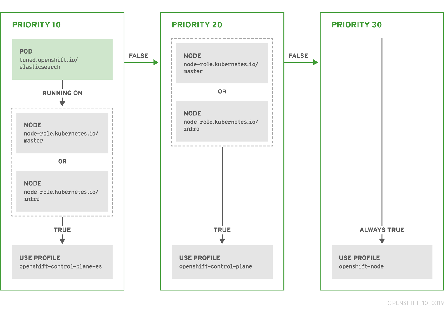
Example: machine config pool based matching
apiVersion: tuned.openshift.io/v1
kind: Tuned
metadata:
name: openshift-node-custom
  namespace: openshift-cluster-node-tuning-operator
spec:
  profile:
- data: |
[main]
summary=Custom OpenShift node profile with an additional kernel parameter
include=openshift-node
[bootloader]
cmdline_openshift_node_custom=+skew_tick=1
name: openshift-node-custom
recommend:
- machineConfigLabels:
machineconfiguration.openshift.io/role: "worker-custom"
priority: 20
profile: openshift-node-customTo minimize node reboots, label the target nodes with a label the machine config pool’s node selector will match, then create the Tuned CR above and finally create the custom machine config pool itself.
2.14.3. Default profiles set on a cluster
The following are the default profiles set on a cluster.
apiVersion: tuned.openshift.io/v1
kind: Tuned
metadata:
name: default
namespace: openshift-cluster-node-tuning-operator
spec:
profile:
- name: "openshift"
data: |
[main]
summary=Optimize systems running OpenShift (parent profile)
include=${f:virt_check:virtual-guest:throughput-performance}
[selinux]
avc_cache_threshold=8192
[net]
nf_conntrack_hashsize=131072
[sysctl]
net.ipv4.ip_forward=1
kernel.pid_max=>4194304
net.netfilter.nf_conntrack_max=1048576
net.ipv4.conf.all.arp_announce=2
net.ipv4.neigh.default.gc_thresh1=8192
net.ipv4.neigh.default.gc_thresh2=32768
net.ipv4.neigh.default.gc_thresh3=65536
net.ipv6.neigh.default.gc_thresh1=8192
net.ipv6.neigh.default.gc_thresh2=32768
net.ipv6.neigh.default.gc_thresh3=65536
vm.max_map_count=262144
[sysfs]
/sys/module/nvme_core/parameters/io_timeout=4294967295
/sys/module/nvme_core/parameters/max_retries=10
- name: "openshift-control-plane"
data: |
[main]
summary=Optimize systems running OpenShift control plane
include=openshift
[sysctl]
# ktune sysctl settings, maximizing i/o throughput
#
# Minimal preemption granularity for CPU-bound tasks:
# (default: 1 msec# (1 + ilog(ncpus)), units: nanoseconds)
kernel.sched_min_granularity_ns=10000000
# The total time the scheduler will consider a migrated process
# "cache hot" and thus less likely to be re-migrated
# (system default is 500000, i.e. 0.5 ms)
kernel.sched_migration_cost_ns=5000000
# SCHED_OTHER wake-up granularity.
#
# Preemption granularity when tasks wake up. Lower the value to
# improve wake-up latency and throughput for latency critical tasks.
kernel.sched_wakeup_granularity_ns=4000000
- name: "openshift-node"
data: |
[main]
summary=Optimize systems running OpenShift nodes
include=openshift
[sysctl]
net.ipv4.tcp_fastopen=3
fs.inotify.max_user_watches=65536
fs.inotify.max_user_instances=8192
recommend:
- profile: "openshift-control-plane"
priority: 30
match:
- label: "node-role.kubernetes.io/master"
- label: "node-role.kubernetes.io/infra"
- profile: "openshift-node"
priority: 402.14.4. Supported Tuned daemon plug-ins
Excluding the [main] section, the following Tuned plug-ins are supported when using custom profiles defined in the profile: section of the Tuned CR:
- audio
- cpu
- disk
- eeepc_she
- modules
- mounts
- net
- scheduler
- scsi_host
- selinux
- sysctl
- sysfs
- usb
- video
- vm
There is some dynamic tuning functionality provided by some of these plug-ins that is not supported. The following Tuned plug-ins are currently not supported:
- bootloader
- script
- systemd
See Available Tuned Plug-ins and Getting Started with Tuned for more information.
2.15. Configuring the maximum number of pods per node
Two parameters control the maximum number of pods that can be scheduled to a node: podsPerCore and maxPods. If you use both options, the lower of the two limits the number of pods on a node.
For example, if podsPerCore is set to 10 on a node with 4 processor cores, the maximum number of pods allowed on the node will be 40.
Prerequisites
Obtain the label associated with the static
MachineConfigPoolCRD for the type of node you want to configure. Perform one of the following steps:View the machine config pool:
$ oc describe machineconfigpool <name>For example:
$ oc describe machineconfigpool workerExample output
apiVersion: machineconfiguration.openshift.io/v1
kind: MachineConfigPool
metadata:
  creationTimestamp: 2019-02-08T14:52:39Z
  generation: 1
  labels:
    custom-kubelet: small-pods
1 - 1
- If a label has been added it appears under
labels.
If the label is not present, add a key/value pair:
$ oc label machineconfigpool worker custom-kubelet=small-pods
Procedure
Create a custom resource (CR) for your configuration change.
Sample configuration for a
max-podsCRapiVersion: machineconfiguration.openshift.io/v1 kind: KubeletConfig metadata: name: set-max-pods1 spec: machineConfigPoolSelector: matchLabels: custom-kubelet: small-pods2 kubeletConfig: podsPerCore: 103 maxPods: 2504 NoteSetting
podsPerCoreto0disables this limit.In the above example, the default value for
podsPerCoreis10and the default value formaxPodsis250. This means that unless the node has 25 cores or more, by default,podsPerCorewill be the limiting factor.List the
MachineConfigPoolCRDs to see if the change is applied. TheUPDATINGcolumn reportsTrueif the change is picked up by the Machine Config Controller:$ oc get machineconfigpoolsExample output
NAME     CONFIG                        UPDATED   UPDATING   DEGRADED
master   master-9cc2c72f205e103bb534   False     False      False
worker   worker-8cecd1236b33ee3f8a5e   False     True       False
Once the change is complete, the
UPDATEDcolumn reportsTrue.$ oc get machineconfigpoolsExample output
NAME     CONFIG                        UPDATED   UPDATING   DEGRADED
master   master-9cc2c72f205e103bb534   False     True       False
worker   worker-8cecd1236b33ee3f8a5e   True      False      False
Chapter 3. Post-installation network configuration
After installing OpenShift Container Platform, you can further expand and customize your network to your requirements.
3.1. Configuring network policy with OpenShift SDN
Understand and work with network policy.
3.1.1. About network policy
In a cluster using a Kubernetes Container Network Interface (CNI) plug-in that supports Kubernetes network policy, network isolation is controlled entirely by NetworkPolicy objects. In OpenShift Container Platform 4.5, OpenShift SDN supports using network policy in its default network isolation mode.
When using the OpenShift SDN cluster network provider, the following limitations apply regarding network policies:
-
Egress network policy as specified by the
egressfield is not supported. -
IPBlock is supported by network policy, but without support for
exceptclauses. If you create a policy with an IPBlock section that includes anexceptclause, the SDN pods log warnings and the entire IPBlock section of that policy is ignored.
Network policy does not apply to the host network namespace. Pods with host networking enabled are unaffected by network policy rules.
By default, all pods in a project are accessible from other pods and network endpoints. To isolate one or more pods in a project, you can create NetworkPolicy objects in that project to indicate the allowed incoming connections. Project administrators can create and delete NetworkPolicy objects within their own project.
If a pod is matched by selectors in one or more NetworkPolicy objects, then the pod will accept only connections that are allowed by at least one of those NetworkPolicy objects. A pod that is not selected by any NetworkPolicy objects is fully accessible.
The following example NetworkPolicy objects demonstrate supporting different scenarios:
Deny all traffic:
To make a project deny by default, add a
NetworkPolicyobject that matches all pods but accepts no traffic:kind: NetworkPolicy apiVersion: networking.k8s.io/v1 metadata: name: deny-by-default spec: podSelector: ingress: []Only allow connections from the OpenShift Container Platform Ingress Controller:
To make a project allow only connections from the OpenShift Container Platform Ingress Controller, add the following
NetworkPolicyobject.ImportantFor the OVN-Kubernetes network provider plug-in, when the Ingress Controller is configured to use the
HostNetworkendpoint publishing strategy, there is no supported way to apply network policy so that ingress traffic is allowed and all other traffic is denied.apiVersion: networking.k8s.io/v1 kind: NetworkPolicy metadata: name: allow-from-openshift-ingress spec: ingress: - from: - namespaceSelector: matchLabels: network.openshift.io/policy-group: ingress podSelector: {} policyTypes: - IngressIf the Ingress Controller is configured with
endpointPublishingStrategy: HostNetwork, then the Ingress Controller pod runs on the host network. When running on the host network, the traffic from the Ingress Controller is assigned thenetid:0Virtual Network ID (VNID). Thenetidfor the namespace that is associated with the Ingress Operator is different, so thematchLabelin theallow-from-openshift-ingressnetwork policy does not match traffic from thedefaultIngress Controller. With OpenShift SDN, thedefaultnamespace is assigned thenetid:0VNID and you can allow traffic from thedefaultIngress Controller by labeling yourdefaultnamespace withnetwork.openshift.io/policy-group: ingress.Only accept connections from pods within a project:
To make pods accept connections from other pods in the same project, but reject all other connections from pods in other projects, add the following
NetworkPolicyobject:kind: NetworkPolicy apiVersion: networking.k8s.io/v1 metadata: name: allow-same-namespace spec: podSelector: ingress: - from: - podSelector: {}Only allow HTTP and HTTPS traffic based on pod labels:
To enable only HTTP and HTTPS access to the pods with a specific label (
role=frontendin following example), add aNetworkPolicyobject similar to the following:kind: NetworkPolicy apiVersion: networking.k8s.io/v1 metadata: name: allow-http-and-https spec: podSelector: matchLabels: role: frontend ingress: - ports: - protocol: TCP port: 80 - protocol: TCP port: 443Accept connections by using both namespace and pod selectors:
To match network traffic by combining namespace and pod selectors, you can use a
NetworkPolicyobject similar to the following:kind: NetworkPolicy apiVersion: networking.k8s.io/v1 metadata: name: allow-pod-and-namespace-both spec: podSelector: matchLabels: name: test-pods ingress: - from: - namespaceSelector: matchLabels: project: project_name podSelector: matchLabels: name: test-pods
NetworkPolicy objects are additive, which means you can combine multiple NetworkPolicy objects together to satisfy complex network requirements.
For example, for the NetworkPolicy objects defined in previous samples, you can define both allow-same-namespace and allow-http-and-https policies within the same project. Thus allowing the pods with the label role=frontend, to accept any connection allowed by each policy. That is, connections on any port from pods in the same namespace, and connections on ports 80 and 443 from pods in any namespace.
3.1.2. Example NetworkPolicy object
The following annotates an example NetworkPolicy object:
kind: NetworkPolicy
apiVersion: networking.k8s.io/v1
metadata:
name: allow-27107
spec:
podSelector:
matchLabels:
app: mongodb
ingress:
- from:
- podSelector:
matchLabels:
app: app
ports:
- protocol: TCP
port: 27017- 1
- The
nameof the NetworkPolicy object. - 2
- A selector describing the pods the policy applies to. The policy object can only select pods in the project that the NetworkPolicy object is defined.
- 3
- A selector matching the pods that the policy object allows ingress traffic from. The selector will match pods in any project.
- 4
- A list of one or more destination ports to accept traffic on.
3.1.3. Creating a network policy
To define granular rules describing ingress or egress network traffic allowed for namespaces in your cluster, you can create a network policy.
If you log in with a user with the cluster-admin role, then you can create a network policy in any namespace in the cluster.
Prerequisites
-
Your cluster uses a cluster network provider that supports
NetworkPolicyobjects, such as the OpenShift SDN network provider withmode: NetworkPolicyset. This mode is the default for OpenShift SDN. -
You installed the OpenShift CLI (
oc). -
You are logged in to the cluster with a user with
adminprivileges. - You are working in the namespace that the network policy applies to.
Procedure
Create a policy rule:
Create a
<policy_name>.yamlfile:$ touch <policy_name>.yamlwhere:
<policy_name>- Specifies the network policy file name.
Define a network policy in the file that you just created, such as in the following examples:
Deny ingress from all pods in all namespaces
kind: NetworkPolicy apiVersion: networking.k8s.io/v1 metadata: name: deny-by-default spec: podSelector: ingress: []Allow ingress from all pods in the same namespace
kind: NetworkPolicy
apiVersion: networking.k8s.io/v1
metadata:
  name: allow-same-namespace
spec:
  podSelector:
  ingress:
  - from:
    - podSelector: {}
To create the network policy object, enter the following command:
$ oc apply -f <policy_name>.yaml -n <namespace>where:
<policy_name>- Specifies the network policy file name.
<namespace>- Optional: Specifies the namespace if the object is defined in a different namespace than the current namespace.
Example output
networkpolicy "default-deny" created
3.1.4. Deleting a network policy
You can delete a network policy in a namespace.
If you log in with a user with the cluster-admin role, then you can delete any network policy in the cluster.
Prerequisites
-
Your cluster uses a cluster network provider that supports
NetworkPolicyobjects, such as the OpenShift SDN network provider withmode: NetworkPolicyset. This mode is the default for OpenShift SDN. -
You installed the OpenShift CLI (
oc). -
You are logged in to the cluster with a user with
adminprivileges. - You are working in the namespace where the network policy exists.
Procedure
To delete a
NetworkPolicyobject, enter the following command:$ oc delete networkpolicy <policy_name> -n <namespace>where:
<policy_name>- Specifies the name of the network policy.
<namespace>- Optional: Specifies the namespace if the object is defined in a different namespace than the current namespace.
Example output
networkpolicy.networking.k8s.io/allow-same-namespace deleted
3.1.5. Viewing network policies
You can examine the network policies in a namespace.
If you log in with a user with the cluster-admin role, then you can view any network policy in the cluster.
Prerequisites
-
You installed the OpenShift CLI (
oc). -
You are logged in to the cluster with a user with
adminprivileges. - You are working in the namespace where the network policy exists.
Procedure
List network policies in a namespace:
To view
NetworkPolicyobjects defined in a namespace, enter the following command:$ oc get networkpolicyOptional: To examine a specific network policy, enter the following command:
$ oc describe networkpolicy <policy_name> -n <namespace>where:
<policy_name>- Specifies the name of the network policy to inspect.
<namespace>- Optional: Specifies the namespace if the object is defined in a different namespace than the current namespace.
For example:
$ oc describe networkpolicy allow-same-namespaceOutput for
oc describecommandName: allow-same-namespace Namespace: ns1 Created on: 2021-05-24 22:28:56 -0400 EDT Labels: <none> Annotations: <none> Spec: PodSelector: <none> (Allowing the specific traffic to all pods in this namespace) Allowing ingress traffic: To Port: <any> (traffic allowed to all ports) From: PodSelector: <none> Not affecting egress traffic Policy Types: Ingress
3.1.6. Configuring multitenant isolation by using network policy
You can configure your project to isolate it from pods and services in other project namespaces.
Prerequisites
-
Your cluster uses a cluster network provider that supports
NetworkPolicyobjects, such as the OpenShift SDN network provider withmode: NetworkPolicyset. This mode is the default for OpenShift SDN. -
You installed the OpenShift CLI (
oc). -
You are logged in to the cluster with a user with
adminprivileges.
Procedure
Create the following
NetworkPolicyobjects:A policy named
allow-from-openshift-ingress.ImportantFor the OVN-Kubernetes network provider plug-in, when the Ingress Controller is configured to use the
HostNetworkendpoint publishing strategy, there is no supported way to apply network policy so that ingress traffic is allowed and all other traffic is denied.$ cat << EOF| oc create -f - apiVersion: networking.k8s.io/v1 kind: NetworkPolicy metadata: name: allow-from-openshift-ingress spec: ingress: - from: - namespaceSelector: matchLabels: network.openshift.io/policy-group: ingress podSelector: {} policyTypes: - Ingress EOFA policy named
allow-from-openshift-monitoring:$ cat << EOF| oc create -f - apiVersion: networking.k8s.io/v1 kind: NetworkPolicy metadata: name: allow-from-openshift-monitoring spec: ingress: - from: - namespaceSelector: matchLabels: network.openshift.io/policy-group: monitoring podSelector: {} policyTypes: - Ingress EOFA policy named
allow-same-namespace:$ cat << EOF| oc create -f - kind: NetworkPolicy apiVersion: networking.k8s.io/v1 metadata: name: allow-same-namespace spec: podSelector: ingress: - from: - podSelector: {} EOF
If the
defaultIngress Controller configuration has thespec.endpointPublishingStrategy: HostNetworkvalue set, you must apply a label to thedefaultOpenShift Container Platform namespace to allow network traffic between the Ingress Controller and the project:Determine if your
defaultIngress Controller uses theHostNetworkendpoint publishing strategy:$ oc get --namespace openshift-ingress-operator ingresscontrollers/default \ --output jsonpath='{.status.endpointPublishingStrategy.type}'If the previous command reports the endpoint publishing strategy as
HostNetwork, set a label on thedefaultnamespace:$ oc label namespace default 'network.openshift.io/policy-group=ingress'
Confirm that the
NetworkPolicyobject exists in your current project by running the following command:$ oc get networkpolicy <policy-name> -o yamlIn the following example, the
allow-from-openshift-ingressNetworkPolicyobject is displayed:$ oc get -n project1 networkpolicy allow-from-openshift-ingress -o yamlExample output
apiVersion: networking.k8s.io/v1 kind: NetworkPolicy metadata: name: allow-from-openshift-ingress namespace: project1 spec: ingress: - from: - namespaceSelector: matchLabels: network.openshift.io/policy-group: ingress podSelector: {} policyTypes: - Ingress
3.1.7. Creating default network policies for a new project
As a cluster administrator, you can modify the new project template to automatically include NetworkPolicy objects when you create a new project.
3.1.8. Modifying the template for new projects
As a cluster administrator, you can modify the default project template so that new projects are created using your custom requirements.
To create your own custom project template:
Procedure
-
Log in as a user with
cluster-adminprivileges. Generate the default project template:
$ oc adm create-bootstrap-project-template -o yaml > template.yaml-
Use a text editor to modify the generated
template.yamlfile by adding objects or modifying existing objects. The project template must be created in the
openshift-confignamespace. Load your modified template:$ oc create -f template.yaml -n openshift-configEdit the project configuration resource using the web console or CLI.
Using the web console:
- Navigate to the Administration → Cluster Settings page.
- Click Global Configuration to view all configuration resources.
- Find the entry for Project and click Edit YAML.
Using the CLI:
Edit the
project.config.openshift.io/clusterresource:$ oc edit project.config.openshift.io/cluster
Update the
specsection to include theprojectRequestTemplateandnameparameters, and set the name of your uploaded project template. The default name isproject-request.Project configuration resource with custom project template
apiVersion: config.openshift.io/v1 kind: Project metadata: ... spec: projectRequestTemplate: name: <template_name>- After you save your changes, create a new project to verify that your changes were successfully applied.
3.1.8.1. Adding network policies to the new project template
As a cluster administrator, you can add network policies to the default template for new projects. OpenShift Container Platform will automatically create all the NetworkPolicy objects specified in the template in the project.
Prerequisites
-
Your cluster uses a default CNI network provider that supports
NetworkPolicyobjects, such as the OpenShift SDN network provider withmode: NetworkPolicyset. This mode is the default for OpenShift SDN. -
You installed the OpenShift CLI (
oc). -
You must log in to the cluster with a user with
cluster-adminprivileges. - You must have created a custom default project template for new projects.
Procedure
Edit the default template for a new project by running the following command:
$ oc edit template <project_template> -n openshift-configReplace
<project_template>with the name of the default template that you configured for your cluster. The default template name isproject-request.In the template, add each
NetworkPolicyobject as an element to theobjectsparameter. Theobjectsparameter accepts a collection of one or more objects.In the following example, the
objectsparameter collection includes severalNetworkPolicyobjects:objects: - apiVersion: networking.k8s.io/v1 kind: NetworkPolicy metadata: name: allow-from-same-namespace spec: podSelector: ingress: - from: - podSelector: {} - apiVersion: networking.k8s.io/v1 kind: NetworkPolicy metadata: name: allow-from-openshift-ingress spec: ingress: - from: - namespaceSelector: matchLabels: network.openshift.io/policy-group: ingress podSelector: {} policyTypes: - Ingress ...Optional: Create a new project to confirm that your network policy objects are created successfully by running the following commands:
Create a new project:
$ oc new-project <project>1 - 1
- Replace
<project>with the name for the project you are creating.
Confirm that the network policy objects in the new project template exist in the new project:
$ oc get networkpolicy NAME POD-SELECTOR AGE allow-from-openshift-ingress <none> 7s allow-from-same-namespace <none> 7s
3.2. Setting DNS to private
After you deploy a cluster, you can modify its DNS to use only a private zone.
Procedure
Review the
DNScustom resource for your cluster:$ oc get dnses.config.openshift.io/cluster -o yamlExample output
apiVersion: config.openshift.io/v1 kind: DNS metadata: creationTimestamp: "2019-10-25T18:27:09Z" generation: 2 name: cluster resourceVersion: "37966" selfLink: /apis/config.openshift.io/v1/dnses/cluster uid: 0e714746-f755-11f9-9cb1-02ff55d8f976 spec: baseDomain: <base_domain> privateZone: tags: Name: <infrastructureID>-int kubernetes.io/cluster/<infrastructureID>: owned publicZone: id: Z2XXXXXXXXXXA4 status: {}Note that the
specsection contains both a private and a public zone.Patch the
DNScustom resource to remove the public zone:$ oc patch dnses.config.openshift.io/cluster --type=merge --patch='{"spec": {"publicZone": null}}' dns.config.openshift.io/cluster patchedBecause the Ingress Controller consults the
DNSdefinition when it createsIngressobjects, when you create or modifyIngressobjects, only private records are created.ImportantDNS records for the existing Ingress objects are not modified when you remove the public zone.
Optional: Review the
DNScustom resource for your cluster and confirm that the public zone was removed:$ oc get dnses.config.openshift.io/cluster -o yamlExample output
apiVersion: config.openshift.io/v1 kind: DNS metadata: creationTimestamp: "2019-10-25T18:27:09Z" generation: 2 name: cluster resourceVersion: "37966" selfLink: /apis/config.openshift.io/v1/dnses/cluster uid: 0e714746-f755-11f9-9cb1-02ff55d8f976 spec: baseDomain: <base_domain> privateZone: tags: Name: <infrastructureID>-int kubernetes.io/cluster/<infrastructureID>-wfpg4: owned status: {}
3.3. Enabling the cluster-wide proxy
The Proxy object is used to manage the cluster-wide egress proxy. When a cluster is installed or upgraded without the proxy configured, a Proxy object is still generated but it will have a nil spec. For example:
apiVersion: config.openshift.io/v1
kind: Proxy
metadata:
name: cluster
spec:
trustedCA:
name: ""
status:
A cluster administrator can configure the proxy for OpenShift Container Platform by modifying this cluster Proxy object.
Only the Proxy object named cluster is supported, and no additional proxies can be created.
Prerequisites
- Cluster administrator permissions
-
OpenShift Container Platform
ocCLI tool installed
Procedure
Create a ConfigMap that contains any additional CA certificates required for proxying HTTPS connections.
NoteYou can skip this step if the proxy’s identity certificate is signed by an authority from the RHCOS trust bundle.
Create a file called
user-ca-bundle.yamlwith the following contents, and provide the values of your PEM-encoded certificates:apiVersion: v1 data: ca-bundle.crt: |1 <MY_PEM_ENCODED_CERTS>2 kind: ConfigMap metadata: name: user-ca-bundle3 namespace: openshift-config4 Create the ConfigMap from this file:
$ oc create -f user-ca-bundle.yaml
Use the
oc editcommand to modify the Proxy object:$ oc edit proxy/clusterConfigure the necessary fields for the proxy:
apiVersion: config.openshift.io/v1 kind: Proxy metadata: name: cluster spec: httpProxy: http://<username>:<pswd>@<ip>:<port>1 httpsProxy: http://<username>:<pswd>@<ip>:<port>2 noProxy: example.com3 readinessEndpoints: - http://www.google.com4 - https://www.google.com trustedCA: name: user-ca-bundle5 - 1
- A proxy URL to use for creating HTTP connections outside the cluster. The URL scheme must be
http. - 2
- A proxy URL to use for creating HTTPS connections outside the cluster. If this is not specified, then
httpProxyis used for both HTTP and HTTPS connections. - 3
- A comma-separated list of destination domain names, domains, IP addresses or other network CIDRs to exclude proxying.
Preface a domain with
.to match subdomains only. For example,.y.commatchesx.y.com, but noty.com. Use*to bypass proxy for all destinations. If you scale up workers that are not included in the network defined by thenetworking.machineNetwork[].cidrfield from the installation configuration, you must add them to this list to prevent connection issues.This field is ignored if neither the
httpProxyorhttpsProxyfields are set. - 4
- One or more URLs external to the cluster to use to perform a readiness check before writing the
httpProxyandhttpsProxyvalues to status. - 5
- A reference to the ConfigMap in the
openshift-confignamespace that contains additional CA certificates required for proxying HTTPS connections. Note that the ConfigMap must already exist before referencing it here. This field is required unless the proxy’s identity certificate is signed by an authority from the RHCOS trust bundle.
- Save the file to apply the changes.
The URL scheme must be http. The https scheme is currently not supported.
3.4. Cluster Network Operator configuration
The configuration for the cluster network is specified as part of the Cluster Network Operator (CNO) configuration and stored in a CR object that is named cluster. The CR specifies the parameters for the Network API in the operator.openshift.io API group.
After cluster installation, you cannot modify the configuration for the cluster network provider.
3.5. Configuring ingress cluster traffic
OpenShift Container Platform provides the following methods for communicating from outside the cluster with services running in the cluster:
- If you have HTTP/HTTPS, use an Ingress Controller.
- If you have a TLS-encrypted protocol other than HTTPS, such as TLS with the SNI header, use an Ingress Controller.
- Otherwise, use a load balancer, an external IP, or a node port.
| Method | Purpose |
|---|---|
| Allows access to HTTP/HTTPS traffic and TLS-encrypted protocols other than HTTPS, such as TLS with the SNI header. | |
| Automatically assign an external IP by using a load balancer service | Allows traffic to non-standard ports through an IP address assigned from a pool. |
| Allows traffic to non-standard ports through a specific IP address. | |
| Expose a service on all nodes in the cluster. |
3.6. Red Hat OpenShift Service Mesh supported configurations
The following are the only supported configurations for the Red Hat OpenShift Service Mesh:
- Red Hat OpenShift Container Platform version 4.x.
OpenShift Online and OpenShift Dedicated are not supported for Red Hat OpenShift Service Mesh.
- The deployment must be contained to a single OpenShift Container Platform cluster that is not federated.
- This release of Red Hat OpenShift Service Mesh is only available on OpenShift Container Platform x86_64.
- This release only supports configurations where all Service Mesh components are contained in the OpenShift cluster in which it operates. It does not support management of microservices that reside outside of the cluster, or in a multi-cluster scenario.
- This release only supports configurations that do not integrate external services such as virtual machines.
3.6.1. Supported configurations for Kiali on Red Hat OpenShift Service Mesh
- The Kiali observability console is only supported on the two most recent releases of the Chrome, Edge, Firefox, or Safari browsers.
3.6.2. Supported Mixer adapters
This release only supports the following Mixer adapter:
- 3scale Istio Adapter
3.6.3. Red Hat OpenShift Service Mesh installation activities
To install the Red Hat OpenShift Service Mesh Operator, you must first install these Operators:
- Elasticsearch - Based on the open source Elasticsearch project that enables you to configure and manage an Elasticsearch cluster for tracing and logging with Jaeger.
- Jaeger - based on the open source Jaeger project, lets you perform tracing to monitor and troubleshoot transactions in complex distributed systems.
- Kiali - based on the open source Kiali project, provides observability for your service mesh. By using Kiali you can view configurations, monitor traffic, and view and analyze traces in a single console.
After you install the Elasticsearch, Jaeger, and Kiali Operators, then you install the Red Hat OpenShift Service Mesh Operator. The Service Mesh Operator defines and monitors the ServiceMeshControlPlane resources that manage the deployment, updating, and deletion of the Service Mesh components.
- Red Hat OpenShift Service Mesh - based on the open source Istio project, lets you connect, secure, control, and observe the microservices that make up your applications.
Next steps
- Install Red Hat OpenShift Service Mesh in your OpenShift Container Platform environment.
3.7. Optimizing routing
The OpenShift Container Platform HAProxy router scales to optimize performance.
3.7.1. Baseline Ingress Controller (router) performance
The OpenShift Container Platform Ingress Controller, or router, is the Ingress point for all external traffic destined for OpenShift Container Platform services.
When evaluating a single HAProxy router performance in terms of HTTP requests handled per second, the performance varies depending on many factors. In particular:
- HTTP keep-alive/close mode
- Route type
- TLS session resumption client support
- Number of concurrent connections per target route
- Number of target routes
- Back end server page size
- Underlying infrastructure (network/SDN solution, CPU, and so on)
While performance in your specific environment will vary, Red Hat lab tests on a public cloud instance of size 4 vCPU/16GB RAM. A single HAProxy router handling 100 routes terminated by backends serving 1kB static pages is able to handle the following number of transactions per second.
In HTTP keep-alive mode scenarios:
| Encryption | LoadBalancerService | HostNetwork |
|---|---|---|
| none | 21515 | 29622 |
| edge | 16743 | 22913 |
| passthrough | 36786 | 53295 |
| re-encrypt | 21583 | 25198 |
In HTTP close (no keep-alive) scenarios:
| Encryption | LoadBalancerService | HostNetwork |
|---|---|---|
| none | 5719 | 8273 |
| edge | 2729 | 4069 |
| passthrough | 4121 | 5344 |
| re-encrypt | 2320 | 2941 |
Default Ingress Controller configuration with ROUTER_THREADS=4 was used and two different endpoint publishing strategies (LoadBalancerService/HostNetwork) were tested. TLS session resumption was used for encrypted routes. With HTTP keep-alive, a single HAProxy router is capable of saturating 1 Gbit NIC at page sizes as small as 8 kB.
When running on bare metal with modern processors, you can expect roughly twice the performance of the public cloud instance above. This overhead is introduced by the virtualization layer in place on public clouds and holds mostly true for private cloud-based virtualization as well. The following table is a guide to how many applications to use behind the router:
| Number of applications | Application type |
|---|---|
| 5-10 | static file/web server or caching proxy |
| 100-1000 | applications generating dynamic content |
In general, HAProxy can support routes for 5 to 1000 applications, depending on the technology in use. Ingress Controller performance might be limited by the capabilities and performance of the applications behind it, such as language or static versus dynamic content.
Ingress, or router, sharding should be used to serve more routes towards applications and help horizontally scale the routing tier.
3.7.2. Ingress Controller (router) performance optimizations
OpenShift Container Platform no longer supports modifying Ingress Controller deployments by setting environment variables such as ROUTER_THREADS, ROUTER_DEFAULT_TUNNEL_TIMEOUT, ROUTER_DEFAULT_CLIENT_TIMEOUT, ROUTER_DEFAULT_SERVER_TIMEOUT, and RELOAD_INTERVAL.
You can modify the Ingress Controller deployment, but if the Ingress Operator is enabled, the configuration is overwritten.
Chapter 4. Post-installation storage configuration
After installing OpenShift Container Platform, you can further expand and customize your cluster to your requirements, including storage configuration.
4.1. Dynamic provisioning
4.1.1. About dynamic provisioning
The StorageClass resource object describes and classifies storage that can be requested, as well as provides a means for passing parameters for dynamically provisioned storage on demand. StorageClass objects can also serve as a management mechanism for controlling different levels of storage and access to the storage. Cluster Administrators (cluster-admin) or Storage Administrators (storage-admin) define and create the StorageClass objects that users can request without needing any detailed knowledge about the underlying storage volume sources.
The OpenShift Container Platform persistent volume framework enables this functionality and allows administrators to provision a cluster with persistent storage. The framework also gives users a way to request those resources without having any knowledge of the underlying infrastructure.
Many storage types are available for use as persistent volumes in OpenShift Container Platform. While all of them can be statically provisioned by an administrator, some types of storage are created dynamically using the built-in provider and plug-in APIs.
4.1.2. Available dynamic provisioning plug-ins
OpenShift Container Platform provides the following provisioner plug-ins, which have generic implementations for dynamic provisioning that use the cluster’s configured provider’s API to create new storage resources:
| Storage type | Provisioner plug-in name | Notes |
|---|---|---|
| Red Hat OpenStack Platform (RHOSP) Cinder |
| |
| RHOSP Manila Container Storage Interface (CSI) |
| Once installed, the OpenStack Manila CSI Driver Operator and ManilaDriver automatically create the required storage classes for all available Manila share types needed for dynamic provisioning. |
| AWS Elastic Block Store (EBS) |
|
For dynamic provisioning when using multiple clusters in different zones, tag each node with |
| Azure Disk |
| |
| Azure File |
|
The |
| GCE Persistent Disk (gcePD) |
| In multi-zone configurations, it is advisable to run one OpenShift Container Platform cluster per GCE project to avoid PVs from being created in zones where no node in the current cluster exists. |
|
|
Any chosen provisioner plug-in also requires configuration for the relevant cloud, host, or third-party provider as per the relevant documentation.
4.2. Defining a storage class
StorageClass objects are currently a globally scoped object and must be created by cluster-admin or storage-admin users.
The Cluster Storage Operator might install a default storage class depending on the platform in use. This storage class is owned and controlled by the operator. It cannot be deleted or modified beyond defining annotations and labels. If different behavior is desired, you must define a custom storage class.
The following sections describe the basic definition for a StorageClass object and specific examples for each of the supported plug-in types.
4.2.1. Basic StorageClass object definition
The following resource shows the parameters and default values that you use to configure a storage class. This example uses the AWS ElasticBlockStore (EBS) object definition.
Sample StorageClass definition
kind: StorageClass
apiVersion: storage.k8s.io/v1
metadata:
name: gp2
annotations:
storageclass.kubernetes.io/is-default-class: 'true'
...
provisioner: kubernetes.io/aws-ebs
parameters:
type: gp2
...- 1
- (required) The API object type.
- 2
- (required) The current apiVersion.
- 3
- (required) The name of the storage class.
- 4
- (optional) Annotations for the storage class.
- 5
- (required) The type of provisioner associated with this storage class.
- 6
- (optional) The parameters required for the specific provisioner, this will change from plug-in to plug-in.
4.2.2. Storage class annotations
To set a storage class as the cluster-wide default, add the following annotation to your storage class metadata:
storageclass.kubernetes.io/is-default-class: "true"For example:
apiVersion: storage.k8s.io/v1
kind: StorageClass
metadata:
annotations:
storageclass.kubernetes.io/is-default-class: "true"
...This enables any persistent volume claim (PVC) that does not specify a specific storage class to automatically be provisioned through the default storage class.
The beta annotation storageclass.beta.kubernetes.io/is-default-class is still working; however, it will be removed in a future release.
To set a storage class description, add the following annotation to your storage class metadata:
kubernetes.io/description: My Storage Class DescriptionFor example:
apiVersion: storage.k8s.io/v1
kind: StorageClass
metadata:
annotations:
kubernetes.io/description: My Storage Class Description
...4.2.3. RHOSP Cinder object definition
cinder-storageclass.yaml
kind: StorageClass
apiVersion: storage.k8s.io/v1
metadata:
name: gold
provisioner: kubernetes.io/cinder
parameters:
type: fast
availability: nova
fsType: ext4 - 1
- Volume type created in Cinder. Default is empty.
- 2
- Availability Zone. If not specified, volumes are generally round-robined across all active zones where the OpenShift Container Platform cluster has a node.
- 3
- File system that is created on dynamically provisioned volumes. This value is copied to the
fsTypefield of dynamically provisioned persistent volumes and the file system is created when the volume is mounted for the first time. The default value isext4.
4.2.4. AWS Elastic Block Store (EBS) object definition
aws-ebs-storageclass.yaml
kind: StorageClass
apiVersion: storage.k8s.io/v1
metadata:
name: slow
provisioner: kubernetes.io/aws-ebs
parameters:
type: io1
iopsPerGB: "10"
encrypted: "true"
kmsKeyId: keyvalue
fsType: ext4 - 1
- (required) Select from
io1,gp2,sc1,st1. The default isgp2. See the AWS documentation for valid Amazon Resource Name (ARN) values. - 2
- (optional) Only for io1 volumes. I/O operations per second per GiB. The AWS volume plug-in multiplies this with the size of the requested volume to compute IOPS of the volume. The value cap is 20,000 IOPS, which is the maximum supported by AWS. See the AWS documentation for further details.
- 3
- (optional) Denotes whether to encrypt the EBS volume. Valid values are
trueorfalse. - 4
- (optional) The full ARN of the key to use when encrypting the volume. If none is supplied, but
encyptedis set totrue, then AWS generates a key. See the AWS documentation for a valid ARN value. - 5
- (optional) File system that is created on dynamically provisioned volumes. This value is copied to the
fsTypefield of dynamically provisioned persistent volumes and the file system is created when the volume is mounted for the first time. The default value isext4.
4.2.5. Azure Disk object definition
azure-advanced-disk-storageclass.yaml
apiVersion: storage.k8s.io/v1
kind: StorageClass
metadata:
name: managed-premium
annotations:
storageclass.kubernetes.io/is-default-class: "true"
provisioner: kubernetes.io/azure-disk
volumeBindingMode: WaitForFirstConsumer
allowVolumeExpansion: true
parameters:
kind: Managed
storageaccounttype: Premium_LRS
reclaimPolicy: Delete- 1
- Using
WaitForFirstConsumeris strongly recommended. This provisions the volume while allowing enough storage to schedule the pod on a free worker node from an available zone. - 2
- Possible values are
Shared(default),Managed, andDedicated.ImportantRed Hat only supports the use of
kind: Managedin the storage class.With
SharedandDedicated, Azure creates unmanaged disks, while OpenShift Container Platform creates a managed disk for machine OS (root) disks. But because Azure Disk does not allow the use of both managed and unmanaged disks on a node, unmanaged disks created withSharedorDedicatedcannot be attached to OpenShift Container Platform nodes. - 3
- Azure storage account SKU tier. Default is empty. Note that Premium VMs can attach both
Standard_LRSandPremium_LRSdisks, Standard VMs can only attachStandard_LRSdisks, Managed VMs can only attach managed disks, and unmanaged VMs can only attach unmanaged disks.-
If
kindis set toShared, Azure creates all unmanaged disks in a few shared storage accounts in the same resource group as the cluster. -
If
kindis set toManaged, Azure creates new managed disks. If
kindis set toDedicatedand astorageAccountis specified, Azure uses the specified storage account for the new unmanaged disk in the same resource group as the cluster. For this to work:- The specified storage account must be in the same region.
- Azure Cloud Provider must have write access to the storage account.
-
If
kindis set toDedicatedand astorageAccountis not specified, Azure creates a new dedicated storage account for the new unmanaged disk in the same resource group as the cluster.
-
If
4.2.6. Azure File object definition
The Azure File storage class uses secrets to store the Azure storage account name and the storage account key that are required to create an Azure Files share. These permissions are created as part of the following procedure.
Procedure
Define a
ClusterRoleobject that allows access to create and view secrets:apiVersion: rbac.authorization.k8s.io/v1 kind: ClusterRole metadata: # name: system:azure-cloud-provider name: <persistent-volume-binder-role>1 rules: - apiGroups: [''] resources: ['secrets'] verbs: ['get','create']- 1
- The name of the cluster role to view and create secrets.
Add the cluster role to the service account:
$ oc adm policy add-cluster-role-to-user <persistent-volume-binder-role>Example output
system:serviceaccount:kube-system:persistent-volume-binderCreate the Azure File
StorageClassobject:kind: StorageClass apiVersion: storage.k8s.io/v1 metadata: name: <azure-file>1 provisioner: kubernetes.io/azure-file parameters: location: eastus2 skuName: Standard_LRS3 storageAccount: <storage-account>4 reclaimPolicy: Delete volumeBindingMode: Immediate- 1
- Name of the storage class. The persistent volume claim uses this storage class for provisioning the associated persistent volumes.
- 2
- Location of the Azure storage account, such as
eastus. Default is empty, meaning that a new Azure storage account will be created in the OpenShift Container Platform cluster’s location. - 3
- SKU tier of the Azure storage account, such as
Standard_LRS. Default is empty, meaning that a new Azure storage account will be created with theStandard_LRSSKU. - 4
- Name of the Azure storage account. If a storage account is provided, then
skuNameandlocationare ignored. If no storage account is provided, then the storage class searches for any storage account that is associated with the resource group for any accounts that match the definedskuNameandlocation.
4.2.6.1. Considerations when using Azure File
The following file system features are not supported by the default Azure File storage class:
- Symlinks
- Hard links
- Extended attributes
- Sparse files
- Named pipes
Additionally, the owner user identifier (UID) of the Azure File mounted directory is different from the process UID of the container. The uid mount option can be specified in the StorageClass object to define a specific user identifier to use for the mounted directory.
The following StorageClass object demonstrates modifying the user and group identifier, along with enabling symlinks for the mounted directory.
kind: StorageClass
apiVersion: storage.k8s.io/v1
metadata:
name: azure-file
mountOptions:
- uid=1500
- gid=1500
- mfsymlinks
provisioner: kubernetes.io/azure-file
parameters:
location: eastus
skuName: Standard_LRS
reclaimPolicy: Delete
volumeBindingMode: Immediate4.2.7. GCE PersistentDisk (gcePD) object definition
gce-pd-storageclass.yaml
apiVersion: storage.k8s.io/v1
kind: StorageClass
metadata:
name: standard
annotations:
storageclass.kubernetes.io/is-default-class: "true"
provisioner: kubernetes.io/gce-pd
parameters:
type: pd-standard
replication-type: none
volumeBindingMode: WaitForFirstConsumer
allowVolumeExpansion: true
reclaimPolicy: Delete- 1
- Select either
pd-standardorpd-ssd. The default ispd-standard.
4.2.8. VMware vSphere object definition
vsphere-storageclass.yaml
kind: StorageClass
apiVersion: storage.k8s.io/v1
metadata:
name: slow
provisioner: kubernetes.io/vsphere-volume
parameters:
diskformat: thin - 1
- For more information about using VMware vSphere with OpenShift Container Platform, see the VMware vSphere documentation.
- 2
diskformat:thin,zeroedthickandeagerzeroedthickare all valid disk formats. See vSphere docs for additional details regarding the disk format types. The default value isthin.
4.3. Changing the default storage class
If you are using AWS, use the following process to change the default storage class. This process assumes you have two storage classes defined, gp2 and standard, and you want to change the default storage class from gp2 to standard.
List the storage class:
$ oc get storageclassExample output
NAME TYPE gp2 (default) kubernetes.io/aws-ebs1 standard kubernetes.io/aws-ebs- 1
(default)denotes the default storage class.
Change the value of the annotation
storageclass.kubernetes.io/is-default-classtofalsefor the default storage class:$ oc patch storageclass gp2 -p '{"metadata": {"annotations": {"storageclass.kubernetes.io/is-default-class": "false"}}}'Make another storage class the default by adding or modifying the annotation as
storageclass.kubernetes.io/is-default-class=true.$ oc patch storageclass standard -p '{"metadata": {"annotations": {"storageclass.kubernetes.io/is-default-class": "true"}}}'Verify the changes:
$ oc get storageclassExample output
NAME TYPE gp2 kubernetes.io/aws-ebs standard (default) kubernetes.io/aws-ebs
4.4. Optimizing storage
Optimizing storage helps to minimize storage use across all resources. By optimizing storage, administrators help ensure that existing storage resources are working in an efficient manner.
4.5. Available persistent storage options
Understand your persistent storage options so that you can optimize your OpenShift Container Platform environment.
| Storage type | Description | Examples |
|---|---|---|
| Block |
| AWS EBS and VMware vSphere support dynamic persistent volume (PV) provisioning natively in OpenShift Container Platform. |
| File |
| RHEL NFS, NetApp NFS [1], and Vendor NFS |
| Object |
| AWS S3 |
- NetApp NFS supports dynamic PV provisioning when using the Trident plug-in.
Currently, CNS is not supported in OpenShift Container Platform 4.5.
4.6. Recommended configurable storage technology
The following table summarizes the recommended and configurable storage technologies for the given OpenShift Container Platform cluster application.
| Storage type | ROX1 | RWX2 | Registry | Scaled registry | Metrics3 | Logging | Apps |
|---|---|---|---|---|---|---|---|
|
1
2 3 Prometheus is the underlying technology used for metrics. 4 This does not apply to physical disk, VM physical disk, VMDK, loopback over NFS, AWS EBS, and Azure Disk.
5 For metrics, using file storage with the 6 For logging, using any shared storage would be an anti-pattern. One volume per elasticsearch is required. 7 Object storage is not consumed through OpenShift Container Platform’s PVs or PVCs. Apps must integrate with the object storage REST API. | |||||||
| Block | Yes4 | No | Configurable | Not configurable | Recommended | Recommended | Recommended |
| File | Yes4 | Yes | Configurable | Configurable | Configurable5 | Configurable6 | Recommended |
| Object | Yes | Yes | Recommended | Recommended | Not configurable | Not configurable | Not configurable7 |
A scaled registry is an OpenShift Container Platform registry where two or more pod replicas are running.
4.6.1. Specific application storage recommendations
Testing shows issues with using the NFS server on Red Hat Enterprise Linux (RHEL) as storage backend for core services. This includes the OpenShift Container Registry and Quay, Prometheus for monitoring storage, and Elasticsearch for logging storage. Therefore, using RHEL NFS to back PVs used by core services is not recommended.
Other NFS implementations on the marketplace might not have these issues. Contact the individual NFS implementation vendor for more information on any testing that was possibly completed against these OpenShift Container Platform core components.
4.6.1.1. Registry
In a non-scaled/high-availability (HA) OpenShift Container Platform registry cluster deployment:
- The storage technology does not have to support RWX access mode.
- The storage technology must ensure read-after-write consistency.
- The preferred storage technology is object storage followed by block storage.
- File storage is not recommended for OpenShift Container Platform registry cluster deployment with production workloads.
4.6.1.2. Scaled registry
In a scaled/HA OpenShift Container Platform registry cluster deployment:
- The storage technology must support RWX access mode and must ensure read-after-write consistency.
- The preferred storage technology is object storage.
- Amazon Simple Storage Service (Amazon S3), Google Cloud Storage (GCS), Microsoft Azure Blob Storage, and OpenStack Swift are supported.
- Object storage should be S3 or Swift compliant.
- File storage is not recommended for a scaled/HA OpenShift Container Platform registry cluster deployment with production workloads.
- For non-cloud platforms, such as vSphere and bare metal installations, the only configurable technology is file storage.
- Block storage is not configurable.
4.6.1.3. Metrics
In an OpenShift Container Platform hosted metrics cluster deployment:
- The preferred storage technology is block storage.
- Object storage is not configurable.
It is not recommended to use file storage for a hosted metrics cluster deployment with production workloads.
4.6.1.4. Logging
In an OpenShift Container Platform hosted logging cluster deployment:
- The preferred storage technology is block storage.
- File storage is not recommended for a scaled/HA OpenShift Container Platform registry cluster deployment with production workloads.
- Object storage is not configurable.
Testing shows issues with using the NFS server on RHEL as storage backend for core services. This includes Elasticsearch for logging storage. Therefore, using RHEL NFS to back PVs used by core services is not recommended.
Other NFS implementations on the marketplace might not have these issues. Contact the individual NFS implementation vendor for more information on any testing that was possibly completed against these OpenShift Container Platform core components.
4.6.1.5. Applications
Application use cases vary from application to application, as described in the following examples:
- Storage technologies that support dynamic PV provisioning have low mount time latencies, and are not tied to nodes to support a healthy cluster.
- Application developers are responsible for knowing and understanding the storage requirements for their application, and how it works with the provided storage to ensure that issues do not occur when an application scales or interacts with the storage layer.
4.6.2. Other specific application storage recommendations
-
OpenShift Container Platform Internal
etcd: For the bestetcdreliability, the lowest consistent latency storage technology is preferable. -
It is highly recommended that you use
etcdwith storage that handles serial writes (fsync) quickly, such as NVMe or SSD. Ceph, NFS, and spinning disks are not recommended. - Red Hat OpenStack Platform (RHOSP) Cinder: RHOSP Cinder tends to be adept in ROX access mode use cases.
- Databases: Databases (RDBMSs, NoSQL DBs, etc.) tend to perform best with dedicated block storage.
4.7. Deploy Red Hat OpenShift Container Storage
Red Hat OpenShift Container Storage is a provider of agnostic persistent storage for OpenShift Container Platform supporting file, block, and object storage, either in-house or in hybrid clouds. As a Red Hat storage solution, Red Hat OpenShift Container Storage is completely integrated with OpenShift Container Platform for deployment, management, and monitoring.
| If you are looking for Red Hat OpenShift Container Storage information about… | See the following Red Hat OpenShift Container Storage documentation: |
|---|---|
| What’s new, known issues, notable bug fixes, and Technology Previews | |
| Supported workloads, layouts, hardware and software requirements, sizing and scaling recommendations | |
| Instructions on preparing to deploy when your environment is not directly connected to the internet | Preparing to deploy OpenShift Container Storage 4.5 in a disconnected environment |
| Instructions on deploying OpenShift Container Storage to use an external Red Hat Ceph Storage cluster | |
| Instructions on deploying OpenShift Container Storage to local storage on bare metal infrastructure | Deploying OpenShift Container Storage 4.5 using bare metal infrastructure |
| Instructions on deploying OpenShift Container Storage on Red Hat OpenShift Container Platform VMWare vSphere clusters | |
| Instructions on deploying OpenShift Container Storage using Amazon Web Services for local or cloud storage | Deploying OpenShift Container Storage 4.5 using Amazon Web Services |
| Instructions on deploying and managing OpenShift Container Storage on existing Red Hat OpenShift Container Platform Google Cloud clusters | Deploying and managing OpenShift Container Storage 4.5 using Google Cloud |
| Instructions on deploying and managing OpenShift Container Storage on existing Red Hat OpenShift Container Platform Azure clusters | Deploying and managing OpenShift Container Storage 4.5 using Microsoft Azure |
| Managing a Red Hat OpenShift Container Storage 4.5 cluster | |
| Monitoring a Red Hat OpenShift Container Storage 4.5 cluster | |
| Resolve issues encountered during operations | |
| Migrating your OpenShift Container Platform cluster from version 3 to version 4 |
Chapter 5. Preparing for users
After installing OpenShift Container Platform, you can further expand and customize your cluster to your requirements, including taking steps to prepare for users.
5.1. Understanding identity provider configuration
The OpenShift Container Platform control plane includes a built-in OAuth server. Developers and administrators obtain OAuth access tokens to authenticate themselves to the API.
As an administrator, you can configure OAuth to specify an identity provider after you install your cluster.
5.1.1. About identity providers in OpenShift Container Platform
By default, only a kubeadmin user exists on your cluster. To specify an identity provider, you must create a custom resource (CR) that describes that identity provider and add it to the cluster.
OpenShift Container Platform user names containing /, :, and % are not supported.
5.1.2. Supported identity providers
You can configure the following types of identity providers:
| Identity provider | Description |
|---|---|
|
Configure the | |
|
Configure the | |
|
Configure the | |
|
Configure a | |
|
Configure a | |
|
Configure a | |
|
Configure a | |
|
Configure a | |
|
Configure an |
After you define an identity provider, you can use RBAC to define and apply permissions.
5.1.3. Identity provider parameters
The following parameters are common to all identity providers:
| Parameter | Description |
|---|---|
|
| The provider name is prefixed to provider user names to form an identity name. |
|
| Defines how new identities are mapped to users when they log in. Enter one of the following values:
|
When adding or changing identity providers, you can map identities from the new provider to existing users by setting the mappingMethod parameter to add.
5.1.4. Sample identity provider CR
The following custom resource (CR) shows the parameters and default values that you use to configure an identity provider. This example uses the HTPasswd identity provider.
Sample identity provider CR
apiVersion: config.openshift.io/v1
kind: OAuth
metadata:
name: cluster
spec:
identityProviders:
- name: my_identity_provider
mappingMethod: claim
type: HTPasswd
htpasswd:
fileData:
name: htpass-secret 5.2. Using RBAC to define and apply permissions
Understand and apply role-based access control.
5.2.1. RBAC overview
Role-based access control (RBAC) objects determine whether a user is allowed to perform a given action within a project.
Cluster administrators can use the cluster roles and bindings to control who has various access levels to the OpenShift Container Platform platform itself and all projects.
Developers can use local roles and bindings to control who has access to their projects. Note that authorization is a separate step from authentication, which is more about determining the identity of who is taking the action.
Authorization is managed using:
| Authorization object | Description |
|---|---|
| Rules |
Sets of permitted verbs on a set of objects. For example, whether a user or service account can |
| Roles | Collections of rules. You can associate, or bind, users and groups to multiple roles. |
| Bindings | Associations between users and/or groups with a role. |
There are two levels of RBAC roles and bindings that control authorization:
| RBAC level | Description |
|---|---|
| Cluster RBAC | Roles and bindings that are applicable across all projects. Cluster roles exist cluster-wide, and cluster role bindings can reference only cluster roles. |
| Local RBAC | Roles and bindings that are scoped to a given project. While local roles exist only in a single project, local role bindings can reference both cluster and local roles. |
A cluster role binding is a binding that exists at the cluster level. A role binding exists at the project level. The cluster role view must be bound to a user using a local role binding for that user to view the project. Create local roles only if a cluster role does not provide the set of permissions needed for a particular situation.
This two-level hierarchy allows reuse across multiple projects through the cluster roles while allowing customization inside of individual projects through local roles.
During evaluation, both the cluster role bindings and the local role bindings are used. For example:
- Cluster-wide "allow" rules are checked.
- Locally-bound "allow" rules are checked.
- Deny by default.
5.2.1.1. Default cluster roles
OpenShift Container Platform includes a set of default cluster roles that you can bind to users and groups cluster-wide or locally. You can manually modify the default cluster roles, if required.
| Default cluster role | Description |
|---|---|
|
|
A project manager. If used in a local binding, an |
|
| A user that can get basic information about projects and users. |
|
| A super-user that can perform any action in any project. When bound to a user with a local binding, they have full control over quota and every action on every resource in the project. |
|
| A user that can get basic cluster status information. |
|
| A user that can modify most objects in a project but does not have the power to view or modify roles or bindings. |
|
| A user that can create their own projects. |
|
| A user who cannot make any modifications, but can see most objects in a project. They cannot view or modify roles or bindings. |
Be mindful of the difference between local and cluster bindings. For example, if you bind the cluster-admin role to a user by using a local role binding, it might appear that this user has the privileges of a cluster administrator. This is not the case. Binding the cluster-admin to a user in a project grants super administrator privileges for only that project to the user. That user has the permissions of the cluster role admin, plus a few additional permissions like the ability to edit rate limits, for that project. This binding can be confusing via the web console UI, which does not list cluster role bindings that are bound to true cluster administrators. However, it does list local role bindings that you can use to locally bind cluster-admin.
The relationships between cluster roles, local roles, cluster role bindings, local role bindings, users, groups and service accounts are illustrated below.
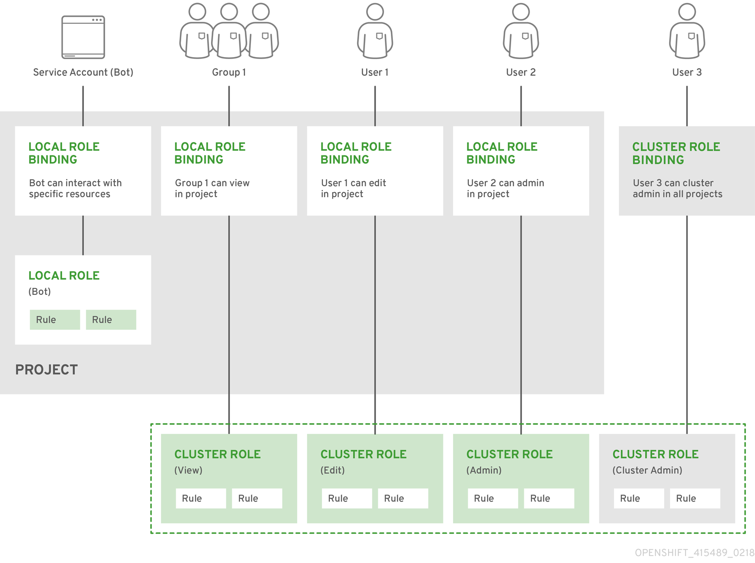
5.2.1.2. Evaluating authorization
OpenShift Container Platform evaluates authorization by using:
- Identity
- The user name and list of groups that the user belongs to.
- Action
The action you perform. In most cases, this consists of:
- Project: The project you access. A project is a Kubernetes namespace with additional annotations that allows a community of users to organize and manage their content in isolation from other communities.
-
Verb : The action itself:
get,list,create,update,delete,deletecollection, orwatch. - Resource name: The API endpoint that you access.
- Bindings
- The full list of bindings, the associations between users or groups with a role.
OpenShift Container Platform evaluates authorization by using the following steps:
- The identity and the project-scoped action is used to find all bindings that apply to the user or their groups.
- Bindings are used to locate all the roles that apply.
- Roles are used to find all the rules that apply.
- The action is checked against each rule to find a match.
- If no matching rule is found, the action is then denied by default.
Remember that users and groups can be associated with, or bound to, multiple roles at the same time.
Project administrators can use the CLI to view local roles and bindings, including a matrix of the verbs and resources each are associated with.
The cluster role bound to the project administrator is limited in a project through a local binding. It is not bound cluster-wide like the cluster roles granted to the cluster-admin or system:admin.
Cluster roles are roles defined at the cluster level but can be bound either at the cluster level or at the project level.
5.2.1.2.1. Cluster role aggregation
The default admin, edit, view, and cluster-reader cluster roles support cluster role aggregation, where the cluster rules for each role are dynamically updated as new rules are created. This feature is relevant only if you extend the Kubernetes API by creating custom resources.
5.2.2. Projects and namespaces
A Kubernetes namespace provides a mechanism to scope resources in a cluster. The Kubernetes documentation has more information on namespaces.
Namespaces provide a unique scope for:
- Named resources to avoid basic naming collisions.
- Delegated management authority to trusted users.
- The ability to limit community resource consumption.
Most objects in the system are scoped by namespace, but some are excepted and have no namespace, including nodes and users.
A project is a Kubernetes namespace with additional annotations and is the central vehicle by which access to resources for regular users is managed. A project allows a community of users to organize and manage their content in isolation from other communities. Users must be given access to projects by administrators, or if allowed to create projects, automatically have access to their own projects.
Projects can have a separate name, displayName, and description.
-
The mandatory
nameis a unique identifier for the project and is most visible when using the CLI tools or API. The maximum name length is 63 characters. -
The optional
displayNameis how the project is displayed in the web console (defaults toname). -
The optional
descriptioncan be a more detailed description of the project and is also visible in the web console.
Each project scopes its own set of:
| Object | Description |
|---|---|
|
| Pods, services, replication controllers, etc. |
|
| Rules for which users can or cannot perform actions on objects. |
|
| Quotas for each kind of object that can be limited. |
|
| Service accounts act automatically with designated access to objects in the project. |
Cluster administrators can create projects and delegate administrative rights for the project to any member of the user community. Cluster administrators can also allow developers to create their own projects.
Developers and administrators can interact with projects by using the CLI or the web console.
5.2.3. Default projects
OpenShift Container Platform comes with a number of default projects, and projects starting with openshift- are the most essential to users. These projects host master components that run as pods and other infrastructure components. The pods created in these namespaces that have a critical pod annotation are considered critical, and the have guaranteed admission by kubelet. Pods created for master components in these namespaces are already marked as critical.
You cannot assign an SCC to pods created in one of the default namespaces: default, kube-system, kube-public, openshift-node, openshift-infra, and openshift. You cannot use these namespaces for running pods or services.
5.2.4. Viewing cluster roles and bindings
You can use the oc CLI to view cluster roles and bindings by using the oc describe command.
Prerequisites
-
Install the
ocCLI. - Obtain permission to view the cluster roles and bindings.
Users with the cluster-admin default cluster role bound cluster-wide can perform any action on any resource, including viewing cluster roles and bindings.
Procedure
To view the cluster roles and their associated rule sets:
$ oc describe clusterrole.rbacExample output
Name: admin Labels: kubernetes.io/bootstrapping=rbac-defaults Annotations: rbac.authorization.kubernetes.io/autoupdate: true PolicyRule: Resources Non-Resource URLs Resource Names Verbs --------- ----------------- -------------- ----- .packages.apps.redhat.com [] [] [* create update patch delete get list watch] imagestreams [] [] [create delete deletecollection get list patch update watch create get list watch] imagestreams.image.openshift.io [] [] [create delete deletecollection get list patch update watch create get list watch] secrets [] [] [create delete deletecollection get list patch update watch get list watch create delete deletecollection patch update] buildconfigs/webhooks [] [] [create delete deletecollection get list patch update watch get list watch] buildconfigs [] [] [create delete deletecollection get list patch update watch get list watch] buildlogs [] [] [create delete deletecollection get list patch update watch get list watch] deploymentconfigs/scale [] [] [create delete deletecollection get list patch update watch get list watch] deploymentconfigs [] [] [create delete deletecollection get list patch update watch get list watch] imagestreamimages [] [] [create delete deletecollection get list patch update watch get list watch] imagestreammappings [] [] [create delete deletecollection get list patch update watch get list watch] imagestreamtags [] [] [create delete deletecollection get list patch update watch get list watch] processedtemplates [] [] [create delete deletecollection get list patch update watch get list watch] routes [] [] [create delete deletecollection get list patch update watch get list watch] templateconfigs [] [] [create delete deletecollection get list patch update watch get list watch] templateinstances [] [] [create delete deletecollection get list patch update watch get list watch] templates [] [] [create delete deletecollection get list patch update watch get list watch] deploymentconfigs.apps.openshift.io/scale [] [] [create delete deletecollection get list patch update watch get list watch] deploymentconfigs.apps.openshift.io [] [] [create delete deletecollection get list patch update watch get list watch] buildconfigs.build.openshift.io/webhooks [] [] [create delete deletecollection get list patch update watch get list watch] buildconfigs.build.openshift.io [] [] [create delete deletecollection get list patch update watch get list watch] buildlogs.build.openshift.io [] [] [create delete deletecollection get list patch update watch get list watch] imagestreamimages.image.openshift.io [] [] [create delete deletecollection get list patch update watch get list watch] imagestreammappings.image.openshift.io [] [] [create delete deletecollection get list patch update watch get list watch] imagestreamtags.image.openshift.io [] [] [create delete deletecollection get list patch update watch get list watch] routes.route.openshift.io [] [] [create delete deletecollection get list patch update watch get list watch] processedtemplates.template.openshift.io [] [] [create delete deletecollection get list patch update watch get list watch] templateconfigs.template.openshift.io [] [] [create delete deletecollection get list patch update watch get list watch] templateinstances.template.openshift.io [] [] [create delete deletecollection get list patch update watch get list watch] templates.template.openshift.io [] [] [create delete deletecollection get list patch update watch get list watch] serviceaccounts [] [] [create delete deletecollection get list patch update watch impersonate create delete deletecollection patch update get list watch] imagestreams/secrets [] [] [create delete deletecollection get list patch update watch] rolebindings [] [] [create delete deletecollection get list patch update watch] roles [] [] [create delete deletecollection get list patch update watch] rolebindings.authorization.openshift.io [] [] [create delete deletecollection get list patch update watch] roles.authorization.openshift.io [] [] [create delete deletecollection get list patch update watch] imagestreams.image.openshift.io/secrets [] [] [create delete deletecollection get list patch update watch] rolebindings.rbac.authorization.k8s.io [] [] [create delete deletecollection get list patch update watch] roles.rbac.authorization.k8s.io [] [] [create delete deletecollection get list patch update watch] networkpolicies.extensions [] [] [create delete deletecollection patch update create delete deletecollection get list patch update watch get list watch] networkpolicies.networking.k8s.io [] [] [create delete deletecollection patch update create delete deletecollection get list patch update watch get list watch] configmaps [] [] [create delete deletecollection patch update get list watch] endpoints [] [] [create delete deletecollection patch update get list watch] persistentvolumeclaims [] [] [create delete deletecollection patch update get list watch] pods [] [] [create delete deletecollection patch update get list watch] replicationcontrollers/scale [] [] [create delete deletecollection patch update get list watch] replicationcontrollers [] [] [create delete deletecollection patch update get list watch] services [] [] [create delete deletecollection patch update get list watch] daemonsets.apps [] [] [create delete deletecollection patch update get list watch] deployments.apps/scale [] [] [create delete deletecollection patch update get list watch] deployments.apps [] [] [create delete deletecollection patch update get list watch] replicasets.apps/scale [] [] [create delete deletecollection patch update get list watch] replicasets.apps [] [] [create delete deletecollection patch update get list watch] statefulsets.apps/scale [] [] [create delete deletecollection patch update get list watch] statefulsets.apps [] [] [create delete deletecollection patch update get list watch] horizontalpodautoscalers.autoscaling [] [] [create delete deletecollection patch update get list watch] cronjobs.batch [] [] [create delete deletecollection patch update get list watch] jobs.batch [] [] [create delete deletecollection patch update get list watch] daemonsets.extensions [] [] [create delete deletecollection patch update get list watch] deployments.extensions/scale [] [] [create delete deletecollection patch update get list watch] deployments.extensions [] [] [create delete deletecollection patch update get list watch] ingresses.extensions [] [] [create delete deletecollection patch update get list watch] replicasets.extensions/scale [] [] [create delete deletecollection patch update get list watch] replicasets.extensions [] [] [create delete deletecollection patch update get list watch] replicationcontrollers.extensions/scale [] [] [create delete deletecollection patch update get list watch] poddisruptionbudgets.policy [] [] [create delete deletecollection patch update get list watch] deployments.apps/rollback [] [] [create delete deletecollection patch update] deployments.extensions/rollback [] [] [create delete deletecollection patch update] catalogsources.operators.coreos.com [] [] [create update patch delete get list watch] clusterserviceversions.operators.coreos.com [] [] [create update patch delete get list watch] installplans.operators.coreos.com [] [] [create update patch delete get list watch] packagemanifests.operators.coreos.com [] [] [create update patch delete get list watch] subscriptions.operators.coreos.com [] [] [create update patch delete get list watch] buildconfigs/instantiate [] [] [create] buildconfigs/instantiatebinary [] [] [create] builds/clone [] [] [create] deploymentconfigrollbacks [] [] [create] deploymentconfigs/instantiate [] [] [create] deploymentconfigs/rollback [] [] [create] imagestreamimports [] [] [create] localresourceaccessreviews [] [] [create] localsubjectaccessreviews [] [] [create] podsecuritypolicyreviews [] [] [create] podsecuritypolicyselfsubjectreviews [] [] [create] podsecuritypolicysubjectreviews [] [] [create] resourceaccessreviews [] [] [create] routes/custom-host [] [] [create] subjectaccessreviews [] [] [create] subjectrulesreviews [] [] [create] deploymentconfigrollbacks.apps.openshift.io [] [] [create] deploymentconfigs.apps.openshift.io/instantiate [] [] [create] deploymentconfigs.apps.openshift.io/rollback [] [] [create] localsubjectaccessreviews.authorization.k8s.io [] [] [create] localresourceaccessreviews.authorization.openshift.io [] [] [create] localsubjectaccessreviews.authorization.openshift.io [] [] [create] resourceaccessreviews.authorization.openshift.io [] [] [create] subjectaccessreviews.authorization.openshift.io [] [] [create] subjectrulesreviews.authorization.openshift.io [] [] [create] buildconfigs.build.openshift.io/instantiate [] [] [create] buildconfigs.build.openshift.io/instantiatebinary [] [] [create] builds.build.openshift.io/clone [] [] [create] imagestreamimports.image.openshift.io [] [] [create] routes.route.openshift.io/custom-host [] [] [create] podsecuritypolicyreviews.security.openshift.io [] [] [create] podsecuritypolicyselfsubjectreviews.security.openshift.io [] [] [create] podsecuritypolicysubjectreviews.security.openshift.io [] [] [create] jenkins.build.openshift.io [] [] [edit view view admin edit view] builds [] [] [get create delete deletecollection get list patch update watch get list watch] builds.build.openshift.io [] [] [get create delete deletecollection get list patch update watch get list watch] projects [] [] [get delete get delete get patch update] projects.project.openshift.io [] [] [get delete get delete get patch update] namespaces [] [] [get get list watch] pods/attach [] [] [get list watch create delete deletecollection patch update] pods/exec [] [] [get list watch create delete deletecollection patch update] pods/portforward [] [] [get list watch create delete deletecollection patch update] pods/proxy [] [] [get list watch create delete deletecollection patch update] services/proxy [] [] [get list watch create delete deletecollection patch update] routes/status [] [] [get list watch update] routes.route.openshift.io/status [] [] [get list watch update] appliedclusterresourcequotas [] [] [get list watch] bindings [] [] [get list watch] builds/log [] [] [get list watch] deploymentconfigs/log [] [] [get list watch] deploymentconfigs/status [] [] [get list watch] events [] [] [get list watch] imagestreams/status [] [] [get list watch] limitranges [] [] [get list watch] namespaces/status [] [] [get list watch] pods/log [] [] [get list watch] pods/status [] [] [get list watch] replicationcontrollers/status [] [] [get list watch] resourcequotas/status [] [] [get list watch] resourcequotas [] [] [get list watch] resourcequotausages [] [] [get list watch] rolebindingrestrictions [] [] [get list watch] deploymentconfigs.apps.openshift.io/log [] [] [get list watch] deploymentconfigs.apps.openshift.io/status [] [] [get list watch] controllerrevisions.apps [] [] [get list watch] rolebindingrestrictions.authorization.openshift.io [] [] [get list watch] builds.build.openshift.io/log [] [] [get list watch] imagestreams.image.openshift.io/status [] [] [get list watch] appliedclusterresourcequotas.quota.openshift.io [] [] [get list watch] imagestreams/layers [] [] [get update get] imagestreams.image.openshift.io/layers [] [] [get update get] builds/details [] [] [update] builds.build.openshift.io/details [] [] [update] Name: basic-user Labels: <none> Annotations: openshift.io/description: A user that can get basic information about projects. rbac.authorization.kubernetes.io/autoupdate: true PolicyRule: Resources Non-Resource URLs Resource Names Verbs --------- ----------------- -------------- ----- selfsubjectrulesreviews [] [] [create] selfsubjectaccessreviews.authorization.k8s.io [] [] [create] selfsubjectrulesreviews.authorization.openshift.io [] [] [create] clusterroles.rbac.authorization.k8s.io [] [] [get list watch] clusterroles [] [] [get list] clusterroles.authorization.openshift.io [] [] [get list] storageclasses.storage.k8s.io [] [] [get list] users [] [~] [get] users.user.openshift.io [] [~] [get] projects [] [] [list watch] projects.project.openshift.io [] [] [list watch] projectrequests [] [] [list] projectrequests.project.openshift.io [] [] [list] Name: cluster-admin Labels: kubernetes.io/bootstrapping=rbac-defaults Annotations: rbac.authorization.kubernetes.io/autoupdate: true PolicyRule: Resources Non-Resource URLs Resource Names Verbs --------- ----------------- -------------- ----- *.* [] [] [*] [*] [] [*] ...To view the current set of cluster role bindings, which shows the users and groups that are bound to various roles:
$ oc describe clusterrolebinding.rbacExample output
Name: alertmanager-main Labels: <none> Annotations: <none> Role: Kind: ClusterRole Name: alertmanager-main Subjects: Kind Name Namespace ---- ---- --------- ServiceAccount alertmanager-main openshift-monitoring Name: basic-users Labels: <none> Annotations: rbac.authorization.kubernetes.io/autoupdate: true Role: Kind: ClusterRole Name: basic-user Subjects: Kind Name Namespace ---- ---- --------- Group system:authenticated Name: cloud-credential-operator-rolebinding Labels: <none> Annotations: <none> Role: Kind: ClusterRole Name: cloud-credential-operator-role Subjects: Kind Name Namespace ---- ---- --------- ServiceAccount default openshift-cloud-credential-operator Name: cluster-admin Labels: kubernetes.io/bootstrapping=rbac-defaults Annotations: rbac.authorization.kubernetes.io/autoupdate: true Role: Kind: ClusterRole Name: cluster-admin Subjects: Kind Name Namespace ---- ---- --------- Group system:masters Name: cluster-admins Labels: <none> Annotations: rbac.authorization.kubernetes.io/autoupdate: true Role: Kind: ClusterRole Name: cluster-admin Subjects: Kind Name Namespace ---- ---- --------- Group system:cluster-admins User system:admin Name: cluster-api-manager-rolebinding Labels: <none> Annotations: <none> Role: Kind: ClusterRole Name: cluster-api-manager-role Subjects: Kind Name Namespace ---- ---- --------- ServiceAccount default openshift-machine-api ...
5.2.5. Viewing local roles and bindings
You can use the oc CLI to view local roles and bindings by using the oc describe command.
Prerequisites
-
Install the
ocCLI. Obtain permission to view the local roles and bindings:
-
Users with the
cluster-admindefault cluster role bound cluster-wide can perform any action on any resource, including viewing local roles and bindings. -
Users with the
admindefault cluster role bound locally can view and manage roles and bindings in that project.
-
Users with the
Procedure
To view the current set of local role bindings, which show the users and groups that are bound to various roles for the current project:
$ oc describe rolebinding.rbacTo view the local role bindings for a different project, add the
-nflag to the command:$ oc describe rolebinding.rbac -n joe-projectExample output
Name: admin Labels: <none> Annotations: <none> Role: Kind: ClusterRole Name: admin Subjects: Kind Name Namespace ---- ---- --------- User kube:admin Name: system:deployers Labels: <none> Annotations: openshift.io/description: Allows deploymentconfigs in this namespace to rollout pods in this namespace. It is auto-managed by a controller; remove subjects to disa... Role: Kind: ClusterRole Name: system:deployer Subjects: Kind Name Namespace ---- ---- --------- ServiceAccount deployer joe-project Name: system:image-builders Labels: <none> Annotations: openshift.io/description: Allows builds in this namespace to push images to this namespace. It is auto-managed by a controller; remove subjects to disable. Role: Kind: ClusterRole Name: system:image-builder Subjects: Kind Name Namespace ---- ---- --------- ServiceAccount builder joe-project Name: system:image-pullers Labels: <none> Annotations: openshift.io/description: Allows all pods in this namespace to pull images from this namespace. It is auto-managed by a controller; remove subjects to disable. Role: Kind: ClusterRole Name: system:image-puller Subjects: Kind Name Namespace ---- ---- --------- Group system:serviceaccounts:joe-project
5.2.6. Adding roles to users
You can use the oc adm administrator CLI to manage the roles and bindings.
Binding, or adding, a role to users or groups gives the user or group the access that is granted by the role. You can add and remove roles to and from users and groups using oc adm policy commands.
You can bind any of the default cluster roles to local users or groups in your project.
Procedure
Add a role to a user in a specific project:
$ oc adm policy add-role-to-user <role> <user> -n <project>For example, you can add the
adminrole to thealiceuser injoeproject by running:$ oc adm policy add-role-to-user admin alice -n joeView the local role bindings and verify the addition in the output:
$ oc describe rolebinding.rbac -n <project>For example, to view the local role bindings for the
joeproject:$ oc describe rolebinding.rbac -n joeExample output
Name: admin Labels: <none> Annotations: <none> Role: Kind: ClusterRole Name: admin Subjects: Kind Name Namespace ---- ---- --------- User kube:admin Name: admin-0 Labels: <none> Annotations: <none> Role: Kind: ClusterRole Name: admin Subjects: Kind Name Namespace ---- ---- --------- User alice1 Name: system:deployers Labels: <none> Annotations: openshift.io/description: Allows deploymentconfigs in this namespace to rollout pods in this namespace. It is auto-managed by a controller; remove subjects to disa... Role: Kind: ClusterRole Name: system:deployer Subjects: Kind Name Namespace ---- ---- --------- ServiceAccount deployer joe Name: system:image-builders Labels: <none> Annotations: openshift.io/description: Allows builds in this namespace to push images to this namespace. It is auto-managed by a controller; remove subjects to disable. Role: Kind: ClusterRole Name: system:image-builder Subjects: Kind Name Namespace ---- ---- --------- ServiceAccount builder joe Name: system:image-pullers Labels: <none> Annotations: openshift.io/description: Allows all pods in this namespace to pull images from this namespace. It is auto-managed by a controller; remove subjects to disable. Role: Kind: ClusterRole Name: system:image-puller Subjects: Kind Name Namespace ---- ---- --------- Group system:serviceaccounts:joe- 1
- The
aliceuser has been added to theadminsRoleBinding.
5.2.7. Creating a local role
You can create a local role for a project and then bind it to a user.
Procedure
To create a local role for a project, run the following command:
$ oc create role <name> --verb=<verb> --resource=<resource> -n <project>In this command, specify:
-
<name>, the local role’s name -
<verb>, a comma-separated list of the verbs to apply to the role -
<resource>, the resources that the role applies to -
<project>, the project name
For example, to create a local role that allows a user to view pods in the
blueproject, run the following command:$ oc create role podview --verb=get --resource=pod -n blue-
To bind the new role to a user, run the following command:
$ oc adm policy add-role-to-user podview user2 --role-namespace=blue -n blue
5.2.8. Creating a cluster role
You can create a cluster role.
Procedure
To create a cluster role, run the following command:
$ oc create clusterrole <name> --verb=<verb> --resource=<resource>In this command, specify:
-
<name>, the local role’s name -
<verb>, a comma-separated list of the verbs to apply to the role -
<resource>, the resources that the role applies to
For example, to create a cluster role that allows a user to view pods, run the following command:
$ oc create clusterrole podviewonly --verb=get --resource=pod-
5.2.9. Local role binding commands
When you manage a user or group’s associated roles for local role bindings using the following operations, a project may be specified with the -n flag. If it is not specified, then the current project is used.
You can use the following commands for local RBAC management.
| Command | Description |
|---|---|
|
| Indicates which users can perform an action on a resource. |
|
| Binds a specified role to specified users in the current project. |
|
| Removes a given role from specified users in the current project. |
|
| Removes specified users and all of their roles in the current project. |
|
| Binds a given role to specified groups in the current project. |
|
| Removes a given role from specified groups in the current project. |
|
| Removes specified groups and all of their roles in the current project. |
5.2.10. Cluster role binding commands
You can also manage cluster role bindings using the following operations. The -n flag is not used for these operations because cluster role bindings use non-namespaced resources.
| Command | Description |
|---|---|
|
| Binds a given role to specified users for all projects in the cluster. |
|
| Removes a given role from specified users for all projects in the cluster. |
|
| Binds a given role to specified groups for all projects in the cluster. |
|
| Removes a given role from specified groups for all projects in the cluster. |
5.2.11. Creating a cluster admin
The cluster-admin role is required to perform administrator level tasks on the OpenShift Container Platform cluster, such as modifying cluster resources.
Prerequisites
- You must have created a user to define as the cluster admin.
Procedure
Define the user as a cluster admin:
$ oc adm policy add-cluster-role-to-user cluster-admin <user>
5.3. The kubeadmin user
OpenShift Container Platform creates a cluster administrator, kubeadmin, after the installation process completes.
This user has the cluster-admin role automatically applied and is treated as the root user for the cluster. The password is dynamically generated and unique to your OpenShift Container Platform environment. After installation completes the password is provided in the installation program’s output. For example:
INFO Install complete!
INFO Run 'export KUBECONFIG=<your working directory>/auth/kubeconfig' to manage the cluster with 'oc', the OpenShift CLI.
INFO The cluster is ready when 'oc login -u kubeadmin -p <provided>' succeeds (wait a few minutes).
INFO Access the OpenShift web-console here: https://console-openshift-console.apps.demo1.openshift4-beta-abcorp.com
INFO Login to the console with user: kubeadmin, password: <provided>5.3.1. Removing the kubeadmin user
After you define an identity provider and create a new cluster-admin user, you can remove the kubeadmin to improve cluster security.
If you follow this procedure before another user is a cluster-admin, then OpenShift Container Platform must be reinstalled. It is not possible to undo this command.
Prerequisites
- You must have configured at least one identity provider.
-
You must have added the
cluster-adminrole to a user. - You must be logged in as an administrator.
Procedure
Remove the
kubeadminsecrets:$ oc delete secrets kubeadmin -n kube-system
5.4. Image configuration resources
Understand and configure image registry settings.
5.4.1. Image controller configuration parameters
The image.config.openshift.io/cluster resource holds cluster-wide information about how to handle images. The canonical, and only valid name is cluster. Its spec offers the following configuration parameters.
| Parameter | Description |
|---|---|
|
|
Limits the container image registries from which normal users can import images. Set this list to the registries that you trust to contain valid images, and that you want applications to be able to import from. Users with permission to create images or Every element of this list contains a location of the registry specified by the registry domain name.
|
|
|
A reference to a config map containing additional CAs that should be trusted during
The namespace for this config map is |
|
|
Provides the host names for the default external image registry. The external hostname should be set only when the image registry is exposed externally. The first value is used in |
|
| Contains configuration that determines how the container runtime should treat individual registries when accessing images for builds and pods. For instance, whether or not to allow insecure access. It does not contain configuration for the internal cluster registry.
Either |
When the allowedRegistries parameter is defined, all registries, including registry.redhat.io and quay.io registries and the default internal image registry, are blocked unless explicitly listed. When using the parameter, to prevent pod failure, add all registries including the registry.redhat.io and quay.io registries and the internalRegistryHostname to the allowedRegistries list, as they are required by payload images within your environment. For disconnected clusters, mirror registries should also be added.
The status field of the image.config.openshift.io/cluster resource holds observed values from the cluster.
| Parameter | Description |
|---|---|
|
|
Set by the Image Registry Operator, which controls the |
|
|
Set by the Image Registry Operator, provides the external host names for the image registry when it is exposed externally. The first value is used in |
5.4.2. Configuring image settings
You can configure image registry settings by editing the image.config.openshift.io/cluster custom resource (CR). The Machine Config Operator (MCO) watches the image.config.openshift.io/cluster CR for any changes to the registries and reboots the nodes when it detects changes.
Procedure
Edit the
image.config.openshift.io/clustercustom resource:$ oc edit image.config.openshift.io/clusterThe following is an example
image.config.openshift.io/clusterCR:apiVersion: config.openshift.io/v1 kind: Image1 metadata: annotations: release.openshift.io/create-only: "true" creationTimestamp: "2019-05-17T13:44:26Z" generation: 1 name: cluster resourceVersion: "8302" selfLink: /apis/config.openshift.io/v1/images/cluster uid: e34555da-78a9-11e9-b92b-06d6c7da38dc spec: allowedRegistriesForImport:2 - domainName: quay.io insecure: false additionalTrustedCA:3 name: myconfigmap registrySources:4 allowedRegistries: - example.com - quay.io - registry.redhat.io - image-registry.openshift-image-registry.svc:5000 insecureRegistries: - insecure.com status: internalRegistryHostname: image-registry.openshift-image-registry.svc:5000- 1
Image: Holds cluster-wide information about how to handle images. The canonical, and only valid name iscluster.- 2
allowedRegistriesForImport: Limits the container image registries from which normal users may import images. Set this list to the registries that you trust to contain valid images, and that you want applications to be able to import from. Users with permission to create images orImageStreamMappingsfrom the API are not affected by this policy. Typically only cluster administrators have the appropriate permissions.- 3
additionalTrustedCA: A reference to a config map containing additional certificate authorities (CA) that are trusted during image stream import, pod image pull,openshift-image-registrypullthrough, and builds. The namespace for this config map isopenshift-config. The format of the config map is to use the registry hostname as the key, and the PEM certificate as the value, for each additional registry CA to trust.- 4
registrySources: Contains configuration that determines how the container runtime should treat individual registries when accessing images for builds and pods. For instance, whether or not to allow insecure access. It does not contain configuration for the internal cluster registry. This example listsallowedRegistries, which defines the registries that are allowed to be used. One of the registries listed is insecure.
To check that the changes are applied, list your nodes:
$ oc get nodesExample output
NAME STATUS ROLES AGE VERSION ci-ln-j5cd0qt-f76d1-vfj5x-master-0 Ready master 98m v1.19.0+7070803 ci-ln-j5cd0qt-f76d1-vfj5x-master-1 Ready,SchedulingDisabled master 99m v1.19.0+7070803 ci-ln-j5cd0qt-f76d1-vfj5x-master-2 Ready master 98m v1.19.0+7070803 ci-ln-j5cd0qt-f76d1-vfj5x-worker-b-nsnd4 Ready worker 90m v1.19.0+7070803 ci-ln-j5cd0qt-f76d1-vfj5x-worker-c-5z2gz NotReady,SchedulingDisabled worker 90m v1.19.0+7070803 ci-ln-j5cd0qt-f76d1-vfj5x-worker-d-stsjv Ready worker 90m v1.19.0+7070803
5.4.2.1. Configuring additional trust stores for image registry access
The image.config.openshift.io/cluster custom resource can contain a reference to a config map that contains additional certificate authorities to be trusted during image registry access.
Prerequisites
- The certificate authorities (CA) must be PEM-encoded.
Procedure
You can create a config map in the openshift-config namespace and use its name in AdditionalTrustedCA in the image.config.openshift.io custom resource to provide additional CAs that should be trusted when contacting external registries.
The config map key is the host name of a registry with the port for which this CA is to be trusted, and the base64-encoded certificate is the value, for each additional registry CA to trust.
Image registry CA config map example
apiVersion: v1
kind: ConfigMap
metadata:
name: my-registry-ca
data:
registry.example.com: |
-----BEGIN CERTIFICATE-----
...
-----END CERTIFICATE-----
registry-with-port.example.com..5000: |
-----BEGIN CERTIFICATE-----
...
-----END CERTIFICATE------ 1
- If the registry has the port, such as
registry-with-port.example.com:5000,:should be replaced with...
You can configure additional CAs with the following procedure.
To configure an additional CA:
$ oc create configmap registry-config --from-file=<external_registry_address>=ca.crt -n openshift-config$ oc edit image.config.openshift.io clusterspec: additionalTrustedCA: name: registry-config
5.4.2.2. Allowing insecure registries
You can add insecure registries by editing the image.config.openshift.io/cluster custom resource (CR). OpenShift Container Platform applies the changes to this CR to all nodes in the cluster.
Registries that do not use valid SSL certificates or do not require HTTPS connections are considered insecure.
Insecure external registries should be avoided to reduce possible security risks.
Procedure
Edit the
image.config.openshift.io/clusterCR:$ oc edit image.config.openshift.io/clusterThe following is an example
image.config.openshift.io/clusterCR with an insecure registries list:apiVersion: config.openshift.io/v1 kind: Image metadata: annotations: release.openshift.io/create-only: "true" creationTimestamp: "2019-05-17T13:44:26Z" generation: 1 name: cluster resourceVersion: "8302" selfLink: /apis/config.openshift.io/v1/images/cluster uid: e34555da-78a9-11e9-b92b-06d6c7da38dc spec: registrySources:1 insecureRegistries:2 - insecure.com allowedRegistries: - example.com - quay.io - registry.redhat.io - insecure.com3 status: internalRegistryHostname: image-registry.openshift-image-registry.svc:5000- 1
registrySources: Contains configurations that determine how the container runtime should treat individual registries when accessing images for builds and pods. It does not contain configuration for the internal cluster registry.- 2
- Specify an insecure registry.
- 3
- Ensure that any insecure registries are included in the
allowedRegistrieslist.
NoteWhen the
allowedRegistriesparameter is defined, all registries, including the registry.redhat.io and quay.io registries and the default internal image registry, are blocked unless explicitly listed. If you use the parameter, to prevent pod failure, add all registries including theregistry.redhat.ioandquay.ioregistries and theinternalRegistryHostnameto theallowedRegistrieslist, as they are required by payload images within your environment. For disconnected clusters, mirror registries should also be added.The Machine Config Operator (MCO) watches the
image.config.openshift.io/clusterCR for any changes to registries and reboots the nodes when it detects changes. Changes to the insecure and blocked registries appear in the/etc/containers/registries.conffile on each node.To check that the registries have been added to the policy file, use the following command on a node:
$ cat /host/etc/containers/registries.confThe following example indicates that images from the
insecure.comregistry is insecure and is allowed for image pulls and pushes.Example output
unqualified-search-registries = ["registry.access.redhat.com", "docker.io"] [[registry]] prefix = "" location = "insecure.com" insecure = true
5.4.2.3. Configuring image registry repository mirroring
Setting up container registry repository mirroring enables you to do the following:
- Configure your OpenShift Container Platform cluster to redirect requests to pull images from a repository on a source image registry and have it resolved by a repository on a mirrored image registry.
- Identify multiple mirrored repositories for each target repository, to make sure that if one mirror is down, another can be used.
The attributes of repository mirroring in OpenShift Container Platform include:
- Image pulls are resilient to registry downtimes.
- Clusters in restricted networks can pull images from critical locations, such as quay.io, and have registries behind a company firewall provide the requested images.
- A particular order of registries is tried when an image pull request is made, with the permanent registry typically being the last one tried.
-
The mirror information you enter is added to the
/etc/containers/registries.conffile on every node in the OpenShift Container Platform cluster. - When a node makes a request for an image from the source repository, it tries each mirrored repository in turn until it finds the requested content. If all mirrors fail, the cluster tries the source repository. If successful, the image is pulled to the node.
Setting up repository mirroring can be done in the following ways:
At OpenShift Container Platform installation:
By pulling container images needed by OpenShift Container Platform and then bringing those images behind your company’s firewall, you can install OpenShift Container Platform into a datacenter that is in a restricted network.
After OpenShift Container Platform installation:
Even if you don’t configure mirroring during OpenShift Container Platform installation, you can do so later using the
ImageContentSourcePolicyobject.
The following procedure provides a post-installation mirror configuration, where you create an ImageContentSourcePolicy object that identifies:
- The source of the container image repository you want to mirror.
- A separate entry for each mirror repository you want to offer the content requested from the source repository.
You can only configure global pull secrets for clusters that have an ImageContentSourcePolicy object. You cannot add a pull secret to a project.
Prerequisites
-
Access to the cluster as a user with the
cluster-adminrole.
Procedure
Configure mirrored repositories, by either:
- Setting up a mirrored repository with Red Hat Quay, as described in Red Hat Quay Repository Mirroring. Using Red Hat Quay allows you to copy images from one repository to another and also automatically sync those repositories repeatedly over time.
Using a tool such as
skopeoto copy images manually from the source directory to the mirrored repository.For example, after installing the skopeo RPM package on a Red Hat Enterprise Linux (RHEL) 7 or RHEL 8 system, use the
skopeocommand as shown in this example:$ skopeo copy \ docker://registry.access.redhat.com/ubi8/ubi-minimal@sha256:5cfbaf45ca96806917830c183e9f37df2e913b187adb32e89fd83fa455ebaa6 \ docker://example.io/example/ubi-minimalIn this example, you have a container image registry that is named
example.iowith an image repository namedexampleto which you want to copy theubi8/ubi-minimalimage fromregistry.access.redhat.com. After you create the registry, you can configure your OpenShift Container Platform cluster to redirect requests made of the source repository to the mirrored repository.
- Log in to your OpenShift Container Platform cluster.
Create an
ImageContentSourcePolicyfile (for example,registryrepomirror.yaml), replacing the source and mirrors with your own registry and repository pairs and images:apiVersion: operator.openshift.io/v1alpha1 kind: ImageContentSourcePolicy metadata: name: ubi8repo spec: repositoryDigestMirrors: - mirrors: - example.io/example/ubi-minimal1 source: registry.access.redhat.com/ubi8/ubi-minimal2 - mirrors: - example.com/example/ubi-minimal source: registry.access.redhat.com/ubi8/ubi-minimalCreate the new
ImageContentSourcePolicyobject:$ oc create -f registryrepomirror.yamlAfter the
ImageContentSourcePolicyobject is created, the new settings are deployed to each node and the cluster starts using the mirrored repository for requests to the source repository.To check that the mirrored configuration settings, are applied, do the following on one of the nodes.
List your nodes:
$ oc get nodeExample output
NAME STATUS ROLES AGE VERSION ip-10-0-137-44.ec2.internal Ready worker 7m v1.18.3 ip-10-0-138-148.ec2.internal Ready master 11m v1.18.3 ip-10-0-139-122.ec2.internal Ready master 11m v1.18.3 ip-10-0-147-35.ec2.internal Ready,SchedulingDisabled worker 7m v1.18.3 ip-10-0-153-12.ec2.internal Ready worker 7m v1.18.3 ip-10-0-154-10.ec2.internal Ready master 11m v1.18.3You can see that scheduling on each worker node is disabled as the change is being applied.
Start the debugging process to access the node:
$ oc debug node/ip-10-0-147-35.ec2.internalExample output
Starting pod/ip-10-0-147-35ec2internal-debug ... To use host binaries, run `chroot /host`Access the node’s files:
sh-4.2# chroot /hostCheck the
/etc/containers/registries.conffile to make sure the changes were made:sh-4.2# cat /etc/containers/registries.confExample output
unqualified-search-registries = ["registry.access.redhat.com", "docker.io"] [[registry]] location = "registry.access.redhat.com/ubi8/" insecure = false blocked = false mirror-by-digest-only = true prefix = "" [[registry.mirror]] location = "example.io/example/ubi8-minimal" insecure = false [[registry.mirror]] location = "example.com/example/ubi8-minimal" insecure = falsePull an image digest to the node from the source and check if it is resolved by the mirror.
ImageContentSourcePolicyobjects support image digests only, not image tags.sh-4.2# podman pull --log-level=debug registry.access.redhat.com/ubi8/ubi-minimal@sha256:5cfbaf45ca96806917830c183e9f37df2e913b187adb32e89fd83fa455ebaa6
Troubleshooting repository mirroring
If the repository mirroring procedure does not work as described, use the following information about how repository mirroring works to help troubleshoot the problem.
- The first working mirror is used to supply the pulled image.
- The main registry is only used if no other mirror works.
-
From the system context, the
Insecureflags are used as fallback. -
The format of the
/etc/containers/registries.conffile has changed recently. It is now version 2 and in TOML format.
5.5. Operator installation with OperatorHub
OperatorHub is a user interface for discovering Operators; it works in conjunction with Operator Lifecycle Manager (OLM), which installs and manages Operators on a cluster.
As a cluster administrator, you can install an Operator from OperatorHub using the OpenShift Container Platform web console or CLI. Subscribing an Operator to one or more namespaces makes the Operator available to developers on your cluster.
During installation, you must determine the following initial settings for the Operator:
- Installation Mode
- Choose All namespaces on the cluster (default) to have the Operator installed on all namespaces or choose individual namespaces, if available, to only install the Operator on selected namespaces. This example chooses All namespaces… to make the Operator available to all users and projects.
- Update Channel
- If an Operator is available through multiple channels, you can choose which channel you want to subscribe to. For example, to deploy from the stable channel, if available, select it from the list.
- Approval Strategy
You can choose automatic or manual updates.
If you choose automatic updates for an installed Operator, when a new version of that Operator is available in the selected channel, Operator Lifecycle Manager (OLM) automatically upgrades the running instance of your Operator without human intervention.
If you select manual updates, when a newer version of an Operator is available, OLM creates an update request. As a cluster administrator, you must then manually approve that update request to have the Operator updated to the new version.
5.5.1. Installing from OperatorHub using the web console
You can install and subscribe to an Operator from OperatorHub using the OpenShift Container Platform web console.
Prerequisites
-
Access to an OpenShift Container Platform cluster using an account with
cluster-adminpermissions.
Procedure
- Navigate in the web console to the Operators → OperatorHub page.
Scroll or type a keyword into the Filter by keyword box to find the Operator you want. For example, type
jaegerto find the Jaeger Operator.You can also filter options by Infrastructure Features. For example, select Disconnected if you want to see Operators that work in disconnected environments, also known as restricted network environments.
Select the Operator to display additional information.
NoteChoosing a Community Operator warns that Red Hat does not certify Community Operators; you must acknowledge the warning before continuing.
- Read the information about the Operator and click Install.
On the Install Operator page:
Select one of the following:
-
All namespaces on the cluster (default) installs the Operator in the default
openshift-operatorsnamespace to watch and be made available to all namespaces in the cluster. This option is not always available. - A specific namespace on the cluster allows you to choose a specific, single namespace in which to install the Operator. The Operator will only watch and be made available for use in this single namespace.
-
All namespaces on the cluster (default) installs the Operator in the default
- Select an Update Channel (if more than one is available).
- Select Automatic or Manual approval strategy, as described earlier.
Click Install to make the Operator available to the selected namespaces on this OpenShift Container Platform cluster.
If you selected a Manual approval strategy, the upgrade status of the subscription remains Upgrading until you review and approve the install plan.
After approving on the Install Plan page, the subscription upgrade status moves to Up to date.
- If you selected an Automatic approval strategy, the upgrade status should resolve to Up to date without intervention.
After the upgrade status of the subscription is Up to date, select Operators → Installed Operators to verify that the cluster service version (CSV) of the installed Operator eventually shows up. The Status should ultimately resolve to InstallSucceeded in the relevant namespace.
NoteFor the All namespaces… installation mode, the status resolves to InstallSucceeded in the
openshift-operatorsnamespace, but the status is Copied if you check in other namespaces.If it does not:
-
Check the logs in any pods in the
openshift-operatorsproject (or other relevant namespace if A specific namespace… installation mode was selected) on the Workloads → Pods page that are reporting issues to troubleshoot further.
-
Check the logs in any pods in the
5.5.2. Installing from OperatorHub using the CLI
Instead of using the OpenShift Container Platform web console, you can install an Operator from OperatorHub using the CLI. Use the oc command to create or update a Subscription object.
Prerequisites
-
Access to an OpenShift Container Platform cluster using an account with
cluster-adminpermissions. -
Install the
occommand to your local system.
Procedure
View the list of Operators available to the cluster from OperatorHub:
$ oc get packagemanifests -n openshift-marketplaceExample output
NAME CATALOG AGE 3scale-operator Red Hat Operators 91m advanced-cluster-management Red Hat Operators 91m amq7-cert-manager Red Hat Operators 91m ... couchbase-enterprise-certified Certified Operators 91m crunchy-postgres-operator Certified Operators 91m mongodb-enterprise Certified Operators 91m ... etcd Community Operators 91m jaeger Community Operators 91m kubefed Community Operators 91m ...Note the catalog for your desired Operator.
Inspect your desired Operator to verify its supported install modes and available channels:
$ oc describe packagemanifests <operator_name> -n openshift-marketplaceAn Operator group, defined by an
OperatorGroupobject, selects target namespaces in which to generate required RBAC access for all Operators in the same namespace as the Operator group.The namespace to which you subscribe the Operator must have an Operator group that matches the install mode of the Operator, either the
AllNamespacesorSingleNamespacemode. If the Operator you intend to install uses theAllNamespaces, then theopenshift-operatorsnamespace already has an appropriate Operator group in place.However, if the Operator uses the
SingleNamespacemode and you do not already have an appropriate Operator group in place, you must create one.NoteThe web console version of this procedure handles the creation of the
OperatorGroupandSubscriptionobjects automatically behind the scenes for you when choosingSingleNamespacemode.Create an
OperatorGroupobject YAML file, for exampleoperatorgroup.yaml:Example
OperatorGroupobjectapiVersion: operators.coreos.com/v1 kind: OperatorGroup metadata: name: <operatorgroup_name> namespace: <namespace> spec: targetNamespaces: - <namespace>Create the
OperatorGroupobject:$ oc apply -f operatorgroup.yaml
Create a
Subscriptionobject YAML file to subscribe a namespace to an Operator, for examplesub.yaml:Example
SubscriptionobjectapiVersion: operators.coreos.com/v1alpha1 kind: Subscription metadata: name: <subscription_name> namespace: openshift-operators1 spec: channel: <channel_name>2 name: <operator_name>3 source: redhat-operators4 sourceNamespace: openshift-marketplace5 - 1
- For
AllNamespacesinstall mode usage, specify theopenshift-operatorsnamespace. Otherwise, specify the relevant single namespace forSingleNamespaceinstall mode usage. - 2
- Name of the channel to subscribe to.
- 3
- Name of the Operator to subscribe to.
- 4
- Name of the catalog source that provides the Operator.
- 5
- Namespace of the catalog source. Use
openshift-marketplacefor the default OperatorHub catalog sources.
Create the
Subscriptionobject:$ oc apply -f sub.yamlAt this point, OLM is now aware of the selected Operator. A cluster service version (CSV) for the Operator should appear in the target namespace, and APIs provided by the Operator should be available for creation.
Additional resources
Legal Notice
Copyright © Red Hat
OpenShift documentation is licensed under the Apache License 2.0 (https://www.apache.org/licenses/LICENSE-2.0).
Modified versions must remove all Red Hat trademarks.
Portions adapted from https://github.com/kubernetes-incubator/service-catalog/ with modifications by Red Hat.
Red Hat, Red Hat Enterprise Linux, the Red Hat logo, the Shadowman logo, JBoss, OpenShift, Fedora, the Infinity logo, and RHCE are trademarks of Red Hat, Inc., registered in the United States and other countries.
Linux® is the registered trademark of Linus Torvalds in the United States and other countries.
Java® is a registered trademark of Oracle and/or its affiliates.
XFS® is a trademark of Silicon Graphics International Corp. or its subsidiaries in the United States and/or other countries.
MySQL® is a registered trademark of MySQL AB in the United States, the European Union and other countries.
Node.js® is an official trademark of the OpenJS Foundation.
The OpenStack® Word Mark and OpenStack logo are either registered trademarks/service marks or trademarks/service marks of the OpenStack Foundation, in the United States and other countries and are used with the OpenStack Foundation’s permission. We are not affiliated with, endorsed or sponsored by the OpenStack Foundation, or the OpenStack community.
All other trademarks are the property of their respective owners.