Installing on bare metal
Installing OpenShift Container Platform on bare metal
Abstract
Chapter 1. Preparing for bare metal cluster installation
1.1. Prerequisites
- You reviewed details about the OpenShift Container Platform installation and update processes.
- You have read the documentation on selecting a cluster installation method and preparing it for users.
- You have read the documentation for supported and unsupported OVN-Kubernetes network plugin use cases on OVN-Kubernetes purpose.
1.2. Bare-metal cluster installation requirements for OpenShift Virtualization
If you plan to use OpenShift Virtualization on a bare-metal cluster, you must ensure that your cluster is configured correctly during installation. This is because OpenShift Virtualization requires certain settings that cannot be changed after a cluster is installed.
1.2.1. High availability requirements for OpenShift Virtualization
When discussing high availability (HA) features in the context of OpenShift Virtualization, this refers only to the replication model of the core cluster components, determined by the controlPlaneTopology and infrastructureTopology fields in the Infrastructure custom resource (CR). Setting these fields to HighlyAvailable offers component redundancy, which is distinct from general cluster-wide application HA. Setting these fields to SingleReplica disables component redundancy, and therefore disables OpenShift Virtualization HA features.
If you plan to use OpenShift Virtualization HA features, you must have three control plane nodes at the time of cluster installation. The controlPlaneTopology status in the Infrastructure CR for the cluster must be HighlyAvailable.
You can install OpenShift Virtualization on a single-node cluster, but single-node OpenShift does not support HA features.
1.2.2. Live migration requirements for OpenShift Virtualization
If you plan to use live migration, you must have multiple worker nodes. The
infrastructureTopologystatus in theInfrastructureCR for the cluster must beHighlyAvailable, and a minimum of three worker nodes is recommended.NoteYou can install OpenShift Virtualization on a single-node cluster, but single-node OpenShift does not support live migration.
- Live migration requires shared storage. Storage for OpenShift Virtualization must support and use the ReadWriteMany (RWX) access mode.
1.2.3. SR-IOV requirements for OpenShift Virtualization
If you plan to use Single Root I/O Virtualization (SR-IOV), ensure that your network interface controllers (NICs) are supported by OpenShift Container Platform.
1.3. NIC partitioning for SR-IOV devices
OpenShift Container Platform can be deployed on a server with a dual port network interface card (NIC). You can partition a single, high-speed dual port NIC into multiple virtual functions (VFs) and enable SR-IOV.
This feature supports the use of bonds for high availability with the Link Aggregation Control Protocol (LACP).
Only one LACP can be declared by physical NIC.
An OpenShift Container Platform cluster can be deployed on a bond interface with 2 VFs on 2 physical functions (PFs) using the following methods:
Agent-based installer
NoteThe minimum required version of
nmstateis:-
1.4.2-4for RHEL 8 versions -
2.2.7for RHEL 9 versions
-
- Installer-provisioned infrastructure installation
- User-provisioned infrastructure installation
1.4. Choosing a method to install OpenShift Container Platform on bare metal
The OpenShift Container Platform installation program offers four methods for deploying a cluster:
- Interactive: You can deploy a cluster with the web-based Assisted Installer. This is the recommended approach for clusters with networks connected to the internet. The Assisted Installer is the easiest way to install OpenShift Container Platform, it provides smart defaults, and it performs pre-flight validations before installing the cluster. It also provides a RESTful API for automation and advanced configuration scenarios.
- Local Agent-based: You can deploy a cluster locally with the agent-based installer for air-gapped or restricted networks. It provides many of the benefits of the Assisted Installer, but you must download and configure the agent-based installer first. Configuration is done with a commandline interface. This approach is ideal for air-gapped or restricted networks.
- Automated: You can deploy a cluster on installer-provisioned infrastructure and the cluster it maintains. The installer uses each cluster host’s baseboard management controller (BMC) for provisioning. You can deploy clusters with both connected or air-gapped or restricted networks.
- Full control: You can deploy a cluster on infrastructure that you prepare and maintain, which provides maximum customizability. You can deploy clusters with both connected or air-gapped or restricted networks.
The clusters have the following characteristics:
- Highly available infrastructure with no single points of failure is available by default.
- Administrators maintain control over what updates are applied and when.
See Installation process for more information about installer-provisioned and user-provisioned installation processes.
1.4.1. Installing a cluster on installer-provisioned infrastructure
You can install a cluster on bare metal infrastructure that is provisioned by the OpenShift Container Platform installation program, by using the following method:
- Installing an installer-provisioned cluster on bare metal: You can install OpenShift Container Platform on bare metal by using installer provisioning.
1.4.2. Installing a cluster on user-provisioned infrastructure
You can install a cluster on bare metal infrastructure that you provision, by using one of the following methods:
- Installing a user-provisioned cluster on bare metal: You can install OpenShift Container Platform on bare metal infrastructure that you provision. For a cluster that contains user-provisioned infrastructure, you must deploy all of the required machines.
- Installing a user-provisioned bare metal cluster with network customizations: You can install a bare metal cluster on user-provisioned infrastructure with network-customizations. By customizing your network configuration, your cluster can coexist with existing IP address allocations in your environment and integrate with existing MTU and VXLAN configurations. Most of the network customizations must be applied at the installation stage.
- Installing a user-provisioned bare metal cluster on a restricted network: You can install a user-provisioned bare metal cluster on a restricted or disconnected network by using a mirror registry. You can also use this installation method to ensure that your clusters only use container images that satisfy your organizational controls on external content.
Chapter 2. User-provisioned infrastructure
2.1. Installing a user-provisioned cluster on bare metal
To optimize performance and maintain more control over your hardware in OpenShift Container Platform 4.18, you can install a cluster on bare-metal infrastructure that you provision.
While you might be able to follow this procedure to deploy a cluster on virtualized or cloud environments, you must be aware of additional considerations for non-bare-metal platforms. Review the information in the guidelines for deploying OpenShift Container Platform on non-tested platforms before you attempt to install an OpenShift Container Platform cluster in such an environment.
2.1.1. Prerequisites
- You reviewed details about the OpenShift Container Platform installation and update processes.
- You read the documentation on selecting a cluster installation method and preparing it for users.
If you use a firewall, you configured it to allow the sites that your cluster requires access to.
NoteBe sure to also review this site list if you are configuring a proxy.
2.1.2. Internet access for OpenShift Container Platform
In OpenShift Container Platform 4.18, you require access to the internet to install your cluster.
You must have internet access to perform the following actions:
- Access OpenShift Cluster Manager to download the installation program and perform subscription management. If the cluster has internet access and you do not disable Telemetry, that service automatically entitles your cluster.
- Access Quay.io to obtain the packages that are required to install your cluster.
- Obtain the packages that are required to perform cluster updates.
If your cluster cannot have direct internet access, you can perform a restricted network installation on some types of infrastructure that you provision. During that process, you download the required content and use it to populate a mirror registry with the installation packages. With some installation types, the environment that you install your cluster in will not require internet access. Before you update the cluster, you update the content of the mirror registry.
2.1.2.1. Required machines for cluster installation
You must specify the minimum required machines or hosts for your cluster so that your cluster remains stable if a node fails.
The smallest OpenShift Container Platform clusters require the following hosts:
For a cluster that contains user-provisioned infrastructure, you must deploy all of the required machines.
| Hosts | Description |
|---|---|
| One temporary bootstrap machine | The cluster requires the bootstrap machine to deploy the OpenShift Container Platform cluster on the three control plane machines. You can remove the bootstrap machine after you install the cluster. |
| Three control plane machines | The control plane machines run the Kubernetes and OpenShift Container Platform services that form the control plane. |
| At least two compute machines, which are also known as worker machines. | The workloads requested by OpenShift Container Platform users run on the compute machines. |
As an exception, you can run zero compute machines in a bare metal cluster that consists of three control plane machines only. This provides smaller, more resource efficient clusters for cluster administrators and developers to use for testing, development, and production. Running one compute machine is not supported.
To maintain high availability of your cluster, use separate physical hosts for these cluster machines.
The bootstrap and control plane machines must use Red Hat Enterprise Linux CoreOS (RHCOS) as the operating system. However, the compute machines can choose between Red Hat Enterprise Linux CoreOS (RHCOS), Red Hat Enterprise Linux (RHEL) 8.6 and later.
Note that RHCOS is based on Red Hat Enterprise Linux (RHEL) 9.2 and inherits all of its hardware certifications and requirements. See Red Hat Enterprise Linux technology capabilities and limits.
2.1.2.2. Minimum resource requirements for cluster installation
Each created cluster must meet minimum requirements so that the cluster runs as expected.
| Machine | Operating System | CPU [1] | RAM | Storage | Input/Output Per Second (IOPS)[2] |
|---|---|---|---|---|---|
| Bootstrap | RHCOS | 4 | 16 GB | 100 GB | 300 |
| Control plane | RHCOS | 4 | 16 GB | 100 GB | 300 |
| Compute | RHCOS, RHEL 8.6 and later [3] | 2 | 8 GB | 100 GB | 300 |
- One CPU is equivalent to one physical core when simultaneous multithreading (SMT), or Hyper-Threading, is not enabled. When enabled, use the following formula to calculate the corresponding ratio: (threads per core × cores) × sockets = CPUs.
- OpenShift Container Platform and Kubernetes are sensitive to disk performance, and faster storage is recommended, particularly for etcd on the control plane nodes which require a 10 ms p99 fsync duration. Note that on many cloud platforms, storage size and IOPS scale together, so you might need to over-allocate storage volume to obtain sufficient performance.
- As with all user-provisioned installations, if you choose to use RHEL compute machines in your cluster, you take responsibility for all operating system life cycle management and maintenance, including performing system updates, applying patches, and completing all other required tasks. Use of RHEL 7 compute machines is deprecated and has been removed in OpenShift Container Platform 4.10 and later.
For OpenShift Container Platform version 4.18, RHCOS is based on RHEL version 9.4, which updates the micro-architecture requirements. The following list contains the minimum instruction set architectures (ISA) that each architecture requires:
- x86-64 architecture requires x86-64-v2 ISA
- ARM64 architecture requires ARMv8.0-A ISA
- IBM Power architecture requires Power 9 ISA
- s390x architecture requires z14 ISA
For more information, see Architectures (RHEL documentation).
If an instance type for your platform meets the minimum requirements for cluster machines, it is supported to use in OpenShift Container Platform.
2.1.2.3. Certificate signing requests management
On user-provisioned infrastructure, you must provide a mechanism for approving cluster certificate signing requests (CSRs) after installation when your cluster has limited access to automatic machine management.
The kube-controller-manager only approves the kubelet client CSRs. The machine-approver cannot guarantee the validity of a serving certificate that is requested by using kubelet credentials because it cannot confirm that the correct machine issued the request. You must determine and implement a method of verifying the validity of the kubelet serving certificate requests and approving them.
2.1.2.4. Networking requirements for user-provisioned infrastructure
You must configure networking for all the Red Hat Enterprise Linux CoreOS (RHCOS) machines in initramfs during boot, so that they can fetch their Ignition config files.
During the initial boot, the machines require an IP address configuration that is set either through a DHCP server or statically by providing the required boot options. After a network connection is established, the machines download their Ignition config files from an HTTP or HTTPS server. The Ignition config files are then used to set the exact state of each machine. The Machine Config Operator completes more changes to the machines, such as the application of new certificates or keys, after installation.
- Consider using a DHCP server for long-term management of the cluster machines. Ensure that the DHCP server is configured to provide persistent IP addresses, DNS server information, and hostnames to the cluster machines.
- If a DHCP service is not available for your user-provisioned infrastructure, you can instead provide the IP networking configuration and the address of the DNS server to the nodes at RHCOS install time. These can be passed as boot arguments if you are installing from an ISO image. See the Installing RHCOS and starting the OpenShift Container Platform bootstrap process section for more information about static IP provisioning and advanced networking options.
The Kubernetes API server must be able to resolve the node names of the cluster machines. If the API servers and worker nodes are in different zones, you can configure a default DNS search zone to allow the API server to resolve the node names. Another supported approach is to always refer to hosts by their fully-qualified domain names in both the node objects and all DNS requests.
2.1.2.4.1. Setting the cluster node hostnames through DHCP
On Red Hat Enterprise Linux CoreOS (RHCOS) machines, the hostname is set through NetworkManager. By default, the machines obtain their hostname through DHCP. If the hostname is not provided by DHCP, set statically through kernel arguments, or another method, it is obtained through a reverse DNS lookup. Reverse DNS lookup occurs after the network has been initialized on a node and can take time to resolve. Other system services can start prior to this and detect the hostname as localhost or similar. You can avoid this by using DHCP to provide the hostname for each cluster node.
Additionally, setting the hostnames through DHCP can bypass any manual DNS record name configuration errors in environments that have a DNS split-horizon implementation.
2.1.2.4.2. Network connectivity requirements
You must configure the network connectivity between machines to allow OpenShift Container Platform cluster components to communicate. Each machine must be able to resolve the hostnames of all other machines in the cluster.
This section provides details about the ports that are required.
In connected OpenShift Container Platform environments, all nodes are required to have internet access to pull images for platform containers and provide telemetry data to Red Hat.
| Protocol | Port | Description |
|---|---|---|
| ICMP | N/A | Network reachability tests |
| TCP |
| Metrics |
|
|
Host level services, including the node exporter on ports | |
|
| The default ports that Kubernetes reserves | |
|
| The port handles traffic from the Machine Config Server and directs the traffic to the control plane machines. | |
| UDP |
| Geneve |
|
|
Host level services, including the node exporter on ports | |
|
| IPsec IKE packets | |
|
| IPsec NAT-T packets | |
|
|
Network Time Protocol (NTP) on UDP port | |
| TCP/UDP |
| |
| Kubernetes node port | ESP | N/A |
| Protocol | Port | Description |
|---|---|---|
| TCP |
| Kubernetes API |
| Protocol | Port | Description |
|---|---|---|
| TCP |
| etcd server and peer ports |
2.1.2.4.3. NTP configuration for user-provisioned infrastructure
OpenShift Container Platform clusters are configured to use a public Network Time Protocol (NTP) server by default. If you want to use a local enterprise NTP server, or if your cluster is being deployed in a disconnected network, you can configure the cluster to use a specific time server. For more information, see the documentation for Configuring chrony time service.
If a DHCP server provides NTP server information, the chrony time service on the Red Hat Enterprise Linux CoreOS (RHCOS) machines read the information and can sync the clock with the NTP servers.
2.1.2.5. User-provisioned DNS requirements
In OpenShift Container Platform deployments, you must ensure that cluster components meet certain DNS name resolution criteria for internal communication, certificate validation, and automated node discovery purposes.
The following is a list of required cluster components:
- The Kubernetes API
- The OpenShift Container Platform application wildcard
- The bootstrap, control plane, and compute machines
Reverse DNS resolution is also required for the Kubernetes API, the bootstrap machine, the control plane machines, and the compute machines.
DNS A/AAAA or CNAME records are used for name resolution and PTR records are used for reverse name resolution. The reverse records are important because Red Hat Enterprise Linux CoreOS (RHCOS) uses the reverse records to set the hostnames for all the nodes, unless the hostnames are provided by DHCP. Additionally, the reverse records are used to generate the certificate signing requests (CSR) that OpenShift Container Platform needs to operate.
It is recommended to use a DHCP server to provide the hostnames to each cluster node. See the DHCP recommendations for user-provisioned infrastructure section for more information.
The following DNS records are required for a user-provisioned OpenShift Container Platform cluster and they must be in place before installation. In each record, <cluster_name> is the cluster name and <base_domain> is the base domain that you specify in the install-config.yaml file. A complete DNS record takes the form: <component>.<cluster_name>.<base_domain>..
| Component | Record | Description |
|---|---|---|
| Kubernetes API |
| A DNS A/AAAA or CNAME record, and a DNS PTR record, to identify the API load balancer. These records must be resolvable by both clients external to the cluster and from all the nodes within the cluster. |
|
| A DNS A/AAAA or CNAME record, and a DNS PTR record, to internally identify the API load balancer. These records must be resolvable from all the nodes within the cluster. Important The API server must be able to resolve the worker nodes by the hostnames that are recorded in Kubernetes. If the API server cannot resolve the node names, then proxied API calls can fail, and you cannot retrieve logs from pods. | |
| Routes |
| A wildcard DNS A/AAAA or CNAME record that refers to the application ingress load balancer. The application ingress load balancer targets the machines that run the Ingress Controller pods. The Ingress Controller pods run on the compute machines by default. These records must be resolvable by both clients external to the cluster and from all the nodes within the cluster.
For example, |
| Bootstrap machine |
| A DNS A/AAAA or CNAME record, and a DNS PTR record, to identify the bootstrap machine. These records must be resolvable by the nodes within the cluster. |
| Control plane machines |
| DNS A/AAAA or CNAME records and DNS PTR records to identify each machine for the control plane nodes. These records must be resolvable by the nodes within the cluster. |
| Compute machines |
| DNS A/AAAA or CNAME records and DNS PTR records to identify each machine for the worker nodes. These records must be resolvable by the nodes within the cluster. |
In OpenShift Container Platform 4.4 and later, you do not need to specify etcd host and SRV records in your DNS configuration.
You can use the dig command to verify name and reverse name resolution. See the section on Validating DNS resolution for user-provisioned infrastructure for detailed validation steps.
2.1.2.5.1. Example DNS configuration for user-provisioned clusters
Reference the example DNS configurations to understand how A and PTR record configuration samples meet the DNS requirements for deploying OpenShift Container Platform on user-provisioned infrastructure.
The DNS configuration examples provided here are for reference only and are not meant to provide advice for choosing one DNS solution over another.
In the examples, the cluster name is ocp4 and the base domain is example.com.
The following example is a BIND zone file that shows sample DNS A records for name resolution in a user-provisioned cluster.
In the example, the same load balancer is used for the Kubernetes API and application ingress traffic. In production scenarios, you can deploy the API and application ingress load balancers separately so that you can scale the load balancer infrastructure for each in isolation.
$TTL 1W
@ IN SOA ns1.example.com. root (
2019070700 ; serial
3H ; refresh (3 hours)
30M ; retry (30 minutes)
2W ; expiry (2 weeks)
1W ) ; minimum (1 week)
IN NS ns1.example.com.
IN MX 10 smtp.example.com.
;
;
ns1.example.com. IN A 192.168.1.5
smtp.example.com. IN A 192.168.1.5
;
helper.example.com. IN A 192.168.1.5
helper.ocp4.example.com. IN A 192.168.1.5
;
api.ocp4.example.com. IN A 192.168.1.5
api-int.ocp4.example.com. IN A 192.168.1.5
;
*.apps.ocp4.example.com. IN A 192.168.1.5
;
bootstrap.ocp4.example.com. IN A 192.168.1.96
;
control-plane0.ocp4.example.com. IN A 192.168.1.97
control-plane1.ocp4.example.com. IN A 192.168.1.98
;
control-plane2.ocp4.example.com. IN A 192.168.1.99
;
compute0.ocp4.example.com. IN A 192.168.1.11
compute1.ocp4.example.com. IN A 192.168.1.7
;
;EOFwhere:
api.ocp4.example.com.- Provides name resolution for the Kubernetes API. The record refers to the IP address of the API load balancer.
api-int.ocp4.example.com.- Provides name resolution for the Kubernetes API. The record refers to the IP address of the API load balancer and is used for internal cluster communications.
*.apps.ocp4.example.com.- Provides name resolution for the wildcard routes. The record refers to the IP address of the application ingress load balancer. The application ingress load balancer targets the machines that run the Ingress Controller pods.
bootstrap.ocp4.example.com- Provides name resolution for the bootstrap machine.
control-plane0.ocp4.example.com- Provides name resolution for the control plane machines.
compute0.ocp4.example.com.- Provides name resolution for the compute machines.
The following example BIND zone file shows sample PTR records for reverse name resolution in a user-provisioned cluster:
$TTL 1W
@ IN SOA ns1.example.com. root (
2019070700 ; serial
3H ; refresh (3 hours)
30M ; retry (30 minutes)
2W ; expiry (2 weeks)
1W ) ; minimum (1 week)
IN NS ns1.example.com.
;
5.1.168.192.in-addr.arpa. IN PTR api.ocp4.example.com.
5.1.168.192.in-addr.arpa. IN PTR api-int.ocp4.example.com.
;
96.1.168.192.in-addr.arpa. IN PTR bootstrap.ocp4.example.com.
;
97.1.168.192.in-addr.arpa. IN PTR control-plane0.ocp4.example.com.
98.1.168.192.in-addr.arpa. IN PTR control-plane1.ocp4.example.com.
;
99.1.168.192.in-addr.arpa. IN PTR control-plane2.ocp4.example.com.
;
11.1.168.192.in-addr.arpa. IN PTR compute0.ocp4.example.com.
7.1.168.192.in-addr.arpa. IN PTR compute1.ocp4.example.com.
;
;EOFwhere:
api.ocp4.example.com.- Provides reverse DNS resolution for the Kubernetes API. The PTR record refers to the record name of the API load balancer.
api-int.ocp4.example.com.- Provides reverse DNS resolution for the Kubernetes API. The PTR record refers to the record name of the API load balancer and is used for internal cluster communications.
bootstrap.ocp4.example.com.- Provides reverse DNS resolution for the bootstrap machine.
control-plane0.ocp4.example.com.- Provides rebootstrap.ocp4.example.com.verse DNS resolution for the control plane machines.
compute0.ocp4.example.com.- Provides reverse DNS resolution for the compute machines.
A PTR record is not required for the OpenShift Container Platform application wildcard.
2.1.2.6. Load balancing requirements for user-provisioned infrastructure
Before you install OpenShift Container Platform, you must provision the API and application Ingress load balancing infrastructure. In production scenarios, you can deploy the API and application Ingress load balancers separately so that you can scale the load balancer infrastructure for each in isolation.
If you want to deploy the API and application Ingress load balancers with a Red Hat Enterprise Linux (RHEL) instance, you must purchase the RHEL subscription separately.
The load balancing infrastructure must meet the following requirements:
API load balancer: Provides a common endpoint for users, both human and machine, to interact with and configure the platform. Configure the following conditions:
- Layer 4 load balancing only. This can be referred to as Raw TCP or SSL Passthrough mode.
- A stateless load balancing algorithm. The options vary based on the load balancer implementation.
Do not configure session persistence for an API load balancer. Configuring session persistence for a Kubernetes API server might cause performance issues from excess application traffic for your OpenShift Container Platform cluster and the Kubernetes API that runs inside the cluster.
Configure the following ports on both the front and back of the API load balancers:
| Port | Back-end machines (pool members) | Internal | External | Description |
|---|---|---|---|---|
|
|
Bootstrap and control plane. You remove the bootstrap machine from the load balancer after the bootstrap machine initializes the cluster control plane. You must configure the | X | X | Kubernetes API server |
|
| Bootstrap and control plane. You remove the bootstrap machine from the load balancer after the bootstrap machine initializes the cluster control plane. | X | Machine config server |
The load balancer must be configured to take a maximum of 30 seconds from the time the API server turns off the /readyz endpoint to the removal of the API server instance from the pool. Within the time frame after /readyz returns an error or becomes healthy, the endpoint must have been removed or added. Probing every 5 or 10 seconds, with two successful requests to become healthy and three to become unhealthy, are well-tested values.
Application Ingress load balancer: Provides an ingress point for application traffic flowing in from outside the cluster. A working configuration for the Ingress router is required for an OpenShift Container Platform cluster. Configure the following conditions:
- Layer 4 load balancing only. This can be referred to as Raw TCP or SSL Passthrough mode.
- A connection-based or session-based persistence is recommended, based on the options available and types of applications that will be hosted on the platform.
If the true IP address of the client can be seen by the application Ingress load balancer, enabling source IP-based session persistence can improve performance for applications that use end-to-end TLS encryption.
Configure the following ports on both the front and back of the load balancers:
| Port | Back-end machines (pool members) | Internal | External | Description |
|---|---|---|---|---|
|
| The machines that run the Ingress Controller pods, compute, or worker, by default. | X | X | HTTPS traffic |
|
| The machines that run the Ingress Controller pods, compute, or worker, by default. | X | X | HTTP traffic |
If you are deploying a three-node cluster with zero compute nodes, the Ingress Controller pods run on the control plane nodes. In three-node cluster deployments, you must configure your application Ingress load balancer to route HTTP and HTTPS traffic to the control plane nodes.
2.1.2.6.1. Example load balancer configuration for user-provisioned clusters
Reference the example API and application Ingress load balancer configuration so that you can understand how to meet the load balancing requirements for user-provisioned clusters.
The sample is an /etc/haproxy/haproxy.cfg configuration for an HAProxy load balancer. The example is not meant to provide advice for choosing one load balancing solution over another.
If you are using HAProxy as a load balancer, you can check that the haproxy process is listening on ports 6443, 22623, 443, and 80 by running netstat -nltupe on the HAProxy node.
In the example, the same load balancer is used for the Kubernetes API and application ingress traffic. In production scenarios, you can deploy the API and application ingress load balancers separately so that you can scale the load balancer infrastructure for each in isolation.
If you are using HAProxy as a load balancer and SELinux is set to enforcing, you must ensure that the HAProxy service can bind to the configured TCP port by running setsebool -P haproxy_connect_any=1.
Sample API and application Ingress load balancer configuration
global
log 127.0.0.1 local2
pidfile /var/run/haproxy.pid
maxconn 4000
daemon
defaults
mode http
log global
option dontlognull
option http-server-close
option redispatch
retries 3
timeout http-request 10s
timeout queue 1m
timeout connect 10s
timeout client 1m
timeout server 1m
timeout http-keep-alive 10s
timeout check 10s
maxconn 3000
listen api-server-6443
bind *:6443
mode tcp
option httpchk GET /readyz HTTP/1.0
option log-health-checks
balance roundrobin
server bootstrap bootstrap.ocp4.example.com:6443 verify none check check-ssl inter 10s fall 2 rise 3 backup
server master0 master0.ocp4.example.com:6443 weight 1 verify none check check-ssl inter 10s fall 2 rise 3
server master1 master1.ocp4.example.com:6443 weight 1 verify none check check-ssl inter 10s fall 2 rise 3
server master2 master2.ocp4.example.com:6443 weight 1 verify none check check-ssl inter 10s fall 2 rise 3
listen machine-config-server-22623
bind *:22623
mode tcp
server bootstrap bootstrap.ocp4.example.com:22623 check inter 1s backup
server master0 master0.ocp4.example.com:22623 check inter 1s
server master1 master1.ocp4.example.com:22623 check inter 1s
server master2 master2.ocp4.example.com:22623 check inter 1s
listen ingress-router-443
bind *:443
mode tcp
balance source
server compute0 compute0.ocp4.example.com:443 check inter 1s
server compute1 compute1.ocp4.example.com:443 check inter 1s
listen ingress-router-80
bind *:80
mode tcp
balance source
server compute0 compute0.ocp4.example.com:80 check inter 1s
server compute1 compute1.ocp4.example.com:80 check inter 1swhere:
listen api-server-6443-
Port
6443handles the Kubernetes API traffic and points to the control plane machines. server bootstrap bootstrap.ocp4.example.com- The bootstrap entries must be in place before the OpenShift Container Platform cluster installation and they must be removed after the bootstrap process is complete.
listen machine-config-server-
Port
22623handles the machine config server traffic and points to the control plane machines. listen ingress-router-443-
Port
443handles the HTTPS traffic and points to the machines that run the Ingress Controller pods. The Ingress Controller pods run on the compute machines by default. listen ingress-router-80Port
80handles the HTTP traffic and points to the machines that run the Ingress Controller pods. The Ingress Controller pods run on the compute machines by default.NoteIf you are deploying a three-node cluster with zero compute nodes, the Ingress Controller pods run on the control plane nodes. In three-node cluster deployments, you must configure your application Ingress load balancer to route HTTP and HTTPS traffic to the control plane nodes.
2.1.3. Creating a manifest object that includes a customized br-ex bridge
By default, OpenShift Container Platform automatically configures the Open vSwitch (OVS) br-ex bridge. For advanced networking requirements, on a bare-metal platform you can override the default behavior by creating a MachineConfig object that includes an NMState configuration file.
Consider using the customized br-ex bridge configuration for any of the following tasks:
-
You need to modify the
br-exbridge after you installed the cluster. - You need to modify the maximum transmission unit (MTU) for your cluster.
- You need to update DNS values.
- You need to modify attributes for a different bond interface, such as MIImon (Media Independent Interface Monitor), bonding mode, or Quality of Service (QoS).
- You need to enable Link Layer Discovery Protocol (LLDP) to discover and troubleshoot switch connectivity.
Consider using the default OVS br-ex bridge configuration if you require a standard environment with a single network interface controller (NIC) and standard OVS settings.
If you require an environment with a single network interface controller (NIC) and default network settings, use the default OVS br-ex bridge mechanism.
After you install Red Hat Enterprise Linux CoreOS (RHCOS) and the system reboots, the Machine Config Operator injects Ignition configuration files into each node in your cluster, so that each node receives the br-ex bridge network configuration. To prevent configuration conflicts, the default OVS br-ex bridge mechanism is disabled.
The following list of interface names are reserved and you cannot use the names with NMstate configurations:
-
br-ext -
br-int -
br-local -
br-nexthop -
br0 -
ext-vxlan -
ext -
genev_sys_* -
int -
k8s-* -
ovn-k8s-* -
patch-br-* -
tun0 -
vxlan_sys_*
Prerequisites
-
Optional: You have installed the
nmstatectlCLI tool to validate your NMState configuration.
Procedure
Create a NMState configuration file that has decoded base64 information for your customized
br-exbridge network:Example of an NMState configuration for a customized
br-exbridge networkinterfaces: - name: enp2s0 type: ethernet state: up ipv4: enabled: false ipv6: enabled: false - name: br-ex type: ovs-bridge state: up ipv4: enabled: false dhcp: false ipv6: enabled: false dhcp: false bridge: options: mcast-snooping-enable: true port: - name: enp2s0 - name: br-ex - name: br-ex type: ovs-interface state: up copy-mac-from: enp2s0 ipv4: enabled: true dhcp: true auto-route-metric: 48 ipv6: enabled: true dhcp: true auto-route-metric: 48 # ...where:
interfaces.name- Name of the interface.
interfaces.type- The type of ethernet.
interfaces.state- The requested state for the interface after creation.
ipv4.enabled- Disables IPv4 and IPv6 in this example.
port.name- The node NIC to which the bridge attaches.
auto-route-metric-
Set the parameter to
48to ensure thebr-exdefault route always has the highest precedence (lowest metric). This configuration prevents routing conflicts with any other interfaces that are automatically configured by theNetworkManagerservice.
Use the
catcommand to base64-encode the contents of the NMState configuration:$ cat <nmstate_configuration>.yml | base64where:
<nmstate_configuration>-
Replace
<nmstate_configuration>with the name of your NMState resource YAML file.
Create a
MachineConfigmanifest file and define a customizedbr-exbridge network configuration analogous to the following example:apiVersion: machineconfiguration.openshift.io/v1 kind: MachineConfig metadata: labels: machineconfiguration.openshift.io/role: worker name: 10-br-ex-worker spec: config: ignition: version: 3.2.0 storage: files: - contents: source: data:text/plain;charset=utf-8;base64,<base64_encoded_nmstate_configuration> mode: 0644 overwrite: true path: /etc/nmstate/openshift/worker-0.yml - contents: source: data:text/plain;charset=utf-8;base64,<base64_encoded_nmstate_configuration> mode: 0644 overwrite: true path: /etc/nmstate/openshift/worker-1.yml # ...where:
metadata.name- The name of the policy.
contents.source- Writes the encoded base64 information to the specified path.
pathFor each node in your cluster, specify the hostname path to your node and the base-64 encoded Ignition configuration file data for the machine type. The
workerrole is the default role for nodes in your cluster. You must use the.ymlextension for configuration files, such as$(hostname -s).ymlwhen specifying the short hostname path for each node or all nodes in theMachineConfigmanifest file.If you have a single global configuration specified in an
/etc/nmstate/openshift/cluster.ymlconfiguration file that you want to apply to all nodes in your cluster, you do not need to specify the short hostname path for each node, such as/etc/nmstate/openshift/<node_hostname>.yml. For example:# ... - contents: source: data:text/plain;charset=utf-8;base64,<base64_encoded_nmstate_configuration> mode: 0644 overwrite: true path: /etc/nmstate/openshift/cluster.yml # ...
Next steps
-
Scaling compute nodes to apply the manifest object that includes a customized
br-exbridge to each compute node that exists in your cluster. For more information, see "Expanding the cluster" in the Additional resources section.
2.1.3.1. Scaling each machine set to compute nodes
To scale each machine set to compute nodes, you must apply a customized br-ex bridge configuration to all compute nodes in your OpenShift Container Platform cluster. You must then edit your MachineConfig custom resource (CR) and modify its roles.
Additionally, you must create a BareMetalHost CR that defines information for your bare-metal machine, such as hostname, credentials, and your other required parameters. After you configure these resources, you must scale machine sets, so that the machine sets can apply the resource configuration to each compute node and reboot the nodes.
Prerequisites
-
You created a
MachineConfigmanifest object that includes a customizedbr-exbridge configuration.
Procedure
Edit the
MachineConfigCR by entering the following command:$ oc edit mc <machineconfig_custom_resource_name>- Add each compute node configuration to the CR, so that the CR can manage roles for each defined compute node in your cluster.
-
Create a
Secretobject namedextraworker-secretthat has a minimal static IP configuration. Apply the
extraworker-secretsecret to each node in your cluster by entering the following command. This step provides each compute node access to the Ignition config file.$ oc apply -f ./extraworker-secret.yamlCreate a
BareMetalHostresource and specify the network secret in thepreprovisioningNetworkDataNameparameter:Example
BareMetalHostresource with an attached network secretapiVersion: metal3.io/v1alpha1 kind: BareMetalHost spec: # ... preprovisioningNetworkDataName: ostest-extraworker-0-network-config-secret # ...To manage the
BareMetalHostobject within theopenshift-machine-apinamespace of your cluster, change to the namespace by entering the following command:$ oc project openshift-machine-apiGet the machine sets:
$ oc get machinesetsScale each machine set by entering the following command. You must run this command for each machine set.
$ oc scale machineset <machineset_name> --replicas=<n>-
<n>: Where
<machineset_name>is the name of the machine set and<n>is the number of compute nodes.
-
<n>: Where
2.1.4. Enabling OVS balance-slb mode for your cluster
You can enable the Open vSwitch (OVS) balance-slb mode so that two or more physical interfaces can share their network traffic. A balance-slb mode interface can give source load balancing (SLB) capabilities to a cluster that runs virtualization workloads, without requiring load balancing negotiation with the network switch.
Currently, source load balancing runs on a bond interface, where the interface connects to an auxiliary bridge, such as br-phy. Source load balancing balances only across different Media Access Control (MAC) address and virtual local area network (VLAN) combinations. Note that all OVN-Kubernetes pod traffic uses the same MAC address and VLAN, so this traffic cannot be load balanced across many physical interfaces.
The following diagram shows balance-slb mode on a simple cluster infrastructure layout. Virtual machines (VMs) connect to specific localnet NetworkAttachmentDefinition (NAD) custom resource definition (CRDs), NAD 0 or NAD 1. Each NAD provides VMs with access to the underlying physical network, supporting VLAN-tagged or untagged traffic. A br-ex OVS bridge receives traffic from VMs and passes the traffic to the next OVS bridge, br-phy. The br-phy bridge functions as the controller for the SLB bond. The SLB bond balances traffic from different VM ports over the physical interface links, such as eno0 and eno1. Additionally, ingress traffic from either physical interface can pass through the set of OVS bridges to reach the VMs.
Figure 2.1. OVS balance-slb mode operating on a localnet with two NAD CRDs

You can integrate the balance-slb mode interface into primary or secondary network types by using OVS bonding. Note the following points about OVS bonding:
- Supports the OVN-Kubernetes CNI plugin and easily integrates with the plugin.
-
Natively supports
balance-slbmode.
Prerequisites
-
You have more than one physical interface attached to your primary network and you defined the interfaces in a
MachineConfigfile. -
You created a manifest object and defined a customized
br-exbridge in the object configuration file. - You have more than one physical interfaces attached to your primary network and you defined the interfaces in a NAD CRD file.
Procedure
For each bare-metal host that exists in a cluster, in the
install-config.yamlfile for your cluster define anetworkConfigsection similar to the following example:apiVersion: v1 kind: InstallConfig metadata: name: <cluster-name> # ... networkConfig: interfaces: - name: enp1s0 type: ethernet state: up ipv4: dhcp: true enabled: true ipv6: enabled: false - name: enp2s0 type: ethernet state: up mtu: 1500 ipv4: dhcp: true enabled: true ipv6: dhcp: true enabled: true - name: enp3s0 type: ethernet state: up mtu: 1500 ipv4: enabled: false ipv6: enabled: false # ...where:
enp1s0- The interface for the provisioned network interface controller (NIC).
enp2s0- The first bonded interface that pulls in the Ignition config file for the bond interface.
mtu-
Manually set the
br-exmaximum transmission unit (MTU) on the bond ports. enp3s0- The second bonded interface is part of a minimal configuration that pulls ignition during cluster installation.
Define each network interface in an NMState configuration file:
Example NMState configuration file that defines many network interfaces
apiVersion: nmstate.io/v1 kind: NodeNetworkConfigurationPolicy metadata: # ... ovn: bridge-mappings: - localnet: localnet-network bridge: br-ex state: present interfaces: - name: br-ex type: ovs-bridge state: up bridge: allow-extra-patch-ports: true port: - name: br-ex - name: patch-ex-to-phy ovs-db: external_ids: bridge-uplink: "patch-ex-to-phy" - name: br-ex type: ovs-interface state: up mtu: 1500 ipv4: enabled: true dhcp: true auto-route-metric: 48 ipv6: enabled: false dhcp: false auto-route-metric: 48 - name: br-phy type: ovs-bridge state: up bridge: allow-extra-patch-ports: true port: - name: patch-phy-to-ex - name: ovs-bond link-aggregation: mode: balance-slb port: - name: enp2s0 - name: enp3s0 - name: patch-ex-to-phy type: ovs-interface state: up patch: peer: patch-phy-to-ex - name: patch-phy-to-ex type: ovs-interface state: up patch: peer: patch-ex-to-phy - name: enp1s0 type: ethernet state: up ipv4: dhcp: true enabled: true ipv6: enabled: false - name: enp2s0 type: ethernet state: up mtu: 1500 ipv4: enabled: false ipv6: enabled: false - name: enp3s0 type: ethernet state: up mtu: 1500 ipv4: enabled: false ipv6: enabled: false # ...where:
mtu-
Manually set the
br-exMTU on the bond ports.
Use the
base64command to encode the interface content of the NMState configuration file:$ base64 -w0 <nmstate_configuration>.yml<nmstate_configuration>: Where the-w0option prevents line wrapping during the base64 encoding operation.Create
MachineConfigmanifest files for themasterrole and theworkerrole. Ensure that you embed the base64-encoded string from an earlier command into eachMachineConfigmanifest file. The following example manifest file configures themasterrole for all nodes that exist in a cluster. You can also create a manifest file formasterandworkerroles specific to a node.apiVersion: machineconfiguration.openshift.io/v1 kind: MachineConfig metadata: labels: machineconfiguration.openshift.io/role: master name: 10-br-ex-master spec: config: ignition: version: 3.2.0 storage: files: - contents: source: data:text/plain;charset=utf-8;base64,<base64_encoded_nmstate_configuration> mode: 0644 overwrite: true path: /etc/nmstate/openshift/cluster.ymlwhere:
name- The name of the policy.
source- Writes the encoded base64 information to the specified path.
path-
Specify the path to the
cluster.ymlfile. For each node in your cluster, you can specify the short hostname path to your node, such as<node_short_hostname>.yml.
Save each
MachineConfigmanifest file to the./<installation_directory>/manifestsdirectory, where<installation_directory>is the directory in which the installation program creates files.The Machine Config Operator (MCO) takes the content from each manifest file and consistently applies the content to all selected nodes during a rolling update.
2.1.5. Preparing the user-provisioned infrastructure
To ensure a successful deployment and meet cluster requirements in OpenShift Container Platform, prepare your user-provisioned infrastructure before starting the installation. Configuring your compute, network, and storage components in advance provides the stable foundation necessary for the installation program to function correctly.
This section provides details about the high-level steps required to set up your cluster infrastructure in preparation for an OpenShift Container Platform installation. This includes configuring IP networking and network connectivity for your cluster nodes, enabling the required ports through your firewall, and setting up the required DNS and load balancing infrastructure.
After preparation, your cluster infrastructure must meet the requirements outlined in the Requirements for a cluster with user-provisioned infrastructure section.
Prerequisites
- You have reviewed the OpenShift Container Platform 4.x Tested Integrations page.
- You have reviewed the infrastructure requirements detailed in the Requirements for a cluster with user-provisioned infrastructure section.
Procedure
If you are using DHCP to provide the IP networking configuration to your cluster nodes, configure your DHCP service.
- Add persistent IP addresses for the nodes to your DHCP server configuration. In your configuration, match the MAC address of the relevant network interface to the intended IP address for each node.
When you use DHCP to configure IP addressing for the cluster machines, the machines also obtain the DNS server information through DHCP. Define the persistent DNS server address that is used by the cluster nodes through your DHCP server configuration.
NoteIf you are not using a DHCP service, you must provide the IP networking configuration and the address of the DNS server to the nodes at RHCOS install time. These can be passed as boot arguments if you are installing from an ISO image. See the Installing RHCOS and starting the OpenShift Container Platform bootstrap process section for more information about static IP provisioning and advanced networking options.
Define the hostnames of your cluster nodes in your DHCP server configuration. See the Setting the cluster node hostnames through DHCP section for details about hostname considerations.
NoteIf you are not using a DHCP service, the cluster nodes obtain their hostname through a reverse DNS lookup.
- Ensure that your network infrastructure provides the required network connectivity between the cluster components. See the Networking requirements for user-provisioned infrastructure section for details about the requirements.
Configure your firewall to enable the ports required for the OpenShift Container Platform cluster components to communicate. See Networking requirements for user-provisioned infrastructure section for details about the ports that are required.
ImportantBy default, port
1936is accessible for an OpenShift Container Platform cluster, because each control plane node needs access to this port.For ingress health check probes, the
/healthz/readyendpoint is available on this port.Avoid using the Ingress load balancer to expose this port, because doing so might result in the exposure of sensitive information, such as statistics and metrics, related to Ingress Controllers.
Setup the required DNS infrastructure for your cluster.
- Configure DNS name resolution for the Kubernetes API, the application wildcard, the bootstrap machine, the control plane machines, and the compute machines.
Configure reverse DNS resolution for the Kubernetes API, the bootstrap machine, the control plane machines, and the compute machines.
See the User-provisioned DNS requirements section for more information about the OpenShift Container Platform DNS requirements.
Validate your DNS configuration.
- From your installation node, run DNS lookups against the record names of the Kubernetes API, the wildcard routes, and the cluster nodes. Validate that the IP addresses in the responses correspond to the correct components.
From your installation node, run reverse DNS lookups against the IP addresses of the load balancer and the cluster nodes. Validate that the record names in the responses correspond to the correct components.
See the Validating DNS resolution for user-provisioned infrastructure section for detailed DNS validation steps.
Provision the required API and application ingress load balancing infrastructure. See the Load balancing requirements for user-provisioned infrastructure section for more information about the requirements.
NoteSome load balancing solutions require the DNS name resolution for the cluster nodes to be in place before the load balancing is initialized.
2.1.6. Validating DNS resolution for user-provisioned infrastructure
To prevent network-related installation failures and ensure node connectivity in OpenShift Container Platform, validate your DNS configuration before deploying on user-provisioned infrastructure. This verification confirms that all required records resolve correctly, providing the stable foundation necessary for cluster communication.
The validation steps detailed in this section must succeed before you install your cluster.
Prerequisites
- You have configured the required DNS records for your user-provisioned infrastructure.
Procedure
From your installation node, run DNS lookups against the record names of the Kubernetes API, the wildcard routes, and the cluster nodes. Validate that the IP addresses contained in the responses correspond to the correct components.
Perform a lookup against the Kubernetes API record name. Check that the result points to the IP address of the API load balancer:
$ dig +noall +answer @<nameserver_ip> api.<cluster_name>.<base_domain>Replace
<nameserver_ip>with the IP address of the name server,<cluster_name>with your cluster name, and<base_domain>with your base domain name.Example output
api.ocp4.example.com. 604800 IN A 192.168.1.5Perform a lookup against the Kubernetes internal API record name. Check that the result points to the IP address of the API load balancer:
$ dig +noall +answer @<nameserver_ip> api-int.<cluster_name>.<base_domain>Example output
api-int.ocp4.example.com. 604800 IN A 192.168.1.5Test an example
*.apps.<cluster_name>.<base_domain>DNS wildcard lookup. All of the application wildcard lookups must resolve to the IP address of the application ingress load balancer:$ dig +noall +answer @<nameserver_ip> random.apps.<cluster_name>.<base_domain>Example output
random.apps.ocp4.example.com. 604800 IN A 192.168.1.5NoteIn the example outputs, the same load balancer is used for the Kubernetes API and application ingress traffic. In production scenarios, you can deploy the API and application ingress load balancers separately so that you can scale the load balancer infrastructure for each in isolation.
You can replace
randomwith another wildcard value. For example, you can query the route to the OpenShift Container Platform console:$ dig +noall +answer @<nameserver_ip> console-openshift-console.apps.<cluster_name>.<base_domain>Example output
console-openshift-console.apps.ocp4.example.com. 604800 IN A 192.168.1.5Run a lookup against the bootstrap DNS record name. Check that the result points to the IP address of the bootstrap node:
$ dig +noall +answer @<nameserver_ip> bootstrap.<cluster_name>.<base_domain>Example output
bootstrap.ocp4.example.com. 604800 IN A 192.168.1.96- Use this method to perform lookups against the DNS record names for the control plane and compute nodes. Check that the results correspond to the IP addresses of each node.
From your installation node, run reverse DNS lookups against the IP addresses of the load balancer and the cluster nodes. Validate that the record names contained in the responses correspond to the correct components.
Perform a reverse lookup against the IP address of the API load balancer. Check that the response includes the record names for the Kubernetes API and the Kubernetes internal API:
$ dig +noall +answer @<nameserver_ip> -x 192.168.1.5Example output
5.1.168.192.in-addr.arpa. 604800 IN PTR api-int.ocp4.example.com. 5.1.168.192.in-addr.arpa. 604800 IN PTR api.ocp4.example.com.where:
api-int.ocp4.example.com- Specifies the record name for the Kubernetes internal API.
api.ocp4.example.comSpecifies the record name for the Kubernetes API.
NoteA PTR record is not required for the OpenShift Container Platform application wildcard. No validation step is needed for reverse DNS resolution against the IP address of the application ingress load balancer.
Perform a reverse lookup against the IP address of the bootstrap node. Check that the result points to the DNS record name of the bootstrap node:
$ dig +noall +answer @<nameserver_ip> -x 192.168.1.96Example output
96.1.168.192.in-addr.arpa. 604800 IN PTR bootstrap.ocp4.example.com.- Use this method to perform reverse lookups against the IP addresses for the control plane and compute nodes. Check that the results correspond to the DNS record names of each node.
2.1.7. Generating a key pair for cluster node SSH access
To enable secure, passwordless SSH access to your cluster nodes, provide an SSH public key during the OpenShift Container Platform installation. This ensures that the installation program automatically configures the Red Hat Enterprise Linux CoreOS (RHCOS) nodes for remote authentication through the core user.
The SSH public key gets added to the ~/.ssh/authorized_keys list for the core user on each node. After the key is passed to the Red Hat Enterprise Linux CoreOS (RHCOS) nodes through their Ignition config files, you can use the key pair to SSH in to the RHCOS nodes as the user core. To access the nodes through SSH, the private key identity must be managed by SSH for your local user.
If you want to SSH in to your cluster nodes to perform installation debugging or disaster recovery, you must provide the SSH public key during the installation process. The ./openshift-install gather command also requires the SSH public key to be in place on the cluster nodes.
Do not skip this procedure in production environments, where disaster recovery and debugging is required.
You must use a local key, not one that you configured with platform-specific approaches.
Procedure
If you do not have an existing SSH key pair on your local machine to use for authentication onto your cluster nodes, create one. For example, on a computer that uses a Linux operating system, run the following command:
$ ssh-keygen -t ed25519 -N '' -f <path>/<file_name>Specifies the path and file name, such as
~/.ssh/id_ed25519, of the new SSH key. If you have an existing key pair, ensure your public key is in the your~/.sshdirectory.NoteIf you plan to install an OpenShift Container Platform cluster that uses the RHEL cryptographic libraries that have been submitted to NIST for FIPS 140-2/140-3 Validation on only the
x86_64,ppc64le, ands390xarchitectures, do not create a key that uses theed25519algorithm. Instead, create a key that uses thersaorecdsaalgorithm.View the public SSH key:
$ cat <path>/<file_name>.pubFor example, run the following to view the
~/.ssh/id_ed25519.pubpublic key:$ cat ~/.ssh/id_ed25519.pubAdd the SSH private key identity to the SSH agent for your local user, if it has not already been added. SSH agent management of the key is required for password-less SSH authentication onto your cluster nodes, or if you want to use the
./openshift-install gathercommand.NoteOn some distributions, default SSH private key identities such as
~/.ssh/id_rsaand~/.ssh/id_dsaare managed automatically.If the
ssh-agentprocess is not already running for your local user, start it as a background task:$ eval "$(ssh-agent -s)"Example output
Agent pid 31874NoteIf your cluster is in FIPS mode, only use FIPS-compliant algorithms to generate the SSH key. The key must be either RSA or ECDSA.
Add your SSH private key to the
ssh-agent:$ ssh-add <path>/<file_name>Specifies the path and file name for your SSH private key, such as
~/.ssh/id_ed25519Example output
Identity added: /home/<you>/<path>/<file_name> (<computer_name>)
Next steps
- When you install OpenShift Container Platform, provide the SSH public key to the installation program. If you install a cluster on infrastructure that you provision, you must provide the key to the installation program.
2.1.8. Obtaining the installation program
Before you install OpenShift Container Platform, download the installation file on the host you are using for installation.
Prerequisites
- You have a computer that runs Linux or macOS, with 500 MB of local disk space.
Procedure
Go to the Cluster Type page on the Red Hat Hybrid Cloud Console. If you have a Red Hat account, log in with your credentials. If you do not, create an account.
Tip- Select your infrastructure provider from the Run it yourself section of the page.
- Select your host operating system and architecture from the dropdown menus under OpenShift Installer and click Download Installer.
Place the downloaded file in the directory where you want to store the installation configuration files.
Important- The installation program creates several files on the computer that you use to install your cluster. You must keep the installation program and the files that the installation program creates after you finish installing the cluster. Both of the files are required to delete the cluster.
- Deleting the files created by the installation program does not remove your cluster, even if the cluster failed during installation. To remove your cluster, complete the OpenShift Container Platform uninstallation procedures for your specific cloud provider.
Extract the installation program. For example, on a computer that uses a Linux operating system, run the following command:
$ tar -xvf openshift-install-linux.tar.gzDownload your installation pull secret from Red Hat OpenShift Cluster Manager. This pull secret allows you to authenticate with the services that are provided by the included authorities, including Quay.io, which serves the container images for OpenShift Container Platform components.
TipAlternatively, you can retrieve the installation program from the Red Hat Customer Portal, where you can specify a version of the installation program to download. However, you must have an active subscription to access this page.
2.1.9. Installing the OpenShift CLI on Linux
To manage your cluster and deploy applications from the command line, install the OpenShift CLI (oc) binary on Linux.
If you installed an earlier version of oc, you cannot use it to complete all of the commands in OpenShift Container Platform 4.18. Download and install the new version of oc.
Procedure
- Navigate to the OpenShift Container Platform downloads page on the Red Hat Customer Portal.
- Select the architecture from the Product Variant drop-down list.
- Select the appropriate version from the Version drop-down list.
- Click Download Now next to the OpenShift v4.18 Linux Clients entry and save the file.
Unpack the archive:
$ tar xvf <file>Place the
ocbinary in a directory that is on yourPATH.To check your
PATH, execute the following command:$ echo $PATH
Verification
After you install the OpenShift CLI, it is available using the
occommand:$ oc <command>
2.1.10. Installing the OpenShift CLI on Windows
To manage your cluster and deploy applications from the command line, install OpenShift CLI (oc) binary on Windows.
If you installed an earlier version of oc, you cannot use it to complete all of the commands in OpenShift Container Platform.
Download and install the new version of oc.
Procedure
- Navigate to the Download OpenShift Container Platform page on the Red Hat Customer Portal.
- Select the appropriate version from the Version list.
- Click Download Now next to the OpenShift v4.18 Windows Client entry and save the file.
- Extract the archive with a ZIP program.
Move the
ocbinary to a directory that is on yourPATHvariable.To check your
PATHvariable, open the command prompt and execute the following command:C:\> path
Verification
After you install the OpenShift CLI, it is available using the
occommand:C:\> oc <command>
2.1.11. Installing the OpenShift CLI on macOS
To manage your cluster and deploy applications from the command line, install the OpenShift CLI (oc) binary on macOS.
If you installed an earlier version of oc, you cannot use it to complete all of the commands in OpenShift Container Platform.
Download and install the new version of oc.
Procedure
- Navigate to the Download OpenShift Container Platform page on the Red Hat Customer Portal.
- Select the architecture from the Product Variant list.
- Select the appropriate version from the Version list.
Click Download Now next to the OpenShift v4.18 macOS Clients entry and save the file.
NoteFor macOS arm64, choose the OpenShift v4.18 macOS arm64 Client entry.
- Unpack and unzip the archive.
Move the
ocbinary to a directory on yourPATHvariable.To check your
PATHvariable, open a terminal and execute the following command:$ echo $PATH
Verification
Verify your installation by using an
occommand:$ oc <command>
2.1.12. Manually creating the installation configuration file
To customise your OpenShift Container Platform deployment and meet specific network requirements, manually create the installation configuration file. This ensures that the installation program uses your tailored settings rather than default values during the setup process.
Prerequisites
- You have an SSH public key on your local machine for use with the installation program. You can use the key for SSH authentication onto your cluster nodes for debugging and disaster recovery.
- You have obtained the OpenShift Container Platform installation program and the pull secret for your cluster.
Procedure
Create an installation directory to store your required installation assets in:
$ mkdir <installation_directory>ImportantYou must create a directory. Some installation assets, such as bootstrap X.509 certificates have short expiration intervals, so you must not reuse an installation directory. If you want to reuse individual files from another cluster installation, you can copy them into your directory. However, the file names for the installation assets might change between releases. Use caution when copying installation files from an earlier OpenShift Container Platform version.
Customize the provided sample
install-config.yamlfile template and save the file in the<installation_directory>.NoteYou must name this configuration file
install-config.yaml.Back up the
install-config.yamlfile so that you can use it to install many clusters.ImportantBack up the
install-config.yamlfile now, because the installation process consumes the file in the next step.
2.1.12.1. Sample install-config.yaml file for bare metal
You can customize the install-config.yaml file to specify more details about your OpenShift Container Platform cluster platform or modify the values of the required parameters.
apiVersion: v1
baseDomain: example.com
compute:
- hyperthreading: Enabled
name: worker
replicas: 0
controlPlane:
hyperthreading: Enabled
name: master
replicas: 3
metadata:
name: test
networking:
clusterNetwork:
- cidr: 10.128.0.0/14
hostPrefix: 23
networkType: OVNKubernetes
serviceNetwork:
- 172.30.0.0/16
platform:
none: {}
fips: false
pullSecret: '{"auths": ...}'
sshKey: 'ssh-ed25519 AAAA...'where:
baseDomain- Specifies the base domain of the cluster. All DNS records must be sub-domains of this base and include the cluster name.
compute-
Specifies the
computenode configurations, which is a sequence of mappings. To meet the requirements of the different data structures, the first line of thecomputesection must begin with a hyphen,-. controlPlane-
Specifies the
controlPlanenode configurations, which is a single mapping. To meet the requirements of the different data structures, the first line of thecontrolPlanesection must not. Only one control plane pool is used. hyperthreading-
Specifies whether to enable or disable simultaneous multithreading (SMT), or hyperthreading. By default, SMT is enabled to increase the performance of the cores in your machines. You can disable it by setting the parameter value to
Disabled. If you disable SMT, you must disable it in all cluster machines; this includes both control plane and compute machines.
Simultaneous multithreading (SMT) is enabled by default. If SMT is not enabled in your BIOS settings, the hyperthreading parameter has no effect.
If you disable hyperthreading, whether in the BIOS or in the install-config.yaml file, ensure that your capacity planning accounts for the dramatically decreased machine performance.
compute.replicas-
Specifies the number of compute machines that the cluster creates and manages for you on installer-provisioned installations. You must set this value to
0when you install OpenShift Container Platform on user-provisioned infrastructure. Additionally for user-provisioned installations, you must manually deploy the compute machines before you finish installing the cluster.
If you are installing a three-node cluster, do not deploy any compute machines when you install the Red Hat Enterprise Linux CoreOS (RHCOS) machines.
controlPlane.replicas- Specifies the number of control plane machines that you add to the cluster. Because the cluster uses these values as the number of etcd endpoints in the cluster, the value must match the number of control plane machines that you deploy.
metadata.name- Specifies the cluster name that you specified in your DNS records.
clusterNetwork.cidr- Specifies a block of IP addresses from which pod IP addresses are allocated. This block must not overlap with existing physical networks. These IP addresses are used for the pod network. If you need to access the pods from an external network, you must configure load balancers and routers to manage the traffic.
Class E CIDR range is reserved for a future use. To use the Class E CIDR range, you must ensure your networking environment accepts the IP addresses within the Class E CIDR range.
cidr.hostPrefix-
Specifies the subnet prefix length to assign to each individual node. For example, if
hostPrefixis set to23, then each node is assigned a/23subnet out of the givencidr, which allows for 510 (2^(32 - 23) - 2) pod IP addresses. If you are required to provide access to nodes from an external network, configure load balancers and routers to manage the traffic. networkType-
Specifies the cluster network plugin to install. The default value
OVNKubernetesis the only supported value. serviceNetwork- Specifies the IP address pool to use for service IP addresses. You can enter only one IP address pool. This block must not overlap with existing physical networks. If you need to access the services from an external network, configure load balancers and routers to manage the traffic.
platform-
Specifies the platform. You must set the platform to
none. You cannot provide additional platform configuration variables for your platform.
Clusters that are installed with the platform type none are unable to use some features, such as managing compute machines with the Machine API. This limitation applies even if the compute machines that are attached to the cluster are installed on a platform that would normally support the feature. This parameter cannot be changed after installation.
fips- Specifies either enabling or disabling FIPS mode. By default, FIPS mode is not enabled. If FIPS mode is enabled, the Red Hat Enterprise Linux CoreOS (RHCOS) machines that OpenShift Container Platform runs on bypass the default Kubernetes cryptography suite and use the cryptography modules that are provided with RHCOS instead.
To enable FIPS mode for your cluster, you must run the installation program from a Red Hat Enterprise Linux (RHEL) computer configured to operate in FIPS mode. For more information about configuring FIPS mode on RHEL, see Switching RHEL to FIPS mode.
When running Red Hat Enterprise Linux (RHEL) or Red Hat Enterprise Linux CoreOS (RHCOS) booted in FIPS mode, OpenShift Container Platform core components use the RHEL cryptographic libraries that have been submitted to NIST for FIPS 140-2/140-3 Validation on only the x86_64, ppc64le, and s390x architectures.
pullSecret- Specifies the pull secret from Red Hat OpenShift Cluster Manager. This pull secret allows you to authenticate with the services that are provided by the included authorities, including Quay.io, which serves the container images for OpenShift Container Platform components.
sshKey-
Specifies the SSH public key for the
coreuser in Red Hat Enterprise Linux CoreOS (RHCOS).
For production OpenShift Container Platform clusters on which you want to perform installation debugging or disaster recovery, specify an SSH key that your ssh-agent process uses.
2.1.12.2. Configuring the cluster-wide proxy during installation
To enable internet access in environments that deny direct connections, configure a cluster-wide proxy in the install-config.yaml file. This configuration ensures that the new OpenShift Container Platform cluster routes traffic through the specified HTTP or HTTPS proxy.
For bare-metal installations, if you do not assign node IP addresses from the range that is specified in the networking.machineNetwork[].cidr field in the install-config.yaml file, you must include them in the proxy.noProxy field.
Prerequisites
-
You have an existing
install-config.yamlfile. You have reviewed the sites that your cluster requires access to and determined whether any of them need to bypass the proxy. By default, all cluster egress traffic is proxied, including calls to hosting cloud provider APIs. You added sites to the
Proxyobject’sspec.noProxyfield to bypass the proxy if necessary.NoteThe
Proxyobjectstatus.noProxyfield is populated with the values of thenetworking.machineNetwork[].cidr,networking.clusterNetwork[].cidr, andnetworking.serviceNetwork[]fields from your installation configuration.For installations on Amazon Web Services (AWS), Google Cloud, Microsoft Azure, and Red Hat OpenStack Platform (RHOSP), the
Proxyobjectstatus.noProxyfield is also populated with the instance metadata endpoint (169.254.169.254).
Procedure
Edit your
install-config.yamlfile and add the proxy settings. For example:apiVersion: v1 baseDomain: my.domain.com proxy: httpProxy: http://<username>:<pswd>@<ip>:<port> httpsProxy: https://<username>:<pswd>@<ip>:<port> noProxy: example.com additionalTrustBundle: | -----BEGIN CERTIFICATE----- <MY_TRUSTED_CA_CERT> -----END CERTIFICATE----- additionalTrustBundlePolicy: <policy_to_add_additionalTrustBundle> # ...where:
proxy.httpProxy-
Specifies a proxy URL to use for creating HTTP connections outside the cluster. The URL scheme must be
http. proxy.httpsProxy- Specifies a proxy URL to use for creating HTTPS connections outside the cluster.
proxy.noProxy-
Specifies a comma-separated list of destination domain names, IP addresses, or other network CIDRs to exclude from proxying. Preface a domain with
.to match subdomains only. For example,.y.commatchesx.y.com, but noty.com. Use*to bypass the proxy for all destinations. additionalTrustBundle-
If provided, the installation program generates a config map that is named
user-ca-bundleintheopenshift-confignamespace to hold the additional CA certificates. If you provideadditionalTrustBundleand at least one proxy setting, theProxyobject is configured to reference theuser-ca-bundleconfig map in thetrustedCAfield. The Cluster Network Operator then creates atrusted-ca-bundleconfig map that merges the contents specified for thetrustedCAparameter with the RHCOS trust bundle. TheadditionalTrustBundlefield is required unless the proxy’s identity certificate is signed by an authority from the RHCOS trust bundle. additionalTrustBundlePolicySpecifies the policy that determines the configuration of the
Proxyobject to reference theuser-ca-bundleconfig map in thetrustedCAfield. The allowed values areProxyonlyandAlways. UseProxyonlyto reference theuser-ca-bundleconfig map only whenhttp/httpsproxy is configured. UseAlwaysto always reference theuser-ca-bundleconfig map. The default value isProxyonly. Optional parameter.NoteThe installation program does not support the proxy
readinessEndpointsfield.NoteIf the installation program times out, restart and then complete the deployment by using the
wait-forcommand of the installation program. For example:$ ./openshift-install wait-for install-complete --log-level debug
Save the file and reference it when installing OpenShift Container Platform.
The installation program creates a cluster-wide proxy that is named
clusterthat uses the proxy settings in the providedinstall-config.yamlfile. If no proxy settings are provided, aclusterProxyobject is still created, but it will have a nilspec.NoteOnly the
Proxyobject namedclusteris supported, and no additional proxies can be created.
2.1.12.3. Configuring a three-node cluster
To create smaller, resource-efficient clusters for testing and production, deploy a bare-metal cluster with zero compute machines. This optional configuration uses only three control plane machines, optimizing infrastructure resources for administrators and developers.
In three-node OpenShift Container Platform environments, the three control plane machines are schedulable, which means that your application workloads are scheduled to run on them.
Prerequisites
-
You have an existing
install-config.yamlfile.
Procedure
Ensure that the number of compute replicas is set to
0in yourinstall-config.yamlfile, as shown in the followingcomputestanza:compute: - name: worker platform: {} replicas: 0 # ...NoteYou must set the value of the
replicasparameter for the compute machines to0when you install OpenShift Container Platform on user-provisioned infrastructure, regardless of the number of compute machines you are deploying. In installer-provisioned installations, the parameter controls the number of compute machines that the cluster creates and manages for you. This does not apply to user-provisioned installations, where the compute machines are deployed manually.
For three-node cluster installations, follow these next steps:
- If you are deploying a three-node cluster with zero compute nodes, the Ingress Controller pods run on the control plane nodes. In three-node cluster deployments, you must configure your application ingress load balancer to route HTTP and HTTPS traffic to the control plane nodes. See the Load balancing requirements for user-provisioned infrastructure section for more information.
-
When you create the Kubernetes manifest files in the following procedure, ensure that the
mastersSchedulableparameter in the<installation_directory>/manifests/cluster-scheduler-02-config.ymlfile is set totrue. This enables your application workloads to run on the control plane nodes. - Do not deploy any compute nodes when you create the Red Hat Enterprise Linux CoreOS (RHCOS) machines.
2.1.13. Creating the Kubernetes manifest and Ignition config files
To customize cluster definitions and manually start machines, generate the Kubernetes manifest and Ignition config files. These assets provide the necessary instructions to configure the cluster infrastructure according to your specific deployment requirements.
The installation configuration file transforms into the Kubernetes manifests. The manifests wrap into the Ignition configuration files, which are later used to configure the cluster machines.
-
The Ignition config files that the OpenShift Container Platform installation program generates contain certificates that expire after 24 hours, which are then renewed at that time. If the cluster is shut down before renewing the certificates and the cluster is later restarted after the 24 hours have elapsed, the cluster automatically recovers the expired certificates. The exception is that you must manually approve the pending
node-bootstrappercertificate signing requests (CSRs) to recover kubelet certificates. See the documentation for Recovering from expired control plane certificates for more information. - It is recommended that you use Ignition config files within 12 hours after they are generated because the 24-hour certificate rotates from 16 to 22 hours after the cluster is installed. By using the Ignition config files within 12 hours, you can avoid installation failure if the certificate update runs during installation.
Prerequisites
- You obtained the OpenShift Container Platform installation program.
-
You created the
install-config.yamlinstallation configuration file.
Procedure
Change to the directory that contains the OpenShift Container Platform installation program and generate the Kubernetes manifests for the cluster:
$ ./openshift-install create manifests --dir <installation_directory>where
<installation_directory>-
Specifies the installation directory that contains the
install-config.yamlfile you created.
WarningIf you are installing a three-node cluster, skip the following step to allow the control plane nodes to be schedulable.
+
ImportantWhen you configure control plane nodes from the default unschedulable to schedulable, additional subscriptions are required. This is because control plane nodes then become compute nodes.
Check that the
mastersSchedulableparameter in the<installation_directory>/manifests/cluster-scheduler-02-config.ymlKubernetes manifest file is set tofalse. This setting prevents pods from being scheduled on the control plane machines:-
Open the
<installation_directory>/manifests/cluster-scheduler-02-config.ymlfile. -
Locate the
mastersSchedulableparameter and ensure that it is set tofalse. - Save and exit the file.
-
Open the
To create the Ignition configuration files, run the following command from the directory that contains the installation program:
$ ./openshift-install create ignition-configs --dir <installation_directory>where:
<installation_directory>Specifies the same installation directory.
Ignition config files are created for the bootstrap, control plane, and compute nodes in the installation directory. The
kubeadmin-passwordandkubeconfigfiles are created in the./<installation_directory>/authdirectory:. ├── auth │ ├── kubeadmin-password │ └── kubeconfig ├── bootstrap.ign ├── master.ign ├── metadata.json └── worker.ign
2.1.14. Installing RHCOS and starting the OpenShift Container Platform bootstrap process
To install OpenShift Container Platform on bare-metal infrastructure that you provision, install Red Hat Enterprise Linux CoreOS (RHCOS) by using the generated Ignition config files. Providing these files ensures the bootstrap process begins automatically after the machines reboot.
If you have configured suitable networking, DNS, and load balancing infrastructure, the OpenShift Container Platform bootstrap process begins automatically after the RHCOS machines have rebooted.
To install RHCOS on the machines, follow either the steps to use an ISO image or network PXE booting.
The compute node deployment steps included in this installation document are RHCOS-specific. If you choose instead to deploy RHEL-based compute nodes, you take responsibility for all operating system life cycle management and maintenance, including performing system updates, applying patches, and completing all other required tasks. Only RHEL 8 compute machines are supported.
You can configure RHCOS during ISO and PXE installations by using the following methods:
-
Kernel arguments: You can use kernel arguments to provide installation-specific information. For example, you can specify the locations of the RHCOS installation files that you uploaded to your HTTP server and the location of the Ignition config file for the type of node you are installing. For a PXE installation, you can use the
APPENDparameter to pass the arguments to the kernel of the live installer. For an ISO installation, you can interrupt the live installation boot process to add the kernel arguments. In both installation cases, you can use specialcoreos.inst.*arguments to direct the live installer, as well as standard installation boot arguments for turning standard kernel services on or off. -
Ignition configs: OpenShift Container Platform Ignition config files (
*.ign) are specific to the type of node you are installing. You pass the location of a bootstrap, control plane, or compute node Ignition config file during the RHCOS installation so that it takes effect on first boot. In special cases, you can create a separate, limited Ignition config to pass to the live system. That Ignition config could do a certain set of tasks, such as reporting success to a provisioning system after completing installation. This special Ignition config is consumed by thecoreos-installerto be applied on first boot of the installed system. Do not provide the standard control plane and compute node Ignition configs to the live ISO directly. coreos-installer: You can boot the live ISO installer to a shell prompt, which allows you to prepare the permanent system in a variety of ways before first boot. In particular, you can run thecoreos-installercommand to identify various artifacts to include, work with disk partitions, and set up networking. In some cases, you can configure features on the live system and copy them to the installed system.NoteAs of version
0.17.0-3,coreos-installerrequires RHEL 9 or later to run the program. You can still use older versions ofcoreos-installerto customize RHCOS artifacts of newer OpenShift Container Platform releases and install metal images to disk. You can download older versions of thecoreos-installerbinary from thecoreos-installerimage mirror page.
Whether to use an ISO or PXE install depends on your situation. A PXE install requires an available DHCP service and more preparation, but can make the installation process more automated. An ISO install is a more manual process and can be inconvenient if you are setting up more than a few machines.
2.1.14.1. Installing RHCOS by using an ISO image
To provision physical or virtual machines, install RHCOS by using a bootable ISO image. By using this method, you can deploy the operating system directly from local media or a virtual drive.
Prerequisites
- You have created the Ignition config files for your cluster.
- You have configured a suitable network, DNS, and load balancing infrastructure.
- You have an HTTP server that can be accessed from your computer, and from the machines that you create.
- You have reviewed the Advanced RHCOS installation configuration section for different ways to configure features, such as networking and disk partitioning.
Procedure
Obtain the SHA512 digest for each of your Ignition config files. For example, you can use the following on a system running Linux to get the SHA512 digest for your
bootstrap.ignIgnition config file:$ sha512sum <installation_directory>/bootstrap.ignThe digests are provided to the
coreos-installerin a later step to validate the authenticity of the Ignition config files on the cluster nodes.Upload the bootstrap, control plane, and compute node Ignition config files that the installation program created to your HTTP server. Note the URLs of these files.
ImportantYou can add or change configuration settings in your Ignition configs before saving them to your HTTP server. If you plan to add more compute machines to your cluster after you finish installation, do not delete these files.
From the installation host, validate that the Ignition config files are available on the URLs. The following example gets the Ignition config file for the bootstrap node:
$ curl -k http://<HTTP_server>/bootstrap.ign<HTTP_server>: Replace
bootstrap.ignwithmaster.ignorworker.ignin the command to validate that the Ignition config files for the control plane and compute nodes are also available.Example output
% Total % Received % Xferd Average Speed Time Time Time Current Dload Upload Total Spent Left Speed 0 0 0 0 0 0 0 0 --:--:-- --:--:-- --:--:-- 0{"ignition":{"version":"3.2.0"},"passwd":{"users":[{"name":"core","sshAuthorizedKeys":["ssh-rsa...
Although it is possible to obtain the RHCOS images that are required for your preferred method of installing operating system instances from the RHCOS image mirror page, the recommended way to obtain the correct version of your RHCOS images are from the output of
openshift-installcommand:$ openshift-install coreos print-stream-json | grep '\.iso[^.]'Example output
"location": "<url>/art/storage/releases/rhcos-4.18-aarch64/<release>/aarch64/rhcos-<release>-live.aarch64.iso", "location": "<url>/art/storage/releases/rhcos-4.18-ppc64le/<release>/ppc64le/rhcos-<release>-live.ppc64le.iso", "location": "<url>/art/storage/releases/rhcos-4.18-s390x/<release>/s390x/rhcos-<release>-live.s390x.iso", "location": "<url>/art/storage/releases/rhcos-4.18/<release>/x86_64/rhcos-<release>-live.x86_64.iso",ImportantThe RHCOS images might not change with every release of OpenShift Container Platform. You must download images with the highest version that is less than or equal to the OpenShift Container Platform version that you install. Use the image versions that match your OpenShift Container Platform version if they are available. Use only ISO images for this procedure. RHCOS qcow2 images are not supported for this installation type.
ISO file names resemble the following example:
rhcos-<version>-live.<architecture>.isoUse the ISO to start the RHCOS installation. Use one of the following installation options:
- Burn the ISO image to a disk and boot it directly.
- Use ISO redirection by using a lights-out management (LOM) interface.
Boot the RHCOS ISO image without specifying any options or interrupting the live boot sequence. Wait for the installer to boot into a shell prompt in the RHCOS live environment.
NoteIt is possible to interrupt the RHCOS installation boot process to add kernel arguments. However, for this ISO procedure you should use the
coreos-installercommand as outlined in the following steps, instead of adding kernel arguments.Run the
coreos-installercommand and specify the options that meet your installation requirements. At a minimum, you must specify the URL that points to the Ignition config file for the node type, and the device that you are installing to:$ sudo coreos-installer install --ignition-url=http://<HTTP_server>/<node_type>.ign <device> \ --ignition-hash=sha512-<digest>-
<device>: You must run thecoreos-installercommand by usingsudo, because thecoreuser does not have the required root privileges to perform the installation. <digest>: The--ignition-hashoption is required when the Ignition config file is obtained through an HTTP URL to validate the authenticity of the Ignition config file on the cluster node.<digest>is the Ignition config file SHA512 digest obtained in a preceding step.NoteIf you want to provide your Ignition config files through an HTTPS server that uses TLS, you can add the internal certificate authority (CA) to the system trust store before running
coreos-installer.The following example initializes a bootstrap node installation to the
/dev/sdadevice. The Ignition config file for the bootstrap node is obtained from an HTTP web server with the IP address 192.168.1.2:$ sudo coreos-installer install --ignition-url=http://192.168.1.2:80/installation_directory/bootstrap.ign /dev/sda \ --ignition-hash=sha512-a5a2d43879223273c9b60af66b44202a1d1248fc01cf156c46d4a79f552b6bad47bc8cc78ddf0116e80c59d2ea9e32ba53bc807afbca581aa059311def2c3e3b
-
Monitor the progress of the RHCOS installation on the console of the machine.
ImportantBe sure that the installation is successful on each node before commencing with the OpenShift Container Platform installation. Observing the installation process can also help to determine the cause of RHCOS installation issues that might arise.
- After RHCOS installs, you must reboot the system. During the system reboot, it applies the Ignition config file that you specified.
Check the console output to verify that Ignition ran.
Example command
Ignition: ran on 2022/03/14 14:48:33 UTC (this boot) Ignition: user-provided config was appliedContinue to create the other machines for your cluster.
ImportantYou must create the bootstrap and control plane machines at this time. If the control plane machines are not made schedulable, also create at least two compute machines before you install OpenShift Container Platform.
If the required network, DNS, and load balancer infrastructure are in place, the OpenShift Container Platform bootstrap process begins automatically after the RHCOS nodes have rebooted.
NoteRHCOS nodes do not include a default password for the
coreuser. You can access the nodes by runningssh core@<node>.<cluster_name>.<base_domain>as a user with access to the SSH private key that is paired to the public key that you specified in yourinstall_config.yamlfile. OpenShift Container Platform 4 cluster nodes running RHCOS are immutable and rely on Operators to apply cluster changes. Accessing cluster nodes by using SSH is not recommended. However, when investigating installation issues, if the OpenShift Container Platform API is not available, or the kubelet is not properly functioning on a target node, SSH access might be required for debugging or disaster recovery.
2.1.14.2. Installing RHCOS by using PXE or iPXE booting
You can use PXE or iPXE booting to install RHCOS on the machines.
Prerequisites
- You have created the Ignition config files for your cluster.
- You have configured suitable network, DNS and load balancing infrastructure.
- You have configured suitable PXE or iPXE infrastructure.
- You have an HTTP server that can be accessed from your computer, and from the machines that you create.
- You have reviewed the Advanced RHCOS installation configuration section for different ways to configure features, such as networking and disk partitioning.
Procedure
Upload the bootstrap, control plane, and compute node Ignition config files that the installation program created to your HTTP server. Note the URLs of these files.
ImportantYou can add or change configuration settings in your Ignition configs before saving them to your HTTP server. If you plan to add more compute machines to your cluster after you finish installation, do not delete these files.
From the installation host, validate that the Ignition config files are available on the URLs. The following example gets the Ignition config file for the bootstrap node:
$ curl -k http://<HTTP_server>/bootstrap.ign<HTTP_server>: Replacebootstrap.ignwithmaster.ignorworker.ignin the command to validate that the Ignition config files for the control plane and compute nodes are also available.Example output
% Total % Received % Xferd Average Speed Time Time Time Current Dload Upload Total Spent Left Speed 0 0 0 0 0 0 0 0 --:--:-- --:--:-- --:--:-- 0{"ignition":{"version":"3.2.0"},"passwd":{"users":[{"name":"core","sshAuthorizedKeys":["ssh-rsa...
Although it is possible to obtain the RHCOS
kernel,initramfsandrootfsfiles that are required for your preferred method of installing operating system instances from the RHCOS image mirror page, the recommended way to obtain the correct version of your RHCOS files are from the output ofopenshift-installcommand:$ openshift-install coreos print-stream-json | grep -Eo '"https.*(kernel-|initramfs.|rootfs.)\w+(\.img)?"'Example output
"<url>/art/storage/releases/rhcos-4.18-aarch64/<release>/aarch64/rhcos-<release>-live-kernel-aarch64" "<url>/art/storage/releases/rhcos-4.18-aarch64/<release>/aarch64/rhcos-<release>-live-initramfs.aarch64.img" "<url>/art/storage/releases/rhcos-4.18-aarch64/<release>/aarch64/rhcos-<release>-live-rootfs.aarch64.img" "<url>/art/storage/releases/rhcos-4.18-ppc64le/49.84.202110081256-0/ppc64le/rhcos-<release>-live-kernel-ppc64le" "<url>/art/storage/releases/rhcos-4.18-ppc64le/<release>/ppc64le/rhcos-<release>-live-initramfs.ppc64le.img" "<url>/art/storage/releases/rhcos-4.18-ppc64le/<release>/ppc64le/rhcos-<release>-live-rootfs.ppc64le.img" "<url>/art/storage/releases/rhcos-4.18-s390x/<release>/s390x/rhcos-<release>-live-kernel-s390x" "<url>/art/storage/releases/rhcos-4.18-s390x/<release>/s390x/rhcos-<release>-live-initramfs.s390x.img" "<url>/art/storage/releases/rhcos-4.18-s390x/<release>/s390x/rhcos-<release>-live-rootfs.s390x.img" "<url>/art/storage/releases/rhcos-4.18/<release>/x86_64/rhcos-<release>-live-kernel-x86_64" "<url>/art/storage/releases/rhcos-4.18/<release>/x86_64/rhcos-<release>-live-initramfs.x86_64.img" "<url>/art/storage/releases/rhcos-4.18/<release>/x86_64/rhcos-<release>-live-rootfs.x86_64.img"ImportantThe RHCOS artifacts might not change with every release of OpenShift Container Platform. You must download images with the highest version that is less than or equal to the OpenShift Container Platform version that you install. Only use the appropriate
kernel,initramfs, androotfsartifacts described below for this procedure. RHCOS QCOW2 images are not supported for this installation type.The file names contain the OpenShift Container Platform version number. They resemble the following examples:
-
kernel:rhcos-<version>-live-kernel-<architecture> -
initramfs:rhcos-<version>-live-initramfs.<architecture>.img -
rootfs:rhcos-<version>-live-rootfs.<architecture>.img
-
Upload the
rootfs,kernel, andinitramfsfiles to your HTTP server.ImportantIf you plan to add more compute machines to your cluster after you finish installation, do not delete these files.
- Configure the network boot infrastructure so that the machines boot from their local disks after RHCOS is installed on them.
- Configure PXE or iPXE installation for the RHCOS images and begin the installation.
Modify one of the following example menu entries for your environment and verify that the image and Ignition files are properly accessible:
For PXE (
x86_64):DEFAULT pxeboot TIMEOUT 20 PROMPT 0 LABEL pxeboot KERNEL http://<HTTP_server>/rhcos-<version>-live-kernel-<architecture> APPEND initrd=http://<HTTP_server>/rhcos-<version>-live-initramfs.<architecture>.img coreos.live.rootfs_url=http://<HTTP_server>/rhcos-<version>-live-rootfs.<architecture>.img coreos.inst.install_dev=/dev/sda coreos.inst.ignition_url=http://<HTTP_server>/bootstrap.ignwhere:
kernel-
Specify the location of the live
kernelfile that you uploaded to your HTTP server. The URL must be HTTP, TFTP, or FTP; HTTPS and NFS are not supported. initrd=mainIf you use multiple NICs, specify a single interface in the
ipoption. For example, to use DHCP on a NIC that is namedeno1, setip=eno1:dhcp. Specify the locations of the RHCOS files that you uploaded to your HTTP server. Theinitrdparameter value is the location of theinitramfsfile, thecoreos.live.rootfs_urlparameter value is the location of therootfsfile, and thecoreos.inst.ignition_urlparameter value is the location of the bootstrap Ignition config file. You can also add more kernel arguments to theAPPENDline to configure networking or other boot options.NoteThis configuration does not enable serial console access on machines with a graphical console. To configure a different console, add one or more
console=arguments to theAPPENDline. For example, addconsole=tty0 console=ttyS0to set the first PC serial port as the primary console and the graphical console as a secondary console. For more information, see How does one set up a serial terminal and/or console in Red Hat Enterprise Linux? and "Enabling the serial console for PXE and ISO installation" in the "Advanced RHCOS installation configuration" section.
For iPXE (
x86_64+aarch64):kernel http://<HTTP_server>/rhcos-<version>-live-kernel-<architecture> initrd=main coreos.live.rootfs_url=http://<HTTP_server>/rhcos-<version>-live-rootfs.<architecture>.img coreos.inst.install_dev=/dev/sda coreos.inst.ignition_url=http://<HTTP_server>/bootstrap.ign initrd --name main http://<HTTP_server>/rhcos-<version>-live-initramfs.<architecture>.img bootkernel-
Specify the locations of the RHCOS files that you uploaded to your HTTP server. The
kernelparameter value is the location of thekernelfile, theinitrd=mainargument is needed for booting on UEFI systems, thecoreos.live.rootfs_urlparameter value is the location of therootfsfile, and thecoreos.inst.ignition_urlparameter value is the location of the bootstrap Ignition config file. If you use multiple NICs, specify a single interface in theipoption. For example, to use DHCP on a NIC that is namedeno1, setip=eno1:dhcp. initrdSpecify the location of the
initramfsfile that you uploaded to your HTTP server.NoteThis configuration does not enable serial console access on machines with a graphical console. To configure a different console, add one or more
console=arguments to thekernelline. For example, addconsole=tty0 console=ttyS0to set the first PC serial port as the primary console and the graphical console as a secondary console. For more information, see How does one set up a serial terminal and/or console in Red Hat Enterprise Linux? and "Enabling the serial console for PXE and ISO installation" in the "Advanced RHCOS installation configuration" section.NoteTo network boot the CoreOS
kernelonaarch64architecture, you need to use a version of iPXE build with theIMAGE_GZIPoption enabled. SeeIMAGE_GZIPoption in iPXE.
For PXE (with UEFI and Grub as second stage) on
aarch64:menuentry 'Install CoreOS' { linux rhcos-<version>-live-kernel-<architecture> coreos.live.rootfs_url=http://<HTTP_server>/rhcos-<version>-live-rootfs.<architecture>.img coreos.inst.install_dev=/dev/sda coreos.inst.ignition_url=http://<HTTP_server>/bootstrap.ign initrd rhcos-<version>-live-initramfs.<architecture>.img }where:
coreos.live.rootfs_url- Specify the locations of the RHCOS files that you uploaded to your HTTP/TFTP server.
kernel-
The
kernelparameter value is the location of thekernelfile on your TFTP server. Thecoreos.live.rootfs_urlparameter value is the location of therootfsfile, and thecoreos.inst.ignition_urlparameter value is the location of the bootstrap Ignition config file on your HTTP Server. If you use multiple NICs, specify a single interface in theipoption. For example, to use DHCP on a NIC that is namedeno1, setip=eno1:dhcp. initrd rhcos-
Specify the location of the
initramfsfile that you uploaded to your TFTP server.
Monitor the progress of the RHCOS installation on the console of the machine.
ImportantBe sure that the installation is successful on each node before commencing with the OpenShift Container Platform installation. Observing the installation process can also help to determine the cause of RHCOS installation issues that might arise.
- After RHCOS installs, the system reboots. During reboot, the system applies the Ignition config file that you specified.
Check the console output to verify that Ignition ran.
Example command
Ignition: ran on 2022/03/14 14:48:33 UTC (this boot) Ignition: user-provided config was appliedContinue to create the machines for your cluster.
ImportantYou must create the bootstrap and control plane machines at this time. If the control plane machines are not made schedulable, also create at least two compute machines before you install the cluster.
If the required network, DNS, and load balancer infrastructure are in place, the OpenShift Container Platform bootstrap process begins automatically after the RHCOS nodes have rebooted.
NoteRHCOS nodes do not include a default password for the
coreuser. You can access the nodes by runningssh core@<node>.<cluster_name>.<base_domain>as a user with access to the SSH private key that is paired to the public key that you specified in yourinstall_config.yamlfile. OpenShift Container Platform 4 cluster nodes running RHCOS are immutable and rely on Operators to apply cluster changes. Accessing cluster nodes by using SSH is not recommended. However, when investigating installation issues, if the OpenShift Container Platform API is not available, or the kubelet is not properly functioning on a target node, SSH access might be required for debugging or disaster recovery.
2.1.14.3. Advanced RHCOS installation configuration
To apply advanced configurations unavailable through default installation methods, manually provision Red Hat Enterprise Linux CoreOS (RHCOS) nodes for OpenShift Container Platform. This approach enables granular control over the node infrastructure to meet specific deployment requirements.
- Passing kernel arguments to the live installer
-
Running
coreos-installermanually from the live system - Customizing a live ISO or PXE boot image
The advanced configuration topics for manual Red Hat Enterprise Linux CoreOS (RHCOS) installations detailed in this section relate to disk partitioning, networking, and configuring Ignition in different ways.
2.1.14.3.1. Using advanced networking options for PXE and ISO installations
To configure connectivity in environments that do not support the default DHCP, apply advanced networking options such as static IP addresses. These configurations ensure OpenShift Container Platform nodes can successfully gather configuration settings during PXE and ISO installations.
To set up static IP addresses or configure special settings, such as bonding, you can do one of the following:
- Pass special kernel parameters when you boot the live installer.
- Use a machine config to copy networking files to the installed system.
- Configure networking from a live installer shell prompt, then copy those settings to the installed system so that they take effect when the installed system first boots.
To configure a PXE or iPXE installation, use one of the following options:
- See the "coreos-installer and boot options for ISO and PXE installations" tables.
- Use a machine config to copy networking files to the installed system.
To configure an ISO installation, use the following procedure.
Procedure
- Boot the ISO installer.
-
From the live system shell prompt, configure networking for the live system by using available RHEL tools, such as
nmcliornmtui. Run the
coreos-installercommand to install the system, adding the--copy-networkoption to copy networking configuration. For example:$ sudo coreos-installer install --copy-network \ --ignition-url=http://host/worker.ign /dev/disk/by-id/scsi-<serial_number>ImportantThe
--copy-networkoption only copies networking configuration found under/etc/NetworkManager/system-connections. In particular, it does not copy the system hostname.- Reboot into the installed system.
2.1.14.3.2. Disk partitioning
During Red Hat Enterprise Linux CoreOS (RHCOS) installation, OpenShift Container Platform applies a default partition layout that automatically expands the root file system to fill available space. By understanding this default configuration, you can override partitioning settings to customize the layout for specific node architecture requirements.
During the RHCOS installation, the size of the root file system is increased to use any remaining available space on the target device.
The use of a custom partition scheme on your node might result in OpenShift Container Platform not monitoring or alerting on some node partitions. For more information on monitoring host file systems when using custom partitioning, see Understanding OpenShift File System Monitoring (eviction conditions).
OpenShift Container Platform monitors the following two filesystem identifiers:
-
nodefs, which is the filesystem that contains/var/lib/kubelet. -
imagefs, which is the filesystem that contains/var/lib/containers.
For the default partition scheme, nodefs and imagefs monitor the same root filesystem, /.
To override the default partitioning when installing RHCOS on an OpenShift Container Platform cluster node, you must create separate partitions. Consider a situation where you want to add a separate storage partition for your containers and container images. For example, by mounting /var/lib/containers in a separate partition, the kubelet separately monitors /var/lib/containers as the imagefs directory and the root file system as the nodefs directory.
If you have resized your disk size to host a larger file system, consider creating a separate /var/lib/containers partition. Consider resizing a disk that has an xfs format to reduce CPU time issues caused by a high number of allocation groups.
OpenShift Container Platform supports the addition of a single partition to attach storage to either the /var directory or a subdirectory of /var. For example:
-
/var/lib/containers: Holds container-related content that can grow as more images and containers are added to a system. -
/var/lib/etcd: Holds data that you might want to keep separate for purposes such as performance optimization of etcd storage. /var: Holds data that you might want to keep separate for purposes such as auditing.ImportantFor disk sizes larger than 100GB, and especially larger than 1TB, create a separate
/varpartition.
Storing the contents of a /var directory separately makes it easier to grow storage for those areas as needed and reinstall OpenShift Container Platform at a later date to keep that data intact. This method eliminates the need to re-pull containers or copy large log files during system updates.
The use of a separate partition for the /var directory or a subdirectory of /var also prevents data growth in the partitioned directory from filling up the root file system.
The following procedure sets up a separate /var partition by adding a machine config manifest that is wrapped into the Ignition config file for a node type during the preparation phase of an installation.
Procedure
On your installation host, change to the directory that contains the OpenShift Container Platform installation program and generate the Kubernetes manifests for the cluster:
$ openshift-install create manifests --dir <installation_directory>Create a Butane config that configures the additional partition. For example, name the file
$HOME/clusterconfig/98-var-partition.bu, change the disk device name to the name of the storage device on theworkersystems, and set the storage size as appropriate. This example places the/vardirectory on a separate partition:variant: openshift version: 4.18.0 metadata: labels: machineconfiguration.openshift.io/role: worker name: 98-var-partition storage: disks: - device: /dev/disk/by-id/<device_name> partitions: - label: var start_mib: <partition_start_offset> size_mib: <partition_size> number: 5 filesystems: - device: /dev/disk/by-partlabel/var path: /var format: xfs mount_options: [defaults, prjquota] with_mount_unit: truewhere:
<device_name>- Specifies the storage device name of the disk that you want to partition.
<partition_start_offset>- Specifies the minimum offset value for the boot disk. For best performance, specify a minimum offset value of 25000 mebibytes. The root file system is automatically resized to fill all available space up to the specified offset. If no offset value is specified, or if the specified value is smaller than the recommended minimum, the resulting root file system will be too small, and future reinstalls of RHCOS might overwrite the beginning of the data partition.
<partition_size>- Specifies the size of the data partition in mebibytes.
mount_optionsThe
prjquotamount option must be enabled for filesystems used for container storage.NoteWhen creating a separate
/varpartition, you cannot use different instance types for compute nodes, if the different instance types do not have the same device name.
Create a manifest from the Butane config and save it to the
clusterconfig/openshiftdirectory. For example, run the following command:$ butane $HOME/clusterconfig/98-var-partition.bu -o $HOME/clusterconfig/openshift/98-var-partition.yamlCreate the Ignition config files by running the following command:
$ openshift-install create ignition-configs --dir <installation_directory>where:
<installation_directory>Specifies the name of the installation directory.
Ignition config files are created for the bootstrap, control plane, and compute nodes in the installation directory:
. ├── auth │ ├── kubeadmin-password │ └── kubeconfig ├── bootstrap.ign ├── master.ign ├── metadata.json └── worker.ignThe files in the
<installation_directory>/manifestand<installation_directory>/openshiftdirectories are wrapped into the Ignition config files, including the file that contains the98-var-partitioncustomMachineConfigobject.
- Optional: You can apply the custom disk partitioning by referencing the Ignition config files during the RHCOS installations.
2.1.14.3.3. Examples of retaining existing partitions
For an ISO installation, you can add options to the coreos-installer command that causes the installation program to maintain one or more existing partitions. For a PXE installation, you can add coreos.inst.* options to the APPEND parameter to preserve partitions.
Saved partitions might be data partitions from an existing OpenShift Container Platform system. You can identify the disk partitions you want to keep either by partition label or by number.
If you save existing partitions, and those partitions do not leave enough space for RHCOS, the installation fails without damaging the saved partitions.
The following examples preserve any existing partition during an ISO installation in which the partition label begins with data (data*):
# coreos-installer install --ignition-url http://10.0.2.2:8080/user.ign \
--save-partlabel 'data*' \
/dev/disk/by-id/scsi-<serial_number>
The following example runs the coreos-installer in a way that preserves the sixth (6) partition on the disk:
# coreos-installer install --ignition-url http://10.0.2.2:8080/user.ign \
--save-partindex 6 /dev/disk/by-id/scsi-<serial_number>The following example preserves partitions 5 and higher:
# coreos-installer install --ignition-url http://10.0.2.2:8080/user.ign \
--save-partindex 5- /dev/disk/by-id/scsi-<serial_number>
In the earlier examples where partition saving is used, coreos-installer recreates the partition immediately.
The following examples preserve existing partitions during a PXE installation. The following APPEND option preserves any partition in which the partition label begins with 'data' ('data*').
coreos.inst.save_partlabel=data*
The following APPEND option preserves partitions 5 and higher:
coreos.inst.save_partindex=5-
The following APPEND option preserves partition 6:
coreos.inst.save_partindex=62.1.14.3.4. Identifying Ignition configs
To manually install RHCOS, identify the distinct Ignition configuration types and their specific deployment purposes. By understanding these configurations, you can provide the correct provisioning instructions for your infrastructure requirements.
When manually installing RHCOS, you can provide the following two types of Ignition configs:
-
Permanent install Ignition config: Every manual RHCOS installation needs to pass one of the Ignition config files generated by
openshift-installer, such asbootstrap.ign,master.ignandworker.ign, to carry out the installation.
Do not modify these Ignition config files directly. You can update the manifest files that are wrapped into the Ignition config files, as outlined in examples in the preceding sections.
For PXE installations, you can pass the Ignition configs on the APPEND line using the coreos.inst.ignition_url= option. For ISO installations, after the ISO boots to the shell prompt, you must identify the Ignition config on the coreos-installer command line with the --ignition-url= option. In both cases, only HTTP and HTTPS protocols are supported.
-
Live install Ignition config: This type can be created by using the
coreos-installercustomizesubcommand ofcoreos-installerand its various options. With this method, the Ignition config passes to the live install medium, runs immediately upon booting, and performs setup tasks before or after the RHCOS system installs to disk. This method must be only used for performing tasks that must be done once and not applied again later, such as with advanced partitioning that cannot be done using a machine config.
For PXE or ISO boots, you can create the Ignition config and APPEND the ignition.config.url= option to identify the location of the Ignition config. You also need to append ignition.firstboot ignition.platform.id=metal else the ignition.config.url option is ignored.
2.1.14.3.5. Default console configuration
To ensure consistent system access, review the default console settings applied to Red Hat Enterprise Linux CoreOS (RHCOS) nodes. While the configuration accommodates most virtualized and bare-metal setups, specific platforms might require adjustments, particularly to enable the serial console on bare-metal hardware.
Bare-metal installations use the kernel default settings which typically means the graphical console is the primary console and the serial console is disabled.
The default consoles may not match your specific hardware configuration or you might have specific needs that require you to adjust the default console. For example:
- You want to access the emergency shell on the console for debugging purposes.
- Your cloud platform does not provide interactive access to the graphical console, but provides a serial console.
- You want to enable multiple consoles.
Console configuration is inherited from the boot image. This means that new nodes in existing clusters are unaffected by changes to the default console.
You can configure the console for bare metal installations in the following ways:
-
Using
coreos-installermanually on the command line. -
Using the
coreos-installer iso customizeorcoreos-installer pxe customizesubcommands with the--dest-consoleoption to create a custom image that automates the process.
For advanced customization, perform console configuration using the coreos-installer iso or coreos-installer pxe subcommands, and not kernel arguments.
2.1.14.3.6. Enabling the serial console for PXE and ISO installations
By default, the Red Hat Enterprise Linux CoreOS (RHCOS) serial console is disabled and all output is written to the graphical console. You can enable the serial console for an ISO installation and reconfigure the bootloader so that output is sent to both the serial console and the graphical console.
Procedure
- Boot the ISO installer.
Run the
coreos-installercommand to install the system, adding the--consoleoption once to specify the graphical console, and a second time to specify the serial console:$ coreos-installer install \ --console=tty0 \ --console=ttyS0,<options> \ --ignition-url=http://host/worker.ign /dev/disk/by-id/scsi-<serial_number>where:
--console=tty0- The desired secondary console. In this case, the graphical console. Omitting this option will disable the graphical console.
--console=ttyS0-
The desired primary console. In this case, the serial console. The
optionsfield defines the baud rate and other settings. A common value for this field is115200n8. If no options are provided, the default kernel value of9600n8is used. For more information on the format of this option, see Linux kernel serial console documentation.
Reboot into the installed system.
NoteA similar outcome can be obtained by using the
coreos-installer install --append-kargoption, and specifying the console withconsole=. However, this will only set the console for the kernel and not the bootloader.To configure a PXE installation, make sure the
coreos.inst.install_devkernel command-line option is omitted, and use the shell prompt to runcoreos-installermanually using the above ISO installation procedure.
2.1.14.3.7. Customizing a live RHCOS ISO or PXE install
You can use the live ISO image or PXE environment to install RHCOS by injecting an Ignition config file directly into the image. This creates a customized image that you can use to provision your system.
For an ISO image, the mechanism to do this is the coreos-installer iso customize subcommand, which modifies the .iso file with your configuration. Similarly, the mechanism for a PXE environment is the coreos-installer pxe customize subcommand, which creates a new initramfs file that includes your customizations.
The customize subcommand is a general-purpose tool that can embed other types of customizations as well. The following tasks are examples of some of the more common customizations:
- Inject custom CA certificates for when corporate security policy requires their use.
- Configure network settings without the need for kernel arguments.
- Embed arbitrary pre-install and post-install scripts or binaries.
2.1.14.3.8. Customizing a live RHCOS ISO image
You can customize a live RHCOS ISO image directly with the coreos-installer iso customize subcommand. When you boot the ISO image, the customizations are applied automatically. You can use this feature to configure the ISO image to automatically install RHCOS.
Procedure
-
Download the
coreos-installerbinary from thecoreos-installerimage mirror page. Retrieve the RHCOS ISO image from the RHCOS image mirror page and the Ignition config file, and then run the following command to inject the Ignition config directly into the ISO image:
$ coreos-installer iso customize rhcos-<version>-live.x86_64.iso \ --dest-ignition bootstrap.ign \ --dest-device /dev/disk/by-id/scsi-<serial_number>where:
--dest-ignition-
Specifies the Ignition config file that is generated from the
openshift-installerinstallation program. --dest-device-
When you specify this option, the ISO image automatically runs an installation. Otherwise, the image remains configured for installation, but does not install automatically unless you specify the
coreos.inst.install_devkernel argument.
Optional: To remove the ISO image customizations and return the image to its pristine state, run:
$ coreos-installer iso reset rhcos-<version>-live.x86_64.isoYou can now re-customize the live ISO image or use it in its pristine state.
Applying your customizations affects every subsequent boot of RHCOS.
2.1.14.3.9. Modifying a live install ISO image to enable the serial console
To redirect system output from the default graphical interface, enable the serial console by modifying the live install ISO image. This configuration ensures access to boot messages on OpenShift Container Platform 4.12 and later clusters.
Procedure
-
Download the
coreos-installerbinary from thecoreos-installerimage mirror page. Retrieve the RHCOS ISO image from the RHCOS image mirror page and run the following command to customize the ISO image to enable the serial console to receive output:
$ coreos-installer iso customize rhcos-<version>-live.x86_64.iso \ --dest-ignition <path> \ --dest-console tty0 \ --dest-console ttyS0,<options> \ --dest-device /dev/disk/by-id/scsi-<serial_number>where:
<path>- The location of the Ignition config to install.
tty0- The desired secondary console. In this case, the graphical console. Omitting this option will disable the graphical console.
<options>-
The desired primary console. In this case, the serial console. The
optionsfield defines the baud rate and other settings. A common value for this field is115200n8. If no options are provided, the default kernel value of9600n8is used. For more information on the format of this option, see the Linux kernel serial console documentation. <serial_number>The specified disk to install to. If you omit this option, the ISO image automatically runs the installation program which will fail unless you also specify the
coreos.inst.install_devkernel argument.NoteThe
--dest-consoleoption affects the installed system and not the live ISO system. To modify the console for a live ISO system, use the--live-karg-appendoption and specify the console withconsole=.Your customizations are applied and affect every subsequent boot of the ISO image.
Optional: To remove the ISO image customizations and return the image to its original state, run the following command:
$ coreos-installer iso reset rhcos-<version>-live.x86_64.isoYou can now recustomize the live ISO image or use it in its original state.
2.1.14.3.10. Modifying a live install ISO image to use a custom certificate authority
You can provide certificate authority (CA) certificates to Ignition with the --ignition-ca flag of the customize subcommand. You can use the CA certificates during both the installation boot and when provisioning the installed system.
Custom CA certificates affect how Ignition fetches remote resources, but they do not affect the certificates installed onto the system.
Procedure
-
Download the
coreos-installerbinary from thecoreos-installerimage mirror page. Retrieve the RHCOS ISO image from the RHCOS image mirror page, and run the following command to customize the ISO image for use with a custom CA:
$ coreos-installer iso customize rhcos-<version>-live.x86_64.iso --ignition-ca cert.pemImportantThe
coreos.inst.ignition_urlkernel parameter does not work with the--ignition-caflag. You must use the--dest-ignitionflag to create a customized image for each cluster.Applying your custom CA certificate affects every subsequent boot of RHCOS.
2.1.14.3.11. Modifying a live install ISO image with customized network settings
You can embed a NetworkManager keyfile into the live ISO image and pass it through to the installed system with the --network-keyfile flag of the customize subcommand. By doing this task, you can apply persistent network configurations to the installed system.
When creating a connection profile, you must use a .nmconnection filename extension in the filename of the connection profile. If you do not use a .nmconnection filename extension, the cluster will apply the connection profile to the live environment, but it will not apply the configuration when the cluster first boots up the nodes, resulting in a setup that does not work.
Procedure
-
Download the
coreos-installerbinary from thecoreos-installerimage mirror page. Create a connection profile for a bonded interface. For example, create the
bond0.nmconnectionfile in your local directory with the following content:/[connection] id=bond0 type=bond interface-name=bond0 multi-connect=1 /[bond] miimon=100 mode=active-backup /[ipv4] method=auto /[ipv6] method=autoCreate a connection profile for a secondary interface to add to the bond. For example, create the
bond0-proxy-em1.nmconnectionfile in your local directory with the following content:/[connection] id=em1 type=ethernet interface-name=em1 master=bond0 multi-connect=1 slave-type=bondCreate a connection profile for a secondary interface to add to the bond. For example, create the
bond0-proxy-em2.nmconnectionfile in your local directory with the following content:/[connection] id=em2 type=ethernet interface-name=em2 master=bond0 multi-connect=1 slave-type=bondRetrieve the RHCOS ISO image from the RHCOS image mirror page and run the following command to customize the ISO image with your configured networking:
$ coreos-installer iso customize rhcos-<version>-live.x86_64.iso \ --network-keyfile bond0.nmconnection \ --network-keyfile bond0-proxy-em1.nmconnection \ --network-keyfile bond0-proxy-em2.nmconnectionNetwork settings are applied to the live system and are carried over to the destination system.
2.1.14.3.12. Customizing a live install ISO image for an iSCSI boot device
You can set the iSCSI target and initiator values for automatic mounting, booting and configuration by using a customized version of the live RHCOS image.
Prerequisites
- You have an iSCSI target you want to install RHCOS on.
Procedure
-
Download the
coreos-installerbinary from thecoreos-installerimage mirror page. Retrieve the RHCOS ISO image from the RHCOS image mirror page and run the following command to customize the ISO image with the following information:
$ coreos-installer iso customize \ --pre-install mount-iscsi.sh \ --post-install unmount-iscsi.sh \ --dest-device /dev/disk/by-path/<IP_address>:<port>-iscsi-<target_iqn>-lun-<lun> \ --dest-ignition config.ign \ --dest-karg-append rd.iscsi.initiator=<initiator_iqn> \ --dest-karg-append netroot=<target_iqn> \ -o custom.iso rhcos-<version>-live.x86_64.isowhere:
mount-iscsi.sh-
Specifies the script that gets run before installation. It should contain the
iscsiadmcommands for mounting the iSCSI target and any commands enabling multipathing. unmount-iscsi.sh-
Specifies the script that gets run after installation. It should contain the command
iscsiadm --mode node --logout=all. <target_iqn>- Specifies the location of the destination system. You must provide the IP address of the target portal, the associated port number, the target iSCSI node in IQN format, and the iSCSI logical unit number (LUN).
config.ign-
Specifies the Ignition configuration for the destination system.
<initiator_iqn>::Specifies the iSCSI initiator, or client, name in IQN format. The initiator forms a session to connect to the iSCSI target.<target_iqn>::Specifies the iSCSI target, or server, name in IQN format.
For more information about the iSCSI options supported by
dracut, see thedracut.cmdlinemanual page.
2.1.14.3.13. Customizing a live install ISO image for an iSCSI boot device with iBFT
You can set the iSCSI target and initiator values for automatic mounting, booting and configuration using a customized version of the live RHCOS image.
Prerequisites
- You have an iSCSI target you want to install RHCOS on.
- Optional: You have multipathed your iSCSI target.
Procedure
-
Download the
coreos-installerbinary from thecoreos-installerimage mirror page. Retrieve the RHCOS ISO image from the RHCOS image mirror page and run the following command to customize the ISO image with the following information:
$ coreos-installer iso customize \ --pre-install mount-iscsi.sh \ --post-install unmount-iscsi.sh \ --dest-device /dev/mapper/mpatha \ --dest-ignition config.ign \ --dest-karg-append rd.iscsi.firmware=1 \ --dest-karg-append rd.multipath=default \ -o custom.iso rhcos-<version>-live.x86_64.isowhere:
mount-iscsi.sh-
Specifies the script that gets run before installation. It should contain the
iscsiadmcommands for mounting the iSCSI target and any commands enabling multipathing. unmount-iscsi.sh-
Specifies the script that gets run after installation. It should contain the command
iscsiadm --mode node --logout=all. /dev/mapper/mpatha-
Specifies the path to the device. If you are using multipath, the multipath device,
/dev/mapper/mpatha, If there are multiple multipath devices connected, or to be explicit, you can use the World Wide Name (WWN) symlink available in/dev/disk/by-path. config.ign-
Specifies the Ignition configuration for the destination system.
rd.iscsi.firmware=1::Specifies the iSCSI parameter is read from the BIOS firmware. rd.multipath=default- Specifies if you want to enable multipathing. Optional parameter.
For more information about see the
dracut.cmdlinemanual page.
2.1.14.3.14. Customizing a live RHCOS PXE environment
You can customize a live RHCOS PXE environment directly with the coreos-installer pxe customize subcommand. When you boot the PXE environment, the customizations are applied automatically. You can use this feature to configure the PXE environment to automatically install RHCOS.
Procedure
-
Download the
coreos-installerbinary from thecoreos-installerimage mirror page. Retrieve the RHCOS
kernel,initramfs, androotfsfiles from the RHCOS image mirror page and the Ignition config file, and then run the following command to create a newinitramfsfile that contains the customizations from your Ignition config:$ coreos-installer pxe customize rhcos-<version>-live-initramfs.x86_64.img \ --dest-ignition bootstrap.ign \ --dest-device /dev/disk/by-id/scsi-<serial_number> \ -o rhcos-<version>-custom-initramfs.x86_64.imgwhere:
--dest-ignition-
Specifies the Ignition config file that is generated from
openshift-installer. <serial_number>-
When you specify this option, the PXE environment automatically runs an install. Otherwise, the image remains configured for installation, but does not do so automatically unless you specify the
coreos.inst.install_devkernel argument. <version>Use the customized
initramfsfile in your PXE configuration. Add theignition.firstbootandignition.platform.id=metalkernel arguments if they are not already present.Applying your customizations affects every subsequent boot of RHCOS.
2.1.14.3.15. Modifying a live install PXE environment to enable the serial console
To redirect system output from the default graphical interface, enable the serial console by modifying the live install PXE environment. This configuration ensures access to boot messages on OpenShift Container Platform 4.12 and later clusters.
Procedure
-
Download the
coreos-installerbinary from thecoreos-installerimage mirror page. Retrieve the RHCOS
kernel,initramfs, androotfsfiles from the RHCOS image mirror page and the Ignition config file, and then run the following command to create a new customizedinitramfsfile that enables the serial console to receive output:$ coreos-installer pxe customize rhcos-<version>-live-initramfs.x86_64.img \ --dest-ignition <path> \ --dest-console tty0 \ --dest-console ttyS0,<options> \ --dest-device /dev/disk/by-id/scsi-<serial_number> \ -o rhcos-<version>-custom-initramfs.x86_64.imgwhere:
<path>- The location of the Ignition config to install.
tty0- The desired secondary console. In this case, the graphical console. Omitting this option will disable the graphical console.
<options>-
The desired primary console. In this case, the serial console. The
optionsfield defines the baud rate and other settings. A common value for this field is115200n8. If no options are provided, the default kernel value of9600n8is used. For more information on the format of this option, see the Linux kernel serial console documentation. <serial_number>-
The specified disk to install to. If you omit this option, the PXE environment automatically runs the installation program which will fail unless you also specify the
coreos.inst.install_devkernel argument. <version>Use the customized
initramfsfile in your PXE configuration. Add theignition.firstbootandignition.platform.id=metalkernel arguments if they are not already present.Your customizations are applied and affect every subsequent boot of the PXE environment.
2.1.14.3.16. Modifying a live install PXE environment to use a custom certificate authority
You can provide certificate authority (CA) certificates to Ignition with the --ignition-ca flag of the customize subcommand. You can use the CA certificates during both the installation boot and when provisioning the installed system.
Custom CA certificates affect how Ignition fetches remote resources, but they do not affect the certificates installed onto the system.
Procedure
-
Download the
coreos-installerbinary from thecoreos-installerimage mirror page. Retrieve the RHCOS
kernel,initramfs, androotfsfiles from the RHCOS image mirror page, and run the following command to create a new customizedinitramfsfile for use with a custom CA:$ coreos-installer pxe customize rhcos-<version>-live-initramfs.x86_64.img \ --ignition-ca cert.pem \ -o rhcos-<version>-custom-initramfs.x86_64.imgUse the customized
initramfsfile in your PXE configuration. Add theignition.firstbootandignition.platform.id=metalkernel arguments if they are not already present.ImportantThe
coreos.inst.ignition_urlkernel parameter does not work with the--ignition-caflag. You must use the--dest-ignitionflag to create a customized image for each cluster.Applying your custom CA certificate affects every subsequent boot of RHCOS.
2.1.14.3.17. Modifying a live install PXE environment with customized network settings
You can embed a NetworkManager keyfile into the live PXE environment and pass it through to the installed system with the --network-keyfile flag of the customize subcommand. By doing this task, you can apply persistent network configurations to the installed system.
When creating a connection profile, you must use a .nmconnection filename extension in the filename of the connection profile. If you do not use a .nmconnection filename extension, the cluster will apply the connection profile to the live environment, but it will not apply the configuration when the cluster first boots up the nodes, resulting in a setup that does not work.
Procedure
-
Download the
coreos-installerbinary from thecoreos-installerimage mirror page. Create a connection profile for a bonded interface. For example, create the
bond0.nmconnectionfile in your local directory with the following content:/[connection] id=bond0 type=bond interface-name=bond0 multi-connect=1 /[bond] miimon=100 mode=active-backup /[ipv4] method=auto /[ipv6] method=autoCreate a connection profile for a secondary interface to add to the bond. For example, create the
bond0-proxy-em1.nmconnectionfile in your local directory with the following content:/[connection] id=em1 type=ethernet interface-name=em1 master=bond0 multi-connect=1 slave-type=bondCreate a connection profile for a secondary interface to add to the bond. For example, create the
bond0-proxy-em2.nmconnectionfile in your local directory with the following content:/[connection] id=em2 type=ethernet interface-name=em2 master=bond0 multi-connect=1 slave-type=bondRetrieve the RHCOS
kernel,initramfs, androotfsfiles from the RHCOS image mirror page and run the following command to create a new customizedinitramfsfile that contains your configured networking:$ coreos-installer pxe customize rhcos-<version>-live-initramfs.x86_64.img \ --network-keyfile bond0.nmconnection \ --network-keyfile bond0-proxy-em1.nmconnection \ --network-keyfile bond0-proxy-em2.nmconnection \ -o rhcos-<version>-custom-initramfs.x86_64.imgUse the customized
initramfsfile in your PXE configuration. Add theignition.firstbootandignition.platform.id=metalkernel arguments if they are not already present.Network settings are applied to the live system and are carried over to the destination system.
2.1.14.3.18. Customizing a live install PXE environment for an iSCSI boot device
You can set the iSCSI target and initiator values for automatic mounting, booting and configuration by using a customized version of the live RHCOS image.
Prerequisites
- You have an iSCSI target you want to install RHCOS on.
Procedure
-
Download the
coreos-installerbinary from thecoreos-installerimage mirror page. Retrieve the RHCOS
kernel,initramfs, androotfsfiles from the RHCOS image mirror page and run the following command to create a new customizedinitramfsfile with the following information:$ coreos-installer pxe customize \ --pre-install mount-iscsi.sh \ --post-install unmount-iscsi.sh \ --dest-device /dev/disk/by-path/<IP_address>:<port>-iscsi-<target_iqn>-lun-<lun> \ --dest-ignition config.ign \ --dest-karg-append rd.iscsi.initiator=<initiator_iqn> \ --dest-karg-append netroot=<target_iqn> \ -o custom.img rhcos-<version>-live-initramfs.x86_64.imgwhere:
mount-iscsi.sh-
Specifies the script that gets run before installation. It should contain the
iscsiadmcommands for mounting the iSCSI target and any commands enabling multipathing. unmount-iscsi.sh-
Specifies the script that gets run after installation. It should contain the command
iscsiadm --mode node --logout=all. <target_iqn>- Specifies the location of the destination system. You must provide the IP address of the target portal, the associated port number, the target iSCSI node in IQN format, and the iSCSI logical unit number (LUN).
config.ign- Specifies the Ignition configuration for the destination system.
<initiator_iqn>- Specifies the iSCSI initiator, or client, name in IQN format. The initiator forms a session to connect to the iSCSI target.
<target_iqn>Specifies the iSCSI target, or server, name in IQN format.
For more information about the iSCSI options supported by
dracut, see thedracut.cmdlinemanual page.
2.1.14.3.19. Customizing a live install PXE environment for an iSCSI boot device with iBFT
You can set the iSCSI target and initiator values for automatic mounting, booting and configuration using a customized version of the live RHCOS image.
Prerequisites
- You have an iSCSI target you want to install RHCOS on.
- Optional: You have multipathed your iSCSI target.
Procedure
-
Download the
coreos-installerbinary from thecoreos-installerimage mirror page. Retrieve the RHCOS
kernel,initramfs, androotfsfiles from the RHCOS image mirror page and run the following command to create a new customizedinitramfsfile with the following information:$ coreos-installer pxe customize \ --pre-install mount-iscsi.sh \ --post-install unmount-iscsi.sh \ --dest-device /dev/mapper/mpatha \ --dest-ignition config.ign \ --dest-karg-append rd.iscsi.firmware=1 \ --dest-karg-append rd.multipath=default \ -o custom.img rhcos-<version>-live-initramfs.x86_64.imgwhere:
mount-iscsi.sh-
Specifies the script that gets run before installation. It should contain the
iscsiadmcommands for mounting the iSCSI target. unmount-iscsi.sh-
Specifies the script that gets run after installation. It should contain the command
iscsiadm --mode node --logout=all. /dev/mapper/mpatha-
Specifies the path to the device. If you are using multipath, the multipath device,
/dev/mapper/mpatha, If there are multiple multipath devices connected, or to be explicit, you can use the World Wide Name (WWN) symlink available in/dev/disk/by-path. config.ign- Specifies the Ignition configuration for the destination system.
rd.iscsi.firmware=1- Specifies the iSCSI parameter is read from the BIOS firmware.
rd.multipath=defaultSpecifies if you want to enable multipathing. Optional parameter.
For more information about see the
dracut.cmdlinemanual page.
2.1.14.4. Networking and bonding options for ISO installations
You can configure advanced options so that you can modify the Red Hat Enterprise Linux CoreOS (RHCOS) manual installation process. The subsequent sections show examples of networking options for an ISO installation.
If you install RHCOS from an ISO image, you can add kernel arguments manually when you boot the image to configure networking for a node. If no networking arguments are specified, DHCP is activated in the initramfs when RHCOS detects that networking is required to fetch the Ignition config file.
When adding networking arguments manually, you must also add the rd.neednet=1 kernel argument to bring the network up in the initramfs.
The following information provides examples for configuring networking and bonding on your RHCOS nodes for ISO installations. The examples describe how to use the ip=, nameserver=, and bond= kernel arguments.
Ordering is important when adding the kernel arguments: ip=, nameserver=, and then bond=.
The networking options are passed to the dracut tool during system boot. For more information about the networking options supported by dracut, see dracut.cmdline manual page.
2.1.14.4.1. Configuring DHCP or static IP addresses
You can configure an IP address by using either DHCP or an individual static IP address. If you set a static IP, you must then identify the DNS server IP address on each node.
The configuration examples in the procedure, update the IP addresses for the following components:
-
The node’s IP address to
10.10.10.2 -
The gateway address to
10.10.10.254 -
The netmask to
255.255.255.0 -
The hostname to
core0.example.com -
The DNS server address to
4.4.4.41 -
The auto-configuration value to
none. No auto-configuration is required when IP networking is configured statically.
Procedure
Enter a command like the following command to configure a static IP address:
ip=10.10.10.2::10.10.10.254:255.255.255.0:core0.example.com:enp1s0:none nameserver=4.4.4.41Enter a command like the following command to configure a DHCP IP address:
ip=enp1s0:dhcpNoteWhen you use DHCP to configure IP addressing for the RHCOS machines, the machines also obtain the DNS server information through DHCP. For DHCP-based deployments, you can define the DNS server address that is used by the RHCOS nodes through your DHCP server configuration.
If two or more network interfaces and only one interface exists, disable DHCP on a single interface. In the example, the
enp1s0interface has a static networking configuration and DHCP is disabled forenp2s0, which is not used:ip=10.10.10.2::10.10.10.254:255.255.255.0:core0.example.com:enp1s0:none ip=::::core0.example.com:enp2s0:noneIf you need to combine DHCP and static IP configurations on systems with multiple network interfaces, run the following example command:
ip=enp1s0:dhcp ip=10.10.10.2::10.10.10.254:255.255.255.0:core0.example.com:enp2s0:none
2.1.14.4.2. Configuring an IP address without a static hostname
You can configure an IP address without assigning a static hostname. If a static hostname is not set by the user, the static hostname gets picked up and automatically set by a reverse DNS lookup.
The configuration examples in the procedure, update the IP addresses for the following components:
-
The node’s IP address to
10.10.10.2 -
The gateway address to
10.10.10.254 -
The netmask to
255.255.255.0 -
The DNS server address to
4.4.4.41 -
The auto-configuration value to
none. No auto-configuration is required when IP networking is configured statically.
Procedure
To configure an IP address without a static hostname, enter a command like the following command:
ip=10.10.10.2::10.10.10.254:255.255.255.0::enp1s0:none nameserver=4.4.4.41
2.1.14.4.3. Specifying multiple network interfaces and DNS servers
You can specify multiple network interfaces by setting multiple ip= entries. You can provide multiple DNS servers by adding a nameserver= entry for each server,
Procedure
To specify multiple network interfaces for your interfaces, you can enter a command like the following command:
ip=10.10.10.2::10.10.10.254:255.255.255.0:core0.example.com:enp1s0:none ip=10.10.10.3::10.10.10.254:255.255.255.0:core0.example.com:enp2s0:noneTo provide multiple DNS servers by adding a
nameserver=entry for each server, enter a command like the following command:nameserver=1.1.1.1 nameserver=8.8.8.8
2.1.14.4.4. Configuring default gateway and route
As an optional task, you can configure routes to additional networks by setting an rd.route= value.
When you configure one or multiple networks, one default gateway is required. If the additional network gateway is different from the primary network gateway, the default gateway must be the primary network gateway.
Procedure
To configure the default gateway, enter the following command:
ip=::10.10.10.254::::To configure the route for an additional network, enter the following command:
rd.route=20.20.20.0/24:20.20.20.254:enp2s0
2.1.14.4.5. Configuring VLANs on individual interfaces
As an optional task, you can configure VLANs on individual interfaces by using the vlan= parameter.
Procedure
To configure a VLAN on a network interface and use a static IP address, run the following command:
ip=10.10.10.2::10.10.10.254:255.255.255.0:core0.example.com:enp2s0.100:none vlan=enp2s0.100:enp2s0To configure a VLAN on a network interface and to use DHCP, run the following command:
ip=enp2s0.100:dhcp vlan=enp2s0.100:enp2s0
2.1.14.4.6. Bonding multiple network interfaces to a single interface
As an optional task, you can bond multiple network interfaces to a single interface by using the bond= option. By completing this task, you can eliminate a single point of failure for your network environment.
The following example demonstrates editing the /etc/config/network file and specifying the following syntax for bonding multiple network interfaces to a single interface:
bond=<name>[:<network_interfaces>][:<options>]-
<name>: Specifies the bonding device name, for examplebond0. -
<network_interfaces>: Specifies a comma-separated list of physical (ethernet) interfaces, such asem1,em2. -
<options>: Specifies a comma-separated list of bonding options. Enter the `modinfo bondingcommand to see available options.
When you create a bonded interface using the bond= command, you must specify how the IP address is assigned and other information for the bonded interface.
Procedure
To configure the bonded interface to use DHCP, edit the
/etc/config/networkfile by setting the IP address for the bond todhcp. For example:bond=bond0:em1,em2:mode=active-backup ip=bond0:dhcpTo configure the bonded interface to use a static IP address, edit the
/etc/config/networkfile entering the specific IP address you want and related information. For example:bond=bond0:em1,em2:mode=active-backup ip=10.10.10.2::10.10.10.254:255.255.255.0:core0.example.com:bond0:none
2.1.14.4.7. Bonding multiple SR-IOV network interfaces to a dual port NIC interface
You can bond multiple SR-IOV network interfaces to a dual port NIC interface by using the bond= option. This task provides high availability capabilities to your network by preventing a single physical port from becoming a single point of failure. Ensure you apply the procedure tasks to each node.
Procedure
- Create the SR-IOV virtual functions (VFs) following the guidance in Managing SR-IOV devices. Follow the procedure in the "Attaching SR-IOV networking devices to virtual machines" section.
Create the bond, attach the desired VFs to the bond and set the bond link state up following the guidance in Configuring network bonding. Follow any of the described procedures to create the bond.
The following examples illustrate the syntax you must use:
The syntax for configuring a bonded interface is
bond=<name>[:<network_interfaces>][:options].<name>is the bonding device name (bond0),<network_interfaces>represents the virtual functions (VFs) by their known name in the kernel and shown in the output of theip linkcommand(eno1f0,eno2f0), and options is a comma-separated list of bonding options. Entermodinfo bondingto see available options.When you create a bonded interface using
bond=, you must specify how the IP address is assigned and other information for the bonded interface.To configure the bonded interface to use DHCP, set the bond’s IP address to
dhcp. For example:bond=bond0:eno1f0,eno2f0:mode=active-backup ip=bond0:dhcpTo configure the bonded interface to use a static IP address, enter the specific IP address you want and related information. For example:
bond=bond0:eno1f0,eno2f0:mode=active-backup ip=10.10.10.2::10.10.10.254:255.255.255.0:core0.example.com:bond0:none
Optional: You can use network teaming as an alternative to bonding by using the
team=parameter.The syntax for configuring a team interface is:
team=name[:network_interfaces]name is the team device name (
team0) and network_interfaces represents a comma-separated list of physical (ethernet) interfaces (em1, em2).NoteTeaming is planned to be deprecated when RHCOS switches to an upcoming version of RHEL. For more information, see this Red Hat Knowledgebase Article.
Use the following example to configure a network team:
team=team0:em1,em2 ip=team0:dhcp
2.1.14.4.8. coreos-installer and boot options for ISO and PXE installations
You can install RHCOS by running coreos-installer install <options> <device> at the command prompt, after booting into the RHCOS live environment from an ISO image.
The following table shows the subcommands, options, and arguments you can pass to the coreos-installer command.
| coreos-installer install subcommand | |
| Subcommand | Description |
|
| Embed an Ignition config in an ISO image. |
| coreos-installer install subcommand options | |
| Option | Description |
|
| Specify the image URL manually. |
|
| Specify a local image file manually. Used for debugging. |
|
| Embed an Ignition config from a file. |
|
| Embed an Ignition config from a URL. |
|
|
Digest |
|
| Override the Ignition platform ID for the installed system. |
|
|
Set the kernel and boot loader console for the installed system. For more information about the format of |
|
| Append a default kernel argument to the installed system. |
|
| Delete a default kernel argument from the installed system. |
|
| Copy the network configuration from the install environment. Important
The |
|
|
For use with |
|
| Save partitions with this label glob. |
|
| Save partitions with this number or range. |
|
| Skip RHCOS image signature verification. |
|
| Allow Ignition URL without HTTPS or hash. |
|
|
Target CPU architecture. Valid values are |
|
| Do not clear partition table on error. |
|
| Print help information. |
| coreos-installer install subcommand argument | |
| Argument | Description |
|
| The destination device. |
| coreos-installer ISO subcommands | |
| Subcommand | Description |
|
| Customize a RHCOS live ISO image. |
|
| Restore a RHCOS live ISO image to default settings. |
|
| Remove the embedded Ignition config from an ISO image. |
| coreos-installer ISO customize subcommand options | |
| Option | Description |
|
| Merge the specified Ignition config file into a new configuration fragment for the destination system. |
|
| Specify the kernel and boot loader console for the destination system. |
|
| Install and overwrite the specified destination device. |
|
| Add a kernel argument to each boot of the destination system. |
|
| Delete a kernel argument from each boot of the destination system. |
|
| Configure networking by using the specified NetworkManager keyfile for live and destination systems. |
|
| Specify an additional TLS certificate authority to be trusted by Ignition. |
|
| Run the specified script before installation. |
|
| Run the specified script after installation. |
|
| Apply the specified installer configuration file. |
|
| Merge the specified Ignition config file into a new configuration fragment for the live environment. |
|
| Add a kernel argument to each boot of the live environment. |
|
| Delete a kernel argument from each boot of the live environment. |
|
|
Replace a kernel argument in each boot of the live environment, in the form |
|
| Overwrite an existing Ignition config. |
|
| Write the ISO to a new output file. |
|
| Print help information. |
| coreos-installer PXE subcommands | |
| Subcommand | Description |
| Note that not all of these options are accepted by all subcommands. | |
|
| Customize a RHCOS live PXE boot config. |
|
| Wrap an Ignition config in an image. |
|
| Show the wrapped Ignition config in an image. |
| coreos-installer PXE customize subcommand options | |
| Option | Description |
| Note that not all of these options are accepted by all subcommands. | |
|
| Merge the specified Ignition config file into a new configuration fragment for the destination system. |
|
| Specify the kernel and boot loader console for the destination system. |
|
| Install and overwrite the specified destination device. |
|
| Configure networking by using the specified NetworkManager keyfile for live and destination systems. |
|
| Specify an additional TLS certificate authority to be trusted by Ignition. |
|
| Run the specified script before installation. |
|
| Run the specified script after installation. |
|
| Apply the specified installer configuration file. |
|
| Merge the specified Ignition config file into a new configuration fragment for the live environment. |
|
| Write the initramfs to a new output file. Note This option is required for PXE environments. |
|
| Print help information. |
You can automatically start coreos-installer options at boot time by passing coreos.inst boot arguments to the RHCOS live installer. These are provided in addition to the standard boot arguments.
-
For ISO installations, the
coreos.instoptions can be added by interrupting the automatic boot at the boot loader menu. You can interrupt the automatic boot by pressingTABwhile the RHEL CoreOS (Live) menu option is highlighted. -
For PXE or iPXE installations, the
coreos.instoptions must be added to theAPPENDline before the RHCOS live installer is booted.
The following table shows the RHCOS live installer coreos.inst boot options for ISO and PXE installations.
| Argument | Description |
|---|---|
|
| Required. The block device on the system to install to. Note
It is recommended to use the full path, such as |
|
| Optional: The URL of the Ignition config to embed into the installed system. If no URL is specified, no Ignition config is embedded. Only HTTP and HTTPS protocols are supported. |
|
| Optional: Comma-separated labels of partitions to preserve during the install. Glob-style wildcards are permitted. The specified partitions do not need to exist. |
|
|
Optional: Comma-separated indexes of partitions to preserve during the install. Ranges |
|
|
Optional: Permits the OS image that is specified by |
|
| Optional: Download and install the specified RHCOS image.
|
|
| Optional: The system will not reboot after installing. After the install finishes, you will receive a prompt that allows you to inspect what is happening during installation. This argument should not be used in production environments and is intended for debugging purposes only. |
|
|
Optional: The Ignition platform ID of the platform the RHCOS image is being installed on. Default is |
|
|
Optional: The URL of the Ignition config for the live boot. For example, this can be used to customize how |
2.1.14.5. Enabling multipathing with kernel arguments on RHCOS
To achieve higher host availability and stronger resilience against hardware failure, enable multipathing on the primary disk. This configuration uses kernel arguments on RHCOS to ensure continuous storage access if path failure occurs.
You can enable multipathing at installation time for nodes that were provisioned in OpenShift Container Platform 4.8 or later. While postinstallation support is available by activating multipathing through the machine config, Red Hat recommends enabling multipathing during installation.
In setups where any I/O to non-optimized paths results in I/O system errors, you must enable multipathing at installation time.
On IBM Z® and IBM® LinuxONE, you can enable multipathing only if you configured your cluster for it during installation. For more information, see "Installing RHCOS and starting the OpenShift Container Platform bootstrap process" in Installing a cluster with z/VM on IBM Z® and IBM® LinuxONE.
The following procedure enables multipath at installation time and appends kernel arguments to the coreos-installer install command so that the installed system itself will use multipath beginning from the first boot.
OpenShift Container Platform does not support enabling multipathing as a day-2 activity on nodes that have been upgraded from 4.6 or earlier.
Prerequisites
- You have created the Ignition config files for your cluster.
- You have reviewed Installing RHCOS and starting the OpenShift Container Platform bootstrap process.
Procedure
To enable multipath and start the
multipathddaemon, run the following command on the installation host:$ mpathconf --enable && systemctl start multipathd.service-
Optional: If booting the PXE or ISO, you can instead enable multipath by adding
rd.multipath=defaultfrom the kernel command line.
-
Optional: If booting the PXE or ISO, you can instead enable multipath by adding
Append the kernel arguments by invoking the
coreos-installerprogram:If there is only one multipath device connected to the machine, the device should be available at path
/dev/mapper/mpatha. For example:$ coreos-installer install /dev/mapper/mpatha \ --ignition-url=http://host/worker.ign \ --append-karg rd.multipath=default \ --append-karg root=/dev/disk/by-label/dm-mpath-root \ --append-karg rw-
/dev/mapper/mpatha: Indicates the path of the single multipathed device.
-
If there are multiple multipath devices connected to the machine, instead of using
/dev/mapper/mpatha, Red Hat recommends using the World Wide Name (WWN) symlink. The symlink is available in/dev/disk/by-id. For example:$ coreos-installer install /dev/disk/by-id/wwn-<wwn_ID> \ --ignition-url=http://host/worker.ign \ --append-karg rd.multipath=default \ --append-karg root=/dev/disk/by-label/dm-mpath-root \ --append-karg rwwhere:
<wwn_ID>:: Indicates the WWN ID of the target multipathed device. For example,0xx194e957fcedb4841.This symlink can also be used as the
coreos.inst.install_devkernel argument when using specialcoreos.inst.*arguments to direct the live installer. For more information, see "Installing RHCOS and starting the OpenShift Container Platform bootstrap process".NoteIn situations where your node fails to boot, you can manually add the WWIDs of the multipath device to
/etc/multipath/wwids. For more information on this process, see "Manually adding WWIDs for enabling multipathing on RHCOS"
- Reboot into the installed system.
Check that the kernel arguments worked by going to one of the worker nodes and listing the kernel command-line arguments (in
/proc/cmdlineon the host):$ oc debug node/ip-10-0-141-105.ec2.internalExample output
Starting pod/ip-10-0-141-105ec2internal-debug ... To use host binaries, run `chroot /host` sh-4.2# cat /host/proc/cmdline ... rd.multipath=default root=/dev/disk/by-label/dm-mpath-root ... sh-4.2# exitYou should see the added kernel arguments.
2.1.14.5.1. Enabling multipathing on secondary disks
To enable multipathing on a secondary disk during installation, use Ignition configuration. This setup ensures storage resilience for additional disks on RHCOS without relying on the kernel arguments used for primary disks.
Prerequisites
- You have read the section Disk partitioning.
- You have read Enabling multipathing with kernel arguments on RHCOS.
- You have installed the Butane utility.
Procedure
Create a Butane config with information similar to the following:
Example
multipath-config.buvariant: openshift version: 4.18.0 systemd: units: - name: mpath-configure.service enabled: true contents: | [Unit] Description=Configure Multipath on Secondary Disk ConditionFirstBoot=true ConditionPathExists=!/etc/multipath.conf Before=multipathd.service DefaultDependencies=no [Service] Type=oneshot ExecStart=/usr/sbin/mpathconf --enable [Install] WantedBy=multi-user.target - name: mpath-var-lib-container.service enabled: true contents: | [Unit] Description=Set Up Multipath On /var/lib/containers ConditionFirstBoot=true Requires=dev-mapper-mpatha.device After=dev-mapper-mpatha.device After=ostree-remount.service Before=kubelet.service DefaultDependencies=no [Service] Type=oneshot ExecStart=/usr/sbin/mkfs.xfs -L containers -m reflink=1 /dev/mapper/mpatha ExecStart=/usr/bin/mkdir -p /var/lib/containers [Install] WantedBy=multi-user.target - name: var-lib-containers.mount enabled: true contents: | [Unit] Description=Mount /var/lib/containers After=mpath-var-lib-containers.service Before=kubelet.service [Mount] What=/dev/disk/by-label/dm-mpath-containers Where=/var/lib/containers Type=xfs [Install] WantedBy=multi-user.targetwhere:
Before=multipathd.service- Specifies that the configuration must be set before launching the multipath daemon.
ExecStart=/usr/sbin/mpathconf-
Specifies starting the
mpathconfutility. ConditionFirstBoot=true-
Set to the value
true. [Service]-
Specifies the creation of the filesystem and directory
/var/lib/containers. Before=kubelet.service- Specifies that the device must be mounted before starting any nodes.
[Mount]-
Specifies to mount the device to the
/var/lib/containersmount point. This location cannot be a symlink.
Create the Ignition configuration by running the following command:
$ butane --pretty --strict multipath-config.bu > multipath-config.ignContinue with the rest of the first boot RHCOS installation process.
ImportantDo not add the
rd.multipathorrootkernel arguments on the CLI during installation unless the primary disk is also multipathed.
2.1.14.6. Installing RHCOS manually on an iSCSI boot device
To deploy RHCOS by using networked storage, manually install the operating system on an iSCSI target. This configuration enables the system to boot from a remote storage array, eliminating the need for local disks.
Prerequisites
- You are in the RHCOS live environment.
- You have an iSCSI target that you want to install RHCOS on.
Procedure
Mount the iSCSI target from the live environment by running the following command:
$ iscsiadm \ --mode discovery \ --type sendtargets --portal <IP_address> \ --loginwhere:
<IP_address>- Specifies the IP address of the target portal.
Install RHCOS onto the iSCSI target by running the following command and using the necessary kernel arguments, for example:
$ coreos-installer install \ /dev/disk/by-path/ip-<IP_address>:<port>-iscsi-<target_iqn>-lun-<lun> \ --append-karg rd.iscsi.initiator=<initiator_iqn> \ --append.karg netroot=<target_iqn> \ --console ttyS0,115200n8 --ignition-file <path_to_file>where:
/dev/disk/by-path/ip- Specifies the installation location. You must provide the IP address of the target portal, the associated port number, the target iSCSI node in IQN format, and the iSCSI logical unit number (LUN).
<initiator_iqn>- Specifies the iSCSI initiator, or client, name in IQN format. The initiator forms a session to connect to the iSCSI target.
<target_iqn>Specifies the iSCSI target, or server, name in IQN format.
For more information about the iSCSI options supported by
dracut, see thedracut.cmdlinemanual page.
Unmount the iSCSI disk with the following command:
$ iscsiadm --mode node --logoutall=allThis procedure can also be performed using the
coreos-installer iso customizeorcoreos-installer pxe customizesubcommands.
2.1.14.7. Installing RHCOS on an iSCSI boot device using iBFT
To configure a completely diskless machine, pass the iSCSI target and initiator values by using the iSCSI Boot Firmware Table (iBFT). With this setup, you can use iSCSI multipathing to ensure storage resilience.
Prerequisites
- You are in the RHCOS live environment.
- You have an iSCSI target you want to install RHCOS on.
- Optional: You have configured multipathing for your iSCSI target.
Procedure
Mount the iSCSI target from the live environment by running the following command:
$ iscsiadm \ --mode discovery \ --type sendtargets --portal <IP_address> \ --loginwhere:
<IP_address>- Specifies the IP address of the target portal.
Optional: enable multipathing and start the daemon with the following command:
$ mpathconf --enable && systemctl start multipathd.serviceInstall RHCOS onto the iSCSI target by running the following command and using the necessary kernel arguments, for example:
$ coreos-installer install \ /dev/mapper/mpatha \ --append-karg rd.iscsi.firmware=1 \ --append-karg rd.multipath=default \ --console ttyS0 \ --ignition-file <path_to_file>where:
/dev/mapper/mpatha-
Specifies the path of a single multipathed device. If there are multiple multipath devices connected, or to be explicit, you can use the World Wide Name (WWN) symlink available in
/dev/disk/by-path. rd.iscsi.firmware=1- Specifies that the iSCSI parameter is read from the BIOS firmware.
rd.multipath=defaultSpecifies to enable multipathing. Optional parameter.
For more information about the iSCSI options supported by
dracut, see thedracut.cmdlinemanual page.
Unmount the iSCSI disk:
$ iscsiadm --mode node --logout=allYou can also perform this procedure by using the
coreos-installer iso customizeorcoreos-installer pxe customizesubcommands.
2.1.15. Waiting for the bootstrap process to complete
To install OpenShift Container Platform, use Ignition configuration files to initialize the bootstrap process after the cluster nodes boot into RHCOS. You must wait for this process to complete to ensure the cluster is fully installed.
Prerequisites
- You have created the Ignition config files for your cluster.
- You have configured suitable network, DNS, and load balancing infrastructure.
- You have obtained the installation program and generated the Ignition config files for your cluster.
- You installed RHCOS on your cluster machines and provided the Ignition config files that the OpenShift Container Platform installation program generated.
- Your machines have direct internet access or have an HTTP or HTTPS proxy available.
Procedure
Monitor the bootstrap process:
$ ./openshift-install --dir <installation_directory> wait-for bootstrap-complete \ --log-level=infowhere:
<installation_directory>- Specifies the path to the directory that stores the installation files.
--log-level=infoSpecifies
warn,debug, orerrorinstead ofinfoto view different installation details.Example output
INFO Waiting up to 30m0s for the Kubernetes API at https://api.test.example.com:6443... INFO API v1.31.3 up INFO Waiting up to 30m0s for bootstrapping to complete... INFO It is now safe to remove the bootstrap resourcesThe command succeeds when the Kubernetes API server signals that it has been bootstrapped on the control plane machines.
After the bootstrap process is complete, remove the bootstrap machine from the load balancer.
ImportantYou must remove the bootstrap machine from the load balancer at this point. You can also remove or reformat the bootstrap machine itself.
2.1.16. Logging in to the cluster by using the CLI
To log in to your cluster as the default system user, export the kubeconfig file. This configuration enables the CLI to authenticate and connect to the specific API server created during OpenShift Container Platform installation.
The kubeconfig file is specific to a cluster and is created during OpenShift Container Platform installation.
Prerequisites
- You deployed an OpenShift Container Platform cluster.
-
You installed the OpenShift CLI (
oc).
Procedure
Export the
kubeadmincredentials by running the following command:$ export KUBECONFIG=<installation_directory>/auth/kubeconfigwhere:
<installation_directory>- Specifies the path to the directory that stores the installation files.
Verify you can run
occommands successfully using the exported configuration by running the following command:$ oc whoamiExample output
system:admin
2.1.17. Approving the certificate signing requests for your machines
To add machines to a cluster, verify the status of the certificate signing requests (CSRs) generated for each machine. If manual approval is required, approve the client requests first, followed by the server requests.
Prerequisites
- You added machines to your cluster.
Procedure
Confirm that the cluster recognizes the machines:
$ oc get nodesExample output
NAME STATUS ROLES AGE VERSION master-0 Ready master 63m v1.31.3 master-1 Ready master 63m v1.31.3 master-2 Ready master 64m v1.31.3The output lists all of the machines that you created.
NoteThe preceding output might not include the compute nodes, also known as worker nodes, until some CSRs are approved.
Review the pending CSRs and ensure that you see the client requests with the
PendingorApprovedstatus for each machine that you added to the cluster:$ oc get csrExample output
NAME AGE REQUESTOR CONDITION csr-8b2br 15m system:serviceaccount:openshift-machine-config-operator:node-bootstrapper Pending csr-8vnps 15m system:serviceaccount:openshift-machine-config-operator:node-bootstrapper Pending ...In this example, two machines are joining the cluster. You might see more approved CSRs in the list.
If the CSRs were not approved, after all of the pending CSRs for the machines you added are in
Pendingstatus, approve the CSRs for your cluster machines:NoteBecause the CSRs rotate automatically, approve your CSRs within an hour of adding the machines to the cluster. If you do not approve them within an hour, the certificates will rotate, and more than two certificates will be present for each node. You must approve all of these certificates. After the client CSR is approved, the Kubelet creates a secondary CSR for the serving certificate, which requires manual approval. Then, subsequent serving certificate renewal requests are automatically approved by the
machine-approverif the Kubelet requests a new certificate with identical parameters.NoteFor clusters running on platforms that are not machine API enabled, such as bare metal and other user-provisioned infrastructure, you must implement a method of automatically approving the kubelet serving certificate requests (CSRs). If a request is not approved, then the
oc exec,oc rsh, andoc logscommands cannot succeed, because a serving certificate is required when the API server connects to the kubelet. Any operation that contacts the Kubelet endpoint requires this certificate approval to be in place. The method must watch for new CSRs, confirm that the CSR was submitted by thenode-bootstrapperservice account in thesystem:nodeorsystem:admingroups, and confirm the identity of the node.To approve them individually, run the following command for each valid CSR:
$ oc adm certificate approve <csr_name>where:
<csr_name>- Specifies the name of a CSR from the list of current CSRs.
To approve all pending CSRs, run the following command:
$ oc get csr -o go-template='{{range .items}}{{if not .status}}{{.metadata.name}}{{"\n"}}{{end}}{{end}}' | xargs --no-run-if-empty oc adm certificate approveNoteSome Operators might not become available until some CSRs are approved.
Now that your client requests are approved, you must review the server requests for each machine that you added to the cluster:
$ oc get csrExample output
NAME AGE REQUESTOR CONDITION csr-bfd72 5m26s system:node:ip-10-0-50-126.us-east-2.compute.internal Pending csr-c57lv 5m26s system:node:ip-10-0-95-157.us-east-2.compute.internal Pending ...If the remaining CSRs are not approved, and are in the
Pendingstatus, approve the CSRs for your cluster machines:To approve them individually, run the following command for each valid CSR:
$ oc adm certificate approve <csr_name>where:
<csr_name>- Specifies the name of a CSR from the list of current CSRs.
To approve all pending CSRs, run the following command:
$ oc get csr -o go-template='{{range .items}}{{if not .status}}{{.metadata.name}}{{"\n"}}{{end}}{{end}}' | xargs oc adm certificate approve
After all client and server CSRs have been approved, the machines have the
Readystatus. Verify this by running the following command:$ oc get nodesExample output
NAME STATUS ROLES AGE VERSION master-0 Ready master 73m v1.31.3 master-1 Ready master 73m v1.31.3 master-2 Ready master 74m v1.31.3 worker-0 Ready worker 11m v1.31.3 worker-1 Ready worker 11m v1.31.3NoteIt can take a few minutes after approval of the server CSRs for the machines to transition to the
Readystatus.
2.1.18. Initial Operator configuration
To ensure all Operators become available, configure the required Operators immediately after the control plane initialises. This configuration is essential for stabilizing the cluster environment following the installation.
Prerequisites
- Your control plane has initialized.
Procedure
Watch the cluster components come online:
$ watch -n5 oc get clusteroperatorsExample output
NAME VERSION AVAILABLE PROGRESSING DEGRADED SINCE authentication 4.18.0 True False False 19m baremetal 4.18.0 True False False 37m cloud-credential 4.18.0 True False False 40m cluster-autoscaler 4.18.0 True False False 37m config-operator 4.18.0 True False False 38m console 4.18.0 True False False 26m csi-snapshot-controller 4.18.0 True False False 37m dns 4.18.0 True False False 37m etcd 4.18.0 True False False 36m image-registry 4.18.0 True False False 31m ingress 4.18.0 True False False 30m insights 4.18.0 True False False 31m kube-apiserver 4.18.0 True False False 26m kube-controller-manager 4.18.0 True False False 36m kube-scheduler 4.18.0 True False False 36m kube-storage-version-migrator 4.18.0 True False False 37m machine-api 4.18.0 True False False 29m machine-approver 4.18.0 True False False 37m machine-config 4.18.0 True False False 36m marketplace 4.18.0 True False False 37m monitoring 4.18.0 True False False 29m network 4.18.0 True False False 38m node-tuning 4.18.0 True False False 37m openshift-apiserver 4.18.0 True False False 32m openshift-controller-manager 4.18.0 True False False 30m openshift-samples 4.18.0 True False False 32m operator-lifecycle-manager 4.18.0 True False False 37m operator-lifecycle-manager-catalog 4.18.0 True False False 37m operator-lifecycle-manager-packageserver 4.18.0 True False False 32m service-ca 4.18.0 True False False 38m storage 4.18.0 True False False 37m- Configure the Operators that are not available.
2.1.18.1. Image registry removed during installation
On platforms that do not provide shareable object storage, the OpenShift Image Registry Operator bootstraps itself as Removed. This allows openshift-installer to complete installations on these platform types.
After installation, you must edit the Image Registry Operator configuration to switch the managementState from Removed to Managed. When this has completed, you must configure storage.
2.1.18.2. Image registry storage configuration
The Image Registry Operator is not initially available for platforms that do not provide default storage. After installation, you must configure your registry to use storage so that the Registry Operator is made available.
Configure a persistent volume, which is required for production clusters. Where applicable, you can configure an empty directory as the storage location for non-production clusters.
You can also allow the image registry to use block storage types by using the Recreate rollout strategy during upgrades.
2.1.18.2.1. Configuring registry storage for bare metal and other manual installations
To ensure the registry is fully operational, configure the registry to use storage immediately after the cluster installation. This configuration is a mandatory step to enable the registry to store data.
Prerequisites
-
You have access to the cluster as a user with the
cluster-adminrole. - You have a cluster that uses manually-provisioned Red Hat Enterprise Linux CoreOS (RHCOS) nodes, such as bare metal.
You have provisioned persistent storage for your cluster, such as Red Hat OpenShift Data Foundation.
ImportantOpenShift Container Platform supports
ReadWriteOnceaccess for image registry storage when you have only one replica.ReadWriteOnceaccess also requires that the registry uses theRecreaterollout strategy. To deploy an image registry that supports high availability with two or more replicas,ReadWriteManyaccess is required.- You must have a system with at least 100Gi capacity.
Procedure
To configure your registry to use storage, change the
spec.storage.pvcin theconfigs.imageregistry/clusterresource.NoteWhen you use shared storage, review your security settings to prevent outside access.
Verify that you do not have a registry pod:
$ oc get pod -n openshift-image-registry -l docker-registry=defaultExample output
No resources found in openshift-image-registry namespaceNoteIf you do have a registry pod in your output, you do not need to continue with this procedure.
Check the registry configuration:
$ oc edit configs.imageregistry.operator.openshift.ioExample output
storage: pvc: claim:Leave the
claimfield blank to allow the automatic creation of animage-registry-storagePVC.Check the
clusteroperatorstatus:$ oc get clusteroperator image-registryExample output
NAME VERSION AVAILABLE PROGRESSING DEGRADED SINCE MESSAGE image-registry 4.18 True False False 6h50mEnsure that your registry is set to managed to enable building and pushing of images.
Run:
$ oc edit configs.imageregistry/clusterThen, change the line
managementState: Removedto
managementState: Managed
2.1.18.2.2. Configuring storage for the image registry in non-production clusters
You must configure storage for the Image Registry Operator. For non-production clusters, you can set the image registry to an empty directory. If you do so, all images are lost if you restart the registry.
Procedure
To set the image registry storage to an empty directory:
$ oc patch configs.imageregistry.operator.openshift.io cluster --type merge --patch '{"spec":{"storage":{"emptyDir":{}}}}'WarningConfigure this option only for non-production clusters.
If you run this command before the Image Registry Operator initializes its components, the
oc patchcommand fails with the following error:Error from server (NotFound): configs.imageregistry.operator.openshift.io "cluster" not foundWait a few minutes and run the command again.
2.1.18.2.3. Configuring block registry storage for bare metal
To allow the image registry to use block storage types during upgrades as a cluster administrator, you can use the Recreate rollout strategy.
Block storage volumes, or block persistent volumes, are supported but not recommended for use with the image registry on production clusters. An installation where the registry is configured on block storage is not highly available because the registry cannot have more than one replica.
If you choose to use a block storage volume with the image registry, you must use a filesystem persistent volume claim (PVC).
Procedure
Enter the following command to set the image registry storage as a block storage type, patch the registry so that it uses the
Recreaterollout strategy, and runs with only one (1) replica:$ oc patch config.imageregistry.operator.openshift.io/cluster --type=merge -p '{"spec":{"rolloutStrategy":"Recreate","replicas":1}}'Provision the PV for the block storage device, and create a PVC for that volume. The requested block volume uses the ReadWriteOnce (RWO) access mode.
Create a
pvc.yamlfile with the following contents to define a VMware vSpherePersistentVolumeClaimobject:kind: PersistentVolumeClaim apiVersion: v1 metadata: name: image-registry-storage namespace: openshift-image-registry spec: accessModes: - ReadWriteOnce resources: requests: storage: 100Giwhere:
metadata.name-
Specifies a unique name that represents the
PersistentVolumeClaimobject. metadata.namespace-
Specifies the
namespacefor thePersistentVolumeClaimobject, which isopenshift-image-registry. spec.accessModes-
Specifies the access mode of the persistent volume claim. With
ReadWriteOnce, the volume can be mounted with read and write permissions by a single node. spec.resources.requests.storage- The size of the persistent volume claim.
Enter the following command to create the
PersistentVolumeClaimobject from the file:$ oc create -f pvc.yaml -n openshift-image-registry
Enter the following command to edit the registry configuration so that it references the correct PVC:
$ oc edit config.imageregistry.operator.openshift.io -o yamlExample output
storage: pvc: claim:By creating a custom PVC, you can leave the
claimfield blank for the default automatic creation of animage-registry-storagePVC.
2.1.19. Completing installation on user-provisioned infrastructure
To finalize the installation on user-provisioned infrastructure, complete the cluster deployment after configuring the Operators. This ensures the cluster is fully operational on the infrastructure that you provide.
Prerequisites
- Your control plane has initialized.
- You have completed the initial Operator configuration.
Procedure
Confirm that all the cluster components are online with the following command:
$ watch -n5 oc get clusteroperatorsExample output
NAME VERSION AVAILABLE PROGRESSING DEGRADED SINCE authentication 4.18.0 True False False 19m baremetal 4.18.0 True False False 37m cloud-credential 4.18.0 True False False 40m cluster-autoscaler 4.18.0 True False False 37m config-operator 4.18.0 True False False 38m console 4.18.0 True False False 26m csi-snapshot-controller 4.18.0 True False False 37m dns 4.18.0 True False False 37m etcd 4.18.0 True False False 36m image-registry 4.18.0 True False False 31m ingress 4.18.0 True False False 30m insights 4.18.0 True False False 31m kube-apiserver 4.18.0 True False False 26m kube-controller-manager 4.18.0 True False False 36m kube-scheduler 4.18.0 True False False 36m kube-storage-version-migrator 4.18.0 True False False 37m machine-api 4.18.0 True False False 29m machine-approver 4.18.0 True False False 37m machine-config 4.18.0 True False False 36m marketplace 4.18.0 True False False 37m monitoring 4.18.0 True False False 29m network 4.18.0 True False False 38m node-tuning 4.18.0 True False False 37m openshift-apiserver 4.18.0 True False False 32m openshift-controller-manager 4.18.0 True False False 30m openshift-samples 4.18.0 True False False 32m operator-lifecycle-manager 4.18.0 True False False 37m operator-lifecycle-manager-catalog 4.18.0 True False False 37m operator-lifecycle-manager-packageserver 4.18.0 True False False 32m service-ca 4.18.0 True False False 38m storage 4.18.0 True False False 37mAlternatively, the following command notifies you when all of the clusters are available. The command also retrieves and displays credentials:
$ ./openshift-install --dir <installation_directory> wait-for install-completewhere:
<installation_directory>Specifies the path to the directory that you stored the installation files in.
Example output
INFO Waiting up to 30m0s for the cluster to initialize...The command succeeds when the Cluster Version Operator finishes deploying the OpenShift Container Platform cluster from Kubernetes API server.
Important-
The Ignition config files that the installation program generates contain certificates that expire after 24 hours, which are then renewed at that time. If the cluster is shut down before renewing the certificates and the cluster is later restarted after the 24 hours have elapsed, the cluster automatically recovers the expired certificates. The exception is that you must manually approve the pending
node-bootstrappercertificate signing requests (CSRs) to recover kubelet certificates. See the documentation for Recovering from expired control plane certificates for more information. - It is recommended that you use Ignition config files within 12 hours after they are generated because the 24-hour certificate rotates from 16 to 22 hours after the cluster is installed. By using the Ignition config files within 12 hours, you can avoid installation failure if the certificate update runs during installation.
-
The Ignition config files that the installation program generates contain certificates that expire after 24 hours, which are then renewed at that time. If the cluster is shut down before renewing the certificates and the cluster is later restarted after the 24 hours have elapsed, the cluster automatically recovers the expired certificates. The exception is that you must manually approve the pending
Confirm that the Kubernetes API server is communicating with the pods.
To view a list of all pods, use the following command:
$ oc get pods --all-namespacesExample output
NAMESPACE NAME READY STATUS RESTARTS AGE openshift-apiserver-operator openshift-apiserver-operator-85cb746d55-zqhs8 1/1 Running 1 9m openshift-apiserver apiserver-67b9g 1/1 Running 0 3m openshift-apiserver apiserver-ljcmx 1/1 Running 0 1m openshift-apiserver apiserver-z25h4 1/1 Running 0 2m openshift-authentication-operator authentication-operator-69d5d8bf84-vh2n8 1/1 Running 0 5mView the logs for a pod that is listed in the output of the previous command by using the following command:
$ oc logs <pod_name> -n <namespace>where:
<namespace>Specifies the pod name and namespace, as shown in the output of an earlier command.
If the pod logs display, the Kubernetes API server can communicate with the cluster machines.
For an installation with Fibre Channel Protocol (FCP), additional steps are required to enable multipathing. Do not enable multipathing during installation.
See "Enabling multipathing with kernel arguments on RHCOS" in the Postinstallation machine configuration tasks documentation for more information.
2.1.20. Telemetry access for OpenShift Container Platform
To provide metrics about cluster health and the success of updates, the Telemetry service requires internet access. When connected, this service runs automatically by default and registers your cluster to OpenShift Cluster Manager.
After you confirm that your OpenShift Cluster Manager inventory is correct, either maintained automatically by Telemetry or manually by using OpenShift Cluster Manager,use subscription watch to track your OpenShift Container Platform subscriptions at the account or multi-cluster level. For more information about subscription watch, see "Data Gathered and Used by Red Hat’s subscription services" in the Additional resources section.
2.2. Installing a user-provisioned bare-metal cluster with network customizations
In OpenShift Container Platform 4.18, you can install a cluster on bare-metal infrastructure that you provision with customized network configuration options. By customizing your network configuration, your cluster can coexist with existing IP address allocations in your environment and integrate with existing MTU and VXLAN configurations.
When you customize OpenShift Container Platform networking, you must set most of the network configuration parameters during installation. You can modify only kubeProxy network configuration parameters in a running cluster.
2.2.1. Prerequisites
- You reviewed details about the OpenShift Container Platform installation and update processes.
- You read the documentation on selecting a cluster installation method and preparing it for users.
- If you use a firewall and plan to use the Telemetry service, you configured the firewall to allow the sites that your cluster requires access to.
2.2.2. Internet access for OpenShift Container Platform
In OpenShift Container Platform 4.18, you require access to the internet to install your cluster.
You must have internet access to perform the following actions:
- Access OpenShift Cluster Manager to download the installation program and perform subscription management. If the cluster has internet access and you do not disable Telemetry, that service automatically entitles your cluster.
- Access Quay.io to obtain the packages that are required to install your cluster.
- Obtain the packages that are required to perform cluster updates.
If your cluster cannot have direct internet access, you can perform a restricted network installation on some types of infrastructure that you provision. During that process, you download the required content and use it to populate a mirror registry with the installation packages. With some installation types, the environment that you install your cluster in will not require internet access. Before you update the cluster, you update the content of the mirror registry.
2.2.3. Requirements for a cluster with user-provisioned infrastructure
For a cluster that contains user-provisioned infrastructure, you must deploy all of the required machines.
This section describes the requirements for deploying OpenShift Container Platform on user-provisioned infrastructure.
2.2.3.1. Required machines for cluster installation
You must specify the minimum required machines or hosts for your cluster so that your cluster remains stable if a node fails.
The smallest OpenShift Container Platform clusters require the following hosts:
For a cluster that contains user-provisioned infrastructure, you must deploy all of the required machines.
| Hosts | Description |
|---|---|
| One temporary bootstrap machine | The cluster requires the bootstrap machine to deploy the OpenShift Container Platform cluster on the three control plane machines. You can remove the bootstrap machine after you install the cluster. |
| Three control plane machines | The control plane machines run the Kubernetes and OpenShift Container Platform services that form the control plane. |
| At least two compute machines, which are also known as worker machines. | The workloads requested by OpenShift Container Platform users run on the compute machines. |
As an exception, you can run zero compute machines in a bare metal cluster that consists of three control plane machines only. This provides smaller, more resource efficient clusters for cluster administrators and developers to use for testing, development, and production. Running one compute machine is not supported.
To maintain high availability of your cluster, use separate physical hosts for these cluster machines.
The bootstrap and control plane machines must use Red Hat Enterprise Linux CoreOS (RHCOS) as the operating system. However, the compute machines can choose between Red Hat Enterprise Linux CoreOS (RHCOS), Red Hat Enterprise Linux (RHEL) 8.6 and later.
Note that RHCOS is based on Red Hat Enterprise Linux (RHEL) 9.2 and inherits all of its hardware certifications and requirements. See Red Hat Enterprise Linux technology capabilities and limits.
2.2.3.2. Minimum resource requirements for cluster installation
Each created cluster must meet minimum requirements so that the cluster runs as expected.
| Machine | Operating System | CPU [1] | RAM | Storage | Input/Output Per Second (IOPS)[2] |
|---|---|---|---|---|---|
| Bootstrap | RHCOS | 4 | 16 GB | 100 GB | 300 |
| Control plane | RHCOS | 4 | 16 GB | 100 GB | 300 |
| Compute | RHCOS, RHEL 8.6 and later [3] | 2 | 8 GB | 100 GB | 300 |
- One CPU is equivalent to one physical core when simultaneous multithreading (SMT), or Hyper-Threading, is not enabled. When enabled, use the following formula to calculate the corresponding ratio: (threads per core × cores) × sockets = CPUs.
- OpenShift Container Platform and Kubernetes are sensitive to disk performance, and faster storage is recommended, particularly for etcd on the control plane nodes which require a 10 ms p99 fsync duration. Note that on many cloud platforms, storage size and IOPS scale together, so you might need to over-allocate storage volume to obtain sufficient performance.
- As with all user-provisioned installations, if you choose to use RHEL compute machines in your cluster, you take responsibility for all operating system life cycle management and maintenance, including performing system updates, applying patches, and completing all other required tasks. Use of RHEL 7 compute machines is deprecated and has been removed in OpenShift Container Platform 4.10 and later.
For OpenShift Container Platform version 4.18, RHCOS is based on RHEL version 9.4, which updates the micro-architecture requirements. The following list contains the minimum instruction set architectures (ISA) that each architecture requires:
- x86-64 architecture requires x86-64-v2 ISA
- ARM64 architecture requires ARMv8.0-A ISA
- IBM Power architecture requires Power 9 ISA
- s390x architecture requires z14 ISA
For more information, see Architectures (RHEL documentation).
If an instance type for your platform meets the minimum requirements for cluster machines, it is supported to use in OpenShift Container Platform.
2.2.3.3. Certificate signing requests management
On user-provisioned infrastructure, you must provide a mechanism for approving cluster certificate signing requests (CSRs) after installation when your cluster has limited access to automatic machine management.
The kube-controller-manager only approves the kubelet client CSRs. The machine-approver cannot guarantee the validity of a serving certificate that is requested by using kubelet credentials because it cannot confirm that the correct machine issued the request. You must determine and implement a method of verifying the validity of the kubelet serving certificate requests and approving them.
2.2.3.4. Networking requirements for user-provisioned infrastructure
You must configure networking for all the Red Hat Enterprise Linux CoreOS (RHCOS) machines in initramfs during boot, so that they can fetch their Ignition config files.
During the initial boot, the machines require an IP address configuration that is set either through a DHCP server or statically by providing the required boot options. After a network connection is established, the machines download their Ignition config files from an HTTP or HTTPS server. The Ignition config files are then used to set the exact state of each machine. The Machine Config Operator completes more changes to the machines, such as the application of new certificates or keys, after installation.
- Consider using a DHCP server for long-term management of the cluster machines. Ensure that the DHCP server is configured to provide persistent IP addresses, DNS server information, and hostnames to the cluster machines.
- If a DHCP service is not available for your user-provisioned infrastructure, you can instead provide the IP networking configuration and the address of the DNS server to the nodes at RHCOS install time. These can be passed as boot arguments if you are installing from an ISO image. See the Installing RHCOS and starting the OpenShift Container Platform bootstrap process section for more information about static IP provisioning and advanced networking options.
The Kubernetes API server must be able to resolve the node names of the cluster machines. If the API servers and worker nodes are in different zones, you can configure a default DNS search zone to allow the API server to resolve the node names. Another supported approach is to always refer to hosts by their fully-qualified domain names in both the node objects and all DNS requests.
2.2.3.4.1. Setting the cluster node hostnames through DHCP
On Red Hat Enterprise Linux CoreOS (RHCOS) machines, the hostname is set through NetworkManager. By default, the machines obtain their hostname through DHCP. If the hostname is not provided by DHCP, set statically through kernel arguments, or another method, it is obtained through a reverse DNS lookup. Reverse DNS lookup occurs after the network has been initialized on a node and can take time to resolve. Other system services can start prior to this and detect the hostname as localhost or similar. You can avoid this by using DHCP to provide the hostname for each cluster node.
Additionally, setting the hostnames through DHCP can bypass any manual DNS record name configuration errors in environments that have a DNS split-horizon implementation.
2.2.3.4.2. Network connectivity requirements
You must configure the network connectivity between machines to allow OpenShift Container Platform cluster components to communicate. Each machine must be able to resolve the hostnames of all other machines in the cluster.
This section provides details about the ports that are required.
In connected OpenShift Container Platform environments, all nodes are required to have internet access to pull images for platform containers and provide telemetry data to Red Hat.
| Protocol | Port | Description |
|---|---|---|
| ICMP | N/A | Network reachability tests |
| TCP |
| Metrics |
|
|
Host level services, including the node exporter on ports | |
|
| The default ports that Kubernetes reserves | |
|
| The port handles traffic from the Machine Config Server and directs the traffic to the control plane machines. | |
| UDP |
| Geneve |
|
|
Host level services, including the node exporter on ports | |
|
| IPsec IKE packets | |
|
| IPsec NAT-T packets | |
|
|
Network Time Protocol (NTP) on UDP port | |
| TCP/UDP |
| |
| Kubernetes node port | ESP | N/A |
| Protocol | Port | Description |
|---|---|---|
| TCP |
| Kubernetes API |
| Protocol | Port | Description |
|---|---|---|
| TCP |
| etcd server and peer ports |
2.2.3.4.3. NTP configuration for user-provisioned infrastructure
OpenShift Container Platform clusters are configured to use a public Network Time Protocol (NTP) server by default. If you want to use a local enterprise NTP server, or if your cluster is being deployed in a disconnected network, you can configure the cluster to use a specific time server. For more information, see the documentation for Configuring chrony time service.
If a DHCP server provides NTP server information, the chrony time service on the Red Hat Enterprise Linux CoreOS (RHCOS) machines read the information and can sync the clock with the NTP servers.
2.2.3.5. User-provisioned DNS requirements
In OpenShift Container Platform deployments, you must ensure that cluster components meet certain DNS name resolution criteria for internal communication, certificate validation, and automated node discovery purposes.
The following is a list of required cluster components:
- The Kubernetes API
- The OpenShift Container Platform application wildcard
- The bootstrap, control plane, and compute machines
Reverse DNS resolution is also required for the Kubernetes API, the bootstrap machine, the control plane machines, and the compute machines.
DNS A/AAAA or CNAME records are used for name resolution and PTR records are used for reverse name resolution. The reverse records are important because Red Hat Enterprise Linux CoreOS (RHCOS) uses the reverse records to set the hostnames for all the nodes, unless the hostnames are provided by DHCP. Additionally, the reverse records are used to generate the certificate signing requests (CSR) that OpenShift Container Platform needs to operate.
It is recommended to use a DHCP server to provide the hostnames to each cluster node. See the DHCP recommendations for user-provisioned infrastructure section for more information.
The following DNS records are required for a user-provisioned OpenShift Container Platform cluster and they must be in place before installation. In each record, <cluster_name> is the cluster name and <base_domain> is the base domain that you specify in the install-config.yaml file. A complete DNS record takes the form: <component>.<cluster_name>.<base_domain>..
| Component | Record | Description |
|---|---|---|
| Kubernetes API |
| A DNS A/AAAA or CNAME record, and a DNS PTR record, to identify the API load balancer. These records must be resolvable by both clients external to the cluster and from all the nodes within the cluster. |
|
| A DNS A/AAAA or CNAME record, and a DNS PTR record, to internally identify the API load balancer. These records must be resolvable from all the nodes within the cluster. Important The API server must be able to resolve the worker nodes by the hostnames that are recorded in Kubernetes. If the API server cannot resolve the node names, then proxied API calls can fail, and you cannot retrieve logs from pods. | |
| Routes |
| A wildcard DNS A/AAAA or CNAME record that refers to the application ingress load balancer. The application ingress load balancer targets the machines that run the Ingress Controller pods. The Ingress Controller pods run on the compute machines by default. These records must be resolvable by both clients external to the cluster and from all the nodes within the cluster.
For example, |
| Bootstrap machine |
| A DNS A/AAAA or CNAME record, and a DNS PTR record, to identify the bootstrap machine. These records must be resolvable by the nodes within the cluster. |
| Control plane machines |
| DNS A/AAAA or CNAME records and DNS PTR records to identify each machine for the control plane nodes. These records must be resolvable by the nodes within the cluster. |
| Compute machines |
| DNS A/AAAA or CNAME records and DNS PTR records to identify each machine for the worker nodes. These records must be resolvable by the nodes within the cluster. |
In OpenShift Container Platform 4.4 and later, you do not need to specify etcd host and SRV records in your DNS configuration.
You can use the dig command to verify name and reverse name resolution. See the section on Validating DNS resolution for user-provisioned infrastructure for detailed validation steps.
2.2.3.5.1. Example DNS configuration for user-provisioned clusters
Reference the example DNS configurations to understand how A and PTR record configuration samples meet the DNS requirements for deploying OpenShift Container Platform on user-provisioned infrastructure.
The DNS configuration examples provided here are for reference only and are not meant to provide advice for choosing one DNS solution over another.
In the examples, the cluster name is ocp4 and the base domain is example.com.
The following example is a BIND zone file that shows sample DNS A records for name resolution in a user-provisioned cluster.
In the example, the same load balancer is used for the Kubernetes API and application ingress traffic. In production scenarios, you can deploy the API and application ingress load balancers separately so that you can scale the load balancer infrastructure for each in isolation.
$TTL 1W
@ IN SOA ns1.example.com. root (
2019070700 ; serial
3H ; refresh (3 hours)
30M ; retry (30 minutes)
2W ; expiry (2 weeks)
1W ) ; minimum (1 week)
IN NS ns1.example.com.
IN MX 10 smtp.example.com.
;
;
ns1.example.com. IN A 192.168.1.5
smtp.example.com. IN A 192.168.1.5
;
helper.example.com. IN A 192.168.1.5
helper.ocp4.example.com. IN A 192.168.1.5
;
api.ocp4.example.com. IN A 192.168.1.5
api-int.ocp4.example.com. IN A 192.168.1.5
;
*.apps.ocp4.example.com. IN A 192.168.1.5
;
bootstrap.ocp4.example.com. IN A 192.168.1.96
;
control-plane0.ocp4.example.com. IN A 192.168.1.97
control-plane1.ocp4.example.com. IN A 192.168.1.98
;
control-plane2.ocp4.example.com. IN A 192.168.1.99
;
compute0.ocp4.example.com. IN A 192.168.1.11
compute1.ocp4.example.com. IN A 192.168.1.7
;
;EOFwhere:
api.ocp4.example.com.- Provides name resolution for the Kubernetes API. The record refers to the IP address of the API load balancer.
api-int.ocp4.example.com.- Provides name resolution for the Kubernetes API. The record refers to the IP address of the API load balancer and is used for internal cluster communications.
*.apps.ocp4.example.com.- Provides name resolution for the wildcard routes. The record refers to the IP address of the application ingress load balancer. The application ingress load balancer targets the machines that run the Ingress Controller pods.
bootstrap.ocp4.example.com- Provides name resolution for the bootstrap machine.
control-plane0.ocp4.example.com- Provides name resolution for the control plane machines.
compute0.ocp4.example.com.- Provides name resolution for the compute machines.
The following example BIND zone file shows sample PTR records for reverse name resolution in a user-provisioned cluster:
$TTL 1W
@ IN SOA ns1.example.com. root (
2019070700 ; serial
3H ; refresh (3 hours)
30M ; retry (30 minutes)
2W ; expiry (2 weeks)
1W ) ; minimum (1 week)
IN NS ns1.example.com.
;
5.1.168.192.in-addr.arpa. IN PTR api.ocp4.example.com.
5.1.168.192.in-addr.arpa. IN PTR api-int.ocp4.example.com.
;
96.1.168.192.in-addr.arpa. IN PTR bootstrap.ocp4.example.com.
;
97.1.168.192.in-addr.arpa. IN PTR control-plane0.ocp4.example.com.
98.1.168.192.in-addr.arpa. IN PTR control-plane1.ocp4.example.com.
;
99.1.168.192.in-addr.arpa. IN PTR control-plane2.ocp4.example.com.
;
11.1.168.192.in-addr.arpa. IN PTR compute0.ocp4.example.com.
7.1.168.192.in-addr.arpa. IN PTR compute1.ocp4.example.com.
;
;EOFwhere:
api.ocp4.example.com.- Provides reverse DNS resolution for the Kubernetes API. The PTR record refers to the record name of the API load balancer.
api-int.ocp4.example.com.- Provides reverse DNS resolution for the Kubernetes API. The PTR record refers to the record name of the API load balancer and is used for internal cluster communications.
bootstrap.ocp4.example.com.- Provides reverse DNS resolution for the bootstrap machine.
control-plane0.ocp4.example.com.- Provides rebootstrap.ocp4.example.com.verse DNS resolution for the control plane machines.
compute0.ocp4.example.com.- Provides reverse DNS resolution for the compute machines.
A PTR record is not required for the OpenShift Container Platform application wildcard.
2.2.3.6. Load balancing requirements for user-provisioned infrastructure
Before you install OpenShift Container Platform, you must provision the API and application Ingress load balancing infrastructure. In production scenarios, you can deploy the API and application Ingress load balancers separately so that you can scale the load balancer infrastructure for each in isolation.
If you want to deploy the API and application Ingress load balancers with a Red Hat Enterprise Linux (RHEL) instance, you must purchase the RHEL subscription separately.
The load balancing infrastructure must meet the following requirements:
API load balancer: Provides a common endpoint for users, both human and machine, to interact with and configure the platform. Configure the following conditions:
- Layer 4 load balancing only. This can be referred to as Raw TCP or SSL Passthrough mode.
- A stateless load balancing algorithm. The options vary based on the load balancer implementation.
Do not configure session persistence for an API load balancer. Configuring session persistence for a Kubernetes API server might cause performance issues from excess application traffic for your OpenShift Container Platform cluster and the Kubernetes API that runs inside the cluster.
Configure the following ports on both the front and back of the API load balancers:
| Port | Back-end machines (pool members) | Internal | External | Description |
|---|---|---|---|---|
|
|
Bootstrap and control plane. You remove the bootstrap machine from the load balancer after the bootstrap machine initializes the cluster control plane. You must configure the | X | X | Kubernetes API server |
|
| Bootstrap and control plane. You remove the bootstrap machine from the load balancer after the bootstrap machine initializes the cluster control plane. | X | Machine config server |
The load balancer must be configured to take a maximum of 30 seconds from the time the API server turns off the /readyz endpoint to the removal of the API server instance from the pool. Within the time frame after /readyz returns an error or becomes healthy, the endpoint must have been removed or added. Probing every 5 or 10 seconds, with two successful requests to become healthy and three to become unhealthy, are well-tested values.
Application Ingress load balancer: Provides an ingress point for application traffic flowing in from outside the cluster. A working configuration for the Ingress router is required for an OpenShift Container Platform cluster. Configure the following conditions:
- Layer 4 load balancing only. This can be referred to as Raw TCP or SSL Passthrough mode.
- A connection-based or session-based persistence is recommended, based on the options available and types of applications that will be hosted on the platform.
If the true IP address of the client can be seen by the application Ingress load balancer, enabling source IP-based session persistence can improve performance for applications that use end-to-end TLS encryption.
Configure the following ports on both the front and back of the load balancers:
| Port | Back-end machines (pool members) | Internal | External | Description |
|---|---|---|---|---|
|
| The machines that run the Ingress Controller pods, compute, or worker, by default. | X | X | HTTPS traffic |
|
| The machines that run the Ingress Controller pods, compute, or worker, by default. | X | X | HTTP traffic |
If you are deploying a three-node cluster with zero compute nodes, the Ingress Controller pods run on the control plane nodes. In three-node cluster deployments, you must configure your application Ingress load balancer to route HTTP and HTTPS traffic to the control plane nodes.
2.2.3.6.1. Example load balancer configuration for user-provisioned clusters
Reference the example API and application Ingress load balancer configuration so that you can understand how to meet the load balancing requirements for user-provisioned clusters.
The sample is an /etc/haproxy/haproxy.cfg configuration for an HAProxy load balancer. The example is not meant to provide advice for choosing one load balancing solution over another.
If you are using HAProxy as a load balancer, you can check that the haproxy process is listening on ports 6443, 22623, 443, and 80 by running netstat -nltupe on the HAProxy node.
In the example, the same load balancer is used for the Kubernetes API and application ingress traffic. In production scenarios, you can deploy the API and application ingress load balancers separately so that you can scale the load balancer infrastructure for each in isolation.
If you are using HAProxy as a load balancer and SELinux is set to enforcing, you must ensure that the HAProxy service can bind to the configured TCP port by running setsebool -P haproxy_connect_any=1.
Sample API and application Ingress load balancer configuration
global
log 127.0.0.1 local2
pidfile /var/run/haproxy.pid
maxconn 4000
daemon
defaults
mode http
log global
option dontlognull
option http-server-close
option redispatch
retries 3
timeout http-request 10s
timeout queue 1m
timeout connect 10s
timeout client 1m
timeout server 1m
timeout http-keep-alive 10s
timeout check 10s
maxconn 3000
listen api-server-6443
bind *:6443
mode tcp
option httpchk GET /readyz HTTP/1.0
option log-health-checks
balance roundrobin
server bootstrap bootstrap.ocp4.example.com:6443 verify none check check-ssl inter 10s fall 2 rise 3 backup
server master0 master0.ocp4.example.com:6443 weight 1 verify none check check-ssl inter 10s fall 2 rise 3
server master1 master1.ocp4.example.com:6443 weight 1 verify none check check-ssl inter 10s fall 2 rise 3
server master2 master2.ocp4.example.com:6443 weight 1 verify none check check-ssl inter 10s fall 2 rise 3
listen machine-config-server-22623
bind *:22623
mode tcp
server bootstrap bootstrap.ocp4.example.com:22623 check inter 1s backup
server master0 master0.ocp4.example.com:22623 check inter 1s
server master1 master1.ocp4.example.com:22623 check inter 1s
server master2 master2.ocp4.example.com:22623 check inter 1s
listen ingress-router-443
bind *:443
mode tcp
balance source
server compute0 compute0.ocp4.example.com:443 check inter 1s
server compute1 compute1.ocp4.example.com:443 check inter 1s
listen ingress-router-80
bind *:80
mode tcp
balance source
server compute0 compute0.ocp4.example.com:80 check inter 1s
server compute1 compute1.ocp4.example.com:80 check inter 1swhere:
listen api-server-6443-
Port
6443handles the Kubernetes API traffic and points to the control plane machines. server bootstrap bootstrap.ocp4.example.com- The bootstrap entries must be in place before the OpenShift Container Platform cluster installation and they must be removed after the bootstrap process is complete.
listen machine-config-server-
Port
22623handles the machine config server traffic and points to the control plane machines. listen ingress-router-443-
Port
443handles the HTTPS traffic and points to the machines that run the Ingress Controller pods. The Ingress Controller pods run on the compute machines by default. listen ingress-router-80Port
80handles the HTTP traffic and points to the machines that run the Ingress Controller pods. The Ingress Controller pods run on the compute machines by default.NoteIf you are deploying a three-node cluster with zero compute nodes, the Ingress Controller pods run on the control plane nodes. In three-node cluster deployments, you must configure your application Ingress load balancer to route HTTP and HTTPS traffic to the control plane nodes.
2.2.4. Creating a manifest object that includes a customized br-ex bridge
By default, OpenShift Container Platform automatically configures the Open vSwitch (OVS) br-ex bridge. For advanced networking requirements, on a bare-metal platform you can override the default behavior by creating a MachineConfig object that includes an NMState configuration file.
Consider using the customized br-ex bridge configuration for any of the following tasks:
-
You need to modify the
br-exbridge after you installed the cluster. - You need to modify the maximum transmission unit (MTU) for your cluster.
- You need to update DNS values.
- You need to modify attributes for a different bond interface, such as MIImon (Media Independent Interface Monitor), bonding mode, or Quality of Service (QoS).
- You need to enable Link Layer Discovery Protocol (LLDP) to discover and troubleshoot switch connectivity.
Consider using the default OVS br-ex bridge configuration if you require a standard environment with a single network interface controller (NIC) and standard OVS settings.
If you require an environment with a single network interface controller (NIC) and default network settings, use the default OVS br-ex bridge mechanism.
After you install Red Hat Enterprise Linux CoreOS (RHCOS) and the system reboots, the Machine Config Operator injects Ignition configuration files into each node in your cluster, so that each node receives the br-ex bridge network configuration. To prevent configuration conflicts, the default OVS br-ex bridge mechanism is disabled.
The following list of interface names are reserved and you cannot use the names with NMstate configurations:
-
br-ext -
br-int -
br-local -
br-nexthop -
br0 -
ext-vxlan -
ext -
genev_sys_* -
int -
k8s-* -
ovn-k8s-* -
patch-br-* -
tun0 -
vxlan_sys_*
Prerequisites
-
Optional: You have installed the
nmstatectlCLI tool to validate your NMState configuration.
Procedure
Create a NMState configuration file that has decoded base64 information for your customized
br-exbridge network:Example of an NMState configuration for a customized
br-exbridge networkinterfaces: - name: enp2s0 type: ethernet state: up ipv4: enabled: false ipv6: enabled: false - name: br-ex type: ovs-bridge state: up ipv4: enabled: false dhcp: false ipv6: enabled: false dhcp: false bridge: options: mcast-snooping-enable: true port: - name: enp2s0 - name: br-ex - name: br-ex type: ovs-interface state: up copy-mac-from: enp2s0 ipv4: enabled: true dhcp: true auto-route-metric: 48 ipv6: enabled: true dhcp: true auto-route-metric: 48 # ...where:
interfaces.name- Name of the interface.
interfaces.type- The type of ethernet.
interfaces.state- The requested state for the interface after creation.
ipv4.enabled- Disables IPv4 and IPv6 in this example.
port.name- The node NIC to which the bridge attaches.
auto-route-metric-
Set the parameter to
48to ensure thebr-exdefault route always has the highest precedence (lowest metric). This configuration prevents routing conflicts with any other interfaces that are automatically configured by theNetworkManagerservice.
Use the
catcommand to base64-encode the contents of the NMState configuration:$ cat <nmstate_configuration>.yml | base64where:
<nmstate_configuration>-
Replace
<nmstate_configuration>with the name of your NMState resource YAML file.
Create a
MachineConfigmanifest file and define a customizedbr-exbridge network configuration analogous to the following example:apiVersion: machineconfiguration.openshift.io/v1 kind: MachineConfig metadata: labels: machineconfiguration.openshift.io/role: worker name: 10-br-ex-worker spec: config: ignition: version: 3.2.0 storage: files: - contents: source: data:text/plain;charset=utf-8;base64,<base64_encoded_nmstate_configuration> mode: 0644 overwrite: true path: /etc/nmstate/openshift/worker-0.yml - contents: source: data:text/plain;charset=utf-8;base64,<base64_encoded_nmstate_configuration> mode: 0644 overwrite: true path: /etc/nmstate/openshift/worker-1.yml # ...where:
metadata.name- The name of the policy.
contents.source- Writes the encoded base64 information to the specified path.
pathFor each node in your cluster, specify the hostname path to your node and the base-64 encoded Ignition configuration file data for the machine type. The
workerrole is the default role for nodes in your cluster. You must use the.ymlextension for configuration files, such as$(hostname -s).ymlwhen specifying the short hostname path for each node or all nodes in theMachineConfigmanifest file.If you have a single global configuration specified in an
/etc/nmstate/openshift/cluster.ymlconfiguration file that you want to apply to all nodes in your cluster, you do not need to specify the short hostname path for each node, such as/etc/nmstate/openshift/<node_hostname>.yml. For example:# ... - contents: source: data:text/plain;charset=utf-8;base64,<base64_encoded_nmstate_configuration> mode: 0644 overwrite: true path: /etc/nmstate/openshift/cluster.yml # ...
Next steps
-
Scaling compute nodes to apply the manifest object that includes a customized
br-exbridge to each compute node that exists in your cluster. For more information, see "Expanding the cluster" in the Additional resources section.
2.2.4.1. Scaling each machine set to compute nodes
To scale each machine set to compute nodes, you must apply a customized br-ex bridge configuration to all compute nodes in your OpenShift Container Platform cluster. You must then edit your MachineConfig custom resource (CR) and modify its roles.
Additionally, you must create a BareMetalHost CR that defines information for your bare-metal machine, such as hostname, credentials, and your other required parameters. After you configure these resources, you must scale machine sets, so that the machine sets can apply the resource configuration to each compute node and reboot the nodes.
Prerequisites
-
You created a
MachineConfigmanifest object that includes a customizedbr-exbridge configuration.
Procedure
Edit the
MachineConfigCR by entering the following command:$ oc edit mc <machineconfig_custom_resource_name>- Add each compute node configuration to the CR, so that the CR can manage roles for each defined compute node in your cluster.
-
Create a
Secretobject namedextraworker-secretthat has a minimal static IP configuration. Apply the
extraworker-secretsecret to each node in your cluster by entering the following command. This step provides each compute node access to the Ignition config file.$ oc apply -f ./extraworker-secret.yamlCreate a
BareMetalHostresource and specify the network secret in thepreprovisioningNetworkDataNameparameter:Example
BareMetalHostresource with an attached network secretapiVersion: metal3.io/v1alpha1 kind: BareMetalHost spec: # ... preprovisioningNetworkDataName: ostest-extraworker-0-network-config-secret # ...To manage the
BareMetalHostobject within theopenshift-machine-apinamespace of your cluster, change to the namespace by entering the following command:$ oc project openshift-machine-apiGet the machine sets:
$ oc get machinesetsScale each machine set by entering the following command. You must run this command for each machine set.
$ oc scale machineset <machineset_name> --replicas=<n>-
<n>: Where
<machineset_name>is the name of the machine set and<n>is the number of compute nodes.
-
<n>: Where
2.2.5. Preparing the user-provisioned infrastructure
To ensure a successful deployment and meet cluster requirements in OpenShift Container Platform, prepare your user-provisioned infrastructure before starting the installation. Configuring your compute, network, and storage components in advance provides the stable foundation necessary for the installation program to function correctly.
This section provides details about the high-level steps required to set up your cluster infrastructure in preparation for an OpenShift Container Platform installation. This includes configuring IP networking and network connectivity for your cluster nodes, enabling the required ports through your firewall, and setting up the required DNS and load balancing infrastructure.
After preparation, your cluster infrastructure must meet the requirements outlined in the Requirements for a cluster with user-provisioned infrastructure section.
Prerequisites
- You have reviewed the OpenShift Container Platform 4.x Tested Integrations page.
- You have reviewed the infrastructure requirements detailed in the Requirements for a cluster with user-provisioned infrastructure section.
Procedure
If you are using DHCP to provide the IP networking configuration to your cluster nodes, configure your DHCP service.
- Add persistent IP addresses for the nodes to your DHCP server configuration. In your configuration, match the MAC address of the relevant network interface to the intended IP address for each node.
When you use DHCP to configure IP addressing for the cluster machines, the machines also obtain the DNS server information through DHCP. Define the persistent DNS server address that is used by the cluster nodes through your DHCP server configuration.
NoteIf you are not using a DHCP service, you must provide the IP networking configuration and the address of the DNS server to the nodes at RHCOS install time. These can be passed as boot arguments if you are installing from an ISO image. See the Installing RHCOS and starting the OpenShift Container Platform bootstrap process section for more information about static IP provisioning and advanced networking options.
Define the hostnames of your cluster nodes in your DHCP server configuration. See the Setting the cluster node hostnames through DHCP section for details about hostname considerations.
NoteIf you are not using a DHCP service, the cluster nodes obtain their hostname through a reverse DNS lookup.
- Ensure that your network infrastructure provides the required network connectivity between the cluster components. See the Networking requirements for user-provisioned infrastructure section for details about the requirements.
Configure your firewall to enable the ports required for the OpenShift Container Platform cluster components to communicate. See Networking requirements for user-provisioned infrastructure section for details about the ports that are required.
ImportantBy default, port
1936is accessible for an OpenShift Container Platform cluster, because each control plane node needs access to this port.For ingress health check probes, the
/healthz/readyendpoint is available on this port.Avoid using the Ingress load balancer to expose this port, because doing so might result in the exposure of sensitive information, such as statistics and metrics, related to Ingress Controllers.
Setup the required DNS infrastructure for your cluster.
- Configure DNS name resolution for the Kubernetes API, the application wildcard, the bootstrap machine, the control plane machines, and the compute machines.
Configure reverse DNS resolution for the Kubernetes API, the bootstrap machine, the control plane machines, and the compute machines.
See the User-provisioned DNS requirements section for more information about the OpenShift Container Platform DNS requirements.
Validate your DNS configuration.
- From your installation node, run DNS lookups against the record names of the Kubernetes API, the wildcard routes, and the cluster nodes. Validate that the IP addresses in the responses correspond to the correct components.
From your installation node, run reverse DNS lookups against the IP addresses of the load balancer and the cluster nodes. Validate that the record names in the responses correspond to the correct components.
See the Validating DNS resolution for user-provisioned infrastructure section for detailed DNS validation steps.
Provision the required API and application ingress load balancing infrastructure. See the Load balancing requirements for user-provisioned infrastructure section for more information about the requirements.
NoteSome load balancing solutions require the DNS name resolution for the cluster nodes to be in place before the load balancing is initialized.
2.2.6. Validating DNS resolution for user-provisioned infrastructure
To prevent network-related installation failures and ensure node connectivity in OpenShift Container Platform, validate your DNS configuration before deploying on user-provisioned infrastructure. This verification confirms that all required records resolve correctly, providing the stable foundation necessary for cluster communication.
The validation steps detailed in this section must succeed before you install your cluster.
Prerequisites
- You have configured the required DNS records for your user-provisioned infrastructure.
Procedure
From your installation node, run DNS lookups against the record names of the Kubernetes API, the wildcard routes, and the cluster nodes. Validate that the IP addresses contained in the responses correspond to the correct components.
Perform a lookup against the Kubernetes API record name. Check that the result points to the IP address of the API load balancer:
$ dig +noall +answer @<nameserver_ip> api.<cluster_name>.<base_domain>Replace
<nameserver_ip>with the IP address of the name server,<cluster_name>with your cluster name, and<base_domain>with your base domain name.Example output
api.ocp4.example.com. 604800 IN A 192.168.1.5Perform a lookup against the Kubernetes internal API record name. Check that the result points to the IP address of the API load balancer:
$ dig +noall +answer @<nameserver_ip> api-int.<cluster_name>.<base_domain>Example output
api-int.ocp4.example.com. 604800 IN A 192.168.1.5Test an example
*.apps.<cluster_name>.<base_domain>DNS wildcard lookup. All of the application wildcard lookups must resolve to the IP address of the application ingress load balancer:$ dig +noall +answer @<nameserver_ip> random.apps.<cluster_name>.<base_domain>Example output
random.apps.ocp4.example.com. 604800 IN A 192.168.1.5NoteIn the example outputs, the same load balancer is used for the Kubernetes API and application ingress traffic. In production scenarios, you can deploy the API and application ingress load balancers separately so that you can scale the load balancer infrastructure for each in isolation.
You can replace
randomwith another wildcard value. For example, you can query the route to the OpenShift Container Platform console:$ dig +noall +answer @<nameserver_ip> console-openshift-console.apps.<cluster_name>.<base_domain>Example output
console-openshift-console.apps.ocp4.example.com. 604800 IN A 192.168.1.5Run a lookup against the bootstrap DNS record name. Check that the result points to the IP address of the bootstrap node:
$ dig +noall +answer @<nameserver_ip> bootstrap.<cluster_name>.<base_domain>Example output
bootstrap.ocp4.example.com. 604800 IN A 192.168.1.96- Use this method to perform lookups against the DNS record names for the control plane and compute nodes. Check that the results correspond to the IP addresses of each node.
From your installation node, run reverse DNS lookups against the IP addresses of the load balancer and the cluster nodes. Validate that the record names contained in the responses correspond to the correct components.
Perform a reverse lookup against the IP address of the API load balancer. Check that the response includes the record names for the Kubernetes API and the Kubernetes internal API:
$ dig +noall +answer @<nameserver_ip> -x 192.168.1.5Example output
5.1.168.192.in-addr.arpa. 604800 IN PTR api-int.ocp4.example.com. 5.1.168.192.in-addr.arpa. 604800 IN PTR api.ocp4.example.com.where:
api-int.ocp4.example.com- Specifies the record name for the Kubernetes internal API.
api.ocp4.example.comSpecifies the record name for the Kubernetes API.
NoteA PTR record is not required for the OpenShift Container Platform application wildcard. No validation step is needed for reverse DNS resolution against the IP address of the application ingress load balancer.
Perform a reverse lookup against the IP address of the bootstrap node. Check that the result points to the DNS record name of the bootstrap node:
$ dig +noall +answer @<nameserver_ip> -x 192.168.1.96Example output
96.1.168.192.in-addr.arpa. 604800 IN PTR bootstrap.ocp4.example.com.- Use this method to perform reverse lookups against the IP addresses for the control plane and compute nodes. Check that the results correspond to the DNS record names of each node.
2.2.7. Generating a key pair for cluster node SSH access
To enable secure, passwordless SSH access to your cluster nodes, provide an SSH public key during the OpenShift Container Platform installation. This ensures that the installation program automatically configures the Red Hat Enterprise Linux CoreOS (RHCOS) nodes for remote authentication through the core user.
The SSH public key gets added to the ~/.ssh/authorized_keys list for the core user on each node. After the key is passed to the Red Hat Enterprise Linux CoreOS (RHCOS) nodes through their Ignition config files, you can use the key pair to SSH in to the RHCOS nodes as the user core. To access the nodes through SSH, the private key identity must be managed by SSH for your local user.
If you want to SSH in to your cluster nodes to perform installation debugging or disaster recovery, you must provide the SSH public key during the installation process. The ./openshift-install gather command also requires the SSH public key to be in place on the cluster nodes.
Do not skip this procedure in production environments, where disaster recovery and debugging is required.
You must use a local key, not one that you configured with platform-specific approaches.
Procedure
If you do not have an existing SSH key pair on your local machine to use for authentication onto your cluster nodes, create one. For example, on a computer that uses a Linux operating system, run the following command:
$ ssh-keygen -t ed25519 -N '' -f <path>/<file_name>Specifies the path and file name, such as
~/.ssh/id_ed25519, of the new SSH key. If you have an existing key pair, ensure your public key is in the your~/.sshdirectory.NoteIf you plan to install an OpenShift Container Platform cluster that uses the RHEL cryptographic libraries that have been submitted to NIST for FIPS 140-2/140-3 Validation on only the
x86_64,ppc64le, ands390xarchitectures, do not create a key that uses theed25519algorithm. Instead, create a key that uses thersaorecdsaalgorithm.View the public SSH key:
$ cat <path>/<file_name>.pubFor example, run the following to view the
~/.ssh/id_ed25519.pubpublic key:$ cat ~/.ssh/id_ed25519.pubAdd the SSH private key identity to the SSH agent for your local user, if it has not already been added. SSH agent management of the key is required for password-less SSH authentication onto your cluster nodes, or if you want to use the
./openshift-install gathercommand.NoteOn some distributions, default SSH private key identities such as
~/.ssh/id_rsaand~/.ssh/id_dsaare managed automatically.If the
ssh-agentprocess is not already running for your local user, start it as a background task:$ eval "$(ssh-agent -s)"Example output
Agent pid 31874NoteIf your cluster is in FIPS mode, only use FIPS-compliant algorithms to generate the SSH key. The key must be either RSA or ECDSA.
Add your SSH private key to the
ssh-agent:$ ssh-add <path>/<file_name>Specifies the path and file name for your SSH private key, such as
~/.ssh/id_ed25519Example output
Identity added: /home/<you>/<path>/<file_name> (<computer_name>)
Next steps
- When you install OpenShift Container Platform, provide the SSH public key to the installation program.
2.2.8. Obtaining the installation program
Before you install OpenShift Container Platform, download the installation file on the host you are using for installation.
Prerequisites
- You have a computer that runs Linux or macOS, with 500 MB of local disk space.
Procedure
Go to the Cluster Type page on the Red Hat Hybrid Cloud Console. If you have a Red Hat account, log in with your credentials. If you do not, create an account.
Tip- Select your infrastructure provider from the Run it yourself section of the page.
- Select your host operating system and architecture from the dropdown menus under OpenShift Installer and click Download Installer.
Place the downloaded file in the directory where you want to store the installation configuration files.
Important- The installation program creates several files on the computer that you use to install your cluster. You must keep the installation program and the files that the installation program creates after you finish installing the cluster. Both of the files are required to delete the cluster.
- Deleting the files created by the installation program does not remove your cluster, even if the cluster failed during installation. To remove your cluster, complete the OpenShift Container Platform uninstallation procedures for your specific cloud provider.
Extract the installation program. For example, on a computer that uses a Linux operating system, run the following command:
$ tar -xvf openshift-install-linux.tar.gzDownload your installation pull secret from Red Hat OpenShift Cluster Manager. This pull secret allows you to authenticate with the services that are provided by the included authorities, including Quay.io, which serves the container images for OpenShift Container Platform components.
TipAlternatively, you can retrieve the installation program from the Red Hat Customer Portal, where you can specify a version of the installation program to download. However, you must have an active subscription to access this page.
2.2.9. Installing the OpenShift CLI on Linux
To manage your cluster and deploy applications from the command line, install the OpenShift CLI (oc) binary on Linux.
If you installed an earlier version of oc, you cannot use it to complete all of the commands in OpenShift Container Platform 4.18. Download and install the new version of oc.
Procedure
- Navigate to the OpenShift Container Platform downloads page on the Red Hat Customer Portal.
- Select the architecture from the Product Variant drop-down list.
- Select the appropriate version from the Version drop-down list.
- Click Download Now next to the OpenShift v4.18 Linux Clients entry and save the file.
Unpack the archive:
$ tar xvf <file>Place the
ocbinary in a directory that is on yourPATH.To check your
PATH, execute the following command:$ echo $PATH
Verification
After you install the OpenShift CLI, it is available using the
occommand:$ oc <command>
2.2.10. Installing the OpenShift CLI on Windows
To manage your cluster and deploy applications from the command line, install OpenShift CLI (oc) binary on Windows.
If you installed an earlier version of oc, you cannot use it to complete all of the commands in OpenShift Container Platform.
Download and install the new version of oc.
Procedure
- Navigate to the Download OpenShift Container Platform page on the Red Hat Customer Portal.
- Select the appropriate version from the Version list.
- Click Download Now next to the OpenShift v4.18 Windows Client entry and save the file.
- Extract the archive with a ZIP program.
Move the
ocbinary to a directory that is on yourPATHvariable.To check your
PATHvariable, open the command prompt and execute the following command:C:\> path
Verification
After you install the OpenShift CLI, it is available using the
occommand:C:\> oc <command>
2.2.11. Installing the OpenShift CLI on macOS
To manage your cluster and deploy applications from the command line, install the OpenShift CLI (oc) binary on macOS.
If you installed an earlier version of oc, you cannot use it to complete all of the commands in OpenShift Container Platform.
Download and install the new version of oc.
Procedure
- Navigate to the Download OpenShift Container Platform page on the Red Hat Customer Portal.
- Select the architecture from the Product Variant list.
- Select the appropriate version from the Version list.
Click Download Now next to the OpenShift v4.18 macOS Clients entry and save the file.
NoteFor macOS arm64, choose the OpenShift v4.18 macOS arm64 Client entry.
- Unpack and unzip the archive.
Move the
ocbinary to a directory on yourPATHvariable.To check your
PATHvariable, open a terminal and execute the following command:$ echo $PATH
Verification
Verify your installation by using an
occommand:$ oc <command>
2.2.12. Manually creating the installation configuration file
To customise your OpenShift Container Platform deployment and meet specific network requirements, manually create the installation configuration file. This ensures that the installation program uses your tailored settings rather than default values during the setup process.
Prerequisites
- You have an SSH public key on your local machine for use with the installation program. You can use the key for SSH authentication onto your cluster nodes for debugging and disaster recovery.
- You have obtained the OpenShift Container Platform installation program and the pull secret for your cluster.
Procedure
Create an installation directory to store your required installation assets in:
$ mkdir <installation_directory>ImportantYou must create a directory. Some installation assets, such as bootstrap X.509 certificates have short expiration intervals, so you must not reuse an installation directory. If you want to reuse individual files from another cluster installation, you can copy them into your directory. However, the file names for the installation assets might change between releases. Use caution when copying installation files from an earlier OpenShift Container Platform version.
Customize the provided sample
install-config.yamlfile template and save the file in the<installation_directory>.NoteYou must name this configuration file
install-config.yaml.Back up the
install-config.yamlfile so that you can use it to install many clusters.ImportantBack up the
install-config.yamlfile now, because the installation process consumes the file in the next step.
2.2.12.1. Sample install-config.yaml file for bare metal
You can customize the install-config.yaml file to specify more details about your OpenShift Container Platform cluster platform or modify the values of the required parameters.
apiVersion: v1
baseDomain: example.com
compute:
- hyperthreading: Enabled
name: worker
replicas: 0
controlPlane:
hyperthreading: Enabled
name: master
replicas: 3
metadata:
name: test
networking:
clusterNetwork:
- cidr: 10.128.0.0/14
hostPrefix: 23
networkType: OVNKubernetes
serviceNetwork:
- 172.30.0.0/16
platform:
none: {}
fips: false
pullSecret: '{"auths": ...}'
sshKey: 'ssh-ed25519 AAAA...'where:
baseDomain- Specifies the base domain of the cluster. All DNS records must be sub-domains of this base and include the cluster name.
compute-
Specifies the
computenode configurations, which is a sequence of mappings. To meet the requirements of the different data structures, the first line of thecomputesection must begin with a hyphen,-. controlPlane-
Specifies the
controlPlanenode configurations, which is a single mapping. To meet the requirements of the different data structures, the first line of thecontrolPlanesection must not. Only one control plane pool is used. hyperthreading-
Specifies whether to enable or disable simultaneous multithreading (SMT), or hyperthreading. By default, SMT is enabled to increase the performance of the cores in your machines. You can disable it by setting the parameter value to
Disabled. If you disable SMT, you must disable it in all cluster machines; this includes both control plane and compute machines.
Simultaneous multithreading (SMT) is enabled by default. If SMT is not enabled in your BIOS settings, the hyperthreading parameter has no effect.
If you disable hyperthreading, whether in the BIOS or in the install-config.yaml file, ensure that your capacity planning accounts for the dramatically decreased machine performance.
compute.replicas-
Specifies the number of compute machines that the cluster creates and manages for you on installer-provisioned installations. You must set this value to
0when you install OpenShift Container Platform on user-provisioned infrastructure. Additionally for user-provisioned installations, you must manually deploy the compute machines before you finish installing the cluster.
If you are installing a three-node cluster, do not deploy any compute machines when you install the Red Hat Enterprise Linux CoreOS (RHCOS) machines.
controlPlane.replicas- Specifies the number of control plane machines that you add to the cluster. Because the cluster uses these values as the number of etcd endpoints in the cluster, the value must match the number of control plane machines that you deploy.
metadata.name- Specifies the cluster name that you specified in your DNS records.
clusterNetwork.cidr- Specifies a block of IP addresses from which pod IP addresses are allocated. This block must not overlap with existing physical networks. These IP addresses are used for the pod network. If you need to access the pods from an external network, you must configure load balancers and routers to manage the traffic.
Class E CIDR range is reserved for a future use. To use the Class E CIDR range, you must ensure your networking environment accepts the IP addresses within the Class E CIDR range.
cidr.hostPrefix-
Specifies the subnet prefix length to assign to each individual node. For example, if
hostPrefixis set to23, then each node is assigned a/23subnet out of the givencidr, which allows for 510 (2^(32 - 23) - 2) pod IP addresses. If you are required to provide access to nodes from an external network, configure load balancers and routers to manage the traffic. networkType-
Specifies the cluster network plugin to install. The default value
OVNKubernetesis the only supported value. serviceNetwork- Specifies the IP address pool to use for service IP addresses. You can enter only one IP address pool. This block must not overlap with existing physical networks. If you need to access the services from an external network, configure load balancers and routers to manage the traffic.
platform-
Specifies the platform. You must set the platform to
none. You cannot provide additional platform configuration variables for your platform.
Clusters that are installed with the platform type none are unable to use some features, such as managing compute machines with the Machine API. This limitation applies even if the compute machines that are attached to the cluster are installed on a platform that would normally support the feature. This parameter cannot be changed after installation.
fips- Specifies either enabling or disabling FIPS mode. By default, FIPS mode is not enabled. If FIPS mode is enabled, the Red Hat Enterprise Linux CoreOS (RHCOS) machines that OpenShift Container Platform runs on bypass the default Kubernetes cryptography suite and use the cryptography modules that are provided with RHCOS instead.
To enable FIPS mode for your cluster, you must run the installation program from a Red Hat Enterprise Linux (RHEL) computer configured to operate in FIPS mode. For more information about configuring FIPS mode on RHEL, see Switching RHEL to FIPS mode.
When running Red Hat Enterprise Linux (RHEL) or Red Hat Enterprise Linux CoreOS (RHCOS) booted in FIPS mode, OpenShift Container Platform core components use the RHEL cryptographic libraries that have been submitted to NIST for FIPS 140-2/140-3 Validation on only the x86_64, ppc64le, and s390x architectures.
pullSecret- Specifies the pull secret from Red Hat OpenShift Cluster Manager. This pull secret allows you to authenticate with the services that are provided by the included authorities, including Quay.io, which serves the container images for OpenShift Container Platform components.
sshKey-
Specifies the SSH public key for the
coreuser in Red Hat Enterprise Linux CoreOS (RHCOS).
For production OpenShift Container Platform clusters on which you want to perform installation debugging or disaster recovery, specify an SSH key that your ssh-agent process uses.
2.2.13. Network configuration phases
There are two phases prior to OpenShift Container Platform installation where you can customize the network configuration.
- Phase 1
You can customize the following network-related fields in the
install-config.yamlfile before you create the manifest files:-
networking.networkType -
networking.clusterNetwork -
networking.serviceNetwork -
networking.machineNetwork nodeNetworkingFor more information, see "Installation configuration parameters".
NoteSet the
networking.machineNetworkto match the Classless Inter-Domain Routing (CIDR) where the preferred subnet is located.ImportantThe CIDR range
172.17.0.0/16is reserved bylibVirt. You cannot use any other CIDR range that overlaps with the172.17.0.0/16CIDR range for networks in your cluster.
-
- Phase 2
-
After creating the manifest files by running
openshift-install create manifests, you can define a customized Cluster Network Operator manifest with only the fields you want to modify. You can use the manifest to specify an advanced network configuration.
During phase 2, you cannot override the values that you specified in phase 1 in the install-config.yaml file. However, you can customize the network plugin during phase 2.
2.2.14. Specifying advanced network configuration
You can use advanced network configuration for your network plugin to integrate your cluster into your existing network environment.
You can specify advanced network configuration only before you install the cluster.
Customizing your network configuration by modifying the OpenShift Container Platform manifest files created by the installation program is not supported. Applying a manifest file that you create, as in the following procedure, is supported.
Prerequisites
-
You have created the
install-config.yamlfile and completed any modifications to it.
Procedure
Change to the directory that contains the installation program and create the manifests:
$ ./openshift-install create manifests --dir <installation_directory>1 - 1
<installation_directory>specifies the name of the directory that contains theinstall-config.yamlfile for your cluster.
Create a stub manifest file for the advanced network configuration that is named
cluster-network-03-config.ymlin the<installation_directory>/manifests/directory:apiVersion: operator.openshift.io/v1 kind: Network metadata: name: cluster spec:Specify the advanced network configuration for your cluster in the
cluster-network-03-config.ymlfile, such as in the following example:Enable IPsec for the OVN-Kubernetes network provider
apiVersion: operator.openshift.io/v1 kind: Network metadata: name: cluster spec: defaultNetwork: ovnKubernetesConfig: ipsecConfig: mode: Full-
Optional: Back up the
manifests/cluster-network-03-config.ymlfile. The installation program consumes themanifests/directory when you create the Ignition config files. Remove the Kubernetes manifest files that define the control plane machines and compute
MachineSets:$ rm -f openshift/99_openshift-cluster-api_master-machines-*.yaml openshift/99_openshift-cluster-api_worker-machineset-*.yamlBecause you create and manage these resources yourself, you do not have to initialize them.
-
You can preserve the
MachineSetfiles to create compute machines by using the machine API, but you must update references to them to match your environment.
-
You can preserve the
2.2.15. Cluster Network Operator configuration
To manage cluster networking, configure the Cluster Network Operator (CNO) Network custom resource (CR) named cluster so the cluster uses the correct IP ranges and network plugin settings for reliable pod and service connectivity. Some settings and fields are inherited at the time of install or by the default.Network.type plugin, OVN-Kubernetes.
The CNO configuration inherits the following fields during cluster installation from the Network API in the Network.config.openshift.io API group:
clusterNetwork- IP address pools from which pod IP addresses are allocated.
serviceNetwork- IP address pool for services.
defaultNetwork.type-
Cluster network plugin.
OVNKubernetesis the only supported plugin during installation.
You can specify the cluster network plugin configuration for your cluster by setting the fields for the defaultNetwork object in the CNO object named cluster.
2.2.15.1. Cluster Network Operator configuration object
The fields for the Cluster Network Operator (CNO) are described in the following table:
| Field | Type | Description |
|---|---|---|
|
|
|
The name of the CNO object. This name is always |
|
|
| A list specifying the blocks of IP addresses from which pod IP addresses are allocated and the subnet prefix length assigned to each individual node in the cluster. For example: |
|
|
| A block of IP addresses for services. The OVN-Kubernetes network plugin supports only a single IP address block for the service network. For example:
You can customize this field only in the |
|
|
| Configures the network plugin for the cluster network. |
For a cluster that needs to deploy objects across multiple networks, ensure that you specify the same value for the clusterNetwork.hostPrefix parameter for each network type that is defined in the install-config.yaml file. Setting a different value for each clusterNetwork.hostPrefix parameter can impact the OVN-Kubernetes network plugin, where the plugin cannot effectively route object traffic among different nodes.
2.2.15.2. defaultNetwork object configuration
The values for the defaultNetwork object are defined in the following table:
| Field | Type | Description |
|---|---|---|
|
|
|
Note OpenShift Container Platform uses the OVN-Kubernetes network plugin by default. |
|
|
| This object is only valid for the OVN-Kubernetes network plugin. |
2.2.15.3. Configuration for the OVN-Kubernetes network plugin
The following table describes the configuration fields for the OVN-Kubernetes network plugin:
| Field | Type | Description |
|---|---|---|
|
|
| The maximum transmission unit (MTU) for the Geneve (Generic Network Virtualization Encapsulation) overlay network. This is detected automatically based on the MTU of the primary network interface. You do not normally need to override the detected MTU. If the auto-detected value is not what you expect it to be, confirm that the MTU on the primary network interface on your nodes is correct. You cannot use this option to change the MTU value of the primary network interface on the nodes.
If your cluster requires different MTU values for different nodes, you must set this value to |
|
|
|
The port to use for all Geneve packets. The default value is |
|
|
| Specify a configuration object for customizing the IPsec configuration. |
|
|
| Specifies a configuration object for IPv4 settings. |
|
|
| Specifies a configuration object for IPv6 settings. |
|
|
| Specify a configuration object for customizing network policy audit logging. If unset, the defaults audit log settings are used. |
|
|
|
Optional: Specify a configuration object for customizing how egress traffic is sent to the node gateway. Valid values are Note While migrating egress traffic, you can expect some disruption to workloads and service traffic until the Cluster Network Operator (CNO) successfully rolls out the changes. |
| Field | Type | Description |
|---|---|---|
|
| string |
If your existing network infrastructure overlaps with the
The default value is |
|
| string |
If your existing network infrastructure overlaps with the
The default value is |
| Field | Type | Description |
|---|---|---|
|
| string |
If your existing network infrastructure overlaps with the
The default value is |
|
| string |
If your existing network infrastructure overlaps with the
The default value is |
| Field | Type | Description |
|---|---|---|
|
| integer |
The maximum number of messages to generate every second per node. The default value is |
|
| integer |
The maximum size for the audit log in bytes. The default value is |
|
| integer | The maximum number of log files that are retained. |
|
| string | One of the following additional audit log targets:
|
|
| string |
The syslog facility, such as |
| Field | Type | Description |
|---|---|---|
|
|
|
Set this field to
This field has an interaction with the Open vSwitch hardware offloading feature. If you set this field to |
|
|
|
You can control IP forwarding for all traffic on OVN-Kubernetes managed interfaces by using the Note
The default value of |
|
|
| Optional: Specify an object to configure the internal OVN-Kubernetes masquerade address for host to service traffic for IPv4 addresses. |
|
|
| Optional: Specify an object to configure the internal OVN-Kubernetes masquerade address for host to service traffic for IPv6 addresses. |
| Field | Type | Description |
|---|---|---|
|
|
|
The masquerade IPv4 addresses that are used internally to enable host to service traffic. The host is configured with these IP addresses as well as the shared gateway bridge interface. The default value is Important
For OpenShift Container Platform 4.17 and later versions, clusters use |
| Field | Type | Description |
|---|---|---|
|
|
|
The masquerade IPv6 addresses that are used internally to enable host to service traffic. The host is configured with these IP addresses as well as the shared gateway bridge interface. The default value is Important
For OpenShift Container Platform 4.17 and later versions, clusters use |
| Field | Type | Description |
|---|---|---|
|
|
| Specifies the behavior of the IPsec implementation. Must be one of the following values:
|
Example OVN-Kubernetes configuration with IPSec enabled
defaultNetwork:
type: OVNKubernetes
ovnKubernetesConfig:
mtu: 1400
genevePort: 6081
ipsecConfig:
mode: Full2.2.16. Creating the Ignition config files
Because you must manually start the cluster machines, you must generate the Ignition config files that the cluster needs to make its machines.
-
The Ignition config files that the installation program generates contain certificates that expire after 24 hours, which are then renewed at that time. If the cluster is shut down before renewing the certificates and the cluster is later restarted after the 24 hours have elapsed, the cluster automatically recovers the expired certificates. The exception is that you must manually approve the pending
node-bootstrappercertificate signing requests (CSRs) to recover kubelet certificates. See the documentation for Recovering from expired control plane certificates for more information. - It is recommended that you use Ignition config files within 12 hours after they are generated because the 24-hour certificate rotates from 16 to 22 hours after the cluster is installed. By using the Ignition config files within 12 hours, you can avoid installation failure if the certificate update runs during installation.
Prerequisites
- Obtain the OpenShift Container Platform installation program and the pull secret for your cluster.
Procedure
Obtain the Ignition config files:
$ ./openshift-install create ignition-configs --dir <installation_directory>1 - 1
- For
<installation_directory>, specify the directory name to store the files that the installation program creates.
ImportantIf you created an
install-config.yamlfile, specify the directory that contains it. Otherwise, specify an empty directory. Some installation assets, like bootstrap X.509 certificates have short expiration intervals, so you must not reuse an installation directory. If you want to reuse individual files from another cluster installation, you can copy them into your directory. However, the file names for the installation assets might change between releases. Use caution when copying installation files from an earlier OpenShift Container Platform version.The following files are generated in the directory:
. ├── auth │ ├── kubeadmin-password │ └── kubeconfig ├── bootstrap.ign ├── master.ign ├── metadata.json └── worker.ign
2.2.17. Installing RHCOS and starting the OpenShift Container Platform bootstrap process
To install OpenShift Container Platform on bare-metal infrastructure that you provision, install Red Hat Enterprise Linux CoreOS (RHCOS) by using the generated Ignition config files. Providing these files ensures the bootstrap process begins automatically after the machines reboot.
If you have configured suitable networking, DNS, and load balancing infrastructure, the OpenShift Container Platform bootstrap process begins automatically after the RHCOS machines have rebooted.
To install RHCOS on the machines, follow either the steps to use an ISO image or network PXE booting.
The compute node deployment steps included in this installation document are RHCOS-specific. If you choose instead to deploy RHEL-based compute nodes, you take responsibility for all operating system life cycle management and maintenance, including performing system updates, applying patches, and completing all other required tasks. Only RHEL 8 compute machines are supported.
You can configure RHCOS during ISO and PXE installations by using the following methods:
-
Kernel arguments: You can use kernel arguments to provide installation-specific information. For example, you can specify the locations of the RHCOS installation files that you uploaded to your HTTP server and the location of the Ignition config file for the type of node you are installing. For a PXE installation, you can use the
APPENDparameter to pass the arguments to the kernel of the live installer. For an ISO installation, you can interrupt the live installation boot process to add the kernel arguments. In both installation cases, you can use specialcoreos.inst.*arguments to direct the live installer, as well as standard installation boot arguments for turning standard kernel services on or off. -
Ignition configs: OpenShift Container Platform Ignition config files (
*.ign) are specific to the type of node you are installing. You pass the location of a bootstrap, control plane, or compute node Ignition config file during the RHCOS installation so that it takes effect on first boot. In special cases, you can create a separate, limited Ignition config to pass to the live system. That Ignition config could do a certain set of tasks, such as reporting success to a provisioning system after completing installation. This special Ignition config is consumed by thecoreos-installerto be applied on first boot of the installed system. Do not provide the standard control plane and compute node Ignition configs to the live ISO directly. coreos-installer: You can boot the live ISO installer to a shell prompt, which allows you to prepare the permanent system in a variety of ways before first boot. In particular, you can run thecoreos-installercommand to identify various artifacts to include, work with disk partitions, and set up networking. In some cases, you can configure features on the live system and copy them to the installed system.NoteAs of version
0.17.0-3,coreos-installerrequires RHEL 9 or later to run the program. You can still use older versions ofcoreos-installerto customize RHCOS artifacts of newer OpenShift Container Platform releases and install metal images to disk. You can download older versions of thecoreos-installerbinary from thecoreos-installerimage mirror page.
Whether to use an ISO or PXE install depends on your situation. A PXE install requires an available DHCP service and more preparation, but can make the installation process more automated. An ISO install is a more manual process and can be inconvenient if you are setting up more than a few machines.
2.2.17.1. Installing RHCOS by using an ISO image
To provision physical or virtual machines, install RHCOS by using a bootable ISO image. By using this method, you can deploy the operating system directly from local media or a virtual drive.
Prerequisites
- You have created the Ignition config files for your cluster.
- You have configured a suitable network, DNS, and load balancing infrastructure.
- You have an HTTP server that can be accessed from your computer, and from the machines that you create.
- You have reviewed the Advanced RHCOS installation configuration section for different ways to configure features, such as networking and disk partitioning.
Procedure
Obtain the SHA512 digest for each of your Ignition config files. For example, you can use the following on a system running Linux to get the SHA512 digest for your
bootstrap.ignIgnition config file:$ sha512sum <installation_directory>/bootstrap.ignThe digests are provided to the
coreos-installerin a later step to validate the authenticity of the Ignition config files on the cluster nodes.Upload the bootstrap, control plane, and compute node Ignition config files that the installation program created to your HTTP server. Note the URLs of these files.
ImportantYou can add or change configuration settings in your Ignition configs before saving them to your HTTP server. If you plan to add more compute machines to your cluster after you finish installation, do not delete these files.
From the installation host, validate that the Ignition config files are available on the URLs. The following example gets the Ignition config file for the bootstrap node:
$ curl -k http://<HTTP_server>/bootstrap.ign<HTTP_server>: Replace
bootstrap.ignwithmaster.ignorworker.ignin the command to validate that the Ignition config files for the control plane and compute nodes are also available.Example output
% Total % Received % Xferd Average Speed Time Time Time Current Dload Upload Total Spent Left Speed 0 0 0 0 0 0 0 0 --:--:-- --:--:-- --:--:-- 0{"ignition":{"version":"3.2.0"},"passwd":{"users":[{"name":"core","sshAuthorizedKeys":["ssh-rsa...
Although it is possible to obtain the RHCOS images that are required for your preferred method of installing operating system instances from the RHCOS image mirror page, the recommended way to obtain the correct version of your RHCOS images are from the output of
openshift-installcommand:$ openshift-install coreos print-stream-json | grep '\.iso[^.]'Example output
"location": "<url>/art/storage/releases/rhcos-4.18-aarch64/<release>/aarch64/rhcos-<release>-live.aarch64.iso", "location": "<url>/art/storage/releases/rhcos-4.18-ppc64le/<release>/ppc64le/rhcos-<release>-live.ppc64le.iso", "location": "<url>/art/storage/releases/rhcos-4.18-s390x/<release>/s390x/rhcos-<release>-live.s390x.iso", "location": "<url>/art/storage/releases/rhcos-4.18/<release>/x86_64/rhcos-<release>-live.x86_64.iso",ImportantThe RHCOS images might not change with every release of OpenShift Container Platform. You must download images with the highest version that is less than or equal to the OpenShift Container Platform version that you install. Use the image versions that match your OpenShift Container Platform version if they are available. Use only ISO images for this procedure. RHCOS qcow2 images are not supported for this installation type.
ISO file names resemble the following example:
rhcos-<version>-live.<architecture>.isoUse the ISO to start the RHCOS installation. Use one of the following installation options:
- Burn the ISO image to a disk and boot it directly.
- Use ISO redirection by using a lights-out management (LOM) interface.
Boot the RHCOS ISO image without specifying any options or interrupting the live boot sequence. Wait for the installer to boot into a shell prompt in the RHCOS live environment.
NoteIt is possible to interrupt the RHCOS installation boot process to add kernel arguments. However, for this ISO procedure you should use the
coreos-installercommand as outlined in the following steps, instead of adding kernel arguments.Run the
coreos-installercommand and specify the options that meet your installation requirements. At a minimum, you must specify the URL that points to the Ignition config file for the node type, and the device that you are installing to:$ sudo coreos-installer install --ignition-url=http://<HTTP_server>/<node_type>.ign <device> \ --ignition-hash=sha512-<digest>-
<device>: You must run thecoreos-installercommand by usingsudo, because thecoreuser does not have the required root privileges to perform the installation. <digest>: The--ignition-hashoption is required when the Ignition config file is obtained through an HTTP URL to validate the authenticity of the Ignition config file on the cluster node.<digest>is the Ignition config file SHA512 digest obtained in a preceding step.NoteIf you want to provide your Ignition config files through an HTTPS server that uses TLS, you can add the internal certificate authority (CA) to the system trust store before running
coreos-installer.The following example initializes a bootstrap node installation to the
/dev/sdadevice. The Ignition config file for the bootstrap node is obtained from an HTTP web server with the IP address 192.168.1.2:$ sudo coreos-installer install --ignition-url=http://192.168.1.2:80/installation_directory/bootstrap.ign /dev/sda \ --ignition-hash=sha512-a5a2d43879223273c9b60af66b44202a1d1248fc01cf156c46d4a79f552b6bad47bc8cc78ddf0116e80c59d2ea9e32ba53bc807afbca581aa059311def2c3e3b
-
Monitor the progress of the RHCOS installation on the console of the machine.
ImportantBe sure that the installation is successful on each node before commencing with the OpenShift Container Platform installation. Observing the installation process can also help to determine the cause of RHCOS installation issues that might arise.
- After RHCOS installs, you must reboot the system. During the system reboot, it applies the Ignition config file that you specified.
Check the console output to verify that Ignition ran.
Example command
Ignition: ran on 2022/03/14 14:48:33 UTC (this boot) Ignition: user-provided config was appliedContinue to create the other machines for your cluster.
ImportantYou must create the bootstrap and control plane machines at this time. If the control plane machines are not made schedulable, also create at least two compute machines before you install OpenShift Container Platform.
If the required network, DNS, and load balancer infrastructure are in place, the OpenShift Container Platform bootstrap process begins automatically after the RHCOS nodes have rebooted.
NoteRHCOS nodes do not include a default password for the
coreuser. You can access the nodes by runningssh core@<node>.<cluster_name>.<base_domain>as a user with access to the SSH private key that is paired to the public key that you specified in yourinstall_config.yamlfile. OpenShift Container Platform 4 cluster nodes running RHCOS are immutable and rely on Operators to apply cluster changes. Accessing cluster nodes by using SSH is not recommended. However, when investigating installation issues, if the OpenShift Container Platform API is not available, or the kubelet is not properly functioning on a target node, SSH access might be required for debugging or disaster recovery.
2.2.17.2. Installing RHCOS by using PXE or iPXE booting
You can use PXE or iPXE booting to install RHCOS on the machines.
Prerequisites
- You have created the Ignition config files for your cluster.
- You have configured suitable network, DNS and load balancing infrastructure.
- You have configured suitable PXE or iPXE infrastructure.
- You have an HTTP server that can be accessed from your computer, and from the machines that you create.
- You have reviewed the Advanced RHCOS installation configuration section for different ways to configure features, such as networking and disk partitioning.
Procedure
Upload the bootstrap, control plane, and compute node Ignition config files that the installation program created to your HTTP server. Note the URLs of these files.
ImportantYou can add or change configuration settings in your Ignition configs before saving them to your HTTP server. If you plan to add more compute machines to your cluster after you finish installation, do not delete these files.
From the installation host, validate that the Ignition config files are available on the URLs. The following example gets the Ignition config file for the bootstrap node:
$ curl -k http://<HTTP_server>/bootstrap.ign<HTTP_server>: Replacebootstrap.ignwithmaster.ignorworker.ignin the command to validate that the Ignition config files for the control plane and compute nodes are also available.Example output
% Total % Received % Xferd Average Speed Time Time Time Current Dload Upload Total Spent Left Speed 0 0 0 0 0 0 0 0 --:--:-- --:--:-- --:--:-- 0{"ignition":{"version":"3.2.0"},"passwd":{"users":[{"name":"core","sshAuthorizedKeys":["ssh-rsa...
Although it is possible to obtain the RHCOS
kernel,initramfsandrootfsfiles that are required for your preferred method of installing operating system instances from the RHCOS image mirror page, the recommended way to obtain the correct version of your RHCOS files are from the output ofopenshift-installcommand:$ openshift-install coreos print-stream-json | grep -Eo '"https.*(kernel-|initramfs.|rootfs.)\w+(\.img)?"'Example output
"<url>/art/storage/releases/rhcos-4.18-aarch64/<release>/aarch64/rhcos-<release>-live-kernel-aarch64" "<url>/art/storage/releases/rhcos-4.18-aarch64/<release>/aarch64/rhcos-<release>-live-initramfs.aarch64.img" "<url>/art/storage/releases/rhcos-4.18-aarch64/<release>/aarch64/rhcos-<release>-live-rootfs.aarch64.img" "<url>/art/storage/releases/rhcos-4.18-ppc64le/49.84.202110081256-0/ppc64le/rhcos-<release>-live-kernel-ppc64le" "<url>/art/storage/releases/rhcos-4.18-ppc64le/<release>/ppc64le/rhcos-<release>-live-initramfs.ppc64le.img" "<url>/art/storage/releases/rhcos-4.18-ppc64le/<release>/ppc64le/rhcos-<release>-live-rootfs.ppc64le.img" "<url>/art/storage/releases/rhcos-4.18-s390x/<release>/s390x/rhcos-<release>-live-kernel-s390x" "<url>/art/storage/releases/rhcos-4.18-s390x/<release>/s390x/rhcos-<release>-live-initramfs.s390x.img" "<url>/art/storage/releases/rhcos-4.18-s390x/<release>/s390x/rhcos-<release>-live-rootfs.s390x.img" "<url>/art/storage/releases/rhcos-4.18/<release>/x86_64/rhcos-<release>-live-kernel-x86_64" "<url>/art/storage/releases/rhcos-4.18/<release>/x86_64/rhcos-<release>-live-initramfs.x86_64.img" "<url>/art/storage/releases/rhcos-4.18/<release>/x86_64/rhcos-<release>-live-rootfs.x86_64.img"ImportantThe RHCOS artifacts might not change with every release of OpenShift Container Platform. You must download images with the highest version that is less than or equal to the OpenShift Container Platform version that you install. Only use the appropriate
kernel,initramfs, androotfsartifacts described below for this procedure. RHCOS QCOW2 images are not supported for this installation type.The file names contain the OpenShift Container Platform version number. They resemble the following examples:
-
kernel:rhcos-<version>-live-kernel-<architecture> -
initramfs:rhcos-<version>-live-initramfs.<architecture>.img -
rootfs:rhcos-<version>-live-rootfs.<architecture>.img
-
Upload the
rootfs,kernel, andinitramfsfiles to your HTTP server.ImportantIf you plan to add more compute machines to your cluster after you finish installation, do not delete these files.
- Configure the network boot infrastructure so that the machines boot from their local disks after RHCOS is installed on them.
- Configure PXE or iPXE installation for the RHCOS images and begin the installation.
Modify one of the following example menu entries for your environment and verify that the image and Ignition files are properly accessible:
For PXE (
x86_64):DEFAULT pxeboot TIMEOUT 20 PROMPT 0 LABEL pxeboot KERNEL http://<HTTP_server>/rhcos-<version>-live-kernel-<architecture> APPEND initrd=http://<HTTP_server>/rhcos-<version>-live-initramfs.<architecture>.img coreos.live.rootfs_url=http://<HTTP_server>/rhcos-<version>-live-rootfs.<architecture>.img coreos.inst.install_dev=/dev/sda coreos.inst.ignition_url=http://<HTTP_server>/bootstrap.ignwhere:
kernel-
Specify the location of the live
kernelfile that you uploaded to your HTTP server. The URL must be HTTP, TFTP, or FTP; HTTPS and NFS are not supported. initrd=mainIf you use multiple NICs, specify a single interface in the
ipoption. For example, to use DHCP on a NIC that is namedeno1, setip=eno1:dhcp. Specify the locations of the RHCOS files that you uploaded to your HTTP server. Theinitrdparameter value is the location of theinitramfsfile, thecoreos.live.rootfs_urlparameter value is the location of therootfsfile, and thecoreos.inst.ignition_urlparameter value is the location of the bootstrap Ignition config file. You can also add more kernel arguments to theAPPENDline to configure networking or other boot options.NoteThis configuration does not enable serial console access on machines with a graphical console. To configure a different console, add one or more
console=arguments to theAPPENDline. For example, addconsole=tty0 console=ttyS0to set the first PC serial port as the primary console and the graphical console as a secondary console. For more information, see How does one set up a serial terminal and/or console in Red Hat Enterprise Linux? and "Enabling the serial console for PXE and ISO installation" in the "Advanced RHCOS installation configuration" section.
For iPXE (
x86_64+aarch64):kernel http://<HTTP_server>/rhcos-<version>-live-kernel-<architecture> initrd=main coreos.live.rootfs_url=http://<HTTP_server>/rhcos-<version>-live-rootfs.<architecture>.img coreos.inst.install_dev=/dev/sda coreos.inst.ignition_url=http://<HTTP_server>/bootstrap.ign initrd --name main http://<HTTP_server>/rhcos-<version>-live-initramfs.<architecture>.img bootkernel-
Specify the locations of the RHCOS files that you uploaded to your HTTP server. The
kernelparameter value is the location of thekernelfile, theinitrd=mainargument is needed for booting on UEFI systems, thecoreos.live.rootfs_urlparameter value is the location of therootfsfile, and thecoreos.inst.ignition_urlparameter value is the location of the bootstrap Ignition config file. If you use multiple NICs, specify a single interface in theipoption. For example, to use DHCP on a NIC that is namedeno1, setip=eno1:dhcp. initrdSpecify the location of the
initramfsfile that you uploaded to your HTTP server.NoteThis configuration does not enable serial console access on machines with a graphical console. To configure a different console, add one or more
console=arguments to thekernelline. For example, addconsole=tty0 console=ttyS0to set the first PC serial port as the primary console and the graphical console as a secondary console. For more information, see How does one set up a serial terminal and/or console in Red Hat Enterprise Linux? and "Enabling the serial console for PXE and ISO installation" in the "Advanced RHCOS installation configuration" section.NoteTo network boot the CoreOS
kernelonaarch64architecture, you need to use a version of iPXE build with theIMAGE_GZIPoption enabled. SeeIMAGE_GZIPoption in iPXE.
For PXE (with UEFI and Grub as second stage) on
aarch64:menuentry 'Install CoreOS' { linux rhcos-<version>-live-kernel-<architecture> coreos.live.rootfs_url=http://<HTTP_server>/rhcos-<version>-live-rootfs.<architecture>.img coreos.inst.install_dev=/dev/sda coreos.inst.ignition_url=http://<HTTP_server>/bootstrap.ign initrd rhcos-<version>-live-initramfs.<architecture>.img }where:
coreos.live.rootfs_url- Specify the locations of the RHCOS files that you uploaded to your HTTP/TFTP server.
kernel-
The
kernelparameter value is the location of thekernelfile on your TFTP server. Thecoreos.live.rootfs_urlparameter value is the location of therootfsfile, and thecoreos.inst.ignition_urlparameter value is the location of the bootstrap Ignition config file on your HTTP Server. If you use multiple NICs, specify a single interface in theipoption. For example, to use DHCP on a NIC that is namedeno1, setip=eno1:dhcp. initrd rhcos-
Specify the location of the
initramfsfile that you uploaded to your TFTP server.
Monitor the progress of the RHCOS installation on the console of the machine.
ImportantBe sure that the installation is successful on each node before commencing with the OpenShift Container Platform installation. Observing the installation process can also help to determine the cause of RHCOS installation issues that might arise.
- After RHCOS installs, the system reboots. During reboot, the system applies the Ignition config file that you specified.
Check the console output to verify that Ignition ran.
Example command
Ignition: ran on 2022/03/14 14:48:33 UTC (this boot) Ignition: user-provided config was appliedContinue to create the machines for your cluster.
ImportantYou must create the bootstrap and control plane machines at this time. If the control plane machines are not made schedulable, also create at least two compute machines before you install the cluster.
If the required network, DNS, and load balancer infrastructure are in place, the OpenShift Container Platform bootstrap process begins automatically after the RHCOS nodes have rebooted.
NoteRHCOS nodes do not include a default password for the
coreuser. You can access the nodes by runningssh core@<node>.<cluster_name>.<base_domain>as a user with access to the SSH private key that is paired to the public key that you specified in yourinstall_config.yamlfile. OpenShift Container Platform 4 cluster nodes running RHCOS are immutable and rely on Operators to apply cluster changes. Accessing cluster nodes by using SSH is not recommended. However, when investigating installation issues, if the OpenShift Container Platform API is not available, or the kubelet is not properly functioning on a target node, SSH access might be required for debugging or disaster recovery.
2.2.17.3. Advanced RHCOS installation configuration
To apply advanced configurations unavailable through default installation methods, manually provision Red Hat Enterprise Linux CoreOS (RHCOS) nodes for OpenShift Container Platform. This approach enables granular control over the node infrastructure to meet specific deployment requirements.
- Passing kernel arguments to the live installer
-
Running
coreos-installermanually from the live system - Customizing a live ISO or PXE boot image
The advanced configuration topics for manual Red Hat Enterprise Linux CoreOS (RHCOS) installations detailed in this section relate to disk partitioning, networking, and configuring Ignition in different ways.
2.2.17.3.1. Using advanced networking options for PXE and ISO installations
To configure connectivity in environments that do not support the default DHCP, apply advanced networking options such as static IP addresses. These configurations ensure OpenShift Container Platform nodes can successfully gather configuration settings during PXE and ISO installations.
To set up static IP addresses or configure special settings, such as bonding, you can do one of the following:
- Pass special kernel parameters when you boot the live installer.
- Use a machine config to copy networking files to the installed system.
- Configure networking from a live installer shell prompt, then copy those settings to the installed system so that they take effect when the installed system first boots.
To configure a PXE or iPXE installation, use one of the following options:
- See the "coreos-installer and boot options for ISO and PXE installations" tables.
- Use a machine config to copy networking files to the installed system.
To configure an ISO installation, use the following procedure.
Procedure
- Boot the ISO installer.
-
From the live system shell prompt, configure networking for the live system by using available RHEL tools, such as
nmcliornmtui. Run the
coreos-installercommand to install the system, adding the--copy-networkoption to copy networking configuration. For example:$ sudo coreos-installer install --copy-network \ --ignition-url=http://host/worker.ign /dev/disk/by-id/scsi-<serial_number>ImportantThe
--copy-networkoption only copies networking configuration found under/etc/NetworkManager/system-connections. In particular, it does not copy the system hostname.- Reboot into the installed system.
2.2.17.3.2. Disk partitioning
During Red Hat Enterprise Linux CoreOS (RHCOS) installation, OpenShift Container Platform applies a default partition layout that automatically expands the root file system to fill available space. By understanding this default configuration, you can override partitioning settings to customize the layout for specific node architecture requirements.
During the RHCOS installation, the size of the root file system is increased to use any remaining available space on the target device.
The use of a custom partition scheme on your node might result in OpenShift Container Platform not monitoring or alerting on some node partitions. For more information on monitoring host file systems when using custom partitioning, see Understanding OpenShift File System Monitoring (eviction conditions).
OpenShift Container Platform monitors the following two filesystem identifiers:
-
nodefs, which is the filesystem that contains/var/lib/kubelet. -
imagefs, which is the filesystem that contains/var/lib/containers.
For the default partition scheme, nodefs and imagefs monitor the same root filesystem, /.
To override the default partitioning when installing RHCOS on an OpenShift Container Platform cluster node, you must create separate partitions. Consider a situation where you want to add a separate storage partition for your containers and container images. For example, by mounting /var/lib/containers in a separate partition, the kubelet separately monitors /var/lib/containers as the imagefs directory and the root file system as the nodefs directory.
If you have resized your disk size to host a larger file system, consider creating a separate /var/lib/containers partition. Consider resizing a disk that has an xfs format to reduce CPU time issues caused by a high number of allocation groups.
OpenShift Container Platform supports the addition of a single partition to attach storage to either the /var directory or a subdirectory of /var. For example:
-
/var/lib/containers: Holds container-related content that can grow as more images and containers are added to a system. -
/var/lib/etcd: Holds data that you might want to keep separate for purposes such as performance optimization of etcd storage. /var: Holds data that you might want to keep separate for purposes such as auditing.ImportantFor disk sizes larger than 100GB, and especially larger than 1TB, create a separate
/varpartition.
Storing the contents of a /var directory separately makes it easier to grow storage for those areas as needed and reinstall OpenShift Container Platform at a later date to keep that data intact. This method eliminates the need to re-pull containers or copy large log files during system updates.
The use of a separate partition for the /var directory or a subdirectory of /var also prevents data growth in the partitioned directory from filling up the root file system.
The following procedure sets up a separate /var partition by adding a machine config manifest that is wrapped into the Ignition config file for a node type during the preparation phase of an installation.
Procedure
On your installation host, change to the directory that contains the OpenShift Container Platform installation program and generate the Kubernetes manifests for the cluster:
$ openshift-install create manifests --dir <installation_directory>Create a Butane config that configures the additional partition. For example, name the file
$HOME/clusterconfig/98-var-partition.bu, change the disk device name to the name of the storage device on theworkersystems, and set the storage size as appropriate. This example places the/vardirectory on a separate partition:variant: openshift version: 4.18.0 metadata: labels: machineconfiguration.openshift.io/role: worker name: 98-var-partition storage: disks: - device: /dev/disk/by-id/<device_name> partitions: - label: var start_mib: <partition_start_offset> size_mib: <partition_size> number: 5 filesystems: - device: /dev/disk/by-partlabel/var path: /var format: xfs mount_options: [defaults, prjquota] with_mount_unit: truewhere:
<device_name>- Specifies the storage device name of the disk that you want to partition.
<partition_start_offset>- Specifies the minimum offset value for the boot disk. For best performance, specify a minimum offset value of 25000 mebibytes. The root file system is automatically resized to fill all available space up to the specified offset. If no offset value is specified, or if the specified value is smaller than the recommended minimum, the resulting root file system will be too small, and future reinstalls of RHCOS might overwrite the beginning of the data partition.
<partition_size>- Specifies the size of the data partition in mebibytes.
mount_optionsThe
prjquotamount option must be enabled for filesystems used for container storage.NoteWhen creating a separate
/varpartition, you cannot use different instance types for compute nodes, if the different instance types do not have the same device name.
Create a manifest from the Butane config and save it to the
clusterconfig/openshiftdirectory. For example, run the following command:$ butane $HOME/clusterconfig/98-var-partition.bu -o $HOME/clusterconfig/openshift/98-var-partition.yamlCreate the Ignition config files by running the following command:
$ openshift-install create ignition-configs --dir <installation_directory>where:
<installation_directory>Specifies the name of the installation directory.
Ignition config files are created for the bootstrap, control plane, and compute nodes in the installation directory:
. ├── auth │ ├── kubeadmin-password │ └── kubeconfig ├── bootstrap.ign ├── master.ign ├── metadata.json └── worker.ignThe files in the
<installation_directory>/manifestand<installation_directory>/openshiftdirectories are wrapped into the Ignition config files, including the file that contains the98-var-partitioncustomMachineConfigobject.
- Optional: You can apply the custom disk partitioning by referencing the Ignition config files during the RHCOS installations.
2.2.17.3.3. Examples of retaining existing partitions
For an ISO installation, you can add options to the coreos-installer command that causes the installation program to maintain one or more existing partitions. For a PXE installation, you can add coreos.inst.* options to the APPEND parameter to preserve partitions.
Saved partitions might be data partitions from an existing OpenShift Container Platform system. You can identify the disk partitions you want to keep either by partition label or by number.
If you save existing partitions, and those partitions do not leave enough space for RHCOS, the installation fails without damaging the saved partitions.
The following examples preserve any existing partition during an ISO installation in which the partition label begins with data (data*):
# coreos-installer install --ignition-url http://10.0.2.2:8080/user.ign \
--save-partlabel 'data*' \
/dev/disk/by-id/scsi-<serial_number>
The following example runs the coreos-installer in a way that preserves the sixth (6) partition on the disk:
# coreos-installer install --ignition-url http://10.0.2.2:8080/user.ign \
--save-partindex 6 /dev/disk/by-id/scsi-<serial_number>The following example preserves partitions 5 and higher:
# coreos-installer install --ignition-url http://10.0.2.2:8080/user.ign \
--save-partindex 5- /dev/disk/by-id/scsi-<serial_number>
In the earlier examples where partition saving is used, coreos-installer recreates the partition immediately.
The following examples preserve existing partitions during a PXE installation. The following APPEND option preserves any partition in which the partition label begins with 'data' ('data*').
coreos.inst.save_partlabel=data*
The following APPEND option preserves partitions 5 and higher:
coreos.inst.save_partindex=5-
The following APPEND option preserves partition 6:
coreos.inst.save_partindex=62.2.17.3.4. Identifying Ignition configs
To manually install RHCOS, identify the distinct Ignition configuration types and their specific deployment purposes. By understanding these configurations, you can provide the correct provisioning instructions for your infrastructure requirements.
When manually installing RHCOS, you can provide the following two types of Ignition configs:
-
Permanent install Ignition config: Every manual RHCOS installation needs to pass one of the Ignition config files generated by
openshift-installer, such asbootstrap.ign,master.ignandworker.ign, to carry out the installation.
Do not modify these Ignition config files directly. You can update the manifest files that are wrapped into the Ignition config files, as outlined in examples in the preceding sections.
For PXE installations, you can pass the Ignition configs on the APPEND line using the coreos.inst.ignition_url= option. For ISO installations, after the ISO boots to the shell prompt, you must identify the Ignition config on the coreos-installer command line with the --ignition-url= option. In both cases, only HTTP and HTTPS protocols are supported.
-
Live install Ignition config: This type can be created by using the
coreos-installercustomizesubcommand ofcoreos-installerand its various options. With this method, the Ignition config passes to the live install medium, runs immediately upon booting, and performs setup tasks before or after the RHCOS system installs to disk. This method must be only used for performing tasks that must be done once and not applied again later, such as with advanced partitioning that cannot be done using a machine config.
For PXE or ISO boots, you can create the Ignition config and APPEND the ignition.config.url= option to identify the location of the Ignition config. You also need to append ignition.firstboot ignition.platform.id=metal else the ignition.config.url option is ignored.
2.2.17.3.5. Default console configuration
To ensure consistent system access, review the default console settings applied to Red Hat Enterprise Linux CoreOS (RHCOS) nodes. While the configuration accommodates most virtualized and bare-metal setups, specific platforms might require adjustments, particularly to enable the serial console on bare-metal hardware.
Bare-metal installations use the kernel default settings which typically means the graphical console is the primary console and the serial console is disabled.
The default consoles may not match your specific hardware configuration or you might have specific needs that require you to adjust the default console. For example:
- You want to access the emergency shell on the console for debugging purposes.
- Your cloud platform does not provide interactive access to the graphical console, but provides a serial console.
- You want to enable multiple consoles.
Console configuration is inherited from the boot image. This means that new nodes in existing clusters are unaffected by changes to the default console.
You can configure the console for bare metal installations in the following ways:
-
Using
coreos-installermanually on the command line. -
Using the
coreos-installer iso customizeorcoreos-installer pxe customizesubcommands with the--dest-consoleoption to create a custom image that automates the process.
For advanced customization, perform console configuration using the coreos-installer iso or coreos-installer pxe subcommands, and not kernel arguments.
2.2.17.3.6. Enabling the serial console for PXE and ISO installations
By default, the Red Hat Enterprise Linux CoreOS (RHCOS) serial console is disabled and all output is written to the graphical console. You can enable the serial console for an ISO installation and reconfigure the bootloader so that output is sent to both the serial console and the graphical console.
Procedure
- Boot the ISO installer.
Run the
coreos-installercommand to install the system, adding the--consoleoption once to specify the graphical console, and a second time to specify the serial console:$ coreos-installer install \ --console=tty0 \ --console=ttyS0,<options> \ --ignition-url=http://host/worker.ign /dev/disk/by-id/scsi-<serial_number>where:
--console=tty0- The desired secondary console. In this case, the graphical console. Omitting this option will disable the graphical console.
--console=ttyS0-
The desired primary console. In this case, the serial console. The
optionsfield defines the baud rate and other settings. A common value for this field is115200n8. If no options are provided, the default kernel value of9600n8is used. For more information on the format of this option, see Linux kernel serial console documentation.
Reboot into the installed system.
NoteA similar outcome can be obtained by using the
coreos-installer install --append-kargoption, and specifying the console withconsole=. However, this will only set the console for the kernel and not the bootloader.To configure a PXE installation, make sure the
coreos.inst.install_devkernel command-line option is omitted, and use the shell prompt to runcoreos-installermanually using the above ISO installation procedure.
2.2.17.3.7. Customizing a live RHCOS ISO or PXE install
You can use the live ISO image or PXE environment to install RHCOS by injecting an Ignition config file directly into the image. This creates a customized image that you can use to provision your system.
For an ISO image, the mechanism to do this is the coreos-installer iso customize subcommand, which modifies the .iso file with your configuration. Similarly, the mechanism for a PXE environment is the coreos-installer pxe customize subcommand, which creates a new initramfs file that includes your customizations.
The customize subcommand is a general-purpose tool that can embed other types of customizations as well. The following tasks are examples of some of the more common customizations:
- Inject custom CA certificates for when corporate security policy requires their use.
- Configure network settings without the need for kernel arguments.
- Embed arbitrary pre-install and post-install scripts or binaries.
2.2.17.3.8. Customizing a live RHCOS ISO image
You can customize a live RHCOS ISO image directly with the coreos-installer iso customize subcommand. When you boot the ISO image, the customizations are applied automatically. You can use this feature to configure the ISO image to automatically install RHCOS.
Procedure
-
Download the
coreos-installerbinary from thecoreos-installerimage mirror page. Retrieve the RHCOS ISO image from the RHCOS image mirror page and the Ignition config file, and then run the following command to inject the Ignition config directly into the ISO image:
$ coreos-installer iso customize rhcos-<version>-live.x86_64.iso \ --dest-ignition bootstrap.ign \ --dest-device /dev/disk/by-id/scsi-<serial_number>where:
--dest-ignition-
Specifies the Ignition config file that is generated from the
openshift-installerinstallation program. --dest-device-
When you specify this option, the ISO image automatically runs an installation. Otherwise, the image remains configured for installation, but does not install automatically unless you specify the
coreos.inst.install_devkernel argument.
Optional: To remove the ISO image customizations and return the image to its pristine state, run:
$ coreos-installer iso reset rhcos-<version>-live.x86_64.isoYou can now re-customize the live ISO image or use it in its pristine state.
Applying your customizations affects every subsequent boot of RHCOS.
2.2.17.3.8.1. Modifying a live install ISO image to enable the serial console
To redirect system output from the default graphical interface, enable the serial console by modifying the live install ISO image. This configuration ensures access to boot messages on OpenShift Container Platform 4.12 and later clusters.
Procedure
-
Download the
coreos-installerbinary from thecoreos-installerimage mirror page. Retrieve the RHCOS ISO image from the RHCOS image mirror page and run the following command to customize the ISO image to enable the serial console to receive output:
$ coreos-installer iso customize rhcos-<version>-live.x86_64.iso \ --dest-ignition <path> \ --dest-console tty0 \ --dest-console ttyS0,<options> \ --dest-device /dev/disk/by-id/scsi-<serial_number>where:
<path>- The location of the Ignition config to install.
tty0- The desired secondary console. In this case, the graphical console. Omitting this option will disable the graphical console.
<options>-
The desired primary console. In this case, the serial console. The
optionsfield defines the baud rate and other settings. A common value for this field is115200n8. If no options are provided, the default kernel value of9600n8is used. For more information on the format of this option, see the Linux kernel serial console documentation. <serial_number>The specified disk to install to. If you omit this option, the ISO image automatically runs the installation program which will fail unless you also specify the
coreos.inst.install_devkernel argument.NoteThe
--dest-consoleoption affects the installed system and not the live ISO system. To modify the console for a live ISO system, use the--live-karg-appendoption and specify the console withconsole=.Your customizations are applied and affect every subsequent boot of the ISO image.
Optional: To remove the ISO image customizations and return the image to its original state, run the following command:
$ coreos-installer iso reset rhcos-<version>-live.x86_64.isoYou can now recustomize the live ISO image or use it in its original state.
2.2.17.3.8.2. Modifying a live install ISO image to use a custom certificate authority
You can provide certificate authority (CA) certificates to Ignition with the --ignition-ca flag of the customize subcommand. You can use the CA certificates during both the installation boot and when provisioning the installed system.
Custom CA certificates affect how Ignition fetches remote resources, but they do not affect the certificates installed onto the system.
Procedure
-
Download the
coreos-installerbinary from thecoreos-installerimage mirror page. Retrieve the RHCOS ISO image from the RHCOS image mirror page, and run the following command to customize the ISO image for use with a custom CA:
$ coreos-installer iso customize rhcos-<version>-live.x86_64.iso --ignition-ca cert.pemImportantThe
coreos.inst.ignition_urlkernel parameter does not work with the--ignition-caflag. You must use the--dest-ignitionflag to create a customized image for each cluster.Applying your custom CA certificate affects every subsequent boot of RHCOS.
2.2.17.3.8.3. Modifying a live install ISO image with customized network settings
You can embed a NetworkManager keyfile into the live ISO image and pass it through to the installed system with the --network-keyfile flag of the customize subcommand. By doing this task, you can apply persistent network configurations to the installed system.
When creating a connection profile, you must use a .nmconnection filename extension in the filename of the connection profile. If you do not use a .nmconnection filename extension, the cluster will apply the connection profile to the live environment, but it will not apply the configuration when the cluster first boots up the nodes, resulting in a setup that does not work.
Procedure
-
Download the
coreos-installerbinary from thecoreos-installerimage mirror page. Create a connection profile for a bonded interface. For example, create the
bond0.nmconnectionfile in your local directory with the following content:/[connection] id=bond0 type=bond interface-name=bond0 multi-connect=1 /[bond] miimon=100 mode=active-backup /[ipv4] method=auto /[ipv6] method=autoCreate a connection profile for a secondary interface to add to the bond. For example, create the
bond0-proxy-em1.nmconnectionfile in your local directory with the following content:/[connection] id=em1 type=ethernet interface-name=em1 master=bond0 multi-connect=1 slave-type=bondCreate a connection profile for a secondary interface to add to the bond. For example, create the
bond0-proxy-em2.nmconnectionfile in your local directory with the following content:/[connection] id=em2 type=ethernet interface-name=em2 master=bond0 multi-connect=1 slave-type=bondRetrieve the RHCOS ISO image from the RHCOS image mirror page and run the following command to customize the ISO image with your configured networking:
$ coreos-installer iso customize rhcos-<version>-live.x86_64.iso \ --network-keyfile bond0.nmconnection \ --network-keyfile bond0-proxy-em1.nmconnection \ --network-keyfile bond0-proxy-em2.nmconnectionNetwork settings are applied to the live system and are carried over to the destination system.
2.2.17.3.8.4. Customizing a live install ISO image for an iSCSI boot device
You can set the iSCSI target and initiator values for automatic mounting, booting and configuration by using a customized version of the live RHCOS image.
Prerequisites
- You have an iSCSI target you want to install RHCOS on.
Procedure
-
Download the
coreos-installerbinary from thecoreos-installerimage mirror page. Retrieve the RHCOS ISO image from the RHCOS image mirror page and run the following command to customize the ISO image with the following information:
$ coreos-installer iso customize \ --pre-install mount-iscsi.sh \ --post-install unmount-iscsi.sh \ --dest-device /dev/disk/by-path/<IP_address>:<port>-iscsi-<target_iqn>-lun-<lun> \ --dest-ignition config.ign \ --dest-karg-append rd.iscsi.initiator=<initiator_iqn> \ --dest-karg-append netroot=<target_iqn> \ -o custom.iso rhcos-<version>-live.x86_64.isowhere:
mount-iscsi.sh-
Specifies the script that gets run before installation. It should contain the
iscsiadmcommands for mounting the iSCSI target and any commands enabling multipathing. unmount-iscsi.sh-
Specifies the script that gets run after installation. It should contain the command
iscsiadm --mode node --logout=all. <target_iqn>- Specifies the location of the destination system. You must provide the IP address of the target portal, the associated port number, the target iSCSI node in IQN format, and the iSCSI logical unit number (LUN).
config.ign-
Specifies the Ignition configuration for the destination system.
<initiator_iqn>::Specifies the iSCSI initiator, or client, name in IQN format. The initiator forms a session to connect to the iSCSI target.<target_iqn>::Specifies the iSCSI target, or server, name in IQN format.
For more information about the iSCSI options supported by
dracut, see thedracut.cmdlinemanual page.
2.2.17.3.8.5. Customizing a live install ISO image for an iSCSI boot device with iBFT
You can set the iSCSI target and initiator values for automatic mounting, booting and configuration using a customized version of the live RHCOS image.
Prerequisites
- You have an iSCSI target you want to install RHCOS on.
- Optional: You have multipathed your iSCSI target.
Procedure
-
Download the
coreos-installerbinary from thecoreos-installerimage mirror page. Retrieve the RHCOS ISO image from the RHCOS image mirror page and run the following command to customize the ISO image with the following information:
$ coreos-installer iso customize \ --pre-install mount-iscsi.sh \ --post-install unmount-iscsi.sh \ --dest-device /dev/mapper/mpatha \ --dest-ignition config.ign \ --dest-karg-append rd.iscsi.firmware=1 \ --dest-karg-append rd.multipath=default \ -o custom.iso rhcos-<version>-live.x86_64.isowhere:
mount-iscsi.sh-
Specifies the script that gets run before installation. It should contain the
iscsiadmcommands for mounting the iSCSI target and any commands enabling multipathing. unmount-iscsi.sh-
Specifies the script that gets run after installation. It should contain the command
iscsiadm --mode node --logout=all. /dev/mapper/mpatha-
Specifies the path to the device. If you are using multipath, the multipath device,
/dev/mapper/mpatha, If there are multiple multipath devices connected, or to be explicit, you can use the World Wide Name (WWN) symlink available in/dev/disk/by-path. config.ign-
Specifies the Ignition configuration for the destination system.
rd.iscsi.firmware=1::Specifies the iSCSI parameter is read from the BIOS firmware. rd.multipath=default- Specifies if you want to enable multipathing. Optional parameter.
For more information about see the
dracut.cmdlinemanual page.
2.2.17.3.9. Customizing a live RHCOS PXE environment
You can customize a live RHCOS PXE environment directly with the coreos-installer pxe customize subcommand. When you boot the PXE environment, the customizations are applied automatically. You can use this feature to configure the PXE environment to automatically install RHCOS.
Procedure
-
Download the
coreos-installerbinary from thecoreos-installerimage mirror page. Retrieve the RHCOS
kernel,initramfs, androotfsfiles from the RHCOS image mirror page and the Ignition config file, and then run the following command to create a newinitramfsfile that contains the customizations from your Ignition config:$ coreos-installer pxe customize rhcos-<version>-live-initramfs.x86_64.img \ --dest-ignition bootstrap.ign \ --dest-device /dev/disk/by-id/scsi-<serial_number> \ -o rhcos-<version>-custom-initramfs.x86_64.imgwhere:
--dest-ignition-
Specifies the Ignition config file that is generated from
openshift-installer. <serial_number>-
When you specify this option, the PXE environment automatically runs an install. Otherwise, the image remains configured for installation, but does not do so automatically unless you specify the
coreos.inst.install_devkernel argument. <version>Use the customized
initramfsfile in your PXE configuration. Add theignition.firstbootandignition.platform.id=metalkernel arguments if they are not already present.Applying your customizations affects every subsequent boot of RHCOS.
2.2.17.3.9.1. Modifying a live install PXE environment to enable the serial console
To redirect system output from the default graphical interface, enable the serial console by modifying the live install PXE environment. This configuration ensures access to boot messages on OpenShift Container Platform 4.12 and later clusters.
Procedure
-
Download the
coreos-installerbinary from thecoreos-installerimage mirror page. Retrieve the RHCOS
kernel,initramfs, androotfsfiles from the RHCOS image mirror page and the Ignition config file, and then run the following command to create a new customizedinitramfsfile that enables the serial console to receive output:$ coreos-installer pxe customize rhcos-<version>-live-initramfs.x86_64.img \ --dest-ignition <path> \ --dest-console tty0 \ --dest-console ttyS0,<options> \ --dest-device /dev/disk/by-id/scsi-<serial_number> \ -o rhcos-<version>-custom-initramfs.x86_64.imgwhere:
<path>- The location of the Ignition config to install.
tty0- The desired secondary console. In this case, the graphical console. Omitting this option will disable the graphical console.
<options>-
The desired primary console. In this case, the serial console. The
optionsfield defines the baud rate and other settings. A common value for this field is115200n8. If no options are provided, the default kernel value of9600n8is used. For more information on the format of this option, see the Linux kernel serial console documentation. <serial_number>-
The specified disk to install to. If you omit this option, the PXE environment automatically runs the installation program which will fail unless you also specify the
coreos.inst.install_devkernel argument. <version>Use the customized
initramfsfile in your PXE configuration. Add theignition.firstbootandignition.platform.id=metalkernel arguments if they are not already present.Your customizations are applied and affect every subsequent boot of the PXE environment.
2.2.17.3.9.2. Modifying a live install PXE environment to use a custom certificate authority
You can provide certificate authority (CA) certificates to Ignition with the --ignition-ca flag of the customize subcommand. You can use the CA certificates during both the installation boot and when provisioning the installed system.
Custom CA certificates affect how Ignition fetches remote resources, but they do not affect the certificates installed onto the system.
Procedure
-
Download the
coreos-installerbinary from thecoreos-installerimage mirror page. Retrieve the RHCOS
kernel,initramfs, androotfsfiles from the RHCOS image mirror page, and run the following command to create a new customizedinitramfsfile for use with a custom CA:$ coreos-installer pxe customize rhcos-<version>-live-initramfs.x86_64.img \ --ignition-ca cert.pem \ -o rhcos-<version>-custom-initramfs.x86_64.imgUse the customized
initramfsfile in your PXE configuration. Add theignition.firstbootandignition.platform.id=metalkernel arguments if they are not already present.ImportantThe
coreos.inst.ignition_urlkernel parameter does not work with the--ignition-caflag. You must use the--dest-ignitionflag to create a customized image for each cluster.Applying your custom CA certificate affects every subsequent boot of RHCOS.
2.2.17.3.9.3. Modifying a live install PXE environment with customized network settings
You can embed a NetworkManager keyfile into the live PXE environment and pass it through to the installed system with the --network-keyfile flag of the customize subcommand. By doing this task, you can apply persistent network configurations to the installed system.
When creating a connection profile, you must use a .nmconnection filename extension in the filename of the connection profile. If you do not use a .nmconnection filename extension, the cluster will apply the connection profile to the live environment, but it will not apply the configuration when the cluster first boots up the nodes, resulting in a setup that does not work.
Procedure
-
Download the
coreos-installerbinary from thecoreos-installerimage mirror page. Create a connection profile for a bonded interface. For example, create the
bond0.nmconnectionfile in your local directory with the following content:/[connection] id=bond0 type=bond interface-name=bond0 multi-connect=1 /[bond] miimon=100 mode=active-backup /[ipv4] method=auto /[ipv6] method=autoCreate a connection profile for a secondary interface to add to the bond. For example, create the
bond0-proxy-em1.nmconnectionfile in your local directory with the following content:/[connection] id=em1 type=ethernet interface-name=em1 master=bond0 multi-connect=1 slave-type=bondCreate a connection profile for a secondary interface to add to the bond. For example, create the
bond0-proxy-em2.nmconnectionfile in your local directory with the following content:/[connection] id=em2 type=ethernet interface-name=em2 master=bond0 multi-connect=1 slave-type=bondRetrieve the RHCOS
kernel,initramfs, androotfsfiles from the RHCOS image mirror page and run the following command to create a new customizedinitramfsfile that contains your configured networking:$ coreos-installer pxe customize rhcos-<version>-live-initramfs.x86_64.img \ --network-keyfile bond0.nmconnection \ --network-keyfile bond0-proxy-em1.nmconnection \ --network-keyfile bond0-proxy-em2.nmconnection \ -o rhcos-<version>-custom-initramfs.x86_64.imgUse the customized
initramfsfile in your PXE configuration. Add theignition.firstbootandignition.platform.id=metalkernel arguments if they are not already present.Network settings are applied to the live system and are carried over to the destination system.
2.2.17.3.9.4. Customizing a live install PXE environment for an iSCSI boot device
You can set the iSCSI target and initiator values for automatic mounting, booting and configuration by using a customized version of the live RHCOS image.
Prerequisites
- You have an iSCSI target you want to install RHCOS on.
Procedure
-
Download the
coreos-installerbinary from thecoreos-installerimage mirror page. Retrieve the RHCOS
kernel,initramfs, androotfsfiles from the RHCOS image mirror page and run the following command to create a new customizedinitramfsfile with the following information:$ coreos-installer pxe customize \ --pre-install mount-iscsi.sh \ --post-install unmount-iscsi.sh \ --dest-device /dev/disk/by-path/<IP_address>:<port>-iscsi-<target_iqn>-lun-<lun> \ --dest-ignition config.ign \ --dest-karg-append rd.iscsi.initiator=<initiator_iqn> \ --dest-karg-append netroot=<target_iqn> \ -o custom.img rhcos-<version>-live-initramfs.x86_64.imgwhere:
mount-iscsi.sh-
Specifies the script that gets run before installation. It should contain the
iscsiadmcommands for mounting the iSCSI target and any commands enabling multipathing. unmount-iscsi.sh-
Specifies the script that gets run after installation. It should contain the command
iscsiadm --mode node --logout=all. <target_iqn>- Specifies the location of the destination system. You must provide the IP address of the target portal, the associated port number, the target iSCSI node in IQN format, and the iSCSI logical unit number (LUN).
config.ign- Specifies the Ignition configuration for the destination system.
<initiator_iqn>- Specifies the iSCSI initiator, or client, name in IQN format. The initiator forms a session to connect to the iSCSI target.
<target_iqn>Specifies the iSCSI target, or server, name in IQN format.
For more information about the iSCSI options supported by
dracut, see thedracut.cmdlinemanual page.
2.2.17.3.9.5. Customizing a live install PXE environment for an iSCSI boot device with iBFT
You can set the iSCSI target and initiator values for automatic mounting, booting and configuration using a customized version of the live RHCOS image.
Prerequisites
- You have an iSCSI target you want to install RHCOS on.
- Optional: You have multipathed your iSCSI target.
Procedure
-
Download the
coreos-installerbinary from thecoreos-installerimage mirror page. Retrieve the RHCOS
kernel,initramfs, androotfsfiles from the RHCOS image mirror page and run the following command to create a new customizedinitramfsfile with the following information:$ coreos-installer pxe customize \ --pre-install mount-iscsi.sh \ --post-install unmount-iscsi.sh \ --dest-device /dev/mapper/mpatha \ --dest-ignition config.ign \ --dest-karg-append rd.iscsi.firmware=1 \ --dest-karg-append rd.multipath=default \ -o custom.img rhcos-<version>-live-initramfs.x86_64.imgwhere:
mount-iscsi.sh-
Specifies the script that gets run before installation. It should contain the
iscsiadmcommands for mounting the iSCSI target. unmount-iscsi.sh-
Specifies the script that gets run after installation. It should contain the command
iscsiadm --mode node --logout=all. /dev/mapper/mpatha-
Specifies the path to the device. If you are using multipath, the multipath device,
/dev/mapper/mpatha, If there are multiple multipath devices connected, or to be explicit, you can use the World Wide Name (WWN) symlink available in/dev/disk/by-path. config.ign- Specifies the Ignition configuration for the destination system.
rd.iscsi.firmware=1- Specifies the iSCSI parameter is read from the BIOS firmware.
rd.multipath=defaultSpecifies if you want to enable multipathing. Optional parameter.
For more information about see the
dracut.cmdlinemanual page.
2.2.17.4. Networking and bonding options for ISO installations
You can configure advanced options so that you can modify the Red Hat Enterprise Linux CoreOS (RHCOS) manual installation process. The subsequent sections show examples of networking options for an ISO installation.
If you install RHCOS from an ISO image, you can add kernel arguments manually when you boot the image to configure networking for a node. If no networking arguments are specified, DHCP is activated in the initramfs when RHCOS detects that networking is required to fetch the Ignition config file.
When adding networking arguments manually, you must also add the rd.neednet=1 kernel argument to bring the network up in the initramfs.
The following information provides examples for configuring networking and bonding on your RHCOS nodes for ISO installations. The examples describe how to use the ip=, nameserver=, and bond= kernel arguments.
Ordering is important when adding the kernel arguments: ip=, nameserver=, and then bond=.
The networking options are passed to the dracut tool during system boot. For more information about the networking options supported by dracut, see dracut.cmdline manual page.
2.2.17.4.1. Configuring DHCP or static IP addresses
You can configure an IP address by using either DHCP or an individual static IP address. If you set a static IP, you must then identify the DNS server IP address on each node.
The configuration examples in the procedure, update the IP addresses for the following components:
-
The node’s IP address to
10.10.10.2 -
The gateway address to
10.10.10.254 -
The netmask to
255.255.255.0 -
The hostname to
core0.example.com -
The DNS server address to
4.4.4.41 -
The auto-configuration value to
none. No auto-configuration is required when IP networking is configured statically.
Procedure
Enter a command like the following command to configure a static IP address:
ip=10.10.10.2::10.10.10.254:255.255.255.0:core0.example.com:enp1s0:none nameserver=4.4.4.41Enter a command like the following command to configure a DHCP IP address:
ip=enp1s0:dhcpNoteWhen you use DHCP to configure IP addressing for the RHCOS machines, the machines also obtain the DNS server information through DHCP. For DHCP-based deployments, you can define the DNS server address that is used by the RHCOS nodes through your DHCP server configuration.
If two or more network interfaces and only one interface exists, disable DHCP on a single interface. In the example, the
enp1s0interface has a static networking configuration and DHCP is disabled forenp2s0, which is not used:ip=10.10.10.2::10.10.10.254:255.255.255.0:core0.example.com:enp1s0:none ip=::::core0.example.com:enp2s0:noneIf you need to combine DHCP and static IP configurations on systems with multiple network interfaces, run the following example command:
ip=enp1s0:dhcp ip=10.10.10.2::10.10.10.254:255.255.255.0:core0.example.com:enp2s0:none
2.2.17.4.2. Configuring an IP address without a static hostname
You can configure an IP address without assigning a static hostname. If a static hostname is not set by the user, the static hostname gets picked up and automatically set by a reverse DNS lookup.
The configuration examples in the procedure, update the IP addresses for the following components:
-
The node’s IP address to
10.10.10.2 -
The gateway address to
10.10.10.254 -
The netmask to
255.255.255.0 -
The DNS server address to
4.4.4.41 -
The auto-configuration value to
none. No auto-configuration is required when IP networking is configured statically.
Procedure
To configure an IP address without a static hostname, enter a command like the following command:
ip=10.10.10.2::10.10.10.254:255.255.255.0::enp1s0:none nameserver=4.4.4.41
2.2.17.4.3. Specifying multiple network interfaces and DNS servers
You can specify multiple network interfaces by setting multiple ip= entries. You can provide multiple DNS servers by adding a nameserver= entry for each server,
Procedure
To specify multiple network interfaces for your interfaces, you can enter a command like the following command:
ip=10.10.10.2::10.10.10.254:255.255.255.0:core0.example.com:enp1s0:none ip=10.10.10.3::10.10.10.254:255.255.255.0:core0.example.com:enp2s0:noneTo provide multiple DNS servers by adding a
nameserver=entry for each server, enter a command like the following command:nameserver=1.1.1.1 nameserver=8.8.8.8
2.2.17.4.4. Configuring default gateway and route
As an optional task, you can configure routes to additional networks by setting an rd.route= value.
When you configure one or multiple networks, one default gateway is required. If the additional network gateway is different from the primary network gateway, the default gateway must be the primary network gateway.
Procedure
To configure the default gateway, enter the following command:
ip=::10.10.10.254::::To configure the route for an additional network, enter the following command:
rd.route=20.20.20.0/24:20.20.20.254:enp2s0
2.2.17.4.5. Configuring VLANs on individual interfaces
As an optional task, you can configure VLANs on individual interfaces by using the vlan= parameter.
Procedure
To configure a VLAN on a network interface and use a static IP address, run the following command:
ip=10.10.10.2::10.10.10.254:255.255.255.0:core0.example.com:enp2s0.100:none vlan=enp2s0.100:enp2s0To configure a VLAN on a network interface and to use DHCP, run the following command:
ip=enp2s0.100:dhcp vlan=enp2s0.100:enp2s0
2.2.17.4.6. Bonding multiple network interfaces to a single interface
As an optional task, you can bond multiple network interfaces to a single interface by using the bond= option. By completing this task, you can eliminate a single point of failure for your network environment.
The following example demonstrates editing the /etc/config/network file and specifying the following syntax for bonding multiple network interfaces to a single interface:
bond=<name>[:<network_interfaces>][:<options>]-
<name>: Specifies the bonding device name, for examplebond0. -
<network_interfaces>: Specifies a comma-separated list of physical (ethernet) interfaces, such asem1,em2. -
<options>: Specifies a comma-separated list of bonding options. Enter the `modinfo bondingcommand to see available options.
When you create a bonded interface using the bond= command, you must specify how the IP address is assigned and other information for the bonded interface.
Procedure
To configure the bonded interface to use DHCP, edit the
/etc/config/networkfile by setting the IP address for the bond todhcp. For example:bond=bond0:em1,em2:mode=active-backup ip=bond0:dhcpTo configure the bonded interface to use a static IP address, edit the
/etc/config/networkfile entering the specific IP address you want and related information. For example:bond=bond0:em1,em2:mode=active-backup ip=10.10.10.2::10.10.10.254:255.255.255.0:core0.example.com:bond0:none
2.2.17.4.7. Bonding multiple SR-IOV network interfaces to a dual port NIC interface
You can bond multiple SR-IOV network interfaces to a dual port NIC interface by using the bond= option. This task provides high availability capabilities to your network by preventing a single physical port from becoming a single point of failure. Ensure you apply the procedure tasks to each node.
Procedure
- Create the SR-IOV virtual functions (VFs) following the guidance in Managing SR-IOV devices. Follow the procedure in the "Attaching SR-IOV networking devices to virtual machines" section.
Create the bond, attach the desired VFs to the bond and set the bond link state up following the guidance in Configuring network bonding. Follow any of the described procedures to create the bond.
The following examples illustrate the syntax you must use:
The syntax for configuring a bonded interface is
bond=<name>[:<network_interfaces>][:options].<name>is the bonding device name (bond0),<network_interfaces>represents the virtual functions (VFs) by their known name in the kernel and shown in the output of theip linkcommand(eno1f0,eno2f0), and options is a comma-separated list of bonding options. Entermodinfo bondingto see available options.When you create a bonded interface using
bond=, you must specify how the IP address is assigned and other information for the bonded interface.To configure the bonded interface to use DHCP, set the bond’s IP address to
dhcp. For example:bond=bond0:eno1f0,eno2f0:mode=active-backup ip=bond0:dhcpTo configure the bonded interface to use a static IP address, enter the specific IP address you want and related information. For example:
bond=bond0:eno1f0,eno2f0:mode=active-backup ip=10.10.10.2::10.10.10.254:255.255.255.0:core0.example.com:bond0:none
Optional: You can use network teaming as an alternative to bonding by using the
team=parameter.The syntax for configuring a team interface is:
team=name[:network_interfaces]name is the team device name (
team0) and network_interfaces represents a comma-separated list of physical (ethernet) interfaces (em1, em2).NoteTeaming is planned to be deprecated when RHCOS switches to an upcoming version of RHEL. For more information, see this Red Hat Knowledgebase Article.
Use the following example to configure a network team:
team=team0:em1,em2 ip=team0:dhcp
2.2.17.4.8. coreos-installer and boot options for ISO and PXE installations
You can install RHCOS by running coreos-installer install <options> <device> at the command prompt, after booting into the RHCOS live environment from an ISO image.
The following table shows the subcommands, options, and arguments you can pass to the coreos-installer command.
| coreos-installer install subcommand | |
| Subcommand | Description |
|
| Embed an Ignition config in an ISO image. |
| coreos-installer install subcommand options | |
| Option | Description |
|
| Specify the image URL manually. |
|
| Specify a local image file manually. Used for debugging. |
|
| Embed an Ignition config from a file. |
|
| Embed an Ignition config from a URL. |
|
|
Digest |
|
| Override the Ignition platform ID for the installed system. |
|
|
Set the kernel and boot loader console for the installed system. For more information about the format of |
|
| Append a default kernel argument to the installed system. |
|
| Delete a default kernel argument from the installed system. |
|
| Copy the network configuration from the install environment. Important
The |
|
|
For use with |
|
| Save partitions with this label glob. |
|
| Save partitions with this number or range. |
|
| Skip RHCOS image signature verification. |
|
| Allow Ignition URL without HTTPS or hash. |
|
|
Target CPU architecture. Valid values are |
|
| Do not clear partition table on error. |
|
| Print help information. |
| coreos-installer install subcommand argument | |
| Argument | Description |
|
| The destination device. |
| coreos-installer ISO subcommands | |
| Subcommand | Description |
|
| Customize a RHCOS live ISO image. |
|
| Restore a RHCOS live ISO image to default settings. |
|
| Remove the embedded Ignition config from an ISO image. |
| coreos-installer ISO customize subcommand options | |
| Option | Description |
|
| Merge the specified Ignition config file into a new configuration fragment for the destination system. |
|
| Specify the kernel and boot loader console for the destination system. |
|
| Install and overwrite the specified destination device. |
|
| Add a kernel argument to each boot of the destination system. |
|
| Delete a kernel argument from each boot of the destination system. |
|
| Configure networking by using the specified NetworkManager keyfile for live and destination systems. |
|
| Specify an additional TLS certificate authority to be trusted by Ignition. |
|
| Run the specified script before installation. |
|
| Run the specified script after installation. |
|
| Apply the specified installer configuration file. |
|
| Merge the specified Ignition config file into a new configuration fragment for the live environment. |
|
| Add a kernel argument to each boot of the live environment. |
|
| Delete a kernel argument from each boot of the live environment. |
|
|
Replace a kernel argument in each boot of the live environment, in the form |
|
| Overwrite an existing Ignition config. |
|
| Write the ISO to a new output file. |
|
| Print help information. |
| coreos-installer PXE subcommands | |
| Subcommand | Description |
| Note that not all of these options are accepted by all subcommands. | |
|
| Customize a RHCOS live PXE boot config. |
|
| Wrap an Ignition config in an image. |
|
| Show the wrapped Ignition config in an image. |
| coreos-installer PXE customize subcommand options | |
| Option | Description |
| Note that not all of these options are accepted by all subcommands. | |
|
| Merge the specified Ignition config file into a new configuration fragment for the destination system. |
|
| Specify the kernel and boot loader console for the destination system. |
|
| Install and overwrite the specified destination device. |
|
| Configure networking by using the specified NetworkManager keyfile for live and destination systems. |
|
| Specify an additional TLS certificate authority to be trusted by Ignition. |
|
| Run the specified script before installation. |
|
| Run the specified script after installation. |
|
| Apply the specified installer configuration file. |
|
| Merge the specified Ignition config file into a new configuration fragment for the live environment. |
|
| Write the initramfs to a new output file. Note This option is required for PXE environments. |
|
| Print help information. |
You can automatically start coreos-installer options at boot time by passing coreos.inst boot arguments to the RHCOS live installer. These are provided in addition to the standard boot arguments.
-
For ISO installations, the
coreos.instoptions can be added by interrupting the automatic boot at the boot loader menu. You can interrupt the automatic boot by pressingTABwhile the RHEL CoreOS (Live) menu option is highlighted. -
For PXE or iPXE installations, the
coreos.instoptions must be added to theAPPENDline before the RHCOS live installer is booted.
The following table shows the RHCOS live installer coreos.inst boot options for ISO and PXE installations.
| Argument | Description |
|---|---|
|
| Required. The block device on the system to install to. Note
It is recommended to use the full path, such as |
|
| Optional: The URL of the Ignition config to embed into the installed system. If no URL is specified, no Ignition config is embedded. Only HTTP and HTTPS protocols are supported. |
|
| Optional: Comma-separated labels of partitions to preserve during the install. Glob-style wildcards are permitted. The specified partitions do not need to exist. |
|
|
Optional: Comma-separated indexes of partitions to preserve during the install. Ranges |
|
|
Optional: Permits the OS image that is specified by |
|
| Optional: Download and install the specified RHCOS image.
|
|
| Optional: The system will not reboot after installing. After the install finishes, you will receive a prompt that allows you to inspect what is happening during installation. This argument should not be used in production environments and is intended for debugging purposes only. |
|
|
Optional: The Ignition platform ID of the platform the RHCOS image is being installed on. Default is |
|
|
Optional: The URL of the Ignition config for the live boot. For example, this can be used to customize how |
2.2.17.5. Enabling multipathing with kernel arguments on RHCOS
To achieve higher host availability and stronger resilience against hardware failure, enable multipathing on the primary disk. This configuration uses kernel arguments on RHCOS to ensure continuous storage access if path failure occurs.
You can enable multipathing at installation time for nodes that were provisioned in OpenShift Container Platform 4.8 or later. While postinstallation support is available by activating multipathing through the machine config, Red Hat recommends enabling multipathing during installation.
In setups where any I/O to non-optimized paths results in I/O system errors, you must enable multipathing at installation time.
On IBM Z® and IBM® LinuxONE, you can enable multipathing only if you configured your cluster for it during installation. For more information, see "Installing RHCOS and starting the OpenShift Container Platform bootstrap process" in Installing a cluster with z/VM on IBM Z® and IBM® LinuxONE.
The following procedure enables multipath at installation time and appends kernel arguments to the coreos-installer install command so that the installed system itself will use multipath beginning from the first boot.
OpenShift Container Platform does not support enabling multipathing as a day-2 activity on nodes that have been upgraded from 4.6 or earlier.
Prerequisites
- You have created the Ignition config files for your cluster.
- You have reviewed Installing RHCOS and starting the OpenShift Container Platform bootstrap process.
Procedure
To enable multipath and start the
multipathddaemon, run the following command on the installation host:$ mpathconf --enable && systemctl start multipathd.service-
Optional: If booting the PXE or ISO, you can instead enable multipath by adding
rd.multipath=defaultfrom the kernel command line.
-
Optional: If booting the PXE or ISO, you can instead enable multipath by adding
Append the kernel arguments by invoking the
coreos-installerprogram:If there is only one multipath device connected to the machine, the device should be available at path
/dev/mapper/mpatha. For example:$ coreos-installer install /dev/mapper/mpatha \ --ignition-url=http://host/worker.ign \ --append-karg rd.multipath=default \ --append-karg root=/dev/disk/by-label/dm-mpath-root \ --append-karg rw-
/dev/mapper/mpatha: Indicates the path of the single multipathed device.
-
If there are multiple multipath devices connected to the machine, instead of using
/dev/mapper/mpatha, Red Hat recommends using the World Wide Name (WWN) symlink. The symlink is available in/dev/disk/by-id. For example:$ coreos-installer install /dev/disk/by-id/wwn-<wwn_ID> \ --ignition-url=http://host/worker.ign \ --append-karg rd.multipath=default \ --append-karg root=/dev/disk/by-label/dm-mpath-root \ --append-karg rwwhere:
<wwn_ID>:: Indicates the WWN ID of the target multipathed device. For example,0xx194e957fcedb4841.This symlink can also be used as the
coreos.inst.install_devkernel argument when using specialcoreos.inst.*arguments to direct the live installer. For more information, see "Installing RHCOS and starting the OpenShift Container Platform bootstrap process".NoteIn situations where your node fails to boot, you can manually add the WWIDs of the multipath device to
/etc/multipath/wwids. For more information on this process, see "Manually adding WWIDs for enabling multipathing on RHCOS"
- Reboot into the installed system.
Check that the kernel arguments worked by going to one of the worker nodes and listing the kernel command-line arguments (in
/proc/cmdlineon the host):$ oc debug node/ip-10-0-141-105.ec2.internalExample output
Starting pod/ip-10-0-141-105ec2internal-debug ... To use host binaries, run `chroot /host` sh-4.2# cat /host/proc/cmdline ... rd.multipath=default root=/dev/disk/by-label/dm-mpath-root ... sh-4.2# exitYou should see the added kernel arguments.
2.2.17.5.1. Enabling multipathing on secondary disks
To enable multipathing on a secondary disk during installation, use Ignition configuration. This setup ensures storage resilience for additional disks on RHCOS without relying on the kernel arguments used for primary disks.
Prerequisites
- You have read the section Disk partitioning.
- You have read Enabling multipathing with kernel arguments on RHCOS.
- You have installed the Butane utility.
Procedure
Create a Butane config with information similar to the following:
Example
multipath-config.buvariant: openshift version: 4.18.0 systemd: units: - name: mpath-configure.service enabled: true contents: | [Unit] Description=Configure Multipath on Secondary Disk ConditionFirstBoot=true ConditionPathExists=!/etc/multipath.conf Before=multipathd.service DefaultDependencies=no [Service] Type=oneshot ExecStart=/usr/sbin/mpathconf --enable [Install] WantedBy=multi-user.target - name: mpath-var-lib-container.service enabled: true contents: | [Unit] Description=Set Up Multipath On /var/lib/containers ConditionFirstBoot=true Requires=dev-mapper-mpatha.device After=dev-mapper-mpatha.device After=ostree-remount.service Before=kubelet.service DefaultDependencies=no [Service] Type=oneshot ExecStart=/usr/sbin/mkfs.xfs -L containers -m reflink=1 /dev/mapper/mpatha ExecStart=/usr/bin/mkdir -p /var/lib/containers [Install] WantedBy=multi-user.target - name: var-lib-containers.mount enabled: true contents: | [Unit] Description=Mount /var/lib/containers After=mpath-var-lib-containers.service Before=kubelet.service [Mount] What=/dev/disk/by-label/dm-mpath-containers Where=/var/lib/containers Type=xfs [Install] WantedBy=multi-user.targetwhere:
Before=multipathd.service- Specifies that the configuration must be set before launching the multipath daemon.
ExecStart=/usr/sbin/mpathconf-
Specifies starting the
mpathconfutility. ConditionFirstBoot=true-
Set to the value
true. [Service]-
Specifies the creation of the filesystem and directory
/var/lib/containers. Before=kubelet.service- Specifies that the device must be mounted before starting any nodes.
[Mount]-
Specifies to mount the device to the
/var/lib/containersmount point. This location cannot be a symlink.
Create the Ignition configuration by running the following command:
$ butane --pretty --strict multipath-config.bu > multipath-config.ignContinue with the rest of the first boot RHCOS installation process.
ImportantDo not add the
rd.multipathorrootkernel arguments on the CLI during installation unless the primary disk is also multipathed.
2.2.17.6. Installing RHCOS manually on an iSCSI boot device
To deploy RHCOS by using networked storage, manually install the operating system on an iSCSI target. This configuration enables the system to boot from a remote storage array, eliminating the need for local disks.
Prerequisites
- You are in the RHCOS live environment.
- You have an iSCSI target that you want to install RHCOS on.
Procedure
Mount the iSCSI target from the live environment by running the following command:
$ iscsiadm \ --mode discovery \ --type sendtargets --portal <IP_address> \ --loginwhere:
<IP_address>- Specifies the IP address of the target portal.
Install RHCOS onto the iSCSI target by running the following command and using the necessary kernel arguments, for example:
$ coreos-installer install \ /dev/disk/by-path/ip-<IP_address>:<port>-iscsi-<target_iqn>-lun-<lun> \ --append-karg rd.iscsi.initiator=<initiator_iqn> \ --append.karg netroot=<target_iqn> \ --console ttyS0,115200n8 --ignition-file <path_to_file>where:
/dev/disk/by-path/ip- Specifies the installation location. You must provide the IP address of the target portal, the associated port number, the target iSCSI node in IQN format, and the iSCSI logical unit number (LUN).
<initiator_iqn>- Specifies the iSCSI initiator, or client, name in IQN format. The initiator forms a session to connect to the iSCSI target.
<target_iqn>Specifies the iSCSI target, or server, name in IQN format.
For more information about the iSCSI options supported by
dracut, see thedracut.cmdlinemanual page.
Unmount the iSCSI disk with the following command:
$ iscsiadm --mode node --logoutall=allThis procedure can also be performed using the
coreos-installer iso customizeorcoreos-installer pxe customizesubcommands.
2.2.17.7. Installing RHCOS on an iSCSI boot device using iBFT
To configure a completely diskless machine, pass the iSCSI target and initiator values by using the iSCSI Boot Firmware Table (iBFT). With this setup, you can use iSCSI multipathing to ensure storage resilience.
Prerequisites
- You are in the RHCOS live environment.
- You have an iSCSI target you want to install RHCOS on.
- Optional: You have configured multipathing for your iSCSI target.
Procedure
Mount the iSCSI target from the live environment by running the following command:
$ iscsiadm \ --mode discovery \ --type sendtargets --portal <IP_address> \ --loginwhere:
<IP_address>- Specifies the IP address of the target portal.
Optional: enable multipathing and start the daemon with the following command:
$ mpathconf --enable && systemctl start multipathd.serviceInstall RHCOS onto the iSCSI target by running the following command and using the necessary kernel arguments, for example:
$ coreos-installer install \ /dev/mapper/mpatha \ --append-karg rd.iscsi.firmware=1 \ --append-karg rd.multipath=default \ --console ttyS0 \ --ignition-file <path_to_file>where:
/dev/mapper/mpatha-
Specifies the path of a single multipathed device. If there are multiple multipath devices connected, or to be explicit, you can use the World Wide Name (WWN) symlink available in
/dev/disk/by-path. rd.iscsi.firmware=1- Specifies that the iSCSI parameter is read from the BIOS firmware.
rd.multipath=defaultSpecifies to enable multipathing. Optional parameter.
For more information about the iSCSI options supported by
dracut, see thedracut.cmdlinemanual page.
Unmount the iSCSI disk:
$ iscsiadm --mode node --logout=allYou can also perform this procedure by using the
coreos-installer iso customizeorcoreos-installer pxe customizesubcommands.
2.2.18. Waiting for the bootstrap process to complete
To install OpenShift Container Platform, use Ignition configuration files to initialize the bootstrap process after the cluster nodes boot into RHCOS. You must wait for this process to complete to ensure the cluster is fully installed.
Prerequisites
- You have created the Ignition config files for your cluster.
- You have configured suitable network, DNS, and load balancing infrastructure.
- You have obtained the installation program and generated the Ignition config files for your cluster.
- You installed RHCOS on your cluster machines and provided the Ignition config files that the OpenShift Container Platform installation program generated.
- Your machines have direct internet access or have an HTTP or HTTPS proxy available.
Procedure
Monitor the bootstrap process:
$ ./openshift-install --dir <installation_directory> wait-for bootstrap-complete \ --log-level=infowhere:
<installation_directory>- Specifies the path to the directory that stores the installation files.
--log-level=infoSpecifies
warn,debug, orerrorinstead ofinfoto view different installation details.Example output
INFO Waiting up to 30m0s for the Kubernetes API at https://api.test.example.com:6443... INFO API v1.31.3 up INFO Waiting up to 30m0s for bootstrapping to complete... INFO It is now safe to remove the bootstrap resourcesThe command succeeds when the Kubernetes API server signals that it has been bootstrapped on the control plane machines.
After the bootstrap process is complete, remove the bootstrap machine from the load balancer.
ImportantYou must remove the bootstrap machine from the load balancer at this point. You can also remove or reformat the bootstrap machine itself.
2.2.19. Logging in to the cluster by using the CLI
To log in to your cluster as the default system user, export the kubeconfig file. This configuration enables the CLI to authenticate and connect to the specific API server created during OpenShift Container Platform installation.
The kubeconfig file is specific to a cluster and is created during OpenShift Container Platform installation.
Prerequisites
- You deployed an OpenShift Container Platform cluster.
-
You installed the OpenShift CLI (
oc).
Procedure
Export the
kubeadmincredentials by running the following command:$ export KUBECONFIG=<installation_directory>/auth/kubeconfigwhere:
<installation_directory>- Specifies the path to the directory that stores the installation files.
Verify you can run
occommands successfully using the exported configuration by running the following command:$ oc whoamiExample output
system:admin
2.2.20. Approving the certificate signing requests for your machines
To add machines to a cluster, verify the status of the certificate signing requests (CSRs) generated for each machine. If manual approval is required, approve the client requests first, followed by the server requests.
Prerequisites
- You added machines to your cluster.
Procedure
Confirm that the cluster recognizes the machines:
$ oc get nodesExample output
NAME STATUS ROLES AGE VERSION master-0 Ready master 63m v1.31.3 master-1 Ready master 63m v1.31.3 master-2 Ready master 64m v1.31.3The output lists all of the machines that you created.
NoteThe preceding output might not include the compute nodes, also known as worker nodes, until some CSRs are approved.
Review the pending CSRs and ensure that you see the client requests with the
PendingorApprovedstatus for each machine that you added to the cluster:$ oc get csrExample output
NAME AGE REQUESTOR CONDITION csr-8b2br 15m system:serviceaccount:openshift-machine-config-operator:node-bootstrapper Pending csr-8vnps 15m system:serviceaccount:openshift-machine-config-operator:node-bootstrapper Pending ...In this example, two machines are joining the cluster. You might see more approved CSRs in the list.
If the CSRs were not approved, after all of the pending CSRs for the machines you added are in
Pendingstatus, approve the CSRs for your cluster machines:NoteBecause the CSRs rotate automatically, approve your CSRs within an hour of adding the machines to the cluster. If you do not approve them within an hour, the certificates will rotate, and more than two certificates will be present for each node. You must approve all of these certificates. After the client CSR is approved, the Kubelet creates a secondary CSR for the serving certificate, which requires manual approval. Then, subsequent serving certificate renewal requests are automatically approved by the
machine-approverif the Kubelet requests a new certificate with identical parameters.NoteFor clusters running on platforms that are not machine API enabled, such as bare metal and other user-provisioned infrastructure, you must implement a method of automatically approving the kubelet serving certificate requests (CSRs). If a request is not approved, then the
oc exec,oc rsh, andoc logscommands cannot succeed, because a serving certificate is required when the API server connects to the kubelet. Any operation that contacts the Kubelet endpoint requires this certificate approval to be in place. The method must watch for new CSRs, confirm that the CSR was submitted by thenode-bootstrapperservice account in thesystem:nodeorsystem:admingroups, and confirm the identity of the node.To approve them individually, run the following command for each valid CSR:
$ oc adm certificate approve <csr_name>where:
<csr_name>- Specifies the name of a CSR from the list of current CSRs.
To approve all pending CSRs, run the following command:
$ oc get csr -o go-template='{{range .items}}{{if not .status}}{{.metadata.name}}{{"\n"}}{{end}}{{end}}' | xargs --no-run-if-empty oc adm certificate approveNoteSome Operators might not become available until some CSRs are approved.
Now that your client requests are approved, you must review the server requests for each machine that you added to the cluster:
$ oc get csrExample output
NAME AGE REQUESTOR CONDITION csr-bfd72 5m26s system:node:ip-10-0-50-126.us-east-2.compute.internal Pending csr-c57lv 5m26s system:node:ip-10-0-95-157.us-east-2.compute.internal Pending ...If the remaining CSRs are not approved, and are in the
Pendingstatus, approve the CSRs for your cluster machines:To approve them individually, run the following command for each valid CSR:
$ oc adm certificate approve <csr_name>where:
<csr_name>- Specifies the name of a CSR from the list of current CSRs.
To approve all pending CSRs, run the following command:
$ oc get csr -o go-template='{{range .items}}{{if not .status}}{{.metadata.name}}{{"\n"}}{{end}}{{end}}' | xargs oc adm certificate approve
After all client and server CSRs have been approved, the machines have the
Readystatus. Verify this by running the following command:$ oc get nodesExample output
NAME STATUS ROLES AGE VERSION master-0 Ready master 73m v1.31.3 master-1 Ready master 73m v1.31.3 master-2 Ready master 74m v1.31.3 worker-0 Ready worker 11m v1.31.3 worker-1 Ready worker 11m v1.31.3NoteIt can take a few minutes after approval of the server CSRs for the machines to transition to the
Readystatus.
2.2.21. Initial Operator configuration
To ensure all Operators become available, configure the required Operators immediately after the control plane initialises. This configuration is essential for stabilizing the cluster environment following the installation.
Prerequisites
- Your control plane has initialized.
Procedure
Watch the cluster components come online:
$ watch -n5 oc get clusteroperatorsExample output
NAME VERSION AVAILABLE PROGRESSING DEGRADED SINCE authentication 4.18.0 True False False 19m baremetal 4.18.0 True False False 37m cloud-credential 4.18.0 True False False 40m cluster-autoscaler 4.18.0 True False False 37m config-operator 4.18.0 True False False 38m console 4.18.0 True False False 26m csi-snapshot-controller 4.18.0 True False False 37m dns 4.18.0 True False False 37m etcd 4.18.0 True False False 36m image-registry 4.18.0 True False False 31m ingress 4.18.0 True False False 30m insights 4.18.0 True False False 31m kube-apiserver 4.18.0 True False False 26m kube-controller-manager 4.18.0 True False False 36m kube-scheduler 4.18.0 True False False 36m kube-storage-version-migrator 4.18.0 True False False 37m machine-api 4.18.0 True False False 29m machine-approver 4.18.0 True False False 37m machine-config 4.18.0 True False False 36m marketplace 4.18.0 True False False 37m monitoring 4.18.0 True False False 29m network 4.18.0 True False False 38m node-tuning 4.18.0 True False False 37m openshift-apiserver 4.18.0 True False False 32m openshift-controller-manager 4.18.0 True False False 30m openshift-samples 4.18.0 True False False 32m operator-lifecycle-manager 4.18.0 True False False 37m operator-lifecycle-manager-catalog 4.18.0 True False False 37m operator-lifecycle-manager-packageserver 4.18.0 True False False 32m service-ca 4.18.0 True False False 38m storage 4.18.0 True False False 37m- Configure the Operators that are not available.
2.2.21.1. Image registry removed during installation
On platforms that do not provide shareable object storage, the OpenShift Image Registry Operator bootstraps itself as Removed. This allows openshift-installer to complete installations on these platform types.
After installation, you must edit the Image Registry Operator configuration to switch the managementState from Removed to Managed. When this has completed, you must configure storage.
2.2.21.2. Image registry storage configuration
The Image Registry Operator is not initially available for platforms that do not provide default storage. After installation, you must configure your registry to use storage so that the Registry Operator is made available.
Configure a persistent volume, which is required for production clusters. Where applicable, you can configure an empty directory as the storage location for non-production clusters.
You can also allow the image registry to use block storage types by using the Recreate rollout strategy during upgrades.
2.2.21.3. Configuring block registry storage for bare metal
To allow the image registry to use block storage types during upgrades as a cluster administrator, you can use the Recreate rollout strategy.
Block storage volumes, or block persistent volumes, are supported but not recommended for use with the image registry on production clusters. An installation where the registry is configured on block storage is not highly available because the registry cannot have more than one replica.
If you choose to use a block storage volume with the image registry, you must use a filesystem persistent volume claim (PVC).
Procedure
Enter the following command to set the image registry storage as a block storage type, patch the registry so that it uses the
Recreaterollout strategy, and runs with only one (1) replica:$ oc patch config.imageregistry.operator.openshift.io/cluster --type=merge -p '{"spec":{"rolloutStrategy":"Recreate","replicas":1}}'Provision the PV for the block storage device, and create a PVC for that volume. The requested block volume uses the ReadWriteOnce (RWO) access mode.
Create a
pvc.yamlfile with the following contents to define a VMware vSpherePersistentVolumeClaimobject:kind: PersistentVolumeClaim apiVersion: v1 metadata: name: image-registry-storage namespace: openshift-image-registry spec: accessModes: - ReadWriteOnce resources: requests: storage: 100Giwhere:
metadata.name-
Specifies a unique name that represents the
PersistentVolumeClaimobject. metadata.namespace-
Specifies the
namespacefor thePersistentVolumeClaimobject, which isopenshift-image-registry. spec.accessModes-
Specifies the access mode of the persistent volume claim. With
ReadWriteOnce, the volume can be mounted with read and write permissions by a single node. spec.resources.requests.storage- The size of the persistent volume claim.
Enter the following command to create the
PersistentVolumeClaimobject from the file:$ oc create -f pvc.yaml -n openshift-image-registry
Enter the following command to edit the registry configuration so that it references the correct PVC:
$ oc edit config.imageregistry.operator.openshift.io -o yamlExample output
storage: pvc: claim:By creating a custom PVC, you can leave the
claimfield blank for the default automatic creation of animage-registry-storagePVC.
2.2.22. Completing installation on user-provisioned infrastructure
To finalize the installation on user-provisioned infrastructure, complete the cluster deployment after configuring the Operators. This ensures the cluster is fully operational on the infrastructure that you provide.
Prerequisites
- Your control plane has initialized.
- You have completed the initial Operator configuration.
Procedure
Confirm that all the cluster components are online with the following command:
$ watch -n5 oc get clusteroperatorsExample output
NAME VERSION AVAILABLE PROGRESSING DEGRADED SINCE authentication 4.18.0 True False False 19m baremetal 4.18.0 True False False 37m cloud-credential 4.18.0 True False False 40m cluster-autoscaler 4.18.0 True False False 37m config-operator 4.18.0 True False False 38m console 4.18.0 True False False 26m csi-snapshot-controller 4.18.0 True False False 37m dns 4.18.0 True False False 37m etcd 4.18.0 True False False 36m image-registry 4.18.0 True False False 31m ingress 4.18.0 True False False 30m insights 4.18.0 True False False 31m kube-apiserver 4.18.0 True False False 26m kube-controller-manager 4.18.0 True False False 36m kube-scheduler 4.18.0 True False False 36m kube-storage-version-migrator 4.18.0 True False False 37m machine-api 4.18.0 True False False 29m machine-approver 4.18.0 True False False 37m machine-config 4.18.0 True False False 36m marketplace 4.18.0 True False False 37m monitoring 4.18.0 True False False 29m network 4.18.0 True False False 38m node-tuning 4.18.0 True False False 37m openshift-apiserver 4.18.0 True False False 32m openshift-controller-manager 4.18.0 True False False 30m openshift-samples 4.18.0 True False False 32m operator-lifecycle-manager 4.18.0 True False False 37m operator-lifecycle-manager-catalog 4.18.0 True False False 37m operator-lifecycle-manager-packageserver 4.18.0 True False False 32m service-ca 4.18.0 True False False 38m storage 4.18.0 True False False 37mAlternatively, the following command notifies you when all of the clusters are available. The command also retrieves and displays credentials:
$ ./openshift-install --dir <installation_directory> wait-for install-completewhere:
<installation_directory>Specifies the path to the directory that you stored the installation files in.
Example output
INFO Waiting up to 30m0s for the cluster to initialize...The command succeeds when the Cluster Version Operator finishes deploying the OpenShift Container Platform cluster from Kubernetes API server.
Important-
The Ignition config files that the installation program generates contain certificates that expire after 24 hours, which are then renewed at that time. If the cluster is shut down before renewing the certificates and the cluster is later restarted after the 24 hours have elapsed, the cluster automatically recovers the expired certificates. The exception is that you must manually approve the pending
node-bootstrappercertificate signing requests (CSRs) to recover kubelet certificates. See the documentation for Recovering from expired control plane certificates for more information. - It is recommended that you use Ignition config files within 12 hours after they are generated because the 24-hour certificate rotates from 16 to 22 hours after the cluster is installed. By using the Ignition config files within 12 hours, you can avoid installation failure if the certificate update runs during installation.
-
The Ignition config files that the installation program generates contain certificates that expire after 24 hours, which are then renewed at that time. If the cluster is shut down before renewing the certificates and the cluster is later restarted after the 24 hours have elapsed, the cluster automatically recovers the expired certificates. The exception is that you must manually approve the pending
Confirm that the Kubernetes API server is communicating with the pods.
To view a list of all pods, use the following command:
$ oc get pods --all-namespacesExample output
NAMESPACE NAME READY STATUS RESTARTS AGE openshift-apiserver-operator openshift-apiserver-operator-85cb746d55-zqhs8 1/1 Running 1 9m openshift-apiserver apiserver-67b9g 1/1 Running 0 3m openshift-apiserver apiserver-ljcmx 1/1 Running 0 1m openshift-apiserver apiserver-z25h4 1/1 Running 0 2m openshift-authentication-operator authentication-operator-69d5d8bf84-vh2n8 1/1 Running 0 5mView the logs for a pod that is listed in the output of the previous command by using the following command:
$ oc logs <pod_name> -n <namespace>where:
<namespace>Specifies the pod name and namespace, as shown in the output of an earlier command.
If the pod logs display, the Kubernetes API server can communicate with the cluster machines.
For an installation with Fibre Channel Protocol (FCP), additional steps are required to enable multipathing. Do not enable multipathing during installation.
See "Enabling multipathing with kernel arguments on RHCOS" in the Postinstallation machine configuration tasks documentation for more information.
2.2.23. Telemetry access for OpenShift Container Platform
To provide metrics about cluster health and the success of updates, the Telemetry service requires internet access. When connected, this service runs automatically by default and registers your cluster to OpenShift Cluster Manager.
After you confirm that your OpenShift Cluster Manager inventory is correct, either maintained automatically by Telemetry or manually by using OpenShift Cluster Manager,use subscription watch to track your OpenShift Container Platform subscriptions at the account or multi-cluster level. For more information about subscription watch, see "Data Gathered and Used by Red Hat’s subscription services" in the Additional resources section.
2.2.24. Next steps
2.3. Installing a user-provisioned bare-metal cluster on a disconnected environment
In OpenShift Container Platform 4.18, you can install a cluster on bare-metal infrastructure that you provision in a restricted network.
While you might be able to follow this procedure to deploy a cluster on virtualized or cloud environments, you must be aware of additional considerations for non-bare-metal platforms. Review the information in the guidelines for deploying OpenShift Container Platform on non-tested platforms before you attempt to install an OpenShift Container Platform cluster in such an environment.
2.3.1. Prerequisites
- You reviewed details about the OpenShift Container Platform installation and update processes.
- You read the documentation on selecting a cluster installation method and preparing it for users.
You created a registry on your mirror host and obtained the
imageContentSourcesdata for your version of OpenShift Container Platform.ImportantBecause the installation media is on the mirror host, you can use that computer to complete all installation steps.
- You provisioned persistent storage for your cluster. To deploy a private image registry, your storage must provide ReadWriteMany access modes.
If you use a firewall and plan to use the Telemetry service, you configured the firewall to allow the sites that your cluster requires access to.
NoteBe sure to also review this site list if you are configuring a proxy.
2.3.2. About installations in restricted networks
In OpenShift Container Platform 4.18, you can perform an installation that does not require an active connection to the internet to obtain software components. Restricted network installations can be completed using installer-provisioned infrastructure or user-provisioned infrastructure, depending on the cloud platform to which you are installing the cluster.
If you choose to perform a restricted network installation on a cloud platform, you still require access to its cloud APIs. Some cloud functions, like Amazon Web Service’s Route 53 DNS and IAM services, require internet access. Depending on your network, you might require less internet access for an installation on bare metal hardware, Nutanix, or on VMware vSphere.
To complete a restricted network installation, you must create a registry that mirrors the contents of the OpenShift image registry and contains the installation media. You can create this registry on a mirror host, which can access both the internet and your closed network, or by using other methods that meet your restrictions.
Because of the complexity of the configuration for user-provisioned installations, consider completing a standard user-provisioned infrastructure installation before you attempt a restricted network installation using user-provisioned infrastructure. Completing this test installation might make it easier to isolate and troubleshoot any issues that might arise during your installation in a restricted network.
2.3.2.1. Additional limits
Clusters in restricted networks have the following additional limitations and restrictions:
-
The
ClusterVersionstatus includes anUnable to retrieve available updateserror. - By default, you cannot use the contents of the Developer Catalog because you cannot access the required image stream tags.
2.3.3. Internet access for OpenShift Container Platform
In OpenShift Container Platform 4.18, you require access to the internet to obtain the images that are necessary to install your cluster.
You must have internet access to perform the following actions:
- Access OpenShift Cluster Manager to download the installation program and perform subscription management. If the cluster has internet access and you do not disable Telemetry, that service automatically entitles your cluster.
- Access Quay.io to obtain the packages that are required to install your cluster.
- Obtain the packages that are required to perform cluster updates.
2.3.4. Requirements for a cluster with user-provisioned infrastructure
For a cluster that contains user-provisioned infrastructure, you must deploy all of the required machines.
This section describes the requirements for deploying OpenShift Container Platform on user-provisioned infrastructure.
2.3.4.1. Required machines for cluster installation
You must specify the minimum required machines or hosts for your cluster so that your cluster remains stable if a node fails.
The smallest OpenShift Container Platform clusters require the following hosts:
For a cluster that contains user-provisioned infrastructure, you must deploy all of the required machines.
| Hosts | Description |
|---|---|
| One temporary bootstrap machine | The cluster requires the bootstrap machine to deploy the OpenShift Container Platform cluster on the three control plane machines. You can remove the bootstrap machine after you install the cluster. |
| Three control plane machines | The control plane machines run the Kubernetes and OpenShift Container Platform services that form the control plane. |
| At least two compute machines, which are also known as worker machines. | The workloads requested by OpenShift Container Platform users run on the compute machines. |
As an exception, you can run zero compute machines in a bare metal cluster that consists of three control plane machines only. This provides smaller, more resource efficient clusters for cluster administrators and developers to use for testing, development, and production. Running one compute machine is not supported.
To maintain high availability of your cluster, use separate physical hosts for these cluster machines.
The bootstrap and control plane machines must use Red Hat Enterprise Linux CoreOS (RHCOS) as the operating system. However, the compute machines can choose between Red Hat Enterprise Linux CoreOS (RHCOS), Red Hat Enterprise Linux (RHEL) 8.6 and later.
Note that RHCOS is based on Red Hat Enterprise Linux (RHEL) 9.2 and inherits all of its hardware certifications and requirements. See Red Hat Enterprise Linux technology capabilities and limits.
2.3.4.2. Minimum resource requirements for cluster installation
Each created cluster must meet minimum requirements so that the cluster runs as expected.
| Machine | Operating System | CPU [1] | RAM | Storage | Input/Output Per Second (IOPS)[2] |
|---|---|---|---|---|---|
| Bootstrap | RHCOS | 4 | 16 GB | 100 GB | 300 |
| Control plane | RHCOS | 4 | 16 GB | 100 GB | 300 |
| Compute | RHCOS, RHEL 8.6 and later [3] | 2 | 8 GB | 100 GB | 300 |
- One CPU is equivalent to one physical core when simultaneous multithreading (SMT), or Hyper-Threading, is not enabled. When enabled, use the following formula to calculate the corresponding ratio: (threads per core × cores) × sockets = CPUs.
- OpenShift Container Platform and Kubernetes are sensitive to disk performance, and faster storage is recommended, particularly for etcd on the control plane nodes which require a 10 ms p99 fsync duration. Note that on many cloud platforms, storage size and IOPS scale together, so you might need to over-allocate storage volume to obtain sufficient performance.
- As with all user-provisioned installations, if you choose to use RHEL compute machines in your cluster, you take responsibility for all operating system life cycle management and maintenance, including performing system updates, applying patches, and completing all other required tasks. Use of RHEL 7 compute machines is deprecated and has been removed in OpenShift Container Platform 4.10 and later.
For OpenShift Container Platform version 4.18, RHCOS is based on RHEL version 9.4, which updates the micro-architecture requirements. The following list contains the minimum instruction set architectures (ISA) that each architecture requires:
- x86-64 architecture requires x86-64-v2 ISA
- ARM64 architecture requires ARMv8.0-A ISA
- IBM Power architecture requires Power 9 ISA
- s390x architecture requires z14 ISA
For more information, see Architectures (RHEL documentation).
If an instance type for your platform meets the minimum requirements for cluster machines, it is supported to use in OpenShift Container Platform.
2.3.4.3. Certificate signing requests management
On user-provisioned infrastructure, you must provide a mechanism for approving cluster certificate signing requests (CSRs) after installation when your cluster has limited access to automatic machine management.
The kube-controller-manager only approves the kubelet client CSRs. The machine-approver cannot guarantee the validity of a serving certificate that is requested by using kubelet credentials because it cannot confirm that the correct machine issued the request. You must determine and implement a method of verifying the validity of the kubelet serving certificate requests and approving them.
2.3.4.4. Networking requirements for user-provisioned infrastructure
You must configure networking for all the Red Hat Enterprise Linux CoreOS (RHCOS) machines in initramfs during boot, so that they can fetch their Ignition config files.
During the initial boot, the machines require an IP address configuration that is set either through a DHCP server or statically by providing the required boot options. After a network connection is established, the machines download their Ignition config files from an HTTP or HTTPS server. The Ignition config files are then used to set the exact state of each machine. The Machine Config Operator completes more changes to the machines, such as the application of new certificates or keys, after installation.
- Consider using a DHCP server for long-term management of the cluster machines. Ensure that the DHCP server is configured to provide persistent IP addresses, DNS server information, and hostnames to the cluster machines.
- If a DHCP service is not available for your user-provisioned infrastructure, you can instead provide the IP networking configuration and the address of the DNS server to the nodes at RHCOS install time. These can be passed as boot arguments if you are installing from an ISO image. See the Installing RHCOS and starting the OpenShift Container Platform bootstrap process section for more information about static IP provisioning and advanced networking options.
The Kubernetes API server must be able to resolve the node names of the cluster machines. If the API servers and worker nodes are in different zones, you can configure a default DNS search zone to allow the API server to resolve the node names. Another supported approach is to always refer to hosts by their fully-qualified domain names in both the node objects and all DNS requests.
2.3.4.4.1. Setting the cluster node hostnames through DHCP
On Red Hat Enterprise Linux CoreOS (RHCOS) machines, the hostname is set through NetworkManager. By default, the machines obtain their hostname through DHCP. If the hostname is not provided by DHCP, set statically through kernel arguments, or another method, it is obtained through a reverse DNS lookup. Reverse DNS lookup occurs after the network has been initialized on a node and can take time to resolve. Other system services can start prior to this and detect the hostname as localhost or similar. You can avoid this by using DHCP to provide the hostname for each cluster node.
Additionally, setting the hostnames through DHCP can bypass any manual DNS record name configuration errors in environments that have a DNS split-horizon implementation.
2.3.4.4.2. Network connectivity requirements
You must configure the network connectivity between machines to allow OpenShift Container Platform cluster components to communicate. Each machine must be able to resolve the hostnames of all other machines in the cluster.
This section provides details about the ports that are required.
| Protocol | Port | Description |
|---|---|---|
| ICMP | N/A | Network reachability tests |
| TCP |
| Metrics |
|
|
Host level services, including the node exporter on ports | |
|
| The default ports that Kubernetes reserves | |
|
| The port handles traffic from the Machine Config Server and directs the traffic to the control plane machines. | |
| UDP |
| Geneve |
|
|
Host level services, including the node exporter on ports | |
|
| IPsec IKE packets | |
|
| IPsec NAT-T packets | |
|
|
Network Time Protocol (NTP) on UDP port | |
| TCP/UDP |
| |
| Kubernetes node port | ESP | N/A |
| Protocol | Port | Description |
|---|---|---|
| TCP |
| Kubernetes API |
| Protocol | Port | Description |
|---|---|---|
| TCP |
| etcd server and peer ports |
2.3.4.4.3. NTP configuration for user-provisioned infrastructure
OpenShift Container Platform clusters are configured to use a public Network Time Protocol (NTP) server by default. If you want to use a local enterprise NTP server, or if your cluster is being deployed in a disconnected network, you can configure the cluster to use a specific time server. For more information, see the documentation for Configuring chrony time service.
If a DHCP server provides NTP server information, the chrony time service on the Red Hat Enterprise Linux CoreOS (RHCOS) machines read the information and can sync the clock with the NTP servers.
2.3.4.5. User-provisioned DNS requirements
In OpenShift Container Platform deployments, you must ensure that cluster components meet certain DNS name resolution criteria for internal communication, certificate validation, and automated node discovery purposes.
The following is a list of required cluster components:
- The Kubernetes API
- The OpenShift Container Platform application wildcard
- The bootstrap, control plane, and compute machines
Reverse DNS resolution is also required for the Kubernetes API, the bootstrap machine, the control plane machines, and the compute machines.
DNS A/AAAA or CNAME records are used for name resolution and PTR records are used for reverse name resolution. The reverse records are important because Red Hat Enterprise Linux CoreOS (RHCOS) uses the reverse records to set the hostnames for all the nodes, unless the hostnames are provided by DHCP. Additionally, the reverse records are used to generate the certificate signing requests (CSR) that OpenShift Container Platform needs to operate.
It is recommended to use a DHCP server to provide the hostnames to each cluster node. See the DHCP recommendations for user-provisioned infrastructure section for more information.
The following DNS records are required for a user-provisioned OpenShift Container Platform cluster and they must be in place before installation. In each record, <cluster_name> is the cluster name and <base_domain> is the base domain that you specify in the install-config.yaml file. A complete DNS record takes the form: <component>.<cluster_name>.<base_domain>..
| Component | Record | Description |
|---|---|---|
| Kubernetes API |
| A DNS A/AAAA or CNAME record, and a DNS PTR record, to identify the API load balancer. These records must be resolvable by both clients external to the cluster and from all the nodes within the cluster. |
|
| A DNS A/AAAA or CNAME record, and a DNS PTR record, to internally identify the API load balancer. These records must be resolvable from all the nodes within the cluster. Important The API server must be able to resolve the worker nodes by the hostnames that are recorded in Kubernetes. If the API server cannot resolve the node names, then proxied API calls can fail, and you cannot retrieve logs from pods. | |
| Routes |
| A wildcard DNS A/AAAA or CNAME record that refers to the application ingress load balancer. The application ingress load balancer targets the machines that run the Ingress Controller pods. The Ingress Controller pods run on the compute machines by default. These records must be resolvable by both clients external to the cluster and from all the nodes within the cluster.
For example, |
| Bootstrap machine |
| A DNS A/AAAA or CNAME record, and a DNS PTR record, to identify the bootstrap machine. These records must be resolvable by the nodes within the cluster. |
| Control plane machines |
| DNS A/AAAA or CNAME records and DNS PTR records to identify each machine for the control plane nodes. These records must be resolvable by the nodes within the cluster. |
| Compute machines |
| DNS A/AAAA or CNAME records and DNS PTR records to identify each machine for the worker nodes. These records must be resolvable by the nodes within the cluster. |
In OpenShift Container Platform 4.4 and later, you do not need to specify etcd host and SRV records in your DNS configuration.
You can use the dig command to verify name and reverse name resolution. See the section on Validating DNS resolution for user-provisioned infrastructure for detailed validation steps.
2.3.4.5.1. Example DNS configuration for user-provisioned clusters
Reference the example DNS configurations to understand how A and PTR record configuration samples meet the DNS requirements for deploying OpenShift Container Platform on user-provisioned infrastructure.
The DNS configuration examples provided here are for reference only and are not meant to provide advice for choosing one DNS solution over another.
In the examples, the cluster name is ocp4 and the base domain is example.com.
The following example is a BIND zone file that shows sample DNS A records for name resolution in a user-provisioned cluster.
In the example, the same load balancer is used for the Kubernetes API and application ingress traffic. In production scenarios, you can deploy the API and application ingress load balancers separately so that you can scale the load balancer infrastructure for each in isolation.
$TTL 1W
@ IN SOA ns1.example.com. root (
2019070700 ; serial
3H ; refresh (3 hours)
30M ; retry (30 minutes)
2W ; expiry (2 weeks)
1W ) ; minimum (1 week)
IN NS ns1.example.com.
IN MX 10 smtp.example.com.
;
;
ns1.example.com. IN A 192.168.1.5
smtp.example.com. IN A 192.168.1.5
;
helper.example.com. IN A 192.168.1.5
helper.ocp4.example.com. IN A 192.168.1.5
;
api.ocp4.example.com. IN A 192.168.1.5
api-int.ocp4.example.com. IN A 192.168.1.5
;
*.apps.ocp4.example.com. IN A 192.168.1.5
;
bootstrap.ocp4.example.com. IN A 192.168.1.96
;
control-plane0.ocp4.example.com. IN A 192.168.1.97
control-plane1.ocp4.example.com. IN A 192.168.1.98
;
control-plane2.ocp4.example.com. IN A 192.168.1.99
;
compute0.ocp4.example.com. IN A 192.168.1.11
compute1.ocp4.example.com. IN A 192.168.1.7
;
;EOFwhere:
api.ocp4.example.com.- Provides name resolution for the Kubernetes API. The record refers to the IP address of the API load balancer.
api-int.ocp4.example.com.- Provides name resolution for the Kubernetes API. The record refers to the IP address of the API load balancer and is used for internal cluster communications.
*.apps.ocp4.example.com.- Provides name resolution for the wildcard routes. The record refers to the IP address of the application ingress load balancer. The application ingress load balancer targets the machines that run the Ingress Controller pods.
bootstrap.ocp4.example.com- Provides name resolution for the bootstrap machine.
control-plane0.ocp4.example.com- Provides name resolution for the control plane machines.
compute0.ocp4.example.com.- Provides name resolution for the compute machines.
The following example BIND zone file shows sample PTR records for reverse name resolution in a user-provisioned cluster:
$TTL 1W
@ IN SOA ns1.example.com. root (
2019070700 ; serial
3H ; refresh (3 hours)
30M ; retry (30 minutes)
2W ; expiry (2 weeks)
1W ) ; minimum (1 week)
IN NS ns1.example.com.
;
5.1.168.192.in-addr.arpa. IN PTR api.ocp4.example.com.
5.1.168.192.in-addr.arpa. IN PTR api-int.ocp4.example.com.
;
96.1.168.192.in-addr.arpa. IN PTR bootstrap.ocp4.example.com.
;
97.1.168.192.in-addr.arpa. IN PTR control-plane0.ocp4.example.com.
98.1.168.192.in-addr.arpa. IN PTR control-plane1.ocp4.example.com.
;
99.1.168.192.in-addr.arpa. IN PTR control-plane2.ocp4.example.com.
;
11.1.168.192.in-addr.arpa. IN PTR compute0.ocp4.example.com.
7.1.168.192.in-addr.arpa. IN PTR compute1.ocp4.example.com.
;
;EOFwhere:
api.ocp4.example.com.- Provides reverse DNS resolution for the Kubernetes API. The PTR record refers to the record name of the API load balancer.
api-int.ocp4.example.com.- Provides reverse DNS resolution for the Kubernetes API. The PTR record refers to the record name of the API load balancer and is used for internal cluster communications.
bootstrap.ocp4.example.com.- Provides reverse DNS resolution for the bootstrap machine.
control-plane0.ocp4.example.com.- Provides rebootstrap.ocp4.example.com.verse DNS resolution for the control plane machines.
compute0.ocp4.example.com.- Provides reverse DNS resolution for the compute machines.
A PTR record is not required for the OpenShift Container Platform application wildcard.
2.3.4.6. Load balancing requirements for user-provisioned infrastructure
Before you install OpenShift Container Platform, you must provision the API and application Ingress load balancing infrastructure. In production scenarios, you can deploy the API and application Ingress load balancers separately so that you can scale the load balancer infrastructure for each in isolation.
If you want to deploy the API and application Ingress load balancers with a Red Hat Enterprise Linux (RHEL) instance, you must purchase the RHEL subscription separately.
The load balancing infrastructure must meet the following requirements:
API load balancer: Provides a common endpoint for users, both human and machine, to interact with and configure the platform. Configure the following conditions:
- Layer 4 load balancing only. This can be referred to as Raw TCP or SSL Passthrough mode.
- A stateless load balancing algorithm. The options vary based on the load balancer implementation.
Do not configure session persistence for an API load balancer. Configuring session persistence for a Kubernetes API server might cause performance issues from excess application traffic for your OpenShift Container Platform cluster and the Kubernetes API that runs inside the cluster.
Configure the following ports on both the front and back of the API load balancers:
| Port | Back-end machines (pool members) | Internal | External | Description |
|---|---|---|---|---|
|
|
Bootstrap and control plane. You remove the bootstrap machine from the load balancer after the bootstrap machine initializes the cluster control plane. You must configure the | X | X | Kubernetes API server |
|
| Bootstrap and control plane. You remove the bootstrap machine from the load balancer after the bootstrap machine initializes the cluster control plane. | X | Machine config server |
The load balancer must be configured to take a maximum of 30 seconds from the time the API server turns off the /readyz endpoint to the removal of the API server instance from the pool. Within the time frame after /readyz returns an error or becomes healthy, the endpoint must have been removed or added. Probing every 5 or 10 seconds, with two successful requests to become healthy and three to become unhealthy, are well-tested values.
Application Ingress load balancer: Provides an ingress point for application traffic flowing in from outside the cluster. A working configuration for the Ingress router is required for an OpenShift Container Platform cluster. Configure the following conditions:
- Layer 4 load balancing only. This can be referred to as Raw TCP or SSL Passthrough mode.
- A connection-based or session-based persistence is recommended, based on the options available and types of applications that will be hosted on the platform.
If the true IP address of the client can be seen by the application Ingress load balancer, enabling source IP-based session persistence can improve performance for applications that use end-to-end TLS encryption.
Configure the following ports on both the front and back of the load balancers:
| Port | Back-end machines (pool members) | Internal | External | Description |
|---|---|---|---|---|
|
| The machines that run the Ingress Controller pods, compute, or worker, by default. | X | X | HTTPS traffic |
|
| The machines that run the Ingress Controller pods, compute, or worker, by default. | X | X | HTTP traffic |
If you are deploying a three-node cluster with zero compute nodes, the Ingress Controller pods run on the control plane nodes. In three-node cluster deployments, you must configure your application Ingress load balancer to route HTTP and HTTPS traffic to the control plane nodes.
2.3.4.6.1. Example load balancer configuration for user-provisioned clusters
Reference the example API and application Ingress load balancer configuration so that you can understand how to meet the load balancing requirements for user-provisioned clusters.
The sample is an /etc/haproxy/haproxy.cfg configuration for an HAProxy load balancer. The example is not meant to provide advice for choosing one load balancing solution over another.
If you are using HAProxy as a load balancer, you can check that the haproxy process is listening on ports 6443, 22623, 443, and 80 by running netstat -nltupe on the HAProxy node.
In the example, the same load balancer is used for the Kubernetes API and application ingress traffic. In production scenarios, you can deploy the API and application ingress load balancers separately so that you can scale the load balancer infrastructure for each in isolation.
If you are using HAProxy as a load balancer and SELinux is set to enforcing, you must ensure that the HAProxy service can bind to the configured TCP port by running setsebool -P haproxy_connect_any=1.
Sample API and application Ingress load balancer configuration
global
log 127.0.0.1 local2
pidfile /var/run/haproxy.pid
maxconn 4000
daemon
defaults
mode http
log global
option dontlognull
option http-server-close
option redispatch
retries 3
timeout http-request 10s
timeout queue 1m
timeout connect 10s
timeout client 1m
timeout server 1m
timeout http-keep-alive 10s
timeout check 10s
maxconn 3000
listen api-server-6443
bind *:6443
mode tcp
option httpchk GET /readyz HTTP/1.0
option log-health-checks
balance roundrobin
server bootstrap bootstrap.ocp4.example.com:6443 verify none check check-ssl inter 10s fall 2 rise 3 backup
server master0 master0.ocp4.example.com:6443 weight 1 verify none check check-ssl inter 10s fall 2 rise 3
server master1 master1.ocp4.example.com:6443 weight 1 verify none check check-ssl inter 10s fall 2 rise 3
server master2 master2.ocp4.example.com:6443 weight 1 verify none check check-ssl inter 10s fall 2 rise 3
listen machine-config-server-22623
bind *:22623
mode tcp
server bootstrap bootstrap.ocp4.example.com:22623 check inter 1s backup
server master0 master0.ocp4.example.com:22623 check inter 1s
server master1 master1.ocp4.example.com:22623 check inter 1s
server master2 master2.ocp4.example.com:22623 check inter 1s
listen ingress-router-443
bind *:443
mode tcp
balance source
server compute0 compute0.ocp4.example.com:443 check inter 1s
server compute1 compute1.ocp4.example.com:443 check inter 1s
listen ingress-router-80
bind *:80
mode tcp
balance source
server compute0 compute0.ocp4.example.com:80 check inter 1s
server compute1 compute1.ocp4.example.com:80 check inter 1swhere:
listen api-server-6443-
Port
6443handles the Kubernetes API traffic and points to the control plane machines. server bootstrap bootstrap.ocp4.example.com- The bootstrap entries must be in place before the OpenShift Container Platform cluster installation and they must be removed after the bootstrap process is complete.
listen machine-config-server-
Port
22623handles the machine config server traffic and points to the control plane machines. listen ingress-router-443-
Port
443handles the HTTPS traffic and points to the machines that run the Ingress Controller pods. The Ingress Controller pods run on the compute machines by default. listen ingress-router-80Port
80handles the HTTP traffic and points to the machines that run the Ingress Controller pods. The Ingress Controller pods run on the compute machines by default.NoteIf you are deploying a three-node cluster with zero compute nodes, the Ingress Controller pods run on the control plane nodes. In three-node cluster deployments, you must configure your application Ingress load balancer to route HTTP and HTTPS traffic to the control plane nodes.
2.3.5. Creating a manifest object that includes a customized br-ex bridge
By default, OpenShift Container Platform automatically configures the Open vSwitch (OVS) br-ex bridge. For advanced networking requirements, on a bare-metal platform you can override the default behavior by creating a MachineConfig object that includes an NMState configuration file.
Consider using the customized br-ex bridge configuration for any of the following tasks:
-
You need to modify the
br-exbridge after you installed the cluster. - You need to modify the maximum transmission unit (MTU) for your cluster.
- You need to update DNS values.
- You need to modify attributes for a different bond interface, such as MIImon (Media Independent Interface Monitor), bonding mode, or Quality of Service (QoS).
- You need to enable Link Layer Discovery Protocol (LLDP) to discover and troubleshoot switch connectivity.
Consider using the default OVS br-ex bridge configuration if you require a standard environment with a single network interface controller (NIC) and standard OVS settings.
If you require an environment with a single network interface controller (NIC) and default network settings, use the default OVS br-ex bridge mechanism.
After you install Red Hat Enterprise Linux CoreOS (RHCOS) and the system reboots, the Machine Config Operator injects Ignition configuration files into each node in your cluster, so that each node receives the br-ex bridge network configuration. To prevent configuration conflicts, the default OVS br-ex bridge mechanism is disabled.
The following list of interface names are reserved and you cannot use the names with NMstate configurations:
-
br-ext -
br-int -
br-local -
br-nexthop -
br0 -
ext-vxlan -
ext -
genev_sys_* -
int -
k8s-* -
ovn-k8s-* -
patch-br-* -
tun0 -
vxlan_sys_*
Prerequisites
-
Optional: You have installed the
nmstatectlCLI tool to validate your NMState configuration.
Procedure
Create a NMState configuration file that has decoded base64 information for your customized
br-exbridge network:Example of an NMState configuration for a customized
br-exbridge networkinterfaces: - name: enp2s0 type: ethernet state: up ipv4: enabled: false ipv6: enabled: false - name: br-ex type: ovs-bridge state: up ipv4: enabled: false dhcp: false ipv6: enabled: false dhcp: false bridge: options: mcast-snooping-enable: true port: - name: enp2s0 - name: br-ex - name: br-ex type: ovs-interface state: up copy-mac-from: enp2s0 ipv4: enabled: true dhcp: true auto-route-metric: 48 ipv6: enabled: true dhcp: true auto-route-metric: 48 # ...where:
interfaces.name- Name of the interface.
interfaces.type- The type of ethernet.
interfaces.state- The requested state for the interface after creation.
ipv4.enabled- Disables IPv4 and IPv6 in this example.
port.name- The node NIC to which the bridge attaches.
auto-route-metric-
Set the parameter to
48to ensure thebr-exdefault route always has the highest precedence (lowest metric). This configuration prevents routing conflicts with any other interfaces that are automatically configured by theNetworkManagerservice.
Use the
catcommand to base64-encode the contents of the NMState configuration:$ cat <nmstate_configuration>.yml | base64where:
<nmstate_configuration>-
Replace
<nmstate_configuration>with the name of your NMState resource YAML file.
Create a
MachineConfigmanifest file and define a customizedbr-exbridge network configuration analogous to the following example:apiVersion: machineconfiguration.openshift.io/v1 kind: MachineConfig metadata: labels: machineconfiguration.openshift.io/role: worker name: 10-br-ex-worker spec: config: ignition: version: 3.2.0 storage: files: - contents: source: data:text/plain;charset=utf-8;base64,<base64_encoded_nmstate_configuration> mode: 0644 overwrite: true path: /etc/nmstate/openshift/worker-0.yml - contents: source: data:text/plain;charset=utf-8;base64,<base64_encoded_nmstate_configuration> mode: 0644 overwrite: true path: /etc/nmstate/openshift/worker-1.yml # ...where:
metadata.name- The name of the policy.
contents.source- Writes the encoded base64 information to the specified path.
pathFor each node in your cluster, specify the hostname path to your node and the base-64 encoded Ignition configuration file data for the machine type. The
workerrole is the default role for nodes in your cluster. You must use the.ymlextension for configuration files, such as$(hostname -s).ymlwhen specifying the short hostname path for each node or all nodes in theMachineConfigmanifest file.If you have a single global configuration specified in an
/etc/nmstate/openshift/cluster.ymlconfiguration file that you want to apply to all nodes in your cluster, you do not need to specify the short hostname path for each node, such as/etc/nmstate/openshift/<node_hostname>.yml. For example:# ... - contents: source: data:text/plain;charset=utf-8;base64,<base64_encoded_nmstate_configuration> mode: 0644 overwrite: true path: /etc/nmstate/openshift/cluster.yml # ...
Next steps
-
Scaling compute nodes to apply the manifest object that includes a customized
br-exbridge to each compute node that exists in your cluster. For more information, see "Expanding the cluster" in the Additional resources section.
2.3.5.1. Scaling each machine set to compute nodes
To scale each machine set to compute nodes, you must apply a customized br-ex bridge configuration to all compute nodes in your OpenShift Container Platform cluster. You must then edit your MachineConfig custom resource (CR) and modify its roles.
Additionally, you must create a BareMetalHost CR that defines information for your bare-metal machine, such as hostname, credentials, and your other required parameters. After you configure these resources, you must scale machine sets, so that the machine sets can apply the resource configuration to each compute node and reboot the nodes.
Prerequisites
-
You created a
MachineConfigmanifest object that includes a customizedbr-exbridge configuration.
Procedure
Edit the
MachineConfigCR by entering the following command:$ oc edit mc <machineconfig_custom_resource_name>- Add each compute node configuration to the CR, so that the CR can manage roles for each defined compute node in your cluster.
-
Create a
Secretobject namedextraworker-secretthat has a minimal static IP configuration. Apply the
extraworker-secretsecret to each node in your cluster by entering the following command. This step provides each compute node access to the Ignition config file.$ oc apply -f ./extraworker-secret.yamlCreate a
BareMetalHostresource and specify the network secret in thepreprovisioningNetworkDataNameparameter:Example
BareMetalHostresource with an attached network secretapiVersion: metal3.io/v1alpha1 kind: BareMetalHost spec: # ... preprovisioningNetworkDataName: ostest-extraworker-0-network-config-secret # ...To manage the
BareMetalHostobject within theopenshift-machine-apinamespace of your cluster, change to the namespace by entering the following command:$ oc project openshift-machine-apiGet the machine sets:
$ oc get machinesetsScale each machine set by entering the following command. You must run this command for each machine set.
$ oc scale machineset <machineset_name> --replicas=<n>-
<n>: Where
<machineset_name>is the name of the machine set and<n>is the number of compute nodes.
-
<n>: Where
2.3.6. Preparing the user-provisioned infrastructure
To ensure a successful deployment and meet cluster requirements in OpenShift Container Platform, prepare your user-provisioned infrastructure before starting the installation. Configuring your compute, network, and storage components in advance provides the stable foundation necessary for the installation program to function correctly.
This section provides details about the high-level steps required to set up your cluster infrastructure in preparation for an OpenShift Container Platform installation. This includes configuring IP networking and network connectivity for your cluster nodes, enabling the required ports through your firewall, and setting up the required DNS and load balancing infrastructure.
After preparation, your cluster infrastructure must meet the requirements outlined in the Requirements for a cluster with user-provisioned infrastructure section.
Prerequisites
- You have reviewed the OpenShift Container Platform 4.x Tested Integrations page.
- You have reviewed the infrastructure requirements detailed in the Requirements for a cluster with user-provisioned infrastructure section.
Procedure
If you are using DHCP to provide the IP networking configuration to your cluster nodes, configure your DHCP service.
- Add persistent IP addresses for the nodes to your DHCP server configuration. In your configuration, match the MAC address of the relevant network interface to the intended IP address for each node.
When you use DHCP to configure IP addressing for the cluster machines, the machines also obtain the DNS server information through DHCP. Define the persistent DNS server address that is used by the cluster nodes through your DHCP server configuration.
NoteIf you are not using a DHCP service, you must provide the IP networking configuration and the address of the DNS server to the nodes at RHCOS install time. These can be passed as boot arguments if you are installing from an ISO image. See the Installing RHCOS and starting the OpenShift Container Platform bootstrap process section for more information about static IP provisioning and advanced networking options.
Define the hostnames of your cluster nodes in your DHCP server configuration. See the Setting the cluster node hostnames through DHCP section for details about hostname considerations.
NoteIf you are not using a DHCP service, the cluster nodes obtain their hostname through a reverse DNS lookup.
- Ensure that your network infrastructure provides the required network connectivity between the cluster components. See the Networking requirements for user-provisioned infrastructure section for details about the requirements.
Configure your firewall to enable the ports required for the OpenShift Container Platform cluster components to communicate. See Networking requirements for user-provisioned infrastructure section for details about the ports that are required.
ImportantBy default, port
1936is accessible for an OpenShift Container Platform cluster, because each control plane node needs access to this port.For ingress health check probes, the
/healthz/readyendpoint is available on this port.Avoid using the Ingress load balancer to expose this port, because doing so might result in the exposure of sensitive information, such as statistics and metrics, related to Ingress Controllers.
Setup the required DNS infrastructure for your cluster.
- Configure DNS name resolution for the Kubernetes API, the application wildcard, the bootstrap machine, the control plane machines, and the compute machines.
Configure reverse DNS resolution for the Kubernetes API, the bootstrap machine, the control plane machines, and the compute machines.
See the User-provisioned DNS requirements section for more information about the OpenShift Container Platform DNS requirements.
Validate your DNS configuration.
- From your installation node, run DNS lookups against the record names of the Kubernetes API, the wildcard routes, and the cluster nodes. Validate that the IP addresses in the responses correspond to the correct components.
From your installation node, run reverse DNS lookups against the IP addresses of the load balancer and the cluster nodes. Validate that the record names in the responses correspond to the correct components.
See the Validating DNS resolution for user-provisioned infrastructure section for detailed DNS validation steps.
Provision the required API and application ingress load balancing infrastructure. See the Load balancing requirements for user-provisioned infrastructure section for more information about the requirements.
NoteSome load balancing solutions require the DNS name resolution for the cluster nodes to be in place before the load balancing is initialized.
2.3.7. Validating DNS resolution for user-provisioned infrastructure
To prevent network-related installation failures and ensure node connectivity in OpenShift Container Platform, validate your DNS configuration before deploying on user-provisioned infrastructure. This verification confirms that all required records resolve correctly, providing the stable foundation necessary for cluster communication.
The validation steps detailed in this section must succeed before you install your cluster.
Prerequisites
- You have configured the required DNS records for your user-provisioned infrastructure.
Procedure
From your installation node, run DNS lookups against the record names of the Kubernetes API, the wildcard routes, and the cluster nodes. Validate that the IP addresses contained in the responses correspond to the correct components.
Perform a lookup against the Kubernetes API record name. Check that the result points to the IP address of the API load balancer:
$ dig +noall +answer @<nameserver_ip> api.<cluster_name>.<base_domain>Replace
<nameserver_ip>with the IP address of the name server,<cluster_name>with your cluster name, and<base_domain>with your base domain name.Example output
api.ocp4.example.com. 604800 IN A 192.168.1.5Perform a lookup against the Kubernetes internal API record name. Check that the result points to the IP address of the API load balancer:
$ dig +noall +answer @<nameserver_ip> api-int.<cluster_name>.<base_domain>Example output
api-int.ocp4.example.com. 604800 IN A 192.168.1.5Test an example
*.apps.<cluster_name>.<base_domain>DNS wildcard lookup. All of the application wildcard lookups must resolve to the IP address of the application ingress load balancer:$ dig +noall +answer @<nameserver_ip> random.apps.<cluster_name>.<base_domain>Example output
random.apps.ocp4.example.com. 604800 IN A 192.168.1.5NoteIn the example outputs, the same load balancer is used for the Kubernetes API and application ingress traffic. In production scenarios, you can deploy the API and application ingress load balancers separately so that you can scale the load balancer infrastructure for each in isolation.
You can replace
randomwith another wildcard value. For example, you can query the route to the OpenShift Container Platform console:$ dig +noall +answer @<nameserver_ip> console-openshift-console.apps.<cluster_name>.<base_domain>Example output
console-openshift-console.apps.ocp4.example.com. 604800 IN A 192.168.1.5Run a lookup against the bootstrap DNS record name. Check that the result points to the IP address of the bootstrap node:
$ dig +noall +answer @<nameserver_ip> bootstrap.<cluster_name>.<base_domain>Example output
bootstrap.ocp4.example.com. 604800 IN A 192.168.1.96- Use this method to perform lookups against the DNS record names for the control plane and compute nodes. Check that the results correspond to the IP addresses of each node.
From your installation node, run reverse DNS lookups against the IP addresses of the load balancer and the cluster nodes. Validate that the record names contained in the responses correspond to the correct components.
Perform a reverse lookup against the IP address of the API load balancer. Check that the response includes the record names for the Kubernetes API and the Kubernetes internal API:
$ dig +noall +answer @<nameserver_ip> -x 192.168.1.5Example output
5.1.168.192.in-addr.arpa. 604800 IN PTR api-int.ocp4.example.com. 5.1.168.192.in-addr.arpa. 604800 IN PTR api.ocp4.example.com.where:
api-int.ocp4.example.com- Specifies the record name for the Kubernetes internal API.
api.ocp4.example.comSpecifies the record name for the Kubernetes API.
NoteA PTR record is not required for the OpenShift Container Platform application wildcard. No validation step is needed for reverse DNS resolution against the IP address of the application ingress load balancer.
Perform a reverse lookup against the IP address of the bootstrap node. Check that the result points to the DNS record name of the bootstrap node:
$ dig +noall +answer @<nameserver_ip> -x 192.168.1.96Example output
96.1.168.192.in-addr.arpa. 604800 IN PTR bootstrap.ocp4.example.com.- Use this method to perform reverse lookups against the IP addresses for the control plane and compute nodes. Check that the results correspond to the DNS record names of each node.
2.3.8. Generating a key pair for cluster node SSH access
To enable secure, passwordless SSH access to your cluster nodes, provide an SSH public key during the OpenShift Container Platform installation. This ensures that the installation program automatically configures the Red Hat Enterprise Linux CoreOS (RHCOS) nodes for remote authentication through the core user.
The SSH public key gets added to the ~/.ssh/authorized_keys list for the core user on each node. After the key is passed to the Red Hat Enterprise Linux CoreOS (RHCOS) nodes through their Ignition config files, you can use the key pair to SSH in to the RHCOS nodes as the user core. To access the nodes through SSH, the private key identity must be managed by SSH for your local user.
If you want to SSH in to your cluster nodes to perform installation debugging or disaster recovery, you must provide the SSH public key during the installation process. The ./openshift-install gather command also requires the SSH public key to be in place on the cluster nodes.
Do not skip this procedure in production environments, where disaster recovery and debugging is required.
You must use a local key, not one that you configured with platform-specific approaches.
Procedure
If you do not have an existing SSH key pair on your local machine to use for authentication onto your cluster nodes, create one. For example, on a computer that uses a Linux operating system, run the following command:
$ ssh-keygen -t ed25519 -N '' -f <path>/<file_name>Specifies the path and file name, such as
~/.ssh/id_ed25519, of the new SSH key. If you have an existing key pair, ensure your public key is in the your~/.sshdirectory.NoteIf you plan to install an OpenShift Container Platform cluster that uses the RHEL cryptographic libraries that have been submitted to NIST for FIPS 140-2/140-3 Validation on only the
x86_64,ppc64le, ands390xarchitectures, do not create a key that uses theed25519algorithm. Instead, create a key that uses thersaorecdsaalgorithm.View the public SSH key:
$ cat <path>/<file_name>.pubFor example, run the following to view the
~/.ssh/id_ed25519.pubpublic key:$ cat ~/.ssh/id_ed25519.pubAdd the SSH private key identity to the SSH agent for your local user, if it has not already been added. SSH agent management of the key is required for password-less SSH authentication onto your cluster nodes, or if you want to use the
./openshift-install gathercommand.NoteOn some distributions, default SSH private key identities such as
~/.ssh/id_rsaand~/.ssh/id_dsaare managed automatically.If the
ssh-agentprocess is not already running for your local user, start it as a background task:$ eval "$(ssh-agent -s)"Example output
Agent pid 31874NoteIf your cluster is in FIPS mode, only use FIPS-compliant algorithms to generate the SSH key. The key must be either RSA or ECDSA.
Add your SSH private key to the
ssh-agent:$ ssh-add <path>/<file_name>Specifies the path and file name for your SSH private key, such as
~/.ssh/id_ed25519Example output
Identity added: /home/<you>/<path>/<file_name> (<computer_name>)
Next steps
- When you install OpenShift Container Platform, provide the SSH public key to the installation program. If you install a cluster on infrastructure that you provision, you must provide the key to the installation program.
2.3.9. Manually creating the installation configuration file
To customise your OpenShift Container Platform deployment and meet specific network requirements, manually create the installation configuration file. This ensures that the installation program uses your tailored settings rather than default values during the setup process.
Prerequisites
- You have an SSH public key on your local machine for use with the installation program. You can use the key for SSH authentication onto your cluster nodes for debugging and disaster recovery.
- You have obtained the OpenShift Container Platform installation program and the pull secret for your cluster.
-
Obtain the
imageContentSourcessection from the output of the command to mirror the repository. - Obtain the contents of the certificate for your mirror registry.
Procedure
Create an installation directory to store your required installation assets in:
$ mkdir <installation_directory>ImportantYou must create a directory. Some installation assets, such as bootstrap X.509 certificates have short expiration intervals, so you must not reuse an installation directory. If you want to reuse individual files from another cluster installation, you can copy them into your directory. However, the file names for the installation assets might change between releases. Use caution when copying installation files from an earlier OpenShift Container Platform version.
Customize the provided sample
install-config.yamlfile template and save the file in the<installation_directory>.NoteYou must name this configuration file
install-config.yaml.-
Unless you use a registry that RHCOS trusts by default, such as
docker.io, you must provide the contents of the certificate for your mirror repository in theadditionalTrustBundlesection. In most cases, you must provide the certificate for your mirror. You must include the
imageContentSourcessection from the output of the command to mirror the repository.Important-
The
ImageContentSourcePolicyfile is generated as an output ofoc mirrorafter the mirroring process is finished. -
The
oc mirrorcommand generates anImageContentSourcePolicyfile which contains the YAML needed to defineImageContentSourcePolicy. Copy the text from this file and paste it into yourinstall-config.yamlfile. -
You must run the 'oc mirror' command twice. The first time you run the
oc mirrorcommand, you get a fullImageContentSourcePolicyfile. The second time you run theoc mirrorcommand, you only get the difference between the first and second run. Because of this behavior, you must always keep a backup of these files in case you need to merge them into one completeImageContentSourcePolicyfile. Keeping a backup of these two output files ensures that you have a completeImageContentSourcePolicyfile.
-
The
-
Unless you use a registry that RHCOS trusts by default, such as
Back up the
install-config.yamlfile so that you can use it to install many clusters.ImportantBack up the
install-config.yamlfile now, because the installation process consumes the file in the next step.
2.3.9.1. Sample install-config.yaml file for bare metal
You can customize the install-config.yaml file to specify more details about your OpenShift Container Platform cluster platform or modify the values of the required parameters.
apiVersion: v1
baseDomain: example.com
compute:
- hyperthreading: Enabled
name: worker
replicas: 0
controlPlane:
hyperthreading: Enabled
name: master
replicas: 3
metadata:
name: test
networking:
clusterNetwork:
- cidr: 10.128.0.0/14
hostPrefix: 23
networkType: OVNKubernetes
serviceNetwork:
- 172.30.0.0/16
platform:
none: {}
fips: false
pullSecret: '{"auths":{"<local_registry>": {"auth": "<credentials>","email": "you@example.com"}}}'
sshKey: 'ssh-ed25519 AAAA...'
additionalTrustBundle: |
-----BEGIN CERTIFICATE-----
ZZZZZZZZZZZZZZZZZZZZZZZZZZZZZZZZZZZZZZZZZZZZZZZZZZZZZZZZZZZZZZZZ
-----END CERTIFICATE-----
imageContentSources:
- mirrors:
- <local_registry>/<local_repository_name>/release
source: quay.io/openshift-release-dev/ocp-release
- mirrors:
- <local_registry>/<local_repository_name>/release
source: quay.io/openshift-release-dev/ocp-v4.0-art-devwhere:
baseDomain- Specifies the base domain of the cluster. All DNS records must be sub-domains of this base and include the cluster name.
compute-
Specifies the
computenode configurations, which is a sequence of mappings. To meet the requirements of the different data structures, the first line of thecomputesection must begin with a hyphen,-. controlPlane-
Specifies the
controlPlanenode configurations, which is a single mapping. To meet the requirements of the different data structures, the first line of thecontrolPlanesection must not. Only one control plane pool is used. hyperthreading-
Specifies whether to enable or disable simultaneous multithreading (SMT), or hyperthreading. By default, SMT is enabled to increase the performance of the cores in your machines. You can disable it by setting the parameter value to
Disabled. If you disable SMT, you must disable it in all cluster machines; this includes both control plane and compute machines.
Simultaneous multithreading (SMT) is enabled by default. If SMT is not enabled in your BIOS settings, the hyperthreading parameter has no effect.
If you disable hyperthreading, whether in the BIOS or in the install-config.yaml file, ensure that your capacity planning accounts for the dramatically decreased machine performance.
compute.replicas-
Specifies the number of compute machines that the cluster creates and manages for you on installer-provisioned installations. You must set this value to
0when you install OpenShift Container Platform on user-provisioned infrastructure. Additionally for user-provisioned installations, you must manually deploy the compute machines before you finish installing the cluster.
If you are installing a three-node cluster, do not deploy any compute machines when you install the Red Hat Enterprise Linux CoreOS (RHCOS) machines.
controlPlane.replicas- Specifies the number of control plane machines that you add to the cluster. Because the cluster uses these values as the number of etcd endpoints in the cluster, the value must match the number of control plane machines that you deploy.
metadata.name- Specifies the cluster name that you specified in your DNS records.
clusterNetwork.cidr- Specifies a block of IP addresses from which pod IP addresses are allocated. This block must not overlap with existing physical networks. These IP addresses are used for the pod network. If you need to access the pods from an external network, you must configure load balancers and routers to manage the traffic.
Class E CIDR range is reserved for a future use. To use the Class E CIDR range, you must ensure your networking environment accepts the IP addresses within the Class E CIDR range.
cidr.hostPrefix-
Specifies the subnet prefix length to assign to each individual node. For example, if
hostPrefixis set to23, then each node is assigned a/23subnet out of the givencidr, which allows for 510 (2^(32 - 23) - 2) pod IP addresses. If you are required to provide access to nodes from an external network, configure load balancers and routers to manage the traffic. networkType-
Specifies the cluster network plugin to install. The default value
OVNKubernetesis the only supported value. serviceNetwork- Specifies the IP address pool to use for service IP addresses. You can enter only one IP address pool. This block must not overlap with existing physical networks. If you need to access the services from an external network, configure load balancers and routers to manage the traffic.
platform-
Specifies the platform. You must set the platform to
none. You cannot provide additional platform configuration variables for your platform.
Clusters that are installed with the platform type none are unable to use some features, such as managing compute machines with the Machine API. This limitation applies even if the compute machines that are attached to the cluster are installed on a platform that would normally support the feature. This parameter cannot be changed after installation.
fips- Specifies either enabling or disabling FIPS mode. By default, FIPS mode is not enabled. If FIPS mode is enabled, the Red Hat Enterprise Linux CoreOS (RHCOS) machines that OpenShift Container Platform runs on bypass the default Kubernetes cryptography suite and use the cryptography modules that are provided with RHCOS instead.
To enable FIPS mode for your cluster, you must run the installation program from a Red Hat Enterprise Linux (RHEL) computer configured to operate in FIPS mode. For more information about configuring FIPS mode on RHEL, see Switching RHEL to FIPS mode.
When running Red Hat Enterprise Linux (RHEL) or Red Hat Enterprise Linux CoreOS (RHCOS) booted in FIPS mode, OpenShift Container Platform core components use the RHEL cryptographic libraries that have been submitted to NIST for FIPS 140-2/140-3 Validation on only the x86_64, ppc64le, and s390x architectures.
pullSecret-
Specifies the registry domain name for
<local_registry>, and optionally the port, that your mirror registry uses to serve content. For example,registry.example.comorregistry.example.com:5000. For<credentials>, specify the base64-encoded user name and password for your mirror registry. sshKey-
Specifies the SSH public key for the
coreuser in Red Hat Enterprise Linux CoreOS (RHCOS).
For production OpenShift Container Platform clusters on which you want to perform installation debugging or disaster recovery, specify an SSH key that your ssh-agent process uses.
additionalTrustBundle- Specifies the contents of the certificate file that you used for your mirror registry.
imageContentSources-
Specifies the
imageContentSourcessection according to the output of the command that you used to mirror the repository.
-
When using the
oc adm release mirrorcommand, use the output from theimageContentSourcessection. -
When using
oc mirrorcommand, use therepositoryDigestMirrorssection of theImageContentSourcePolicyfile that results from running the command. -
ImageContentSourcePolicyis deprecated. For more information see Configuring image registry repository mirroring.
2.3.9.2. Configuring the cluster-wide proxy during installation
To enable internet access in environments that deny direct connections, configure a cluster-wide proxy in the install-config.yaml file. This configuration ensures that the new OpenShift Container Platform cluster routes traffic through the specified HTTP or HTTPS proxy.
For bare-metal installations, if you do not assign node IP addresses from the range that is specified in the networking.machineNetwork[].cidr field in the install-config.yaml file, you must include them in the proxy.noProxy field.
Prerequisites
-
You have an existing
install-config.yamlfile. You have reviewed the sites that your cluster requires access to and determined whether any of them need to bypass the proxy. By default, all cluster egress traffic is proxied, including calls to hosting cloud provider APIs. You added sites to the
Proxyobject’sspec.noProxyfield to bypass the proxy if necessary.NoteThe
Proxyobjectstatus.noProxyfield is populated with the values of thenetworking.machineNetwork[].cidr,networking.clusterNetwork[].cidr, andnetworking.serviceNetwork[]fields from your installation configuration.For installations on Amazon Web Services (AWS), Google Cloud, Microsoft Azure, and Red Hat OpenStack Platform (RHOSP), the
Proxyobjectstatus.noProxyfield is also populated with the instance metadata endpoint (169.254.169.254).
Procedure
Edit your
install-config.yamlfile and add the proxy settings. For example:apiVersion: v1 baseDomain: my.domain.com proxy: httpProxy: http://<username>:<pswd>@<ip>:<port> httpsProxy: https://<username>:<pswd>@<ip>:<port> noProxy: example.com additionalTrustBundle: | -----BEGIN CERTIFICATE----- <MY_TRUSTED_CA_CERT> -----END CERTIFICATE----- additionalTrustBundlePolicy: <policy_to_add_additionalTrustBundle> # ...where:
proxy.httpProxy-
Specifies a proxy URL to use for creating HTTP connections outside the cluster. The URL scheme must be
http. proxy.httpsProxy- Specifies a proxy URL to use for creating HTTPS connections outside the cluster.
proxy.noProxy-
Specifies a comma-separated list of destination domain names, IP addresses, or other network CIDRs to exclude from proxying. Preface a domain with
.to match subdomains only. For example,.y.commatchesx.y.com, but noty.com. Use*to bypass the proxy for all destinations. additionalTrustBundle-
If provided, the installation program generates a config map that is named
user-ca-bundleintheopenshift-confignamespace to hold the additional CA certificates. If you provideadditionalTrustBundleand at least one proxy setting, theProxyobject is configured to reference theuser-ca-bundleconfig map in thetrustedCAfield. The Cluster Network Operator then creates atrusted-ca-bundleconfig map that merges the contents specified for thetrustedCAparameter with the RHCOS trust bundle. TheadditionalTrustBundlefield is required unless the proxy’s identity certificate is signed by an authority from the RHCOS trust bundle. additionalTrustBundlePolicySpecifies the policy that determines the configuration of the
Proxyobject to reference theuser-ca-bundleconfig map in thetrustedCAfield. The allowed values areProxyonlyandAlways. UseProxyonlyto reference theuser-ca-bundleconfig map only whenhttp/httpsproxy is configured. UseAlwaysto always reference theuser-ca-bundleconfig map. The default value isProxyonly. Optional parameter.NoteThe installation program does not support the proxy
readinessEndpointsfield.NoteIf the installation program times out, restart and then complete the deployment by using the
wait-forcommand of the installation program. For example:$ ./openshift-install wait-for install-complete --log-level debug
Save the file and reference it when installing OpenShift Container Platform.
The installation program creates a cluster-wide proxy that is named
clusterthat uses the proxy settings in the providedinstall-config.yamlfile. If no proxy settings are provided, aclusterProxyobject is still created, but it will have a nilspec.NoteOnly the
Proxyobject namedclusteris supported, and no additional proxies can be created.
2.3.9.3. Configuring a three-node cluster
To create smaller, resource-efficient clusters for testing and production, deploy a bare-metal cluster with zero compute machines. This optional configuration uses only three control plane machines, optimizing infrastructure resources for administrators and developers.
In three-node OpenShift Container Platform environments, the three control plane machines are schedulable, which means that your application workloads are scheduled to run on them.
Prerequisites
-
You have an existing
install-config.yamlfile.
Procedure
Ensure that the number of compute replicas is set to
0in yourinstall-config.yamlfile, as shown in the followingcomputestanza:compute: - name: worker platform: {} replicas: 0 # ...NoteYou must set the value of the
replicasparameter for the compute machines to0when you install OpenShift Container Platform on user-provisioned infrastructure, regardless of the number of compute machines you are deploying. In installer-provisioned installations, the parameter controls the number of compute machines that the cluster creates and manages for you. This does not apply to user-provisioned installations, where the compute machines are deployed manually.
For three-node cluster installations, follow these next steps:
- If you are deploying a three-node cluster with zero compute nodes, the Ingress Controller pods run on the control plane nodes. In three-node cluster deployments, you must configure your application ingress load balancer to route HTTP and HTTPS traffic to the control plane nodes. See the Load balancing requirements for user-provisioned infrastructure section for more information.
-
When you create the Kubernetes manifest files in the following procedure, ensure that the
mastersSchedulableparameter in the<installation_directory>/manifests/cluster-scheduler-02-config.ymlfile is set totrue. This enables your application workloads to run on the control plane nodes. - Do not deploy any compute nodes when you create the Red Hat Enterprise Linux CoreOS (RHCOS) machines.
2.3.10. Creating the Kubernetes manifest and Ignition config files
To customize cluster definitions and manually start machines, generate the Kubernetes manifest and Ignition config files. These assets provide the necessary instructions to configure the cluster infrastructure according to your specific deployment requirements.
The installation configuration file transforms into the Kubernetes manifests. The manifests wrap into the Ignition configuration files, which are later used to configure the cluster machines.
-
The Ignition config files that the OpenShift Container Platform installation program generates contain certificates that expire after 24 hours, which are then renewed at that time. If the cluster is shut down before renewing the certificates and the cluster is later restarted after the 24 hours have elapsed, the cluster automatically recovers the expired certificates. The exception is that you must manually approve the pending
node-bootstrappercertificate signing requests (CSRs) to recover kubelet certificates. See the documentation for Recovering from expired control plane certificates for more information. - It is recommended that you use Ignition config files within 12 hours after they are generated because the 24-hour certificate rotates from 16 to 22 hours after the cluster is installed. By using the Ignition config files within 12 hours, you can avoid installation failure if the certificate update runs during installation.
Prerequisites
- You obtained the OpenShift Container Platform installation program. For a restricted network installation, these files are on your mirror host.
-
You created the
install-config.yamlinstallation configuration file.
Procedure
Change to the directory that contains the OpenShift Container Platform installation program and generate the Kubernetes manifests for the cluster:
$ ./openshift-install create manifests --dir <installation_directory>where
<installation_directory>-
Specifies the installation directory that contains the
install-config.yamlfile you created.
WarningIf you are installing a three-node cluster, skip the following step to allow the control plane nodes to be schedulable.
+
ImportantWhen you configure control plane nodes from the default unschedulable to schedulable, additional subscriptions are required. This is because control plane nodes then become compute nodes.
Check that the
mastersSchedulableparameter in the<installation_directory>/manifests/cluster-scheduler-02-config.ymlKubernetes manifest file is set tofalse. This setting prevents pods from being scheduled on the control plane machines:-
Open the
<installation_directory>/manifests/cluster-scheduler-02-config.ymlfile. -
Locate the
mastersSchedulableparameter and ensure that it is set tofalse. - Save and exit the file.
-
Open the
To create the Ignition configuration files, run the following command from the directory that contains the installation program:
$ ./openshift-install create ignition-configs --dir <installation_directory>where:
<installation_directory>Specifies the same installation directory.
Ignition config files are created for the bootstrap, control plane, and compute nodes in the installation directory. The
kubeadmin-passwordandkubeconfigfiles are created in the./<installation_directory>/authdirectory:. ├── auth │ ├── kubeadmin-password │ └── kubeconfig ├── bootstrap.ign ├── master.ign ├── metadata.json └── worker.ign
2.3.11. Configuring chrony time service
You must set the time server and related settings used by the chrony time service (chronyd) by modifying the contents of the chrony.conf file and passing those contents to your nodes as a machine config.
Procedure
Create a Butane config including the contents of the
chrony.conffile. For example, to configure chrony on worker nodes, create a99-worker-chrony.bufile.NoteThe Butane version you specify in the config file should match the OpenShift Container Platform version and always ends in
0. For example,4.18.0. See "Creating machine configs with Butane" for information about Butane.variant: openshift version: 4.18.0 metadata: name: 99-worker-chrony labels: machineconfiguration.openshift.io/role: worker storage: files: - path: /etc/chrony.conf mode: 0644 overwrite: true contents: inline: | pool 0.rhel.pool.ntp.org iburst driftfile /var/lib/chrony/drift makestep 1.0 3 rtcsync logdir /var/log/chrony-
name: 99-worker-chrony- Specify a name for the machine config file. On control plane nodes, substitutemasterforworker. -
machineconfiguration.openshift.io/role: worker- On control plane nodes, substitutemasterforworker. -
mode: 0644- Specify an octal value mode for themodefield in the machine config file. After creating the file and applying the changes, themodeis converted to a decimal value. You can check the YAML file with the commandoc get mc <mc-name> -o yaml. -
pool 0.rhel.pool.ntp.org iburst- Specify any valid, reachable time source, such as the one provided by your DHCP server.
NoteFor all-machine to all-machine communication, the Network Time Protocol (NTP) on UDP is port
123. If an external NTP time server is configured, you must open UDP port123.-
Use Butane to generate a
MachineConfigobject file,99-worker-chrony.yaml, containing the configuration to be delivered to the nodes:$ butane 99-worker-chrony.bu -o 99-worker-chrony.yamlApply the configurations in one of two ways:
-
If the cluster is not running yet, after you generate manifest files, add the
MachineConfigobject file to the<installation_directory>/openshiftdirectory, and then continue to create the cluster. If the cluster is already running, apply the file:
$ oc apply -f ./99-worker-chrony.yaml
-
If the cluster is not running yet, after you generate manifest files, add the
For more information on chrony best practices, see the following resources:
2.3.12. Installing RHCOS and starting the OpenShift Container Platform bootstrap process
To install OpenShift Container Platform on bare-metal infrastructure that you provision, install Red Hat Enterprise Linux CoreOS (RHCOS) by using the generated Ignition config files. Providing these files ensures the bootstrap process begins automatically after the machines reboot.
If you have configured suitable networking, DNS, and load balancing infrastructure, the OpenShift Container Platform bootstrap process begins automatically after the RHCOS machines have rebooted.
To install RHCOS on the machines, follow either the steps to use an ISO image or network PXE booting.
The compute node deployment steps included in this installation document are RHCOS-specific. If you choose instead to deploy RHEL-based compute nodes, you take responsibility for all operating system life cycle management and maintenance, including performing system updates, applying patches, and completing all other required tasks. Only RHEL 8 compute machines are supported.
You can configure RHCOS during ISO and PXE installations by using the following methods:
-
Kernel arguments: You can use kernel arguments to provide installation-specific information. For example, you can specify the locations of the RHCOS installation files that you uploaded to your HTTP server and the location of the Ignition config file for the type of node you are installing. For a PXE installation, you can use the
APPENDparameter to pass the arguments to the kernel of the live installer. For an ISO installation, you can interrupt the live installation boot process to add the kernel arguments. In both installation cases, you can use specialcoreos.inst.*arguments to direct the live installer, as well as standard installation boot arguments for turning standard kernel services on or off. -
Ignition configs: OpenShift Container Platform Ignition config files (
*.ign) are specific to the type of node you are installing. You pass the location of a bootstrap, control plane, or compute node Ignition config file during the RHCOS installation so that it takes effect on first boot. In special cases, you can create a separate, limited Ignition config to pass to the live system. That Ignition config could do a certain set of tasks, such as reporting success to a provisioning system after completing installation. This special Ignition config is consumed by thecoreos-installerto be applied on first boot of the installed system. Do not provide the standard control plane and compute node Ignition configs to the live ISO directly. coreos-installer: You can boot the live ISO installer to a shell prompt, which allows you to prepare the permanent system in a variety of ways before first boot. In particular, you can run thecoreos-installercommand to identify various artifacts to include, work with disk partitions, and set up networking. In some cases, you can configure features on the live system and copy them to the installed system.NoteAs of version
0.17.0-3,coreos-installerrequires RHEL 9 or later to run the program. You can still use older versions ofcoreos-installerto customize RHCOS artifacts of newer OpenShift Container Platform releases and install metal images to disk. You can download older versions of thecoreos-installerbinary from thecoreos-installerimage mirror page.
Whether to use an ISO or PXE install depends on your situation. A PXE install requires an available DHCP service and more preparation, but can make the installation process more automated. An ISO install is a more manual process and can be inconvenient if you are setting up more than a few machines.
2.3.12.1. Installing RHCOS by using an ISO image
To provision physical or virtual machines, install RHCOS by using a bootable ISO image. By using this method, you can deploy the operating system directly from local media or a virtual drive.
Prerequisites
- You have created the Ignition config files for your cluster.
- You have configured a suitable network, DNS, and load balancing infrastructure.
- You have an HTTP server that can be accessed from your computer, and from the machines that you create.
- You have reviewed the Advanced RHCOS installation configuration section for different ways to configure features, such as networking and disk partitioning.
Procedure
Obtain the SHA512 digest for each of your Ignition config files. For example, you can use the following on a system running Linux to get the SHA512 digest for your
bootstrap.ignIgnition config file:$ sha512sum <installation_directory>/bootstrap.ignThe digests are provided to the
coreos-installerin a later step to validate the authenticity of the Ignition config files on the cluster nodes.Upload the bootstrap, control plane, and compute node Ignition config files that the installation program created to your HTTP server. Note the URLs of these files.
ImportantYou can add or change configuration settings in your Ignition configs before saving them to your HTTP server. If you plan to add more compute machines to your cluster after you finish installation, do not delete these files.
From the installation host, validate that the Ignition config files are available on the URLs. The following example gets the Ignition config file for the bootstrap node:
$ curl -k http://<HTTP_server>/bootstrap.ign<HTTP_server>: Replace
bootstrap.ignwithmaster.ignorworker.ignin the command to validate that the Ignition config files for the control plane and compute nodes are also available.Example output
% Total % Received % Xferd Average Speed Time Time Time Current Dload Upload Total Spent Left Speed 0 0 0 0 0 0 0 0 --:--:-- --:--:-- --:--:-- 0{"ignition":{"version":"3.2.0"},"passwd":{"users":[{"name":"core","sshAuthorizedKeys":["ssh-rsa...
Although it is possible to obtain the RHCOS images that are required for your preferred method of installing operating system instances from the RHCOS image mirror page, the recommended way to obtain the correct version of your RHCOS images are from the output of
openshift-installcommand:$ openshift-install coreos print-stream-json | grep '\.iso[^.]'Example output
"location": "<url>/art/storage/releases/rhcos-4.18-aarch64/<release>/aarch64/rhcos-<release>-live.aarch64.iso", "location": "<url>/art/storage/releases/rhcos-4.18-ppc64le/<release>/ppc64le/rhcos-<release>-live.ppc64le.iso", "location": "<url>/art/storage/releases/rhcos-4.18-s390x/<release>/s390x/rhcos-<release>-live.s390x.iso", "location": "<url>/art/storage/releases/rhcos-4.18/<release>/x86_64/rhcos-<release>-live.x86_64.iso",ImportantThe RHCOS images might not change with every release of OpenShift Container Platform. You must download images with the highest version that is less than or equal to the OpenShift Container Platform version that you install. Use the image versions that match your OpenShift Container Platform version if they are available. Use only ISO images for this procedure. RHCOS qcow2 images are not supported for this installation type.
ISO file names resemble the following example:
rhcos-<version>-live.<architecture>.isoUse the ISO to start the RHCOS installation. Use one of the following installation options:
- Burn the ISO image to a disk and boot it directly.
- Use ISO redirection by using a lights-out management (LOM) interface.
Boot the RHCOS ISO image without specifying any options or interrupting the live boot sequence. Wait for the installer to boot into a shell prompt in the RHCOS live environment.
NoteIt is possible to interrupt the RHCOS installation boot process to add kernel arguments. However, for this ISO procedure you should use the
coreos-installercommand as outlined in the following steps, instead of adding kernel arguments.Run the
coreos-installercommand and specify the options that meet your installation requirements. At a minimum, you must specify the URL that points to the Ignition config file for the node type, and the device that you are installing to:$ sudo coreos-installer install --ignition-url=http://<HTTP_server>/<node_type>.ign <device> \ --ignition-hash=sha512-<digest> --offline-
<device>: You must run thecoreos-installercommand by usingsudo, because thecoreuser does not have the required root privileges to perform the installation. <digest>: The--ignition-hashoption is required when the Ignition config file is obtained through an HTTP URL to validate the authenticity of the Ignition config file on the cluster node.<digest>is the Ignition config file SHA512 digest obtained in a preceding step.NoteIf you want to provide your Ignition config files through an HTTPS server that uses TLS, you can add the internal certificate authority (CA) to the system trust store before running
coreos-installer.The following example initializes a bootstrap node installation to the
/dev/sdadevice. The Ignition config file for the bootstrap node is obtained from an HTTP web server with the IP address 192.168.1.2:$ sudo coreos-installer install --ignition-url=http://192.168.1.2:80/installation_directory/bootstrap.ign /dev/sda \ --ignition-hash=sha512-a5a2d43879223273c9b60af66b44202a1d1248fc01cf156c46d4a79f552b6bad47bc8cc78ddf0116e80c59d2ea9e32ba53bc807afbca581aa059311def2c3e3b \ --offline
-
Monitor the progress of the RHCOS installation on the console of the machine.
ImportantBe sure that the installation is successful on each node before commencing with the OpenShift Container Platform installation. Observing the installation process can also help to determine the cause of RHCOS installation issues that might arise.
- After RHCOS installs, you must reboot the system. During the system reboot, it applies the Ignition config file that you specified.
Check the console output to verify that Ignition ran.
Example command
Ignition: ran on 2022/03/14 14:48:33 UTC (this boot) Ignition: user-provided config was appliedContinue to create the other machines for your cluster.
ImportantYou must create the bootstrap and control plane machines at this time. If the control plane machines are not made schedulable, also create at least two compute machines before you install OpenShift Container Platform.
If the required network, DNS, and load balancer infrastructure are in place, the OpenShift Container Platform bootstrap process begins automatically after the RHCOS nodes have rebooted.
NoteRHCOS nodes do not include a default password for the
coreuser. You can access the nodes by runningssh core@<node>.<cluster_name>.<base_domain>as a user with access to the SSH private key that is paired to the public key that you specified in yourinstall_config.yamlfile. OpenShift Container Platform 4 cluster nodes running RHCOS are immutable and rely on Operators to apply cluster changes. Accessing cluster nodes by using SSH is not recommended. However, when investigating installation issues, if the OpenShift Container Platform API is not available, or the kubelet is not properly functioning on a target node, SSH access might be required for debugging or disaster recovery.
2.3.12.2. Installing RHCOS by using PXE or iPXE booting
You can use PXE or iPXE booting to install RHCOS on the machines.
Prerequisites
- You have created the Ignition config files for your cluster.
- You have configured suitable network, DNS and load balancing infrastructure.
- You have configured suitable PXE or iPXE infrastructure.
- You have an HTTP server that can be accessed from your computer, and from the machines that you create.
- You have reviewed the Advanced RHCOS installation configuration section for different ways to configure features, such as networking and disk partitioning.
Procedure
Upload the bootstrap, control plane, and compute node Ignition config files that the installation program created to your HTTP server. Note the URLs of these files.
ImportantYou can add or change configuration settings in your Ignition configs before saving them to your HTTP server. If you plan to add more compute machines to your cluster after you finish installation, do not delete these files.
From the installation host, validate that the Ignition config files are available on the URLs. The following example gets the Ignition config file for the bootstrap node:
$ curl -k http://<HTTP_server>/bootstrap.ign<HTTP_server>: Replacebootstrap.ignwithmaster.ignorworker.ignin the command to validate that the Ignition config files for the control plane and compute nodes are also available.Example output
% Total % Received % Xferd Average Speed Time Time Time Current Dload Upload Total Spent Left Speed 0 0 0 0 0 0 0 0 --:--:-- --:--:-- --:--:-- 0{"ignition":{"version":"3.2.0"},"passwd":{"users":[{"name":"core","sshAuthorizedKeys":["ssh-rsa...
Although it is possible to obtain the RHCOS
kernel,initramfsandrootfsfiles that are required for your preferred method of installing operating system instances from the RHCOS image mirror page, the recommended way to obtain the correct version of your RHCOS files are from the output ofopenshift-installcommand:$ openshift-install coreos print-stream-json | grep -Eo '"https.*(kernel-|initramfs.|rootfs.)\w+(\.img)?"'Example output
"<url>/art/storage/releases/rhcos-4.18-aarch64/<release>/aarch64/rhcos-<release>-live-kernel-aarch64" "<url>/art/storage/releases/rhcos-4.18-aarch64/<release>/aarch64/rhcos-<release>-live-initramfs.aarch64.img" "<url>/art/storage/releases/rhcos-4.18-aarch64/<release>/aarch64/rhcos-<release>-live-rootfs.aarch64.img" "<url>/art/storage/releases/rhcos-4.18-ppc64le/49.84.202110081256-0/ppc64le/rhcos-<release>-live-kernel-ppc64le" "<url>/art/storage/releases/rhcos-4.18-ppc64le/<release>/ppc64le/rhcos-<release>-live-initramfs.ppc64le.img" "<url>/art/storage/releases/rhcos-4.18-ppc64le/<release>/ppc64le/rhcos-<release>-live-rootfs.ppc64le.img" "<url>/art/storage/releases/rhcos-4.18-s390x/<release>/s390x/rhcos-<release>-live-kernel-s390x" "<url>/art/storage/releases/rhcos-4.18-s390x/<release>/s390x/rhcos-<release>-live-initramfs.s390x.img" "<url>/art/storage/releases/rhcos-4.18-s390x/<release>/s390x/rhcos-<release>-live-rootfs.s390x.img" "<url>/art/storage/releases/rhcos-4.18/<release>/x86_64/rhcos-<release>-live-kernel-x86_64" "<url>/art/storage/releases/rhcos-4.18/<release>/x86_64/rhcos-<release>-live-initramfs.x86_64.img" "<url>/art/storage/releases/rhcos-4.18/<release>/x86_64/rhcos-<release>-live-rootfs.x86_64.img"ImportantThe RHCOS artifacts might not change with every release of OpenShift Container Platform. You must download images with the highest version that is less than or equal to the OpenShift Container Platform version that you install. Only use the appropriate
kernel,initramfs, androotfsartifacts described below for this procedure. RHCOS QCOW2 images are not supported for this installation type.The file names contain the OpenShift Container Platform version number. They resemble the following examples:
-
kernel:rhcos-<version>-live-kernel-<architecture> -
initramfs:rhcos-<version>-live-initramfs.<architecture>.img -
rootfs:rhcos-<version>-live-rootfs.<architecture>.img
-
Upload the
rootfs,kernel, andinitramfsfiles to your HTTP server.ImportantIf you plan to add more compute machines to your cluster after you finish installation, do not delete these files.
- Configure the network boot infrastructure so that the machines boot from their local disks after RHCOS is installed on them.
- Configure PXE or iPXE installation for the RHCOS images and begin the installation.
Modify one of the following example menu entries for your environment and verify that the image and Ignition files are properly accessible:
For PXE (
x86_64):DEFAULT pxeboot TIMEOUT 20 PROMPT 0 LABEL pxeboot KERNEL http://<HTTP_server>/rhcos-<version>-live-kernel-<architecture> APPEND initrd=http://<HTTP_server>/rhcos-<version>-live-initramfs.<architecture>.img coreos.live.rootfs_url=http://<HTTP_server>/rhcos-<version>-live-rootfs.<architecture>.img coreos.inst.install_dev=/dev/sda coreos.inst.ignition_url=http://<HTTP_server>/bootstrap.ignwhere:
kernel-
Specify the location of the live
kernelfile that you uploaded to your HTTP server. The URL must be HTTP, TFTP, or FTP; HTTPS and NFS are not supported. initrd=mainIf you use multiple NICs, specify a single interface in the
ipoption. For example, to use DHCP on a NIC that is namedeno1, setip=eno1:dhcp. Specify the locations of the RHCOS files that you uploaded to your HTTP server. Theinitrdparameter value is the location of theinitramfsfile, thecoreos.live.rootfs_urlparameter value is the location of therootfsfile, and thecoreos.inst.ignition_urlparameter value is the location of the bootstrap Ignition config file. You can also add more kernel arguments to theAPPENDline to configure networking or other boot options.NoteThis configuration does not enable serial console access on machines with a graphical console. To configure a different console, add one or more
console=arguments to theAPPENDline. For example, addconsole=tty0 console=ttyS0to set the first PC serial port as the primary console and the graphical console as a secondary console. For more information, see How does one set up a serial terminal and/or console in Red Hat Enterprise Linux? and "Enabling the serial console for PXE and ISO installation" in the "Advanced RHCOS installation configuration" section.
For iPXE (
x86_64+aarch64):kernel http://<HTTP_server>/rhcos-<version>-live-kernel-<architecture> initrd=main coreos.live.rootfs_url=http://<HTTP_server>/rhcos-<version>-live-rootfs.<architecture>.img coreos.inst.install_dev=/dev/sda coreos.inst.ignition_url=http://<HTTP_server>/bootstrap.ign initrd --name main http://<HTTP_server>/rhcos-<version>-live-initramfs.<architecture>.img bootkernel-
Specify the locations of the RHCOS files that you uploaded to your HTTP server. The
kernelparameter value is the location of thekernelfile, theinitrd=mainargument is needed for booting on UEFI systems, thecoreos.live.rootfs_urlparameter value is the location of therootfsfile, and thecoreos.inst.ignition_urlparameter value is the location of the bootstrap Ignition config file. If you use multiple NICs, specify a single interface in theipoption. For example, to use DHCP on a NIC that is namedeno1, setip=eno1:dhcp. initrdSpecify the location of the
initramfsfile that you uploaded to your HTTP server.NoteThis configuration does not enable serial console access on machines with a graphical console. To configure a different console, add one or more
console=arguments to thekernelline. For example, addconsole=tty0 console=ttyS0to set the first PC serial port as the primary console and the graphical console as a secondary console. For more information, see How does one set up a serial terminal and/or console in Red Hat Enterprise Linux? and "Enabling the serial console for PXE and ISO installation" in the "Advanced RHCOS installation configuration" section.NoteTo network boot the CoreOS
kernelonaarch64architecture, you need to use a version of iPXE build with theIMAGE_GZIPoption enabled. SeeIMAGE_GZIPoption in iPXE.
For PXE (with UEFI and Grub as second stage) on
aarch64:menuentry 'Install CoreOS' { linux rhcos-<version>-live-kernel-<architecture> coreos.live.rootfs_url=http://<HTTP_server>/rhcos-<version>-live-rootfs.<architecture>.img coreos.inst.install_dev=/dev/sda coreos.inst.ignition_url=http://<HTTP_server>/bootstrap.ign initrd rhcos-<version>-live-initramfs.<architecture>.img }where:
coreos.live.rootfs_url- Specify the locations of the RHCOS files that you uploaded to your HTTP/TFTP server.
kernel-
The
kernelparameter value is the location of thekernelfile on your TFTP server. Thecoreos.live.rootfs_urlparameter value is the location of therootfsfile, and thecoreos.inst.ignition_urlparameter value is the location of the bootstrap Ignition config file on your HTTP Server. If you use multiple NICs, specify a single interface in theipoption. For example, to use DHCP on a NIC that is namedeno1, setip=eno1:dhcp. initrd rhcos-
Specify the location of the
initramfsfile that you uploaded to your TFTP server.
Monitor the progress of the RHCOS installation on the console of the machine.
ImportantBe sure that the installation is successful on each node before commencing with the OpenShift Container Platform installation. Observing the installation process can also help to determine the cause of RHCOS installation issues that might arise.
- After RHCOS installs, the system reboots. During reboot, the system applies the Ignition config file that you specified.
Check the console output to verify that Ignition ran.
Example command
Ignition: ran on 2022/03/14 14:48:33 UTC (this boot) Ignition: user-provided config was appliedContinue to create the machines for your cluster.
ImportantYou must create the bootstrap and control plane machines at this time. If the control plane machines are not made schedulable, also create at least two compute machines before you install the cluster.
If the required network, DNS, and load balancer infrastructure are in place, the OpenShift Container Platform bootstrap process begins automatically after the RHCOS nodes have rebooted.
NoteRHCOS nodes do not include a default password for the
coreuser. You can access the nodes by runningssh core@<node>.<cluster_name>.<base_domain>as a user with access to the SSH private key that is paired to the public key that you specified in yourinstall_config.yamlfile. OpenShift Container Platform 4 cluster nodes running RHCOS are immutable and rely on Operators to apply cluster changes. Accessing cluster nodes by using SSH is not recommended. However, when investigating installation issues, if the OpenShift Container Platform API is not available, or the kubelet is not properly functioning on a target node, SSH access might be required for debugging or disaster recovery.
2.3.12.3. Advanced RHCOS installation configuration
To apply advanced configurations unavailable through default installation methods, manually provision Red Hat Enterprise Linux CoreOS (RHCOS) nodes for OpenShift Container Platform. This approach enables granular control over the node infrastructure to meet specific deployment requirements.
- Passing kernel arguments to the live installer
-
Running
coreos-installermanually from the live system - Customizing a live ISO or PXE boot image
The advanced configuration topics for manual Red Hat Enterprise Linux CoreOS (RHCOS) installations detailed in this section relate to disk partitioning, networking, and configuring Ignition in different ways.
2.3.12.3.1. Using advanced networking options for PXE and ISO installations
To configure connectivity in environments that do not support the default DHCP, apply advanced networking options such as static IP addresses. These configurations ensure OpenShift Container Platform nodes can successfully gather configuration settings during PXE and ISO installations.
To set up static IP addresses or configure special settings, such as bonding, you can do one of the following:
- Pass special kernel parameters when you boot the live installer.
- Use a machine config to copy networking files to the installed system.
- Configure networking from a live installer shell prompt, then copy those settings to the installed system so that they take effect when the installed system first boots.
To configure a PXE or iPXE installation, use one of the following options:
- See the "coreos-installer and boot options for ISO and PXE installations" tables.
- Use a machine config to copy networking files to the installed system.
To configure an ISO installation, use the following procedure.
Procedure
- Boot the ISO installer.
-
From the live system shell prompt, configure networking for the live system by using available RHEL tools, such as
nmcliornmtui. Run the
coreos-installercommand to install the system, adding the--copy-networkoption to copy networking configuration. For example:$ sudo coreos-installer install --copy-network \ --ignition-url=http://host/worker.ign \ --offline \ /dev/disk/by-id/scsi-<serial_number>ImportantThe
--copy-networkoption only copies networking configuration found under/etc/NetworkManager/system-connections. In particular, it does not copy the system hostname.- Reboot into the installed system.
2.3.12.3.2. Disk partitioning
During Red Hat Enterprise Linux CoreOS (RHCOS) installation, OpenShift Container Platform applies a default partition layout that automatically expands the root file system to fill available space. By understanding this default configuration, you can override partitioning settings to customize the layout for specific node architecture requirements.
During the RHCOS installation, the size of the root file system is increased to use any remaining available space on the target device.
The use of a custom partition scheme on your node might result in OpenShift Container Platform not monitoring or alerting on some node partitions. For more information on monitoring host file systems when using custom partitioning, see Understanding OpenShift File System Monitoring (eviction conditions).
OpenShift Container Platform monitors the following two filesystem identifiers:
-
nodefs, which is the filesystem that contains/var/lib/kubelet. -
imagefs, which is the filesystem that contains/var/lib/containers.
For the default partition scheme, nodefs and imagefs monitor the same root filesystem, /.
To override the default partitioning when installing RHCOS on an OpenShift Container Platform cluster node, you must create separate partitions. Consider a situation where you want to add a separate storage partition for your containers and container images. For example, by mounting /var/lib/containers in a separate partition, the kubelet separately monitors /var/lib/containers as the imagefs directory and the root file system as the nodefs directory.
If you have resized your disk size to host a larger file system, consider creating a separate /var/lib/containers partition. Consider resizing a disk that has an xfs format to reduce CPU time issues caused by a high number of allocation groups.
OpenShift Container Platform supports the addition of a single partition to attach storage to either the /var directory or a subdirectory of /var. For example:
-
/var/lib/containers: Holds container-related content that can grow as more images and containers are added to a system. -
/var/lib/etcd: Holds data that you might want to keep separate for purposes such as performance optimization of etcd storage. /var: Holds data that you might want to keep separate for purposes such as auditing.ImportantFor disk sizes larger than 100GB, and especially larger than 1TB, create a separate
/varpartition.
Storing the contents of a /var directory separately makes it easier to grow storage for those areas as needed and reinstall OpenShift Container Platform at a later date to keep that data intact. This method eliminates the need to re-pull containers or copy large log files during system updates.
The use of a separate partition for the /var directory or a subdirectory of /var also prevents data growth in the partitioned directory from filling up the root file system.
The following procedure sets up a separate /var partition by adding a machine config manifest that is wrapped into the Ignition config file for a node type during the preparation phase of an installation.
Procedure
On your installation host, change to the directory that contains the OpenShift Container Platform installation program and generate the Kubernetes manifests for the cluster:
$ openshift-install create manifests --dir <installation_directory>Create a Butane config that configures the additional partition. For example, name the file
$HOME/clusterconfig/98-var-partition.bu, change the disk device name to the name of the storage device on theworkersystems, and set the storage size as appropriate. This example places the/vardirectory on a separate partition:variant: openshift version: 4.18.0 metadata: labels: machineconfiguration.openshift.io/role: worker name: 98-var-partition storage: disks: - device: /dev/disk/by-id/<device_name> partitions: - label: var start_mib: <partition_start_offset> size_mib: <partition_size> number: 5 filesystems: - device: /dev/disk/by-partlabel/var path: /var format: xfs mount_options: [defaults, prjquota] with_mount_unit: truewhere:
<device_name>- Specifies the storage device name of the disk that you want to partition.
<partition_start_offset>- Specifies the minimum offset value for the boot disk. For best performance, specify a minimum offset value of 25000 mebibytes. The root file system is automatically resized to fill all available space up to the specified offset. If no offset value is specified, or if the specified value is smaller than the recommended minimum, the resulting root file system will be too small, and future reinstalls of RHCOS might overwrite the beginning of the data partition.
<partition_size>- Specifies the size of the data partition in mebibytes.
mount_optionsThe
prjquotamount option must be enabled for filesystems used for container storage.NoteWhen creating a separate
/varpartition, you cannot use different instance types for compute nodes, if the different instance types do not have the same device name.
Create a manifest from the Butane config and save it to the
clusterconfig/openshiftdirectory. For example, run the following command:$ butane $HOME/clusterconfig/98-var-partition.bu -o $HOME/clusterconfig/openshift/98-var-partition.yamlCreate the Ignition config files by running the following command:
$ openshift-install create ignition-configs --dir <installation_directory>where:
<installation_directory>Specifies the name of the installation directory.
Ignition config files are created for the bootstrap, control plane, and compute nodes in the installation directory:
. ├── auth │ ├── kubeadmin-password │ └── kubeconfig ├── bootstrap.ign ├── master.ign ├── metadata.json └── worker.ignThe files in the
<installation_directory>/manifestand<installation_directory>/openshiftdirectories are wrapped into the Ignition config files, including the file that contains the98-var-partitioncustomMachineConfigobject.
- Optional: You can apply the custom disk partitioning by referencing the Ignition config files during the RHCOS installations.
2.3.12.3.3. Examples of retaining existing partitions
For an ISO installation, you can add options to the coreos-installer command that causes the installation program to maintain one or more existing partitions. For a PXE installation, you can add coreos.inst.* options to the APPEND parameter to preserve partitions.
Saved partitions might be data partitions from an existing OpenShift Container Platform system. You can identify the disk partitions you want to keep either by partition label or by number.
If you save existing partitions, and those partitions do not leave enough space for RHCOS, the installation fails without damaging the saved partitions.
The following examples preserve any existing partition during an ISO installation in which the partition label begins with data (data*):
# coreos-installer install --ignition-url http://10.0.2.2:8080/user.ign \
--save-partlabel 'data*' \
--offline \
/dev/disk/by-id/scsi-<serial_number>
The following example runs the coreos-installer in a way that preserves the sixth (6) partition on the disk:
# coreos-installer install --ignition-url http://10.0.2.2:8080/user.ign \
--save-partindex 6 \
--offline \
/dev/disk/by-id/scsi-<serial_number>The following example preserves partitions 5 and higher:
# coreos-installer install --ignition-url http://10.0.2.2:8080/user.ign \
--save-partindex 5- \
--offline \
/dev/disk/by-id/scsi-<serial_number>
In the earlier examples where partition saving is used, coreos-installer recreates the partition immediately.
The following examples preserve existing partitions during a PXE installation. The following APPEND option preserves any partition in which the partition label begins with 'data' ('data*').
coreos.inst.save_partlabel=data*
The following APPEND option preserves partitions 5 and higher:
coreos.inst.save_partindex=5-
The following APPEND option preserves partition 6:
coreos.inst.save_partindex=62.3.12.3.4. Identifying Ignition configs
To manually install RHCOS, identify the distinct Ignition configuration types and their specific deployment purposes. By understanding these configurations, you can provide the correct provisioning instructions for your infrastructure requirements.
When manually installing RHCOS, you can provide the following two types of Ignition configs:
-
Permanent install Ignition config: Every manual RHCOS installation needs to pass one of the Ignition config files generated by
openshift-installer, such asbootstrap.ign,master.ignandworker.ign, to carry out the installation.
Do not modify these Ignition config files directly. You can update the manifest files that are wrapped into the Ignition config files, as outlined in examples in the preceding sections.
For PXE installations, you can pass the Ignition configs on the APPEND line using the coreos.inst.ignition_url= option. For ISO installations, after the ISO boots to the shell prompt, you must identify the Ignition config on the coreos-installer command line with the --ignition-url= option. In both cases, only HTTP and HTTPS protocols are supported.
-
Live install Ignition config: This type can be created by using the
coreos-installercustomizesubcommand ofcoreos-installerand its various options. With this method, the Ignition config passes to the live install medium, runs immediately upon booting, and performs setup tasks before or after the RHCOS system installs to disk. This method must be only used for performing tasks that must be done once and not applied again later, such as with advanced partitioning that cannot be done using a machine config.
For PXE or ISO boots, you can create the Ignition config and APPEND the ignition.config.url= option to identify the location of the Ignition config. You also need to append ignition.firstboot ignition.platform.id=metal else the ignition.config.url option is ignored.
2.3.12.3.5. Default console configuration
To ensure consistent system access, review the default console settings applied to Red Hat Enterprise Linux CoreOS (RHCOS) nodes. While the configuration accommodates most virtualized and bare-metal setups, specific platforms might require adjustments, particularly to enable the serial console on bare-metal hardware.
Bare-metal installations use the kernel default settings which typically means the graphical console is the primary console and the serial console is disabled.
The default consoles may not match your specific hardware configuration or you might have specific needs that require you to adjust the default console. For example:
- You want to access the emergency shell on the console for debugging purposes.
- Your cloud platform does not provide interactive access to the graphical console, but provides a serial console.
- You want to enable multiple consoles.
Console configuration is inherited from the boot image. This means that new nodes in existing clusters are unaffected by changes to the default console.
You can configure the console for bare metal installations in the following ways:
-
Using
coreos-installermanually on the command line. -
Using the
coreos-installer iso customizeorcoreos-installer pxe customizesubcommands with the--dest-consoleoption to create a custom image that automates the process.
For advanced customization, perform console configuration using the coreos-installer iso or coreos-installer pxe subcommands, and not kernel arguments.
2.3.12.3.6. Enabling the serial console for PXE and ISO installations
By default, the Red Hat Enterprise Linux CoreOS (RHCOS) serial console is disabled and all output is written to the graphical console. You can enable the serial console for an ISO installation and reconfigure the bootloader so that output is sent to both the serial console and the graphical console.
Procedure
- Boot the ISO installer.
Run the
coreos-installercommand to install the system, adding the--consoleoption once to specify the graphical console, and a second time to specify the serial console:$ coreos-installer install \ --console=tty0 \ --console=ttyS0,<options> \ --ignition-url=http://host/worker.ign \ --offline \ /dev/disk/by-id/scsi-<serial_number>where:
--console=tty0- The desired secondary console. In this case, the graphical console. Omitting this option will disable the graphical console.
--console=ttyS0-
The desired primary console. In this case, the serial console. The
optionsfield defines the baud rate and other settings. A common value for this field is115200n8. If no options are provided, the default kernel value of9600n8is used. For more information on the format of this option, see Linux kernel serial console documentation.
Reboot into the installed system.
NoteA similar outcome can be obtained by using the
coreos-installer install --append-kargoption, and specifying the console withconsole=. However, this will only set the console for the kernel and not the bootloader.To configure a PXE installation, make sure the
coreos.inst.install_devkernel command-line option is omitted, and use the shell prompt to runcoreos-installermanually using the above ISO installation procedure.
2.3.12.3.7. Customizing a live RHCOS ISO or PXE install
You can use the live ISO image or PXE environment to install RHCOS by injecting an Ignition config file directly into the image. This creates a customized image that you can use to provision your system.
For an ISO image, the mechanism to do this is the coreos-installer iso customize subcommand, which modifies the .iso file with your configuration. Similarly, the mechanism for a PXE environment is the coreos-installer pxe customize subcommand, which creates a new initramfs file that includes your customizations.
The customize subcommand is a general-purpose tool that can embed other types of customizations as well. The following tasks are examples of some of the more common customizations:
- Inject custom CA certificates for when corporate security policy requires their use.
- Configure network settings without the need for kernel arguments.
- Embed arbitrary pre-install and post-install scripts or binaries.
2.3.12.3.8. Customizing a live RHCOS ISO image
You can customize a live RHCOS ISO image directly with the coreos-installer iso customize subcommand. When you boot the ISO image, the customizations are applied automatically. You can use this feature to configure the ISO image to automatically install RHCOS.
Procedure
-
Download the
coreos-installerbinary from thecoreos-installerimage mirror page. Retrieve the RHCOS ISO image from the RHCOS image mirror page and the Ignition config file, and then run the following command to inject the Ignition config directly into the ISO image:
$ coreos-installer iso customize rhcos-<version>-live.x86_64.iso \ --dest-ignition bootstrap.ign \ --dest-device /dev/disk/by-id/scsi-<serial_number>where:
--dest-ignition-
Specifies the Ignition config file that is generated from the
openshift-installerinstallation program. --dest-device-
When you specify this option, the ISO image automatically runs an installation. Otherwise, the image remains configured for installation, but does not install automatically unless you specify the
coreos.inst.install_devkernel argument.
Optional: To remove the ISO image customizations and return the image to its pristine state, run:
$ coreos-installer iso reset rhcos-<version>-live.x86_64.isoYou can now re-customize the live ISO image or use it in its pristine state.
Applying your customizations affects every subsequent boot of RHCOS.
2.3.12.3.8.1. Modifying a live install ISO image to enable the serial console
To redirect system output from the default graphical interface, enable the serial console by modifying the live install ISO image. This configuration ensures access to boot messages on OpenShift Container Platform 4.12 and later clusters.
Procedure
-
Download the
coreos-installerbinary from thecoreos-installerimage mirror page. Retrieve the RHCOS ISO image from the RHCOS image mirror page and run the following command to customize the ISO image to enable the serial console to receive output:
$ coreos-installer iso customize rhcos-<version>-live.x86_64.iso \ --dest-ignition <path> \ --dest-console tty0 \ --dest-console ttyS0,<options> \ --dest-device /dev/disk/by-id/scsi-<serial_number>where:
<path>- The location of the Ignition config to install.
tty0- The desired secondary console. In this case, the graphical console. Omitting this option will disable the graphical console.
<options>-
The desired primary console. In this case, the serial console. The
optionsfield defines the baud rate and other settings. A common value for this field is115200n8. If no options are provided, the default kernel value of9600n8is used. For more information on the format of this option, see the Linux kernel serial console documentation. <serial_number>The specified disk to install to. If you omit this option, the ISO image automatically runs the installation program which will fail unless you also specify the
coreos.inst.install_devkernel argument.NoteThe
--dest-consoleoption affects the installed system and not the live ISO system. To modify the console for a live ISO system, use the--live-karg-appendoption and specify the console withconsole=.Your customizations are applied and affect every subsequent boot of the ISO image.
Optional: To remove the ISO image customizations and return the image to its original state, run the following command:
$ coreos-installer iso reset rhcos-<version>-live.x86_64.isoYou can now recustomize the live ISO image or use it in its original state.
2.3.12.3.8.2. Modifying a live install ISO image to use a custom certificate authority
You can provide certificate authority (CA) certificates to Ignition with the --ignition-ca flag of the customize subcommand. You can use the CA certificates during both the installation boot and when provisioning the installed system.
Custom CA certificates affect how Ignition fetches remote resources, but they do not affect the certificates installed onto the system.
Procedure
-
Download the
coreos-installerbinary from thecoreos-installerimage mirror page. Retrieve the RHCOS ISO image from the RHCOS image mirror page, and run the following command to customize the ISO image for use with a custom CA:
$ coreos-installer iso customize rhcos-<version>-live.x86_64.iso --ignition-ca cert.pemImportantThe
coreos.inst.ignition_urlkernel parameter does not work with the--ignition-caflag. You must use the--dest-ignitionflag to create a customized image for each cluster.Applying your custom CA certificate affects every subsequent boot of RHCOS.
2.3.12.3.8.3. Modifying a live install ISO image with customized network settings
You can embed a NetworkManager keyfile into the live ISO image and pass it through to the installed system with the --network-keyfile flag of the customize subcommand. By doing this task, you can apply persistent network configurations to the installed system.
When creating a connection profile, you must use a .nmconnection filename extension in the filename of the connection profile. If you do not use a .nmconnection filename extension, the cluster will apply the connection profile to the live environment, but it will not apply the configuration when the cluster first boots up the nodes, resulting in a setup that does not work.
Procedure
-
Download the
coreos-installerbinary from thecoreos-installerimage mirror page. Create a connection profile for a bonded interface. For example, create the
bond0.nmconnectionfile in your local directory with the following content:/[connection] id=bond0 type=bond interface-name=bond0 multi-connect=1 /[bond] miimon=100 mode=active-backup /[ipv4] method=auto /[ipv6] method=autoCreate a connection profile for a secondary interface to add to the bond. For example, create the
bond0-proxy-em1.nmconnectionfile in your local directory with the following content:/[connection] id=em1 type=ethernet interface-name=em1 master=bond0 multi-connect=1 slave-type=bondCreate a connection profile for a secondary interface to add to the bond. For example, create the
bond0-proxy-em2.nmconnectionfile in your local directory with the following content:/[connection] id=em2 type=ethernet interface-name=em2 master=bond0 multi-connect=1 slave-type=bondRetrieve the RHCOS ISO image from the RHCOS image mirror page and run the following command to customize the ISO image with your configured networking:
$ coreos-installer iso customize rhcos-<version>-live.x86_64.iso \ --network-keyfile bond0.nmconnection \ --network-keyfile bond0-proxy-em1.nmconnection \ --network-keyfile bond0-proxy-em2.nmconnectionNetwork settings are applied to the live system and are carried over to the destination system.
2.3.12.3.8.4. Customizing a live install ISO image for an iSCSI boot device
You can set the iSCSI target and initiator values for automatic mounting, booting and configuration by using a customized version of the live RHCOS image.
Prerequisites
- You have an iSCSI target you want to install RHCOS on.
Procedure
-
Download the
coreos-installerbinary from thecoreos-installerimage mirror page. Retrieve the RHCOS ISO image from the RHCOS image mirror page and run the following command to customize the ISO image with the following information:
$ coreos-installer iso customize \ --pre-install mount-iscsi.sh \ --post-install unmount-iscsi.sh \ --dest-device /dev/disk/by-path/<IP_address>:<port>-iscsi-<target_iqn>-lun-<lun> \ --dest-ignition config.ign \ --dest-karg-append rd.iscsi.initiator=<initiator_iqn> \ --dest-karg-append netroot=<target_iqn> \ -o custom.iso rhcos-<version>-live.x86_64.isowhere:
mount-iscsi.sh-
Specifies the script that gets run before installation. It should contain the
iscsiadmcommands for mounting the iSCSI target and any commands enabling multipathing. unmount-iscsi.sh-
Specifies the script that gets run after installation. It should contain the command
iscsiadm --mode node --logout=all. <target_iqn>- Specifies the location of the destination system. You must provide the IP address of the target portal, the associated port number, the target iSCSI node in IQN format, and the iSCSI logical unit number (LUN).
config.ign-
Specifies the Ignition configuration for the destination system.
<initiator_iqn>::Specifies the iSCSI initiator, or client, name in IQN format. The initiator forms a session to connect to the iSCSI target.<target_iqn>::Specifies the iSCSI target, or server, name in IQN format.
For more information about the iSCSI options supported by
dracut, see thedracut.cmdlinemanual page.
2.3.12.3.8.5. Customizing a live install ISO image for an iSCSI boot device with iBFT
You can set the iSCSI target and initiator values for automatic mounting, booting and configuration using a customized version of the live RHCOS image.
Prerequisites
- You have an iSCSI target you want to install RHCOS on.
- Optional: You have multipathed your iSCSI target.
Procedure
-
Download the
coreos-installerbinary from thecoreos-installerimage mirror page. Retrieve the RHCOS ISO image from the RHCOS image mirror page and run the following command to customize the ISO image with the following information:
$ coreos-installer iso customize \ --pre-install mount-iscsi.sh \ --post-install unmount-iscsi.sh \ --dest-device /dev/mapper/mpatha \ --dest-ignition config.ign \ --dest-karg-append rd.iscsi.firmware=1 \ --dest-karg-append rd.multipath=default \ -o custom.iso rhcos-<version>-live.x86_64.isowhere:
mount-iscsi.sh-
Specifies the script that gets run before installation. It should contain the
iscsiadmcommands for mounting the iSCSI target and any commands enabling multipathing. unmount-iscsi.sh-
Specifies the script that gets run after installation. It should contain the command
iscsiadm --mode node --logout=all. /dev/mapper/mpatha-
Specifies the path to the device. If you are using multipath, the multipath device,
/dev/mapper/mpatha, If there are multiple multipath devices connected, or to be explicit, you can use the World Wide Name (WWN) symlink available in/dev/disk/by-path. config.ign-
Specifies the Ignition configuration for the destination system.
rd.iscsi.firmware=1::Specifies the iSCSI parameter is read from the BIOS firmware. rd.multipath=default- Specifies if you want to enable multipathing. Optional parameter.
For more information about see the
dracut.cmdlinemanual page.
2.3.12.3.9. Customizing a live RHCOS PXE environment
You can customize a live RHCOS PXE environment directly with the coreos-installer pxe customize subcommand. When you boot the PXE environment, the customizations are applied automatically. You can use this feature to configure the PXE environment to automatically install RHCOS.
Procedure
-
Download the
coreos-installerbinary from thecoreos-installerimage mirror page. Retrieve the RHCOS
kernel,initramfs, androotfsfiles from the RHCOS image mirror page and the Ignition config file, and then run the following command to create a newinitramfsfile that contains the customizations from your Ignition config:$ coreos-installer pxe customize rhcos-<version>-live-initramfs.x86_64.img \ --dest-ignition bootstrap.ign \ --dest-device /dev/disk/by-id/scsi-<serial_number> \ -o rhcos-<version>-custom-initramfs.x86_64.imgwhere:
--dest-ignition-
Specifies the Ignition config file that is generated from
openshift-installer. <serial_number>-
When you specify this option, the PXE environment automatically runs an install. Otherwise, the image remains configured for installation, but does not do so automatically unless you specify the
coreos.inst.install_devkernel argument. <version>Use the customized
initramfsfile in your PXE configuration. Add theignition.firstbootandignition.platform.id=metalkernel arguments if they are not already present.Applying your customizations affects every subsequent boot of RHCOS.
2.3.12.3.9.1. Modifying a live install PXE environment to enable the serial console
To redirect system output from the default graphical interface, enable the serial console by modifying the live install PXE environment. This configuration ensures access to boot messages on OpenShift Container Platform 4.12 and later clusters.
Procedure
-
Download the
coreos-installerbinary from thecoreos-installerimage mirror page. Retrieve the RHCOS
kernel,initramfs, androotfsfiles from the RHCOS image mirror page and the Ignition config file, and then run the following command to create a new customizedinitramfsfile that enables the serial console to receive output:$ coreos-installer pxe customize rhcos-<version>-live-initramfs.x86_64.img \ --dest-ignition <path> \ --dest-console tty0 \ --dest-console ttyS0,<options> \ --dest-device /dev/disk/by-id/scsi-<serial_number> \ -o rhcos-<version>-custom-initramfs.x86_64.imgwhere:
<path>- The location of the Ignition config to install.
tty0- The desired secondary console. In this case, the graphical console. Omitting this option will disable the graphical console.
<options>-
The desired primary console. In this case, the serial console. The
optionsfield defines the baud rate and other settings. A common value for this field is115200n8. If no options are provided, the default kernel value of9600n8is used. For more information on the format of this option, see the Linux kernel serial console documentation. <serial_number>-
The specified disk to install to. If you omit this option, the PXE environment automatically runs the installation program which will fail unless you also specify the
coreos.inst.install_devkernel argument. <version>Use the customized
initramfsfile in your PXE configuration. Add theignition.firstbootandignition.platform.id=metalkernel arguments if they are not already present.Your customizations are applied and affect every subsequent boot of the PXE environment.
2.3.12.3.9.2. Modifying a live install PXE environment to use a custom certificate authority
You can provide certificate authority (CA) certificates to Ignition with the --ignition-ca flag of the customize subcommand. You can use the CA certificates during both the installation boot and when provisioning the installed system.
Custom CA certificates affect how Ignition fetches remote resources, but they do not affect the certificates installed onto the system.
Procedure
-
Download the
coreos-installerbinary from thecoreos-installerimage mirror page. Retrieve the RHCOS
kernel,initramfs, androotfsfiles from the RHCOS image mirror page, and run the following command to create a new customizedinitramfsfile for use with a custom CA:$ coreos-installer pxe customize rhcos-<version>-live-initramfs.x86_64.img \ --ignition-ca cert.pem \ -o rhcos-<version>-custom-initramfs.x86_64.imgUse the customized
initramfsfile in your PXE configuration. Add theignition.firstbootandignition.platform.id=metalkernel arguments if they are not already present.ImportantThe
coreos.inst.ignition_urlkernel parameter does not work with the--ignition-caflag. You must use the--dest-ignitionflag to create a customized image for each cluster.Applying your custom CA certificate affects every subsequent boot of RHCOS.
2.3.12.3.9.3. Modifying a live install PXE environment with customized network settings
You can embed a NetworkManager keyfile into the live PXE environment and pass it through to the installed system with the --network-keyfile flag of the customize subcommand. By doing this task, you can apply persistent network configurations to the installed system.
When creating a connection profile, you must use a .nmconnection filename extension in the filename of the connection profile. If you do not use a .nmconnection filename extension, the cluster will apply the connection profile to the live environment, but it will not apply the configuration when the cluster first boots up the nodes, resulting in a setup that does not work.
Procedure
-
Download the
coreos-installerbinary from thecoreos-installerimage mirror page. Create a connection profile for a bonded interface. For example, create the
bond0.nmconnectionfile in your local directory with the following content:/[connection] id=bond0 type=bond interface-name=bond0 multi-connect=1 /[bond] miimon=100 mode=active-backup /[ipv4] method=auto /[ipv6] method=autoCreate a connection profile for a secondary interface to add to the bond. For example, create the
bond0-proxy-em1.nmconnectionfile in your local directory with the following content:/[connection] id=em1 type=ethernet interface-name=em1 master=bond0 multi-connect=1 slave-type=bondCreate a connection profile for a secondary interface to add to the bond. For example, create the
bond0-proxy-em2.nmconnectionfile in your local directory with the following content:/[connection] id=em2 type=ethernet interface-name=em2 master=bond0 multi-connect=1 slave-type=bondRetrieve the RHCOS
kernel,initramfs, androotfsfiles from the RHCOS image mirror page and run the following command to create a new customizedinitramfsfile that contains your configured networking:$ coreos-installer pxe customize rhcos-<version>-live-initramfs.x86_64.img \ --network-keyfile bond0.nmconnection \ --network-keyfile bond0-proxy-em1.nmconnection \ --network-keyfile bond0-proxy-em2.nmconnection \ -o rhcos-<version>-custom-initramfs.x86_64.imgUse the customized
initramfsfile in your PXE configuration. Add theignition.firstbootandignition.platform.id=metalkernel arguments if they are not already present.Network settings are applied to the live system and are carried over to the destination system.
2.3.12.3.9.4. Customizing a live install PXE environment for an iSCSI boot device
You can set the iSCSI target and initiator values for automatic mounting, booting and configuration by using a customized version of the live RHCOS image.
Prerequisites
- You have an iSCSI target you want to install RHCOS on.
Procedure
-
Download the
coreos-installerbinary from thecoreos-installerimage mirror page. Retrieve the RHCOS
kernel,initramfs, androotfsfiles from the RHCOS image mirror page and run the following command to create a new customizedinitramfsfile with the following information:$ coreos-installer pxe customize \ --pre-install mount-iscsi.sh \ --post-install unmount-iscsi.sh \ --dest-device /dev/disk/by-path/<IP_address>:<port>-iscsi-<target_iqn>-lun-<lun> \ --dest-ignition config.ign \ --dest-karg-append rd.iscsi.initiator=<initiator_iqn> \ --dest-karg-append netroot=<target_iqn> \ -o custom.img rhcos-<version>-live-initramfs.x86_64.imgwhere:
mount-iscsi.sh-
Specifies the script that gets run before installation. It should contain the
iscsiadmcommands for mounting the iSCSI target and any commands enabling multipathing. unmount-iscsi.sh-
Specifies the script that gets run after installation. It should contain the command
iscsiadm --mode node --logout=all. <target_iqn>- Specifies the location of the destination system. You must provide the IP address of the target portal, the associated port number, the target iSCSI node in IQN format, and the iSCSI logical unit number (LUN).
config.ign- Specifies the Ignition configuration for the destination system.
<initiator_iqn>- Specifies the iSCSI initiator, or client, name in IQN format. The initiator forms a session to connect to the iSCSI target.
<target_iqn>Specifies the iSCSI target, or server, name in IQN format.
For more information about the iSCSI options supported by
dracut, see thedracut.cmdlinemanual page.
2.3.12.3.9.5. Customizing a live install PXE environment for an iSCSI boot device with iBFT
You can set the iSCSI target and initiator values for automatic mounting, booting and configuration using a customized version of the live RHCOS image.
Prerequisites
- You have an iSCSI target you want to install RHCOS on.
- Optional: You have multipathed your iSCSI target.
Procedure
-
Download the
coreos-installerbinary from thecoreos-installerimage mirror page. Retrieve the RHCOS
kernel,initramfs, androotfsfiles from the RHCOS image mirror page and run the following command to create a new customizedinitramfsfile with the following information:$ coreos-installer pxe customize \ --pre-install mount-iscsi.sh \ --post-install unmount-iscsi.sh \ --dest-device /dev/mapper/mpatha \ --dest-ignition config.ign \ --dest-karg-append rd.iscsi.firmware=1 \ --dest-karg-append rd.multipath=default \ -o custom.img rhcos-<version>-live-initramfs.x86_64.imgwhere:
mount-iscsi.sh-
Specifies the script that gets run before installation. It should contain the
iscsiadmcommands for mounting the iSCSI target. unmount-iscsi.sh-
Specifies the script that gets run after installation. It should contain the command
iscsiadm --mode node --logout=all. /dev/mapper/mpatha-
Specifies the path to the device. If you are using multipath, the multipath device,
/dev/mapper/mpatha, If there are multiple multipath devices connected, or to be explicit, you can use the World Wide Name (WWN) symlink available in/dev/disk/by-path. config.ign- Specifies the Ignition configuration for the destination system.
rd.iscsi.firmware=1- Specifies the iSCSI parameter is read from the BIOS firmware.
rd.multipath=defaultSpecifies if you want to enable multipathing. Optional parameter.
For more information about see the
dracut.cmdlinemanual page.
2.3.12.4. Networking and bonding options for ISO installations
You can configure advanced options so that you can modify the Red Hat Enterprise Linux CoreOS (RHCOS) manual installation process. The subsequent sections show examples of networking options for an ISO installation.
If you install RHCOS from an ISO image, you can add kernel arguments manually when you boot the image to configure networking for a node. If no networking arguments are specified, DHCP is activated in the initramfs when RHCOS detects that networking is required to fetch the Ignition config file.
When adding networking arguments manually, you must also add the rd.neednet=1 kernel argument to bring the network up in the initramfs.
The following information provides examples for configuring networking and bonding on your RHCOS nodes for ISO installations. The examples describe how to use the ip=, nameserver=, and bond= kernel arguments.
Ordering is important when adding the kernel arguments: ip=, nameserver=, and then bond=.
The networking options are passed to the dracut tool during system boot. For more information about the networking options supported by dracut, see dracut.cmdline manual page.
2.3.12.4.1. Configuring DHCP or static IP addresses
You can configure an IP address by using either DHCP or an individual static IP address. If you set a static IP, you must then identify the DNS server IP address on each node.
The configuration examples in the procedure, update the IP addresses for the following components:
-
The node’s IP address to
10.10.10.2 -
The gateway address to
10.10.10.254 -
The netmask to
255.255.255.0 -
The hostname to
core0.example.com -
The DNS server address to
4.4.4.41 -
The auto-configuration value to
none. No auto-configuration is required when IP networking is configured statically.
Procedure
Enter a command like the following command to configure a static IP address:
ip=10.10.10.2::10.10.10.254:255.255.255.0:core0.example.com:enp1s0:none nameserver=4.4.4.41Enter a command like the following command to configure a DHCP IP address:
ip=enp1s0:dhcpNoteWhen you use DHCP to configure IP addressing for the RHCOS machines, the machines also obtain the DNS server information through DHCP. For DHCP-based deployments, you can define the DNS server address that is used by the RHCOS nodes through your DHCP server configuration.
If two or more network interfaces and only one interface exists, disable DHCP on a single interface. In the example, the
enp1s0interface has a static networking configuration and DHCP is disabled forenp2s0, which is not used:ip=10.10.10.2::10.10.10.254:255.255.255.0:core0.example.com:enp1s0:none ip=::::core0.example.com:enp2s0:noneIf you need to combine DHCP and static IP configurations on systems with multiple network interfaces, run the following example command:
ip=enp1s0:dhcp ip=10.10.10.2::10.10.10.254:255.255.255.0:core0.example.com:enp2s0:none
2.3.12.4.2. Configuring an IP address without a static hostname
You can configure an IP address without assigning a static hostname. If a static hostname is not set by the user, the static hostname gets picked up and automatically set by a reverse DNS lookup.
The configuration examples in the procedure, update the IP addresses for the following components:
-
The node’s IP address to
10.10.10.2 -
The gateway address to
10.10.10.254 -
The netmask to
255.255.255.0 -
The DNS server address to
4.4.4.41 -
The auto-configuration value to
none. No auto-configuration is required when IP networking is configured statically.
Procedure
To configure an IP address without a static hostname, enter a command like the following command:
ip=10.10.10.2::10.10.10.254:255.255.255.0::enp1s0:none nameserver=4.4.4.41
2.3.12.4.3. Specifying multiple network interfaces and DNS servers
You can specify multiple network interfaces by setting multiple ip= entries. You can provide multiple DNS servers by adding a nameserver= entry for each server,
Procedure
To specify multiple network interfaces for your interfaces, you can enter a command like the following command:
ip=10.10.10.2::10.10.10.254:255.255.255.0:core0.example.com:enp1s0:none ip=10.10.10.3::10.10.10.254:255.255.255.0:core0.example.com:enp2s0:noneTo provide multiple DNS servers by adding a
nameserver=entry for each server, enter a command like the following command:nameserver=1.1.1.1 nameserver=8.8.8.8
2.3.12.4.4. Configuring default gateway and route
As an optional task, you can configure routes to additional networks by setting an rd.route= value.
When you configure one or multiple networks, one default gateway is required. If the additional network gateway is different from the primary network gateway, the default gateway must be the primary network gateway.
Procedure
To configure the default gateway, enter the following command:
ip=::10.10.10.254::::To configure the route for an additional network, enter the following command:
rd.route=20.20.20.0/24:20.20.20.254:enp2s0
2.3.12.4.5. Configuring VLANs on individual interfaces
As an optional task, you can configure VLANs on individual interfaces by using the vlan= parameter.
Procedure
To configure a VLAN on a network interface and use a static IP address, run the following command:
ip=10.10.10.2::10.10.10.254:255.255.255.0:core0.example.com:enp2s0.100:none vlan=enp2s0.100:enp2s0To configure a VLAN on a network interface and to use DHCP, run the following command:
ip=enp2s0.100:dhcp vlan=enp2s0.100:enp2s0
2.3.12.4.6. Bonding multiple network interfaces to a single interface
As an optional task, you can bond multiple network interfaces to a single interface by using the bond= option. By completing this task, you can eliminate a single point of failure for your network environment.
The following example demonstrates editing the /etc/config/network file and specifying the following syntax for bonding multiple network interfaces to a single interface:
bond=<name>[:<network_interfaces>][:<options>]-
<name>: Specifies the bonding device name, for examplebond0. -
<network_interfaces>: Specifies a comma-separated list of physical (ethernet) interfaces, such asem1,em2. -
<options>: Specifies a comma-separated list of bonding options. Enter the `modinfo bondingcommand to see available options.
When you create a bonded interface using the bond= command, you must specify how the IP address is assigned and other information for the bonded interface.
Procedure
To configure the bonded interface to use DHCP, edit the
/etc/config/networkfile by setting the IP address for the bond todhcp. For example:bond=bond0:em1,em2:mode=active-backup ip=bond0:dhcpTo configure the bonded interface to use a static IP address, edit the
/etc/config/networkfile entering the specific IP address you want and related information. For example:bond=bond0:em1,em2:mode=active-backup ip=10.10.10.2::10.10.10.254:255.255.255.0:core0.example.com:bond0:none
2.3.12.4.7. Bonding multiple SR-IOV network interfaces to a dual port NIC interface
You can bond multiple SR-IOV network interfaces to a dual port NIC interface by using the bond= option. This task provides high availability capabilities to your network by preventing a single physical port from becoming a single point of failure. Ensure you apply the procedure tasks to each node.
Procedure
- Create the SR-IOV virtual functions (VFs) following the guidance in Managing SR-IOV devices. Follow the procedure in the "Attaching SR-IOV networking devices to virtual machines" section.
Create the bond, attach the desired VFs to the bond and set the bond link state up following the guidance in Configuring network bonding. Follow any of the described procedures to create the bond.
The following examples illustrate the syntax you must use:
The syntax for configuring a bonded interface is
bond=<name>[:<network_interfaces>][:options].<name>is the bonding device name (bond0),<network_interfaces>represents the virtual functions (VFs) by their known name in the kernel and shown in the output of theip linkcommand(eno1f0,eno2f0), and options is a comma-separated list of bonding options. Entermodinfo bondingto see available options.When you create a bonded interface using
bond=, you must specify how the IP address is assigned and other information for the bonded interface.To configure the bonded interface to use DHCP, set the bond’s IP address to
dhcp. For example:bond=bond0:eno1f0,eno2f0:mode=active-backup ip=bond0:dhcpTo configure the bonded interface to use a static IP address, enter the specific IP address you want and related information. For example:
bond=bond0:eno1f0,eno2f0:mode=active-backup ip=10.10.10.2::10.10.10.254:255.255.255.0:core0.example.com:bond0:none
Optional: You can use network teaming as an alternative to bonding by using the
team=parameter.The syntax for configuring a team interface is:
team=name[:network_interfaces]name is the team device name (
team0) and network_interfaces represents a comma-separated list of physical (ethernet) interfaces (em1, em2).NoteTeaming is planned to be deprecated when RHCOS switches to an upcoming version of RHEL. For more information, see this Red Hat Knowledgebase Article.
Use the following example to configure a network team:
team=team0:em1,em2 ip=team0:dhcp
2.3.12.4.8. coreos-installer and boot options for ISO and PXE installations
You can install RHCOS by running coreos-installer install <options> <device> at the command prompt, after booting into the RHCOS live environment from an ISO image.
The following table shows the subcommands, options, and arguments you can pass to the coreos-installer command.
| coreos-installer install subcommand | |
| Subcommand | Description |
|
| Embed an Ignition config in an ISO image. |
| coreos-installer install subcommand options | |
| Option | Description |
|
| Specify the image URL manually. |
|
| Specify a local image file manually. Used for debugging. |
|
| Embed an Ignition config from a file. |
|
| Embed an Ignition config from a URL. |
|
|
Digest |
|
| Override the Ignition platform ID for the installed system. |
|
|
Set the kernel and boot loader console for the installed system. For more information about the format of |
|
| Append a default kernel argument to the installed system. |
|
| Delete a default kernel argument from the installed system. |
|
| Copy the network configuration from the install environment. Important
The |
|
|
For use with |
|
| Save partitions with this label glob. |
|
| Save partitions with this number or range. |
|
| Skip RHCOS image signature verification. |
|
| Allow Ignition URL without HTTPS or hash. |
|
|
Target CPU architecture. Valid values are |
|
| Do not clear partition table on error. |
|
| Print help information. |
| coreos-installer install subcommand argument | |
| Argument | Description |
|
| The destination device. |
| coreos-installer ISO subcommands | |
| Subcommand | Description |
|
| Customize a RHCOS live ISO image. |
|
| Restore a RHCOS live ISO image to default settings. |
|
| Remove the embedded Ignition config from an ISO image. |
| coreos-installer ISO customize subcommand options | |
| Option | Description |
|
| Merge the specified Ignition config file into a new configuration fragment for the destination system. |
|
| Specify the kernel and boot loader console for the destination system. |
|
| Install and overwrite the specified destination device. |
|
| Add a kernel argument to each boot of the destination system. |
|
| Delete a kernel argument from each boot of the destination system. |
|
| Configure networking by using the specified NetworkManager keyfile for live and destination systems. |
|
| Specify an additional TLS certificate authority to be trusted by Ignition. |
|
| Run the specified script before installation. |
|
| Run the specified script after installation. |
|
| Apply the specified installer configuration file. |
|
| Merge the specified Ignition config file into a new configuration fragment for the live environment. |
|
| Add a kernel argument to each boot of the live environment. |
|
| Delete a kernel argument from each boot of the live environment. |
|
|
Replace a kernel argument in each boot of the live environment, in the form |
|
| Overwrite an existing Ignition config. |
|
| Write the ISO to a new output file. |
|
| Print help information. |
| coreos-installer PXE subcommands | |
| Subcommand | Description |
| Note that not all of these options are accepted by all subcommands. | |
|
| Customize a RHCOS live PXE boot config. |
|
| Wrap an Ignition config in an image. |
|
| Show the wrapped Ignition config in an image. |
| coreos-installer PXE customize subcommand options | |
| Option | Description |
| Note that not all of these options are accepted by all subcommands. | |
|
| Merge the specified Ignition config file into a new configuration fragment for the destination system. |
|
| Specify the kernel and boot loader console for the destination system. |
|
| Install and overwrite the specified destination device. |
|
| Configure networking by using the specified NetworkManager keyfile for live and destination systems. |
|
| Specify an additional TLS certificate authority to be trusted by Ignition. |
|
| Run the specified script before installation. |
|
| Run the specified script after installation. |
|
| Apply the specified installer configuration file. |
|
| Merge the specified Ignition config file into a new configuration fragment for the live environment. |
|
| Write the initramfs to a new output file. Note This option is required for PXE environments. |
|
| Print help information. |
You can automatically start coreos-installer options at boot time by passing coreos.inst boot arguments to the RHCOS live installer. These are provided in addition to the standard boot arguments.
-
For ISO installations, the
coreos.instoptions can be added by interrupting the automatic boot at the boot loader menu. You can interrupt the automatic boot by pressingTABwhile the RHEL CoreOS (Live) menu option is highlighted. -
For PXE or iPXE installations, the
coreos.instoptions must be added to theAPPENDline before the RHCOS live installer is booted.
The following table shows the RHCOS live installer coreos.inst boot options for ISO and PXE installations.
| Argument | Description |
|---|---|
|
| Required. The block device on the system to install to. Note
It is recommended to use the full path, such as |
|
| Optional: The URL of the Ignition config to embed into the installed system. If no URL is specified, no Ignition config is embedded. Only HTTP and HTTPS protocols are supported. |
|
| Optional: Comma-separated labels of partitions to preserve during the install. Glob-style wildcards are permitted. The specified partitions do not need to exist. |
|
|
Optional: Comma-separated indexes of partitions to preserve during the install. Ranges |
|
|
Optional: Permits the OS image that is specified by |
|
| Optional: Download and install the specified RHCOS image.
|
|
| Optional: The system will not reboot after installing. After the install finishes, you will receive a prompt that allows you to inspect what is happening during installation. This argument should not be used in production environments and is intended for debugging purposes only. |
|
|
Optional: The Ignition platform ID of the platform the RHCOS image is being installed on. Default is |
|
|
Optional: The URL of the Ignition config for the live boot. For example, this can be used to customize how |
2.3.12.5. Enabling multipathing with kernel arguments on RHCOS
To achieve higher host availability and stronger resilience against hardware failure, enable multipathing on the primary disk. This configuration uses kernel arguments on RHCOS to ensure continuous storage access if path failure occurs.
You can enable multipathing at installation time for nodes that were provisioned in OpenShift Container Platform 4.8 or later. While postinstallation support is available by activating multipathing through the machine config, Red Hat recommends enabling multipathing during installation.
In setups where any I/O to non-optimized paths results in I/O system errors, you must enable multipathing at installation time.
On IBM Z® and IBM® LinuxONE, you can enable multipathing only if you configured your cluster for it during installation. For more information, see "Installing RHCOS and starting the OpenShift Container Platform bootstrap process" in Installing a cluster with z/VM on IBM Z® and IBM® LinuxONE.
The following procedure enables multipath at installation time and appends kernel arguments to the coreos-installer install command so that the installed system itself will use multipath beginning from the first boot.
OpenShift Container Platform does not support enabling multipathing as a day-2 activity on nodes that have been upgraded from 4.6 or earlier.
Prerequisites
- You have created the Ignition config files for your cluster.
- You have reviewed Installing RHCOS and starting the OpenShift Container Platform bootstrap process.
Procedure
To enable multipath and start the
multipathddaemon, run the following command on the installation host:$ mpathconf --enable && systemctl start multipathd.service-
Optional: If booting the PXE or ISO, you can instead enable multipath by adding
rd.multipath=defaultfrom the kernel command line.
-
Optional: If booting the PXE or ISO, you can instead enable multipath by adding
Append the kernel arguments by invoking the
coreos-installerprogram:If there is only one multipath device connected to the machine, the device should be available at path
/dev/mapper/mpatha. For example:$ coreos-installer install /dev/mapper/mpatha \ --ignition-url=http://host/worker.ign \ --append-karg rd.multipath=default \ --append-karg root=/dev/disk/by-label/dm-mpath-root \ --append-karg rw \ --offline-
/dev/mapper/mpatha: Indicates the path of the single multipathed device.
-
If there are multiple multipath devices connected to the machine, instead of using
/dev/mapper/mpatha, Red Hat recommends using the World Wide Name (WWN) symlink. The symlink is available in/dev/disk/by-id. For example:$ coreos-installer install /dev/disk/by-id/wwn-<wwn_ID> \ --ignition-url=http://host/worker.ign \ --append-karg rd.multipath=default \ --append-karg root=/dev/disk/by-label/dm-mpath-root \ --append-karg rw \ --offlinewhere:
<wwn_ID>:: Indicates the WWN ID of the target multipathed device. For example,0xx194e957fcedb4841.This symlink can also be used as the
coreos.inst.install_devkernel argument when using specialcoreos.inst.*arguments to direct the live installer. For more information, see "Installing RHCOS and starting the OpenShift Container Platform bootstrap process".NoteIn situations where your node fails to boot, you can manually add the WWIDs of the multipath device to
/etc/multipath/wwids. For more information on this process, see "Manually adding WWIDs for enabling multipathing on RHCOS"
- Reboot into the installed system.
Check that the kernel arguments worked by going to one of the worker nodes and listing the kernel command-line arguments (in
/proc/cmdlineon the host):$ oc debug node/ip-10-0-141-105.ec2.internalExample output
Starting pod/ip-10-0-141-105ec2internal-debug ... To use host binaries, run `chroot /host` sh-4.2# cat /host/proc/cmdline ... rd.multipath=default root=/dev/disk/by-label/dm-mpath-root ... sh-4.2# exitYou should see the added kernel arguments.
2.3.12.5.1. Enabling multipathing on secondary disks
To enable multipathing on a secondary disk during installation, use Ignition configuration. This setup ensures storage resilience for additional disks on RHCOS without relying on the kernel arguments used for primary disks.
Prerequisites
- You have read the section Disk partitioning.
- You have read Enabling multipathing with kernel arguments on RHCOS.
- You have installed the Butane utility.
Procedure
Create a Butane config with information similar to the following:
Example
multipath-config.buvariant: openshift version: 4.18.0 systemd: units: - name: mpath-configure.service enabled: true contents: | [Unit] Description=Configure Multipath on Secondary Disk ConditionFirstBoot=true ConditionPathExists=!/etc/multipath.conf Before=multipathd.service DefaultDependencies=no [Service] Type=oneshot ExecStart=/usr/sbin/mpathconf --enable [Install] WantedBy=multi-user.target - name: mpath-var-lib-container.service enabled: true contents: | [Unit] Description=Set Up Multipath On /var/lib/containers ConditionFirstBoot=true Requires=dev-mapper-mpatha.device After=dev-mapper-mpatha.device After=ostree-remount.service Before=kubelet.service DefaultDependencies=no [Service] Type=oneshot ExecStart=/usr/sbin/mkfs.xfs -L containers -m reflink=1 /dev/mapper/mpatha ExecStart=/usr/bin/mkdir -p /var/lib/containers [Install] WantedBy=multi-user.target - name: var-lib-containers.mount enabled: true contents: | [Unit] Description=Mount /var/lib/containers After=mpath-var-lib-containers.service Before=kubelet.service [Mount] What=/dev/disk/by-label/dm-mpath-containers Where=/var/lib/containers Type=xfs [Install] WantedBy=multi-user.targetwhere:
Before=multipathd.service- Specifies that the configuration must be set before launching the multipath daemon.
ExecStart=/usr/sbin/mpathconf-
Specifies starting the
mpathconfutility. ConditionFirstBoot=true-
Set to the value
true. [Service]-
Specifies the creation of the filesystem and directory
/var/lib/containers. Before=kubelet.service- Specifies that the device must be mounted before starting any nodes.
[Mount]-
Specifies to mount the device to the
/var/lib/containersmount point. This location cannot be a symlink.
Create the Ignition configuration by running the following command:
$ butane --pretty --strict multipath-config.bu > multipath-config.ignContinue with the rest of the first boot RHCOS installation process.
ImportantDo not add the
rd.multipathorrootkernel arguments on the CLI during installation unless the primary disk is also multipathed.
2.3.12.6. Installing RHCOS manually on an iSCSI boot device
To deploy RHCOS by using networked storage, manually install the operating system on an iSCSI target. This configuration enables the system to boot from a remote storage array, eliminating the need for local disks.
Prerequisites
- You are in the RHCOS live environment.
- You have an iSCSI target that you want to install RHCOS on.
Procedure
Mount the iSCSI target from the live environment by running the following command:
$ iscsiadm \ --mode discovery \ --type sendtargets --portal <IP_address> \ --loginwhere:
<IP_address>- Specifies the IP address of the target portal.
Install RHCOS onto the iSCSI target by running the following command and using the necessary kernel arguments, for example:
$ coreos-installer install \ /dev/disk/by-path/ip-<IP_address>:<port>-iscsi-<target_iqn>-lun-<lun> \ --append-karg rd.iscsi.initiator=<initiator_iqn> \ --append.karg netroot=<target_iqn> \ --console ttyS0,115200n8 \ --ignition-file <path_to_file> \ --offlinewhere:
/dev/disk/by-path/ip- Specifies the installation location. You must provide the IP address of the target portal, the associated port number, the target iSCSI node in IQN format, and the iSCSI logical unit number (LUN).
<initiator_iqn>- Specifies the iSCSI initiator, or client, name in IQN format. The initiator forms a session to connect to the iSCSI target.
<target_iqn>Specifies the iSCSI target, or server, name in IQN format.
For more information about the iSCSI options supported by
dracut, see thedracut.cmdlinemanual page.
Unmount the iSCSI disk with the following command:
$ iscsiadm --mode node --logoutall=allThis procedure can also be performed using the
coreos-installer iso customizeorcoreos-installer pxe customizesubcommands.
2.3.12.7. Installing RHCOS on an iSCSI boot device using iBFT
To configure a completely diskless machine, pass the iSCSI target and initiator values by using the iSCSI Boot Firmware Table (iBFT). With this setup, you can use iSCSI multipathing to ensure storage resilience.
Prerequisites
- You are in the RHCOS live environment.
- You have an iSCSI target you want to install RHCOS on.
- Optional: You have configured multipathing for your iSCSI target.
Procedure
Mount the iSCSI target from the live environment by running the following command:
$ iscsiadm \ --mode discovery \ --type sendtargets --portal <IP_address> \ --loginwhere:
<IP_address>- Specifies the IP address of the target portal.
Optional: enable multipathing and start the daemon with the following command:
$ mpathconf --enable && systemctl start multipathd.serviceInstall RHCOS onto the iSCSI target by running the following command and using the necessary kernel arguments, for example:
$ coreos-installer install \ /dev/mapper/mpatha \ --append-karg rd.iscsi.firmware=1 \ --append-karg rd.multipath=default \ --console ttyS0 \ --ignition-file <path_to_file> \ --offlinewhere:
/dev/mapper/mpatha-
Specifies the path of a single multipathed device. If there are multiple multipath devices connected, or to be explicit, you can use the World Wide Name (WWN) symlink available in
/dev/disk/by-path. rd.iscsi.firmware=1- Specifies that the iSCSI parameter is read from the BIOS firmware.
rd.multipath=defaultSpecifies to enable multipathing. Optional parameter.
For more information about the iSCSI options supported by
dracut, see thedracut.cmdlinemanual page.
Unmount the iSCSI disk:
$ iscsiadm --mode node --logout=allYou can also perform this procedure by using the
coreos-installer iso customizeorcoreos-installer pxe customizesubcommands.
2.3.13. Waiting for the bootstrap process to complete
To install OpenShift Container Platform, use Ignition configuration files to initialize the bootstrap process after the cluster nodes boot into RHCOS. You must wait for this process to complete to ensure the cluster is fully installed.
Prerequisites
- You have created the Ignition config files for your cluster.
- You have configured suitable network, DNS, and load balancing infrastructure.
- You have obtained the installation program and generated the Ignition config files for your cluster.
- You installed RHCOS on your cluster machines and provided the Ignition config files that the OpenShift Container Platform installation program generated.
Procedure
Monitor the bootstrap process:
$ ./openshift-install --dir <installation_directory> wait-for bootstrap-complete \ --log-level=infowhere:
<installation_directory>- Specifies the path to the directory that stores the installation files.
--log-level=infoSpecifies
warn,debug, orerrorinstead ofinfoto view different installation details.Example output
INFO Waiting up to 30m0s for the Kubernetes API at https://api.test.example.com:6443... INFO API v1.31.3 up INFO Waiting up to 30m0s for bootstrapping to complete... INFO It is now safe to remove the bootstrap resourcesThe command succeeds when the Kubernetes API server signals that it has been bootstrapped on the control plane machines.
After the bootstrap process is complete, remove the bootstrap machine from the load balancer.
ImportantYou must remove the bootstrap machine from the load balancer at this point. You can also remove or reformat the bootstrap machine itself.
2.3.14. Logging in to the cluster by using the CLI
To log in to your cluster as the default system user, export the kubeconfig file. This configuration enables the CLI to authenticate and connect to the specific API server created during OpenShift Container Platform installation.
The kubeconfig file is specific to a cluster and is created during OpenShift Container Platform installation.
Prerequisites
- You deployed an OpenShift Container Platform cluster.
-
You installed the OpenShift CLI (
oc).
Procedure
Export the
kubeadmincredentials by running the following command:$ export KUBECONFIG=<installation_directory>/auth/kubeconfigwhere:
<installation_directory>- Specifies the path to the directory that stores the installation files.
Verify you can run
occommands successfully using the exported configuration by running the following command:$ oc whoamiExample output
system:admin
2.3.15. Approving the certificate signing requests for your machines
To add machines to a cluster, verify the status of the certificate signing requests (CSRs) generated for each machine. If manual approval is required, approve the client requests first, followed by the server requests.
Prerequisites
- You added machines to your cluster.
Procedure
Confirm that the cluster recognizes the machines:
$ oc get nodesExample output
NAME STATUS ROLES AGE VERSION master-0 Ready master 63m v1.31.3 master-1 Ready master 63m v1.31.3 master-2 Ready master 64m v1.31.3The output lists all of the machines that you created.
NoteThe preceding output might not include the compute nodes, also known as worker nodes, until some CSRs are approved.
Review the pending CSRs and ensure that you see the client requests with the
PendingorApprovedstatus for each machine that you added to the cluster:$ oc get csrExample output
NAME AGE REQUESTOR CONDITION csr-8b2br 15m system:serviceaccount:openshift-machine-config-operator:node-bootstrapper Pending csr-8vnps 15m system:serviceaccount:openshift-machine-config-operator:node-bootstrapper Pending ...In this example, two machines are joining the cluster. You might see more approved CSRs in the list.
If the CSRs were not approved, after all of the pending CSRs for the machines you added are in
Pendingstatus, approve the CSRs for your cluster machines:NoteBecause the CSRs rotate automatically, approve your CSRs within an hour of adding the machines to the cluster. If you do not approve them within an hour, the certificates will rotate, and more than two certificates will be present for each node. You must approve all of these certificates. After the client CSR is approved, the Kubelet creates a secondary CSR for the serving certificate, which requires manual approval. Then, subsequent serving certificate renewal requests are automatically approved by the
machine-approverif the Kubelet requests a new certificate with identical parameters.NoteFor clusters running on platforms that are not machine API enabled, such as bare metal and other user-provisioned infrastructure, you must implement a method of automatically approving the kubelet serving certificate requests (CSRs). If a request is not approved, then the
oc exec,oc rsh, andoc logscommands cannot succeed, because a serving certificate is required when the API server connects to the kubelet. Any operation that contacts the Kubelet endpoint requires this certificate approval to be in place. The method must watch for new CSRs, confirm that the CSR was submitted by thenode-bootstrapperservice account in thesystem:nodeorsystem:admingroups, and confirm the identity of the node.To approve them individually, run the following command for each valid CSR:
$ oc adm certificate approve <csr_name>where:
<csr_name>- Specifies the name of a CSR from the list of current CSRs.
To approve all pending CSRs, run the following command:
$ oc get csr -o go-template='{{range .items}}{{if not .status}}{{.metadata.name}}{{"\n"}}{{end}}{{end}}' | xargs --no-run-if-empty oc adm certificate approveNoteSome Operators might not become available until some CSRs are approved.
Now that your client requests are approved, you must review the server requests for each machine that you added to the cluster:
$ oc get csrExample output
NAME AGE REQUESTOR CONDITION csr-bfd72 5m26s system:node:ip-10-0-50-126.us-east-2.compute.internal Pending csr-c57lv 5m26s system:node:ip-10-0-95-157.us-east-2.compute.internal Pending ...If the remaining CSRs are not approved, and are in the
Pendingstatus, approve the CSRs for your cluster machines:To approve them individually, run the following command for each valid CSR:
$ oc adm certificate approve <csr_name>where:
<csr_name>- Specifies the name of a CSR from the list of current CSRs.
To approve all pending CSRs, run the following command:
$ oc get csr -o go-template='{{range .items}}{{if not .status}}{{.metadata.name}}{{"\n"}}{{end}}{{end}}' | xargs oc adm certificate approve
After all client and server CSRs have been approved, the machines have the
Readystatus. Verify this by running the following command:$ oc get nodesExample output
NAME STATUS ROLES AGE VERSION master-0 Ready master 73m v1.31.3 master-1 Ready master 73m v1.31.3 master-2 Ready master 74m v1.31.3 worker-0 Ready worker 11m v1.31.3 worker-1 Ready worker 11m v1.31.3NoteIt can take a few minutes after approval of the server CSRs for the machines to transition to the
Readystatus.
2.3.16. Initial Operator configuration
To ensure all Operators become available, configure the required Operators immediately after the control plane initialises. This configuration is essential for stabilizing the cluster environment following the installation.
Prerequisites
- Your control plane has initialized.
Procedure
Watch the cluster components come online:
$ watch -n5 oc get clusteroperatorsExample output
NAME VERSION AVAILABLE PROGRESSING DEGRADED SINCE authentication 4.18.0 True False False 19m baremetal 4.18.0 True False False 37m cloud-credential 4.18.0 True False False 40m cluster-autoscaler 4.18.0 True False False 37m config-operator 4.18.0 True False False 38m console 4.18.0 True False False 26m csi-snapshot-controller 4.18.0 True False False 37m dns 4.18.0 True False False 37m etcd 4.18.0 True False False 36m image-registry 4.18.0 True False False 31m ingress 4.18.0 True False False 30m insights 4.18.0 True False False 31m kube-apiserver 4.18.0 True False False 26m kube-controller-manager 4.18.0 True False False 36m kube-scheduler 4.18.0 True False False 36m kube-storage-version-migrator 4.18.0 True False False 37m machine-api 4.18.0 True False False 29m machine-approver 4.18.0 True False False 37m machine-config 4.18.0 True False False 36m marketplace 4.18.0 True False False 37m monitoring 4.18.0 True False False 29m network 4.18.0 True False False 38m node-tuning 4.18.0 True False False 37m openshift-apiserver 4.18.0 True False False 32m openshift-controller-manager 4.18.0 True False False 30m openshift-samples 4.18.0 True False False 32m operator-lifecycle-manager 4.18.0 True False False 37m operator-lifecycle-manager-catalog 4.18.0 True False False 37m operator-lifecycle-manager-packageserver 4.18.0 True False False 32m service-ca 4.18.0 True False False 38m storage 4.18.0 True False False 37m- Configure the Operators that are not available.
2.3.16.1. Disabling the default OperatorHub catalog sources
Operator catalogs that source content provided by Red Hat and community projects are configured for OperatorHub by default during an OpenShift Container Platform installation. In a restricted network environment, you must disable the default catalogs as a cluster administrator.
Procedure
Disable the sources for the default catalogs by adding
disableAllDefaultSources: trueto theOperatorHubobject:$ oc patch OperatorHub cluster --type json \ -p '[{"op": "add", "path": "/spec/disableAllDefaultSources", "value": true}]'
Alternatively, you can use the web console to manage catalog sources. From the Administration → Cluster Settings → Configuration → OperatorHub page, click the Sources tab, where you can create, update, delete, disable, and enable individual sources.
2.3.16.2. Image registry storage configuration
The Image Registry Operator is not initially available for platforms that do not provide default storage. After installation, you must configure your registry to use storage so that the Registry Operator is made available.
Configure a persistent volume, which is required for production clusters. Where applicable, you can configure an empty directory as the storage location for non-production clusters.
You can also allow the image registry to use block storage types by using the Recreate rollout strategy during upgrades.
2.3.16.2.1. Changing the image registry’s management state
To start the image registry, you must change the Image Registry Operator configuration’s managementState from Removed to Managed.
Procedure
Change
managementStateImage Registry Operator configuration fromRemovedtoManaged. For example:$ oc patch configs.imageregistry.operator.openshift.io cluster --type merge --patch '{"spec":{"managementState":"Managed"}}'
2.3.16.2.2. Configuring registry storage for bare metal and other manual installations
To ensure the registry is fully operational, configure the registry to use storage immediately after the cluster installation. This configuration is a mandatory step to enable the registry to store data.
Prerequisites
-
You have access to the cluster as a user with the
cluster-adminrole. - You have a cluster that uses manually-provisioned Red Hat Enterprise Linux CoreOS (RHCOS) nodes, such as bare metal.
You have provisioned persistent storage for your cluster, such as Red Hat OpenShift Data Foundation.
ImportantOpenShift Container Platform supports
ReadWriteOnceaccess for image registry storage when you have only one replica.ReadWriteOnceaccess also requires that the registry uses theRecreaterollout strategy. To deploy an image registry that supports high availability with two or more replicas,ReadWriteManyaccess is required.- You must have a system with at least 100Gi capacity.
Procedure
To configure your registry to use storage, change the
spec.storage.pvcin theconfigs.imageregistry/clusterresource.NoteWhen you use shared storage, review your security settings to prevent outside access.
Verify that you do not have a registry pod:
$ oc get pod -n openshift-image-registry -l docker-registry=defaultExample output
No resources found in openshift-image-registry namespaceNoteIf you do have a registry pod in your output, you do not need to continue with this procedure.
Check the registry configuration:
$ oc edit configs.imageregistry.operator.openshift.ioExample output
storage: pvc: claim:Leave the
claimfield blank to allow the automatic creation of animage-registry-storagePVC.Check the
clusteroperatorstatus:$ oc get clusteroperator image-registryExample output
NAME VERSION AVAILABLE PROGRESSING DEGRADED SINCE MESSAGE image-registry 4.18 True False False 6h50mEnsure that your registry is set to managed to enable building and pushing of images.
Run:
$ oc edit configs.imageregistry/clusterThen, change the line
managementState: Removedto
managementState: Managed
2.3.16.2.3. Configuring storage for the image registry in non-production clusters
You must configure storage for the Image Registry Operator. For non-production clusters, you can set the image registry to an empty directory. If you do so, all images are lost if you restart the registry.
Procedure
To set the image registry storage to an empty directory:
$ oc patch configs.imageregistry.operator.openshift.io cluster --type merge --patch '{"spec":{"storage":{"emptyDir":{}}}}'WarningConfigure this option only for non-production clusters.
If you run this command before the Image Registry Operator initializes its components, the
oc patchcommand fails with the following error:Error from server (NotFound): configs.imageregistry.operator.openshift.io "cluster" not foundWait a few minutes and run the command again.
2.3.16.2.4. Configuring block registry storage for bare metal
To allow the image registry to use block storage types during upgrades as a cluster administrator, you can use the Recreate rollout strategy.
Block storage volumes, or block persistent volumes, are supported but not recommended for use with the image registry on production clusters. An installation where the registry is configured on block storage is not highly available because the registry cannot have more than one replica.
If you choose to use a block storage volume with the image registry, you must use a filesystem persistent volume claim (PVC).
Procedure
Enter the following command to set the image registry storage as a block storage type, patch the registry so that it uses the
Recreaterollout strategy, and runs with only one (1) replica:$ oc patch config.imageregistry.operator.openshift.io/cluster --type=merge -p '{"spec":{"rolloutStrategy":"Recreate","replicas":1}}'Provision the PV for the block storage device, and create a PVC for that volume. The requested block volume uses the ReadWriteOnce (RWO) access mode.
Create a
pvc.yamlfile with the following contents to define a VMware vSpherePersistentVolumeClaimobject:kind: PersistentVolumeClaim apiVersion: v1 metadata: name: image-registry-storage namespace: openshift-image-registry spec: accessModes: - ReadWriteOnce resources: requests: storage: 100Giwhere:
metadata.name-
Specifies a unique name that represents the
PersistentVolumeClaimobject. metadata.namespace-
Specifies the
namespacefor thePersistentVolumeClaimobject, which isopenshift-image-registry. spec.accessModes-
Specifies the access mode of the persistent volume claim. With
ReadWriteOnce, the volume can be mounted with read and write permissions by a single node. spec.resources.requests.storage- The size of the persistent volume claim.
Enter the following command to create the
PersistentVolumeClaimobject from the file:$ oc create -f pvc.yaml -n openshift-image-registry
Enter the following command to edit the registry configuration so that it references the correct PVC:
$ oc edit config.imageregistry.operator.openshift.io -o yamlExample output
storage: pvc: claim:By creating a custom PVC, you can leave the
claimfield blank for the default automatic creation of animage-registry-storagePVC.
2.3.17. Completing installation on user-provisioned infrastructure
To finalize the installation on user-provisioned infrastructure, complete the cluster deployment after configuring the Operators. This ensures the cluster is fully operational on the infrastructure that you provide.
Prerequisites
- Your control plane has initialized.
- You have completed the initial Operator configuration.
Procedure
Confirm that all the cluster components are online with the following command:
$ watch -n5 oc get clusteroperatorsExample output
NAME VERSION AVAILABLE PROGRESSING DEGRADED SINCE authentication 4.18.0 True False False 19m baremetal 4.18.0 True False False 37m cloud-credential 4.18.0 True False False 40m cluster-autoscaler 4.18.0 True False False 37m config-operator 4.18.0 True False False 38m console 4.18.0 True False False 26m csi-snapshot-controller 4.18.0 True False False 37m dns 4.18.0 True False False 37m etcd 4.18.0 True False False 36m image-registry 4.18.0 True False False 31m ingress 4.18.0 True False False 30m insights 4.18.0 True False False 31m kube-apiserver 4.18.0 True False False 26m kube-controller-manager 4.18.0 True False False 36m kube-scheduler 4.18.0 True False False 36m kube-storage-version-migrator 4.18.0 True False False 37m machine-api 4.18.0 True False False 29m machine-approver 4.18.0 True False False 37m machine-config 4.18.0 True False False 36m marketplace 4.18.0 True False False 37m monitoring 4.18.0 True False False 29m network 4.18.0 True False False 38m node-tuning 4.18.0 True False False 37m openshift-apiserver 4.18.0 True False False 32m openshift-controller-manager 4.18.0 True False False 30m openshift-samples 4.18.0 True False False 32m operator-lifecycle-manager 4.18.0 True False False 37m operator-lifecycle-manager-catalog 4.18.0 True False False 37m operator-lifecycle-manager-packageserver 4.18.0 True False False 32m service-ca 4.18.0 True False False 38m storage 4.18.0 True False False 37mAlternatively, the following command notifies you when all of the clusters are available. The command also retrieves and displays credentials:
$ ./openshift-install --dir <installation_directory> wait-for install-completewhere:
<installation_directory>Specifies the path to the directory that you stored the installation files in.
Example output
INFO Waiting up to 30m0s for the cluster to initialize...The command succeeds when the Cluster Version Operator finishes deploying the OpenShift Container Platform cluster from Kubernetes API server.
Important-
The Ignition config files that the installation program generates contain certificates that expire after 24 hours, which are then renewed at that time. If the cluster is shut down before renewing the certificates and the cluster is later restarted after the 24 hours have elapsed, the cluster automatically recovers the expired certificates. The exception is that you must manually approve the pending
node-bootstrappercertificate signing requests (CSRs) to recover kubelet certificates. See the documentation for Recovering from expired control plane certificates for more information. - It is recommended that you use Ignition config files within 12 hours after they are generated because the 24-hour certificate rotates from 16 to 22 hours after the cluster is installed. By using the Ignition config files within 12 hours, you can avoid installation failure if the certificate update runs during installation.
-
The Ignition config files that the installation program generates contain certificates that expire after 24 hours, which are then renewed at that time. If the cluster is shut down before renewing the certificates and the cluster is later restarted after the 24 hours have elapsed, the cluster automatically recovers the expired certificates. The exception is that you must manually approve the pending
Confirm that the Kubernetes API server is communicating with the pods.
To view a list of all pods, use the following command:
$ oc get pods --all-namespacesExample output
NAMESPACE NAME READY STATUS RESTARTS AGE openshift-apiserver-operator openshift-apiserver-operator-85cb746d55-zqhs8 1/1 Running 1 9m openshift-apiserver apiserver-67b9g 1/1 Running 0 3m openshift-apiserver apiserver-ljcmx 1/1 Running 0 1m openshift-apiserver apiserver-z25h4 1/1 Running 0 2m openshift-authentication-operator authentication-operator-69d5d8bf84-vh2n8 1/1 Running 0 5mView the logs for a pod that is listed in the output of the previous command by using the following command:
$ oc logs <pod_name> -n <namespace>where:
<namespace>Specifies the pod name and namespace, as shown in the output of an earlier command.
If the pod logs display, the Kubernetes API server can communicate with the cluster machines.
For an installation with Fibre Channel Protocol (FCP), additional steps are required to enable multipathing. Do not enable multipathing during installation.
See "Enabling multipathing with kernel arguments on RHCOS" in the Postinstallation machine configuration tasks documentation for more information.
- Register your cluster on the Cluster registration page.
2.3.18. Telemetry access for OpenShift Container Platform
To provide metrics about cluster health and the success of updates, the Telemetry service requires internet access. When connected, this service runs automatically by default and registers your cluster to OpenShift Cluster Manager.
After you confirm that your OpenShift Cluster Manager inventory is correct, either maintained automatically by Telemetry or manually by using OpenShift Cluster Manager,use subscription watch to track your OpenShift Container Platform subscriptions at the account or multi-cluster level. For more information about subscription watch, see "Data Gathered and Used by Red Hat’s subscription services" in the Additional resources section.
2.3.19. Next steps
- Validating an installation.
- Customize your cluster.
-
Configure image streams for the Cluster Samples Operator and the
must-gathertool. - Learn how to use Operator Lifecycle Manager in disconnected environments.
- If the mirror registry that you used to install your cluster has a trusted CA, add it to the cluster by configuring additional trust stores.
- If necessary, you can Remote health reporting.
- If necessary, see Registering your disconnected cluster
2.4. Scaling a user-provisioned cluster with the Bare Metal Operator
After deploying a user-provisioned infrastructure cluster, you can use the Bare Metal Operator (BMO) and other metal3 components to scale bare-metal hosts in the cluster. This approach helps you to scale a user-provisioned cluster in a more automated way.
2.4.1. About scaling a user-provisioned cluster with the Bare Metal Operator
You can scale user-provisioned infrastructure clusters by using the Bare Metal Operator (BMO) and other metal3 components. User-provisioned infrastructure installations do not feature the Machine API Operator. The Machine API Operator typically manages the lifecycle of bare-metal nodes in a cluster. However, it is possible to use the BMO and other metal3 components to scale nodes in user-provisioned clusters without requiring the Machine API Operator.
2.4.1.1. Prerequisites for scaling a user-provisioned cluster
- You installed a user-provisioned infrastructure cluster on bare metal.
- You have baseboard management controller (BMC) access to the hosts.
2.4.1.2. Limitations for scaling a user-provisioned cluster
You cannot use a provisioning network to scale user-provisioned infrastructure clusters by using the Bare Metal Operator (BMO).
-
Consequentially, you can only use bare-metal host drivers that support virtual media networking booting, for example
redfish-virtualmediaandidrac-virtualmedia.
-
Consequentially, you can only use bare-metal host drivers that support virtual media networking booting, for example
-
You cannot scale
MachineSetobjects in user-provisioned infrastructure clusters by using the BMO.
2.4.2. Configuring a provisioning resource to scale user-provisioned clusters
Create a Provisioning custom resource (CR) to enable Metal platform components on a user-provisioned infrastructure cluster.
Prerequisites
- You installed a user-provisioned infrastructure cluster on bare metal.
Procedure
Create a
ProvisioningCR.Save the following YAML in the
provisioning.yamlfile:apiVersion: metal3.io/v1alpha1 kind: Provisioning metadata: name: provisioning-configuration spec: provisioningNetwork: "Disabled" watchAllNamespaces: falseNoteOpenShift Container Platform 4.18 does not support enabling a provisioning network when you scale a user-provisioned cluster by using the Bare Metal Operator.
Create the
ProvisioningCR by running the following command:$ oc create -f provisioning.yamlExample output
provisioning.metal3.io/provisioning-configuration created
Verification
Verify that the provisioning service is running by running the following command:
$ oc get pods -n openshift-machine-apiExample output
NAME READY STATUS RESTARTS AGE cluster-autoscaler-operator-678c476f4c-jjdn5 2/2 Running 0 5d21h cluster-baremetal-operator-6866f7b976-gmvgh 2/2 Running 0 5d21h control-plane-machine-set-operator-7d8566696c-bh4jz 1/1 Running 0 5d21h ironic-proxy-64bdw 1/1 Running 0 5d21h ironic-proxy-rbggf 1/1 Running 0 5d21h ironic-proxy-vj54c 1/1 Running 0 5d21h machine-api-controllers-544d6849d5-tgj9l 7/7 Running 1 (5d21h ago) 5d21h machine-api-operator-5c4ff4b86d-6fjmq 2/2 Running 0 5d21h metal3-6d98f84cc8-zn2mx 5/5 Running 0 5d21h metal3-image-customization-59d745768d-bhrp7 1/1 Running 0 5d21h
2.4.3. Provisioning new hosts in a user-provisioned cluster by using the BMO
You can use the Bare Metal Operator (BMO) to provision bare-metal hosts in a user-provisioned cluster by creating a BareMetalHost custom resource (CR).
Provisioning bare-metal hosts to the cluster by using the BMO sets the spec.externallyProvisioned specification in the BareMetalHost custom resource to false by default. Do not set the spec.externallyProvisioned specification to true, because this setting results in unexpected behavior.
Prerequisites
- You created a user-provisioned bare-metal cluster.
- You have baseboard management controller (BMC) access to the hosts.
-
You deployed a provisioning service in the cluster by creating a
ProvisioningCR.
Procedure
Create a configuration file for the bare-metal node. Depending if you use either a static configuration or a DHCP server, choose one of the following example
bmh.yamlfiles and configure it to your needs by replacing values in the YAML to match your environment:To deploy with a static configuration, create the following
bmh.yamlfile:--- apiVersion: v1 kind: Secret metadata: name: openshift-worker-<num>-network-config-secret1 namespace: openshift-machine-api type: Opaque stringData: nmstate: |2 interfaces:3 - name: <nic1_name>4 type: ethernet state: up ipv4: address: - ip: <ip_address>5 prefix-length: 24 enabled: true dns-resolver: config: server: - <dns_ip_address>6 routes: config: - destination: 0.0.0.0/0 next-hop-address: <next_hop_ip_address>7 next-hop-interface: <next_hop_nic1_name>8 --- apiVersion: v1 kind: Secret metadata: name: openshift-worker-<num>-bmc-secret namespace: openshift-machine-api type: Opaque data: username: <base64_of_uid>9 password: <base64_of_pwd> --- apiVersion: metal3.io/v1alpha1 kind: BareMetalHost metadata: name: openshift-worker-<num> namespace: openshift-machine-api spec: online: true bootMACAddress: <nic1_mac_address>10 bmc: address: <protocol>://<bmc_url>11 credentialsName: openshift-worker-<num>-bmc-secret disableCertificateVerification: false customDeploy: method: install_coreos userData: name: worker-user-data-managed namespace: openshift-machine-api rootDeviceHints: deviceName: <root_device_hint>12 preprovisioningNetworkDataName: openshift-worker-<num>-network-config-secret- 1
- Replace all instances of
<num>with a unique compute node number for the bare-metal nodes in thename,credentialsName, andpreprovisioningNetworkDataNamefields. - 2
- Add the NMState YAML syntax to configure the host interfaces. To configure the network interface for a newly created node, specify the name of the secret that has the network configuration. Follow the
nmstatesyntax to define the network configuration for your node. See "Preparing the bare-metal node" for details on configuring NMState syntax. - 3
- Optional: If you have configured the network interface with
nmstate, and you want to disable an interface, setstate: upwith the IP addresses set toenabled: false. - 4
- Replace
<nic1_name>with the name of the bare-metal node’s first network interface controller (NIC). - 5
- Replace
<ip_address>with the IP address of the bare-metal node’s NIC. - 6
- Replace
<dns_ip_address>with the IP address of the bare-metal node’s DNS resolver. - 7
- Replace
<next_hop_ip_address>with the IP address of the bare-metal node’s external gateway. - 8
- Replace
<next_hop_nic1_name>with the name of the bare-metal node’s external gateway. - 9
- Replace
<base64_of_uid>and<base64_of_pwd>with the base64 string of the user name and password. - 10
- Replace
<nic1_mac_address>with the MAC address of the bare-metal node’s first NIC. See the "BMC addressing" section for additional BMC configuration options. - 11
- Replace
<protocol>with the BMC protocol, such as IPMI, Redfish, or others. Replace<bmc_url>with the URL of the bare-metal node’s baseboard management controller. - 12
- Optional: Replace
<root_device_hint>with a device path when specifying a root device hint. See "Root device hints" for additional details.
When configuring the network interface with a static configuration by using
nmstate, setstate: upwith the IP addresses set toenabled: false:--- apiVersion: v1 kind: Secret metadata: name: openshift-worker-<num>-network-config-secret namespace: openshift-machine-api # ... interfaces: - name: <nic_name> type: ethernet state: up ipv4: enabled: false ipv6: enabled: false # ...To deploy with a DHCP configuration, create the following
bmh.yamlfile:--- apiVersion: v1 kind: Secret metadata: name: openshift-worker-<num>-bmc-secret1 namespace: openshift-machine-api type: Opaque data: username: <base64_of_uid>2 password: <base64_of_pwd> --- apiVersion: metal3.io/v1alpha1 kind: BareMetalHost metadata: name: openshift-worker-<num> namespace: openshift-machine-api spec: online: true bootMACAddress: <nic1_mac_address>3 bmc: address: <protocol>://<bmc_url>4 credentialsName: openshift-worker-<num>-bmc disableCertificateVerification: false customDeploy: method: install_coreos userData: name: worker-user-data-managed namespace: openshift-machine-api rootDeviceHints: deviceName: <root_device_hint>5 - 1
- Replace
<num>with a unique compute node number for the bare-metal nodes in thenameandcredentialsNamefields. - 2
- Replace
<base64_of_uid>and<base64_of_pwd>with the base64 string of the user name and password. - 3
- Replace
<nic1_mac_address>with the MAC address of the bare-metal node’s first NIC. See the "BMC addressing" section for additional BMC configuration options. - 4
- Replace
<protocol>with the BMC protocol, such as IPMI, Redfish, or others. Replace<bmc_url>with the URL of the bare-metal node’s baseboard management controller. - 5
- Optional: Replace
<root_device_hint>with a device path when specifying a root device hint. See "Root device hints" for additional details.
ImportantIf the MAC address of an existing bare-metal node matches the MAC address of the bare-metal host that you are attempting to provision, then the installation will fail. If the host enrollment, inspection, cleaning, or other steps fail, the Bare Metal Operator retries the installation continuously. See "Diagnosing a duplicate MAC address when provisioning a new host in the cluster" for additional details.
Create the bare-metal node by running the following command:
$ oc create -f bmh.yamlExample output
secret/openshift-worker-<num>-network-config-secret created secret/openshift-worker-<num>-bmc-secret created baremetalhost.metal3.io/openshift-worker-<num> createdInspect the bare-metal node by running the following command:
$ oc -n openshift-machine-api get bmh openshift-worker-<num>where:
- <num>
Specifies the compute node number.
Example output
NAME STATE CONSUMER ONLINE ERROR openshift-worker-<num> provisioned true
Approve all certificate signing requests (CSRs).
Get the list of pending CSRs by running the following command:
$ oc get csrExample output
NAME AGE SIGNERNAME REQUESTOR REQUESTEDDURATION CONDITION csr-gfm9f 33s kubernetes.io/kube-apiserver-client-kubelet system:serviceaccount:openshift-machine-config-o perator:node-bootstrapper <none> PendingApprove the CSR by running the following command:
$ oc adm certificate approve <csr_name>Example output
certificatesigningrequest.certificates.k8s.io/<csr_name> approved
Verification
Verify that the node is ready by running the following command:
$ oc get nodesExample output
NAME STATUS ROLES AGE VERSION app1 Ready worker 47s v1.24.0+dc5a2fd controller1 Ready master,worker 2d22h v1.24.0+dc5a2fd
2.4.4. Optional: Managing existing hosts in a user-provisioned cluster by using the BMO
Optionally, you can use the Bare Metal Operator (BMO) to manage existing bare-metal controller hosts in a user-provisioned cluster by creating a BareMetalHost object for the existing host. It is not a requirement to manage existing user-provisioned hosts; however, you can enroll them as externally-provisioned hosts for inventory purposes.
To manage existing hosts by using the BMO, you must set the spec.externallyProvisioned specification in the BareMetalHost custom resource to true to prevent the BMO from re-provisioning the host.
Prerequisites
- You created a user-provisioned bare-metal cluster.
- You have baseboard management controller (BMC) access to the hosts.
-
You deployed a provisioning service in the cluster by creating a
ProvisioningCR.
Procedure
Create the
SecretCR and theBareMetalHostCR.Save the following YAML in the
controller.yamlfile:--- apiVersion: v1 kind: Secret metadata: name: controller1-bmc namespace: openshift-machine-api type: Opaque data: username: <base64_of_uid> password: <base64_of_pwd> --- apiVersion: metal3.io/v1alpha1 kind: BareMetalHost metadata: name: controller1 namespace: openshift-machine-api spec: bmc: address: <protocol>://<bmc_url>1 credentialsName: "controller1-bmc" bootMACAddress: <nic1_mac_address> customDeploy: method: install_coreos externallyProvisioned: true2 online: true userData: name: controller-user-data-managed namespace: openshift-machine-api
Create the bare-metal host object by running the following command:
$ oc create -f controller.yamlExample output
secret/controller1-bmc created baremetalhost.metal3.io/controller1 created
Verification
Verify that the BMO created the bare-metal host object by running the following command:
$ oc get bmh -AExample output
NAMESPACE NAME STATE CONSUMER ONLINE ERROR AGE openshift-machine-api controller1 externally provisioned true 13s
2.4.5. Removing hosts from a user-provisioned cluster by using the BMO
You can use the Bare Metal Operator (BMO) to remove bare-metal hosts from a user-provisioned cluster.
Prerequisites
- You created a user-provisioned bare-metal cluster.
- You have baseboard management controller (BMC) access to the hosts.
-
You deployed a provisioning service in the cluster by creating a
ProvisioningCR.
Procedure
Cordon and drain the node by running the following command:
$ oc adm drain app1 --force --ignore-daemonsets=trueExample output
node/app1 cordoned WARNING: ignoring DaemonSet-managed Pods: openshift-cluster-node-tuning-operator/tuned-tvthg, openshift-dns/dns- default-9q6rz, openshift-dns/node-resolver-zvt42, openshift-image-registry/node-ca-mzxth, openshift-ingress-cana ry/ingress-canary-qq5lf, openshift-machine-config-operator/machine-config-daemon-v79dm, openshift-monitoring/nod e-exporter-2vn59, openshift-multus/multus-additional-cni-plugins-wssvj, openshift-multus/multus-fn8tg, openshift -multus/network-metrics-daemon-5qv55, openshift-network-diagnostics/network-check-target-jqxn2, openshift-ovn-ku bernetes/ovnkube-node-rsvqg evicting pod openshift-operator-lifecycle-manager/collect-profiles-27766965-258vp evicting pod openshift-operator-lifecycle-manager/collect-profiles-27766950-kg5mk evicting pod openshift-operator-lifecycle-manager/collect-profiles-27766935-stf4s pod/collect-profiles-27766965-258vp evicted pod/collect-profiles-27766950-kg5mk evicted pod/collect-profiles-27766935-stf4s evicted node/app1 drainedDelete the
customDeployspecification from theBareMetalHostCR.Edit the
BareMetalHostCR for the host by running the following command:$ oc edit bmh -n openshift-machine-api <host_name>Delete the lines
spec.customDeployandspec.customDeploy.method:... customDeploy: method: install_coreosVerify that the provisioning state of the host changes to
deprovisioningby running the following command:$ oc get bmh -AExample output
NAMESPACE NAME STATE CONSUMER ONLINE ERROR AGE openshift-machine-api controller1 externally provisioned true 58m openshift-machine-api worker1 deprovisioning true 57m
Delete the host by running the following command when the
BareMetalHoststate changes toavailable:$ oc delete bmh -n openshift-machine-api <bmh_name>NoteYou can run this step without having to edit the
BareMetalHostCR. It might take some time for theBareMetalHoststate to change fromdeprovisioningtoavailable.Delete the node by running the following command:
$ oc delete node <node_name>
Verification
Verify that you deleted the node by running the following command:
$ oc get nodesExample output
NAME STATUS ROLES AGE VERSION controller1 Ready master,worker 2d23h v1.24.0+dc5a2fd
2.5. Installation configuration parameters for bare metal
Before you deploy an OpenShift Container Platform cluster, you provide a customized install-config.yaml installation configuration file that describes the details for your environment.
2.5.1. Available installation configuration parameters for bare metal
The following tables specify the required, optional, and bare metal-specific installation configuration parameters that you can set as part of the installation process.
After installation, you cannot change these parameters in the install-config.yaml file.
2.5.1.1. Required configuration parameters
Required installation configuration parameters are described in the following table:
| Parameter | Description | Values |
|---|---|---|
|
The API version for the | String |
|
The base domain of your cloud provider. The base domain is used to create routes to your OpenShift Container Platform cluster components. The full DNS name for your cluster is a combination of the |
A fully-qualified domain or subdomain name, such as |
|
Kubernetes resource | Object |
|
The name of the cluster. DNS records for the cluster are all subdomains of |
String of lowercase letters and hyphens ( |
|
The configuration for the specific platform upon which to perform the installation: | Object |
| Get a pull secret from Red Hat OpenShift Cluster Manager to authenticate downloading container images for OpenShift Container Platform components from services such as Quay.io. |
|
2.5.1.2. Network configuration parameters
You can customize your installation configuration based on the requirements of your existing network infrastructure. For example, you can expand the IP address block for the cluster network or configure different IP address blocks than the defaults.
Consider the following information before you configure network parameters for your cluster:
- If you use the Red Hat OpenShift Networking OVN-Kubernetes network plugin, both IPv4 and IPv6 address families are supported.
If you deployed nodes in an OpenShift Container Platform cluster with a network that supports both IPv4 and non-link-local IPv6 addresses, configure your cluster to use a dual-stack network.
- For clusters configured for dual-stack networking, both IPv4 and IPv6 traffic must use the same network interface as the default gateway. This ensures that in a multiple network interface controller (NIC) environment, a cluster can detect what NIC to use based on the available network interface. For more information, see "OVN-Kubernetes IPv6 and dual-stack limitations" in About the OVN-Kubernetes network plugin.
- To prevent network connectivity issues, do not install a single-stack IPv4 cluster on a host that supports dual-stack networking.
If you configure your cluster to use both IP address families, review the following requirements:
- Both IP families must use the same network interface for the default gateway.
- Both IP families must have the default gateway.
You must specify IPv4 and IPv6 addresses in the same order for all network configuration parameters. For example, in the following configuration, IPv4 addresses are listed before IPv6 addresses:
networking: clusterNetwork: - cidr: 10.128.0.0/14 hostPrefix: 23 - cidr: fd00:10:128::/56 hostPrefix: 64 serviceNetwork: - 172.30.0.0/16 - fd00:172:16::/112
| Parameter | Description | Values |
|---|---|---|
| The configuration for the cluster network. | Object Note
You cannot change parameters specified by the |
| The Red Hat OpenShift Networking network plugin to install. |
|
| The IP address blocks for pods.
The default value is If you specify multiple IP address blocks, the blocks must not overlap. | An array of objects. For example: |
|
Required if you use If you use the OVN-Kubernetes network plugin, you can specify IPv4 and IPv6 networks. |
An IP address block in Classless Inter-Domain Routing (CIDR) notation. The prefix length for an IPv4 block is between |
|
The subnet prefix length to assign to each individual node. For example, if | A subnet prefix.
For an IPv4 network the default value is |
|
The IP address block for services. The default value is The OVN-Kubernetes network plugins supports only a single IP address block for the service network. If you use the OVN-Kubernetes network plugin, you can specify an IP address block for both of the IPv4 and IPv6 address families. | An array with an IP address block in CIDR format. For example: |
| The IP address blocks for machines. If you specify multiple IP address blocks, the blocks must not overlap. | An array of objects. For example: |
|
Required if you use | An IP network block in CIDR notation.
For example, Note
Set the |
|
Configures the IPv4 join subnet that is used internally by |
An IP network block in CIDR notation. The default value is |
2.5.1.3. Optional configuration parameters
Optional installation configuration parameters are described in the following table:
| Parameter | Description | Values |
|---|---|---|
| A PEM-encoded X.509 certificate bundle that is added to the nodes' trusted certificate store. This trust bundle might also be used when a proxy has been configured. | String |
| Controls the installation of optional core cluster components. You can reduce the footprint of your OpenShift Container Platform cluster by disabling optional components. For more information, see the "Cluster capabilities" page in Installing. | String array |
|
Selects an initial set of optional capabilities to enable. Valid values are | String |
|
Extends the set of optional capabilities beyond what you specify in | String array |
| Enables workload partitioning, which isolates OpenShift Container Platform services, cluster management workloads, and infrastructure pods to run on a reserved set of CPUs. You can only enable workload partitioning during installation. You cannot disable it after installation. While this field enables workload partitioning, it does not configure workloads to use specific CPUs. For more information, see the Workload partitioning page in the Scalability and Performance section. |
|
| The configuration for the machines that comprise the compute nodes. |
Array of |
|
Determines the instruction set architecture of the machines in the pool. Currently, clusters with varied architectures are not supported. All pools must specify the same architecture. Valid values are | String |
|
Whether to enable or disable simultaneous multithreading, or Important If you disable simultaneous multithreading, ensure that your capacity planning accounts for the dramatically decreased machine performance. |
|
|
Required if you use |
|
|
Required if you use |
|
| The number of compute machines, which are also known as worker machines, to provision. |
A positive integer greater than or equal to |
| Enables the cluster for a feature set. A feature set is a collection of OpenShift Container Platform features that are not enabled by default. For more information about enabling a feature set during installation, see "Enabling features using feature gates". |
String. The name of the feature set to enable, such as |
| The configuration for the machines that form the control plane. |
Array of |
|
Determines the instruction set architecture of the machines in the pool. Currently, clusters with varied architectures are not supported. All pools must specify the same architecture. Valid values are | String |
|
Whether to enable or disable simultaneous multithreading, or Important If you disable simultaneous multithreading, ensure that your capacity planning accounts for the dramatically decreased machine performance. |
|
|
Required if you use |
|
|
Required if you use |
|
| The number of control plane machines to provision. |
Supported values are |
| The Cloud Credential Operator (CCO) mode. If no mode is specified, the CCO dynamically tries to determine the capabilities of the provided credentials, with a preference for mint mode on the platforms where multiple modes are supported. Note Not all CCO modes are supported for all cloud providers. For more information about CCO modes, see the "Managing cloud provider credentials" entry in the Authentication and authorization content. |
|
|
Enable or disable FIPS mode. The default is Important To enable FIPS mode for your cluster, you must run the installation program from a Red Hat Enterprise Linux (RHEL) computer configured to operate in FIPS mode. For more information about configuring FIPS mode on RHEL, see Switching RHEL to FIPS mode. When running Red Hat Enterprise Linux (RHEL) or Red Hat Enterprise Linux CoreOS (RHCOS) booted in FIPS mode, OpenShift Container Platform core components use the RHEL cryptographic libraries that have been submitted to NIST for FIPS 140-2/140-3 Validation on only the x86_64, ppc64le, and s390x architectures. Important If you are using Azure File storage, you cannot enable FIPS mode. |
|
| Sources and repositories for the release-image content. |
Array of objects. Includes a |
|
Required if you use | String |
| Specify one or more repositories that might also contain the same images. | Array of strings |
| How to publish or expose the user-facing endpoints of your cluster, such as the Kubernetes API, OpenShift routes. |
Setting this field to |
| The SSH key to authenticate access to your cluster machines. Note
For production OpenShift Container Platform clusters on which you want to perform installation debugging or disaster recovery, specify an SSH key that your |
For example, |
Chapter 3. Installer-provisioned infrastructure
3.1. Overview
Installer-provisioned installation on bare metal nodes deploys and configures the infrastructure that an OpenShift Container Platform cluster runs on. This guide provides a methodology to achieving a successful installer-provisioned bare-metal installation. The following diagram illustrates the installation environment in phase 1 of deployment:

For the installation, the key elements in the previous diagram are:
- Provisioner: A physical machine that runs the installation program and hosts the bootstrap VM that deploys the control plane of a new OpenShift Container Platform cluster.
- Bootstrap VM: A virtual machine used in the process of deploying an OpenShift Container Platform cluster.
-
Network bridges: The bootstrap VM connects to the bare metal network and to the provisioning network, if present, via network bridges,
eno1andeno2. -
API VIP: An API virtual IP address (VIP) is used to provide failover of the API server across the control plane nodes. The API VIP first resides on the bootstrap VM. A script generates the
keepalived.confconfiguration file before launching the service. The VIP moves to one of the control plane nodes after the bootstrap process has completed and the bootstrap VM stops.
In phase 2 of the deployment, the provisioner destroys the bootstrap VM automatically and moves the virtual IP addresses (VIPs) to the appropriate nodes.
The keepalived.conf file sets the control plane machines with a lower Virtual Router Redundancy Protocol (VRRP) priority than the bootstrap VM, which ensures that the API on the control plane machines is fully functional before the API VIP moves from the bootstrap VM to the control plane. Once the API VIP moves to one of the control plane nodes, traffic sent from external clients to the API VIP routes to an haproxy load balancer running on that control plane node. This instance of haproxy load balances the API VIP traffic across the control plane nodes.
The Ingress VIP moves to the compute nodes. The keepalived instance also manages the Ingress VIP.
The following diagram illustrates phase 2 of deployment:

After this point, the node used by the provisioner can be removed or repurposed. From here, all additional provisioning tasks are carried out by the control plane.
For installer-provisioned infrastructure installations, CoreDNS exposes port 53 at the node level, making it accessible from other routable networks.
The provisioning network is optional, but it is required for PXE booting. If you deploy without a provisioning network, you must use a virtual media baseboard management controller (BMC) addressing option such as redfish-virtualmedia or idrac-virtualmedia.
3.2. Prerequisites
Installer-provisioned installation of OpenShift Container Platform requires:
- One provisioner node with Red Hat Enterprise Linux (RHEL) 9.x installed. The provisioner can be removed after installation.
- Three control plane nodes
- Baseboard management controller (BMC) access to each node
At least one network:
- One required routable network
- One optional provisioning network
- One optional management network
Before starting an installer-provisioned installation of OpenShift Container Platform, ensure the hardware environment meets the following requirements.
3.2.1. Node requirements
Installer-provisioned installation involves a number of hardware node requirements:
-
CPU architecture: All nodes must use
x86_64oraarch64CPU architecture. - Similar nodes: Red Hat recommends nodes have an identical configuration per role. That is, Red Hat recommends nodes be the same brand and model with the same CPU, memory, and storage configuration.
-
Baseboard Management Controller: The
provisionernode must be able to access the baseboard management controller (BMC) of each OpenShift Container Platform cluster node. You may use IPMI, Redfish, or a proprietary protocol. -
Latest generation: Nodes must be of the most recent generation. Installer-provisioned installation relies on BMC protocols, which must be compatible across nodes. Additionally, RHEL 9.x ships with the most recent drivers for RAID controllers. Ensure that the nodes are recent enough to support RHEL 9.x for the
provisionernode and RHCOS 9.x for the control plane and worker nodes. - Registry node: (Optional) If setting up a disconnected mirrored registry, it is recommended the registry reside in its own node.
-
Provisioner node: Installer-provisioned installation requires one
provisionernode. - Control plane: Installer-provisioned installation requires three control plane nodes for high availability. You can deploy an OpenShift Container Platform cluster with only three control plane nodes, making the control plane nodes schedulable as worker nodes. Smaller clusters are more resource efficient for administrators and developers during development, production, and testing.
Worker nodes: While not required, a typical production cluster has two or more worker nodes.
ImportantDo not deploy a cluster with only one worker node, because the cluster will deploy with routers and ingress traffic in a degraded state.
Network interfaces: Each node must have at least one network interface for the routable
baremetalnetwork. Each node must have one network interface for aprovisioningnetwork when using theprovisioningnetwork for deployment. Using theprovisioningnetwork is the default configuration.NoteOnly one network card (NIC) on the same subnet can route traffic through the gateway. By default, Address Resolution Protocol (ARP) uses the lowest numbered NIC. Use a single NIC for each node in the same subnet to ensure that network load balancing works as expected. When using multiple NICs for a node in the same subnet, use a single bond or team interface. Then add the other IP addresses to that interface in the form of an alias IP address. If you require fault tolerance or load balancing at the network interface level, use an alias IP address on the bond or team interface. Alternatively, you can disable a secondary NIC on the same subnet or ensure that it has no IP address.
Unified Extensible Firmware Interface (UEFI): Installer-provisioned installation requires UEFI boot on all OpenShift Container Platform nodes when using IPv6 addressing on the
provisioningnetwork. In addition, UEFI Device PXE Settings must be set to use the IPv6 protocol on theprovisioningnetwork NIC, but omitting theprovisioningnetwork removes this requirement.ImportantWhen starting the installation from virtual media such as an ISO image, delete all old UEFI boot table entries. If the boot table includes entries that are not generic entries provided by the firmware, the installation might fail.
Secure Boot: Many production scenarios require nodes with Secure Boot enabled to verify the node only boots with trusted software, such as UEFI firmware drivers, EFI applications, and the operating system. You may deploy with Secure Boot manually or managed.
- Manually: To deploy an OpenShift Container Platform cluster with Secure Boot manually, you must enable UEFI boot mode and Secure Boot on each control plane node and each worker node. Red Hat supports Secure Boot with manually enabled UEFI and Secure Boot only when installer-provisioned installations use Redfish virtual media. See "Configuring nodes for Secure Boot manually" in the "Configuring nodes" section for additional details.
Managed: To deploy an OpenShift Container Platform cluster with managed Secure Boot, you must set the
bootModevalue toUEFISecureBootin theinstall-config.yamlfile. Red Hat only supports installer-provisioned installation with managed Secure Boot on 10th generation HPE hardware and 13th generation Dell hardware running firmware version2.75.75.75or greater. Deploying with managed Secure Boot does not require Redfish virtual media. See "Configuring managed Secure Boot" in the "Setting up the environment for an OpenShift installation" section for details.NoteRed Hat does not support managing self-generated keys, or other keys, for Secure Boot.
3.2.2. Minimum resource requirements for cluster installation
Each created cluster must meet minimum requirements so that the cluster runs as expected.
| Machine | Operating System | CPU [1] | RAM | Storage | Input/Output Per Second (IOPS)[2] |
|---|---|---|---|---|---|
| Bootstrap | RHEL | 4 | 16 GB | 100 GB | 300 |
| Control plane | RHCOS | 4 | 16 GB | 100 GB | 300 |
| Compute | RHCOS | 2 | 8 GB | 100 GB | 300 |
- One CPU is equivalent to one physical core when simultaneous multithreading (SMT), or Hyper-Threading, is not enabled. When enabled, use the following formula to calculate the corresponding ratio: (threads per core × cores) × sockets = CPUs.
- OpenShift Container Platform and Kubernetes are sensitive to disk performance, and faster storage is recommended, particularly for etcd on the control plane nodes. Note that on many cloud platforms, storage size and IOPS scale together, so you might need to over-allocate storage volume to obtain sufficient performance.
For OpenShift Container Platform version 4.18, RHCOS is based on RHEL version 9.4, which updates the micro-architecture requirements. The following list contains the minimum instruction set architectures (ISA) that each architecture requires:
- x86-64 architecture requires x86-64-v2 ISA
- ARM64 architecture requires ARMv8.0-A ISA
- IBM Power architecture requires Power 9 ISA
- s390x architecture requires z14 ISA
For more information, see Architectures (RHEL documentation).
If an instance type for your platform meets the minimum requirements for cluster machines, it is supported to use in OpenShift Container Platform.
3.2.3. Bare-metal cluster installation requirements for OpenShift Virtualization
If you plan to use OpenShift Virtualization on a bare-metal cluster, you must ensure that your cluster is configured correctly during installation. This is because OpenShift Virtualization requires certain settings that cannot be changed after a cluster is installed.
3.2.3.1. High availability requirements for OpenShift Virtualization
When discussing high availability (HA) features in the context of OpenShift Virtualization, this refers only to the replication model of the core cluster components, determined by the controlPlaneTopology and infrastructureTopology fields in the Infrastructure custom resource (CR). Setting these fields to HighlyAvailable offers component redundancy, which is distinct from general cluster-wide application HA. Setting these fields to SingleReplica disables component redundancy, and therefore disables OpenShift Virtualization HA features.
If you plan to use OpenShift Virtualization HA features, you must have three control plane nodes at the time of cluster installation. The controlPlaneTopology status in the Infrastructure CR for the cluster must be HighlyAvailable.
You can install OpenShift Virtualization on a single-node cluster, but single-node OpenShift does not support HA features.
3.2.3.2. Live migration requirements for OpenShift Virtualization
If you plan to use live migration, you must have multiple worker nodes. The
infrastructureTopologystatus in theInfrastructureCR for the cluster must beHighlyAvailable, and a minimum of three worker nodes is recommended.NoteYou can install OpenShift Virtualization on a single-node cluster, but single-node OpenShift does not support live migration.
- Live migration requires shared storage. Storage for OpenShift Virtualization must support and use the ReadWriteMany (RWX) access mode.
3.2.3.3. SR-IOV requirements for OpenShift Virtualization
If you plan to use Single Root I/O Virtualization (SR-IOV), ensure that your network interface controllers (NICs) are supported by OpenShift Container Platform.
3.2.4. Firmware requirements for installing with virtual media
The installation program for installer-provisioned OpenShift Container Platform clusters validates the hardware and firmware compatibility with Redfish virtual media. The installation program does not begin installation on a node if the node firmware is not compatible. The following tables list the minimum firmware versions tested and verified to work for installer-provisioned OpenShift Container Platform clusters deployed by using Redfish virtual media.
Red Hat does not test every combination of firmware, hardware, or other third-party components. For further information about third-party support, see Red Hat third-party support policy. For information about updating the firmware, see the hardware documentation for the nodes or contact the hardware vendor.
| Model | Management | Firmware versions |
|---|---|---|
| 11th Generation | iLO6 | 1.57 or later |
| 10th Generation | iLO5 | 2.63 or later |
| Model | Management | Firmware versions |
|---|---|---|
| 16th Generation | iDRAC 9 | v7.10.70.00 |
| 15th Generation | iDRAC 9 | v6.10.30.00, v7.10.50.00, and v7.10.70.00 |
| 14th Generation | iDRAC 9 | v6.10.30.00 |
| Model | Management | Firmware versions |
|---|---|---|
| UCS X-Series servers | Intersight Managed Mode | 5.2(2) or later |
| FI-Attached UCS C-Series servers | Intersight Managed Mode | 4.3 or later |
| Standalone UCS C-Series servers | Standalone / Intersight | 4.3 or later |
Always confirm that your server supports Red Hat Enterprise Linux CoreOS (RHCOS) on UCSHCL.
3.2.5. Network requirements
Installer-provisioned installation of OpenShift Container Platform involves multiple network requirements. First, installer-provisioned installation involves an optional non-routable provisioning network for provisioning the operating system on each bare-metal node. Second, installer-provisioned installation involves a routable baremetal network.
3.2.5.1. Ensuring required ports are open
Certain ports must be open between cluster nodes for installer-provisioned installations to complete successfully. In certain situations, such as using separate subnets for far edge worker nodes, you must ensure that the nodes in these subnets can communicate with nodes in the other subnets on the following required ports.
| Port | Description |
|---|---|
|
|
When using a provisioning network, cluster nodes access the |
|
|
When using a provisioning network, cluster nodes communicate with the TFTP server on port |
|
|
When not using the image caching option or when using virtual media, the provisioner node must have port |
|
|
The cluster nodes must access the NTP server on port |
|
|
The Ironic Inspector API runs on the control plane nodes and listens on port |
|
|
Port |
|
|
When deploying with virtual media and not using TLS, the provisioner node and the control plane nodes must have port |
|
|
When deploying with virtual media and using TLS, the provisioner node and the control plane nodes must have port |
|
|
The Ironic API server runs initially on the bootstrap VM and later on the control plane nodes and listens on port |
|
|
Port |
|
|
When using image caching without TLS, port |
|
|
When using the image caching option with TLS, port |
|
|
By default, the Ironic Python Agent (IPA) listens on TCP port |
3.2.5.2. Increase the network MTU
Before deploying OpenShift Container Platform, increase the network maximum transmission unit (MTU) to 1500 or more. If the MTU is lower than 1500, the Ironic image that is used to boot the node might fail to communicate with the Ironic inspector pod, and inspection will fail. If this occurs, installation stops because the nodes are not available for installation.
3.2.5.3. Configuring NICs
OpenShift Container Platform deploys with two networks:
provisioning: Theprovisioningnetwork is an optional non-routable network used for provisioning the underlying operating system on each node that is a part of the OpenShift Container Platform cluster. The network interface for theprovisioningnetwork on each cluster node must have the BIOS or UEFI configured to PXE boot.The
provisioningNetworkInterfaceconfiguration setting specifies theprovisioningnetwork NIC name on the control plane nodes, which must be identical on the control plane nodes. ThebootMACAddressconfiguration setting provides a means to specify a particular NIC on each node for theprovisioningnetwork.The
provisioningnetwork is optional, but it is required for PXE booting. If you deploy without aprovisioningnetwork, you must use a virtual media BMC addressing option such asredfish-virtualmediaoridrac-virtualmedia.-
baremetal: Thebaremetalnetwork is a routable network. You can use any NIC to interface with thebaremetalnetwork provided the NIC is not configured to use theprovisioningnetwork.
When using a VLAN, each NIC must be on a separate VLAN corresponding to the appropriate network.
3.2.5.4. DNS requirements
Clients access the OpenShift Container Platform cluster nodes over the baremetal network. A network administrator must configure a subdomain or subzone where the canonical name extension is the cluster name.
<cluster_name>.<base_domain>For example:
test-cluster.example.comOpenShift Container Platform includes functionality that uses cluster membership information to generate A/AAAA records. This resolves the node names to their IP addresses. After the nodes are registered with the API, the cluster can disperse node information without using CoreDNS-mDNS. This eliminates the network traffic associated with multicast DNS.
CoreDNS requires both TCP and UDP connections to the upstream DNS server to function correctly. Ensure the upstream DNS server can receive both TCP and UDP connections from OpenShift Container Platform cluster nodes.
In OpenShift Container Platform deployments, DNS name resolution is required for the following components:
- The Kubernetes API
- The OpenShift Container Platform application wildcard ingress API
A/AAAA records are used for name resolution and PTR records are used for reverse name resolution. Red Hat Enterprise Linux CoreOS (RHCOS) uses the reverse records or DHCP to set the hostnames for all the nodes.
Installer-provisioned installation includes functionality that uses cluster membership information to generate A/AAAA records. This resolves the node names to their IP addresses. In each record, <cluster_name> is the cluster name and <base_domain> is the base domain that you specify in the install-config.yaml file. A complete DNS record takes the form: <component>.<cluster_name>.<base_domain>..
| Component | Record | Description |
|---|---|---|
| Kubernetes API |
| An A/AAAA record and a PTR record identify the API load balancer. These records must be resolvable by both clients external to the cluster and from all the nodes within the cluster. |
| Routes |
| The wildcard A/AAAA record refers to the application ingress load balancer. The application ingress load balancer targets the nodes that run the Ingress Controller pods. The Ingress Controller pods run on the worker nodes by default. These records must be resolvable by both clients external to the cluster and from all the nodes within the cluster.
For example, |
You can use the dig command to verify DNS resolution.
3.2.5.5. Dynamic Host Configuration Protocol (DHCP) requirements
By default, installer-provisioned installation deploys ironic-dnsmasq with DHCP enabled for the provisioning network. No other DHCP servers should be running on the provisioning network when the provisioningNetwork configuration setting is set to managed, which is the default value. If you have a DHCP server running on the provisioning network, you must set the provisioningNetwork configuration setting to unmanaged in the install-config.yaml file.
Network administrators must reserve IP addresses for each node in the OpenShift Container Platform cluster for the baremetal network on an external DHCP server.
3.2.5.6. Reserving IP addresses for nodes with the DHCP server
For the baremetal network, a network administrator must reserve several IP addresses, including:
Two unique virtual IP addresses.
- One virtual IP address for the API endpoint.
- One virtual IP address for the wildcard ingress endpoint.
- One IP address for the provisioner node.
- One IP address for each control plane node.
- One IP address for each worker node, if applicable.
Some administrators prefer to use static IP addresses so that each node’s IP address remains constant in the absence of a DHCP server. To configure static IP addresses with NMState, see "(Optional) Configuring node network interfaces" in the "Setting up the environment for an OpenShift installation" section.
External load balancing services and the control plane nodes must run on the same L2 network, and on the same VLAN when using VLANs to route traffic between the load balancing services and the control plane nodes.
The storage interface requires a DHCP reservation or a static IP.
The following table provides an exemplary embodiment of fully qualified domain names. The API and name server addresses begin with canonical name extensions. The hostnames of the control plane and worker nodes are exemplary, so you can use any host naming convention you prefer.
| Usage | Host Name | IP |
|---|---|---|
| API |
|
|
| Ingress LB (apps) |
|
|
| Provisioner node |
|
|
| Control-plane-0 |
|
|
| Control-plane-1 |
|
|
| Control-plane-2 |
|
|
| Worker-0 |
|
|
| Worker-1 |
|
|
| Worker-n |
|
|
If you do not create DHCP reservations, the installation program requires reverse DNS resolution to set the hostnames for the Kubernetes API node, the provisioner node, the control plane nodes, and the worker nodes.
3.2.5.7. Provisioner node requirements
You must specify the MAC address for the provisioner node in your installation configuration. The bootMacAddress specification is typically associated with PXE network booting. However, the Ironic provisioning service also requires the bootMacAddress specification to identify nodes during the inspection of the cluster, or during node redeployment in the cluster.
The provisioner node requires layer 2 connectivity for network booting, DHCP and DNS resolution, and local network communication. The provisioner node requires layer 3 connectivity for virtual media booting.
3.2.5.8. Network Time Protocol (NTP)
Each OpenShift Container Platform node in the cluster must have access to an NTP server. OpenShift Container Platform nodes use NTP to synchronize their clocks. For example, cluster nodes use SSL/TLS certificates that require validation, which might fail if the date and time between the nodes are not in sync.
Define a consistent clock date and time format in each cluster node’s BIOS settings, or installation might fail.
You can reconfigure the control plane nodes to act as NTP servers on disconnected clusters, and reconfigure worker nodes to retrieve time from the control plane nodes.
3.2.5.9. Port access for the out-of-band management IP address
The out-of-band management IP address is on a separate network from the node. To ensure that the out-of-band management can communicate with the provisioner node during installation, the out-of-band management IP address must be granted access to port 6180 on the provisioner node and on the OpenShift Container Platform control plane nodes. TLS port 6183 is required for virtual media installation, for example, by using Redfish.
3.2.6. Configuring nodes
3.2.6.1. Configuring nodes when using the provisioning network
Each node in the cluster requires the following configuration for proper installation.
A mismatch between nodes will cause an installation failure.
While the cluster nodes can contain more than two NICs, the installation process only focuses on the first two NICs. In the following table, NIC1 is a non-routable network (provisioning) that is only used for the installation of the OpenShift Container Platform cluster.
| NIC | Network | VLAN |
|---|---|---|
| NIC1 |
|
|
| NIC2 |
|
|
The Red Hat Enterprise Linux (RHEL) 9.x installation process on the provisioner node might vary. To install Red Hat Enterprise Linux (RHEL) 9.x using a local Satellite server or a PXE server, PXE-enable NIC2.
| PXE | Boot order |
|---|---|
|
NIC1 PXE-enabled | 1 |
|
NIC2 | 2 |
Ensure PXE is disabled on all other NICs.
Configure the control plane and worker nodes as follows:
| PXE | Boot order |
|---|---|
| NIC1 PXE-enabled (provisioning network) | 1 |
3.2.6.2. Configuring nodes without the provisioning network
The installation process requires one NIC:
| NIC | Network | VLAN |
|---|---|---|
| NICx |
|
|
NICx is a routable network (baremetal) that is used for the installation of the OpenShift Container Platform cluster, and routable to the internet.
The provisioning network is optional, but it is required for PXE booting. If you deploy without a provisioning network, you must use a virtual media BMC addressing option such as redfish-virtualmedia or idrac-virtualmedia.
3.2.6.3. Configuring nodes for Secure Boot manually
Secure Boot prevents a node from booting unless it verifies the node is using only trusted software, such as UEFI firmware drivers, EFI applications, and the operating system.
Red Hat only supports manually configured Secure Boot when deploying with Redfish virtual media.
To enable Secure Boot manually, refer to the hardware guide for the node and execute the following:
Procedure
- Boot the node and enter the BIOS menu.
-
Set the node’s boot mode to
UEFI Enabled. - Enable Secure Boot.
Red Hat does not support Secure Boot with self-generated keys.
3.2.7. Out-of-band management
Nodes typically have an additional NIC used by the baseboard management controllers (BMCs). These BMCs must be accessible from the provisioner node.
Each node must be accessible via out-of-band management. When using an out-of-band management network, the provisioner node requires access to the out-of-band management network for a successful OpenShift Container Platform installation.
The out-of-band management setup is out of scope for this document. Using a separate management network for out-of-band management can enhance performance and improve security. However, using the provisioning network or the bare metal network are valid options.
The bootstrap VM features a maximum of two network interfaces. If you configure a separate management network for out-of-band management, and you are using a provisioning network, the bootstrap VM requires routing access to the management network through one of the network interfaces. In this scenario, the bootstrap VM can then access three networks:
- the bare metal network
- the provisioning network
- the management network routed through one of the network interfaces
3.2.8. Required data for installation
Prior to the installation of the OpenShift Container Platform cluster, gather the following information from all cluster nodes:
Out-of-band management IP
Examples
- Dell (iDRAC) IP
- HP (iLO) IP
- Fujitsu (iRMC) IP
When using the provisioning network
-
NIC (
provisioning) MAC address -
NIC (
baremetal) MAC address
When omitting the provisioning network
-
NIC (
baremetal) MAC address
3.2.9. Validation checklist for nodes
When using the provisioning network
-
❏ NIC1 VLAN is configured for the
provisioningnetwork. -
❏ NIC1 for the
provisioningnetwork is PXE-enabled on the provisioner, control plane, and worker nodes. -
❏ NIC2 VLAN is configured for the
baremetalnetwork. - ❏ PXE has been disabled on all other NICs.
- ❏ DNS is configured with API and Ingress endpoints.
- ❏ Control plane and worker nodes are configured.
- ❏ All nodes accessible via out-of-band management.
- ❏ (Optional) A separate management network has been created.
- ❏ Required data for installation.
When omitting the provisioning network
-
❏ NIC1 VLAN is configured for the
baremetalnetwork. - ❏ DNS is configured with API and Ingress endpoints.
- ❏ Control plane and worker nodes are configured.
- ❏ All nodes accessible via out-of-band management.
- ❏ (Optional) A separate management network has been created.
- ❏ Required data for installation.
3.2.10. Installation overview
The installation program supports interactive mode. However, you can prepare an install-config.yaml file containing the provisioning details for all of the bare-metal hosts, and the relevant cluster details, in advance.
The installation program loads the install-config.yaml file and the administrator generates the manifests and verifies all prerequisites.
The installation program performs the following tasks:
- Enrolls all nodes in the cluster
- Starts the bootstrap virtual machine (VM)
Starts the metal platform components as
systemdservices, which have the following containers:- Ironic-dnsmasq: The DHCP server responsible for handing over the IP addresses to the provisioning interface of various nodes on the provisioning network. Ironic-dnsmasq is only enabled when you deploy an OpenShift Container Platform cluster with a provisioning network.
- Ironic-httpd: The HTTP server that is used to ship the images to the nodes.
- Image-customization
- Ironic
- Ironic-inspector (available in OpenShift Container Platform 4.16 and earlier)
- Ironic-ramdisk-logs
- Extract-machine-os
- Provisioning-interface
- Metal3-baremetal-operator
The nodes enter the validation phase, where each node moves to a manageable state after Ironic validates the credentials to access the Baseboard Management Controller (BMC).
When the node is in the manageable state, the inspection phase starts. The inspection phase ensures that the hardware meets the minimum requirements needed for a successful deployment of OpenShift Container Platform.
The install-config.yaml file details the provisioning network. On the bootstrap VM, the installation program uses the Pre-Boot Execution Environment (PXE) to push a live image to every node with the Ironic Python Agent (IPA) loaded. When using virtual media, it connects directly to the BMC of each node to virtually attach the image.
When using PXE boot, all nodes reboot to start the process:
-
The
ironic-dnsmasqservice running on the bootstrap VM provides the IP address of the node and the TFTP boot server. - The first-boot software loads the root file system over HTTP.
-
The
ironicservice on the bootstrap VM receives the hardware information from each node.
The nodes enter the cleaning state, where each node must clean all the disks before continuing with the configuration.
After the cleaning state finishes, the nodes enter the available state and the installation program moves the nodes to the deploying state.
IPA runs the coreos-installer command to install the Red Hat Enterprise Linux CoreOS (RHCOS) image on the disk defined by the rootDeviceHints parameter in the install-config.yaml file. The node boots by using RHCOS.
After the installation program configures the control plane nodes, it moves control from the bootstrap VM to the control plane nodes and deletes the bootstrap VM.
The Bare-Metal Operator continues the deployment of the workers, storage, and infra nodes.
After the installation completes, the nodes move to the active state. You can then proceed with postinstallation configuration and other Day 2 tasks.
3.3. Setting up the environment for an OpenShift installation
3.3.1. Installing RHEL on the provisioner node
With the configuration of the prerequisites complete, the next step is to install RHEL 9.x on the provisioner node. The installer uses the provisioner node as the orchestrator while installing the OpenShift Container Platform cluster. For the purposes of this document, installing RHEL on the provisioner node is out of scope. However, options include but are not limited to using a RHEL Satellite server, PXE, or installation media.
3.3.2. Preparing the provisioner node for OpenShift Container Platform installation
Perform the following steps to prepare the environment.
Procedure
-
Log in to the provisioner node via
ssh. Create a non-root user (
kni) and provide that user withsudoprivileges:# useradd kni# passwd kni# echo "kni ALL=(root) NOPASSWD:ALL" | tee -a /etc/sudoers.d/kni# chmod 0440 /etc/sudoers.d/kniCreate an
sshkey for the new user:# su - kni -c "ssh-keygen -t ed25519 -f /home/kni/.ssh/id_rsa -N ''"Log in as the new user on the provisioner node:
# su - kniUse Red Hat Subscription Manager to register the provisioner node:
$ sudo subscription-manager register --username=<user> --password=<pass> --auto-attach$ sudo subscription-manager repos --enable=rhel-9-for-<architecture>-appstream-rpms --enable=rhel-9-for-<architecture>-baseos-rpmsNoteFor more information about Red Hat Subscription Manager, see Registering a RHEL system with command-line tools.
Install the following packages:
$ sudo dnf install -y libvirt qemu-kvm mkisofs python3-devel jq ipmitoolModify the user to add the
libvirtgroup to the newly created user:$ sudo usermod --append --groups libvirt <user>Restart
firewalldand enable thehttpservice:$ sudo systemctl start firewalld$ sudo firewall-cmd --zone=public --add-service=http --permanent$ sudo firewall-cmd --reloadStart the modular
libvirtdaemon sockets:$ for drv in qemu interface network nodedev nwfilter secret storage; do sudo systemctl start virt${drv}d{,-ro,-admin}.socket; doneCreate the
defaultstorage pool and start it:$ sudo virsh pool-define-as --name default --type dir --target /var/lib/libvirt/images$ sudo virsh pool-start default$ sudo virsh pool-autostart defaultCreate a
pull-secret.txtfile:$ vim pull-secret.txtIn a web browser, navigate to Install OpenShift on Bare Metal with installer-provisioned infrastructure. Click Copy pull secret. Paste the contents into the
pull-secret.txtfile and save the contents in thekniuser’s home directory.
3.3.3. Checking NTP server synchronization
The OpenShift Container Platform installation program installs the chrony Network Time Protocol (NTP) service on the cluster nodes. To complete installation, each node must have access to an NTP time server. You can verify NTP server synchronization by using the chrony service.
For disconnected clusters, you must configure the NTP servers on the control plane nodes. For more information see the Additional resources section.
Prerequisites
-
You installed the
chronypackage on the target node.
Procedure
-
Log in to the node by using the
sshcommand. View the NTP servers available to the node by running the following command:
$ chronyc sourcesExample output
MS Name/IP address Stratum Poll Reach LastRx Last sample =============================================================================== ^+ time.cloudflare.com 3 10 377 187 -209us[ -209us] +/- 32ms ^+ t1.time.ir2.yahoo.com 2 10 377 185 -4382us[-4382us] +/- 23ms ^+ time.cloudflare.com 3 10 377 198 -996us[-1220us] +/- 33ms ^* brenbox.westnet.ie 1 10 377 193 -9538us[-9761us] +/- 24msUse the
pingcommand to ensure that the node can access an NTP server, for example:$ ping time.cloudflare.comExample output
PING time.cloudflare.com (162.159.200.123) 56(84) bytes of data. 64 bytes from time.cloudflare.com (162.159.200.123): icmp_seq=1 ttl=54 time=32.3 ms 64 bytes from time.cloudflare.com (162.159.200.123): icmp_seq=2 ttl=54 time=30.9 ms 64 bytes from time.cloudflare.com (162.159.200.123): icmp_seq=3 ttl=54 time=36.7 ms ...
3.3.4. Configuring networking
Before installation, you must configure networking settings for the provisioner node. Installer-provisioned clusters deploy with a bare-metal bridge and network resources, and an optional provisioning bridge and network resources.
You can also configure networking settings from the OpenShift Container Platform web console.
Prerequisites
-
You installed the
nmstatepackage with thesudo dnf install -y <package_name>command. The package includes thenmstatectlCLI.
Procedure
Configure the bare-metal network:
NoteWhen configuring the bare-metal network and the secure shell (SSH) connection disconnects, NMState has a rollback mechanism that automatically reverts any configurations. You can also use the
nmstatectl gctool to generate configuration files for specified network state files.For a network using DHCP, run the following command to delete the
/etc/sysconfig/network-scripts/ifcfg-eth0legacy style:$ nmcli con delete "System <baremetal_nic_name>"where:
<baremetal_nic_name>-
Replace
<baremetal_nic_name>with the name of your network interface controller (NIC).
For a network that uses Dynamic Host Configuration Protocol (DHCP), create an NMState YAML file and specify the bare-metal bridge interface and any physical interfaces in the file:
Example bare-metal bridge interface configuration that uses DHCP
# ... interfaces: - name: <physical_interface_name> type: ethernet state: up ipv4: enabled: false ipv6: enabled: false - name: baremetal type: linux-bridge state: up ipv4: enabled: true dhcp: true bridge: options: stp: enabled: false port: - name: <physical_interface_name> # ...For a network using static IP addressing and no DHCP network, create an NMState YAML file and specify the bare-metal bridge interface details in the file:
Example bare-metal bridge interface configuration that uses static IP addressing and no DHCP network
# ... dns-resolver: config: server: - <dns_ip_address> routes: config: - destination: 0.0.0.0/0 next-hop-interface: baremetal next-hop-address: <gateway_ip> interfaces: - name: <physical_interface_name> type: ethernet state: up ipv4: enabled: false ipv6: enabled: false - name: baremetal type: linux-bridge state: up ipv4: enabled: true dhcp: false address: - ip: <static_ip_address> prefix-length: 24 bridge: options: stp: enabled: false port: - name: <physical_interface_name> # ...where:
<dns-resolver>- Defines the DNS server for your bare-metal system.
<server>-
Replace
<dns_ip_address>with the IP address for the DNS server. <type>- Defines the bridge interface and its static IP configuration.
<gateway>-
Replace
<gateway_ip>with the IP address of the gateway. <name>- Details the physical interface that you set as the bridge port.
Apply the network configuration from the YAML file to the network interfaces for the host by entering the following command:
$ nmstatectl apply <path_to_network_yaml>Back up the network configuration YAML file by entering the following command:
$ nmstatectl show > backup-nmstate.ymlOptional: If you are deploying your cluster in a provisioning network, create or edit an NMState YAML file and specify the details in the file.
NoteThe IPv6 address can be any address that does not route through the bare-metal network.
Ensure that you enabled Unified Extensible Firmware Interface (UEFI) and set UEFI PXE settings for the IPv6 protocol when using IPv6 addressing.
Example NMState YAML file for a provisioning network
# ... interfaces: - name: eth1 type: ethernet state: up ipv4: enabled: false ipv6: enabled: false - name: provisioning type: linux-bridge state: up ipv4: enabled: true dhcp: false address: - ip: 172.22.0.254 prefix-length: 24 ipv6: enabled: true dhcp: false address: - ip: fd00:1101::1 prefix-length: 64 bridge: options: stp: enabled: false port: - name: eth1 # ...Optional: Establish an SSH connection into the
provisionernode by running the following command:# ssh kni@provisioner.<cluster_name>.<domain>where
<cluster_name>.<domain>-
Replace
<cluster_name>with the name of your cluster and<domain>with the fully qualified domain name (FQDN) of your cluster.
Verify that the connection bridges have been properly created by running the following command:
$ sudo nmcli con showExample output
NAME UUID TYPE DEVICE baremetal 832f645a-9337-4afc-b48e-4a55c5779eab bridge baremetal provisioning e7756e01-d026-4a38-b460-129afaac0ec2 bridge provisioning Wired connection 1 49ff4c9c-db76-3139-8c18-c49fa7deb39a ethernet eth0 Wired connection 2 c1fb12b1-88a6-3c07-93b9-187c99204c43 ethernet eth1 lo aa030e0f-21ca-498f-b6ce-bac7d4d793f0 loopback lo
3.3.5. Creating a manifest object that includes a customized br-ex bridge
By default, OpenShift Container Platform automatically configures the Open vSwitch (OVS) br-ex bridge. For advanced networking requirements, on a bare-metal platform you can override the default behavior by creating a MachineConfig object that includes an NMState configuration file.
Consider using the customized br-ex bridge configuration for any of the following tasks:
-
You need to modify the
br-exbridge after you installed the cluster. - You need to modify the maximum transmission unit (MTU) for your cluster.
- You need to update DNS values.
- You need to modify attributes for a different bond interface, such as MIImon (Media Independent Interface Monitor), bonding mode, or Quality of Service (QoS).
- You need to enable Link Layer Discovery Protocol (LLDP) to discover and troubleshoot switch connectivity.
Consider using the default OVS br-ex bridge configuration if you require a standard environment with a single network interface controller (NIC) and standard OVS settings.
If you require an environment with a single network interface controller (NIC) and default network settings, use the default OVS br-ex bridge mechanism.
After you install Red Hat Enterprise Linux CoreOS (RHCOS) and the system reboots, the Machine Config Operator injects Ignition configuration files into each node in your cluster, so that each node receives the br-ex bridge network configuration. To prevent configuration conflicts, the default OVS br-ex bridge mechanism is disabled.
The following list of interface names are reserved and you cannot use the names with NMstate configurations:
-
br-ext -
br-int -
br-local -
br-nexthop -
br0 -
ext-vxlan -
ext -
genev_sys_* -
int -
k8s-* -
ovn-k8s-* -
patch-br-* -
tun0 -
vxlan_sys_*
Prerequisites
-
Optional: You have installed the
nmstatectlCLI tool to validate your NMState configuration.
Procedure
Create a NMState configuration file that has decoded base64 information for your customized
br-exbridge network:Example of an NMState configuration for a customized
br-exbridge networkinterfaces: - name: enp2s0 type: ethernet state: up ipv4: enabled: false ipv6: enabled: false - name: br-ex type: ovs-bridge state: up ipv4: enabled: false dhcp: false ipv6: enabled: false dhcp: false bridge: options: mcast-snooping-enable: true port: - name: enp2s0 - name: br-ex - name: br-ex type: ovs-interface state: up copy-mac-from: enp2s0 ipv4: enabled: true dhcp: true auto-route-metric: 48 ipv6: enabled: true dhcp: true auto-route-metric: 48 # ...where:
interfaces.name- Name of the interface.
interfaces.type- The type of ethernet.
interfaces.state- The requested state for the interface after creation.
ipv4.enabled- Disables IPv4 and IPv6 in this example.
port.name- The node NIC to which the bridge attaches.
auto-route-metric-
Set the parameter to
48to ensure thebr-exdefault route always has the highest precedence (lowest metric). This configuration prevents routing conflicts with any other interfaces that are automatically configured by theNetworkManagerservice.
Use the
catcommand to base64-encode the contents of the NMState configuration:$ cat <nmstate_configuration>.yml | base64where:
<nmstate_configuration>-
Replace
<nmstate_configuration>with the name of your NMState resource YAML file.
Create a
MachineConfigmanifest file and define a customizedbr-exbridge network configuration analogous to the following example:apiVersion: machineconfiguration.openshift.io/v1 kind: MachineConfig metadata: labels: machineconfiguration.openshift.io/role: worker name: 10-br-ex-worker spec: config: ignition: version: 3.2.0 storage: files: - contents: source: data:text/plain;charset=utf-8;base64,<base64_encoded_nmstate_configuration> mode: 0644 overwrite: true path: /etc/nmstate/openshift/worker-0.yml - contents: source: data:text/plain;charset=utf-8;base64,<base64_encoded_nmstate_configuration> mode: 0644 overwrite: true path: /etc/nmstate/openshift/worker-1.yml # ...where:
metadata.name- The name of the policy.
contents.source- Writes the encoded base64 information to the specified path.
pathFor each node in your cluster, specify the hostname path to your node and the base-64 encoded Ignition configuration file data for the machine type. The
workerrole is the default role for nodes in your cluster. You must use the.ymlextension for configuration files, such as$(hostname -s).ymlwhen specifying the short hostname path for each node or all nodes in theMachineConfigmanifest file.If you have a single global configuration specified in an
/etc/nmstate/openshift/cluster.ymlconfiguration file that you want to apply to all nodes in your cluster, you do not need to specify the short hostname path for each node, such as/etc/nmstate/openshift/<node_hostname>.yml. For example:# ... - contents: source: data:text/plain;charset=utf-8;base64,<base64_encoded_nmstate_configuration> mode: 0644 overwrite: true path: /etc/nmstate/openshift/cluster.yml # ...
Next steps
-
Scaling compute nodes to apply the manifest object that includes a customized
br-exbridge to each compute node that exists in your cluster. For more information, see "Expanding the cluster" in the Additional resources section.
3.3.5.1. Scaling each machine set to compute nodes
To scale each machine set to compute nodes, you must apply a customized br-ex bridge configuration to all compute nodes in your OpenShift Container Platform cluster. You must then edit your MachineConfig custom resource (CR) and modify its roles.
Additionally, you must create a BareMetalHost CR that defines information for your bare-metal machine, such as hostname, credentials, and your other required parameters. After you configure these resources, you must scale machine sets, so that the machine sets can apply the resource configuration to each compute node and reboot the nodes.
Prerequisites
-
You created a
MachineConfigmanifest object that includes a customizedbr-exbridge configuration.
Procedure
Edit the
MachineConfigCR by entering the following command:$ oc edit mc <machineconfig_custom_resource_name>- Add each compute node configuration to the CR, so that the CR can manage roles for each defined compute node in your cluster.
-
Create a
Secretobject namedextraworker-secretthat has a minimal static IP configuration. Apply the
extraworker-secretsecret to each node in your cluster by entering the following command. This step provides each compute node access to the Ignition config file.$ oc apply -f ./extraworker-secret.yamlCreate a
BareMetalHostresource and specify the network secret in thepreprovisioningNetworkDataNameparameter:Example
BareMetalHostresource with an attached network secretapiVersion: metal3.io/v1alpha1 kind: BareMetalHost spec: # ... preprovisioningNetworkDataName: ostest-extraworker-0-network-config-secret # ...To manage the
BareMetalHostobject within theopenshift-machine-apinamespace of your cluster, change to the namespace by entering the following command:$ oc project openshift-machine-apiGet the machine sets:
$ oc get machinesetsScale each machine set by entering the following command. You must run this command for each machine set.
$ oc scale machineset <machineset_name> --replicas=<n>-
<n>: Where
<machineset_name>is the name of the machine set and<n>is the number of compute nodes.
-
<n>: Where
3.3.6. Establishing communication between subnets
In a typical OpenShift Container Platform cluster setup, all nodes, including the control plane and compute nodes, reside in the same network. However, for edge computing scenarios, it can be beneficial to locate compute nodes closer to the edge. This often involves using different network segments or subnets for the remote nodes than the subnet used by the control plane and local compute nodes. Such a setup can reduce latency for the edge and allow for enhanced scalability.
Before installing OpenShift Container Platform, you must configure the network properly to ensure that the edge subnets containing the remote nodes can reach the subnet containing the control plane nodes and receive traffic from the control plane too.
During cluster installation, assign permanent IP addresses to nodes in the network configuration of the install-config.yaml configuration file. If you do not do this, nodes might get assigned a temporary IP address that can impact how traffic reaches the nodes. For example, if a node has a temporary IP address assigned to it and you configured a bonded interface for a node, the bonded interface might receive a different IP address.
You can run control plane nodes in the same subnet or multiple subnets by configuring a user-managed load balancer in place of the default load balancer. With a multiple subnet environment, you can reduce the risk of your OpenShift Container Platform cluster from failing because of a hardware failure or a network outage. For more information, see "Services for a user-managed load balancer" and "Configuring a user-managed load balancer".
Running control plane nodes in a multiple subnet environment requires completion of the following key tasks:
-
Configuring a user-managed load balancer instead of the default load balancer by specifying
UserManagedin theloadBalancer.typeparameter of theinstall-config.yamlfile. -
Configuring a user-managed load balancer address in the
ingressVIPsandapiVIPsparameters of theinstall-config.yamlfile. -
Adding the multiple subnet Classless Inter-Domain Routing (CIDR) and the user-managed load balancer IP addresses to the
networking.machineNetworksparameter in theinstall-config.yamlfile.
Deploying a cluster with multiple subnets requires using virtual media, such as redfish-virtualmedia and idrac-virtualmedia.
This procedure details the network configuration required to allow the remote compute nodes in the second subnet to communicate effectively with the control plane nodes in the first subnet and to allow the control plane nodes in the first subnet to communicate effectively with the remote compute nodes in the second subnet.
In this procedure, the cluster spans two subnets:
-
The first subnet (
10.0.0.0) contains the control plane and local compute nodes. -
The second subnet (
192.168.0.0) contains the edge compute nodes.
Procedure
Configure the first subnet to communicate with the second subnet:
Log in as
rootto a control plane node by running the following command:$ sudo su -Get the name of the network interface by running the following command:
# nmcli dev statusAdd a route to the second subnet (
192.168.0.0) via the gateway by running the following command:# nmcli connection modify <interface_name> +ipv4.routes "192.168.0.0/24 via <gateway>"Replace
<interface_name>with the interface name. Replace<gateway>with the IP address of the actual gateway.Example
# nmcli connection modify eth0 +ipv4.routes "192.168.0.0/24 via 192.168.0.1"Apply the changes by running the following command:
# nmcli connection up <interface_name>Replace
<interface_name>with the interface name.Verify the routing table to ensure the route has been added successfully:
# ip routeRepeat the previous steps for each control plane node in the first subnet.
NoteAdjust the commands to match your actual interface names and gateway.
Configure the second subnet to communicate with the first subnet:
Log in as
rootto a remote compute node by running the following command:$ sudo su -Get the name of the network interface by running the following command:
# nmcli dev statusAdd a route to the first subnet (
10.0.0.0) via the gateway by running the following command:# nmcli connection modify <interface_name> +ipv4.routes "10.0.0.0/24 via <gateway>"Replace
<interface_name>with the interface name. Replace<gateway>with the IP address of the actual gateway.Example
# nmcli connection modify eth0 +ipv4.routes "10.0.0.0/24 via 10.0.0.1"Apply the changes by running the following command:
# nmcli connection up <interface_name>Replace
<interface_name>with the interface name.Verify the routing table to ensure the route has been added successfully by running the following command:
# ip routeRepeat the previous steps for each compute node in the second subnet.
NoteAdjust the commands to match your actual interface names and gateway.
After you have configured the networks, test the connectivity to ensure the remote nodes can reach the control plane nodes and the control plane nodes can reach the remote nodes.
From the control plane nodes in the first subnet, ping a remote node in the second subnet by running the following command:
$ ping <remote_node_ip_address>If the ping is successful, it means the control plane nodes in the first subnet can reach the remote nodes in the second subnet. If you do not receive a response, review the network configurations and repeat the procedure for the node.
From the remote nodes in the second subnet, ping a control plane node in the first subnet by running the following command:
$ ping <control_plane_node_ip_address>If the ping is successful, it means the remote compute nodes in the second subnet can reach the control plane in the first subnet. If you do not receive a response, review the network configurations and repeat the procedure for the node.
3.3.7. Retrieving the OpenShift Container Platform installer
Use the stable-4.x version of the installation program and your selected architecture to deploy the generally available stable version of OpenShift Container Platform:
$ export VERSION=stable-4.18$ export RELEASE_ARCH=<architecture>$ export RELEASE_IMAGE=$(curl -s https://mirror.openshift.com/pub/openshift-v4/$RELEASE_ARCH/clients/ocp/$VERSION/release.txt | grep 'Pull From: quay.io' | awk -F ' ' '{print $3}')3.3.8. Extracting the OpenShift Container Platform installer
After retrieving the installer, the next step is to extract it.
Procedure
Set the environment variables:
$ export cmd=openshift-baremetal-install$ export pullsecret_file=~/pull-secret.txt$ export extract_dir=$(pwd)Get the
ocbinary:$ curl -s https://mirror.openshift.com/pub/openshift-v4/clients/ocp/$VERSION/openshift-client-linux.tar.gz | tar zxvf - ocExtract the installer:
$ sudo cp oc /usr/local/bin$ oc adm release extract --registry-config "${pullsecret_file}" --command=$cmd --to "${extract_dir}" ${RELEASE_IMAGE}$ sudo cp openshift-baremetal-install /usr/local/bin
3.3.9. Creating an RHCOS images cache
To employ image caching, you must download the Red Hat Enterprise Linux CoreOS (RHCOS) image used by the bootstrap VM to provision the cluster nodes. Image caching is optional, but it is especially useful when running the installation program on a network with limited bandwidth.
The installation program no longer needs the clusterOSImage RHCOS image because the correct image is in the release payload.
If you are running the installation program on a network with limited bandwidth and the RHCOS images download takes more than 15 to 20 minutes, the installation program will timeout. Caching images on a web server will help in such scenarios.
If you enable TLS for the HTTPD server, you must confirm the root certificate is signed by an authority trusted by the client and verify the trusted certificate chain between your OpenShift Container Platform hub and spoke clusters and the HTTPD server. Using a server configured with an untrusted certificate prevents the images from being downloaded to the image creation service. Using untrusted HTTPS servers is not supported.
Install a container that contains the images.
Procedure
Install
podman:$ sudo dnf install -y podmanOpen firewall port
8080to be used for RHCOS image caching:$ sudo firewall-cmd --add-port=8080/tcp --zone=public --permanent$ sudo firewall-cmd --reloadCreate a directory to store the
bootstraposimage:$ mkdir /home/kni/rhcos_image_cacheSet the appropriate SELinux context for the newly created directory:
$ sudo semanage fcontext -a -t httpd_sys_content_t "/home/kni/rhcos_image_cache(/.*)?"$ sudo restorecon -Rv /home/kni/rhcos_image_cache/Get the URI for the RHCOS image that the installation program will deploy on the bootstrap VM:
$ export RHCOS_QEMU_URI=$(/usr/local/bin/openshift-baremetal-install coreos print-stream-json | jq -r --arg ARCH "$(arch)" '.architectures[$ARCH].artifacts.qemu.formats["qcow2.gz"].disk.location')Get the name of the image that the installation program will deploy on the bootstrap VM:
$ export RHCOS_QEMU_NAME=${RHCOS_QEMU_URI##*/}Get the SHA hash for the RHCOS image that will be deployed on the bootstrap VM:
$ export RHCOS_QEMU_UNCOMPRESSED_SHA256=$(/usr/local/bin/openshift-baremetal-install coreos print-stream-json | jq -r --arg ARCH "$(arch)" '.architectures[$ARCH].artifacts.qemu.formats["qcow2.gz"].disk["uncompressed-sha256"]')Download the image and place it in the
/home/kni/rhcos_image_cachedirectory:$ curl -L ${RHCOS_QEMU_URI} -o /home/kni/rhcos_image_cache/${RHCOS_QEMU_NAME}Confirm SELinux type is of
httpd_sys_content_tfor the new file:$ ls -Z /home/kni/rhcos_image_cacheCreate the pod:
$ podman run -d --name rhcos_image_cache \1 -v /home/kni/rhcos_image_cache:/var/www/html \ -p 8080:8080/tcp \ registry.access.redhat.com/ubi9/httpd-24- 1
- Creates a caching webserver with the name
rhcos_image_cache. This pod serves thebootstrapOSImageimage in theinstall-config.yamlfile for deployment.
Generate the
bootstrapOSImageconfiguration:$ export BAREMETAL_IP=$(ip addr show dev baremetal | awk '/inet /{print $2}' | cut -d"/" -f1)$ export BOOTSTRAP_OS_IMAGE="http://${BAREMETAL_IP}:8080/${RHCOS_QEMU_NAME}?sha256=${RHCOS_QEMU_UNCOMPRESSED_SHA256}"$ echo " bootstrapOSImage=${BOOTSTRAP_OS_IMAGE}"Add the required configuration to the
install-config.yamlfile underplatform.baremetal:platform: baremetal: bootstrapOSImage: <bootstrap_os_image>1 - 1
- Replace
<bootstrap_os_image>with the value of$BOOTSTRAP_OS_IMAGE.
See the "Configuring the install-config.yaml file" section for additional details.
3.3.10. Services for a user-managed load balancer
To integrate your infrastructure with existing network standards or gain more control over traffic management in OpenShift Container Platform , configure services for a user-managed load balancer.
Configuring a user-managed load balancer depends on your vendor’s load balancer.
The information and examples in this section are for guideline purposes only. Consult the vendor documentation for more specific information about the vendor’s load balancer.
Red Hat supports the following services for a user-managed load balancer:
- Ingress Controller
- OpenShift API
- OpenShift MachineConfig API
You can choose whether you want to configure one or all of these services for a user-managed load balancer. Configuring only the Ingress Controller service is a common configuration option. To better understand each service, view the following diagrams:
Figure 3.1. Example network workflow that shows an Ingress Controller operating in an OpenShift Container Platform environment
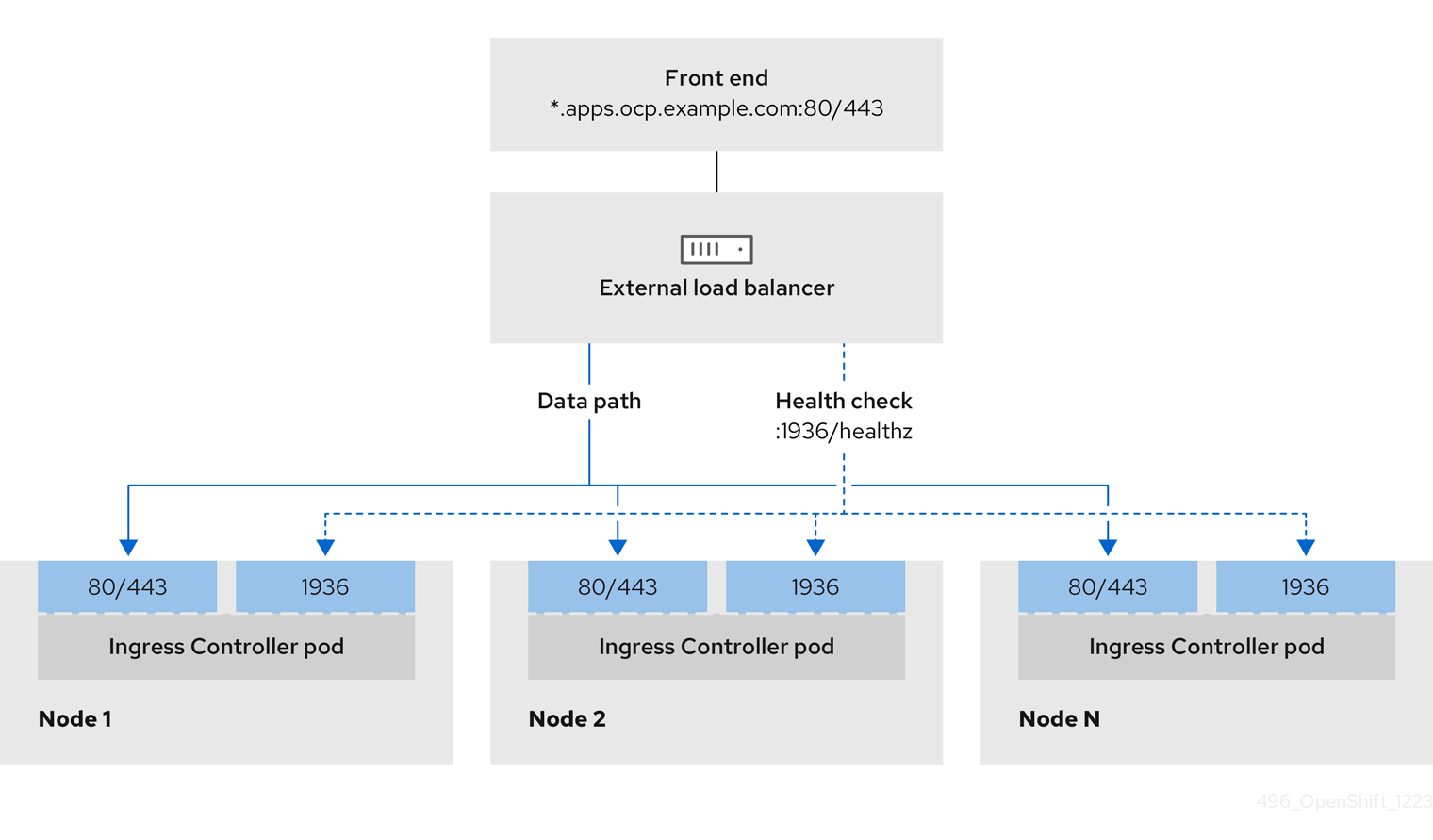
Figure 3.2. Example network workflow that shows an OpenShift API operating in an OpenShift Container Platform environment
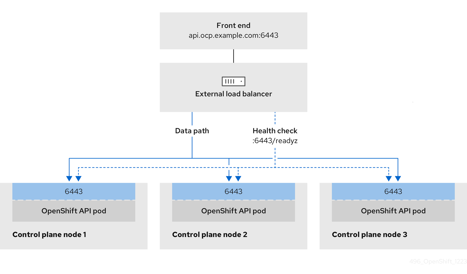
Figure 3.3. Example network workflow that shows an OpenShift MachineConfig API operating in an OpenShift Container Platform environment

The following configuration options are supported for user-managed load balancers:
- Use a node selector to map the Ingress Controller to a specific set of nodes. You must assign a static IP address to each node in this set, or configure each node to receive the same IP address from the Dynamic Host Configuration Protocol (DHCP). Infrastructure nodes commonly receive this type of configuration.
Target all IP addresses on a subnet. This configuration can reduce maintenance overhead, because you can create and destroy nodes within those networks without reconfiguring the load balancer targets. If you deploy your ingress pods by using a machine set on a smaller network, such as a
/27or/28, you can simplify your load balancer targets.TipYou can list all IP addresses that exist in a network by checking the machine config pool’s resources.
Before you configure a user-managed load balancer for your OpenShift Container Platform cluster, consider the following information:
- For a front-end IP address, you can use the same IP address for the front-end IP address, the Ingress Controller’s load balancer, and API load balancer. Check the vendor’s documentation for this capability.
For a back-end IP address, ensure that an IP address for an OpenShift Container Platform control plane node does not change during the lifetime of the user-managed load balancer. You can achieve this by completing one of the following actions:
- Assign a static IP address to each control plane node.
- Configure each node to receive the same IP address from the DHCP every time the node requests a DHCP lease. Depending on the vendor, the DHCP lease might be in the form of an IP reservation or a static DHCP assignment.
- Manually define each node that runs the Ingress Controller in the user-managed load balancer for the Ingress Controller back-end service. For example, if the Ingress Controller moves to an undefined node, a connection outage can occur.
3.3.10.1. Configuring a user-managed load balancer
To integrate your infrastructure with existing network standards or gain more control over traffic management in OpenShift Container Platform , use a user-managed load balancer in place of the default load balancer.
Before you configure a user-managed load balancer, ensure that you read the "Services for a user-managed load balancer" section.
Read the following prerequisites that apply to the service that you want to configure for your user-managed load balancer.
MetalLB, which runs on a cluster, functions as a user-managed load balancer.
Prerequisites
The following list details OpenShift API prerequisites:
- You defined a front-end IP address.
TCP ports 6443 and 22623 are exposed on the front-end IP address of your load balancer. Check the following items:
- Port 6443 provides access to the OpenShift API service.
- Port 22623 can provide ignition startup configurations to nodes.
- The front-end IP address and port 6443 are reachable by all users of your system with a location external to your OpenShift Container Platform cluster.
- The front-end IP address and port 22623 are reachable only by OpenShift Container Platform nodes.
- The load balancer backend can communicate with OpenShift Container Platform control plane nodes on port 6443 and 22623.
The following list details Ingress Controller prerequisites:
- You defined a front-end IP address.
- TCP port 443 and port 80 are exposed on the front-end IP address of your load balancer.
- The front-end IP address, port 80 and port 443 are reachable by all users of your system with a location external to your OpenShift Container Platform cluster.
- The front-end IP address, port 80 and port 443 are reachable by all nodes that operate in your OpenShift Container Platform cluster.
- The load balancer backend can communicate with OpenShift Container Platform nodes that run the Ingress Controller on ports 80, 443, and 1936.
The following list details prerequisites for health check URL specifications:
You can configure most load balancers by setting health check URLs that determine if a service is available or unavailable. OpenShift Container Platform provides these health checks for the OpenShift API, Machine Configuration API, and Ingress Controller backend services.
The following example shows a Kubernetes API health check specification for a backend service:
Path: HTTPS:6443/readyz
Healthy threshold: 2
Unhealthy threshold: 2
Timeout: 10
Interval: 10The following example shows a Machine Config API health check specification for a backend service:
Path: HTTPS:22623/healthz
Healthy threshold: 2
Unhealthy threshold: 2
Timeout: 10
Interval: 10The following example shows a Ingress Controller health check specification for a backend service:
Path: HTTP:1936/healthz/ready
Healthy threshold: 2
Unhealthy threshold: 2
Timeout: 5
Interval: 10Procedure
Configure the HAProxy Ingress Controller, so that you can enable access to the cluster from your load balancer on ports 6443, 22623, 443, and 80. Depending on your needs, you can specify the IP address of a single subnet or IP addresses from multiple subnets in your HAProxy configuration.
Example HAProxy configuration with one listed subnet
# ... listen my-cluster-api-6443 bind 192.168.1.100:6443 mode tcp balance roundrobin option httpchk http-check connect http-check send meth GET uri /readyz http-check expect status 200 server my-cluster-master-2 192.168.1.101:6443 check inter 10s rise 2 fall 2 server my-cluster-master-0 192.168.1.102:6443 check inter 10s rise 2 fall 2 server my-cluster-master-1 192.168.1.103:6443 check inter 10s rise 2 fall 2 listen my-cluster-machine-config-api-22623 bind 192.168.1.100:22623 mode tcp balance roundrobin option httpchk http-check connect http-check send meth GET uri /healthz http-check expect status 200 server my-cluster-master-2 192.168.1.101:22623 check inter 10s rise 2 fall 2 server my-cluster-master-0 192.168.1.102:22623 check inter 10s rise 2 fall 2 server my-cluster-master-1 192.168.1.103:22623 check inter 10s rise 2 fall 2 listen my-cluster-apps-443 bind 192.168.1.100:443 mode tcp balance roundrobin option httpchk http-check connect http-check send meth GET uri /healthz/ready http-check expect status 200 server my-cluster-worker-0 192.168.1.111:443 check port 1936 inter 10s rise 2 fall 2 server my-cluster-worker-1 192.168.1.112:443 check port 1936 inter 10s rise 2 fall 2 server my-cluster-worker-2 192.168.1.113:443 check port 1936 inter 10s rise 2 fall 2 listen my-cluster-apps-80 bind 192.168.1.100:80 mode tcp balance roundrobin option httpchk http-check connect http-check send meth GET uri /healthz/ready http-check expect status 200 server my-cluster-worker-0 192.168.1.111:80 check port 1936 inter 10s rise 2 fall 2 server my-cluster-worker-1 192.168.1.112:80 check port 1936 inter 10s rise 2 fall 2 server my-cluster-worker-2 192.168.1.113:80 check port 1936 inter 10s rise 2 fall 2 # ...Example HAProxy configuration with multiple listed subnets
# ... listen api-server-6443 bind *:6443 mode tcp server master-00 192.168.83.89:6443 check inter 1s server master-01 192.168.84.90:6443 check inter 1s server master-02 192.168.85.99:6443 check inter 1s server bootstrap 192.168.80.89:6443 check inter 1s listen machine-config-server-22623 bind *:22623 mode tcp server master-00 192.168.83.89:22623 check inter 1s server master-01 192.168.84.90:22623 check inter 1s server master-02 192.168.85.99:22623 check inter 1s server bootstrap 192.168.80.89:22623 check inter 1s listen ingress-router-80 bind *:80 mode tcp balance source server worker-00 192.168.83.100:80 check inter 1s server worker-01 192.168.83.101:80 check inter 1s listen ingress-router-443 bind *:443 mode tcp balance source server worker-00 192.168.83.100:443 check inter 1s server worker-01 192.168.83.101:443 check inter 1s listen ironic-api-6385 bind *:6385 mode tcp balance source server master-00 192.168.83.89:6385 check inter 1s server master-01 192.168.84.90:6385 check inter 1s server master-02 192.168.85.99:6385 check inter 1s server bootstrap 192.168.80.89:6385 check inter 1s listen inspector-api-5050 bind *:5050 mode tcp balance source server master-00 192.168.83.89:5050 check inter 1s server master-01 192.168.84.90:5050 check inter 1s server master-02 192.168.85.99:5050 check inter 1s server bootstrap 192.168.80.89:5050 check inter 1s # ...Use the
curlCLI command to verify that the user-managed load balancer and its resources are operational:Verify that the cluster machine configuration API is accessible to the Kubernetes API server resource, by running the following command and observing the response:
$ curl https://<loadbalancer_ip_address>:6443/version --insecureIf the configuration is correct, you receive a JSON object in response:
{ "major": "1", "minor": "11+", "gitVersion": "v1.11.0+ad103ed", "gitCommit": "ad103ed", "gitTreeState": "clean", "buildDate": "2019-01-09T06:44:10Z", "goVersion": "go1.10.3", "compiler": "gc", "platform": "linux/amd64" }Verify that the cluster machine configuration API is accessible to the Machine config server resource, by running the following command and observing the output:
$ curl -v https://<loadbalancer_ip_address>:22623/healthz --insecureIf the configuration is correct, the output from the command shows the following response:
HTTP/1.1 200 OK Content-Length: 0Verify that the controller is accessible to the Ingress Controller resource on port 80, by running the following command and observing the output:
$ curl -I -L -H "Host: console-openshift-console.apps.<cluster_name>.<base_domain>" http://<load_balancer_front_end_IP_address>If the configuration is correct, the output from the command shows the following response:
HTTP/1.1 302 Found content-length: 0 location: https://console-openshift-console.apps.ocp4.private.opequon.net/ cache-control: no-cacheVerify that the controller is accessible to the Ingress Controller resource on port 443, by running the following command and observing the output:
$ curl -I -L --insecure --resolve console-openshift-console.apps.<cluster_name>.<base_domain>:443:<Load Balancer Front End IP Address> https://console-openshift-console.apps.<cluster_name>.<base_domain>If the configuration is correct, the output from the command shows the following response:
HTTP/1.1 200 OK referrer-policy: strict-origin-when-cross-origin set-cookie: csrf-token=UlYWOyQ62LWjw2h003xtYSKlh1a0Py2hhctw0WmV2YEdhJjFyQwWcGBsja261dGLgaYO0nxzVErhiXt6QepA7g==; Path=/; Secure; SameSite=Lax x-content-type-options: nosniff x-dns-prefetch-control: off x-frame-options: DENY x-xss-protection: 1; mode=block date: Wed, 04 Oct 2023 16:29:38 GMT content-type: text/html; charset=utf-8 set-cookie: 1e2670d92730b515ce3a1bb65da45062=1bf5e9573c9a2760c964ed1659cc1673; path=/; HttpOnly; Secure; SameSite=None cache-control: private
Configure the DNS records for your cluster to target the front-end IP addresses of the user-managed load balancer. You must update records to your DNS server for the cluster API and applications over the load balancer. The following examples shows modified DNS records:
<load_balancer_ip_address> A api.<cluster_name>.<base_domain> A record pointing to Load Balancer Front End<load_balancer_ip_address> A apps.<cluster_name>.<base_domain> A record pointing to Load Balancer Front EndImportantDNS propagation might take some time for each DNS record to become available. Ensure that each DNS record propagates before validating each record.
For your OpenShift Container Platform cluster to use the user-managed load balancer, you must specify the following configuration in your cluster’s
install-config.yamlfile:# ... platform: baremetal: loadBalancer: type: UserManaged apiVIPs: - <api_ip>1 ingressVIPs: - <ingress_ip>2 # ...where:
loadBalancer.type-
Set
UserManagedfor thetypeparameter to specify a user-managed load balancer for your cluster. The parameter defaults toOpenShiftManagedDefault, which denotes the default internal load balancer. For services defined in anopenshift-kni-infranamespace, a user-managed load balancer can deploy thecorednsservice to pods in your cluster but ignoreskeepalivedandhaproxyservices. loadBalancer.<api_ip>- Specifies a user-managed load balancer. Specify the user-managed load balancer’s public IP address, so that the Kubernetes API can communicate with the user-managed load balancer. Mandatory parameter.
loadBalancer.<ingress_ip>- Specifies a user-managed load balancer. Specify the user-managed load balancer’s public IP address, so that the user-managed load balancer can manage ingress traffic for your cluster. Mandatory parameter.
Verification
Use the
curlCLI command to verify that the user-managed load balancer and DNS record configuration are operational:Verify that you can access the cluster API, by running the following command and observing the output:
$ curl https://api.<cluster_name>.<base_domain>:6443/version --insecureIf the configuration is correct, you receive a JSON object in response:
{ "major": "1", "minor": "11+", "gitVersion": "v1.11.0+ad103ed", "gitCommit": "ad103ed", "gitTreeState": "clean", "buildDate": "2019-01-09T06:44:10Z", "goVersion": "go1.10.3", "compiler": "gc", "platform": "linux/amd64" }Verify that you can access the cluster machine configuration, by running the following command and observing the output:
$ curl -v https://api.<cluster_name>.<base_domain>:22623/healthz --insecureIf the configuration is correct, the output from the command shows the following response:
HTTP/1.1 200 OK Content-Length: 0Verify that you can access each cluster application on port 80, by running the following command and observing the output:
$ curl http://console-openshift-console.apps.<cluster_name>.<base_domain> -I -L --insecureIf the configuration is correct, the output from the command shows the following response:
HTTP/1.1 302 Found content-length: 0 location: https://console-openshift-console.apps.<cluster-name>.<base domain>/ cache-control: no-cacheHTTP/1.1 200 OK referrer-policy: strict-origin-when-cross-origin set-cookie: csrf-token=39HoZgztDnzjJkq/JuLJMeoKNXlfiVv2YgZc09c3TBOBU4NI6kDXaJH1LdicNhN1UsQWzon4Dor9GWGfopaTEQ==; Path=/; Secure x-content-type-options: nosniff x-dns-prefetch-control: off x-frame-options: DENY x-xss-protection: 1; mode=block date: Tue, 17 Nov 2020 08:42:10 GMT content-type: text/html; charset=utf-8 set-cookie: 1e2670d92730b515ce3a1bb65da45062=9b714eb87e93cf34853e87a92d6894be; path=/; HttpOnly; Secure; SameSite=None cache-control: privateVerify that you can access each cluster application on port 443, by running the following command and observing the output:
$ curl https://console-openshift-console.apps.<cluster_name>.<base_domain> -I -L --insecureIf the configuration is correct, the output from the command shows the following response:
HTTP/1.1 200 OK referrer-policy: strict-origin-when-cross-origin set-cookie: csrf-token=UlYWOyQ62LWjw2h003xtYSKlh1a0Py2hhctw0WmV2YEdhJjFyQwWcGBsja261dGLgaYO0nxzVErhiXt6QepA7g==; Path=/; Secure; SameSite=Lax x-content-type-options: nosniff x-dns-prefetch-control: off x-frame-options: DENY x-xss-protection: 1; mode=block date: Wed, 04 Oct 2023 16:29:38 GMT content-type: text/html; charset=utf-8 set-cookie: 1e2670d92730b515ce3a1bb65da45062=1bf5e9573c9a2760c964ed1659cc1673; path=/; HttpOnly; Secure; SameSite=None cache-control: private
3.3.11. Setting the cluster node hostnames through DHCP
On Red Hat Enterprise Linux CoreOS (RHCOS) machines, NetworkManager sets the hostnames. By default, DHCP provides the hostnames to NetworkManager, which is the recommended method. NetworkManager gets the hostnames through a reverse DNS lookup in the following cases:
- If DHCP does not provide the hostnames
- If you use kernel arguments to set the hostnames
- If you use another method to set the hostnames
Reverse DNS lookup occurs after the network has been initialized on a node, and can increase the time it takes NetworkManager to set the hostname. Other system services can start prior to NetworkManager setting the hostname, which can cause those services to use a default hostname such as localhost.
You can avoid the delay in setting hostnames by using DHCP to provide the hostname for each cluster node. Additionally, setting the hostnames through DHCP can bypass manual DNS record name configuration errors in environments that have a DNS split-horizon implementation.
3.3.12. Configuring the install-config.yaml file
3.3.12.1. Configuring the install-config.yaml file
The install-config.yaml file requires some additional details. Most of the information teaches the installation program and the resulting cluster enough about the available hardware that it is able to fully manage it.
The installation program no longer needs the clusterOSImage RHCOS image because the correct image is in the release payload.
Configure
install-config.yaml. Change the appropriate variables to match the environment, includingpullSecretandsshKey:apiVersion: v1 baseDomain: <domain> metadata: name: <cluster_name> networking: machineNetwork: - cidr: <public_cidr> networkType: OVNKubernetes compute: - name: worker replicas: 21 controlPlane: name: master replicas: 3 platform: baremetal: {} platform: baremetal: additionalNTPServers:2 - <ntp_domain_or_ip> apiVIPs: - <api_ip> ingressVIPs: - <wildcard_ip> provisioningNetworkCIDR: <CIDR> bootstrapExternalStaticIP: <bootstrap_static_ip_address>3 bootstrapExternalStaticGateway: <bootstrap_static_gateway>4 bootstrapExternalStaticDNS: <bootstrap_static_dns>5 hosts: - name: openshift-master-0 role: master bmc: address: ipmi://<out_of_band_ip>6 username: <user> password: <password> bootMACAddress: <NIC1_mac_address> rootDeviceHints: deviceName: "<installation_disk_drive_path>"7 - name: <openshift_master_1> role: master bmc: address: ipmi://<out_of_band_ip> username: <user> password: <password> bootMACAddress: <NIC1_mac_address> rootDeviceHints: deviceName: "<installation_disk_drive_path>" - name: <openshift_master_2> role: master bmc: address: ipmi://<out_of_band_ip> username: <user> password: <password> bootMACAddress: <NIC1_mac_address> rootDeviceHints: deviceName: "<installation_disk_drive_path>" - name: <openshift_worker_0> role: worker bmc: address: ipmi://<out_of_band_ip> username: <user> password: <password> bootMACAddress: <NIC1_mac_address> - name: <openshift_worker_1> role: worker bmc: address: ipmi://<out_of_band_ip> username: <user> password: <password> bootMACAddress: <NIC1_mac_address> rootDeviceHints: deviceName: "<installation_disk_drive_path>" pullSecret: '<pull_secret>' sshKey: '<ssh_pub_key>'- 1
- Scale the compute machines based on the number of compute nodes that are part of the OpenShift Container Platform cluster. Valid options for the
replicasvalue are0and integers greater than or equal to2. Set the number of replicas to0to deploy a three-node cluster, which contains only three control plane machines. A three-node cluster is a smaller, more resource-efficient cluster that can be used for testing, development, and production. You cannot install the cluster with only one compute node. - 1 2
- An optional list of additional NTP server domain names or IP addresses to add to each host configuration when the cluster host clocks are out of synchronization.
- 2 3
- When deploying a cluster with static IP addresses, you must set the
bootstrapExternalStaticIPconfiguration setting to specify the static IP address of the bootstrap VM when there is no DHCP server on the bare metal network. - 4
- When deploying a cluster with static IP addresses, you must set the
bootstrapExternalStaticGatewayconfiguration setting to specify the gateway IP address for the bootstrap VM when there is no DHCP server on the bare metal network. - 5
- When deploying a cluster with static IP addresses, you must set the
bootstrapExternalStaticDNSconfiguration setting to specify the DNS address for the bootstrap VM when there is no DHCP server on the bare metal network. - 6
- See the BMC addressing sections for more options.
- 7
- To set the path to the installation disk drive, enter the kernel name of the disk. For example,
/dev/sda.ImportantBecause the disk discovery order is not guaranteed, the kernel name of the disk can change across booting options for machines with multiple disks. For example,
/dev/sdabecomes/dev/sdband vice versa. To avoid this issue, you must use persistent disk attributes, such as the disk World Wide Name (WWN) or/dev/disk/by-path/. It is recommended to use the/dev/disk/by-path/<device_path>link to the storage location. To use the disk WWN, replace thedeviceNameparameter with thewwnWithExtensionparameter. Depending on the parameter that you use, enter either of the following values:-
The disk name. For example,
/dev/sda, or/dev/disk/by-path/. -
The disk WWN. For example,
"0x64cd98f04fde100024684cf3034da5c2". Ensure that you enter the disk WWN value within quotes so that it is used as a string value and not a hexadecimal value.
Failure to meet these requirements for the
rootDeviceHintsparameter might result in the following error:ironic-inspector inspection failed: No disks satisfied root device hints -
The disk name. For example,
NoteBefore OpenShift Container Platform 4.12, the cluster installation program only accepted an IPv4 address or an IPv6 address for the
apiVIPandingressVIPconfiguration settings. In OpenShift Container Platform 4.12 and later, these configuration settings are deprecated. Instead, use a list format in theapiVIPsandingressVIPsconfiguration settings to specify IPv4 addresses, IPv6 addresses, or both IP address formats.Create a directory to store the cluster configuration:
$ mkdir ~/clusterconfigsCopy the
install-config.yamlfile to the new directory:$ cp install-config.yaml ~/clusterconfigsEnsure all bare metal nodes are powered off prior to installing the OpenShift Container Platform cluster:
$ ipmitool -I lanplus -U <user> -P <password> -H <management-server-ip> power offRemove old bootstrap resources if any are left over from a previous deployment attempt:
for i in $(sudo virsh list | tail -n +3 | grep bootstrap | awk {'print $2'}); do sudo virsh destroy $i; sudo virsh undefine $i; sudo virsh vol-delete $i --pool $i; sudo virsh vol-delete $i.ign --pool $i; sudo virsh pool-destroy $i; sudo virsh pool-undefine $i; done
3.3.12.2. Additional install-config parameters
See the following tables for the required parameters, the hosts parameter, and the bmc parameter for the install-config.yaml file.
| Parameters | Default | Description |
|---|---|---|
|
|
The domain name for the cluster. For example, | |
|
|
|
The boot mode for a node. Options are Note
For hardware that implements |
|
The static network DNS of the bootstrap node. You must set this value when deploying a cluster with static IP addresses when there is no Dynamic Host Configuration Protocol (DHCP) server on the bare-metal network. If you do not set this value, the installation program will use the value from | |
| The static IP address for the bootstrap VM. You must set this value when deploying a cluster with static IP addresses when there is no DHCP server on the bare-metal network. | |
| The static IP address of the gateway for the bootstrap VM. You must set this value when deploying a cluster with static IP addresses when there is no DHCP server on the bare-metal network. | |
|
|
The | |
|
|
The | |
|
The name of the OpenShift Container Platform cluster. For example, | |
|
The public CIDR (Classless Inter-Domain Routing) of the external network. For example, | |
| The OpenShift Container Platform cluster requires you to provide a name for compute nodes even if there are zero nodes. | |
| Replicas sets the number of compute nodes in the OpenShift Container Platform cluster. | |
| The OpenShift Container Platform cluster requires a name for control plane nodes. | |
| Replicas sets the number of control plane nodes included as part of the OpenShift Container Platform cluster. | |
|
|
The name of the network interface on nodes connected to the provisioning network. For OpenShift Container Platform 4.9 and later releases, use the | |
|
| The default configuration used for machine pools without a platform configuration. | |
|
| (Optional) The virtual IP address for Kubernetes API communication.
You must either provide this setting in the Note
Before OpenShift Container Platform 4.12, the cluster installation program only accepted an IPv4 address or an IPv6 address for the | |
|
|
|
|
|
| (Optional) The virtual IP address for ingress traffic.
You must either provide this setting in the Note
Before OpenShift Container Platform 4.12, the cluster installation program only accepted an IPv4 address or an IPv6 address for the |
| Parameters | Default | Description |
|---|---|---|
| An optional list of additional NTP servers to add to each host. You can use an IP address or a domain name to specify each NTP server. Additional NTP servers are user-defined NTP servers that enable preinstallation clock synchronization when the cluster host clocks are out of synchronization. | |
|
|
| Defines the IP range for nodes on the provisioning network. |
|
|
| The CIDR for the network to use for provisioning. The installation program requires this option when not using the default address range on the provisioning network. |
|
|
The third IP address of the |
The IP address within the cluster where the provisioning services run. Defaults to the third IP address of the provisioning subnet. For example, |
|
|
The second IP address of the |
The IP address on the bootstrap VM where the provisioning services run while the installation program is deploying the control plane (master) nodes. Defaults to the second IP address of the provisioning subnet. For example, |
|
|
| The name of the bare-metal bridge of the hypervisor attached to the bare-metal network. |
|
|
|
The name of the provisioning bridge on the |
|
|
Defines the host architecture for your cluster. Valid values are | |
|
| The default configuration used for machine pools without a platform configuration. | |
|
|
A URL to override the default operating system image for the bootstrap node. The URL must contain a SHA-256 hash of the image. For example: | |
|
|
The
| |
|
| Set this parameter to the appropriate HTTP proxy used within your environment. | |
|
| Set this parameter to the appropriate HTTPS proxy used within your environment. | |
|
| Set this parameter to the appropriate list of exclusions for proxy usage within your environment. |
3.3.12.2.1. Hosts
The hosts parameter is a list of separate bare metal assets used to build the cluster.
| Name | Default | Description |
|---|---|---|
|
|
The name of the | |
|
|
The role of the bare-metal node. Either | |
|
| Connection details for the baseboard management controller. See the BMC addressing section for additional details. | |
|
|
The MAC address of the NIC that the host uses for the provisioning network. Ironic retrieves the IP address using the Note You must provide a valid MAC address from the host if you disabled the provisioning network. | |
|
| Set this optional parameter to configure the network interface of a host. See "(Optional) Configuring host network interfaces" for additional details. |
3.3.12.3. BMC addressing
Most vendors support Baseboard Management Controller (BMC) addressing with the Intelligent Platform Management Interface (IPMI). IPMI does not encrypt communications. It is suitable for use within a data center over a secured or dedicated management network. Check with your vendor to see if they support Redfish network boot. Redfish delivers simple and secure management for converged, hybrid IT and the Software Defined Data Center (SDDC). Redfish is human readable and machine capable, and leverages common internet and web services standards to expose information directly to the modern tool chain. If your hardware does not support Redfish network boot, use IPMI.
You can modify the BMC address during installation while the node is in the Registering state. If you need to modify the BMC address after the node leaves the Registering state, you must disconnect the node from Ironic, edit the BareMetalHost resource, and reconnect the node to Ironic. See the Editing a BareMetalHost resource section for details.
3.3.12.3.1. IPMI
Hosts using IPMI use the ipmi://<out-of-band-ip>:<port> address format, which defaults to port 623 if not specified. The following example demonstrates an IPMI configuration within the install-config.yaml file.
platform:
baremetal:
hosts:
- name: openshift-master-0
role: master
bmc:
address: ipmi://<out-of-band-ip>
username: <user>
password: <password>
The provisioning network is required when PXE booting using IPMI for BMC addressing. It is not possible to PXE boot hosts without a provisioning network. If you deploy without a provisioning network, you must use a virtual media BMC addressing option such as redfish-virtualmedia or idrac-virtualmedia. See "Redfish virtual media for HPE iLO" in the "BMC addressing for HPE iLO" section or "Redfish virtual media for Dell iDRAC" in the "BMC addressing for Dell iDRAC" section for additional details.
3.3.12.3.2. Redfish network boot
To enable Redfish, use redfish:// or redfish+http:// to disable TLS. The installer requires both the hostname or the IP address and the path to the system ID. The following example demonstrates a Redfish configuration within the install-config.yaml file.
platform:
baremetal:
hosts:
- name: openshift-master-0
role: master
bmc:
address: redfish://<out-of-band-ip>/redfish/v1/Systems/1
username: <user>
password: <password>
While it is recommended to have a certificate of authority for the out-of-band management addresses, you must include disableCertificateVerification: True in the bmc configuration if using self-signed certificates. The following example demonstrates a Redfish configuration using the disableCertificateVerification: True configuration parameter within the install-config.yaml file.
platform:
baremetal:
hosts:
- name: openshift-master-0
role: master
bmc:
address: redfish://<out-of-band-ip>/redfish/v1/Systems/1
username: <user>
password: <password>
disableCertificateVerification: True3.3.12.4. Verifying support for Redfish APIs
When installing using the Redfish API, the installation program calls several Redfish endpoints on the baseboard management controller (BMC) when using installer-provisioned infrastructure on bare metal. If you use Redfish, ensure that your BMC supports all of the Redfish APIs before installation.
Procedure
Set the IP address or hostname of the BMC by running the following command:
$ export SERVER=<ip_address>1 - 1
- Replace
<ip_address>with the IP address or hostname of the BMC.
Set the ID of the system by running the following command:
$ export SystemID=<system_id>1 - 1
- Replace
<system_id>with the system ID. For example,System.Embedded.1or1. See the following vendor-specific BMC sections for details.
List of Redfish APIs
Check
power onsupport by running the following command:$ curl -u $USER:$PASS -X POST -H'Content-Type: application/json' -H'Accept: application/json' -d '{"ResetType": "On"}' https://$SERVER/redfish/v1/Systems/$SystemID/Actions/ComputerSystem.ResetCheck
power offsupport by running the following command:$ curl -u $USER:$PASS -X POST -H'Content-Type: application/json' -H'Accept: application/json' -d '{"ResetType": "ForceOff"}' https://$SERVER/redfish/v1/Systems/$SystemID/Actions/ComputerSystem.ResetCheck the temporary boot implementation that uses
pxeby running the following command:$ curl -u $USER:$PASS -X PATCH -H "Content-Type: application/json" -H "If-Match: <ETAG>" https://$Server/redfish/v1/Systems/$SystemID/ -d '{"Boot": {"BootSourceOverrideTarget": "pxe", "BootSourceOverrideEnabled": "Once"}}Check the status of setting the firmware boot mode that uses
LegacyorUEFIby running the following command:$ curl -u $USER:$PASS -X PATCH -H "Content-Type: application/json" -H "If-Match: <ETAG>" https://$Server/redfish/v1/Systems/$SystemID/ -d '{"Boot": {"BootSourceOverrideMode":"UEFI"}}
List of Redfish virtual media APIs
Check the ability to set the temporary boot device that uses
cdordvdby running the following command:$ curl -u $USER:$PASS -X PATCH -H "Content-Type: application/json" -H "If-Match: <ETAG>" https://$Server/redfish/v1/Systems/$SystemID/ -d '{"Boot": {"BootSourceOverrideTarget": "cd", "BootSourceOverrideEnabled": "Once"}}'Virtual media might use
POSTorPATCH, depending on your hardware. Check the ability to mount virtual media by running one of the following commands:$ curl -u $USER:$PASS -X POST -H "Content-Type: application/json" https://$Server/redfish/v1/Managers/$ManagerID/VirtualMedia/$VmediaId -d '{"Image": "https://example.com/test.iso", "TransferProtocolType": "HTTPS", "UserName": "", "Password":""}'$ curl -u $USER:$PASS -X PATCH -H "Content-Type: application/json" -H "If-Match: <ETAG>" https://$Server/redfish/v1/Managers/$ManagerID/VirtualMedia/$VmediaId -d '{"Image": "https://example.com/test.iso", "TransferProtocolType": "HTTPS", "UserName": "", "Password":""}'
The PowerOn and PowerOff commands for Redfish APIs are the same for the Redfish virtual media APIs. In some hardware, you might only find the VirtualMedia resource under Systems/$SystemID instead of Managers/$ManagerID. For the VirtualMedia resource, the UserName and Password fields are optional.
HTTPS and HTTP are the only supported parameter types for TransferProtocolTypes.
3.3.12.5. BMC addressing for Dell iDRAC
The address configuration setting for each bmc entry is a URL for connecting to the OpenShift Container Platform cluster nodes, including the type of controller in the URL scheme and its location on the network. The username configuration for each bmc entry must specify a user with Administrator privileges.
platform:
baremetal:
hosts:
- name: <hostname>
role: <master | worker>
bmc:
address: <address>
username: <user>
password: <password>For Dell hardware, Red Hat supports integrated Dell Remote Access Controller (iDRAC) virtual media, Redfish network boot, and IPMI.
3.3.12.5.1. BMC address formats for Dell iDRAC
| Protocol | Address Format |
|---|---|
| iDRAC virtual media |
|
| Redfish network boot |
|
| IPMI |
|
Use idrac-virtualmedia as the protocol for Redfish virtual media. redfish-virtualmedia will not work on Dell hardware. Dell’s idrac-virtualmedia uses the Redfish standard with Dell’s OEM extensions.
See the following sections for additional details.
3.3.12.5.2. Redfish virtual media for Dell iDRAC
For Redfish virtual media on Dell servers, use idrac-virtualmedia:// in the address setting. Using redfish-virtualmedia:// will not work.
Use idrac-virtualmedia:// as the protocol for Redfish virtual media. Using redfish-virtualmedia:// will not work on Dell hardware, because the idrac-virtualmedia:// protocol corresponds to the idrac hardware type and the Redfish protocol in Ironic. Dell’s idrac-virtualmedia:// protocol uses the Redfish standard with Dell’s OEM extensions. Ironic also supports the idrac type with the WSMAN protocol. Therefore, you must specify idrac-virtualmedia:// to avoid unexpected behavior when electing to use Redfish with virtual media on Dell hardware.
The following example demonstrates using iDRAC virtual media within the install-config.yaml file.
platform:
baremetal:
hosts:
- name: openshift-master-0
role: master
bmc:
address: idrac-virtualmedia://<out_of_band_ip>/redfish/v1/Systems/System.Embedded.1
username: <user>
password: <password>
While it is recommended to have a certificate of authority for the out-of-band management addresses, you must include disableCertificateVerification: True in the bmc configuration if using self-signed certificates.
Ensure the OpenShift Container Platform cluster nodes have AutoAttach enabled through the iDRAC console. The menu path is: Configuration → Virtual Media → Attach Mode → AutoAttach.
The following example demonstrates a Redfish configuration that uses the disableCertificateVerification: True configuration parameter within the install-config.yaml file.
platform:
baremetal:
hosts:
- name: openshift-master-0
role: master
bmc:
address: idrac-virtualmedia://<out_of_band_ip>/redfish/v1/Systems/System.Embedded.1
username: <user>
password: <password>
disableCertificateVerification: True3.3.12.5.3. Redfish network boot for iDRAC
To enable Redfish, use redfish:// or redfish+http:// to disable transport layer security (TLS). The installation program requires both the hostname or the IP address and the path to the system ID. The following example demonstrates a Redfish configuration within the install-config.yaml file.
platform:
baremetal:
hosts:
- name: openshift-master-0
role: master
bmc:
address: redfish://<out_of_band_ip>/redfish/v1/Systems/System.Embedded.1
username: <user>
password: <password>
While it is recommended to have a certificate of authority for the out-of-band management addresses, you must include disableCertificateVerification: True in the bmc configuration if you use self-signed certificates. The following example demonstrates a Redfish configuration that uses the disableCertificateVerification: True configuration parameter within the install-config.yaml file.
platform:
baremetal:
hosts:
- name: openshift-master-0
role: master
bmc:
address: redfish://<out_of_band_ip>/redfish/v1/Systems/System.Embedded.1
username: <user>
password: <password>
disableCertificateVerification: True
There is a known issue on Dell iDRAC 9 with firmware version 04.40.00.00 and all releases up to including the 5.xx series for installer-provisioned installations on bare metal deployments. The virtual console plugin defaults to eHTML5, an enhanced version of HTML5, which causes problems with the InsertVirtualMedia workflow. Set the plugin to use HTML5 to avoid this issue. The menu path is Configuration → Virtual console → Plug-in Type → HTML5 .
Ensure the OpenShift Container Platform cluster nodes have AutoAttach enabled through the iDRAC console. The menu path is: Configuration → Virtual Media → Attach Mode → AutoAttach .
3.3.12.6. BMC addressing for HPE iLO
The address field for each bmc entry is a URL for connecting to the OpenShift Container Platform cluster nodes, including the type of controller in the URL scheme and its location on the network.
platform:
baremetal:
hosts:
- name: <hostname>
role: <master | worker>
bmc:
address: <address>
username: <user>
password: <password>- 1
- The
addressconfiguration setting specifies the protocol.
For HPE integrated Lights Out (iLO), Red Hat supports Redfish virtual media, Redfish network boot, and IPMI.
| Protocol | Address Format |
|---|---|
| Redfish virtual media |
|
| Redfish network boot |
|
| IPMI |
|
See the following sections for additional details.
3.3.12.6.1. Redfish virtual media for HPE iLO
To enable Redfish virtual media for HPE servers, use redfish-virtualmedia:// in the address setting. The following example demonstrates using Redfish virtual media within the install-config.yaml file.
platform:
baremetal:
hosts:
- name: openshift-master-0
role: master
bmc:
address: redfish-virtualmedia://<out-of-band-ip>/redfish/v1/Systems/1
username: <user>
password: <password>
While it is recommended to have a certificate of authority for the out-of-band management addresses, you must include disableCertificateVerification: True in the bmc configuration if using self-signed certificates. The following example demonstrates a Redfish configuration using the disableCertificateVerification: True configuration parameter within the install-config.yaml file.
platform:
baremetal:
hosts:
- name: openshift-master-0
role: master
bmc:
address: redfish-virtualmedia://<out-of-band-ip>/redfish/v1/Systems/1
username: <user>
password: <password>
disableCertificateVerification: TrueRedfish virtual media is not supported on 9th generation systems running iLO4, because Ironic does not support iLO4 with virtual media.
3.3.12.6.2. Redfish network boot for HPE iLO
To enable Redfish, use redfish:// or redfish+http:// to disable TLS. The installer requires both the hostname or the IP address and the path to the system ID. The following example demonstrates a Redfish configuration within the install-config.yaml file.
platform:
baremetal:
hosts:
- name: openshift-master-0
role: master
bmc:
address: redfish://<out-of-band-ip>/redfish/v1/Systems/1
username: <user>
password: <password>
While it is recommended to have a certificate of authority for the out-of-band management addresses, you must include disableCertificateVerification: True in the bmc configuration if using self-signed certificates. The following example demonstrates a Redfish configuration using the disableCertificateVerification: True configuration parameter within the install-config.yaml file.
platform:
baremetal:
hosts:
- name: openshift-master-0
role: master
bmc:
address: redfish://<out-of-band-ip>/redfish/v1/Systems/1
username: <user>
password: <password>
disableCertificateVerification: True3.3.12.7. BMC addressing for Fujitsu iRMC
The address field for each bmc entry is a URL for connecting to the OpenShift Container Platform cluster nodes, including the type of controller in the URL scheme and its location on the network.
platform:
baremetal:
hosts:
- name: <hostname>
role: <master | worker>
bmc:
address: <address>
username: <user>
password: <password>- 1
- The
addressconfiguration setting specifies the protocol.
For Fujitsu hardware, Red Hat supports integrated Remote Management Controller (iRMC) and IPMI.
| Protocol | Address Format |
|---|---|
| iRMC |
|
| IPMI |
|
iRMC
Fujitsu nodes can use irmc://<out-of-band-ip> and defaults to port 443. The following example demonstrates an iRMC configuration within the install-config.yaml file.
platform:
baremetal:
hosts:
- name: openshift-master-0
role: master
bmc:
address: irmc://<out-of-band-ip>
username: <user>
password: <password>Currently Fujitsu supports iRMC S5 firmware version 3.05P and above for installer-provisioned installation on bare metal.
3.3.12.8. BMC addressing for Cisco CIMC
The address field for each bmc entry is a URL for connecting to the OpenShift Container Platform cluster nodes, including the type of controller in the URL scheme and its location on the network.
platform:
baremetal:
hosts:
- name: <hostname>
role: <master | worker>
bmc:
address: <address>
username: <user>
password: <password>- 1
- The
addressconfiguration setting specifies the protocol.
For Cisco UCS C-Series and X-Series servers, Red Hat supports Cisco Integrated Management Controller (CIMC).
| Protocol | Address Format |
|---|---|
| Redfish virtual media |
|
To enable Redfish virtual media for Cisco UCS C-Series and X-Series servers, use redfish-virtualmedia:// in the address setting. The following example demonstrates using Redfish virtual media within the install-config.yaml file.
platform:
baremetal:
hosts:
- name: openshift-master-0
role: master
bmc:
address: redfish-virtualmedia://<server_kvm_ip>/redfish/v1/Systems/<serial_number>
username: <user>
password: <password>
While it is recommended to have a certificate of authority for the out-of-band management addresses, you must include disableCertificateVerification: True in the bmc configuration if using self-signed certificates. The following example demonstrates a Redfish configuration by using the disableCertificateVerification: True configuration parameter within the install-config.yaml file.
platform:
baremetal:
hosts:
- name: openshift-master-0
role: master
bmc:
address: redfish-virtualmedia://<server_kvm_ip>/redfish/v1/Systems/<serial_number>
username: <user>
password: <password>
disableCertificateVerification: True3.3.12.9. Root device hints
The rootDeviceHints parameter enables the installer to provision the Red Hat Enterprise Linux CoreOS (RHCOS) image to a particular device. The installer examines the devices in the order it discovers them, and compares the discovered values with the hint values. The installer uses the first discovered device that matches the hint value. The configuration can combine multiple hints, but a device must match all hints for the installer to select it.
| Subfield | Description |
|---|---|
|
|
A string containing a Linux device name such as Note
It is recommended to use the The hint must match the actual value exactly. |
|
|
A string containing a SCSI bus address like |
|
| A string containing a vendor-specific device identifier. The hint can be a substring of the actual value. |
|
| A string containing the name of the vendor or manufacturer of the device. The hint can be a sub-string of the actual value. |
|
| A string containing the device serial number. The hint must match the actual value exactly. |
|
| An integer representing the minimum size of the device in gigabytes. |
|
| A string containing the unique storage identifier. The hint must match the actual value exactly. |
|
| A string containing the unique storage identifier with the vendor extension appended. The hint must match the actual value exactly. |
|
| A string containing the unique vendor storage identifier. The hint must match the actual value exactly. |
|
| A boolean indicating whether the device should be a rotating disk (true) or not (false). |
Example usage
- name: master-0
role: master
bmc:
address: ipmi://10.10.0.3:6203
username: admin
password: redhat
bootMACAddress: de:ad:be:ef:00:40
rootDeviceHints:
deviceName: "/dev/sda"3.3.12.10. Setting proxy settings
To deploy an OpenShift Container Platform cluster while using a proxy, make the following changes to the install-config.yaml file.
Procedure
Add proxy values under the
proxykey mapping:apiVersion: v1 baseDomain: <domain> proxy: httpProxy: http://USERNAME:PASSWORD@proxy.example.com:PORT httpsProxy: https://USERNAME:PASSWORD@proxy.example.com:PORT noProxy: <WILDCARD_OF_DOMAIN>,<PROVISIONING_NETWORK/CIDR>,<BMC_ADDRESS_RANGE/CIDR>The following is an example of
noProxywith values.noProxy: .example.com,172.22.0.0/24,10.10.0.0/24With a proxy enabled, set the appropriate values of the proxy in the corresponding key/value pair.
Key considerations:
-
If the proxy does not have an HTTPS proxy, change the value of
httpsProxyfromhttps://tohttp://. -
If the cluster uses a provisioning network, include it in the
noProxysetting, otherwise the installation program fails. -
Set all of the proxy settings as environment variables within the provisioner node. For example,
HTTP_PROXY,HTTPS_PROXY, andNO_PROXY.
-
If the proxy does not have an HTTPS proxy, change the value of
3.3.12.11. Deploying with no provisioning network
To deploy an OpenShift Container Platform cluster without a provisioning network, make the following changes to the install-config.yaml file.
platform:
baremetal:
apiVIPs:
- <api_VIP>
ingressVIPs:
- <ingress_VIP>
provisioningNetwork: "Disabled" - 1
- Add the
provisioningNetworkconfiguration setting, if needed, and set it toDisabled.
The provisioning network is required for PXE booting. If you deploy without a provisioning network, you must use a virtual media BMC addressing option such as redfish-virtualmedia or idrac-virtualmedia. See "Redfish virtual media for HPE iLO" in the "BMC addressing for HPE iLO" section or "Redfish virtual media for Dell iDRAC" in the "BMC addressing for Dell iDRAC" section for additional details.
3.3.12.12. Deploying with dual-stack networking
For dual-stack networking in OpenShift Container Platform clusters, you can configure IPv4 and IPv6 address endpoints for cluster nodes. To configure IPv4 and IPv6 address endpoints for cluster nodes, edit the machineNetwork, clusterNetwork, and serviceNetwork configuration settings in the install-config.yaml file. Each setting must have two CIDR entries each. For a cluster with the IPv4 family as the primary address family, specify the IPv4 setting first. For a cluster with the IPv6 family as the primary address family, specify the IPv6 setting first.
machineNetwork:
- cidr: {{ extcidrnet }}
- cidr: {{ extcidrnet6 }}
clusterNetwork:
- cidr: 10.128.0.0/14
hostPrefix: 23
- cidr: fd02::/48
hostPrefix: 64
serviceNetwork:
- 172.30.0.0/16
- fd03::/112
On a bare-metal platform, if you specified an NMState configuration in the networkConfig section of your install-config.yaml file, add interfaces.wait-ip: ipv4+ipv6 to the NMState YAML file to resolve an issue that prevents your cluster from deploying on a dual-stack network.
Example NMState YAML configuration file that includes the wait-ip parameter
networkConfig:
nmstate:
interfaces:
- name: <interface_name>
# ...
wait-ip: ipv4+ipv6
# ...
To provide an interface to the cluster for applications that use IPv4 and IPv6 addresses, configure IPv4 and IPv6 virtual IP (VIP) address endpoints for the Ingress VIP and API VIP services. To configure IPv4 and IPv6 address endpoints, edit the apiVIPs and ingressVIPs configuration settings in the install-config.yaml file . The apiVIPs and ingressVIPs configuration settings use a list format. The order of the list indicates the primary and secondary VIP address for each service.
platform:
baremetal:
apiVIPs:
- <api_ipv4>
- <api_ipv6>
ingressVIPs:
- <wildcard_ipv4>
- <wildcard_ipv6>For a cluster with dual-stack networking configuration, you must assign both IPv4 and IPv6 addresses to the same interface.
3.3.12.13. Configuring host network interfaces
Before installation, you can set the networkConfig configuration setting in the install-config.yaml file to use NMState to configure host network interfaces.
The most common use case for this functionality is to specify a static IP address on the bare-metal network, but you can also configure other networks such as a storage network. This functionality supports other NMState features such as VLAN, VXLAN, bridges, bonds, routes, MTU, and DNS resolver settings.
Do not set the unsupported rotate option in the DNS resolver settings for your cluster. The option disrupts the DNS resolution function of the internal API.
Prerequisites
-
Configure a
PTRDNS record with a valid hostname for each node with a static IP address. -
Install the NMState CLI (
nmstate).
If you use a provisioning network, configure it by using the dnsmasq tool in Ironic. To do a fully static deployment, you must use virtual media.
Procedure
Optional: Consider testing the NMState syntax with
nmstatectl gcbefore including the syntax in theinstall-config.yamlfile, because the installation program does not check the NMState YAML syntax.NoteErrors in the YAML syntax might result in a failure to apply the network configuration. Additionally, maintaining the validated YAML syntax is useful when applying changes by using Kubernetes NMState after deployment or when expanding the cluster.
Create an NMState YAML file:
interfaces:1 - name: <nic1_name> type: ethernet state: up ipv4: address: - ip: <ip_address> prefix-length: 24 enabled: true dns-resolver: config: server: - <dns_ip_address> routes: config: - destination: 0.0.0.0/0 next-hop-address: <next_hop_ip_address> next-hop-interface: <next_hop_nic1_name>- 1
- Replace
<nic1_name>,<ip_address>,<dns_ip_address>,<next_hop_ip_address>and<next_hop_nic1_name>with appropriate values.
Test the configuration file by running the following command:
$ nmstatectl gc <nmstate_yaml_file>Replace
<nmstate_yaml_file>with the configuration file name.
Use the
networkConfigconfiguration setting by adding the NMState configuration to hosts within theinstall-config.yamlfile:hosts: - name: openshift-master-0 role: master bmc: address: redfish+http://<out_of_band_ip>/redfish/v1/Systems/ username: <user> password: <password> disableCertificateVerification: null bootMACAddress: <NIC1_mac_address> bootMode: UEFI rootDeviceHints: deviceName: "/dev/sda" networkConfig:1 interfaces:2 - name: <nic1_name> type: ethernet state: up ipv4: address: - ip: <ip_address> prefix-length: 24 enabled: true dns-resolver: config: server: - <dns_ip_address> routes: config: - destination: 0.0.0.0/0 next-hop-address: <next_hop_ip_address> next-hop-interface: <next_hop_nic1_name>ImportantAfter deploying the cluster, you cannot modify the
networkConfigconfiguration setting ofinstall-config.yamlfile to make changes to the host network interface. Use the Kubernetes NMState Operator to make changes to the host network interface after deployment.
3.3.12.14. Configuring host network interfaces for subnets
For edge computing scenarios, it can be beneficial to locate compute nodes closer to the edge. To locate remote nodes in subnets, you might use different network segments or subnets for the remote nodes than you used for the control plane subnet and local compute nodes. You can reduce latency for the edge and allow for enhanced scalability by setting up subnets for edge computing scenarios.
When using the default load balancer, OpenShiftManagedDefault and adding remote nodes to your OpenShift Container Platform cluster, all control plane nodes must run in the same subnet. When using more than one subnet, you can also configure the Ingress VIP to run on the control plane nodes by using a manifest. See "Configuring network components to run on the control plane" for details.
If you have established different network segments or subnets for remote nodes as described in the section on "Establishing communication between subnets", you must specify the subnets in the machineNetwork configuration setting if the workers are using static IP addresses, bonds or other advanced networking. When setting the node IP address in the networkConfig parameter for each remote node, you must also specify the gateway and the DNS server for the subnet containing the control plane nodes when using static IP addresses. This ensures that the remote nodes can reach the subnet containing the control plane and that they can receive network traffic from the control plane.
Deploying a cluster with multiple subnets requires using virtual media, such as redfish-virtualmedia or idrac-virtualmedia, because remote nodes cannot access the local provisioning network.
Procedure
Add the subnets to the
machineNetworkin theinstall-config.yamlfile when using static IP addresses:networking: machineNetwork: - cidr: 10.0.0.0/24 - cidr: 192.168.0.0/24 networkType: OVNKubernetesAdd the gateway and DNS configuration to the
networkConfigparameter of each edge compute node using NMState syntax when using a static IP address or advanced networking such as bonds:networkConfig: interfaces: - name: <interface_name>1 type: ethernet state: up ipv4: enabled: true dhcp: false address: - ip: <node_ip>2 prefix-length: 24 gateway: <gateway_ip>3 dns-resolver: config: server: - <dns_ip>4
3.3.12.15. Configuring address generation modes for SLAAC in dual-stack networks
For dual-stack clusters that use Stateless Address AutoConfiguration (SLAAC), you must specify a global value for the ipv6.addr-gen-mode network setting. You can set this value using NMState to configure the RAM disk and the cluster configuration files. If you do not configure a consistent ipv6.addr-gen-mode in these locations, IPv6 address mismatches can occur between CSR resources and BareMetalHost resources in the cluster.
Prerequisites
-
Install the NMState CLI (
nmstate).
Procedure
Optional: Consider testing the NMState YAML syntax with the
nmstatectl gccommand before including it in theinstall-config.yamlfile because the installation program will not check the NMState YAML syntax.Create an NMState YAML file:
interfaces: - name: eth0 ipv6: addr-gen-mode: <address_mode>1 - 1
- Replace
<address_mode>with the type of address generation mode required for IPv6 addresses in the cluster. Valid values areeui64,stable-privacy, orrandom.
Test the configuration file by running the following command:
$ nmstatectl gc <nmstate_yaml_file>1 - 1
- Replace
<nmstate_yaml_file>with the name of the test configuration file.
Add the NMState configuration to the
hosts.networkConfigsection within the install-config.yaml file:hosts: - name: openshift-master-0 role: master bmc: address: redfish+http://<out_of_band_ip>/redfish/v1/Systems/ username: <user> password: <password> disableCertificateVerification: null bootMACAddress: <NIC1_mac_address> bootMode: UEFI rootDeviceHints: deviceName: "/dev/sda" networkConfig: interfaces: - name: eth0 ipv6: addr-gen-mode: <address_mode>1 ...- 1
- Replace
<address_mode>with the type of address generation mode required for IPv6 addresses in the cluster. Valid values areeui64,stable-privacy, orrandom.
3.3.12.16. Configuring host network interfaces for dual-port NIC
Before installation, you can set the networkConfig configuration setting in the install-config.yaml file to configure host network interfaces by using NMState to support dual-port network interface controller (NIC).
OpenShift Virtualization only supports the following bond modes:
-
mode=1 active-backup
-
mode=2 balance-xor
-
mode=4 802.3ad
Prerequisites
-
Configure a
PTRDNS record with a valid hostname for each node with a static IP address. -
Install the NMState CLI (
nmstate).
Errors in the YAML syntax might result in a failure to apply the network configuration. Additionally, maintaining the validated YAML syntax is useful when applying changes by using Kubernetes NMState after deployment or when expanding the cluster.
Procedure
Add the NMState configuration to the
networkConfigfield to hosts within theinstall-config.yamlfile:hosts: - name: worker-0 role: worker bmc: address: redfish+http://<out_of_band_ip>/redfish/v1/Systems/ username: <user> password: <password> disableCertificateVerification: false bootMACAddress: <NIC1_mac_address> bootMode: UEFI networkConfig:1 interfaces:2 - name: eno13 type: ethernet4 state: up mac-address: 0c:42:a1:55:f3:06 ipv4: enabled: true dhcp: false5 ethernet: sr-iov: total-vfs: 26 ipv6: enabled: false dhcp: false - name: sriov:eno1:0 type: ethernet state: up7 ipv4: enabled: false8 ipv6: enabled: false - name: sriov:eno1:1 type: ethernet state: down - name: eno2 type: ethernet state: up mac-address: 0c:42:a1:55:f3:07 ipv4: enabled: true ethernet: sr-iov: total-vfs: 2 ipv6: enabled: false - name: sriov:eno2:0 type: ethernet state: up ipv4: enabled: false ipv6: enabled: false - name: sriov:eno2:1 type: ethernet state: down - name: bond0 type: bond state: up min-tx-rate: 1009 max-tx-rate: 20010 link-aggregation: mode: active-backup11 options: primary: sriov:eno1:012 port: - sriov:eno1:0 - sriov:eno2:0 ipv4: address: - ip: 10.19.16.5713 prefix-length: 23 dhcp: false enabled: true ipv6: enabled: false dns-resolver: config: server: - 10.11.5.160 - 10.2.70.215 routes: config: - destination: 0.0.0.0/0 next-hop-address: 10.19.17.254 next-hop-interface: bond014 table-id: 254- 1
- The
networkConfigfield has information about the network configuration of the host, with subfields includinginterfaces,dns-resolver, androutes. - 2
- The
interfacesfield is an array of network interfaces defined for the host. - 3
- The name of the interface.
- 4
- The type of interface. This example creates a ethernet interface.
- 5
- Set this to `false to disable DHCP for the physical function (PF) if it is not strictly required.
- 6
- Set to the number of SR-IOV virtual functions (VFs) to instantiate.
- 7
- Set this to
up. - 8
- Set this to
falseto disable IPv4 addressing for the VF attached to the bond. - 9
- Sets a minimum transmission rate, in Mbps, for the VF. This sample value sets a rate of 100 Mbps.
- This value must be less than or equal to the maximum transmission rate.
-
Intel NICs do not support the
min-tx-rateparameter. For more information, see BZ#1772847.
- 10
- Sets a maximum transmission rate, in Mbps, for the VF. This sample value sets a rate of 200 Mbps.
- 11
- Sets the needed bond mode.
- 12
- Sets the preferred port of the bonding interface. The bond uses the primary device as the first device of the bonding interfaces. The bond does not abandon the primary device interface unless it fails. This setting is particularly useful when one NIC in the bonding interface is faster and, therefore, able to handle a bigger load. This setting is only valid when the bonding interface is in active-backup mode (mode 1).
- 13
- Sets a static IP address for the bond interface. This is the node IP address.
- 14
- Sets
bond0as the gateway for the default route.ImportantAfter deploying the cluster, you cannot change the
networkConfigconfiguration setting of theinstall-config.yamlfile to make changes to the host network interface. Use the Kubernetes NMState Operator to make changes to the host network interface after deployment.
3.3.12.17. Configuring multiple cluster nodes
You can simultaneously configure OpenShift Container Platform cluster nodes with identical settings. Configuring multiple cluster nodes avoids adding redundant information for each node to the install-config.yaml file. This file contains specific parameters to apply an identical configuration to multiple nodes in the cluster.
Compute nodes are configured separately from the controller node. However, configurations for both node types use the highlighted parameters in the install-config.yaml file to enable multi-node configuration. Set the networkConfig parameters to BOND, as shown in the following example:
hosts:
- name: ostest-master-0
[...]
networkConfig: &BOND
interfaces:
- name: bond0
type: bond
state: up
ipv4:
dhcp: true
enabled: true
link-aggregation:
mode: active-backup
port:
- enp2s0
- enp3s0
- name: ostest-master-1
[...]
networkConfig: *BOND
- name: ostest-master-2
[...]
networkConfig: *BONDConfiguration of multiple cluster nodes is only available for initial deployments on installer-provisioned infrastructure.
3.3.12.18. Configuring managed Secure Boot
You can enable managed Secure Boot when deploying an installer-provisioned cluster using Redfish BMC addressing, such as redfish, redfish-virtualmedia, or idrac-virtualmedia. To enable managed Secure Boot, add the bootMode configuration setting to each node:
Example
hosts:
- name: openshift-master-0
role: master
bmc:
address: redfish://<out_of_band_ip>
username: <username>
password: <password>
bootMACAddress: <NIC1_mac_address>
rootDeviceHints:
deviceName: "/dev/sda"
bootMode: UEFISecureBoot - 1
- Ensure the
bmc.addresssetting usesredfish,redfish-virtualmedia, oridrac-virtualmediaas the protocol. See "BMC addressing for HPE iLO" or "BMC addressing for Dell iDRAC" for additional details. - 2
- The
bootModesetting isUEFIby default. Change it toUEFISecureBootto enable managed Secure Boot.
See "Configuring nodes" in the "Prerequisites" to ensure the nodes can support managed Secure Boot. If the nodes do not support managed Secure Boot, see "Configuring nodes for Secure Boot manually" in the "Configuring nodes" section. Configuring Secure Boot manually requires Redfish virtual media.
Red Hat does not support Secure Boot with IPMI, because IPMI does not provide Secure Boot management facilities.
3.3.13. Manifest configuration files
3.3.13.1. Creating the OpenShift Container Platform manifests
Create the OpenShift Container Platform manifests.
$ ./openshift-baremetal-install --dir ~/clusterconfigs create manifestsINFO Consuming Install Config from target directory WARNING Making control-plane schedulable by setting MastersSchedulable to true for Scheduler cluster settings WARNING Discarding the OpenShift Manifest that was provided in the target directory because its dependencies are dirty and it needs to be regenerated
3.3.13.2. Configuring NTP for disconnected clusters
OpenShift Container Platform installs the chrony Network Time Protocol (NTP) service on the cluster nodes.

OpenShift Container Platform nodes must agree on a date and time to run properly. When compute nodes retrieve the date and time from the NTP servers on the control plane nodes, it enables the installation and operation of clusters that are not connected to a routable network and thereby do not have access to a higher stratum NTP server.
Procedure
Install Butane on your installation host by using the following command:
$ sudo dnf -y install butaneCreate a Butane config,
99-master-chrony-conf-override.bu, including the contents of thechrony.conffile for the control plane nodes.NoteSee "Creating machine configs with Butane" for information about Butane.
Butane config example
variant: openshift version: 4.18.0 metadata: name: 99-master-chrony-conf-override labels: machineconfiguration.openshift.io/role: master storage: files: - path: /etc/chrony.conf mode: 0644 overwrite: true contents: inline: | # Use public servers from the pool.ntp.org project. # Please consider joining the pool (https://www.pool.ntp.org/join.html). # The Machine Config Operator manages this file server openshift-master-0.<cluster-name>.<domain> iburst1 server openshift-master-1.<cluster-name>.<domain> iburst server openshift-master-2.<cluster-name>.<domain> iburst stratumweight 0 driftfile /var/lib/chrony/drift rtcsync makestep 10 3 bindcmdaddress 127.0.0.1 bindcmdaddress ::1 keyfile /etc/chrony.keys commandkey 1 generatecommandkey noclientlog logchange 0.5 logdir /var/log/chrony # Configure the control plane nodes to serve as local NTP servers # for all compute nodes, even if they are not in sync with an # upstream NTP server. # Allow NTP client access from the local network. allow all # Serve time even if not synchronized to a time source. local stratum 3 orphan- 1
- You must replace
<cluster-name>with the name of the cluster and replace<domain>with the fully qualified domain name.
Use Butane to generate a
MachineConfigobject file,99-master-chrony-conf-override.yaml, containing the configuration to be delivered to the control plane nodes:$ butane 99-master-chrony-conf-override.bu -o 99-master-chrony-conf-override.yamlCreate a Butane config,
99-worker-chrony-conf-override.bu, including the contents of thechrony.conffile for the compute nodes that references the NTP servers on the control plane nodes.Butane config example
variant: openshift version: 4.18.0 metadata: name: 99-worker-chrony-conf-override labels: machineconfiguration.openshift.io/role: worker storage: files: - path: /etc/chrony.conf mode: 0644 overwrite: true contents: inline: | # The Machine Config Operator manages this file. server openshift-master-0.<cluster-name>.<domain> iburst1 server openshift-master-1.<cluster-name>.<domain> iburst server openshift-master-2.<cluster-name>.<domain> iburst stratumweight 0 driftfile /var/lib/chrony/drift rtcsync makestep 10 3 bindcmdaddress 127.0.0.1 bindcmdaddress ::1 keyfile /etc/chrony.keys commandkey 1 generatecommandkey noclientlog logchange 0.5 logdir /var/log/chrony- 1
- You must replace
<cluster-name>with the name of the cluster and replace<domain>with the fully qualified domain name.
Use Butane to generate a
MachineConfigobject file,99-worker-chrony-conf-override.yaml, containing the configuration to be delivered to the worker nodes:$ butane 99-worker-chrony-conf-override.bu -o 99-worker-chrony-conf-override.yaml
3.3.13.3. Configuring network components to run on the control plane
You can configure networking components to run exclusively on the control plane nodes. By default, OpenShift Container Platform allows any node in the machine config pool to host the ingressVIP virtual IP address. However, some environments deploy compute nodes in separate subnets from the control plane nodes, which requires configuring the ingressVIP virtual IP address to run on the control plane nodes.
When deploying remote nodes in separate subnets, you must place the ingressVIP virtual IP address exclusively with the control plane nodes.

Procedure
Change to the directory storing the
install-config.yamlfile:$ cd ~/clusterconfigsSwitch to the
manifestssubdirectory:$ cd manifestsCreate a file named
cluster-network-avoid-workers-99-config.yaml:$ touch cluster-network-avoid-workers-99-config.yamlOpen the
cluster-network-avoid-workers-99-config.yamlfile in an editor and enter a custom resource (CR) that describes the Operator configuration:apiVersion: machineconfiguration.openshift.io/v1 kind: MachineConfig metadata: name: 50-worker-fix-ipi-rwn labels: machineconfiguration.openshift.io/role: worker spec: config: ignition: version: 3.2.0 storage: files: - path: /etc/kubernetes/manifests/keepalived.yaml mode: 0644 contents: source: data:,This manifest places the
ingressVIPvirtual IP address on the control plane nodes. Additionally, this manifest deploys the following processes on the control plane nodes only:-
openshift-ingress-operator -
keepalived
-
-
Save the
cluster-network-avoid-workers-99-config.yamlfile. Create a
manifests/cluster-ingress-default-ingresscontroller.yamlfile:apiVersion: operator.openshift.io/v1 kind: IngressController metadata: name: default namespace: openshift-ingress-operator spec: nodePlacement: nodeSelector: matchLabels: node-role.kubernetes.io/master: ""-
Consider backing up the
manifestsdirectory. The installer deletes themanifests/directory when creating the cluster. Modify the
cluster-scheduler-02-config.ymlmanifest to make the control plane nodes schedulable by setting themastersSchedulablefield totrue. Control plane nodes are not schedulable by default. For example:$ sed -i "s;mastersSchedulable: false;mastersSchedulable: true;g" clusterconfigs/manifests/cluster-scheduler-02-config.ymlNoteIf control plane nodes are not schedulable after completing this procedure, deploying the cluster will fail.
3.3.13.4. Deploying routers on compute nodes
During installation, the installation program deploys router pods on compute nodes. By default, the installation program installs two router pods. If a deployed cluster requires additional routers to handle external traffic loads destined for services within the OpenShift Container Platform cluster, you can create a yaml file to set an appropriate number of router replicas.
Deploying a cluster with only one compute node is not supported. While modifying the router replicas will address issues with the degraded state when deploying with one compute node, the cluster loses high availability for the ingress API, which is not suitable for production environments.
By default, the installation program deploys two routers. If the cluster has no compute nodes, the installation program deploys the two routers on the control plane nodes by default.
Procedure
Create a
router-replicas.yamlfile:apiVersion: operator.openshift.io/v1 kind: IngressController metadata: name: default namespace: openshift-ingress-operator spec: replicas: <num-of-router-pods> endpointPublishingStrategy: type: HostNetwork nodePlacement: nodeSelector: matchLabels: node-role.kubernetes.io/worker: ""NoteReplace
<num-of-router-pods>with an appropriate value. If working with just one compute node, setreplicas:to1. If working with more than 3 compute nodes, you can increasereplicas:from the default value2as appropriate.Save and copy the
router-replicas.yamlfile to theclusterconfigs/openshiftdirectory:$ cp ~/router-replicas.yaml clusterconfigs/openshift/99_router-replicas.yaml
3.3.13.5. Configuring the BIOS
The following procedure configures the BIOS during the installation process.
Procedure
- Create the manifests.
Modify the
BareMetalHostresource file corresponding to the node:$ vim clusterconfigs/openshift/99_openshift-cluster-api_hosts-*.yamlAdd the BIOS configuration to the
specsection of theBareMetalHostresource:spec: firmware: simultaneousMultithreadingEnabled: true sriovEnabled: true virtualizationEnabled: trueNoteRed Hat supports three BIOS configurations. Only servers with BMC type
irmcare supported. Other types of servers are currently not supported.- Create the cluster.
3.3.13.6. Configuring the RAID
The following procedure configures a redundant array of independent disks (RAID) using baseboard management controllers (BMCs) during the installation process.
If you want to configure a hardware RAID for the node, verify that the node has a supported RAID controller. OpenShift Container Platform 4.18 does not support software RAID.
| Vendor | BMC and protocol | Firmware version | RAID levels |
|---|---|---|---|
| Fujitsu | iRMC | N/A | 0, 1, 5, 6, and 10 |
| Dell | iDRAC with Redfish | Version 6.10.30.20 or later | 0, 1, and 5 |
Procedure
- Create the manifests.
Modify the
BareMetalHostresource corresponding to the node:$ vim clusterconfigs/openshift/99_openshift-cluster-api_hosts-*.yamlNoteThe following example uses a hardware RAID configuration because OpenShift Container Platform 4.18 does not support software RAID.
If you added a specific RAID configuration to the
specsection, this causes the node to delete the original RAID configuration in thepreparingphase and perform a specified configuration on the RAID. For example:spec: raid: hardwareRAIDVolumes: - level: "0"1 name: "sda" numberOfPhysicalDisks: 1 rotational: true sizeGibibytes: 0- 1
levelis a required field, and the others are optional fields.
If you added an empty RAID configuration to the
specsection, the empty configuration causes the node to delete the original RAID configuration during thepreparingphase, but does not perform a new configuration. For example:spec: raid: hardwareRAIDVolumes: []-
If you do not add a
raidfield in thespecsection, the original RAID configuration is not deleted, and no new configuration will be performed.
- Create the cluster.
3.3.13.7. Configuring storage on nodes
You can make changes to operating systems on OpenShift Container Platform nodes by creating MachineConfig objects that are managed by the Machine Config Operator (MCO).
The MachineConfig specification includes an ignition config for configuring the machines at first boot. This config object can be used to modify files, systemd services, and other operating system features running on OpenShift Container Platform machines.
Procedure
Use the ignition config to configure storage on nodes. The following MachineSet manifest example demonstrates how to add a partition to a device on a primary node. In this example, apply the manifest before installation to have a partition named recovery with a size of 16 GiB on the primary node.
Create a
custom-partitions.yamlfile and include aMachineConfigobject that contains your partition layout:apiVersion: machineconfiguration.openshift.io/v1 kind: MachineConfig metadata: labels: machineconfiguration.openshift.io/role: primary name: 10_primary_storage_config spec: config: ignition: version: 3.2.0 storage: disks: - device: </dev/xxyN> partitions: - label: recovery startMiB: 32768 sizeMiB: 16384 filesystems: - device: /dev/disk/by-partlabel/recovery label: recovery format: xfsSave and copy the
custom-partitions.yamlfile to theclusterconfigs/openshiftdirectory:$ cp ~/<MachineConfig_manifest> ~/clusterconfigs/openshift
3.3.14. Creating a disconnected registry
In some cases, you might want to install an OpenShift Container Platform cluster using a local copy of the installation registry. This could be for enhancing network efficiency because the cluster nodes are on a network that does not have access to the internet.
A local, or mirrored, copy of the registry requires the following:
- A certificate for the registry node. This can be a self-signed certificate.
- A web server that a container on a system will serve.
- An updated pull secret that contains the certificate and local repository information.
Creating a disconnected registry on a registry node is optional. If you need to create a disconnected registry on a registry node, you must complete all of the following sub-sections.
3.3.14.1. Prerequisites
- If you have already prepared a mirror registry for Mirroring images for a disconnected installation, you can skip directly to Modify the install-config.yaml file to use the disconnected registry.
3.3.14.2. Preparing the registry node to host the mirrored registry
The following steps must be completed prior to hosting a mirrored registry on bare metal.
Procedure
Open the firewall port on the registry node:
$ sudo firewall-cmd --add-port=5000/tcp --zone=libvirt --permanent$ sudo firewall-cmd --add-port=5000/tcp --zone=public --permanent$ sudo firewall-cmd --reloadInstall the required packages for the registry node:
$ sudo yum -y install python3 podman httpd httpd-tools jqCreate the directory structure where the repository information will be held:
$ sudo mkdir -p /opt/registry/{auth,certs,data}
3.3.14.3. Mirroring the OpenShift Container Platform image repository for a disconnected registry
Complete the following steps to mirror the OpenShift Container Platform image repository for a disconnected registry.
Prerequisites
- Your mirror host has access to the internet.
- You configured a mirror registry to use in your restricted network and can access the certificate and credentials that you configured.
- You downloaded the pull secret from Red Hat OpenShift Cluster Manager and modified it to include authentication to your mirror repository.
Procedure
- Review the OpenShift Container Platform downloads page to determine the version of OpenShift Container Platform that you want to install and determine the corresponding tag on the Repository Tags page.
Set the required environment variables:
Export the release version:
$ OCP_RELEASE=<release_version>For
<release_version>, specify the tag that corresponds to the version of OpenShift Container Platform to install, such as4.5.4.Export the local registry name and host port:
$ LOCAL_REGISTRY='<local_registry_host_name>:<local_registry_host_port>'For
<local_registry_host_name>, specify the registry domain name for your mirror repository, and for<local_registry_host_port>, specify the port that it serves content on.Export the local repository name:
$ LOCAL_REPOSITORY='<local_repository_name>'For
<local_repository_name>, specify the name of the repository to create in your registry, such asocp4/openshift4.Export the name of the repository to mirror:
$ PRODUCT_REPO='openshift-release-dev'For a production release, you must specify
openshift-release-dev.Export the path to your registry pull secret:
$ LOCAL_SECRET_JSON='<path_to_pull_secret>'For
<path_to_pull_secret>, specify the absolute path to and file name of the pull secret for your mirror registry that you created.Export the release mirror:
$ RELEASE_NAME="ocp-release"For a production release, you must specify
ocp-release.Export the type of architecture for your cluster:
$ ARCHITECTURE=<cluster_architecture>1 - 1
- Specify the architecture of the cluster, such as
x86_64,aarch64,s390x, orppc64le.
Export the path to the directory to host the mirrored images:
$ REMOVABLE_MEDIA_PATH=<path>1 - 1
- Specify the full path, including the initial forward slash (/) character.
Mirror the version images to the mirror registry:
If your mirror host does not have internet access, take the following actions:
- Connect the removable media to a system that is connected to the internet.
Review the images and configuration manifests to mirror:
$ oc adm release mirror -a ${LOCAL_SECRET_JSON} \ --from=quay.io/${PRODUCT_REPO}/${RELEASE_NAME}:${OCP_RELEASE}-${ARCHITECTURE} \ --to=${LOCAL_REGISTRY}/${LOCAL_REPOSITORY} \ --to-release-image=${LOCAL_REGISTRY}/${LOCAL_REPOSITORY}:${OCP_RELEASE}-${ARCHITECTURE} --dry-run-
Record the entire
imageContentSourcessection from the output of the previous command. The information about your mirrors is unique to your mirrored repository, and you must add theimageContentSourcessection to theinstall-config.yamlfile during installation. Mirror the images to a directory on the removable media:
$ oc adm release mirror -a ${LOCAL_SECRET_JSON} --to-dir=${REMOVABLE_MEDIA_PATH}/mirror quay.io/${PRODUCT_REPO}/${RELEASE_NAME}:${OCP_RELEASE}-${ARCHITECTURE}Take the media to the restricted network environment and upload the images to the local container registry.
$ oc image mirror -a ${LOCAL_SECRET_JSON} --from-dir=${REMOVABLE_MEDIA_PATH}/mirror "file://openshift/release:${OCP_RELEASE}*" ${LOCAL_REGISTRY}/${LOCAL_REPOSITORY}1 - 1
- For
REMOVABLE_MEDIA_PATH, you must use the same path that you specified when you mirrored the images.
If the local container registry is connected to the mirror host, take the following actions:
Directly push the release images to the local registry by using following command:
$ oc adm release mirror -a ${LOCAL_SECRET_JSON} \ --from=quay.io/${PRODUCT_REPO}/${RELEASE_NAME}:${OCP_RELEASE}-${ARCHITECTURE} \ --to=${LOCAL_REGISTRY}/${LOCAL_REPOSITORY} \ --to-release-image=${LOCAL_REGISTRY}/${LOCAL_REPOSITORY}:${OCP_RELEASE}-${ARCHITECTURE}This command pulls the release information as a digest, and its output includes the
imageContentSourcesdata that you require when you install your cluster.Record the entire
imageContentSourcessection from the output of the previous command. The information about your mirrors is unique to your mirrored repository, and you must add theimageContentSourcessection to theinstall-config.yamlfile during installation.NoteThe image name gets patched to Quay.io during the mirroring process, and the podman images will show Quay.io in the registry on the bootstrap virtual machine.
To create the installation program that is based on the content that you mirrored, extract it and pin it to the release:
If your mirror host does not have internet access, run the following command:
$ oc adm release extract -a ${LOCAL_SECRET_JSON} --command=openshift-baremetal-install "${LOCAL_REGISTRY}/${LOCAL_REPOSITORY}:${OCP_RELEASE}"If the local container registry is connected to the mirror host, run the following command:
$ oc adm release extract -a ${LOCAL_SECRET_JSON} --command=openshift-baremetal-install "${LOCAL_REGISTRY}/${LOCAL_REPOSITORY}:${OCP_RELEASE}-${ARCHITECTURE}"ImportantTo ensure that you use the correct images for the version of OpenShift Container Platform that you selected, you must extract the installation program from the mirrored content.
You must perform this step on a machine with an active internet connection.
If you are in a disconnected environment, use the
--imageflag as part of must-gather and point to the payload image.
For clusters using installer-provisioned infrastructure, run the following command:
$ openshift-baremetal-install
3.3.14.4. Modify the install-config.yaml file to use the disconnected registry
On the provisioner node, the install-config.yaml file should use the newly created pull-secret from the pull-secret-update.txt file. The install-config.yaml file must also contain the disconnected registry node’s certificate and registry information.
Procedure
Add the disconnected registry node’s certificate to the
install-config.yamlfile:$ echo "additionalTrustBundle: |" >> install-config.yamlThe certificate should follow the
"additionalTrustBundle: |"line and be properly indented, usually by two spaces.$ sed -e 's/^/ /' /opt/registry/certs/domain.crt >> install-config.yamlAdd the mirror information for the registry to the
install-config.yamlfile:$ echo "imageContentSources:" >> install-config.yaml$ echo "- mirrors:" >> install-config.yaml$ echo " - registry.example.com:5000/ocp4/openshift4" >> install-config.yamlReplace
registry.example.comwith the registry’s fully qualified domain name.$ echo " source: quay.io/openshift-release-dev/ocp-release" >> install-config.yaml$ echo "- mirrors:" >> install-config.yaml$ echo " - registry.example.com:5000/ocp4/openshift4" >> install-config.yamlReplace
registry.example.comwith the registry’s fully qualified domain name.$ echo " source: quay.io/openshift-release-dev/ocp-v4.0-art-dev" >> install-config.yaml
3.3.15. Validation checklist for installation
- ❏ OpenShift Container Platform installer has been retrieved.
- ❏ OpenShift Container Platform installer has been extracted.
-
❏ Required parameters for the
install-config.yamlhave been configured. -
❏ The
hostsparameter for theinstall-config.yamlhas been configured. -
❏ The
bmcparameter for theinstall-config.yamlhas been configured. -
❏ Conventions for the values configured in the
bmcaddressfield have been applied. - ❏ Created the OpenShift Container Platform manifests.
- ❏ (Optional) Deployed routers on compute nodes.
- ❏ (Optional) Created a disconnected registry.
- ❏ (Optional) Validate disconnected registry settings if in use.
3.4. Installing a cluster
3.4.1. Cleaning up previous installations
In case of an earlier failed deployment, remove the artifacts from the failed attempt before trying to deploy OpenShift Container Platform again.
Procedure
Power off all bare-metal nodes before installing the OpenShift Container Platform cluster by using the following command:
$ ipmitool -I lanplus -U <user> -P <password> -H <management_server_ip> power offRemove all old bootstrap resources if any remain from an earlier deployment attempt by using the following script:
for i in $(sudo virsh list | tail -n +3 | grep bootstrap | awk {'print $2'}); do sudo virsh destroy $i; sudo virsh undefine $i; sudo virsh vol-delete $i --pool $i; sudo virsh vol-delete $i.ign --pool $i; sudo virsh pool-destroy $i; sudo virsh pool-undefine $i; doneDelete the artifacts that the earlier installation generated by using the following command:
$ cd ; /bin/rm -rf auth/ bootstrap.ign master.ign worker.ign metadata.json \ .openshift_install.log .openshift_install_state.jsonRe-create the OpenShift Container Platform manifests by using the following command:
$ ./openshift-baremetal-install --dir ~/clusterconfigs create manifests
3.4.2. Deploying the cluster via the OpenShift Container Platform installer
Run the OpenShift Container Platform installer:
$ ./openshift-baremetal-install --dir ~/clusterconfigs --log-level debug create cluster3.4.3. Following the progress of the installation
During the deployment process, you can check the installation’s overall status by issuing the tail command to the .openshift_install.log log file in the install directory folder:
$ tail -f /path/to/install-dir/.openshift_install.log3.4.4. Verifying static IP address configuration
If the DHCP reservation for a cluster node specifies an infinite lease, after the installer successfully provisions the node, the dispatcher script checks the node’s network configuration. If the script determines that the network configuration contains an infinite DHCP lease, it creates a new connection using the IP address of the DHCP lease as a static IP address.
The dispatcher script might run on successfully provisioned nodes while the provisioning of other nodes in the cluster is ongoing.
Verify the network configuration is working properly.
Procedure
- Check the network interface configuration on the node.
- Turn off the DHCP server and reboot the OpenShift Container Platform node and ensure that the network configuration works properly.
3.5. Troubleshooting the installation
3.5.1. Troubleshooting the installation program workflow
Before troubleshooting the installation environment, it is critical to understand the overall flow of the installer-provisioned installation on bare metal. The following diagrams illustrate a troubleshooting flow with a step-by-step breakdown for the environment.
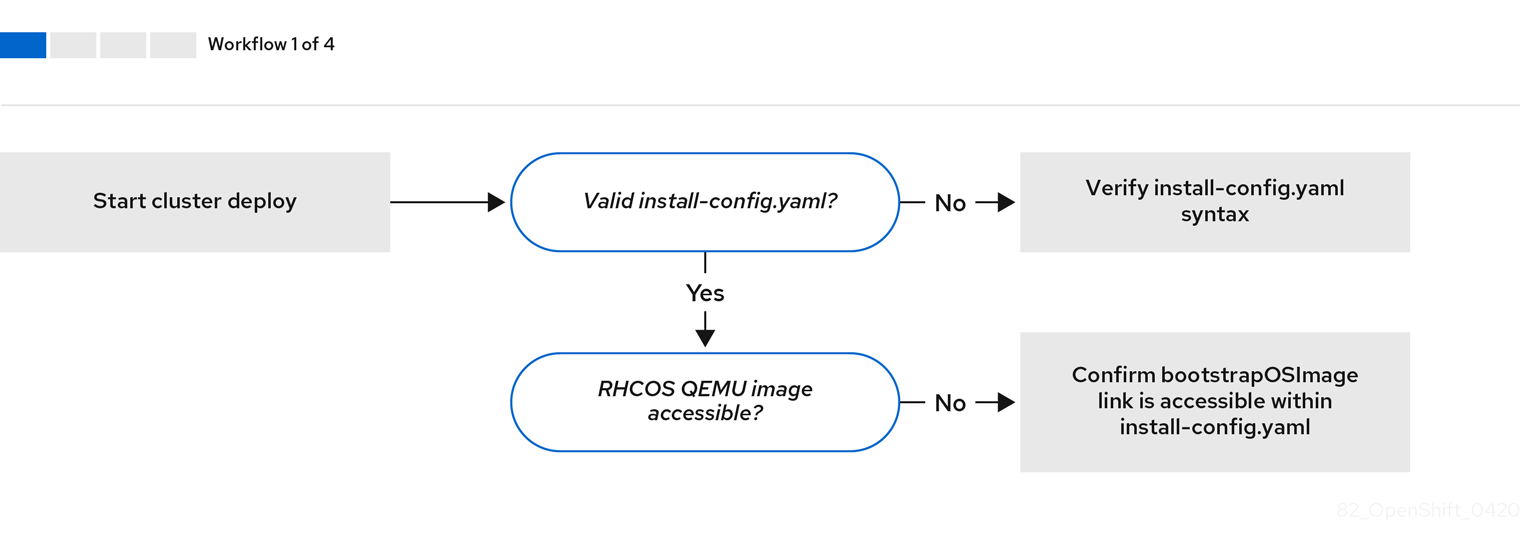
Workflow 1 of 4 illustrates a troubleshooting workflow when the install-config.yaml file has errors or the Red Hat Enterprise Linux CoreOS (RHCOS) images are inaccessible. See Troubleshooting install-config.yaml for troubleshooting suggestions.
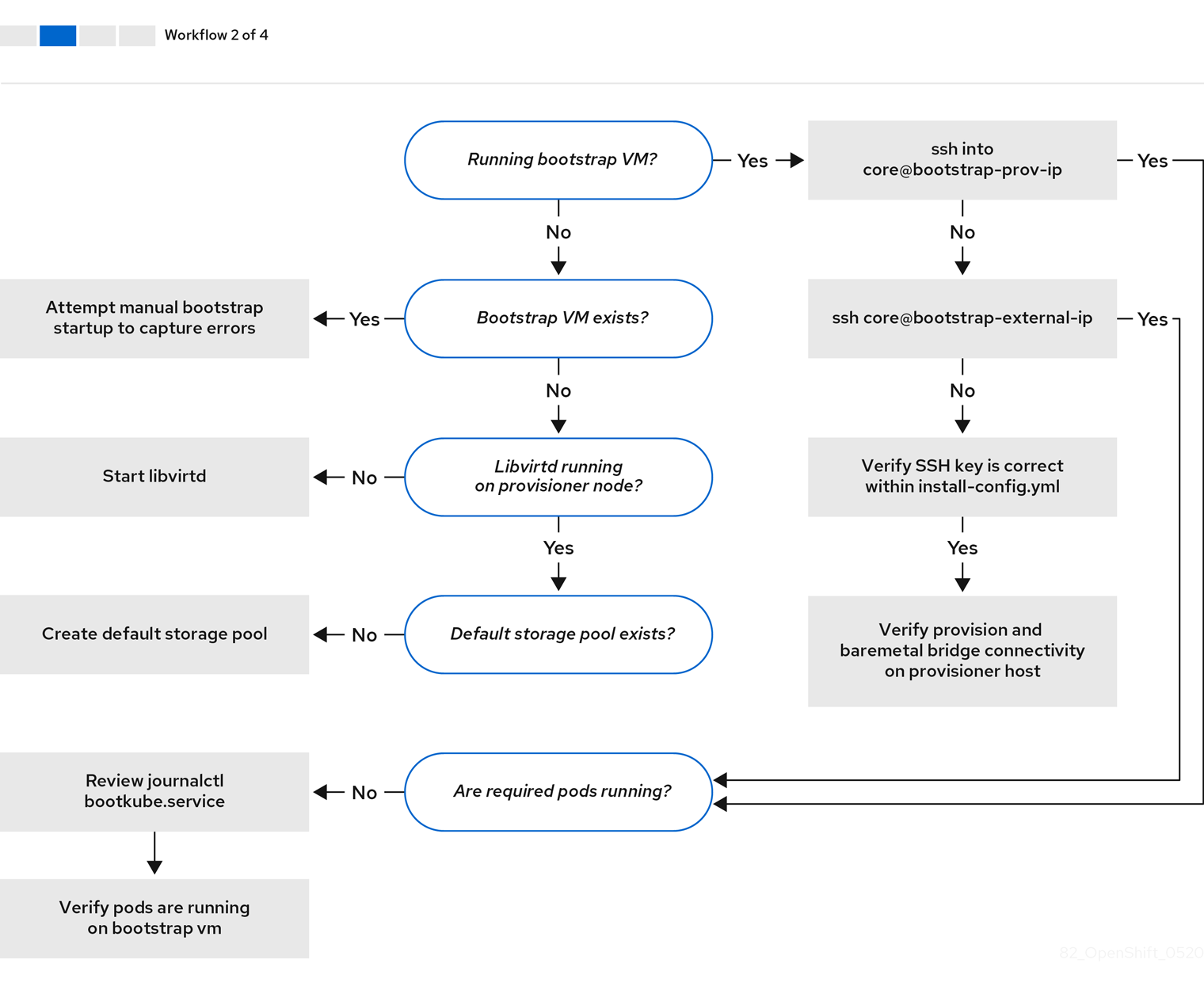
Workflow 2 of 4 illustrates a troubleshooting workflow for bootstrap VM issues, bootstrap VMs that cannot boot up the cluster nodes, and inspecting logs. When installing an OpenShift Container Platform cluster without the provisioning network, this workflow does not apply.
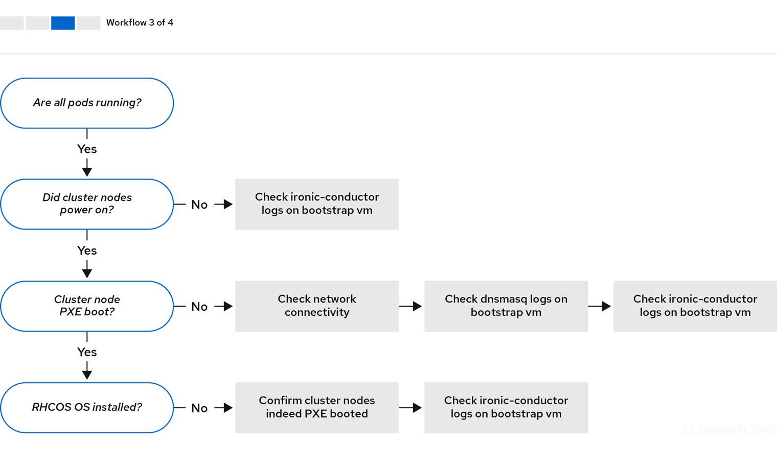
Workflow 3 of 4 illustrates a troubleshooting workflow for cluster nodes that will not PXE boot. If installing using Redfish virtual media, each node must meet minimum firmware requirements for the installation program to deploy the node. See Firmware requirements for installing with virtual media in the Prerequisites section for additional details.
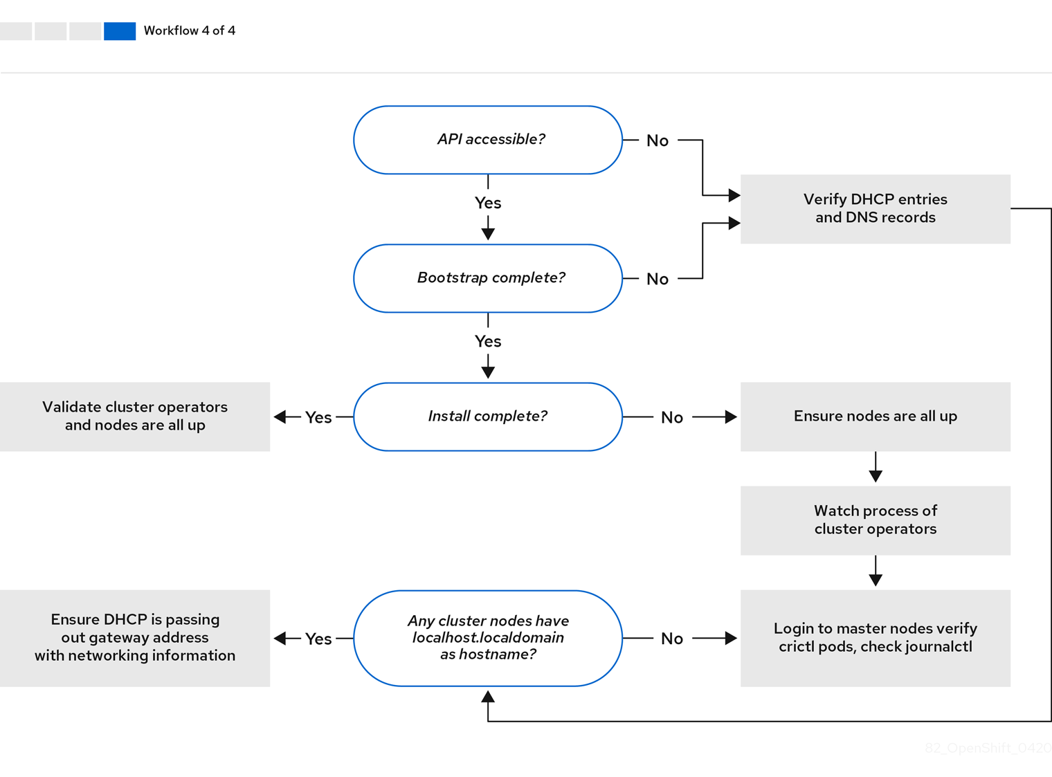
Workflow 4 of 4 illustrates a troubleshooting workflow from a non-accessible API to a validated installation.
3.5.2. Troubleshooting install-config.yaml
The install-config.yaml configuration file represents all of the nodes that are part of the OpenShift Container Platform cluster. The file contains the necessary options consisting of but not limited to apiVersion, baseDomain, imageContentSources and virtual IP addresses. If errors occur early in the deployment of the OpenShift Container Platform cluster, the errors are likely in the install-config.yaml configuration file.
Procedure
- Use the guidelines in YAML-tips.
- Verify the YAML syntax is correct using syntax-check.
Verify the Red Hat Enterprise Linux CoreOS (RHCOS) QEMU images are properly defined and accessible via the URL provided in the
install-config.yaml. For example:$ curl -s -o /dev/null -I -w "%{http_code}\n" http://webserver.example.com:8080/rhcos-44.81.202004250133-0-qemu.<architecture>.qcow2.gz?sha256=7d884b46ee54fe87bbc3893bf2aa99af3b2d31f2e19ab5529c60636fbd0f1ce7If the output is
200, there is a valid response from the webserver storing the bootstrap VM image.
3.5.3. Troubleshooting bootstrap VM issues
The OpenShift Container Platform installation program spawns a bootstrap node virtual machine, which handles provisioning the OpenShift Container Platform cluster nodes.
Procedure
About 10 to 15 minutes after triggering the installation program, check to ensure the bootstrap VM is operational using the
virshcommand:$ sudo virsh listId Name State -------------------------------------------- 12 openshift-xf6fq-bootstrap runningNoteThe name of the bootstrap VM is always the cluster name followed by a random set of characters and ending in the word "bootstrap."
If the bootstrap VM is not running after 10-15 minutes, verify
libvirtdis running on the system by executing the following command:$ systemctl status libvirtd● libvirtd.service - Virtualization daemon Loaded: loaded (/usr/lib/systemd/system/libvirtd.service; enabled; vendor preset: enabled) Active: active (running) since Tue 2020-03-03 21:21:07 UTC; 3 weeks 5 days ago Docs: man:libvirtd(8) https://libvirt.org Main PID: 9850 (libvirtd) Tasks: 20 (limit: 32768) Memory: 74.8M CGroup: /system.slice/libvirtd.service ├─ 9850 /usr/sbin/libvirtdIf the bootstrap VM is operational, log in to it.
Use the
virsh consolecommand to find the IP address of the bootstrap VM:$ sudo virsh console example.comConnected to domain example.com Escape character is ^] Red Hat Enterprise Linux CoreOS 43.81.202001142154.0 (Ootpa) 4.3 SSH host key: SHA256:BRWJktXZgQQRY5zjuAV0IKZ4WM7i4TiUyMVanqu9Pqg (ED25519) SSH host key: SHA256:7+iKGA7VtG5szmk2jB5gl/5EZ+SNcJ3a2g23o0lnIio (ECDSA) SSH host key: SHA256:DH5VWhvhvagOTaLsYiVNse9ca+ZSW/30OOMed8rIGOc (RSA) ens3: fd35:919d:4042:2:c7ed:9a9f:a9ec:7 ens4: 172.22.0.2 fe80::1d05:e52e:be5d:263f localhost login:ImportantWhen deploying an OpenShift Container Platform cluster without the
provisioningnetwork, you must use a public IP address and not a private IP address like172.22.0.2.After you obtain the IP address, log in to the bootstrap VM using the
sshcommand:NoteIn the console output of the previous step, you can use the IPv6 IP address provided by
ens3or the IPv4 IP provided byens4.$ ssh core@172.22.0.2
If you are not successful logging in to the bootstrap VM, you have likely encountered one of the following scenarios:
-
You cannot reach the
172.22.0.0/24network. Verify the network connectivity between the provisioner and theprovisioningnetwork bridge. This issue might occur if you are using aprovisioningnetwork. -
You cannot reach the bootstrap VM through the public network. When attempting to SSH via
baremetalnetwork, verify connectivity on theprovisionerhost specifically around thebaremetalnetwork bridge. -
You encountered
Permission denied (publickey,password,keyboard-interactive). When attempting to access the bootstrap VM, aPermission deniederror might occur. Verify that the SSH key for the user attempting to log in to the VM is set within theinstall-config.yamlfile.
3.5.3.1. Bootstrap VM cannot boot up the cluster nodes
During the deployment, it is possible for the bootstrap VM to fail to boot the cluster nodes, which prevents the VM from provisioning the nodes with the RHCOS image. This scenario can arise due to:
-
A problem with the
install-config.yamlfile. - Issues with out-of-band network access when using the baremetal network.
To verify the issue, there are three containers related to ironic:
-
ironic -
ironic-inspector
Procedure
Log in to the bootstrap VM:
$ ssh core@172.22.0.2To check the container logs, execute the following:
[core@localhost ~]$ sudo podman logs -f <container_name>Replace
<container_name>with one ofironicorironic-inspector. If you encounter an issue where the control plane nodes are not booting up from PXE, check theironicpod. Theironicpod contains information about the attempt to boot the cluster nodes, because it attempts to log in to the node over IPMI.
Potential reason
The cluster nodes might be in the ON state when deployment started.
Solution
Power off the OpenShift Container Platform cluster nodes before you begin the installation over IPMI:
$ ipmitool -I lanplus -U root -P <password> -H <out_of_band_ip> power off3.5.3.2. Inspecting logs
When experiencing issues downloading or accessing the RHCOS images, first verify that the URL is correct in the install-config.yaml configuration file.
Example of internal webserver hosting RHCOS images
bootstrapOSImage: http://<ip:port>/rhcos-43.81.202001142154.0-qemu.<architecture>.qcow2.gz?sha256=9d999f55ff1d44f7ed7c106508e5deecd04dc3c06095d34d36bf1cd127837e0c
clusterOSImage: http://<ip:port>/rhcos-43.81.202001142154.0-openstack.<architecture>.qcow2.gz?sha256=a1bda656fa0892f7b936fdc6b6a6086bddaed5dafacedcd7a1e811abb78fe3b0
The coreos-downloader container downloads resources from a webserver or from the external quay.io registry, whichever the install-config.yaml configuration file specifies. Verify that the coreos-downloader container is up and running and inspect its logs as needed.
Procedure
Log in to the bootstrap VM:
$ ssh core@172.22.0.2Check the status of the
coreos-downloadercontainer within the bootstrap VM by running the following command:[core@localhost ~]$ sudo podman logs -f coreos-downloaderIf the bootstrap VM cannot access the URL to the images, use the
curlcommand to verify that the VM can access the images.To inspect the
bootkubelogs that indicate if all the containers launched during the deployment phase, execute the following:[core@localhost ~]$ journalctl -xe[core@localhost ~]$ journalctl -b -f -u bootkube.serviceVerify all the pods, including
dnsmasq,mariadb,httpd, andironic, are running:[core@localhost ~]$ sudo podman psIf there are issues with the pods, check the logs of the containers with issues. To check the logs of the
ironicservice, run the following command:[core@localhost ~]$ sudo podman logs ironic
3.5.5. Troubleshooting a failure to initialize the cluster
The installation program uses the Cluster Version Operator to create all the components of an OpenShift Container Platform cluster. When the installation program fails to initialize the cluster, you can retrieve the most important information from the ClusterVersion and ClusterOperator objects.
Procedure
Inspect the
ClusterVersionobject by running the following command:$ oc --kubeconfig=${INSTALL_DIR}/auth/kubeconfig get clusterversion -o yamlExample output
apiVersion: config.openshift.io/v1 kind: ClusterVersion metadata: creationTimestamp: 2019-02-27T22:24:21Z generation: 1 name: version resourceVersion: "19927" selfLink: /apis/config.openshift.io/v1/clusterversions/version uid: 6e0f4cf8-3ade-11e9-9034-0a923b47ded4 spec: channel: stable-4.1 clusterID: 5ec312f9-f729-429d-a454-61d4906896ca status: availableUpdates: null conditions: - lastTransitionTime: 2019-02-27T22:50:30Z message: Done applying 4.1.1 status: "True" type: Available - lastTransitionTime: 2019-02-27T22:50:30Z status: "False" type: Failing - lastTransitionTime: 2019-02-27T22:50:30Z message: Cluster version is 4.1.1 status: "False" type: Progressing - lastTransitionTime: 2019-02-27T22:24:31Z message: 'Unable to retrieve available updates: unknown version 4.1.1 reason: RemoteFailed status: "False" type: RetrievedUpdates desired: image: registry.svc.ci.openshift.org/openshift/origin-release@sha256:91e6f754975963e7db1a9958075eb609ad226968623939d262d1cf45e9dbc39a version: 4.1.1 history: - completionTime: 2019-02-27T22:50:30Z image: registry.svc.ci.openshift.org/openshift/origin-release@sha256:91e6f754975963e7db1a9958075eb609ad226968623939d262d1cf45e9dbc39a startedTime: 2019-02-27T22:24:31Z state: Completed version: 4.1.1 observedGeneration: 1 versionHash: Wa7as_ik1qE=View the conditions by running the following command:
$ oc --kubeconfig=${INSTALL_DIR}/auth/kubeconfig get clusterversion version \ -o=jsonpath='{range .status.conditions[*]}{.type}{" "}{.status}{" "}{.message}{"\n"}{end}'Some of most important conditions include
Failing,AvailableandProgressing.Example output
Available True Done applying 4.1.1 Failing False Progressing False Cluster version is 4.0.0-0.alpha-2019-02-26-194020 RetrievedUpdates False Unable to retrieve available updates: unknown version 4.1.1Inspect the
ClusterOperatorobject by running the following command:$ oc --kubeconfig=${INSTALL_DIR}/auth/kubeconfig get clusteroperatorThe command returns the status of the cluster Operators.
Example output
NAME VERSION AVAILABLE PROGRESSING FAILING SINCE cluster-baremetal-operator True False False 17m cluster-autoscaler True False False 17m cluster-storage-operator True False False 10m console True False False 7m21s dns True False False 31m image-registry True False False 9m58s ingress True False False 10m kube-apiserver True False False 28m kube-controller-manager True False False 21m kube-scheduler True False False 25m machine-api True False False 17m machine-config True False False 17m marketplace-operator True False False 10m monitoring True False False 8m23s network True False False 13m node-tuning True False False 11m openshift-apiserver True False False 15m openshift-authentication True False False 20m openshift-cloud-credential-operator True False False 18m openshift-controller-manager True False False 10m openshift-samples True False False 8m42s operator-lifecycle-manager True False False 17m service-ca True False False 30mInspect individual cluster Operators by running the following command:
$ oc --kubeconfig=${INSTALL_DIR}/auth/kubeconfig get clusteroperator <operator> -oyaml1 - 1
- Replace
<operator>with the name of a cluster Operator. This command is useful for identifying why an cluster Operator has not achieved theAvailablestate or is in theFailedstate.
Example output
apiVersion: config.openshift.io/v1 kind: ClusterOperator metadata: creationTimestamp: 2019-02-27T22:47:04Z generation: 1 name: monitoring resourceVersion: "24677" selfLink: /apis/config.openshift.io/v1/clusteroperators/monitoring uid: 9a6a5ef9-3ae1-11e9-bad4-0a97b6ba9358 spec: {} status: conditions: - lastTransitionTime: 2019-02-27T22:49:10Z message: Successfully rolled out the stack. status: "True" type: Available - lastTransitionTime: 2019-02-27T22:49:10Z status: "False" type: Progressing - lastTransitionTime: 2019-02-27T22:49:10Z status: "False" type: Failing extension: null relatedObjects: null version: ""To get the cluster Operator’s status condition, run the following command:
$ oc --kubeconfig=${INSTALL_DIR}/auth/kubeconfig get clusteroperator <operator> \ -o=jsonpath='{range .status.conditions[*]}{.type}{" "}{.status}{" "}{.message}{"\n"}{end}'Replace
<operator>with the name of one of the operators above.Example output
Available True Successfully rolled out the stack Progressing False Failing FalseTo retrieve the list of objects owned by the cluster Operator, execute the following command:
oc --kubeconfig=${INSTALL_DIR}/auth/kubeconfig get clusteroperator kube-apiserver \ -o=jsonpath='{.status.relatedObjects}'Example output
[map[resource:kubeapiservers group:operator.openshift.io name:cluster] map[group: name:openshift-config resource:namespaces] map[group: name:openshift-config-managed resource:namespaces] map[group: name:openshift-kube-apiserver-operator resource:namespaces] map[group: name:openshift-kube-apiserver resource:namespaces]]
3.5.6. Troubleshooting a failure to fetch the console URL
The installation program retrieves the URL for the OpenShift Container Platform console by using [route][route-object] within the openshift-console namespace. If the installation program fails the retrieve the URL for the console, use the following procedure.
Procedure
Check if the console router is in the
AvailableorFailingstate by running the following command:$ oc --kubeconfig=${INSTALL_DIR}/auth/kubeconfig get clusteroperator console -oyamlapiVersion: config.openshift.io/v1 kind: ClusterOperator metadata: creationTimestamp: 2019-02-27T22:46:57Z generation: 1 name: console resourceVersion: "19682" selfLink: /apis/config.openshift.io/v1/clusteroperators/console uid: 960364aa-3ae1-11e9-bad4-0a97b6ba9358 spec: {} status: conditions: - lastTransitionTime: 2019-02-27T22:46:58Z status: "False" type: Failing - lastTransitionTime: 2019-02-27T22:50:12Z status: "False" type: Progressing - lastTransitionTime: 2019-02-27T22:50:12Z status: "True" type: Available - lastTransitionTime: 2019-02-27T22:46:57Z status: "True" type: Upgradeable extension: null relatedObjects: - group: operator.openshift.io name: cluster resource: consoles - group: config.openshift.io name: cluster resource: consoles - group: oauth.openshift.io name: console resource: oauthclients - group: "" name: openshift-console-operator resource: namespaces - group: "" name: openshift-console resource: namespaces versions: nullManually retrieve the console URL by executing the following command:
$ oc --kubeconfig=${INSTALL_DIR}/auth/kubeconfig get route console -n openshift-console \ -o=jsonpath='{.spec.host}' console-openshift-console.apps.adahiya-1.devcluster.openshift.com
3.5.7. Troubleshooting a failure to add the ingress certificate to kubeconfig
The installation program adds the default ingress certificate to the list of trusted client certificate authorities in ${INSTALL_DIR}/auth/kubeconfig. If the installation program fails to add the ingress certificate to the kubeconfig file, you can retrieve the certificate from the cluster and add it.
Procedure
Retrieve the certificate from the cluster using the following command:
$ oc --kubeconfig=${INSTALL_DIR}/auth/kubeconfig get configmaps default-ingress-cert \ -n openshift-config-managed -o=jsonpath='{.data.ca-bundle\.crt}'-----BEGIN CERTIFICATE----- MIIC/TCCAeWgAwIBAgIBATANBgkqhkiG9w0BAQsFADAuMSwwKgYDVQQDDCNjbHVz dGVyLWluZ3Jlc3Mtb3BlcmF0b3JAMTU1MTMwNzU4OTAeFw0xOTAyMjcyMjQ2Mjha Fw0yMTAyMjYyMjQ2MjlaMC4xLDAqBgNVBAMMI2NsdXN0ZXItaW5ncmVzcy1vcGVy YXRvckAxNTUxMzA3NTg5MIIBIjANBgkqhkiG9w0BAQEFAAOCAQ8AMIIBCgKCAQEA uCA4fQ+2YXoXSUL4h/mcvJfrgpBfKBW5hfB8NcgXeCYiQPnCKblH1sEQnI3VC5Pk 2OfNCF3PUlfm4i8CHC95a7nCkRjmJNg1gVrWCvS/ohLgnO0BvszSiRLxIpuo3C4S EVqqvxValHcbdAXWgZLQoYZXV7RMz8yZjl5CfhDaaItyBFj3GtIJkXgUwp/5sUfI LDXW8MM6AXfuG+kweLdLCMm3g8WLLfLBLvVBKB+4IhIH7ll0buOz04RKhnYN+Ebw tcvFi55vwuUCWMnGhWHGEQ8sWm/wLnNlOwsUz7S1/sW8nj87GFHzgkaVM9EOnoNI gKhMBK9ItNzjrP6dgiKBCQIDAQABoyYwJDAOBgNVHQ8BAf8EBAMCAqQwEgYDVR0T AQH/BAgwBgEB/wIBADANBgkqhkiG9w0BAQsFAAOCAQEAq+vi0sFKudaZ9aUQMMha CeWx9CZvZBblnAWT/61UdpZKpFi4eJ2d33lGcfKwHOi2NP/iSKQBebfG0iNLVVPz vwLbSG1i9R9GLdAbnHpPT9UG6fLaDIoKpnKiBfGENfxeiq5vTln2bAgivxrVlyiq +MdDXFAWb6V4u2xh6RChI7akNsS3oU9PZ9YOs5e8vJp2YAEphht05X0swA+X8V8T C278FFifpo0h3Q0Dbv8Rfn4UpBEtN4KkLeS+JeT+0o2XOsFZp7Uhr9yFIodRsnNo H/Uwmab28ocNrGNiEVaVH6eTTQeeZuOdoQzUbClElpVmkrNGY0M42K0PvOQ/e7+y AQ== -----END CERTIFICATE------
Add the certificate to the
client-certificate-authority-datafield in the${INSTALL_DIR}/auth/kubeconfigfile.
3.5.8. Troubleshooting SSH access to cluster nodes
For added security, you cannot SSH into the cluster from outside the cluster by default. However, you can access control plane and worker nodes from the provisioner node. If you cannot SSH into the cluster nodes from the provisioner node, the nodes might be waiting on the bootstrap VM. The control plane nodes retrieve their boot configuration from the bootstrap VM, and they cannot boot successfully if they do not retrieve the boot configuration.
Procedure
- If you have physical access to the nodes, check their console output to determine if they have successfully booted. If the nodes are still retrieving their boot configuration, there might be problems with the bootstrap VM .
-
Ensure you have configured the
sshKey: '<ssh_pub_key>'setting in theinstall-config.yamlfile, where<ssh_pub_key>is the public key of thekniuser on the provisioner node.
3.5.9. Cluster nodes will not PXE boot
When OpenShift Container Platform cluster nodes will not PXE boot, execute the following checks on the cluster nodes that will not PXE boot. This procedure does not apply when installing an OpenShift Container Platform cluster without the provisioning network.
Procedure
-
Check the network connectivity to the
provisioningnetwork. -
Ensure PXE is enabled on the NIC for the
provisioningnetwork and PXE is disabled for all other NICs. Verify that the
install-config.yamlconfiguration file includes therootDeviceHintsparameter and boot MAC address for the NIC connected to theprovisioningnetwork. For example:control plane node settings
bootMACAddress: 24:6E:96:1B:96:90 # MAC of bootable provisioning NICWorker node settings
bootMACAddress: 24:6E:96:1B:96:90 # MAC of bootable provisioning NIC
3.5.10. Installing creates no worker nodes
The installation program does not provision worker nodes directly. Instead, the Machine API Operator scales nodes up and down on supported platforms. If worker nodes are not created after 15 to 20 minutes, depending on the speed of the cluster’s internet connection, investigate the Machine API Operator.
Procedure
Check the Machine API Operator by running the following command:
$ oc --kubeconfig=${INSTALL_DIR}/auth/kubeconfig \ --namespace=openshift-machine-api get deploymentsIf
${INSTALL_DIR}is not set in your environment, replace the value with the name of the installation directory.Example output
NAME READY UP-TO-DATE AVAILABLE AGE cluster-autoscaler-operator 1/1 1 1 86m cluster-baremetal-operator 1/1 1 1 86m machine-api-controllers 1/1 1 1 85m machine-api-operator 1/1 1 1 86mCheck the machine controller logs by running the following command:
$ oc --kubeconfig=${INSTALL_DIR}/auth/kubeconfig \ --namespace=openshift-machine-api logs deployments/machine-api-controllers \ --container=machine-controller
3.5.11. Troubleshooting the Cluster Network Operator
The Cluster Network Operator is responsible for deploying the networking components. It runs early in the installation process, after the control plane nodes have come up but before the installation program removes the bootstrap control plane. Issues with this Operator might indicate installation program issues.
Procedure
Ensure the network configuration exists by running the following command:
$ oc get network -o yaml clusterIf it does not exist, the installation program did not create it. To find out why, run the following command:
$ openshift-install create manifestsReview the manifests to determine why the installation program did not create the network configuration.
Ensure the network is running by entering the following command:
$ oc get po -n openshift-network-operator
3.5.12. Unable to discover new bare metal hosts using the BMC
In some cases, the installation program will not be able to discover the new bare metal hosts and issue an error, because it cannot mount the remote virtual media share.
For example:
ProvisioningError 51s metal3-baremetal-controller Image provisioning failed: Deploy step deploy.deploy failed with BadRequestError: HTTP POST
https://<bmc_address>/redfish/v1/Managers/iDRAC.Embedded.1/VirtualMedia/CD/Actions/VirtualMedia.InsertMedia
returned code 400.
Base.1.8.GeneralError: A general error has occurred. See ExtendedInfo for more information
Extended information: [
{
"Message": "Unable to mount remote share https://<ironic_address>/redfish/boot-<uuid>.iso.",
"MessageArgs": [
"https://<ironic_address>/redfish/boot-<uuid>.iso"
],
"MessageArgs@odata.count": 1,
"MessageId": "IDRAC.2.5.RAC0720",
"RelatedProperties": [
"#/Image"
],
"RelatedProperties@odata.count": 1,
"Resolution": "Retry the operation.",
"Severity": "Informational"
}
].In this situation, if you are using virtual media with an unknown certificate authority, you can configure your baseboard management controller (BMC) remote file share settings to trust an unknown certificate authority to avoid this error.
This resolution was tested on OpenShift Container Platform 4.11 with Dell iDRAC 9 and firmware version 5.10.50.
3.5.13. Troubleshooting worker nodes that cannot join the cluster
Installer-provisioned clusters deploy with a DNS server that includes a DNS entry for the api-int.<cluster_name>.<base_domain> URL. If the nodes within the cluster use an external or upstream DNS server to resolve the api-int.<cluster_name>.<base_domain> URL and there is no such entry, worker nodes might fail to join the cluster. Ensure that all nodes in the cluster can resolve the domain name.
Procedure
Add a DNS A/AAAA or CNAME record to internally identify the API load balancer. For example, when using dnsmasq, modify the
dnsmasq.confconfiguration file:$ sudo nano /etc/dnsmasq.confaddress=/api-int.<cluster_name>.<base_domain>/<IP_address> address=/api-int.mycluster.example.com/192.168.1.10 address=/api-int.mycluster.example.com/2001:0db8:85a3:0000:0000:8a2e:0370:7334Add a DNS PTR record to internally identify the API load balancer. For example, when using dnsmasq, modify the
dnsmasq.confconfiguration file:$ sudo nano /etc/dnsmasq.confptr-record=<IP_address>.in-addr.arpa,api-int.<cluster_name>.<base_domain> ptr-record=10.1.168.192.in-addr.arpa,api-int.mycluster.example.comRestart the DNS server. For example, when using dnsmasq, execute the following command:
$ sudo systemctl restart dnsmasq
These records must be resolvable from all the nodes within the cluster.
3.5.14. Cleaning up previous installations
In case of an earlier failed deployment, remove the artifacts from the failed attempt before trying to deploy OpenShift Container Platform again.
Procedure
Power off all bare-metal nodes before installing the OpenShift Container Platform cluster by using the following command:
$ ipmitool -I lanplus -U <user> -P <password> -H <management_server_ip> power offRemove all old bootstrap resources if any remain from an earlier deployment attempt by using the following script:
for i in $(sudo virsh list | tail -n +3 | grep bootstrap | awk {'print $2'}); do sudo virsh destroy $i; sudo virsh undefine $i; sudo virsh vol-delete $i --pool $i; sudo virsh vol-delete $i.ign --pool $i; sudo virsh pool-destroy $i; sudo virsh pool-undefine $i; doneDelete the artifacts that the earlier installation generated by using the following command:
$ cd ; /bin/rm -rf auth/ bootstrap.ign master.ign worker.ign metadata.json \ .openshift_install.log .openshift_install_state.jsonRe-create the OpenShift Container Platform manifests by using the following command:
$ ./openshift-baremetal-install --dir ~/clusterconfigs create manifests
3.5.15. Issues with creating the registry
When creating a disconnected registry, you might encounter a "User Not Authorized" error when attempting to mirror the registry. This error might occur if you fail to append the new authentication to the existing pull-secret.txt file.
Procedure
Check to ensure authentication is successful:
$ /usr/local/bin/oc adm release mirror \ -a pull-secret-update.json --from=$UPSTREAM_REPO \ --to-release-image=$LOCAL_REG/$LOCAL_REPO:${VERSION} \ --to=$LOCAL_REG/$LOCAL_REPONoteExample output of the variables used to mirror the install images:
UPSTREAM_REPO=${RELEASE_IMAGE} LOCAL_REG=<registry_FQDN>:<registry_port> LOCAL_REPO='ocp4/openshift4'The values of
RELEASE_IMAGEandVERSIONwere set during the Retrieving OpenShift Installer step of the Setting up the environment for an OpenShift installation section.After mirroring the registry, confirm that you can access it in your disconnected environment:
$ curl -k -u <user>:<password> https://registry.example.com:<registry_port>/v2/_catalog {"repositories":["<Repo_Name>"]}
3.5.16. Miscellaneous issues
3.5.16.1. Addressing the runtime network not ready error
After the deployment of a cluster you might receive the following error:
`runtime network not ready: NetworkReady=false reason:NetworkPluginNotReady message:Network plugin returns error: Missing CNI default network`
The Cluster Network Operator is responsible for deploying the networking components in response to a special object created by the installation program. It runs very early in the installation process, after the control plane (master) nodes have come up, but before the bootstrap control plane has been torn down. It can be indicative of more subtle installation program issues, such as long delays in bringing up control plane (master) nodes or issues with apiserver communication.
Procedure
Inspect the pods in the
openshift-network-operatornamespace:$ oc get all -n openshift-network-operatorNAME READY STATUS RESTARTS AGE pod/network-operator-69dfd7b577-bg89v 0/1 ContainerCreating 0 149mOn the
provisionernode, determine that the network configuration exists:$ kubectl get network.config.openshift.io cluster -oyamlapiVersion: config.openshift.io/v1 kind: Network metadata: name: cluster spec: serviceNetwork: - 172.30.0.0/16 clusterNetwork: - cidr: 10.128.0.0/14 hostPrefix: 23 networkType: OVNKubernetesIf it does not exist, the installation program did not create it. To determine why the installation program did not create it, execute the following:
$ openshift-install create manifestsCheck that the
network-operatoris running:$ kubectl -n openshift-network-operator get podsRetrieve the logs:
$ kubectl -n openshift-network-operator logs -l "name=network-operator"On high availability clusters with three or more control plane nodes, the Operator will perform leader election and all other Operators will sleep. For additional details, see Troubleshooting.
3.5.16.2. Addressing the "No disk found with matching rootDeviceHints" error message
After you deploy a cluster, you might receive the following error message:
No disk found with matching rootDeviceHints
To address the No disk found with matching rootDeviceHints error message, a temporary workaround is to change the rootDeviceHints to minSizeGigabytes: 300.
After you change the rootDeviceHints settings, boot the CoreOS and then verify the disk information by using the following command:
$ udevadm info /dev/sda
If you are using DL360 Gen 10 servers, be aware that they have an SD-card slot that might be assigned the /dev/sda device name. If no SD card is present in the server, it can cause conflicts. Ensure that the SD card slot is disabled in the server’s BIOS settings.
If the minSizeGigabytes workaround is not fulfilling the requirements, you might need to revert rootDeviceHints back to /dev/sda. This change allows ironic images to boot successfully.
An alternative approach to fixing this problem is by using the serial ID of the disk. However, be aware that finding the serial ID can be challenging and might make the configuration file less readable. If you choose this path, ensure that you gather the serial ID using the previously documented command and incorporate it into your configuration.
3.5.16.3. Cluster nodes not getting the correct IPv6 address over DHCP
If the cluster nodes are not getting the correct IPv6 address over DHCP, check the following:
- Ensure the reserved IPv6 addresses reside outside the DHCP range.
In the IP address reservation on the DHCP server, ensure the reservation specifies the correct DHCP Unique Identifier (DUID). For example:
# This is a dnsmasq dhcp reservation, 'id:00:03:00:01' is the client id and '18:db:f2:8c:d5:9f' is the MAC Address for the NIC id:00:03:00:01:18:db:f2:8c:d5:9f,openshift-master-1,[2620:52:0:1302::6]- Ensure that route announcements are working.
- Ensure that the DHCP server is listening on the required interfaces serving the IP address ranges.
3.5.16.4. Cluster nodes not getting the correct hostname over DHCP
During IPv6 deployment, cluster nodes must get their hostname over DHCP. Sometimes the NetworkManager does not assign the hostname immediately. A control plane (master) node might report an error such as:
Failed Units: 2
NetworkManager-wait-online.service
nodeip-configuration.service
This error indicates that the cluster node likely booted without first receiving a hostname from the DHCP server, which causes kubelet to boot with a localhost.localdomain hostname. To address the error, force the node to renew the hostname.
Procedure
Retrieve the
hostname:[core@master-X ~]$ hostnameIf the hostname is
localhost, proceed with the following steps.NoteWhere
Xis the control plane node number.Force the cluster node to renew the DHCP lease:
[core@master-X ~]$ sudo nmcli con up "<bare_metal_nic>"Replace
<bare_metal_nic>with the wired connection corresponding to thebaremetalnetwork.Check
hostnameagain:[core@master-X ~]$ hostnameIf the hostname is still
localhost.localdomain, restartNetworkManager:[core@master-X ~]$ sudo systemctl restart NetworkManager-
If the hostname is still
localhost.localdomain, wait a few minutes and check again. If the hostname remainslocalhost.localdomain, repeat the previous steps. Restart the
nodeip-configurationservice:[core@master-X ~]$ sudo systemctl restart nodeip-configuration.serviceThis service will reconfigure the
kubeletservice with the correct hostname references.Reload the unit files definition since the kubelet changed in the previous step:
[core@master-X ~]$ sudo systemctl daemon-reloadRestart the
kubeletservice:[core@master-X ~]$ sudo systemctl restart kubelet.serviceEnsure
kubeletbooted with the correct hostname:[core@master-X ~]$ sudo journalctl -fu kubelet.service
If the cluster node is not getting the correct hostname over DHCP after the cluster is up and running, such as during a reboot, the cluster will have a pending csr. Do not approve a csr, or other issues might arise.
Addressing a csr
Get CSRs on the cluster:
$ oc get csrVerify if a pending
csrcontainsSubject Name: localhost.localdomain:$ oc get csr <pending_csr> -o jsonpath='{.spec.request}' | base64 --decode | openssl req -noout -textRemove any
csrthat containsSubject Name: localhost.localdomain:$ oc delete csr <wrong_csr>
3.5.16.5. Routes do not reach endpoints
During the installation process, it is possible to encounter a Virtual Router Redundancy Protocol (VRRP) conflict. This conflict might occur if a previously used OpenShift Container Platform node that was once part of a cluster deployment using a specific cluster name is still running but not part of the current OpenShift Container Platform cluster deployment using that same cluster name. For example, a cluster was deployed using the cluster name openshift, deploying three control plane (master) nodes and three worker nodes. Later, a separate install uses the same cluster name openshift, but this redeployment only installed three control plane (master) nodes, leaving the three worker nodes from a previous deployment in an ON state. This might cause a Virtual Router Identifier (VRID) conflict and a VRRP conflict.
Get the route:
$ oc get route oauth-openshiftCheck the service endpoint:
$ oc get svc oauth-openshiftNAME TYPE CLUSTER-IP EXTERNAL-IP PORT(S) AGE oauth-openshift ClusterIP 172.30.19.162 <none> 443/TCP 59mAttempt to reach the service from a control plane (master) node:
[core@master0 ~]$ curl -k https://172.30.19.162{ "kind": "Status", "apiVersion": "v1", "metadata": { }, "status": "Failure", "message": "forbidden: User \"system:anonymous\" cannot get path \"/\"", "reason": "Forbidden", "details": { }, "code": 403Identify the
authentication-operatorerrors from theprovisionernode:$ oc logs deployment/authentication-operator -n openshift-authentication-operatorEvent(v1.ObjectReference{Kind:"Deployment", Namespace:"openshift-authentication-operator", Name:"authentication-operator", UID:"225c5bd5-b368-439b-9155-5fd3c0459d98", APIVersion:"apps/v1", ResourceVersion:"", FieldPath:""}): type: 'Normal' reason: 'OperatorStatusChanged' Status for clusteroperator/authentication changed: Degraded message changed from "IngressStateEndpointsDegraded: All 2 endpoints for oauth-server are reporting"
Solution
- Ensure that the cluster name for every deployment is unique, ensuring no conflict.
- Turn off all the rogue nodes which are not part of the cluster deployment that are using the same cluster name. Otherwise, the authentication pod of the OpenShift Container Platform cluster might never start successfully.
3.5.16.6. Failed Ignition during Firstboot
During the Firstboot, the Ignition configuration may fail.
Procedure
Connect to the node where the Ignition configuration failed:
Failed Units: 1 machine-config-daemon-firstboot.serviceRestart the
machine-config-daemon-firstbootservice:[core@worker-X ~]$ sudo systemctl restart machine-config-daemon-firstboot.service
3.5.16.7. NTP out of sync
The deployment of OpenShift Container Platform clusters depends on NTP synchronized clocks among the cluster nodes. Without synchronized clocks, the deployment may fail due to clock drift if the time difference is greater than two seconds.
Procedure
Check for differences in the
AGEof the cluster nodes. For example:$ oc get nodesNAME STATUS ROLES AGE VERSION master-0.cloud.example.com Ready master 145m v1.31.3 master-1.cloud.example.com Ready master 135m v1.31.3 master-2.cloud.example.com Ready master 145m v1.31.3 worker-2.cloud.example.com Ready worker 100m v1.31.3Check for inconsistent timing delays due to clock drift. For example:
$ oc get bmh -n openshift-machine-apimaster-1 error registering master-1 ipmi://<out_of_band_ip>$ sudo timedatectlLocal time: Tue 2020-03-10 18:20:02 UTC Universal time: Tue 2020-03-10 18:20:02 UTC RTC time: Tue 2020-03-10 18:36:53 Time zone: UTC (UTC, +0000) System clock synchronized: no NTP service: active RTC in local TZ: no
Addressing clock drift in existing clusters
Create a Butane config file including the contents of the
chrony.conffile to be delivered to the nodes. In the following example, create99-master-chrony.buto add the file to the control plane nodes. You can modify the file for worker nodes or repeat this procedure for the worker role.NoteSee "Creating machine configs with Butane" for information about Butane.
variant: openshift version: 4.18.0 metadata: name: 99-master-chrony labels: machineconfiguration.openshift.io/role: master storage: files: - path: /etc/chrony.conf mode: 0644 overwrite: true contents: inline: | server <NTP_server> iburst1 stratumweight 0 driftfile /var/lib/chrony/drift rtcsync makestep 10 3 bindcmdaddress 127.0.0.1 bindcmdaddress ::1 keyfile /etc/chrony.keys commandkey 1 generatecommandkey noclientlog logchange 0.5 logdir /var/log/chrony- 1
- Replace
<NTP_server>with the IP address of the NTP server.
Use Butane to generate a
MachineConfigobject file,99-master-chrony.yaml, containing the configuration to be delivered to the nodes:$ butane 99-master-chrony.bu -o 99-master-chrony.yamlApply the
MachineConfigobject file:$ oc apply -f 99-master-chrony.yamlEnsure the
System clock synchronizedvalue is yes:$ sudo timedatectlLocal time: Tue 2020-03-10 19:10:02 UTC Universal time: Tue 2020-03-10 19:10:02 UTC RTC time: Tue 2020-03-10 19:36:53 Time zone: UTC (UTC, +0000) System clock synchronized: yes NTP service: active RTC in local TZ: noTo setup clock synchronization prior to deployment, generate the manifest files and add this file to the
openshiftdirectory. For example:$ cp chrony-masters.yaml ~/clusterconfigs/openshift/99_masters-chrony-configuration.yamlThen, continue to create the cluster.
3.5.17. Reviewing the installation
After installation, ensure the installation program deployed the nodes and pods successfully.
Procedure
When the OpenShift Container Platform cluster nodes are installed appropriately, the following
Readystate is seen within theSTATUScolumn:$ oc get nodesNAME STATUS ROLES AGE VERSION master-0.example.com Ready master,worker 4h v1.31.3 master-1.example.com Ready master,worker 4h v1.31.3 master-2.example.com Ready master,worker 4h v1.31.3Confirm the installation program deployed all pods successfully. The following command removes any pods that are still running or have completed as part of the output.
$ oc get pods --all-namespaces | grep -iv running | grep -iv complete
Chapter 4. Installer-provisioned postinstallation configuration
After successfully deploying an installer-provisioned cluster, consider the following postinstallation procedures.
4.1. Configuring NTP for disconnected clusters
OpenShift Container Platform installs the chrony Network Time Protocol (NTP) service on the cluster nodes.
OpenShift Container Platform nodes must agree on a date and time to run properly. When compute nodes retrieve the date and time from the NTP servers on the control plane nodes, it enables the installation and operation of clusters that are not connected to a routable network and thereby do not have access to a higher stratum NTP server.
Procedure
Install Butane on your installation host by using the following command:
$ sudo dnf -y install butaneCreate a Butane config,
99-master-chrony-conf-override.bu, including the contents of thechrony.conffile for the control plane nodes.NoteSee "Creating machine configs with Butane" for information about Butane.
Butane config example
variant: openshift version: 4.18.0 metadata: name: 99-master-chrony-conf-override labels: machineconfiguration.openshift.io/role: master storage: files: - path: /etc/chrony.conf mode: 0644 overwrite: true contents: inline: | # Use public servers from the pool.ntp.org project. # Please consider joining the pool (https://www.pool.ntp.org/join.html). # The Machine Config Operator manages this file server openshift-master-0.<cluster-name>.<domain> iburst1 server openshift-master-1.<cluster-name>.<domain> iburst server openshift-master-2.<cluster-name>.<domain> iburst stratumweight 0 driftfile /var/lib/chrony/drift rtcsync makestep 10 3 bindcmdaddress 127.0.0.1 bindcmdaddress ::1 keyfile /etc/chrony.keys commandkey 1 generatecommandkey noclientlog logchange 0.5 logdir /var/log/chrony # Configure the control plane nodes to serve as local NTP servers # for all compute nodes, even if they are not in sync with an # upstream NTP server. # Allow NTP client access from the local network. allow all # Serve time even if not synchronized to a time source. local stratum 3 orphan- 1
- You must replace
<cluster-name>with the name of the cluster and replace<domain>with the fully qualified domain name.
Use Butane to generate a
MachineConfigobject file,99-master-chrony-conf-override.yaml, containing the configuration to be delivered to the control plane nodes:$ butane 99-master-chrony-conf-override.bu -o 99-master-chrony-conf-override.yamlCreate a Butane config,
99-worker-chrony-conf-override.bu, including the contents of thechrony.conffile for the compute nodes that references the NTP servers on the control plane nodes.Butane config example
variant: openshift version: 4.18.0 metadata: name: 99-worker-chrony-conf-override labels: machineconfiguration.openshift.io/role: worker storage: files: - path: /etc/chrony.conf mode: 0644 overwrite: true contents: inline: | # The Machine Config Operator manages this file. server openshift-master-0.<cluster-name>.<domain> iburst1 server openshift-master-1.<cluster-name>.<domain> iburst server openshift-master-2.<cluster-name>.<domain> iburst stratumweight 0 driftfile /var/lib/chrony/drift rtcsync makestep 10 3 bindcmdaddress 127.0.0.1 bindcmdaddress ::1 keyfile /etc/chrony.keys commandkey 1 generatecommandkey noclientlog logchange 0.5 logdir /var/log/chrony- 1
- You must replace
<cluster-name>with the name of the cluster and replace<domain>with the fully qualified domain name.
Use Butane to generate a
MachineConfigobject file,99-worker-chrony-conf-override.yaml, containing the configuration to be delivered to the worker nodes:$ butane 99-worker-chrony-conf-override.bu -o 99-worker-chrony-conf-override.yaml
4.2. Enabling a provisioning network after installation
The assisted installer and installer-provisioned installation for bare metal clusters provide the ability to deploy a cluster without a provisioning network. This capability is for scenarios such as proof-of-concept clusters or deploying exclusively with Redfish virtual media when each node’s baseboard management controller is routable via the baremetal network.
You can enable a provisioning network after installation using the Cluster Baremetal Operator (CBO).
Prerequisites
- A dedicated physical network must exist, connected to all worker and control plane nodes.
- You must isolate the native, untagged physical network.
-
The network cannot have a DHCP server when the
provisioningNetworkconfiguration setting is set toManaged. -
You can omit the
provisioningInterfacesetting in OpenShift Container Platform 4.10 to use thebootMACAddressconfiguration setting.
Procedure
-
When setting the
provisioningInterfacesetting, first identify the provisioning interface name for the cluster nodes. For example,eth0oreno1. -
Enable the Preboot eXecution Environment (PXE) on the
provisioningnetwork interface of the cluster nodes. Retrieve the current state of the
provisioningnetwork and save it to a provisioning custom resource (CR) file:$ oc get provisioning -o yaml > enable-provisioning-nw.yamlModify the provisioning CR file:
$ vim ~/enable-provisioning-nw.yamlScroll down to the
provisioningNetworkconfiguration setting and change it fromDisabledtoManaged. Then, add theprovisioningIP,provisioningNetworkCIDR,provisioningDHCPRange,provisioningInterface, andwatchAllNameSpacesconfiguration settings after theprovisioningNetworksetting. Provide appropriate values for each setting.apiVersion: v1 items: - apiVersion: metal3.io/v1alpha1 kind: Provisioning metadata: name: provisioning-configuration spec: provisioningNetwork:1 provisioningIP:2 provisioningNetworkCIDR:3 provisioningDHCPRange:4 provisioningInterface:5 watchAllNameSpaces:6 - 1
- The
provisioningNetworkis one ofManaged,Unmanaged, orDisabled. When set toManaged, Metal3 manages the provisioning network and the CBO deploys the Metal3 pod with a configured DHCP server. When set toUnmanaged, the system administrator configures the DHCP server manually. - 2
- The
provisioningIPis the static IP address that the DHCP server and ironic use to provision the network. This static IP address must be within theprovisioningsubnet, and outside of the DHCP range. If you configure this setting, it must have a valid IP address even if theprovisioningnetwork isDisabled. The static IP address is bound to the metal3 pod. If the metal3 pod fails and moves to another server, the static IP address also moves to the new server. - 3
- The Classless Inter-Domain Routing (CIDR) address. If you configure this setting, it must have a valid CIDR address even if the
provisioningnetwork isDisabled. For example:192.168.0.1/24. - 4
- The DHCP range. This setting is only applicable to a
Managedprovisioning network. Omit this configuration setting if theprovisioningnetwork isDisabled. For example:192.168.0.64, 192.168.0.253. - 5
- The NIC name for the
provisioninginterface on cluster nodes. TheprovisioningInterfacesetting is only applicable toManagedandUnmanagedprovisioning networks. Omit theprovisioningInterfaceconfiguration setting if theprovisioningnetwork isDisabled. Omit theprovisioningInterfaceconfiguration setting to use thebootMACAddressconfiguration setting instead. - 6
- Set this setting to
trueif you want metal3 to watch namespaces other than the defaultopenshift-machine-apinamespace. The default value isfalse.
- Save the changes to the provisioning CR file.
Apply the provisioning CR file to the cluster:
$ oc apply -f enable-provisioning-nw.yaml
4.3. Creating a manifest object that includes a customized br-ex bridge
Consider using the default OVS br-ex bridge configuration if you require a standard environment with a single network interface controller (NIC) and standard OVS settings.
By default, OpenShift Container Platform automatically configures the Open vSwitch (OVS) br-ex bridge on bare-metal nodes. For advanced networking requirements, you can override the default behavior by creating a NodeNetworkConfigurationPolicy (NNCP) custom resource (CR) that includes an NMState configuration file.
The Kubernetes NMState Operator uses the NMState configuration file to create a customized br-ex bridge network configuration on each node in your cluster.
After creating the NodeNetworkConfigurationPolicy CR, copy content from the NMState configuration file that was created during cluster installation into the NNCP CR. An incomplete NNCP CR can result in loss of network connectivity, because the NNCP overrides all existing policies.
Consider using the customized br-ex bridge configuration for any of the following tasks:
-
You want to make postinstallation changes to the bridge, such as changing the Open vSwitch (OVS) or OVN-Kubernetes
br-exbridge network. The default OVSbr-exbridge mechanism does not support making postinstallation changes to the bridge. - You want to deploy the bridge on a different interface than the interface available on a host or server IP address.
-
You want to make advanced configurations to the bridge that are not possible with the default OVS
br-exbridge mechanism. Using the default mechanism for these configurations might result in the bridge failing to connect multiple network interfaces and facilitating data forwarding between the interfaces.
The following list of interface names are reserved and you cannot use the names with NMstate configurations:
-
br-ext -
br-int -
br-local -
br-nexthop -
br0 -
ext-vxlan -
ext -
genev_sys_* -
int -
k8s-* -
ovn-k8s-* -
patch-br-* -
tun0 -
vxlan_sys_*
Prerequisites
- You have installed the Kubernetes NMState Operator.
- You have identified the specific nodes where you want to apply the policy.
Procedure
Create a
NodeNetworkConfigurationPolicy(NNCP) CR and define a customizedbr-exbridge network configuration. Thebr-exNNCP CR must include the OVN-Kubernetes masquerade IP address and subnet of your network. The example NNCP CR includes default values in theipv4.address.ipandipv6.address.ipparameters. You can set the masquerade IP address in theipv4.address.ip,ipv6.address.ip, or both parameters.ImportantAs a post-installation task, you cannot change the primary IP address of the customized
br-exbridge. If you want to convert your single-stack cluster network to a dual-stack cluster network, you can add or change a secondary IPv6 address in the NNCP CR, but the existing primary IP address cannot be changed.apiVersion: nmstate.io/v1 kind: NodeNetworkConfigurationPolicy metadata: name: worker-0-br-ex spec: nodeSelector: kubernetes.io/hostname: worker-0 desiredState: interfaces: - name: enp2s0 type: ethernet state: up ipv4: enabled: false ipv6: enabled: false - name: br-ex type: ovs-bridge state: up ipv4: enabled: false dhcp: false ipv6: enabled: false dhcp: false bridge: options: mcast-snooping-enable: true port: - name: enp2s0 - name: br-ex - name: br-ex type: ovs-interface state: up copy-mac-from: enp2s0 ipv4: enabled: true dhcp: true auto-route-metric: 48 address: - ip: "169.254.0.2" prefix-length: 17 ipv6: enabled: true dhcp: true auto-route-metric: 48 address: - ip: "fd69::2" prefix-length: 112 # ...where:
metadata.name- Name of the policy.
interfaces.name- Name of the interface.
interfaces.type- The type of ethernet.
interfaces.state- The requested state for the interface after creation.
ipv4.enabled- Disables IPv4 and IPv6 in this example.
port.name- The node NIC to which the bridge is attached.
address.ip- Shows the default IPv4 and IPv6 IP addresses. Ensure that you set the masquerade IPv4 and IPv6 IP addresses of your network.
auto-route-metric-
Set the parameter to
48to ensure thebr-exdefault route always has the highest precedence (lowest metric). This configuration prevents routing conflicts with any other interfaces that are automatically configured by theNetworkManagerservice.
Next steps
-
Scaling compute nodes to apply the manifest object that includes a customized
br-exbridge to each compute node that exists in your cluster. For more information, see "Expanding the cluster" in the Additional resources section.
4.4. Services for a user-managed load balancer
To integrate your infrastructure with existing network standards or gain more control over traffic management in OpenShift Container Platform , configure services for a user-managed load balancer.
Configuring a user-managed load balancer depends on your vendor’s load balancer.
The information and examples in this section are for guideline purposes only. Consult the vendor documentation for more specific information about the vendor’s load balancer.
Red Hat supports the following services for a user-managed load balancer:
- Ingress Controller
- OpenShift API
- OpenShift MachineConfig API
You can choose whether you want to configure one or all of these services for a user-managed load balancer. Configuring only the Ingress Controller service is a common configuration option. To better understand each service, view the following diagrams:
Figure 4.1. Example network workflow that shows an Ingress Controller operating in an OpenShift Container Platform environment
Figure 4.2. Example network workflow that shows an OpenShift API operating in an OpenShift Container Platform environment
Figure 4.3. Example network workflow that shows an OpenShift MachineConfig API operating in an OpenShift Container Platform environment
The following configuration options are supported for user-managed load balancers:
- Use a node selector to map the Ingress Controller to a specific set of nodes. You must assign a static IP address to each node in this set, or configure each node to receive the same IP address from the Dynamic Host Configuration Protocol (DHCP). Infrastructure nodes commonly receive this type of configuration.
Target all IP addresses on a subnet. This configuration can reduce maintenance overhead, because you can create and destroy nodes within those networks without reconfiguring the load balancer targets. If you deploy your ingress pods by using a machine set on a smaller network, such as a
/27or/28, you can simplify your load balancer targets.TipYou can list all IP addresses that exist in a network by checking the machine config pool’s resources.
Before you configure a user-managed load balancer for your OpenShift Container Platform cluster, consider the following information:
- For a front-end IP address, you can use the same IP address for the front-end IP address, the Ingress Controller’s load balancer, and API load balancer. Check the vendor’s documentation for this capability.
For a back-end IP address, ensure that an IP address for an OpenShift Container Platform control plane node does not change during the lifetime of the user-managed load balancer. You can achieve this by completing one of the following actions:
- Assign a static IP address to each control plane node.
- Configure each node to receive the same IP address from the DHCP every time the node requests a DHCP lease. Depending on the vendor, the DHCP lease might be in the form of an IP reservation or a static DHCP assignment.
- Manually define each node that runs the Ingress Controller in the user-managed load balancer for the Ingress Controller back-end service. For example, if the Ingress Controller moves to an undefined node, a connection outage can occur.
4.4.1. Configuring a user-managed load balancer
To integrate your infrastructure with existing network standards or gain more control over traffic management in OpenShift Container Platform , use a user-managed load balancer in place of the default load balancer.
Before you configure a user-managed load balancer, ensure that you read the "Services for a user-managed load balancer" section.
Read the following prerequisites that apply to the service that you want to configure for your user-managed load balancer.
MetalLB, which runs on a cluster, functions as a user-managed load balancer.
Prerequisites
The following list details OpenShift API prerequisites:
- You defined a front-end IP address.
TCP ports 6443 and 22623 are exposed on the front-end IP address of your load balancer. Check the following items:
- Port 6443 provides access to the OpenShift API service.
- Port 22623 can provide ignition startup configurations to nodes.
- The front-end IP address and port 6443 are reachable by all users of your system with a location external to your OpenShift Container Platform cluster.
- The front-end IP address and port 22623 are reachable only by OpenShift Container Platform nodes.
- The load balancer backend can communicate with OpenShift Container Platform control plane nodes on port 6443 and 22623.
The following list details Ingress Controller prerequisites:
- You defined a front-end IP address.
- TCP port 443 and port 80 are exposed on the front-end IP address of your load balancer.
- The front-end IP address, port 80 and port 443 are reachable by all users of your system with a location external to your OpenShift Container Platform cluster.
- The front-end IP address, port 80 and port 443 are reachable by all nodes that operate in your OpenShift Container Platform cluster.
- The load balancer backend can communicate with OpenShift Container Platform nodes that run the Ingress Controller on ports 80, 443, and 1936.
The following list details prerequisites for health check URL specifications:
You can configure most load balancers by setting health check URLs that determine if a service is available or unavailable. OpenShift Container Platform provides these health checks for the OpenShift API, Machine Configuration API, and Ingress Controller backend services.
The following example shows a Kubernetes API health check specification for a backend service:
Path: HTTPS:6443/readyz
Healthy threshold: 2
Unhealthy threshold: 2
Timeout: 10
Interval: 10The following example shows a Machine Config API health check specification for a backend service:
Path: HTTPS:22623/healthz
Healthy threshold: 2
Unhealthy threshold: 2
Timeout: 10
Interval: 10The following example shows a Ingress Controller health check specification for a backend service:
Path: HTTP:1936/healthz/ready
Healthy threshold: 2
Unhealthy threshold: 2
Timeout: 5
Interval: 10Procedure
Configure the HAProxy Ingress Controller, so that you can enable access to the cluster from your load balancer on ports 6443, 22623, 443, and 80. Depending on your needs, you can specify the IP address of a single subnet or IP addresses from multiple subnets in your HAProxy configuration.
Example HAProxy configuration with one listed subnet
# ... listen my-cluster-api-6443 bind 192.168.1.100:6443 mode tcp balance roundrobin option httpchk http-check connect http-check send meth GET uri /readyz http-check expect status 200 server my-cluster-master-2 192.168.1.101:6443 check inter 10s rise 2 fall 2 server my-cluster-master-0 192.168.1.102:6443 check inter 10s rise 2 fall 2 server my-cluster-master-1 192.168.1.103:6443 check inter 10s rise 2 fall 2 listen my-cluster-machine-config-api-22623 bind 192.168.1.100:22623 mode tcp balance roundrobin option httpchk http-check connect http-check send meth GET uri /healthz http-check expect status 200 server my-cluster-master-2 192.168.1.101:22623 check inter 10s rise 2 fall 2 server my-cluster-master-0 192.168.1.102:22623 check inter 10s rise 2 fall 2 server my-cluster-master-1 192.168.1.103:22623 check inter 10s rise 2 fall 2 listen my-cluster-apps-443 bind 192.168.1.100:443 mode tcp balance roundrobin option httpchk http-check connect http-check send meth GET uri /healthz/ready http-check expect status 200 server my-cluster-worker-0 192.168.1.111:443 check port 1936 inter 10s rise 2 fall 2 server my-cluster-worker-1 192.168.1.112:443 check port 1936 inter 10s rise 2 fall 2 server my-cluster-worker-2 192.168.1.113:443 check port 1936 inter 10s rise 2 fall 2 listen my-cluster-apps-80 bind 192.168.1.100:80 mode tcp balance roundrobin option httpchk http-check connect http-check send meth GET uri /healthz/ready http-check expect status 200 server my-cluster-worker-0 192.168.1.111:80 check port 1936 inter 10s rise 2 fall 2 server my-cluster-worker-1 192.168.1.112:80 check port 1936 inter 10s rise 2 fall 2 server my-cluster-worker-2 192.168.1.113:80 check port 1936 inter 10s rise 2 fall 2 # ...Example HAProxy configuration with multiple listed subnets
# ... listen api-server-6443 bind *:6443 mode tcp server master-00 192.168.83.89:6443 check inter 1s server master-01 192.168.84.90:6443 check inter 1s server master-02 192.168.85.99:6443 check inter 1s server bootstrap 192.168.80.89:6443 check inter 1s listen machine-config-server-22623 bind *:22623 mode tcp server master-00 192.168.83.89:22623 check inter 1s server master-01 192.168.84.90:22623 check inter 1s server master-02 192.168.85.99:22623 check inter 1s server bootstrap 192.168.80.89:22623 check inter 1s listen ingress-router-80 bind *:80 mode tcp balance source server worker-00 192.168.83.100:80 check inter 1s server worker-01 192.168.83.101:80 check inter 1s listen ingress-router-443 bind *:443 mode tcp balance source server worker-00 192.168.83.100:443 check inter 1s server worker-01 192.168.83.101:443 check inter 1s listen ironic-api-6385 bind *:6385 mode tcp balance source server master-00 192.168.83.89:6385 check inter 1s server master-01 192.168.84.90:6385 check inter 1s server master-02 192.168.85.99:6385 check inter 1s server bootstrap 192.168.80.89:6385 check inter 1s listen inspector-api-5050 bind *:5050 mode tcp balance source server master-00 192.168.83.89:5050 check inter 1s server master-01 192.168.84.90:5050 check inter 1s server master-02 192.168.85.99:5050 check inter 1s server bootstrap 192.168.80.89:5050 check inter 1s # ...Use the
curlCLI command to verify that the user-managed load balancer and its resources are operational:Verify that the cluster machine configuration API is accessible to the Kubernetes API server resource, by running the following command and observing the response:
$ curl https://<loadbalancer_ip_address>:6443/version --insecureIf the configuration is correct, you receive a JSON object in response:
{ "major": "1", "minor": "11+", "gitVersion": "v1.11.0+ad103ed", "gitCommit": "ad103ed", "gitTreeState": "clean", "buildDate": "2019-01-09T06:44:10Z", "goVersion": "go1.10.3", "compiler": "gc", "platform": "linux/amd64" }Verify that the cluster machine configuration API is accessible to the Machine config server resource, by running the following command and observing the output:
$ curl -v https://<loadbalancer_ip_address>:22623/healthz --insecureIf the configuration is correct, the output from the command shows the following response:
HTTP/1.1 200 OK Content-Length: 0Verify that the controller is accessible to the Ingress Controller resource on port 80, by running the following command and observing the output:
$ curl -I -L -H "Host: console-openshift-console.apps.<cluster_name>.<base_domain>" http://<load_balancer_front_end_IP_address>If the configuration is correct, the output from the command shows the following response:
HTTP/1.1 302 Found content-length: 0 location: https://console-openshift-console.apps.ocp4.private.opequon.net/ cache-control: no-cacheVerify that the controller is accessible to the Ingress Controller resource on port 443, by running the following command and observing the output:
$ curl -I -L --insecure --resolve console-openshift-console.apps.<cluster_name>.<base_domain>:443:<Load Balancer Front End IP Address> https://console-openshift-console.apps.<cluster_name>.<base_domain>If the configuration is correct, the output from the command shows the following response:
HTTP/1.1 200 OK referrer-policy: strict-origin-when-cross-origin set-cookie: csrf-token=UlYWOyQ62LWjw2h003xtYSKlh1a0Py2hhctw0WmV2YEdhJjFyQwWcGBsja261dGLgaYO0nxzVErhiXt6QepA7g==; Path=/; Secure; SameSite=Lax x-content-type-options: nosniff x-dns-prefetch-control: off x-frame-options: DENY x-xss-protection: 1; mode=block date: Wed, 04 Oct 2023 16:29:38 GMT content-type: text/html; charset=utf-8 set-cookie: 1e2670d92730b515ce3a1bb65da45062=1bf5e9573c9a2760c964ed1659cc1673; path=/; HttpOnly; Secure; SameSite=None cache-control: private
Configure the DNS records for your cluster to target the front-end IP addresses of the user-managed load balancer. You must update records to your DNS server for the cluster API and applications over the load balancer. The following examples shows modified DNS records:
<load_balancer_ip_address> A api.<cluster_name>.<base_domain> A record pointing to Load Balancer Front End<load_balancer_ip_address> A apps.<cluster_name>.<base_domain> A record pointing to Load Balancer Front EndImportantDNS propagation might take some time for each DNS record to become available. Ensure that each DNS record propagates before validating each record.
For your OpenShift Container Platform cluster to use the user-managed load balancer, you must specify the following configuration in your cluster’s
install-config.yamlfile:# ... platform: loadBalancer: type: UserManaged apiVIPs: - <api_ip>1 ingressVIPs: - <ingress_ip>2 # ...where:
loadBalancer.type-
Set
UserManagedfor thetypeparameter to specify a user-managed load balancer for your cluster. The parameter defaults toOpenShiftManagedDefault, which denotes the default internal load balancer. For services defined in anopenshift-kni-infranamespace, a user-managed load balancer can deploy thecorednsservice to pods in your cluster but ignoreskeepalivedandhaproxyservices. loadBalancer.<api_ip>- Specifies a user-managed load balancer. Specify the user-managed load balancer’s public IP address, so that the Kubernetes API can communicate with the user-managed load balancer. Mandatory parameter.
loadBalancer.<ingress_ip>- Specifies a user-managed load balancer. Specify the user-managed load balancer’s public IP address, so that the user-managed load balancer can manage ingress traffic for your cluster. Mandatory parameter.
Verification
Use the
curlCLI command to verify that the user-managed load balancer and DNS record configuration are operational:Verify that you can access the cluster API, by running the following command and observing the output:
$ curl https://api.<cluster_name>.<base_domain>:6443/version --insecureIf the configuration is correct, you receive a JSON object in response:
{ "major": "1", "minor": "11+", "gitVersion": "v1.11.0+ad103ed", "gitCommit": "ad103ed", "gitTreeState": "clean", "buildDate": "2019-01-09T06:44:10Z", "goVersion": "go1.10.3", "compiler": "gc", "platform": "linux/amd64" }Verify that you can access the cluster machine configuration, by running the following command and observing the output:
$ curl -v https://api.<cluster_name>.<base_domain>:22623/healthz --insecureIf the configuration is correct, the output from the command shows the following response:
HTTP/1.1 200 OK Content-Length: 0Verify that you can access each cluster application on port 80, by running the following command and observing the output:
$ curl http://console-openshift-console.apps.<cluster_name>.<base_domain> -I -L --insecureIf the configuration is correct, the output from the command shows the following response:
HTTP/1.1 302 Found content-length: 0 location: https://console-openshift-console.apps.<cluster-name>.<base domain>/ cache-control: no-cacheHTTP/1.1 200 OK referrer-policy: strict-origin-when-cross-origin set-cookie: csrf-token=39HoZgztDnzjJkq/JuLJMeoKNXlfiVv2YgZc09c3TBOBU4NI6kDXaJH1LdicNhN1UsQWzon4Dor9GWGfopaTEQ==; Path=/; Secure x-content-type-options: nosniff x-dns-prefetch-control: off x-frame-options: DENY x-xss-protection: 1; mode=block date: Tue, 17 Nov 2020 08:42:10 GMT content-type: text/html; charset=utf-8 set-cookie: 1e2670d92730b515ce3a1bb65da45062=9b714eb87e93cf34853e87a92d6894be; path=/; HttpOnly; Secure; SameSite=None cache-control: privateVerify that you can access each cluster application on port 443, by running the following command and observing the output:
$ curl https://console-openshift-console.apps.<cluster_name>.<base_domain> -I -L --insecureIf the configuration is correct, the output from the command shows the following response:
HTTP/1.1 200 OK referrer-policy: strict-origin-when-cross-origin set-cookie: csrf-token=UlYWOyQ62LWjw2h003xtYSKlh1a0Py2hhctw0WmV2YEdhJjFyQwWcGBsja261dGLgaYO0nxzVErhiXt6QepA7g==; Path=/; Secure; SameSite=Lax x-content-type-options: nosniff x-dns-prefetch-control: off x-frame-options: DENY x-xss-protection: 1; mode=block date: Wed, 04 Oct 2023 16:29:38 GMT content-type: text/html; charset=utf-8 set-cookie: 1e2670d92730b515ce3a1bb65da45062=1bf5e9573c9a2760c964ed1659cc1673; path=/; HttpOnly; Secure; SameSite=None cache-control: private
4.5. Configuration using the Bare Metal Operator
When deploying OpenShift Container Platform on bare-metal hosts, there are times when you need to make changes to the host either before or after provisioning. This can include inspecting the host’s hardware, firmware, and firmware details. It can also include formatting disks or changing modifiable firmware settings.
You can use the Bare Metal Operator (BMO) to provision, manage, and inspect bare-metal hosts in your cluster. The BMO can complete the following operations:
- Provision bare-metal hosts to the cluster with a specific image.
- Turn a host on or off.
- Inspect hardware details of the host and report them to the bare-metal host.
- Upgrade or downgrade a host’s firmware to a specific version.
- Inspect firmware and configure BIOS settings.
- Clean disk contents for the host before or after provisioning the host.
The BMO uses the following resources to complete these tasks:
-
BareMetalHost -
HostFirmwareSettings -
FirmwareSchema -
HostFirmwareComponents -
HostUpdatePolicy
The BMO maintains an inventory of the physical hosts in the cluster by mapping each bare-metal host to an instance of the BareMetalHost custom resource definition. Each BareMetalHost resource features hardware, software, and firmware details. The BMO continually inspects the bare-metal hosts in the cluster to ensure each BareMetalHost resource accurately details the components of the corresponding host.
The BMO also uses the HostFirmwareSettings resource, the FirmwareSchema resource, and the HostFirmwareComponents resource to detail firmware specifications and upgrade or downgrade firmware for the bare-metal host.
The BMO interfaces with bare-metal hosts in the cluster by using the Ironic API service. The Ironic service uses the Baseboard Management Controller (BMC) on the host to interface with the machine.
The BMO HostUpdatePolicy can enable or disable live updates to the firmware settings, BMC settings, or BIOS settings of a bare-metal host after provisioning the host. By default, the BMO disables live updates.
4.5.1. Bare Metal Operator architecture
The Bare Metal Operator (BMO) uses the following resources to provision, manage, and inspect bare-metal hosts in your cluster. The following diagram illustrates the architecture of these resources:

BareMetalHost
The BareMetalHost resource defines a physical host and its properties. When you provision a bare-metal host to the cluster, you must define a BareMetalHost resource for that host. For ongoing management of the host, you can inspect the information in the BareMetalHost resource or update this information.
The BareMetalHost resource features provisioning information such as the following:
- Deployment specifications such as the operating system boot image or the custom RAM disk
- Provisioning state
- Baseboard Management Controller (BMC) address
- Desired power state
The BareMetalHost resource features hardware information such as the following:
- Number of CPUs
- MAC address of a NIC
- Size of the host’s storage device
- Current power state
HostFirmwareSettings
You can use the HostFirmwareSettings resource to retrieve and manage the firmware settings for a host. When a host moves to the Available state, the Ironic service reads the host’s firmware settings and creates the HostFirmwareSettings resource. There is a one-to-one mapping between the BareMetalHost resource and the HostFirmwareSettings resource.
You can use the HostFirmwareSettings resource to inspect the firmware specifications for a host or to update a host’s firmware specifications.
You must adhere to the schema specific to the vendor firmware when you edit the spec field of the HostFirmwareSettings resource. This schema is defined in the read-only FirmwareSchema resource.
FirmwareSchema
Firmware settings vary among hardware vendors and host models. A FirmwareSchema resource is a read-only resource that contains the types and limits for each firmware setting on each host model. The data comes directly from the BMC by using the Ironic service. You can use the FirmwareSchema resource to identify valid values that you can specify in the spec field of the HostFirmwareSettings resource.
A FirmwareSchema resource can apply to many BareMetalHost resources if the schema is the same.
HostFirmwareComponents
Metal3 provides the HostFirmwareComponents resource, which describes BIOS and baseboard management controller (BMC) firmware versions. You can upgrade or downgrade the host’s firmware to a specific version by editing the spec field of the HostFirmwareComponents resource. This is useful when deploying with validated patterns that have been tested against specific firmware versions.
HostUpdatePolicy
The HostUpdatePolicy resource can enable or disable live updates to the firmware settings, BMC settings, or BIOS settings of bare-metal hosts. By default, the HostUpdatePolicy resource for each bare-metal host restricts updates to hosts during provisioning. You must modify the HostUpdatePolicy resource for a host when you want to update the firmware settings, BMC settings, or BIOS settings after provisioning the host.
4.5.2. About the BareMetalHost resource
Metal3 introduces the concept of the BareMetalHost resource, which defines a physical host and its properties. The BareMetalHost resource contains two sections:
-
The
BareMetalHostspec -
The
BareMetalHoststatus
4.5.2.1. The BareMetalHost spec
The spec section of the BareMetalHost resource defines the desired state of the host.
| Parameters | Description |
|---|---|
|
|
An interface to enable or disable automated cleaning during provisioning and de-provisioning. When set to |
|
The
|
|
| The MAC address of the NIC used for provisioning the host. |
|
|
The boot mode of the host. It defaults to |
|
|
A reference to another resource that is using the host. It could be empty if another resource is not currently using the host. For example, a |
|
| A human-provided string to help identify the host. |
|
| A boolean indicating whether the host provisioning and deprovisioning are managed externally. When set:
|
|
|
Contains information about the BIOS configuration of bare metal hosts. Currently,
|
|
The
|
|
| A reference to the secret containing the network configuration data and its namespace, so that it can be attached to the host before the host boots to set up the network. |
|
|
A boolean indicating whether the host should be powered on ( |
| (Optional) Contains the information about the RAID configuration for bare metal hosts. If not specified, it retains the current configuration. Note OpenShift Container Platform 4.18 supports hardware RAID on the installation drive for BMCs, including:
OpenShift Container Platform 4.18 does not support software RAID on the installation drive. See the following configuration settings:
You can set the
If you receive an error message indicating that the driver does not support RAID, set the |
|
The
|
4.5.2.2. The BareMetalHost status
The BareMetalHost status represents the host’s current state, and includes tested credentials, current hardware details, and other information.
| Parameters | Description |
|---|---|
|
| A reference to the secret and its namespace holding the last set of baseboard management controller (BMC) credentials the system was able to validate as working. |
|
| Details of the last error reported by the provisioning backend, if any. |
|
| Indicates the class of problem that has caused the host to enter an error state. The error types are:
|
|
The
|
| Contains BIOS firmware information. For example, the hardware vendor and version. |
|
The
|
| The host’s amount of memory in Mebibytes (MiB). |
|
The
|
|
Contains information about the host’s |
|
| The timestamp of the last time the status of the host was updated. |
|
| The status of the server. The status is one of the following:
|
|
| Boolean indicating whether the host is powered on. |
|
The
|
|
| A reference to the secret and its namespace holding the last set of BMC credentials that were sent to the provisioning backend. |
4.5.3. Getting the BareMetalHost resource
The BareMetalHost resource contains the properties of a physical host. You must get the BareMetalHost resource for a physical host to review its properties.
Procedure
Get the list of
BareMetalHostresources:$ oc get bmh -n openshift-machine-api -o yamlNoteYou can use
baremetalhostas the long form ofbmhwithoc getcommand.Get the list of hosts:
$ oc get bmh -n openshift-machine-apiGet the
BareMetalHostresource for a specific host:$ oc get bmh <host_name> -n openshift-machine-api -o yamlWhere
<host_name>is the name of the host.Example output
apiVersion: metal3.io/v1alpha1 kind: BareMetalHost metadata: creationTimestamp: "2022-06-16T10:48:33Z" finalizers: - baremetalhost.metal3.io generation: 2 name: openshift-worker-0 namespace: openshift-machine-api resourceVersion: "30099" uid: 1513ae9b-e092-409d-be1b-ad08edeb1271 spec: automatedCleaningMode: metadata bmc: address: redfish://10.46.61.19:443/redfish/v1/Systems/1 credentialsName: openshift-worker-0-bmc-secret disableCertificateVerification: true bootMACAddress: 48:df:37:c7:f7:b0 bootMode: UEFI consumerRef: apiVersion: machine.openshift.io/v1beta1 kind: Machine name: ocp-edge-958fk-worker-0-nrfcg namespace: openshift-machine-api customDeploy: method: install_coreos online: true rootDeviceHints: deviceName: /dev/disk/by-id/scsi-<serial_number> userData: name: worker-user-data-managed namespace: openshift-machine-api status: errorCount: 0 errorMessage: "" goodCredentials: credentials: name: openshift-worker-0-bmc-secret namespace: openshift-machine-api credentialsVersion: "16120" hardware: cpu: arch: x86_64 clockMegahertz: 2300 count: 64 flags: - 3dnowprefetch - abm - acpi - adx - aes model: Intel(R) Xeon(R) Gold 5218 CPU @ 2.30GHz firmware: bios: date: 10/26/2020 vendor: HPE version: U30 hostname: openshift-worker-0 nics: - mac: 48:df:37:c7:f7:b3 model: 0x8086 0x1572 name: ens1f3 ramMebibytes: 262144 storage: - hctl: "0:0:0:0" model: VK000960GWTTB name: /dev/disk/by-id/scsi-<serial_number> sizeBytes: 960197124096 type: SSD vendor: ATA systemVendor: manufacturer: HPE productName: ProLiant DL380 Gen10 (868703-B21) serialNumber: CZ200606M3 lastUpdated: "2022-06-16T11:41:42Z" operationalStatus: OK poweredOn: true provisioning: ID: 217baa14-cfcf-4196-b764-744e184a3413 bootMode: UEFI customDeploy: method: install_coreos image: url: "" raid: hardwareRAIDVolumes: null softwareRAIDVolumes: [] rootDeviceHints: deviceName: /dev/disk/by-id/scsi-<serial_number> state: provisioned triedCredentials: credentials: name: openshift-worker-0-bmc-secret namespace: openshift-machine-api credentialsVersion: "16120"
4.5.4. Editing a BareMetalHost resource
After you deploy an OpenShift Container Platform cluster on bare metal, you might need to edit a node’s BareMetalHost resource. Consider the following examples:
- You deploy a cluster with the Assisted Installer and need to add or edit the baseboard management controller (BMC) host name or IP address.
- You want to move a node from one cluster to another without deprovisioning it.
Prerequisites
-
Ensure the node is in the
Provisioned,ExternallyProvisioned, orAvailablestate.
Procedure
Get the list of nodes:
$ oc get bmh -n openshift-machine-apiBefore editing the node’s
BareMetalHostresource, detach the node from Ironic by running the following command:$ oc annotate baremetalhost <node_name> -n openshift-machine-api 'baremetalhost.metal3.io/detached=true'1 - 1
- Replace
<node_name>with the name of the node.
Edit the
BareMetalHostresource by running the following command:$ oc edit bmh <node_name> -n openshift-machine-apiReattach the node to Ironic by running the following command:
$ oc annotate baremetalhost <node_name> -n openshift-machine-api 'baremetalhost.metal3.io/detached'-
4.5.5. Troubleshooting latency when deleting a BareMetalHost resource
When the Bare Metal Operator (BMO) deletes a BareMetalHost resource, Ironic deprovisions the bare-metal host with a process called cleaning. When cleaning fails, Ironic retries the cleaning process three times, which is the source of the latency. The cleaning process might not succeed, causing the provisioning status of the bare-metal host to remain in the deleting state indefinitely. When this occurs, use the following procedure to disable the cleaning process.
Do not remove finalizers from the BareMetalHost resource.
Procedure
- If the cleaning process fails and restarts, wait for it to finish. This might take about 5 minutes.
-
If the provisioning status remains in the deleting state, disable the cleaning process by modifying the
BareMetalHostresource and setting theautomatedCleaningModefield todisabled.
See "Editing a BareMetalHost resource" for additional details.
4.5.6. Attaching a non-bootable ISO to a bare-metal node
You can attach a generic, non-bootable ISO virtual media image to a provisioned node by using the DataImage resource. After you apply the resource, the ISO image becomes accessible to the operating system after it has booted. This is useful for configuring a node after provisioning the operating system and before the node boots for the first time.
Prerequisites
- The node must use Redfish or drivers derived from it to support this feature.
-
The node must be in the
ProvisionedorExternallyProvisionedstate. -
The
namemust be the same as the name of the node defined in itsBareMetalHostresource. -
You have a valid
urlto the ISO image.
Procedure
Create a
DataImageresource:apiVersion: metal3.io/v1alpha1 kind: DataImage metadata: name: <node_name>1 spec: url: "http://dataimage.example.com/non-bootable.iso"2 Save the
DataImageresource to a file by running the following command:$ vim <node_name>-dataimage.yamlApply the
DataImageresource by running the following command:$ oc apply -f <node_name>-dataimage.yaml -n <node_namespace>1 - 1
- Replace
<node_namespace>so that the namespace matches the namespace for theBareMetalHostresource. For example,openshift-machine-api.
Reboot the node.
NoteTo reboot the node, attach the
reboot.metal3.ioannotation, or reset set theonlinestatus in theBareMetalHostresource. A forced reboot of the bare-metal node will change the state of the node toNotReadyfor awhile. For example, 5 minutes or more.View the
DataImageresource by running the following command:$ oc get dataimage <node_name> -n openshift-machine-api -o yamlExample output
apiVersion: v1 items: - apiVersion: metal3.io/v1alpha1 kind: DataImage metadata: annotations: kubectl.kubernetes.io/last-applied-configuration: | {"apiVersion":"metal3.io/v1alpha1","kind":"DataImage","metadata":{"annotations":{},"name":"bmh-node-1","namespace":"openshift-machine-api"},"spec":{"url":"http://dataimage.example.com/non-bootable.iso"}} creationTimestamp: "2024-06-10T12:00:00Z" finalizers: - dataimage.metal3.io generation: 1 name: bmh-node-1 namespace: openshift-machine-api ownerReferences: - apiVersion: metal3.io/v1alpha1 blockOwnerDeletion: true controller: true kind: BareMetalHost name: bmh-node-1 uid: 046cdf8e-0e97-485a-8866-e62d20e0f0b3 resourceVersion: "21695581" uid: c5718f50-44b6-4a22-a6b7-71197e4b7b69 spec: url: http://dataimage.example.com/non-bootable.iso status: attachedImage: url: http://dataimage.example.com/non-bootable.iso error: count: 0 message: "" lastReconciled: "2024-06-10T12:05:00Z"
4.5.7. About the HostFirmwareSettings resource
You can use the HostFirmwareSettings resource to retrieve and manage the BIOS settings for a host. When a host moves to the Available state, Ironic reads the host’s BIOS settings and creates the HostFirmwareSettings resource. The resource contains the complete BIOS configuration returned from the baseboard management controller (BMC). Whereas, the firmware field in the BareMetalHost resource returns three vendor-independent fields, the HostFirmwareSettings resource typically comprises many BIOS settings of vendor-specific fields per host.
The HostFirmwareSettings resource contains two sections:
-
The
HostFirmwareSettingsspec. -
The
HostFirmwareSettingsstatus.
Reading and modifying firmware settings is only supported for drivers based on the vendor-independent Redfish protocol, Fujitsu iRMC or HP iLO.
4.5.7.1. The HostFirmwareSettings spec
The spec section of the HostFirmwareSettings resource defines the desired state of the host’s BIOS, and it is empty by default. Ironic uses the settings in the spec.settings section to update the baseboard management controller (BMC) when the host is in the Preparing state. Use the FirmwareSchema resource to ensure that you do not send invalid name/value pairs to hosts. See "About the FirmwareSchema resource" for additional details.
Example
spec:
settings:
ProcTurboMode: Disabled- 1
- In the foregoing example, the
spec.settingssection contains a name/value pair that will set theProcTurboModeBIOS setting toDisabled.
Integer parameters listed in the status section appear as strings. For example, "1". When setting integers in the spec.settings section, the values should be set as integers without quotes. For example, 1.
4.5.7.2. The HostFirmwareSettings status
The status represents the current state of the host’s BIOS.
| Parameters | Description |
|---|---|
|
The
|
|
The
|
|
The |
4.5.8. Getting the HostFirmwareSettings resource
The HostFirmwareSettings resource contains the vendor-specific BIOS properties of a physical host. You must get the HostFirmwareSettings resource for a physical host to review its BIOS properties.
Procedure
Get the detailed list of
HostFirmwareSettingsresources by running the following command:$ oc get hfs -n openshift-machine-api -o yamlNoteYou can use
hostfirmwaresettingsas the long form ofhfswith theoc getcommand.Get the list of
HostFirmwareSettingsresources by running the following command:$ oc get hfs -n openshift-machine-apiGet the
HostFirmwareSettingsresource for a particular host by running the following command:$ oc get hfs <host_name> -n openshift-machine-api -o yamlWhere
<host_name>is the name of the host.
4.5.9. Editing the HostFirmwareSettings resource of a provisioned host
To make changes to the HostFirmwareSettings spec for a provisioned host, perform the following actions:
-
Edit the host
HostFirmwareSettingsresource. - Delete the host from the machine set.
- Scale down the machine set.
- Scale up the machine set to make the changes take effect.
You can only edit hosts when they are in the provisioned state, excluding read-only values. You cannot edit hosts in the externally provisioned state.
Procedure
Get the list of
HostFirmwareSettingsresources by running the following command:$ oc get hfs -n openshift-machine-apiEdit the host
HostFirmwareSettingsresource by running the following command:$ oc edit hfs <hostname> -n openshift-machine-apiWhere
<hostname>is the name of a provisioned host. TheHostFirmwareSettingsresource will open in the default editor for your terminal.Add name and value pairs to the
spec.settingssection by running the following command:Example
spec: settings: name: value1 - 1
- Use the
FirmwareSchemaresource to identify the available settings for the host. You cannot set values that are read-only.
- Save the changes and exit the editor.
Get the host machine name by running the following command:
$ oc get bmh <hostname> -n openshift-machine nameWhere
<hostname>is the name of the host. The terminal displays the machine name under theCONSUMERfield.Annotate the machine to delete it from the machine set by running the following command:
$ oc annotate machine <machine_name> machine.openshift.io/delete-machine=true -n openshift-machine-apiWhere
<machine_name>is the name of the machine to delete.Get a list of nodes and count the number of worker nodes by running the following command:
$ oc get nodesGet the machine set by running the following command:
$ oc get machinesets -n openshift-machine-apiScale the machine set by running the following command:
$ oc scale machineset <machineset_name> -n openshift-machine-api --replicas=<n-1>Where
<machineset_name>is the name of the machine set and<n-1>is the decremented number of worker nodes.When the host enters the
Availablestate, scale up the machine set to make theHostFirmwareSettingsresource changes take effect by running the following command:$ oc scale machineset <machineset_name> -n openshift-machine-api --replicas=<n>Where
<machineset_name>is the name of the machine set and<n>is the number of worker nodes.
4.5.10. Performing a live update to the HostFirmwareSettings resource
You can perform a live update to the HostFirmareSettings resource after it has begun running workloads. Live updates do not trigger deprovisioning and reprovisioning the host.
Live updating a host is a Technology Preview feature only. Technology Preview features are not supported with Red Hat production service level agreements (SLAs) and might not be functionally complete. Red Hat does not recommend using them in production. These features provide early access to upcoming product features, enabling customers to test functionality and provide feedback during the development process.
For more information about the support scope of Red Hat Technology Preview features, see Technology Preview Features Support Scope.
Prerequisites
-
The
HostUpdatePolicyresource must the havefirmwareSettingsparameter set toonReboot.
Procedure
Update the
HostFirmwareSettingsresource by running the following command:$ oc patch hostfirmwaresettings <hostname> --type merge -p \1 '{"spec": {"settings": {"<name>": "<value>"}}}'2 NoteGet the
FirmwareSchemaresource to determine which settings the hardware supports and what settings and values you can update. You cannot update read-only values and you cannot update theFirmwareSchemaresource. You can also use theoc edit <hostname> hostfirmwaresettings -n openshift-machine-apicommand to update theHostFirmwareSettingsresource.Cordon and drain the node by running the following command:
$ oc drain <node_name> --force1 - 1
- Replace
<node_name>with the name of the node.
Power off the host for a period of 5 minutes by running the following command:
$ oc patch bmh <hostname> --type merge -p '{"spec": {"online": false}}'This step ensures that daemonsets or controllers can mark any infrastructure pods that might be running on the host as offline, while the remaining hosts handle incoming requests.
After 5 minutes, power on the host by running the following command:
$ oc patch bmh <hostname> --type merge -p '{"spec": {"online": true}}'The servicing operation commences and the Bare Metal Operator (BMO) sets the
operationalStatusparameter of theBareMetalHosttoservicing. The BMO updates theoperationalStatusparameter toOKafter updating the resource. If an error occurs, the BMO updates theoperationalStatusparameter toerrorand retries the operation.Once Ironic completes the update and the host powers up, uncordon the node by running the following command:
$ oc uncordon <node_name>
4.5.11. Verifying the HostFirmware Settings resource is valid
When the user edits the spec.settings section to make a change to the HostFirmwareSetting(HFS) resource, the Bare Metal Operator (BMO) validates the change against the FimwareSchema resource, which is a read-only resource. If the setting is invalid, the BMO will set the Type value of the status.Condition setting to False and also generate an event and store it in the HFS resource. Use the following procedure to verify that the resource is valid.
Procedure
Get a list of
HostFirmwareSettingresources:$ oc get hfs -n openshift-machine-apiVerify that the
HostFirmwareSettingsresource for a particular host is valid:$ oc describe hfs <host_name> -n openshift-machine-apiWhere
<host_name>is the name of the host.Example output
Events: Type Reason Age From Message ---- ------ ---- ---- ------- Normal ValidationFailed 2m49s metal3-hostfirmwaresettings-controller Invalid BIOS setting: Setting ProcTurboMode is invalid, unknown enumeration value - FooImportantIf the response returns
ValidationFailed, there is an error in the resource configuration and you must update the values to conform to theFirmwareSchemaresource.
4.5.12. About the FirmwareSchema resource
BIOS settings vary among hardware vendors and host models. A FirmwareSchema resource is a read-only resource that contains the types and limits for each BIOS setting on each host model. The data comes directly from the BMC through Ironic. The FirmwareSchema enables you to identify valid values you can specify in the spec field of the HostFirmwareSettings resource. The FirmwareSchema resource has a unique identifier derived from its settings and limits. Identical host models use the same FirmwareSchema identifier. It is likely that multiple instances of HostFirmwareSettings use the same FirmwareSchema.
| Parameters | Description |
|---|---|
|
The
|
4.5.13. Getting the FirmwareSchema resource
Each host model from each vendor has different BIOS settings. When editing the HostFirmwareSettings resource’s spec section, the name/value pairs you set must conform to that host’s firmware schema. To ensure you are setting valid name/value pairs, get the FirmwareSchema for the host and review it.
Procedure
Get the list of
FirmwareSchemaresource instances by running the following command:$ oc get firmwareschema -n openshift-machine-apiGet a particular
FirmwareSchemainstance by running the following command:$ oc get firmwareschema <instance_name> -n openshift-machine-api -o yamlWhere
<instance_name>is the name of the schema instance stated in theHostFirmwareSettingsresource (see Table 3).
4.5.14. About the HostFirmwareComponents resource
Metal3 provides the HostFirmwareComponents resource, which describes BIOS and baseboard management controller (BMC) firmware versions. The HostFirmwareComponents resource contains two sections:
-
The
HostFirmwareComponentsspec -
The
HostFirmwareComponentsstatus
4.5.14.1. HostFirmwareComponents spec
The spec section of the HostFirmwareComponents resource defines the desired state of the host’s BIOS and BMC versions.
| Parameters | Description |
|---|---|
|
The
|
4.5.14.2. HostFirmwareComponents status
The status section of the HostFirmwareComponents resource returns the current status of the host’s BIOS and BMC versions.
| Parameters | Description |
|---|---|
|
The
|
|
The
|
4.5.15. Getting the HostFirmwareComponents resource
The HostFirmwareComponents resource contains the specific firmware version of the BIOS and baseboard management controller (BMC) of a physical host. You must get the HostFirmwareComponents resource for a physical host to review the firmware version and status.
Procedure
Get the detailed list of
HostFirmwareComponentsresources by running the following command:$ oc get hostfirmwarecomponents -n openshift-machine-api -o yamlGet the list of
HostFirmwareComponentsresources by running the following command:$ oc get hostfirmwarecomponents -n openshift-machine-apiGet the
HostFirmwareComponentsresource for a particular host by running the following command:$ oc get hostfirmwarecomponents <host_name> -n openshift-machine-api -o yamlWhere
<host_name>is the name of the host.Example output
--- apiVersion: metal3.io/v1alpha1 kind: HostFirmwareComponents metadata: creationTimestamp: 2024-04-25T20:32:06Z" generation: 1 name: ostest-master-2 namespace: openshift-machine-api ownerReferences: - apiVersion: metal3.io/v1alpha1 blockOwnerDeletion: true controller: true kind: BareMetalHost name: ostest-master-2 uid: 16022566-7850-4dc8-9e7d-f216211d4195 resourceVersion: "2437" uid: 2038d63f-afc0-4413-8ffe-2f8e098d1f6c spec: updates: [] status: components: - component: bios currentVersion: 1.0.0 initialVersion: 1.0.0 - component: bmc currentVersion: "1.00" initialVersion: "1.00" conditions: - lastTransitionTime: "2024-04-25T20:32:06Z" message: "" observedGeneration: 1 reason: OK status: "True" type: Valid - lastTransitionTime: "2024-04-25T20:32:06Z" message: "" observedGeneration: 1 reason: OK status: "False" type: ChangeDetected lastUpdated: "2024-04-25T20:32:06Z" updates: []
4.5.16. Editing the HostFirmwareComponents resource of a provisioned host
You can edit the HostFirmwareComponents resource of a provisioned host.
Procedure
Get the detailed list of
HostFirmwareComponentsresources by running the following command:$ oc get hostfirmwarecomponents -n openshift-machine-api -o yamlEdit the
HostFirmwareComponentsresource by running the following command:$ oc edit <hostname> hostfirmwarecomponents -n openshift-machine-api1 - 1
- Where
<hostname>is the name of the host. TheHostFirmwareComponentsresource will open in the default editor for your terminal.
Make the appropriate edits.
Example output
--- apiVersion: metal3.io/v1alpha1 kind: HostFirmwareComponents metadata: creationTimestamp: 2024-04-25T20:32:06Z" generation: 1 name: ostest-master-2 namespace: openshift-machine-api ownerReferences: - apiVersion: metal3.io/v1alpha1 blockOwnerDeletion: true controller: true kind: BareMetalHost name: ostest-master-2 uid: 16022566-7850-4dc8-9e7d-f216211d4195 resourceVersion: "2437" uid: 2038d63f-afc0-4413-8ffe-2f8e098d1f6c spec: updates: - name: bios1 url: https://myurl.with.firmware.for.bios2 - name: bmc3 url: https://myurl.with.firmware.for.bmc4 status: components: - component: bios currentVersion: 1.0.0 initialVersion: 1.0.0 - component: bmc currentVersion: "1.00" initialVersion: "1.00" conditions: - lastTransitionTime: "2024-04-25T20:32:06Z" message: "" observedGeneration: 1 reason: OK status: "True" type: Valid - lastTransitionTime: "2024-04-25T20:32:06Z" message: "" observedGeneration: 1 reason: OK status: "False" type: ChangeDetected lastUpdated: "2024-04-25T20:32:06Z"- 1
- To set a BIOS version, set the
nameattribute tobios. - 2
- To set a BIOS version, set the
urlattribute to the URL for the firmware version of the BIOS. - 3
- To set a BMC version, set the
nameattribute tobmc. - 4
- To set a BMC version, set the
urlattribute to the URL for the firmware version of the BMC.
- Save the changes and exit the editor.
Get the host machine name by running the following command:
$ oc get bmh <host_name> -n openshift-machine name1 - 1
- Where
<host_name>is the name of the host. The terminal displays the machine name under theCONSUMERfield.
Annotate the machine to delete it from the machine set by running the following command:
$ oc annotate machine <machine_name> machine.openshift.io/delete-machine=true -n openshift-machine-api1 - 1
- Where
<machine_name>is the name of the machine to delete.
Get a list of nodes and count the number of worker nodes by running the following command:
$ oc get nodesGet the machine set by running the following command:
$ oc get machinesets -n openshift-machine-apiScale down the machine set by running the following command:
$ oc scale machineset <machineset_name> -n openshift-machine-api --replicas=<n-1>1 - 1
- Where
<machineset_name>is the name of the machine set and<n-1>is the decremented number of worker nodes.
When the host enters the
Availablestate, scale up the machine set to make theHostFirmwareComponentsresource changes take effect by running the following command:$ oc scale machineset <machineset_name> -n openshift-machine-api --replicas=<n>1 - 1
- Where
<machineset_name>is the name of the machine set and<n>is the number of worker nodes.
4.5.17. Performing a live update to the HostFirmwareComponents resource
You can perform a live update to the HostFirmwareComponents resource on an already provisioned host. Live updates do not trigger deprovisioning and reprovisioning the host.
Live updating a host is a Technology Preview feature only. Technology Preview features are not supported with Red Hat production service level agreements (SLAs) and might not be functionally complete. Red Hat does not recommend using them in production. These features provide early access to upcoming product features, enabling customers to test functionality and provide feedback during the development process.
For more information about the support scope of Red Hat Technology Preview features, see Technology Preview Features Support Scope.
Do not perform live updates on production hosts. You can perform live updates to the BIOS for testing purposes. We do not recommend that you perform live updates to the BMC on OpenShift Container Platform 4.18 for test purposes, especially on earlier generation hardware.
Prerequisites
-
The
HostUpdatePolicyresource must have thefirmwareUpdatesparameter set toonReboot.
Procedure
Update the
HostFirmwareComponentsresource by running the following command:$ oc patch hostfirmwarecomponents <hostname> --type merge -p \1 '{"spec": {"updates": [{"component": "<type>", \2 "url": "<url>"}]}}'3 NoteYou can also use the
oc edit <hostname> hostfirmwarecomponents -n openshift-machine-apicommand to update the resource.Cordon and drain the node by running the following command:
$ oc drain <node_name> --force1 - 1
- Replace
<node_name>with the name of the node.
Power off the host for a period of 5 minutes by running the following command:
$ oc patch bmh <hostname> --type merge -p '{"spec": {"online": false}}'This step ensures that daemonsets or controllers mark any infrastructure pods that might be running on the node as offline, while the remaining nodes handle incoming requests.
After 5 minutes, power on the host by running the following command:
$ oc patch bmh <hostname> --type merge -p '{"spec": {"online": true}}'The servicing operation commences and the Bare Metal Operator (BMO) sets the
operationalStatusparameter of theBareMetalHosttoservicing. The BMO updates theoperationalStatusparameter toOKafter updating the resource. If an error occurs, the BMO updates theoperationalStatusparameter toerrorand retries the operation.Uncordon the node by running the following command:
$ oc uncordon <node_name>
4.5.18. About the HostUpdatePolicy resource
You can use the HostUpdatePolicy resource to enable or disable applying live updates to the firmware settings, BMC settings, or firmware settings of each bare-metal host. By default, the Operator disables live updates to already provisioned bare-metal hosts by default.
The HostUpdatePolicy spec
The spec section of the HostUpdatePolicy resource provides two settings:
firmwareSettings-
This setting corresponds to the
HostFirmwareSettingsresource. firmwareUpdates-
This setting corresponds to the
HostFirmwareComponentsresource.
When you set the value to onPreparing, you can only update the host during provisioning, which is the default setting. When you set the value to onReboot, you can update a provisioned host by applying the resource and rebooting the bare-metal host. Then, follow the procedure for editing the HostFirmwareSettings or HostFirmwareComponents resource.
Example HostUpdatePolicy resource
apiVersion: metal3.io/v1alpha1
kind: HostUpdatePolicy
metadata:
name: <hostname>
namespace: openshift-machine-api
spec:
firmwareSettings: <setting>
firmwareUpdates: <setting>4.5.19. Setting the HostUpdatePolicy resource
By default, the HostUpdatePolicy disables live updates. To enable live updates, use the following procedure.
Setting the HostUpdatePolicy resource is a Technology Preview feature only. Technology Preview features are not supported with Red Hat production service level agreements (SLAs) and might not be functionally complete. Red Hat does not recommend using them in production. These features provide early access to upcoming product features, enabling customers to test functionality and provide feedback during the development process.
For more information about the support scope of Red Hat Technology Preview features, see Technology Preview Features Support Scope.
Procedure
Create the
HostUpdatePolicyresource by running the following command:$ vim hup.yamlYou can use any text editor you prefer.
Example HostUpdatePolicy resource
apiVersion: metal3.io/v1alpha1 kind: HostUpdatePolicy metadata: name: <hostname>1 namespace: openshift-machine-api spec: firmwareSettings: onReboot firmwareUpdates: onReboot- 1
- Replace
<hostname>with the name of the host.
-
Save the changes to the
hup.yamlfile. Apply the policy by running the following command:
$ oc apply -f hup.yaml
Chapter 5. Expanding the cluster
After deploying an installer-provisioned OpenShift Container Platform cluster, you can use the following procedures to expand the number of worker nodes. Ensure that each prospective worker node meets the prerequisites.
Expanding the cluster using RedFish Virtual Media involves meeting minimum firmware requirements. See Firmware requirements for installing with virtual media in the Prerequisites section for additional details when expanding the cluster using RedFish Virtual Media.
5.1. Preparing the bare metal node
To expand your cluster, you must provide the node with the relevant IP address. This can be done with a static configuration, or with a DHCP (Dynamic Host Configuration protocol) server. When expanding the cluster using a DHCP server, each node must have a DHCP reservation.
Some administrators prefer to use static IP addresses so that each node’s IP address remains constant in the absence of a DHCP server. To configure static IP addresses with NMState, see "Optional: Configuring host network interfaces in the install-config.yaml file" in the "Setting up the environment for an OpenShift installation" section for additional details.
Preparing the bare metal node requires executing the following procedure from the provisioner node.
Procedure
Get the
ocbinary:$ curl -s https://mirror.openshift.com/pub/openshift-v4/clients/ocp/$VERSION/openshift-client-linux-$VERSION.tar.gz | tar zxvf - oc$ sudo cp oc /usr/local/bin- Power off the bare metal node by using the baseboard management controller (BMC), and ensure it is off.
Retrieve the user name and password of the bare metal node’s baseboard management controller. Then, create
base64strings from the user name and password:$ echo -ne "root" | base64$ echo -ne "password" | base64Create a configuration file for the bare metal node. Depending on whether you are using a static configuration or a DHCP server, use one of the following example
bmh.yamlfiles, replacing values in the YAML to match your environment:$ vim bmh.yamlStatic configuration
bmh.yaml:--- apiVersion: v11 kind: Secret metadata: name: openshift-worker-<num>-network-config-secret2 namespace: openshift-machine-api type: Opaque stringData: nmstate: |3 interfaces:4 - name: <nic1_name>5 type: ethernet state: up ipv4: address: - ip: <ip_address>6 prefix-length: 24 enabled: true dns-resolver: config: server: - <dns_ip_address>7 routes: config: - destination: 0.0.0.0/0 next-hop-address: <next_hop_ip_address>8 next-hop-interface: <next_hop_nic1_name>9 --- apiVersion: v1 kind: Secret metadata: name: openshift-worker-<num>-bmc-secret10 namespace: openshift-machine-api type: Opaque data: username: <base64_of_uid>11 password: <base64_of_pwd>12 --- apiVersion: metal3.io/v1alpha1 kind: BareMetalHost metadata: name: openshift-worker-<num>13 namespace: openshift-machine-api spec: online: True bootMACAddress: <nic1_mac_address>14 bmc: address: <protocol>://<bmc_url>15 credentialsName: openshift-worker-<num>-bmc-secret16 disableCertificateVerification: True17 username: <bmc_username>18 password: <bmc_password>19 rootDeviceHints: deviceName: <root_device_hint>20 preprovisioningNetworkDataName: openshift-worker-<num>-network-config-secret21 - 1
- To configure the network interface for a newly created node, specify the name of the secret that contains the network configuration. Follow the
nmstatesyntax to define the network configuration for your node. See "Optional: Configuring host network interfaces in the install-config.yaml file" for details on configuring NMState syntax. - 2 10 13 16
- Replace
<num>for the worker number of the bare metal node in thenamefields, thecredentialsNamefield, and thepreprovisioningNetworkDataNamefield. - 3
- Add the NMState YAML syntax to configure the host interfaces.
- 4
- Optional: If you have configured the network interface with
nmstate, and you want to disable an interface, setstate: upwith the IP addresses set toenabled: falseas shown:--- interfaces: - name: <nic_name> type: ethernet state: up ipv4: enabled: false ipv6: enabled: false - 5 6 7 8 9
- Replace
<nic1_name>,<ip_address>,<dns_ip_address>,<next_hop_ip_address>and<next_hop_nic1_name>with appropriate values. - 11 12
- Replace
<base64_of_uid>and<base64_of_pwd>with the base64 string of the user name and password. - 14
- Replace
<nic1_mac_address>with the MAC address of the bare metal node’s first NIC. See the "BMC addressing" section for additional BMC configuration options. - 15
- Replace
<protocol>with the BMC protocol, such as IPMI, RedFish, or others. Replace<bmc_url>with the URL of the bare metal node’s baseboard management controller. - 17
- To skip certificate validation, set
disableCertificateVerificationto true. - 18 19
- Replace
<bmc_username>and<bmc_password>with the string of the BMC user name and password. - 20
- Optional: Replace
<root_device_hint>with a device path if you specify a root device hint. - 21
- Optional: If you have configured the network interface for the newly created node, provide the network configuration secret name in the
preprovisioningNetworkDataNameof the BareMetalHost CR.
DHCP configuration
bmh.yaml:--- apiVersion: v1 kind: Secret metadata: name: openshift-worker-<num>-bmc-secret1 namespace: openshift-machine-api type: Opaque data: username: <base64_of_uid>2 password: <base64_of_pwd>3 --- apiVersion: metal3.io/v1alpha1 kind: BareMetalHost metadata: name: openshift-worker-<num>4 namespace: openshift-machine-api spec: online: True bootMACAddress: <nic1_mac_address>5 bmc: address: <protocol>://<bmc_url>6 credentialsName: openshift-worker-<num>-bmc-secret7 disableCertificateVerification: True8 username: <bmc_username>9 password: <bmc_password>10 rootDeviceHints: deviceName: <root_device_hint>11 preprovisioningNetworkDataName: openshift-worker-<num>-network-config-secret12 - 1 4 7
- Replace
<num>for the worker number of the bare metal node in thenamefields, thecredentialsNamefield, and thepreprovisioningNetworkDataNamefield. - 2 3
- Replace
<base64_of_uid>and<base64_of_pwd>with the base64 string of the user name and password. - 5
- Replace
<nic1_mac_address>with the MAC address of the bare metal node’s first NIC. See the "BMC addressing" section for additional BMC configuration options. - 6
- Replace
<protocol>with the BMC protocol, such as IPMI, RedFish, or others. Replace<bmc_url>with the URL of the bare metal node’s baseboard management controller. - 8
- To skip certificate validation, set
disableCertificateVerificationto true. - 9 10
- Replace
<bmc_username>and<bmc_password>with the string of the BMC user name and password. - 11
- Optional: Replace
<root_device_hint>with a device path if you specify a root device hint. - 12
- Optional: If you have configured the network interface for the newly created node, provide the network configuration secret name in the
preprovisioningNetworkDataNameof the BareMetalHost CR.
NoteIf the MAC address of an existing bare metal node matches the MAC address of a bare metal host that you are attempting to provision, then the Ironic installation will fail. If the host enrollment, inspection, cleaning, or other Ironic steps fail, the Bare Metal Operator retries the installation continuously. See "Diagnosing a host duplicate MAC address" for more information.
Create the bare metal node:
$ oc -n openshift-machine-api create -f bmh.yamlExample output
secret/openshift-worker-<num>-network-config-secret created secret/openshift-worker-<num>-bmc-secret created baremetalhost.metal3.io/openshift-worker-<num> createdWhere
<num>will be the worker number.Power up and inspect the bare metal node:
$ oc -n openshift-machine-api get bmh openshift-worker-<num>Where
<num>is the worker node number.Example output
NAME STATE CONSUMER ONLINE ERROR openshift-worker-<num> available trueNoteTo allow the worker node to join the cluster, scale the
machinesetobject to the number of theBareMetalHostobjects. You can scale nodes either manually or automatically. To scale nodes automatically, use themetal3.io/autoscale-to-hostsannotation formachineset.
5.2. Replacing a bare-metal control plane node
Use the following procedure to replace an installer-provisioned OpenShift Container Platform control plane node.
If you reuse the BareMetalHost object definition from an existing control plane host, do not leave the externallyProvisioned field set to true.
Existing control plane BareMetalHost objects may have the externallyProvisioned flag set to true if they were provisioned by the OpenShift Container Platform installation program.
Prerequisites
-
You have access to the cluster as a user with the
cluster-adminrole. You have taken an etcd backup.
ImportantTake an etcd backup before performing this procedure so that you can restore your cluster if you encounter any issues. For more information about taking an etcd backup, see the Additional resources section.
Procedure
Ensure that the Bare Metal Operator is available:
$ oc get clusteroperator baremetalExample output
NAME VERSION AVAILABLE PROGRESSING DEGRADED SINCE MESSAGE baremetal 4.18 True False False 3d15hRemove the old
BareMetalHostandMachineobjects:$ oc delete bmh -n openshift-machine-api <host_name>$ oc delete machine -n openshift-machine-api <machine_name>Replace
<host_name>with the name of the host and<machine_name>with the name of the machine. The machine name appears under theCONSUMERfield.After you remove the
BareMetalHostandMachineobjects, then the machine controller automatically deletes theNodeobject.Create the new
BareMetalHostobject and the secret to store the BMC credentials:$ cat <<EOF | oc apply -f - apiVersion: v1 kind: Secret metadata: name: control-plane-<num>-bmc-secret1 namespace: openshift-machine-api data: username: <base64_of_uid>2 password: <base64_of_pwd>3 type: Opaque --- apiVersion: metal3.io/v1alpha1 kind: BareMetalHost metadata: name: control-plane-<num>4 namespace: openshift-machine-api spec: automatedCleaningMode: disabled bmc: address: <protocol>://<bmc_ip>5 credentialsName: control-plane-<num>-bmc-secret6 bootMACAddress: <NIC1_mac_address>7 bootMode: UEFI externallyProvisioned: false online: true EOF- 1 4 6
- Replace
<num>for the control plane number of the bare metal node in thenamefields and thecredentialsNamefield. - 2
- Replace
<base64_of_uid>with thebase64string of the user name. - 3
- Replace
<base64_of_pwd>with thebase64string of the password. - 5
- Replace
<protocol>with the BMC protocol, such asredfish,redfish-virtualmedia,idrac-virtualmedia, or others. Replace<bmc_ip>with the IP address of the bare metal node’s baseboard management controller. For additional BMC configuration options, see "BMC addressing" in the Additional resources section. - 7
- Replace
<NIC1_mac_address>with the MAC address of the bare metal node’s first NIC.
After the inspection is complete, the
BareMetalHostobject is created and available to be provisioned.View available
BareMetalHostobjects:$ oc get bmh -n openshift-machine-apiExample output
NAME STATE CONSUMER ONLINE ERROR AGE control-plane-1.example.com available control-plane-1 true 1h10m control-plane-2.example.com externally provisioned control-plane-2 true 4h53m control-plane-3.example.com externally provisioned control-plane-3 true 4h53m compute-1.example.com provisioned compute-1-ktmmx true 4h53m compute-1.example.com provisioned compute-2-l2zmb true 4h53mThere are no
MachineSetobjects for control plane nodes, so you must create aMachineobject instead. You can copy theproviderSpecfrom another control planeMachineobject.Create a
Machineobject:$ cat <<EOF | oc apply -f - apiVersion: machine.openshift.io/v1beta1 kind: Machine metadata: annotations: metal3.io/BareMetalHost: openshift-machine-api/control-plane-<num>1 labels: machine.openshift.io/cluster-api-cluster: control-plane-<num>2 machine.openshift.io/cluster-api-machine-role: master machine.openshift.io/cluster-api-machine-type: master name: control-plane-<num>3 namespace: openshift-machine-api spec: metadata: {} providerSpec: value: apiVersion: baremetal.cluster.k8s.io/v1alpha1 customDeploy: method: install_coreos hostSelector: {} image: checksum: "" url: "" kind: BareMetalMachineProviderSpec metadata: creationTimestamp: null userData: name: master-user-data-managed EOFTo view the
BareMetalHostobjects, run the following command:$ oc get bmh -AExample output
NAME STATE CONSUMER ONLINE ERROR AGE control-plane-1.example.com provisioned control-plane-1 true 2h53m control-plane-2.example.com externally provisioned control-plane-2 true 5h53m control-plane-3.example.com externally provisioned control-plane-3 true 5h53m compute-1.example.com provisioned compute-1-ktmmx true 5h53m compute-2.example.com provisioned compute-2-l2zmb true 5h53mAfter the RHCOS installation, verify that the
BareMetalHostis added to the cluster:$ oc get nodesExample output
NAME STATUS ROLES AGE VERSION control-plane-1.example.com available master 4m2s v1.31.3 control-plane-2.example.com available master 141m v1.31.3 control-plane-3.example.com available master 141m v1.31.3 compute-1.example.com available worker 87m v1.31.3 compute-2.example.com available worker 87m v1.31.3NoteAfter replacement of the new control plane node, the etcd pod running in the new node is in
crashloopbackstatus. See "Replacing an unhealthy etcd member" in the Additional resources section for more information.
5.3. Preparing to deploy with Virtual Media on the baremetal network
If the provisioning network is enabled and you want to expand the cluster using Virtual Media on the baremetal network, use the following procedure.
Prerequisites
-
There is an existing cluster with a
baremetalnetwork and aprovisioningnetwork.
Procedure
Edit the
provisioningcustom resource (CR) to enable deploying with Virtual Media on thebaremetalnetwork:oc edit provisioningapiVersion: metal3.io/v1alpha1 kind: Provisioning metadata: creationTimestamp: "2021-08-05T18:51:50Z" finalizers: - provisioning.metal3.io generation: 8 name: provisioning-configuration resourceVersion: "551591" uid: f76e956f-24c6-4361-aa5b-feaf72c5b526 spec: provisioningDHCPRange: 172.22.0.10,172.22.0.254 provisioningIP: 172.22.0.3 provisioningInterface: enp1s0 provisioningNetwork: Managed provisioningNetworkCIDR: 172.22.0.0/24 virtualMediaViaExternalNetwork: true1 status: generations: - group: apps hash: "" lastGeneration: 7 name: metal3 namespace: openshift-machine-api resource: deployments - group: apps hash: "" lastGeneration: 1 name: metal3-image-cache namespace: openshift-machine-api resource: daemonsets observedGeneration: 8 readyReplicas: 0- 1
- Add
virtualMediaViaExternalNetwork: trueto theprovisioningCR.
If the image URL exists, edit the
machinesetto use the API VIP address. This step only applies to clusters installed in versions 4.9 or earlier.oc edit machinesetapiVersion: machine.openshift.io/v1beta1 kind: MachineSet metadata: creationTimestamp: "2021-08-05T18:51:52Z" generation: 11 labels: machine.openshift.io/cluster-api-cluster: ostest-hwmdt machine.openshift.io/cluster-api-machine-role: worker machine.openshift.io/cluster-api-machine-type: worker name: ostest-hwmdt-worker-0 namespace: openshift-machine-api resourceVersion: "551513" uid: fad1c6e0-b9da-4d4a-8d73-286f78788931 spec: replicas: 2 selector: matchLabels: machine.openshift.io/cluster-api-cluster: ostest-hwmdt machine.openshift.io/cluster-api-machineset: ostest-hwmdt-worker-0 template: metadata: labels: machine.openshift.io/cluster-api-cluster: ostest-hwmdt machine.openshift.io/cluster-api-machine-role: worker machine.openshift.io/cluster-api-machine-type: worker machine.openshift.io/cluster-api-machineset: ostest-hwmdt-worker-0 spec: metadata: {} providerSpec: value: apiVersion: baremetal.cluster.k8s.io/v1alpha1 hostSelector: {} image: checksum: http:/172.22.0.3:6181/images/rhcos-<version>.<architecture>.qcow2.<md5sum>1 url: http://172.22.0.3:6181/images/rhcos-<version>.<architecture>.qcow22 kind: BareMetalMachineProviderSpec metadata: creationTimestamp: null userData: name: worker-user-data status: availableReplicas: 2 fullyLabeledReplicas: 2 observedGeneration: 11 readyReplicas: 2 replicas: 2
5.4. Diagnosing a duplicate MAC address when provisioning a new host in the cluster
If the MAC address of an existing bare-metal node in the cluster matches the MAC address of a bare-metal host you are attempting to add to the cluster, the Bare Metal Operator associates the host with the existing node. If the host enrollment, inspection, cleaning, or other Ironic steps fail, the Bare Metal Operator retries the installation continuously. A registration error is displayed for the failed bare-metal host.
You can diagnose a duplicate MAC address by examining the bare-metal hosts that are running in the openshift-machine-api namespace.
Prerequisites
- Install an OpenShift Container Platform cluster on bare metal.
-
Install the OpenShift Container Platform CLI
oc. -
Log in as a user with
cluster-adminprivileges.
Procedure
To determine whether a bare-metal host that fails provisioning has the same MAC address as an existing node, do the following:
Get the bare-metal hosts running in the
openshift-machine-apinamespace:$ oc get bmh -n openshift-machine-apiExample output
NAME STATUS PROVISIONING STATUS CONSUMER openshift-master-0 OK externally provisioned openshift-zpwpq-master-0 openshift-master-1 OK externally provisioned openshift-zpwpq-master-1 openshift-master-2 OK externally provisioned openshift-zpwpq-master-2 openshift-worker-0 OK provisioned openshift-zpwpq-worker-0-lv84n openshift-worker-1 OK provisioned openshift-zpwpq-worker-0-zd8lm openshift-worker-2 error registeringTo see more detailed information about the status of the failing host, run the following command replacing
<bare_metal_host_name>with the name of the host:$ oc get -n openshift-machine-api bmh <bare_metal_host_name> -o yamlExample output
... status: errorCount: 12 errorMessage: MAC address b4:96:91:1d:7c:20 conflicts with existing node openshift-worker-1 errorType: registration error ...
5.5. Provisioning the bare metal node
Provisioning the bare metal node requires executing the following procedure from the provisioner node.
Procedure
Ensure the
STATEisavailablebefore provisioning the bare metal node.$ oc -n openshift-machine-api get bmh openshift-worker-<num>Where
<num>is the worker node number.NAME STATE ONLINE ERROR AGE openshift-worker available true 34hGet a count of the number of worker nodes.
$ oc get nodesNAME STATUS ROLES AGE VERSION openshift-master-1.openshift.example.com Ready master 30h v1.31.3 openshift-master-2.openshift.example.com Ready master 30h v1.31.3 openshift-master-3.openshift.example.com Ready master 30h v1.31.3 openshift-worker-0.openshift.example.com Ready worker 30h v1.31.3 openshift-worker-1.openshift.example.com Ready worker 30h v1.31.3Get the compute machine set.
$ oc get machinesets -n openshift-machine-apiNAME DESIRED CURRENT READY AVAILABLE AGE ... openshift-worker-0.example.com 1 1 1 1 55m openshift-worker-1.example.com 1 1 1 1 55mIncrease the number of worker nodes by one.
$ oc scale --replicas=<num> machineset <machineset> -n openshift-machine-apiReplace
<num>with the new number of worker nodes. Replace<machineset>with the name of the compute machine set from the previous step.Check the status of the bare metal node.
$ oc -n openshift-machine-api get bmh openshift-worker-<num>Where
<num>is the worker node number. The STATE changes fromreadytoprovisioning.NAME STATE CONSUMER ONLINE ERROR openshift-worker-<num> provisioning openshift-worker-<num>-65tjz trueThe
provisioningstatus remains until the OpenShift Container Platform cluster provisions the node. This can take 30 minutes or more. After the node is provisioned, the state will change toprovisioned.NAME STATE CONSUMER ONLINE ERROR openshift-worker-<num> provisioned openshift-worker-<num>-65tjz trueAfter provisioning completes, ensure the bare metal node is ready.
$ oc get nodesNAME STATUS ROLES AGE VERSION openshift-master-1.openshift.example.com Ready master 30h v1.31.3 openshift-master-2.openshift.example.com Ready master 30h v1.31.3 openshift-master-3.openshift.example.com Ready master 30h v1.31.3 openshift-worker-0.openshift.example.com Ready worker 30h v1.31.3 openshift-worker-1.openshift.example.com Ready worker 30h v1.31.3 openshift-worker-<num>.openshift.example.com Ready worker 3m27s v1.31.3You can also check the kubelet.
$ ssh openshift-worker-<num>[kni@openshift-worker-<num>]$ journalctl -fu kubelet
Legal Notice
Copyright © Red Hat
OpenShift documentation is licensed under the Apache License 2.0 (https://www.apache.org/licenses/LICENSE-2.0).
Modified versions must remove all Red Hat trademarks.
Portions adapted from https://github.com/kubernetes-incubator/service-catalog/ with modifications by Red Hat.
Red Hat, Red Hat Enterprise Linux, the Red Hat logo, the Shadowman logo, JBoss, OpenShift, Fedora, the Infinity logo, and RHCE are trademarks of Red Hat, Inc., registered in the United States and other countries.
Linux® is the registered trademark of Linus Torvalds in the United States and other countries.
Java® is a registered trademark of Oracle and/or its affiliates.
XFS® is a trademark of Silicon Graphics International Corp. or its subsidiaries in the United States and/or other countries.
MySQL® is a registered trademark of MySQL AB in the United States, the European Union and other countries.
Node.js® is an official trademark of the OpenJS Foundation.
The OpenStack® Word Mark and OpenStack logo are either registered trademarks/service marks or trademarks/service marks of the OpenStack Foundation, in the United States and other countries and are used with the OpenStack Foundation’s permission. We are not affiliated with, endorsed or sponsored by the OpenStack Foundation, or the OpenStack community.
All other trademarks are the property of their respective owners.