OVN-Kubernetes network plugin
In-depth configuration and troubleshooting for the OVN-Kubernetes network plugin in OpenShift Container Platform
Abstract
Chapter 1. About the OVN-Kubernetes network plugin
The OpenShift Container Platform cluster uses a virtualized network for pod and service networks.
Part of Red Hat OpenShift Networking, the OVN-Kubernetes network plugin is the default network provider for OpenShift Container Platform. OVN-Kubernetes is based on Open Virtual Network (OVN) and provides an overlay-based networking implementation. A cluster that uses the OVN-Kubernetes plugin also runs Open vSwitch (OVS) on each node. OVN configures OVS on each node to implement the declared network configuration.
OVN-Kubernetes is the default networking solution for OpenShift Container Platform and single-node OpenShift deployments.
OVN-Kubernetes, which arose from the OVS project, uses many of the same constructs, such as open flow rules, to decide how packets travel through the network. For more information, see the Open Virtual Network website.
OVN-Kubernetes is a series of daemons for OVS that transform virtual network configurations into OpenFlow rules. OpenFlow is a protocol for communicating with network switches and routers, providing a means for remotely controlling the flow of network traffic on a network device. This means that network administrators can configure, manage, and watch the flow of network traffic.
OVN-Kubernetes provides more of the advanced functionality not available with OpenFlow. OVN supports distributed virtual routing, distributed logical switches, access control, Dynamic Host Configuration Protocol (DHCP), and DNS. OVN implements distributed virtual routing within logic flows that equate to open flows. For example, if you have a pod that sends out a DHCP request to the DHCP server on the network, a logic flow rule in the request helps the OVN-Kubernetes handle the packet. This means that the server can respond with gateway, DNS server, IP address, and other information.
OVN-Kubernetes runs a daemon on each node. There are daemon sets for the databases and for the OVN controller that run on every node. The OVN controller programs the Open vSwitch daemon on the nodes to support the following network provider features:
- Egress IPs
- Firewalls
- Hardware offloading
- Hybrid networking
- Internet Protocol Security (IPsec) encryption
- IPv6
- Multicast.
- Network policy and network policy logs
- Routers
1.1. OVN-Kubernetes purpose
The OVN-Kubernetes network plugin is an open-source, fully-featured Kubernetes CNI plugin that uses Open Virtual Network (OVN) to manage network traffic flows. OVN is a community developed, vendor-agnostic network virtualization solution. The OVN-Kubernetes network plugin uses the following technologies:
- OVN to manage network traffic flows.
- Kubernetes network policy support and logs, including ingress and egress rules.
- The Generic Network Virtualization Encapsulation (Geneve) protocol, rather than Virtual Extensible LAN (VXLAN), to create an overlay network between nodes.
The OVN-Kubernetes network plugin supports the following capabilities:
- Hybrid clusters that can run both Linux and Microsoft Windows workloads. This environment is known as hybrid networking.
- Offloading of network data processing from the host central processing unit (CPU) to compatible network cards and data processing units (DPUs). This is known as hardware offloading.
- IPv4-primary dual-stack networking on bare-metal, VMware vSphere, IBM Power®, IBM Z®, and Red Hat OpenStack Platform (RHOSP) platforms.
- IPv6 single-stack networking on RHOSP and bare metal platforms.
- IPv6-primary dual-stack networking for a cluster running on a bare-metal, a VMware vSphere, or an RHOSP platform.
- Egress firewall devices and egress IP addresses.
- Egress router devices that operate in redirect mode.
- IPsec encryption of intracluster communications.
Red Hat does not support the following postinstallation configurations that use the OVN-Kubernetes network plugin:
- Configuring the primary network interface, including using the NMState Operator to configure bonding for the interface.
-
Configuring a sub-interface or additional network interface on a network device that uses the Open vSwitch (OVS) or an OVN-Kubernetes
br-exbridge network. - Creating additional virtual local area networks (VLANs) on the primary network interface.
-
Using the primary network interface, such as
eth0orbond0, that you created for a node during cluster installation to create additional secondary networks.
Red Hat does support the following postinstallation configurations that use the OVN-Kubernetes network plugin:
-
Creating additional VLANs from the base physical interface, such as
eth0.100, where you configured the primary network interface as a VLAN for a node during cluster installation. This works because the Open vSwitch (OVS) bridge attaches to the initial VLAN sub-interface, such aseth0.100, leaving the base physical interface available for new configurations. -
Creating an additional OVN secondary network with a
localnettopology network requires that you define the secondary network in aNodeNetworkConfigurationPolicy(NNCP) object. After you create the network, pods or virtual machines (VMs) can then attach to the network. These secondary networks give a dedicated connection to the physical network, which might or might not use VLAN tagging. You cannot access these networks from the host network of a node where the host does not have the required setup, such as the required network settings. -
Defining additional VLANs in the
vlanIDparameter of theNetworkAttachmentDefinition(NAD) custom resource (CR). By mapping thebr-exbridge to a physical interface, the interface acts as a trunk port that can carry multiple VLANs. OVN-Kubernetes can then manage tagging and untagging of network packets, also known as Ethernet frames. To ensure strong connectivity, configure the physical switch ports as trunks.
1.2. OVN-Kubernetes IPv6 and dual-stack limitations
The OVN-Kubernetes network plugin has the following limitations:
For clusters configured for dual-stack networking, both IPv4 and IPv6 traffic must use the same network interface as the default gateway.
If this requirement is not met, pods on the host in the
ovnkube-nodedaemon set enter theCrashLoopBackOffstate.If you display a pod with a command such as
oc get pod -n openshift-ovn-kubernetes -l app=ovnkube-node -o yaml, thestatusfield has more than one message about the default gateway, as shown in the following output:I1006 16:09:50.985852 60651 helper_linux.go:73] Found default gateway interface br-ex 192.168.127.1 I1006 16:09:50.985923 60651 helper_linux.go:73] Found default gateway interface ens4 fe80::5054:ff:febe:bcd4 F1006 16:09:50.985939 60651 ovnkube.go:130] multiple gateway interfaces detected: br-ex ens4
I1006 16:09:50.985852 60651 helper_linux.go:73] Found default gateway interface br-ex 192.168.127.1 I1006 16:09:50.985923 60651 helper_linux.go:73] Found default gateway interface ens4 fe80::5054:ff:febe:bcd4 F1006 16:09:50.985939 60651 ovnkube.go:130] multiple gateway interfaces detected: br-ex ens4Copy to Clipboard Copied! Toggle word wrap Toggle overflow The only resolution is to reconfigure the host networking so that both IP families use the same network interface for the default gateway.
For clusters configured for dual-stack networking, both the IPv4 and IPv6 routing tables must contain the default gateway.
If this requirement is not met, pods on the host in the
ovnkube-nodedaemon set enter theCrashLoopBackOffstate.If you display a pod with a command such as
oc get pod -n openshift-ovn-kubernetes -l app=ovnkube-node -o yaml, thestatusfield has more than one message about the default gateway, as shown in the following output:I0512 19:07:17.589083 108432 helper_linux.go:74] Found default gateway interface br-ex 192.168.123.1 F0512 19:07:17.589141 108432 ovnkube.go:133] failed to get default gateway interface
I0512 19:07:17.589083 108432 helper_linux.go:74] Found default gateway interface br-ex 192.168.123.1 F0512 19:07:17.589141 108432 ovnkube.go:133] failed to get default gateway interfaceCopy to Clipboard Copied! Toggle word wrap Toggle overflow The only resolution is to reconfigure the host networking so that both IP families contain the default gateway.
-
If you set the
ipv6.disableparameter to1in thekernelArgumentsection of theMachineConfigcustom resource (CR) for your cluster, OVN-Kubernetes pods enter aCrashLoopBackOffstate. Additionally, updating your cluster to a later version of OpenShift Container Platform fails because the Network Operator remains on aDegradedstate. Red Hat does not support disabling IPv6 addresses for your cluster so do not set theipv6.disableparameter to1.
1.3. Session affinity
Session affinity is a feature that applies to Kubernetes Service objects. You can use session affinity if you want to ensure that each time you connect to a <service_VIP>:<Port>, the traffic is always load balanced to the same back end. For more information, including how to set session affinity based on a client’s IP address, see Session affinity.
1.3.1. Stickiness timeout for session affinity
The OVN-Kubernetes network plugin for OpenShift Container Platform calculates the stickiness timeout for a session from a client based on the last packet. For example, if you run a curl command 10 times, the sticky session timer starts from the tenth packet not the first. As a result, if the client is continuously contacting the service, then the session never times out. The timeout starts when the service has not received a packet for the amount of time set by the timeoutSeconds parameter.
Chapter 2. OVN-Kubernetes architecture
2.1. Introduction to OVN-Kubernetes architecture
The following diagram shows the OVN-Kubernetes architecture.
Figure 2.1. OVK-Kubernetes architecture
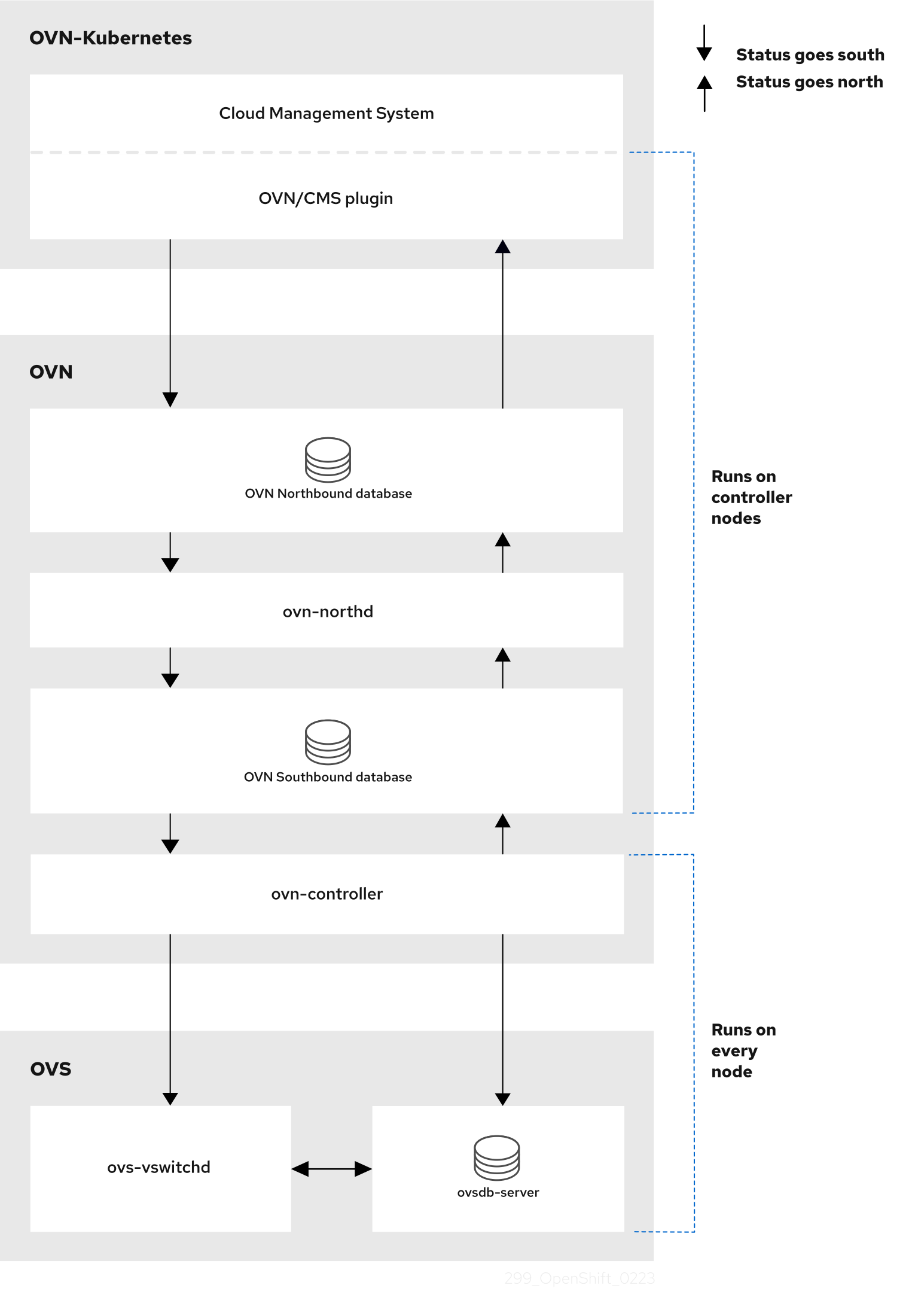
The key components are:
- Cloud Management System (CMS) - A platform specific client for OVN that provides a CMS specific plugin for OVN integration. The plugin translates the cloud management system’s concept of the logical network configuration, stored in the CMS configuration database in a CMS-specific format, into an intermediate representation understood by OVN.
-
OVN Northbound database (
nbdb) container - Stores the logical network configuration passed by the CMS plugin. -
OVN Southbound database (
sbdb) container - Stores the physical and logical network configuration state for Open vSwitch (OVS) system on each node, including tables that bind them. -
OVN north daemon (
ovn-northd) - This is the intermediary client betweennbdbcontainer andsbdbcontainer. It translates the logical network configuration in terms of conventional network concepts, taken from thenbdbcontainer, into logical data path flows in thesbdbcontainer. The container name forovn-northddaemon isnorthdand it runs in theovnkube-nodepods. -
ovn-controller - This is the OVN agent that interacts with OVS and hypervisors, for any information or update that is needed for
sbdbcontainer. Theovn-controllerreads logical flows from thesbdbcontainer, translates them intoOpenFlowflows and sends them to the node’s OVS daemon. The container name isovn-controllerand it runs in theovnkube-nodepods.
The OVN northd, northbound database, and southbound database run on each node in the cluster and mostly contain and process information that is local to that node.
The OVN northbound database has the logical network configuration passed down to it by the cloud management system (CMS). The OVN northbound database contains the current desired state of the network, presented as a collection of logical ports, logical switches, logical routers, and more. The ovn-northd (northd container) connects to the OVN northbound database and the OVN southbound database. It translates the logical network configuration in terms of conventional network concepts, taken from the OVN northbound database, into logical data path flows in the OVN southbound database.
The OVN southbound database has physical and logical representations of the network and binding tables that link them together. It contains the chassis information of the node and other constructs like remote transit switch ports that are required to connect to the other nodes in the cluster. The OVN southbound database also contains all the logic flows. The logic flows are shared with the ovn-controller process that runs on each node and the ovn-controller turns those into OpenFlow rules to program Open vSwitch(OVS).
The Kubernetes control plane nodes contain two ovnkube-control-plane pods on separate nodes, which perform the central IP address management (IPAM) allocation for each node in the cluster. At any given time, a single ovnkube-control-plane pod is the leader.
2.2. Listing all resources in the OVN-Kubernetes project
Finding the resources and containers that run in the OVN-Kubernetes project is important to help you understand the OVN-Kubernetes networking implementation.
Prerequisites
-
Access to the cluster as a user with the
cluster-adminrole. -
The OpenShift CLI (
oc) installed.
Procedure
Run the following command to get all resources, endpoints, and
ConfigMapsin the OVN-Kubernetes project:oc get all,ep,cm -n openshift-ovn-kubernetes
$ oc get all,ep,cm -n openshift-ovn-kubernetesCopy to Clipboard Copied! Toggle word wrap Toggle overflow Example output
Copy to Clipboard Copied! Toggle word wrap Toggle overflow There is one
ovnkube-nodepod for each node in the cluster. Theovnkube-configconfig map has the OpenShift Container Platform OVN-Kubernetes configurations.List all of the containers in the
ovnkube-nodepods by running the following command:oc get pods ovnkube-node-bcvts -o jsonpath='{.spec.containers[*].name}' -n openshift-ovn-kubernetes$ oc get pods ovnkube-node-bcvts -o jsonpath='{.spec.containers[*].name}' -n openshift-ovn-kubernetesCopy to Clipboard Copied! Toggle word wrap Toggle overflow Expected output
ovn-controller ovn-acl-logging kube-rbac-proxy-node kube-rbac-proxy-ovn-metrics northd nbdb sbdb ovnkube-controller
ovn-controller ovn-acl-logging kube-rbac-proxy-node kube-rbac-proxy-ovn-metrics northd nbdb sbdb ovnkube-controllerCopy to Clipboard Copied! Toggle word wrap Toggle overflow The
ovnkube-nodepod is made up of several containers. It is responsible for hosting the northbound database (nbdbcontainer), the southbound database (sbdbcontainer), the north daemon (northdcontainer),ovn-controllerand theovnkube-controllercontainer. Theovnkube-controllercontainer watches for API objects like pods, egress IPs, namespaces, services, endpoints, egress firewall, and network policies. It is also responsible for allocating pod IP from the available subnet pool for that node.List all the containers in the
ovnkube-control-planepods by running the following command:oc get pods ovnkube-control-plane-65c6f55656-6d55h -o jsonpath='{.spec.containers[*].name}' -n openshift-ovn-kubernetes$ oc get pods ovnkube-control-plane-65c6f55656-6d55h -o jsonpath='{.spec.containers[*].name}' -n openshift-ovn-kubernetesCopy to Clipboard Copied! Toggle word wrap Toggle overflow Expected output
kube-rbac-proxy ovnkube-cluster-manager
kube-rbac-proxy ovnkube-cluster-managerCopy to Clipboard Copied! Toggle word wrap Toggle overflow The
ovnkube-control-planepod has a container (ovnkube-cluster-manager) that resides on each OpenShift Container Platform node. Theovnkube-cluster-managercontainer allocates pod subnet, transit switch subnet IP and join switch subnet IP to each node in the cluster. Thekube-rbac-proxycontainer monitors metrics for theovnkube-cluster-managercontainer.
2.3. Listing the OVN-Kubernetes northbound database contents
Each node is controlled by the ovnkube-controller container running in the ovnkube-node pod on that node. To understand the OVN logical networking entities you need to examine the northbound database that is running as a container inside the ovnkube-node pod on that node to see what objects are in the node you wish to see.
Prerequisites
-
Access to the cluster as a user with the
cluster-adminrole. -
The OpenShift CLI (
oc) installed.
To run ovn nbctl or sbctl commands in a cluster you must open a remote shell into the nbdb or sbdb containers on the relevant node
List pods by running the following command:
oc get po -n openshift-ovn-kubernetes
$ oc get po -n openshift-ovn-kubernetesCopy to Clipboard Copied! Toggle word wrap Toggle overflow Example output
Copy to Clipboard Copied! Toggle word wrap Toggle overflow Optional: To list the pods with node information, run the following command:
oc get pods -n openshift-ovn-kubernetes -owide
$ oc get pods -n openshift-ovn-kubernetes -owideCopy to Clipboard Copied! Toggle word wrap Toggle overflow Example output
Copy to Clipboard Copied! Toggle word wrap Toggle overflow Navigate into a pod to look at the northbound database by running the following command:
oc rsh -c nbdb -n openshift-ovn-kubernetes ovnkube-node-55xs2
$ oc rsh -c nbdb -n openshift-ovn-kubernetes ovnkube-node-55xs2Copy to Clipboard Copied! Toggle word wrap Toggle overflow Run the following command to show all the objects in the northbound database:
ovn-nbctl show
$ ovn-nbctl showCopy to Clipboard Copied! Toggle word wrap Toggle overflow The output is too long to list here. The list includes the NAT rules, logical switches, load balancers and so on.
You can narrow down and focus on specific components by using some of the following optional commands:
Run the following command to show the list of logical routers:
oc exec -n openshift-ovn-kubernetes -it ovnkube-node-55xs2 \
-c northd -- ovn-nbctl lr-list
$ oc exec -n openshift-ovn-kubernetes -it ovnkube-node-55xs2 \
-c northd -- ovn-nbctl lr-list
Copy to Clipboard Copied! Toggle word wrap Toggle overflow Example output
45339f4f-7d0b-41d0-b5f9-9fca9ce40ce6 (GR_ci-ln-t487nnb-72292-mdcnq-master-2)
96a0a0f0-e7ed-4fec-8393-3195563de1b8 (ovn_cluster_router)
45339f4f-7d0b-41d0-b5f9-9fca9ce40ce6 (GR_ci-ln-t487nnb-72292-mdcnq-master-2)
96a0a0f0-e7ed-4fec-8393-3195563de1b8 (ovn_cluster_router)
Copy to Clipboard Copied! Toggle word wrap Toggle overflow NoteFrom this output you can see there is router on each node plus an
ovn_cluster_router.Run the following command to show the list of logical switches:
oc exec -n openshift-ovn-kubernetes -it ovnkube-node-55xs2 \
-c nbdb -- ovn-nbctl ls-list
$ oc exec -n openshift-ovn-kubernetes -it ovnkube-node-55xs2 \
-c nbdb -- ovn-nbctl ls-list
Copy to Clipboard Copied! Toggle word wrap Toggle overflow Example output
bdd7dc3d-d848-4a74-b293-cc15128ea614 (ci-ln-t487nnb-72292-mdcnq-master-2)
b349292d-ee03-4914-935f-1940b6cb91e5 (ext_ci-ln-t487nnb-72292-mdcnq-master-2)
0aac0754-ea32-4e33-b086-35eeabf0a140 (join)
992509d7-2c3f-4432-88db-c179e43592e5 (transit_switch)
bdd7dc3d-d848-4a74-b293-cc15128ea614 (ci-ln-t487nnb-72292-mdcnq-master-2)
b349292d-ee03-4914-935f-1940b6cb91e5 (ext_ci-ln-t487nnb-72292-mdcnq-master-2)
0aac0754-ea32-4e33-b086-35eeabf0a140 (join)
992509d7-2c3f-4432-88db-c179e43592e5 (transit_switch)
Copy to Clipboard Copied! Toggle word wrap Toggle overflow NoteFrom this output you can see there is an ext switch for each node plus switches with the node name itself and a join switch.
Run the following command to show the list of load balancers:
oc exec -n openshift-ovn-kubernetes -it ovnkube-node-55xs2 \
-c nbdb -- ovn-nbctl lb-list
$ oc exec -n openshift-ovn-kubernetes -it ovnkube-node-55xs2 \
-c nbdb -- ovn-nbctl lb-list
Copy to Clipboard Copied! Toggle word wrap Toggle overflow Example output
Copy to Clipboard Copied! Toggle word wrap Toggle overflow NoteFrom this truncated output you can see there are many OVN-Kubernetes load balancers. Load balancers in OVN-Kubernetes are representations of services.
Run the following command to display the options available with the command
ovn-nbctl:oc exec -n openshift-ovn-kubernetes -it ovnkube-node-55xs2 \ -c nbdb ovn-nbctl --help
$ oc exec -n openshift-ovn-kubernetes -it ovnkube-node-55xs2 \
-c nbdb ovn-nbctl --help
Copy to Clipboard Copied! Toggle word wrap Toggle overflow
2.4. Command-line arguments for ovn-nbctl to examine northbound database contents
The following table describes the command-line arguments that can be used with ovn-nbctl to examine the contents of the northbound database.
Open a remote shell in the pod you want to view the contents of and then run the ovn-nbctl commands.
| Argument | Description |
|---|---|
|
| An overview of the northbound database contents as seen from a specific node. |
|
| Show the details associated with the specified switch or router. |
|
| Show the logical routers. |
|
|
Using the router information from |
|
| Show network address translation details for the specified router. |
|
| Show the logical switches |
|
|
Using the switch information from |
|
| Get the type for the logical port. |
|
| Show the load balancers. |
2.5. Listing the OVN-Kubernetes southbound database contents
Each node is controlled by the ovnkube-controller container running in the ovnkube-node pod on that node. To understand the OVN logical networking entities you need to examine the northbound database that is running as a container inside the ovnkube-node pod on that node to see what objects are in the node you wish to see.
Prerequisites
-
Access to the cluster as a user with the
cluster-adminrole. -
The OpenShift CLI (
oc) installed.
To run ovn nbctl or sbctl commands in a cluster you must open a remote shell into the nbdb or sbdb containers on the relevant node
List the pods by running the following command:
oc get po -n openshift-ovn-kubernetes
$ oc get po -n openshift-ovn-kubernetesCopy to Clipboard Copied! Toggle word wrap Toggle overflow Example output
Copy to Clipboard Copied! Toggle word wrap Toggle overflow Optional: To list the pods with node information, run the following command:
oc get pods -n openshift-ovn-kubernetes -owide
$ oc get pods -n openshift-ovn-kubernetes -owideCopy to Clipboard Copied! Toggle word wrap Toggle overflow Example output
Copy to Clipboard Copied! Toggle word wrap Toggle overflow Navigate into a pod to look at the southbound database:
oc rsh -c sbdb -n openshift-ovn-kubernetes ovnkube-node-55xs2
$ oc rsh -c sbdb -n openshift-ovn-kubernetes ovnkube-node-55xs2Copy to Clipboard Copied! Toggle word wrap Toggle overflow Run the following command to show all the objects in the southbound database:
ovn-sbctl show
$ ovn-sbctl showCopy to Clipboard Copied! Toggle word wrap Toggle overflow Example output
Copy to Clipboard Copied! Toggle word wrap Toggle overflow This detailed output shows the chassis and the ports that are attached to the chassis which in this case are all of the router ports and anything that runs like host networking. Any pods communicate out to the wider network using source network address translation (SNAT). Their IP address is translated into the IP address of the node that the pod is running on and then sent out into the network.
In addition to the chassis information the southbound database has all the logic flows and those logic flows are then sent to the
ovn-controllerrunning on each of the nodes. Theovn-controllertranslates the logic flows into open flow rules and ultimately programsOpenvSwitchso that your pods can then follow open flow rules and make it out of the network.Run the following command to display the options available with the command
ovn-sbctl:oc exec -n openshift-ovn-kubernetes -it ovnkube-node-55xs2 \ -c sbdb ovn-sbctl --help
$ oc exec -n openshift-ovn-kubernetes -it ovnkube-node-55xs2 \
-c sbdb ovn-sbctl --help
Copy to Clipboard Copied! Toggle word wrap Toggle overflow
2.6. Command-line arguments for ovn-sbctl to examine southbound database contents
The following table describes the command-line arguments that can be used with ovn-sbctl to examine the contents of the southbound database.
Open a remote shell in the pod you wish to view the contents of and then run the ovn-sbctl commands.
| Argument | Description |
|---|---|
|
| An overview of the southbound database contents as seen from a specific node. |
|
| List the contents of southbound database for a the specified port . |
|
| List the logical flows. |
2.7. OVN-Kubernetes logical architecture
OVN is a network virtualization solution. It creates logical switches and routers. These switches and routers are interconnected to create any network topologies. When you run ovnkube-trace with the log level set to 2 or 5 the OVN-Kubernetes logical components are exposed. The following diagram shows how the routers and switches are connected in OpenShift Container Platform.
Figure 2.2. OVN-Kubernetes router and switch components

The key components involved in packet processing are:
- Gateway routers
-
Gateway routers sometimes called L3 gateway routers, are typically used between the distributed routers and the physical network. Gateway routers including their logical patch ports are bound to a physical location (not distributed), or chassis. The patch ports on this router are known as l3gateway ports in the ovn-southbound database (
ovn-sbdb). - Distributed logical routers
- Distributed logical routers and the logical switches behind them, to which virtual machines and containers attach, effectively reside on each hypervisor.
- Join local switch
- Join local switches are used to connect the distributed router and gateway routers. It reduces the number of IP addresses needed on the distributed router.
- Logical switches with patch ports
- Logical switches with patch ports are used to virtualize the network stack. They connect remote logical ports through tunnels.
- Logical switches with localnet ports
- Logical switches with localnet ports are used to connect OVN to the physical network. They connect remote logical ports by bridging the packets to directly connected physical L2 segments using localnet ports.
- Patch ports
- Patch ports represent connectivity between logical switches and logical routers and between peer logical routers. A single connection has a pair of patch ports at each such point of connectivity, one on each side.
- l3gateway ports
-
l3gateway ports are the port binding entries in the
ovn-sbdbfor logical patch ports used in the gateway routers. They are called l3gateway ports rather than patch ports just to portray the fact that these ports are bound to a chassis just like the gateway router itself. - localnet ports
-
localnet ports are present on the bridged logical switches that allows a connection to a locally accessible network from each
ovn-controllerinstance. This helps model the direct connectivity to the physical network from the logical switches. A logical switch can only have a single localnet port attached to it.
2.7.1. Installing network-tools on local host
Install network-tools on your local host to make a collection of tools available for debugging OpenShift Container Platform cluster network issues.
Procedure
Clone the
network-toolsrepository onto your workstation with the following command:git clone git@github.com:openshift/network-tools.git
$ git clone git@github.com:openshift/network-tools.gitCopy to Clipboard Copied! Toggle word wrap Toggle overflow Change into the directory for the repository you just cloned:
cd network-tools
$ cd network-toolsCopy to Clipboard Copied! Toggle word wrap Toggle overflow Optional: List all available commands:
./debug-scripts/network-tools -h
$ ./debug-scripts/network-tools -hCopy to Clipboard Copied! Toggle word wrap Toggle overflow
2.7.2. Running network-tools
Get information about the logical switches and routers by running network-tools.
Prerequisites
-
You installed the OpenShift CLI (
oc). -
You are logged in to the cluster as a user with
cluster-adminprivileges. -
You have installed
network-toolson local host.
Procedure
List the routers by running the following command:
./debug-scripts/network-tools ovn-db-run-command ovn-nbctl lr-list
$ ./debug-scripts/network-tools ovn-db-run-command ovn-nbctl lr-listCopy to Clipboard Copied! Toggle word wrap Toggle overflow Example output
944a7b53-7948-4ad2-a494-82b55eeccf87 (GR_ci-ln-54932yb-72292-kd676-worker-c-rzj99)
84bd4a4c-4b0b-4a47-b0cf-a2c32709fc53 (ovn_cluster_router)
944a7b53-7948-4ad2-a494-82b55eeccf87 (GR_ci-ln-54932yb-72292-kd676-worker-c-rzj99)
84bd4a4c-4b0b-4a47-b0cf-a2c32709fc53 (ovn_cluster_router)
Copy to Clipboard Copied! Toggle word wrap Toggle overflow List the localnet ports by running the following command:
./debug-scripts/network-tools ovn-db-run-command \
ovn-sbctl find Port_Binding type=localnet
$ ./debug-scripts/network-tools ovn-db-run-command \
ovn-sbctl find Port_Binding type=localnet
Copy to Clipboard Copied! Toggle word wrap Toggle overflow Example output
Copy to Clipboard Copied! Toggle word wrap Toggle overflow List the
l3gatewayports by running the following command:./debug-scripts/network-tools ovn-db-run-command \ ovn-sbctl find Port_Binding type=l3gateway
$ ./debug-scripts/network-tools ovn-db-run-command \
ovn-sbctl find Port_Binding type=l3gateway
Copy to Clipboard Copied! Toggle word wrap Toggle overflow Example output
Copy to Clipboard Copied! Toggle word wrap Toggle overflow List the patch ports by running the following command:
./debug-scripts/network-tools ovn-db-run-command \
ovn-sbctl find Port_Binding type=patch
$ ./debug-scripts/network-tools ovn-db-run-command \
ovn-sbctl find Port_Binding type=patch
Copy to Clipboard Copied! Toggle word wrap Toggle overflow Example output
Copy to Clipboard Copied! Toggle word wrap Toggle overflow
Chapter 3. Troubleshooting OVN-Kubernetes
OVN-Kubernetes has many sources of built-in health checks and logs. Follow the instructions in these sections to examine your cluster. If a support case is necessary, follow the support guide to collect additional information through a must-gather. Only use the -- gather_network_logs when instructed by support.
3.1. Monitoring OVN-Kubernetes health by using readiness probes
The ovnkube-control-plane and ovnkube-node pods have containers configured with readiness probes.
Prerequisites
-
Access to the OpenShift CLI (
oc). -
You have access to the cluster with
cluster-adminprivileges. -
You have installed
jq.
Procedure
Review the details of the
ovnkube-nodereadiness probe by running the following command:oc get pods -n openshift-ovn-kubernetes -l app=ovnkube-node \ -o json | jq '.items[0].spec.containers[] | .name,.readinessProbe'
$ oc get pods -n openshift-ovn-kubernetes -l app=ovnkube-node \
-o json | jq '.items[0].spec.containers[] | .name,.readinessProbe'
Copy to Clipboard Copied! Toggle word wrap Toggle overflow The readiness probe for the northbound and southbound database containers in the
ovnkube-nodepod checks for the health of the databases and theovnkube-controllercontainer.The
ovnkube-controllercontainer in theovnkube-nodepod has a readiness probe to verify the presence of the OVN-Kubernetes CNI configuration file, the absence of which would indicate that the pod is not running or is not ready to accept requests to configure pods.Show all events including the probe failures, for the namespace by using the following command:
oc get events -n openshift-ovn-kubernetes
$ oc get events -n openshift-ovn-kubernetesCopy to Clipboard Copied! Toggle word wrap Toggle overflow Show the events for just a specific pod:
oc describe pod ovnkube-node-9lqfk -n openshift-ovn-kubernetes
$ oc describe pod ovnkube-node-9lqfk -n openshift-ovn-kubernetesCopy to Clipboard Copied! Toggle word wrap Toggle overflow Show the messages and statuses from the cluster network operator:
oc get co/network -o json | jq '.status.conditions[]'
$ oc get co/network -o json | jq '.status.conditions[]'Copy to Clipboard Copied! Toggle word wrap Toggle overflow Show the
readystatus of each container inovnkube-nodepods by running the following script:for p in $(oc get pods --selector app=ovnkube-node -n openshift-ovn-kubernetes \ -o jsonpath='{range.items[*]}{" "}{.metadata.name}'); do echo === $p ===; \ oc get pods -n openshift-ovn-kubernetes $p -o json | jq '.status.containerStatuses[] | .name, .ready'; \ done$ for p in $(oc get pods --selector app=ovnkube-node -n openshift-ovn-kubernetes \ -o jsonpath='{range.items[*]}{" "}{.metadata.name}'); do echo === $p ===; \ oc get pods -n openshift-ovn-kubernetes $p -o json | jq '.status.containerStatuses[] | .name, .ready'; \ doneCopy to Clipboard Copied! Toggle word wrap Toggle overflow NoteThe expectation is all container statuses are reporting as
true. Failure of a readiness probe sets the status tofalse.
3.2. Viewing OVN-Kubernetes alerts in the console
The Alerting UI provides detailed information about alerts and their governing alerting rules and silences.
Prerequisites
- You have access to the cluster as a developer or as a user with view permissions for the project that you are viewing metrics for.
Procedure (UI)
- In the Administrator perspective, select Observe → Alerting. The three main pages in the Alerting UI in this perspective are the Alerts, Silences, and Alerting Rules pages.
- View the rules for OVN-Kubernetes alerts by selecting Observe → Alerting → Alerting Rules.
3.3. Viewing OVN-Kubernetes alerts in the CLI
You can get information about alerts and their governing alerting rules and silences from the command line.
Prerequisites
-
Access to the cluster as a user with the
cluster-adminrole. -
The OpenShift CLI (
oc) installed. -
You have installed
jq.
Procedure
View active or firing alerts by running the following commands.
Set the alert manager route environment variable by running the following command:
ALERT_MANAGER=$(oc get route alertmanager-main -n openshift-monitoring \
-o jsonpath='{@.spec.host}')
$ ALERT_MANAGER=$(oc get route alertmanager-main -n openshift-monitoring \ -o jsonpath='{@.spec.host}')Copy to Clipboard Copied! Toggle word wrap Toggle overflow Issue a
curlrequest to the alert manager route API by running the following command, replacing$ALERT_MANAGERwith the URL of yourAlertmanagerinstance:curl -s -k -H "Authorization: Bearer $(oc create token prometheus-k8s -n openshift-monitoring)" https://$ALERT_MANAGER/api/v1/alerts | jq '.data[] | "\(.labels.severity) \(.labels.alertname) \(.labels.pod) \(.labels.container) \(.labels.endpoint) \(.labels.instance)"'
$ curl -s -k -H "Authorization: Bearer $(oc create token prometheus-k8s -n openshift-monitoring)" https://$ALERT_MANAGER/api/v1/alerts | jq '.data[] | "\(.labels.severity) \(.labels.alertname) \(.labels.pod) \(.labels.container) \(.labels.endpoint) \(.labels.instance)"'Copy to Clipboard Copied! Toggle word wrap Toggle overflow
View alerting rules by running the following command:
oc -n openshift-monitoring exec -c prometheus prometheus-k8s-0 -- curl -s 'http://localhost:9090/api/v1/rules' | jq '.data.groups[].rules[] | select(((.name|contains("ovn")) or (.name|contains("OVN")) or (.name|contains("Ovn")) or (.name|contains("North")) or (.name|contains("South"))) and .type=="alerting")'$ oc -n openshift-monitoring exec -c prometheus prometheus-k8s-0 -- curl -s 'http://localhost:9090/api/v1/rules' | jq '.data.groups[].rules[] | select(((.name|contains("ovn")) or (.name|contains("OVN")) or (.name|contains("Ovn")) or (.name|contains("North")) or (.name|contains("South"))) and .type=="alerting")'Copy to Clipboard Copied! Toggle word wrap Toggle overflow
3.4. Viewing the OVN-Kubernetes logs using the CLI
You can view the logs for each of the pods in the ovnkube-master and ovnkube-node pods using the OpenShift CLI (oc).
Prerequisites
-
Access to the cluster as a user with the
cluster-adminrole. -
Access to the OpenShift CLI (
oc). -
You have installed
jq.
Procedure
View the log for a specific pod:
oc logs -f <pod_name> -c <container_name> -n <namespace>
$ oc logs -f <pod_name> -c <container_name> -n <namespace>Copy to Clipboard Copied! Toggle word wrap Toggle overflow where:
-f- Optional: Specifies that the output follows what is being written into the logs.
<pod_name>- Specifies the name of the pod.
<container_name>- Optional: Specifies the name of a container. When a pod has more than one container, you must specify the container name.
<namespace>- Specify the namespace the pod is running in.
For example:
oc logs ovnkube-node-5dx44 -n openshift-ovn-kubernetes
$ oc logs ovnkube-node-5dx44 -n openshift-ovn-kubernetesCopy to Clipboard Copied! Toggle word wrap Toggle overflow oc logs -f ovnkube-node-5dx44 -c ovnkube-controller -n openshift-ovn-kubernetes
$ oc logs -f ovnkube-node-5dx44 -c ovnkube-controller -n openshift-ovn-kubernetesCopy to Clipboard Copied! Toggle word wrap Toggle overflow The contents of log files are printed out.
Examine the most recent entries in all the containers in the
ovnkube-nodepods:for p in $(oc get pods --selector app=ovnkube-node -n openshift-ovn-kubernetes \ -o jsonpath='{range.items[*]}{" "}{.metadata.name}'); \ do echo === $p ===; for container in $(oc get pods -n openshift-ovn-kubernetes $p \ -o json | jq -r '.status.containerStatuses[] | .name');do echo ---$container---; \ oc logs -c $container $p -n openshift-ovn-kubernetes --tail=5; done; done$ for p in $(oc get pods --selector app=ovnkube-node -n openshift-ovn-kubernetes \ -o jsonpath='{range.items[*]}{" "}{.metadata.name}'); \ do echo === $p ===; for container in $(oc get pods -n openshift-ovn-kubernetes $p \ -o json | jq -r '.status.containerStatuses[] | .name');do echo ---$container---; \ oc logs -c $container $p -n openshift-ovn-kubernetes --tail=5; done; doneCopy to Clipboard Copied! Toggle word wrap Toggle overflow View the last 5 lines of every log in every container in an
ovnkube-nodepod using the following command:oc logs -l app=ovnkube-node -n openshift-ovn-kubernetes --all-containers --tail 5
$ oc logs -l app=ovnkube-node -n openshift-ovn-kubernetes --all-containers --tail 5Copy to Clipboard Copied! Toggle word wrap Toggle overflow
3.5. Viewing the OVN-Kubernetes logs using the web console
You can view the logs for each of the pods in the ovnkube-master and ovnkube-node pods in the web console.
Prerequisites
-
Access to the OpenShift CLI (
oc).
Procedure
- In the OpenShift Container Platform console, navigate to Workloads → Pods or navigate to the pod through the resource you want to investigate.
-
Select the
openshift-ovn-kubernetesproject from the drop-down menu. - Click the name of the pod you want to investigate.
-
Click Logs. By default for the
ovnkube-masterthe logs associated with thenorthdcontainer are displayed. - Use the down-down menu to select logs for each container in turn.
3.5.1. Changing the OVN-Kubernetes log levels
The default log level for OVN-Kubernetes is 4. To debug OVN-Kubernetes, set the log level to 5. Follow this procedure to increase the log level of the OVN-Kubernetes to help you debug an issue.
Prerequisites
-
You have access to the cluster with
cluster-adminprivileges. - You have access to the OpenShift Container Platform web console.
Procedure
Run the following command to get detailed information for all pods in the OVN-Kubernetes project:
oc get po -o wide -n openshift-ovn-kubernetes
$ oc get po -o wide -n openshift-ovn-kubernetesCopy to Clipboard Copied! Toggle word wrap Toggle overflow Example output
Copy to Clipboard Copied! Toggle word wrap Toggle overflow Create a
ConfigMapfile similar to the following example and use a filename such asenv-overrides.yaml:Example
ConfigMapfileCopy to Clipboard Copied! Toggle word wrap Toggle overflow Apply the
ConfigMapfile by using the following command:oc apply -n openshift-ovn-kubernetes -f env-overrides.yaml
$ oc apply -n openshift-ovn-kubernetes -f env-overrides.yamlCopy to Clipboard Copied! Toggle word wrap Toggle overflow Example output
configmap/env-overrides.yaml created
configmap/env-overrides.yaml createdCopy to Clipboard Copied! Toggle word wrap Toggle overflow Restart the
ovnkubepods to apply the new log level by using the following commands:oc delete pod -n openshift-ovn-kubernetes \ --field-selector spec.nodeName=ci-ln-3njdr9b-72292-5nwkp-master-0 -l app=ovnkube-node
$ oc delete pod -n openshift-ovn-kubernetes \
--field-selector spec.nodeName=ci-ln-3njdr9b-72292-5nwkp-master-0 -l app=ovnkube-node
Copy to Clipboard Copied! Toggle word wrap Toggle overflow oc delete pod -n openshift-ovn-kubernetes \ --field-selector spec.nodeName=ci-ln-3njdr9b-72292-5nwkp-master-2 -l app=ovnkube-node
$ oc delete pod -n openshift-ovn-kubernetes \
--field-selector spec.nodeName=ci-ln-3njdr9b-72292-5nwkp-master-2 -l app=ovnkube-node
Copy to Clipboard Copied! Toggle word wrap Toggle overflow oc delete pod -n openshift-ovn-kubernetes -l app=ovnkube-node
$ oc delete pod -n openshift-ovn-kubernetes -l app=ovnkube-nodeCopy to Clipboard Copied! Toggle word wrap Toggle overflow To verify that the `ConfigMap`file has been applied to all nodes for a specific pod, run the following command:
oc logs -n openshift-ovn-kubernetes --all-containers --prefix ovnkube-node-<xxxx> | grep -E -m 10 '(Logging config:|vconsole|DBG)'
$ oc logs -n openshift-ovn-kubernetes --all-containers --prefix ovnkube-node-<xxxx> | grep -E -m 10 '(Logging config:|vconsole|DBG)'Copy to Clipboard Copied! Toggle word wrap Toggle overflow where:
<XXXX>Specifies the random sequence of letters for a pod from the previous step.
Example output
Copy to Clipboard Copied! Toggle word wrap Toggle overflow
Optional: Check the
ConfigMapfile has been applied by running the following command:for f in $(oc -n openshift-ovn-kubernetes get po -l 'app=ovnkube-node' --no-headers -o custom-columns=N:.metadata.name) ; do echo "---- $f ----" ; oc -n openshift-ovn-kubernetes exec -c ovnkube-controller $f -- pgrep -a -f init-ovnkube-controller | grep -P -o '^.*loglevel\s+\d' ; done
for f in $(oc -n openshift-ovn-kubernetes get po -l 'app=ovnkube-node' --no-headers -o custom-columns=N:.metadata.name) ; do echo "---- $f ----" ; oc -n openshift-ovn-kubernetes exec -c ovnkube-controller $f -- pgrep -a -f init-ovnkube-controller | grep -P -o '^.*loglevel\s+\d' ; doneCopy to Clipboard Copied! Toggle word wrap Toggle overflow Example output
Copy to Clipboard Copied! Toggle word wrap Toggle overflow
3.6. Checking the OVN-Kubernetes pod network connectivity
The connectivity check controller, in OpenShift Container Platform 4.10 and later, orchestrates connection verification checks in your cluster. These include Kubernetes API, OpenShift API and individual nodes. The results for the connection tests are stored in PodNetworkConnectivity objects in the openshift-network-diagnostics namespace. Connection tests are performed every minute in parallel.
Prerequisites
-
Access to the OpenShift CLI (
oc). -
Access to the cluster as a user with the
cluster-adminrole. -
You have installed
jq.
Procedure
To list the current
PodNetworkConnectivityCheckobjects, enter the following command:oc get podnetworkconnectivitychecks -n openshift-network-diagnostics
$ oc get podnetworkconnectivitychecks -n openshift-network-diagnosticsCopy to Clipboard Copied! Toggle word wrap Toggle overflow View the most recent success for each connection object by using the following command:
oc get podnetworkconnectivitychecks -n openshift-network-diagnostics \
-o json | jq '.items[]| .spec.targetEndpoint,.status.successes[0]'
$ oc get podnetworkconnectivitychecks -n openshift-network-diagnostics \
-o json | jq '.items[]| .spec.targetEndpoint,.status.successes[0]'
Copy to Clipboard Copied! Toggle word wrap Toggle overflow View the most recent failures for each connection object by using the following command:
oc get podnetworkconnectivitychecks -n openshift-network-diagnostics \
-o json | jq '.items[]| .spec.targetEndpoint,.status.failures[0]'
$ oc get podnetworkconnectivitychecks -n openshift-network-diagnostics \
-o json | jq '.items[]| .spec.targetEndpoint,.status.failures[0]'
Copy to Clipboard Copied! Toggle word wrap Toggle overflow View the most recent outages for each connection object by using the following command:
oc get podnetworkconnectivitychecks -n openshift-network-diagnostics \
-o json | jq '.items[]| .spec.targetEndpoint,.status.outages[0]'
$ oc get podnetworkconnectivitychecks -n openshift-network-diagnostics \
-o json | jq '.items[]| .spec.targetEndpoint,.status.outages[0]'
Copy to Clipboard Copied! Toggle word wrap Toggle overflow The connectivity check controller also logs metrics from these checks into Prometheus.
View all the metrics by running the following command:
oc exec prometheus-k8s-0 -n openshift-monitoring -- \
promtool query instant  http://localhost:9090 \
'{component="openshift-network-diagnostics"}'
$ oc exec prometheus-k8s-0 -n openshift-monitoring -- \ promtool query instant http://localhost:9090 \ '{component="openshift-network-diagnostics"}'Copy to Clipboard Copied! Toggle word wrap Toggle overflow View the latency between the source pod and the openshift api service for the last 5 minutes:
oc exec prometheus-k8s-0 -n openshift-monitoring -- \
promtool query instant  http://localhost:9090 \
'{component="openshift-network-diagnostics"}'
$ oc exec prometheus-k8s-0 -n openshift-monitoring -- \ promtool query instant http://localhost:9090 \ '{component="openshift-network-diagnostics"}'Copy to Clipboard Copied! Toggle word wrap Toggle overflow
3.7. Checking OVN-Kubernetes network traffic with OVS sampling using the CLI
Checking OVN-Kubernetes network traffic with OVS sampling is a Technology Preview feature only. Technology Preview features are not supported with Red Hat production service level agreements (SLAs) and might not be functionally complete. Red Hat does not recommend using them in production. These features provide early access to upcoming product features, enabling customers to test functionality and provide feedback during the development process.
For more information about the support scope of Red Hat Technology Preview features, see Technology Preview Features Support Scope.
OVN-Kubernetes network traffic can be viewed with OVS sampling via the CLI for the following network APIs:
-
NetworkPolicy -
AdminNetworkPolicy -
BaselineNetworkPolicy -
UserDefinedNetworkisolation -
EgressFirewall - Multicast ACLs.
Scripts for these networking events are found in the /usr/bin/ovnkube-observ path of each OVN-Kubernetes node.
Although both the Network Observability Operator and checking OVN-Kubernetes network traffic with OVS sampling are good for debuggability, the Network Observability Operator is intended for observing network events. Alternatively, checking OVN-Kubernetes network traffic with OVS sampling using the CLI is intended to help with packet tracing; it can also be used while the Network Observability Operator is installed, however that is not a requirement.
Administrators can add the --add-ovs-collect option to view network traffic across the node, or pass in additional flags to filter result for specific pods. Additional flags can be found in the "OVN-Kubernetes network traffic with OVS sampling flags" section.
Use the following procedure to view OVN-Kubernetes network traffic using the CLI.
Prerequisites
-
You are logged in to the cluster as a user with
cluster-adminprivileges. - You have created a source pod and a destination pod and ran traffic between them.
-
You have created at least one of the following network APIs:
NetworkPolicy,AdminNetworkPolicy,BaselineNetworkPolicy,UserDefinedNetworkisolation, multicast, or egress firewalls.
Procedure
To enable the
OVNObservabilitywith OVS sampling feature, enableTechPreviewNoUpgradefeature set in theFeatureGateCR namedclusterby entering the following command:oc patch --type=merge --patch '{"spec": {"featureSet": "TechPreviewNoUpgrade"}}' featuregate/cluster$ oc patch --type=merge --patch '{"spec": {"featureSet": "TechPreviewNoUpgrade"}}' featuregate/clusterCopy to Clipboard Copied! Toggle word wrap Toggle overflow Example output
featuregate.config.openshift.io/cluster patched
featuregate.config.openshift.io/cluster patchedCopy to Clipboard Copied! Toggle word wrap Toggle overflow Confirm that the
OVNObservabilityfeature is enabled by entering the following command:oc get featuregate cluster -o yaml
$ oc get featuregate cluster -o yamlCopy to Clipboard Copied! Toggle word wrap Toggle overflow Example output
featureGates: # ... enabled: - name: OVNObservabilityfeatureGates: # ... enabled: - name: OVNObservabilityCopy to Clipboard Copied! Toggle word wrap Toggle overflow Obtain a list of the pods inside of the namespace in which you have created one of the relevant network APIs by entering the following command. Note the
NODEname of the pods, as they are used in the following step.oc get pods -n <namespace> -o wide
$ oc get pods -n <namespace> -o wideCopy to Clipboard Copied! Toggle word wrap Toggle overflow Example output
NAME              READY   STATUS    RESTARTS   AGE     IP            NODE                                       NOMINATED NODE   READINESS GATES
destination-pod   1/1     Running   0          53s     10.131.0.23   ci-ln-1gqp7b2-72292-bb9dv-worker-a-gtmpc   <none>           <none>
source-pod        1/1     Running   0          56s     10.131.0.22   ci-ln-1gqp7b2-72292-bb9dv-worker-a-gtmpc   <none>           <none>
Copy to Clipboard Copied! Toggle word wrap Toggle overflow Obtain a list of OVN-Kubernetes pods and locate the pod that shares the same
NODEas the pods from the previous step by entering the following command:oc get pods -n openshift-ovn-kubernetes -o wide
$ oc get pods -n openshift-ovn-kubernetes -o wideCopy to Clipboard Copied! Toggle word wrap Toggle overflow Example output
NAME
...                             READY   STATUS    RESTARTS      AGE   IP           NODE                                       NOMINATED NODE
ovnkube-node-jzn5b              8/8     Running   1 (34m ago)   37m   10.0.128.2   ci-ln-1gqp7b2-72292-bb9dv-worker-a-gtmpc   <none>
...
NAME
...                             READY   STATUS    RESTARTS      AGE   IP           NODE                                       NOMINATED NODE
ovnkube-node-jzn5b              8/8     Running   1 (34m ago)   37m   10.0.128.2   ci-ln-1gqp7b2-72292-bb9dv-worker-a-gtmpc   <none>
...
Copy to Clipboard Copied! Toggle word wrap Toggle overflow Open a bash shell inside of the
ovnkube-nodepod by entering the following command:oc exec -it <pod_name> -n openshift-ovn-kubernetes -- bash
$ oc exec -it <pod_name> -n openshift-ovn-kubernetes -- bashCopy to Clipboard Copied! Toggle word wrap Toggle overflow While inside of the
ovnkube-nodepod, you can run theovnkube-observ -add-ovs-collectorscript to show network events using the OVS collector. For example:/usr/bin/ovnkube-observ -add-ovs-collector
# /usr/bin/ovnkube-observ -add-ovs-collectorCopy to Clipboard Copied! Toggle word wrap Toggle overflow Example output
Copy to Clipboard Copied! Toggle word wrap Toggle overflow You can filter the content by type, such as source pods, by entering the following command with the
-filter-src-ipflag and your pod’s IP address. For example:/usr/bin/ovnkube-observ -add-ovs-collector -filter-src-ip <pod_ip_address>
# /usr/bin/ovnkube-observ -add-ovs-collector -filter-src-ip <pod_ip_address>Copy to Clipboard Copied! Toggle word wrap Toggle overflow Example output
Copy to Clipboard Copied! Toggle word wrap Toggle overflow For a full list of flags that can be passed in with
/usr/bin/ovnkube-observ, see "OVN-Kubernetes network traffic with OVS sampling flags".
3.7.1. OVN-Kubernetes network traffic with OVS sampling flags
The following flags are available to view OVN-Kubernetes network traffic by using the CLI. Append these flags to the following syntax in your terminal after you have opened a bash shell inside of the ovnkube-node pod:
Command syntax
/usr/bin/ovnkube-observ <flag>
# /usr/bin/ovnkube-observ <flag>| Flag | Description |
|---|---|
|
|
Returns a complete list flags that can be used with the |
|
| Add OVS collector to enable sampling. Use with caution. Make sure no one else is using observability. |
|
|
Enrich samples with NBDB data. Defaults to |
|
| Filter only packets to a given destination IP. |
|
| Filters only packets from a given source IP. |
|
| Print raw sample cookie with psample group_id. |
|
| Output file to write the samples to. |
|
| Print full received packet. When false, only source and destination IPs are printed with every sample. |
Chapter 4. Tracing Openflow with ovnkube-trace
OVN and OVS traffic flows can be simulated in a single utility called ovnkube-trace. The ovnkube-trace utility runs ovn-trace, ovs-appctl ofproto/trace and ovn-detrace and correlates that information in a single output.
You can execute the ovnkube-trace binary from a dedicated container. For releases after OpenShift Container Platform 4.7, you can also copy the binary to a local host and execute it from that host.
4.1. Installing the ovnkube-trace on local host
The ovnkube-trace tool traces packet simulations for arbitrary UDP or TCP traffic between points in an OVN-Kubernetes driven OpenShift Container Platform cluster. Copy the ovnkube-trace binary to your local host making it available to run against the cluster.
Prerequisites
-
You installed the OpenShift CLI (
oc). -
You are logged in to the cluster with a user with
cluster-adminprivileges.
Procedure
Create a pod variable by using the following command:
POD=$(oc get pods -n openshift-ovn-kubernetes -l app=ovnkube-control-plane -o name | head -1 | awk -F '/' '{print $NF}')$ POD=$(oc get pods -n openshift-ovn-kubernetes -l app=ovnkube-control-plane -o name | head -1 | awk -F '/' '{print $NF}')Copy to Clipboard Copied! Toggle word wrap Toggle overflow Run the following command on your local host to copy the binary from the
ovnkube-control-planepods:oc cp -n openshift-ovn-kubernetes $POD:/usr/bin/ovnkube-trace -c ovnkube-cluster-manager ovnkube-trace
$ oc cp -n openshift-ovn-kubernetes $POD:/usr/bin/ovnkube-trace -c ovnkube-cluster-manager ovnkube-traceCopy to Clipboard Copied! Toggle word wrap Toggle overflow NoteIf you are using Red Hat Enterprise Linux (RHEL) 8 to run the
ovnkube-tracetool, you must copy the file/usr/lib/rhel8/ovnkube-traceto your local host.Make
ovnkube-traceexecutable by running the following command:chmod +x ovnkube-trace
$ chmod +x ovnkube-traceCopy to Clipboard Copied! Toggle word wrap Toggle overflow Display the options available with
ovnkube-traceby running the following command:./ovnkube-trace -help
$ ./ovnkube-trace -helpCopy to Clipboard Copied! Toggle word wrap Toggle overflow Expected output
Copy to Clipboard Copied! Toggle word wrap Toggle overflow The command-line arguments supported are familiar Kubernetes constructs, such as namespaces, pods, services so you do not need to find the MAC address, the IP address of the destination nodes, or the ICMP type.
The log levels are:
- 0 (minimal output)
- 2 (more verbose output showing results of trace commands)
- 5 (debug output)
4.2. Running ovnkube-trace
Run ovn-trace to simulate packet forwarding within an OVN logical network.
Prerequisites
-
You installed the OpenShift CLI (
oc). -
You are logged in to the cluster with a user with
cluster-adminprivileges. -
You have installed
ovnkube-traceon local host
Example: Testing that DNS resolution works from a deployed pod
This example illustrates how to test the DNS resolution from a deployed pod to the core DNS pod that runs in the cluster.
Procedure
Start a web service in the default namespace by entering the following command:
oc run web --namespace=default --image=quay.io/openshifttest/nginx --labels="app=web" --expose --port=80
$ oc run web --namespace=default --image=quay.io/openshifttest/nginx --labels="app=web" --expose --port=80Copy to Clipboard Copied! Toggle word wrap Toggle overflow List the pods running in the
openshift-dnsnamespace:oc get pods -n openshift-dns
oc get pods -n openshift-dnsCopy to Clipboard Copied! Toggle word wrap Toggle overflow Example output
Copy to Clipboard Copied! Toggle word wrap Toggle overflow Run the following
ovnkube-tracecommand to verify DNS resolution is working:Copy to Clipboard Copied! Toggle word wrap Toggle overflow Example output if the
src&dstpod lands on the same nodeCopy to Clipboard Copied! Toggle word wrap Toggle overflow Example output if the
src&dstpod lands on a different nodeCopy to Clipboard Copied! Toggle word wrap Toggle overflow The ouput indicates success from the deployed pod to the DNS port and also indicates that it is successful going back in the other direction. So you know bi-directional traffic is supported on UDP port 53 if my web pod wants to do dns resolution from core DNS.
If for example that did not work and you wanted to get the ovn-trace, the ovs-appctl of proto/trace and ovn-detrace, and more debug type information increase the log level to 2 and run the command again as follows:
The output from this increased log level is too much to list here. In a failure situation the output of this command shows which flow is dropping that traffic. For example an egress or ingress network policy may be configured on the cluster that does not allow that traffic.
Example: Verifying by using debug output a configured default deny
This example illustrates how to identify by using the debug output that an ingress default deny policy blocks traffic.
Procedure
Create the following YAML that defines a
deny-by-defaultpolicy to deny ingress from all pods in all namespaces. Save the YAML in thedeny-by-default.yamlfile:Copy to Clipboard Copied! Toggle word wrap Toggle overflow Apply the policy by entering the following command:
oc apply -f deny-by-default.yaml
$ oc apply -f deny-by-default.yamlCopy to Clipboard Copied! Toggle word wrap Toggle overflow Example output
networkpolicy.networking.k8s.io/deny-by-default created
networkpolicy.networking.k8s.io/deny-by-default createdCopy to Clipboard Copied! Toggle word wrap Toggle overflow Start a web service in the
defaultnamespace by entering the following command:oc run web --namespace=default --image=quay.io/openshifttest/nginx --labels="app=web" --expose --port=80
$ oc run web --namespace=default --image=quay.io/openshifttest/nginx --labels="app=web" --expose --port=80Copy to Clipboard Copied! Toggle word wrap Toggle overflow Run the following command to create the
prodnamespace:oc create namespace prod
$ oc create namespace prodCopy to Clipboard Copied! Toggle word wrap Toggle overflow Run the following command to label the
prodnamespace:oc label namespace/prod purpose=production
$ oc label namespace/prod purpose=productionCopy to Clipboard Copied! Toggle word wrap Toggle overflow Run the following command to deploy an
alpineimage in theprodnamespace and start a shell:oc run test-6459 --namespace=prod --rm -i -t --image=alpine -- sh
$ oc run test-6459 --namespace=prod --rm -i -t --image=alpine -- shCopy to Clipboard Copied! Toggle word wrap Toggle overflow - Open another terminal session.
In this new terminal session run
ovn-traceto verify the failure in communication between the source podtest-6459running in namespaceprodand destination pod running in thedefaultnamespace:Copy to Clipboard Copied! Toggle word wrap Toggle overflow Example output
ovn-trace source pod to destination pod indicates failure from test-6459 to web
ovn-trace source pod to destination pod indicates failure from test-6459 to webCopy to Clipboard Copied! Toggle word wrap Toggle overflow Increase the log level to 2 to expose the reason for the failure by running the following command:
Copy to Clipboard Copied! Toggle word wrap Toggle overflow Example output
Copy to Clipboard Copied! Toggle word wrap Toggle overflow - 1
- Ingress traffic is blocked due to the default deny policy being in place.
Create a policy that allows traffic from all pods in a particular namespaces with a label
purpose=production. Save the YAML in theweb-allow-prod.yamlfile:Copy to Clipboard Copied! Toggle word wrap Toggle overflow Apply the policy by entering the following command:
oc apply -f web-allow-prod.yaml
$ oc apply -f web-allow-prod.yamlCopy to Clipboard Copied! Toggle word wrap Toggle overflow Run
ovnkube-traceto verify that traffic is now allowed by entering the following command:Copy to Clipboard Copied! Toggle word wrap Toggle overflow Expected output
Copy to Clipboard Copied! Toggle word wrap Toggle overflow Run the following command in the shell that was opened in step six to connect nginx to the web-server:
wget -qO- --timeout=2 http://web.default
wget -qO- --timeout=2 http://web.defaultCopy to Clipboard Copied! Toggle word wrap Toggle overflow Expected output
Copy to Clipboard Copied! Toggle word wrap Toggle overflow
Chapter 5. Converting to IPv4/IPv6 dual-stack networking
As a cluster administrator, you can convert your IPv4 single-stack cluster to a dual-network cluster network that supports IPv4 and IPv6 address families. After converting to dual-stack networking, new and existing pods have dual-stack networking enabled.
When using dual-stack networking where IPv6 is required, you cannot use IPv4-mapped IPv6 addresses, such as ::FFFF:198.51.100.1.
5.1. Converting to a dual-stack cluster network
As a cluster administrator, you can convert your single-stack cluster network to a dual-stack cluster network.
After converting your cluster to use dual-stack networking, you must re-create any existing pods for them to receive IPv6 addresses, because only new pods are assigned IPv6 addresses.
Converting a single-stack cluster network to a dual-stack cluster network consists of creating patches and applying them to the network and infrastructure of the cluster. You can convert to a dual-stack cluster network for a cluster that runs on either installer-provisioned infrastructure or user-provisioned infrastructure.
Each patch operation that changes clusterNetwork, serviceNetwork, apiServerInternalIPs, and ingressIP objects triggers a restart of the cluster. Changing the MachineNetworks object does not cause a reboot of the cluster.
On installer-provisioned infrastructure only, if you need to add IPv6 virtual IPs (VIPs) for API and Ingress services to an existing dual-stack-configured cluster, you need to patch only the infrastructure and not the network for the cluster.
If you already upgraded your cluster to OpenShift Container Platform 4.16 or later and you need to convert the single-stack cluster network to a dual-stack cluster network, you must specify an existing IPv4 machineNetwork network configuration from the install-config.yaml file for API and Ingress services in the YAML configuration patch file. This configuration ensures that IPv4 traffic exists in the same network interface as the default gateway.
Example YAML configuration file with an added IPv4 address block for the machineNetwork network
- op: add
  path: /spec/platformSpec/baremetal/machineNetworks/-
  value: 192.168.1.0/24
  # ...
- op: add
  path: /spec/platformSpec/baremetal/machineNetworks/-
  value: 192.168.1.0/24
# ...- 1
- Ensure that you specify an address block for the
machineNetworknetwork where your machines operate. You must select both API and Ingress IP addresses for the machine network.
Prerequisites
-
You installed the OpenShift CLI (
oc). -
You are logged in to the cluster with a user with
cluster-adminprivileges. - Your cluster uses the OVN-Kubernetes network plugin.
- The cluster nodes have IPv6 addresses.
- You have configured an IPv6-enabled router based on your infrastructure.
Procedure
To specify IPv6 address blocks for cluster and service networks, create a YAML configuration patch file that has a similar configuration to the following example:
Copy to Clipboard Copied! Toggle word wrap Toggle overflow - 1
- Specify an object with the
cidrandhostPrefixparameters. The host prefix must be64or greater. The IPv6 Classless Inter-Domain Routing (CIDR) prefix must be large enough to accommodate the specified host prefix. - 2
- Specify an IPv6 CIDR with a prefix of
112. Kubernetes uses only the lowest 16 bits. For a prefix of112, IP addresses are assigned from112to128bits.
Patch the cluster network configuration by entering the following command in your CLI:
oc patch network.config.openshift.io cluster \
  --type='json' --patch-file <file>.yaml
$ oc patch network.config.openshift.io cluster \1 --type='json' --patch-file <file>.yamlCopy to Clipboard Copied! Toggle word wrap Toggle overflow - 1
- Where
filespecifies the name of your created YAML file.
Example output
network.config.openshift.io/cluster patched
network.config.openshift.io/cluster patchedCopy to Clipboard Copied! Toggle word wrap Toggle overflow On installer-provisioned infrastructure where you added IPv6 VIPs for API and Ingress services, complete the following steps:
Specify IPv6 VIPs for API and Ingress services for your cluster. Create a YAML configuration patch file that has a similar configuration to the following example:
Copy to Clipboard Copied! Toggle word wrap Toggle overflow - 1
- Ensure that you specify an address block for the
machineNetworknetwork where your machines operate. You must select both API and Ingress IP addresses for the machine network. - 2
- Ensure that you specify each file path according to your platform. The example demonstrates a file path on a bare-metal platform.
Patch the infrastructure by entering the following command in your CLI:
oc patch infrastructure cluster \
  --type='json' --patch-file <file>.yaml
$ oc patch infrastructure cluster \
  --type='json' --patch-file <file>.yaml
Copy to Clipboard Copied! Toggle word wrap Toggle overflow Where:
- <file>
Specifies the name of your created YAML file.
Example output
infrastructure/cluster patched
infrastructure/cluster patchedCopy to Clipboard Copied! Toggle word wrap Toggle overflow
Verification
Show the cluster network configuration by entering the following command in your CLI:
oc describe network
$ oc describe networkCopy to Clipboard Copied! Toggle word wrap Toggle overflow Verify the successful installation of the patch on the network configuration by checking that the cluster network configuration recognizes the IPv6 address blocks that you specified in the YAML file.
Example output
Copy to Clipboard Copied! Toggle word wrap Toggle overflow Complete the following additional tasks for a cluster that runs on installer-provisioned infrastructure:
Show the cluster infrastructure configuration by entering the following command in your CLI:
oc describe infrastructure
$ oc describe infrastructureCopy to Clipboard Copied! Toggle word wrap Toggle overflow Verify the successful installation of the patch on the cluster infrastructure by checking that the infrastructure recognizes the IPv6 address blocks that you specified in the YAML file.
Example output
Copy to Clipboard Copied! Toggle word wrap Toggle overflow
5.2. Converting to a single-stack cluster network
As a cluster administrator, you can convert your dual-stack cluster network to a single-stack cluster network.
If you originally converted your IPv4 single-stack cluster network to a dual-stack cluster, you can convert only back to the IPv4 single-stack cluster and not an IPv6 single-stack cluster network. The same restriction applies for converting back to an IPv6 single-stack cluster network.
Prerequisites
-
You installed the OpenShift CLI (
oc). -
You are logged in to the cluster with a user with
cluster-adminprivileges. - Your cluster uses the OVN-Kubernetes network plugin.
- The cluster nodes have IPv6 addresses.
- You have enabled dual-stack networking.
Procedure
Edit the
networks.config.openshift.iocustom resource (CR) by running the following command:oc edit networks.config.openshift.io
$ oc edit networks.config.openshift.ioCopy to Clipboard Copied! Toggle word wrap Toggle overflow -
Remove the IPv4 or IPv6 configuration that you added to the
cidrand thehostPrefixparameters from completing the "Converting to a dual-stack cluster network " procedure steps.
Chapter 6. Configuring OVN-Kubernetes internal IP address subnets
As a cluster administrator, you can change the IP address ranges that the OVN-Kubernetes network plugin uses for the join and transit subnets.
6.1. Configuring the OVN-Kubernetes join subnet
You can change the join subnet used by OVN-Kubernetes to avoid conflicting with any existing subnets already in use in your environment.
Prerequisites
-
Install the OpenShift CLI (
oc). -
Log in to the cluster with a user with
cluster-adminprivileges. - Ensure that the cluster uses the OVN-Kubernetes network plugin.
Procedure
To change the OVN-Kubernetes join subnet, enter the following command:
oc patch network.operator.openshift.io cluster --type='merge' \
  -p='{"spec":{"defaultNetwork":{"ovnKubernetesConfig":
    {"ipv4":{"internalJoinSubnet": "<join_subnet>"},
    "ipv6":{"internalJoinSubnet": "<join_subnet>"}}}}}'
$ oc patch network.operator.openshift.io cluster --type='merge' \ -p='{"spec":{"defaultNetwork":{"ovnKubernetesConfig": {"ipv4":{"internalJoinSubnet": "<join_subnet>"}, "ipv6":{"internalJoinSubnet": "<join_subnet>"}}}}}'Copy to Clipboard Copied! Toggle word wrap Toggle overflow where:
<join_subnet>-
Specifies an IP address subnet for internal use by OVN-Kubernetes. The subnet must be larger than the number of nodes in the cluster and it must be large enough to accommodate one IP address per node in the cluster. This subnet cannot overlap with any other subnets used by OpenShift Container Platform or on the host itself. The default value for IPv4 is
100.64.0.0/16and the default value for IPv6 isfd98::/64.
Example output
network.operator.openshift.io/cluster patched
network.operator.openshift.io/cluster patchedCopy to Clipboard Copied! Toggle word wrap Toggle overflow
Verification
To confirm that the configuration is active, enter the following command:
oc get network.operator.openshift.io \
  -o jsonpath="{.items[0].spec.defaultNetwork}"
$ oc get network.operator.openshift.io \ -o jsonpath="{.items[0].spec.defaultNetwork}"Copy to Clipboard Copied! Toggle word wrap Toggle overflow The command operation can take up to 30 minutes for this change to take effect.
Example output
Copy to Clipboard Copied! Toggle word wrap Toggle overflow
6.2. Configuring the OVN-Kubernetes masquerade subnet as a post-installation operation
You can change the masquerade subnet used by OVN-Kubernetes as a post-installation operation to avoid conflicts with any existing subnets that are already in use in your environment.
Prerequisites
-
Install the OpenShift CLI (
oc). -
Log in to the cluster as a user with
cluster-adminprivileges.
Procedure
Change your cluster’s masquerade subnet:
For dualstack clusters using IPv6, run the following command:
oc patch networks.operator.openshift.io cluster --type=merge -p '{"spec":{"defaultNetwork":{"ovnKubernetesConfig":{"gatewayConfig":{"ipv4":{"internalMasqueradeSubnet": "<ipv4_masquerade_subnet>"},"ipv6":{"internalMasqueradeSubnet": "<ipv6_masquerade_subnet>"}}}}}}'$ oc patch networks.operator.openshift.io cluster --type=merge -p '{"spec":{"defaultNetwork":{"ovnKubernetesConfig":{"gatewayConfig":{"ipv4":{"internalMasqueradeSubnet": "<ipv4_masquerade_subnet>"},"ipv6":{"internalMasqueradeSubnet": "<ipv6_masquerade_subnet>"}}}}}}'Copy to Clipboard Copied! Toggle word wrap Toggle overflow where:
ipv4_masquerade_subnet-
Specifies an IP address to be used as the IPv4 masquerade subnet. This range cannot overlap with any other subnets used by OpenShift Container Platform or on the host itself. In versions of OpenShift Container Platform earlier than 4.17, the default value for IPv4 was
169.254.169.0/29, and clusters that were upgraded to version 4.17 maintain this value. For new clusters starting from version 4.17, the default value is169.254.0.0/17. ipv6_masquerade_subnet-
Specifies an IP address to be used as the IPv6 masquerade subnet. This range cannot overlap with any other subnets used by OpenShift Container Platform or on the host itself. The default value for IPv6 is
fd69::/125.
For clusters using IPv4, run the following command:
oc patch networks.operator.openshift.io cluster --type=merge -p '{"spec":{"defaultNetwork":{"ovnKubernetesConfig":{"gatewayConfig":{"ipv4":{"internalMasqueradeSubnet": "<ipv4_masquerade_subnet>"}}}}}}'$ oc patch networks.operator.openshift.io cluster --type=merge -p '{"spec":{"defaultNetwork":{"ovnKubernetesConfig":{"gatewayConfig":{"ipv4":{"internalMasqueradeSubnet": "<ipv4_masquerade_subnet>"}}}}}}'Copy to Clipboard Copied! Toggle word wrap Toggle overflow where:
ipv4_masquerade_subnet::Specifies an IP address to be used as the IPv4 masquerade subnet. This range cannot overlap with any other subnets used by OpenShift Container Platform or on the host itself. In versions of OpenShift Container Platform earlier than 4.17, the default value for IPv4 was169.254.169.0/29, and clusters that were upgraded to version 4.17 maintain this value. For new clusters starting from version 4.17, the default value is169.254.0.0/17.
6.3. Configuring the OVN-Kubernetes transit subnet
You can change the transit subnet used by OVN-Kubernetes to avoid conflicting with any existing subnets already in use in your environment.
Prerequisites
-
Install the OpenShift CLI (
oc). -
Log in to the cluster with a user with
cluster-adminprivileges. - Ensure that the cluster uses the OVN-Kubernetes network plugin.
Procedure
To change the OVN-Kubernetes transit subnet, enter the following command:
oc patch network.operator.openshift.io cluster --type='merge' \
  -p='{"spec":{"defaultNetwork":{"ovnKubernetesConfig":
    {"ipv4":{"internalTransitSwitchSubnet": "<transit_subnet>"},
    "ipv6":{"internalTransitSwitchSubnet": "<transit_subnet>"}}}}}'
$ oc patch network.operator.openshift.io cluster --type='merge' \ -p='{"spec":{"defaultNetwork":{"ovnKubernetesConfig": {"ipv4":{"internalTransitSwitchSubnet": "<transit_subnet>"}, "ipv6":{"internalTransitSwitchSubnet": "<transit_subnet>"}}}}}'Copy to Clipboard Copied! Toggle word wrap Toggle overflow where:
<transit_subnet>-
Specifies an IP address subnet for the distributed transit switch that enables east-west traffic. This subnet cannot overlap with any other subnets used by OVN-Kubernetes or on the host itself. The default value for IPv4 is
100.88.0.0/16and the default value for IPv6 isfd97::/64.
Example output
network.operator.openshift.io/cluster patched
network.operator.openshift.io/cluster patchedCopy to Clipboard Copied! Toggle word wrap Toggle overflow
Verification
To confirm that the configuration is active, enter the following command:
oc get network.operator.openshift.io \
  -o jsonpath="{.items[0].spec.defaultNetwork}"
$ oc get network.operator.openshift.io \ -o jsonpath="{.items[0].spec.defaultNetwork}"Copy to Clipboard Copied! Toggle word wrap Toggle overflow It can take up to 30 minutes for this change to take effect.
Example output
Copy to Clipboard Copied! Toggle word wrap Toggle overflow
Chapter 7. Configuring a gateway
As a cluster administrator you can configure the gatewayConfig object to manage how external traffic leaves the cluster. You do so by setting the routingViaHost parameter to one of the following values:
-
truemeans that egress traffic routes through a specific local gateway on the node that hosts the pod. Egress traffic routes through the host and this traffic applies to the routing table of the host. -
falsemeans that egress traffic routes through a dedicated node but a group of nodes share the same gateway. Egress traffic does not route through the host. The Open vSwitch (OVS) outputs traffic directly to the node IP interface.
7.1. Configuring egress routing policies
As a cluster administrator you can configure egress routing policies by using the gatewayConfig specification in the Cluster Network Operator (CNO). You can use the following procedure to set the routingViaHost field to true or false.
You can follow the optional step in the procedure to enable IP forwarding alongside the routingViaHost=true configuration if you need the host network of the node to act as a router for traffic not related to OVN-Kubernetes. For example, possible use cases for combining local gateway with IP forwarding include:
- Configuring all pod egress traffic to be forwarded via the node’s IP
- Integrating OVN-Kubernetes CNI with external network address translation (NAT) devices
- Configuring OVN-Kubernetes CNI to use a kernel routing table
Prerequisites
- You are logged in as a user with admin privileges.
Procedure
Back up the existing network configuration by running the following command:
oc get network.operator cluster -o yaml > network-config-backup.yaml
$ oc get network.operator cluster -o yaml > network-config-backup.yamlCopy to Clipboard Copied! Toggle word wrap Toggle overflow Set the
routingViaHostparameter totrueby entering the following command. Egress traffic then gets routed through a specific gateway according to the routes that you configured on the node.oc patch networks.operator.openshift.io cluster --type=merge -p '{"spec":{"defaultNetwork":{"ovnKubernetesConfig":{"gatewayConfig":{"routingViaHost": true}}}}}'$ oc patch networks.operator.openshift.io cluster --type=merge -p '{"spec":{"defaultNetwork":{"ovnKubernetesConfig":{"gatewayConfig":{"routingViaHost": true}}}}}'Copy to Clipboard Copied! Toggle word wrap Toggle overflow Verify the correct application of the
routingViaHost=trueconfiguration by running the following command:oc get networks.operator.openshift.io cluster -o yaml | grep -A 5 "gatewayConfig"
$ oc get networks.operator.openshift.io cluster -o yaml | grep -A 5 "gatewayConfig"Copy to Clipboard Copied! Toggle word wrap Toggle overflow Example output
Copy to Clipboard Copied! Toggle word wrap Toggle overflow - 1
- A value of
truemeans that egress traffic gets routed through a specific local gateway on the node that hosts the pod. A value offalsefor the parameter means that a group of nodes share a single gateway so traffic does not get routed through a single host.
Optional: Enable IP forwarding globally by running the following command:
oc patch network.operator cluster --type=merge -p '{"spec":{"defaultNetwork":{"ovnKubernetesConfig":{"gatewayConfig":{"ipForwarding": "Global"}}}}}'$ oc patch network.operator cluster --type=merge -p '{"spec":{"defaultNetwork":{"ovnKubernetesConfig":{"gatewayConfig":{"ipForwarding": "Global"}}}}}'Copy to Clipboard Copied! Toggle word wrap Toggle overflow Verify that the
ipForwardingspec has been set toGlobalby running the following command:oc get networks.operator.openshift.io cluster -o yaml | grep -A 5 "gatewayConfig"
$ oc get networks.operator.openshift.io cluster -o yaml | grep -A 5 "gatewayConfig"Copy to Clipboard Copied! Toggle word wrap Toggle overflow Example output
Copy to Clipboard Copied! Toggle word wrap Toggle overflow
Chapter 8. Configure an external gateway on the default network
As a cluster administrator, you can configure an external gateway on the default network.
This feature offers the following benefits:
- Granular control over egress traffic on a per-namespace basis
- Flexible configuration of static and dynamic external gateway IP addresses
- Support for both IPv4 and IPv6 address families
8.1. Prerequisites
- Your cluster uses the OVN-Kubernetes network plugin.
- Your infrastructure is configured to route traffic from the secondary external gateway.
8.2. How OpenShift Container Platform determines the external gateway IP address
You configure a secondary external gateway with the AdminPolicyBasedExternalRoute custom resource (CR) from the k8s.ovn.org API group. The CR supports static and dynamic approaches to specifying an external gateway’s IP address.
Each namespace that a AdminPolicyBasedExternalRoute CR targets cannot be selected by any other AdminPolicyBasedExternalRoute CR. A namespace cannot have concurrent secondary external gateways.
Changes to policies are isolated in the controller. If a policy fails to apply, changes to other policies do not trigger a retry of other policies. Policies are only re-evaluated, applying any differences that might have occurred by the change, when updates to the policy itself or related objects to the policy such as target namespaces, pod gateways, or namespaces hosting them from dynamic hops are made.
- Static assignment
- You specify an IP address directly.
- Dynamic assignment
You specify an IP address indirectly, with namespace and pod selectors, and an optional network attachment definition.
- If the name of a network attachment definition is provided, the external gateway IP address of the network attachment is used.
-
If the name of a network attachment definition is not provided, the external gateway IP address for the pod itself is used. However, this approach works only if the pod is configured with
hostNetworkset totrue.
8.3. AdminPolicyBasedExternalRoute object configuration
You can define an AdminPolicyBasedExternalRoute object, which is cluster scoped, with the following properties. A namespace can be selected by only one AdminPolicyBasedExternalRoute CR at a time.
| Field | Type | Description |
|---|---|---|
|
|
|
Specifies the name of the |
|
|
|
Specifies a namespace selector that the routing policies apply to. Only from:
namespaceSelector:
matchLabels:
kubernetes.io/metadata.name: novxlan-externalgw-ecmp-4059
A namespace can only be targeted by one |
|
|
|
Specifies the destinations where the packets are forwarded to. Must be either or both of |
| Field | Type | Description |
|---|---|---|
|
|
| Specifies an array of static IP addresses. |
|
|
| Specifies an array of pod selectors corresponding to pods configured with a network attachment definition to use as the external gateway target. |
| Field | Type | Description |
|---|---|---|
|
|
| Specifies either an IPv4 or IPv6 address of the next destination hop. |
|
|
|
Optional: Specifies whether Bi-Directional Forwarding Detection (BFD) is supported by the network. The default value is |
| Field | Type | Description |
|---|---|---|
|
|
| Specifies a [set-based](https://kubernetes.io/docs/concepts/overview/working-with-objects/labels/#set-based-requirement) label selector to filter the pods in the namespace that match this network configuration. |
|
|
|
Specifies a |
|
|
|
Optional: Specifies whether Bi-Directional Forwarding Detection (BFD) is supported by the network. The default value is |
|
|
| Optional: Specifies the name of a network attachment definition. The name must match the list of logical networks associated with the pod. If this field is not specified, the host network of the pod is used. However, the pod must be configure as a host network pod to use the host network. |
8.3.1. Example secondary external gateway configurations
In the following example, the AdminPolicyBasedExternalRoute object configures two static IP addresses as external gateways for pods in namespaces with the kubernetes.io/metadata.name: novxlan-externalgw-ecmp-4059 label.
In the following example, the AdminPolicyBasedExternalRoute object configures a dynamic external gateway. The IP addresses used for the external gateway are derived from the additional network attachments associated with each of the selected pods.
In the following example, the AdminPolicyBasedExternalRoute object configures both static and dynamic external gateways.
8.4. Configure a secondary external gateway
You can configure an external gateway on the default network for a namespace in your cluster.
Prerequisites
-
You installed the OpenShift CLI (
oc). -
You are logged in to the cluster with a user with
cluster-adminprivileges.
Procedure
-
Create a YAML file that contains an
AdminPolicyBasedExternalRouteobject. To create an admin policy based external route, enter the following command:
oc create -f <file>.yaml
$ oc create -f <file>.yamlCopy to Clipboard Copied! Toggle word wrap Toggle overflow where:
<file>- Specifies the name of the YAML file that you created in the previous step.
Example output
adminpolicybasedexternalroute.k8s.ovn.org/default-route-policy created
adminpolicybasedexternalroute.k8s.ovn.org/default-route-policy createdCopy to Clipboard Copied! Toggle word wrap Toggle overflow To confirm that the admin policy based external route was created, enter the following command:
oc describe apbexternalroute <name> | tail -n 6
$ oc describe apbexternalroute <name> | tail -n 6Copy to Clipboard Copied! Toggle word wrap Toggle overflow where:
<name>-
Specifies the name of the
AdminPolicyBasedExternalRouteobject.
Example output
Copy to Clipboard Copied! Toggle word wrap Toggle overflow
8.5. Additional resources
Chapter 9. Configuring an egress IP address
As a cluster administrator, you can configure the OVN-Kubernetes Container Network Interface (CNI) network plugin to assign one or more egress IP addresses to a namespace, or to specific pods in a namespace.
9.1. Egress IP address architectural design and implementation
By using the OpenShift Container Platform egress IP address functionality, you can ensure that the traffic from one or more pods in one or more namespaces has a consistent source IP address for services outside the cluster network.
For example, you might have a pod that periodically queries a database that is hosted on a server outside of your cluster. To enforce access requirements for the server, a packet filtering device is configured to allow traffic only from specific IP addresses. To ensure that you can reliably allow access to the server from only that specific pod, you can configure a specific egress IP address for the pod that makes the requests to the server.
An egress IP address assigned to a namespace is different from an egress router, which is used to send traffic to specific destinations.
In some cluster configurations, application pods and ingress router pods run on the same node. If you configure an egress IP address for an application project in this scenario, the IP address is not used when you send a request to a route from the application project.
Egress IP addresses must not be configured in any Linux network configuration files, such as ifcfg-eth0.
9.1.1. Platform support
The Egress IP address feature that runs on a primary host network is supported on the following platforms:
| Platform | Supported |
|---|---|
| Bare metal | Yes |
| VMware vSphere | Yes |
| Red Hat OpenStack Platform (RHOSP) | Yes |
| Amazon Web Services (AWS) | Yes |
| Google Cloud | Yes |
| Microsoft Azure | Yes |
| IBM Z® and IBM® LinuxONE | Yes |
| IBM Z® and IBM® LinuxONE for Red Hat Enterprise Linux (RHEL) KVM | Yes |
| IBM Power® | Yes |
| Nutanix | Yes |
The Egress IP address feature that runs on secondary host networks is supported on the following platform:
| Platform | Supported |
|---|---|
| Bare metal | Yes |
The assignment of egress IP addresses to control plane nodes with the EgressIP feature is not supported on a cluster provisioned on Amazon Web Services (AWS). (BZ#2039656).
9.1.2. Public cloud platform considerations
Typically, public cloud providers place a limit on egress IP addresses. This means that there is a constraint on the absolute number of assignable IP addresses per node for clusters provisioned on public cloud infrastructure. The maximum number of assignable IP addresses per node, or the IP capacity, can be described in the following formula:
IP capacity = public cloud default capacity - sum(current IP assignments)
IP capacity = public cloud default capacity - sum(current IP assignments)While the Egress IP addresses capability manages the IP address capacity per node, it is important to plan for this constraint in your deployments. For example, if a public cloud provider limits IP address capacity to 10 IP addresses per node, and you have 8 nodes, the total number of assignable IP addresses is only 80. To achieve a higher IP address capacity, you would need to allocate additional nodes. For example, if you needed 150 assignable IP addresses, you would need to allocate 7 additional nodes.
To confirm the IP capacity and subnets for any node in your public cloud environment, you can enter the oc get node <node_name> -o yaml command. The cloud.network.openshift.io/egress-ipconfig annotation includes capacity and subnet information for the node.
The annotation value is an array with a single object with fields that provide the following information for the primary network interface:
-
interface: Specifies the interface ID on AWS and Azure and the interface name on Google Cloud. -
ifaddr: Specifies the subnet mask for one or both IP address families. -
capacity: Specifies the IP address capacity for the node. On AWS, the IP address capacity is provided per IP address family. On Azure and Google Cloud, the IP address capacity includes both IPv4 and IPv6 addresses.
Automatic attachment and detachment of egress IP addresses for traffic between nodes are available. This allows for traffic from many pods in namespaces to have a consistent source IP address to locations outside of the cluster. This also supports OpenShift SDN and OVN-Kubernetes, which is the default networking plugin in Red Hat OpenShift Networking in OpenShift Container Platform 4.18.
The RHOSP egress IP address feature creates a Neutron reservation port called egressip-<IP address>. Using the same RHOSP user as the one used for the OpenShift Container Platform cluster installation, you can assign a floating IP address to this reservation port to have a predictable SNAT address for egress traffic. When an egress IP address on an RHOSP network is moved from one node to another, because of a node failover, for example, the Neutron reservation port is removed and recreated. This means that the floating IP association is lost and you need to manually reassign the floating IP address to the new reservation port.
When an RHOSP cluster administrator assigns a floating IP to the reservation port, OpenShift Container Platform cannot delete the reservation port. The CloudPrivateIPConfig object cannot perform delete and move operations until an RHOSP cluster administrator unassigns the floating IP from the reservation port.
The following examples illustrate the annotation from nodes on several public cloud providers. The annotations are indented for readability.
Example cloud.network.openshift.io/egress-ipconfig annotation on AWS
Example cloud.network.openshift.io/egress-ipconfig annotation on Google Cloud
The following sections describe the IP address capacity for supported public cloud environments for use in your capacity calculation.
9.1.2.1. Amazon Web Services (AWS) IP address capacity limits
On AWS, constraints on IP address assignments depend on the instance type configured. For more information, see IP addresses per network interface per instance type
9.1.2.2. Google Cloud IP address capacity limits
On Google Cloud, the networking model implements additional node IP addresses through IP address aliasing, rather than IP address assignments. However, IP address capacity maps directly to IP aliasing capacity.
The following capacity limits exist for IP aliasing assignment:
- Per node, the maximum number of IP aliases, both IPv4 and IPv6, is 100.
- Per VPC, the maximum number of IP aliases is unspecified, but OpenShift Container Platform scalability testing reveals the maximum to be approximately 15,000.
For more information, see Per instance quotas and Alias IP ranges overview.
9.1.2.3. Microsoft Azure IP address capacity limits
On Azure, the following capacity limits exist for IP address assignment:
- Per NIC, the maximum number of assignable IP addresses, for both IPv4 and IPv6, is 256.
- Per virtual network, the maximum number of assigned IP addresses cannot exceed 65,536.
For more information, see Networking limits.
9.1.3. Architectural diagram of an egress IP address configuration
The following diagram depicts an egress IP address configuration. The diagram describes four pods in two different namespaces running on three nodes in a cluster. The nodes are assigned IP addresses from the 192.168.126.0/18 CIDR block on the host network.
Both Node 1 and Node 3 are labeled with k8s.ovn.org/egress-assignable: "" and thus available for the assignment of egress IP addresses.
The dashed lines in the diagram depict the traffic flow from pod1, pod2, and pod3 traveling through the pod network to egress the cluster from Node 1 and Node 3. When an external service receives traffic from any of the pods selected by the example EgressIP object, the source IP address is either 192.168.126.10 or 192.168.126.102. The traffic is balanced roughly equally between these two nodes.
Based on the diagram, the following manifest file defines namespaces:
Namespace objects
Based on the diagram, the following EgressIP object describes a configuration that selects all pods in any namespace with the env label set to prod. The egress IP addresses for the selected pods are 192.168.126.10 and 192.168.126.102.
EgressIP object
For the configuration in the previous example, OpenShift Container Platform assigns both egress IP addresses to the available nodes. The status field reflects whether and where the egress IP addresses are assigned.
9.1.4. Considerations for using an egress IP address on additional network interfaces
In OpenShift Container Platform, egress IP addresses provide administrators a way to control network traffic. Egress IP addresses can be used with a br-ex Open vSwitch (OVS) bridge interface and any physical interface that has IP connectivity enabled.
You can inspect your network interface type by running the following command:
ip -details link show
$ ip -details link show
The primary network interface is assigned a node IP address which also contains a subnet mask. Information for this node IP address can be retrieved from the Kubernetes node object for each node within your cluster by inspecting the k8s.ovn.org/node-primary-ifaddr annotation. In an IPv4 cluster, this annotation is similar to the following example: "k8s.ovn.org/node-primary-ifaddr: {"ipv4":"192.168.111.23/24"}".
If the egress IP address is not within the subnet of the primary network interface subnet, you can use an egress IP address on another Linux network interface that is not of the primary network interface type. By doing so, OpenShift Container Platform administrators are provided with a greater level of control over networking aspects such as routing, addressing, segmentation, and security policies. This feature provides users with the option to route workload traffic over specific network interfaces for purposes such as traffic segmentation or meeting specialized requirements.
If the egress IP address is not within the subnet of the primary network interface, then the selection of another network interface for egress traffic might occur if they are present on a node.
You can determine which other network interfaces might support egress IP address addresses by inspecting the k8s.ovn.org/host-cidrs Kubernetes node annotation. This annotation contains the addresses and subnet mask found for the primary network interface. It also contains additional network interface addresses and subnet mask information. These addresses and subnet masks are assigned to network interfaces that use the longest prefix match routing mechanism to determine which network interface supports the egress IP address.
OVN-Kubernetes provides a mechanism to control and direct outbound network traffic from specific namespaces and pods. This ensures that it exits the cluster through a particular network interface and with a specific egress IP address.
As an administrator who wants an egress IP address and traffic to route over a particular interface that is not the primary network interface, you must meet the following conditions:
- OpenShift Container Platform is installed on a bare-metal cluster. This feature is disabled within a cloud or a hypervisor environment.
- Your OpenShift Container Platform pods are not configured as host-networked.
- You understand that if a network interface is removed or if the IP address and subnet mask which allows the egress IP address to be hosted on the interface is removed, reconfiguration of the egress IP address occurs. Consequently, the egress IP address might get assigned to another node and interface.
- If you use an Egress IP address on a secondary network interface card (NIC), you must use the Node Tuning Operator to enable IP forwarding on the secondary NIC.
- You configured a NIC with routes by ensuring a gateway exists in the main routing table. As a postinstallation task, Red Hat does not support configuring a NIC on a cluster that uses OVN-Kubernetes.
- Routes associated with an egress interface get copied from the main routing table to the routing table that was created to support the Egress IP object.
9.2. EgressIP object
View the following YAML files to better understand how you can effectively configure an EgressIP object to better meet your needs.
When the EgressIP namespace selector matches the label on multiple namespaces, consider the following behaviors:
- All traffic for selected pods must pass through a single node. During times of high traffic, the network interface of the node might experience performance issues.
- An error in a label selector might change the outbound IP address for many cluster namespaces.
- Only a cluster administrator can create or change cluster-scoped objects.
-
Packets must move from a pod that exists in a node to the named host node that is referenced in the
EgressIPobject. This approach adds a network hop.
Do not create egress rules, such as a single label selector, that forces all namespaces that exist in a cluster to use the same outbound IP address. This configuration can cause the node that hosts the IP address to crash during times of high network traffic.
The following YAML describes the API for the EgressIP object. The scope of the object is cluster-wide and is not created in a namespace.
where:
<name>-
The name for the
EgressIPsobject. <egressIPs>- An array of one or more IP addresses.
<namespaceSelector>- One or more selectors for the namespaces to associate the egress IP addresses with.
<podSelector>- Optional parameter. One or more selectors for pods in the specified namespaces to associate egress IP addresses with. Applying these selectors allows for the selection of a subset of pods within a namespace.
The following YAML describes the stanza for the namespace selector:
Namespace selector stanza
namespaceSelector:
  matchLabels:
    <label_name>: <label_value>
namespaceSelector:
  matchLabels:
<label_name>: <label_value>where:
<namespaceSelector>- One or more matching rules for namespaces. If more than one match rule is provided, all matching namespaces are selected.
The following YAML describes the optional stanza for the pod selector:
Pod selector stanza
podSelector:
  matchLabels:
    <label_name>: <label_value>
podSelector:
  matchLabels:
<label_name>: <label_value>where:
<podSelector>-
Optional parameter. One or more matching rules for pods in the namespaces that match the specified
namespaceSelectorrules. If specified, only pods that match are selected. Others pods in the namespace are not selected.
In the following example, the EgressIP object associates the 192.168.126.11 and 192.168.126.102 egress IP addresses with pods that have the app label set to web and are in the namespaces that have the env label set to prod:
Example EgressIP object
In the following example, the EgressIP object associates the 192.168.127.30 and 192.168.127.40 egress IP addresses with any pods that do not have the environment label set to development:
Example EgressIP object
9.3. Assignment of egress IPs to a namespace, nodes, and pods
To assign one or more egress IPs to a namespace or specific pods in a namespace, the following conditions must be satisfied:
-
At least one node in your cluster must have the
k8s.ovn.org/egress-assignable: ""label. -
An
EgressIPobject exists that defines one or more egress IP addresses to use as the source IP address for traffic leaving the cluster from pods in a namespace.
If you create EgressIP objects prior to labeling any nodes in your cluster for egress IP assignment, OpenShift Container Platform might assign every egress IP address to the first node with the k8s.ovn.org/egress-assignable: "" label.
To ensure that egress IP addresses are widely distributed across nodes in the cluster, always apply the label to the nodes you intent to host the egress IP addresses before creating any EgressIP objects.
When creating an EgressIP object, the following conditions apply to nodes that are labeled with the k8s.ovn.org/egress-assignable: "" label:
- An egress IP address is never assigned to more than one node at a time.
- An egress IP address is equally balanced between available nodes that can host the egress IP address.
If the
spec.EgressIPsarray in anEgressIPobject specifies more than one IP address, the following conditions apply:- No node will ever host more than one of the specified IP addresses.
- Traffic is balanced roughly equally between the specified IP addresses for a given namespace.
- If a node becomes unavailable, any egress IP addresses assigned to it are automatically reassigned, subject to the previously described conditions.
When a pod matches the selector for multiple EgressIP objects, there is no guarantee which of the egress IP addresses that are specified in the EgressIP objects is assigned as the egress IP address for the pod.
Additionally, if an EgressIP object specifies multiple egress IP addresses, there is no guarantee which of the egress IP addresses might be used. For example, if a pod matches a selector for an EgressIP object with two egress IP addresses, 10.10.20.1 and 10.10.20.2, either might be used for each TCP connection or UDP conversation.
9.4. Assigning an egress IP address to a namespace
You can assign one or more egress IP addresses to a namespace or to specific pods in a namespace.
Prerequisites
-
Install the OpenShift CLI (
oc). - Log in to the cluster as a cluster administrator.
- Configure at least one node to host an egress IP address.
Procedure
Create an
EgressIPobject.-
Create a
<egressips_name>.yamlfile where<egressips_name>is the name of the object. In the file that you created, define an
EgressIPobject, as in the following example:Copy to Clipboard Copied! Toggle word wrap Toggle overflow
-
Create a
To create the object, enter the following command.
oc apply -f <egressips_name>.yaml
$ oc apply -f <egressips_name>.yamlCopy to Clipboard Copied! Toggle word wrap Toggle overflow where:
<egressips_name>-
Replace
<egressips_name>with the name of the object.
Example output
egressips.k8s.ovn.org/<egressips_name> created
egressips.k8s.ovn.org/<egressips_name> createdCopy to Clipboard Copied! Toggle word wrap Toggle overflow -
Optional: Store the
<egressips_name>.yamlfile so that you can make changes later. Add labels to the namespace that requires egress IP addresses. To add a label to the namespace of an
EgressIPobject defined in step 1, run the following command:oc label ns <namespace> env=qa
$ oc label ns <namespace> env=qaCopy to Clipboard Copied! Toggle word wrap Toggle overflow where:
<namespace>-
Replace
<namespace>with the namespace that requires egress IP addresses.
Verification
To show all egress IP addresses that are in use in your cluster, enter the following command:
oc get egressip -o yaml
$ oc get egressip -o yamlCopy to Clipboard Copied! Toggle word wrap Toggle overflow NoteThe command
oc get egressiponly returns one egress IP address regardless of how many are configured. This is not a bug and is a limitation of Kubernetes. As a workaround, you can pass in the-o yamlor-o jsonflags to return all egress IPs addresses in use.Example output
Copy to Clipboard Copied! Toggle word wrap Toggle overflow
9.5. Labeling a node to host egress IP addresses
You can apply the k8s.ovn.org/egress-assignable="" label to a node in your cluster so that OpenShift Container Platform can assign one or more egress IP addresses to the node.
Prerequisites
-
Install the OpenShift CLI (
oc). - Log in to the cluster as a cluster administrator.
Procedure
To label a node so that it can host one or more egress IP addresses, enter the following command:
oc label nodes <node_name> k8s.ovn.org/egress-assignable=""
$ oc label nodes <node_name> k8s.ovn.org/egress-assignable=""1 Copy to Clipboard Copied! Toggle word wrap Toggle overflow - 1
- The name of the node to label.
TipYou can alternatively apply the following YAML to add the label to a node:
Copy to Clipboard Copied! Toggle word wrap Toggle overflow
9.6. Configuring dual-stack networking for an EgressIP object
For a cluster configured for dual-stack networking, you can apply dual-stack networking to a single EgressIP object. The EgressIP object can then extend dual-stack networking capabilities to a pod.
Red Hat does not support creating two EgressIP objects to represent dual-stack networking capabilities. For example, specifying IPv4 addresses with one object and using another object to specify IPv6 addresses. This configuration limit impacts address-type assignments to pods.
Prerequisites
-
You created two egress nodes so that an
EgressIPobject can allocate IPv4 addresses to one node and IPv6 addresses to the other node. For more information, see "Assignment of egress IP addresses to nodes".
Procedure
Create an
EgressIPobject and configure IPv4 and IPv6 addresses for the object. The following exampleEgressIPobject uses selectors to identify which pods use the specified egress IP addresses for their outbound traffic:Copy to Clipboard Copied! Toggle word wrap Toggle overflow
Verification
Create a
Podmanifest file to test and validate yourEgressIPobject. The pod serves as a client workload that sends outbound traffic to verify that yourEgressIPpolicy works as expected.Copy to Clipboard Copied! Toggle word wrap Toggle overflow where:
<labels>-
Sets custom identifiers so that the
EgressIPobject can use these labels to apply egress IP address to target pods.
Run a
curlrequest from inside a pod to an external server. This action verifies that outbound traffic correctly uses an address that you specified in theEgressIPobject.curl <ipv_address>
$ curl <ipv_address>Copy to Clipboard Copied! Toggle word wrap Toggle overflow where:
<ipv_address>-
Depending on the
EgressIPobject, enter an IPv4 or IPv6 address.
9.7. Understanding EgressIP failover control
The reachabilityTotalTimeoutSeconds parameter controls how quickly the system detects a failing egressIP node and initiates a failover. This parameter directly determines the maximum time the platform waits before declaring a node unreachable.
When you configure egressIP with multiple egress nodes, the complete failover time from node failure to recovery on a new node is expected to be on the order of seconds or longer. This is because the new IP assignment can only begin after the reachabilityTotalTimeoutSeconds period has fully elapsed without a successful check.
To ensure traffic uses the correct external path, egressIP traffic on a node will always egress through the network interface on which the egressIP address has been assigned.
9.7.1. Configuring the EgressIP failover time limit
Follow this procedure to configure the reachabilityTotalTimeoutSeconds parameter and control how quickly the system detects a failing egressIP node and initiates a failover.
Prerequisites
-
Install the OpenShift CLI (
oc). - Log in to the cluster as a cluster administrator.
Procedure
Edit the
Networkcustom resource by running the following command:oc edit network.operator cluster
$ oc edit network.operator clusterCopy to Clipboard Copied! Toggle word wrap Toggle overflow -
Navigate to the
egressIPConfig: {}section underspec:defaultNetwork:ovnKubernetesConfig: Modify the block to include the
reachabilityTotalTimeoutSecondsparameter with your chosen value, 5 seconds for example. Make sure to use the correct indentation:defaultNetwork: ovnKubernetesConfig: egressIPConfig: reachabilityTotalTimeoutSeconds: 5defaultNetwork: ovnKubernetesConfig: egressIPConfig: reachabilityTotalTimeoutSeconds: 5Copy to Clipboard Copied! Toggle word wrap Toggle overflow NoteThe value must be an integer between 0 and 60. For details on possible values, see the "EgressIP failover settings" section.
- Save and exit the editor. The operator automatically applies the changes.
Verification
Verify that the system correctly accepted the
reachabilityTotalTimeoutSecondsparameter by running the following command:oc get network.operator cluster -o yaml
$ oc get network.operator cluster -o yamlCopy to Clipboard Copied! Toggle word wrap Toggle overflow Inspect the output and confirm that the
reachabilityTotalTimeoutSecondsparameter is correctly nested underspec:defaultNetwork:ovnKubernetesConfig:egressIPConfig:with your intended value:Copy to Clipboard Copied! Toggle word wrap Toggle overflow
9.7.2. EgressIP failover settings
The reachabilityTotalTimeoutSeconds parameter defines the total time limit in seconds for the platform health check process before a node is declared down.
The following table summarizes the acceptable values and their implications:
| Parameter Value (Seconds) | Effect on reachability check | Failover impact and use case |
|---|---|---|
|
| Disables the reachability check. | No automatic failover: Use only if an external system handles node health monitoring and failover. The platform will not automatically react to node failures. |
|
| Sets the total time limit for reachability probing. | Directly controls detection time: This value defines the lower limit for your overall failover time. A smaller value leads to faster failover but might increase network traffic. Default: 1 second. The maximum accepted integer value is 60. |
Chapter 10. Configuring an egress service
As a cluster administrator, you can configure egress traffic for pods behind a load balancer service by using an egress service.
Egress service is a Technology Preview feature only. Technology Preview features are not supported with Red Hat production service level agreements (SLAs) and might not be functionally complete. Red Hat does not recommend using them in production. These features provide early access to upcoming product features, enabling customers to test functionality and provide feedback during the development process.
For more information about the support scope of Red Hat Technology Preview features, see Technology Preview Features Support Scope.
You can use the EgressService custom resource (CR) to manage egress traffic in the following ways:
Assign a load balancer service IP address as the source IP address for egress traffic for pods behind the load balancer service.
Assigning the load balancer IP address as the source IP address in this context is useful to present a single point of egress and ingress. For example, in some scenarios, an external system communicating with an application behind a load balancer service can expect the source and destination IP address for the application to be the same.
NoteWhen you assign the load balancer service IP address to egress traffic for pods behind the service, OVN-Kubernetes restricts the ingress and egress point to a single node. This limits the load balancing of traffic that MetalLB typically provides.
Assign the egress traffic for pods behind a load balancer to a different network than the default node network.
This is useful to assign the egress traffic for applications behind a load balancer to a different network than the default network. Typically, the different network is implemented by using a VRF instance associated with a network interface.
10.1. Egress service custom resource
Define the configuration for an egress service in an EgressService custom resource. The following YAML describes the fields for the configuration of an egress service:
- 1
- Specify the name for the egress service. The name of the
EgressServiceresource must match the name of the load-balancer service that you want to modify. - 2
- Specify the namespace for the egress service. The namespace for the
EgressServicemust match the namespace of the load-balancer service that you want to modify. The egress service is namespace-scoped. - 3
- Specify the source IP address of egress traffic for pods behind a service. Valid values are
LoadBalancerIPorNetwork. Use theLoadBalancerIPvalue to assign theLoadBalancerservice ingress IP address as the source IP address for egress traffic. SpecifyNetworkto assign the network interface IP address as the source IP address for egress traffic. - 4
- Optional: If you use the
LoadBalancerIPvalue for thesourceIPByspecification, a single node handles theLoadBalancerservice traffic. Use thenodeSelectorfield to limit which node can be assigned this task. When a node is selected to handle the service traffic, OVN-Kubernetes labels the node in the following format:egress-service.k8s.ovn.org/<svc-namespace>-<svc-name>: "". When thenodeSelectorfield is not specified, any node can manage theLoadBalancerservice traffic. - 5
- Optional: Specify the routing table ID for egress traffic. Ensure that the value matches the
route-table-idID defined in theNodeNetworkConfigurationPolicyresource. If you do not include thenetworkspecification, the egress service uses the default host network.
Example egress service specification
10.2. Deploying an egress service
You can deploy an egress service to manage egress traffic for pods behind a LoadBalancer service.
The following example configures the egress traffic to have the same source IP address as the ingress IP address of the LoadBalancer service.
Prerequisites
-
Install the OpenShift CLI (
oc). -
Log in as a user with
cluster-adminprivileges. -
You configured MetalLB
BGPPeerresources.
Procedure
Create an
IPAddressPoolCR with the desired IP for the service:Create a file, such as
ip-addr-pool.yaml, with content like the following example:Copy to Clipboard Copied! Toggle word wrap Toggle overflow Apply the configuration for the IP address pool by running the following command:
oc apply -f ip-addr-pool.yaml
$ oc apply -f ip-addr-pool.yamlCopy to Clipboard Copied! Toggle word wrap Toggle overflow
Create
ServiceandEgressServiceCRs:Create a file, such as
service-egress-service.yaml, with content like the following example:Copy to Clipboard Copied! Toggle word wrap Toggle overflow - 1
- The
LoadBalancerservice uses the IP address assigned by MetalLB from theexample-poolIP address pool. - 2
- This example uses the
LoadBalancerIPvalue to assign the ingress IP address of theLoadBalancerservice as the source IP address of egress traffic. - 3
- When you specify the
LoadBalancerIPvalue, a single node handles theLoadBalancerservice’s traffic. In this example, only nodes with theworkerlabel can be selected to handle the traffic. When a node is selected, OVN-Kubernetes labels the node in the following formategress-service.k8s.ovn.org/<svc-namespace>-<svc-name>: "".
NoteIf you use the
sourceIPBy: "LoadBalancerIP"setting, you must specify the load-balancer node in theBGPAdvertisementcustom resource (CR).Apply the configuration for the service and egress service by running the following command:
oc apply -f service-egress-service.yaml
$ oc apply -f service-egress-service.yamlCopy to Clipboard Copied! Toggle word wrap Toggle overflow
Create a
BGPAdvertisementCR to advertise the service:Create a file, such as
service-bgp-advertisement.yaml, with content like the following example:Copy to Clipboard Copied! Toggle word wrap Toggle overflow - 1
- In this example, the
EgressServiceCR configures the source IP address for egress traffic to use the load-balancer service IP address. Therefore, you must specify the load-balancer node for return traffic to use the same return path for the traffic originating from the pod.
Verification
Verify that you can access the application endpoint of the pods running behind the MetalLB service by running the following command:
curl <external_ip_address>:<port_number>
$ curl <external_ip_address>:<port_number>1 Copy to Clipboard Copied! Toggle word wrap Toggle overflow - 1
- Update the external IP address and port number to suit your application endpoint.
-
If you assigned the
LoadBalancerservice’s ingress IP address as the source IP address for egress traffic, verify this configuration by using tools such astcpdumpto analyze packets received at the external client.
Chapter 11. Considerations for the use of an egress router pod
11.1. About an egress router pod
The OpenShift Container Platform egress router pod redirects traffic to a specified remote server from a private source IP address that is not used for any other purpose. An egress router pod can send network traffic to servers that are set up to allow access only from specific IP addresses.
The egress router pod is not intended for every outgoing connection. Creating large numbers of egress router pods can exceed the limits of your network hardware. For example, creating an egress router pod for every project or application could exceed the number of local MAC addresses that the network interface can handle before reverting to filtering MAC addresses in software.
The egress router image is not compatible with Amazon AWS, Azure Cloud, or any other cloud platform that does not support layer 2 manipulations due to their incompatibility with macvlan traffic.
11.1.1. Egress router modes
In redirect mode, an egress router pod configures iptables rules to redirect traffic from its own IP address to one or more destination IP addresses. Client pods that need to use the reserved source IP address must be configured to access the service for the egress router rather than connecting directly to the destination IP. You can access the destination service and port from the application pod by using the curl command. For example:
curl <router_service_IP> <port>
$ curl <router_service_IP> <port>The egress router CNI plugin supports redirect mode only. The egress router CNI plugin does not support HTTP proxy mode or DNS proxy mode.
11.1.2. Egress router pod implementation
The egress router implementation uses the egress router Container Network Interface (CNI) plugin. The plugin adds a secondary network interface to a pod.
An egress router is a pod that has two network interfaces. For example, the pod can have eth0 and net1 network interfaces. The eth0 interface is on the cluster network and the pod continues to use the interface for ordinary cluster-related network traffic. The net1 interface is on a secondary network and has an IP address and gateway for that network. Other pods in the OpenShift Container Platform cluster can access the egress router service and the service enables the pods to access external services. The egress router acts as a bridge between pods and an external system.
Traffic that leaves the egress router exits through a node, but the packets have the MAC address of the net1 interface from the egress router pod.
When you add an egress router custom resource, the Cluster Network Operator creates the following objects:
-
The network attachment definition for the
net1secondary network interface of the pod. - A deployment for the egress router.
If you delete an egress router custom resource, the Operator deletes the two objects in the preceding list that are associated with the egress router.
11.1.3. Deployment considerations
An egress router pod adds an additional IP address and MAC address to the primary network interface of the node. As a result, you might need to configure your hypervisor or cloud provider to allow the additional address.
- Red Hat OpenStack Platform (RHOSP)
If you deploy OpenShift Container Platform on RHOSP, you must allow traffic from the IP and MAC addresses of the egress router pod on your OpenStack environment. If you do not allow the traffic, then communication will fail:
openstack port set --allowed-address \ ip_address=<ip_address>,mac_address=<mac_address> <neutron_port_uuid>
$ openstack port set --allowed-address \ ip_address=<ip_address>,mac_address=<mac_address> <neutron_port_uuid>Copy to Clipboard Copied! Toggle word wrap Toggle overflow - VMware vSphere
- If you are using VMware vSphere, see the VMware documentation for securing vSphere standard switches. View and change VMware vSphere default settings by selecting the host virtual switch from the vSphere Web Client.
Specifically, ensure that the following are enabled:
11.1.4. Failover configuration
To avoid downtime, the Cluster Network Operator deploys the egress router pod as a deployment resource. The deployment name is egress-router-cni-deployment. The pod that corresponds to the deployment has a label of app=egress-router-cni.
To create a new service for the deployment, use the oc expose deployment/egress-router-cni-deployment --port <port_number> command or create a file like the following example:
Chapter 12. Deploying an egress router pod in redirect mode
As a cluster administrator, you can deploy an egress router pod to redirect traffic to specified destination IP addresses from a reserved source IP address.
The egress router implementation uses the egress router Container Network Interface (CNI) plugin.
12.1. Egress router custom resource
Define the configuration for an egress router pod in an egress router custom resource. The following YAML describes the fields for the configuration of an egress router in redirect mode:
- 1
- Optional: The
namespacefield specifies the namespace to create the egress router in. If you do not specify a value in the file or on the command line, thedefaultnamespace is used. - 2
- The
addressesfield specifies the IP addresses to configure on the secondary network interface. - 3
- The
ipfield specifies the reserved source IP address and netmask from the physical network that the node is on to use with egress router pod. Use CIDR notation to specify the IP address and netmask. - 4
- The
gatewayfield specifies the IP address of the network gateway. - 5
- Optional: The
redirectRulesfield specifies a combination of egress destination IP address, egress router port, and protocol. Incoming connections to the egress router on the specified port and protocol are routed to the destination IP address. - 6
- Optional: The
targetPortfield specifies the network port on the destination IP address. If this field is not specified, traffic is routed to the same network port that it arrived on. - 7
- The
protocolfield supports TCP, UDP, or SCTP. - 8
- Optional: The
fallbackIPfield specifies a destination IP address. If you do not specify any redirect rules, the egress router sends all traffic to this fallback IP address. If you specify redirect rules, any connections to network ports that are not defined in the rules are sent by the egress router to this fallback IP address. If you do not specify this field, the egress router rejects connections to network ports that are not defined in the rules.
Example egress router specification
12.2. Deploying an egress router in redirect mode
You can deploy an egress router to redirect traffic from its own reserved source IP address to one or more destination IP addresses.
After you add an egress router, the client pods that need to use the reserved source IP address must be modified to connect to the egress router rather than connecting directly to the destination IP.
Prerequisites
-
Install the OpenShift CLI (
oc). -
Log in as a user with
cluster-adminprivileges.
Procedure
- Create an egress router definition.
To ensure that other pods can find the IP address of the egress router pod, create a service that uses the egress router, as in the following example:
Copy to Clipboard Copied! Toggle word wrap Toggle overflow - 1
- Specify the label for the egress router. The value shown is added by the Cluster Network Operator and is not configurable.
After you create the service, your pods can connect to the service. The egress router pod redirects traffic to the corresponding port on the destination IP address. The connections originate from the reserved source IP address.
Verification
To verify that the Cluster Network Operator started the egress router, complete the following procedure:
View the network attachment definition that the Operator created for the egress router:
oc get network-attachment-definition egress-router-cni-nad
$ oc get network-attachment-definition egress-router-cni-nadCopy to Clipboard Copied! Toggle word wrap Toggle overflow The name of the network attachment definition is not configurable.
Example output
NAME AGE egress-router-cni-nad 18m
NAME AGE egress-router-cni-nad 18mCopy to Clipboard Copied! Toggle word wrap Toggle overflow View the deployment for the egress router pod:
oc get deployment egress-router-cni-deployment
$ oc get deployment egress-router-cni-deploymentCopy to Clipboard Copied! Toggle word wrap Toggle overflow The name of the deployment is not configurable.
Example output
NAME READY UP-TO-DATE AVAILABLE AGE egress-router-cni-deployment 1/1 1 1 18m
NAME READY UP-TO-DATE AVAILABLE AGE egress-router-cni-deployment 1/1 1 1 18mCopy to Clipboard Copied! Toggle word wrap Toggle overflow View the status of the egress router pod:
oc get pods -l app=egress-router-cni
$ oc get pods -l app=egress-router-cniCopy to Clipboard Copied! Toggle word wrap Toggle overflow Example output
NAME READY STATUS RESTARTS AGE egress-router-cni-deployment-575465c75c-qkq6m 1/1 Running 0 18m
NAME READY STATUS RESTARTS AGE egress-router-cni-deployment-575465c75c-qkq6m 1/1 Running 0 18mCopy to Clipboard Copied! Toggle word wrap Toggle overflow - View the logs and the routing table for the egress router pod.
Get the node name for the egress router pod:
POD_NODENAME=$(oc get pod -l app=egress-router-cni -o jsonpath="{.items[0].spec.nodeName}")$ POD_NODENAME=$(oc get pod -l app=egress-router-cni -o jsonpath="{.items[0].spec.nodeName}")Copy to Clipboard Copied! Toggle word wrap Toggle overflow Enter into a debug session on the target node. This step instantiates a debug pod called
<node_name>-debug:oc debug node/$POD_NODENAME
$ oc debug node/$POD_NODENAMECopy to Clipboard Copied! Toggle word wrap Toggle overflow Set
/hostas the root directory within the debug shell. The debug pod mounts the root file system of the host in/hostwithin the pod. By changing the root directory to/host, you can run binaries from the executable paths of the host:chroot /host
# chroot /hostCopy to Clipboard Copied! Toggle word wrap Toggle overflow From within the
chrootenvironment console, display the egress router logs:cat /tmp/egress-router-log
# cat /tmp/egress-router-logCopy to Clipboard Copied! Toggle word wrap Toggle overflow Example output
Copy to Clipboard Copied! Toggle word wrap Toggle overflow The logging file location and logging level are not configurable when you start the egress router by creating an
EgressRouterobject as described in this procedure.From within the
chrootenvironment console, get the container ID:crictl ps --name egress-router-cni-pod | awk '{print $1}'# crictl ps --name egress-router-cni-pod | awk '{print $1}'Copy to Clipboard Copied! Toggle word wrap Toggle overflow Example output
CONTAINER bac9fae69ddb6
CONTAINER bac9fae69ddb6Copy to Clipboard Copied! Toggle word wrap Toggle overflow Determine the process ID of the container. In this example, the container ID is
bac9fae69ddb6:crictl inspect -o yaml bac9fae69ddb6 | grep 'pid:' | awk '{print $2}'# crictl inspect -o yaml bac9fae69ddb6 | grep 'pid:' | awk '{print $2}'Copy to Clipboard Copied! Toggle word wrap Toggle overflow Example output
68857
68857Copy to Clipboard Copied! Toggle word wrap Toggle overflow Enter the network namespace of the container:
nsenter -n -t 68857
# nsenter -n -t 68857Copy to Clipboard Copied! Toggle word wrap Toggle overflow Display the routing table:
ip route
# ip routeCopy to Clipboard Copied! Toggle word wrap Toggle overflow In the following example output, the
net1network interface is the default route. Traffic for the cluster network uses theeth0network interface. Traffic for the192.168.12.0/24network uses thenet1network interface and originates from the reserved source IP address192.168.12.99. The pod routes all other traffic to the gateway at IP address192.168.12.1. Routing for the service network is not shown.Example output
default via 192.168.12.1 dev net1 10.128.10.0/23 dev eth0 proto kernel scope link src 10.128.10.18 192.168.12.0/24 dev net1 proto kernel scope link src 192.168.12.99 192.168.12.1 dev net1
default via 192.168.12.1 dev net1 10.128.10.0/23 dev eth0 proto kernel scope link src 10.128.10.18 192.168.12.0/24 dev net1 proto kernel scope link src 192.168.12.99 192.168.12.1 dev net1Copy to Clipboard Copied! Toggle word wrap Toggle overflow
Chapter 13. Enabling multicast for a project
13.1. About multicast
With IP multicast, data is broadcast to many IP addresses simultaneously.
- At this time, multicast is best used for low-bandwidth coordination or service discovery and not a high-bandwidth solution.
-
By default, network policies affect all connections in a namespace. However, multicast is unaffected by network policies. If multicast is enabled in the same namespace as your network policies, it is always allowed, even if there is a
deny-allnetwork policy. - Cluster administrators must consider the implications of the exemption of multicast from network policies before enabling it.
Multicast traffic between OpenShift Container Platform pods is disabled by default. If you are using the OVN-Kubernetes network plugin, you can enable multicast on a per-project basis.
13.2. Enabling multicast between pods
You can enable multicast between pods for your project.
Prerequisites
-
Install the OpenShift CLI (
oc). -
You must log in to the cluster with a user that has the
cluster-adminrole.
Procedure
Run the following command to enable multicast for a project. Replace
<namespace>with the namespace for the project you want to enable multicast for.oc annotate namespace <namespace> \ k8s.ovn.org/multicast-enabled=true$ oc annotate namespace <namespace> \ k8s.ovn.org/multicast-enabled=trueCopy to Clipboard Copied! Toggle word wrap Toggle overflow TipYou can alternatively apply the following YAML to add the annotation:
Copy to Clipboard Copied! Toggle word wrap Toggle overflow
Verification
To verify that multicast is enabled for a project, complete the following procedure:
Change your current project to the project that you enabled multicast for. Replace
<project>with the project name.oc project <project>
$ oc project <project>Copy to Clipboard Copied! Toggle word wrap Toggle overflow Create a pod to act as a multicast receiver:
Copy to Clipboard Copied! Toggle word wrap Toggle overflow Create a pod to act as a multicast sender:
Copy to Clipboard Copied! Toggle word wrap Toggle overflow In a new terminal window or tab, start the multicast listener.
Get the IP address for the Pod:
POD_IP=$(oc get pods mlistener -o jsonpath='{.status.podIP}')$ POD_IP=$(oc get pods mlistener -o jsonpath='{.status.podIP}')Copy to Clipboard Copied! Toggle word wrap Toggle overflow Start the multicast listener by entering the following command:
oc exec mlistener -i -t -- \ socat UDP4-RECVFROM:30102,ip-add-membership=224.1.0.1:$POD_IP,fork EXEC:hostname$ oc exec mlistener -i -t -- \ socat UDP4-RECVFROM:30102,ip-add-membership=224.1.0.1:$POD_IP,fork EXEC:hostnameCopy to Clipboard Copied! Toggle word wrap Toggle overflow
Start the multicast transmitter.
Get the pod network IP address range:
CIDR=$(oc get Network.config.openshift.io cluster \ -o jsonpath='{.status.clusterNetwork[0].cidr}')$ CIDR=$(oc get Network.config.openshift.io cluster \ -o jsonpath='{.status.clusterNetwork[0].cidr}')Copy to Clipboard Copied! Toggle word wrap Toggle overflow To send a multicast message, enter the following command:
oc exec msender -i -t -- \ /bin/bash -c "echo | socat STDIO UDP4-DATAGRAM:224.1.0.1:30102,range=$CIDR,ip-multicast-ttl=64"$ oc exec msender -i -t -- \ /bin/bash -c "echo | socat STDIO UDP4-DATAGRAM:224.1.0.1:30102,range=$CIDR,ip-multicast-ttl=64"Copy to Clipboard Copied! Toggle word wrap Toggle overflow If multicast is working, the previous command returns the following output:
mlistener
mlistenerCopy to Clipboard Copied! Toggle word wrap Toggle overflow
Chapter 14. Disabling multicast for a project
14.1. Disabling multicast between pods
You can disable multicast between pods for your project.
Prerequisites
-
Install the OpenShift CLI (
oc). -
You must log in to the cluster with a user that has the
cluster-adminrole.
Procedure
Disable multicast by running the following command:
oc annotate namespace <namespace> \ k8s.ovn.org/multicast-enabled-$ oc annotate namespace <namespace> \1 k8s.ovn.org/multicast-enabled-Copy to Clipboard Copied! Toggle word wrap Toggle overflow - 1
- The
namespacefor the project you want to disable multicast for.
TipYou can alternatively apply the following YAML to delete the annotation:
Copy to Clipboard Copied! Toggle word wrap Toggle overflow
Chapter 15. Tracking network flows
As a cluster administrator, you can collect information about pod network flows from your cluster to assist with the following areas:
- Monitor ingress and egress traffic on the pod network.
- Troubleshoot performance issues.
- Gather data for capacity planning and security audits.
When you enable the collection of the network flows, only the metadata about the traffic is collected. For example, packet data is not collected, but the protocol, source address, destination address, port numbers, number of bytes, and other packet-level information is collected.
The data is collected in one or more of the following record formats:
- NetFlow
- sFlow
- IPFIX
When you configure the Cluster Network Operator (CNO) with one or more collector IP addresses and port numbers, the Operator configures Open vSwitch (OVS) on each node to send the network flows records to each collector.
You can configure the Operator to send records to more than one type of network flow collector. For example, you can send records to NetFlow collectors and also send records to sFlow collectors.
When OVS sends data to the collectors, each type of collector receives identical records. For example, if you configure two NetFlow collectors, OVS on a node sends identical records to the two collectors. If you also configure two sFlow collectors, the two sFlow collectors receive identical records. However, each collector type has a unique record format.
Collecting the network flows data and sending the records to collectors affects performance. Nodes process packets at a slower rate. If the performance impact is too great, you can delete the destinations for collectors to disable collecting network flows data and restore performance.
Enabling network flow collectors might have an impact on the overall performance of the cluster network.
15.1. Network object configuration for tracking network flows
The fields for configuring network flows collectors in the Cluster Network Operator (CNO) are shown in the following table:
| Field | Type | Description |
|---|---|---|
|
|
|
The name of the CNO object. This name is always |
|
|
|
One or more of |
|
|
| A list of IP address and network port pairs for up to 10 collectors. |
|
|
| A list of IP address and network port pairs for up to 10 collectors. |
|
|
| A list of IP address and network port pairs for up to 10 collectors. |
After applying the following manifest to the CNO, the Operator configures Open vSwitch (OVS) on each node in the cluster to send network flows records to the NetFlow collector that is listening at 192.168.1.99:2056.
Example configuration for tracking network flows
15.2. Adding destinations for network flows collectors
As a cluster administrator, you can configure the Cluster Network Operator (CNO) to send network flows metadata about the pod network to a network flows collector.
Prerequisites
-
You installed the OpenShift CLI (
oc). -
You are logged in to the cluster with a user with
cluster-adminprivileges. - You have a network flows collector and know the IP address and port that it listens on.
Procedure
Create a patch file that specifies the network flows collector type and the IP address and port information of the collectors:
spec: exportNetworkFlows: netFlow: collectors: - 192.168.1.99:2056spec: exportNetworkFlows: netFlow: collectors: - 192.168.1.99:2056Copy to Clipboard Copied! Toggle word wrap Toggle overflow Configure the CNO with the network flows collectors:
oc patch network.operator cluster --type merge -p "$(cat <file_name>.yaml)"
$ oc patch network.operator cluster --type merge -p "$(cat <file_name>.yaml)"Copy to Clipboard Copied! Toggle word wrap Toggle overflow Example output
network.operator.openshift.io/cluster patched
network.operator.openshift.io/cluster patchedCopy to Clipboard Copied! Toggle word wrap Toggle overflow
Verification
Verification is not typically necessary. You can run the following command to confirm that Open vSwitch (OVS) on each node is configured to send network flows records to one or more collectors.
View the Operator configuration to confirm that the
exportNetworkFlowsfield is configured:oc get network.operator cluster -o jsonpath="{.spec.exportNetworkFlows}"$ oc get network.operator cluster -o jsonpath="{.spec.exportNetworkFlows}"Copy to Clipboard Copied! Toggle word wrap Toggle overflow Example output
{"netFlow":{"collectors":["192.168.1.99:2056"]}}{"netFlow":{"collectors":["192.168.1.99:2056"]}}Copy to Clipboard Copied! Toggle word wrap Toggle overflow View the network flows configuration in OVS from each node:
Copy to Clipboard Copied! Toggle word wrap Toggle overflow Example output
Copy to Clipboard Copied! Toggle word wrap Toggle overflow
15.3. Deleting all destinations for network flows collectors
As a cluster administrator, you can configure the Cluster Network Operator (CNO) to stop sending network flows metadata to a network flows collector.
Prerequisites
-
You installed the OpenShift CLI (
oc). -
You are logged in to the cluster with a user with
cluster-adminprivileges.
Procedure
Remove all network flows collectors:
oc patch network.operator cluster --type='json' \ -p='[{"op":"remove", "path":"/spec/exportNetworkFlows"}]'$ oc patch network.operator cluster --type='json' \ -p='[{"op":"remove", "path":"/spec/exportNetworkFlows"}]'Copy to Clipboard Copied! Toggle word wrap Toggle overflow Example output
network.operator.openshift.io/cluster patched
network.operator.openshift.io/cluster patchedCopy to Clipboard Copied! Toggle word wrap Toggle overflow
Chapter 16. Configuring hybrid networking
As a cluster administrator, you can configure the Red Hat OpenShift Networking OVN-Kubernetes network plugin to allow Linux and Windows nodes to host Linux and Windows workloads, respectively.
16.1. Configuring hybrid networking with OVN-Kubernetes
You can configure your cluster to use hybrid networking with the OVN-Kubernetes network plugin. This allows a hybrid cluster that supports different node networking configurations.
This configuration is necessary to run both Linux and Windows nodes in the same cluster.
Prerequisites
-
Install the OpenShift CLI (
oc). -
Log in to the cluster as a user with
cluster-adminprivileges. - Ensure that the cluster uses the OVN-Kubernetes network plugin.
Procedure
To configure the OVN-Kubernetes hybrid network overlay, enter the following command:
Copy to Clipboard Copied! Toggle word wrap Toggle overflow where:
cidr- Specify the CIDR configuration used for nodes on the additional overlay network. This CIDR must not overlap with the cluster network CIDR.
hostPrefix-
Specifies the subnet prefix length to assign to each individual node. For example, if
hostPrefixis set to23, then each node is assigned a/23subnet out of the givencidr, which allows for 510 (2^(32 - 23) - 2) pod IP addresses. If you are required to provide access to nodes from an external network, configure load balancers and routers to manage the traffic. hybridOverlayVXLANPort-
Specify a custom VXLAN port for the additional overlay network. This is required for running Windows nodes in a cluster installed on vSphere, and must not be configured for any other cloud provider. The custom port can be any open port excluding the default
6081port. For more information on this requirement, see Pod-to-pod connectivity between hosts is broken in the Microsoft documentation.
NoteWindows Server Long-Term Servicing Channel (LTSC): Windows Server 2019 is not supported on clusters with a custom
hybridOverlayVXLANPortvalue because this Windows server version does not support selecting a custom VXLAN port.Example output
network.operator.openshift.io/cluster patched
network.operator.openshift.io/cluster patchedCopy to Clipboard Copied! Toggle word wrap Toggle overflow To confirm that the configuration is active, enter the following command. It can take several minutes for the update to apply.
oc get network.operator.openshift.io -o jsonpath="{.items[0].spec.defaultNetwork.ovnKubernetesConfig}"$ oc get network.operator.openshift.io -o jsonpath="{.items[0].spec.defaultNetwork.ovnKubernetesConfig}"Copy to Clipboard Copied! Toggle word wrap Toggle overflow
Legal Notice
Copyright © Red Hat
OpenShift documentation is licensed under the Apache License 2.0 (https://www.apache.org/licenses/LICENSE-2.0).
Modified versions must remove all Red Hat trademarks.
Portions adapted from https://github.com/kubernetes-incubator/service-catalog/ with modifications by Red Hat.
Red Hat, Red Hat Enterprise Linux, the Red Hat logo, the Shadowman logo, JBoss, OpenShift, Fedora, the Infinity logo, and RHCE are trademarks of Red Hat, Inc., registered in the United States and other countries.
Linux® is the registered trademark of Linus Torvalds in the United States and other countries.
Java® is a registered trademark of Oracle and/or its affiliates.
XFS® is a trademark of Silicon Graphics International Corp. or its subsidiaries in the United States and/or other countries.
MySQL® is a registered trademark of MySQL AB in the United States, the European Union and other countries.
Node.js® is an official trademark of the OpenJS Foundation.
The OpenStack® Word Mark and OpenStack logo are either registered trademarks/service marks or trademarks/service marks of the OpenStack Foundation, in the United States and other countries and are used with the OpenStack Foundation’s permission. We are not affiliated with, endorsed or sponsored by the OpenStack Foundation, or the OpenStack community.
All other trademarks are the property of their respective owners.