2.2. A Three-Tier keepalived Load Balancer Configuration
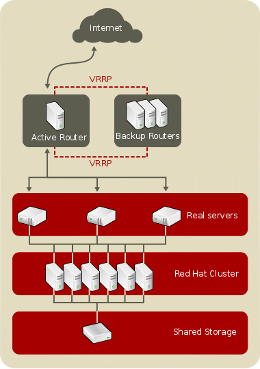
Figure 2.2, “A Three-Tier Load Balancer Configuration” shows a typical three-tier Keepalived Load Balancer topology. In this example, the active LVS router routes the requests from the Internet to the pool of real servers. Each of the real servers then accesses a shared data source over the network.
Figure 2.2. A Three-Tier Load Balancer Configuration
This configuration is ideal for busy FTP servers, where accessible data is stored on a central, highly available server and accessed by each real server by means of an exported NFS directory or Samba share. This topology is also recommended for websites that access a central, highly available database for transactions. Additionally, using an active-active configuration with the Load Balancer, administrators can configure one high-availability cluster to serve both of these roles simultaneously.
The third tier in the above example does not have to use the Load Balancer, but failing to use a highly available solution would introduce a critical single point of failure.
