Red Hat AMQ 6
As of February 2025, Red Hat is no longer supporting Red Hat AMQ 6. If you are using AMQ 6, please upgrade: Migrating to AMQ 7.Questo contenuto non è disponibile nella lingua selezionata.
Chapter 6. Network Topologies
Abstract
The topology of your network describes the pattern created by the pathways through your network. Different topologies are appropriate for particular use cases.
Overview
Copia collegamentoCollegamento copiato negli appunti!
The following examples illustrate some of the common topologies encountered real-world networks:
Concentrator topology
Copia collegamentoCollegamento copiato negli appunti!
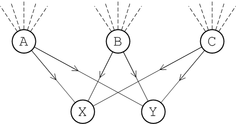
If you anticipate that your system will have a large number of incoming connections that would overwhelm a single broker, you can deploy a concentrator topology to deal with this scenario, as shown in Figure 6.1, “Concentrator Topology”.
Figure 6.1. Concentrator Topology
The idea of the concentrator topology is that you deploy brokers in two (or more) layers in order to funnel incoming connections into a smaller collection of services. The first layer consists of a relatively large number of brokers, with each broker servicing a large number of incoming connections (from producers
P1 to Pn). The next layer consists of a smaller number of brokers, where each broker in the first layer connects to all of the brokers in the second layer. With this topology, each broker in the second layer can receive messages from any of the producers.
Hub and spokes topology
Copia collegamentoCollegamento copiato negli appunti!
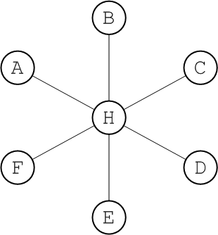
The hub and spokes, as shown in Figure 6.2, “Hub and Spoke Topology”, is a topology that is relatively easy to set up and maintain. The edges in this graph are all assumed to represent duplex network connectors.
Figure 6.2. Hub and Spoke Topology
This topology is relatively robust. The only critical element is the hub node, so you would need to focus your maintenance efforts on keeping the hub up and running. Routes are determinate and the diameter of the network is always 2, no matter how many nodes are added.
Tree topology
Copia collegamentoCollegamento copiato negli appunti!
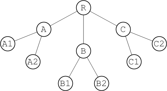
The tree, as shown in Figure 6.3, “Tree Topology”, is a topology that arises naturally when a physical network grows in an informal manner.
Figure 6.3. Tree Topology
For example, if the network under consideration is an ethernet LAN,
R could represent the hub in the basement of the IT department's building and A could represent a router in the ground floor of another building. If you want to extend the LAN to the first and second floor of building A, you are unlikely to run dedicated cables back to the IT hub for each of these floors. It is more likely that you will simply plug a second tier of routers, A1 and A2, into the existing router, A, on the ground floor. In this way, you effectively add another layer to the tree topology.
Mesh topology
Copia collegamentoCollegamento copiato negli appunti!
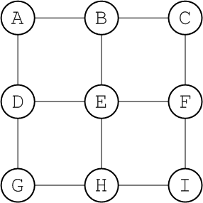
The mesh, as shown in Figure 6.4, “Mesh Topology”, is a topology that arises naturally in a geographic network, when you decide to link together neighbouring hubs.
Figure 6.4. Mesh Topology
The diameter of a mesh increases whenever you add a node to its periphery. You must, therefore, be careful to set the network TTL sufficiently high that your network can cope with expansion. Alternatively, you could set up some mechanism for the central management of broker configurations. This would enable you to increase the network TTL for all of the brokers simultaneously.
Complete graph
Copia collegamentoCollegamento copiato negli appunti!
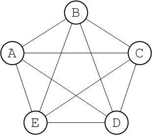
In graph theory, the complete graph on
n vertices is the graph with n vertices that has edges joining every pair of vertices. This graph is denoted by the symbol, Kn. For example, Figure 6.5, “The Complete Graph, K5” shows the graph, K5.
Figure 6.5. The Complete Graph, K5
Every complete graph has a diameter of 1. Potentially, a network that is a complete graph could be difficult to manage, because there are many connections between broker nodes. In practice, though, it is relatively easy to set up a broker network as a complete graph, if you define all of the network connectors to use a multicast discovery agent (see Section 8.1.3, “Multicast Discovery Agent”).
Note
In the complete graph topology, it is mandatory to set
networkTTL=1 in the network connector elements, in order for the broker network to function correctly.
