Este conteúdo não está disponível no idioma selecionado.
5.5. Adding and Deleting Members
The procedures to add or delete a cluster member vary depending on whether the cluster is a newly configured cluster or a cluster that is already configured and running.
To add a member to a new cluster, refer to Section 5.5.1, “Adding a Member to a New Cluster”.
To add or delete a cluster member in an existing cluster, refer to the following sections:
5.5.1. Adding a Member to a New Cluster
Copiar o linkLink copiado para a área de transferência!
To add a member to a new cluster, follow these steps:
- At
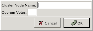
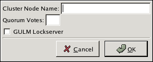
system-config-cluster, in the Cluster Configuration Tool tab, click . - At the bottom of the right frame (labeled ), click the button. Clicking that button causes a Node Properties dialog box to be displayed. For a DLM cluster, the Node Properties dialog box presents text boxes for and (refer to Figure 5.5, “Adding a Member to a New DLM Cluster”). For a GULM cluster, the Node Properties dialog box presents text boxes for and , and presents a checkbox for (refer to Figure 5.6, “Adding a Member to a New GULM Cluster”)
Important
The number of nodes that can be configured as GULM lock servers is limited to either one, three, or five.Figure 5.5. Adding a Member to a New DLM Cluster
Figure 5.6. Adding a Member to a New GULM Cluster
- At the text box, specify a node name. The entry can be a name or an IP address of the node on the cluster subnet.
Note
Each node must be on the same subnet as the node from which you are running the Cluster Configuration Tool and must be defined either in DNS or in the/etc/hostsfile of each cluster node.Note
The node on which you are running the Cluster Configuration Tool must be explicitly added as a cluster member; the node is not automatically added to the cluster configuration as a result of running the Cluster Configuration Tool. - Optionally, at the text box, you can specify a value; however in most configurations you can leave it blank. Leaving the text box blank causes the quorum votes value for that node to be set to the default value of
1. - Click .
- Configure fencing for the node:
- Click the node that you added in the previous step.
- At the bottom of the right frame (below ), click . Clicking causes the Fence Configuration dialog box to be displayed.
- At the Fence Configuration dialog box, bottom of the right frame (below ), click . Clicking causes a fence-level element (for example, , , and so on) to be displayed below the node in the left frame of the Fence Configuration dialog box.
- Click the fence-level element.
- At the bottom of the right frame (below ), click . Clicking causes the Fence Properties dialog box to be displayed.
- At the Fence Properties dialog box, click the drop-down box and select the fence device for this node. Also, provide additional information required (for example, and for an APC Power Device).
- At the Fence Properties dialog box, click . Clicking causes a fence device element to be displayed below the fence-level element.
- To create additional fence devices at this fence level, return to step 6d. Otherwise, proceed to the next step.
- To create additional fence levels, return to step 6c. Otherwise, proceed to the next step.
- If you have configured all the fence levels and fence devices for this node, click .
- Choose => to save the changes to the cluster configuration.
To continue configuring a new cluster, proceed to Section 5.6, “Configuring a Failover Domain”.

