此内容没有您所选择的语言版本。
Chapter 1. Load Balancer Add-On Overview
Note
As of Red Hat Enterprise Linux 6.6, Red Hat provides support for HAProxy and keepalived in addition to the Piranha load balancing software. For information on configuring a Red Hat Enterprise Linux system with HAProxy and keepalived, see the Load Balancer Administration documentation for Red Hat Enterprise Linux 7.
The Load Balancer Add-On is a set of integrated software components that provide Linux Virtual Servers (LVS) for balancing IP load across a set of real servers. The Load Balancer Add-On runs on an active LVS router as well as a backup LVS router. The active LVS router serves two roles:
- To balance the load across the real servers.
- To check the integrity of the services on each real server.
The backup LVS router monitors the active LVS router and takes over from it in case the active LVS router fails.
This chapter provides an overview of The Load Balancer Add-On components and functions, and consists of the following sections:
1.1. A Basic Load Balancer Add-On Configuration
复制链接链接已复制到粘贴板!
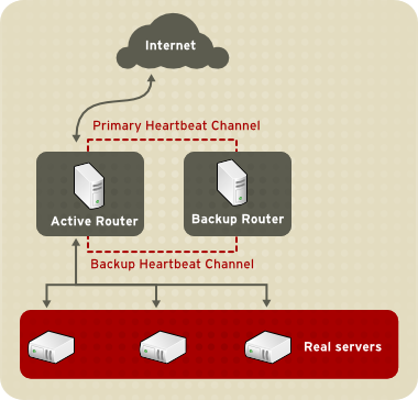
Figure 1.1, “A Basic Load Balancer Add-On Configuration” shows a simple Load Balancer Add-On configuration consisting of two layers. On the first layer is one active and one backup LVS router. Each LVS router has two network interfaces, one interface on the Internet and one on the private network, enabling them to regulate traffic between the two networks. For this example the active router is using Network Address Translation or NAT to direct traffic from the Internet to a variable number of real servers on the second layer, which in turn provide the necessary services. Therefore, the real servers in this example are connected to a dedicated private network segment and pass all public traffic back and forth through the active LVS router. To the outside world, the servers appears as one entity.
Figure 1.1. A Basic Load Balancer Add-On Configuration
Service requests arriving at the LVS router are addressed to a virtual IP address, or VIP. This is a publicly-routable address the administrator of the site associates with a fully-qualified domain name, such as www.example.com, and is assigned to one or more virtual servers. A virtual server is a service configured to listen on a specific virtual IP. Refer to Section 4.6, “VIRTUAL SERVERS” for more information on configuring a virtual server using the Piranha Configuration Tool. A VIP address migrates from one LVS router to the other during a failover, thus maintaining a presence at that IP address (also known as floating IP addresses).
VIP addresses may be aliased to the same device which connects the LVS router to the Internet. For instance, if eth0 is connected to the Internet, than multiple virtual servers can be aliased to
eth0:1. Alternatively, each virtual server can be associated with a separate device per service. For example, HTTP traffic can be handled on eth0:1, and FTP traffic can be handled on eth0:2.
Only one LVS router is active at a time. The role of the active router is to redirect service requests from virtual IP addresses to the real servers. The redirection is based on one of eight supported load-balancing algorithms described further in Section 1.3, “Load Balancer Add-On Scheduling Overview”.
The active router also dynamically monitors the overall health of the specific services on the real servers through simple send/expect scripts. To aid in detecting the health of services that require dynamic data, such as HTTPS or SSL, the administrator can also call external executables. If a service on a real server malfunctions, the active router stops sending jobs to that server until it returns to normal operation.
The backup router performs the role of a standby system. Periodically, the LVS router exchanges heartbeat messages through the primary external public interface and, in a failover situation, the private interface. Should the backup node fail to receive a heartbeat message within an expected interval, it initiates a failover and assumes the role of the active router. During failover, the backup router takes over the VIP addresses serviced by the failed router using a technique known as ARP spoofing — where the backup LVS router announces itself as the destination for IP packets addressed to the failed node. When the failed node returns to active service, the backup node assumes its hot-backup role again.
The simple, two-layered configuration used in Figure 1.1, “A Basic Load Balancer Add-On Configuration” is best for serving data which does not change very frequently — such as static webpages — because the individual real servers do not automatically sync data between each node.
Since there is no built-in component in Load Balancer Add-On to share the same data between the real servers, the administrator has two basic options:
- Synchronize the data across the real server pool
- Add a third layer to the topology for shared data access
The first option is preferred for servers that do not allow large numbers of users to upload or change data on the real servers. If the configuration allows large numbers of users to modify data, such as an e-commerce website, adding a third layer is preferable.
1.1.1.1. Configuring Real Servers to Synchronize Data
复制链接链接已复制到粘贴板!
There are many ways an administrator can choose to synchronize data across the pool of real servers. For instance, shell scripts can be employed so that if a Web engineer updates a page, the page is posted to all of the servers simultaneously. Also, the system administrator can use programs such as
rsync to replicate changed data across all nodes at a set interval.
However, this type of data synchronization does not optimally function if the configuration is overloaded with users constantly uploading files or issuing database transactions. For a configuration with a high load, a three-tier topology is the ideal solution.
