此内容没有您所选择的语言版本。
Chapter 9. Using Composable Networks
With composable networks, you are no longer constrained by the pre-defined network segments (Internal, Storage, Storage Management, Tenant, External, Control Plane), and instead you can now create your own networks and assign them to any role: default or custom. For example, if you have a network dedicated to NFS traffic, you can now present it to multiple different roles.
Director supports the creation of custom networks during the deployment and update phases. These additional networks can be used for ironic bare metal nodes, system management, or to create separate networks for different roles. They can also be used to create multiple sets of networks for split deployments, where traffic is routed between networks.
A single data file (network_data.yaml) manages the list of networks that will be deployed; the role definition process then assigns the networks to the required roles through network isolation (see Chapter 8, Isolating Networks for more information).
9.1. Defining a Composable Network
To create composable networks, edit a local copy of the /usr/share/openstack-tripleo-heat-templates/network_data.yaml Heat template. For example:
- name: StorageBackup
  vip: true
  name_lower: storage_backup
  ip_subnet: '172.21.1.0/24'
  allocation_pools: [{'start': '171.21.1.4', 'end': '172.21.1.250'}]
  gateway_ip: '172.21.1.1'
  ipv6_subnet: 'fd00:fd00:fd00:7000::/64'
  ipv6_allocation_pools: [{'start': 'fd00:fd00:fd00:7000::10', 'end': 'fd00:fd00:fd00:7000:ffff:ffff:ffff:fffe'}]
gateway_ipv6: 'fd00:fd00:fd00:7000::1'-
name - is the only mandatory value, however you can also use
name_lowerto normalize names for readability. For example, changingInternalApitointernal_api. - vip:true will create a virtual IP address (VIP) on the new network, with the remaining parameters setting the defaults for the new network.
- ip_subnet and allocation_pools will set the default IPv4 subnet and IP range for the network.
- ipv6_subnet and ipv6_allocation_pools will set the default IPv6 subnets for the network.
You can override these defaults using an environment file (usually named network-environment.yaml). The sample network-environment.yaml file can be created after modifying the network_data.yaml file by running this command from the root of the director’s core Heat templates you are using (local copy of /usr/share/openstack-tripleo-heat-templates/):
[stack@undercloud ~/templates] $ ./tools/process-templates.py
When using composable networks, the parameter definition for the network IP address must be added to the NIC configuration template used for each role, even if the network is not used on the role. See the directories in /usr/share/openstack-tripleo-heat-templates/network/config for examples of these NIC configurations. For instance, if a StorageBackup network is added to only the Ceph nodes, the following would need to be added to the resource definitions in the NIC configuration templates for all roles:
  StorageBackupIpSubnet:
    default: ''
    description: IP address/subnet on the external network
    type: string
You may also create resource definitions for VLAN IDs and/or gateway IP, if needed:
  StorageBackupNetworkVlanID: # Override this via parameter_defaults in network_environment.yaml
    default: 60
    description: Vlan ID for the management network traffic.
    type: number
  StorageBackupDefaultRoute: # Override this via parameter_defaults in network_environment.yaml
  description: The default route of the storage backup network.
  type: string
The IpSubnet parameter for the custom network appears in the parameter definitions for each role. However, since the Ceph role is the only role that makes use of the StorageBackup network in our example, only the NIC configuration template for the Ceph role would make use of the StorageBackup parameters in the network_config section of the template.
            $network_config:
            network_config:
            - type: interface
              name: nic1
              use_dhcp: false
              addresses:
              - ip_netmask:
                  Get_param: StorageBackupIpSubnet
9.1.2. Assign Composable Networks to Services
If vip: true is specified in the custom network definition, then it is possible to assign services to the network using the ServiceNetMap parameters. The custom network chosen for the service must exist on the role hosting the service. You can override the default networks by overriding the ServiceNetMap that is defined in /usr/share/openstack-tripleo-heat-templates/network/service_net_map.j2.yaml in your network_environment.yaml (or in a different environment file):
parameter_defaults:
  ServiceNetMap:
  NeutronTenantNetwork: tenant
  CeilometerApiNetwork: internal_api
  AodhApiNetwork: internal_api
  GnocchiApiNetwork: internal_api
  MongoDbNetwork: internal_api
  CinderApiNetwork: internal_api
  CinderIscsiNetwork: storage
  GlanceApiNetwork: storage
  GlanceRegistryNetwork: internal_api
  KeystoneAdminApiNetwork: ctlplane # Admin connection for Undercloud
  KeystonePublicApiNetwork: internal_api
  NeutronApiNetwork: internal_api
  HeatApiNetwork: internal_api
  NovaApiNetwork: internal_api
  NovaMetadataNetwork: internal_api
  NovaVncProxyNetwork: internal_api
  SwiftMgmtNetwork: storage_backup # Changed from storage_mgmt
  SwiftProxyNetwork: storage
  SaharaApiNetwork: internal_api
  HorizonNetwork: internal_api
  MemcachedNetwork: internal_api
  RabbitMqNetwork: internal_api
  RedisNetwork: internal_api
  MysqlNetwork: internal_api
  CephClusterNetwork: storage_backup # Changed from storage_mgmt
  CephPublicNetwork: storage
  ControllerHostnameResolveNetwork: internal_api
  ComputeHostnameResolveNetwork: internal_api
  BlockStorageHostnameResolveNetwork: internal_api
  ObjectStorageHostnameResolveNetwork: internal_api
  CephStorageHostnameResolveNetwork: storage
9.1.3. Define the Routed Networks
When using composable networks to deploy routed networks, you define routes and router gateways for use in the network configuration. You can create network routes and supernet routes to define which interface to use when routing traffic between subnets. For example, in a deployment where traffic is routed between the Compute and Controller roles, you may want to define supernets for sets of isolated networks. For instance, 172.17.0.0/16 is a supernet that contains all networks beginning with 172.17, so the Internal API network used on the controllers might use 172.17.1.0/24 and the Internal API network used on the Compute nodes might use 172.17.2.0/24. On both roles, you would define a route to the 172.17.0.0/16 supernet through the router gateway that is specific to the network used on the role.
The available parameters in network-environment.yaml:
  InternalApiSupernet:
    default: '172.17.0.0/16'
    description: Supernet that contains Internal API subnets for all roles.
    type: string
  InternalApiGateway:
    default: '172.17.1.1'
    description: Router gateway on Internal API network
    type: string
  InternalApi2Gateway:
    default: '172.17.2.1'
    description: Router gateway on Internal API 2 network
    Type: string
These parameters can be used in the NIC configuration templates for the roles.
The controller uses the parameters for the InternalApi network in controller.yaml:
            - type: interface
              name: nic3
              use_dhcp: false
              addresses:
              - ip_netmask:
                  get_param: InternalApiIpSubnet
              - routes:
                  ip_netmask:
                    get_param: InternalApiSupernet
                  next_hop:
                    Get_param: InternalApiGateway
The compute role uses the parameters for the InternalApi2 network in compute.yaml:
            - type: interface
              name: nic3
              use_dhcp: false
              addresses:
              - ip_netmask:
                  get_param: InternalApi2IpSubnet
              - routes:
                  ip_netmask:
                    get_param: InternalApiSupernet
                  next_hop:
Get_param: InternalApi2GatewayIf specific network routes are not applied on isolated networks, all traffic to non-local networks use the default gateway. This is generally undesirable from both a security and performance standpoint since it mixes different kinds of traffic and puts all outbound traffic on the same interface. In addition, if the routing is asymmetric (traffic is sent through a different interface than received), it might cause unreachable services. Using a route to the supernet on both the client and server directs traffic to use the correct interface on both sides.
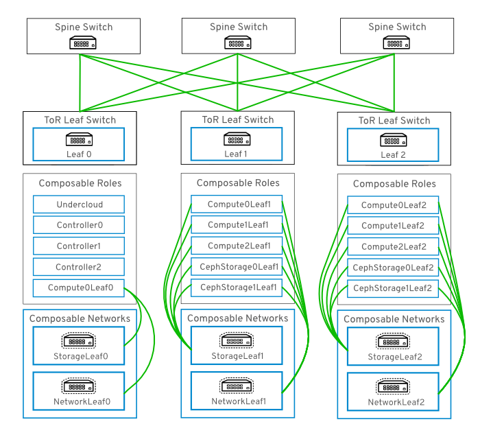
9.2. Networking with Routed Spine-Leaf
Composable networks allow you to adapt your OpenStack Networking deployment to the popular routed spine-leaf data center topology. In a practical application of routed spine-leaf, a leaf is represented as a composable Compute or Storage role usually in a datacenter rack, as shown in Figure 9.1, “Routed spine-leaf example”. The leaf 0 rack has an undercloud node, controllers, and compute nodes. The composable networks are presented to the nodes, which have been assigned to composable roles. In this diagram, the StorageLeaf networks are presented to the Ceph storage and Compute nodes; the NetworkLeaf represents an example of any network you may want to compose.
Figure 9.1. Routed spine-leaf example
9.3. Hardware Provisioning with Routed Spine-Leaf
This section describes an example hardware provisioning use case and explains how to deploy an evaluation environment to demonstrate the functionality of routed spine-leaf with composable networks. The resulting deployment has multiple sets of networks with routing available.
To use a provisioning network in a routed spine-leaf network, there are two options available: a VXLAN tunnel configured in the switch fabric, or an extended VLAN trunked to each ToR switch:
In a future release, it is expected that DHCP relays can be used to make DHCPOFFER broadcasts traverse across the routed layer 3 domains.
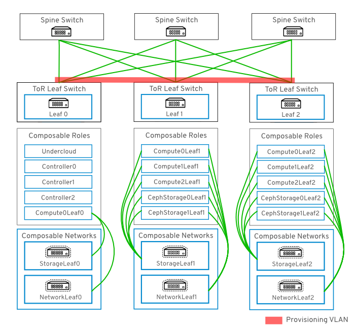
9.3.1. Example VLAN Provisioning Network
In this example, new overcloud nodes are deployed through the provisioning network. The provisioning network cannot be composed, and there cannot be more than one. Instead, a VLAN tunnel is used to span across the layer 3 topology (see Figure 9.2, “VLAN provisioning network topology”). This allows DHCPOFFER broadcasts to be sent to any leaf. This tunnel is established by trunking a VLAN between the Top-of-Rack (ToR) leaf switches. In this diagram, the StorageLeaf networks are presented to the Ceph storage and Compute nodes; the NetworkLeaf represents an example of any network you may want to compose.
Figure 9.2. VLAN provisioning network topology
9.3.2. Example VXLAN Provisioning Network
In this example, new overcloud nodes are deployed through the provisioning network. The provisioning network cannot be composed, and there cannot be more than one. Instead, VXLAN tunnel is used to span across the layer 3 topology (see Figure 9.3, “VXLAN provisioning network topology”). This allows DHCPOFFER broadcasts to be sent to any leaf. This tunnel is established using VXLAN endpoints configured on the Top-of-Rack (ToR) leaf switches.
Figure 9.3. VXLAN provisioning network topology

9.3.3. Network Topology for Provisioning
The routed spine-leaf bare metal environment has one or more layer 3 capable switches, which route traffic between the isolated VLANs in the separate layer 2 broadcast domains.
The intention of this design is to isolate the traffic according to function. For example, if the controller nodes host an API on the Internal API network, when a compute node accesses the API it should use its own version of the Internal API network. For this routing to work, you need routes that force traffic destined for the Internal API network to use the required interface. This can be configured using supernet routes. For example, if you use 172.18.0.0/24 as the Internal API network for the controller nodes, you can use 172.18.1.0/24 for the second Internal API network, and 172.18.2.0/24 for the third, and so on. As a result, you can have a route pointing to the larger 172.18.0.0/16 supernet that uses the gateway IP on the local Internal API network for each role in each layer 2 domain.
The following networks could be used in an environment that was deployed using director:
| Network | Roles attached | Interface | Bridge | Subnet |
|---|---|---|---|---|
| Provisioning | All | UC - nic2 and Other - nic1 | UC: br-ctlplane | |
| External | Controller | nic7, OC: nic6 | br-ex | 192.168.24.0/24 |
| Storage | Controller | nic3, OC: nic2 | 172.16.0.0/24 | |
| Storage Mgmt | Controller | nic4, OC: nic3 | 172.17.0.0/24 | |
| Internal API | Controller | nic5, OC: nic4 | 172.18.0.0/24 | |
| Tenant | Controller | nic6, OC: nic5 | 172.19.0.0/24 | |
| Storage1 | Compute1, Ceph1 | nic8, OC: nic7 | 172.16.1.0/24 | |
| Storage Mgmt1 | Ceph1 | nic9, OC: nic8 | 172.17.1.0/24 | |
| Internal API1 | Compute1 | nic10, OC: nic9 | 172.18.1.0/24 | |
| Tenant1 | Compute1 | nic11, OC: nic10 | 172.19.1.0/24 | |
| Storage2 | Compute2, Ceph2 | nic12, OC: nic11 | 172.16.2.0/24 | |
| Storage Mgmt2 | Ceph2 | nic13, OC: nic12 | 172.17.2.0/24 | |
| Internal API2 | Compute2 | nic14, OC: nic13 | 172.18.2.0/24 | |
| Tenant2 | Compute2 | nic15, OC:nic14 | 172.19.2.0/24 |
The undercloud must also be attached to an uplink for external/Internet connectivity. Typically, the undercloud would be the only node attached to the uplink network. This is likely to be an infrastructure VLAN, separate from the OpenStack deployment.
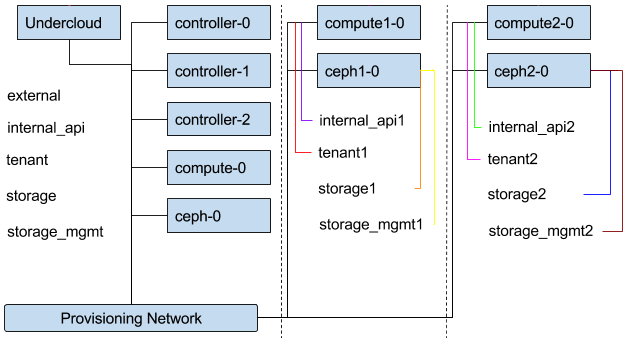
9.3.4. Topology Diagram
Figure 9.4. Composable Network Topology
9.3.5. Assign IP Addresses to the Custom Roles
The roles require routes for each of the isolated networks. Each role has its own NIC configs and you have to customize the TCP/IP settings to support the custom networks. You can also parameterize or hard-code the gateway IP addresses and routes into the role NIC configs.
For example, using the existing NIC configs as a basic template, you must add the network-specific parameters to all NIC configs:
  StorageMgmtIpSubnet:
  default: ''
  description: IP address/subnet on the storage_mgmt network
  type: string
  StorageMgmt2IpSubnet:
    default: ''
  description: IP address/subnet on the storage_mgmt2 network
  type: string
  TenantIpSubnet:
  default: ''
  description: IP address/subnet on the tenant network
  type: string
  TenantIp2Subnet:
  default: ''
  description: IP address/subnet on the tenant2 network
  type: string
Perform this for each of the custom networks, for each role used in the deployment.
9.3.6. Assign Routes for the Roles
Each isolated network should have a supernet route applied. Using the suggestion above of 172.18.0.0/16 as the supernet route, you would apply the same route to each interface, but using the local gateway.
network-environment.yaml:parameter_defaults: InternalApiSupernet: 172.18.0.0/16 InternalApiInterfaceDefaultRoute: 172.18.0.1 InternalApi1InterfaceDefaultRoute: 172.18.1.1 InternalApi2InterfaceDefaultRoute: 172.18.2.1 InternalApi3InterfaceDefaultRoute: 172.18.3.1
Each role requires routes on each isolated network, pointing to the other subnets used for the same function. So when a Compute1 node contacts a controller on the InternalApi VIP, the traffic should target the InternalApi1 interface through the InternalApi1 gateway. As a result, the return traffic from the controller to the InternalApi1 network should go through the InternalApi network gateway.
Controller configuration:
            - type: interface
              name: nic4
              use_dhcp: false
              addresses:
              - ip_netmask:
                      get_param: InternalApiIpSubnet
                 routes:
                   - ip_netmask:
                       get_param: InternalApiSupernet
                     next_hop:
                       get_param: InternalApiDefaultRoute
Compute1 configuration:
            - type: interface
              name: nic4
              use_dhcp: false
              addresses:
              - ip_netmask:
                      get_param: InternalApi1IpSubnet
                 routes:
                   - ip_netmask:
                       get_param: InternalApiSupernet
                     next_hop:
                       get_param: InternalApi1DefaultRoute
The supernet routes apply to all isolated networks on each role to avoid sending traffic through the default gateway, which by default is the Control Plane network on non-controllers, and the External network on the controllers.
You need to configure these routes on the isolated networks because Red Hat Enterprise Linux by default implements strict reverse path filtering on inbound traffic. If an API is listening on the Internal API interface and a request comes in to that API, it only accepts the request if the return path route is on the Internal API interface. If the server is listening on the Internal API network but the return path to the client is through the Control Plane, then the server drops the requests due to the reverse path filter.
For example, this diagram shows an attempt to route traffic through the control plane, which will not succeed. The return route from the router to the controller node does not match the interface where the VIP is listening, so the packet is dropped. 192.168.24.0/24 is directly connected to the controller, so it is considered local to the Control Plane network.
Figure 9.5. Routed traffic through Control Plane
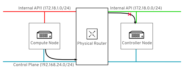
For comparison, this diagram shows routing running through the Internal API networks:
Figure 9.6. Routed traffic through Internal API
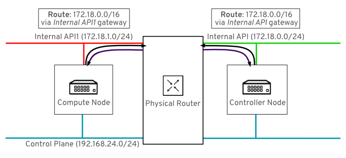
In this diagram, the return route to 172.18.1.0 matches the interface where the virtual IP address (VIP) is listening. As a result, packets are not dropped and the API connectivity works as expected.
The following ExtraConfig settings address the issue described above. Note that the InternalApi1 value is ultimately represented by the internal_api1 value and is case-sensitive.
parameter_defaults:
  Compute1ExtraConfig:
     nova::vncproxy::host: "%{hiera('internal_api1')}"
     neutron::agents::ml2::ovs::local_ip: "%{hiera('tenant1')}"
  Compute2ExtraConfig:
     nova::vncproxy::host: "%{hiera('internal_api2')}"
     neutron::agents::ml2::ovs::local_ip: "%{hiera('tenant2')}"
  Compute3ExtraConfig:
     nova::vncproxy::host: "%{hiera('internal_api3')}"
     neutron::agents::ml2::ovs::local_ip: "%{hiera('tenant3')}"
  CephAnsibleExtraConfig:
    public_network: '172.120.3.0/24,172.117.3.0/24,172.118.3.0/24,172.119.3.0/24'
cluster_network: '172.120.4.0/24,172.117.4.0/24,172.118.4.0/24,172.119.4.0/24'-
CephAnsibleExtraConfig- Thepublic_networksetting lists all the storage network leaves. Thecluster_networkentries lists the storage management networks (one per leaf).
9.3.7. Custom NIC definitions
The following custom definitions were applied in the nic-config template for nodes. Change the following example to suit your deployment:
Review the
network_data.yamlvalues. They should be similar to the following example:[stack@undercloud-0 ~]$ cat /home/stack/network_data.yaml - name: External vip: true name_lower: external ip_subnet: '10.0.0.0/24' allocation_pools: [{'start': '10.0.0.4', 'end': '10.0.0.250'}] gateway_ip: '10.0.0.1' ipv6_subnet: '2001:db8:fd00:1000::/64' ipv6_allocation_pools: [{'start': '2001:db8:fd00:1000::10', 'end': '2001:db8:fd00:1000:ffff:ffff:ffff:fffe'}] gateway_ipv6: '2001:db8:fd00:1000::1' - name: InternalApi name_lower: internal_api vip: true ip_subnet: '172.16.2.0/24' allocation_pools: [{'start': '172.16.2.4', 'end': '172.16.2.250'}] ipv6_subnet: 'fd00:fd00:fd00:2000::/64' ipv6_allocation_pools: [{'start': 'fd00:fd00:fd00:2000::10', 'end': 'fd00:fd00:fd00:2000:ffff:ffff:ffff:fffe'}] - name: Storage vip: true name_lower: storage ip_subnet: '172.16.1.0/24' allocation_pools: [{'start': '172.16.1.4', 'end': '172.16.1.250'}] ipv6_subnet: 'fd00:fd00:fd00:3000::/64' ipv6_allocation_pools: [{'start': 'fd00:fd00:fd00:3000::10', 'end': 'fd00:fd00:fd00:3000:ffff:ffff:ffff:fffe'}] - name: StorageMgmt name_lower: storage_mgmt vip: true ip_subnet: '172.16.3.0/24' allocation_pools: [{'start': '172.16.3.4', 'end': '172.16.3.250'}] ipv6_subnet: 'fd00:fd00:fd00:4000::/64' ipv6_allocation_pools: [{'start': 'fd00:fd00:fd00:4000::10', 'end': 'fd00:fd00:fd00:4000:ffff:ffff:ffff:fffe'}] - name: Tenant vip: false # Tenant network does not use VIPs name_lower: tenant ip_subnet: '172.16.0.0/24' allocation_pools: [{'start': '172.16.0.4', 'end': '172.16.0.250'}] ipv6_subnet: 'fd00:fd00:fd00:5000::/64' ipv6_allocation_pools: [{'start': 'fd00:fd00:fd00:5000::10', 'end': 'fd00:fd00:fd00:5000:ffff:ffff:ffff:fffe'}] - name: Management # Management network is enabled by default for backwards-compatibility, but # is not included in any roles by default. Add to role definitions to use. enabled: true vip: false # Management network does not use VIPs name_lower: management ip_subnet: '10.0.1.0/24' allocation_pools: [{'start': '10.0.1.4', 'end': '10.0.1.250'}] ipv6_subnet: 'fd00:fd00:fd00:6000::/64' ipv6_allocation_pools: [{'start': 'fd00:fd00:fd00:6000::10', 'end': 'fd00:fd00:fd00:6000:ffff:ffff:ffff:fffe'}] - name: Tenant1 vip: false # Tenant network does not use VIPs name_lower: tenant1 ip_subnet: '172.16.11.0/24' allocation_pools: [{'start': '172.16.11.4', 'end': '172.16.11.250'}] ipv6_subnet: 'fd00:fd00:fd00:5001::/64' ipv6_allocation_pools: [{'start': 'fd00:fd00:fd00:5001::10', 'end': 'fd00:fd00:fd00:5001:ffff:ffff:ffff:fffe'}] - name: Tenant2 vip: false # Tenant network does not use VIPs name_lower: tenant2 ip_subnet: '172.16.12.0/24' allocation_pools: [{'start': '172.16.12.4', 'end': '172.16.12.250'}] ipv6_subnet: 'fd00:fd00:fd00:5002::/64' ipv6_allocation_pools: [{'start': 'fd00:fd00:fd00:5002::10', 'end': 'fd00:fd00:fd00:5002:ffff:ffff:ffff:fffe'}] - name: Tenant3 vip: false # Tenant network does not use VIPs name_lower: tenant3 ip_subnet: '172.16.13.0/24' allocation_pools: [{'start': '172.16.13.4', 'end': '172.16.13.250'}] ipv6_subnet: 'fd00:fd00:fd00:5003::/64' ipv6_allocation_pools: [{'start': 'fd00:fd00:fd00:5003::10', 'end': 'fd00:fd00:fd00:5003:ffff:ffff:ffff:fffe'}] - name: StorageMgmt1 name_lower: storage_mgmt1 vip: true ip_subnet: '172.16.21.0/24' allocation_pools: [{'start': '172.16.21.4', 'end': '172.16.21.250'}] ipv6_subnet: 'fd00:fd00:fd00:4001::/64' ipv6_allocation_pools: [{'start': 'fd00:fd00:fd00:4001::10', 'end': 'fd00:fd00:fd00:4001:ffff:ffff:ffff:fffe'}] - name: StorageMgmt2 name_lower: storage_mgmt2 vip: true ip_subnet: '172.16.22.0/24' allocation_pools: [{'start': '172.16.22.4', 'end': '172.16.22.250'}] ipv6_subnet: 'fd00:fd00:fd00:4002::/64' ipv6_allocation_pools: [{'start': 'fd00:fd00:fd00:4002::10', 'end': 'fd00:fd00:fd00:4002:ffff:ffff:ffff:fffe'}] - name: StorageMgmt3 name_lower: storage_mgmt3 vip: true ip_subnet: '172.16.23.0/24' allocation_pools: [{'start': '172.16.23.4', 'end': '172.16.23.250'}] ipv6_subnet: 'fd00:fd00:fd00:4003::/64' ipv6_allocation_pools: [{'start': 'fd00:fd00:fd00:4003::10', 'end': 'fd00:fd00:fd00:4003:ffff:ffff:ffff:fffe'}] - name: Storage1 vip: true name_lower: storage1 ip_subnet: '172.16.31.0/24' allocation_pools: [{'start': '172.16.31.4', 'end': '172.16.31.250'}] ipv6_subnet: 'fd00:fd00:fd00:3001::/64' ipv6_allocation_pools: [{'start': 'fd00:fd00:fd00:3001::10', 'end': 'fd00:fd00:fd00:3001:ffff:ffff:ffff:fffe'}] - name: Storage2 vip: true name_lower: storage2 ip_subnet: '172.16.32.0/24' allocation_pools: [{'start': '172.16.32.4', 'end': '172.16.32.250'}] ipv6_subnet: 'fd00:fd00:fd00:3002::/64' ipv6_allocation_pools: [{'start': 'fd00:fd00:fd00:3002::10', 'end': 'fd00:fd00:fd00:3002:ffff:ffff:ffff:fffe'}] - name: Storage3 vip: true name_lower: storage3 ip_subnet: '172.16.33.0/24' allocation_pools: [{'start': '172.16.33.4', 'end': '172.16.33.250'}] ipv6_subnet: 'fd00:fd00:fd00:3003::/64' ipv6_allocation_pools: [{'start': 'fd00:fd00:fd00:3003::10', 'end': 'fd00:fd00:fd00:3003:ffff:ffff:ffff:fffe'}] - name: InternalApi1 name_lower: internal_api1 vip: true ip_subnet: '172.16.41.0/24' allocation_pools: [{'start': '172.16.41.4', 'end': '172.16.41.250'}] ipv6_subnet: 'fd00:fd00:fd00:2001::/64' ipv6_allocation_pools: [{'start': 'fd00:fd00:fd00:2001::10', 'end': 'fd00:fd00:fd00:2001:ffff:ffff:ffff:fffe'}] - name: InternalApi2 name_lower: internal_api2 vip: true ip_subnet: '172.16.42.0/24' allocation_pools: [{'start': '172.16.42.4', 'end': '172.16.42.250'}] ipv6_subnet: 'fd00:fd00:fd00:2002::/64' ipv6_allocation_pools: [{'start': 'fd00:fd00:fd00:2002::10', 'end': 'fd00:fd00:fd00:2002:ffff:ffff:ffff:fffe'}] - name: InternalApi3 name_lower: internal_api3 vip: true ip_subnet: '172.16.43.0/24' allocation_pools: [{'start': '172.16.43.4', 'end': '172.16.43.250'}] ipv6_subnet: 'fd00:fd00:fd00:2003::/64' ipv6_allocation_pools: [{'start': 'fd00:fd00:fd00:2003::10', 'end': 'fd00:fd00:fd00:2003:ffff:ffff:ffff:fffe'}]NoteThere is currently no validation performed for the network subnet and
allocation_poolsvalues. Be certain you have defined these consistently and there is no conflict with existing networks.Review the
/home/stack/roles_data.yamlvalues. They should be similar to the following example:#################################### # Role: Controller # #################################### - name: Controller description: | Controller role that has all the controler services loaded and handles Database, Messaging and Network functions. CountDefault: 1 tags: - primary - controller networks: - External - InternalApi - Storage - StorageMgmt - Tenant HostnameFormatDefault: '%stackname%-controller-%index%' ServicesDefault: - OS::TripleO::Services::AodhApi - OS::TripleO::Services::AodhEvaluator - OS::TripleO::Services::AodhListener - OS::TripleO::Services::AodhNotifier - OS::TripleO::Services::AuditD - OS::TripleO::Services::BarbicanApi - OS::TripleO::Services::CACerts - OS::TripleO::Services::CeilometerAgentCentral - OS::TripleO::Services::CeilometerAgentNotification - OS::TripleO::Services::CeilometerApi - OS::TripleO::Services::CeilometerCollector - OS::TripleO::Services::CeilometerExpirer - OS::TripleO::Services::CephExternal - OS::TripleO::Services::CephMds - OS::TripleO::Services::CephMon - OS::TripleO::Services::CephRbdMirror - OS::TripleO::Services::CephRgw - OS::TripleO::Services::CertmongerUser - OS::TripleO::Services::CinderApi - OS::TripleO::Services::CinderBackendDellPs - OS::TripleO::Services::CinderBackendDellSc - OS::TripleO::Services::CinderBackendDellEMCUnity - OS::TripleO::Services::CinderBackendDellEMCVMAXISCSI - OS::TripleO::Services::CinderBackendNetApp - OS::TripleO::Services::CinderBackendScaleIO - OS::TripleO::Services::CinderBackendVRTSHyperScale - OS::TripleO::Services::CinderBackup - OS::TripleO::Services::CinderHPELeftHandISCSI - OS::TripleO::Services::CinderScheduler - OS::TripleO::Services::CinderVolume - OS::TripleO::Services::Clustercheck - OS::TripleO::Services::Collectd - OS::TripleO::Services::Congress - OS::TripleO::Services::Docker - OS::TripleO::Services::Ec2Api - OS::TripleO::Services::Etcd - OS::TripleO::Services::ExternalSwiftProxy - OS::TripleO::Services::FluentdClient - OS::TripleO::Services::GlanceApi - OS::TripleO::Services::GnocchiApi - OS::TripleO::Services::GnocchiMetricd - OS::TripleO::Services::GnocchiStatsd - OS::TripleO::Services::HAproxy - OS::TripleO::Services::HeatApi - OS::TripleO::Services::HeatApiCfn - OS::TripleO::Services::HeatApiCloudwatch - OS::TripleO::Services::HeatEngine - OS::TripleO::Services::Horizon - OS::TripleO::Services::IronicApi - OS::TripleO::Services::IronicConductor - OS::TripleO::Services::Iscsid - OS::TripleO::Services::Keepalived - OS::TripleO::Services::Kernel - OS::TripleO::Services::Keystone - OS::TripleO::Services::ManilaApi - OS::TripleO::Services::ManilaBackendCephFs - OS::TripleO::Services::ManilaBackendGeneric - OS::TripleO::Services::ManilaBackendIsilon - OS::TripleO::Services::ManilaBackendNetapp - OS::TripleO::Services::ManilaBackendUnity - OS::TripleO::Services::ManilaBackendVNX - OS::TripleO::Services::ManilaBackendVMAX - OS::TripleO::Services::ManilaScheduler - OS::TripleO::Services::ManilaShare - OS::TripleO::Services::Memcached - OS::TripleO::Services::MongoDb - OS::TripleO::Services::MySQL - OS::TripleO::Services::MySQLClient - OS::TripleO::Services::NeutronApi - OS::TripleO::Services::NeutronBgpVpnApi - OS::TripleO::Services::NeutronCorePlugin - OS::TripleO::Services::NeutronDhcpAgent - OS::TripleO::Services::NeutronL2gwAgent - OS::TripleO::Services::NeutronL2gwApi - OS::TripleO::Services::NeutronL3Agent - OS::TripleO::Services::NeutronLbaasv2Agent - OS::TripleO::Services::NeutronLinuxbridgeAgent - OS::TripleO::Services::NeutronMetadataAgent - OS::TripleO::Services::NeutronML2FujitsuCfab - OS::TripleO::Services::NeutronML2FujitsuFossw - OS::TripleO::Services::NeutronOvsAgent - OS::TripleO::Services::NeutronVppAgent - OS::TripleO::Services::NovaApi - OS::TripleO::Services::NovaConductor - OS::TripleO::Services::NovaConsoleauth - OS::TripleO::Services::NovaIronic - OS::TripleO::Services::NovaMetadata - OS::TripleO::Services::NovaPlacement - OS::TripleO::Services::NovaScheduler - OS::TripleO::Services::NovaVncProxy - OS::TripleO::Services::Ntp - OS::TripleO::Services::ContainersLogrotateCrond - OS::TripleO::Services::OctaviaApi - OS::TripleO::Services::OctaviaHealthManager - OS::TripleO::Services::OctaviaHousekeeping - OS::TripleO::Services::OctaviaWorker - OS::TripleO::Services::OpenDaylightApi - OS::TripleO::Services::OpenDaylightOvs - OS::TripleO::Services::OVNDBs - OS::TripleO::Services::OVNController - OS::TripleO::Services::Pacemaker - OS::TripleO::Services::PankoApi - OS::TripleO::Services::RabbitMQ - OS::TripleO::Services::Redis - OS::TripleO::Services::SaharaApi - OS::TripleO::Services::SaharaEngine - OS::TripleO::Services::Securetty - OS::TripleO::Services::SensuClient - OS::TripleO::Services::Snmp - OS::TripleO::Services::Sshd - OS::TripleO::Services::SwiftProxy - OS::TripleO::Services::SwiftRingBuilder - OS::TripleO::Services::SwiftStorage - OS::TripleO::Services::Tacker - OS::TripleO::Services::Timezone - OS::TripleO::Services::TripleoFirewall - OS::TripleO::Services::TripleoPackages - OS::TripleO::Services::Tuned - OS::TripleO::Services::Vpp - OS::TripleO::Services::Zaqar #################################### # Role: Compute # #################################### - name: Compute1 description: | Basic Compute Node role CountDefault: 1 networks: - InternalApi1 - Tenant1 - Storage1 HostnameFormatDefault: '%stackname%-novacompute1-%index%' disable_upgrade_deployment: True ServicesDefault: - OS::TripleO::Services::AuditD - OS::TripleO::Services::CACerts - OS::TripleO::Services::CephClient - OS::TripleO::Services::CephExternal - OS::TripleO::Services::CertmongerUser - OS::TripleO::Services::Collectd - OS::TripleO::Services::ComputeCeilometerAgent - OS::TripleO::Services::ComputeNeutronCorePlugin - OS::TripleO::Services::ComputeNeutronL3Agent - OS::TripleO::Services::ComputeNeutronMetadataAgent - OS::TripleO::Services::ComputeNeutronOvsAgent - OS::TripleO::Services::Docker - OS::TripleO::Services::FluentdClient - OS::TripleO::Services::Iscsid - OS::TripleO::Services::Kernel - OS::TripleO::Services::MySQLClient - OS::TripleO::Services::NeutronLinuxbridgeAgent - OS::TripleO::Services::NeutronSriovAgent - OS::TripleO::Services::NeutronSriovHostConfig - OS::TripleO::Services::NeutronVppAgent - OS::TripleO::Services::NovaCompute - OS::TripleO::Services::NovaLibvirt - OS::TripleO::Services::NovaMigrationTarget - OS::TripleO::Services::Ntp - OS::TripleO::Services::ContainersLogrotateCrond - OS::TripleO::Services::OpenDaylightOvs - OS::TripleO::Services::Securetty - OS::TripleO::Services::SensuClient - OS::TripleO::Services::Snmp - OS::TripleO::Services::Sshd - OS::TripleO::Services::Timezone - OS::TripleO::Services::TripleoFirewall - OS::TripleO::Services::TripleoPackages - OS::TripleO::Services::Tuned - OS::TripleO::Services::Vpp - OS::TripleO::Services::OVNController #################################### # Role: CephStorage # #################################### - name: CephStorage1 description: | Ceph OSD Storage node role networks: - Storage1 - StorageMgmt1 ServicesDefault: - OS::TripleO::Services::AuditD - OS::TripleO::Services::CACerts - OS::TripleO::Services::CephOSD - OS::TripleO::Services::CertmongerUser - OS::TripleO::Services::Collectd - OS::TripleO::Services::Docker - OS::TripleO::Services::FluentdClient - OS::TripleO::Services::Kernel - OS::TripleO::Services::MySQLClient - OS::TripleO::Services::Ntp - OS::TripleO::Services::ContainersLogrotateCrond - OS::TripleO::Services::Securetty - OS::TripleO::Services::SensuClient - OS::TripleO::Services::Snmp - OS::TripleO::Services::Sshd - OS::TripleO::Services::Timezone - OS::TripleO::Services::TripleoFirewall - OS::TripleO::Services::TripleoPackages - OS::TripleO::Services::Tuned #################################### # Role: Compute # #################################### - name: Compute2 description: | Basic Compute Node role CountDefault: 1 networks: - InternalApi2 - Tenant2 - Storage2 HostnameFormatDefault: '%stackname%-novacompute2-%index%' disable_upgrade_deployment: True ServicesDefault: - OS::TripleO::Services::AuditD - OS::TripleO::Services::CACerts - OS::TripleO::Services::CephClient - OS::TripleO::Services::CephExternal - OS::TripleO::Services::CertmongerUser - OS::TripleO::Services::Collectd - OS::TripleO::Services::ComputeCeilometerAgent - OS::TripleO::Services::ComputeNeutronCorePlugin - OS::TripleO::Services::ComputeNeutronL3Agent - OS::TripleO::Services::ComputeNeutronMetadataAgent - OS::TripleO::Services::ComputeNeutronOvsAgent - OS::TripleO::Services::Docker - OS::TripleO::Services::FluentdClient - OS::TripleO::Services::Iscsid - OS::TripleO::Services::Kernel - OS::TripleO::Services::MySQLClient - OS::TripleO::Services::NeutronLinuxbridgeAgent - OS::TripleO::Services::NeutronSriovAgent - OS::TripleO::Services::NeutronSriovHostConfig - OS::TripleO::Services::NeutronVppAgent - OS::TripleO::Services::NovaCompute - OS::TripleO::Services::NovaLibvirt - OS::TripleO::Services::NovaMigrationTarget - OS::TripleO::Services::Ntp - OS::TripleO::Services::ContainersLogrotateCrond - OS::TripleO::Services::OpenDaylightOvs - OS::TripleO::Services::Securetty - OS::TripleO::Services::SensuClient - OS::TripleO::Services::Snmp - OS::TripleO::Services::Sshd - OS::TripleO::Services::Timezone - OS::TripleO::Services::TripleoFirewall - OS::TripleO::Services::TripleoPackages - OS::TripleO::Services::Tuned - OS::TripleO::Services::Vpp - OS::TripleO::Services::OVNController #################################### # Role: CephStorage # #################################### - name: CephStorage2 description: | Ceph OSD Storage node role networks: - Storage2 - StorageMgmt2 ServicesDefault: - OS::TripleO::Services::AuditD - OS::TripleO::Services::CACerts - OS::TripleO::Services::CephOSD - OS::TripleO::Services::CertmongerUser - OS::TripleO::Services::Collectd - OS::TripleO::Services::Docker - OS::TripleO::Services::FluentdClient - OS::TripleO::Services::Kernel - OS::TripleO::Services::MySQLClient - OS::TripleO::Services::Ntp - OS::TripleO::Services::ContainersLogrotateCrond - OS::TripleO::Services::Securetty - OS::TripleO::Services::SensuClient - OS::TripleO::Services::Snmp - OS::TripleO::Services::Sshd - OS::TripleO::Services::Timezone - OS::TripleO::Services::TripleoFirewall - OS::TripleO::Services::TripleoPackages - OS::TripleO::Services::Tuned #################################### # Role: Compute # #################################### - name: Compute3 description: | Basic Compute Node role CountDefault: 1 networks: - InternalApi3 - Tenant3 - Storage3 HostnameFormatDefault: '%stackname%-novacompute3-%index%' disable_upgrade_deployment: True ServicesDefault: - OS::TripleO::Services::AuditD - OS::TripleO::Services::CACerts - OS::TripleO::Services::CephClient - OS::TripleO::Services::CephExternal - OS::TripleO::Services::CertmongerUser - OS::TripleO::Services::Collectd - OS::TripleO::Services::ComputeCeilometerAgent - OS::TripleO::Services::ComputeNeutronCorePlugin - OS::TripleO::Services::ComputeNeutronL3Agent - OS::TripleO::Services::ComputeNeutronMetadataAgent - OS::TripleO::Services::ComputeNeutronOvsAgent - OS::TripleO::Services::Docker - OS::TripleO::Services::FluentdClient - OS::TripleO::Services::Iscsid - OS::TripleO::Services::Kernel - OS::TripleO::Services::MySQLClient - OS::TripleO::Services::NeutronLinuxbridgeAgent - OS::TripleO::Services::NeutronSriovAgent - OS::TripleO::Services::NeutronSriovHostConfig - OS::TripleO::Services::NeutronVppAgent - OS::TripleO::Services::NovaCompute - OS::TripleO::Services::NovaLibvirt - OS::TripleO::Services::NovaMigrationTarget - OS::TripleO::Services::Ntp - OS::TripleO::Services::ContainersLogrotateCrond - OS::TripleO::Services::OpenDaylightOvs - OS::TripleO::Services::Securetty - OS::TripleO::Services::SensuClient - OS::TripleO::Services::Snmp - OS::TripleO::Services::Sshd - OS::TripleO::Services::Timezone - OS::TripleO::Services::TripleoFirewall - OS::TripleO::Services::TripleoPackages - OS::TripleO::Services::Tuned - OS::TripleO::Services::Vpp - OS::TripleO::Services::OVNController #################################### # Role: CephStorage # #################################### - name: CephStorage3 description: | Ceph OSD Storage node role networks: - Storage3 - StorageMgmt3 ServicesDefault: - OS::TripleO::Services::AuditD - OS::TripleO::Services::CACerts - OS::TripleO::Services::CephOSD - OS::TripleO::Services::CertmongerUser - OS::TripleO::Services::Collectd - OS::TripleO::Services::Docker - OS::TripleO::Services::FluentdClient - OS::TripleO::Services::Kernel - OS::TripleO::Services::MySQLClient - OS::TripleO::Services::Ntp - OS::TripleO::Services::ContainersLogrotateCrond - OS::TripleO::Services::Securetty - OS::TripleO::Services::SensuClient - OS::TripleO::Services::Snmp - OS::TripleO::Services::Sshd - OS::TripleO::Services::Timezone - OS::TripleO::Services::TripleoFirewall - OS::TripleO::Services::TripleoPackages - OS::TripleO::Services::TunedReview the
nic-configtemplate for the Compute node:[stack@undercloud-0 ~]$ cat virt/network/three-nics-vlans/compute1.yaml heat_template_version: 2015-04-30 description: > Software Config to drive os-net-config to configure multiple interfaces for the compute role. parameters: InternalApi1InterfaceDefaultRoute: # Override this via parameter_defaults description: Default route for the specific network. type: string InternalApi2InterfaceDefaultRoute: # Override this via parameter_defaults description: Default route for the specific network. type: string InternalApi3InterfaceDefaultRoute: # Override this via parameter_defaults description: Default route for the specific network. type: string Tenant1InterfaceDefaultRoute: # Override this via parameter_defaults description: Default route for the specific network. type: string Tenant2InterfaceDefaultRoute: # Override this via parameter_defaults description: Default route for the specific network. type: string Tenant3InterfaceDefaultRoute: # Override this via parameter_defaults description: Default route for the specific network. type: string Storage1InterfaceDefaultRoute: # Override this via parameter_defaults description: Default route for the specific network. type: string Storage2InterfaceDefaultRoute: # Override this via parameter_defaults description: Default route for the specific network. type: string Storage3InterfaceDefaultRoute: # Override this via parameter_defaults description: Default route for the specific network. type: string InternalApi1NetworkVlanID: default: 21 description: Vlan ID for the internal_api network traffic. type: number InternalApi2NetworkVlanID: default: 22 description: Vlan ID for the internal_api network traffic. type: number InternalApi3NetworkVlanID: default: 23 description: Vlan ID for the internal_api network traffic. type: number Storage1NetworkVlanID: default: 31 description: Vlan ID for the storage network traffic. type: number Storage2NetworkVlanID: default: 32 description: Vlan ID for the storage network traffic. type: number Storage3NetworkVlanID: default: 33 description: Vlan ID for the storage network traffic. type: number StorageMgmt1NetworkVlanID: default: 41 description: Vlan ID for the storage mgmt network traffic. type: number StorageMgmt2NetworkVlanID: default: 42 description: Vlan ID for the storage mgmt network traffic. type: number StorageMgmt3NetworkVlanID: default: 43 description: Vlan ID for the storage mgmt network traffic. type: number Tenant1NetworkVlanID: default: 51 description: Vlan ID for the tenant network traffic. type: number Tenant2NetworkVlanID: default: 52 description: Vlan ID for the tenant network traffic. type: number Tenant3NetworkVlanID: default: 53 description: Vlan ID for the tenant network traffic. type: number ControlPlaneIp: default: '' description: IP address/subnet on the ctlplane network type: string ExternalIpSubnet: default: '' description: IP address/subnet on the external network type: string InternalApiIpSubnet: default: '' description: IP address/subnet on the internal API network type: string InternalApi1IpSubnet: default: '' description: IP address/subnet on the internal API network type: string InternalApi2IpSubnet: default: '' description: IP address/subnet on the internal API network type: string InternalApi3IpSubnet: default: '' description: IP address/subnet on the internal API network type: string Storage1IpSubnet: default: '' description: IP address/subnet on the storage network type: string Storage2IpSubnet: default: '' description: IP address/subnet on the storage network type: string Storage3IpSubnet: default: '' description: IP address/subnet on the storage network type: string StorageMgmt1IpSubnet: default: '' description: IP address/subnet on the storage mgmt network type: string StorageMgmt2IpSubnet: default: '' description: IP address/subnet on the storage mgmt network type: string StorageMgmt3IpSubnet: default: '' description: IP address/subnet on the storage mgmt network type: string Tenant1IpSubnet: default: '' description: IP address/subnet on the tenant network type: string Tenant2IpSubnet: default: '' description: IP address/subnet on the tenant network type: string Tenant3IpSubnet: default: '' description: IP address/subnet on the tenant network type: string StorageIpSubnet: default: '' description: IP address/subnet on the storage network type: string StorageMgmtIpSubnet: default: '' description: IP address/subnet on the storage mgmt network type: string TenantIpSubnet: default: '' description: IP address/subnet on the tenant network type: string ManagementIpSubnet: # Only populated when including environments/network-management.yaml default: '' description: IP address/subnet on the management network type: string InternalApiNetworkVlanID: default: 20 description: Vlan ID for the internal_api network traffic. type: number StorageNetworkVlanID: default: 30 description: Vlan ID for the storage network traffic. type: number TenantNetworkVlanID: default: 50 description: Vlan ID for the tenant network traffic. type: number ControlPlaneSubnetCidr: # Override this via parameter_defaults default: '24' description: The subnet CIDR of the control plane network. type: string ControlPlaneDefaultRoute: # Override this via parameter_defaults description: The subnet CIDR of the control plane network. type: string DnsServers: # Override this via parameter_defaults default: [] description: A list of DNS servers (2 max for some implementations) that will be added to resolv.conf. type: json EC2MetadataIp: # Override this via parameter_defaults description: The IP address of the EC2 metadata server. type: string resources: OsNetConfigImpl: type: OS::Heat::StructuredConfig properties: group: os-apply-config config: os_net_config: network_config: - type: interface name: nic1 use_dhcp: false dns_servers: {get_param: DnsServers} addresses: - ip_netmask: list_join: - '/' - - {get_param: ControlPlaneIp} - {get_param: ControlPlaneSubnetCidr} routes: - ip_netmask: 0.0.0.0/0 next_hop: {get_param: ControlPlaneDefaultRoute} # Optionally have this interface as default route default: true - ip_netmask: 169.254.169.254/32 next_hop: {get_param: EC2MetadataIp} - type: ovs_bridge name: br-isolated use_dhcp: false members: - type: interface name: nic2 # force the MAC address of the bridge to this interface primary: true - type: vlan vlan_id: {get_param: InternalApi1NetworkVlanID} addresses: - ip_netmask: {get_param: InternalApi1IpSubnet} routes: - ip_netmask: 172.120.1.0/24 next_hop: {get_param: InternalApi1InterfaceDefaultRoute} - ip_netmask: 172.118.1.0/24 next_hop: {get_param: InternalApi1InterfaceDefaultRoute} - ip_netmask: 172.119.1.0/24 next_hop: {get_param: InternalApi1InterfaceDefaultRoute} - type: vlan vlan_id: {get_param: Storage1NetworkVlanID} addresses: - ip_netmask: {get_param: Storage1IpSubnet} routes: - ip_netmask: 172.120.3.0/24 next_hop: {get_param: Storage1InterfaceDefaultRoute} - ip_netmask: 172.118.3.0/24 next_hop: {get_param: Storage1InterfaceDefaultRoute} - ip_netmask: 172.119.3.0/24 next_hop: {get_param: Storage1InterfaceDefaultRoute} - type: vlan vlan_id: {get_param: Tenant1NetworkVlanID} addresses: - ip_netmask: {get_param: Tenant1IpSubnet} routes: - ip_netmask: 172.120.2.0/24 next_hop: {get_param: Tenant1InterfaceDefaultRoute} - ip_netmask: 172.118.2.0/24 next_hop: {get_param: Tenant1InterfaceDefaultRoute} - ip_netmask: 172.119.2.0/24 next_hop: {get_param: Tenant1InterfaceDefaultRoute} - type: interface name: nic3 use_dhcp: false outputs: OS::stack_id: description: The OsNetConfigImpl resource. value: {get_resource: OsNetConfigImpl}Run the
openstack overcloud deploycommand to apply the changes. For example:openstack overcloud deploy --templates \ --libvirt-type kvm \ -n /home/stack/network_data.yaml \ -r /home/stack/roles_data.yaml \ -e /home/stack/templates/nodes_data.yaml \ -e /usr/share/openstack-tripleo-heat-templates/environments/ceph-ansible/ceph-ansible.yaml \ -e /usr/share/openstack-tripleo-heat-templates/environments/network-isolation.yaml \ -e /home/stack/virt/network/network-environment.yaml \ -e /usr/share/openstack-tripleo-heat-templates/environments/ssl/enable-tls.yaml \ -e /home/stack/virt/public_vip.yaml \ -e /usr/share/openstack-tripleo-heat-templates/environments/ssl/tls-endpoints-public-ip.yaml \ -e /home/stack/inject-trust-anchor-hiera.yaml \ -e /home/stack/rhos12.yaml