Dieser Inhalt ist in der von Ihnen ausgewählten Sprache nicht verfügbar.
System Design Guide
Designing a RHEL 8 system
Abstract
Providing feedback on Red Hat documentation
We appreciate your feedback on our documentation. Let us know how we can improve it.
Submitting feedback through Jira (account required)
- Log in to the Jira website.
- Click Create in the top navigation bar.
- Enter a descriptive title in the Summary field.
- Enter your suggestion for improvement in the Description field. Include links to the relevant parts of the documentation.
- Click Create at the bottom of the dialogue.
Part I. Design of installation
Chapter 1. System requirements and supported architectures
Red Hat Enterprise Linux 8 delivers a stable, secure, consistent foundation across hybrid cloud deployments with the tools needed to deliver workloads faster with less effort. You can deploy RHEL as a guest on supported hypervisors and Cloud provider environments as well as on physical infrastructure, so your applications can take advantage of innovations in the leading hardware architecture platforms.
Review the guidelines provided for system, hardware, security, memory, and RAID before installing.
If you want to use your system as a virtualization host, review the necessary hardware requirements for virtualization.
Red Hat Enterprise Linux supports the following architectures:
- AMD and Intel 64-bit architectures
- The 64-bit ARM architecture
- IBM Power Systems, Little Endian
- 64-bit IBM Z architectures
1.1. Supported installation targets
An installation target is a storage device that stores Red Hat Enterprise Linux and boots the system. Red Hat Enterprise Linux supports the following installation targets for IBMZ , IBM Power, AMD64, Intel 64, and 64-bit ARM systems:
- Storage connected by a standard internal interface, such as DASD, SCSI, SATA, or SAS
- BIOS/firmware RAID devices on the Intel64, AMD64 and arm64 architectures
-
NVDIMM devices in sector mode on the Intel64 and AMD64 architectures, supported by the
nd_pmemdriver. - Storage connected via Fibre Channel Host Bus Adapters, such as DASDs (IBM Z architecture only) and SCSI LUNs, including multipath devices. Some might require vendor-provided drivers.
- Xen block devices on Intel processors in Xen virtual machines.
- VirtIO block devices on Intel processors in KVM virtual machines.
Red Hat does not support installation to USB drives or SD memory cards. For information about support for third-party virtualization technologies, see the Red Hat Hardware Compatibility List.
1.2. System specifications
The Red Hat Enterprise Linux installation program automatically detects and installs your system’s hardware, so you should not have to supply any specific system information. However, for certain Red Hat Enterprise Linux installation scenarios, it is recommended that you record system specifications for future reference. These scenarios include:
Installing RHEL with a customized partition layout
Record: The model numbers, sizes, types, and interfaces of the disks attached to the system. For example, Seagate ST3320613AS 320 GB on SATA0, Western Digital WD7500AAKS 750 GB on SATA1.
Installing RHEL as an additional operating system on an existing system
Record: Partitions used on the system. This information can include file system types, device node names, file system labels, and sizes, and allows you to identify specific partitions during the partitioning process. If one of the operating systems is a Unix operating system, Red Hat Enterprise Linux may report the device names differently. Additional information can be found by executing the equivalent of the mount command and the blkid command, and in the /etc/fstab file.
If multiple operating systems are installed, the Red Hat Enterprise Linux installation program attempts to automatically detect them, and to configure boot loader to boot them. You can manually configure additional operating systems if they are not detected automatically.
Installing RHEL from an image on a local disk
Record: The disk and directory that holds the image.
Installing RHEL from a network location
If the network has to be configured manually, that is, DHCP is not used.
Record:
- IP address
- Netmask
- Gateway IP address
- Server IP addresses, if required
Contact your network administrator if you need assistance with networking requirements.
Installing RHEL on an iSCSI target
Record: The location of the iSCSI target. Depending on your network, you may need a CHAP user name and password, and a reverse CHAP user name and password.
Installing RHEL if the system is part of a domain
Verify that the domain name is supplied by the DHCP server. If it is not, enter the domain name during installation.
1.3. Disk and memory requirements
If several operating systems are installed, it is important that you verify that the allocated disk space is separate from the disk space required by Red Hat Enterprise Linux. In some cases, it is important to dedicate specific partitions to Red Hat Enterprise Linux, for example, for AMD64, Intel 64, and 64-bit ARM, at least two partitions (/ and swap) must be dedicated to RHEL and for IBM Power Systems servers, at least three partitions (/, swap, and a PReP boot partition) must be dedicated to RHEL.
Additionally, you must have a minimum of 10 GiB of available disk space. To install Red Hat Enterprise Linux, you must have a minimum of 10 GiB of space in either unpartitioned disk space or in partitions that can be deleted. For more information, see Partitioning reference.
| Installation type | Minimum RAM |
|---|---|
| Local media installation (USB, DVD) |
|
| NFS network installation |
|
| HTTP, HTTPS or FTP network installation |
|
It is possible to complete the installation with less memory than the minimum requirements. The exact requirements depend on your environment and installation path. Test various configurations to determine the minimum required RAM for your environment. Installing Red Hat Enterprise Linux using a Kickstart file has the same minimum RAM requirements as a standard installation. However, additional RAM may be required if your Kickstart file includes commands that require additional memory, or write data to the RAM disk. For more information, see Automatically installing RHEL.
1.4. Graphics display resolution requirements
Your system must have the following minimum resolution to ensure a smooth and error-free installation of Red Hat Enterprise Linux.
| Product version | Resolution |
|---|---|
| Red Hat Enterprise Linux 8 | Minimum: 800 x 600 Recommended: 1026 x 768 |
1.5. UEFI Secure Boot and Beta release requirements
If you plan to install a Beta release of Red Hat Enterprise Linux, on systems having UEFI Secure Boot enabled, then first disable the UEFI Secure Boot option and then begin the installation.
UEFI Secure Boot requires that the operating system kernel is signed with a recognized private key, which the system’s firmware verifies using the corresponding public key. For Red Hat Enterprise Linux Beta releases, the kernel is signed with a Red Hat Beta-specific public key, which the system fails to recognize by default. As a result, the system fails to even boot the installation media.
Chapter 2. Customizing the installation media
For details, see Composing a customized RHEL system image.
Chapter 3. Creating a bootable installation medium for RHEL
You can download the ISO file from the Customer Portal to prepare the bootable physical installation medium, such as a USB or DVD. Starting with RHEL 8, Red Hat no longer provides separate variants for Server and Workstation. Red Hat Enterprise Linux for x86_64 includes both Server and Workstation capabilities. The distinction between Server and Workstation is managed through the System Purpose Role during the installation or configuration process.
After downloading an ISO file from the Customer Portal, create a bootable physical installation medium, such as a USB or DVD to continue the installation process.
For secure environment cases where USB drives are prohibited, consider using the Image Builder to create and deploy reference images. This method ensures compliance with security policies while maintaining system integrity. For more details, refer to the Image builder documentation.
By default, the inst.stage2= boot option is used on the installation medium and is set to a specific label, for example, inst.stage2=hd:LABEL=RHEL8\x86_64. If you modify the default label of the file system containing the runtime image, or if you use a customized procedure to boot the installation system, verify that the label is set to the correct value.
3.1. Installation boot media options
There are several options available to boot the Red Hat Enterprise Linux installation program.
- Full installation DVD or USB flash drive
- Create a full installation DVD or USB flash drive using the DVD ISO image. The DVD or USB flash drive can be used as a boot device and as an installation source for installing software packages.
- Minimal installation DVD, CD, or USB flash drive
- Create a minimal installation CD, DVD, or USB flash drive using the Boot ISO image, which contains only the minimum files necessary to boot the system and start the installation program. If you are not using the Content Delivery Network (CDN) to download the required software packages, the Boot ISO image requires an installation source that contains the required software packages.
- PXE Server
- A preboot execution environment (PXE) server allows the installation program to boot over the network. After a system boot, you must complete the installation from a different installation source, such as a local disk or a network location.
- Image builder
- With image builder, you can create customized system and cloud images to install Red Hat Enterprise Linux in virtual and cloud environments.
3.2. Creating a bootable DVD
You can create a bootable installation DVD by using a burning software and a DVD burner. The exact steps to produce a DVD from an ISO image file vary greatly, depending on the operating system and disc burning software installed. Consult your system’s burning software documentation for the exact steps to burn a DVD from an ISO image file.
You can create a bootable DVD using either the DVD ISO image (full install) or the Boot ISO image (minimal install). However, the DVD ISO image is larger than 4.7 GB, and as a result, it might not fit on a single or dual-layer DVD. Check the size of the DVD ISO image file before you proceed. Use a USB flash drive when using the DVD ISO image to create bootable installation media. For the environment cases where USB drives are prohibited, see Image builder documentation.
3.3. Creating a bootable USB device on Linux
You can create a bootable USB device which you can then use to install Red Hat Enterprise Linux on other machines. This procedure overwrites the existing data on the USB drive without any warning. Back up any data or use an empty flash drive. A bootable USB drive cannot be used for storing data.
Prerequisites
- You have downloaded the full installation DVD ISO or minimal installation Boot ISO image from the Product Downloads page.
- You have a USB flash drive with enough capacity for the ISO image. The required size varies, but the recommended USB size is 8 GB.
Procedure
- Connect the USB flash drive to the system.
Open a terminal window and display a log of recent events.
$ dmesg|tailMessages resulting from the attached USB flash drive are displayed at the bottom of the log. Record the name of the connected device.
Log in as a root user:
$ su -Enter your root password when prompted.
Find the device node assigned to the drive. In this example, the drive name is
sdd.# dmesg|tail [288954.686557] usb 2-1.8: New USB device strings: Mfr=0, Product=1, SerialNumber=2 [288954.686559] usb 2-1.8: Product: USB Storage [288954.686562] usb 2-1.8: SerialNumber: 000000009225 [288954.712590] usb-storage 2-1.8:1.0: USB Mass Storage device detected [288954.712687] scsi host6: usb-storage 2-1.8:1.0 [288954.712809] usbcore: registered new interface driver usb-storage [288954.716682] usbcore: registered new interface driver uas [288955.717140] scsi 6:0:0:0: Direct-Access Generic STORAGE DEVICE 9228 PQ: 0 ANSI: 0 [288955.717745] sd 6:0:0:0: Attached scsi generic sg4 type 0 [288961.876382] sd 6:0:0:0: sdd Attached SCSI removable disk-
If the inserted USB device mounts automatically, unmount it before continuing with the next steps. For unmounting, use the
umountcommand. For more information, see Unmounting a file system with umount. Write the ISO image directly to the USB device:
# dd if=/image_directory/image.iso of=/dev/device- Replace /image_directory/image.iso with the full path to the ISO image file that you downloaded,
Replace device with the device name that you retrieved with the
dmesgcommand.In this example, the full path to the ISO image is
/home/testuser/Downloads/rhel-8-x86_64-boot.iso, and the device name issdd:# dd if=/home/testuser/Downloads/rhel-8-x86_64-boot.iso of=/dev/sddPartition names are usually device names with a numerical suffix. For example,
sddis a device name, andsdd1is the name of a partition on the devicesdd.
-
Wait for the
ddcommand to finish writing the image to the device. Run thesynccommand to synchronize cached writes to the device. The data transfer is complete when the # prompt appears. When you see the prompt, log out of the root account and unplug the USB drive. The USB drive is now ready to use as a boot device.
3.4. Creating a bootable USB device on Windows
You can create a bootable USB device on a Windows system with various tools. You can use Fedora Media Writer, available for download at https://github.com/FedoraQt/MediaWriter/releases. Fedora Media Writer is a community product and is not supported by Red Hat. You can report any issues with the tool at https://github.com/FedoraQt/MediaWriter/issues.
Creating a bootable drive overwrites existing data on the USB drive without any warning. Back up any data or use an empty flash drive. A bootable USB drive cannot be used for storing data.
Prerequisites
- You have downloaded the full installation DVD ISO or minimal installation Boot ISO image from the Product Downloads page.
- You have a USB flash drive with enough capacity for the ISO image. The required size varies.
Procedure
- Download and install Fedora Media Writer from https://github.com/FedoraQt/MediaWriter/releases.
- Connect the USB flash drive to the system.
- Open Fedora Media Writer.
- From the main window, click and select the previously downloaded Red Hat Enterprise Linux ISO image.
- From the Write Custom Image window, select the drive that you want to use.
- Click . The boot media creation process starts. Do not unplug the drive until the operation completes. The operation may take several minutes, depending on the size of the ISO image, and the write speed of the USB drive.
- When the operation completes, unmount the USB drive. The USB drive is now ready to be used as a boot device.
3.5. Creating a bootable USB device on macOS
You can create a bootable USB device which you can then use to install Red Hat Enterprise Linux on other machines. Creating a bootable USB drive overwrites any data previously stored on the USB drive without any warning. Back up any data or use an empty flash drive. A bootable USB drive cannot be used for storing data.
Prerequisites
- You have downloaded the full installation DVD ISO or minimal installation Boot ISO image from the Product Downloads page.
- You have a USB flash drive with enough capacity for the ISO image. The required size varies.
Procedure
- Connect the USB flash drive to the system.
Identify the device path with the
diskutil listcommand. The device path has the format of/dev/disknumber, wherenumberis the number of the disk. The disks are numbered starting at zero (0). Typically,disk0is the OS X recovery disk, anddisk1is the main OS X installation. In the following example, the USB device isdisk2:$ diskutil list /dev/disk0 #: TYPE NAME SIZE IDENTIFIER 0: GUID_partition_scheme *500.3 GB disk0 1: EFI EFI 209.7 MB disk0s1 2: Apple_CoreStorage 400.0 GB disk0s2 3: Apple_Boot Recovery HD 650.0 MB disk0s3 4: Apple_CoreStorage 98.8 GB disk0s4 5: Apple_Boot Recovery HD 650.0 MB disk0s5 /dev/disk1 #: TYPE NAME SIZE IDENTIFIER 0: Apple_HFS YosemiteHD *399.6 GB disk1 Logical Volume on disk0s1 8A142795-8036-48DF-9FC5-84506DFBB7B2 Unlocked Encrypted /dev/disk2 #: TYPE NAME SIZE IDENTIFIER 0: FDisk_partition_scheme *8.1 GB disk2 1: Windows_NTFS SanDisk USB 8.1 GB disk2s1- Identify your USB flash drive by comparing the NAME, TYPE and SIZE columns to your flash drive. For example, the NAME should be the title of the flash drive icon in the Finder tool. You can also compare these values to those in the information panel of the flash drive.
Unmount the flash drive’s file system volumes:
$ diskutil unmountDisk /dev/disknumber Unmount of all volumes on disknumber was successfulWhen the command completes, the icon for the flash drive disappears from your desktop. If the icon does not disappear, you may have selected the wrong disk. Attempting to unmount the system disk accidentally returns a failed to unmount error.
Write the ISO image to the flash drive. macOS provides both a block (
/dev/disk*) and character device (/dev/rdisk*) file for each storage device. Writing an image to the/dev/rdisknumbercharacter device is faster than writing to the/dev/disknumberblock device. For example, to write the/Users/user_name/Downloads/rhel-8-x86_64-boot.isofile to the/dev/rdisk2device, enter the following command:# sudo dd if=/Users/user_name/Downloads/rhel-8-x86_64-boot.iso of=/dev/rdisk2 bs=512K status=progress-
if=- Path to the installation image. -
of=- The raw disk device (/dev/rdisknumber) representing the target disk. -
bs=512K- Sets the block size to 512 KB for faster data transfer. -
status=progress- Displays a progress indicator during the operation.
-
-
Wait for the
ddcommand to finish writing the image to the device. The data transfer is complete when the # prompt appears. When the prompt is displayed, log out of the root account and unplug the USB drive. The USB drive is now ready to be used as a boot device.
Chapter 4. Booting the installation media
You can boot the Red Hat Enterprise Linux installation using a USB or DVD.
You can register RHEL using the Red Hat Content Delivery Network (CDN). CDN is a geographically distributed series of web servers. These servers provide, for example, packages and updates to RHEL hosts with a valid subscription.
During the installation, registering and installing RHEL from the CDN offers following benefits:
- Utilizing the latest packages for an up-to-date system immediately after installation and
- Integrated support for connecting to Red Hat Insights and enabling System Purpose.
Starting with RHEL 9.6, the Defense Information Systems Agency (DISA) Security Technical Implementation Guide (STIG) and other security profiles do not automatically enable Federal Information Processing Standards (FIPS) mode at first boot. To remain FIPS compliant, you must manually enable FIPS mode before the installation begins—either by adding the fips=1 kernel boot option or by using a Kickstart configuration that explicitly enables FIPS. If FIPS is not enabled before installation, systems built using these security profiles might not be compliant, and users might unknowingly deploy non-compliant systems. To avoid compliance issues, ensure that FIPS is enabled during the boot phase, prior to launching the graphical or text-based installer.
Prerequisites
- You have created a bootable installation media (USB or DVD).
Procedure
- Power off the system to which you are installing Red Hat Enterprise Linux.
- Disconnect any drives from the system.
- Power on the system.
- Insert the bootable installation media (USB, DVD, or CD).
- Power off the system but do not remove the boot media.
- Power on the system.
- You might need to press a specific key or combination of keys to boot from the media or configure the Basic Input/Output System (BIOS) of your system to boot from the media. For more information, see the documentation that came with your system.
- The Red Hat Enterprise Linux boot window opens and displays information about a variety of available boot options.
Use the arrow keys on your keyboard to select the boot option that you require, and press Enter to select the boot option. The Welcome to Red Hat Enterprise Linux window opens and you can install Red Hat Enterprise Linux using the graphical user interface.
The installation program automatically begins if no action is performed in the boot window within 60 seconds.
Optional: Edit the available boot options:
- UEFI-based systems: Press E to enter edit mode. Change the predefined command line to add or remove boot options. Press Enter to confirm your choice.
- BIOS-based systems: Press the Tab key on your keyboard to enter edit mode. Change the predefined command line to add or remove boot options. Press Enter to confirm your choice.
Chapter 5. Optional: Customizing boot options
When you are installing RHEL on x86_64 or ARM64 architectures, you can edit the boot options to customize the installation process based on your specific environment.
5.1. Boot options
You can append multiple options separated by space to the boot command line. Boot options specific to the installation program always start with inst. The following are the available boot options:
- Options with an equals "=" sign
-
You must specify a value for boot options that use the
=symbol. For example, theinst.vncpassword=option must contain a value, in this example, a password. The correct syntax for this example isinst.vncpassword=password. - Options without an equals "=" sign
-
This boot option does not accept any values or parameters. For example, the
rd.live.checkoption forces the installation program to verify the installation media before starting the installation. If this boot option is present, the installation program performs the verification and if the boot option is not present, the verification is skipped.
You can customize boot options for a particular menu entry in the following ways:
-
On BIOS-based systems: Press the
Tabkey and add custom boot options to the command line. You can also access theboot:prompt by pressing theEsckey but no required boot options are preset. In this scenario, you must always specify the Linux option before using any other boot options. For more information, see Editing the boot: prompt in BIOS -
On UEFI-based systems: Press the
ekey and add custom boot options to the command line. When ready pressCtrl+Xto boot the modified option.
For more information, see Editing boot options for the UEFI-based systems
5.2. Editing the boot: prompt in BIOS
When using the boot: prompt, the first option must always specify the installation program image file that you want to load. In most cases, you can specify the image using the keyword. You can specify additional options according to your requirements.
Prerequisites
- You have created bootable installation media (USB, CD or DVD).
- You have booted the installation from the media, and the installation boot menu is open.
Procedure
- With the boot menu open, press the Esc key on your keyboard.
-
The
boot:prompt is now accessible. - Press the Tab key on your keyboard to display the help commands.
-
Press the Enter key on your keyboard to start the installation with your options. To return from the
boot:prompt to the boot menu, restart the system and boot from the installation media again.
5.3. Editing predefined boot options using the > prompt
On BIOS-based AMD64 and Intel 64 systems, you can use the > prompt to edit predefined boot options.
Prerequisites
- You have created bootable installation media (USB, CD or DVD).
- You have booted the installation from the media, and the installation boot menu is open.
Procedure
-
From the boot menu, select an option and press the Tab key on your keyboard. The
>prompt is accessible and displays the available options. -
Optional: To view a full set of options, select
Test this media and install RHEL 8. Append the options that you require to the
>prompt.For example, to enable the cryptographic module self-checks mandated by the Federal Information Processing Standard (FIPS) 140, add
fips=1:>vmlinuz initrd=initrd.img inst.stage2=hd:LABEL=RHEL-9-5-0-BaseOS-x86_64 rd.live.check quiet fips=1- Press Enter to start the installation.
- Press Esc to cancel editing and return to the boot menu.
5.5. Updating drivers during installation
You can update drivers during the Red Hat Enterprise Linux installation process. Updating drivers is completely optional. Do not perform a driver update unless it is necessary. Ensure you have been notified by Red Hat, your hardware vendor, or a trusted third-party vendor that a driver update is required during Red Hat Enterprise Linux installation.
5.5.1. Overview
Red Hat Enterprise Linux supports drivers for many hardware devices but some newly-released drivers may not be supported. A driver update should only be performed if an unsupported driver prevents the installation from completing. Updating drivers during installation is typically only required to support a particular configuration. For example, installing drivers for a storage adapter card that provides access to your system’s storage devices.
Driver update disks may disable conflicting kernel drivers. In rare cases, unloading a kernel module may cause installation errors.
5.5.2. Types of driver update
Red Hat, your hardware vendor, or a trusted third party provides the driver update as an ISO image file. Once you receive the ISO image file, choose the type of driver update.
Types of driver update
- Automatic
-
In this driver update method; a storage device (including a CD, DVD, or USB flash drive) labeled
OEMDRVis physically connected to the system. If theOEMDRVstorage device is present when the installation starts, it is treated as a driver update disk, and the installation program automatically loads its drivers. - Assisted
-
The installation program prompts you to locate a driver update. You can use any local storage device with a label other than
OEMDRV. Theinst.ddboot option is specified when starting the installation. If you use this option without any parameters, the installation program displays all of the storage devices connected to the system, and prompts you to select a device that contains a driver update. - Manual
-
Manually specify a path to a driver update image or an RPM package. You can use any local storage device with a label other than
OEMDRV, or a network location accessible from the installation system. Theinst.dd=locationboot option is specified when starting the installation, where location is the path to a driver update disk or ISO image. When you specify this option, the installation program attempts to load any driver updates found at the specified location. With manual driver updates, you can specify local storage devices, or a network location (HTTP, HTTPS or FTP server). You can use bothinst.dd=locationandinst.ddsimultaneously, where location is the path to a driver update disk or ISO image. In this scenario, the installation program attempts to load any available driver updates from the location and also prompts you to select a device that contains the driver update.
Initialize the network using the ip= option when loading a driver update from a network location.
Limitations
On UEFI systems with the Secure Boot technology enabled, all drivers must be signed with a valid certificate. Red Hat drivers are signed by one of Red Hat’s private keys and authenticated by its corresponding public key in the kernel. If you load additional, separate drivers, verify that they are signed.
5.5.3. Preparing a driver update
This procedure describes how to prepare a driver update on a CD and DVD.
Prerequisites
- You have received the driver update ISO image from Red Hat, your hardware vendor, or a trusted third-party vendor.
- You have burned the driver update ISO image to a CD or DVD.
If only a single ISO image file ending in .iso is available on the CD or DVD, the burn process has not been successful. See your system’s burning software documentation for instructions on how to burn ISO images to a CD or DVD.
Procedure
- Insert the driver update CD or DVD into your system’s CD/DVD drive, and browse it using the system’s file manager tool.
-
Verify that a single file
rhdd3is available.rhdd3is a signature file that contains the driver description and a directory namedrpms, which contains the RPM packages with the actual drivers for various architectures.
5.5.4. Performing an automatic driver update
This procedure describes how to perform an automatic driver update during installation.
Prerequisites
-
You have placed the driver update image on a standard disk partition with an
OEMDRVlabel or burnt theOEMDRVdriver update image to a CD or DVD. Advanced storage, such as RAID or LVM volumes, may not be accessible during the driver update process. -
You have connected a block device with an
OEMDRVvolume label to your system, or inserted the prepared CD or DVD into your system’s CD/DVD drive before starting the installation process.
Procedure
- When you complete the prerequisite steps, the drivers load automatically when the installation program starts and installs during the system’s installation process.
5.5.5. Performing an assisted driver update
This procedure describes how to perform an assisted driver update during installation.
Prerequisites
-
You have connected a block device without an
OEMDRVvolume label to your system and copied the driver disk image to this device, or you have prepared a driver update CD or DVD and inserted it into your system’s CD or DVD drive before starting the installation process.
If you burn an ISO image file to a CD or DVD but it does not have the OEMDRV volume label, you can use the inst.dd option with no arguments. The installation program provides an option to scan and select drivers from the CD or DVD. In this scenario, the installation program does not prompt you to select a driver update ISO image. Another scenario is to use the CD or DVD with the inst.dd=location boot option; this allows the installation program to automatically scan the CD or DVD for driver updates. For more information, see Performing a manual driver update.
Procedure
- From the boot menu window, press the Tab key on your keyboard to display the boot command line.
-
Append the
inst.ddboot option to the command line and press Enter to execute the boot process. - From the menu, select a local disk partition or a CD or DVD device. The installation program scans for ISO files, or driver update RPM packages.
Optional: Select the driver update ISO file.
This step is not required if the selected device or partition contains driver update RPM packages rather than an ISO image file, for example, an optical drive containing a driver update CD or DVD.
Select the required drivers.
- Use the number keys on your keyboard to toggle the driver selection.
- Press c to install the selected driver. The selected driver is loaded and the installation process starts.
5.5.6. Performing a manual driver update
This procedure describes how to perform a manual driver update during installation.
Prerequisites
- You have placed the driver update ISO image file on a USB flash drive or a web server and connected it to your computer.
Procedure
- From the boot menu window, press the Tab key on your keyboard to display the boot command line.
-
Append the
inst.dd=locationboot option to the command line, where location is a path to the driver update. Typically, the image file is located on a web server, for example, http://server.example.com/dd.iso, or on a USB flash drive, for example,/dev/sdb1. It is also possible to specify an RPM package containing the driver update, for example http://server.example.com/dd.rpm. - Press Enter to execute the boot process. The drivers available at the specified location are automatically loaded and the installation process starts.
5.5.7. Disabling a driver
This procedure describes how to disable a malfunctioning driver.
Prerequisites
- You have booted the installation program boot menu.
Procedure
- From the boot menu, press the Tab key on your keyboard to display the boot command line.
Append the
modprobe.blacklist=driver_nameboot option to the command line.Replace driver_name with the name of the driver or drivers you want to disable, for example:
modprobe.blacklist=ahciDrivers disabled using the
modprobe.blacklist=boot option remain disabled on the installed system and appear in the/etc/modprobe.d/anaconda-blacklist.conffile.- Press Enter to execute the boot process.
Chapter 6. Customizing the system in the installer
During the customization phase of the installation, you must perform certain configuration tasks to enable the installation of Red Hat Enterprise Linux. These tasks include:
- Configuring the storage and assign mount points.
- Selecting a base environment with software to be installed.
- Setting a password for the root user or creating a local user.
Optionally, you can further customize the system, for example, by configuring system settings and connecting the host to a network.
6.1. Setting the installer language
You can select the language to be used by the installation program before starting the installation.
Prerequisites
- You have created installation media.
- You have specified an installation source if you are using the Boot ISO image file.
- You have booted the installation.
Procedure
- After you select Install Red hat Enterprise Linux option from the boot menu, the Welcome to Red Hat Enterprise Screen appears.
From the left-hand pane of the Welcome to Red Hat Enterprise Linux window, select a language. Alternatively, search the preferred language by using the text box.
NoteA language is pre-selected by default. If network access is configured, that is, if you booted from a network server instead of local media, the pre-selected language is determined by the automatic location detection feature of the GeoIP module. If you use the
inst.lang=option on the boot command line or in your PXE server configuration, then the language that you define with the boot option is selected.- From the right-hand pane of the Welcome to Red Hat Enterprise Linux window, select a location specific to your region.
- Click to proceed to the graphical installations window.
If you are installing a pre-release version of Red Hat Enterprise Linux, a warning message is displayed about the pre-release status of the installation media.
- To continue with the installation, click , or
- To quit the installation and reboot the system, click .
6.2. Configuring the storage devices
You can install Red Hat Enterprise Linux on a large variety of storage devices. You can configure basic, locally accessible, storage devices in the Installation Destination window. Basic storage devices directly connected to the local system, such as disks and solid-state drives, are displayed in the Local Standard Disks section of the window. On 64-bit IBM Z, this section contains activated Direct Access Storage Devices (DASDs).
A known issue prevents DASDs configured as HyperPAV aliases from being automatically attached to the system after the installation is complete. These storage devices are available during the installation, but are not immediately accessible after you finish installing and reboot. To attach HyperPAV alias devices, add them manually to the /etc/dasd.conf configuration file of the system.
6.2.1. Configuring installation destination
You can use the Installation Destination window to configure the storage options, for example, the disks that you want to use as the installation target for your Red Hat Enterprise Linux installation. You must select at least one disk.
Prerequisites
- The Installation Summary window is open.
- Ensure to back up your data if you plan to use a disk that already contains data. For example, if you want to shrink an existing Microsoft Windows partition and install Red Hat Enterprise Linux as a second system, or if you are upgrading a previous release of Red Hat Enterprise Linux. Manipulating partitions always carries a risk. For example, if the process is interrupted or fails for any reason data on the disk can be lost.
Procedure
From the Installation Summary window, click Installation Destination. Perform the following operations in the Installation Destination window opens:
From the Local Standard Disks section, select the storage device that you require; a white check mark indicates your selection. Disks without a white check mark are not used during the installation process; they are ignored if you choose automatic partitioning, and they are not available in manual partitioning.
The Local Standard Disks shows all locally available storage devices, for example, SATA, IDE and SCSI disks, USB flash and external disks. Any storage devices connected after the installation program has started are not detected. If you use a removable drive to install Red Hat Enterprise Linux, your system is unusable if you remove the device.
Optional: Click the Refresh link in the lower right-hand side of the window if you want to configure additional local storage devices to connect new disks. The Rescan Disks dialog box opens.
Click and wait until the scanning process completes.
All storage changes that you make during the installation are lost when you click Rescan Disks.
- Click to return to the Installation Destination window. All detected disks including any new ones are displayed under the Local Standard Disks section.
Optional: Click to add a specialized storage device.
The Storage Device Selection window opens and lists all storage devices that the installation program has access to.
Optional: Under Storage Configuration, select the Automatic radio button for automatic partitioning.
You can also configure custom partitioning. For more details, see Configuring manual partitioning.
- Optional: Select I would like to make additional space available to reclaim space from an existing partitioning layout. For example, if a disk you want to use already has a different operating system and you want to make this system’s partitions smaller to allow more room for Red Hat Enterprise Linux.
Optional: Select Encrypt my data to encrypt all partitions except the ones needed to boot the system (such as
/boot) using Linux Unified Key Setup (LUKS). Encrypting your disk to add an extra layer of security.Click . The Disk Encryption Passphrase dialog box opens.
- Type your passphrase in the Passphrase and Confirm fields.
Click to complete disk encryption.
WarningIf you lose the LUKS passphrase, any encrypted partitions and their data is completely inaccessible. There is no way to recover a lost passphrase. However, if you perform a Kickstart installation, you can save encryption passphrases and create backup encryption passphrases during the installation. For more information, see the Automatically installing RHEL document.
Optional: Click the Full disk summary and bootloader link in the lower left-hand side of the window to select which storage device contains the boot loader. For more information, see Configuring boot loader.
In most cases it is sufficient to leave the boot loader in the default location. Some configurations, for example, systems that require chain loading from another boot loader require the boot drive to be specified manually.
- Click .
Optional: The Reclaim Disk Space dialog box appears if you selected automatic partitioning and the I would like to make additional space available option, or if there is not enough free space on the selected disks to install Red Hat Enterprise Linux. It lists all configured disk devices and all partitions on those devices. The dialog box displays information about the minimal disk space the system needs for an installation with the currently selected package set and how much space you have reclaimed. To start the reclaiming process:
- Review the displayed list of available storage devices. The Reclaimable Space column shows how much space can be reclaimed from each entry.
- Select a disk or partition to reclaim space.
- Use the button to use free space on a partition while preserving the existing data.
- Use the button to delete that partition or all partitions on a selected disk including existing data.
- Use the button to delete all existing partitions on all disks including existing data and make this space available to install Red Hat Enterprise Linux.
Click to apply the changes and return to graphical installations.
No disk changes are made until you click on the Installation Summary window. The Reclaim Space dialog only marks partitions for resizing or deletion; no action is performed.
6.2.2. Special cases during installation destination configuration
Following are some special cases to consider when you are configuring installation destinations:
-
Some BIOS types do not support booting from a RAID card. In these instances, the
/bootpartition must be created on a partition outside of the RAID array, such as on a separate disk. It is necessary to use an internal disk for partition creation with problematic RAID cards. A/bootpartition is also necessary for software RAID setups. If you choose to partition your system automatically, you should manually edit your/bootpartition. - To configure the Red Hat Enterprise Linux boot loader to chain load from a different boot loader, you must specify the boot drive manually by clicking the Full disk summary and bootloader link from the Installation Destination window.
- When you install Red Hat Enterprise Linux on a system with both multipath and non-multipath storage devices, the automatic partitioning layout in the installation program creates volume groups that contain a mix of multipath and non-multipath devices. This defeats the purpose of multipath storage. Select either multipath or non-multipath devices on the Installation Destination window. Alternatively, proceed to manual partitioning.
6.2.3. Configuring boot loader
Red Hat Enterprise Linux uses GRand Unified Bootloader version 2 (GRUB2) as the boot loader for AMD64 and Intel 64, IBM Power Systems, and ARM. For 64-bit IBM Z, the zipl boot loader is used.
The boot loader is the first program that runs when the system starts and is responsible for loading and transferring control to an operating system. GRUB2 can boot any compatible operating system (including Microsoft Windows) and can also use chain loading to transfer control to other boot loaders for unsupported operating systems.
Installing GRUB2 may overwrite your existing boot loader.
If an operating system is already installed, the Red Hat Enterprise Linux installation program attempts to automatically detect and configure the boot loader to start the other operating system. If the boot loader is not detected, you can manually configure any additional operating systems after you finish the installation.
If you are installing a Red Hat Enterprise Linux system with more than one disk, you might want to manually specify the disk where you want to install the boot loader.
Procedure
From the Installation Destination window, click the Full disk summary and bootloader link. The Selected Disks dialog box opens.
The boot loader is installed on the device of your choice, or on a UEFI system; the EFI system partition is created on the target device during guided partitioning.
- To change the boot device, select a device from the list and click . You can set only one device as the boot device.
- To disable a new boot loader installation, select the device currently marked for boot and click . This ensures GRUB2 is not installed on any device.
If you choose not to install a boot loader, you cannot boot the system directly and you must use another boot method, such as a standalone commercial boot loader application. Use this option only if you have another way to boot your system.
The boot loader may also require a special partition to be created, depending on if your system uses BIOS or UEFI firmware, or if the boot drive has a GUID Partition Table (GPT) or a Master Boot Record (MBR, also known as msdos) label. If you use automatic partitioning, the installation program creates the partition.
6.2.4. Storage device selection
The storage device selection window lists all storage devices that the installation program can access. Depending on your system and available hardware, some tabs might not be displayed. The devices are grouped under the following tabs:
- Multipath Devices
- Storage devices accessible through more than one path, such as through multiple SCSI controllers or Fiber Channel ports on the same system. The installation program only detects multipath storage devices with serial numbers that are 16 or 32 characters long.
- Other SAN Devices
- Devices available on a Storage Area Network (SAN).
- Firmware RAID
- Storage devices attached to a firmware RAID controller.
- NVDIMM Devices
- Under specific circumstances, Red Hat Enterprise Linux 8 can boot and run from (NVDIMM) devices in sector mode on the Intel 64 and AMD64 architectures.
- IBM Z Devices
- Storage devices, or Logical Units (LUNs), DASD, attached through the zSeries Linux FCP (Fiber Channel Protocol) driver.
6.2.5. Filtering storage devices
In the storage device selection window you can filter storage devices either by their World Wide Identifier (WWID) or by the port, target, or logical unit number (LUN).
Prerequisites
- The Installation Summary window is open.
Procedure
- From the Installation Summary window, click Installation Destination. The Installation Destination window opens, listing all available drives.
- Under the Specialized & Network Disks section, click . The storage devices selection window opens.
Click the Search by tab to search by port, target, LUN, or WWID.
Searching by WWID or LUN requires additional values in the corresponding input text fields.
- Select the option that you require from the Search drop-down menu.
- Click to start the search. Each device is presented on a separate row with a corresponding check box.
Select the check box to enable the device that you require during the installation process.
Later in the installation process you can choose to install Red Hat Enterprise Linux on any of the selected devices, and you can choose to mount any of the other selected devices as part of the installed system automatically. Selected devices are not automatically erased by the installation process and selecting a device does not put the data stored on the device at risk.
NoteYou can add devices to the system after installation by modifying the
/etc/fstabfile.- Click to return to the Installation Destination window.
Any storage devices that you do not select are hidden from the installation program entirely. To chain load the boot loader from a different boot loader, select all the devices present.
6.2.6. Using advanced storage options
To use an advanced storage device, you can configure an iSCSI (SCSI over TCP/IP) target or FCoE (Fibre Channel over Ethernet) SAN (Storage Area Network).
To use iSCSI storage devices for the installation, the installation program must be able to discover them as iSCSI targets and be able to create an iSCSI session to access them. Each of these steps might require a user name and password for Challenge Handshake Authentication Protocol (CHAP) authentication. Additionally, you can configure an iSCSI target to authenticate the iSCSI initiator on the system to which the target is attached (reverse CHAP), both for discovery and for the session. Used together, CHAP and reverse CHAP are called mutual CHAP or two-way CHAP. Mutual CHAP provides the greatest level of security for iSCSI connections, particularly if the user name and password are different for CHAP authentication and reverse CHAP authentication.
Repeat the iSCSI discovery and iSCSI login steps to add all required iSCSI storage. You cannot change the name of the iSCSI initiator after you attempt discovery for the first time. To change the iSCSI initiator name, you must restart the installation.
6.2.6.1. Discovering and starting an iSCSI session
The Red Hat Enterprise Linux installer can discover and log in to iSCSI disks in two ways:
- iSCSI Boot Firmware Table (iBFT)
-
When the installer starts, it checks if the BIOS or add-on boot ROMs of the system support iBFT. It is a BIOS extension for systems that can boot from iSCSI. If the BIOS supports iBFT, the installer reads the iSCSI target information for the configured boot disk from the BIOS and logs in to this target, making it available as an installation target. To automatically connect to an iSCSI target, activate a network device for accessing the target. To do so, use the
ip=ibftboot option. For more information, see Network boot options. - Discover and add iSCSI targets manually
- You can discover and start an iSCSI session to identify available iSCSI targets (network storage devices) in the installer’s graphical user interface.
Prerequisites
- The Installation Summary window is open.
Procedure
- From the Installation Summary window, click Installation Destination. The Installation Destination window opens, listing all available drives.
- Under the Specialized & Network Disks section, click . The storage devices selection window opens.
Click . The Add iSCSI Storage Target window opens.
ImportantYou cannot place the
/bootpartition on iSCSI targets that you have manually added using this method - an iSCSI target containing a/bootpartition must be configured for use with iBFT. However, in instances where the installed system is expected to boot from iSCSI with iBFT configuration provided by a method other than firmware iBFT, for example using iPXE, you can remove the/bootpartition restriction using theinst.nonibftiscsibootinstaller boot option.- Enter the IP address of the iSCSI target in the Target IP Address field.
Type a name in the iSCSI Initiator Name field for the iSCSI initiator in iSCSI qualified name (IQN) format. A valid IQN entry contains the following information:
-
The string
iqn.(note the period). -
A date code that specifies the year and month in which your organization’s Internet domain or subdomain name was registered, represented as four digits for the year, a dash, and two digits for the month, followed by a period. For example, represent September 2010 as
2010-09. -
Your organization’s Internet domain or subdomain name, presented in reverse order with the top-level domain first. For example, represent the subdomain
storage.example.comascom.example.storage. A colon followed by a string that uniquely identifies this particular iSCSI initiator within your domain or subdomain. For example
:diskarrays-sn-a8675309.A complete IQN is as follows:
iqn.2010-09.storage.example.com:diskarrays-sn-a8675309. The installation program pre populates theiSCSI Initiator Namefield with a name in this format to help you with the structure. For more information about IQNs, see 3.2.6. iSCSI Names in RFC 3720 - Internet Small Computer Systems Interface (iSCSI) available from tools.ietf.org and 1. iSCSI Names and Addresses in RFC 3721 - Internet Small Computer Systems Interface (iSCSI) Naming and Discovery available from tools.ietf.org.
-
The string
Select the
Discovery Authentication Typedrop-down menu to specify the type of authentication to use for iSCSI discovery. The following options are available:- No credentials
- CHAP pair
- CHAP pair and a reverse pair
Do one of the following:
-
If you selected
CHAP pairas the authentication type, enter the user name and password for the iSCSI target in theCHAP UsernameandCHAP Passwordfields. -
If you selected
CHAP pair and a reverse pairas the authentication type, enter the user name and password for the iSCSI target in theCHAP UsernameandCHAP Passwordfield, and the user name and password for the iSCSI initiator in theReverse CHAP UsernameandReverse CHAP Passwordfields.
-
If you selected
-
Optional: Select the
Bind targets to network interfacescheck box. Click .
The installation program attempts to discover an iSCSI target based on the information provided. If discovery succeeds, the
Add iSCSI Storage Targetwindow displays a list of all iSCSI nodes discovered on the target.Select the check boxes for the node that you want to use for installation.
The
Node login authentication typemenu contains the same options as theDiscovery Authentication Typemenu. However, if you need credentials for discovery authentication, use the same credentials to log in to a discovered node.-
Click the additional
Use the credentials from discoverydrop-down menu. When you provide the proper credentials, the button becomes available. - Click to initiate an iSCSI session.
While the installer uses iscsiadm to find and log into iSCSI targets, iscsiadm automatically stores any information about these targets in the iscsiadm iSCSI database. The installer then copies this database to the installed system and marks any iSCSI targets that are not used for root partition, so that the system automatically logs in to them when it starts. If the root partition is placed on an iSCSI target, initrd logs into this target and the installer does not include this target in start up scripts to avoid multiple attempts to log into the same target.
6.2.6.2. Configuring FCoE parameters
You can discover the FCoE (Fibre Channel over Ethernet) devices from the Installation Destination window by configuring the FCoE parameters accordingly.
Prerequisites
- The Installation Summary window is open.
Procedure
- From the Installation Summary window, click Installation Destination. The Installation Destination window opens, listing all available drives.
- Under the Specialized & Network Disks section, click . The storage devices selection window opens.
- Click . A dialog box opens for you to configure network interfaces for discovering FCoE storage devices.
-
Select a network interface that is connected to an FCoE switch in the
NICdrop-down menu. - Click to scan the network for SAN devices.
Select the required check boxes:
- Use DCB:Data Center Bridging (DCB) is a set of enhancements to the Ethernet protocols designed to increase the efficiency of Ethernet connections in storage networks and clusters. Select the check box to enable or disable the installation program’s awareness of DCB. Enable this option only for network interfaces that require a host-based DCBX client. For configurations on interfaces that use a hardware DCBX client, disable the check box.
- Use auto vlan:Auto VLAN is enabled by default and indicates whether VLAN discovery should be performed. If this check box is enabled, then the FIP (FCoE Initiation Protocol) VLAN discovery protocol runs on the Ethernet interface when the link configuration has been validated. If they are not already configured, network interfaces for any discovered FCoE VLANs are automatically created and FCoE instances are created on the VLAN interfaces.
-
Discovered FCoE devices are displayed under the
Other SAN Devicestab in the Installation Destination window.
6.2.6.3. Configuring DASD storage devices
You can discover and configure the DASD storage devices from the Installation Destination window.
Prerequisites
- The Installation Summary window is open.
Procedure
- From the Installation Summary window, click Installation Destination. The Installation Destination window opens, listing all available drives.
- Under the Specialized & Network Disks section, click . The storage devices selection window opens.
- Click . The Add DASD Storage Target dialog box opens and prompts you to specify a device number, such as 0.0.0204, and attach additional DASDs that were not detected when the installation started.
- Type the device number of the DASD that you want to attach in the Device number field.
Click .
If a DASD with the specified device number is found and if it is not already attached, the dialog box closes and the newly-discovered drives appear in the list of drives. You can then select the check boxes for the required devices and click . The new DASDs are available for selection, marked as
DASD device 0.0.xxxxin the Local Standard Disks section of the Installation Destination window.
If you entered an invalid device number, or if the DASD with the specified device number is already attached to the system, an error message appears in the dialog box, explaining the error and prompting you to try again with a different device number.
6.2.6.4. Configuring FCP devices
FCP devices enable 64-bit IBM Z to use SCSI devices rather than, or in addition to, Direct Access Storage Device (DASD) devices. FCP devices provide a switched fabric topology that enables 64-bit IBM Z systems to use SCSI LUNs as disk devices in addition to traditional DASD devices.
Prerequisites
- The Installation Summary window is open.
-
For an FCP-only installation, you have removed the
DASD=option from the CMS configuration file or therd.dasd=option from the parameter file to indicate that no DASD is present.
Procedure
- From the Installation Summary window, click Installation Destination. The Installation Destination window opens, listing all available drives.
- Under the Specialized & Network Disks section, click . The storage devices selection window opens.
Click . The Add zFCP Storage Target dialog box opens allowing you to add a FCP (Fibre Channel Protocol) storage device.
64-bit IBM Z requires that you enter any FCP device manually so that the installation program can activate FCP LUNs. You can enter FCP devices either in the graphical installation, or as a unique parameter entry in the parameter or CMS configuration file. The values that you enter must be unique to each site that you configure.
- Type the 4 digit hexadecimal device number in the Device number field.
When installing RHEL-8.6 or older releases or if the
zFCPdevice is not configured in NPIV mode, or whenauto LUNscanning is disabled by thezfcp.allow_lun_scan=0kernel module parameter, provide the following values:- Type the 16 digit hexadecimal World Wide Port Number (WWPN) in the WWPN field.
- Type the 16 digit hexadecimal FCP LUN identifier in the LUN field.
- Click to connect to the FCP device.
The newly-added devices are displayed in the IBM Z tab of the Installation Destination window.
Use only lower-case letters in hex values. If you enter an incorrect value and click , the installation program displays a warning. You can edit the configuration information and retry the discovery attempt. For more information about these values, consult the hardware documentation and check with your system administrator.
6.2.7. Installing to an NVDIMM device
Non-Volatile Dual In-line Memory Module (NVDIMM) devices combine the performance of RAM with disk-like data persistence when no power is supplied. Under specific circumstances, Red Hat Enterprise Linux 8 can boot and run from NVDIMM devices.
6.2.7.1. Criteria for using an NVDIMM device as an installation target
You can install Red Hat Enterprise Linux 8 to Non-Volatile Dual In-line Memory Module (NVDIMM) devices in sector mode on the Intel 64 and AMD64 architectures, supported by the nd_pmem driver.
Conditions for using an NVDIMM device as storage
To use an NVDIMM device as storage, the following conditions must be satisfied:
- The architecture of the system is Intel 64 or AMD64.
- The NVDIMM device is configured to sector mode. The installation program can reconfigure NVDIMM devices to this mode.
- The NVDIMM device must be supported by the nd_pmem driver.
Conditions for booting from an NVDIMM Device
Booting from an NVDIMM device is possible under the following conditions:
- All conditions for using the NVDIMM device as storage are satisfied.
- The system uses UEFI.
- The NVDIMM device must be supported by firmware available on the system, or by an UEFI driver. The UEFI driver may be loaded from an option ROM of the device itself.
- The NVDIMM device must be made available under a namespace.
Utilize the high performance of NVDIMM devices during booting, place the /boot and /boot/efi directories on the device. The Execute-in-place (XIP) feature of NVDIMM devices is not supported during booting and the kernel is loaded into conventional memory.
6.2.7.2. Configuring an NVDIMM device using the graphical installation mode
A Non-Volatile Dual In-line Memory Module (NVDIMM) device must be properly configured for use by Red Hat Enterprise Linux 8 using the graphical installation.
Reconfiguration of a NVDIMM device process destroys any data stored on the device.
Prerequisites
- A NVDIMM device is present on the system and satisfies all the other conditions for usage as an installation target.
- The installation has booted and the Installation Summary window is open.
Procedure
- From the Installation Summary window, click Installation Destination. The Installation Destination window opens, listing all available drives.
- Under the Specialized & Network Disks section, click . The storage devices selection window opens.
- Click the NVDIMM Devices tab.
To reconfigure a device, select it from the list.
If a device is not listed, it is not in sector mode.
- Click . A reconfiguration dialog opens.
Enter the sector size that you require and click .
The supported sector sizes are 512 and 4096 bytes.
- When reconfiguration completes click .
- Select the device check box.
Click to return to the Installation Destination window.
The NVDIMM device that you reconfigured is displayed in the Specialized & Network Disks section.
- Click to return to the Installation Summary window.
The NVDIMM device is now available for you to select as an installation target. Additionally, if the device meets the requirements for booting, you can set the device as a boot device.
6.3. Configuring the root user and creating local accounts
6.3.1. Configuring a root password
You must configure a root password to finish the installation process and to log in to the administrator (also known as superuser or root) account that is used for system administration tasks. These tasks include installing and updating software packages and changing system-wide configuration such as network and firewall settings, storage options, and adding or modifying users, groups and file permissions.
To gain root privileges to the installed systems, you can either use a root account or create a user account with administrative privileges (member of the wheel group). The root account is always created during the installation. Switch to the administrator account only when you need to perform a task that requires administrator access.
The root account has complete control over the system. If unauthorized personnel gain access to the account, they can access or delete users' personal files.
Procedure
- From the Installation Summary window, select User Settings > Root Password. The Root Password window opens.
Type your password in the Root Password field.
The requirements for creating a strong root password are:
- Must be at least eight characters long
- May contain numbers, letters (upper and lower case) and symbols
- Is case-sensitive
- Type the same password in the Confirm field.
Click to confirm your root password and return to the Installation Summary window.
If you proceed with a weak password, you must click twice.
6.3.2. Creating a user account
Create a user account to finish the installation. If you do not create a user account, you must log in to the system as root directly, which is not recommended.
Procedure
- On the Installation Summary window, select User Settings > User Creation. The Create User window opens.
- Type the user account name in to the Full name field, for example: John Smith.
Type the username in to the User name field, for example: jsmith.
The User name is used to log in from a command line; if you install a graphical environment, then your graphical login manager uses the Full name.
Select the Make this user administrator check box if the user requires administrative rights (the installation program adds the user to the
wheelgroup ).An administrator user can use the
sudocommand to perform tasks that are only available torootusing the user password, instead of therootpassword. This may be more convenient, but it can also cause a security risk.Select the Require a password to use this account check box.
If you give administrator privileges to a user, ensure the account is password protected. Never give a user administrator privileges without assigning a password to the account.
- Type a password into the Password field.
- Type the same password into the Confirm password field.
- Click to apply the changes and return to the Installation Summary window.
6.3.3. Editing advanced user settings
This procedure describes how to edit the default settings for the user account in the Advanced User Configuration dialog box.
Procedure
- On the Create User window, click .
-
Edit the details in the Home directory field, if required. The field is populated by default with
/home/username. In the User and Groups IDs section you can:
Select the Specify a user ID manually check box and use or to enter the required value.
The default value is 1000. User IDs (UIDs) 0-999 are reserved by the system so they cannot be assigned to a user.
Select the Specify a group ID manually check box and use or to enter the required value.
The default group name is the same as the user name, and the default Group ID (GID) is 1000. GIDs 0-999 are reserved by the system so they can not be assigned to a user group.
Specify additional groups as a comma-separated list in the Group Membership field. Groups that do not already exist are created; you can specify custom GIDs for additional groups in parentheses. If you do not specify a custom GID for a new group, the new group receives a GID automatically.
The user account created always has one default group membership (the user’s default group with an ID set in the Specify a group ID manually field).
- Click to apply the updates and return to the Create User window.
6.4. Configuring manual partitioning
You can use manual partitioning to configure your disk partitions and mount points and define the file system that Red Hat Enterprise Linux is installed on. Before installation, you should consider whether you want to use partitioned or unpartitioned disk devices. For more information about the advantages and disadvantages to using partitioning on LUNs, either directly or with LVM, see the Red Hat Knowledgebase solution advantages and disadvantages to using partitioning on LUNs.
You have different partitioning and storage options available, including Standard Partitions, LVM, and LVM thin provisioning. These options provide various benefits and configurations for managing your system’s storage effectively.
- Standard partition
-
A standard partition contains a file system or swap space. Standard partitions are most commonly used for
/bootand theBIOS BootandEFI System partitions. You can use the LVM logical volumes in most other uses. - LVM
-
Choosing
LVM(or Logical Volume Management) as the device type creates an LVM logical volume. LVM improves performance when using physical disks, and it allows for advanced setups such as using multiple physical disks for one mount point, and setting up software RAID for increased performance, reliability, or both. - LVM thin provisioning
- Using thin provisioning, you can manage a storage pool of free space, known as a thin pool, which can be allocated to an arbitrary number of devices when needed by applications. You can dynamically expand the pool when needed for cost-effective allocation of storage space.
An installation of Red Hat Enterprise Linux requires a minimum of one partition but uses at least the following partitions or volumes: /, /home, /boot, and swap. You can also create additional partitions and volumes as you require.
To prevent data loss it is recommended that you back up your data before proceeding. If you are upgrading or creating a dual-boot system, you should back up any data you want to keep on your storage devices.
6.4.1. Recommended partitioning scheme
Create separate file systems at the following mount points. However, if required, you can also create the file systems at /usr, /var, and /tmp mount points.
-
/boot -
/(root) -
/home -
swap -
/boot/efi -
PReP
This partition scheme is recommended for bare metal deployments and it does not apply to virtual and cloud deployments.
/bootpartition - recommended size at least 1 GiB-
The partition mounted on
/bootcontains the operating system kernel, which allows your system to boot Red Hat Enterprise Linux 8, along with files used during the bootstrap process. Due to the limitations of most firmwares, create a small partition to hold these. In most scenarios, a 1 GiB boot partition is adequate. Unlike other mount points, using an LVM volume for/bootis not possible -/bootmust be located on a separate disk partition.
If you have a RAID card, be aware that some BIOS types do not support booting from the RAID card. In such a case, the /boot partition must be created on a partition outside of the RAID array, such as on a separate disk.
-
Normally, the
/bootpartition is created automatically by the installation program. However, if the/(root) partition is larger than 2 TiB and (U)EFI is used for booting, you need to create a separate/bootpartition that is smaller than 2 TiB to boot the machine successfully. -
Ensure the
/bootpartition is located within the first 2 TB of the disk while manual partitioning. Placing the/bootpartition beyond the 2 TB boundary might result in a successful installation, but the system fails to boot because BIOS cannot read the/bootpartition beyond this limit.
root- recommended size of 10 GiBThis is where "
/", or the root directory, is located. The root directory is the top-level of the directory structure. By default, all files are written to this file system unless a different file system is mounted in the path being written to, for example,/bootor/home.While a 5 GiB root file system allows you to install a minimal installation, it is recommended to allocate at least 10 GiB so that you can install as many package groups as you want.
Do not confuse the / directory with the /root directory. The /root directory is the home directory of the root user. The /root directory is sometimes referred to as slash root to distinguish it from the root directory.
/home- recommended size at least 1 GiB-
To store user data separately from system data, create a dedicated file system for the
/homedirectory. Base the file system size on the amount of data that is stored locally, number of users, and so on. You can upgrade or reinstall Red Hat Enterprise Linux 8 without erasing user data files. If you select automatic partitioning, it is recommended to have at least 55 GiB of disk space available for the installation, to ensure that the/homefile system is created. swappartition - recommended size at least 1 GiBSwap file systems support virtual memory; data is written to a swap file system when there is not enough RAM to store the data your system is processing. Swap size is a function of system memory workload, not total system memory and therefore is not equal to the total system memory size. It is important to analyze what applications a system will be running and the load those applications will serve in order to determine the system memory workload. Application providers and developers can provide guidance.
When the system runs out of swap space, the kernel terminates processes as the system RAM memory is exhausted. Configuring too much swap space results in storage devices being allocated but idle and is a poor use of resources. Too much swap space can also hide memory leaks. The maximum size for a swap partition and other additional information can be found in the
mkswap(8)manual page.The following table provides the recommended size of a swap partition depending on the amount of RAM in your system and if you want sufficient memory for your system to hibernate. If you let the installation program partition your system automatically, the swap partition size is established using these guidelines. Automatic partitioning setup assumes hibernation is not in use. The maximum size of the swap partition is limited to 10 percent of the total size of the disk, and the installation program cannot create swap partitions more than 1TiB. To set up enough swap space to allow for hibernation, or if you want to set the swap partition size to more than 10 percent of the system’s storage space, or more than 1TiB, you must edit the partitioning layout manually.
| Amount of RAM in the system | Recommended swap space | Recommended swap space if allowing for hibernation |
|---|---|---|
| Less than 2 GiB | 2 times the amount of RAM | 3 times the amount of RAM |
| 2 GiB - 8 GiB | Equal to the amount of RAM | 2 times the amount of RAM |
| 8 GiB - 64 GiB | 4 GiB to 0.5 times the amount of RAM | 1.5 times the amount of RAM |
| More than 64 GiB | Workload dependent (at least 4GiB) | Hibernation not recommended |
/boot/efipartition - recommended size of 200 MiB- UEFI-based AMD64, Intel 64, and 64-bit ARM require a 200 MiB EFI system partition. The recommended minimum size is 200 MiB, the default size is 600 MiB, and the maximum size is 600 MiB. BIOS systems do not require an EFI system partition.
At the border between each range, for example, a system with 2 GiB, 8 GiB, or 64 GiB of system RAM, discretion can be exercised with regard to chosen swap space and hibernation support. If your system resources allow for it, increasing the swap space can lead to better performance.
Distributing swap space over multiple storage devices - particularly on systems with fast drives, controllers and interfaces - also improves swap space performance.
Many systems have more partitions and volumes than the minimum required. Choose partitions based on your particular system needs. If you are unsure about configuring partitions, accept the automatic default partition layout provided by the installation program.
Only assign storage capacity to those partitions you require immediately. You can allocate free space at any time, to meet needs as they occur.
PRePboot partition - recommended size of 4 to 8 MiB-
When installing Red Hat Enterprise Linux on IBM Power System servers, the first partition of the disk should include a
PRePboot partition. This contains the GRUB boot loader, which allows other IBM Power Systems servers to boot Red Hat Enterprise Linux.
6.4.2. Supported hardware storage
It is important to understand how storage technologies are configured and how support for them may have changed between major versions of Red Hat Enterprise Linux.
Hardware RAID
Any RAID functions provided by the mainboard of your computer, or attached controller cards, need to be configured before you begin the installation process. Each active RAID array appears as one drive within Red Hat Enterprise Linux.
Software RAID
On systems with more than one disk, you can use the Red Hat Enterprise Linux installation program to operate several of the drives as a Linux software RAID array. With a software RAID array, RAID functions are controlled by the operating system rather than the dedicated hardware.
When a pre-existing RAID array’s member devices are all unpartitioned disks/drives, the installation program treats the array as a disk and there is no method to remove the array.
USB Disks
You can connect and configure external USB storage after installation. Most devices are recognized by the kernel, but some devices may not be recognized. If it is not a requirement to configure these disks during installation, disconnect them to avoid potential problems.
NVDIMM devices
To use a Non-Volatile Dual In-line Memory Module (NVDIMM) device as storage, the following conditions must be satisfied:
- Version of Red Hat Enterprise Linux is 7.6 or later.
- The architecture of the system is Intel 64 or AMD64.
- The device is configured to sector mode. Anaconda can reconfigure NVDIMM devices to this mode.
- The device must be supported by the nd_pmem driver.
Booting from an NVDIMM device is possible under the following additional conditions:
- The system uses UEFI.
- The device must be supported by firmware available on the system, or by a UEFI driver. The UEFI driver may be loaded from an option ROM of the device itself.
- The device must be made available under a namespace.
To take advantage of the high performance of NVDIMM devices during booting, place the /boot and /boot/efi directories on the device.
The Execute-in-place (XIP) feature of NVDIMM devices is not supported during booting and the kernel is loaded into conventional memory.
Considerations for Intel BIOS RAID Sets
Red Hat Enterprise Linux uses mdraid for installing on Intel BIOS RAID sets. These sets are automatically detected during the boot process and their device node paths can change across several booting processes. Replace device node paths (such as /dev/sda) with file system labels or device UUIDs. You can find the file system labels and device UUIDs using the blkid command.
6.4.3. Starting manual partitioning
You can partition the disks based on your requirements by using manual partitioning.
Prerequisites
- The Installation Summary screen is open.
- All disks are available to the installation program.
Procedure
Select disks for installation:
- Click Installation Destination to open the Installation Destination window.
- Select the disks that you require for installation by clicking the corresponding icon. A selected disk has a check-mark displayed on it.
- Under Storage Configuration, select the Custom radio-button.
- Optional: To enable storage encryption with LUKS, select the Encrypt my data check box.
- Click .
If you selected to encrypt the storage, a dialog box for entering a disk encryption passphrase opens. Type in the LUKS passphrase:
Enter the passphrase in the two text fields. To switch keyboard layout, use the keyboard icon.
WarningIn the dialog box for entering the passphrase, you cannot change the keyboard layout. Select the English keyboard layout to enter the passphrase in the installation program.
- Click . The Manual Partitioning window opens.
Detected mount points are listed in the left-hand pane. The mount points are organized by detected operating system installations. As a result, some file systems may be displayed multiple times if a partition is shared among several installations.
- Select the mount points in the left pane; the options that can be customized are displayed in the right pane.
- Optional: If your system contains existing file systems, ensure that enough space is available for the installation. To remove any partitions, select them in the list and click the button. The dialog has a check box that you can use to remove all other partitions used by the system to which the deleted partition belongs.
Optional: If there are no existing partitions and you want to create a set of partitions as a starting point, select your preferred partitioning scheme from the left pane (default for Red Hat Enterprise Linux is LVM) and click the Click here to create them automatically link.
NoteA
/bootpartition, a/(root) volume, and aswapvolume proportional to the size of the available storage are created and listed in the left pane. These are the file systems for a typical installation, but you can add additional file systems and mount points.- Click to confirm any changes and return to the Installation Summary window.
6.4.4. Supported file systems
When configuring manual partitioning, you can optimize performance, ensure compatibility, and effectively manage disk space by utilizing the various file systems and partition types available in Red Hat Enterprise Linux.
- xfs
-
The XFS file system is the default file system on Red Hat Enterprise Linux. It is a highly scalable, high-performance file system that supports file system size up to 16 exabytes (approximately 16 million terabytes), files up to 8 exabytes (approximately 8 million terabytes), and directory structures containing tens of millions of entries.
XFSalso supports metadata journaling, which facilitates quicker crash recovery. The maximum supported size of a single XFS file system is 1 PB. XFS cannot be shrunk to get free space. - ext4
-
The
ext4file system is based on theext3file system and features a number of improvements. These include support for larger file systems and larger files, faster and more efficient allocation of disk space, no limit on the number of subdirectories within a directory, faster file system checking, and more robust journaling. The maximum supported size of a singleext4file system is 50 TB. - ext3
-
The
ext3file system is based on theext2file system and has one main advantage - journaling. Using a journaling file system reduces the time spent recovering a file system after it terminates unexpectedly, as there is no need to check the file system for metadata consistency by running the fsck utility every time. - ext2
-
An
ext2file system supports standard Unix file types, including regular files, directories, or symbolic links. It provides the ability to assign long file names, up to 255 characters. - swap
- Swap partitions are used to support virtual memory. In other words, data is written to a swap partition when there is not enough RAM to store the data your system is processing.
- vfat
The
VFATfile system is a Linux file system that is compatible with Microsoft Windows long file names on the FAT file system.NoteSupport for the
VFATfile system is not available for Linux system partitions. For example,/,/var,/usrand so on.- BIOS Boot
- A very small partition required for booting from a device with a GUID partition table (GPT) on BIOS systems and UEFI systems in BIOS compatibility mode.
- EFI System Partition
- A small partition required for booting a device with a GUID partition table (GPT) on a UEFI system.
- PReP
-
This small boot partition is located on the first partition of the disk. The
PRePboot partition contains the GRUB2 boot loader, which allows other IBM Power Systems servers to boot Red Hat Enterprise Linux.
6.4.5. Adding a mount point file system
You can add multiple mount point file systems. You can use any of the file systems and partition types available, such as XFS, ext4, ext3, ext2, swap, VFAT, and specific partitions like BIOS Boot, EFI System Partition, and PReP to effectively configure your system’s storage.
Prerequisites
- You have planned your partitions.
-
Ensure you haven’t specified mount points at paths with symbolic links, such as
/var/mail,/usr/tmp,/lib,/sbin,/lib64, and/bin. The payload, including RPM packages, depends on creating symbolic links to specific directories.
Procedure
- Click to create a new mount point file system. The Add a New Mount Point dialog opens.
-
Select one of the preset paths from the Mount Point drop-down menu or type your own; for example, select
/for the root partition or/bootfor the boot partition. Enter the size of the file system in to the Desired Capacity field; for example,
2GiB.If you do not specify a value in Desired Capacity, or if you specify a size bigger than available space, then all remaining free space is used.
- Click to create the partition and return to the Manual Partitioning window.
6.4.6. Configuring storage for a mount point file system
You can set the partitioning scheme for each mount point that was created manually. The available options are Standard Partition, LVM, and LVM Thin Provisioning. Btfrs support has been removed in Red Hat Enterprise Linux 8.
The /boot partition is always located on a standard partition, regardless of the value selected.
Procedure
- To change the devices that a single non-LVM mount point should be located on, select the required mount point from the left-hand pane.
- Under the Device(s) heading, click . The Configure Mount Point dialog opens.
- Select one or more devices and click to confirm your selection and return to the Manual Partitioning window.
- Click to apply the changes.
- In the lower left-hand side of the Manual Partitioning window, click the storage device selected link to open the Selected Disks dialog and review disk information.
- Optional: Click the button (circular arrow button) to refresh all local disks and partitions; this is only required after performing advanced partition configuration outside the installation program. Clicking the button resets all configuration changes made in the installation program.
6.4.7. Customizing a mount point file system
You can customize a partition or volume if you want to set specific settings. If /usr or /var is partitioned separately from the rest of the root volume, the boot process becomes much more complex as these directories contain critical components. In some situations, such as when these directories are placed on an iSCSI drive or an FCoE location, the system is unable to boot, or hangs with a Device is busy error when powering off or rebooting.
This limitation only applies to /usr or /var, not to directories below them. For example, a separate partition for /var/www works successfully.
Procedure
From the left pane, select the mount point.
Figure 6.1. Customizing Partitions

From the right-hand pane, you can customize the following options:
-
Enter the file system mount point into the Mount Point field. For example, if a file system is the root file system, enter
/; enter/bootfor the/bootfile system, and so on. For a swap file system, do not set the mount point as setting the file system type toswapis sufficient. - Enter the size of the file system in the Desired Capacity field. You can use common size units such as KiB or GiB. The default is MiB if you do not set any other unit.
Select the device type that you require from the drop-down Device Type menu:
Standard Partition,LVM, orLVM Thin Provisioning.NoteRAIDis available only if two or more disks are selected for partitioning. If you chooseRAID, you can also set theRAID Level. Similarly, if you selectLVM, you can specify theVolume Group.- Select the Encrypt check box to encrypt the partition or volume. You must set a password later in the installation program. The LUKS Version drop-down menu is displayed.
- Select the LUKS version that you require from the drop-down menu.
Select the appropriate file system type for this partition or volume from the File system drop-down menu.
NoteSupport for the
VFATfile system is not available for Linux system partitions. For example,/,/var,/usr, and so on.- Select the Reformat check box to format an existing partition, or clear the Reformat check box to retain your data. The newly-created partitions and volumes must be reformatted, and the check box cannot be cleared.
- Type a label for the partition in the Label field. Use labels to easily recognize and address individual partitions.
-
Type a name in the Name field. The standard partitions are named automatically when they are created and you cannot edit the names of standard partitions. For example, you cannot edit the
/bootnamesda1.
-
Enter the file system mount point into the Mount Point field. For example, if a file system is the root file system, enter
- Click to apply your changes and if required, select another partition to customize. Changes are not applied until you click from the Installation Summary window.
- Optional: Click to discard your partition changes.
Click when you have created and customized all file systems and mount points. If you choose to encrypt a file system, you are prompted to create a passphrase.
A Summary of Changes dialog box opens, displaying a summary of all storage actions for the installation program.
- Click to apply the changes and return to the Installation Summary window.
6.4.8. Preserving the /home directory
In a Red Hat Enterprise Linux 8 graphical installation, you can preserve the /home directory that was used on your RHEL 7 system. Preserving /home is only possible if the /home directory is located on a separate /home partition on your RHEL 7 system.
Preserving the /home directory that includes various configuration settings, makes it possible that the GNOME Shell environment on the new Red Hat Enterprise Linux 8 system is set in the same way as it was on your RHEL 7 system. Note that this applies only for users on Red Hat Enterprise Linux 8 with the same user name and ID as on the previous RHEL 7 system.
Prerequisites
- You have RHEL 7 installed on your computer.
-
The
/homedirectory is located on a separate/homepartition on your RHEL 7 system. -
The Red Hat Enterprise Linux 8
Installation Summarywindow is open.
Procedure
- Click Installation Destination to open the Installation Destination window.
- Under Storage Configuration, select the Custom radio button. Click Done.
- Click , the Manual Partitioning window opens.
Choose the
/homepartition, fill in/homeunderMount Point:and clear the Reformat check box.Figure 6.2. Ensuring that /home is not formatted
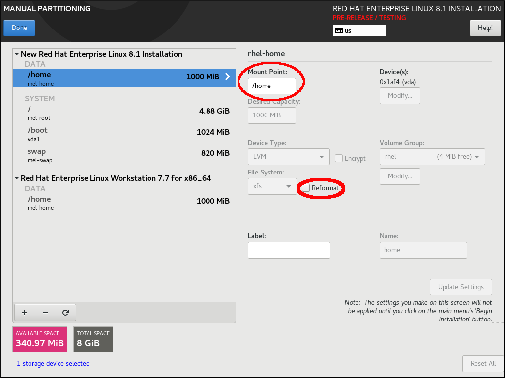
-
Optional: You can also customize various aspects of the
/homepartition required for your Red Hat Enterprise Linux 8 system as described in Customizing a mount point file system. However, to preserve/homefrom your RHEL 7 system, it is necessary to clear the Reformat check box. - After you customized all partitions according to your requirements, click . The Summary of changes dialog box opens.
-
Verify that the Summary of changes dialog box does not show any change for
/home. This means that the/homepartition is preserved. - Click to apply the changes, and return to the Installation Summary window.
6.4.9. Creating a software RAID during the installation
Redundant Arrays of Independent Disks (RAID) devices are constructed from multiple storage devices that are arranged to provide increased performance and, in some configurations, greater fault tolerance. A RAID device is created in one step and disks are added or removed as necessary. You can configure one RAID partition for each physical disk in your system, so that the number of disks available to the installation program determines the levels of RAID device available. For example, if your system has two disks, you cannot create a RAID 10 device, as it requires a minimum of three separate disks. To optimize your system’s storage performance and reliability, RHEL supports software RAID 0, RAID 1, RAID 4, RAID 5, RAID 6, and RAID 10 types with LVM and LVM Thin Provisioning to set up storage on the installed system.
On 64-bit IBM Z, the storage subsystem uses RAID transparently. You do not have to configure software RAID manually.
Prerequisites
- You have selected two or more disks for installation before RAID configuration options are visible. Depending on the RAID type you want to create, at least two disks are required.
- You have created a mount point. By configuring a mount point, you can configure the RAID device.
- You have selected the radio button on the Installation Destination window.
Procedure
- From the left pane of the Manual Partitioning window, select the required partition.
- Under the Device(s) section, click . The Configure Mount Point dialog box opens.
- Select the disks that you want to include in the RAID device and click .
- Click the Device Type drop-down menu and select RAID.
- Click the File System drop-down menu and select your preferred file system type.
- Click the RAID Level drop-down menu and select your preferred level of RAID.
- Click to save your changes.
- Click to apply the settings to return to the Installation Summary window.
6.4.10. Creating an LVM logical volume
Logical Volume Manager (LVM) presents a simple logical view of underlying physical storage space, such as disks or LUNs. Partitions on physical storage are represented as physical volumes that you can group together into volume groups. You can divide each volume group into multiple logical volumes, each of which is analogous to a standard disk partition. Therefore, LVM logical volumes function as partitions that can span multiple physical disks.
- LVM configuration is available only in the graphical installation program. During text-mode installation, LVM configuration is not available.
-
To create an LVM configuration, press Ctrl+Alt+F2 to use a shell prompt in a different virtual console. You can run
vgcreateandlvmcommands in this shell. To return to the text-mode installation, press Ctrl+Alt+F1.
Procedure
From the Manual Partitioning window, create a new mount point by using any of the following options:
- Use the Click here to create them automatically option or click the + button.
- Select Mount Point from the drop-down list or enter manually.
Enter the size of the file system in to the Desired Capacity field; for example, 70 GiB for
/, 1 GiB for/boot.Note: Skip this step to use the existing mount point.
- Select the mount point.
Select
LVMin the drop-down menu. The Volume Group drop-down menu is displayed with the newly-created volume group name.NoteYou cannot specify the size of the volume group’s physical extents in the configuration dialog. The size is always set to the default value of 4 MiB. If you want to create a volume group with different physical extents, you must create it manually by switching to an interactive shell and using the
vgcreatecommand, or use a Kickstart file with thevolgroup --pesize=sizecommand. For more information about Kickstart, see the Automatically installing RHEL.- Click to return to the Installation Summary window.
6.4.11. Configuring an LVM logical volume
You can configure a newly-created LVM logical volume based on your requirements.
Placing the /boot partition on an LVM volume is not supported.
Procedure
From the Manual Partitioning window, create a mount point by using any of the following options:
- Use the Click here to create them automatically option or click the + button.
- Select Mount Point from the drop-down list or enter manually.
Enter the size of the file system in to the Desired Capacity field; for example, 70 GiB for
/, 1 GiB for/boot.Note: Skip this step to use the existing mount point.
- Select the mount point.
-
Click the Device Type drop-down menu and select
LVM. The Volume Group drop-down menu is displayed with the newly-created volume group name. Click to configure the newly-created volume group. The Configure Volume Group dialog box opens.
NoteYou cannot specify the size of the volume group’s physical extents in the configuration dialog. The size is always set to the default value of 4 MiB. If you want to create a volume group with different physical extents, you must create it manually by switching to an interactive shell and using the
vgcreatecommand, or use a Kickstart file with thevolgroup --pesize=sizecommand. For more information, see the Automatically installing RHEL document.Optional: From the RAID Level drop-down menu, select the RAID level that you require.
The available RAID levels are the same as with actual RAID devices.
- Select the Encrypt check box to mark the volume group for encryption.
From the Size policy drop-down menu, select any of the following size policies for the volume group:
The available policy options are:
- Automatic
- The size of the volume group is set automatically so that it is large enough to contain the configured logical volumes. This is optimal if you do not need free space within the volume group.
- As large as possible
- The volume group is created with maximum size, regardless of the size of the configured logical volumes it contains. This is optimal if you plan to keep most of your data on LVM and later need to increase the size of some existing logical volumes, or if you need to create additional logical volumes within this group.
- Fixed
- You can set an exact size of the volume group. Any configured logical volumes must then fit within this fixed size. This is useful if you know exactly how large you need the volume group to be.
- Click to apply the settings and return to the Manual Partitioning window.
- Click to save your changes.
- Click to return to the Installation Summary window.
6.4.12. Advice on partitions
There is no best way to partition every system; the optimal setup depends on how you plan to use the system being installed. However, the following tips may help you find the optimal layout for your needs:
- Create partitions that have specific requirements first, for example, if a particular partition must be on a specific disk.
-
Consider encrypting any partitions and volumes which might contain sensitive data. Encryption prevents unauthorized people from accessing the data on the partitions, even if they have access to the physical storage device. In most cases, you should at least encrypt the
/homepartition, which contains user data. -
In some cases, creating separate mount points for directories other than
/,/bootand/homemay be useful; for example, on a server running aMySQLdatabase, having a separate mount point for/var/lib/mysqlallows you to preserve the database during a re-installation without having to restore it from backup afterward. However, having unnecessary separate mount points will make storage administration more difficult. -
Some special restrictions apply to certain directories with regards to which partitioning layouts can be placed. Notably, the
/bootdirectory must always be on a physical partition (not on an LVM volume). - If you are new to Linux, consider reviewing the Linux Filesystem Hierarchy Standard for information about various system directories and their contents.
- Each kernel requires approximately: 60MiB (initrd 34MiB, 11MiB vmlinuz, and 5MiB System.map)
- For rescue mode: 100MiB (initrd 76MiB, 11MiB vmlinuz, and 5MiB System map)
When
kdumpis enabled in system it will take approximately another 40MiB (another initrd with 33MiB)The default partition size of 1 GiB for
/bootshould suffice for most common use cases. However, increase the size of this partition if you are planning on retaining multiple kernel releases or errata kernels.-
The
/vardirectory holds content for a number of applications, including the Apache web server, and is used by the YUM package manager to temporarily store downloaded package updates. Make sure that the partition or volume containing/varhas at least 5 GiB. -
The
/usrdirectory holds the majority of software on a typical Red Hat Enterprise Linux installation. The partition or volume containing this directory should therefore be at least 5 GiB for minimal installations, and at least 10 GiB for installations with a graphical environment. If
/usror/varis partitioned separately from the rest of the root volume, the boot process becomes much more complex because these directories contain boot-critical components. In some situations, such as when these directories are placed on an iSCSI drive or an FCoE location, the system may either be unable to boot, or it may hang with aDevice is busyerror when powering off or rebooting.This limitation only applies to
/usror/var, not to directories under them. For example, a separate partition for/var/wwwworks without issues.ImportantSome security policies require the separation of
/usrand/var, even though it makes administration more complex.-
Consider leaving a portion of the space in an LVM volume group unallocated. This unallocated space gives you flexibility if your space requirements change but you do not wish to remove data from other volumes. You can also select the
LVM Thin Provisioningdevice type for the partition to have the unused space handled automatically by the volume. - The size of an XFS file system cannot be reduced - if you need to make a partition or volume with this file system smaller, you must back up your data, destroy the file system, and create a new, smaller one in its place. Therefore, if you plan to alter your partitioning layout later, you should use the ext4 file system instead.
-
Use Logical Volume Manager (LVM) if you anticipate expanding your storage by adding more disks or expanding virtual machine disks after the installation. With LVM, you can create physical volumes on the new drives, and then assign them to any volume group and logical volume as you see fit - for example, you can easily expand your system’s
/home(or any other directory residing on a logical volume). - Creating a BIOS Boot partition or an EFI System Partition may be necessary, depending on your system’s firmware, boot drive size, and boot drive disk label. Note that you cannot create a BIOS Boot or EFI System Partition in graphical installation if your system does not require one - in that case, they are hidden from the menu.
-
If you need to make any changes to your storage configuration after the installation, Red Hat Enterprise Linux repositories offer several different tools which can help you do this. If you prefer a command-line tool, try
system-storage-manager.
6.5. Selecting the base environment and additional software
Use the Software Selection window to select the software packages that you require. The packages are organized by Base Environment and Additional Software.
- Base Environment contains predefined packages. You can select only one base environment, for example, Server with GUI (default), Server, Minimal Install, Workstation, Custom operating system, Virtualization Host. The availability is dependent on the installation ISO image that is used as the installation source.
- Additional Software for Selected Environment contains additional software packages for the base environment. You can select multiple software packages.
Use a predefined environment and additional software to customize your system. However, in a standard installation, you cannot select individual packages to install. To view the packages contained in a specific environment, see the repository/repodata/*-comps-repository.architecture.xml file on your installation source media (DVD, CD, USB). The XML file contains details of the packages installed as part of a base environment. Available environments are marked by the <environment> tag, and additional software packages are marked by the <group> tag.
If you are unsure about which packages to install, select the Minimal Install base environment. Minimal install installs a basic version of Red Hat Enterprise Linux with only a minimal amount of additional software. After the system finishes installing and you log in for the first time, you can use the YUM package manager to install additional software. For more information about YUM package manager, see the Configuring basic system settings document.
-
Use the
yum group listcommand from any RHEL 8 system to view the list of packages being installed on the system as a part of software selection. For more information, see Configuring basic system settings. -
If you need to control which packages are installed, you can use a Kickstart file and define the packages in the
%packagessection.
Prerequisites
- You have configured the installation source.
- The installation program has downloaded package metadata.
- The Installation Summary window is open.
Procedure
- From the Installation Summary window, click Software Selection. The Software Selection window opens.
From the Base Environment pane, select a base environment. You can select only one base environment, for example, Server with GUI (default), Server, Minimal Install, Workstation, Custom Operating System, Virtualization Host. By default, the Server with GUI base environment is selected.
Figure 6.3. Red Hat Enterprise Linux Software Selection

- From the Additional Software for Selected Environment pane, select one or more options.
- Click to apply the settings and return to graphical installations.
6.6. Optional: Configuring the network and host name
Use the Network and Host name window to configure network interfaces. Options that you select here are available both during the installation for tasks such as downloading packages from a remote location, and on the installed system.
Follow the steps in this procedure to configure your network and host name.
Procedure
- From the Installation Summary window, click .
- From the list in the left-hand pane, select an interface. The details are displayed in the right-hand pane.
Toggle the switch to enable or disable the selected interface.
You cannot add or remove interfaces manually.
- Click to add a virtual network interface, which can be either: Team, Bond, Bridge, or VLAN.
- Click to remove a virtual interface.
- Click to change settings such as IP addresses, DNS servers, or routing configuration for an existing interface (both virtual and physical).
Type a host name for your system in the Host Name field.
The host name can either be a fully qualified domain name (FQDN) in the format
hostname.domainname, or a short host name without the domain. Many networks have a Dynamic Host Configuration Protocol (DHCP) service that automatically supplies connected systems with a domain name. To allow the DHCP service to assign the domain name to this system, specify only the short host name.Host names can only contain alphanumeric characters and
-or.. Host name should be equal to or less than 64 characters. Host names cannot start or end with-and.. To be compliant with DNS, each part of a FQDN should be equal to or less than 63 characters and the FQDN total length, including dots, should not exceed 255 characters.The value
localhostmeans that no specific static host name for the target system is configured, and the actual host name of the installed system is configured during the processing of the network configuration, for example, by NetworkManager using DHCP or DNS.When using static IP and host name configuration, it depends on the planned system use case whether to use a short name or FQDN. Red Hat Identity Management configures FQDN during provisioning but some 3rd party software products may require a short name. In either case, to ensure availability of both forms in all situations, add an entry for the host in
/etc/hostsin the formatIP FQDN short-alias.- Click to apply the host name to the installer environment.
- Alternatively, in the Network and Hostname window, you can choose the Wireless option. Click in the right-hand pane to select your wifi connection, enter the password if required, and click .
6.6.1. Adding a virtual network interface
You can add a virtual network interface.
Procedure
- From the Network & Host name window, click the button to add a virtual network interface. The Add a device dialog opens.
Select one of the four available types of virtual interfaces:
- Bond: NIC (Network Interface Controller) Bonding, a method to bind multiple physical network interfaces together into a single bonded channel.
- Bridge: Represents NIC Bridging, a method to connect multiple separate networks into one aggregate network.
- Team: NIC Teaming, a new implementation to aggregate links, designed to provide a small kernel driver to implement the fast handling of packet flows, and various applications to do everything else in user space.
- Vlan (Virtual LAN): A method to create multiple distinct broadcast domains which are mutually isolated.
Select the interface type and click . An editing interface dialog box opens, allowing you to edit any available settings for your chosen interface type.
For more information, see Editing network interface.
- Click to confirm the virtual interface settings and return to the Network & Host name window.
- Optional: To change the settings of a virtual interface, select the interface and click .
6.6.2. Editing network interface configuration
You can edit the configuration of a typical wired connection used during installation. Configuration of other types of networks is broadly similar, although the specific configuration parameters might be different.
On 64-bit IBM Z, you cannot add a new connection as the network subchannels need to be grouped and set online beforehand, and this is currently done only in the booting phase.
Procedure
To configure a network connection manually, select the interface from the Network and Host name window and click .
An editing dialog specific to the selected interface opens. The options present depend on the connection type - the available options are slightly different depending on whether the connection type is a physical interface (wired or wireless network interface controller) or a virtual interface (Bond, Bridge, Team, or Vlan) that was previously configured in Adding a virtual interface.
6.6.3. Enabling or Disabling the Interface Connection
You can enable or disable specific interface connections.
Procedure
- Click the General tab.
-
Select the Connect automatically with priority check box to enable connection by default. Keep the default priority setting at
0. Optional: Enable or disable all users on the system from connecting to this network by using the All users may connect to this network option. If you disable this option, only
rootwill be able to connect to this network.ImportantWhen enabled on a wired connection, the system automatically connects during startup or reboot. On a wireless connection, the interface attempts to connect to any known wireless networks in range. For further information about NetworkManager, including the
nm-connection-editortool, see the Configuring and managing networking document.Click to apply the changes and return to the Network and Host name window.
It is not possible to only allow a specific user other than
rootto use this interface, as no other users are created at this point during the installation. If you need a connection for a different user, you must configure it after the installation.
6.6.4. Setting up Static IPv4 or IPv6 Settings
By default, both IPv4 and IPv6 are set to automatic configuration depending on current network settings. This means that addresses such as the local IP address, DNS address, and other settings are detected automatically when the interface connects to a network. In many cases, this is sufficient, but you can also provide static configuration in the IPv4 Settings and IPv6 Settings tabs. Complete the following steps to configure IPv4 or IPv6 settings:
Procedure
- To set static network configuration, navigate to one of the IPv Settings tabs and from the Method drop-down menu, select a method other than Automatic, for example, Manual. The Addresses pane is enabled.
- Optional: In the IPv6 Settings tab, you can also set the method to Ignore to disable IPv6 on this interface.
- Click and enter your address settings.
-
Type the IP addresses in the Additional DNS servers field; it accepts one or more IP addresses of DNS servers, for example,
10.0.0.1,10.0.0.8. Select the Require IPvX addressing for this connection to complete check box.
Selecting this option in the IPv4 Settings or IPv6 Settings tabs allow this connection only if IPv4 or IPv6 was successful. If this option remains disabled for both IPv4 and IPv6, the interface is able to connect if configuration succeeds on either IP protocol.
- Click to apply the changes and return to the Network & Host name window.
6.6.5. Configuring Routes
You can control the access of specific connections by configuring routes.
Procedure
- In the IPv4 Settings and IPv6 Settings tabs, click to configure routing settings for a specific IP protocol on an interface. An editing routes dialog specific to the interface opens.
- Click to add a route.
- Select the Ignore automatically obtained routes check box to configure at least one static route and to disable all routes not specifically configured.
Select the Use this connection only for resources on its network check box to prevent the connection from becoming the default route.
This option can be selected even if you did not configure any static routes. This route is used only to access certain resources, such as intranet pages that require a local or VPN connection. Another (default) route is used for publicly available resources. Unlike the additional routes configured, this setting is transferred to the installed system. This option is useful only when you configure more than one interface.
- Click to save your settings and return to the editing routes dialog that is specific to the interface.
- Click to apply the settings and return to the Network and Host Name window.
6.7. Optional: Configuring the keyboard layout
You can configure the keyboard layout from the Installation Summary screen.
If you use a layout that cannot accept Latin characters, such as Russian, add the English (United States) layout and configure a keyboard combination to switch between the two layouts. If you select a layout that does not have Latin characters, you might be unable to enter a valid root password and user credentials later in the installation process. This might prevent you from completing the installation.
Procedure
- From the Installation Summary window, click Keyboard.
- Click to open the Add a Keyboard Layout window to change to a different layout.
- Select a layout by browsing the list or use the Search field.
- Select the required layout and click . The new layout appears under the default layout.
- Click to optionally configure a keyboard switch that you can use to cycle between available layouts. The Layout Switching Options window opens.
- To configure key combinations for switching, select one or more key combinations and click to confirm your selection.
- Optional: When you select a layout, click the Keyboard button to open a new dialog box displaying a visual representation of the selected layout.
- Click to apply the settings and return to graphical installations.
6.8. Optional: Configuring the language support
You can change the language settings from the Installation Summary screen.
Procedure
- From the Installation Summary window, click Language Support. The Language Support window opens. The left pane lists the available language groups. If at least one language from a group is configured, a check mark is displayed and the supported language is highlighted.
- From the left pane, click a group to select additional languages, and from the right pane, select regional options. Repeat this process for all the languages that you want to configure.
- Optional: Search the language group by typing in the text box, if required.
- Click to apply the settings and return to graphical installations.
6.10. Optional: Subscribing the system and activating Red Hat Insights
Red Hat Insights is a Software-as-a-Service (SaaS) offering that provides continuous, in-depth analysis of registered Red Hat-based systems to proactively identify threats to security, performance and stability across physical, virtual and cloud environments, and container deployments. By registering your RHEL system in Red Hat Insights, you gain access to predictive analytics, security alerts, and performance optimization tools, enabling you to maintain a secure, efficient, and stable IT environment.
You can register to Red Hat by using either your Red Hat account or your activation key details. You can connect your system to Red hat Insights by using the Connect to Red Hat option.
Procedure
- From the Installation Summary screen, under Software, click Connect to Red Hat.
Select Account or Activation Key.
- If you select Account, enter your Red Hat Customer Portal username and password details.
If you select Activation Key, enter your organization ID and activation key.
You can enter more than one activation key, separated by a comma, as long as the activation keys are registered to your subscription.
Select the Set System Purpose check box.
- If the account has Simple content access mode enabled, setting the system purpose values is still important for accurate reporting of consumption in the subscription services.
- If your account is in the entitlement mode, system purpose enables the entitlement server to determine and automatically attach the most appropriate subscription to satisfy the intended use of the Red Hat Enterprise Linux 8 system.
- Select the required Role, SLA, and Usage from the corresponding drop-down lists.
- The Connect to Red Hat Insights check box is enabled by default. Clear the check box if you do not want to connect to Red Hat Insights.
Optional: Expand Options.
- Select the Use HTTP proxy check box if your network environment only allows external Internet access or access to content servers through an HTTP proxy. Clear the Use HTTP proxy check box if an HTTP proxy is not used.
If you are running Satellite Server or performing internal testing, select the Custom Server URL and Custom base URL check boxes and enter the required details.
Important-
The Custom Server URL field does not require the HTTP protocol, for example
nameofhost.com. However, the Custom base URL field requires the HTTP protocol. - To change the Custom base URL after registration, you must unregister, provide the new details, and then re-register.
-
The Custom Server URL field does not require the HTTP protocol, for example
Click to register the system. When the system is successfully registered and subscriptions are attached, the Connect to Red Hat window displays the attached subscription details.
Depending on the amount of subscriptions, the registration and attachment process might take up to a minute to complete.
Click to return to the Installation Summary window.
A Registered message is displayed under Connect to Red Hat.
6.11. Optional: Using network-based repositories for the installation
You can configure an installation source from either auto-detected installation media, Red Hat CDN, or the network. When the Installation Summary window first opens, the installation program attempts to configure an installation source based on the type of media that was used to boot the system. The full Red Hat Enterprise Linux Server DVD configures the source as local media.
Prerequisites
- You have downloaded the full installation DVD ISO or minimal installation Boot ISO image from the Product Downloads page.
- You have created bootable installation media.
- The Installation Summary window is open.
Procedure
From the Installation Summary window, click Installation Source. The Installation Source window opens.
- Review the Auto-detected installation media section to verify the details. This option is selected by default if you started the installation program from media containing an installation source, for example, a DVD.
- Click to check the media integrity.
Review the Additional repositories section and note that the AppStream check box is selected by default.
The BaseOS and AppStream repositories are installed as part of the full installation image. Do not disable the AppStream repository check box if you want a full Red Hat Enterprise Linux 8 installation.
- Optional: Select the Red Hat CDN option to register your system, attach RHEL subscriptions, and install RHEL from the Red Hat Content Delivery Network (CDN).
Optional: Select the On the network option to download and install packages from a network location instead of local media. This option is available only when a network connection is active. See Configuring network and host name options for information about how to configure network connections in the GUI.
NoteIf you do not want to download and install additional repositories from a network location, proceed to Configuring software selection.
- Select the On the network drop-down menu to specify the protocol for downloading packages. This setting depends on the server that you want to use.
-
Type the server address (without the protocol) into the address field. If you choose NFS, a second input field opens where you can specify custom NFS mount options. This field accepts options listed in the
nfs(5)man page on your system. When selecting an NFS installation source, specify the address with a colon (
:) character separating the host name from the path. For example,server.example.com:/path/to/directory.The following steps are optional and are only required if you use a proxy for network access.
- Click to configure a proxy for an HTTP or HTTPS source.
- Select the Enable HTTP proxy check box and type the URL into the Proxy Host field.
- Select the Use Authentication check box if the proxy server requires authentication.
- Type in your user name and password.
Click to finish the configuration and exit the Proxy Setup… dialog box.
NoteIf your HTTP or HTTPS URL refers to a repository mirror, select the required option from the URL type drop-down list. All environments and additional software packages are available for selection when you finish configuring the sources.
- Click to add a repository.
- Click to delete a repository.
- Click the icon to revert the current entries to the setting when you opened the Installation Source window.
To activate or deactivate a repository, click the check box in the Enabled column for each entry in the list.
You can name and configure your additional repository in the same way as the primary repository on the network.
- Click to apply the settings and return to the Installation Summary window.
6.12. Optional: Configuring Kdump kernel crash-dumping mechanism
Kdump is a kernel crash-dumping mechanism. In the event of a system crash, Kdump captures the contents of the system memory at the moment of failure. This captured memory can be analyzed to find the cause of the crash. If Kdump is enabled, it must have a small portion of the system’s memory (RAM) reserved to itself. This reserved memory is not accessible to the main kernel.
Procedure
- From the Installation Summary window, click Kdump. The Kdump window opens.
- Select the Enable kdump check box.
- Select either the Automatic or Manual memory reservation setting.
- If you select Manual, enter the amount of memory (in megabytes) that you want to reserve in the Memory to be reserved field using the + and - buttons. The Usable System Memory readout below the reservation input field shows how much memory is accessible to your main system after reserving the amount of RAM that you select.
- Click to apply the settings and return to graphical installations.
The amount of memory that you reserve is determined by your system architecture (AMD64 and Intel 64 have different requirements than IBM Power) as well as the total amount of system memory. In most cases, automatic reservation is satisfactory.
Additional settings, such as the location where kernel crash dumps will be saved, can only be configured after the installation using either the system-config-kdump graphical interface, or manually in the /etc/kdump.conf configuration file.
6.13. Optional: Selecting a security profile
You can apply security policy during your Red Hat Enterprise Linux 8 installation and configure it to use on your system before the first boot.
6.13.1. About security policy
The Red Hat Enterprise Linux includes OpenSCAP suite to enable automated configuration of the system in alignment with a particular security policy. The policy is implemented using the Security Content Automation Protocol (SCAP) standard. The packages are available in the AppStream repository. However, by default, the installation and post-installation process does not enforce any policies and therefore does not involve any checks unless specifically configured.
Applying a security policy is not a mandatory feature of the installation program. If you apply a security policy to the system, it is installed using restrictions defined in the profile that you selected. The openscap-scanner and scap-security-guide packages are added to your package selection, providing a preinstalled tool for compliance and vulnerability scanning.
When you select a security policy, the Anaconda GUI installer requires the configuration to adhere to the policy’s requirements. There might be conflicting package selections, as well as separate partitions defined. Only after all the requirements are met, you can start the installation.
At the end of the installation process, the selected OpenSCAP security policy automatically hardens the system and scans it to verify compliance, saving the scan results to the /root/openscap_data directory on the installed system.
By default, the installer uses the content of the scap-security-guide package bundled in the installation image. You can also load external content from an HTTP, HTTPS, or FTP server.
6.13.2. Configuring a security profile
You can configure a security policy from the Installation Summary window.
Prerequisites
- The Installation Summary window is open.
Procedure
- From the Installation Summary window, click Security Profile. The Security Profile window opens.
- To enable security policies on the system, toggle the Apply security policy switch to ON.
- Select one of the profiles listed in the top pane.
Click .
Profile changes that you must apply before installation appear in the bottom pane.
Click to use a custom profile.
A separate window opens allowing you to enter a URL for valid security content.
Click to retrieve the URL.
You can load custom profiles from an HTTP, HTTPS, or FTP server. Use the full address of the content including the protocol, such as http://. A network connection must be active before you can load a custom profile. The installation program detects the content type automatically.
- Click to return to the Security Profile window.
- Click to apply the settings and return to the Installation Summary window.
6.13.3. Profiles not compatible with Server with GUI
Certain security profiles provided as part of the SCAP Security Guide are not compatible with the extended package set included in the Server with GUI base environment. Therefore, do not select Server with GUI when installing systems compliant with one of the following profiles:
| Profile name | Profile ID | Justification | Notes |
|---|---|---|---|
| CIS Red Hat Enterprise Linux 8 Benchmark for Level 2 - Server |
|
Packages | |
| CIS Red Hat Enterprise Linux 8 Benchmark for Level 1 - Server |
|
Packages | |
| Unclassified Information in Non-federal Information Systems and Organizations (NIST 800-171) |
|
The | |
| Protection Profile for General Purpose Operating Systems |
|
The | |
| DISA STIG for Red Hat Enterprise Linux 8 |
|
Packages | To install a RHEL system as a Server with GUI aligned with DISA STIG in RHEL version 8.4 and later, you can use the DISA STIG with GUI profile. |
6.13.4. Deploying baseline-compliant RHEL systems using Kickstart
You can deploy RHEL systems that are aligned with a specific baseline. This example uses Protection Profile for General Purpose Operating System (OSPP).
Prerequisites
-
The
scap-security-guidepackage is installed on your RHEL 8 system.
Procedure
-
Open the
/usr/share/scap-security-guide/kickstart/ssg-rhel8-ospp-ks.cfgKickstart file in an editor of your choice. -
Update the partitioning scheme to fit your configuration requirements. For OSPP compliance, the separate partitions for
/boot,/home,/var,/tmp,/var/log,/var/tmp, and/var/log/auditmust be preserved, and you can only change the size of the partitions. - Start a Kickstart installation as described in Performing an automated installation using Kickstart.
Passwords in Kickstart files are not checked for OSPP requirements.
Verification
To check the current status of the system after installation is complete, reboot the system and start a new scan:
# oscap xccdf eval --profile ospp --report eval_postinstall_report.html /usr/share/xml/scap/ssg/content/ssg-rhel8-ds.xml
Chapter 7. Changing a subscription service
To manage the subscriptions, you can register a RHEL system with either Red Hat Subscription Management Server or Red Hat Satellite Server. If required, you can change the subscription service at a later point. To change the subscription service under which you are registered, unregister the system from the current service and then register it with a new service.
To receive the system updates, register your system with either of the management servers.
This section contains information about how to unregister your RHEL system from the Red Hat Subscription Management Server and Red Hat Satellite Server.
Prerequisites
You have registered your system with any one of the following:
- Red Hat Subscription Management Server
- Red Hat Satellite Server version 6.11
To receive the system updates, register your system with either of the management servers.
7.1. Unregistering from Subscription Management Server
This section contains information about how to unregister a RHEL system from Red Hat Subscription Management Server, using a command line and the Subscription Manager user interface.
7.1.1. Unregistering using command line
Use the unregister command to unregister a RHEL system from Red Hat Subscription Management Server.
Procedure
Run the unregister command as a root user, without any additional parameters.
# subscription-manager unregister- When prompted, provide a root password.
The system is unregistered from the Subscription Management Server, and the status 'The system is currently not registered' is displayed with the button enabled.
To continue uninterrupted services, re-register the system with either of the management services. If you do not register the system with a management service, you may fail to receive the system updates. For more information about registering a system, see Registering your system using the command line.
7.1.2. Unregistering using Subscription Manager user interface
You can unregister a RHEL system from Red Hat Subscription Management Server by using Subscription Manager user interface.
Procedure
- Log in to your system.
- From the top left-hand side of the window, click Activities.
- From the menu options, click the Show Applications icon.
- Click the Red Hat Subscription Manager icon, or enter Red Hat Subscription Manager in the search.
Enter your administrator password in the Authentication Required dialog box. The Subscriptions window appears and displays the current status of Subscriptions, System Purpose, and installed products. Unregistered products display a red X.
Authentication is required to perform privileged tasks on the system.
- Click the button.
The system is unregistered from the Subscription Management Server, and the status 'The system is currently not registered' is displayed with the button enabled.
To continue uninterrupted services, re-register the system with either of the management services. If you do not register the system with a management service, you may fail to receive the system updates. For more information about registering a system, see Registering your system using the Subscription Manager User Interface.
7.2. Unregistering from Satellite Server
To unregister a Red Hat Enterprise Linux system from Satellite Server, remove the system from Satellite Server.
For more information, see Removing a Host from Red Hat Satellite.
Chapter 8. Preparing a system with UEFI Secure Boot enabled to install and boot RHEL beta releases
To enhance the security of your operating system, use the UEFI Secure Boot feature for signature verification when booting a Red Hat Enterprise Linux Beta release on systems having UEFI Secure Boot enabled.
8.1. UEFI Secure Boot and RHEL Beta releases
UEFI Secure Boot requires that the operating system kernel is signed with a recognized private key. UEFI Secure Boot then verifies the signature using the corresponding public key.
For Red Hat Enterprise Linux Beta releases, the kernel is signed with a Red Hat Beta-specific private key. UEFI Secure Boot attempts to verify the signature using the corresponding public key, but because the hardware does not recognize the Beta private key, Red Hat Enterprise Linux Beta release system fails to boot. Therefore, to use UEFI Secure Boot with a Beta release, add the Red Hat Beta public key to your system using the Machine Owner Key (MOK) facility.
8.2. Adding a Beta public key for UEFI Secure Boot
This section contains information about how to add a Red Hat Enterprise Linux Beta public key for UEFI Secure Boot.
Prerequisites
- The UEFI Secure Boot is disabled on the system.
- The Red Hat Enterprise Linux Beta release is installed, and Secure Boot is disabled even after system reboot.
- You are logged in to the system, and the tasks in the Initial Setup window are complete.
Procedure
Begin to enroll the Red Hat Beta public key in the system’s Machine Owner Key (MOK) list:
# mokutil --import /usr/share/doc/kernel-keys/$(uname -r)/kernel-signing-ca.cer$(uname -r)is replaced by the kernel version - for example, 4.18.0-80.el8.x86_64.- Enter a password when prompted.
- Reboot the system and press any key to continue the startup. The Shim UEFI key management utility starts during the system startup.
- Select Enroll MOK.
- Select Continue.
- Select Yes and enter the password. The key is imported into the system’s firmware.
- Select Reboot.
- Enable Secure Boot on the system.
8.3. Removing a Beta public key
If you plan to remove the Red Hat Enterprise Linux Beta release, and install a Red Hat Enterprise Linux General Availability (GA) release, or a different operating system, then remove the Beta public key.
The procedure describes how to remove a Beta public key.
Procedure
Begin to remove the Red Hat Beta public key from the system’s Machine Owner Key (MOK) list:
# mokutil --reset- Enter a password when prompted.
- Reboot the system and press any key to continue the startup. The Shim UEFI key management utility starts during the system startup.
- Select Reset MOK.
- Select Continue.
- Select Yes and enter the password that you had specified in step 2. The key is removed from the system’s firmware.
- Select Reboot.
Appendix A. Boot options reference
You can use the boot options to modify the default behavior of the installation program.
A.1. Installation source boot options
This section describes various installation source boot options.
- inst.repo=
The
inst.repo=boot option specifies the installation source, that is, the location providing the package repositories and a valid.treeinfofile that describes them. For example:inst.repo=cdrom. The target of theinst.repo=option must be one of the following installation media:-
an installable tree, which is a directory structure containing the installation program images, packages, and repository data as well as a valid
.treeinfofile - a DVD (a physical disk present in the system DVD drive)
an ISO image of the full Red Hat Enterprise Linux installation DVD, placed on a disk or a network location accessible to the system.
Use the
inst.repo=boot option to configure different installation methods using different formats. The following table contains details of theinst.repo=boot option syntax:Expand Table A.1. Types and format for the inst.repo= boot option and installation source Source type Boot option format Source format CD/DVD drive
inst.repo=cdrom:<device>Installation DVD as a physical disk. [a]
Mountable device (HDD and USB stick)
inst.repo=hd:<device>:/<path>Image file of the installation DVD.
NFS Server
inst.repo=nfs:[options:]<server>:/<path>Image file of the installation DVD, or an installation tree, which is a complete copy of the directories and files on the installation DVD. [b]
HTTP Server
inst.repo=http://<host>/<path>Installation tree that is a complete copy of the directories and files on the installation DVD.
HTTPS Server
inst.repo=https://<host>/<path>FTP Server
inst.repo=ftp://<username>:<password>@<host>/<path>HMC
inst.repo=hmc[a] If device is left out, installation program automatically searches for a drive containing the installation DVD.[b] The NFS Server option uses NFS protocol version 3 by default. To use a different version, addnfsvers=Xto options, replacing X with the version number that you want to use.
-
an installable tree, which is a directory structure containing the installation program images, packages, and repository data as well as a valid
Set disk device names with the following formats:
-
Kernel device name, for example
/dev/sda1orsdb2 -
File system label, for example
LABEL=FlashorLABEL=RHEL8 -
File system UUID, for example
UUID=8176c7bf-04ff-403a-a832-9557f94e61db
Non-alphanumeric characters must be represented as \xNN, where NN is the hexadecimal representation of the character. For example, \x20 is a white space (" ").
- inst.addrepo=
Use the
inst.addrepo=boot option to add an additional repository that you can use as another installation source along with the main repository (inst.repo=). You can use theinst.addrepo=boot option multiple times during one boot. The following table contains details of theinst.addrepo=boot option syntax.NoteThe
REPO_NAMEis the name of the repository and is required in the installation process. These repositories are only used during the installation process; they are not installed on the installed system.
For more information about unified ISO, see Unified ISO.
| Installation source | Boot option format | Additional information |
|---|---|---|
| Installable tree at a URL |
| Looks for the installable tree at a given URL. |
| Installable tree at an NFS path |
|
Looks for the installable tree at a given NFS path. A colon is required after the host. The installation program passes everything after |
| Installable tree in the installation environment |
|
Looks for the installable tree at the given location in the installation environment. To use this option, the repository must be mounted before the installation program attempts to load the available software groups. The benefit of this option is that you can have multiple repositories on one bootable ISO, and you can install both the main repository and additional repositories from the ISO. The path to the additional repositories is |
| Disk |
| Mounts the given <device> partition and installs from the ISO that is specified by the <path>. If the <path> is not specified, the installation program looks for a valid installation ISO on the <device>. This installation method requires an ISO with a valid installable tree. |
- inst.stage2=
The
inst.stage2=boot option specifies the location of the installation program’s runtime image. This option expects the path to a directory that contains a valid.treeinfofile and reads the runtime image location from the.treeinfofile. If the.treeinfofile is not available, the installation program attempts to load the image fromimages/install.img.When you do not specify the
inst.stage2option, the installation program attempts to use the location specified with theinst.repooption.Use this option when you want to manually specify the installation source in the installation program at a later time. For example, when you want to select the Content Delivery Network (CDN) as an installation source. The installation DVD and Boot ISO already contain a suitable
inst.stage2option to boot the installation program from the respective ISO.If you want to specify an installation source, use the
inst.repo=option instead.NoteBy default, the
inst.stage2=boot option is used on the installation media and is set to a specific label; for example,inst.stage2=hd:LABEL=RHEL-x-0-0-BaseOS-x86_64. If you modify the default label of the file system that contains the runtime image, or if you use a customized procedure to boot the installation system, verify that theinst.stage2=boot option is set to the correct value.- inst.noverifyssl
Use the
inst.noverifysslboot option to prevent the installer from verifying SSL certificates for all HTTPS connections with the exception of additional Kickstart repositories, where--noverifysslcan be set per repository.For example, if your remote installation source is using self-signed SSL certificates, the
inst.noverifysslboot option enables the installer to complete the installation without verifying the SSL certificates.Example when specifying the source using
inst.stage2=inst.stage2=https://hostname/path_to_install_image/ inst.noverifysslExample when specifying the source using
inst.repo=inst.repo=https://hostname/path_to_install_repository/ inst.noverifyssl- inst.stage2.all
Use the
inst.stage2.allboot option to specify several HTTP, HTTPS, or FTP sources. You can use theinst.stage2=boot option multiple times with theinst.stage2.alloption to fetch the image from the sources sequentially until one succeeds. For example:inst.stage2.all inst.stage2=http://hostname1/path_to_install_tree/ inst.stage2=http://hostname2/path_to_install_tree/ inst.stage2=http://hostname3/path_to_install_tree/- inst.dd=
-
The
inst.dd=boot option is used to perform a driver update during the installation. For more information about how to update drivers during installation, see the Updating drivers during installation. - inst.repo=hmc
This option eliminates the requirement of an external network setup and expands the installation options. When booting from a Binary DVD, the installation program prompts you to enter additional kernel parameters. To set the DVD as an installation source, append the
inst.repo=hmcoption to the kernel parameters. The installation program then enables support element (SE) and hardware management console (HMC) file access, fetches the images for stage2 from the DVD, and provides access to the packages on the DVD for software selection.ImportantTo use the
inst.repoboot option, ensure the user is configured with a minimum of Privilege Class B. For more information about the user configuration, see IBM documentation.- proxy=
This boot option is used when performing an installation from a HTTP, HTTPS, and FTP protocol. For example:
[PROTOCOL://][USERNAME[:PASSWORD]@]HOST[:PORT]- inst.nosave=
Use the
inst.nosave=boot option to control the installation logs and related files that are not saved to the installed system, for exampleinput_ks,output_ks,all_ks,logsandall. You can combine multiple values separated by a comma. For example,inst.nosave=Input_ks,logsNoteThe
inst.nosaveboot option is used for excluding files from the installed system that cannot be removed by a Kickstart %post script, such as logs and input/output Kickstart results.input_ks- Disables the ability to save the input Kickstart results.
output_ks- Disables the ability to save the output Kickstart results generated by the installation program.
all_ks- Disables the ability to save the input and output Kickstart results.
logs- Disables the ability to save all installation logs.
all- Disables the ability to save all Kickstart results, and all logs.
- inst.multilib
-
Use the
inst.multilibboot option to set DNF’smultilib_policyto all, instead of best. - inst.memcheck
-
The
inst.memcheckboot option performs a check to verify that the system has enough RAM to complete the installation. If there is not enough RAM, the installation process is stopped. The system check is approximate and memory usage during installation depends on the package selection, user interface, for example graphical or text, and other parameters. - inst.nomemcheck
-
The
inst.nomemcheckboot option does not perform a check to verify if the system has enough RAM to complete the installation. Any attempt to perform the installation with less than the minimum amount of memory is unsupported, and might result in the installation process failing.
A.2. Network boot options
If your scenario requires booting from an image over the network instead of booting from a local image, you can use the following options to customize network booting.
Initialize the network with the dracut tool. For complete list of dracut options, see the dracut.cmdline(7) man page on your system.
- ip=
Use the
ip=boot option to configure one or more network interfaces. To configure multiple interfaces, use one of the following methods;-
use the
ipoption multiple times, once for each interface; to do so, use therd.neednet=1option, and specify a primary boot interface using thebootdevoption. -
use the
ipoption once, and then use Kickstart to set up further interfaces. This option accepts several different formats. The following tables contain information about the most common options.
-
use the
In the following tables:
-
The
ipparameter specifies the client IP address andIPv6requires square brackets, for example 192.0.2.1 or [2001:db8::99]. -
The
gatewayparameter is the default gateway.IPv6requires square brackets. -
The
netmaskparameter is the netmask to be used. This can be either a full netmask (for example, 255.255.255.0) or a prefix (for example, 64). The
hostnameparameter is the host name of the client system. This parameter is optional.Expand Table A.3. Boot option formats to configure the network interface Boot option format Configuration method ip=methodAutomatic configuration of any interface
ip=interface:methodAutomatic configuration of a specific interface
ip=ip::gateway:netmask:hostname:interface:noneStatic configuration, for example, IPv4:
ip=192.0.2.1::192.0.2.254:255.255.255.0:server.example.com:enp1s0:noneIPv6:
ip=[2001:db8::1]::[2001:db8::fffe]:64:server.example.com:enp1s0:noneip=ip::gateway:netmask:hostname:interface:method:mtuAutomatic configuration of a specific interface with an override
Configuration methods for the automatic interface
The method
automatic configuration of a specific interface with an overrideopens the interface using the specified method of automatic configuration, such asdhcp, but overrides the automatically obtained IP address, gateway, netmask, host name or other specified parameters. All parameters are optional, so specify only the parameters that you want to override.The
methodparameter can be any of the following:- DHCP
-
dhcp - IPv6 DHCP
-
dhcp6 - IPv6 automatic configuration
-
auto6 - iSCSI Boot Firmware Table (iBFT)
-
ibft
Note-
If you use a boot option that requires network access, such as
inst.ks=http://host/path, without specifying theipoption, the default value of theipoption isip=dhcp.. -
To connect to an iSCSI target automatically, activate a network device for accessing the target by using the
ip=ibftboot option.
- nameserver=
The
nameserver=option specifies the address of the name server. You can use this option multiple times.NoteThe
ip=parameter requires square brackets. However, an IPv6 address does not work with square brackets. An example of the correct syntax to use for an IPv6 address isnameserver=2001:db8::1.- bootdev=
-
The
bootdev=option specifies the boot interface. This option is mandatory if you use more than oneipoption. - ifname=
The
ifname=options assigns an interface name to a network device with a given MAC address. You can use this option multiple times. The syntax isifname=interface:MAC. For example:ifname=eth0:01:23:45:67:89:abNoteThe
ifname=option is the only supported way to set custom network interface names during installation.- inst.dhcpclass=
-
The
inst.dhcpclass=option specifies the DHCP vendor class identifier. Thedhcpdservice recognizes this value asvendor-class-identifier. The default value isanaconda-$(uname -srm). To ensure theinst.dhcpclass=option is applied correctly, request network activation during the early stage of installation by also adding theipoption. - inst.waitfornet=
-
Using the
inst.waitfornet=SECONDSboot option causes the installation system to wait for network connectivity before installation. The value given in theSECONDSargument specifies the maximum amount of time to wait for network connectivity before timing out and continuing the installation process even if network connectivity is not present. - vlan=
Use the
vlan=option to configure a Virtual LAN (VLAN) device on a specified interface with a given name. The syntax isvlan=name:interface. For example:vlan=vlan5:enp0s1This configures a VLAN device named
vlan5on theenp0s1interface. The name can take the following forms:
-
VLAN_PLUS_VID:
vlan0005 -
VLAN_PLUS_VID_NO_PAD:
vlan5 -
DEV_PLUS_VID:
enp0s1.0005 DEV_PLUS_VID_NO_PAD:
enp0s1.5- bond=
Use the
bond=option to configure a bonding device with the following syntax:bond=name[:interfaces][:options]. Replace name with the bonding device name, interfaces with a comma-separated list of physical (Ethernet) interfaces, and options with a comma-separated list of bonding options. For example:bond=bond0:enp0s1,enp0s2:mode=active-backup,tx_queues=32,downdelay=5000For a list of available options, execute the
modinfobonding command.- team=
Use the
team=option to configure a team device with the following syntax:team=name:interfaces. Replace name with the desired name of the team device and interfaces with a comma-separated list of physical (Ethernet) devices to be used as underlying interfaces in the team device. For example:team=team0:enp0s1,enp0s2- bridge=
Use the
bridge=option to configure a bridge device with the following syntax:bridge=name:interfaces. Replace name with the desired name of the bridge device and interfaces with a comma-separated list of physical (Ethernet) devices to be used as underlying interfaces in the bridge device. For example:bridge=bridge0:enp0s1,enp0s2
A.3. Console boot options
This section describes how to configure boot options for your console, monitor display, and keyboard.
- console=
-
Use the
console=option to specify a device that you want to use as the primary console. For example, to use a console on the first serial port, useconsole=ttyS0. When using theconsole=argument, the installation starts with a text UI. If you must use theconsole=option multiple times, the boot message is displayed on all specified console. However, the installation program uses only the last specified console. For example, if you specifyconsole=ttyS0 console=ttyS1, the installation program usesttyS1. - inst.lang=
-
Use the
inst.lang=option to set the language that you want to use during the installation. To view the list of locales, enter the commandlocale -a | grep _or thelocalectl list-locales | grep _command. - inst.singlelang
-
Use the
inst.singlelangoption to install in single language mode, which results in no available interactive options for the installation language and language support configuration. If a language is specified using theinst.langboot option or thelangKickstart command, then it is used. If no language is specified, the installation program defaults toen_US.UTF-8. - inst.geoloc=
Use the
inst.geoloc=option to configure geolocation usage in the installation program. Geolocation is used to preset the language and time zone, and uses the following syntax:inst.geoloc=value. Thevaluecan be any of the following parameters:-
Disable geolocation:
inst.geoloc=0 -
Use the Fedora GeoIP API:
inst.geoloc=provider_fedora_geoip. Use the Hostip.info GeoIP API:
inst.geoloc=provider_hostip.If you do not specify the
inst.geoloc=option, the default option isprovider_fedora_geoip.
-
Disable geolocation:
- inst.keymap=
-
Use the
inst.keymap=option to specify the keyboard layout to use for the installation. - inst.cmdline
-
Use the
inst.cmdlineoption to force the installation program to run in command-line mode. This mode does not allow any interaction, and you must specify all options in a Kickstart file or on the command line. - inst.graphical
-
Use the
inst.graphicaloption to force the installation program to run in graphical mode. The graphical mode is the default. - inst.text
-
Use the
inst.textoption to force the installation program to run in text mode instead of graphical mode. - inst.noninteractive
-
Use the
inst.noninteractiveboot option to run the installation program in a non-interactive mode. User interaction is not permitted in the non-interactive mode, andinst.noninteractiveyou can use theinst.nointeractiveoption with a graphical or text installation. When you use theinst.noninteractiveoption in text mode, it behaves the same as theinst.cmdlineoption. - inst.resolution=
-
Use the
inst.resolution=option to specify the screen resolution in graphical mode. The format isNxM, where N is the screen width and M is the screen height (in pixels). The recommended resolution is 1024x768. - inst.vnc
-
Use the
inst.vncoption to run the graphical installation using Virtual Network Computing (VNC). You must use a VNC client application to interact with the installation program. When VNC sharing is enabled, multiple clients can connect. A system installed using VNC starts in text mode. - inst.vncpassword=
-
Use the
inst.vncpassword=option to set a password on the VNC server that is used by the installation program. - inst.vncconnect=
-
Use the
inst.vncconnect=option to connect to a listening VNC client at the given host location, for example,inst.vncconnect=<host>[:<port>]The default port is 5900. You can use this option by entering the commandvncviewer -listen. - inst.xdriver=
-
Use the
inst.xdriver=option to specify the name of the X driver to use both during installation and on the installed system. - inst.usefbx
-
Use the
inst.usefbxoption to prompt the installation program to use the frame buffer X driver instead of a hardware-specific driver. This option is equivalent to theinst.xdriver=fbdevoption. - modprobe.blacklist=
Use the
modprobe.blacklist=option to blocklist or completely disable one or more drivers. Drivers (mods) that you disable using this option cannot load when the installation starts. After the installation finishes, the installed system retains these settings. You can find a list of the blocklisted drivers in the/etc/modprobe.d/directory. Use a comma-separated list to disable multiple drivers. For example:modprobe.blacklist=ahci,firewire_ohciNoteYou can use
modprobe.blacklistin combination with the different command line options. For example, use it with theinst.ddoption to ensure that an updated version of an existing driver is loaded from a driver update disc:modprobe.blacklist=virtio_blk- inst.xtimeout=
-
Use the
inst.xtimeout=option to specify the timeout in seconds for starting X server. - inst.sshd
Use the
inst.sshdoption to start thesshdservice during installation, so that you can connect to the system during the installation using SSH, and monitor the installation progress. For more information about SSH, see thessh(1)man page on your system. By default, thesshdoption is automatically started only on the 64-bit IBM Z architecture. On other architectures,sshdis not started unless you use theinst.sshdoption.NoteDuring installation, the root account has no password by default. You can set a root password during installation with the
sshpwKickstart command.- inst.kdump_addon=
-
Use the
inst.kdump_addon=option to enable or disable the Kdump configuration screen (add-on) in the installation program. This screen is enabled by default; useinst.kdump_addon=offto disable it. Disabling the add-on disables the Kdump screens in both the graphical and text-based interface as well as the%addon com_redhat_kdumpKickstart command.
A.4. Debug boot options
This section describes the options you can use when debugging issues.
- inst.rescue
-
Use the
inst.rescueoption to run the rescue environment for diagnosing and fixing systems. For more information, see the Red Hat Knowledgebase solution repair a filesystem in rescue mode. - inst.updates=
Use the
inst.updates=option to specify the location of theupdates.imgfile that you want to apply during installation. Theupdates.imgfile can be derived from one of several sources.Expand Table A.4. updates.img file sources Source Description Example Updates from a network
Specify the network location of
updates.img. This does not require any modification to the installation tree. To use this method, edit the kernel command line to includeinst.updates.inst.updates=http://website.com/path/to/updates.img.Updates from a disk image
Save an
updates.imgon a floppy drive or a USB key. This can be done only with anext2filesystem type ofupdates.img. To save the contents of the image on your floppy drive, insert the floppy disc and run the command.dd if=updates.img of=/dev/fd0 bs=72k count=20. To use a USB key or flash media, replace/dev/fd0with the device name of your USB flash drive.Updates from an installation tree
If you are using a CD, disk, HTTP, or FTP install, save the
updates.imgin the installation tree so that all installations can detect the.imgfile. The file name must beupdates.img.For NFS installs, save the file in the
images/directory, or in theRHupdates/directory.- inst.loglevel=
Use the
inst.loglevel=option to specify the minimum level of messages logged on a terminal. This option applies only to terminal logging; log files always contain messages of all levels. Possible values for this option from the lowest to highest level are:-
debug -
info -
warning -
error -
critical
-
The default value is info, which means that by default, the logging terminal displays messages ranging from info to critical.
- inst.syslog=
-
Sends log messages to the
syslogprocess on the specified host when the installation starts. You can useinst.syslog=only if the remotesyslogprocess is configured to accept incoming connections. - inst.virtiolog=
-
Use the
inst.virtiolog=option to specify which virtio port (a character device at/dev/virtio-ports/name) to use for forwarding logs. The default value isorg.fedoraproject.anaconda.log.0. - inst.zram=
Controls the usage of zRAM swap during installation. The option creates a compressed block device inside the system RAM and uses it for swap space instead of using the disk. This setup allows the installation program to run with less available memory and improve installation speed. You can configure the
inst.zram=option using the following values:- inst.zram=1 to enable zRAM swap, regardless of system memory size. By default, swap on zRAM is enabled on systems with 2 GiB or less RAM.
- inst.zram=0 to disable zRAM swap, regardless of system memory size. By default, swap on zRAM is disabled on systems with more than 2 GiB of memory.
- rd.live.ram
-
Copies the
stage 2image inimages/install.imginto RAM. Note that this increases the memory required for installation by the size of the image which is usually between 400 and 800MB. - inst.nokill
- Prevent the installation program from rebooting when a fatal error occurs, or at the end of the installation process. Use it capture installation logs which would be lost upon reboot.
- inst.noshell
- Prevent a shell on terminal session 2 (tty2) during installation.
- inst.notmux
- Prevent the use of tmux during installation. The output is generated without terminal control characters and is meant for non-interactive uses.
- inst.remotelog=
-
Sends all the logs to a remote
host:portusing a TCP connection. The connection is retired if there is no listener and the installation proceeds as normal.
A.5. Storage boot options
This section describes the options you can specify to customize booting from a storage device.
- inst.nodmraid
-
Disables
dmraidsupport.
Use this option with caution. If you have a disk that is incorrectly identified as part of a firmware RAID array, it might have some stale RAID metadata on it that must be removed using the appropriate tool such as, dmraid or wipefs.
- inst.nompath
- Disables support for multipath devices. Use this option only if your system has a false-positive that incorrectly identifies a normal block device as a multipath device.
Use this option with caution. Do not use this option with multipath hardware. Using this option to install to a single path of a multipath device is not supported.
- inst.gpt
-
Forces the installation program to install partition information to a GUID Partition Table (GPT) instead of a Master Boot Record (MBR). This option is not valid on UEFI-based systems, unless they are in BIOS compatibility mode. Normally, BIOS-based systems and UEFI-based systems in BIOS compatibility mode attempt to use the MBR schema for storing partitioning information, unless the disk is 2^32 sectors in size or larger. Disk sectors are typically 512 bytes in size, meaning that this is usually equivalent to 2 TiB. The
inst.gptboot option allows a GPT to be written to smaller disks. - inst.wait_for_disks=
-
Use the
inst.wait_for_disks=option to specify the number of seconds installation program to wait for disk devices to appear at the beginning of the installation. Use this option when you use theOEMDRV-labeleddevice to automatically load the Kickstart file or the kernel drivers but the device takes longer time to appear during the boot process. By default, installation program waits for5seconds. Use0seconds to minimize the delay.
A.6. Deprecated boot options
This section contains information about deprecated boot options. These options are still accepted by the installation program but they are deprecated and are scheduled to be removed in a future release of Red Hat Enterprise Linux.
- method
-
The
methodoption is an alias forinst.repo. - dns
-
Use
nameserverinstead ofdns. Note that nameserver does not accept comma-separated lists; use multiple nameserver options instead. - netmask, gateway, hostname
-
The
netmask,gateway, andhostnameoptions are provided as part of theipoption. - ip=bootif
-
A PXE-supplied
BOOTIFoption is used automatically, so there is no requirement to useip=bootif. - ksdevice
Expand Table A.5. Values for the ksdevice boot option Value Information Not present
N/A
ksdevice=linkIgnored as this option is the same as the default behavior
ksdevice=bootifIgnored as this option is the default if
BOOTIF=is presentksdevice=ibftReplaced with
ip=ibft. Seeipfor detailsksdevice=<MAC>Replaced with
BOOTIF=${MAC/:/-}ksdevice=<DEV>Replaced with
bootdev
A.7. Removed boot options
This section contains the boot options that have been removed from Red Hat Enterprise Linux.
dracut provides advanced boot options. For more information about dracut, see the dracut.cmdline(7) man page on your system.
- askmethod, asknetwork
-
initramfsis completely non-interactive, so theaskmethodandasknetworkoptions have been removed. Useinst.repoor specify the appropriate network options. - blacklist, nofirewire
-
The
modprobeoption now handles blocklisting kernel modules. Usemodprobe.blacklist=<mod1>,<mod2>. You can blocklist the firewire module by usingmodprobe.blacklist=firewire_ohci. - inst.headless=
-
The
headless=option specified that the system that is being installed to does not have any display hardware, and that the installation program is not required to look for any display hardware. - inst.decorated
-
The
inst.decoratedoption was used to specify the graphical installation in a decorated window. By default, the window is not decorated, so it does not have a title bar, resize controls, and so on. This option was no longer required. - repo=nfsiso
-
Use the
inst.repo=nfs:option. - serial
-
Use the
console=ttyS0option. - updates
-
Use the
inst.updatesoption. - essid, wepkey, wpakey
- Dracut does not support wireless networking.
- ethtool
- This option was no longer required.
- gdb
-
This option was removed because many options are available for debugging dracut-based
initramfs. - inst.mediacheck
-
Use the
dracut option rd.live.checkoption. - ks=floppy
-
Use the
inst.ks=hd:<device>option. - display
-
For a remote display of the UI, use the
inst.vncoption. - utf8
- This option was no longer required because the default TERM setting behaves as expected.
- noipv6
-
ipv6 is built into the kernel and cannot be removed by the installation program. You can disable ipv6 by using
ipv6.disable=1. This setting is used by the installed system. - upgradeany
- This option was no longer required because the installation program no longer handles upgrades.
Chapter 9. Composing a customized RHEL system image
9.1. RHEL image builder description
To deploy a system, create a system image. To create RHEL system images, use the RHEL image builder tool. You can use RHEL image builder to create customized system images of RHEL, including system images prepared for deployment on cloud platforms. RHEL image builder automatically handles the setup details for each output type and is therefore easier to use and faster to work with than manual methods of image creation. You can access the RHEL image builder functionalities by using the command line in the composer-cli tool, or the graphical user interface in the RHEL web console.
From RHEL 8.3 onward, the osbuild-composer back end replaces lorax-composer. The new service provides REST APIs for image building.
9.1.1. RHEL image builder terminology
RHEL image builder uses the following concepts:
- Blueprint
A blueprint is a description of a customized system image. It lists the packages and customizations that will be part of the system. You can edit blueprints with customizations and save them as a particular version. When you create a system image from a blueprint, the image is associated with the blueprint in the RHEL image builder interface.
Create blueprints in the TOML format.
- Compose
- Composes are individual builds of a system image, based on a specific version of a particular blueprint. Compose as a term refers to the system image, the logs from its creation, inputs, metadata, and the process itself.
- Customizations
- Customizations are specifications for the image that are not packages. This includes users, groups, and SSH keys.
9.1.2. RHEL image builder output formats
RHEL image builder can create images in multiple output formats shown in the following table.
| Description | CLI name | File extension |
|---|---|---|
| QEMU Image |
|
|
| Disk Archive |
|
|
| Amazon Web Services |
|
|
| Microsoft Azure |
|
|
| Google Cloud Platform |
|
|
| VMware vSphere |
|
|
| VMware vSphere |
|
|
| Openstack |
|
|
| RHEL for Edge Commit |
|
|
| RHEL for Edge Container |
|
|
| RHEL for Edge Installer |
|
|
| RHEL for Edge Raw Image |
|
|
| RHEL for Edge Simplified Installer |
|
|
| RHEL for Edge AMI |
|
|
| RHEL for Edge VMDK |
|
|
| RHEL Installer |
|
|
| Oracle Cloud Infrastructure |
|
|
To check the supported types, run the command:
# composer-cli compose types9.1.3. Supported architectures for image builds
RHEL image builder supports building images for the following architectures:
-
AMD and Intel 64-bit (
x86_64) -
ARM64 (
aarch64) -
IBM Z (
s390x) - IBM POWER systems
However, RHEL image builder does not support multi-architecture builds. It only builds images of the same system architecture that it is running on. For example, if RHEL image builder is running on an x86_64 system, it can only build images for the x86_64 architecture.
9.2. Installing RHEL image builder
RHEL image builder is a tool for creating custom system images. Before using RHEL image builder, you must install it.
9.2.1. RHEL image builder system requirements
The host that runs RHEL image builder must meet the following requirements:
| Parameter | Minimal Required Value |
|---|---|
| System type | A dedicated host or virtual machine. Note that RHEL image builder is not supported in containers, including Red Hat Universal Base Images (UBI). |
| Processor | 2 cores |
| Memory | 4 GiB |
| Disk space | 20 GiB of free space in the ` /var/cache/` filesystem |
| Access privileges | root |
| Network | Internet connectivity to the Red Hat Content Delivery Network (CDN). |
If you do not have internet connectivity, use RHEL image builder in isolated networks. For that, you must override the default repositories to point to your local repositories to not connect to Red Hat Content Delivery Network (CDN). Ensure that you have your content mirrored internally or use Red Hat Satellite.
9.2.2. Installing RHEL image builder
Install RHEL image builder to have access to all the osbuild-composer package functionalities.
Prerequisites
- You are logged in to the RHEL host on which you want to install RHEL image builder.
- The host is subscribed to Red Hat Subscription Manager (RHSM) or Red Hat Satellite.
-
You have enabled the
BaseOSandAppStreamrepositories to be able to install the RHEL image builder packages.
Procedure
Install RHEL image builder and other necessary packages:
# yum install osbuild-composer composer-cli cockpit-composer-
osbuild-composer- A service to build customized RHEL operating system images. -
composer-cli- This package enables access to the CLI interface. -
cockpit-composer- This package enables access to the Web UI interface. The web console is installed as a dependency of thecockpit-composerpackage.
-
Enable and start RHEL image builder socket:
# systemctl enable --now osbuild-composer.socketIf you want to use RHEL image builder in the web console, enable and start it.
# systemctl enable --now cockpit.socketThe
osbuild-composerandcockpitservices start automatically on first access.Load the shell configuration script so that the autocomplete feature for the
composer-clicommand starts working immediately without logging out and in:$ source /etc/bash_completion.d/composer-cli
The osbuild-composer package is the new backend engine that will be the preferred default and focus of all new functionality beginning with Red Hat Enterprise Linux 8.3 and later. The previous backend lorax-composer package is considered deprecated, will only receive select fixes for the remainder of the Red Hat Enterprise Linux 8 life cycle and will be omitted from future major releases. It is recommended to uninstall lorax-composer in favor of osbuild-composer.
Verification
Verify that the installation works by running
composer-cli:# composer-cli status show
Troubleshooting
You can use a system journal to track RHEL image builder activities. Additionally, you can find the log messages in the file.
To find the journal output for traceback, run the following commands:
$ journalctl | grep osbuildTo show the local worker, such as the
osbuild-worker@.service, a template service that can start multiple service instances:$ journalctl -u osbuild-worker*To show the running services:
$ journalctl -u osbuild-composer.service
9.2.3. Reverting to lorax-composer RHEL image builder backend
The osbuild-composer backend, though much more extensible, does not currently achieve feature parity with the previous lorax-composer backend.
To revert to the previous backend, follow the steps:
Prerequisites
-
You have installed the
osbuild-composerpackage
Procedure
Remove the osbuild-composer backend.
# yum remove osbuild-composer # yum remove weldr-clientIn the
/etc/yum.conf file, add an exclude entry forosbuild-composerpackage.# cat /etc/yum.conf [main] gpgcheck=1 installonly_limit=3 clean_requirements_on_remove=True best=True skip_if_unavailable=False exclude=osbuild-composer weldr-clientInstall the
lorax-composerpackage.# yum install lorax-composer composer-cliEnable and start the
lorax-composerservice to start after each reboot.# systemctl enable --now lorax-composer.socket # systemctl start lorax-composer
9.3. Creating system images by using RHEL image builder CLI
RHEL image builder is a tool for creating custom system images. To control RHEL image builder and create your custom system images, you can use the command line (CLI) or the web console interface.
9.3.1. Introducing the RHEL image builder command-line interface
You can use the RHEL image builder command-line interface (CLI) to create blueprints, by running the composer-cli command with the suitable options and subcommands.
The workflow for the command line can be summarized as follows:
- Create a blueprint or export (save) an existing blueprint definition to a plain text file
- Edit this file in a text editor
- Import the blueprint text file back into image builder
- Run a compose to build an image from the blueprint
- Export the image file to download it
Apart from the basic subcommands to create a blueprint, the composer-cli command offers many subcommands to examine the state of configured blueprints and composes.
9.3.2. Using RHEL image builder as a non-root user
To run the composer-cli commands as non-root, the user must be in the weldr group.
Prerequisites
- You have created a user
Procedure
To add a user to the
weldrorrootgroups, run the following commands:$ sudo usermod -a -G weldr user $ newgrp weldr
9.3.3. Creating a blueprint by using the command line
You can create a new blueprint by using the RHEL image builder command-line interface (CLI). The blueprint describes the final image and its customizations, such as packages, and kernel customizations.
Prerequisites
-
You are logged in as the root user or a user who is a member of the
weldrgroup
Procedure
Create a plain text file with the following contents:
name = "BLUEPRINT-NAME" description = "LONG FORM DESCRIPTION TEXT" version = "0.0.1" modules = [] groups = []Replace BLUEPRINT-NAME and LONG FORM DESCRIPTION TEXT with a name and description for your blueprint.
Replace 0.0.1 with a version number according to the Semantic Versioning scheme.
For every package that you want to be included in the blueprint, add the following lines to the file:
[[packages]] name = "package-name" version = "package-version"Replace package-name with the name of the package, such as
httpd,gdb-doc, orcoreutils.Optionally, replace package-version with the version to use. This field supports
dnfversion specifications:- For a specific version, use the exact version number such as 8.7.0.
- For the latest available version, use the asterisk *.
- For the latest minor version, use formats such as 8.*.
Customize your blueprints to suit your needs. For example, disable Simultaneous Multi Threading (SMT), add the following lines to the blueprint file:
[customizations.kernel] append = "nosmt=force"For additional customizations available, see Supported Image Customizations.
Note that
[]and[[]]are different data structures expressed in TOML.-
The
[customizations.kernel]header represents a single table that is defined by a collection of keys and their respective value pairs, for example:append = "nosmt=force". -
The
[[packages]]header represents an array of tables. The first instance defines the array and its first table element, for example,name = "package-name"andversion = "package-version", and each subsequent instance creates and defines a new table element in that array, in the order that you defined them.
-
The
- Save the file, for example, as BLUEPRINT-NAME.toml and close the text editor.
Optional: Check if all settings from the Blueprint TOML file have been correctly parsed. Save the blueprint and compare the saved output with the input file:
# composer-cli blueprints save BLUEPRINT-NAME.toml-
Compare the
BLUEPRINT-NAME.tomlsaved file with the input file.
-
Compare the
Push the blueprint:
# composer-cli blueprints push BLUEPRINT-NAME.tomlReplace BLUEPRINT-NAME with the value you used in previous steps.
NoteTo create images using
composer-clias non-root, add your user to theweldrorrootgroups.# usermod -a -G weldr user $ newgrp weldr
Verification
List the existing blueprints to verify that the blueprint has been pushed and exists:
# composer-cli blueprints listDisplay the blueprint configuration you have just added:
# composer-cli blueprints show BLUEPRINT-NAMECheck whether the components and versions listed in the blueprint and their dependencies are valid:
# composer-cli blueprints depsolve BLUEPRINT-NAMEIf RHEL image builder is unable to solve the dependencies of a package from your custom repositories, remove the
osbuild-composercache:$ sudo rm -rf /var/cache/osbuild-composer/* $ sudo systemctl restart osbuild-composer
9.3.4. Editing a blueprint by using the command line
You can edit an existing blueprint on the command line (CLI) to, for example, add a new package, or define a new group, and to create your customized images.
Prerequisites
- You have created a blueprint
Procedure
List the existing blueprints:
# composer-cli blueprints listSave the blueprint to a local text file:
# composer-cli blueprints save BLUEPRINT-NAME- Edit the BLUEPRINT-NAME.toml file with a text editor and make your changes.
Before finishing the edits, verify that the file is a valid blueprint:
Remove the following line from the blueprint, if present:
packages = []- Increase the version number, for example, from 0.0.1 to 0.1.0. Remember that RHEL image builder blueprint versions must use the Semantic Versioning scheme. Note also that if you do not change the version, the patch version component increases automatically.
- Save the file and close the text editor.
Push the blueprint back into RHEL image builder:
# composer-cli blueprints push BLUEPRINT-NAME.tomlNoteTo import the blueprint back into RHEL image builder, supply the file name including the
.tomlextension, while in other commands use only the blueprint name.
Verification
To verify that the contents uploaded to RHEL image builder match your edits, list the contents of blueprint:
# composer-cli blueprints show BLUEPRINT-NAMECheck whether the components and versions listed in the blueprint and their dependencies are valid:
# composer-cli blueprints depsolve BLUEPRINT-NAME
9.3.5. Creating a system image with RHEL image builder on the command line
You can build a customized RHEL image by using the RHEL image builder command-line interface. For that, you must specify a blueprint and an image type. Optionally, you can also specify a distribution. If you do not specify a distribution, it will use the same distribution and version as the host system. The architecture is also the same as the one on the host.
Prerequisites
- You have a blueprint prepared for the image. See Creating a RHEL image builder blueprint by using the command line.
Procedure
Optional: List the image formats you can create:
# composer-cli compose typesStart the compose:
# composer-cli compose start BLUEPRINT-NAME IMAGE-TYPEReplace BLUEPRINT-NAME with the name of the blueprint, and IMAGE-TYPE with the type of the image. For the available values, see the output of the
composer-cli compose typescommand.The compose process starts in the background and shows the composer Universally Unique Identifier (UUID).
The image creation can take up to ten minutes to complete.
To check the status of the compose:
# composer-cli compose statusA finished compose shows the FINISHED status value. To identify your compose in the list, use its UUID.
After the compose process is finished, download the resulting image file:
# composer-cli compose image UUIDReplace UUID with the UUID value shown in the previous steps.
Verification
After you create your image, you can check the image creation progress by using the following commands:
Download the metadata of the image to get a
.tarfile of the metadata for the compose:$ sudo composer-cli compose metadata UUIDDownload the logs of the image:
$ sudo composer-cli compose logs UUIDThe command creates a
.tarfile that contains the logs for the image creation. If the logs are empty, you can check the journal.Check the journal:
$ journalctl | grep osbuildCheck the manifest of the image:
$ sudo cat /var/lib/osbuild-composer/jobs/job_UUID.jsonYou can find the job_UUID.json in the journal.
9.3.6. Basic RHEL image builder command-line commands
The RHEL image builder command-line interface offers the following subcommands.
Blueprint manipulation
- List all available blueprints
# composer-cli blueprints list- Show a blueprint contents in the TOML format
# composer-cli blueprints show <BLUEPRINT-NAME>- Save (export) blueprint contents in the TOML format into a file
BLUEPRINT-NAME.toml # composer-cli blueprints save <BLUEPRINT-NAME>- Remove a blueprint
# composer-cli blueprints delete <BLUEPRINT-NAME>- Push (import) a blueprint file in the TOML format into RHEL image builder
# composer-cli blueprints push <BLUEPRINT-NAME>
Composing images from blueprints
- List the available image types
# composer-cli compose types- Start a compose
# composer-cli compose start <BLUEPRINT> <COMPOSE-TYPE>- List all composes
# composer-cli compose list- List all composes and their status
# composer-cli compose status- Cancel a running compose
# composer-cli compose cancel <COMPOSE-UUID>- Delete a finished compose
# composer-cli compose delete <COMPOSE-UUID>- Show detailed information about a compose
# composer-cli compose info <COMPOSE-UUID>- Download image file of a compose
# composer-cli compose image <COMPOSE-UUID>- See more subcommands and options
# composer-cli help
9.3.7. RHEL image builder blueprint format
RHEL image builder blueprints are presented to the user as plain text in the TOML format.
The elements of a typical blueprint file include the following:
- The blueprint metadata
name = "<BLUEPRINT-NAME>" description = "<LONG FORM DESCRIPTION TEXT>" version = "<VERSION>"The BLUEPRINT-NAME and LONG FORM DESCRIPTION TEXT field are a name and description for your blueprint.
The VERSION is a version number according to the Semantic Versioning scheme, and is present only once for the entire blueprint file.
- Groups to include in the image
[[groups]] name = "group-name"The group entry describes a group of packages to be installed into the image. Groups use the following package categories:
- Mandatory
- Default
Optional
The group-name is the name of the group, for example, anaconda-tools, widget, wheel or users. Blueprints install the mandatory and default packages. There is no mechanism for selecting optional packages.
- Packages to include in the image
[[packages]] name = "<package-name>" version = "<package-version>"package-name is the name of the package, such as httpd, gdb-doc, or coreutils.
package-version is a version to use. This field supports
dnfversion specifications:- For a specific version, use the exact version number such as 8.7.0.
- For latest available version, use the asterisk *.
For a latest minor version, use a format such as 8.*.
Repeat this block for every package to include.
There are no differences between packages and modules in the RHEL image builder tool. Both are treated as RPM package dependencies.
9.3.8. Supported image customizations
You can customize your image by adding customizations to your blueprint, such as:
- Adding an additional RPM package
- Enabling a service
- Customizing a kernel command line parameter.
Between others. You can use several image customizations within blueprints. By using the customizations, you can add packages and groups to the image that are not available in the default packages. To use these options, configure the customizations in the blueprint and import (push) it to RHEL image builder.
9.3.8.1. Selecting a distribution
You can use the distro field to specify the distribution to use when composing your images or solving dependencies in the blueprint. If the distro field is left blank, the blueprint automatically uses the host’s operating system distribution. If you do not specify a distribution, the blueprint uses the host distribution. When you upgrade the host operating system, blueprints without a specified distribution build images by using the upgraded operating system version.
You can build images for older major versions on a newer system. For example, you can use a RHEL 10 host to create RHEL 9 and RHEL 8 images. However, you cannot build images for newer major versions on an older system.
You cannot build an operating system image that differs from the RHEL image builder host. For example, you cannot use a RHEL system to build Fedora or CentOS images.
Customize the blueprint with the RHEL distribution to always build the specified RHEL image:
name = "blueprint_name" description = "blueprint_version" version = "0.1" distro = "different_minor_version"For example:
name = "tmux" description = "tmux image with openssh" version = "1.2.16" distro = "rhel-9.5"
Replace "different_minor_version" to build a different minor version, for example, if you want to build a RHEL 8.10 image, use distro = "rhel-810". On RHEL 8.10 image, you can build minor versions such as RHEL 8.9 and earlier releases.
9.3.8.2. Selecting a package group
Customize the blueprint with package groups. The groups list describes the groups of packages that you want to install into the image. The package groups are defined in the repository metadata. Each group has a descriptive name that is used primarily for display in user interfaces, and an ID that is commonly used in Kickstart files. In this case, you must use the ID to list a group. Groups have three different ways of categorizing their packages: mandatory, default, and optional. Only mandatory and default packages are installed in the blueprints. It is not possible to select optional packages.
The name attribute is a required string and must match exactly the package group id in the repositories.
Currently, there are no differences between packages and modules in osbuild-composer. Both are treated as an RPM package dependency.
Customize your blueprint with a package:
[[groups]] name = "group_name"Replace
group_namewith the name of the group. For example,anaconda-tools:[[groups]] name = "anaconda-tools"
9.3.8.3. Embedding a container
You can customize your blueprint to embed the latest RHEL container. The containers list contains objects with a source, and optionally, the tls-verify attribute.
The container list entries describe the container images to be embedded into the image.
-
source- Mandatory field. It is a reference to the container image at a registry. This example uses theregistry.access.redhat.comregistry. You can specify a tag version. The default tag version is latest. -
name- The name of the container in the local registry. -
tls-verify- Boolean field. The tls-verify boolean field controls the transport layer security. The default value is true.
The embedded containers do not start automatically. To start it, create systemd unit files or quadlets with the files customization.
To embed a container from
registry.access.redhat.com/ubi9/ubi:latestand a container from your host, add the following customization to your blueprint:[[containers]] source = "registry.access.redhat.com/ubi9/ubi:latest" name = "local-name" tls-verify = true [[containers]] source = "localhost/test:latest" local-storage = true
You can access protected container resources by using a containers-auth.json file. See Container registry credentials.
9.3.8.4. Setting the image hostname
The customizations.hostname is an optional string that you can use to configure the final image hostname. This customization is optional, and if you do not set it, the blueprint uses the default hostname.
Customize the blueprint to configure the hostname:
[customizations] hostname = "baseimage"
9.3.8.5. Specifying additional users
Add a user to the image, and optionally, set their SSH key. All fields for this section are optional except for the name.
Procedure
Customize the blueprint to add a user to the image:
[[customizations.user]] name = "USER-NAME" description = "USER-DESCRIPTION" password = "PASSWORD-HASH" key = "PUBLIC-SSH-KEY" home = "/home/USER-NAME/" shell = "/usr/bin/bash" groups = ["users", "wheel"] uid = NUMBER gid = NUMBER[[customizations.user]] name = "admin" description = "Administrator account" password = "$6$CHO2$3rN8eviE2t50lmVyBYihTgVRHcaecmeCk31L..." key = "PUBLIC SSH KEY" home = "/srv/widget/" shell = "/usr/bin/bash" groups = ["widget", "users", "wheel"] uid = 1200 gid = 1200 expiredate = 12345The GID is optional and must already exist in the image. Optionally, a package creates it, or the blueprint creates the GID by using the
[[customizations.group]]entry.Replace PASSWORD-HASH with the actual
password hash. To generate thepassword hash, use a command such as:$ python3 -c 'import crypt,getpass;pw=getpass.getpass();print(crypt.crypt(pw) if (pw==getpass.getpass("Confirm: ")) else exit())'Replace the other placeholders with suitable values.
Enter the
namevalue and omit any lines you do not need.Repeat this block for every user to include.
9.3.8.6. Specifying additional groups
Specify a group for the resulting system image. Both the name and the gid attributes are mandatory.
Customize the blueprint with a group:
[[customizations.group]] name = "GROUP-NAME" gid = NUMBERRepeat this block for every group to include. For example:
[[customizations.group]] name = "widget" gid = 1130
9.3.8.7. Setting SSH key for existing users
You can use customizations.sshkey to set an SSH key for the existing users in the final image. Both user and key attributes are mandatory.
Customize the blueprint by setting an SSH key for existing users:
[[customizations.sshkey]] user = "root" key = "PUBLIC-SSH-KEY"For example:
[[customizations.sshkey]] user = "root" key = "SSH key for root"NoteYou can only configure the
customizations.sshkeycustomization for existing users. To create a user and set an SSH key, see the Specifying additional users customization.
9.3.8.8. Appending a kernel argument
You can append arguments to the boot loader kernel command line. By default, RHEL image builder builds a default kernel into the image. However, you can customize the kernel by configuring it in the blueprint.
Append a kernel boot parameter option to the defaults:
[customizations.kernel] append = "KERNEL-OPTION"For example:
[customizations.kernel] name = "kernel-debug" append = "nosmt=force"
9.3.8.9. Building RHEL images by using the real-time kernel
To build a RHEL image by using the real-time kernel (kernel-rt), you need to override a repository so that you can then build an image in which kernel-rt is correctly selected as the default kernel. Use the .json from the /usr/share/osbuild-composer/repositories/ directory. Then, you can deploy the image that you built to a system and use the real time kernel features.
The real-time kernel runs on AMD64 and Intel 64 server platforms that are certified to run Red Hat Enterprise Linux.
Prerequisites
- Your system is registered and RHEL is attached to a RHEL for Real Time subscription. See Installing RHEL for Real Time using dnf.
Procedure
Create the following directory:
# mkdir /etc/osbuild-composer/repositories/Copy the content from the
/usr/share/osbuild-composer/repositories/rhel-8.version.jsonfile to the new directory:# cp /usr/share/osbuild-composer/repositories/rhel-8.version.json /etc/osbuild-composer/repositoriesEdit the
/etc/osbuild-composer/repositories/rhel-8.version.jsonfile to include the RT kernel repo:# grep -C 6 kernel-rt /etc/osbuild-composer/repositories/rhel-8.version.json "baseurl": "https://cdn.redhat.com/content/dist/rhel8/8.version/x86_64/appstream/os", "gpgkey": "-----BEGIN PGP PUBLIC KEY BLOCK-----\n\nm………..=\n=UZd/\n-----END PGP PUBLIC KEY BLOCK-----\n", "rhsm": true, "check_gpg": true }, { "name": "kernel-rt", "baseurl": "https://cdn.redhat.com/content/dist/rhel8/8.version/x86_64/rt/os", "gpgkey": "-----BEGIN PGP PUBLIC KEY BLOCK-----\n\nmQINBEr………fg==\n=UZd/\n-----END PGP PUBLIC KEY BLOCK-----\n", "rhsm": true, "check_gpg": true },Restart the service:
# systemctl restart osbuild-composerConfirm that the
kernel-rthas been included into the.jsonfile:# composer-cli sources list # composer-cli sources info kernel-rtYou will see the URL that you have previously configured.
Create a blueprint. In the blueprint, add the "[customizations.kernel]" customization. The following is an example that contains the "[customizations.kernel]" in the blueprint:
name = "rt-kernel-image" description = "" version = "2.0.0" modules = [] groups = [] distro = "rhel-8_version_" [[customizations.user]] name = "admin" password = "admin" groups = ["users", "wheel"] [customizations.kernel] name = "kernel-rt" append = ""Push the blueprint to the server:
# composer-cli blueprints push rt-kernel-image.tomlBuild your image from the blueprint you created. The following example builds a (
.qcow2) image:# composer-cli compose start rt-kernel-image qcow2- Deploy the image that you built to the system where you want to use the real time kernel features.
Verification
After booting a VM from the image, verify that the image was built with the
kernel-rtcorrectly selected as the default kernel.$ cat /proc/cmdline BOOT_IMAGE=(hd0,got3)/vmlinuz-5.14.0-362.24.1..el8_version_.x86_64+rt...
9.3.8.10. Setting time zone and NTP
You can customize your blueprint to configure the time zone and the Network Time Protocol (NTP). Both timezone and ntpservers attributes are optional strings. If you do not customize the time zone, the system uses Universal Time, Coordinated (UTC). If you do not set NTP servers, the system uses the default distribution.
Customize the blueprint with the
timezoneand thentpserversyou want:[customizations.timezone] timezone = "TIMEZONE" ntpservers = "NTP_SERVER"For example:
[customizations.timezone] timezone = "US/Eastern" ntpservers = ["0.north-america.pool.ntp.org", "1.north-america.pool.ntp.org"]NoteSome image types, such as Google Cloud, already have NTP servers set up. You cannot override it because the image requires the NTP servers to boot in the selected environment. However, you can customize the time zone in the blueprint.
9.3.8.11. Customizing the locale settings
You can customize the locale settings for your resulting system image. Both language and the keyboard attributes are mandatory. You can add many other languages. The first language you add is the primary language and the other languages are secondary.
Procedure
Set the locale settings:
[customizations.locale] languages = ["LANGUAGE"] keyboard = "KEYBOARD"For example:
[customizations.locale] languages = ["en_US.UTF-8"] keyboard = "us"To list the values supported by the languages, run the following command:
$ localectl list-localesTo list the values supported by the keyboard, run the following command:
$ localectl list-keymaps
9.3.8.12. Customizing firewall
Set the firewall for the resulting system image. By default, the firewall blocks incoming connections, except for services that enable their ports explicitly, such as sshd.
If you do not want to use the [customizations.firewall] or the [customizations.firewall.services], either remove the attributes, or set them to an empty list []. If you only want to use the default firewall setup, you can omit the customization from the blueprint.
The Google and OpenStack templates explicitly disable the firewall for their environment. You cannot override this behavior by setting the blueprint.
Procedure
Customize the blueprint with the following settings to open other ports and services:
[customizations.firewall] ports = ["PORTS"]Where
portsis an optional list of strings that contain ports or a range of ports and protocols to open. You can configure the ports by using the following format:port:protocolformat. You can configure the port ranges by using theportA-portB:protocolformat. For example:[customizations.firewall] ports = ["22:tcp", "80:tcp", "imap:tcp", "53:tcp", "53:udp", "30000-32767:tcp", "30000-32767:udp"]You can use numeric ports, or their names from the
/etc/servicesto enable or disable port lists.Specify which firewall services to enable or disable in the
customizations.firewall.servicesection:[customizations.firewall.services] enabled = ["SERVICES"] disabled = ["SERVICES"]You can check the available firewall services:
$ firewall-cmd --get-servicesFor example:
[customizations.firewall.services] enabled = ["ftp", "ntp", "dhcp"] disabled = ["telnet"]NoteThe services listed in
firewall.servicesare different from theservice-namesavailable in the/etc/servicesfile.
9.3.8.13. Enabling or disabling services
You can control which services to enable during the boot time. Some image types already have services enabled or disabled to ensure that the image works correctly and you cannot override this setup. The [customizations.services] settings in the blueprint do not replace these services, but add the services to the list of services already present in the image templates.
Customize which services to enable during the boot time:
[customizations.services] enabled = ["SERVICES"] disabled = ["SERVICES"]For example:
[customizations.services] enabled = ["sshd", "cockpit.socket", "httpd"] disabled = ["postfix", "telnetd"]
9.3.8.14. Injecting a Kickstart file in an ISO image
You can use the [customization.installer] blueprint customization to add your own Kickstart file in your builds for ISO installers such as, image installer or edge installer, and gain more flexibility when building ISO images for bare-metal deployments.
Booting the ISO on a machine with an existing operating system or data can be destructive, because the Kickstart is configured to automatically reformat the first disk on the system.
You can choose the following options to add your own Kickstart file:
- Setting all values during the installation process.
-
Enabling the
unattended = truefield in the Kickstart, and getting a fully unattended installation with defaults. - Injecting your own Kickstart by using the Kickstart field. This can result in both a fully unattended installation if you specify all required fields, or the Installer asks for some fields that might be missing.
The Anaconda installer ISO image types support the following blueprint customization:
[customizations.installer]
unattended = true
sudo-nopasswd = ["user", "%wheel"]
unattended: Creates a Kickstart file that makes the installation fully automatic. This includes setting the following options by default:
- text display mode
- en_US.UTF-8 language/locale
- us keyboard layout
- UTC timezone
- zerombr, clearpart, and autopart to automatically wipe and partition the first disk
- network options to enable dhcp and auto-activation
The following is an example:
liveimg --url file:///run/install/<_repo_>/liveimg.tar.gz
lang en_US.UTF-8
keyboard us
timezone UTC
zerombr
clearpart --all --initlabel
text
autopart --type=plain --fstype=xfs --nohome
reboot --eject
network --device=link --bootproto=dhcp --onboot=on --activate
sudo-nopasswd: Adds a snippet to the Kickstart file that, after installation, creates drop-in files in /etc/sudoers.d to allow the specified users and groups to run sudo without a password. The groups must be prefixed with %. For example, setting the value to ["user", "%wheel"] creates the following Kickstart %post section:
%post
echo -e "user\tALL=(ALL)\tNOPASSWD: ALL" > "/etc/sudoers.d/user"
chmod 0440 /etc/sudoers.d/user
echo -e "%wheel\tALL=(ALL)\tNOPASSWD: ALL" > "/etc/sudoers.d/%wheel"
chmod 0440 /etc/sudoers.d/%wheel
restorecon -rvF /etc/sudoers.d
%endInstaller Kickstart
As an alternative, you can include a custom Kickstart by using the following customization:
[customizations.installer.kickstart]
contents = """
text --non-interactive
zerombr
clearpart --all --initlabel --disklabel=gpt
autopart --noswap --type=lvm
network --bootproto=dhcp --device=link --activate --onboot=on
"""
osbuild-composer automatically adds the command that installs the system: liveimg or ostreesetup, if it is relevant for the image-installer, or edge-installer image types. You cannot use the [customizations.installer.kickstart] customization in combination with any other installer customizations.
9.3.8.15. Specifying a partition mode
Use the partitioning_mode variable to select how to partition the disk image that you are building. You can customize your image with the following supported modes:
-
auto-lvm: It uses the raw partition mode, unless there are one or more filesystem customizations. In that case, it uses the LVM partition mode. -
lvm: It always uses the LVM partition mode, even when there are no extra mountpoints. -
raw: It uses raw partitions even when there are one or more mountpoints. You can customize your blueprint with the
partitioning_modevariable by using the following customization:[customizations] partitioning_mode = "lvm"
9.3.8.16. Specifying a custom file system configuration
You can specify a custom file system configuration in your blueprints and therefore create images with a specific disk layout, instead of the default layout configuration. By using the non-default layout configuration in your blueprints, you can benefit from:
- Security benchmark compliance
- Protection against out-of-disk errors
- Improved performance
- Consistency with existing setups
The OSTree systems do not support the file system customizations, because OSTree images have their own mount rule, such as read-only. The following image types are not supported:
-
image-installer -
edge-installer -
edge-simplified-installer
Additionally, the following image types do not support file system customizations, because these image types do not create partitioned operating system images:
-
edge-commit -
edge-container -
tar -
container
However, the following image types have support for file system customization:
-
simplified-installer -
edge-raw-image -
edge-ami -
edge-vsphere
With some additional exceptions for OSTree systems, you can choose arbitrary directory names at the /root level of the file system, for example: ` /local`,` /mypartition`, /$PARTITION. In logical volumes, these changes are made on top of the LVM partitioning system. The following directories are supported: /var,` /var/log`, and /var/lib/containers on a separate logical volume. The following are exceptions at root level:
- "/home": {Deny: true},
- "/mnt": {Deny: true},
- "/opt": {Deny: true},
- "/ostree": {Deny: true},
- "/root": {Deny: true},
- "/srv": {Deny: true},
- "/var/home": {Deny: true},
- "/var/mnt": {Deny: true},
- "/var/opt": {Deny: true},
- "/var/roothome": {Deny: true},
- "/var/srv": {Deny: true},
- "/var/usrlocal": {Deny: true},
For release distributions before RHEL 8.10 and 9.5, the blueprint supports the following mountpoints and their sub-directories:
-
/- the root mount point -
/var -
/home -
/opt -
/srv -
/usr -
/app -
/data -
/tmp
From the RHEL 9.5 and 8.10 release distributions onward, you can specify arbitrary custom mountpoints, except for specific paths that are reserved for the operating system.
You cannot specify arbitrary custom mountpoints on the following mountpoints and their sub-directories:
-
/bin -
/boot/efi -
/dev -
/etc -
/lib -
/lib64 -
/lost+found -
/proc -
/run -
/sbin -
/sys -
/sysroot -
/var/lock -
/var/run
You can customize the file system in the blueprint for the /usr custom mountpoint, but its subdirectory is not allowed.
Customizing mount points is only supported from RHEL 8.5 distributions onward, by using the CLI. In earlier distributions, you can only specify the root partition as a mount point and specify the size argument as an alias for the image size. Beginning with RHEL 8.6, for the osbuild-composer-46.1-1.el8 RPM and later version, the physical partitions are no longer available and file system customizations create logical volumes.
If you have more than one partition in the customized image, you can create images with a customized file system partition on LVM and resize those partitions at runtime. To do this, you can specify a customized file system configuration in your blueprint and therefore create images with the required disk layout. The default file system layout remains unchanged - if you use plain images without file system customization, and cloud-init resizes the root partition.
The blueprint automatically converts the file system customization to an LVM partition.
You can use the custom file blueprint customization to create new files or to replace existing files. The parent directory of the file you specify must exist, otherwise, the image build fails. Ensure that the parent directory exists by specifying it in the [[customizations.directories]] customization.
If you combine the files customizations with other blueprint customizations, it might affect the functioning of the other customizations, or it might override the current files customizations.
9.3.8.16.1. Specifying customized files in the blueprint
With the [[customizations.files]] blueprint customization you can:
- Create new text files.
- Modifying existing files. WARNING: this can override the existing content.
- Set user and group ownership for the file you are creating.
- Set the mode permission in the octal format.
You cannot create or replace the following files:
-
/etc/fstab -
/etc/shadow -
/etc/passwd -
/etc/group
You can create customized files and directories in your image, by using the [[customizations.files]] and the [[customizations.directories]] blueprint customizations. You can use these customizations only in the /etc directory.
These blueprint customizations are supported by all image types, except the image types that deploy OSTree commits, such as edge-raw-image, edge-installer, and edge-simplified-installer.
If you use the customizations.directories with a directory path which already exists in the image with mode, user or group already set, the image build fails to prevent changing the ownership or permissions of the existing directory.
9.3.8.16.2. Specifying customized directories in the blueprint
With the [[customizations.directories]] blueprint customization you can:
- Create new directories.
- Set user and group ownership for the directory you are creating.
- Set the directory mode permission in the octal format.
- Ensure that parent directories are created as needed.
With the [[customizations.files]] blueprint customization you can:
- Create new text files.
- Modifying existing files. WARNING: this can override the existing content.
- Set user and group ownership for the file you are creating.
- Set the mode permission in the octal format.
You cannot create or replace the following files:
-
/etc/fstab -
/etc/shadow -
/etc/passwd -
/etc/group
The following customizations are available:
Customize the file system configuration in your blueprint:
[[customizations.filesystem]] mountpoint = "MOUNTPOINT" minsize = MINIMUM-PARTITION-SIZEThe
MINIMUM-PARTITION-SIZEvalue has no default size format. The blueprint customization supports the following values and units: kB to TB and KiB to TiB. For example, you can define the mount point size in bytes:[[customizations.filesystem]] mountpoint = "/var" minsize = 1073741824Define the mount point size by using units. For example:
[[customizations.filesystem]] mountpoint = "/opt" minsize = "20 GiB"[[customizations.filesystem]] mountpoint = "/boot" minsize = "1 GiB"Define the minimum partition by setting
minsize. For example:[[customizations.filesystem]] mountpoint = "/var" minsize = 2147483648Create customized directories under the
/etcdirectory for your image by using[[customizations.directories]]:[[customizations.directories]] path = "/etc/directory_name" mode = "octal_access_permission" user = "user_string_or_integer" group = "group_string_or_integer" ensure_parents = booleanThe blueprint entries are described as following:
-
path- Mandatory - enter the path to the directory that you want to create. It must be an absolute path under the/etcdirectory. -
mode- Optional - set the access permission on the directory, in the octal format. If you do not specify a permission, it defaults to 0755. The leading zero is optional. -
user- Optional - set a user as the owner of the directory. If you do not specify a user, it defaults toroot. You can specify the user as a string or as an integer. -
group- Optional - set a group as the owner of the directory. If you do not specify a group, it defaults toroot. You can specify the group as a string or as an integer. -
ensure_parents- Optional - Specify whether you want to create parent directories as needed. If you do not specify a value, it defaults tofalse.
-
Create customized file under the
/etcdirectory for your image by using[[customizations.directories]]:[[customizations.files]] path = "/etc/directory_name" mode = "octal_access_permission" user = "user_string_or_integer" group = "group_string_or_integer" data = "Hello world!"The blueprint entries are described as following:
-
path- Mandatory - enter the path to the file that you want to create. It must be an absolute path under the/etcdirectory. -
modeOptional - set the access permission on the file, in the octal format. If you do not specify a permission, it defaults to 0644. The leading zero is optional. -
user- Optional - set a user as the owner of the file. If you do not specify a user, it defaults toroot. You can specify the user as a string or as an integer. -
group- Optional - set a group as the owner of the file. If you do not specify a group, it defaults toroot. You can specify the group as a string or as an integer. -
data- Optional - Specify the content of a plain text file. If you do not specify a content, it creates an empty file.
-
9.3.8.17. Specify volume groups and logical volumes naming in the blueprint
You can use RHEL image builder for the following operations:
-
Create RHEL disk images with advanced partitioning layout. You can create disk images with custom mount points, LVM-based partitions and LVM-based SWAP. For example, change the size of the
/and the/bootdirectories by using theconfig.tomlfile. -
Select which file system to use. You can choose between
ext4andxfs. - Add swap partitions and LVs. The disk images can contain LV-based SWAP.
- Change names of LVM entities. The Logical Volumes (LV) and Volume Groups (VG) inside the images can have custom names.
The following options are not supported:
- Multiple PVs or VGs in one image.
- SWAP files
-
Mount options for non-physical partitions, such as
/dev/shm, and/tmp.
Example: Adding the VG and LG customization names where the file systems reside.
[[customizations.disk.partitions]]
type = "plain"
label = "data"
mountpoint = "/data"
fs_type = "ext4"
minsize = "50 GiB"
[[customizations.disk.partitions]]
type = "lvm"
name = "mainvg"
minsize = "20 GiB"
[[customizations.disk.partitions.logical_volumes]]
name = "rootlv"
mountpoint = "/"
label = "root"
fs_type = "ext4"
minsize = "2 GiB"
[[customizations.disk.partitions.logical_volumes]]
name = "homelv"
mountpoint = "/home"
label = "home"
fs_type = "ext4"
minsize = "2 GiB"
[[customizations.disk.partitions.logical_volumes]]
name = "swaplv"
fs_type = "swap"
minsize = "1 GiB"9.3.9. Packages installed by RHEL image builder
When you create a system image by using RHEL image builder, the system installs a set of base package groups.
When you add additional components to your blueprint, ensure that the packages in the components you added do not conflict with any other package components. Otherwise, the system fails to solve dependencies and creating your customized image fails. You can check if there is no conflict between the packages by running the command:
# composer-cli blueprints depsolve BLUEPRINT-NAME
By default, RHEL image builder uses the Core group as the base list of packages.
| Image type | Default Packages |
|---|---|
|
|
|
|
|
|
|
|
|
|
|
|
|
|
|
|
|
|
|
|
|
|
|
|
|
|
|
|
|
|
|
|
|
|
|
|
|
|
|
9.3.10. Enabled services on custom images
When you use image builder to configure a custom image, the default services that the image uses are determined by the following:
-
The RHEL release on which you use the
osbuild-composerutility - The image type
For example, the ami image type enables the sshd, chronyd, and cloud-init services by default. If these services are not enabled, the custom image does not boot.
| Image type | Default enabled Services |
|---|---|
|
| sshd, cloud-init, cloud-init-local, cloud-config, cloud-final |
|
| sshd, cloud-init, cloud-init-local, cloud-config, cloud-final |
|
| cloud-init |
|
| No extra service enables by default |
|
| No extra service enables by default |
|
| sshd, chronyd, waagent, cloud-init, cloud-init-local, cloud-config, cloud-final |
|
| sshd, chronyd, vmtoolsd, cloud-init |
Note: You can customize which services to enable during the system boot. However, the customization does not override services enabled by default for the mentioned image types.
9.4. Creating system images by using RHEL image builder web console interface
RHEL image builder is a tool for creating custom system images. To control RHEL image builder and create your custom system images, you can use the web console interface.
9.4.1. Accessing the RHEL image builder dashboard in the RHEL web console
With the cockpit-composer plugin for the RHEL web console, you can manage image builder blueprints and composes using a graphical interface.
Prerequisites
- You must have root access to the system.
- You installed RHEL image builder.
-
You installed the
cockpit-composerpackage.
Procedure
-
On the host, open
https://<_localhost_>:9090/in a web browser. - Log in to the web console as the root user.
To display the RHEL image builder controls, click the button, in the upper-left corner of the window.
The RHEL image builder dashboard opens, listing existing blueprints, if any.
9.4.2. Creating a blueprint in the web console interface
Creating a blueprint is a necessary step before you build your customized RHEL system image. All the customizations available are optional. You can create a customized blueprint by using the following options:
- Using the CLI. See Supported image customizations.
- Using the web console. Follow the steps:
These blueprint customizations are available for Red Hat Enterprise Linux 9.2 or later versions and Red Hat Enterprise Linux 8.8 or later versions.
Prerequisites
- You have opened the RHEL image builder app from the web console in a browser. See Accessing RHEL image builder GUI in the RHEL web console.
Procedure
Click in the upper-right corner.
A dialog wizard with fields for the blueprint name and description opens.
On the
Detailspage:- Enter the name of the blueprint and, optionally, its description.
- Click .
Optional: In the
Packagespage:-
On the
Available packagessearch, enter the package name - Click the button to move it to the Chosen packages field.
- Repeat the previous steps to search and include as many packages as you want.
Click .
NoteThese customizations are all optional unless otherwise specified.
-
On the
-
On the
Kernelpage, enter a kernel name and the command-line arguments. On the
File systempage, you can selectUse automatic partitioningorManually configure partitionsfor your image file system. For manually configuring the partitions, complete the following steps:Click the button.
The
Configure partitionssection opens, showing the configuration based on Red Hat standards and security guides.From the dropdown menu, provide details to configure the partitions:
For the
Mount pointfield, select one of the following mount point type options:-
/- the root mount point -
/app -
/boot -
/data -
/home -
/opt -
/srv -
/usr -
/usr/local /varYou can also add an additional path to the
Mount point, such as/tmp. For example:/varas a prefix and/tmpas an additional path results in/var/tmp.NoteDepending on the Mount point type you choose, the file system type changes to
xfs.
-
For the
Minimum size partitionfield of the file system, enter the needed minimum partition size. In the Minimum size dropdown menu, you can use common size units such asGiB,MiB, orKiB. The default unit isGiB.NoteMinimum sizemeans that RHEL image builder can still increase the partition sizes, in case they are too small to create a working image.
To add more partitions, click the button. If you see the following error message:
Duplicate partitions: Only one partition at each mount point can be created., you can:- Click the button to remove the duplicated partition.
- Choose a new mount point for the partition you want to create.
- After you finish the partitioning configuration, click .
On the
Servicespage, you can enable or disable services:- Enter the service names you want to enable or disable, separating them by a comma, by space, or by pressing the key. Click .
-
Enter the
Enabled services. -
Enter the
Disabled services.
On the
Firewallpage, set up your firewall setting:-
Enter the
Ports, and the firewall services you want to enable or disable. - Click the button to manage your firewall rules for each zone independently. Click .
-
Enter the
On the
Userspage, add a users by following the steps:- Click .
-
Enter a
Username, aPassword, and aSSH key. You can also mark the user as a privileged user, by clicking theServer administratorcheckbox. Click .
On the
Groupspage, add groups by completing the following steps:Click the button:
-
Enter a
Group nameand aGroup ID. You can add more groups. Click .
-
Enter a
On the
SSH keyspage, add a key:Click the button.
- Enter the SSH key.
-
Enter a
User. Click .
On the
Timezonepage, set your time zone settings:On the
Timezonefield, enter the time zone you want to add to your system image. For example, add the following time zone format: "US/Eastern".If you do not set a time zone, the system uses Universal Time, Coordinated (UTC) as default.
-
Enter the
NTP servers. Click .
On the
Localepage, complete the following steps:-
On the
Keyboardsearch field, enter the package name you want to add to your system image. For example: ["en_US.UTF-8"]. -
On the
Languagessearch field, enter the package name you want to add to your system image. For example: "us". Click .
-
On the
On the
Otherspage, complete the following steps:-
On the
Hostnamefield, enter the hostname you want to add to your system image. If you do not add a hostname, the operating system determines the hostname. -
Mandatory only for the Simplifier Installer image: On the
Installation Devicesfield, enter a valid node for your system image. For example:dev/sda1. Click .
-
On the
Mandatory only when building images for FDO: On the
FIDO device onboardingpage, complete the following steps:On the
Manufacturing server URLfield, enter the following information:-
On the
DIUN public key insecurefield, enter the insecure public key. -
On the
DIUN public key hashfield, enter the public key hash. -
On the
DIUN public key root certsfield, enter the public key root certs. Click .
-
On the
On the
OpenSCAPpage, complete the following steps:-
On the
Datastreamfield, enter thedatastreamremediation instructions you want to add to your system image. -
On the
Profile IDfield, enter theprofile_idsecurity profile you want to add to your system image. Click .
-
On the
Mandatory only when building images that use Ignition: On the
Ignitionpage, complete the following steps:-
On the
Firstboot URLfield, enter the package name you want to add to your system image. -
On the
Embedded Datafield, drag or upload your file. Click .
-
On the
-
. On the
Reviewpage, review the details about the blueprint. Click .
The RHEL image builder view opens, listing existing blueprints.
9.4.3. Importing a blueprint in the RHEL image builder web console interface
You can import and use an already existing blueprint. The system automatically resolves all the dependencies.
Prerequisites
- You have opened the RHEL image builder app from the web console in a browser.
- You have a blueprint that you want to import to use in the RHEL image builder web console interface.
Procedure
-
On the RHEL image builder dashboard, click . The
Import blueprintwizard opens. -
From the
Uploadfield, either drag or upload an existing blueprint. This blueprint can be in eitherTOMLorJSONformat. - Click . The dashboard lists the blueprint you imported.
Verification
When you click the blueprint you imported, you have access to a dashboard with all the customizations for the blueprint that you imported.
To verify the packages that have been selected for the imported blueprint, navigate to the
Packagestab.- To list all the package dependencies, click . The list is searchable and can be ordered.
Next steps
Optional: To modify any customization:
-
From the
Customizationsdashboard, click the customization you want to make a change. Optionally, you can click to navigate to all the available customization options.
-
From the
9.4.4. Exporting a blueprint from the RHEL image builder web console interface
You can export a blueprint to use the customizations in another system. You can export the blueprint in the TOML or in the JSON format. Both formats work on the CLI and also in the API interface.
Prerequisites
- You have opened the RHEL image builder app from the web console in a browser.
- You have a blueprint that you want to export.
Procedure
- On the image builder dashboard, select the blueprint you want to export.
-
Click
Export blueprint. TheExport blueprintwizard opens. Click the button to download the blueprint as a file or click the button to copy the blueprint to the clipboard.
- Optional: Click the button to copy the blueprint.
Verification
- Open the exported blueprint in a text editor to inspect and review it.
9.4.5. Creating a system image by using RHEL image builder in the web console interface
You can create a customized RHEL system image from a blueprint by completing the following steps.
Prerequisites
- You opened the RHEL image builder app from the web console in a browser.
- You created a blueprint.
Procedure
- In the RHEL image builder dashboard, click the blueprint tab.
- On the blueprint table, find the blueprint you want to build an image.
- On the right side of the chosen blueprint, click . The Create image dialog wizard opens.
On the Image output page, complete the following steps:
- From the Select a blueprint list, select the image type you want.
From the Image output type list, select the image output type you want.
Depending on the image type you select, you need to add further details.
- Click .
On the Review page, review the details about the image creation and click .
The image build starts and takes up to 20 minutes to complete.
Verification
After the image finishes building, you can:
Download the image.
- On the RHEL image builder dashboard, click the Node options (⫶) menu and select Download image.
Download the logs of the image to inspect the elements and verify if any issue is found.
- On the RHEL image builder dashboard, click the Node options (⫶) menu and select Download logs.
9.5. Preparing and uploading cloud images by using RHEL image builder
RHEL image builder can create custom system images ready for use on various cloud platforms. To use your customized RHEL system image in a cloud, create the system image with RHEL image builder by using the chosen output type, configure your system for uploading the image, and upload the image to your cloud account. You can push customized image clouds through the Image Builder application in the RHEL web console, available for a subset of the service providers that we support, such as AWS and Microsoft Azure clouds. See Creating and automatically uploading images directly to AWS Cloud AMI and Creating and automatically uploading VHD images directly to Microsoft Azure cloud.
9.5.1. Preparing and uploading AMI images to AWS
You can create custom images and can update them, either manually or automatically, to the AWS cloud with RHEL image builder.
9.5.1.1. Preparing to manually upload AWS AMI images
Before uploading an AWS AMI image, you must configure a system for uploading the images.
Prerequisites
- You must have an Access Key ID configured in the AWS IAM account manager.
- You must have a writable S3 bucket prepared. See Creating S3 bucket.
Procedure
Install Python 3 and the
piptool:# yum install python3 python3-pipInstall the AWS command-line tools with
pip:# pip3 install awscliSet your profile. The terminal prompts you to provide your credentials, region and output format:
$ aws configure AWS Access Key ID [None]: AWS Secret Access Key [None]: Default region name [None]: Default output format [None]:Define a name for your bucket and create a bucket:
$ BUCKET=bucketname $ aws s3 mb s3://$BUCKETReplace
bucketnamewith the actual bucket name. It must be a globally unique name. As a result, your bucket is created.To grant permission to access the S3 bucket, create a
vmimportS3 Role in the AWS Identity and Access Management (IAM), if you have not already done so in the past:Create a
trust-policy.jsonfile with the trust policy configuration, in the JSON format. For example:{ "Version": "2022-10-17", "Statement": [{ "Effect": "Allow", "Principal": { "Service": "vmie.amazonaws.com" }, "Action": "sts:AssumeRole", "Condition": { "StringEquals": { "sts:Externalid": "vmimport" } } }] }Create a
role-policy.jsonfile with the role policy configuration, in the JSON format. For example:{ "Version": "2012-10-17", "Statement": [{ "Effect": "Allow", "Action": ["s3:GetBucketLocation", "s3:GetObject", "s3:ListBucket"], "Resource": ["arn:aws:s3:::%s", "arn:aws:s3:::%s/"] }, { "Effect": "Allow", "Action": ["ec2:ModifySnapshotAttribute", "ec2:CopySnapshot", "ec2:RegisterImage", "ec2:Describe"], "Resource": "*" }] } $BUCKET $BUCKETCreate a role for your Amazon Web Services account, by using the
trust-policy.jsonfile:$ aws iam create-role --role-name vmimport --assume-role-policy-document file://trust-policy.jsonEmbed an inline policy document, by using the
role-policy.jsonfile:$ aws iam put-role-policy --role-name vmimport --policy-name vmimport --policy-document file://role-policy.json
9.5.1.2. Manually uploading an AMI image to AWS by using the CLI
You can use RHEL image builder to build ami images and manually upload them directly to Amazon AWS Cloud service provider, by using the CLI.
Prerequisites
-
You have an
Access Key IDconfigured in the AWS IAM account manager. - You must have a writable S3 bucket prepared. See Creating S3 bucket.
- You have a defined blueprint.
Procedure
Using the text editor, create a configuration file with the following content:
provider = "aws" [settings] accessKeyID = "AWS_ACCESS_KEY_ID" secretAccessKey = "AWS_SECRET_ACCESS_KEY" bucket = "AWS_BUCKET" region = "AWS_REGION" key = "IMAGE_KEY"Replace values in the fields with your credentials for
accessKeyID,secretAccessKey,bucket, andregion. TheIMAGE_KEYvalue is the name of your VM Image to be uploaded to EC2.- Save the file as CONFIGURATION-FILE.toml and close the text editor.
Start the compose to upload it to AWS:
# composer-cli compose start blueprint-name image-type image-key configuration-file.tomlReplace:
- blueprint-name with the name of the blueprint you created
-
image-type with the
amiimage type. - image-key with the name of your VM Image to be uploaded to EC2.
configuration-file.toml with the name of the configuration file of the cloud provider.
NoteYou must have the correct AWS Identity and Access Management (IAM) settings for the bucket you are going to send your customized image to. You have to set up a policy to your bucket before you are able to upload images to it.
Check the status of the image build:
# composer-cli compose statusAfter the image upload process is complete, you can see the "FINISHED" status.
Verification
To confirm that the image upload was successful:
-
Access EC2 on the menu and select the correct region in the AWS console. The image must have the
availablestatus, to indicate that it was successfully uploaded. - On the dashboard, select your image and click .
9.5.1.3. Creating and automatically uploading images to the AWS Cloud AMI
You can create a (.raw) image by using RHEL image builder, and choose to check the Upload to AWS checkbox to automatically push the output image that you create directly to the Amazon AWS Cloud AMI service provider.
Prerequisites
-
You must have
rootorwheelgroup user access to the system. - You have opened the RHEL image builder interface of the RHEL web console in a browser.
- You have created a blueprint. See Creating a blueprint in the web console interface.
- You must have an Access Key ID configured in the AWS IAM account manager.
- You must have a writable S3 bucket prepared.
Procedure
- In the RHEL image builder dashboard, click the blueprint name that you previously created.
- Select the tab .
Click to create your customized image.
The Create Image window opens.
-
From the Type drop-down menu list, select
Amazon Machine Image Disk (.raw). - Check the Upload to AWS checkbox to upload your image to the AWS Cloud and click .
To authenticate your access to AWS, type your
AWS access key IDandAWS secret access keyin the corresponding fields. Click .NoteYou can view your AWS secret access key only when you create a new Access Key ID. If you do not know your Secret Key, generate a new Access Key ID.
-
Type the name of the image in the
Image namefield, type the Amazon bucket name in theAmazon S3 bucket namefield and type theAWS regionfield for the bucket you are going to add your customized image to. Click . Review the information and click .
Optionally, click to modify any incorrect detail.
NoteYou must have the correct IAM settings for the bucket you are going to send your customized image. This procedure uses the IAM Import and Export, so you have to set up a policy to your bucket before you are able to upload images to it. For more information, see Required Permissions for IAM Users.
-
From the Type drop-down menu list, select
A pop-up on the upper right informs you of the saving progress. It also informs that the image creation has been initiated, the progress of this image creation and the subsequent upload to the AWS Cloud.
After the process is complete, you can see the Image build complete status.
In a browser, access Service→EC2.
-
On the AWS console dashboard menu, choose the correct region. The image must have the
Availablestatus, to indicate that it is uploaded. - On the AWS dashboard, select your image and click .
-
On the AWS console dashboard menu, choose the correct region. The image must have the
- A new window opens. Choose an instance type according to the resources you need to start your image. Click .
- Review your instance start details. You can edit each section if you need to make any changes. Click
Before you start the instance, select a public key to access it.
You can either use the key pair you already have or you can create a new key pair.
Follow the next steps to create a new key pair in EC2 and attach it to the new instance.
- From the drop-down menu list, select Create a new key pair.
- Enter the name to the new key pair. It generates a new key pair.
- Click Download Key Pair to save the new key pair on your local system.
Then, you can click to start your instance.
You can check the status of the instance, which displays as Initializing.
- After the instance status is running, the button becomes available.
Click . A window appears with instructions on how to connect by using SSH.
- Select A standalone SSH client as the preferred connection method to and open a terminal.
In the location you store your private key, ensure that your key is publicly viewable for SSH to work. To do so, run the command:
$ chmod 400 <_your-instance-name.pem_>Connect to your instance by using its Public DNS:
$ ssh -i <_your-instance-name.pem_> ec2-user@<_your-instance-IP-address_>Type
yesto confirm that you want to continue connecting.As a result, you are connected to your instance over SSH.
Verification
- Check if you are able to perform any action while connected to your instance by using SSH.
9.5.2. Preparing and uploading VHD images to Microsoft Azure
You can create custom images and can update them, either manually or automatically, to the Microsoft Azure cloud with RHEL image builder.
9.5.2.1. Preparing to manually upload Microsoft Azure VHD images
To create a VHD image that you can manually upload to Microsoft Azure cloud, you can use RHEL image builder.
Prerequisites
- You must have a Microsoft Azure resource group and storage account.
-
You have Python installed. The
AZ CLItool depends on python.
Procedure
Import the Microsoft repository key:
# rpm --import https://packages.microsoft.com/keys/microsoft.ascCreate a local
azure-cli.reporepository with the following information. Save theazure-cli.reporepository under/etc/yum.repos.d/:[azure-cli] name=Azure CLI baseurl=https://packages.microsoft.com/yumrepos/vscode enabled=1 gpgcheck=1 gpgkey=https://packages.microsoft.com/keys/microsoft.ascInstall the Microsoft Azure CLI:
# yumdownloader azure-cli # rpm -ivh --nodeps azure-cli-2.0.64-1.el7.x86_64.rpmNoteThe downloaded version of the Microsoft Azure CLI package can vary depending on the current available version.
Run the Microsoft Azure CLI:
$ az loginThe terminal shows the following message
Note, we have launched a browser for you to login. For old experience with device code, use "az login --use-device-code. Then, the terminal opens a browser with a link to https://microsoft.com/devicelogin from where you can login.NoteIf you are running a remote (SSH) session, the login page link will not open in the browser. In this case, you can copy the link to a browser and login to authenticate your remote session. To sign in, use a web browser to open the page https://microsoft.com/devicelogin and enter the device code to authenticate.
List the keys for the storage account in Microsoft Azure:
$ az storage account keys list --resource-group <resource_group_name> --account-name <storage_account_name>Replace resource-group-name with name of your Microsoft Azure resource group and storage-account-name with name of your Microsoft Azure storage account.
NoteYou can list the available resources using the following command:
$ az resource listMake note of value
key1in the output of the previous command.Create a storage container:
$ az storage container create --account-name <storage_account_name>\ --account-key <key1_value> --name <storage_account_name>Replace storage-account-name with name of the storage account.
9.5.2.2. Manually uploading VHD images to Microsoft Azure cloud
After you have created your customized VHD image, you can manually upload it to the Microsoft Azure cloud.
Prerequisites
- Your system must be set up for uploading Microsoft Azure VHD images. See Preparing to upload Microsoft Azure VHD images.
You must have a Microsoft Azure VHD image created by RHEL image builder.
-
In the GUI, use the
Azure Disk Image (.vhd)image type. -
In the CLI, use the
vhdoutput type.
-
In the GUI, use the
Procedure
Push the image to Microsoft Azure and create an instance from it:
$ az storage blob upload --account-name <_account_name_> --container-name <_container_name_> --file <_image_-disk.vhd> --name <_image_-disk.vhd> --type page ...After the upload to the Microsoft Azure Blob storage completes, create a Microsoft Azure image from it:
$ az image create --resource-group <_resource_group_name_> --name <_image_>-disk.vhd --os-type linux --location <_location_> --source https://$<_account_name_>.blob.core.windows.net/<_container_name_>/<_image_>-disk.vhd - Running ...NoteBecause the images that you create with RHEL image builder generate hybrid images that support to both the V1 = BIOS and V2 = UEFI instances types, you can specify the
--hyper-v-generationargument. The default instance type is V1.
Verification
Create an instance either with the Microsoft Azure portal, or a command similar to the following:
$ az vm create --resource-group <_resource_group_name_> --location <_location_> --name <_vm_name_> --image <_image_>-disk.vhd --admin-username azure-user --generate-ssh-keys - Running ...-
Use your private key via SSH to access the resulting instance. Log in as
azure-user. This username was set on the previous step.
9.5.2.3. Creating and automatically uploading VHD images to Microsoft Azure cloud
You can create .vhd images by using RHEL image builder that will be automatically uploaded to a Blob Storage of the Microsoft Azure Cloud service provider.
Prerequisites
- You have root access to the system.
- You have access to the RHEL image builder interface of the RHEL web console.
- You created a blueprint. See Creating a RHEL image builder blueprint in the web console interface.
- You have a Microsoft Storage Account created.
- You have a writable Blob Storage prepared.
Procedure
- In the RHEL image builder dashboard, select the blueprint you want to use.
- Click the tab.
Click to create your customized
.vhdimage.The Create image wizard opens.
-
Select
Microsoft Azure (.vhd)from the Type drop-down menu list. - Check the Upload to Azure checkbox to upload your image to the Microsoft Azure Cloud.
- Enter the Image Size and click .
-
Select
On the Upload to Azure page, enter the following information:
On the Authentication page, enter:
- Your Storage account name. You can find it on the Storage account page, in the Microsoft Azure portal.
- Your Storage access key: You can find it on the Access Key Storage page.
- Click .
On the Authentication page, enter:
- The image name.
- The Storage container. It is the blob container to which you will upload the image. Find it under the Blob service section, in the Microsoft Azure portal.
- Click .
On the Review page, click . The RHEL image builder and upload processes start.
Access the image you pushed into Microsoft Azure Cloud.
- Access the Microsoft Azure portal.
- In the search bar, type "storage account" and click Storage accounts from the list.
- On the search bar, type "Images" and select the first entry under Services. You are redirected to the Image dashboard.
- On the navigation panel, click Containers.
-
Find the container you created. Inside the container is the
.vhdfile you created and pushed by using RHEL image builder.
Verification
Verify that you can create a VM image and launch it.
- In the search bar, type images account and click Images from the list.
- Click .
- From the dropdown list, choose the resource group you used earlier.
- Enter a name for the image.
- For the OS type, select Linux.
- For the VM generation, select Gen 2.
- Under Storage Blob, click and click through the storage accounts and container until you reach your VHD file.
- Click Select at the end of the page.
- Choose an Account Type, for example, Standard SSD.
- Click and then . Wait a few moments for the image creation.
To launch the VM, follow the steps:
- Click .
- Click from the menu bar on the header.
- Enter a name for your virtual machine.
- Complete the Size and Administrator account sections.
Click and then . You can see the deployment progress.
After the deployment finishes, click the virtual machine name to retrieve the public IP address of the instance to connect by using SSH.
- Open a terminal to create an SSH connection to connect to the VM.
9.5.2.4. Uploading VMDK images and creating a RHEL virtual machine in vSphere
With RHEL image builder, you can create customized VMware vSphere system images, either in the Open virtualization format (.ova) or in the Virtual disk (.vmdk) format. You can upload these images to the VMware vSphere client. You can upload the .vmdk or .ova image to VMware vSphere using the govc import.vmdk CLI tool. The vmdk you create contains the cloud-init package installed and you can use it to provision users by using user data, for example.
Uploading vmdk images by using the VMware vSphere GUI is not supported.
Prerequisites
- You created a blueprint with username and password customizations.
-
You created a VMware vSphere image either in the
.ovaor.vmdkformat by using RHEL image builder and downloaded it to your host system. -
You installed and configured the
govcCLI tool, to be able use theimport.vmdkcommand.
Procedure
Configure the following values in the user environment with the GOVC environment variables:
GOVC_URL GOVC_DATACENTER GOVC_FOLDER GOVC_DATASTORE GOVC_RESOURCE_POOL GOVC_NETWORK- Navigate to the directory where you downloaded your VMware vSphere image.
Launch the VMware vSphere image on vSphere by following the steps:
Import the VMware vSphere image in to vSphere:
$ govc import.vmdk ./composer-api.vmdk foldernameFor the
.ovaformat:$ govc import.ova ./composer-api.ova foldernameCreate the VM in vSphere without powering it on:
govc vm.create \ -net.adapter=vmxnet3 \ -m=4096 -c=2 -g=rhel8_64Guest \ -firmware=efi -disk=”foldername/composer-api.vmdk” \ -disk.controller=scsi -on=false \ vmnameFor the
.ovaformat, replace the line-firmware=efi -disk=”foldername/composer-api.vmdk” \with `-firmware=efi -disk=”foldername/composer-api.ova” \Power-on the VM:
govc vm.power -on vmnameRetrieve the VM IP address:
govc vm.ip vmnameUse SSH to log in to the VM, using the username and password you specified in your blueprint:
$ ssh admin@<_ip_address_of_the_vm_>NoteIf you copied the
.vmdkimage from your local host to the destination using thegovc datastore.uploadcommand, using the resulting image is not supported. There is no option to use theimport.vmdkcommand in the vSphere GUI and as a result, the vSphere GUI does not support the direct upload. As a consequence, the.vmdkimage is not usable from the vSphere GUI.
9.5.2.5. Creating and automatically uploading VMDK images to vSphere using image builder GUI
You can build VMware images by using the RHEL image builder GUI tool and automatically push the images directly to your vSphere instance. This avoids the need to download the image file and push it manually. The vmdk you create contains the cloud-init package installed and you can use it to provision users by using user data, for example. To build .vmdk images by using RHEL image builder and push them directly to vSphere instances service provider, follow the steps:
Prerequisites
-
You are a member of the
rootor theweldrgroup. - You have opened link:https://localhost:9090/RHEL image builder in a browser.
- You have created a blueprint. See Creating a RHEL image builder blueprint in the web console interface.
- You have a vSphere Account.
Procedure
- For the blueprint you created, click the tab .
Click to create your customized image.
The Image type window opens.
In the Image type window:
- From the dropdown menu, select the Type: VMware vSphere (.vmdk).
- Check the Upload to VMware checkbox to upload your image to the vSphere.
- Optional: Set the size of the image you want to instantiate. The minimal default size is 2 GB.
- Click .
In the Upload to VMware window, under Authentication, enter the following details:
- Username: username of the vSphere account.
- Password: password of the vSphere account.
In the Upload to VMware window, under Destination, enter the following details about the image upload destination:
- Image name: a name for the image.
- Host: The URL of your VMware vSphere.
- Cluster: The name of the cluster.
- Data center: The name of the data center.
- Data store:The name of the Data store.
- Click Next.
In the Review window, review the details of the image creation and click .
You can click to modify any incorrect detail.
RHEL image builder adds the compose of a RHEL vSphere image to the queue, and creates and uploads the image to the Cluster on the vSphere instance you specified.
NoteThe image build and upload processes take a few minutes to complete.
After the process is complete, you can see the Image build complete status.
Verification
After the image status upload is completed successfully, you can create a Virtual Machine (VM) from the image you uploaded and login into it. To do so:
- Access VMware vSphere Client.
- Search for the image in the Cluster on the vSphere instance you specified.
- Select the image you uploaded.
- Right-click the selected image.
Click
New Virtual Machine.A New Virtual Machine window opens.
In the New Virtual Machine window, provide the following details:
-
Select
New Virtual Machine. - Select a name and a folder for your VM.
- Select a computer resource: choose a destination computer resource for this operation.
- Select storage: For example, select NFS-Node1
- Select compatibility: The image should be BIOS only.
- Select a guest operating system: For example, select Linux and Red Hat Fedora (64-bit).
- Customize hardware: When creating a VM, on the Device Configuration button on the upper right, delete the default New Hard Disk and use the drop-down to select an Existing Hard Disk disk image:
- Ready to complete: Review the details and click Finish to create the image.
-
Select
Navigate to the VMs tab.
- From the list, select the VM you created.
- Click the Start button from the panel. A new window appears, showing the VM image loading.
- Log in with the credentials you created for the blueprint.
You can verify if the packages you added to the blueprint are installed. For example:
$ rpm -qa | grep firefox
9.5.3. Preparing and uploading custom GCE images to GCP
You can create custom images and then automatically update them to the Oracle Cloud Infrastructure (OCI) instance with RHEL image builder.
9.5.3.1. Uploading images to GCP with RHEL image builder
With RHEL image builder, you can build a gce image, provide credentials for your user or GCP service account, and then upload the gce image directly to the GCP environment.
9.5.3.1.1. Configuring and uploading a gce image to GCP by using the CLI
Set up a configuration file with credentials to upload your gce image to GCP by using the RHEL image builder CLI.
You cannot manually import gce image to GCP, because the image will not boot. You must use either gcloud or RHEL image builder to upload it.
Prerequisites
You have a valid Google account and credentials to upload your image to GCP. The credentials can be from a user account or a service account. The account associated with the credentials must have at least the following IAM roles assigned:
-
roles/storage.admin- to create and delete storage objects -
roles/compute.storageAdmin- to import a VM image to Compute Engine.
-
- You have an existing GCP bucket.
Procedure
Use a text editor to create a
gcp-config.tomlconfiguration file with the following content:provider = "gcp" [settings] bucket = "GCP_BUCKET" region = "GCP_STORAGE_REGION" object = "OBJECT_KEY" credentials = "GCP_CREDENTIALS"-
GCP_BUCKETpoints to an existing bucket. It is used to store the intermediate storage object of the image which is being uploaded. -
GCP_STORAGE_REGIONis both a regular Google storage region and a dual or multi region. -
OBJECT_KEYis the name of an intermediate storage object. It must not exist before the upload, and it is deleted when the upload process is done. If the object name does not end with.tar.gz, the extension is automatically added to the object name. GCP_CREDENTIALSis aBase64-encoded scheme of the credentials JSON file downloaded from GCP. The credentials determine which project the GCP uploads the image to.NoteSpecifying
GCP_CREDENTIALSin thegcp-config.tomlfile is optional if you use a different mechanism to authenticate with GCP. For other authentication methods, see Authenticating with GCP.
-
Retrieve the
GCP_CREDENTIALSfrom the JSON file downloaded from GCP.$ sudo base64 -w 0 cee-gcp-nasa-476a1fa485b7.jsonCreate a compose with an additional image name and cloud provider profile:
$ sudo composer-cli compose start BLUEPRINT-NAME gce IMAGE_KEY gcp-config.tomlThe image build, upload, and cloud registration processes can take up to ten minutes to complete.
Verification
Verify that the image status is FINISHED:
$ sudo composer-cli compose status
9.5.3.1.2. How RHEL image builder sorts the authentication order of different GCP credentials
You can use several different types of credentials with RHEL image builder to authenticate with GCP. If RHEL image builder configuration is set to authenticate with GCP using multiple sets of credentials, it uses the credentials in the following order of preference:
-
Credentials specified with the
composer-clicommand in the configuration file. -
Credentials configured in the
osbuild-composerworker configuration. Application Default Credentialsfrom theGoogle GCP SDKlibrary, which tries to automatically find a way to authenticate by using the following options:- If the GOOGLE_APPLICATION_CREDENTIALS environment variable is set, Application Default Credentials tries to load and use credentials from the file pointed to by the variable.
Application Default Credentials tries to authenticate by using the service account attached to the resource that is running the code. For example, Google Compute Engine VM.
NoteYou must use the GCP credentials to determine which GCP project to upload the image to. Therefore, unless you want to upload all of your images to the same GCP project, you always must specify the credentials in the
gcp-config.tomlconfiguration file with thecomposer-clicommand.
9.5.3.1.2.1. Specifying GCP credentials with the composer-cli command
You can specify GCP authentication credentials in the upload target configuration gcp-config.toml file. Use a Base64-encoded scheme of the Google account credentials JSON file to save time.
Procedure
Get the encoded content of the Google account credentials file with the path stored in
GOOGLE_APPLICATION_CREDENTIALSenvironment variable, by running the following command:$ base64 -w 0 "${GOOGLE_APPLICATION_CREDENTIALS}"In the upload target configuration
gcp-config.tomlfile, set the credentials:provider = "gcp" [settings] provider = "gcp" [settings] credentials = "GCP_CREDENTIALS"
9.5.3.1.2.2. Specifying credentials in the osbuild-composer worker configuration
You can configure GCP authentication credentials to be used for GCP globally for all image builds. This way, if you want to import images to the same GCP project, you can use the same credentials for all image uploads to GCP.
Procedure
In the
/etc/osbuild-worker/osbuild-worker.tomlworker configuration, set the following credential value:[gcp] credentials = "PATH_TO_GCP_ACCOUNT_CREDENTIALS"
9.5.4. Preparing and uploading custom images directly to OCI
You can create custom images and then automatically update them to the Oracle Cloud Infrastructure (OCI) instance with RHEL image builder.
9.5.4.1. Creating and automatically uploading custom images to OCI
With RHEL image builder, build customized images and automatically push them directly to your Oracle Cloud Infrastructure (OCI) instance. Then, you can start an image instance from the OCI dashboard.
Prerequisites
-
You have
rootorweldrgroup user access to the system. - You have an Oracle Cloud account.
- You must be granted security access in an OCI policy by your administrator.
-
You have created an OCI Bucket in the
OCI_REGIONof your choice.
Procedure
- Open the RHEL image builder interface of the web console in a browser.
- Click . The Create blueprint wizard opens.
- On the Details page, enter a name for the blueprint, and optionally, a description. Click .
- On the Packages page, select the components and packages that you want to include in the image. Click .
- On the Customizations page, configure the customizations that you want for your blueprint. Click .
- On the Review page, click .
- To create an image, click . The Create image wizard opens.
On the Image output page, complete the following steps:
- From the "Select a blueprint" drop-down menu, select the blueprint you want.
-
From the "Image output type" drop-down menu, select
Oracle Cloud Infrastructure (.qcow2). - Check the "Upload OCI checkbox to upload your image to the OCI.
- Enter the "image size". Click .
On the Upload to OCI - Authentication page, enter the following mandatory details:
- User OCID: you can find it in the Console on the page showing the user’s details.
- Private key
On the Upload to OCI - Destination page, enter the following mandatory details and click .
- Image name: a name for the image to be uploaded.
- OCI bucket
- Bucket namespace
- Bucket region
- Bucket compartment
- Bucket tenancy
- Review the details in the wizard and click .
RHEL image builder adds the compose of a RHEL .qcow2 image to the queue.
Verification
- Access the OCI dashboard → Custom Images.
- Select the Compartment you specified for the image and locate the image in the Import image table.
- Click the image name and verify the image information.
9.5.5. Preparing and uploading customized QCOW2 images directly to OpenStack
You can create custom .qcow2 images with RHEL image builder, and manually upload them to the OpenStack cloud deployments.
9.5.5.1. Uploading QCOW2 images to OpenStack
With the RHEL image builder tool, you can create customized .qcow2 images that are suitable for uploading to OpenStack cloud deployments, and starting instances there. RHEL image builder creates images in the QCOW2 format, but with further changes specific to OpenStack.
Do not mistake the generic QCOW2 image type output format you create by using RHEL image builder with the OpenStack image type, which is also in the QCOW2 format, but contains further changes specific to OpenStack.
Prerequisites
- You have created a blueprint.
Procedure
Start the compose of a
QCOW2image.# composer-cli compose start blueprint_name openstackCheck the status of the building.
# composer-cli compose statusAfter the image build finishes, you can download the image.
Download the
QCOW2image:# composer-cli compose image UUID- Access the OpenStack dashboard and click .
-
On the left menu, select the
Admintab. From the
System Panel, clickImage.The
Create An Imagewizard opens.In the
Create An Imagewizard:- Enter a name for the image
-
Click
Browseto upload theQCOW2image. -
From the
Formatdropdown list, select theQCOW2 - QEMU Emulator. Click .
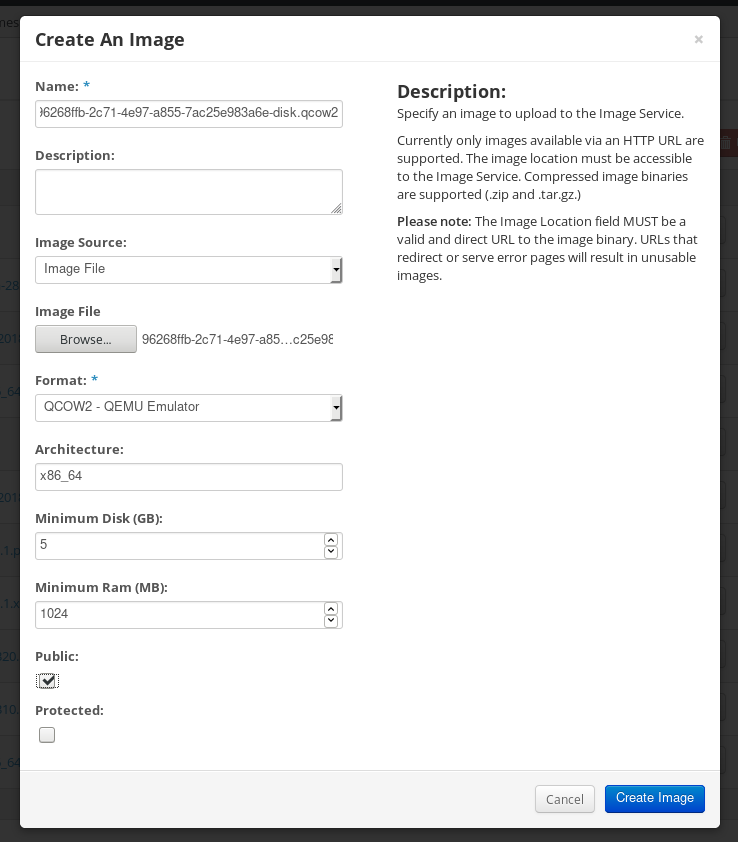
On the left menu, select the
Projecttab.-
From the
Computemenu, selectInstances. Click the button.
The
Launch Instancewizard opens.-
On the
Detailspage, enter a name for the instance. Click . -
On the
Sourcepage, select the name of the image you uploaded. Click . On the
Flavorpage, select the machine resources that best fit your needs. Click .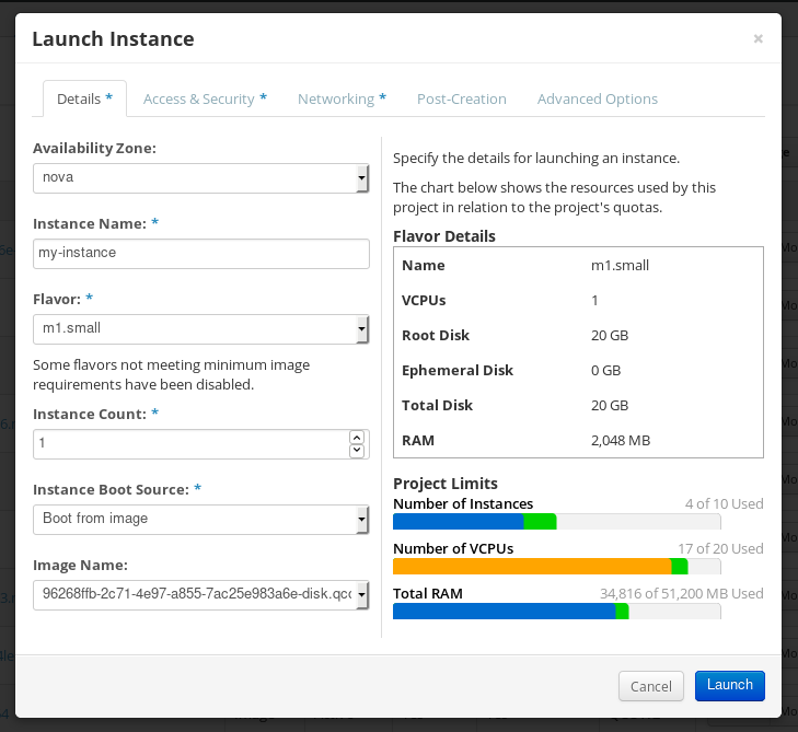
-
From the
-
You can run the image instance using any mechanism (CLI or OpenStack web UI) from the image. Use your private key via SSH to access the resulting instance. Log in as
cloud-user.
9.5.6. Preparing and uploading customized RHEL images to the Alibaba Cloud
You can upload a customized .ami images that you created by using RHEL image builder to the Alibaba Cloud.
9.5.6.1. Preparing to upload customized RHEL images to Alibaba Cloud
To deploy a customized RHEL image to the Alibaba Cloud, first you need to verify the customized image. The image needs a specific configuration to boot successfully, because Alibaba Cloud requests the custom images to meet certain requirements before you use it.
RHEL image builder generates images that conform to Alibaba’s requirements. However, Red Hat recommends also using the Alibaba image_check tool to verify the format compliance of your image.
Prerequisites
- You must have created an Alibaba image by using RHEL image builder.
Procedure
- Connect to the system containing the image that you want to check by using the Alibaba image_check tool.
Download the image_check tool:
$ curl -O https://docs-aliyun.cn-hangzhou.oss.aliyun-inc.com/assets/attach/73848/cn_zh/1557459863884/image_checkChange the file permission of the image compliance tool:
# chmod +x image_checkRun the command to start the image compliance tool checkup:
# ./image_checkThe tool verifies the system configuration and generates a report that is displayed on your screen. The image_check tool saves this report in the same folder where the image compliance tool is running.
Troubleshooting
If any of the Detection Items fail, follow the instructions in the terminal to correct it.
9.5.6.2. Uploading customized RHEL images to Alibaba
You can upload a customized AMI image you created by using RHEL image builder to the Object Storage Service (OSS).
Prerequisites
- Your system is set up for uploading Alibaba images. See Preparing for uploading images to Alibaba.
-
You have created an
amiimage by using RHEL image builder. - You have a bucket. See Creating a bucket.
- You have an active Alibaba Account.
- You activated OSS.
Procedure
- Log in to the OSS console.
- In the Bucket menu on the left, select the bucket to which you want to upload an image.
- In the upper right menu, click the Files tab.
Click . A dialog window opens on the right side. Configure the following:
- Upload To: Choose to upload the file to the Current directory or to a Specified directory.
- File ACL: Choose the type of permission of the uploaded file.
- Click .
- Select the image you want to upload to the OSS Console..
- Click .
9.5.6.3. Importing images to Alibaba Cloud
To import a customized Alibaba RHEL image that you created by using RHEL image builder to the Elastic Compute Service (ECS), follow the steps:
Prerequisites
- Your system is set up for uploading Alibaba images. See Preparing for uploading images to Alibaba.
-
You have created an
amiimage by using RHEL image builder. - You have a bucket. See Creating a bucket.
- You have an active Alibaba Account.
- You activated OSS.
- You have uploaded the image to Object Storage Service (OSS). See Uploading images to Alibaba.
Procedure
Log in to the ECS console.
- On the left-side menu, click .
- On the upper right side, click . A dialog window opens.
Confirm that you have set up the correct region where the image is located. Enter the following information:
-
OSS Object Address: See how to obtain OSS Object Address. -
Image Name -
Operating System -
System Disk Size -
System Architecture -
Platform: Red Hat
-
Optional: Provide the following details:
-
Image Format:qcow2orami, depending on the uploaded image format. -
Image Description Add Images of Data DisksThe address can be determined in the OSS management console. After selecting the required bucket in the left menu:
-
-
Select
Filessection. Click the Details link on the right for the appropriate image.
A window appears on the right side of the screen, showing image details. The
OSSobject address is in theURLbox.Click .
NoteThe importing process time can vary depending on the image size.
The customized image is imported to the ECS Console.
9.5.6.4. Creating an instance of a customized RHEL image using Alibaba Cloud
You can create instances of a customized RHEL image by using the Alibaba ECS Console.
Prerequisites
- You have activated OSS and uploaded your custom image.
- You have successfully imported your image to ECS Console. See Importing images to Alibaba.
Procedure
- Log in to the ECS console.
- On the left-side menu, select Instances.
- In the upper-right corner, click Create Instance. You are redirected to a new window.
- Complete all the required information. See Creating an instance by using the wizard for more details.
Click Create Instance and confirm the order.
NoteYou can see the option Create Order instead of Create Instance, depending on your subscription.
As a result, you have an active instance ready for deployment from the Alibaba ECS Console.
Chapter 10. Performing an automated installation using Kickstart
10.1. Automated installation workflow
Kickstart installations can be performed using a local DVD, a local disk, or a NFS, FTP, HTTP, or HTTPS server. This section provides a high level overview of Kickstart usage.
- Create a Kickstart file. You can write it by hand, copy a Kickstart file saved after a manual installation, or use an online generator tool to create the file, and edit it afterward.
- Make the Kickstart file available to the installation program on removable media, a disk or a network location using an HTTP(S), FTP, or NFS server.
- Create the boot medium which will be used to begin the installation.
- Make the installation source available to the installation program.
- Start the installation using the boot medium and the Kickstart file. If the Kickstart file contains all mandatory commands and sections, the installation finishes automatically. If one or more of these mandatory parts are missing, or if an error occurs, the installation requires manual intervention to finish.
10.2. Creating Kickstart files
You can create a Kickstart file using the following methods:
- Use the online Kickstart configuration tool.
- Copy the Kickstart file created as a result of a manual installation.
- Write the entire Kickstart file manually.
Convert the Red Hat Enterprise Linux 7 Kickstart file for Red Hat Enterprise Linux 8 installation.
For more information about the conversion tool, see Kickstart generator lab.
- In case of virtual and cloud environment, create a custom system image, using Image Builder.
Some highly specific installation options can be configured only by manual editing of the Kickstart file.
10.2.1. Creating a Kickstart file with the Kickstart configuration tool
Users with a Red Hat Customer Portal account can use the Kickstart Generator tool in the Customer Portal Labs to generate Kickstart files online. This tool will walk you through the basic configuration and enables you to download the resulting Kickstart file.
Prerequisites
- You have a Red Hat Customer Portal account and an active Red Hat subscription.
Procedure
- Open the Kickstart generator lab information page at https://access.redhat.com/labsinfo/kickstartconfig.
- Click the Go to Application button to the left of heading and wait for the next page to load.
- Select Red Hat Enterprise Linux 8 in the drop-down menu and wait for the page to update.
Describe the system to be installed using the fields in the form.
You can use the links on the left side of the form to quickly navigate between sections of the form.
To download the generated Kickstart file, click the red Download button at the top of the page.
Your web browser saves the file.
Install the pykickstart package.
# yum install pykickstartRun
ksvalidatoron your Kickstart file.$ ksvalidator -v RHEL8 /path/to/kickstart.ksReplace /path/to/kickstart.ks with the path to the Kickstart file you want to verify.
The validation tool cannot guarantee the installation will be successful. It ensures only that the syntax is correct and that the file does not include deprecated options. It does not attempt to validate the
%pre,%postand%packagessections of the Kickstart file.
10.2.2. Creating a Kickstart file by performing a manual installation
The recommended approach to creating Kickstart files is to use the file created by a manual installation of Red Hat Enterprise Linux. After an installation completes, all choices made during the installation are saved into a Kickstart file named anaconda-ks.cfg, located in the /root/ directory on the installed system. You can use this file to reproduce the installation in the same way as before. Alternatively, copy this file, make any changes you need, and use the resulting configuration file for further installations.
Procedure
Install RHEL. For more details, see Interactively installing RHEL from installation media.
During the installation, create a user with administrator privileges.
- Finish the installation and reboot into the installed system.
- Log into the system with the administrator account.
Copy the file
/root/anaconda-ks.cfgto a location of your choice. The file contains information about users and passwords.To display the file contents in terminal:
# cat /root/anaconda-ks.cfgYou can copy the output and save to another file of your choice.
- To copy the file to another location, use the file manager. Remember to change permissions on the copy, so that the file can be read by non-root users.
Install the pykickstart package.
# yum install pykickstartRun
ksvalidatoron your Kickstart file.$ ksvalidator -v RHEL8 /path/to/kickstart.ksReplace /path/to/kickstart.ks with the path to the Kickstart file you want to verify.
The validation tool cannot guarantee the installation will be successful. It ensures only that the syntax is correct and that the file does not include deprecated options. It does not attempt to validate the %pre, %post and %packages sections of the Kickstart file.
10.2.3. Converting a Kickstart file from previous RHEL installation
You can use the Kickstart Converter tool to convert a RHEL 7 Kickstart file for use in a RHEL 8 or 9 installation or convert a RHEL 8 Kickstart file for use it in RHEL 9. For more information about the tool and how to use it to convert a RHEL Kickstart file, see https://access.redhat.com/labs/kickstartconvert/.
Procedure
After you prepare your kickstart file, install the pykickstart package.
# yum install pykickstartRun
ksvalidatoron your Kickstart file.$ ksvalidator -v RHEL8 /path/to/kickstart.ksReplace /path/to/kickstart.ks with the path to the Kickstart file you want to verify.
The validation tool cannot guarantee the installation will be successful. It ensures only that the syntax is correct and that the file does not include deprecated options. It does not attempt to validate the %pre, %post and %packages sections of the Kickstart file.
10.2.4. Creating a custom image using Image Builder
You can use Red Hat Image Builder to create a customized system image for virtual and cloud deployments.
For more information about creating customized images, using Image Builder, see the Composing a customized RHEL system image document.
10.3. Adding the Kickstart file to a UEFI HTTP or PXE installation source
After your Kickstart file is ready, you can make it available for the installation on the destination system.
10.3.1. Ports for network-based installation
The following table lists the ports that must be open on the server for providing the files for each type of network-based installation.
| Protocol used | Ports to open |
|---|---|
| HTTP | 80 |
| HTTPS | 443 |
| FTP | 21 |
| NFS | 2049, 111, 20048 |
| TFTP | 69 |
10.3.2. Sharing the installation files on an NFS server
You can store the Kickstart script file on an NFS server. Storing it on an NFS server enables you to install multiple systems from a single source without having to use physical media for the Kickstart file.
Prerequisites
- You have an administrator-level access to a server with Red Hat Enterprise Linux 8 on the local network.
- The system to be installed can connect to the server.
- The firewall on the server allows connections from the system you are installing to.
Ensure that you use different paths in inst.ks and inst.repo. When using NFS to host the Kickstart, you cannot use the same nfs share to host the installation source.
Procedure
Install the
nfs-utilspackage by running the following command as root:# yum install nfs-utils- Copy the Kickstart file to a directory on the NFS server.
Open the
/etc/exportsfile using a text editor and add a line with the following syntax:/exported_directory/ clientsReplace /exported_directory/ with the full path to the directory holding the Kickstart file. Instead of clients, use the host name or IP address of the computer that is to be installed from this NFS server, the subnetwork from which all computers are to have access the ISO image, or the asterisk sign (
*) if you want to allow any computer with network access to the NFS server to use the ISO image. See the exports(5) man page for detailed information about the format of this field. A basic configuration that makes the/rhel8-install/directory available as read-only to all clients is:/rhel8-install *-
Save the
/etc/exportsfile and exit the text editor. Start the nfs service:
# systemctl start nfs-server.serviceIf the service was running before you changed the
/etc/exportsfile, enter the following command, in order for the running NFS server to reload its configuration:# systemctl reload nfs-server.serviceThe Kickstart file is now accessible over NFS and ready to be used for installation.
When specifying the Kickstart source, use nfs: as the protocol, the server’s host name or IP address, the colon sign (:), and the path inside directory holding the file. For example, if the server’s host name is myserver.example.com and you have saved the file in /rhel8-install/my-ks.cfg, specify inst.ks=nfs:myserver.example.com:/rhel8-install/my-ks.cfg as the installation source boot option.
10.3.3. Sharing the installation files on an HTTP or HTTPS server
You can store the Kickstart script file on an HTTP or HTTPS server. Storing the Kickstart file on an HTTP or HTTPS server enables you to install multiple systems from a single source without having to use physical media for the Kickstart file.
Prerequisites
- You have an administrator-level access to a server with Red Hat Enterprise Linux 8 on the local network.
- The system to be installed can connect to the server.
- The firewall on the server allows connections from the system you are installing to.
Procedure
To store the Kickstart file on an HTTP, install the
httpdpackage:# yum install httpdTo store the Kickstart file on an HTTPS, install
httpdandmod_sslpackages:# yum install httpd mod_sslWarningIf your Apache web server configuration enables SSL security, verify that you only enable the TLSv1 protocol, and disable SSLv2 and SSLv3. This is due to the POODLE SSL vulnerability (CVE-2014-3566). For more information, see the Red Hat Knowledgebase solution Resolution for POODLE SSLv3.0 vulnerability.
ImportantIf you use an HTTPS server with a self-signed certificate, you must boot the installation program with the
inst.noverifyssloption.-
Copy the Kickstart file to the HTTP(S) server into a subdirectory of the
/var/www/html/directory. Start the httpd service:
# systemctl start httpd.serviceThe Kickstart file is now accessible and ready to be used for installation.
When specifying the location of the Kickstart file, use
http://orhttps://as the protocol, the server’s host name or IP address, and the path of the Kickstart file, relative to the HTTP server root. For example, if you are using HTTP, the server’s host name ismyserver.example.com, and you have copied the Kickstart file as/var/www/html/rhel8-install/my-ks.cfg, specifyhttp://myserver.example.com/rhel8-install/my-ks.cfgas the file location.
10.3.4. Sharing the installation files on an FTP server
You can store the Kickstart script file on an FTP server. Storing the script on an FTP server enables you to install multiple systems from a single source without having to use physical media for the Kickstart file.
Prerequisites
- You have an administrator-level access to a server with Red Hat Enterprise Linux 8 on the local network.
- The system to be installed can connect to the server.
- The firewall on the server allows connections from the system you are installing to.
Procedure
Install the
vsftpdpackage by running the following command as root:# yum install vsftpdOpen and edit the
/etc/vsftpd/vsftpd.confconfiguration file in a text editor.-
Change the line
anonymous_enable=NOtoanonymous_enable=YES -
Change the line
write_enable=YEStowrite_enable=NO. Add lines
pasv_min_port=min_portandpasv_max_port=max_port. Replacemin_portandmax_portwith the port number range used by FTP server in passive mode, for example,10021and10031.This step can be necessary in network environments featuring various firewall/NAT setups.
Optional: add custom changes to your configuration. For available options, see the vsftpd.conf(5) man page. This procedure assumes that default options are used.
WarningIf you configured SSL/TLS security in your
vsftpd.conffile, ensure that you enable only the TLSv1 protocol, and disable SSLv2 and SSLv3. This is due to the POODLE SSL vulnerability (CVE-2014-3566). For more information, see the Red Hat Knowledgebase solution Resolution for POODLE SSLv3.0 vulnerability.
-
Change the line
Configure the server firewall.
Enable the firewall:
# systemctl enable firewalld # systemctl start firewalldEnable in your firewall the FTP port and port range from previous step:
# firewall-cmd --add-port min_port-max_port/tcp --permanent # firewall-cmd --add-service ftp --permanent # firewall-cmd --reloadReplace min_port-max_port with the port numbers you entered into the
/etc/vsftpd/vsftpd.confconfiguration file.
-
Copy the Kickstart file to the FTP server into the
/var/ftp/directory or its subdirectory. Make sure that the correct SELinux context and access mode is set on the file:
# restorecon -r /var/ftp/your-kickstart-file.ks # chmod 444 /var/ftp/your-kickstart-file.ksStart the
vsftpdservice:# systemctl start vsftpd.serviceIf the service was running before you changed the
/etc/vsftpd/vsftpd.conffile, restart the service to load the edited file:# systemctl restart vsftpd.serviceEnable the
vsftpdservice to start during the boot process:# systemctl enable vsftpdThe Kickstart file is now accessible and ready to be used for installations by systems on the same network.
NoteWhen configuring the installation source, use
ftp://as the protocol, the server’s host name or IP address, and the path of the Kickstart file, relative to the FTP server root. For example, if the server’s host name ismyserver.example.comand you have copied the file to/var/ftp/my-ks.cfg, specifyftp://myserver.example.com/my-ks.cfgas the installation source.
10.4. Semi-automated installations: Making Kickstart files available to the RHEL installer
After your Kickstart file is ready, you can make it available to for installation on the destination system.
10.4.1. Sharing the installation files on a local volume
This procedure describes how to store the Kickstart script file on a volume on the system to be installed. This method enables you to bypass the need for another system.
Prerequisites
- You have a drive that can be moved to the machine to be installed, such as a USB stick.
-
The drive contains a partition that can be read by the installation program. The supported types are
ext2,ext3,ext4,xfs, andfat. - The drive is connected to the system and its volumes are mounted.
Procedure
List volume information and note the UUID of the volume to which you want to copy the Kickstart file.
# lsblk -l -p -o name,rm,ro,hotplug,size,type,mountpoint,uuid- Navigate to the file system on the volume.
- Copy the Kickstart file to this file system.
-
Make a note of the string to use later with the
inst.ks=option. This string is in the formhd:UUID=volume-UUID:path/to/kickstart-file.cfg. Note that the path is relative to the file system root, not to the/root of file system hierarchy. Replace volume-UUID with the UUID you noted earlier. Unmount all drive volumes:
# umount /dev/xyz ...Add all the volumes to the command, separated by spaces.
10.4.2. Sharing the installation files on a local volume for automatic loading
A specially named Kickstart file can be present in the root of a specially named volume on the system to be installed. This lets you bypass the need for another system, and makes the installation program load the file automatically.
Prerequisites
- You have a drive that can be moved to the machine to be installed, such as a USB stick.
-
The drive contains a partition that can be read by the installation program. The supported types are
ext2,ext3,ext4,xfs, andfat. - The drive is connected to the system and its volumes are mounted.
Procedure
List volume information to which you want to copy the Kickstart file.
# lsblk -l -p- Navigate to the file system on the volume.
- Copy the Kickstart file into the root of this file system.
-
Rename the Kickstart file to
ks.cfg. Rename the volume as
OEMDRV:For
ext2,ext3, andext4file systems:# e2label /dev/xyz OEMDRVFor the XFS file system:
# xfs_admin -L OEMDRV /dev/xyz
Replace /dev/xyz with the path to the volume’s block device.
Unmount all drive volumes:
# umount /dev/xyz ...Add all the volumes to the command, separated by spaces.
10.5. Starting Kickstart installations
You can start Kickstart installations in multiple ways:
- Automatically by editing the boot options in PXE boot.
- Automatically by providing the file on a volume with specific name.
You can register RHEL using the Red Hat Content Delivery Network (CDN). CDN is a geographically distributed series of web servers. These servers provide, for example, packages and updates to RHEL hosts with a valid subscription.
During the installation, registering and installing RHEL from the CDN offers following benefits:
- Utilizing the latest packages for an up-to-date system immediately after installation and
- Integrated support for connecting to Red Hat Insights and enabling System Purpose.
10.5.1. Starting a Kickstart installation automatically using PXE
AMD64, Intel 64, and 64-bit ARM systems and IBM Power Systems servers have the ability to boot using a PXE server. When you configure the PXE server, you can add the boot option into the boot loader configuration file, which in turn lets you start the installation automatically. Using this approach, it is possible to automate the installation completely, including the boot process.
This procedure is intended as a general reference; detailed steps differ based on your system’s architecture, and not all options are available on all architectures (for example, you cannot use PXE boot on 64-bit IBM Z).
Prerequisites
- You have a Kickstart file ready in a location accessible from the system to be installed.
- You have a PXE server that can be used to boot the system and begin the installation.
Procedure
Open the boot loader configuration file on your PXE server, and add the
inst.ks=boot option to the appropriate line. The name of the file and its syntax depends on your system’s architecture and hardware:On AMD64 and Intel 64 systems with BIOS, the file name can be either default or based on your system’s IP address. In this case, add the
inst.ks=option to the append line in the installation entry. A sample append line in the configuration file looks similar to the following:append initrd=initrd.img inst.ks=http://10.32.5.1/mnt/archive/RHEL-8/8.x/x86_64/kickstarts/ks.cfgOn systems using the GRUB boot loader (AMD64, Intel 64, and 64-bit ARM systems with UEFI firmware and IBM Power Systems servers), the file name is
grub.cfg. In this file, append theinst.ks=option to the kernel line in the installation entry. A sample kernel line in the configuration file will look similar to the following:kernel vmlinuz inst.ks=http://10.32.5.1/mnt/archive/RHEL-8/8.x/x86_64/kickstarts/ks.cfg
Boot the installation from the network server.
The installation begins now, using the installation options specified in the Kickstart file. If the Kickstart file is valid and contains all required commands, the installation is completely automated.
If you have installed a Red Hat Enterprise Linux Beta release, on systems having UEFI Secure Boot enabled, then add the Beta public key to the system’s Machine Owner Key (MOK) list.
10.5.2. Starting a Kickstart installation automatically using a local volume
You can start a Kickstart installation by putting a Kickstart file with a specific name on a specifically labelled storage volume.
Prerequisites
-
You have a volume prepared with label
OEMDRVand the Kickstart file present in its root asks.cfg. - A drive containing this volume is available on the system as the installation program boots.
Procedure
- Boot the system using a local media (a CD, DVD, or a USB flash drive).
At the boot prompt, specify the required boot options.
-
If a required repository is in a network location, you may need to configure the network using the
ip=option. The installer tries to configure all network devices using the DHCP protocol by default without this option. In order to access a software source from which necessary packages will be installed, you may need to add the
inst.repo=option. If you do not specify this option, you must specify the installation source in the Kickstart file.For more information about installation sources, see Kickstart commands for installation program configuration and flow control.
-
If a required repository is in a network location, you may need to configure the network using the
Start the installation by confirming your added boot options.
The installation begins now, and the Kickstart file is automatically detected and used to start an automated Kickstart installation.
If you have installed a Red Hat Enterprise Linux Beta release, on systems having UEFI Secure Boot enabled, then add the Beta public key to the system’s Machine Owner Key (MOK) list. For more information about UEFI Secure Boot and Red Hat Enterprise Linux Beta releases, see the UEFI Secure Boot and Beta release requirements.
10.5.3. Booting the installation on IBM Z to install RHEL in an LPAR
10.5.3.1. Booting the RHEL installation from an SFTP, FTPS, or FTP server to install in an IBM Z LPAR
You can install RHEL into an LPAR by using an SFTP, FTPS, or FTP server.
Procedure
- Log in on the IBM Z Hardware Management Console (HMC) or the Support Element (SE) as a user with sufficient privileges to install a new operating system to an LPAR.
- On the Systems tab, select the mainframe you want to work with, then on the Partitions tab select the LPAR to which you wish to install.
- At the bottom of the screen, under Daily, find Operating System Messages. Double-click Operating System Messages to show the text console on which Linux boot messages will appear.
- Double-click Load from Removable Media or Server.
In the dialog box that follows, select SFTP/FTPS/FTP Server, and enter the following information:
- Host Computer - Host name or IP address of the FTP server you want to install from, for example ftp.redhat.com
- User ID - Your user name on the FTP server. Or, specify anonymous.
- Password - Your password. Use your email address if you are logging in as anonymous.
- File location (optional) - Directory on the FTP server holding the Red Hat Enterprise Linux for IBM Z, for example /rhel/s390x/.
- Click Continue.
- In the dialog that follows, keep the default selection of generic.ins and click Continue.
10.5.3.2. Booting the RHEL installation from a prepared DASD to install in an IBM Z LPAR
Use this procedure when installing Red Hat Enterprise Linux into an LPAR using an already prepared DASD.
Procedure
- Log in on the IBM Z Hardware Management Console (HMC) or the Support Element (SE) as a user with sufficient privileges to install a new operating system to an LPAR.
- On the Systems tab, select the mainframe you want to work with, then on the Partitions tab select the LPAR to which you wish to install.
- At the bottom of the screen, under Daily, find Operating System Messages. Double-click Operating System Messages to show the text console on which Linux boot messages will appear.
- Double-click Load.
- In the dialog box that follows, select Normal as the Load type.
- As Load address, fill in the device number of the DASD.
- Click the OK button.
10.5.3.3. Booting the RHEL installation from an FCP-attached SCSI disk to install in an IBM Z LPAR
Use this procedure when installing Red Hat Enterprise Linux into an LPAR using an already prepared FCP attached SCSI disk.
Procedure
- Log in on the IBM Z Hardware Management Console (HMC) or the Support Element (SE) as a user with sufficient privileges to install a new operating system to an LPAR.
- On the Systems tab, select the mainframe you want to work with, then on the Partitions tab select the LPAR to which you wish to install.
- At the bottom of the screen, under Daily, find Operating System Messages. Double-click Operating System Messages to show the text console on which Linux boot messages will appear.
- Double-click Load.
- In the dialog box that follows, select SCSI as the Load type.
- As Load address, fill in the device number of the FCP channel connected with the SCSI disk.
- As World wide port name, fill in the WWPN of the storage system containing the disk as a 16-digit hexadecimal number.
- As Logical unit number, fill in the LUN of the disk as a 16-digit hexadecimal number.
- Leave the Boot record logical block address as 0 and the Operating system specific load parameters empty.
- Click the OK button.
10.5.3.4. Booting the RHEL installation from an FCP-attached SCSI DVD drive to install in an IBM Z LPAR
This requires a SCSI DVD drive attached to an FCP-to-SCSI bridge which is in turn connected to an FCP adapter in your IBM Z machine. The FCP adapter must be configured and available in your LPAR.
Procedure
- Log in on the IBM Z Hardware Management Console (HMC) or the Support Element (SE) as a user with sufficient privileges to install a new operating system to an LPAR.
- On the Systems tab, select the mainframe you want to work with, then on the Partitions tab select the LPAR to which you wish to install.
- At the bottom of the screen, under Daily, find the Operating System Messages. Double-click Operating System Messages to show the text console on which Linux boot messages will appear.
- Insert your Red Hat Enterprise Linux for 64-bit IBM Z DVD into the DVD drive.
- Double-click Load.
- In the dialog box that follows, select SCSI as the Load type.
- As Load address, fill in the device number of the FCP channel connected with the FCP-to-SCSI bridge.
- As World wide port name, fill in the WWPN of the FCP-to-SCSI bridge as a 16-digit hexadecimal number.
- As Logical unit number, fill in the LUN of the DVD drive as a 16-digit hexadecimal number.
- As Boot program selector, fill in the number 1 to select the boot entry on the Red Hat Enterprise Linux for 64-bit IBM Z DVD.
- Leave the Boot record logical block address as 0 and the Operating system specific load parameters empty.
- Click the OK button.
10.5.4. Booting the installation on IBM Z to install RHEL in z/VM
When installing under z/VM, you can boot from:
- The z/VM virtual reader
- A DASD or an FCP-attached SCSI disk prepared with the zipl boot loader
- An FCP-attached SCSI DVD drive
10.5.4.1. Booting the RHEL installation by using the z/VM Reader
You can boot from the z/VM reader.
Procedure
If necessary, add the device containing the z/VM TCP/IP tools to your CMS disk list. For example:
cp link tcpmaint 592 592 acc 592 fmReplace fm with any
FILEMODEletter.For a connection to an FTPS server, enter:
ftp <host> (secureWhere
hostis the host name or IP address of the FTP server that hosts the boot images (kernel.imgandinitrd.img).Log in and execute the following commands. Use the
(reploption if you are overwriting existingkernel.img,initrd.img,generic.prm, orredhat.execfiles:cd /location/of/install-tree/images/ ascii get generic.prm (repl get redhat.exec (repl locsite fix 80 binary get kernel.img (repl get initrd.img (repl quitOptional: Check whether the files were transferred correctly by using the CMS command
filelistto show the received files and their format. It is important thatkernel.imgandinitrd.imghave a fixed record length format denoted by F in the Format column and a record length of 80 in the Lrecl column. For example:VMUSER FILELIST A0 V 169 Trunc=169 Size=6 Line=1 Col=1 Alt=0 Cmd Filename Filetype Fm Format Lrecl Records Blocks Date Time REDHAT EXEC B1 V 22 1 1 4/15/10 9:30:40 GENERIC PRM B1 V 44 1 1 4/15/10 9:30:32 INITRD IMG B1 F 80 118545 2316 4/15/10 9:30:25 KERNEL IMG B1 F 80 74541 912 4/15/10 9:30:17Press PF3 to quit filelist and return to the CMS prompt.
Customize boot parameters in
generic.prmas necessary. For details, see Customizing boot parameters.Another way to configure storage and network devices is by using a CMS configuration file. In such a case, add the
CMSDASD=andCMSCONFFILE=parameters togeneric.prm.Finally, execute the REXX script redhat.exec to boot the installation program:
redhat
10.5.4.2. Booting the RHEL installation by using a prepared DASD
Perform the following steps to use a Prepared DASD:
Procedure
Boot from the prepared DASD and select the zipl boot menu entry referring to the Red Hat Enterprise Linux installation program. Use a command of the following form:
cp ipl DASD_device_number loadparm boot_entry_numberReplace DASD_device_number with the device number of the boot device, and boot_entry_number with the zipl configuration menu for this device. For example:
cp ipl eb1c loadparm 0
10.5.4.3. Booting the RHEL installation by using a prepared FCP attached SCSI Disk
Perform the following steps to boot from a prepared FCP-attached SCSI disk:
Procedure
Configure the SCSI boot loader of z/VM to access the prepared SCSI disk in the FCP Storage Area Network. Select the prepared zipl boot menu entry referring to the Red Hat Enterprise Linux installation program. Use a command of the following form:
cp set loaddev portname WWPN lun LUN bootprog boot_entry_numberReplace WWPN with the World Wide Port Name of the storage system and LUN with the Logical Unit Number of the disk. The 16-digit hexadecimal numbers must be split into two pairs of eight digits each. For example:
cp set loaddev portname 50050763 050b073d lun 40204011 00000000 bootprog 0Optional: Confirm your settings with the command:
query loaddevBoot the FCP device connected with the storage system containing the disk with the following command:
cp ipl FCP_deviceFor example:
cp ipl fc00
10.5.4.4. Booting the RHEL installation by using an FCP-attached SCSI DVD Drive
Perform the following steps to use a Prepared FCP attached SCSI DVD Drive:
Prerequisites
- This requires a SCSI DVD drive attached to an FCP-to-SCSI bridge which is in turn connected to an FCP adapter in your 64-bit IBM Z. The FCP adapter must be configured and available under z/VM.
Procedure
- Insert your Red Hat Enterprise Linux for 64-bit IBM Z DVD into the DVD drive.
Configure the SCSI boot loader of z/VM to access the DVD drive in the FCP Storage Area Network and specify
1for the boot entry on the Red Hat Enterprise Linux for 64-bit IBM Z DVD. Use a command of the following form:cp set loaddev portname WWPN lun FCP_LUN bootprog 1Replace WWPN with the WWPN of the FCP-to-SCSI bridge and FCP_LUN with the LUN of the DVD drive. The 16-digit hexadecimal numbers must be split into two pairs of eight characters each. For example:
cp set loaddev portname 20010060 eb1c0103 lun 00010000 00000000 bootprog 1Optional: Confirm your settings with the command:
cp query loaddevIPL on the FCP device connected with the FCP-to-SCSI bridge.
cp ipl FCP_deviceFor example:
cp ipl fc00
10.5.5. Consoles and logging during installation
The Red Hat Enterprise Linux installer uses the tmux terminal multiplexer to display and control several windows in addition to the main interface. Each of these windows serve a different purpose; they display several different logs, which can be used to troubleshoot issues during the installation process. One of the windows provides an interactive shell prompt with root privileges, unless this prompt was specifically disabled using a boot option or a Kickstart command.
The terminal multiplexer is running in virtual console 1. To switch from the actual installation environment to tmux, press Ctrl+Alt+F1. To go back to the main installation interface which runs in virtual console 6, press Ctrl+Alt+F6. During the text mode installation, start in virtual console 1 (tmux), and switching to console 6 will open a shell prompt instead of a graphical interface.
The console running tmux has five available windows; their contents are described in the following table, along with keyboard shortcuts. Note that the keyboard shortcuts are two-part: first press Ctrl+b, then release both keys, and press the number key for the window you want to use.
You can also use Ctrl+b n, Alt+ Tab, and Ctrl+b p to switch to the next or previous tmux window, respectively.
| Shortcut | Contents |
|---|---|
| Ctrl+b 1 | Main installation program window. Contains text-based prompts (during text mode installation or if you use VNC direct mode), and also some debugging information. |
| Ctrl+b 2 |
Interactive shell prompt with |
| Ctrl+b 3 |
Installation log; displays messages stored in |
| Ctrl+b 4 |
Storage log; displays messages related to storage devices and configuration, stored in |
| Ctrl+b 5 |
Program log; displays messages from utilities executed during the installation process, stored in |
Chapter 11. Advanced configuration options
11.1. Configuring System Purpose
You use System Purpose to record the intended use of a Red Hat Enterprise Linux 8 system. Setting System Purpose enables the entitlement server to auto-attach the most appropriate subscription. This section describes how to configure System Purpose using Kickstart.
Benefits include:
- In-depth system-level information for system administrators and business operations.
- Reduced overhead when determining why a system was procured and its intended purpose.
- Improved customer experience of Subscription Manager auto-attach as well as automated discovery and reconciliation of system usage.
11.1.1. Overview
You can enter System Purpose data in one of the following ways:
- During image creation
- During a GUI installation when using the Connect to Red Hat screen to register your system and attach your Red Hat subscription
-
During a Kickstart installation when using the
syspurpose Kickstartcommand -
After installation using the
syspurposecommand-line (CLI) tool
To record the intended purpose of your system, you can configure the following components of System Purpose. The selected values are used by the entitlement server upon registration to attach the most suitable subscription for your system.
- Role
- Red Hat Enterprise Linux Server
- Red Hat Enterprise Linux Workstation
- Red Hat Enterprise Linux Compute Node
- Service Level Agreement
- Premium
- Standard
- Self-Support
- Usage
- Production
- Development/Test
- Disaster Recovery
11.1.2. Configuring System Purpose in a Kickstart file
Follow the steps in this procedure to configure System Purpose during the installation. To do so, use the syspurpose Kickstart command in the Kickstart configuration file.
Even though System Purpose is an optional feature of the Red Hat Enterprise Linux installation program, we strongly recommend that you configure System Purpose to auto-attach the most appropriate subscription.
You can also enable System Purpose after the installation is complete. To do so use the syspurpose command-line tool. The syspurpose tool commands are different from the syspurpose Kickstart commands.
The following actions are available for the syspurpose Kickstart command:
- role
Set the intended role of the system. This action uses the following format:
syspurpose --role=The assigned role can be:
-
Red Hat Enterprise Linux Server -
Red Hat Enterprise Linux Workstation -
Red Hat Enterprise Linux Compute Node
-
- SLA
Set the intended SLA of the system. This action uses the following format:
syspurpose --sla=The assigned sla can be:
-
Premium -
Standard -
Self-Support
-
- usage
Set the intended usage of the system. This action uses the following format:
syspurpose --usage=The assigned usage can be:
-
Production -
Development/Test -
Disaster Recovery
-
- addon
Any additional layered products or features. To add multiple items specify
--addonmultiple times, once per layered product/feature. This action uses the following format:syspurpose --addon=
11.2. Preparing a UEFI HTTP installation source
As an administrator of a server on a local network, you can configure an HTTP server to enable HTTP boot and network installation for other systems on your network.
11.2.1. Network install overview
A network installation allows you to install Red Hat Enterprise Linux to a system that has access to an installation server. At a minimum, two systems are required for a network installation:
- Server
- A system running a DHCP server, an HTTP, HTTPS, FTP, or NFS server, and in the PXE boot case, a TFTP server. Although each server can run on a different physical system, the procedures in this section assume a single system is running all servers.
- Client
- The system to which you are installing Red Hat Enterprise Linux. Once installation starts, the client queries the DHCP server, receives the boot files from the HTTP or TFTP server, and downloads the installation image from the HTTP, HTTPS, FTP or NFS server. Unlike other installation methods, the client does not require any physical boot media for the installation to start.
To boot a client from the network, enable network boot in the firmware or in a quick boot menu on the client. On some hardware, the option to boot from a network might be disabled, or not available.
The workflow steps to prepare to install Red Hat Enterprise Linux from a network using HTTP or PXE are as follows:
Procedure
- Export the installation ISO image or the installation tree to an NFS, HTTPS, HTTP, or FTP server.
- Configure the HTTP or TFTP server and DHCP server, and start the HTTP or TFTP service on the server.
- Boot the client and start the installation.
You can choose between the following network boot protocols:
- HTTP
- Red Hat recommends using HTTP boot if your client UEFI supports it. HTTP boot is usually more reliable.
- PXE (TFTP)
- PXE boot is more widely supported by client systems, but sending the boot files over this protocol might be slow and result in timeout failures.
11.2.2. Configuring the DHCPv4 server for network boot
Enable the DHCP version 4 (DHCPv4) service on your server, so that it can provide network boot functionality.
Prerequisites
You are preparing network installation over the IPv4 protocol.
For IPv6, see Configuring the DHCPv6 server for network boot instead.
Find the network addresses of the server.
In the following examples, the server has a network card with this configuration:
- IPv4 address
- 192.168.124.2/24
- IPv4 gateway
- 192.168.124.1
Procedure
Install the DHCP server:
yum install dhcp-serverSet up a DHCPv4 server. Enter the following configuration in the
/etc/dhcp/dhcpd.conffile. Replace the addresses to match your network card.option architecture-type code 93 = unsigned integer 16; subnet 192.168.124.0 netmask 255.255.255.0 { option routers 192.168.124.1; option domain-name-servers 192.168.124.1; range 192.168.124.100 192.168.124.200; class "pxeclients" { match if substring (option vendor-class-identifier, 0, 9) = "PXEClient"; next-server 192.168.124.2; if option architecture-type = 00:07 { filename "redhat/EFI/BOOT/BOOTX64.EFI"; } else { filename "pxelinux/pxelinux.0"; } } class "httpclients" { match if substring (option vendor-class-identifier, 0, 10) = "HTTPClient"; option vendor-class-identifier "HTTPClient"; filename "http://192.168.124.2/redhat/EFI/BOOT/BOOTX64.EFI"; } }Start the DHCPv4 service:
# systemctl enable --now dhcpd
11.2.3. Configuring the DHCPv6 server for network boot
Enable the DHCP version 6 (DHCPv4) service on your server, so that it can provide network boot functionality.
Prerequisites
You are preparing network installation over the IPv6 protocol.
For IPv4, see Configuring the DHCPv4 server for network boot instead.
Find the network addresses of the server.
In the following examples, the server has a network card with this configuration:
- IPv6 address
- fd33:eb1b:9b36::2/64
- IPv6 gateway
- fd33:eb1b:9b36::1
Procedure
Install the DHCP server:
yum install dhcp-serverSet up a DHCPv6 server. Enter the following configuration in the
/etc/dhcp/dhcpd6.conffile. Replace the addresses to match your network card.option dhcp6.bootfile-url code 59 = string; option dhcp6.vendor-class code 16 = {integer 32, integer 16, string}; subnet6 fd33:eb1b:9b36::/64 { range6 fd33:eb1b:9b36::64 fd33:eb1b:9b36::c8; class "PXEClient" { match substring (option dhcp6.vendor-class, 6, 9); } subclass "PXEClient" "PXEClient" { option dhcp6.bootfile-url "tftp://[fd33:eb1b:9b36::2]/redhat/EFI/BOOT/BOOTX64.EFI"; } class "HTTPClient" { match substring (option dhcp6.vendor-class, 6, 10); } subclass "HTTPClient" "HTTPClient" { option dhcp6.bootfile-url "http://[fd33:eb1b:9b36::2]/redhat/EFI/BOOT/BOOTX64.EFI"; option dhcp6.vendor-class 0 10 "HTTPClient"; } }Start the DHCPv6 service:
# systemctl enable --now dhcpd6If DHCPv6 packets are dropped by the RP filter in the firewall, check its log. If the log contains the
rpfilter_DROPentry, disable the filter using the following configuration in the/etc/firewalld/firewalld.conffile:IPv6_rpfilter=no
11.2.4. Configuring the HTTP server for HTTP boot
You must install and enable the httpd service on your server so that the server can provide HTTP boot resources on your network.
Prerequisites
Find the network addresses of the server.
In the following examples, the server has a network card with the
192.168.124.2IPv4 address.
Procedure
Install the HTTP server:
# yum install httpdCreate the
/var/www/html/redhat/directory:# mkdir -p /var/www/html/redhat/- Download the RHEL DVD ISO file. See All Red Hat Enterprise Linux Downloads.
Create a mount point for the ISO file:
# mkdir -p /var/www/html/redhat/iso/Mount the ISO file:
# mount -o loop,ro -t iso9660 path-to-RHEL-DVD.iso /var/www/html/redhat/isoCopy the boot loader, kernel, and
initramfsfrom the mounted ISO file into your HTML directory:# cp -r /var/www/html/redhat/iso/images /var/www/html/redhat/ # cp -r /var/www/html/redhat/iso/EFI /var/www/html/redhat/Make the boot loader configuration editable:
# chmod 644 /var/www/html/redhat/EFI/BOOT/grub.cfgEdit the
/var/www/html/redhat/EFI/BOOT/grub.cfgfile and replace its content with the following:set default="1" function load_video { insmod efi_gop insmod efi_uga insmod video_bochs insmod video_cirrus insmod all_video } load_video set gfxpayload=keep insmod gzio insmod part_gpt insmod ext2 set timeout=60 # END /etc/grub.d/00_header # search --no-floppy --set=root -l 'RHEL-9-3-0-BaseOS-x86_64' # BEGIN /etc/grub.d/10_linux # menuentry 'Install Red Hat Enterprise Linux 9.3' --class fedora --class gnu-linux --class gnu --class os { linuxefi ../../images/pxeboot/vmlinuz inst.repo=http://192.168.124.2/redhat/iso quiet initrdefi ../../images/pxeboot/initrd.img } menuentry 'Test this media & install Red Hat Enterprise Linux 9.3' --class fedora --class gnu-linux --class gnu --class os { linuxefi ../../images/pxeboot/vmlinuz inst.repo=http://192.168.124.2/redhat/iso quiet initrdefi ../../images/pxeboot/initrd.img } submenu 'Troubleshooting -->' { menuentry 'Install Red Hat Enterprise Linux 9.3 in text mode' --class fedora --class gnu-linux --class gnu --class os { linuxefi ../../images/pxeboot/vmlinuz inst.repo=http://192.168.124.2/redhat/iso inst.text quiet initrdefi ../../images/pxeboot/initrd.img } menuentry 'Rescue a Red Hat Enterprise Linux system' --class fedora --class gnu-linux --class gnu --class os { linuxefi ../../images/pxeboot/vmlinuz inst.repo=http://192.168.124.2/redhat/iso inst.rescue quiet initrdefi ../../images/pxeboot/initrd.img } }In this file, replace the following strings:
- RHEL-9-3-0-BaseOS-x86_64 and Red Hat Enterprise Linux 9.3
- Edit the version number to match the version of RHEL that you downloaded.
- 192.168.124.2
- Replace with the IP address to your server.
Make the EFI boot file executable:
# chmod 755 /var/www/html/redhat/EFI/BOOT/BOOTX64.EFIOpen ports in the firewall to allow HTTP (80), DHCP (67, 68) and DHCPv6 (546, 547) traffic:
# firewall-cmd --zone public \ --add-port={80/tcp,67/udp,68/udp,546/udp,547/udp}This command enables temporary access until the next server reboot.
-
Optional: To enable permanent access, add the
--permanentoption to the command. Reload firewall rules:
# firewall-cmd --reloadStart the HTTP server:
# systemctl enable --now httpdMake the
htmldirectory and its content readable and executable:# chmod -cR u=rwX,g=rX,o=rX /var/www/htmlRestore the SELinux context of the
htmldirectory:# restorecon -FvvR /var/www/html
Chapter 12. Preparing a PXE installation source
You must configure TFTP and DHCP on a PXE server to enable PXE boot and network installation.
12.1. Network install overview
A network installation allows you to install Red Hat Enterprise Linux to a system that has access to an installation server. At a minimum, two systems are required for a network installation:
- Server
- A system running a DHCP server, an HTTP, HTTPS, FTP, or NFS server, and in the PXE boot case, a TFTP server. Although each server can run on a different physical system, the procedures in this section assume a single system is running all servers.
- Client
- The system to which you are installing Red Hat Enterprise Linux. Once installation starts, the client queries the DHCP server, receives the boot files from the HTTP or TFTP server, and downloads the installation image from the HTTP, HTTPS, FTP or NFS server. Unlike other installation methods, the client does not require any physical boot media for the installation to start.
To boot a client from the network, enable network boot in the firmware or in a quick boot menu on the client. On some hardware, the option to boot from a network might be disabled, or not available.
The workflow steps to prepare to install Red Hat Enterprise Linux from a network using HTTP or PXE are as follows:
Procedure
- Export the installation ISO image or the installation tree to an NFS, HTTPS, HTTP, or FTP server.
- Configure the HTTP or TFTP server and DHCP server, and start the HTTP or TFTP service on the server.
- Boot the client and start the installation.
You can choose between the following network boot protocols:
- HTTP
- Red Hat recommends using HTTP boot if your client UEFI supports it. HTTP boot is usually more reliable.
- PXE (TFTP)
- PXE boot is more widely supported by client systems, but sending the boot files over this protocol might be slow and result in timeout failures.
12.2. Configuring the DHCPv4 server for network boot
Enable the DHCP version 4 (DHCPv4) service on your server, so that it can provide network boot functionality.
Prerequisites
You are preparing network installation over the IPv4 protocol.
For IPv6, see Configuring the DHCPv6 server for network boot instead.
Find the network addresses of the server.
In the following examples, the server has a network card with this configuration:
- IPv4 address
- 192.168.124.2/24
- IPv4 gateway
- 192.168.124.1
Procedure
Install the DHCP server:
yum install dhcp-serverSet up a DHCPv4 server. Enter the following configuration in the
/etc/dhcp/dhcpd.conffile. Replace the addresses to match your network card.option architecture-type code 93 = unsigned integer 16; subnet 192.168.124.0 netmask 255.255.255.0 { option routers 192.168.124.1; option domain-name-servers 192.168.124.1; range 192.168.124.100 192.168.124.200; class "pxeclients" { match if substring (option vendor-class-identifier, 0, 9) = "PXEClient"; next-server 192.168.124.2; if option architecture-type = 00:07 { filename "redhat/EFI/BOOT/BOOTX64.EFI"; } else { filename "pxelinux/pxelinux.0"; } } class "httpclients" { match if substring (option vendor-class-identifier, 0, 10) = "HTTPClient"; option vendor-class-identifier "HTTPClient"; filename "http://192.168.124.2/redhat/EFI/BOOT/BOOTX64.EFI"; } }Start the DHCPv4 service:
# systemctl enable --now dhcpd
12.3. Configuring the DHCPv6 server for network boot
Enable the DHCP version 6 (DHCPv4) service on your server, so that it can provide network boot functionality.
Prerequisites
You are preparing network installation over the IPv6 protocol.
For IPv4, see Configuring the DHCPv4 server for network boot instead.
Find the network addresses of the server.
In the following examples, the server has a network card with this configuration:
- IPv6 address
- fd33:eb1b:9b36::2/64
- IPv6 gateway
- fd33:eb1b:9b36::1
Procedure
Install the DHCP server:
yum install dhcp-serverSet up a DHCPv6 server. Enter the following configuration in the
/etc/dhcp/dhcpd6.conffile. Replace the addresses to match your network card.option dhcp6.bootfile-url code 59 = string; option dhcp6.vendor-class code 16 = {integer 32, integer 16, string}; subnet6 fd33:eb1b:9b36::/64 { range6 fd33:eb1b:9b36::64 fd33:eb1b:9b36::c8; class "PXEClient" { match substring (option dhcp6.vendor-class, 6, 9); } subclass "PXEClient" "PXEClient" { option dhcp6.bootfile-url "tftp://[fd33:eb1b:9b36::2]/redhat/EFI/BOOT/BOOTX64.EFI"; } class "HTTPClient" { match substring (option dhcp6.vendor-class, 6, 10); } subclass "HTTPClient" "HTTPClient" { option dhcp6.bootfile-url "http://[fd33:eb1b:9b36::2]/redhat/EFI/BOOT/BOOTX64.EFI"; option dhcp6.vendor-class 0 10 "HTTPClient"; } }Start the DHCPv6 service:
# systemctl enable --now dhcpd6If DHCPv6 packets are dropped by the RP filter in the firewall, check its log. If the log contains the
rpfilter_DROPentry, disable the filter using the following configuration in the/etc/firewalld/firewalld.conffile:IPv6_rpfilter=no
12.4. Configuring a TFTP server for BIOS-based clients
You must configure a TFTP server and DHCP server and start the TFTP service on the PXE server for BIOS-based AMD and Intel 64-bit systems.
Procedure
As root, install the following package.
# yum install tftp-serverAllow incoming connections to the
tftp servicein the firewall:# firewall-cmd --add-service=tftpThis command enables temporary access until the next server reboot.
optional: To enable permanent access, add the
--permanentoption to the command.Depending on the location of the installation ISO file, you might have to allow incoming connections for HTTP or other services.
Access the
pxelinux.0file from theSYSLINUXpackage in the DVD ISO image file, where my_local_directory is the name of the directory that you create:# mount -t iso9660 /path_to_image/name_of_image.iso /mount_point -o loop,ro# cp -pr /mount_point/BaseOS/Packages/syslinux-tftpboot-version-architecture.rpm /my_local_directory# umount /mount_pointExtract the package:
# rpm2cpio syslinux-tftpboot-version-architecture.rpm | cpio -dimvCreate a
pxelinux/directory intftpboot/and copy all the files from the directory into thepxelinux/directory:# mkdir /var/lib/tftpboot/pxelinux# cp /my_local_directory/tftpboot/* /var/lib/tftpboot/pxelinuxCreate the directory
pxelinux.cfg/in thepxelinux/directory:# mkdir /var/lib/tftpboot/pxelinux/pxelinux.cfgCreate a configuration file named
defaultand add it to thepxelinux.cfg/directory as shown in the following example:default vesamenu.c32 prompt 1 timeout 600 display boot.msg label linux menu label ^Install system menu default kernel images/RHEL-8/vmlinuz append initrd=images/RHEL-8/initrd.img ip=dhcp inst.repo=http://192.168.124.2/RHEL-8/x86_64/iso-contents-root/ label vesa menu label Install system with ^basic video driver kernel images/RHEL-8/vmlinuz append initrd=images/RHEL-8/initrd.img ip=dhcp inst.xdriver=vesa nomodeset inst.repo=http://192.168.124.2/RHEL-8/x86_64/iso-contents-root/ label rescue menu label ^Rescue installed system kernel images/RHEL-8/vmlinuz append initrd=images/RHEL-8/initrd.img inst.rescue inst.repo=http:///192.168.124.2/RHEL-8/x86_64/iso-contents-root/ label local menu label Boot from ^local drive localboot 0xffff-
The installation program cannot boot without its runtime image. Use the
inst.stage2boot option to specify location of the image. Alternatively, you can use theinst.repo=option to specify the image as well as the installation source. -
The installation source location used with
inst.repomust contain a valid.treeinfofile. -
When you select the RHEL8 installation DVD as the installation source, the
.treeinfofile points to the BaseOS and the AppStream repositories. You can use a singleinst.repooption to load both repositories.
-
The installation program cannot boot without its runtime image. Use the
Create a subdirectory to store the boot image files in the
/var/lib/tftpboot/directory, and copy the boot image files to the directory. In this example, the directory is/var/lib/tftpboot/pxelinux/images/RHEL-8/:# mkdir -p /var/lib/tftpboot/pxelinux/images/RHEL-8/ # cp /path_to_x86_64_images/pxeboot/{vmlinuz,initrd.img} /var/lib/tftpboot/pxelinux/images/RHEL-8/Start and enable the
tftp.socketservice:# systemctl enable --now tftp.socketThe PXE boot server is now ready to serve PXE clients. You can start the client, which is the system to which you are installing Red Hat Enterprise Linux, select PXE Boot when prompted to specify a boot source, and start the network installation.
12.5. Configuring a TFTP server for UEFI-based clients
You must configure a TFTP server and DHCP server and start the TFTP service on the PXE server for UEFI-based AMD64, Intel 64, and 64-bit ARM systems.
Red Hat Enterprise Linux 8 UEFI PXE boot supports a lowercase file format for a MAC-based GRUB menu file. For example, the MAC address file format for GRUB is grub.cfg-01-aa-bb-cc-dd-ee-ff
Procedure
As root, install the following package.
# yum install tftp-serverAllow incoming connections to the
tftp servicein the firewall:# firewall-cmd --add-service=tftpThis command enables temporary access until the next server reboot.
Optional: To enable permanent access, add the
--permanentoption to the command.Depending on the location of the installation ISO file, you might have to allow incoming connections for HTTP or other services.
Access the EFI boot image files from the DVD ISO image:
# mount -t iso9660 /path_to_image/name_of_image.iso /mount_point -o loop,roCopy the EFI boot images from the DVD ISO image:
# mkdir /var/lib/tftpboot/redhat # cp -r /mount_point/EFI /var/lib/tftpboot/redhat/ # umount /mount_pointFix the permissions of the copied files:
# chmod -R 755 /var/lib/tftpboot/redhat/Replace the content of
/var/lib/tftpboot/redhat/efi/boot/grub.cfgwith the following example:set timeout=60 menuentry 'RHEL 8' { linux images/RHEL-8/vmlinuz ip=dhcp inst.repo=http://192.168.124.2/RHEL-8/x86_64/iso-contents-root/ initrd images/RHEL-8/initrd.img }-
The installation program cannot boot without its runtime image. Use the
inst.stage2boot option to specify location of the image. Alternatively, you can use theinst.repo=option to specify the image as well as the installation source. -
The installation source location used with
inst.repomust contain a valid.treeinfofile. -
When you select the RHEL8 installation DVD as the installation source, the
.treeinfofile points to the BaseOS and the AppStream repositories. You can use a singleinst.repooption to load both repositories.
-
The installation program cannot boot without its runtime image. Use the
Create a subdirectory to store the boot image files in the
/var/lib/tftpboot/directory, and copy the boot image files to the directory. In this example, the directory is/var/lib/tftpboot/images/RHEL-8/:# mkdir -p /var/lib/tftpboot/images/RHEL-8/ # cp /mount_point/images/pxeboot/{vmlinuz,initrd.img} /var/lib/tftpboot/images/RHEL-8/Start and enable the
tftp.socketservice:# systemctl enable --now tftp.socketThe PXE boot server is now ready to serve PXE clients. You can start the client, which is the system to which you are installing Red Hat Enterprise Linux, select PXE Boot when prompted to specify a boot source, and start the network installation.
12.6. Configuring a network server for IBM Power systems
You can configure a network boot server for IBM Power systems by using GRUB.
Procedure
As root, install the following packages:
# yum install tftp-server dhcp-serverAllow incoming connections to the
tftpservice in the firewall:# firewall-cmd --add-service=tftpThis command enables temporary access until the next server reboot.
Optional: To enable permanent access, add the
--permanentoption to the command.Depending on the location of the installation ISO file, you might have to allow incoming connections for HTTP or other services.
Create a GRUB network boot directory inside the TFTP root:
# grub2-mknetdir --net-directory=/var/lib/tftpboot Netboot directory for powerpc-ieee1275 created. Configure your DHCP server to point to /boot/grub2/powerpc-ieee1275/core.elfThe command output informs you of the file name that needs to be configured in your DHCP configuration, described in this procedure.
If the PXE server runs on an x86 machine, the
grub2-ppc64le-modulesmust be installed before creating aGRUB2network boot directory inside the tftp root:# yum install grub2-ppc64le-modules
Create a GRUB configuration file:
/var/lib/tftpboot/boot/grub2/grub.cfgas shown in the following example:set default=0 set timeout=5 echo -e "\nWelcome to the Red Hat Enterprise Linux 8 installer!\n\n" menuentry 'Red Hat Enterprise Linux 8' { linux grub2-ppc64/vmlinuz ro ip=dhcp inst.repo=http://192.168.124.2/RHEL-8/x86_64/iso-contents-root/ initrd grub2-ppc64/initrd.img }-
The installation program cannot boot without its runtime image. Use the
inst.stage2boot option to specify location of the image. Alternatively, you can use theinst.repo=option to specify the image as well as the installation source. -
The installation source location used with
inst.repomust contain a valid.treeinfofile. -
When you select the RHEL8 installation DVD as the installation source, the
.treeinfofile points to the BaseOS and the AppStream repositories. You can use a singleinst.repooption to load both repositories.
-
The installation program cannot boot without its runtime image. Use the
Mount the DVD ISO image using the command:
# mount -t iso9660 /path_to_image/name_of_iso/ /mount_point -o loop,roCreate a directory and copy the
initrd.imgandvmlinuzfiles from DVD ISO image into it, for example:# cp /mount_point/ppc/ppc64/{initrd.img,vmlinuz} /var/lib/tftpboot/grub2-ppc64/Configure your DHCP server to use the boot images packaged with
GRUB2as shown in the following example. If you already have a DHCP server configured, then perform this step on the DHCP server.subnet 192.168.0.1 netmask 255.255.255.0 { allow bootp; option routers 192.168.0.5; group { #BOOTP POWER clients filename "boot/grub2/powerpc-ieee1275/core.elf"; host client1 { hardware ethernet 01:23:45:67:89:ab; fixed-address 192.168.0.112; } } }-
Adjust the sample parameters
subnet,netmask,routers,fixed-addressandhardware ethernetto fit your network configuration. Thefile nameparameter; this is the file name that was outputted by thegrub2-mknetdircommand earlier in this procedure. On the DHCP server, start and enable the
dhcpdservice. If you have configured a DHCP server on the localhost, then start and enable thedhcpdservice on the localhost.# systemctl enable --now dhcpdStart and enable the
tftp.socketservice:# systemctl enable --now tftp.socketThe PXE boot server is now ready to serve PXE clients. You can start the client, which is the system to which you are installing Red Hat Enterprise Linux, select PXE Boot when prompted to specify a boot source, and start the network installation.
Chapter 13. Kickstart references
Appendix B. Kickstart script file format reference
This reference describes in detail the kickstart file format.
B.1. Kickstart file format
Kickstart scripts are plain text files that contain keywords recognized by the installation program, which serve as directions for the installation. Any text editor able to save files as ASCII text, such as Gedit or vim on Linux systems or Notepad on Windows systems, can be used to create and edit Kickstart files. The file name of your Kickstart configuration does not matter; however, it is recommended to use a simple name as you will need to specify this name later in other configuration files or dialogs.
- Commands
- Commands are keywords that serve as directions for installation. Each command must be on a single line. Commands can take options. Specifying commands and options is similar to using Linux commands in shell.
- Sections
-
Certain special commands that begin with the percent
%character start a section. Interpretation of commands in sections is different from commands placed outside sections. Every section must be finished with%endcommand. - Section types
The available sections are:
-
Add-on sections. These sections use the
%addon addon_namecommand. -
Package selection sections. Starts with
%packages. Use it to list packages for installation, including indirect means such as package groups or modules. -
Script sections. These start with
%pre,%pre-install,%post, and%onerror. These sections are not required.
-
Add-on sections. These sections use the
- Command section
-
The command section is a term used for the commands in the Kickstart file that are not part of any script section or
%packagessection. - Script section count and ordering
-
All sections except the command section are optional and can be present multiple times. When a particular type of script section is to be evaluated, all sections of that type present in the Kickstart are evaluated in order of appearance: two
%postsections are evaluated one after another, in the order as they appear. However, you do not have to specify the various types of script sections in any order: it does not matter if there are%postsections before%presections.
- Comments
-
Kickstart comments are lines starting with the hash
#character. These lines are ignored by the installation program.
Items that are not required can be omitted. Omitting any required item results in the installation program changing to the interactive mode so that the user can provide an answer to the related item, just as during a regular interactive installation. It is also possible to declare the kickstart script as non-interactive with the cmdline command. In non-interactive mode, any missing answer aborts the installation process.
If user interaction is needed during kickstart installation in text or graphical mode, enter only the windows where updates are mandatory to complete the installation. Entering spokes might lead to resetting the kickstart configuration. Resetting of the configuration applies specifically to the kickstart commands related to storage after entering the Installation Destination window.
B.2. Package selection in Kickstart
Kickstart uses sections started by the %packages command for selecting packages to install. You can install packages, groups, environments, module streams, and module profiles this way.
B.2.1. Package selection section
Use the %packages command to begin a Kickstart section which describes the software packages to be installed. The %packages section must end with the %end command.
You can specify packages by environment, group, module stream, module profile, or by their package names. Several environments and groups that contain related packages are defined. See the repository/repodata/*-comps-repository.architecture.xml file on the Red Hat Enterprise Linux 8 Installation DVD for a list of environments and groups.
The *-comps-repository.architecture.xml file contains a structure describing available environments (marked by the <environment> tag) and groups (the <group> tag). Each entry has an ID, user visibility value, name, description, and package list. If the group is selected for installation, the packages marked mandatory in the package list are always installed, the packages marked default are installed if they are not specifically excluded elsewhere, and the packages marked optional must be specifically included elsewhere even when the group is selected.
You can specify a package group or environment using either its ID (the <id> tag) or name (the <name> tag).
If you are not sure what package should be installed, Red Hat recommends you to select the Minimal Install environment. Minimal Install provides only the packages which are essential for running Red Hat Enterprise Linux 8. This will substantially reduce the chance of the system being affected by a vulnerability. If necessary, additional packages can be added later after the installation. For more details on Minimal Install, see the Installing the Minimum Amount of Packages Required section of the Security Hardening document. The Initial Setup can not run after a system is installed from a Kickstart file unless a desktop environment and the X Window System were included in the installation and graphical login was enabled.
To install a 32-bit package on a 64-bit system:
-
specify the
--multiliboption for the%packagessection -
append the package name with the 32-bit architecture for which the package was built; for example,
glibc.i686
B.2.2. Package selection commands
These commands can be used within the %packages section of a Kickstart file.
- Specifying an environment
Specify an entire environment to be installed as a line starting with the
@^symbols:%packages @^Infrastructure Server %endThis installs all packages which are part of the
Infrastructure Serverenvironment. All available environments are described in therepository/repodata/*-comps-repository.architecture.xmlfile on the Red Hat Enterprise Linux 8 Installation DVD.Only a single environment should be specified in the Kickstart file. If more environments are specified, only the last specified environment is used.
- Specifying groups
Specify groups, one entry to a line, starting with an
@symbol, and then the full group name or group id as given in the*-comps-repository.architecture.xmlfile. For example:%packages @X Window System @Desktop @Sound and Video %endThe
Coregroup is always selected - it is not necessary to specify it in the%packagessection.- Specifying individual packages
Specify individual packages by name, one entry to a line. You can use the asterisk character (
*) as a wildcard in package names. For example:%packages sqlite curl aspell docbook* %endThe
docbook*entry includes the packagesdocbook-dtdsanddocbook-stylethat match the pattern represented with the wildcard.- Specifying profiles of module streams
Specify profiles for module streams, one entry to a line, using the syntax for profiles:
%packages @module:stream/profile %endThis installs all packages listed in the specified profile of the module stream.
- When a module has a default stream specified, you can leave it out. When the default stream is not specified, you must specify it.
- When a module stream has a default profile specified, you can leave it out. When the default profile is not specified, you must specify it.
- Installing a module multiple times with different streams is not possible.
- Installing multiple profiles of the same module and stream is possible.
Modules and groups use the same syntax starting with the
@symbol. When a module and a package group exist with the same name, the module takes precedence.In Red Hat Enterprise Linux 8, modules are present only in the AppStream repository. To list available modules, use the
yum module listcommand on an installed Red Hat Enterprise Linux 8 system.It is also possible to enable module streams using the
moduleKickstart command and then install packages contained in the module stream by naming them directly.- Excluding environments, groups, or packages
Use a leading dash (
-) to specify packages or groups to exclude from the installation. For example:%packages -@Graphical Administration Tools -autofs -ipa*compat %end
Installing all available packages using only * in a Kickstart file is not supported.
You can change the default behavior of the %packages section by using several options. Some options work for the entire package selection, others are used with only specific groups.
B.2.3. Common package selection options
The following options are available for the %packages sections. To use an option, append it to the start of the package selection section. For example:
%packages --multilib --ignoremissing--default- Install the default set of packages. This corresponds to the package set which would be installed if no other selections were made in the Package Selection screen during an interactive installation.
--excludedocs-
Do not install any documentation contained within packages. In most cases, this excludes any files normally installed in the
/usr/share/docdirectory, but the specific files to be excluded depend on individual packages. --ignoremissing- Ignore any packages, groups, module streams, module profiles, and environments missing in the installation source, instead of halting the installation to ask if the installation should be aborted or continued.
--instLangs=- Specify a list of languages to install. This is different from package group level selections. This option does not describe which package groups should be installed; instead, it sets RPM macros controlling which translation files from individual packages should be installed.
--multilibConfigure the installed system for multilib packages, to allow installing 32-bit packages on a 64-bit system, and install packages specified in this section as such.
Normally, on an AMD64 and Intel 64 system, you can install only the x86_64 and the noarch packages. However, with the --multilib option, you can automatically install the 32-bit AMD and the i686 Intel system packages available, if any.
This only applies to packages explicitly specified in the
%packagessection. Packages which are only being installed as dependencies without being specified in the Kickstart file are only installed in architecture versions in which they are needed, even if they are available for more architectures.User can configure Anaconda to install packages in
multilibmode during the installation of the system. Use one of the following options to enablemultilibmode:Configure Kickstart file with the following lines:
%packages --multilib --default %end- Add the inst.multilib boot option during booting the installation image.
--nocoreDisables installation of the
@Corepackage group which is otherwise always installed by default. Disabling the@Corepackage group with--nocoreshould be only used for creating lightweight containers; installing a desktop or server system with--nocorewill result in an unusable system.Notes-
Using
-@Coreto exclude packages in the@Corepackage group does not work. The only way to exclude the@Corepackage group is with the--nocoreoption. -
The
@Corepackage group is defined as a minimal set of packages needed for installing a working system. It is not related in any way to core packages as defined in the Package Manifest and Scope of Coverage Details.
-
Using
--excludeWeakdeps- Disables installation of packages from weak dependencies. These are packages linked to the selected package set by Recommends and Supplements flags. By default weak dependencies will be installed.
--retries=- Sets the number of times YUM will attempt to download packages (retries). The default value is 10. This option only applies during the installation, and will not affect YUM configuration on the installed system.
--timeout=- Sets the YUM timeout in seconds. The default value is 30. This option only applies during the installation, and will not affect YUM configuration on the installed system.
B.2.4. Options for specific package groups
The options in this list only apply to a single package group. Instead of using them at the %packages command in the Kickstart file, append them to the group name. For example:
%packages
@Graphical Administration Tools --optional
%end--nodefaults- Only install the group’s mandatory packages, not the default selections.
--optionalInstall packages marked as optional in the group definition in the
*-comps-repository.architecture.xmlfile, in addition to installing the default selections.Some package groups, such as
Scientific Support, do not have any mandatory or default packages specified - only optional packages. In this case the--optionaloption must always be used, otherwise no packages from this group will be installed.
The --nodefaults and --optional options cannot be used together. You can install only mandatory packages during the installation using --nodefaults and install the optional packages on the installed system post installation.
B.3. Scripts in Kickstart file
A kickstart file can include the following scripts:
-
%pre -
%pre-install -
%post
This section provides the following details about the scripts:
- Execution time
- Types of commands that can be included in the script
- Purpose of the script
- Script options
B.3.1. %pre script
The %pre scripts are run on the system immediately after the Kickstart file has been loaded, but before it is completely parsed and installation begins. Each of these sections must start with %pre and end with %end.
The %pre script can be used for activation and configuration of networking and storage devices. It is also possible to run scripts, using interpreters available in the installation environment. Adding a %pre script can be useful if you have networking and storage that needs special configuration before proceeding with the installation, or have a script that, for example, sets up additional logging parameters or environment variables.
Debugging problems with %pre scripts can be difficult, so it is recommended only to use a %pre script when necessary.
The %pre section of Kickstart is executed at the stage of installation which happens after the installer image (inst.stage2) is fetched: it means after root switches to the installer environment (the installer image) and after the Anaconda installer itself starts. Then the configuration in %pre is applied and can be used to fetch packages from installation repositories configured, for example, by URL in Kickstart. However, it cannot be used to configure network to fetch the image (inst.stage2) from network.
Commands related to networking, storage, and file systems are available to use in the %pre script, in addition to most of the utilities in the installation environment /sbin and /bin directories.
You can access the network in the %pre section. However, the name service has not been configured at this point, so only IP addresses work, not URLs.
The pre script does not run in the chroot environment.
B.3.1.1. %pre script section options
The following options can be used to change the behavior of pre-installation scripts. To use an option, append it to the %pre line at the beginning of the script. For example:
%pre --interpreter=/usr/libexec/platform-python
-- Python script omitted --
%end--interpreter=Allows you to specify a different scripting language, such as Python. Any scripting language available on the system can be used; in most cases, these are
/usr/bin/sh,/usr/bin/bash, and/usr/libexec/platform-python.Note that the
platform-pythoninterpreter uses Python version 3.6. You must change your Python scripts from previous RHEL versions for the new path and version. Additionally,platform-pythonis meant for system tools: Use thepython36package outside the installation environment. For more details about Python in Red Hat Enterprise Linux, see\ Introduction to Python in Configuring basic system settings.--erroronfail-
Displays an error and halts the installation if the script fails. The error message will direct you to where the cause of the failure is logged. The installed system might get into an unstable and unbootable state. You can use the
inst.nokilloption to debug the script. --log=Logs the script’s output into the specified log file. For example:
%pre --log=/tmp/ks-pre.log
B.3.2. %pre-install script
The commands in the pre-install script are run after the following tasks are complete:
- System is partitioned
- Filesystems are created and mounted under /mnt/sysroot
- Network has been configured according to any boot options and kickstart commands
Each of the %pre-install sections must start with %pre-install and end with %end.
The %pre-install scripts can be used to modify the installation, and to add users and groups with guaranteed IDs before package installation.
It is recommended to use the %post scripts for any modifications required in the installation. Use the %pre-install script only if the %post script falls short for the required modifications.
The pre-install script does not run in chroot environment.
B.3.2.1. %pre-install script section options
The following options can be used to change the behavior of pre-install scripts. To use an option, append it to the %pre-install line at the beginning of the script. For example:
%pre-install --interpreter=/usr/libexec/platform-python
-- Python script omitted --
%end
You can have multiple %pre-install sections, with same or different interpreters. They are evaluated in their order of appearance in the Kickstart file.
--interpreter=Allows you to specify a different scripting language, such as Python. Any scripting language available on the system can be used; in most cases, these are
/usr/bin/sh,/usr/bin/bash, and/usr/libexec/platform-python.The
platform-pythoninterpreter uses Python version 3.6. You must change your Python scripts from previous RHEL versions for the new path and version. Additionally,platform-pythonis meant for system tools: Use thepython36package outside the installation environment. For more details about Python in Red Hat Enterprise Linux, see Introduction to Python in Configuring basic system settings.--erroronfail-
Displays an error and halts the installation if the script fails. The error message will direct you to where the cause of the failure is logged. The installed system might get into an unstable and unbootable state. You can use the
inst.nokilloption to debug the script. --log=Logs the script’s output into the specified log file. For example:
%pre-install --log=/mnt/sysroot/root/ks-pre.log
B.3.3. %post script
The %post script is a post-installation script that is run after the installation is complete, but before the system is rebooted for the first time. You can use this section to run tasks such as system subscription.
You have the option of adding commands to run on the system once the installation is complete, but before the system is rebooted for the first time. This section must start with %post and end with %end.
The %post section is useful for functions such as installing additional software or configuring an additional name server. The post-install script is run in a chroot environment, therefore, performing tasks such as copying scripts or RPM packages from the installation media do not work by default. You can change this behavior using the --nochroot option as described below. Then the %post script will run in the installation environment, not in chroot on the installed target system.
Because post-install script runs in a chroot environment, most systemctl commands will refuse to perform any action.
During execution of the %post section, the installation media must be still inserted.
B.3.3.1. %post script section options
The following options can be used to change the behavior of post-installation scripts. To use an option, append it to the %post line at the beginning of the script. For example:
%post --interpreter=/usr/libexec/platform-python
-- Python script omitted --
%end--interpreter=Allows you to specify a different scripting language, such as Python. For example:
%post --interpreter=/usr/libexec/platform-pythonAny scripting language available on the system can be used; in most cases, these are
/usr/bin/sh,/usr/bin/bash, and/usr/libexec/platform-python.The
platform-pythoninterpreter uses Python version 3.6. You must change your Python scripts from previous RHEL versions for the new path and version. Additionally,platform-pythonis meant for system tools: Use thepython36package outside the installation environment. For more details about Python in Red Hat Enterprise Linux, see Introduction to Python in Configuring basic system settings.--nochrootAllows you to specify commands that you would like to run outside of the chroot environment.
The following example copies the file /etc/resolv.conf to the file system that was just installed.
%post --nochroot cp /etc/resolv.conf /mnt/sysroot/etc/resolv.conf %end--erroronfail-
Displays an error and halts the installation if the script fails. The error message will direct you to where the cause of the failure is logged. The installed system might get into an unstable and unbootable state. You can use the
inst.nokilloption to debug the script. --log=Logs the script’s output into the specified log file. The path of the log file must take into account whether or not you use the
--nochrootoption. For example, without--nochroot:%post --log=/root/ks-post.logand with
--nochroot:%post --nochroot --log=/mnt/sysroot/root/ks-post.log
B.3.3.2. Example: Mounting NFS in a post-install script
This example of a %post section mounts an NFS share and executes a script named runme located at /usr/new-machines/ on the share. The NFS file locking is not supported while in Kickstart mode, therefore the -o nolock option is required.
# Start of the %post section with logging into /root/ks-post.log
%post --log=/root/ks-post.log
# Mount an NFS share
mkdir /mnt/temp
mount -o nolock 10.10.0.2:/usr/new-machines /mnt/temp
openvt -s -w -- /mnt/temp/runme
umount /mnt/temp
# End of the %post section
%endB.3.3.3. Example: Running subscription-manager as a post-install script
One of the most common uses of post-installation scripts in Kickstart installations is automatic registration of the installed system using Red Hat Subscription Manager. The following is an example of automatic subscription in a %post script:
%post --log=/root/ks-post.log
subscription-manager register --username=admin@example.com --password=secret --auto-attach
%end
The subscription-manager command-line script registers a system to a Red Hat Subscription Management server (Customer Portal Subscription Management, Satellite 6, or CloudForms System Engine). This script can also be used to assign or attach subscriptions automatically to the system that best-match that system. When registering to the Customer Portal, use the Red Hat Network login credentials. When registering to Satellite 6 or CloudForms System Engine, you may also need to specify more subscription-manager options like --serverurl, --org, --environment as well as credentials provided by your local administrator. Note that credentials in the form of an --org --activationkey combination is a good way to avoid exposing --username --password values in shared kickstart files.
Additional options can be used with the registration command to set a preferred service level for the system and to restrict updates and errata to a specific minor release version of RHEL for customers with Extended Update Support subscriptions that need to stay fixed on an older stream.
For more information on using the subscription-manager command, see the Red Hat Knowledgebase solution How do I use subscription-manager in a kickstart file?.
B.4. Anaconda configuration section
Additional installation options can be configured in the %anaconda section of your Kickstart file. This section controls the behavior of the user interface of the installation system.
This section must be placed towards the end of the Kickstart file, after Kickstart commands, and must start with %anaconda and end with %end.
Currently, the only command that can be used in the %anaconda section is pwpolicy.
Example B.1. Sample %anaconda script
The following is an example %anaconda section:
%anaconda
pwpolicy root --minlen=10 --strict
%end
This example %anaconda section sets a password policy which requires that the root password be at least 10 characters long, and strictly forbids passwords which do not match this requirement.
B.5. Kickstart error handling section
Starting with Red Hat Enterprise Linux 7, Kickstart installations run custom scripts when any fatal error encounters in the installation program. Example scenarios include an error in a package that has been requested for installation, VNC fails to start if specified in the configuration, or an error while scanning storage devices. In case of such events, installation aborts. To analyze these events, the installation program runs all %onerror scripts chronologically as provided in the Kickstart file. In the event of traceback, you can run the %onerror scripts.
Each %onerror script is required to end with %end.
You can enforce the error handler for any error by using inst.cmdline to make every error a fatal error.
Error handling sections accept the following options:
--erroronfail-
Displays an error and halts the installation if the script fails. The error message will direct you to where the cause of the failure is logged. The installed system might get into an unstable and unbootable state. You can use the
inst.nokilloption to debug the script. --interpreter=Allows you to specify a different scripting language, such as Python. For example:
%onerror --interpreter=/usr/libexec/platform-pythonAny scripting language available on the system can be used; in most cases, these are
/usr/bin/sh,/usr/bin/bash, and/usr/libexec/platform-python.The
platform-pythoninterpreter uses Python version 3.6. You must change your Python scripts from previous RHEL versions for the new path and version. Additionally,platform-pythonis meant for system tools: Use thepython36package outside the installation environment. For more details about Python in Red Hat Enterprise Linux, see Introduction to Python in Configuring basic system settings.--log=- Logs the script’s output into the specified log file.
B.6. Kickstart add-on sections
Starting with Red Hat Enterprise Linux 7, Kickstart installations support add-ons. These add-ons can expand the basic Kickstart (and Anaconda) functionality in many ways.
To use an add-on in your Kickstart file, use the %addon addon_name options command, and finish the command with an %end statement, similar to pre-installation and post-installation script sections. For example, if you want to use the Kdump add-on, which is distributed with Anaconda by default, use the following commands:
%addon com_redhat_kdump --enable --reserve-mb=auto
%end
The %addon command does not include any options of its own - all options are dependent on the actual add-on.
Appendix C. Kickstart commands and options reference
This reference is a complete list of all Kickstart commands supported by the Red Hat Enterprise Linux installation program. The commands are sorted alphabetically in a few broad categories. If a command can fall under multiple categories, it is listed in all of them.
C.1. Kickstart changes
The following sections describe the changes in Kickstart commands and options in Red Hat Enterprise Linux 8.
auth or authconfig is deprecated in RHEL 8
The auth or authconfig Kickstart command is deprecated in Red Hat Enterprise Linux 8 because the authconfig tool and package have been removed.
Similarly to authconfig commands issued on command line, authconfig commands in Kickstart scripts now use the authselect-compat tool to run the new authselect tool. For a description of this compatibility layer and its known issues, see the manual page authselect-migration(7). The installation program will automatically detect use of the deprecated commands and install on the system the authselect-compat package to provide the compatibility layer.
Kickstart no longer supports Btrfs
The Btrfs file system is not supported from Red Hat Enterprise Linux 8. As a result, the Graphical User Interface (GUI) and the Kickstart commands no longer support Btrfs.
Using Kickstart files from previous RHEL releases
If you are using Kickstart files from previous RHEL releases, see the Repositories section of the Considerations in adopting RHEL 8 document for more information about the Red Hat Enterprise Linux 8 BaseOS and AppStream repositories.
C.1.1. Deprecated Kickstart commands and options
The following Kickstart commands and options have been deprecated in Red Hat Enterprise Linux 8.
Where only specific options are listed, the base command and its other options are still available and not deprecated.
-
authorauthconfig- useauthselectinstead -
device -
deviceprobe -
dmraid -
install- use the subcommands or methods directly as commands -
multipath -
bootloader --upgrade -
ignoredisk --interactive -
partition --active -
reboot --kexec -
syspurpose- usesubscription-manager syspurposeinstead
Except the auth or authconfig command, using the commands in Kickstart files prints a warning in the logs.
You can turn the deprecated command warnings into errors with the inst.ksstrict boot option, except for the auth or authconfig command.
C.1.2. Removed Kickstart commands and options
The following Kickstart commands and options have been completely removed in Red Hat Enterprise Linux 8. Using them in Kickstart files will cause an error.
-
device -
deviceprobe -
dmraid -
install- use the subcommands or methods directly as commands -
multipath -
bootloader --upgrade -
ignoredisk --interactive -
partition --active -
harddrive --biospart -
upgrade(This command had already previously been deprecated.) -
btrfs -
part/partition btrfs -
part --fstype btrfsorpartition --fstype btrfs -
logvol --fstype btrfs -
raid --fstype btrfs -
unsupported_hardware
Where only specific options and values are listed, the base command and its other options are still available and not removed.
C.2. Kickstart commands for installation program configuration and flow control
The Kickstart commands in this list control the mode and course of installation, and what happens at its end.
C.2.1. cdrom
The cdrom Kickstart command is optional. It performs the installation from the first optical drive on the system. Use this command only once.
Syntax
cdromNotes
-
Previously, the
cdromcommand had to be used together with theinstallcommand. Theinstallcommand has been deprecated andcdromcan be used on its own, because it impliesinstall. - This command has no options.
-
To actually run the installation, you must specify one of
cdrom,harddrive,hmc,nfs,liveimg,ostreesetup,rhsm, orurlunless theinst.repooption is specified on the kernel command line.
C.2.2. cmdline
The cmdline Kickstart command is optional. It performs the installation in a completely non-interactive command line mode. Any prompt for interaction halts the installation. Use this command only once.
Syntax
cmdlineNotes
-
For a fully automatic installation, you must either specify one of the available modes (
graphical,text, orcmdline) in the Kickstart file, or you must use theconsole=boot option. If no mode is specified, the system will use graphical mode if possible, or prompt you to choose from VNC and text mode. - This command has no options.
- This mode is useful on 64-bit IBM Z systems with the x3270 terminal.
C.2.3. driverdisk
The driverdisk Kickstart command is optional. Use it to provide additional drivers to the installation program.
Driver disks can be used during Kickstart installations to provide additional drivers not included by default. You must copy the driver disks contents to the root directory of a partition on the system’s disk. Then, you must use the driverdisk command to specify that the installation program should look for a driver disk and its location. Use this command only once.
Syntax
driverdisk [partition|--source=url|--biospart=biospart]Options
You must specify the location of driver disk in one way out of these:
-
partition - Partition containing the driver disk. The partition must be specified as a full path (for example,
/dev/sdb1), not just the partition name (for example,sdb1). --source=- URL for the driver disk. Examples include:driverdisk --source=ftp://path/to/dd.img driverdisk --source=http://path/to/dd.img driverdisk --source=nfs:host:/path/to/dd.img-
--biospart=- BIOS partition containing the driver disk (for example,82p2).
Notes
Driver disks can also be loaded from a local disk or a similar device instead of being loaded over the network or from initrd. Follow this procedure:
- Load the driver disk on a disk drive, a USB or any similar device.
- Set the label, for example, DD, to this device.
Add the following line to your Kickstart file:
driverdisk LABEL=DD:/e1000.rpm
Replace DD with a specific label and replace e1000.rpm with a specific name. Use anything supported by the inst.repo command instead of LABEL to specify your disk drive.
C.2.4. eula
The eula Kickstart command is optional. Use this option to accept the End User License Agreement (EULA) without user interaction. Specifying this option prevents Initial Setup from prompting you to accept the license agreement after you finish the installation and reboot the system for the first time. Use this command only once.
Syntax
eula [--agreed]Options
-
--agreed(required) - Accept the EULA. This option must always be used, otherwise theeulacommand is meaningless.
C.2.5. firstboot
The firstboot Kickstart command is optional. It determines whether the Initial Setup application starts the first time the system is booted. If enabled, the initial-setup package must be installed. If not specified, this option is disabled by default. Use this command only once.
Syntax
firstboot OPTIONSOptions
-
--enableor--enabled- Initial Setup is started the first time the system boots. -
--disableor--disabled- Initial Setup is not started the first time the system boots. -
--reconfig- Enable the Initial Setup to start at boot time in reconfiguration mode. This mode enables the root password, time & date, and networking & host name configuration options in addition to the default ones.
C.2.6. graphical
The graphical Kickstart command is optional. It performs the installation in graphical mode. This is the default. Use this command only once.
Syntax
graphical [--non-interactive]Options
-
--non-interactive- Performs the installation in a completely non-interactive mode. This mode will terminate the installation when user interaction is required.
Note
-
For a fully automatic installation, you must either specify one of the available modes (
graphical,text, orcmdline) in the Kickstart file, or you must use theconsole=boot option. If no mode is specified, the system will use graphical mode if possible, or prompt you to choose from VNC and text mode.
C.2.7. halt
The halt Kickstart command is optional.
Halt the system after the installation has successfully completed. This is similar to a manual installation, where Anaconda displays a message and waits for the user to press a key before rebooting. During a Kickstart installation, if no completion method is specified, this option is used as the default. Use this command only once.
Syntax
haltNotes
-
The
haltcommand is equivalent to theshutdown -Hcommand. For more details, see the shutdown(8) man page on your system. -
For other completion methods, see the
poweroff,reboot, andshutdowncommands. - This command has no options.
C.2.8. harddrive
The harddrive Kickstart command is optional. It performs the installation from a Red Hat installation tree or full installation ISO image on a local drive. The drive must be formatted with a file system the installation program can mount: ext2, ext3, ext4, vfat, or xfs. Use this command only once.
Syntax
harddrive OPTIONSOptions
-
--partition=- Partition to install from (such assdb2). -
--dir=- Directory containing thevariantdirectory of the installation tree, or the ISO image of the full installation DVD.
Example
harddrive --partition=hdb2 --dir=/tmp/install-treeNotes
-
Previously, the
harddrivecommand had to be used together with theinstallcommand. Theinstallcommand has been deprecated andharddrivecan be used on its own, because it impliesinstall. -
To actually run the installation, you must specify one of
cdrom,harddrive,hmc,nfs,liveimg,ostreesetup,rhsm, orurlunless theinst.repooption is specified on the kernel command line.
C.2.9. install (deprecated)
The install Kickstart command is deprecated in Red Hat Enterprise Linux 8. Use its methods as separate commands.
The install Kickstart command is optional. It specifies the default installation mode.
Syntax
install
installation_methodNotes
-
The
installcommand must be followed by an installation method command. The installation method command must be on a separate line. The methods include:
-
cdrom -
harddrive -
hmc -
nfs -
liveimg -
url
For details about the methods, see their separate reference pages.
-
C.2.10. liveimg
The liveimg Kickstart command is optional. It performs the installation from a disk image instead of packages. Use this command only once.
Syntax
liveimg --url=SOURCE [OPTIONS]Mandatory options
-
--url=- The location to install from. Supported protocols areHTTP,HTTPS,FTP, andfile.
Optional options
-
--url=- The location to install from. Supported protocols areHTTP,HTTPS,FTP, andfile. -
--proxy=- Specify anHTTP,HTTPSorFTPproxy to use while performing the installation. -
--checksum=- An optional argument with theSHA256checksum of the image file, used for verification. -
--noverifyssl- Disable SSL verification when connecting to anHTTPSserver.
Example
liveimg --url=file:///images/install/squashfs.img --checksum=03825f567f17705100de3308a20354b4d81ac9d8bed4bb4692b2381045e56197 --noverifysslNotes
-
The image can be the
squashfs.imgfile from a live ISO image, a compressed tar file (.tar,.tbz,.tgz,.txz,.tar.bz2,.tar.gz, or.tar.xz.), or any file system that the installation media can mount. Supported file systems areext2,ext3,ext4,vfat, andxfs. -
When using the
liveimginstallation mode with a driver disk, drivers on the disk will not automatically be included in the installed system. If necessary, these drivers should be installed manually, or in the%postsection of a kickstart script. -
To actually run the installation, you must specify one of
cdrom,harddrive,hmc,nfs,liveimg,ostreesetup,rhsm, orurlunless theinst.repooption is specified on the kernel command line. -
Previously, the
liveimgcommand had to be used together with theinstallcommand. Theinstallcommand has been deprecated andliveimgcan be used on its own, because it impliesinstall.
C.2.11. logging
The logging Kickstart command is optional. It controls the error logging of Anaconda during installation. It has no effect on the installed system. Use this command only once.
Logging is supported over TCP only. For remote logging, ensure that the port number that you specify in --port= option is open on the remote server. The default port is 514.
Syntax
logging OPTIONSOptional options
-
--host=- Send logging information to the given remote host, which must be running a syslogd process configured to accept remote logging. -
--port=- If the remote syslogd process uses a port other than the default, set it using this option. -
--level=- Specify the minimum level of messages that appear on tty3. All messages are still sent to the log file regardless of this level, however. Possible values aredebug,info,warning,error, orcritical.
C.2.12. mediacheck
The mediacheck Kickstart command is optional. This command forces the installation program to perform a media check before starting the installation. This command requires that installations be attended, so it is disabled by default. Use this command only once.
Syntax
mediacheckNotes
-
This Kickstart command is equivalent to the
rd.live.checkboot option. - This command has no options.
C.2.13. nfs
The nfs Kickstart command is optional. It performs the installation from a specified NFS server. Use this command only once.
Syntax
nfs OPTIONSOptions
-
--server=- Server from which to install (host name or IP). -
--dir=- Directory containing thevariantdirectory of the installation tree. -
--opts=- Mount options to use for mounting the NFS export. (optional)
Example
nfs --server=nfsserver.example.com --dir=/tmp/install-treeNotes
-
Previously, the
nfscommand had to be used together with theinstallcommand. Theinstallcommand has been deprecated andnfscan be used on its own, because it impliesinstall. -
To actually run the installation, you must specify one of
cdrom,harddrive,hmc,nfs,liveimg,ostreesetup,rhsm, orurlunless theinst.repooption is specified on the kernel command line.
C.2.14. ostreesetup
The ostreesetup Kickstart command is optional. It is used to set up OStree-based installations. Use this command only once.
Syntax
ostreesetup --osname=OSNAME [--remote=REMOTE] --url=URL --ref=REF [--nogpg]Mandatory options:
-
--osname=OSNAME- Management root for OS installation. -
--url=URL- URL of the repository to install from. -
--ref=REF- Name of the branch from the repository to be used for installation.
Optional options:
-
--remote=REMOTE- A remote repository location. -
--nogpg- Disable GPG key verification.
Note
- For more information about the OStree tools, see the upstream documentation: https://ostreedev.github.io/ostree/
C.2.15. poweroff
The poweroff Kickstart command is optional. It shuts down and powers off the system after the installation has successfully completed. Normally during a manual installation, Anaconda displays a message and waits for the user to press a key before rebooting. Use this command only once.
Syntax
poweroffNotes
-
The
poweroffoption is equivalent to theshutdown -Pcommand. For more details, see the shutdown(8) man page on your system. -
For other completion methods, see the
halt,reboot, andshutdownKickstart commands. Thehaltoption is the default completion method if no other methods are explicitly specified in the Kickstart file. -
The
poweroffcommand is highly dependent on the system hardware in use. Specifically, certain hardware components such as the BIOS, APM (advanced power management), and ACPI (advanced configuration and power interface) must be able to interact with the system kernel. Consult your hardware documentation for more information about you system’s APM/ACPI abilities. - This command has no options.
C.2.16. reboot
The reboot Kickstart command is optional. It instructs the installation program to reboot after the installation is successfully completed (no arguments). Normally, Kickstart displays a message and waits for the user to press a key before rebooting. Use this command only once.
Syntax
reboot OPTIONSOptions
-
--eject- Attempt to eject the bootable media (DVD, USB, or other media) before rebooting. --kexec- Uses thekexecsystem call instead of performing a full reboot, which immediately loads the installed system into memory, bypassing the hardware initialization normally performed by the BIOS or firmware.ImportantThis option is deprecated and available as a Technology Preview only. For information about Red Hat scope of support for Technology Preview features, see the Technology Preview Features Support Scope document.
When
kexecis used, device registers (which would normally be cleared during a full system reboot) might stay filled with data, which could potentially create issues for some device drivers.
Notes
-
Use of the
rebootoption might result in an endless installation loop, depending on the installation media and method. -
The
rebootoption is equivalent to theshutdown -rcommand. For more details, see the shutdown(8) man page on your system. -
Specify
rebootto automate installation fully when installing in command line mode on 64-bit IBM Z. -
For other completion methods, see the
halt,poweroff, andshutdownKickstart options. Thehaltoption is the default completion method if no other methods are explicitly specified in the Kickstart file.
C.2.17. rhsm
The rhsm Kickstart command is optional. It instructs the installation program to register and install RHEL from the CDN. Use this command only once.
The rhsm Kickstart command removes the requirement of using custom %post scripts when registering the system.
Options
-
--organization=- Uses the organization id to register and install RHEL from the CDN. -
--activation-key=- Uses the activation key to register and install RHEL from the CDN. Option can be used multiple times, once per activation key, as long as the activation keys used are registered to your subscription. -
--connect-to-insights- Connects the target system to Red Hat Insights. -
--proxy=- Sets the HTTP proxy.
To switch the installation source repository to the CDN by using the
rhsmKickstart command, you must meet the following conditions:-
On the kernel command line, you have used
inst.stage2=<URL>to fetch the installation image but have not specified an installation source usinginst.repo=. -
In the Kickstart file, you have not specified an installation source by using the
url,cdrom,harddrive,liveimg,nfsandostreesetup commands.
-
On the kernel command line, you have used
-
An installation source URL specified using a boot option or included in a Kickstart file takes precedence over the CDN, even if the Kickstart file contains the
rhsmcommand with valid credentials. The system is registered, but it is installed from the URL installation source. This ensures that earlier installation processes operate as normal.
C.2.18. shutdown
The shutdown Kickstart command is optional. It shuts down the system after the installation has successfully completed. Use this command only once.
Syntax
shutdownNotes
-
The
shutdownKickstart option is equivalent to theshutdowncommand. For more details, see the shutdown(8) man page on your system. -
For other completion methods, see the
halt,poweroff, andrebootKickstart options. Thehaltoption is the default completion method if no other methods are explicitly specified in the Kickstart file. - This command has no options.
C.2.19. sshpw
The sshpw Kickstart command is optional.
During the installation, you can interact with the installation program and monitor its progress over an SSH connection. Use the sshpw command to create temporary accounts through which to log on. Each instance of the command creates a separate account that exists only in the installation environment. These accounts are not transferred to the installed system.
Syntax
sshpw --username=name [OPTIONS] passwordMandatory options
-
--username=name - Provides the name of the user. This option is required. - password - The password to use for the user. This option is required.
Optional options
--iscrypted- If this option is present, the password argument is assumed to already be encrypted. This option is mutually exclusive with--plaintext. To create an encrypted password, you can use Python:$ python3 -c 'import crypt,getpass;pw=getpass.getpass();print(crypt.crypt(pw) if (pw==getpass.getpass("Confirm: ")) else exit())'This generates a sha512 crypt-compatible hash of your password using a random salt.
-
--plaintext- If this option is present, the password argument is assumed to be in plain text. This option is mutually exclusive with--iscrypted -
--lock- If this option is present, this account is locked by default. This means that the user will not be able to log in from the console. -
--sshkey- If this is option is present, then the <password> string is interpreted as an ssh key value.
Notes
-
By default, the
sshserver is not started during the installation. To makesshavailable during the installation, boot the system with the kernel boot optioninst.sshd. If you want to disable root
sshaccess, while allowing another usersshaccess, use the following:sshpw --username=example_username example_password --plaintext sshpw --username=root example_password --lockTo simply disable root
sshaccess, use the following:sshpw --username=root example_password --lock
C.2.20. text
The text Kickstart command is optional. It performs the Kickstart installation in text mode. Kickstart installations are performed in graphical mode by default. Use this command only once.
Syntax
text [--non-interactive]Options
-
--non-interactive- Performs the installation in a completely non-interactive mode. This mode will terminate the installation when user interaction is required.
Notes
-
Note that for a fully automatic installation, you must either specify one of the available modes (
graphical,text, orcmdline) in the Kickstart file, or you must use theconsole=boot option. If no mode is specified, the system will use graphical mode if possible, or prompt you to choose from VNC and text mode.
C.2.21. url
The url Kickstart command is optional. It is used to install from an installation tree image on a remote server by using the FTP, HTTP, or HTTPS protocol. You can only specify one URL. Use this command only once.
You must specify one of the --url, --metalink or --mirrorlist options.
Syntax
url --url=FROM [OPTIONS]Options
-
--url=FROM- Specifies theHTTP,HTTPS,FTP, orfilelocation to install from. -
--mirrorlist=- Specifies the mirror URL to install from. -
--proxy=- Specifies anHTTP,HTTPS, orFTPproxy to use during the installation. -
--noverifyssl- Disables SSL verification when connecting to anHTTPSserver. -
--metalink=URL- Specifies the metalink URL to install from. Variable substitution is done for$releaseverand$basearchin the URL.
Examples
To install from a HTTP server:
url --url=http://server/pathTo install from a FTP server:
url --url=ftp://username:password@server/path
Notes
-
Previously, the
urlcommand had to be used together with theinstallcommand. Theinstallcommand has been deprecated andurlcan be used on its own, because it impliesinstall. -
To actually run the installation, you must specify one of
cdrom,harddrive,hmc,nfs,liveimg,ostreesetup,rhsm, orurlunless theinst.repooption is specified on the kernel command line.
C.2.22. vnc
The vnc Kickstart command is optional. It allows the graphical installation to be viewed remotely through VNC.
This method is usually preferred over text mode, as there are some size and language limitations in text installations. With no additional options, this command starts a VNC server on the installation system with no password and displays the details required to connect to it. Use this command only once.
Syntax
vnc [--host=host_name] [--port=port] [--password=password]Options
--host=- Connect to the VNC viewer process listening on the given host name.
--port=- Provide a port that the remote VNC viewer process is listening on. If not provided, Anaconda uses the VNC default port of 5900.
--password=- Set a password which must be provided to connect to the VNC session. This is optional, but recommended.
C.2.23. hmc
The hmc kickstart command is optional. Use it to install from an installation medium by using SE/HMC on IBM Z. This command does not have any options.
Syntax
hmcC.2.24. %include
The %include Kickstart command is optional.
Use the %include command to include the contents of another file in the Kickstart file as if the contents were at the location of the %include command in the Kickstart file.
This inclusion is evaluated only after the %pre script sections and can thus be used to include files generated by scripts in the %pre sections. To include files before evaluation of %pre sections, use the %ksappend command.
Syntax
%include path/to/fileC.2.25. %ksappend
The %ksappend Kickstart command is optional.
Use the %ksappend command to include the contents of another file in the Kickstart file as if the contents were at the location of the %ksappend command in the Kickstart file.
This inclusion is evaluated before the %pre script sections, unlike inclusion with the %include command.
Syntax
%ksappend path/to/fileC.3. Kickstart commands for system configuration
The Kickstart commands in this list configure further details on the resulting system such as users, repositories, or services.
C.3.1. auth or authconfig (deprecated)
Use the new authselect command instead of the deprecated auth or authconfig Kickstart command. auth and authconfig are available only for limited backwards compatibility.
The auth or authconfig Kickstart command is optional. It sets up the authentication options for the system using the authconfig tool, which can also be run on the command line after the installation finishes. Use this command only once.
Syntax
authconfig [OPTIONS]Notes
-
Previously, the
authorauthconfigKickstart commands called theauthconfigtool. This tool has been deprecated in Red Hat Enterprise Linux 8. These Kickstart commands now use theauthselect-compattool to call the newauthselecttool. For a description of the compatibility layer and its known issues, see the manual page authselect-migration(7). The installation program will automatically detect use of the deprecated commands and install on the system theauthselect-compatpackage to provide the compatibility layer. - Passwords are shadowed by default.
-
When using OpenLDAP with the
SSLprotocol for security, ensure that theSSLv2andSSLv3protocols are disabled in the server configuration. This is due to the POODLE SSL vulnerability (CVE-2014-3566). For more information, see the Red Hat Knowledgebase solution Resolution for POODLE SSLv3.0 vulnerability.
C.3.2. authselect
The authselect Kickstart command is optional. It sets up the authentication options for the system using the authselect command, which can also be run on the command line after the installation finishes. Use this command only once.
Syntax
authselect [OPTIONS]Notes
-
This command passes all options to the
authselectcommand. Refer to the authselect(8) manual page and theauthselect --helpcommand for more details. -
This command replaces the deprecated
authorauthconfigcommands deprecated in Red Hat Enterprise Linux 8 together with theauthconfigtool. - Passwords are shadowed by default.
-
When using OpenLDAP with the
SSLprotocol for security, ensure that theSSLv2andSSLv3protocols are disabled in the server configuration. This is due to the POODLE SSL vulnerability (CVE-2014-3566). For more information, see the Red Hat Knowledgebase solution Resolution for POODLE SSLv3.0 vulnerability.
C.3.3. firewall
The firewall Kickstart command is optional. It specifies the firewall configuration for the installed system.
Syntax
firewall --enabled|--disabled [incoming] [OPTIONS]Mandatory options
-
--enabledor--enable- Reject incoming connections that are not in response to outbound requests, such as DNS replies or DHCP requests. If access to services running on this machine is needed, you can choose to allow specific services through the firewall. -
--disabledor--disable- Do not configure any iptables rules.
Optional options
-
--trust- Listing a device here, such asem1, allows all traffic coming to and from that device to go through the firewall. To list more than one device, use the option more times, such as--trust em1 --trust em2. Do not use a comma-separated format such as--trust em1, em2. -
--remove-service- Do not allow services through the firewall. incoming - Replace with one or more of the following to allow the specified services through the firewall.
-
--ssh -
--smtp -
--http -
--ftp
-
-
--port=- You can specify that ports be allowed through the firewall using the port:protocol format. For example, to allow IMAP access through your firewall, specifyimap:tcp. Numeric ports can also be specified explicitly; for example, to allow UDP packets on port 1234 through, specify1234:udp. To specify multiple ports, separate them by commas. --service=- This option provides a higher-level way to allow services through the firewall. Some services (likecups,avahi, and so on.) require multiple ports to be open or other special configuration in order for the service to work. You can specify each individual port with the--portoption, or specify--service=and open them all at once.Valid options are anything recognized by the
firewall-offline-cmdprogram in the firewalld package. If thefirewalldservice is running,firewall-cmd --get-servicesprovides a list of known service names.-
--use-system-defaults- Do not configure the firewall at all. This option instructs anaconda to do nothing and allows the system to rely on the defaults that were provided with the package or ostree. If this option is used with other options then all other options will be ignored.
C.3.4. group
The group Kickstart command is optional. It creates a new user group on the system.
group --name=name [--gid=gid]Mandatory options
-
--name=- Provides the name of the group.
Optional options
-
--gid=- The group’s GID. If not provided, defaults to the next available non-system GID.
Notes
- If a group with the given name or GID already exists, this command fails.
-
The
usercommand can be used to create a new group for the newly created user.
C.3.5. keyboard (required)
The keyboard Kickstart command is required. It sets one or more available keyboard layouts for the system. Use this command only once.
Syntax
keyboard --vckeymap|--xlayouts OPTIONSOptions
-
--vckeymap=- Specify aVConsolekeymap which should be used. Valid names correspond to the list of files in the/usr/lib/kbd/keymaps/xkb/directory, without the.map.gzextension. --xlayouts=- Specify a list of X layouts that should be used as a comma-separated list without spaces. Accepts values in the same format assetxkbmap(1), either in thelayoutformat (such ascz), or in thelayout (variant)format (such ascz (qwerty)).All available layouts can be viewed on the
xkeyboard-config(7)man page underLayouts.--switch=- Specify a list of layout-switching options (shortcuts for switching between multiple keyboard layouts). Multiple options must be separated by commas without spaces. Accepts values in the same format assetxkbmap(1).Available switching options can be viewed on the
xkeyboard-config(7)man page underOptions.
Notes
-
Either the
--vckeymap=or the--xlayouts=option must be used.
Example
The following example sets up two keyboard layouts (English (US) and Czech (qwerty)) using the --xlayouts= option, and allows to switch between them using Alt+Shift:
keyboard --xlayouts=us,'cz (qwerty)' --switch=grp:alt_shift_toggleC.3.6. lang (required)
The lang Kickstart command is required. It sets the language to use during installation and the default language to use on the installed system. Use this command only once.
Syntax
lang language [--addsupport=language,...]Mandatory options
-
language- Install support for this language and set it as system default.
Optional options
--addsupport=- Add support for additional languages. Takes the form of comma-separated list without spaces. For example:lang en_US --addsupport=cs_CZ,de_DE,en_UK
Notes
-
The
locale -a | grep _orlocalectl list-locales | grep _commands return a list of supported locales. -
Certain languages (for example, Chinese, Japanese, Korean, and Indic languages) are not supported during text-mode installation. If you specify one of these languages with the
langcommand, the installation process continues in English, but the installed system uses your selection as its default language.
Example
To set the language to English, the Kickstart file should contain the following line:
lang en_USC.3.7. module
The module Kickstart command is optional. Use this command to enable a package module stream within kickstart script.
Syntax
module --name=NAME [--stream=STREAM]Mandatory options
--name=- Specifies the name of the module to enable. Replace NAME with the actual name.
Optional options
--stream=Specifies the name of the module stream to enable. Replace STREAM with the actual name.
You do not need to specify this option for modules with a default stream defined. For modules without a default stream, this option is mandatory and leaving it out results in an error. Enabling a module multiple times with different streams is not possible.
Notes
-
Using a combination of this command and the
%packagessection allows you to install packages provided by the enabled module and stream combination, without specifying the module and stream explicitly. Modules must be enabled before package installation. After enabling a module with themodulecommand, you can install the packages enabled by this module by listing them in the%packagessection. -
A single
modulecommand can enable only a single module and stream combination. To enable multiple modules, use multiplemodulecommands. Enabling a module multiple times with different streams is not possible. -
In Red Hat Enterprise Linux 8, modules are present only in the AppStream repository. To list available modules, use the
yum module listcommand on an installed Red Hat Enterprise Linux 8 system with a valid subscription.
C.3.8. repo
The repo Kickstart command is optional. It configures additional yum repositories that can be used as sources for package installation. You can add multiple repo lines.
Syntax
repo --name=repoid [--baseurl=url|--mirrorlist=url|--metalink=url] [OPTIONS]Mandatory options
-
--name=- The repository id. This option is required. If a repository has a name which conflicts with another previously added repository, it is ignored. Because the installation program uses a list of preset repositories, this means that you cannot add repositories with the same names as the preset ones.
URL options
These options are mutually exclusive and optional. The variables that can be used in yum repository configuration files are not supported here. You can use the strings $releasever and $basearch which are replaced by the respective values in the URL.
-
--baseurl=- The URL to the repository. -
--mirrorlist=- The URL pointing at a list of mirrors for the repository. -
--metalink=- The URL with metalink for the repository.
Optional options
-
--install- Save the provided repository configuration on the installed system in the/etc/yum.repos.d/directory. Without using this option, a repository configured in a Kickstart file will only be available during the installation process, not on the installed system. -
--cost=- An integer value to assign a cost to this repository. If multiple repositories provide the same packages, this number is used to prioritize which repository will be used before another. Repositories with a lower cost take priority over repositories with higher cost. -
--excludepkgs=- A comma-separated list of package names that must not be pulled from this repository. This is useful if multiple repositories provide the same package and you want to make sure it comes from a particular repository. Both full package names (such aspublican) and globs (such asgnome-*) are accepted. -
--includepkgs=- A comma-separated list of package names and globs that are allowed to be pulled from this repository. Any other packages provided by the repository will be ignored. This is useful if you want to install just a single package or set of packages from a repository while excluding all other packages the repository provides. -
--proxy=[protocol://][username[:password]@]host[:port]- Specify an HTTP/HTTPS/FTP proxy to use just for this repository. This setting does not affect any other repositories, nor how theinstall.imgis fetched on HTTP installations. -
--noverifyssl- Disable SSL verification when connecting to anHTTPSserver.
Note
- Repositories used for installation must be stable. The installation can fail if a repository is modified before the installation concludes.
C.3.9. rootpw (required)
The rootpw Kickstart command is required. It sets the system’s root password to the password argument. Use this command only once.
Syntax
rootpw [--iscrypted|--plaintext] [--lock] passwordMandatory options
-
password - Password specification. Either plain text or encrypted string. See
--iscryptedand--plaintextbelow.
Options
--iscrypted- If this option is present, the password argument is assumed to already be encrypted. This option is mutually exclusive with--plaintext. To create an encrypted password, you can use python:$ python -c 'import crypt,getpass;pw=getpass.getpass();print(crypt.crypt(pw) if (pw==getpass.getpass("Confirm: ")) else exit())'This generates a sha512 crypt-compatible hash of your password using a random salt.
-
--plaintext- If this option is present, the password argument is assumed to be in plain text. This option is mutually exclusive with--iscrypted. -
--lock- If this option is present, the root account is locked by default. This means that the root user will not be able to log in from the console. This option will also disable the Root Password screens in both the graphical and text-based manual installation.
C.3.10. selinux
The selinux Kickstart command is optional. It sets the state of SELinux on the installed system. The default SELinux policy is enforcing. Use this command only once.
Syntax
selinux [--disabled|--enforcing|--permissive]Options
--enforcing-
Enables SELinux with the default targeted policy being
enforcing. --permissive- Outputs warnings based on the SELinux policy, but does not actually enforce the policy.
--disabled- Disables SELinux completely on the system.
C.3.11. services
The services Kickstart command is optional. It modifies the default set of services that will run under the default systemd target. The list of disabled services is processed before the list of enabled services. Therefore, if a service appears on both lists, it will be enabled.
Syntax
services [--disabled=list] [--enabled=list]Options
-
--disabled=- Disable the services given in the comma separated list. -
--enabled=- Enable the services given in the comma separated list.
Notes
-
When using the
serviceselement to enablesystemdservices, ensure you include packages containing the specified service file in the%packagessection. Multiple services should be included separated by comma, without any spaces. For example, to disable four services, enter:
services --disabled=auditd,cups,smartd,nfslockIf you include any spaces, Kickstart enables or disables only the services up to the first space. For example:
services --disabled=auditd, cups, smartd, nfslockThat disables only the
auditdservice. To disable all four services, this entry must include no spaces.
C.3.12. skipx
The skipx Kickstart command is optional. If present, X is not configured on the installed system.
If you install a display manager among your package selection options, this package creates an X configuration, and the installed system defaults to graphical.target. That overrides the effect of the skipx option. Use this command only once.
Syntax
skipxNotes
- This command has no options.
C.3.13. sshkey
The sshkey Kickstart command is optional. It adds a SSH key to the authorized_keys file of the specified user on the installed system.
Syntax
sshkey --username=user "ssh_key"Mandatory options
-
--username=- The user for which the key will be installed. - ssh_key - The complete SSH key fingerprint. It must be wrapped with quotes.
C.3.14. syspurpose
The syspurpose Kickstart command is optional. Use it to set the system purpose which describes how the system will be used after installation. This information helps apply the correct subscription entitlement to the system. Use this command only once.
Red Hat Enterprise Linux 8.6 and later enables you to manage and display system purpose attributes with a single module by making the role, service-level, usage, and addons subcommands available under one subscription-manager syspurpose module. Previously, system administrators used one of four standalone syspurpose commands to manage each attribute. This standalone syspurpose command is deprecated starting with RHEL 8.6 and is planned to be removed in RHEL 9. Red Hat will provide bug fixes and support for this feature during the current release lifecycle, but this feature will no longer receive enhancements. Starting with RHEL 9, the single subscription-manager syspurpose command and its associated subcommands is the only way to use system purpose.
Syntax
syspurpose [OPTIONS]Options
--role=- Set the intended system role. Available values are:- Red Hat Enterprise Linux Server
- Red Hat Enterprise Linux Workstation
- Red Hat Enterprise Linux Compute Node
--sla=- Set the Service Level Agreement. Available values are:- Premium
- Standard
- Self-Support
--usage=- The intended usage of the system. Available values are:- Production
- Disaster Recovery
- Development/Test
-
--addon=- Specifies additional layered products or features. You can use this option multiple times.
Notes
Enter the values with spaces and enclose them in double quotes:
syspurpose --role="Red Hat Enterprise Linux Server"-
While it is strongly recommended that you configure System Purpose, it is an optional feature of the Red Hat Enterprise Linux installation program. If you want to enable System Purpose after the installation completes, you can do so using the
syspurposecommand-line tool.
Red Hat Enterprise Linux 8.6 and later enables you to manage and display system purpose attributes with a single module by making the role, service-level, usage, and addons subcommands available under one subscription-manager syspurpose module. Previously, system administrators used one of four standalone syspurpose commands to manage each attribute. This standalone syspurpose command is deprecated starting with RHEL 8.6 and is planned to be removed in RHEL 9. Red Hat will provide bug fixes and support for this feature during the current release lifecycle, but this feature will no longer receive enhancements. Starting with RHEL 9, the single subscription-manager syspurpose command and its associated subcommands is the only way to use system purpose.
C.3.15. timezone (required)
The timezone Kickstart command is required. It sets the system time zone. Use this command only once.
Syntax
timezone timezone [OPTIONS]Mandatory options
- timezone - the time zone to set for the system.
Optional options
-
--utc- If present, the system assumes the hardware clock is set to UTC (Greenwich Mean) time. -
--nontp- Disable the NTP service automatic starting. -
--ntpservers=- Specify a list of NTP servers to be used as a comma-separated list without spaces.
Note
In Red Hat Enterprise Linux 8, time zone names are validated using the pytz.all_timezones list, provided by the pytz package. In previous releases, the names were validated against pytz.common_timezones, which is a subset of the currently used list. Note that the graphical and text mode interfaces still use the more restricted pytz.common_timezones list; you must use a Kickstart file to use additional time zone definitions.
C.3.16. user
The user Kickstart command is optional. It creates a new user on the system.
Syntax
user --name=username [OPTIONS]Mandatory options
-
--name=- Provides the name of the user. This option is required.
Optional options
-
--gecos=- Provides the GECOS information for the user. This is a string of various system-specific fields separated by a comma. It is frequently used to specify the user’s full name, office number, and so on. See thepasswd(5)man page for more details. -
--groups=- In addition to the default group, a comma separated list of group names the user should belong to. The groups must exist before the user account is created. See thegroupcommand. -
--homedir=- The home directory for the user. If not provided, this defaults to/home/username. -
--lock- If this option is present, this account is locked by default. This means that the user will not be able to log in from the console. This option will also disable the Create User screens in both the graphical and text-based manual installation. -
--password=- The new user’s password. If not provided, the account will be locked by default. --iscrypted- If this option is present, the password argument is assumed to already be encrypted. This option is mutually exclusive with--plaintext. To create an encrypted password, you can use python:$ python -c 'import crypt,getpass;pw=getpass.getpass();print(crypt.crypt(pw) if (pw==getpass.getpass("Confirm: ")) else exit())'This generates a sha512 crypt-compatible hash of your password using a random salt.
-
--plaintext- If this option is present, the password argument is assumed to be in plain text. This option is mutually exclusive with--iscrypted -
--shell=- The user’s login shell. If not provided, the system default is used. -
--uid=- The user’s UID (User ID). If not provided, this defaults to the next available non-system UID. -
--gid=- The GID (Group ID) to be used for the user’s group. If not provided, this defaults to the next available non-system group ID.
Notes
Consider using the
--uidand--gidoptions to set IDs of regular users and their default groups at range starting at5000instead of1000. That is because the range reserved for system users and groups,0-999, might increase in the future and thus overlap with IDs of regular users.For changing the minimum UID and GID limits after the installation, which ensures that your chosen UID and GID ranges are applied automatically on user creation, see the Setting default permissions for new files using umask section of the Configuring basic system settings document.
Files and directories are created with various permissions, dictated by the application used to create the file or directory. For example, the
mkdircommand creates directories with all permissions enabled. However, applications are prevented from granting certain permissions to newly created files, as specified by theuser file-creation masksetting.The
user file-creation maskcan be controlled with theumaskcommand. The default setting of theuser file-creation maskfor new users is defined by theUMASKvariable in the/etc/login.defsconfiguration file on the installed system. If unset, it defaults to022. This means that by default when an application creates a file, it is prevented from granting write permission to users other than the owner of the file. However, this can be overridden by other settings or scripts.More information can be found in the Setting default permissions for new files using umask section of the Configuring basic system settings document.
C.3.17. xconfig
The xconfig Kickstart command is optional. It configures the X Window System. Use this command only once.
Syntax
xconfig [--startxonboot]Options
-
--startxonboot- Use a graphical login on the installed system.
Notes
-
Because Red Hat Enterprise Linux 8 does not include the KDE Desktop Environment, do not use the
--defaultdesktop=documented in upstream.
C.4. Kickstart commands for network configuration
The Kickstart commands in this list let you configure networking on the system.
C.4.1. network (optional)
Use the optional network Kickstart command to configure network information for the target system and activate the network devices in the installation environment. The device specified in the first network command is activated automatically. You can also explicitly require a device to be activated using the --activate option.
Re-configuration of already active network devices that are in use by the running installer may lead to an installation failure or freeze. In such a case, avoid re-configuration of network devices used to access the installer runtime image (stage2) over NFS.
Syntax
network OPTIONSOptions
--activate- activate this device in the installation environment.If you use the
--activateoption on a device that has already been activated (for example, an interface you configured with boot options so that the system could retrieve the Kickstart file) the device is reactivated to use the details specified in the Kickstart file.Use the
--nodefrouteoption to prevent the device from using the default route.--no-activate- do not activate this device in the installation environment.By default, Anaconda activates the first network device in the Kickstart file regardless of the
--activateoption. You can disable the default setting by using the--no-activateoption.--bootproto=- One ofdhcp,bootp,ibft, orstatic. The default option isdhcp; thedhcpandbootpoptions are treated the same. To disableipv4configuration of the device, use--noipv4option.NoteThis option configures ipv4 configuration of the device. For ipv6 configuration use
--ipv6and--ipv6gatewayoptions.The DHCP method uses a DHCP server system to obtain its networking configuration. The BOOTP method is similar, requiring a BOOTP server to supply the networking configuration. To direct a system to use DHCP:
network --bootproto=dhcpTo direct a machine to use BOOTP to obtain its networking configuration, use the following line in the Kickstart file:
network --bootproto=bootpTo direct a machine to use the configuration specified in iBFT, use:
network --bootproto=ibftThe
staticmethod requires that you specify at least the IP address and netmask in the Kickstart file. This information is static and is used during and after the installation.All static networking configuration information must be specified on one line; you cannot wrap lines using a backslash (
\) as you can on a command line.network --bootproto=static --ip=10.0.2.15 --netmask=255.255.255.0 --gateway=10.0.2.254 --nameserver=10.0.2.1You can also configure multiple nameservers at the same time. To do so, use the
--nameserver=option once, and specify each of their IP addresses, separated by commas:network --bootproto=static --ip=10.0.2.15 --netmask=255.255.255.0 --gateway=10.0.2.254 --nameserver=192.168.2.1,192.168.3.1--device=- specifies the device to be configured (and eventually activated in Anaconda) with thenetworkcommand.If the
--device=option is missing on the first use of thenetworkcommand, the value of theinst.ks.device=Anaconda boot option is used, if available. This is considered deprecated behavior; in most cases, you should always specify a--device=for everynetworkcommand.The behavior of any subsequent
networkcommand in the same Kickstart file is unspecified if its--device=option is missing. Verify you specify this option for anynetworkcommand beyond the first.You can specify a device to be activated in any of the following ways:
-
the device name of the interface, for example,
em1 -
the MAC address of the interface, for example,
01:23:45:67:89:ab -
the keyword
link, which specifies the first interface with its link in theupstate -
the keyword
bootif, which uses the MAC address that pxelinux set in theBOOTIFvariable. SetIPAPPEND 2in yourpxelinux.cfgfile to have pxelinux set theBOOTIFvariable.
For example:
network --bootproto=dhcp --device=em1-
the device name of the interface, for example,
--ipv4-dns-search/--ipv6-dns-search- Set the DNS search domains manually. You must use these options together with--deviceoptions and mirror their respective NetworkManager properties, for example:network --device ens3 --ipv4-dns-search domain1.example.com,domain2.example.com-
--ipv4-ignore-auto-dns/--ipv6-ignore-auto-dns- Set to ignore the DNS settings from DHCP. You must use these options together with--deviceoptions and these options do not require any arguments. -
--ip=- IP address of the device. -
--ipv6=- IPv6 address of the device, in the form of address[/prefix length] - for example,3ffe:ffff:0:1::1/128. If prefix is omitted,64is used. You can also useautofor automatic configuration, ordhcpfor DHCPv6-only configuration (no router advertisements). -
--gateway=- Default gateway as a single IPv4 address. -
--ipv6gateway=- Default gateway as a single IPv6 address. -
--nodefroute- Prevents the interface being set as the default route. Use this option when you activate additional devices with the--activate=option, for example, a NIC on a separate subnet for an iSCSI target. -
--nameserver=- DNS name server, as an IP address. To specify more than one name server, use this option once, and separate each IP address with a comma. -
--netmask=- Network mask for the installed system. --hostname=- Used to configure the target system’s host name. The host name can either be a fully qualified domain name (FQDN) in the formathostname.domainname, or a short host name without the domain. Many networks have a Dynamic Host Configuration Protocol (DHCP) service that automatically supplies connected systems with a domain name. To allow the DHCP service to assign the domain name to this machine, specify only the short host name.When using static IP and host name configuration, it depends on the planned system use case whether to use a short name or FQDN. Red Hat Identity Management configures FQDN during provisioning but some 3rd party software products may require short name. In either case, to ensure availability of both forms in all situations, add an entry for the host in
/etc/hostsin the formatIP FQDN short-alias.The value
localhostmeans that no specific static host name for the target system is configured, and the actual host name of the installed system is configured during the processing of the network configuration, for example, by NetworkManager using DHCP or DNS.Host names can only contain alphanumeric characters and
-or.. Host name should be equal to or less than 64 characters. Host names cannot start or end with-and.. To be compliant with DNS, each part of a FQDN should be equal to or less than 63 characters and the FQDN total length, including dots, should not exceed 255 characters.If you only want to configure the target system’s host name, use the
--hostnameoption in thenetworkcommand and do not include any other option.If you provide additional options when configuring the host name, the
networkcommand configures a device using the options specified. If you do not specify which device to configure using the--deviceoption, the default--device linkvalue is used. Additionally, if you do not specify the protocol using the--bootprotooption, the device is configured to use DHCP by default.-
--ethtool=- Specifies additional low-level settings for the network device which will be passed to the ethtool program. -
--onboot=- Whether or not to enable the device at boot time. -
--dhcpclass=- The DHCP class. -
--mtu=- The MTU of the device. -
--noipv4- Disable IPv4 on this device. -
--noipv6- Disable IPv6 on this device. --bondslaves=- When this option is used, the bond device specified by the--device=option is created using secondary devices defined in the--bondslaves=option. For example:network --device=bond0 --bondslaves=em1,em2The above command creates a bond device named
bond0using theem1andem2interfaces as its secondary devices.--bondopts=- a list of optional parameters for a bonded interface, which is specified using the--bondslaves=and--device=options. Options in this list must be separated by commas (“,”) or semicolons (“;”). If an option itself contains a comma, use a semicolon to separate the options. For example:network --bondopts=mode=active-backup,balance-rr;primary=eth1ImportantThe
--bondopts=mode=parameter only supports full mode names such asbalance-rrorbroadcast, not their numerical representations such as0or3. For the list of available and supported modes, see the Configuring and Managing Networking Guide.-
--vlanid=- Specifies virtual LAN (VLAN) ID number (802.1q tag) for the device created using the device specified in--device=as a parent. For example,network --device=em1 --vlanid=171creates a virtual LAN deviceem1.171. --interfacename=- Specify a custom interface name for a virtual LAN device. This option should be used when the default name generated by the--vlanid=option is not desirable. This option must be used along with--vlanid=. For example:network --device=em1 --vlanid=171 --interfacename=vlan171The above command creates a virtual LAN interface named
vlan171on theem1device with an ID of171.The interface name can be arbitrary (for example,
my-vlan), but in specific cases, the following conventions must be followed:-
If the name contains a dot (
.), it must take the form ofNAME.ID. The NAME is arbitrary, but the ID must be the VLAN ID. For example:em1.171ormy-vlan.171. -
Names starting with
vlanmust take the form ofvlanID- for example,vlan171.
-
If the name contains a dot (
--teamslaves=- Team device specified by the--device=option will be created using secondary devices specified in this option. Secondary devices are separated by commas. A secondary device can be followed by its configuration, which is a single-quoted JSON string with double quotes escaped by the\character. For example:network --teamslaves="p3p1'{\"prio\": -10, \"sticky\": true}',p3p2'{\"prio\": 100}'"See also the
--teamconfig=option.--teamconfig=- Double-quoted team device configuration which is a JSON string with double quotes escaped by the\character. The device name is specified by--device=option and its secondary devices and their configuration by--teamslaves=option. For example:network --device team0 --activate --bootproto static --ip=10.34.102.222 --netmask=255.255.255.0 --gateway=10.34.102.254 --nameserver=10.34.39.2 --teamslaves="p3p1'{\"prio\": -10, \"sticky\": true}',p3p2'{\"prio\": 100}'" --teamconfig="{\"runner\": {\"name\": \"activebackup\"}}"--bridgeslaves=- When this option is used, the network bridge with device name specified using the--device=option will be created and devices defined in the--bridgeslaves=option will be added to the bridge. For example:network --device=bridge0 --bridgeslaves=em1--bridgeopts=- An optional comma-separated list of parameters for the bridged interface. Available values arestp,priority,forward-delay,hello-time,max-age, andageing-time. For information about these parameters, see the bridge setting table in thenm-settings(5)man page or at Network Configuration Setting Specification.Also see the Configuring and managing networking document for general information about network bridging.
-
--bindto=mac- Bind the device configuration file on the installed system to the device MAC address (HWADDR) instead of the default binding to the interface name (DEVICE). This option is independent of the--device=option ---bindto=macwill be applied even if the samenetworkcommand also specifies a device name,link, orbootif.
Notes
-
The
ethNdevice names such aseth0are no longer available in Red Hat Enterprise Linux due to changes in the naming scheme. For more information about the device naming scheme, see the upstream document Predictable Network Interface Names. - If you used a Kickstart option or a boot option to specify an installation repository on a network, but no network is available at the start of the installation, the installation program displays the Network Configuration window to set up a network connection prior to displaying the Installation Summary window. For more details, see Configuring network and host name options.
C.4.2. realm
The realm Kickstart command is optional. Use it to join an Active Directory or IPA domain. For more information about this command, see the join section of the realm(8) man page on your system.
Syntax
realm join [OPTIONS] domainMandatory options
-
domain- The domain to join.
Options
-
--computer-ou=OU=- Provide the distinguished name of an organizational unit in order to create the computer account. The exact format of the distinguished name depends on the client software and membership software. The root DSE portion of the distinguished name can usually be left out. -
--no-password- Join automatically without a password. -
--one-time-password=- Join using a one-time password. This is not possible with all types of realm. -
--client-software=- Only join realms which can run this client software. Valid values includesssdandwinbind. Not all realms support all values. By default, the client software is chosen automatically. -
--server-software=- Only join realms which can run this server software. Possible values includeactive-directoryorfreeipa. -
--membership-software=- Use this software when joining the realm. Valid values includesambaandadcli. Not all realms support all values. By default, the membership software is chosen automatically.
C.5. Kickstart commands for handling storage
The Kickstart commands in this section configure aspects of storage such as devices, disks, partitions, LVM, and filesystems.
The sdX (or /dev/sdX) format does not guarantee consistent device names across reboots, which can complicate the usage of some Kickstart commands. When a command requires a device node name, you can use any item from /dev/disk as an alternative. For example, instead of using the following device name:
part / --fstype=xfs --onpart=sda1
You can use an entry similar to one of the following:
part / --fstype=xfs --onpart=/dev/disk/by-path/pci-0000:00:05.0-scsi-0:0:0:0-part1
part / --fstype=xfs --onpart=/dev/disk/by-id/ata-ST3160815AS_6RA0C882-part1
By using this approach, the command always targets the same storage device. This is especially useful in large storage environments. To explore the available device names on the system, you can use the ls -lR /dev/disk command during the interactive installation. For more information about different ways to consistently refer to storage devices, see Overview of persistent naming attributes.
C.5.1. device (deprecated)
The device Kickstart command is optional. Use it to load additional kernel modules.
On most PCI systems, the installation program automatically detects Ethernet and SCSI cards. However, on older systems and some PCI systems, Kickstart requires a hint to find the proper devices. The device command, which tells the installation program to install extra modules, uses the following format:
Syntax
device moduleName --opts=optionsOptions
- moduleName - Replace with the name of the kernel module which should be installed.
--opts=- Options to pass to the kernel module. For example:device --opts="aic152x=0x340 io=11"
C.5.2. ignoredisk
The ignoredisk Kickstart command is optional. It causes the installation program to ignore the specified disks.
This is useful if you use automatic partitioning and want to be sure that some disks are ignored. For example, without ignoredisk, attempting to deploy on a SAN-cluster the Kickstart would fail, as the installation program detects passive paths to the SAN that return no partition table. Use this command only once.
Syntax
ignoredisk --drives=drive1,drive2,... | --only-use=driveOptions
-
--drives=driveN,…- Replace driveN with one ofsda,sdb,…,hda,… and so on. --only-use=driveN,…- Specifies a list of disks for the installation program to use. All other disks are ignored. For example, to use disksdaduring installation and ignore all other disks:ignoredisk --only-use=sdaTo include a multipath device that does not use LVM:
ignoredisk --only-use=disk/by-id/dm-uuid-mpath-2416CD96995134CA5D787F00A5AA11017To include a multipath device that uses LVM:
ignoredisk --only-use==/dev/disk/by-id/dm-uuid-mpath-bootloader --location=mbr
You must specify only one of the --drives or --only-use.
Notes
-
The
--interactiveoption is deprecated in Red Hat Enterprise Linux 8. This option allowed users to manually navigate the advanced storage screen. To ignore a multipath device that does not use logical volume manager (LVM), use the format
disk/by-id/dm-uuid-mpath-WWID, where WWID is the world-wide identifier for the device. For example, to ignore a disk with WWID2416CD96995134CA5D787F00A5AA11017, use:ignoredisk --drives=disk/by-id/dm-uuid-mpath-2416CD96995134CA5D787F00A5AA11017
-
Never specify multipath devices by device names like
mpatha. Device names such as this are not specific to a particular disk. The disk named/dev/mpathaduring installation might not be the one that you expect it to be. Therefore, theclearpartcommand could target the wrong disk. The
sdX(or/dev/sdX) format does not guarantee consistent device names across reboots, which can complicate the usage of some Kickstart commands. When a command requires a device node name, you can use any item from/dev/diskas an alternative. For example, instead of using the following device name:part / --fstype=xfs --onpart=sda1You can use an entry similar to one of the following:
part / --fstype=xfs --onpart=/dev/disk/by-path/pci-0000:00:05.0-scsi-0:0:0:0-part1 part / --fstype=xfs --onpart=/dev/disk/by-id/ata-ST3160815AS_6RA0C882-part1By using this approach, the command always targets the same storage device. This is especially useful in large storage environments. To explore the available device names on the system, you can use the
ls -lR /dev/diskcommand during the interactive installation. For more information about different ways to consistently refer to storage devices, see Overview of persistent naming attributes.
C.5.3. clearpart
The clearpart Kickstart command is optional. It removes partitions from the system, prior to creation of new partitions. By default, no partitions are removed. Use this command only once.
Syntax
clearpart OPTIONSOptions
--all- Erases all partitions from the system.This option will erase all disks which can be reached by the installation program, including any attached network storage. Use this option with caution.
You can prevent
clearpartfrom wiping storage you want to preserve by using the--drives=option and specifying only the drives you want to clear, by attaching network storage later (for example, in the%postsection of the Kickstart file), or by blocklisting the kernel modules used to access network storage.--drives=- Specifies which drives to clear partitions from. For example, the following clears all the partitions on the first two drives on the primary IDE controller:clearpart --drives=hda,hdb --allTo clear a multipath device, use the format
disk/by-id/scsi-WWID, where WWID is the world-wide identifier for the device. For example, to clear a disk with WWID58095BEC5510947BE8C0360F604351918, use:clearpart --drives=disk/by-id/scsi-58095BEC5510947BE8C0360F604351918This format is preferable for all multipath devices, but if errors arise, multipath devices that do not use logical volume manager (LVM) can also be cleared using the format
disk/by-id/dm-uuid-mpath-WWID, where WWID is the world-wide identifier for the device. For example, to clear a disk with WWID2416CD96995134CA5D787F00A5AA11017, use:clearpart --drives=disk/by-id/dm-uuid-mpath-2416CD96995134CA5D787F00A5AA11017Never specify multipath devices by device names like
mpatha. Device names such as this are not specific to a particular disk. The disk named/dev/mpathaduring installation might not be the one that you expect it to be. Therefore, theclearpartcommand could target the wrong disk.--initlabel- Initializes a disk (or disks) by creating a default disk label for all disks in their respective architecture that have been designated for formatting (for example, msdos for x86). Because--initlabelcan see all disks, it is important to ensure only those drives that are to be formatted are connected. Disks cleared byclearpartwill have the label created even in case the--initlabelis not used.clearpart --initlabel --drives=names_of_disksFor example:
clearpart --initlabel --drives=dasda,dasdb,dasdc--list=- Specifies which partitions to clear. This option overrides the--alland--linuxoptions if used. Can be used across different drives. For example:clearpart --list=sda2,sda3,sdb1-
--disklabel=LABEL- Set the default disklabel to use. Only disklabels supported for the platform will be accepted. For example, on the 64-bit Intel and AMD architectures, themsdosandgptdisklabels are accepted, butdasdis not accepted. -
--linux- Erases all Linux partitions. -
--none(default) - Do not remove any partitions. -
--cdl- Reformat any LDL DASDs to CDL format.
Notes
The
sdX(or/dev/sdX) format does not guarantee consistent device names across reboots, which can complicate the usage of some Kickstart commands. When a command requires a device node name, you can use any item from/dev/diskas an alternative. For example, instead of using the following device name:part / --fstype=xfs --onpart=sda1You can use an entry similar to one of the following:
part / --fstype=xfs --onpart=/dev/disk/by-path/pci-0000:00:05.0-scsi-0:0:0:0-part1 part / --fstype=xfs --onpart=/dev/disk/by-id/ata-ST3160815AS_6RA0C882-part1By using this approach, the command always targets the same storage device. This is especially useful in large storage environments. To explore the available device names on the system, you can use the
ls -lR /dev/diskcommand during the interactive installation. For more information about different ways to consistently refer to storage devices, see Overview of persistent naming attributes.-
If the
clearpartcommand is used, then thepart --onpartcommand cannot be used on a logical partition.
C.5.4. zerombr
The zerombr Kickstart command is optional. The zerombr initializes any invalid partition tables that are found on disks and destroys all of the contents of disks with invalid partition tables. This command is required when performing an installation on an 64-bit IBM Z system with unformatted Direct Access Storage Device (DASD) disks, otherwise the unformatted disks are not formatted and used during the installation. Use this command only once.
Syntax
zerombrNotes
-
On 64-bit IBM Z, if
zerombris specified, any Direct Access Storage Device (DASD) visible to the installation program which is not already low-level formatted is automatically low-level formatted with dasdfmt. The command also prevents user choice during interactive installations. -
If
zerombris not specified and there is at least one unformatted DASD visible to the installation program, a non-interactive Kickstart installation exits unsuccessfully. -
If
zerombris not specified and there is at least one unformatted DASD visible to the installation program, an interactive installation exits if the user does not agree to format all visible and unformatted DASDs. To circumvent this, only activate those DASDs that you will use during installation. You can always add more DASDs after installation is complete. - This command has no options.
C.5.5. bootloader
The bootloader Kickstart command is required. It specifies how the boot loader should be installed. Use this command only once.
Syntax
bootloader [OPTIONS]Options
--append=- Specifies additional kernel parameters. To specify multiple parameters, separate them with spaces. For example:bootloader --location=mbr --append="hdd=ide-scsi ide=nodma"The
rhgbandquietparameters are automatically added when theplymouthpackage is installed, even if you do not specify them here or do not use the--append=command at all. To disable this behavior, explicitly disallow installation ofplymouth:%packages -plymouth %endThis option is useful for disabling mechanisms which were implemented to mitigate the Meltdown and Spectre speculative execution vulnerabilities found in most modern processors (CVE-2017-5754, CVE-2017-5753, and CVE-2017-5715). In some cases, these mechanisms may be unnecessary, and keeping them enabled causes decreased performance with no improvement in security. To disable these mechanisms, add the options to do so into your Kickstart file - for example,
bootloader --append="nopti noibrs noibpb"on AMD64/Intel 64 systems.WarningEnsure your system is not at risk of attack before disabling any of the vulnerability mitigation mechanisms. See the Red Hat vulnerability response article for information about the Meltdown and Spectre vulnerabilities.
--boot-drive=- Specifies which drive the boot loader should be written to, and therefore which drive the computer will boot from. If you use a multipath device as the boot drive, specify the device using its disk/by-id/dm-uuid-mpath-WWID name.ImportantThe
--boot-drive=option is currently being ignored in Red Hat Enterprise Linux installations on 64-bit IBM Z systems using theziplboot loader. Whenziplis installed, it determines the boot drive on its own.-
--leavebootorder- The installation program will add Red Hat Enterprise Linux 8 to the top of the list of installed systems in the boot loader, and preserve all existing entries as well as their order.
This option is applicable for Power systems only and UEFI systems should not use this option.
--driveorder=- Specifies which drive is first in the BIOS boot order. For example:bootloader --driveorder=sda,hda--location=- Specifies where the boot record is written. Valid values are the following:mbr- The default option. Depends on whether the drive uses the Master Boot Record (MBR) or GUID Partition Table (GPT) scheme:On a GPT-formatted disk, this option installs stage 1.5 of the boot loader into the BIOS boot partition.
On an MBR-formatted disk, stage 1.5 is installed into the empty space between the MBR and the first partition.
-
partition- Install the boot loader on the first sector of the partition containing the kernel. -
none- Do not install the boot loader.
In most cases, this option does not need to be specified.
-
--nombr- Do not install the boot loader to the MBR. --password=- If using GRUB, sets the boot loader password to the one specified with this option. This should be used to restrict access to the GRUB shell, where arbitrary kernel options can be passed.If a password is specified, GRUB also asks for a user name. The user name is always
root.--iscrypted- Normally, when you specify a boot loader password using the--password=option, it is stored in the Kickstart file in plain text. If you want to encrypt the password, use this option and an encrypted password.To generate an encrypted password, use the
grub2-mkpasswd-pbkdf2command, enter the password you want to use, and copy the command’s output (the hash starting withgrub.pbkdf2) into the Kickstart file. An examplebootloaderKickstart entry with an encrypted password looks similar to the following:bootloader --iscrypted --password=grub.pbkdf2.sha512.10000.5520C6C9832F3AC3D149AC0B24BE69E2D4FB0DBEEDBD29CA1D30A044DE2645C4C7A291E585D4DC43F8A4D82479F8B95CA4BA4381F8550510B75E8E0BB2938990.C688B6F0EF935701FF9BD1A8EC7FE5BD2333799C98F28420C5CC8F1A2A233DE22C83705BB614EA17F3FDFDF4AC2161CEA3384E56EB38A2E39102F5334C47405E-
--timeout=- Specifies the amount of time the boot loader waits before booting the default option (in seconds). -
--default=- Sets the default boot image in the boot loader configuration. -
--extlinux- Use the extlinux boot loader instead of GRUB. This option only works on systems supported by extlinux. -
--disabled- This option is a stronger version of--location=none. While--location=nonesimply disables boot loader installation,--disableddisables boot loader installation and also disables installation of the package containing the boot loader, thus saving space.
Notes
- Red Hat recommends setting up a boot loader password on every system. An unprotected boot loader can allow a potential attacker to modify the system’s boot options and gain unauthorized access to the system.
- In some cases, a special partition is required to install the boot loader on AMD64, Intel 64, and 64-bit ARM systems. The type and size of this partition depends on whether the disk you are installing the boot loader to uses the Master Boot Record (MBR) or a GUID Partition Table (GPT) schema. For more information, see the Configuring boot loader section.
The
sdX(or/dev/sdX) format does not guarantee consistent device names across reboots, which can complicate the usage of some Kickstart commands. When a command requires a device node name, you can use any item from/dev/diskas an alternative. For example, instead of using the following device name:part / --fstype=xfs --onpart=sda1You can use an entry similar to one of the following:
part / --fstype=xfs --onpart=/dev/disk/by-path/pci-0000:00:05.0-scsi-0:0:0:0-part1 part / --fstype=xfs --onpart=/dev/disk/by-id/ata-ST3160815AS_6RA0C882-part1By using this approach, the command always targets the same storage device. This is especially useful in large storage environments. To explore the available device names on the system, you can use the
ls -lR /dev/diskcommand during the interactive installation. For more information about different ways to consistently refer to storage devices, see Overview of persistent naming attributes.-
The
--upgradeoption is deprecated in Red Hat Enterprise Linux 8.
C.5.6. autopart
The autopart Kickstart command is optional. It automatically creates partitions.
The automatically created partitions are: a root (/) partition (1 GiB or larger), a swap partition, and an appropriate /boot partition for the architecture. On large enough drives (50 GiB and larger), this also creates a /home partition. Use this command only once.
Syntax
autopart OPTIONSOptions
--type=- Selects one of the predefined automatic partitioning schemes you want to use. Accepts the following values:-
lvm: The LVM partitioning scheme. -
plain: Regular partitions with no LVM. -
thinp: The LVM Thin Provisioning partitioning scheme.
-
-
--fstype=- Selects one of the available file system types. The available values areext2,ext3,ext4,xfs, andvfat. The default file system isxfs. -
--nohome- Disables automatic creation of the/homepartition. -
--nolvm- Do not use LVM for automatic partitioning. This option is equal to--type=plain. -
--noboot- Do not create a/bootpartition. -
--noswap- Do not create a swap partition. --encrypted- Encrypts all partitions with Linux Unified Key Setup (LUKS). This is equivalent to checking the Encrypt partitions check box on the initial partitioning screen during a manual graphical installation.NoteWhen encrypting one or more partitions, Anaconda attempts to gather 256 bits of entropy to ensure the partitions are encrypted securely. Gathering entropy can take some time - the process will stop after a maximum of 10 minutes, regardless of whether sufficient entropy has been gathered.
The process can be sped up by interacting with the installation system (typing on the keyboard or moving the mouse). If you are installing in a virtual machine, you can also attach a
virtio-rngdevice (a virtual random number generator) to the guest.-
--luks-version=LUKS_VERSION- Specifies which version of LUKS format should be used to encrypt the filesystem. This option is only meaningful if--encryptedis specified. -
--passphrase=- Provides a default system-wide passphrase for all encrypted devices. -
--escrowcert=URL_of_X.509_certificate- Stores data encryption keys of all encrypted volumes as files in/root, encrypted using the X.509 certificate from the URL specified with URL_of_X.509_certificate. The keys are stored as a separate file for each encrypted volume. This option is only meaningful if--encryptedis specified. -
--backuppassphrase- Adds a randomly-generated passphrase to each encrypted volume. Store these passphrases in separate files in/root, encrypted using the X.509 certificate specified with--escrowcert. This option is only meaningful if--escrowcertis specified. -
--cipher=- Specifies the type of encryption to use if the Anaconda defaultaes-xts-plain64is not satisfactory. You must use this option together with the--encryptedoption; by itself it has no effect. Available types of encryption are listed in the Security hardening document, but Red Hat strongly recommends using eitheraes-xts-plain64oraes-cbc-essiv:sha256. -
--pbkdf=PBKDF- Sets Password-Based Key Derivation Function (PBKDF) algorithm for LUKS keyslot. See also the man page cryptsetup(8). This option is only meaningful if--encryptedis specified. -
--pbkdf-memory=PBKDF_MEMORY- Sets the memory cost for PBKDF. See also the man page cryptsetup(8). This option is only meaningful if--encryptedis specified. -
--pbkdf-time=PBKDF_TIME- Sets the number of milliseconds to spend with PBKDF passphrase processing. See also--iter-timein the man page cryptsetup(8). This option is only meaningful if--encryptedis specified, and is mutually exclusive with--pbkdf-iterations. -
--pbkdf-iterations=PBKDF_ITERATIONS- Sets the number of iterations directly and avoids PBKDF benchmark. See also--pbkdf-force-iterationsin the man page cryptsetup(8). This option is only meaningful if--encryptedis specified, and is mutually exclusive with--pbkdf-time.
Notes
-
The
autopartoption cannot be used together with thepart/partition,raid,logvol, orvolgroupoptions in the same Kickstart file. -
The
autopartcommand is not mandatory, but you must include it if there are nopartormountcommands in your Kickstart script. -
It is recommended to use the
autopart --nohomeKickstart option when installing on a single FBA DASD of the CMS type. This ensures that the installation program does not create a separate/homepartition. The installation then proceeds successfully. -
If you lose the LUKS passphrase, any encrypted partitions and their data is completely inaccessible. There is no way to recover a lost passphrase. However, you can save encryption passphrases with the
--escrowcertand create backup encryption passphrases with the--backuppassphraseoptions. -
Ensure that the disk sector sizes are consistent when using
autopart,autopart --type=lvm, orautopart=thinp.
C.5.7. reqpart
The reqpart Kickstart command is optional. It automatically creates partitions required by your hardware platform. These include a /boot/efi partition for systems with UEFI firmware, a biosboot partition for systems with BIOS firmware and GPT, and a PRePBoot partition for IBM Power Systems. Use this command only once.
Syntax
reqpart [--add-boot]Options
-
--add-boot- Creates a separate/bootpartition in addition to the platform-specific partition created by the base command.
Note
-
This command cannot be used together with
autopart, becauseautopartdoes everything thereqpartcommand does and, in addition, creates other partitions or logical volumes such as/andswap. In contrast withautopart, this command only creates platform-specific partitions and leaves the rest of the drive empty, allowing you to create a custom layout.
C.5.8. part or partition
The part or partition Kickstart command is required. It creates a partition on the system.
Syntax
part|partition mntpoint [OPTIONS]Options
mntpoint - Where the partition is mounted. The value must be of one of the following forms:
/pathFor example,
/,/usr,/homeswapThe partition is used as swap space.
To determine the size of the swap partition automatically, use the
--recommendedoption:swap --recommendedThe size assigned will be effective but not precisely calibrated for your system.
To determine the size of the swap partition automatically but also allow extra space for your system to hibernate, use the
--hibernationoption:swap --hibernationThe size assigned will be equivalent to the swap space assigned by
--recommendedplus the amount of RAM on your system. For the swap sizes assigned by these commands, see Recommended Partitioning Scheme for AMD64, Intel 64, and 64-bit ARM systems.raid.idThe partition is used for software RAID (see
raid).pv.idThe partition is used for LVM (see
logvol).biosbootThe partition will be used for a BIOS Boot partition. A 1 MiB BIOS boot partition is necessary on BIOS-based AMD64 and Intel 64 systems using a GUID Partition Table (GPT); the boot loader will be installed into it. It is not necessary on UEFI systems. See also the
bootloadercommand./boot/efiAn EFI System Partition. A 50 MiB EFI partition is necessary on UEFI-based AMD64, Intel 64, and 64-bit ARM; the recommended size is 200 MiB. It is not necessary on BIOS systems. See also the
bootloadercommand.
-
--size=- The minimum partition size in MiB. Specify an integer value here such as500(do not include the unit). Installation fails if size specified is too small. Set the--sizevalue as the minimum amount of space you require. For size recommendations, see Recommended Partitioning Scheme. -
--grow- Specifies the partition to grow to fill available space (if any), or up to the maximum size setting, if one is specified. If you use--grow=without setting--maxsize=on a swap partition, Anaconda limits the maximum size of the swap partition. For systems that have less than 2 GiB of physical memory, the imposed limit is twice the amount of physical memory. For systems with more than 2 GiB, the imposed limit is the size of physical memory plus 2GiB. -
--maxsize=- The maximum partition size in MiB when the partition is set to grow. Specify an integer value here such as500(do not include the unit). -
--noformat- Specifies that the partition should not be formatted, for use with the--onpartcommand. --onpart=or--usepart=- Specifies the device on which to place the partition. Uses an existing blank device and format it to the new specified type. For example:partition /home --onpart=hda1puts
/homeon/dev/hda1.These options can also add a partition to a logical volume. For example:
partition pv.1 --onpart=hda2The device must already exist on the system; the
--onpartoption will not create it.It is also possible to specify an entire drive, rather than a partition, in which case Anaconda will format and use the drive without creating a partition table. However, installation of GRUB is not supported on a device formatted in this way, and must be placed on a drive with a partition table.
partition pv.1 --onpart=hdb--ondisk=or--ondrive=- Creates a partition (specified by thepartcommand) on an existing disk.This command always creates a partition. Forces the partition to be created on a particular disk. For example,--ondisk=sdbputs the partition on the second SCSI disk on the system.To specify a multipath device that does not use logical volume manager (LVM), use the format
disk/by-id/dm-uuid-mpath-WWID, where WWID is the world-wide identifier for the device. For example, to specify a disk with WWID2416CD96995134CA5D787F00A5AA11017, use:part / --fstype=xfs --grow --asprimary --size=8192 --ondisk=disk/by-id/dm-uuid-mpath-2416CD96995134CA5D787F00A5AA11017WarningNever specify multipath devices by device names like
mpatha. Device names such as this are not specific to a particular disk. The disk named/dev/mpathaduring installation might not be the one that you expect it to be. Therefore, thepartcommand could target the wrong disk.-
--asprimary- Forces the partition to be allocated as a primary partition. If the partition cannot be allocated as primary (usually due to too many primary partitions being already allocated), the partitioning process fails. This option only makes sense when the disk uses a Master Boot Record (MBR); for GUID Partition Table (GPT)-labeled disks this option has no meaning. -
--fsprofile=- Specifies a usage type to be passed to the program that makes a filesystem on this partition. A usage type defines a variety of tuning parameters to be used when making a filesystem. For this option to work, the filesystem must support the concept of usage types and there must be a configuration file that lists valid types. Forext2,ext3,ext4, this configuration file is/etc/mke2fs.conf. --mkfsoptions=- Specifies additional parameters to be passed to the program that makes a filesystem on this partition. This is similar to--fsprofilebut works for all filesystems, not just the ones that support the profile concept. No processing is done on the list of arguments, so they must be supplied in a format that can be passed directly to the mkfs program. This means multiple options should be comma-separated or surrounded by double quotes, depending on the filesystem. For example,part /opt/foo1 --size=512 --fstype=ext4 --mkfsoptions="-O ^has_journal,^flex_bg,^metadata_csum" part /opt/foo2 --size=512 --fstype=xfs --mkfsoptions="-m bigtime=0,finobt=0"
For details, see the man pages of the filesystems you are creating. For example, mkfs.ext4 or mkfs.xfs.
-
--fstype=- Sets the file system type for the partition. Valid values arexfs,ext2,ext3,ext4,swap,vfat,efiandbiosboot. --fsoptions- Specifies a free form string of options to be used when mounting the filesystem. This string will be copied into the/etc/fstabfile of the installed system and should be enclosed in quotes.NoteIn the EFI system partition (
/boot/efi), anaconda hard codes the value and ignores the users specified--fsoptionsvalues.-
--label=- assign a label to an individual partition. -
--recommended- Determine the size of the partition automatically. For details about the recommended scheme, see Recommended Partitioning Scheme for AMD64, Intel 64, and 64-bit ARM. This option can only be used for partitions which result in a file system such as the/bootpartition andswapspace. It cannot be used to create LVM physical volumes or RAID members. -
--onbiosdisk- Forces the partition to be created on a particular disk as discovered by the BIOS. --encrypted- Specifies that this partition should be encrypted with Linux Unified Key Setup (LUKS), using the passphrase provided in the--passphraseoption. If you do not specify a passphrase, Anaconda uses the default, system-wide passphrase set with theautopart --passphrasecommand, or stops the installation and prompts you to provide a passphrase if no default is set.NoteWhen encrypting one or more partitions, Anaconda attempts to gather 256 bits of entropy to ensure the partitions are encrypted securely. Gathering entropy can take some time - the process will stop after a maximum of 10 minutes, regardless of whether sufficient entropy has been gathered.
The process can be sped up by interacting with the installation system (typing on the keyboard or moving the mouse). If you are installing in a virtual machine, you can also attach a
virtio-rngdevice (a virtual random number generator) to the guest.-
--luks-version=LUKS_VERSION- Specifies which version of LUKS format should be used to encrypt the filesystem. This option is only meaningful if--encryptedis specified. -
--passphrase=- Specifies the passphrase to use when encrypting this partition. You must use this option together with the--encryptedoption; by itself it has no effect. -
--cipher=- Specifies the type of encryption to use if the Anaconda defaultaes-xts-plain64is not satisfactory. You must use this option together with the--encryptedoption; by itself it has no effect. Available types of encryption are listed in the Security hardening document, but Red Hat strongly recommends using eitheraes-xts-plain64oraes-cbc-essiv:sha256. -
--escrowcert=URL_of_X.509_certificate- Store data encryption keys of all encrypted partitions as files in/root, encrypted using the X.509 certificate from the URL specified with URL_of_X.509_certificate. The keys are stored as a separate file for each encrypted partition. This option is only meaningful if--encryptedis specified. -
--backuppassphrase- Add a randomly-generated passphrase to each encrypted partition. Store these passphrases in separate files in/root, encrypted using the X.509 certificate specified with--escrowcert. This option is only meaningful if--escrowcertis specified. -
--pbkdf=PBKDF- Sets Password-Based Key Derivation Function (PBKDF) algorithm for LUKS keyslot. See also the man page cryptsetup(8). This option is only meaningful if--encryptedis specified. -
--pbkdf-memory=PBKDF_MEMORY- Sets the memory cost for PBKDF. See also the man page cryptsetup(8). This option is only meaningful if--encryptedis specified. -
--pbkdf-time=PBKDF_TIME- Sets the number of milliseconds to spend with PBKDF passphrase processing. See also--iter-timein the man page cryptsetup(8). This option is only meaningful if--encryptedis specified, and is mutually exclusive with--pbkdf-iterations. -
--pbkdf-iterations=PBKDF_ITERATIONS- Sets the number of iterations directly and avoids PBKDF benchmark. See also--pbkdf-force-iterationsin the man page cryptsetup(8). This option is only meaningful if--encryptedis specified, and is mutually exclusive with--pbkdf-time. -
--resize=- Resize an existing partition. When using this option, specify the target size (in MiB) using the--size=option and the target partition using the--onpart=option.
Notes
-
The
partcommand is not mandatory, but you must include eitherpart,autopartormountin your Kickstart script. -
The
--activeoption is deprecated in Red Hat Enterprise Linux 8. - If partitioning fails for any reason, diagnostic messages appear on virtual console 3.
-
All partitions created are formatted as part of the installation process unless
--noformatand--onpartare used. The
sdX(or/dev/sdX) format does not guarantee consistent device names across reboots, which can complicate the usage of some Kickstart commands. When a command requires a device node name, you can use any item from/dev/diskas an alternative. For example, instead of using the following device name:part / --fstype=xfs --onpart=sda1You can use an entry similar to one of the following:
part / --fstype=xfs --onpart=/dev/disk/by-path/pci-0000:00:05.0-scsi-0:0:0:0-part1 part / --fstype=xfs --onpart=/dev/disk/by-id/ata-ST3160815AS_6RA0C882-part1By using this approach, the command always targets the same storage device. This is especially useful in large storage environments. To explore the available device names on the system, you can use the
ls -lR /dev/diskcommand during the interactive installation. For more information about different ways to consistently refer to storage devices, see Overview of persistent naming attributes.-
If you lose the LUKS passphrase, any encrypted partitions and their data is completely inaccessible. There is no way to recover a lost passphrase. However, you can save encryption passphrases with the
--escrowcertand create backup encryption passphrases with the--backuppassphraseoptions.
C.5.9. raid
The raid Kickstart command is optional. It assembles a software RAID device.
Syntax
raid mntpoint --level=level --device=device-name partitions*Options
mntpoint - Location where the RAID file system is mounted. If it is
/, the RAID level must be 1 unless a boot partition (/boot) is present. If a boot partition is present, the/bootpartition must be level 1 and the root (/) partition can be any of the available types. The partitions* (which denotes that multiple partitions can be listed) lists the RAID identifiers to add to the RAID array.Important-
On IBM Power Systems, if a RAID device has been prepared and has not been reformatted during the installation, ensure that the RAID metadata version is
0.90or1.0if you intend to put the/bootand PReP partitions on the RAID device. Themdadmmetadata versions1.1and1.2are not supported for the/bootand PReP partitions. -
The
PRePBoot partitions are not required on PowerNV systems.
-
On IBM Power Systems, if a RAID device has been prepared and has not been reformatted during the installation, ensure that the RAID metadata version is
-
--level=- RAID level to use (0, 1, 4, 5, 6, or 10). --device=- Name of the RAID device to use - for example,--device=root.ImportantDo not use
mdraidnames in the form ofmd0- these names are not guaranteed to be persistent. Instead, use meaningful names such asrootorswap. Using meaningful names creates a symbolic link from/dev/md/nameto whichever/dev/mdXnode is assigned to the array.If you have an old (v0.90 metadata) array that you cannot assign a name to, you can specify the array by a filesystem label or UUID. For example,
--device=LABEL=rootor--device=UUID=93348e56-4631-d0f0-6f5b-45c47f570b88.You can use the UUID of the file system on the RAID device or UUID of the RAID device itself. The UUID of the RAID device should be in the
8-4-4-4-12format. UUID reported by mdadm is in the8:8:8:8format which needs to be changed. For example93348e56:4631d0f0:6f5b45c4:7f570b88should be changed to93348e56-4631-d0f0-6f5b-45c47f570b88.-
--chunksize=- Sets the chunk size of a RAID storage in KiB. In certain situations, using a different chunk size than the default (512 Kib) can improve the performance of the RAID. -
--spares=- Specifies the number of spare drives allocated for the RAID array. Spare drives are used to rebuild the array in case of drive failure. -
--fsprofile=- Specifies a usage type to be passed to the program that makes a filesystem on this partition. A usage type defines a variety of tuning parameters to be used when making a filesystem. For this option to work, the filesystem must support the concept of usage types and there must be a configuration file that lists valid types. For ext2, ext3, and ext4, this configuration file is/etc/mke2fs.conf. -
--fstype=- Sets the file system type for the RAID array. Valid values arexfs,ext2,ext3,ext4,swap, andvfat. -
--fsoptions=- Specifies a free form string of options to be used when mounting the filesystem. This string will be copied into the/etc/fstabfile of the installed system and should be enclosed in quotes. In the EFI system partition (/boot/efi), anaconda hard codes the value and ignores the users specified--fsoptionsvalues. --mkfsoptions=- Specifies additional parameters to be passed to the program that makes a filesystem on this partition. No processing is done on the list of arguments, so they must be supplied in a format that can be passed directly to the mkfs program. This means multiple options should be comma-separated or surrounded by double quotes, depending on the filesystem. For example,part /opt/foo1 --size=512 --fstype=ext4 --mkfsoptions="-O ^has_journal,^flex_bg,^metadata_csum" part /opt/foo2 --size=512 --fstype=xfs --mkfsoptions="-m bigtime=0,finobt=0"
For details, see the man pages of the filesystems you are creating. For example, mkfs.ext4 or mkfs.xfs.
-
--label=- Specify the label to give to the filesystem to be made. If the given label is already in use by another filesystem, a new label will be created. -
--noformat- Use an existing RAID device and do not format the RAID array. -
--useexisting- Use an existing RAID device and reformat it. --encrypted- Specifies that this RAID device should be encrypted with Linux Unified Key Setup (LUKS), using the passphrase provided in the--passphraseoption. If you do not specify a passphrase, Anaconda uses the default, system-wide passphrase set with theautopart --passphrasecommand, or stops the installation and prompts you to provide a passphrase if no default is set.NoteWhen encrypting one or more partitions, Anaconda attempts to gather 256 bits of entropy to ensure the partitions are encrypted securely. Gathering entropy can take some time - the process will stop after a maximum of 10 minutes, regardless of whether sufficient entropy has been gathered.
The process can be sped up by interacting with the installation system (typing on the keyboard or moving the mouse). If you are installing in a virtual machine, you can also attach a
virtio-rngdevice (a virtual random number generator) to the guest.-
--luks-version=LUKS_VERSION- Specifies which version of LUKS format should be used to encrypt the filesystem. This option is only meaningful if--encryptedis specified. -
--cipher=- Specifies the type of encryption to use if the Anaconda defaultaes-xts-plain64is not satisfactory. You must use this option together with the--encryptedoption; by itself it has no effect. Available types of encryption are listed in the Security hardening document, but Red Hat strongly recommends using eitheraes-xts-plain64oraes-cbc-essiv:sha256. -
--passphrase=- Specifies the passphrase to use when encrypting this RAID device. You must use this option together with the--encryptedoption; by itself it has no effect. -
--escrowcert=URL_of_X.509_certificate- Store the data encryption key for this device in a file in/root, encrypted using the X.509 certificate from the URL specified with URL_of_X.509_certificate. This option is only meaningful if--encryptedis specified. -
--backuppassphrase- Add a randomly-generated passphrase to this device. Store the passphrase in a file in/root, encrypted using the X.509 certificate specified with--escrowcert. This option is only meaningful if--escrowcertis specified. -
--pbkdf=PBKDF- Sets Password-Based Key Derivation Function (PBKDF) algorithm for LUKS keyslot. See also the man page cryptsetup(8). This option is only meaningful if--encryptedis specified. -
--pbkdf-memory=PBKDF_MEMORY- Sets the memory cost for PBKDF. See also the man page cryptsetup(8). This option is only meaningful if--encryptedis specified. -
--pbkdf-time=PBKDF_TIME- Sets the number of milliseconds to spend with PBKDF passphrase processing. See also--iter-timein the man page cryptsetup(8). This option is only meaningful if--encryptedis specified, and is mutually exclusive with--pbkdf-iterations. -
--pbkdf-iterations=PBKDF_ITERATIONS- Sets the number of iterations directly and avoids PBKDF benchmark. See also--pbkdf-force-iterationsin the man page cryptsetup(8). This option is only meaningful if--encryptedis specified, and is mutually exclusive with--pbkdf-time.
Example
The following example shows how to create a RAID level 1 partition for /, and a RAID level 5 for /home, assuming there are three SCSI disks on the system. It also creates three swap partitions, one on each drive.
part raid.01 --size=6000 --ondisk=sda
part raid.02 --size=6000 --ondisk=sdb
part raid.03 --size=6000 --ondisk=sdc
part swap --size=512 --ondisk=sda
part swap --size=512 --ondisk=sdb
part swap --size=512 --ondisk=sdc
part raid.11 --size=1 --grow --ondisk=sda
part raid.12 --size=1 --grow --ondisk=sdb
part raid.13 --size=1 --grow --ondisk=sdc
raid / --level=1 --device=rhel8-root --label=rhel8-root raid.01 raid.02 raid.03
raid /home --level=5 --device=rhel8-home --label=rhel8-home raid.11 raid.12 raid.13Note
-
If you lose the LUKS passphrase, any encrypted partitions and their data is completely inaccessible. There is no way to recover a lost passphrase. However, you can save encryption passphrases with the
--escrowcertand create backup encryption passphrases with the--backuppassphraseoptions.
C.5.10. volgroup
The volgroup Kickstart command is optional. It creates a Logical Volume Manager (LVM) group.
Syntax
volgroup name [OPTIONS] [partition*]Mandatory options
- name - Name of the new volume group.
Options
- partition - Physical volume partitions to use as backing storage for the volume group.
-
--noformat- Use an existing volume group and do not format it. --useexisting- Use an existing volume group and reformat it. If you use this option, do not specify a partition. For example:volgroup rhel00 --useexisting --noformat-
--pesize=- Set the size of the volume group’s physical extents in KiB. The default value is 4096 (4 MiB), and the minimum value is 1024 (1 MiB). -
--reserved-space=- Specify an amount of space to leave unused in a volume group in MiB. Applicable only to newly created volume groups. -
--reserved-percent=- Specify a percentage of total volume group space to leave unused. Applicable only to newly created volume groups.
Notes
Create the partition first, then create the logical volume group, and then create the logical volume. For example:
part pv.01 --size 10000 volgroup my_volgrp pv.01 logvol / --vgname=my_volgrp --size=2000 --name=rootDo not use the dash (
-) character in logical volume and volume group names when installing Red Hat Enterprise Linux using Kickstart. If this character is used, the installation finishes normally, but the/dev/mapper/directory will list these volumes and volume groups with every dash doubled. For example, a volume group namedvolgrp-01containing a logical volume namedlogvol-01will be listed as/dev/mapper/volgrp--01-logvol--01.This limitation only applies to newly created logical volume and volume group names. If you are reusing existing ones using the
--noformatoption, their names will not be changed.
C.5.11. logvol
The logvol Kickstart command is optional. It creates a logical volume for Logical Volume Manager (LVM).
Syntax
logvol mntpoint --vgname=name --name=name [OPTIONS]Mandatory options
mntpointThe mount point where the partition is mounted. Must be of one of the following forms:
/pathFor example,
/or/homeswapThe partition is used as swap space.
To determine the size of the swap partition automatically, use the
--recommendedoption:swap --recommendedTo determine the size of the swap partition automatically and also allow extra space for your system to hibernate, use the
--hibernationoption:swap --hibernationThe size assigned will be equivalent to the swap space assigned by
--recommendedplus the amount of RAM on your system. For the swap sizes assigned by these commands, see Recommended Partitioning Scheme for AMD64, Intel 64, and 64-bit ARM systems.
--vgname=name- Name of the volume group.
--name=name- Name of the logical volume.
Optional options
--noformat- Use an existing logical volume and do not format it.
--useexisting- Use an existing logical volume and reformat it.
--fstype=-
Sets the file system type for the logical volume. Valid values are
xfs,ext2,ext3,ext4,swap, andvfat. --fsoptions=Specifies a free form string of options to be used when mounting the filesystem. This string will be copied into the
/etc/fstabfile of the installed system and should be enclosed in quotes.NoteIn the EFI system partition (
/boot/efi), anaconda hard codes the value and ignores the users specified--fsoptionsvalues.--mkfsoptions=Specifies additional parameters to be passed to the program that makes a filesystem on this partition. No processing is done on the list of arguments, so they must be supplied in a format that can be passed directly to the mkfs program. This means multiple options should be comma-separated or surrounded by double quotes, depending on the filesystem. For example,
part /opt/foo1 --size=512 --fstype=ext4 --mkfsoptions="-O ^has_journal,^flex_bg,^metadata_csum" part /opt/foo2 --size=512 --fstype=xfs --mkfsoptions="-m bigtime=0,finobt=0"
For details, see the man pages of the filesystems you are creating. For example, mkfs.ext4 or mkfs.xfs.
--fsprofile=-
Specifies a usage type to be passed to the program that makes a filesystem on this partition. A usage type defines a variety of tuning parameters to be used when making a filesystem. For this option to work, the filesystem must support the concept of usage types and there must be a configuration file that lists valid types. For
ext2,ext3, andext4, this configuration file is/etc/mke2fs.conf. --label=- Sets a label for the logical volume.
--grow- Extends the logical volume to occupy the available space (if any), or up to the maximum size specified, if any. The option must be used only if you have pre-allocated a minimum storage space in the disk image, and would want the volume to grow and occupy the available space. In a physical environment, this is an one-time-action. However, in a virtual environment, the volume size increases as and when the virtual machine writes any data to the virtual disk.
--size=-
The size of the logical volume in MiB. This option cannot be used together with the
--percent=option. --percent=The size of the logical volume, as a percentage of the free space in the volume group after any statically-sized logical volumes are taken into account. This option cannot be used together with the
--size=option.ImportantWhen creating a new logical volume, you must either specify its size statically using the
--size=option, or as a percentage of remaining free space using the--percent=option. You cannot use both of these options on the same logical volume.--maxsize=-
The maximum size in MiB when the logical volume is set to grow. Specify an integer value here such as
500(do not include the unit). --recommended- Use this option when creating a logical volume to determine the size of this volume automatically, based on your system’s hardware. For details about the recommended scheme, see Recommended Partitioning Scheme for AMD64, Intel 64, and 64-bit ARM systems.
--resize-
Resize a logical volume. If you use this option, you must also specify
--useexistingand--size. --encryptedSpecifies that this logical volume should be encrypted with Linux Unified Key Setup (LUKS), using the passphrase provided in the
--passphrase=option. If you do not specify a passphrase, the installation program uses the default, system-wide passphrase set with theautopart --passphrasecommand, or stops the installation and prompts you to provide a passphrase if no default is set.NoteWhen encrypting one or more partitions, Anaconda attempts to gather 256 bits of entropy to ensure the partitions are encrypted securely. Gathering entropy can take some time - the process will stop after a maximum of 10 minutes, regardless of whether sufficient entropy has been gathered.
The process can be sped up by interacting with the installation system (typing on the keyboard or moving the mouse). If you are installing in a virtual machine, you can also attach a
virtio-rngdevice (a virtual random number generator) to the guest.--passphrase=-
Specifies the passphrase to use when encrypting this logical volume. You must use this option together with the
--encryptedoption; it has no effect by itself. --cipher=-
Specifies the type of encryption to use if the Anaconda default
aes-xts-plain64is not satisfactory. You must use this option together with the--encryptedoption; by itself it has no effect. Available types of encryption are listed in the Security hardening document, but Red Hat strongly recommends using eitheraes-xts-plain64oraes-cbc-essiv:sha256. --escrowcert=URL_of_X.509_certificate-
Store data encryption keys of all encrypted volumes as files in
/root, encrypted using the X.509 certificate from the URL specified with URL_of_X.509_certificate. The keys are stored as a separate file for each encrypted volume. This option is only meaningful if--encryptedis specified. --luks-version=LUKS_VERSION-
Specifies which version of LUKS format should be used to encrypt the filesystem. This option is only meaningful if
--encryptedis specified. --backuppassphrase-
Add a randomly-generated passphrase to each encrypted volume. Store these passphrases in separate files in
/root, encrypted using the X.509 certificate specified with--escrowcert. This option is only meaningful if--escrowcertis specified. --pbkdf=PBKDF-
Sets Password-Based Key Derivation Function (PBKDF) algorithm for LUKS keyslot. See also the man page cryptsetup(8). This option is only meaningful if
--encryptedis specified. --pbkdf-memory=PBKDF_MEMORY-
Sets the memory cost for PBKDF. See also the man page cryptsetup(8). This option is only meaningful if
--encryptedis specified. --pbkdf-time=PBKDF_TIME-
Sets the number of milliseconds to spend with PBKDF passphrase processing. See also
--iter-timein the man page cryptsetup(8). This option is only meaningful if--encryptedis specified, and is mutually exclusive with--pbkdf-iterations. --pbkdf-iterations=PBKDF_ITERATIONS-
Sets the number of iterations directly and avoids PBKDF benchmark. See also
--pbkdf-force-iterationsin the man page cryptsetup(8). This option is only meaningful if--encryptedis specified, and is mutually exclusive with--pbkdf-time. --thinpool-
Creates a thin pool logical volume. (Use a mount point of
none) --metadatasize=size- Specify the metadata area size (in MiB) for a new thin pool device.
--chunksize=size- Specify the chunk size (in KiB) for a new thin pool device.
--thin-
Create a thin logical volume. (Requires use of
--poolname) --poolname=name-
Specify the name of the thin pool in which to create a thin logical volume. Requires the
--thinoption. --profile=name-
Specify the configuration profile name to use with thin logical volumes. If used, the name will also be included in the metadata for the given logical volume. By default, the available profiles are
defaultandthin-performanceand are defined in the/etc/lvm/profile/directory. See thelvm(8)man page for additional information. --cachepvs=- A comma-separated list of physical volumes which should be used as a cache for this volume.
--cachemode=Specify which mode should be used to cache this logical volume - either
writebackorwritethrough.NoteFor more information about cached logical volumes and their modes, see the
lvmcache(7)man page on your system.--cachesize=-
Size of cache attached to the logical volume, specified in MiB. This option requires the
--cachepvs=option.
Notes
Do not use the dash (
-) character in logical volume and volume group names when installing Red Hat Enterprise Linux using Kickstart. If this character is used, the installation finishes normally, but the/dev/mapper/directory will list these volumes and volume groups with every dash doubled. For example, a volume group namedvolgrp-01containing a logical volume namedlogvol-01will be listed as/dev/mapper/volgrp—01-logvol—01.This limitation only applies to newly created logical volume and volume group names. If you are reusing existing ones using the
--noformatoption, their names will not be changed.-
If you lose the LUKS passphrase, any encrypted partitions and their data is completely inaccessible. There is no way to recover a lost passphrase. However, you can save encryption passphrases with the
--escrowcertand create backup encryption passphrases with the--backuppassphraseoptions.
Examples
Create the partition first, create the logical volume group, and then create the logical volume:
part pv.01 --size 3000 volgroup myvg pv.01 logvol / --vgname=myvg --size=2000 --name=rootvolCreate the partition first, create the logical volume group, and then create the logical volume to occupy 90% of the remaining space in the volume group:
part pv.01 --size 1 --grow volgroup myvg pv.01 logvol / --vgname=myvg --name=rootvol --percent=90
C.5.12. snapshot
The snapshot Kickstart command is optional. Use it to create LVM thin volume snapshots during the installation process. This enables you to back up a logical volume before or after the installation.
To create multiple snapshots, add the snaphost Kickstart command multiple times.
Syntax
snapshot vg_name/lv_name --name=snapshot_name --when=pre-install|post-installOptions
-
vg_name/lv_name- Sets the name of the volume group and logical volume to create the snapshot from. -
--name=snapshot_name- Sets the name of the snapshot. This name must be unique within the volume group. -
--when=pre-install|post-install- Sets if the snapshot is created before the installation begins or after the installation is completed.
C.5.13. mount
The mount Kickstart command is optional. It assigns a mount point to an existing block device, and optionally reformats it to a given format.
Syntax
mount [OPTIONS] device mountpointMandatory options:
-
device- The block device to mount. -
mountpoint- Where to mount thedevice. It must be a valid mount point, such as/or/usr, ornoneif the device is unmountable (for exampleswap).
Optional options:
-
--reformat=- Specifies a new format (such asext4) to which the device should be reformatted. -
--mkfsoptions=- Specifies additional options to be passed to the command which creates the new file system specified in--reformat=. The list of options provided here is not processed, so they must be specified in a format that can be passed directly to themkfsprogram. The list of options should be either comma-separated or surrounded by double quotes, depending on the file system. See themkfsman page for the file system you want to create (for examplemkfs.ext4(8)ormkfs.xfs(8)) for specific details. -
--mountoptions=- Specifies a free form string that contains options to be used when mounting the file system. The string will be copied to the/etc/fstabfile on the installed system and should be enclosed in double quotes. See themount(8)man page for a full list of mount options, andfstab(5)for basics.
Notes
-
Unlike most other storage configuration commands in Kickstart,
mountdoes not require you to describe the entire storage configuration in the Kickstart file. You only need to ensure that the described block device exists on the system. However, if you want to create the storage stack with all the devices mounted, you must use other commands such aspartto do so. -
You can not use
mounttogether with other storage-related commands such aspart,logvol, orautopartin the same Kickstart file.
C.5.14. zipl
The zipl Kickstart command is optional. It specifies the ZIPL configuration for 64-bit IBM Z. Use this command only once.
Options
-
--secure-boot- Enables secure boot if it is supported by the installing system.
When installed on a system that is later than IBM z14, the installed system cannot be booted from an IBM z14 or earlier model.
-
--force-secure-boot- Enables secure boot unconditionally.
Installation is not supported on IBM z14 and earlier models.
-
--no-secure-boot- Disables secure boot.
Secure Boot is not supported on IBM z14 and earlier models. Use --no-secure-boot if you intend to boot the installed system on IBM z14 and earlier models.
C.5.15. fcoe
The fcoe Kickstart command is optional. It specifies which FCoE devices should be activated automatically in addition to those discovered by Enhanced Disk Drive Services (EDD).
Syntax
fcoe --nic=name [OPTIONS]Options
-
--nic=(required) - The name of the device to be activated. -
--dcb=- Establish Data Center Bridging (DCB) settings. -
--autovlan- Discover VLANs automatically. This option is enabled by default.
C.5.16. iscsi
The iscsi Kickstart command is optional. It specifies additional iSCSI storage to be attached during installation.
Syntax
iscsi --ipaddr=address [OPTIONS]Mandatory options
-
--ipaddr=(required) - the IP address of the target to connect to.
Optional options
-
--port=(required) - the port number. If not present,--port=3260is used automatically by default. -
--target=- the target IQN (iSCSI Qualified Name). -
--iface=- bind the connection to a specific network interface instead of using the default one determined by the network layer. Once used, it must be specified in all instances of theiscsicommand in the entire Kickstart file. -
--user=- the user name required to authenticate with the target -
--password=- the password that corresponds with the user name specified for the target -
--reverse-user=- the user name required to authenticate with the initiator from a target that uses reverse CHAP authentication -
--reverse-password=- the password that corresponds with the user name specified for the initiator
Notes
-
If you use the
iscsicommand, you must also assign a name to the iSCSI node, using theiscsinamecommand. Theiscsinamecommand must appear before theiscsicommand in the Kickstart file. -
Wherever possible, configure iSCSI storage in the system BIOS or firmware (iBFT for Intel systems) rather than use the
iscsicommand. Anaconda automatically detects and uses disks configured in BIOS or firmware and no special configuration is necessary in the Kickstart file. -
If you must use the
iscsicommand, ensure that networking is activated at the beginning of the installation, and that theiscsicommand appears in the Kickstart file before you refer to iSCSI disks with commands such asclearpartorignoredisk.
C.5.17. iscsiname
The iscsiname Kickstart command is optional. It assigns a name to an iSCSI node specified by the iscsi command. Use this command only once.
Syntax
iscsiname iqnameOptions
-
iqname- Name to assign to the iSCSI node.
Note
-
If you use the
iscsicommand in your Kickstart file, you must specifyiscsinameearlier in the Kickstart file.
C.5.18. nvdimm
The nvdimm Kickstart command is optional. It performs an action on Non-Volatile Dual In-line Memory Module (NVDIMM) devices. By default, NVDIMM devices are ignored by the installation program. You must use the nvdimm command to enable installation on these devices.
Syntax
nvdimm action [OPTIONS]Actions
reconfigure- Reconfigure a specific NVDIMM device into a given mode. Additionally, the specified device is implicitly marked as to be used, so a subsequentnvdimm usecommand for the same device is redundant. This action uses the following format:nvdimm reconfigure [--namespace=NAMESPACE] [--mode=MODE] [--sectorsize=SECTORSIZE]--namespace=- The device specification by namespace. For example:nvdimm reconfigure --namespace=namespace0.0 --mode=sector --sectorsize=512-
--mode=- The mode specification. Currently, only the valuesectoris available. --sectorsize=- Size of a sector for sector mode. For example:nvdimm reconfigure --namespace=namespace0.0 --mode=sector --sectorsize=512The supported sector sizes are 512 and 4096 bytes.
use- Specify a NVDIMM device as a target for installation. The device must be already configured to the sector mode by thenvdimm reconfigurecommand. This action uses the following format:nvdimm use [--namespace=NAMESPACE|--blockdevs=DEVICES]--namespace=- Specifies the device by namespace. For example:nvdimm use --namespace=namespace0.0--blockdevs=- Specifies a comma-separated list of block devices corresponding to the NVDIMM devices to be used. The asterisk*wildcard is supported. For example:nvdimm use --blockdevs=pmem0s,pmem1s nvdimm use --blockdevs=pmem*
C.5.19. zfcp
The zfcp Kickstart command is optional. It defines a Fibre channel device.
This option only applies on 64-bit IBM Z. All of the options described below must be specified.
Syntax
zfcp --devnum=devnum [--wwpn=wwpn --fcplun=lun]Options
-
--devnum=- The device number (zFCP adapter device bus ID). -
--wwpn=- The device’s World Wide Port Name (WWPN). Takes the form of a 16-digit number, preceded by0x. -
--fcplun=- The device’s Logical Unit Number (LUN). Takes the form of a 16-digit number, preceded by0x.
It is sufficient to specify an FCP device bus ID if automatic LUN scanning is available and when installing 8 or later releases. Otherwise all three parameters are required. Automatic LUN scanning is available for FCP devices operating in NPIV mode if it is not disabled through the zfcp.allow_lun_scan module parameter (enabled by default). It provides access to all SCSI devices found in the storage area network attached to the FCP device with the specified bus ID.
Example
zfcp --devnum=0.0.4000 --wwpn=0x5005076300C213e9 --fcplun=0x5022000000000000
zfcp --devnum=0.0.4000C.6. Kickstart commands for addons supplied with the RHEL installation program
The Kickstart commands in this section are related to add-ons supplied by default with the Red Hat Enterprise Linux installation program: Kdump and OpenSCAP.
C.6.1. %addon com_redhat_kdump
The %addon com_redhat_kdump Kickstart command is optional. This command configures the kdump kernel crash dumping mechanism.
Syntax
%addon com_redhat_kdump [OPTIONS]
%endThe syntax for this command is unusual because it is an add-on rather than a built-in Kickstart command.
Notes
Kdump is a kernel crash dumping mechanism that allows you to save the contents of the system’s memory for later analysis. It relies on kexec, which can be used to boot a Linux kernel from the context of another kernel without rebooting the system, and preserve the contents of the first kernel’s memory that would otherwise be lost.
In case of a system crash, kexec boots into a second kernel (a capture kernel). This capture kernel resides in a reserved part of the system memory. Kdump then captures the contents of the crashed kernel’s memory (a crash dump) and saves it to a specified location. The location cannot be configured using this Kickstart command; it must be configured after the installation by editing the /etc/kdump.conf configuration file.
For more information about Kdump, see the Installing kdump.
Options
-
--enable- Enable kdump on the installed system. -
--disable- Disable kdump on the installed system. --reserve-mb=- The amount of memory you want to reserve for kdump, in MiB. For example:%addon com_redhat_kdump --enable --reserve-mb=128 %endYou can also specify
autoinstead of a numeric value. In that case, the installation program will determine the amount of memory automatically based on the criteria described in the Memory requirements for kdump section of the Managing, monitoring and updating the kernel document.If you enable kdump and do not specify a
--reserve-mb=option, the valueautowill be used.-
--enablefadump- Enable firmware-assisted dumping on systems which allow it (notably, IBM Power Systems servers).
C.6.2. %addon org_fedora_oscap
The %addon org_fedora_oscap Kickstart command is optional.
The OpenSCAP installation program add-on is used to apply SCAP (Security Content Automation Protocol) content - security policies - on the installed system. This add-on has been enabled by default since Red Hat Enterprise Linux 7.2. When enabled, the packages necessary to provide this functionality will automatically be installed. However, by default, no policies are enforced, meaning that no checks are performed during or after installation unless specifically configured.
Applying a security policy is not necessary on all systems. This command should only be used when a specific policy is mandated by your organization rules or government regulations.
Unlike most other commands, this add-on does not accept regular options, but uses key-value pairs in the body of the %addon definition instead. These pairs are whitespace-agnostic. Values can be optionally enclosed in single quotes (') or double quotes (").
Syntax
%addon org_fedora_oscap
key = value
%endKeys
The following keys are recognized by the add-on:
content-typeType of the security content. Possible values are
datastream,archive,rpm, andscap-security-guide.If the
content-typeisscap-security-guide, the add-on will use content provided by the scap-security-guide package, which is present on the boot media. This means that all other keys exceptprofilewill have no effect.content-url- Location of the security content. The content must be accessible using HTTP, HTTPS, or FTP; local storage is currently not supported. A network connection must be available to reach content definitions in a remote location.
datastream-id-
ID of the data stream referenced in the
content-urlvalue. Used only ifcontent-typeisdatastream. xccdf-id- ID of the benchmark you want to use.
content-path- Path to the datastream or the XCCDF file which should be used, given as a relative path in the archive.
profile-
ID of the profile to be applied. Use
defaultto apply the default profile. fingerprint-
A MD5, SHA1 or SHA2 checksum of the content referenced by
content-url. tailoring-path- Path to a tailoring file which should be used, given as a relative path in the archive.
Examples
The following is an example
%addon org_fedora_oscapsection which uses content from the scap-security-guide on the installation media:Example C.1. Sample OpenSCAP Add-on Definition Using SCAP Security Guide
%addon org_fedora_oscap content-type = scap-security-guide profile = xccdf_org.ssgproject.content_profile_pci-dss %endThe following is a more complex example which loads a custom profile from a web server:
Example C.2. Sample OpenSCAP Add-on Definition Using a Datastream
%addon org_fedora_oscap content-type = datastream content-url = http://www.example.com/scap/testing_ds.xml datastream-id = scap_example.com_datastream_testing xccdf-id = scap_example.com_cref_xccdf.xml profile = xccdf_example.com_profile_my_profile fingerprint = 240f2f18222faa98856c3b4fc50c4195 %end
C.7. Commands used in Anaconda
The pwpolicy command is an Anaconda UI specific command that can be used only in the %anaconda section of the kickstart file.
C.7.1. pwpolicy
The pwpolicy Kickstart command is optional. Use this command to enforce a custom password policy during installation. The policy requires you to create passwords for the root, users, or the luks user accounts. The factors such as password length and strength decide the validity of a password.
Syntax
pwpolicy name [--minlen=length] [--minquality=quality] [--strict|--notstrict] [--emptyok|--notempty] [--changesok|--nochanges]Mandatory options
-
name - Replace with either
root,userorluksto enforce the policy for therootpassword, user passwords, or LUKS passphrase, respectively.
Optional options
-
--minlen=- Sets the minimum allowed password length, in characters. The default is6. -
--minquality=- Sets the minimum allowed password quality as defined by thelibpwqualitylibrary. The default value is1. -
--strict- Enables strict password enforcement. Passwords which do not meet the requirements specified in--minquality=and--minlen=will not be accepted. This option is disabled by default. -
--notstrict- Passwords which do not meet the minimum quality requirements specified by the--minquality=and-minlen=options will be allowed, after Done is clicked twice in the GUI. For text mode interface, a similar mechanism is used. -
--emptyok- Allows the use of empty passwords. Enabled by default for user passwords. -
--notempty- Disallows the use of empty passwords. Enabled by default for the root password and the LUKS passphrase. -
--changesok- Allows changing the password in the user interface, even if the Kickstart file already specifies a password. Disabled by default. -
--nochanges- Disallows changing passwords which are already set in the Kickstart file. Enabled by default.
Notes
-
The
pwpolicycommand is an Anaconda-UI specific command that can be used only in the%anacondasection of the kickstart file. -
The
libpwqualitylibrary is used to check minimum password requirements (length and quality). You can use thepwscoreandpwmakecommands provided by the libpwquality package to check the quality score of a password, or to create a random password with a given score. See thepwscore(1)andpwmake(1)man page for details about these commands.
C.8. Kickstart commands for system recovery
The Kickstart command in this section repairs an installed system.
C.8.1. rescue
The rescue Kickstart command is optional. It provides a shell environment with root privileges and a set of system management tools to repair the installation and to troubleshoot the issues like:
- Mount file systems as read-only
- Blocklist or add a driver provided on a driver disc
- Install or upgrade system packages
- Manage partitions
The Kickstart rescue mode is different from the rescue mode and emergency mode, which are provided as part of the systemd and service manager.
The rescue command does not modify the system on its own. It only sets up the rescue environment by mounting the system under /mnt/sysimage in a read-write mode. You can choose not to mount the system, or to mount it in read-only mode. Use this command only once.
Syntax
rescue [--nomount|--romount]Options
-
--nomountor--romount- Controls how the installed system is mounted in the rescue environment. By default, the installation program finds your system and mount it in read-write mode, telling you where it has performed this mount. You can optionally select to not mount anything (the--nomountoption) or mount in read-only mode (the--romountoption). Only one of these two options can be used.
Notes
To run a rescue mode, make a copy of the Kickstart file, and include the rescue command in it.
Using the rescue command causes the installer to perform the following steps:
-
Run the
%prescript. Set up environment for rescue mode.
The following kickstart commands take effect:
- updates
- sshpw
- logging
- lang
- network
Set up advanced storage environment.
The following kickstart commands take effect:
- fcoe
- iscsi
- iscsiname
- nvdimm
- zfcp
Mount the system
rescue [--nomount|--romount]Run %post script
This step is run only if the installed system is mounted in read-write mode.
- Start shell
- Reboot system
Part II. Design of security
Chapter 14. Securing RHEL during and right after installation
Security begins even before you start the installation of Red Hat Enterprise Linux. Configuring your system securely from the beginning makes it easier to implement additional security settings later.
14.1. Disk partitioning
The recommended practices for disk partitioning differ for installations on bare-metal machines and for virtualized or cloud environments that support adjusting virtual disk hardware and file systems containing already-installed operating systems.
To ensure separation and protection of data on bare-metal installations, create separate partitions for the /boot, /, /home, /tmp, and /var/tmp/ directories:
/boot-
This partition is the first partition that is read by the system during boot up. The boot loader and kernel images that are used to boot your system into RHEL 8 are stored in this partition. This partition should not be encrypted. If this partition is included in
/and that partition is encrypted or otherwise becomes unavailable then your system is not able to boot. /home-
When user data (
/home) is stored in/instead of in a separate partition, the partition can fill up causing the operating system to become unstable. Also, when upgrading your system to the next version of RHEL 8 it is a lot easier when you can keep your data in the/homepartition as it is not be overwritten during installation. If the root partition (/) becomes corrupt your data could be lost forever. By using a separate partition there is slightly more protection against data loss. You can also target this partition for frequent backups. /tmpand/var/tmp/-
Both the
/tmpand/var/tmp/directories are used to store data that does not need to be stored for a long period of time. However, if a lot of data floods one of these directories it can consume all of your storage space. If this happens and these directories are stored within/then your system could become unstable and crash. For this reason, moving these directories into their own partitions is a good idea.
For virtual machines or cloud instances, the separate /boot, /home, /tmp, and /var/tmp partitions are optional because you can increase the virtual disk size and the / partition if it begins to fill up. Set up monitoring to regularly check the / partition usage so that it does not fill up before you increase the virtual disk size accordingly.
During the installation process, you have an option to encrypt partitions. You must supply a passphrase. This passphrase serves as a key to unlock the bulk encryption key, which is used to secure the partition’s data.
14.2. Restricting network connectivity during the installation process
When installing RHEL 8, the installation medium represents a snapshot of the system at a particular time. Because of this, it may not be up-to-date with the latest security fixes and may be vulnerable to certain issues that were fixed only after the system provided by the installation medium was released.
When installing a potentially vulnerable operating system, always limit exposure only to the closest necessary network zone. The safest choice is the “no network” zone, which means to leave your machine disconnected during the installation process. In some cases, a LAN or intranet connection is sufficient while the Internet connection is the riskiest. To follow the best security practices, choose the closest zone with your repository while installing RHEL 8 from a network.
14.3. Installing the minimum amount of packages required
It is best practice to install only the packages you will use because each piece of software on your computer could possibly contain a vulnerability. If you are installing from the DVD media, take the opportunity to select exactly what packages you want to install during the installation. If you find you need another package, you can always add it to the system later.
14.4. Post-installation procedures
The following steps are the security-related procedures that should be performed immediately after installation of RHEL 8.
Update your system. Enter the following command as root:
# yum updateEven though the firewall service,
firewalld, is automatically enabled with the installation of Red Hat Enterprise Linux, it might be explicitly disabled, for example, in the Kickstart configuration. In such a case, re-enable the firewall.To start
firewalldenter the following commands as root:# systemctl start firewalld # systemctl enable firewalldTo enhance security, disable services you do not need. For example, if no printers are installed on your computer, disable the
cupsservice by using the following command:# systemctl disable cupsTo review active services, enter the following command:
$ systemctl list-units | grep service
14.5. Disabling SMT to prevent CPU security issues by using the web console
Disable Simultaneous Multi Threading (SMT) in case of attacks that misuse CPU SMT. Disabling SMT can mitigate security vulnerabilities, such as L1TF or MDS.
Disabling SMT might lower the system performance.
Prerequisites
- You have installed the RHEL 8 web console.
- You have enabled the cockpit service.
Your user account is allowed to log in to the web console.
For instructions, see Installing and enabling the web console.
Procedure
Log in to the RHEL 8 web console.
For details, see Logging in to the web console.
- In the Overview tab find the System information field and click View hardware details.
On the CPU Security line, click Mitigations.
If this link is not present, it means that your system does not support SMT, and therefore is not vulnerable.
- In the CPU Security Toggles table, turn on the Disable simultaneous multithreading (nosmt) option.
- Click the button.
After the system restart, the CPU no longer uses SMT.
Chapter 15. Using system-wide cryptographic policies
The system-wide cryptographic policies is a system component that configures the core cryptographic subsystems, covering the TLS, IPsec, SSH, DNSSec, and Kerberos protocols. It provides a small set of policies, which the administrator can select.
15.1. System-wide cryptographic policies
When a system-wide policy is set up, applications in RHEL follow it and refuse to use algorithms and protocols that do not meet the policy, unless you explicitly request the application to do so. That is, the policy applies to the default behavior of applications when running with the system-provided configuration but you can override it if required.
RHEL 8 contains the following predefined policies:
DEFAULT- The default system-wide cryptographic policy level offers secure settings for current threat models. It allows the TLS 1.2 and 1.3 protocols, as well as the IKEv2 and SSH2 protocols. The RSA keys and Diffie-Hellman parameters are accepted if they are at least 2048 bits long.
LEGACY-
Ensures maximum compatibility with Red Hat Enterprise Linux 5 and earlier; it is less secure due to an increased attack surface. In addition to the
DEFAULTlevel algorithms and protocols, it includes support for the TLS 1.0 and 1.1 protocols. The algorithms DSA, 3DES, and RC4 are allowed, while RSA keys and Diffie-Hellman parameters are accepted if they are at least 1023 bits long. FUTUREA stricter forward-looking security level intended for testing a possible future policy. This policy does not allow the use of SHA-1 in signature algorithms. It allows the TLS 1.2 and 1.3 protocols, as well as the IKEv2 and SSH2 protocols. The RSA keys and Diffie-Hellman parameters are accepted if they are at least 3072 bits long. If your system communicates on the public internet, you might face interoperability problems.
ImportantBecause a cryptographic key used by a certificate on the Customer Portal API does not meet the requirements by the
FUTUREsystem-wide cryptographic policy, theredhat-support-toolutility does not work with this policy level at the moment.To work around this problem, use the
DEFAULTcryptographic policy while connecting to the Customer Portal API.FIPSConforms with the FIPS 140 requirements. The
fips-mode-setuptool, which switches the RHEL system into FIPS mode, uses this policy internally. Switching to theFIPSpolicy does not guarantee compliance with the FIPS 140 standard. You also must re-generate all cryptographic keys after you set the system to FIPS mode. This is not possible in many scenarios.RHEL also provides the
FIPS:OSPPsystem-wide subpolicy, which contains further restrictions for cryptographic algorithms required by the Common Criteria (CC) certification. The system becomes less interoperable after you set this subpolicy. For example, you cannot use RSA and DH keys shorter than 3072 bits, additional SSH algorithms, and several TLS groups. SettingFIPS:OSPPalso prevents connecting to Red Hat Content Delivery Network (CDN) structure. Furthermore, you cannot integrate Active Directory (AD) into the IdM deployments that useFIPS:OSPP, communication between RHEL hosts usingFIPS:OSPPand AD domains might not work, or some AD accounts might not be able to authenticate.NoteYour system is not CC-compliant after you set the
FIPS:OSPPcryptographic subpolicy. The only correct way to make your RHEL system compliant with the CC standard is by following the guidance provided in thecc-configpackage. See Common Criteria section on the Product compliance Red Hat Customer Portal page for a list of certified RHEL versions, validation reports, and links to CC guides.
Red Hat continuously adjusts all policy levels so that all libraries provide secure defaults, except when using the LEGACY policy. Even though the LEGACY profile does not provide secure defaults, it does not include any algorithms that are easily exploitable. As such, the set of enabled algorithms or acceptable key sizes in any provided policy may change during the lifetime of Red Hat Enterprise Linux.
Such changes reflect new security standards and new security research. If you must ensure interoperability with a specific system for the whole lifetime of Red Hat Enterprise Linux, you should opt-out from the system-wide cryptographic policies for components that interact with that system or re-enable specific algorithms using custom cryptographic policies.
The specific algorithms and ciphers described as allowed in the policy levels are available only if an application supports them:
LEGACY | DEFAULT | FIPS | FUTURE | |
|---|---|---|---|---|
| IKEv1 | no | no | no | no |
| 3DES | yes | no | no | no |
| RC4 | yes | no | no | no |
| DH | min. 1024-bit | min. 2048-bit | min. 2048-bit[a] | min. 3072-bit |
| RSA | min. 1024-bit | min. 2048-bit | min. 2048-bit | min. 3072-bit |
| DSA | yes | no | no | no |
| TLS v1.0 | yes | no | no | no |
| TLS v1.1 | yes | no | no | no |
| SHA-1 in digital signatures | yes | yes | no | no |
| CBC mode ciphers | yes | yes | yes | no[b] |
| Symmetric ciphers with keys < 256 bits | yes | yes | yes | no |
| SHA-1 and SHA-224 signatures in certificates | yes | yes | yes | no |
[a]
You can use only Diffie-Hellman groups defined in RFC 7919 and RFC 3526.
[b]
CBC ciphers are disabled for TLS. In a non-TLS scenario, AES-128-CBC is disabled but AES-256-CBC is enabled. To disable also AES-256-CBC, apply a custom subpolicy.
| ||||
15.2. Changing the system-wide cryptographic policy
You can change the system-wide cryptographic policy on your system by using the update-crypto-policies tool and restarting your system.
Prerequisites
- You have root privileges on the system.
Procedure
Optional: Display the current cryptographic policy:
$ update-crypto-policies --show DEFAULTSet the new cryptographic policy:
# update-crypto-policies --set <POLICY> <POLICY>Replace
<POLICY>with the policy or subpolicy you want to set, for exampleFUTURE,LEGACYorFIPS:OSPP.Restart the system:
# reboot
Verification
Display the current cryptographic policy:
$ update-crypto-policies --show <POLICY>
15.3. Switching the system-wide cryptographic policy to mode compatible with earlier releases
The default system-wide cryptographic policy in Red Hat Enterprise Linux 8 does not allow communication using older, insecure protocols. For environments that require to be compatible with Red Hat Enterprise Linux 6 and in some cases also with earlier releases, the less secure LEGACY policy level is available.
Switching to the LEGACY policy level results in a less secure system and applications.
Procedure
To switch the system-wide cryptographic policy to the
LEGACYlevel, enter the following command asroot:# update-crypto-policies --set LEGACY Setting system policy to LEGACY
15.4. Setting up system-wide cryptographic policies in the web console
You can set one of system-wide cryptographic policies and subpolicies directly in the RHEL web console interface. Besides the four predefined system-wide cryptographic policies, you can also apply the following combinations of policies and subpolicies through the graphical interface now:
DEFAULT:SHA1-
The
DEFAULTpolicy with theSHA-1algorithm enabled. LEGACY:AD-SUPPORT-
The
LEGACYpolicy with less secure settings that improve interoperability for Active Directory services. FIPS:OSPP-
The
FIPSpolicy with further restrictions required by the Common Criteria for Information Technology Security Evaluation standard.
Because the FIPS:OSPP system-wide subpolicy contains further restrictions for cryptographic algorithms required by the Common Criteria (CC) certification, the system is less interoperable after you set it. For example, you cannot use RSA and DH keys shorter than 3072 bits, additional SSH algorithms, and several TLS groups. Setting FIPS:OSPP also prevents connecting to Red Hat Content Delivery Network (CDN) structure. Furthermore, you cannot integrate Active Directory (AD) into the IdM deployments that use FIPS:OSPP, communication between RHEL hosts using FIPS:OSPP and AD domains might not work, or some AD accounts might not be able to authenticate.
Note that your system is not CC-compliant after you set the FIPS:OSPP cryptographic subpolicy. The only correct way to make your RHEL system compliant with the CC standard is by following the guidance provided in the cc-config package. See the Common Criteria section on the Product compliance Red Hat Customer Portal page for a list of certified RHEL versions, validation reports, and links to CC guides hosted at the National Information Assurance Partnership (NIAP) website.
Prerequisites
- You have installed the RHEL 8 web console.
- You have enabled the cockpit service.
Your user account is allowed to log in to the web console.
For instructions, see Installing and enabling the web console.
-
You have
rootprivileges or permissions to enter administrative commands withsudo.
Procedure
Log in to the RHEL 8 web console.
For details, see Logging in to the web console.
In the Configuration card of the Overview page, click your current policy value next to Crypto policy.
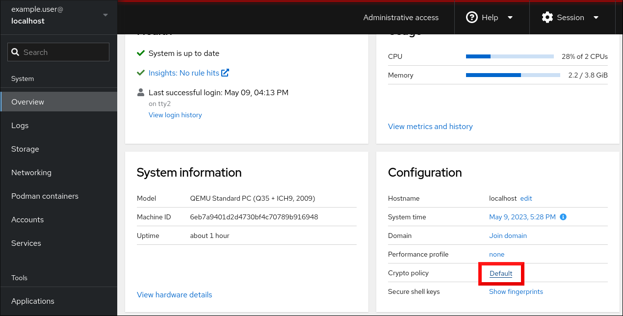
In the Change crypto policy dialog window, click on the policy you want to start using on your system.
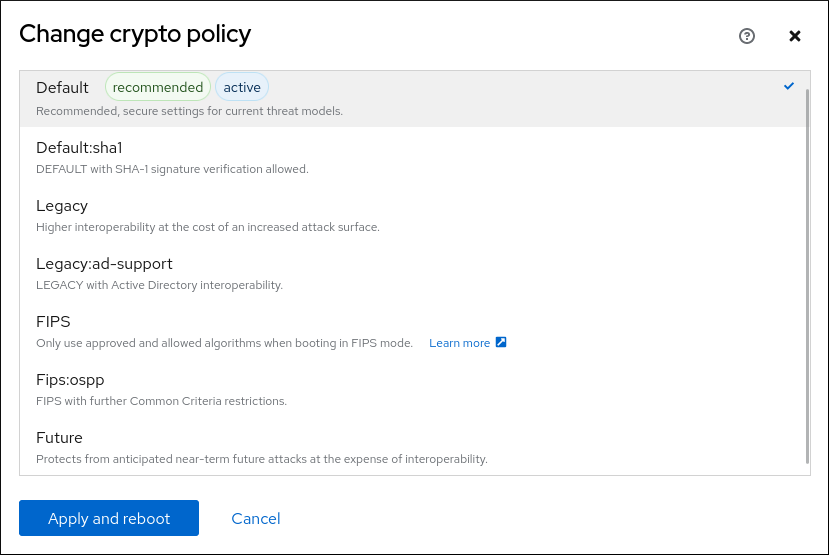
- Click the button.
Verification
After the restart, log back in to web console, and check that the Crypto policy value corresponds to the one you selected.
Alternatively, you can enter the
update-crypto-policies --showcommand to display the current system-wide cryptographic policy in your terminal.
15.5. Excluding an application from following system-wide cryptographic policies
You can customize cryptographic settings used by your application preferably by configuring supported cipher suites and protocols directly in the application.
You can also remove a symlink related to your application from the /etc/crypto-policies/back-ends directory and replace it with your customized cryptographic settings. This configuration prevents the use of system-wide cryptographic policies for applications that use the excluded back end. Furthermore, this modification is not supported by Red Hat.
15.5.1. Examples of opting out of the system-wide cryptographic policies
wget
To customize cryptographic settings used by the wget network downloader, use --secure-protocol and --ciphers options. For example:
$ wget --secure-protocol=TLSv1_1 --ciphers="SECURE128" https://example.com
See the HTTPS (SSL/TLS) Options section of the wget(1) man page for more information.
curl
To specify ciphers used by the curl tool, use the --ciphers option and provide a colon-separated list of ciphers as a value. For example:
$ curl https://example.com --ciphers '@SECLEVEL=0:DES-CBC3-SHA:RSA-DES-CBC3-SHA'
See the curl(1) man page for more information.
Firefox
Even though you cannot opt out of system-wide cryptographic policies in the Firefox web browser, you can further restrict supported ciphers and TLS versions in Firefox’s Configuration Editor. Type about:config in the address bar and change the value of the security.tls.version.min option as required. Setting security.tls.version.min to 1 allows TLS 1.0 as the minimum required, security.tls.version.min 2 enables TLS 1.1, and so on.
OpenSSH
To opt out of the system-wide cryptographic policies for your OpenSSH server, uncomment the line with the CRYPTO_POLICY= variable in the /etc/sysconfig/sshd file. After this change, values that you specify in the Ciphers, MACs, KexAlgoritms, and GSSAPIKexAlgorithms sections in the /etc/ssh/sshd_config file are not overridden.
See the sshd_config(5) man page for more information.
To opt out of system-wide cryptographic policies for your OpenSSH client, perform one of the following tasks:
-
For a given user, override the global
ssh_configwith a user-specific configuration in the~/.ssh/configfile. -
For the entire system, specify the cryptographic policy in a drop-in configuration file located in the
/etc/ssh/ssh_config.d/directory, with a two-digit number prefix smaller than 5, so that it lexicographically precedes the05-redhat.conffile, and with a.confsuffix, for example,04-crypto-policy-override.conf.
See the ssh_config(5) man page for more information.
Libreswan
See the Configuring IPsec connections that opt out of the system-wide crypto policies in the Securing networks document for detailed information.
15.6. Customizing system-wide cryptographic policies with subpolicies
Use this procedure to adjust the set of enabled cryptographic algorithms or protocols.
You can either apply custom subpolicies on top of an existing system-wide cryptographic policy or define such a policy from scratch.
The concept of scoped policies allows enabling different sets of algorithms for different back ends. You can limit each configuration directive to specific protocols, libraries, or services.
Furthermore, directives can use asterisks for specifying multiple values using wildcards.
The /etc/crypto-policies/state/CURRENT.pol file lists all settings in the currently applied system-wide cryptographic policy after wildcard expansion. To make your cryptographic policy more strict, consider using values listed in the /usr/share/crypto-policies/policies/FUTURE.pol file.
You can find example subpolicies in the /usr/share/crypto-policies/policies/modules/ directory. The subpolicy files in this directory contain also descriptions in lines that are commented out.
Customization of system-wide cryptographic policies is available from RHEL 8.2. You can use the concept of scoped policies and the option of using wildcards in RHEL 8.5 and newer.
Procedure
Checkout to the
/etc/crypto-policies/policies/modules/directory:# cd /etc/crypto-policies/policies/modules/Create subpolicies for your adjustments, for example:
# touch MYCRYPTO-1.pmod # touch SCOPES-AND-WILDCARDS.pmodImportantUse upper-case letters in file names of policy modules.
Open the policy modules in a text editor of your choice and insert options that modify the system-wide cryptographic policy, for example:
# vi MYCRYPTO-1.pmodmin_rsa_size = 3072 hash = SHA2-384 SHA2-512 SHA3-384 SHA3-512# vi SCOPES-AND-WILDCARDS.pmod# Disable the AES-128 cipher, all modes cipher = -AES-128-* # Disable CHACHA20-POLY1305 for the TLS protocol (OpenSSL, GnuTLS, NSS, and OpenJDK) cipher@TLS = -CHACHA20-POLY1305 # Allow using the FFDHE-1024 group with the SSH protocol (libssh and OpenSSH) group@SSH = FFDHE-1024+ # Disable all CBC mode ciphers for the SSH protocol (libssh and OpenSSH) cipher@SSH = -*-CBC # Allow the AES-256-CBC cipher in applications using libssh cipher@libssh = AES-256-CBC+- Save the changes in the module files.
Apply your policy adjustments to the
DEFAULTsystem-wide cryptographic policy level:# update-crypto-policies --set DEFAULT:MYCRYPTO-1:SCOPES-AND-WILDCARDSTo make your cryptographic settings effective for already running services and applications, restart the system:
# reboot
Verification
Check that the
/etc/crypto-policies/state/CURRENT.polfile contains your changes, for example:$ cat /etc/crypto-policies/state/CURRENT.pol | grep rsa_size min_rsa_size = 3072
15.7. Disabling SHA-1 by customizing a system-wide cryptographic policy
Because the SHA-1 hash function has an inherently weak design, and advancing cryptanalysis has made it vulnerable to attacks, RHEL 8 does not use SHA-1 by default. Nevertheless, some third-party applications, for example, public signatures, still use SHA-1. To disable the use of SHA-1 in signature algorithms on your system, you can use the NO-SHA1 policy module.
The NO-SHA1 policy module disables the SHA-1 hash function only in signatures and not elsewhere. In particular, the NO-SHA1 module still allows the use of SHA-1 with hash-based message authentication codes (HMAC). This is because HMAC security properties do not rely on the collision resistance of the corresponding hash function, and therefore the recent attacks on SHA-1 have a significantly lower impact on the use of SHA-1 for HMAC.
If your scenario requires disabling a specific key exchange (KEX) algorithm combination, for example, diffie-hellman-group-exchange-sha1, but you still want to use both the relevant KEX and the algorithm in other combinations, see the Red Hat Knowledgebase solution Steps to disable the diffie-hellman-group1-sha1 algorithm in SSH for instructions on opting out of system-wide crypto-policies for SSH and configuring SSH directly.
The module for disabling SHA-1 is available from RHEL 8.3. Customization of system-wide cryptographic policies is available from RHEL 8.2.
Procedure
Apply your policy adjustments to the
DEFAULTsystem-wide cryptographic policy level:# update-crypto-policies --set DEFAULT:NO-SHA1To make your cryptographic settings effective for already running services and applications, restart the system:
# reboot
15.8. Creating and setting a custom system-wide cryptographic policy
For specific scenarios, you can customize the system-wide cryptographic policy by creating and using a complete policy file.
Customization of system-wide cryptographic policies is available from RHEL 8.2.
Procedure
Create a policy file for your customizations:
# cd /etc/crypto-policies/policies/ # touch MYPOLICY.polAlternatively, start by copying one of the four predefined policy levels:
# cp /usr/share/crypto-policies/policies/DEFAULT.pol /etc/crypto-policies/policies/MYPOLICY.polEdit the file with your custom cryptographic policy in a text editor of your choice to fit your requirements, for example:
# vi /etc/crypto-policies/policies/MYPOLICY.polSwitch the system-wide cryptographic policy to your custom level:
# update-crypto-policies --set MYPOLICYTo make your cryptographic settings effective for already running services and applications, restart the system:
# reboot
15.9. Enhancing security with the FUTURE cryptographic policy using the crypto_policies RHEL system role
You can use the crypto_policies RHEL system role to configure the FUTURE policy on your managed nodes. This policy helps to achieve for example:
- Future-proofing against emerging threats: anticipates advancements in computational power.
- Enhanced security: stronger encryption standards require longer key lengths and more secure algorithms.
- Compliance with high-security standards: for example in healthcare, telco, and finance the data sensitivity is high, and availability of strong cryptography is critical.
Typically, FUTURE is suitable for environments handling highly sensitive data, preparing for future regulations, or adopting long-term security strategies.
Legacy systems or software does not have to support the more modern and stricter algorithms and protocols enforced by the FUTURE policy. For example, older systems might not support TLS 1.3 or larger key sizes. This could lead to compatibility problems.
Also, using strong algorithms usually increases the computational workload, which could negatively affect your system performance.
Prerequisites
- You have prepared the control node and the managed nodes
- You are logged in to the control node as a user who can run playbooks on the managed nodes.
-
The account you use to connect to the managed nodes has
sudopermissions on them.
Procedure
Create a playbook file, for example
~/playbook.yml, with the following content:--- - name: Configure cryptographic policies hosts: managed-node-01.example.com tasks: - name: Configure the FUTURE cryptographic security policy on the managed node ansible.builtin.include_role: name: redhat.rhel_system_roles.crypto_policies vars: - crypto_policies_policy: FUTURE - crypto_policies_reboot_ok: trueThe settings specified in the example playbook include the following:
crypto_policies_policy: FUTURE-
Configures the required cryptographic policy (
FUTURE) on the managed node. It can be either the base policy or a base policy with some sub-policies. The specified base policy and sub-policies have to be available on the managed node. The default value isnull. It means that the configuration is not changed and thecrypto_policiesRHEL system role will only collect the Ansible facts. crypto_policies_reboot_ok: true-
Causes the system to reboot after the cryptographic policy change to make sure all of the services and applications will read the new configuration files. The default value is
false.
For details about all variables used in the playbook, see the
/usr/share/ansible/roles/rhel-system-roles.crypto_policies/README.mdfile on the control node.Validate the playbook syntax:
$ ansible-playbook --syntax-check ~/playbook.ymlNote that this command only validates the syntax and does not protect against a wrong but valid configuration.
Run the playbook:
$ ansible-playbook ~/playbook.yml
Because the FIPS:OSPP system-wide subpolicy contains further restrictions for cryptographic algorithms required by the Common Criteria (CC) certification, the system is less interoperable after you set it. For example, you cannot use RSA and DH keys shorter than 3072 bits, additional SSH algorithms, and several TLS groups. Setting FIPS:OSPP also prevents connecting to Red Hat Content Delivery Network (CDN) structure. Furthermore, you cannot integrate Active Directory (AD) into the IdM deployments that use FIPS:OSPP, communication between RHEL hosts using FIPS:OSPP and AD domains might not work, or some AD accounts might not be able to authenticate.
Note that your system is not CC-compliant after you set the FIPS:OSPP cryptographic subpolicy. The only correct way to make your RHEL system compliant with the CC standard is by following the guidance provided in the cc-config package. See the Common Criteria section on the Product compliance Red Hat Customer Portal page for a list of certified RHEL versions, validation reports, and links to CC guides hosted at the National Information Assurance Partnership (NIAP) website.
Verification
On the control node, create another playbook named, for example,
verify_playbook.yml:--- - name: Verification hosts: managed-node-01.example.com tasks: - name: Verify active cryptographic policy ansible.builtin.include_role: name: redhat.rhel_system_roles.crypto_policies - name: Display the currently active cryptographic policy ansible.builtin.debug: var: crypto_policies_activeThe settings specified in the example playbook include the following:
crypto_policies_active-
An exported Ansible fact that contains the currently active policy name in the format as accepted by the
crypto_policies_policyvariable.
Validate the playbook syntax:
$ ansible-playbook --syntax-check ~/verify_playbook.ymlRun the playbook:
$ ansible-playbook ~/verify_playbook.yml TASK [debug] ************************** ok: [host] => { "crypto_policies_active": "FUTURE" }The
crypto_policies_activevariable shows the active policy on the managed node.
Chapter 16. Configuring applications to use cryptographic hardware through PKCS #11
Separating parts of your secret information about dedicated cryptographic devices, such as smart cards and cryptographic tokens for end-user authentication and hardware security modules (HSM) for server applications, provides an additional layer of security. In RHEL, support for cryptographic hardware through the PKCS #11 API is consistent across different applications, and the isolation of secrets on cryptographic hardware is not a complicated task.
16.1. Cryptographic hardware support through PKCS #11
Public-Key Cryptography Standard (PKCS) #11 defines an application programming interface (API) to cryptographic devices that hold cryptographic information and perform cryptographic functions.
PKCS #11 introduces the cryptographic token, an object that presents each hardware or software device to applications in a unified manner. Therefore, applications view devices such as smart cards, which are typically used by persons, and hardware security modules, which are typically used by computers, as PKCS #11 cryptographic tokens.
A PKCS #11 token can store various object types including a certificate; a data object; and a public, private, or secret key. These objects are uniquely identifiable through the PKCS #11 Uniform Resource Identifier (URI) scheme.
A PKCS #11 URI is a standard way to identify a specific object in a PKCS #11 module according to the object attributes. This enables you to configure all libraries and applications with the same configuration string in the form of a URI.
RHEL provides the OpenSC PKCS #11 driver for smart cards by default. However, hardware tokens and HSMs can have their own PKCS #11 modules that do not have their counterpart in the system. You can register such PKCS #11 modules with the p11-kit tool, which acts as a wrapper over the registered smart-card drivers in the system.
To make your own PKCS #11 module work on the system, add a new text file to the /etc/pkcs11/modules/ directory
You can add your own PKCS #11 module into the system by creating a new text file in the /etc/pkcs11/modules/ directory. For example, the OpenSC configuration file in p11-kit looks as follows:
$ cat /usr/share/p11-kit/modules/opensc.module
module: opensc-pkcs11.so16.2. Authenticating by SSH keys stored on a smart card
You can create and store ECDSA and RSA keys on a smart card and authenticate by the smart card on an OpenSSH client. Smart-card authentication replaces the default password authentication.
Prerequisites
-
On the client side, the
openscpackage is installed and thepcscdservice is running.
Procedure
List all keys provided by the OpenSC PKCS #11 module including their PKCS #11 URIs and save the output to the
keys.pubfile:$ ssh-keygen -D pkcs11: > keys.pubTransfer the public key to the remote server. Use the
ssh-copy-idcommand with thekeys.pubfile created in the previous step:$ ssh-copy-id -f -i keys.pub <username@ssh-server-example.com>Connect to <ssh-server-example.com> by using the ECDSA key. You can use just a subset of the URI, which uniquely references your key, for example:
$ ssh -i "pkcs11:id=%01?module-path=/usr/lib64/pkcs11/opensc-pkcs11.so" <ssh-server-example.com> Enter PIN for 'SSH key': [ssh-server-example.com] $Because OpenSSH uses the
p11-kit-proxywrapper and the OpenSC PKCS #11 module is registered to thep11-kittool, you can simplify the previous command:$ ssh -i "pkcs11:id=%01" <ssh-server-example.com> Enter PIN for 'SSH key': [ssh-server-example.com] $If you skip the
id=part of a PKCS #11 URI, OpenSSH loads all keys that are available in the proxy module. This can reduce the amount of typing required:$ ssh -i pkcs11: <ssh-server-example.com> Enter PIN for 'SSH key': [ssh-server-example.com] $Optional: You can use the same URI string in the
~/.ssh/configfile to make the configuration permanent:$ cat ~/.ssh/config IdentityFile "pkcs11:id=%01?module-path=/usr/lib64/pkcs11/opensc-pkcs11.so" $ ssh <ssh-server-example.com> Enter PIN for 'SSH key': [ssh-server-example.com] $The
sshclient utility now automatically uses this URI and the key from the smart card.
16.3. Configuring applications for authentication with certificates on smart cards
Authentication by using smart cards in applications may increase security and simplify automation. You can integrate the Public Key Cryptography Standard (PKCS) #11 URIs into your application by using the following methods:
-
The
Firefoxweb browser automatically loads thep11-kit-proxyPKCS #11 module. This means that every supported smart card in the system is automatically detected. For using TLS client authentication, no additional setup is required and keys and certificates from a smart card are automatically used when a server requests them. -
If your application uses the
GnuTLSorNSSlibrary, it already supports PKCS #11 URIs. Also, applications that rely on theOpenSSLlibrary can access cryptographic hardware modules, including smart cards, through thepkcs11engine provided by theopenssl-pkcs11package. -
Applications that require working with private keys on smart cards and that do not use
NSS,GnuTLS, norOpenSSLcan use thep11-kitAPI directly to work with cryptographic hardware modules, including smart cards, rather than using the PKCS #11 API of specific PKCS #11 modules. With the the
wgetnetwork downloader, you can specify PKCS #11 URIs instead of paths to locally stored private keys and certificates. This might simplify creation of scripts for tasks that require safely stored private keys and certificates. For example:$ wget --private-key 'pkcs11:token=softhsm;id=%01;type=private?pin-value=111111' --certificate 'pkcs11:token=softhsm;id=%01;type=cert' https://example.com/You can also specify PKCS #11 URI when using the
curltool:$ curl --key 'pkcs11:token=softhsm;id=%01;type=private?pin-value=111111' --cert 'pkcs11:token=softhsm;id=%01;type=cert' https://example.com/
16.4. Using HSMs protecting private keys in Apache
The Apache HTTP server can work with private keys stored on hardware security modules (HSMs), which helps to prevent the keys' disclosure and man-in-the-middle attacks. Note that this usually requires high-performance HSMs for busy servers.
For secure communication in the form of the HTTPS protocol, the Apache HTTP server (httpd) uses the OpenSSL library. OpenSSL does not support PKCS #11 natively. To use HSMs, you have to install the openssl-pkcs11 package, which provides access to PKCS #11 modules through the engine interface. You can use a PKCS #11 URI instead of a regular file name to specify a server key and a certificate in the /etc/httpd/conf.d/ssl.conf configuration file, for example:
SSLCertificateFile "pkcs11:id=%01;token=softhsm;type=cert"
SSLCertificateKeyFile "pkcs11:id=%01;token=softhsm;type=private?pin-value=111111"
Install the httpd-manual package to obtain complete documentation for the Apache HTTP Server, including TLS configuration. The directives available in the /etc/httpd/conf.d/ssl.conf configuration file are described in detail in the /usr/share/httpd/manual/mod/mod_ssl.html file.
16.5. Using HSMs protecting private keys in Nginx
The Nginx HTTP server can work with private keys stored on hardware security modules (HSMs), which helps to prevent the keys' disclosure and man-in-the-middle attacks. Note that this usually requires high-performance HSMs for busy servers.
Because Nginx also uses the OpenSSL for cryptographic operations, support for PKCS #11 must go through the openssl-pkcs11 engine. Nginx currently supports only loading private keys from an HSM, and a certificate must be provided separately as a regular file. Modify the ssl_certificate and ssl_certificate_key options in the server section of the /etc/nginx/nginx.conf configuration file:
ssl_certificate /path/to/cert.pem
ssl_certificate_key "engine:pkcs11:pkcs11:token=softhsm;id=%01;type=private?pin-value=111111";
Note that the engine:pkcs11: prefix is needed for the PKCS #11 URI in the Nginx configuration file. This is because the other pkcs11 prefix refers to the engine name.
Chapter 18. Scanning the system for security compliance and vulnerabilities
18.1. Configuration compliance tools in RHEL
You can perform a fully automated compliance audit in Red Hat Enterprise Linux by using the following configuration compliance tools. These tools are based on the Security Content Automation Protocol (SCAP) standard and are designed for automated tailoring of compliance policies.
- SCAP Workbench
-
The
scap-workbenchgraphical utility is designed to perform configuration and vulnerability scans on a single local or remote system. You can also use it to generate security reports based on these scans and evaluations. - OpenSCAP
The
OpenSCAPlibrary, with the accompanyingoscapcommand-line utility, is designed to perform configuration and vulnerability scans on a local system, to validate configuration compliance content, and to generate reports and guides based on these scans and evaluations.ImportantYou can experience memory-consumption problems while using OpenSCAP, which can cause stopping the program prematurely and prevent generating any result files. See the OpenSCAP memory-consumption problems Knowledgebase article for details.
- SCAP Security Guide (SSG)
-
The
scap-security-guidepackage provides collections of security policies for Linux systems. The guidance consists of a catalog of practical hardening advice, linked to government requirements where applicable. The project bridges the gap between generalized policy requirements and specific implementation guidelines. - Script Check Engine (SCE)
-
With SCE, which is an extension to the SCAP protocol, administrators can write their security content by using a scripting language, such as Bash, Python, and Ruby. The SCE extension is provided in the
openscap-engine-scepackage. The SCE itself is not part of the SCAP standard.
To perform automated compliance audits on multiple systems remotely, you can use the OpenSCAP solution for Red Hat Satellite.
18.2. Red Hat Security Advisories OVAL feed
Red Hat Enterprise Linux security auditing capabilities are based on the Security Content Automation Protocol (SCAP) standard. SCAP is a multi-purpose framework of specifications that supports automated configuration, vulnerability and patch checking, technical control compliance activities, and security measurement.
SCAP specifications create an ecosystem where the format of security content is well-known and standardized although the implementation of the scanner or policy editor is not mandated. This enables organizations to build their security policy (SCAP content) once, no matter how many security vendors they employ.
The Open Vulnerability Assessment Language (OVAL) is the essential and oldest component of SCAP. Unlike other tools and custom scripts, OVAL describes a required state of resources in a declarative manner. OVAL code is never executed directly but using an OVAL interpreter tool called scanner. The declarative nature of OVAL ensures that the state of the assessed system is not accidentally modified.
Like all other SCAP components, OVAL is based on XML. The SCAP standard defines several document formats. Each of them includes a different kind of information and serves a different purpose.
Red Hat Product Security helps customers evaluate and manage risk by tracking and investigating all security issues affecting Red Hat customers. It provides timely and concise patches and security advisories on the Red Hat Customer Portal. Red Hat creates and supports OVAL patch definitions, providing machine-readable versions of our security advisories.
Because of differences between platforms, versions, and other factors, Red Hat Product Security qualitative severity ratings of vulnerabilities do not directly align with the Common Vulnerability Scoring System (CVSS) baseline ratings provided by third parties. Therefore, we recommend that you use the RHSA OVAL definitions instead of those provided by third parties.
The RHSA OVAL definitions are available individually and as a complete package, and are updated within an hour of a new security advisory being made available on the Red Hat Customer Portal.
Each OVAL patch definition maps one-to-one to a Red Hat Security Advisory (RHSA). Because an RHSA can contain fixes for multiple vulnerabilities, each vulnerability is listed separately by its Common Vulnerabilities and Exposures (CVE) name and has a link to its entry in our public bug database.
The RHSA OVAL definitions are designed to check for vulnerable versions of RPM packages installed on a system. It is possible to extend these definitions to include further checks, for example, to find out if the packages are being used in a vulnerable configuration. These definitions are designed to cover software and updates shipped by Red Hat. Additional definitions are required to detect the patch status of third-party software.
The Red Hat Insights for Red Hat Enterprise Linux compliance service helps IT security and compliance administrators to assess, monitor, and report on the security policy compliance of Red Hat Enterprise Linux systems. You can also create and manage your SCAP security policies entirely within the compliance service UI.
18.3. Vulnerability scanning
18.3.1. Red Hat Security Advisories OVAL feed
Red Hat Enterprise Linux security auditing capabilities are based on the Security Content Automation Protocol (SCAP) standard. SCAP is a multi-purpose framework of specifications that supports automated configuration, vulnerability and patch checking, technical control compliance activities, and security measurement.
SCAP specifications create an ecosystem where the format of security content is well-known and standardized although the implementation of the scanner or policy editor is not mandated. This enables organizations to build their security policy (SCAP content) once, no matter how many security vendors they employ.
The Open Vulnerability Assessment Language (OVAL) is the essential and oldest component of SCAP. Unlike other tools and custom scripts, OVAL describes a required state of resources in a declarative manner. OVAL code is never executed directly but using an OVAL interpreter tool called scanner. The declarative nature of OVAL ensures that the state of the assessed system is not accidentally modified.
Like all other SCAP components, OVAL is based on XML. The SCAP standard defines several document formats. Each of them includes a different kind of information and serves a different purpose.
Red Hat Product Security helps customers evaluate and manage risk by tracking and investigating all security issues affecting Red Hat customers. It provides timely and concise patches and security advisories on the Red Hat Customer Portal. Red Hat creates and supports OVAL patch definitions, providing machine-readable versions of our security advisories.
Because of differences between platforms, versions, and other factors, Red Hat Product Security qualitative severity ratings of vulnerabilities do not directly align with the Common Vulnerability Scoring System (CVSS) baseline ratings provided by third parties. Therefore, we recommend that you use the RHSA OVAL definitions instead of those provided by third parties.
The RHSA OVAL definitions are available individually and as a complete package, and are updated within an hour of a new security advisory being made available on the Red Hat Customer Portal.
Each OVAL patch definition maps one-to-one to a Red Hat Security Advisory (RHSA). Because an RHSA can contain fixes for multiple vulnerabilities, each vulnerability is listed separately by its Common Vulnerabilities and Exposures (CVE) name and has a link to its entry in our public bug database.
The RHSA OVAL definitions are designed to check for vulnerable versions of RPM packages installed on a system. It is possible to extend these definitions to include further checks, for example, to find out if the packages are being used in a vulnerable configuration. These definitions are designed to cover software and updates shipped by Red Hat. Additional definitions are required to detect the patch status of third-party software.
The Red Hat Insights for Red Hat Enterprise Linux compliance service helps IT security and compliance administrators to assess, monitor, and report on the security policy compliance of Red Hat Enterprise Linux systems. You can also create and manage your SCAP security policies entirely within the compliance service UI.
18.3.2. Scanning the system for vulnerabilities
The oscap command-line utility enables you to scan local systems, validate configuration compliance content, and generate reports and guides based on these scans and evaluations. This utility serves as a front end to the OpenSCAP library and groups its functionalities to modules (sub-commands) based on the type of SCAP content it processes.
Prerequisites
-
The
openscap-scannerandbzip2packages are installed.
Procedure
Download the latest RHSA OVAL definitions for your system:
# wget -O - https://www.redhat.com/security/data/oval/v2/RHEL8/rhel-8.oval.xml.bz2 | bzip2 --decompress > rhel-8.oval.xmlScan the system for vulnerabilities and save results to the vulnerability.html file:
# oscap oval eval --report vulnerability.html rhel-8.oval.xml
Verification
Check the results in a browser of your choice, for example:
$ firefox vulnerability.html &
18.3.3. Scanning remote systems for vulnerabilities
You can check remote systems for vulnerabilities with the OpenSCAP scanner by using the oscap-ssh tool over the SSH protocol.
Prerequisites
-
The
openscap-utilsandbzip2packages are installed on the system you use for scanning. -
The
openscap-scannerpackage is installed on the remote systems. - The SSH server is running on the remote systems.
Procedure
Download the latest RHSA OVAL definitions for your system:
# wget -O - https://www.redhat.com/security/data/oval/v2/RHEL8/rhel-8.oval.xml.bz2 | bzip2 --decompress > rhel-8.oval.xmlScan a remote system for vulnerabilities and save the results to a file:
# oscap-ssh <username>@<hostname> <port> oval eval --report <scan-report.html> rhel-8.oval.xmlReplace:
-
<username>@<hostname>with the user name and host name of the remote system. -
<port>with the port number through which you can access the remote system, for example,22. -
<scan-report.html>with the file name whereoscapsaves the scan results.
-
18.4. Configuration compliance scanning
18.4.1. Configuration compliance in RHEL
You can use configuration compliance scanning to conform to a baseline defined by a specific organization. For example, if you work with the US government, you might have to align your systems with the Operating System Protection Profile (OSPP), and if you are a payment processor, you might have to align your systems with the Payment Card Industry Data Security Standard (PCI-DSS). You can also perform configuration compliance scanning to harden your system security.
Red Hat recommends you follow the Security Content Automation Protocol (SCAP) content provided in the SCAP Security Guide package because it is in line with Red Hat best practices for affected components.
The SCAP Security Guide package provides content which conforms to the SCAP 1.2 and SCAP 1.3 standards. The openscap scanner utility is compatible with both SCAP 1.2 and SCAP 1.3 content provided in the SCAP Security Guide package.
Performing a configuration compliance scanning does not guarantee the system is compliant.
The SCAP Security Guide suite provides profiles for several platforms in a form of data stream documents. A data stream is a file that contains definitions, benchmarks, profiles, and individual rules. Each rule specifies the applicability and requirements for compliance. RHEL provides several profiles for compliance with security policies. In addition to the industry standard, Red Hat data streams also contain information for remediation of failed rules.
Structure of compliance scanning resources
Data stream
├── xccdf
| ├── benchmark
| ├── profile
| | ├──rule reference
| | └──variable
| ├── rule
| ├── human readable data
| ├── oval reference
├── oval ├── ocil reference
├── ocil ├── cpe reference
└── cpe └── remediationA profile is a set of rules based on a security policy, such as OSPP, PCI-DSS, and Health Insurance Portability and Accountability Act (HIPAA). This enables you to audit the system in an automated way for compliance with security standards.
You can modify (tailor) a profile to customize certain rules, for example, password length. For more information about profile tailoring, see Customizing a security profile with SCAP Workbench.
18.4.2. Possible results of an OpenSCAP scan
Depending on the data stream and profile applied to an OpenSCAP scan, as well as various properties of your system, each rule may produce a specific result. These are the possible results with brief explanations of their meanings:
- Pass
- The scan did not find any conflicts with this rule.
- Fail
- The scan found a conflict with this rule.
- Not checked
- OpenSCAP does not perform an automatic evaluation of this rule. Check whether your system conforms to this rule manually.
- Not applicable
- This rule does not apply to the current configuration.
- Not selected
- This rule is not part of the profile. OpenSCAP does not evaluate this rule and does not display these rules in the results.
- Error
-
The scan encountered an error. For additional information, you can enter the
oscapcommand with the--verbose DEVELoption. File a support case on the Red Hat customer portal or open a ticket in the RHEL project in Red Hat Jira. - Unknown
-
The scan encountered an unexpected situation. For additional information, you can enter the
oscapcommand with the`--verbose DEVELoption. File a support case on the Red Hat customer portal or open a ticket in the RHEL project in Red Hat Jira.
18.4.3. Viewing profiles for configuration compliance
Before you decide to use profiles for scanning or remediation, you can list them and check their detailed descriptions using the oscap info subcommand.
Prerequisites
-
The
openscap-scannerandscap-security-guidepackages are installed.
Procedure
List all available files with security compliance profiles provided by the SCAP Security Guide project:
$ ls /usr/share/xml/scap/ssg/content/ ssg-firefox-cpe-dictionary.xml ssg-rhel6-ocil.xml ssg-firefox-cpe-oval.xml ssg-rhel6-oval.xml … ssg-rhel6-ds-1.2.xml ssg-rhel8-oval.xml ssg-rhel8-ds.xml ssg-rhel8-xccdf.xml …Display detailed information about a selected data stream using the
oscap infosubcommand. XML files containing data streams are indicated by the-dsstring in their names. In theProfilessection, you can find a list of available profiles and their IDs:$ oscap info /usr/share/xml/scap/ssg/content/ssg-rhel8-ds.xml Profiles: … Title: Health Insurance Portability and Accountability Act (HIPAA) Id: xccdf_org.ssgproject.content_profile_hipaa Title: PCI-DSS v3.2.1 Control Baseline for Red Hat Enterprise Linux 8 Id: xccdf_org.ssgproject.content_profile_pci-dss Title: OSPP - Protection Profile for General Purpose Operating Systems Id: xccdf_org.ssgproject.content_profile_ospp …Select a profile from the data stream file and display additional details about the selected profile. To do so, use
oscap infowith the--profileoption followed by the last section of the ID displayed in the output of the previous command. For example, the ID of the HIPPA profile isxccdf_org.ssgproject.content_profile_hipaa, and the value for the--profileoption ishipaa:$ oscap info --profile hipaa /usr/share/xml/scap/ssg/content/ssg-rhel8-ds.xml … Profile Title: Health Insurance Portability and Accountability Act (HIPAA) Description: The HIPAA Security Rule establishes U.S. national standards to protect individuals’ electronic personal health information that is created, received, used, or maintained by a covered entity. …
18.4.4. Assessing configuration compliance with a specific baseline
You can determine whether your system or a remote system conforms to a specific baseline, and save the results in a report by using the oscap command-line tool.
Prerequisites
-
The
openscap-scannerandscap-security-guidepackages are installed. - You know the ID of the profile within the baseline with which the system should comply. To find the ID, see the Viewing profiles for configuration compliance section.
Procedure
Scan the local system for compliance with the selected profile and save the scan results to a file:
$ oscap xccdf eval --report <scan-report.html> --profile <profileID> /usr/share/xml/scap/ssg/content/ssg-rhel8-ds.xmlReplace:
-
<scan-report.html>with the file name whereoscapsaves the scan results. -
<profileID>with the profile ID with which the system should comply, for example,hipaa.
-
Optional: Scan a remote system for compliance with the selected profile and save the scan results to a file:
$ oscap-ssh <username>@<hostname> <port> xccdf eval --report <scan-report.html> --profile <profileID> /usr/share/xml/scap/ssg/content/ssg-rhel8-ds.xmlReplace:
-
<username>@<hostname>with the user name and host name of the remote system. -
<port>with the port number through which you can access the remote system. -
<scan-report.html>with the file name whereoscapsaves the scan results. -
<profileID>with the profile ID with which the system should comply, for example,hipaa.
-
18.5. Remediating the system to align with a specific baseline
You can remediate the RHEL system to align with a specific baseline. You can remediate the system to align with any profile provided by the SCAP Security Guide. For the details on listing the available profiles, see the Viewing profiles for configuration compliance section.
If not used carefully, running the system evaluation with the Remediate option enabled might render the system non-functional. Red Hat does not provide any automated method to revert changes made by security-hardening remediations. Remediations are supported on RHEL systems in the default configuration. If your system has been altered after the installation, running remediation might not make it compliant with the required security profile.
Prerequisites
-
The
scap-security-guidepackage is installed.
Procedure
Remediate the system by using the
oscapcommand with the--remediateoption:# oscap xccdf eval --profile <profileID> --remediate /usr/share/xml/scap/ssg/content/ssg-rhel8-ds.xmlReplace
<profileID>with the profile ID with which the system should comply, for example,hipaa.- Restart your system.
Verification
Evaluate compliance of the system with the profile, and save the scan results to a file:
$ oscap xccdf eval --report <scan-report.html> --profile <profileID> /usr/share/xml/scap/ssg/content/ssg-rhel8-ds.xmlReplace:
-
<scan-report.html>with the file name whereoscapsaves the scan results. -
<profileID>with the profile ID with which the system should comply, for example,hipaa.
-
18.6. Remediating the system to align with a specific baseline by using an SSG Ansible Playbook
You can remediate your system to align with a specific baseline by using an Ansible Playbook file from the SCAP Security Guide project. You can remediate to align with any profile provided by the SCAP Security Guide.
If not used carefully, running the system evaluation with the Remediate option enabled might render the system non-functional. Red Hat does not provide any automated method to revert changes made by security-hardening remediations. Remediations are supported on RHEL systems in the default configuration. If your system has been altered after the installation, running remediation might not make it compliant with the required security profile.
Prerequisites
-
The
scap-security-guidepackage is installed. -
The
ansible-corepackage is installed. See the Ansible Installation Guide for more information. -
The
rhc-worker-playbookpackage is installed. - You know the ID of the profile according to which you want to remediate your system. For details, see Viewing profiles for configuration compliance.
RHEL 8.6 or later is installed. For more information about installing RHEL, see Interactively installing RHEL from installation media.
NoteIn RHEL 8.5 and earlier versions, Ansible packages were provided through Ansible Engine instead of Ansible Core, and with a different level of support. Do not use Ansible Engine because the packages might not be compatible with Ansible automation content in RHEL 8.6 and later. For more information, see Scope of support for the Ansible Core package included in the RHEL 9 and RHEL 8.6 and later AppStream repositories.
Procedure
Remediate your system to align with a selected profile by using Ansible:
# ANSIBLE_COLLECTIONS_PATH=/usr/share/rhc-worker-playbook/ansible/collections/ansible_collections/ ansible-playbook -i "localhost," -c local /usr/share/scap-security-guide/ansible/rhel8-playbook-<profileID>.ymlThe
ANSIBLE_COLLECTIONS_PATHenvironment variable is necessary for the command to run the playbook.Replace
<profileID>with the profile ID of the selected profile.- Restart the system.
Verification
Evaluate the compliance of the system with the selected profile, and save the scan results to a file:
# oscap xccdf eval --profile <profileID> --report <scan-report.html> /usr/share/xml/scap/ssg/content/ssg-rhel8-ds.xmlReplace
<scan-report.html>with the file name whereoscapsaves the scan results.
18.7. Creating a remediation Ansible Playbook to align the system with a specific baseline
You can create an Ansible Playbook that contains only the remediations that are required to align your system with a specific baseline. This playbook is smaller because it does not cover already satisfied requirements. Creating the playbook does not modify your system in any way, you only prepare a file for later application.
In RHEL 8.6, Ansible Engine is replaced by the ansible-core package, which contains only built-in modules. Note that many Ansible remediations use modules from the community and Portable Operating System Interface (POSIX) collections, which are not included in the built-in modules. In this case, you can use Bash remediations as a substitute for Ansible remediations. The Red Hat Connector in RHEL 8.6 includes the Ansible modules necessary for the remediation playbooks to function with Ansible Core.
Prerequisites
-
The
scap-security-guidepackage is installed. -
The
ansible-corepackage is installed. See the Ansible Installation Guide for more information. -
The
rhc-worker-playbookpackage is installed. - You know the ID of the profile according to which you want to remediate your system. For details, see Viewing profiles for configuration compliance.
Procedure
Scan the system and save the results:
# oscap xccdf eval --profile <profileID> --results <profile-results.xml> /usr/share/xml/scap/ssg/content/ssg-rhel8-ds.xmlFind the value of the result ID in the file with the results:
# oscap info <profile-results.xml>Generate an Ansible Playbook based on the file generated in step 1:
# oscap xccdf generate fix --fix-type ansible --result-id xccdf_org.open-scap_testresult_xccdf_org.ssgproject.content_profile_<profileID> --output <profile-remediations.yml> <profile-results.xml>-
Review that the generated
<profile-remediations.yml>file contains Ansible remediations for rules that failed in the scan performed in step 1. Remediate your system to align with a selected profile by using Ansible:
# ANSIBLE_COLLECTIONS_PATH=/usr/share/rhc-worker-playbook/ansible/collections/ansible_collections/ ansible-playbook -i "localhost," -c local <profile-remediations.yml>`The
ANSIBLE_COLLECTIONS_PATHenvironment variable is necessary for the command to run the playbook.WarningIf not used carefully, running the system evaluation with the
Remediateoption enabled might render the system non-functional. Red Hat does not provide any automated method to revert changes made by security-hardening remediations. Remediations are supported on RHEL systems in the default configuration. If your system has been altered after the installation, running remediation might not make it compliant with the required security profile.
Verification
Evaluate the compliance of the system with the selected profile, and save the scan results to a file:
# oscap xccdf eval --profile <profileID> --report <scan-report.html> /usr/share/xml/scap/ssg/content/ssg-rhel8-ds.xmlReplace
<scan-report.html>with the file name whereoscapsaves the scan results.
18.8. Creating a remediation Bash script for a later application
Use this procedure to create a Bash script containing remediations that align your system with a security profile such as HIPAA. Using the following steps, you do not do any modifications to your system, you only prepare a file for later application.
Prerequisites
-
The
scap-security-guidepackage is installed on your RHEL system.
Procedure
Use the
oscapcommand to scan the system and to save the results to an XML file. In the following example,oscapevaluates the system against thehipaaprofile:# oscap xccdf eval --profile hipaa --results <hipaa-results.xml> /usr/share/xml/scap/ssg/content/ssg-rhel8-ds.xmlFind the value of the result ID in the file with the results:
# oscap info <hipaa-results.xml>Generate a Bash script based on the results file generated in step 1:
# oscap xccdf generate fix --fix-type bash --result-id <xccdf_org.open-scap_testresult_xccdf_org.ssgproject.content_profile_hipaa> --output <hipaa-remediations.sh> <hipaa-results.xml>-
The
<hipaa-remediations.sh>file contains remediations for rules that failed during the scan performed in step 1. After reviewing this generated file, you can apply it with the./<hipaa-remediations.sh>command when you are in the same directory as this file.
Verification
-
In a text editor of your choice, review that the
<hipaa-remediations.sh>file contains rules that failed in the scan performed in step 1.
18.9. Scanning the system with a customized profile using SCAP Workbench
SCAP Workbench, which is contained in the scap-workbench package, is a graphical utility that enables users to perform configuration and vulnerability scans on a single local or a remote system, perform remediation of the system, and generate reports based on scan evaluations. Note that SCAP Workbench has limited functionality compared with the oscap command-line utility. SCAP Workbench processes security content in the form of data stream files.
18.9.1. Using SCAP Workbench to scan and remediate the system
To evaluate your system against the selected security policy, use the following procedure.
Prerequisites
-
The
scap-workbenchpackage is installed on your system.
Procedure
To run
SCAP Workbenchfrom theGNOME Classicdesktop environment, press the Super key to enter theActivities Overview, typescap-workbench, and then press Enter. Alternatively, use:$ scap-workbench &Select a security policy using either of the following options:
-
Load Contentbutton on the starting window -
Open content from SCAP Security Guide Open Other Contentin theFilemenu, and search the respective XCCDF, SCAP RPM, or data stream file.
-
You can allow automatic correction of the system configuration by selecting the check box. With this option enabled,
SCAP Workbenchattempts to change the system configuration in accordance with the security rules applied by the policy. This process should fix the related checks that fail during the system scan.WarningIf not used carefully, running the system evaluation with the
Remediateoption enabled might render the system non-functional. Red Hat does not provide any automated method to revert changes made by security-hardening remediations. Remediations are supported on RHEL systems in the default configuration. If your system has been altered after the installation, running remediation might not make it compliant with the required security profile.Scan your system with the selected profile by clicking the button.
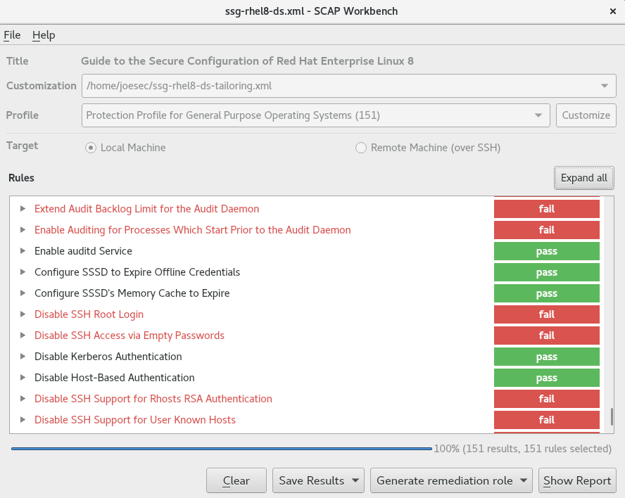
-
To store the scan results in form of an XCCDF, ARF, or HTML file, click the combo box. Choose the
HTML Reportoption to generate the scan report in human-readable format. The XCCDF and ARF (data stream) formats are suitable for further automatic processing. You can repeatedly choose all three options. - To export results-based remediations to a file, use the pop-up menu.
18.9.2. Customizing a security profile with SCAP Workbench
You can customize a security profile by changing parameters in certain rules (for example, minimum password length), removing rules that you cover in a different way, and selecting additional rules, to implement internal policies. You cannot define new rules by customizing a profile.
The following procedure demonstrates the use of SCAP Workbench for customizing (tailoring) a profile. You can also save the tailored profile for use with the oscap command-line utility.
Prerequisites
-
The
scap-workbenchpackage is installed on your system.
Procedure
-
Run
SCAP Workbench, and select the profile to customize by using eitherOpen content from SCAP Security GuideorOpen Other Contentin theFilemenu. To adjust the selected security profile according to your needs, click the button.
This opens the new Customization window that enables you to modify the currently selected profile without changing the original data stream file. Choose a new profile ID.
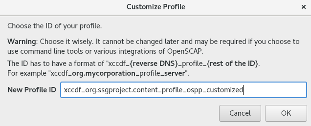
- Find a rule to modify using either the tree structure with rules organized into logical groups or the field.
Include or exclude rules using check boxes in the tree structure, or modify values in rules where applicable.
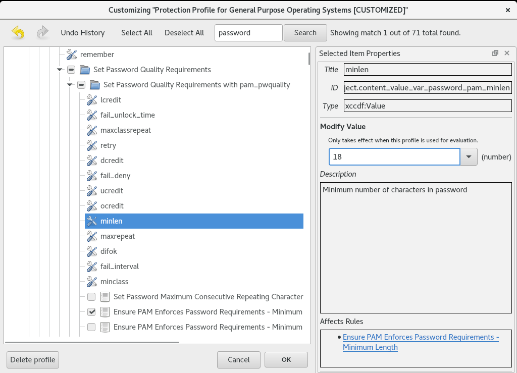
- Confirm the changes by clicking the button.
To store your changes permanently, use one of the following options:
-
Save a customization file separately by using
Save Customization Onlyin theFilemenu. Save all security content at once by
Save Allin theFilemenu.If you select the
Into a directoryoption,SCAP Workbenchsaves both the data stream file and the customization file to the specified location. You can use this as a backup solution.By selecting the
As RPMoption, you can instructSCAP Workbenchto create an RPM package containing the data stream file and the customization file. This is useful for distributing the security content to systems that cannot be scanned remotely, and for delivering the content for further processing.
-
Save a customization file separately by using
Because SCAP Workbench does not support results-based remediations for tailored profiles, use the exported remediations with the oscap command-line utility.
18.10. Scanning container and container images for vulnerabilities
Use this procedure to find security vulnerabilities in a container or a container image.
The oscap-podman command is available from RHEL 8.2. For RHEL 8.1 and 8.0, use the workaround described in the Using OpenSCAP for scanning containers in RHEL 8 Knowledgebase article.
Prerequisites
-
The
openscap-utilsandbzip2packages are installed.
Procedure
Download the latest RHSA OVAL definitions for your system:
# wget -O - https://www.redhat.com/security/data/oval/v2/RHEL8/rhel-8.oval.xml.bz2 | bzip2 --decompress > rhel-8.oval.xmlGet the ID of a container or a container image, for example:
# podman images REPOSITORY TAG IMAGE ID CREATED SIZE registry.access.redhat.com/ubi8/ubi latest 096cae65a207 7 weeks ago 239 MBScan the container or the container image for vulnerabilities and save results to the vulnerability.html file:
# oscap-podman 096cae65a207 oval eval --report vulnerability.html rhel-8.oval.xmlNote that the
oscap-podmancommand requires root privileges, and the ID of a container is the first argument.
Verification
Check the results in a browser of your choice, for example:
$ firefox vulnerability.html &
18.11. Assessing security compliance of a container or a container image with a specific baseline
You can assess the compliance of your container or a container image with a specific security baseline, such as Operating System Protection Profile (OSPP), Payment Card Industry Data Security Standard (PCI-DSS), and Health Insurance Portability and Accountability Act (HIPAA).
The oscap-podman command is available from RHEL 8.2. For RHEL 8.1 and 8.0, use the workaround described in the Using OpenSCAP for scanning containers in RHEL 8 Knowledgebase article.
Prerequisites
-
The
openscap-utilsandscap-security-guidepackages are installed. - You have root access to the system.
Procedure
Find the ID of a container or a container image:
-
To find the ID of a container, enter the
podman ps -acommand. -
To find the ID of a container image, enter the
podman imagescommand.
-
To find the ID of a container, enter the
Evaluate the compliance of the container or container image with a profile and save the scan results into a file:
# oscap-podman <ID> xccdf eval --report <scan-report.html> --profile <profileID> /usr/share/xml/scap/ssg/content/ssg-rhel8-ds.xmlReplace:
-
<ID>with the ID of your container or container image -
<scan-report.html>with the file name whereoscapsaves the scan results -
<profileID>with the profile ID with which the system should comply, for example,hipaa,ospp, orpci-dss
-
Verification
Check the results in a browser of your choice, for example:
$ firefox <scan-report.html> &
The rules marked as notapplicable apply only to bare-metal and virtualized systems and not to containers or container images.
18.12. Checking integrity with AIDE
Advanced Intrusion Detection Environment (AIDE) is a utility that creates a database of files on the system, and then uses that database to ensure file integrity and detect system intrusions.
18.12.1. Installing AIDE
To start file-integrity checking with AIDE, you must install the corresponding package and initiate the AIDE database.
Prerequisites
-
The
AppStreamrepository is enabled.
Procedure
Install the
aidepackage:# yum install aideGenerate an initial database:
# aide --init Start timestamp: 2024-07-08 10:39:23 -0400 (AIDE 0.16) AIDE initialized database at /var/lib/aide/aide.db.new.gz Number of entries: 55856 --------------------------------------------------- The attributes of the (uncompressed) database(s): --------------------------------------------------- /var/lib/aide/aide.db.new.gz … SHA512 : mZaWoGzL2m6ZcyyZ/AXTIowliEXWSZqx IFYImY4f7id4u+Bq8WeuSE2jasZur/A4 FPBFaBkoCFHdoE/FW/V94Q==-
Optional: In the default configuration, the
aide --initcommand checks just a set of directories and files defined in the/etc/aide.conffile. To include additional directories or files in the AIDE database, and to change their watched parameters, edit/etc/aide.confaccordingly. To start using the database, remove the
.newsubstring from the initial database file name:# mv /var/lib/aide/aide.db.new.gz /var/lib/aide/aide.db.gz-
Optional: To change the location of the AIDE database, edit the
/etc/aide.conffile and modify theDBDIRvalue. For additional security, store the database, configuration, and the/usr/sbin/aidebinary file in a secure location such as a read-only media.
18.12.2. Performing integrity checks with AIDE
You can use the crond service to schedule regular file-integrity checks with AIDE.
Prerequisites
- AIDE is properly installed and its database is initialized. See Installing AIDE
Procedure
To initiate a manual check:
# aide --check Start timestamp: 2024-07-08 10:43:46 -0400 (AIDE 0.16) AIDE found differences between database and filesystem!! Summary: Total number of entries: 55856 Added entries: 0 Removed entries: 0 Changed entries: 1 --------------------------------------------------- Changed entries: --------------------------------------------------- f ... ..S : /root/.viminfo --------------------------------------------------- Detailed information about changes: --------------------------------------------------- File: /root/.viminfo SELinux : system_u:object_r:admin_home_t:s | unconfined_u:object_r:admin_home 0 | _t:s0 …At a minimum, configure the system to run AIDE weekly. Optimally, run AIDE daily. For example, to schedule a daily execution of AIDE at 04:05 a.m. by using the
croncommand, add the following line to the/etc/crontabfile:05 4 * * * root /usr/sbin/aide --check
18.12.3. Updating an AIDE database
After verifying the changes of your system, such as package updates or configuration files adjustments, update also your baseline AIDE database.
Prerequisites
- AIDE is properly installed and its database is initialized. See Installing AIDE
Procedure
Update your baseline AIDE database:
# aide --updateThe
aide --updatecommand creates the/var/lib/aide/aide.db.new.gzdatabase file.-
To start using the updated database for integrity checks, remove the
.newsubstring from the file name.
18.12.4. File-integrity tools: AIDE and IMA
Red Hat Enterprise Linux provides several tools for checking and preserving the integrity of files and directories on your system. The following table helps you decide which tool better fits your scenario.
| Question | Advanced Intrusion Detection Environment (AIDE) | Integrity Measurement Architecture (IMA) |
|---|---|---|
| What | AIDE is a utility that creates a database of files and directories on the system. This database serves for checking file integrity and detect intrusion detection. | IMA detects if a file is altered by checking file measurement (hash values) compared to previously stored extended attributes. |
| How | AIDE uses rules to compare the integrity state of the files and directories. | IMA uses file hash values to detect the intrusion. |
| Why | Detection - AIDE detects if a file is modified by verifying the rules. | Detection and Prevention - IMA detects and prevents an attack by replacing the extended attribute of a file. |
| Usage | AIDE detects a threat when the file or directory is modified. | IMA detects a threat when someone tries to alter the entire file. |
| Extension | AIDE checks the integrity of files and directories on the local system. | IMA ensures security on the local and remote systems. |
18.13. Encrypting block devices using LUKS
By using the disk encryption, you can protect the data on a block device by encrypting it. To access the device’s decrypted contents, enter a passphrase or key as authentication. This is important for mobile computers and removable media because it helps to protect the device’s contents even if it has been physically removed from the system. The LUKS format is a default implementation of block device encryption in Red Hat Enterprise Linux.
18.13.1. LUKS disk encryption
Linux Unified Key Setup-on-disk-format (LUKS) provides a set of tools that simplifies managing the encrypted devices. With LUKS, you can encrypt block devices and enable multiple user keys to decrypt a master key. For bulk encryption of the partition, use this master key.
Red Hat Enterprise Linux uses LUKS to perform block device encryption. By default, the option to encrypt the block device is unchecked during the installation. If you select the option to encrypt your disk, the system prompts you for a passphrase every time you boot the computer. This passphrase unlocks the bulk encryption key that decrypts your partition. If you want to modify the default partition table, you can select the partitions that you want to encrypt. This is set in the partition table settings.
Ciphers
The default cipher used for LUKS is aes-xts-plain64. The default key size for LUKS is 512 bits. The default key size for LUKS with Anaconda XTS mode is 512 bits. The following are the available ciphers:
- Advanced Encryption Standard (AES)
- Twofish
- Serpent
Operations performed by LUKS
- LUKS encrypts entire block devices and is therefore well-suited for protecting contents of mobile devices such as removable storage media or laptop disk drives.
- The underlying contents of the encrypted block device are arbitrary, which makes it useful for encrypting swap devices. This can also be useful with certain databases that use specially formatted block devices for data storage.
- LUKS uses the existing device mapper kernel subsystem.
- LUKS provides passphrase strengthening, which protects against dictionary attacks.
- LUKS devices contain multiple key slots, which means you can add backup keys or passphrases.
LUKS is not recommended for the following scenarios:
- Disk-encryption solutions such as LUKS protect the data only when your system is off. After the system is on and LUKS has decrypted the disk, the files on that disk are available to anyone who have access to them.
- Scenarios that require multiple users to have distinct access keys to the same device. The LUKS1 format provides eight key slots and LUKS2 provides up to 32 key slots.
- Applications that require file-level encryption.
18.13.2. LUKS versions in RHEL
In Red Hat Enterprise Linux, the default format for LUKS encryption is LUKS2. The old LUKS1 format remains fully supported and it is provided as a format compatible with earlier Red Hat Enterprise Linux releases. LUKS2 re-encryption is considered more robust and safe to use as compared to LUKS1 re-encryption.
The LUKS2 format enables future updates of various parts without a need to modify binary structures. Internally it uses JSON text format for metadata, provides redundancy of metadata, detects metadata corruption, and automatically repairs from a metadata copy.
Do not use LUKS2 in systems that support only LUKS1 because LUKS2 and LUKS1 use different commands to encrypt the disk. Using the wrong command for a LUKS version might cause data loss.
| LUKS version | Encryption command |
|---|---|
| LUKS2 |
|
| LUKS1 |
|
Online re-encryption
The LUKS2 format supports re-encrypting encrypted devices while the devices are in use. For example, you do not have to unmount the file system on the device to perform the following tasks:
- Changing the volume key
Changing the encryption algorithm
When encrypting a non-encrypted device, you must still unmount the file system. You can remount the file system after a short initialization of the encryption.
The LUKS1 format does not support online re-encryption.
Conversion
In certain situations, you can convert LUKS1 to LUKS2. The conversion is not possible specifically in the following scenarios:
-
A LUKS1 device is marked as being used by a Policy-Based Decryption (PBD) Clevis solution. The
cryptsetuptool does not convert the device when someluksmetametadata are detected. - A device is active. The device must be in an inactive state before any conversion is possible.
18.13.3. Options for data protection during LUKS2 re-encryption
LUKS2 provides several options that prioritize performance or data protection during the re-encryption process. It provides the following modes for the resilience option, and you can select any of these modes by using the cryptsetup reencrypt --resilience resilience-mode /dev/<device_ID> command, where you can replace <device_ID> with the ID of your device.
checksumThe default mode. It balances data protection and performance.
This mode stores individual checksums of the sectors in the re-encryption area, which the recovery process can detect for the sectors that were re-encrypted by LUKS2. The mode requires that the block device sector write is atomic.
journal- The safest mode but also the slowest. Since this mode journals the re-encryption area in the binary area, the LUKS2 writes the data twice.
none-
The
nonemode prioritizes performance and provides no data protection. It protects the data only against safe process termination, such as theSIGTERMsignal or the user pressing Ctrl+C key. Any unexpected system failure or application failure might result in data corruption.
If a LUKS2 re-encryption process terminates unexpectedly by force, LUKS2 can perform the recovery in one of the following ways:
- Automatically
By performing any one of the following actions triggers the automatic recovery action during the next LUKS2 device open action:
-
Executing the
cryptsetup opencommand. -
Attaching the device with the
systemd-cryptsetupcommand.
-
Executing the
- Manually
-
By using the
cryptsetup repair /dev/<device_ID>command on the LUKS2 device.
18.13.4. Encrypting existing data on a block device using LUKS2
You can encrypt the existing data on a not yet encrypted device by using the LUKS2 format. A new LUKS header is stored in the head of the device.
Prerequisites
- The block device has a file system.
You have backed up your data.
WarningYou might lose your data during the encryption process due to a hardware, kernel, or human failure. Ensure that you have a reliable backup before you start encrypting the data.
Procedure
Unmount all file systems on the device that you plan to encrypt, for example:
# umount /dev/mapper/vg00-lv00Make free space for storing a LUKS header. Use one of the following options that suits your scenario:
In the case of encrypting a logical volume, you can extend the logical volume without resizing the file system. For example:
# lvextend -L+32M /dev/mapper/vg00-lv00-
Extend the partition by using partition management tools, such as
parted. -
Shrink the file system on the device. You can use the
resize2fsutility for the ext2, ext3, or ext4 file systems. Note that you cannot shrink the XFS file system.
Initialize the encryption:
# cryptsetup reencrypt --encrypt --init-only --reduce-device-size 32M /dev/mapper/vg00-lv00 lv00_encrypted /dev/mapper/lv00_encrypted is now active and ready for online encryption.Mount the device:
# mount /dev/mapper/lv00_encrypted /mnt/lv00_encryptedAdd an entry for a persistent mapping to the
/etc/crypttabfile:Find the
luksUUID:# cryptsetup luksUUID /dev/mapper/vg00-lv00 a52e2cc9-a5be-47b8-a95d-6bdf4f2d9325Open
/etc/crypttabin a text editor of your choice and add a device in this file:$ vi /etc/crypttab lv00_encrypted UUID=a52e2cc9-a5be-47b8-a95d-6bdf4f2d9325 noneReplace a52e2cc9-a5be-47b8-a95d-6bdf4f2d9325 with your device’s
luksUUID.Refresh initramfs with
dracut:$ dracut -f --regenerate-all
Add an entry for a persistent mounting to the
/etc/fstabfile:Find the file system’s UUID of the active LUKS block device:
$ blkid -p /dev/mapper/lv00_encrypted /dev/mapper/lv00-encrypted: UUID="37bc2492-d8fa-4969-9d9b-bb64d3685aa9" BLOCK_SIZE="4096" TYPE="xfs" USAGE="filesystem"Open
/etc/fstabin a text editor of your choice and add a device in this file, for example:$ vi /etc/fstab UUID=37bc2492-d8fa-4969-9d9b-bb64d3685aa9 /home auto rw,user,auto 0Replace 37bc2492-d8fa-4969-9d9b-bb64d3685aa9 with your file system’s UUID.
Resume the online encryption:
# cryptsetup reencrypt --resume-only /dev/mapper/vg00-lv00 Enter passphrase for /dev/mapper/vg00-lv00: Auto-detected active dm device 'lv00_encrypted' for data device /dev/mapper/vg00-lv00. Finished, time 00:31.130, 10272 MiB written, speed 330.0 MiB/s
Verification
Verify if the existing data was encrypted:
# cryptsetup luksDump /dev/mapper/vg00-lv00 LUKS header information Version: 2 Epoch: 4 Metadata area: 16384 [bytes] Keyslots area: 16744448 [bytes] UUID: a52e2cc9-a5be-47b8-a95d-6bdf4f2d9325 Label: (no label) Subsystem: (no subsystem) Flags: (no flags) Data segments: 0: crypt offset: 33554432 [bytes] length: (whole device) cipher: aes-xts-plain64 [...]View the status of the encrypted blank block device:
# cryptsetup status lv00_encrypted /dev/mapper/lv00_encrypted is active and is in use. type: LUKS2 cipher: aes-xts-plain64 keysize: 512 bits key location: keyring device: /dev/mapper/vg00-lv00
18.13.5. Encrypting existing data on a block device using LUKS2 with a detached header
You can encrypt existing data on a block device without creating free space for storing a LUKS header. The header is stored in a detached location, which also serves as an additional layer of security. The procedure uses the LUKS2 encryption format.
Prerequisites
- The block device has a file system.
Your data is backed up.
WarningYou might lose your data during the encryption process due to a hardware, kernel, or human failure. Ensure that you have a reliable backup before you start encrypting the data.
Procedure
Unmount all file systems on the device, for example:
# umount /dev/<nvme0n1p1>Replace
<nvme0n1p1>with the device identifier corresponding to the partition you want to unmount.Initialize the encryption:
# cryptsetup reencrypt --encrypt --init-only --header </home/header> /dev/<nvme0n1p1> <nvme_encrypted> WARNING! ======== Header file does not exist, do you want to create it? Are you sure? (Type 'yes' in capital letters): YES Enter passphrase for </home/header>: Verify passphrase: /dev/mapper/<nvme_encrypted> is now active and ready for online encryption.Replace:
-
</home/header>with a path to the file with a detached LUKS header. The detached LUKS header has to be accessible to unlock the encrypted device later. -
<nvme_encrypted>with the name of the device mapper that is created after encryption.
-
Mount the device:
# mount /dev/mapper/<nvme_encrypted> /mnt/<nvme_encrypted>Add an entry for a persistent mapping to the
/etc/crypttabfile:# <nvme_encrypted> /dev/disk/by-id/<nvme-partition-id> none header=</home/header>Replace
<nvme-partition-id>with the identifier of the NVMe partition.Regenerate initramfs with
dracut:# dracut -f --regenerate-all -vAdd an entry for a persistent mounting to the
/etc/fstabfile:Find the file system’s UUID of the active LUKS block device:
$ blkid -p /dev/mapper/<nvme_encrypted> /dev/mapper/<nvme_encrypted>: UUID="37bc2492-d8fa-4969-9d9b-bb64d3685aa9" BLOCK_SIZE="4096" TYPE="xfs" USAGE="filesystem"Open
/etc/fstabin a text editor and add a device in this file, for example:UUID=<file_system_UUID> /home auto rw,user,auto 0Replace
<file_system_UUID>with the file system’s UUID found in the previous step.
Resume the online encryption:
# cryptsetup reencrypt --resume-only --header </home/header> /dev/<nvme0n1p1> Enter passphrase for /dev/<nvme0n1p1>: Auto-detected active dm device '<nvme_encrypted>' for data device /dev/<nvme0n1p1>. Finished, time 00m51s, 10 GiB written, speed 198.2 MiB/s
Verification
Verify if the existing data on a block device using LUKS2 with a detached header is encrypted:
# cryptsetup luksDump </home/header> LUKS header information Version: 2 Epoch: 88 Metadata area: 16384 [bytes] Keyslots area: 16744448 [bytes] UUID: c4f5d274-f4c0-41e3-ac36-22a917ab0386 Label: (no label) Subsystem: (no subsystem) Flags: (no flags) Data segments: 0: crypt offset: 0 [bytes] length: (whole device) cipher: aes-xts-plain64 sector: 512 [bytes] [...]View the status of the encrypted blank block device:
# cryptsetup status <nvme_encrypted> /dev/mapper/<nvme_encrypted> is active and is in use. type: LUKS2 cipher: aes-xts-plain64 keysize: 512 bits key location: keyring device: /dev/<nvme0n1p1>
18.13.6. Encrypting a blank block device using LUKS2
You can encrypt a blank block device, which you can use for an encrypted storage by using the LUKS2 format.
Prerequisites
-
A blank block device. You can use commands such as
lsblkto find if there is no real data on that device, for example, a file system.
Procedure
Setup a partition as an encrypted LUKS partition:
# cryptsetup luksFormat /dev/nvme0n1p1 WARNING! ======== This will overwrite data on /dev/nvme0n1p1 irrevocably. Are you sure? (Type 'yes' in capital letters): YES Enter passphrase for /dev/nvme0n1p1: Verify passphrase:Open an encrypted LUKS partition:
# cryptsetup open /dev/nvme0n1p1 nvme0n1p1_encrypted Enter passphrase for /dev/nvme0n1p1:This unlocks the partition and maps it to a new device by using the device mapper. To not overwrite the encrypted data, this command alerts the kernel that the device is an encrypted device and addressed through LUKS by using the
/dev/mapper/device_mapped_namepath.Create a file system to write encrypted data to the partition, which must be accessed through the device mapped name:
# mkfs -t ext4 /dev/mapper/nvme0n1p1_encryptedMount the device:
# mount /dev/mapper/nvme0n1p1_encrypted mount-point
Verification
Verify if the blank block device is encrypted:
# cryptsetup luksDump /dev/nvme0n1p1 LUKS header information Version: 2 Epoch: 3 Metadata area: 16384 [bytes] Keyslots area: 16744448 [bytes] UUID: 34ce4870-ffdf-467c-9a9e-345a53ed8a25 Label: (no label) Subsystem: (no subsystem) Flags: (no flags) Data segments: 0: crypt offset: 16777216 [bytes] length: (whole device) cipher: aes-xts-plain64 sector: 512 [bytes] [...]View the status of the encrypted blank block device:
# cryptsetup status nvme0n1p1_encrypted /dev/mapper/nvme0n1p1_encrypted is active and is in use. type: LUKS2 cipher: aes-xts-plain64 keysize: 512 bits key location: keyring device: /dev/nvme0n1p1 sector size: 512 offset: 32768 sectors size: 20938752 sectors mode: read/write
18.13.7. Configuring the LUKS passphrase in the web console
If you want to add encryption to an existing logical volume on your system, you can only do so through formatting the volume.
Prerequisites
- You have installed the RHEL 8 web console.
- You have enabled the cockpit service.
Your user account is allowed to log in to the web console.
For instructions, see Installing and enabling the web console.
-
The
cockpit-storagedpackage is installed on your system. - Available existing logical volume without encryption.
Procedure
Log in to the RHEL 8 web console.
For details, see Logging in to the web console.
- In the panel, click Storage.
- In the Storage table, click the menu button for the storage device you want to encrypt and click .
- In the Encryption field, select the encryption specification, LUKS1 or LUKS2.
- Set and confirm your new passphrase.
- Optional: Modify further encryption options.
- Finalize formatting settings.
- Click Format.
18.13.8. Changing the LUKS passphrase in the web console
Change a LUKS passphrase on an encrypted disk or partition in the web console.
Prerequisites
- You have installed the RHEL 8 web console.
- You have enabled the cockpit service.
Your user account is allowed to log in to the web console.
For instructions, see Installing and enabling the web console.
-
The
cockpit-storagedpackage is installed on your system.
Procedure
Log in to the RHEL 8 web console.
For details, see Logging in to the web console.
- In the panel, click Storage.
- In the Storage table, select the disk with encrypted data.
- On the disk page, scroll to the Keys section and click the edit button.
In the Change passphrase dialog window:
- Enter your current passphrase.
- Enter your new passphrase.
- Confirm your new passphrase.
- Click Save.
18.13.9. Changing the LUKS passphrase by using the command line
Change a LUKS passphrase on an encrypted disk or partition by using the command line. With the cryptsetup utility, you can control the encryption process with a variety of configuration options and functions, and integrate it in existing automation workflows.
Prerequisites
-
You have
rootprivileges or permissions to enter administrative commands withsudo.
Procedure
Change the existing passphrase on the LUKS encrypted device:
# cryptsetup luksChangeKey /dev/<device_ID>Replace
<device_ID>with the device designator, for example,sda.If you have multiple key slots configured, you can specify the slot to work with:
# cryptsetup luksChangeKey /dev/<device_ID> --key-slot <slot_number>Replace
<slot_number>with the number of the key slot you want to modify.Insert the current passphrase and the new passphrase:
Enter passphrase to be changed: Enter new passphrase: Verify passphrase:Validate the new passphrase:
# cryptsetup --verbose open --test-passphrase /dev/<device_ID>
Verification
Verify that the new passphrase can unlock the device:
Enter passphrase for /dev/<device_ID>: Key slot <slot_number> unlocked. Command successful.
18.13.10. Creating a LUKS2 encrypted volume by using the storage RHEL system role
You can use the storage role to create and configure a volume encrypted with LUKS by running an Ansible playbook.
Prerequisites
- You have prepared the control node and the managed nodes
- You are logged in to the control node as a user who can run playbooks on the managed nodes.
-
The account you use to connect to the managed nodes has
sudopermissions on them.
Procedure
Store your sensitive variables in an encrypted file:
Create the vault:
$ ansible-vault create ~/vault.yml New Vault password: <vault_password> Confirm New Vault password: <vault_password>After the
ansible-vault createcommand opens an editor, enter the sensitive data in the<key>: <value>format:luks_password: <password>- Save the changes, and close the editor. Ansible encrypts the data in the vault.
Create a playbook file, for example
~/playbook.yml, with the following content:--- - name: Manage local storage hosts: managed-node-01.example.com vars_files: - ~/vault.yml tasks: - name: Create and configure a volume encrypted with LUKS ansible.builtin.include_role: name: redhat.rhel_system_roles.storage vars: storage_volumes: - name: barefs type: disk disks: - sdb fs_type: xfs fs_label: <label> mount_point: /mnt/data encryption: true encryption_password: "{{ luks_password }}"For details about all variables used in the playbook, see the
/usr/share/ansible/roles/rhel-system-roles.storage/README.mdfile on the control node.Validate the playbook syntax:
$ ansible-playbook --ask-vault-pass --syntax-check ~/playbook.ymlNote that this command only validates the syntax and does not protect against a wrong but valid configuration.
Run the playbook:
$ ansible-playbook --ask-vault-pass ~/playbook.yml
Verification
Find the
luksUUIDvalue of the LUKS encrypted volume:# ansible managed-node-01.example.com -m command -a 'cryptsetup luksUUID /dev/sdb' 4e4e7970-1822-470e-b55a-e91efe5d0f5cView the encryption status of the volume:
# ansible managed-node-01.example.com -m command -a 'cryptsetup status luks-4e4e7970-1822-470e-b55a-e91efe5d0f5c' /dev/mapper/luks-4e4e7970-1822-470e-b55a-e91efe5d0f5c is active and is in use. type: LUKS2 cipher: aes-xts-plain64 keysize: 512 bits key location: keyring device: /dev/sdb ...Verify the created LUKS encrypted volume:
# ansible managed-node-01.example.com -m command -a 'cryptsetup luksDump /dev/sdb' LUKS header information Version: 2 Epoch: 3 Metadata area: 16384 [bytes] Keyslots area: 16744448 [bytes] UUID: 4e4e7970-1822-470e-b55a-e91efe5d0f5c Label: (no label) Subsystem: (no subsystem) Flags: (no flags) Data segments: 0: crypt offset: 16777216 [bytes] length: (whole device) cipher: aes-xts-plain64 sector: 512 [bytes] ...
18.14. Configuring automated unlocking of encrypted volumes by using policy-based decryption
Policy-Based Decryption (PBD) is a collection of technologies that enable unlocking encrypted root and secondary volumes of hard drives on physical and virtual machines. PBD uses a variety of unlocking methods, such as user passwords, a Trusted Platform Module (TPM) device, a PKCS #11 device connected to a system, for example, a smart card, or a special network server.
PBD allows combining different unlocking methods into a policy, which makes it possible to unlock the same volume in different ways. The current implementation of the PBD in RHEL consists of the Clevis framework and plug-ins called pins. Each pin provides a separate unlocking capability. Currently, the following pins are available:
tang- Allows unlocking volumes by using a network server.
tpm2- Allows unlocking volumes by using a TPM2 policy.
sss- Allows deploying high-availability systems by using the Shamir’s Secret Sharing (SSS) cryptographic scheme.
18.14.1. Network-bound disk encryption
The Network Bound Disc Encryption (NBDE) is a subcategory of Policy-Based Decryption (PBD) that allows binding encrypted volumes to a special network server. The current implementation of the NBDE includes a Clevis pin for the Tang server and the Tang server itself.
In RHEL, NBDE is implemented through the following components and technologies:
Figure 18.1. NBDE scheme when using a LUKS1-encrypted volume. The luksmeta package is not used for LUKS2 volumes.
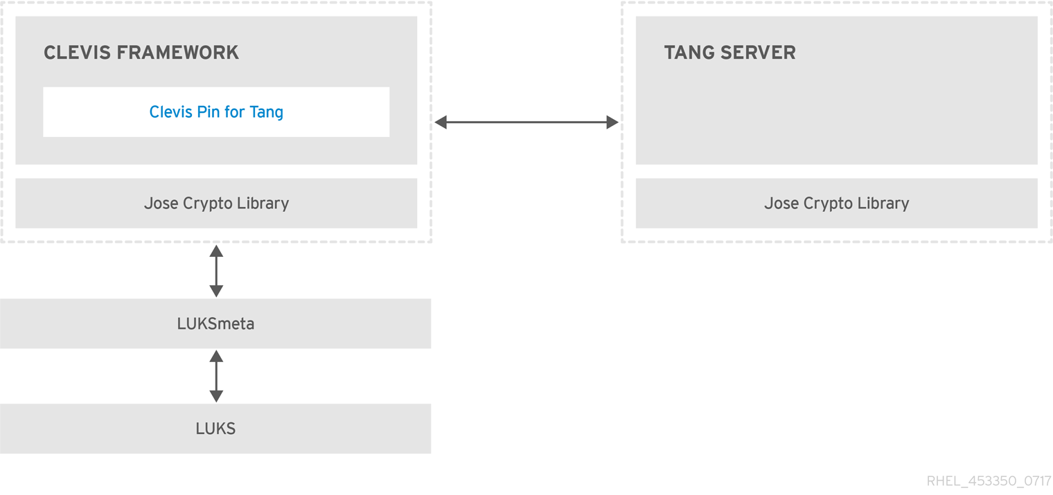
Tang is a server for binding data to network presence. It makes a system containing your data available when the system is bound to a certain secure network. Tang is stateless and does not require TLS or authentication. Unlike escrow-based solutions, where the server stores all encryption keys and has knowledge of every key ever used, Tang never interacts with any client keys, so it never gains any identifying information from the client.
Clevis is a pluggable framework for automated decryption. In NBDE, Clevis provides automated unlocking of LUKS volumes. The clevis package provides the client side of the feature.
A Clevis pin is a plug-in into the Clevis framework. One of such pins is a plug-in that implements interactions with the NBDE server - Tang.
Clevis and Tang are generic client and server components that provide network-bound encryption. In RHEL, they are used in conjunction with LUKS to encrypt and decrypt root and non-root storage volumes to accomplish Network-Bound Disk Encryption.
Both client- and server-side components use the José library to perform encryption and decryption operations.
When you begin provisioning NBDE, the Clevis pin for Tang server gets a list of the Tang server’s advertised asymmetric keys. Alternatively, since the keys are asymmetric, a list of Tang’s public keys can be distributed out of band so that clients can operate without access to the Tang server. This mode is called offline provisioning.
The Clevis pin for Tang uses one of the public keys to generate a unique, cryptographically-strong encryption key. Once the data is encrypted using this key, the key is discarded. The Clevis client should store the state produced by this provisioning operation in a convenient location. This process of encrypting data is the provisioning step.
The LUKS version 2 (LUKS2) is the default disk-encryption format in RHEL, hence, the provisioning state for NBDE is stored as a token in a LUKS2 header. The leveraging of provisioning state for NBDE by the luksmeta package is used only for volumes encrypted with LUKS1.
The Clevis pin for Tang supports both LUKS1 and LUKS2 without specification need. Clevis can encrypt plain-text files but you have to use the cryptsetup tool for encrypting block devices. See the Encrypting block devices using LUKS for more information.
When the client is ready to access its data, it loads the metadata produced in the provisioning step and it responds to recover the encryption key. This process is the recovery step.
In NBDE, Clevis binds a LUKS volume using a pin so that it can be automatically unlocked. After successful completion of the binding process, the disk can be unlocked using the provided Dracut unlocker.
If the kdump kernel crash dumping mechanism is set to save the content of the system memory to a LUKS-encrypted device, you are prompted for entering a password during the second kernel boot.
18.14.2. Deploying a Tang server with SELinux in enforcing mode
You can use a Tang server to automatically unlock LUKS-encrypted volumes on Clevis-enabled clients. In the minimalistic scenario, you deploy a Tang server on port 80 by installing the tang package and entering the systemctl enable tangd.socket --now command. The following example procedure demonstrates the deployment of a Tang server running on a custom port as a confined service in SELinux enforcing mode.
Prerequisites
-
The
policycoreutils-python-utilspackage and its dependencies are installed. -
The
firewalldservice is running.
Procedure
To install the
tangpackage and its dependencies, enter the following command asroot:# yum install tangPick an unoccupied port, for example, 7500/tcp, and allow the
tangdservice to bind to that port:# semanage port -a -t tangd_port_t -p tcp 7500Note that a port can be used only by one service at a time, and thus an attempt to use an already occupied port implies the
ValueError: Port already definederror message.Open the port in the firewall:
# firewall-cmd --add-port=7500/tcp # firewall-cmd --runtime-to-permanentEnable the
tangdservice:# systemctl enable tangd.socketCreate an override file:
# systemctl edit tangd.socketIn the following editor screen, which opens an empty
override.conffile located in the/etc/systemd/system/tangd.socket.d/directory, change the default port for the Tang server from 80 to the previously picked number by adding the following lines:[Socket] ListenStream= ListenStream=7500ImportantInsert the previous code snippet between the lines starting with
# Anything between hereand# Lines below this, otherwise the system discards your changes.-
Save the changes and exit the editor. In the default
vieditor, you can do that by pressing Esc to switch into command mode, entering:wq, and pressing Enter. Reload the changed configuration:
# systemctl daemon-reloadCheck that your configuration is working:
# systemctl show tangd.socket -p Listen Listen=[::]:7500 (Stream)Start the
tangdservice:# systemctl restart tangd.socketBecause
tangduses thesystemdsocket activation mechanism, the server starts as soon as the first connection comes in. A new set of cryptographic keys is automatically generated at the first start. To perform cryptographic operations such as manual key generation, use thejoseutility.
Verification
On your NBDE client, verify that your Tang server works correctly by using the following command. The command must return the identical message you pass for encryption and decryption:
# echo test | clevis encrypt tang '{"url":"<tang.server.example.com:7500>"}' -y | clevis decrypt test
18.14.3. Rotating Tang server keys and updating bindings on clients
For security reasons, rotate your Tang server keys and update existing bindings on clients periodically. The precise interval at which you should rotate them depends on your application, key sizes, and institutional policy.
Alternatively, you can rotate Tang keys by using the nbde_server RHEL system role. See Using the nbde_server system role for setting up multiple Tang servers for more information.
Prerequisites
- A Tang server is running.
-
The
clevisandclevis-lukspackages are installed on your clients. -
Note that
clevis luks list,clevis luks report, andclevis luks regenhave been introduced in RHEL 8.2.
Procedure
Rename all keys in the
/var/db/tangkey database directory to have a leading.to hide them from advertisement. Note that the file names in the following example differs from unique file names in the key database directory of your Tang server:# cd /var/db/tang # ls -l -rw-r--r--. 1 root root 349 Feb 7 14:55 UV6dqXSwe1bRKG3KbJmdiR020hY.jwk -rw-r--r--. 1 root root 354 Feb 7 14:55 y9hxLTQSiSB5jSEGWnjhY8fDTJU.jwk # mv UV6dqXSwe1bRKG3KbJmdiR020hY.jwk .UV6dqXSwe1bRKG3KbJmdiR020hY.jwk # mv y9hxLTQSiSB5jSEGWnjhY8fDTJU.jwk .y9hxLTQSiSB5jSEGWnjhY8fDTJU.jwkCheck that you renamed and therefore hid all keys from the Tang server advertisement:
# ls -l total 0Generate new keys using the
/usr/libexec/tangd-keygencommand in/var/db/tangon the Tang server:# /usr/libexec/tangd-keygen /var/db/tang # ls /var/db/tang 3ZWS6-cDrCG61UPJS2BMmPU4I54.jwk zyLuX6hijUy_PSeUEFDi7hi38.jwkCheck that your Tang server advertises the signing key from the new key pair, for example:
# tang-show-keys 7500 3ZWS6-cDrCG61UPJS2BMmPU4I54On your NBDE clients, use the
clevis luks reportcommand to check if the keys advertised by the Tang server remains the same. You can identify slots with the relevant binding using theclevis luks listcommand, for example:# clevis luks list -d /dev/sda2 1: tang '{"url":"http://tang.srv"}' # clevis luks report -d /dev/sda2 -s 1 ... Report detected that some keys were rotated. Do you want to regenerate luks metadata with "clevis luks regen -d /dev/sda2 -s 1"? [ynYN]To regenerate LUKS metadata for the new keys either press
yto the prompt of the previous command, or use theclevis luks regencommand:# clevis luks regen -d /dev/sda2 -s 1When you are sure that all old clients use the new keys, you can remove the old keys from the Tang server, for example:
# cd /var/db/tang # rm .*.jwk
Removing the old keys while clients are still using them can result in data loss. If you accidentally remove such keys, use the clevis luks regen command on the clients, and provide your LUKS password manually.
18.14.4. Configuring automated unlocking by using a Tang key in the web console
You can configure automated unlocking of a LUKS-encrypted storage device using a key provided by a Tang server.
Prerequisites
- You have installed the RHEL 8 web console.
- You have enabled the cockpit service.
Your user account is allowed to log in to the web console.
For instructions, see Installing and enabling the web console.
-
The
cockpit-storagedandclevis-lukspackages are installed on your system. -
The
cockpit.socketservice is running at port 9090. - A Tang server is available. See Deploying a Tang server with SELinux in enforcing mode for details.
-
You have
rootprivileges or permissions to enter administrative commands withsudo.
Procedure
Log in to the RHEL 8 web console.
For details, see Logging in to the web console.
- Switch to administrative access, provide your credentials, and click . In the Storage table, click the disk that contains an encrypted volume you plan to add to unlock automatically.
In the following page with details of the selected disk, click in the Keys section to add a Tang key:

Select
Tang keyserverasKey source, provide the address of your Tang server, and a password that unlocks the LUKS-encrypted device. Click to confirm:
The following dialog window provides a command to verify that the key hash matches.
In a terminal on the Tang server, use the
tang-show-keyscommand to display the key hash for comparison. In this example, the Tang server is running on the port 7500:# tang-show-keys 7500 x100_1k6GPiDOaMlL3WbpCjHOy9ul1bSfdhI3M08wO0Click when the key hashes in the web console and in the output of previously listed commands are the same:

-
In RHEL 8.8 and later, after you select an encrypted root file system and a Tang server, you can skip adding the
rd.neednet=1parameter to the kernel command line, installing theclevis-dracutpackage, and regenerating an initial RAM disk (initrd). For non-root file systems, the web console now enables theremote-cryptsetup.targetandclevis-luks-akspass.pathsystemdunits, installs theclevis-systemdpackage, and adds the_netdevparameter to thefstabandcrypttabconfiguration files.
Verification
Check that the newly added Tang key is now listed in the Keys section with the
Keyservertype:
Verify that the bindings are available for the early boot, for example:
# lsinitrd | grep clevis-luks lrwxrwxrwx 1 root root 48 Jan 4 02:56 etc/systemd/system/cryptsetup.target.wants/clevis-luks-askpass.path -> /usr/lib/systemd/system/clevis-luks-askpass.path …
18.14.5. Basic NBDE and TPM2 encryption-client operations
The Clevis framework can encrypt plain-text files and decrypt both ciphertexts in the JSON Web Encryption (JWE) format and LUKS-encrypted block devices. Clevis clients can use either Tang network servers or Trusted Platform Module 2.0 (TPM 2.0) chips for cryptographic operations.
The following commands demonstrate the basic functionality provided by Clevis on examples containing plain-text files. You can also use them for troubleshooting your NBDE or Clevis+TPM deployments.
Encryption client bound to a Tang server
To check that a Clevis encryption client binds to a Tang server, use the
clevis encrypt tangsub-command:$ clevis encrypt tang '{"url":"http://tang.srv:port"}' < input-plain.txt > secret.jwe The advertisement contains the following signing keys: _OsIk0T-E2l6qjfdDiwVmidoZjA Do you wish to trust these keys? [ynYN] yChange the
http://tang.srv:portURL in the previous example to match the URL of the server wheretangis installed. Thesecret.jweoutput file contains your encrypted cipher text in the JWE format. This cipher text is read from theinput-plain.txtinput file.Alternatively, if your configuration requires a non-interactive communication with a Tang server without SSH access, you can download an advertisement and save it to a file:
$ curl -sfg http://tang.srv:port/adv -o adv.jwsUse the advertisement in the
adv.jwsfile for any following tasks, such as encryption of files or messages:$ echo 'hello' | clevis encrypt tang '{"url":"http://tang.srv:port","adv":"adv.jws"}'To decrypt data, use the
clevis decryptcommand and provide the cipher text (JWE):$ clevis decrypt < secret.jwe > output-plain.txt
Encryption client using TPM 2.0
To encrypt using a TPM 2.0 chip, use the
clevis encrypt tpm2sub-command with the only argument in form of the JSON configuration object:$ clevis encrypt tpm2 '{}' < input-plain.txt > secret.jweTo choose a different hierarchy, hash, and key algorithms, specify configuration properties, for example:
$ clevis encrypt tpm2 '{"hash":"sha256","key":"rsa"}' < input-plain.txt > secret.jweTo decrypt the data, provide the ciphertext in the JSON Web Encryption (JWE) format:
$ clevis decrypt < secret.jwe > output-plain.txt
The pin also supports sealing data to a Platform Configuration Registers (PCR) state. That way, the data can only be unsealed if the PCR hashes values match the policy used when sealing.
For example, to seal the data to the PCR with index 0 and 7 for the SHA-256 bank:
$ clevis encrypt tpm2 '{"pcr_bank":"sha256","pcr_ids":"0,7"}' < input-plain.txt > secret.jweHashes in PCRs can be rewritten, and you no longer can unlock your encrypted volume. For this reason, add a strong passphrase that enable you to unlock the encrypted volume manually even when a value in a PCR changes.
If the system cannot automatically unlock your encrypted volume after an upgrade of the shim-x64 package, see the Red Hat Knowledgebase solution Clevis TPM2 no longer decrypts LUKS devices after a restart.
18.14.6. Configuring NBDE clients for automated unlocking of LUKS-encrypted volumes
With the Clevis framework, you can configure clients for automated unlocking of LUKS-encrypted volumes when a selected Tang server is available. This creates an NBDE (Network-Bound Disk Encryption) deployment.
Prerequisites
- A Tang server is running and available.
Procedure
To automatically unlock an existing LUKS-encrypted volume, install the
clevis-lukssubpackage:# yum install clevis-luksIdentify the LUKS-encrypted volume for PBD. In the following example, the block device is referred as /dev/sda2:
# lsblk NAME MAJ:MIN RM SIZE RO TYPE MOUNTPOINT sda 8:0 0 12G 0 disk ├─sda1 8:1 0 1G 0 part /boot └─sda2 8:2 0 11G 0 part └─luks-40e20552-2ade-4954-9d56-565aa7994fb6 253:0 0 11G 0 crypt ├─rhel-root 253:0 0 9.8G 0 lvm / └─rhel-swap 253:1 0 1.2G 0 lvm [SWAP]Bind the volume to a Tang server using the
clevis luks bindcommand:# clevis luks bind -d /dev/sda2 tang '{"url":"http://tang.srv"}' The advertisement contains the following signing keys: _OsIk0T-E2l6qjfdDiwVmidoZjA Do you wish to trust these keys? [ynYN] y You are about to initialize a LUKS device for metadata storage. Attempting to initialize it may result in data loss if data was already written into the LUKS header gap in a different format. A backup is advised before initialization is performed. Do you wish to initialize /dev/sda2? [yn] y Enter existing LUKS password:This command performs four steps:
- Creates a new key with the same entropy as the LUKS master key.
- Encrypts the new key with Clevis.
- Stores the Clevis JWE object in the LUKS2 header token or uses LUKSMeta if the non-default LUKS1 header is used.
- Enables the new key for use with LUKS.
NoteThe binding procedure assumes that there is at least one free LUKS password slot. The
clevis luks bindcommand takes one of the slots.The volume can now be unlocked with your existing password as well as with the Clevis policy.
To enable the early boot system to process the disk binding, use the
dracuttool on an already installed system. In RHEL, Clevis produces a genericinitrd(initial RAM disk) without host-specific configuration options and does not automatically add parameters such asrd.neednet=1to the kernel command line. If your configuration relies on a Tang pin that requires network during early boot, use the--hostonly-cmdlineargument anddracutaddsrd.neednet=1when it detects a Tang binding:Install the
clevis-dracutpackage:# yum install clevis-dracutRegenerate the initial RAM disk:
# dracut -fv --regenerate-all --hostonly-cmdlineAlternatively, create a .conf file in the
/etc/dracut.conf.d/directory, and add thehostonly_cmdline=yesoption to the file. Then, you can usedracutwithout--hostonly-cmdline, for example:# echo "hostonly_cmdline=yes" > /etc/dracut.conf.d/clevis.conf # dracut -fv --regenerate-allYou can also ensure that networking for a Tang pin is available during early boot by using the
grubbytool on the system where Clevis is installed:# grubby --update-kernel=ALL --args="rd.neednet=1"
Verification
Verify that the Clevis JWE object is successfully placed in a LUKS header, use the
clevis luks listcommand:# clevis luks list -d /dev/sda2 1: tang '{"url":"http://tang.srv:port"}'Check that the bindings are available for the early boot, for example:
# lsinitrd | grep clevis-luks lrwxrwxrwx 1 root root 48 Jan 4 02:56 etc/systemd/system/cryptsetup.target.wants/clevis-luks-askpass.path -> /usr/lib/systemd/system/clevis-luks-askpass.path …
18.14.7. Configuring NBDE clients with static IP configuration
To use NBDE for clients with static IP configuration (without DHCP), you must pass your network configuration to the dracut tool manually.
Prerequisites
- A Tang server is running and available.
The NBDE client is configured for automated unlocking of encrypted volumes by the Tang server.
For details, see Configuring NBDE clients for automated unlocking of LUKS-encrypted volumes.
Procedure
You can provide your static network configuration as a value for the
kernel-cmdlineoption in adracutcommand, for example:# dracut -fv --regenerate-all --kernel-cmdline "ip=192.0.2.10::192.0.2.1:255.255.255.0::ens3:none nameserver=192.0.2.100"Alternatively, create a .conf file in the
/etc/dracut.conf.d/directory with the static network information and then, regenerate the initial RAM disk image:# cat /etc/dracut.conf.d/static_ip.conf kernel_cmdline="ip=192.0.2.10::192.0.2.1:255.255.255.0::ens3:none nameserver=192.0.2.100" # dracut -fv --regenerate-all
18.14.8. Configuring manual enrollment of LUKS-encrypted volumes by using a TPM 2.0 policy
You can configure unlocking of LUKS-encrypted volumes by using a Trusted Platform Module 2.0 (TPM 2.0) policy.
Prerequisites
- An accessible TPM 2.0-compatible device.
- A system with the 64-bit Intel or 64-bit AMD architecture.
Procedure
To automatically unlock an existing LUKS-encrypted volume, install the
clevis-lukssubpackage:# yum install clevis-luksIdentify the LUKS-encrypted volume for PBD. In the following example, the block device is referred as /dev/sda2:
# lsblk NAME MAJ:MIN RM SIZE RO TYPE MOUNTPOINT sda 8:0 0 12G 0 disk ├─sda1 8:1 0 1G 0 part /boot └─sda2 8:2 0 11G 0 part └─luks-40e20552-2ade-4954-9d56-565aa7994fb6 253:0 0 11G 0 crypt ├─rhel-root 253:0 0 9.8G 0 lvm / └─rhel-swap 253:1 0 1.2G 0 lvm [SWAP]Bind the volume to a TPM 2.0 device using the
clevis luks bindcommand, for example:# clevis luks bind -d /dev/sda2 tpm2 '{"hash":"sha256","key":"rsa"}' ... Do you wish to initialize /dev/sda2? [yn] y Enter existing LUKS password:This command performs four steps:
- Creates a new key with the same entropy as the LUKS master key.
- Encrypts the new key with Clevis.
- Stores the Clevis JWE object in the LUKS2 header token or uses LUKSMeta if the non-default LUKS1 header is used.
Enables the new key for use with LUKS.
NoteThe binding procedure assumes that there is at least one free LUKS password slot. The
clevis luks bindcommand takes one of the slots.Alternatively, if you want to seal data to specific Platform Configuration Registers (PCR) states, add the
pcr_bankandpcr_idsvalues to theclevis luks bindcommand, for example:# clevis luks bind -d /dev/sda2 tpm2 '{"hash":"sha256","key":"rsa","pcr_bank":"sha256","pcr_ids":"0,1"}'ImportantBecause the data can only be unsealed if PCR hashes values match the policy used when sealing and the hashes can be rewritten, add a strong passphrase that enable you to unlock the encrypted volume manually when a value in a PCR changes.
If the system cannot automatically unlock your encrypted volume after upgrading the
shim-x64package, see the Red Hat Knowledgebase solution Clevis TPM2 no longer decrypts LUKS devices after a restart.
- The volume can now be unlocked with your existing password as well as with the Clevis policy.
To enable the early boot system to process the disk binding, use the
dracuttool on an already installed system:# yum install clevis-dracut # dracut -fv --regenerate-all
Verification
To verify that the Clevis JWE object is successfully placed in a LUKS header, use the
clevis luks listcommand:# clevis luks list -d /dev/sda2 1: tpm2 '{"hash":"sha256","key":"rsa"}'
18.14.9. Removing a Clevis pin from a LUKS-encrypted volume manually
Use the following procedure for manual removing the metadata created by the clevis luks bind command and also for wiping a key slot that contains passphrase added by Clevis.
The recommended way to remove a Clevis pin from a LUKS-encrypted volume is through the clevis luks unbind command. The removal procedure using clevis luks unbind consists of only one step and works for both LUKS1 and LUKS2 volumes. The following example command removes the metadata created by the binding step and wipe the key slot 1 on the /dev/sda2 device:
# clevis luks unbind -d /dev/sda2 -s 1Prerequisites
- A LUKS-encrypted volume with a Clevis binding.
Procedure
Check which LUKS version the volume, for example
/dev/sda2, is encrypted by and identify a slot and a token that is bound to Clevis:# cryptsetup luksDump /dev/sda2 LUKS header information Version: 2 ... Keyslots: 0: luks2 ... 1: luks2 Key: 512 bits Priority: normal Cipher: aes-xts-plain64 ... Tokens: 0: clevis Keyslot: 1 ...In the previous example, the Clevis token is identified by
0and the associated key slot is1.In case of LUKS2 encryption, remove the token:
# cryptsetup token remove --token-id 0 /dev/sda2If your device is encrypted by LUKS1, which is indicated by the
Version: 1string in the output of thecryptsetup luksDumpcommand, perform this additional step with theluksmeta wipecommand:# luksmeta wipe -d /dev/sda2 -s 1Wipe the key slot containing the Clevis passphrase:
# cryptsetup luksKillSlot /dev/sda2 1
18.14.10. Configuring automated enrollment of LUKS-encrypted volumes by using Kickstart
Follow the steps in this procedure to configure an automated installation process that uses Clevis for the enrollment of LUKS-encrypted volumes.
Procedure
Instruct Kickstart to partition the disk such that LUKS encryption has enabled for all mount points, other than
/boot, with a temporary password. The password is temporary for this step of the enrollment process.part /boot --fstype="xfs" --ondisk=vda --size=256 part / --fstype="xfs" --ondisk=vda --grow --encrypted --passphrase=temppassNote that OSPP-compliant systems require a more complex configuration, for example:
part /boot --fstype="xfs" --ondisk=vda --size=256 part / --fstype="xfs" --ondisk=vda --size=2048 --encrypted --passphrase=temppass part /var --fstype="xfs" --ondisk=vda --size=1024 --encrypted --passphrase=temppass part /tmp --fstype="xfs" --ondisk=vda --size=1024 --encrypted --passphrase=temppass part /home --fstype="xfs" --ondisk=vda --size=2048 --grow --encrypted --passphrase=temppass part /var/log --fstype="xfs" --ondisk=vda --size=1024 --encrypted --passphrase=temppass part /var/log/audit --fstype="xfs" --ondisk=vda --size=1024 --encrypted --passphrase=temppassInstall the related Clevis packages by listing them in the
%packagessection:%packages clevis-dracut clevis-luks clevis-systemd %end- Optional: To ensure that you can unlock the encrypted volume manually when required, add a strong passphrase before you remove the temporary passphrase. For more information, see the Red Hat Knowledgebase solution How to add a passphrase, key, or keyfile to an existing LUKS device.
Call
clevis luks bindto perform binding in the%postsection. Afterward, remove the temporary password:%post clevis luks bind -y -k - -d /dev/vda2 \ tang '{"url":"http://tang.srv"}' <<< "temppass" cryptsetup luksRemoveKey /dev/vda2 <<< "temppass" dracut -fv --regenerate-all %endIf your configuration relies on a Tang pin that requires network during early boot or you use NBDE clients with static IP configurations, you have to modify the
dracutcommand as described in Configuring manual enrollment of LUKS-encrypted volumes.Note that the
-yoption for theclevis luks bindcommand is available from RHEL 8.3. In RHEL 8.2 and older, replace-yby-fin theclevis luks bindcommand and download the advertisement from the Tang server:%post curl -sfg http://tang.srv/adv -o adv.jws clevis luks bind -f -k - -d /dev/vda2 \ tang '{"url":"http://tang.srv","adv":"adv.jws"}' <<< "temppass" cryptsetup luksRemoveKey /dev/vda2 <<< "temppass" dracut -fv --regenerate-all %endWarningThe
cryptsetup luksRemoveKeycommand prevents any further administration of a LUKS2 device on which you apply it. You can recover a removed master key using thedmsetupcommand only for LUKS1 devices.
You can use an analogous procedure when using a TPM 2.0 policy instead of a Tang server.
18.14.11. Configuring automated unlocking of a LUKS-encrypted removable storage device
You can set up an automated unlocking process of a LUKS-encrypted USB storage device.
Procedure
To automatically unlock a LUKS-encrypted removable storage device, such as a USB drive, install the
clevis-udisks2package:# yum install clevis-udisks2Reboot the system, and then perform the binding step using the
clevis luks bindcommand as described in Configuring manual enrollment of LUKS-encrypted volumes, for example:# clevis luks bind -d /dev/sdb1 tang '{"url":"http://tang.srv"}'The LUKS-encrypted removable device can be now unlocked automatically in your GNOME desktop session. The device bound to a Clevis policy can be also unlocked by the
clevis luks unlockcommand:# clevis luks unlock -d /dev/sdb1
You can use an analogous procedure when using a TPM 2.0 policy instead of a Tang server.
18.14.12. Deploying high-availability NBDE systems
Tang provides two methods for building a high-availability deployment:
- Client redundancy (recommended)
-
Clients should be configured with the ability to bind to multiple Tang servers. In this setup, each Tang server has its own keys and clients can decrypt by contacting a subset of these servers. Clevis already supports this workflow through its
sssplug-in. Red Hat recommends this method for a high-availability deployment. - Key sharing
-
For redundancy purposes, more than one instance of Tang can be deployed. To set up a second or any subsequent instance, install the
tangpackages and copy the key directory to the new host usingrsyncoverSSH. Note that Red Hat does not recommend this method because sharing keys increases the risk of key compromise and requires additional automation infrastructure.
High-available NBDE using Shamir’s Secret Sharing
Shamir’s Secret Sharing (SSS) is a cryptographic scheme that divides a secret into several unique parts. To reconstruct the secret, a number of parts is required. The number is called threshold and SSS is also referred to as a thresholding scheme.
Clevis provides an implementation of SSS. It creates a key and divides it into a number of pieces. Each piece is encrypted using another pin including even SSS recursively. Additionally, you define the threshold t. If an NBDE deployment decrypts at least t pieces, then it recovers the encryption key and the decryption process succeeds. When Clevis detects a smaller number of parts than specified in the threshold, it prints an error message.
Example 1: Redundancy with two Tang servers
The following command decrypts a LUKS-encrypted device when at least one of two Tang servers is available:
# clevis luks bind -d /dev/sda1 sss '{"t":1,"pins":{"tang":[{"url":"http://tang1.srv"},{"url":"http://tang2.srv"}]}}'The previous command used the following configuration scheme:
{
"t":1,
"pins":{
"tang":[
{
"url":"http://tang1.srv"
},
{
"url":"http://tang2.srv"
}
]
}
}
In this configuration, the SSS threshold t is set to 1 and the clevis luks bind command successfully reconstructs the secret if at least one from two listed tang servers is available.
Example 2: Shared secret on a Tang server and a TPM device
The following command successfully decrypts a LUKS-encrypted device when both the tang server and the tpm2 device are available:
# clevis luks bind -d /dev/sda1 sss '{"t":2,"pins":{"tang":[{"url":"http://tang1.srv"}], "tpm2": {"pcr_ids":"0,7"}}}'The configuration scheme with the SSS threshold 't' set to '2' is now:
{
"t":2,
"pins":{
"tang":[
{
"url":"http://tang1.srv"
}
],
"tpm2":{
"pcr_ids":"0,7"
}
}
}18.14.13. Deployment of virtual machines in a NBDE network
The clevis luks bind command does not change the LUKS master key. This implies that if you create a LUKS-encrypted image for use in a virtual machine or cloud environment, all the instances that run this image share a master key. This is extremely insecure and should be avoided at all times.
This is not a limitation of Clevis but a design principle of LUKS. If your scenario requires having encrypted root volumes in a cloud, perform the installation process (usually using Kickstart) for each instance of Red Hat Enterprise Linux in the cloud as well. The images cannot be shared without also sharing a LUKS master key.
To deploy automated unlocking in a virtualized environment, use systems such as lorax or virt-install together with a Kickstart file (see Configuring automated enrollment of LUKS-encrypted volumes using Kickstart) or another automated provisioning tool to ensure that each encrypted VM has a unique master key.
18.14.14. Building automatically-enrollable VM images for cloud environments by using NBDE
Deploying automatically-enrollable encrypted images in a cloud environment can provide a unique set of challenges. Like other virtualization environments, it is recommended to reduce the number of instances started from a single image to avoid sharing the LUKS master key.
Therefore, the best practice is to create customized images that are not shared in any public repository and that provide a base for the deployment of a limited amount of instances. The exact number of instances to create should be defined by deployment’s security policies and based on the risk tolerance associated with the LUKS master key attack vector.
To build LUKS-enabled automated deployments, systems such as Lorax or virt-install together with a Kickstart file should be used to ensure master key uniqueness during the image building process.
Cloud environments enable two Tang server deployment options which we consider here. First, the Tang server can be deployed within the cloud environment itself. Second, the Tang server can be deployed outside of the cloud on independent infrastructure with a VPN link between the two infrastructures.
Deploying Tang natively in the cloud does allow for easy deployment. However, given that it shares infrastructure with the data persistence layer of ciphertext of other systems, it may be possible for both the Tang server’s private key and the Clevis metadata to be stored on the same physical disk. Access to this physical disk permits a full compromise of the ciphertext data.
Always maintain a physical separation between the location where the data is stored and the system where Tang is running. This separation between the cloud and the Tang server ensures that the Tang server’s private key cannot be accidentally combined with the Clevis metadata. It also provides local control of the Tang server if the cloud infrastructure is at risk.
18.14.15. Deploying Tang as a container
The tang container image provides Tang-server decryption capabilities for Clevis clients that run either in OpenShift Container Platform (OCP) clusters or in separate virtual machines.
Prerequisites
-
The
podmanpackage and its dependencies are installed on the system. -
You have logged in on the
registry.redhat.iocontainer catalog using thepodman login registry.redhat.iocommand. See Red Hat Container Registry Authentication for more information. - The Clevis client is installed on systems containing LUKS-encrypted volumes that you want to automatically unlock by using a Tang server.
Procedure
Pull the
tangcontainer image from theregistry.redhat.ioregistry:# podman pull registry.redhat.io/rhel8/tangRun the container, specify its port, and specify the path to the Tang keys. The previous example runs the
tangcontainer, specifies the port 7500, and indicates a path to the Tang keys of the/var/db/tangdirectory:# podman run -d -p 7500:7500 -v tang-keys:/var/db/tang --name tang registry.redhat.io/rhel8/tangNote that Tang uses port 80 by default but this may collide with other services such as the Apache HTTP server.
Optional: For increased security, rotate the Tang keys periodically. You can use the
tangd-rotate-keysscript, for example:# podman run --rm -v tang-keys:/var/db/tang registry.redhat.io/rhel8/tang tangd-rotate-keys -v -d /var/db/tang Rotated key 'rZAMKAseaXBe0rcKXL1hCCIq-DY.jwk' -> .'rZAMKAseaXBe0rcKXL1hCCIq-DY.jwk' Rotated key 'x1AIpc6WmnCU-CabD8_4q18vDuw.jwk' -> .'x1AIpc6WmnCU-CabD8_4q18vDuw.jwk' Created new key GrMMX_WfdqomIU_4RyjpcdlXb0E.jwk Created new key _dTTfn17sZZqVAp80u3ygFDHtjk.jwk Keys rotated successfully.
Verification
On a system that contains LUKS-encrypted volumes for automated unlocking by the presence of the Tang server, check that the Clevis client can encrypt and decrypt a plain-text message using Tang:
# echo test | clevis encrypt tang '{"url":"http://localhost:7500"}' | clevis decrypt The advertisement contains the following signing keys: x1AIpc6WmnCU-CabD8_4q18vDuw Do you wish to trust these keys? [ynYN] y testThe previous example command shows the
teststring at the end of its output when a Tang server is available on the localhost URL and communicates through port 7500.
18.14.16. Configuring NBDE by using RHEL system roles
You can use the nbde_client and nbde_server RHEL system roles for automated deployments of Policy-Based Decryption (PBD) solutions using Clevis and Tang. The rhel-system-roles package contains these system roles, the related examples, and also the reference documentation.
18.14.16.1. Using the nbde_server RHEL system role for setting up multiple Tang servers
By using the nbde_server system role, you can deploy and manage a Tang server as part of an automated disk encryption solution. This role supports the following features:
- Rotating Tang keys
- Deploying and backing up Tang keys
Prerequisites
- You have prepared the control node and the managed nodes
- You are logged in to the control node as a user who can run playbooks on the managed nodes.
-
The account you use to connect to the managed nodes has
sudopermissions on them.
Procedure
Create a playbook file, for example
~/playbook.yml, with the following content:--- - name: Deploy a Tang server hosts: tang.server.example.com tasks: - name: Install and configure periodic key rotation ansible.builtin.include_role: name: redhat.rhel_system_roles.nbde_server vars: nbde_server_rotate_keys: yes nbde_server_manage_firewall: true nbde_server_manage_selinux: trueThis example playbook ensures deploying of your Tang server and a key rotation.
The settings specified in the example playbook include the following:
nbde_server_manage_firewall: true-
Use the
firewallsystem role to manage ports used by thenbde_serverrole. nbde_server_manage_selinux: trueUse the
selinuxsystem role to manage ports used by thenbde_serverrole.For details about all variables used in the playbook, see the
/usr/share/ansible/roles/rhel-system-roles.nbde_server/README.mdfile on the control node.
Validate the playbook syntax:
$ ansible-playbook --syntax-check ~/playbook.ymlNote that this command only validates the syntax and does not protect against a wrong but valid configuration.
Run the playbook:
$ ansible-playbook ~/playbook.yml
Verification
On your NBDE client, verify that your Tang server works correctly by using the following command. The command must return the identical message you pass for encryption and decryption:
# ansible managed-node-01.example.com -m command -a 'echo test | clevis encrypt tang '{"url":"<tang.server.example.com>"}' -y | clevis decrypt' test
18.14.16.2. Setting up Clevis clients with DHCP by using the nbde_client RHEL system role
The nbde_client system role enables you to deploy multiple Clevis clients in an automated way.
This role supports binding a LUKS-encrypted volume to one or more Network-Bound (NBDE) servers - Tang servers. You can either preserve the existing volume encryption with a passphrase or remove it. After removing the passphrase, you can unlock the volume only using NBDE. This is useful when a volume is initially encrypted using a temporary key or password that you should remove after you provision the system.
If you provide both a passphrase and a key file, the role uses what you have provided first. If it does not find any of these valid, it attempts to retrieve a passphrase from an existing binding.
Policy-Based Decryption (PBD) defines a binding as a mapping of a device to a slot. This means that you can have multiple bindings for the same device. The default slot is slot 1.
The nbde_client system role supports only Tang bindings. Therefore, you cannot use it for TPM2 bindings.
Prerequisites
- You have prepared the control node and the managed nodes
- You are logged in to the control node as a user who can run playbooks on the managed nodes.
-
The account you use to connect to the managed nodes has
sudopermissions on them. - A volume that is already encrypted by using LUKS.
Procedure
Create a playbook file, for example
~/playbook.yml, with the following content:--- - name: Configure clients for unlocking of encrypted volumes by Tang servers hosts: managed-node-01.example.com tasks: - name: Create NBDE client bindings ansible.builtin.include_role: name: redhat.rhel_system_roles.nbde_client vars: nbde_client_bindings: - device: /dev/rhel/root encryption_key_src: /etc/luks/keyfile nbde_client_early_boot: true state: present servers: - http://server1.example.com - http://server2.example.com - device: /dev/rhel/swap encryption_key_src: /etc/luks/keyfile servers: - http://server1.example.com - http://server2.example.comThis example playbook configures Clevis clients for automated unlocking of two LUKS-encrypted volumes when at least one of two Tang servers is available.
The settings specified in the example playbook include the following:
state: present-
The values of
stateindicate the configuration after you run the playbook. Use thepresentvalue for either creating a new binding or updating an existing one. Contrary to aclevis luks bindcommand, you can usestate: presentalso for overwriting an existing binding in its device slot. Theabsentvalue removes a specified binding. nbde_client_early_boot: trueThe
nbde_clientrole ensures that networking for a Tang pin is available during early boot by default. If you scenario requires to disable this feature, add thenbde_client_early_boot: falsevariable to your playbook.For details about all variables used in the playbook, see the
/usr/share/ansible/roles/rhel-system-roles.nbde_client/README.mdfile on the control node.
Validate the playbook syntax:
$ ansible-playbook --syntax-check ~/playbook.ymlNote that this command only validates the syntax and does not protect against a wrong but valid configuration.
Run the playbook:
$ ansible-playbook ~/playbook.yml
Verification
On your NBDE client, check that the encrypted volume that should be automatically unlocked by your Tang servers contain the corresponding information in its LUKS pins:
# ansible managed-node-01.example.com -m command -a 'clevis luks list -d /dev/rhel/root' 1: tang '{"url":"<http://server1.example.com/>"}' 2: tang '{"url":"<http://server2.example.com/>"}'If you do not use the
nbde_client_early_boot: falsevariable, verify that the bindings are available for the early boot, for example:# ansible managed-node-01.example.com -m command -a 'lsinitrd | grep clevis-luks' lrwxrwxrwx 1 root root 48 Jan 4 02:56 etc/systemd/system/cryptsetup.target.wants/clevis-luks-askpass.path -> /usr/lib/systemd/system/clevis-luks-askpass.path …
18.14.16.3. Setting up static-IP Clevis clients by using the nbde_client RHEL system role
The nbde_client RHEL system role supports only scenarios with Dynamic Host Configuration Protocol (DHCP). On an NBDE client with static IP configuration, you must pass your network configuration as a kernel boot parameter.
Typically, administrators want to reuse a playbook and not maintain individual playbooks for each host to which Ansible assigns static IP addresses during early boot. In this case, you can use variables in the playbook and provide the settings in an external file. As a result, you need only one playbook and one file with the settings.
Prerequisites
- You have prepared the control node and the managed nodes
- You are logged in to the control node as a user who can run playbooks on the managed nodes.
-
The account you use to connect to the managed nodes has
sudopermissions on them. - A volume that is already encrypted by using LUKS.
Procedure
Create a file with the network settings of your hosts, for example,
static-ip-settings-clients.yml, and add the values you want to dynamically assign to the hosts:clients: managed-node-01.example.com: ip_v4: 192.0.2.1 gateway_v4: 192.0.2.254 netmask_v4: 255.255.255.0 interface: enp1s0 managed-node-02.example.com: ip_v4: 192.0.2.2 gateway_v4: 192.0.2.254 netmask_v4: 255.255.255.0 interface: enp1s0Create a playbook file, for example,
~/playbook.yml, with the following content:- name: Configure clients for unlocking of encrypted volumes by Tang servers hosts: managed-node-01.example.com,managed-node-02.example.com vars_files: - ~/static-ip-settings-clients.yml tasks: - name: Create NBDE client bindings ansible.builtin.include_role: name: redhat.rhel_system_roles.network vars: nbde_client_bindings: - device: /dev/rhel/root encryption_key_src: /etc/luks/keyfile servers: - http://server1.example.com - http://server2.example.com - device: /dev/rhel/swap encryption_key_src: /etc/luks/keyfile servers: - http://server1.example.com - http://server2.example.com - name: Configure a Clevis client with static IP address during early boot ansible.builtin.include_role: name: redhat.rhel_system_roles.bootloader vars: bootloader_settings: - kernel: ALL options: - name: ip value: "{{ clients[inventory_hostname]['ip_v4'] }}::{{ clients[inventory_hostname]['gateway_v4'] }}:{{ clients[inventory_hostname]['netmask_v4'] }}::{{ clients[inventory_hostname]['interface'] }}:none"This playbook reads certain values dynamically for each host listed in the
~/static-ip-settings-clients.ymlfile.For details about all variables used in the playbook, see the
/usr/share/ansible/roles/rhel-system-roles.network/README.mdfile on the control node.Validate the playbook syntax:
$ ansible-playbook --syntax-check ~/playbook.ymlNote that this command only validates the syntax and does not protect against a wrong but valid configuration.
Run the playbook:
$ ansible-playbook ~/playbook.yml
Chapter 19. Using SELinux
19.1. Getting started with SELinux
Security Enhanced Linux (SELinux) provides an additional layer of system security. SELinux fundamentally answers the question: May <subject> do <action> to <object>?, for example: May a web server access files in users' home directories?
19.1.1. Introduction to SELinux
The standard access policy based on the user, group, and other permissions, known as Discretionary Access Control (DAC), does not enable system administrators to create comprehensive and fine-grained security policies, such as restricting specific applications to only viewing log files, while allowing other applications to append new data to the log files.
Security Enhanced Linux (SELinux) implements Mandatory Access Control (MAC). Every process and system resource has a special security label called an SELinux context. A SELinux context, sometimes referred to as an SELinux label, is an identifier which abstracts away the system-level details and focuses on the security properties of the entity. Not only does this provide a consistent way of referencing objects in the SELinux policy, but it also removes any ambiguity that can be found in other identification methods. For example, a file can have multiple valid path names on a system that makes use of bind mounts.
The SELinux policy uses these contexts in a series of rules which define how processes can interact with each other and the various system resources. By default, the policy does not allow any interaction unless a rule explicitly grants access.
Remember that SELinux policy rules are checked after DAC rules. SELinux policy rules are not used if DAC rules deny access first, which means that no SELinux denial is logged if the traditional DAC rules prevent the access.
SELinux contexts have several fields: user, role, type, and security level. The SELinux type information is perhaps the most important when it comes to the SELinux policy, as the most common policy rule which defines the allowed interactions between processes and system resources uses SELinux types and not the full SELinux context. SELinux types end with _t. For example, the type name for the web server is httpd_t. The type context for files and directories normally found in /var/www/html/ is httpd_sys_content_t. The type contexts for files and directories normally found in /tmp and /var/tmp/ is tmp_t. The type context for web server ports is http_port_t.
There is a policy rule that permits Apache (the web server process running as httpd_t) to access files and directories with a context normally found in /var/www/html/ and other web server directories (httpd_sys_content_t). There is no allow rule in the policy for files normally found in /tmp and /var/tmp/, so access is not permitted. With SELinux, even if Apache is compromised, and a malicious script gains access, it is still not able to access the /tmp directory.
Figure 19.1. An example how can SELinux help to run Apache and MariaDB in a secure way.
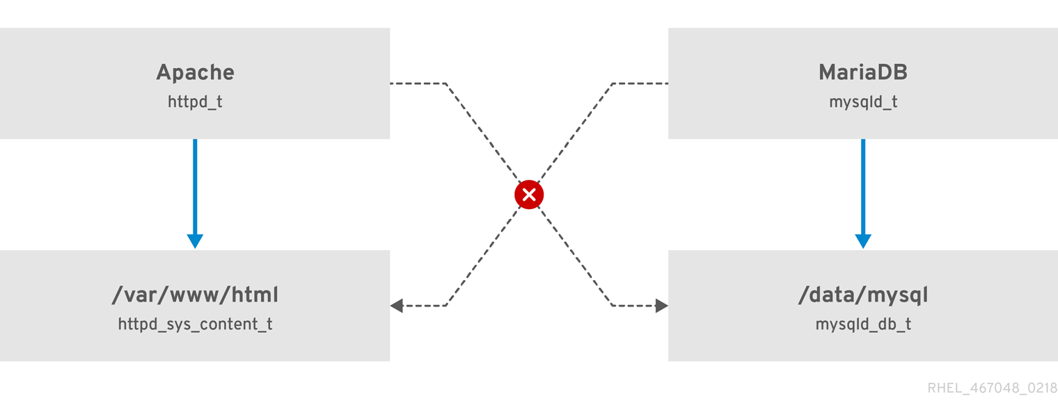
As the previous scheme shows, SELinux allows the Apache process running as httpd_t to access the /var/www/html/ directory and it denies the same process to access the /data/mysql/ directory because there is no allow rule for the httpd_t and mysqld_db_t type contexts. On the other hand, the MariaDB process running as mysqld_t is able to access the /data/mysql/ directory and SELinux also correctly denies the process with the mysqld_t type to access the /var/www/html/ directory labeled as httpd_sys_content_t.
19.1.2. Benefits of running SELinux
SELinux provides the following benefits:
- All processes and files are labeled. SELinux policy rules define how processes interact with files, as well as how processes interact with each other. Access is only allowed if an SELinux policy rule exists that specifically allows it.
- SELinux provides fine-grained access control. Stepping beyond traditional UNIX permissions that are controlled at user discretion and based on Linux user and group IDs, SELinux access decisions are based on all available information, such as an SELinux user, role, type, and, optionally, a security level.
- SELinux policy is administratively-defined and enforced system-wide.
- SELinux can mitigate privilege escalation attacks. Processes run in domains, and are therefore separated from each other. SELinux policy rules define how processes access files and other processes. If a process is compromised, the attacker only has access to the normal functions of that process, and to files the process has been configured to have access to. For example, if the Apache HTTP Server is compromised, an attacker cannot use that process to read files in user home directories, unless a specific SELinux policy rule was added or configured to allow such access.
- SELinux can enforce data confidentiality and integrity, and can protect processes from untrusted inputs.
SELinux is designed to enhance existing security solutions, not replace antivirus software, secure passwords, firewalls, or other security systems. Even when running SELinux, it is important to continue to follow good security practices, such as keeping software up-to-date, using hard-to-guess passwords, and firewalls.
19.1.3. SELinux examples
The following examples demonstrate how SELinux increases security:
- The default action is deny. If an SELinux policy rule does not exist to allow access, such as for a process opening a file, access is denied.
-
SELinux can confine Linux users. A number of confined SELinux users exist in the SELinux policy. Linux users can be mapped to confined SELinux users to take advantage of the security rules and mechanisms applied to them. For example, mapping a Linux user to the SELinux
user_uuser, results in a Linux user that is not able to run unless configured otherwise set user ID (setuid) applications, such assudoandsu. - Increased process and data separation. The concept of SELinux domains allows defining which processes can access certain files and directories. For example, when running SELinux, unless otherwise configured, an attacker cannot compromise a Samba server, and then use that Samba server as an attack vector to read and write to files used by other processes, such as MariaDB databases.
-
SELinux helps mitigate the damage made by configuration mistakes. Domain Name System (DNS) servers often replicate information between each other in a zone transfer. Attackers can use zone transfers to update DNS servers with false information. When running the Berkeley Internet Name Domain (BIND) as a DNS server in RHEL, even if an administrator forgets to limit which servers can perform a zone transfer, the default SELinux policy prevent updates for zone files [1] that use zone transfers, by the BIND
nameddaemon itself, and by other processes. -
Without SELinux, an attacker can misuse a vulnerability to path traversal on an Apache web server and access files and directories stored on the file system by using special elements such as
../. If an attacker attempts an attack on a server running with SELinux in enforcing mode, SELinux denies access to files that thehttpdprocess must not access. SELinux cannot block this type of attack completely but it effectively mitigates it. -
SELinux in enforcing mode successfully prevents exploitation of kernel NULL pointer dereference operators on non-SMAP platforms (CVE-2019-9213). Attackers use a vulnerability in the
mmapfunction, which does not check mapping of a null page, for placing arbitrary code on this page. -
The
deny_ptraceSELinux boolean and SELinux in enforcing mode protect systems from the PTRACE_TRACEME vulnerability (CVE-2019-13272). Such configuration prevents scenarios when an attacker can getrootprivileges. -
The
nfs_export_all_rwandnfs_export_all_roSELinux booleans provide an easy-to-use tool to prevent misconfigurations of Network File System (NFS) such as accidental sharing/homedirectories.
19.1.4. SELinux architecture and packages
SELinux is a Linux Security Module (LSM) that is built into the Linux kernel. The SELinux subsystem in the kernel is driven by a security policy which is controlled by the administrator and loaded at boot. All security-relevant, kernel-level access operations on the system are intercepted by SELinux and examined in the context of the loaded security policy. If the loaded policy allows the operation, it continues. Otherwise, the operation is blocked and the process receives an error.
SELinux decisions, such as allowing or disallowing access, are cached. This cache is known as the Access Vector Cache (AVC). When using these cached decisions, SELinux policy rules need to be checked less, which increases performance. Remember that SELinux policy rules have no effect if DAC rules deny access first. Raw audit messages are logged to the /var/log/audit/audit.log and they start with the type=AVC string.
In RHEL 8, system services are controlled by the systemd daemon; systemd starts and stops all services, and users and processes communicate with systemd using the systemctl utility. The systemd daemon can consult the SELinux policy and check the label of the calling process and the label of the unit file that the caller tries to manage, and then ask SELinux whether or not the caller is allowed the access. This approach strengthens access control to critical system capabilities, which include starting and stopping system services.
The systemd daemon also works as an SELinux Access Manager. It retrieves the label of the process running systemctl or the process that sent a D-Bus message to systemd. The daemon then looks up the label of the unit file that the process wanted to configure. Finally, systemd can retrieve information from the kernel if the SELinux policy allows the specific access between the process label and the unit file label. This means a compromised application that needs to interact with systemd for a specific service can now be confined by SELinux. Policy writers can also use these fine-grained controls to confine administrators.
If a process is sending a D-Bus message to another process and if the SELinux policy does not allow the D-Bus communication of these two processes, then the system prints a USER_AVC denial message, and the D-Bus communication times out. Note that the D-Bus communication between two processes works bidirectionally.
To avoid incorrect SELinux labeling and subsequent problems, ensure that you start services using a systemctl start command.
RHEL 8 provides the following packages for working with SELinux:
-
policies:
selinux-policy-targeted,selinux-policy-mls -
tools:
policycoreutils,policycoreutils-gui,libselinux-utils,policycoreutils-python-utils,setools-console,checkpolicy
19.1.5. SELinux states and modes
SELinux can run in one of three modes: enforcing, permissive, or disabled.
- Enforcing mode is the default, and recommended, mode of operation; in enforcing mode SELinux operates normally, enforcing the loaded security policy on the entire system.
- In permissive mode, the system acts as if SELinux is enforcing the loaded security policy, including labeling objects and emitting access denial entries in the logs, but it does not actually deny any operations. While not recommended for production systems, permissive mode can be helpful for SELinux policy development and debugging.
- Disabled mode is strongly discouraged; not only does the system avoid enforcing the SELinux policy, it also avoids labeling any persistent objects such as files, making it difficult to enable SELinux in the future.
Use the setenforce utility to change between enforcing and permissive mode. Changes made with setenforce do not persist across reboots. To change to enforcing mode, enter the setenforce 1 command as the Linux root user. To change to permissive mode, enter the setenforce 0 command. Use the getenforce utility to view the current SELinux mode:
# getenforce
Enforcing# setenforce 0
# getenforce
Permissive# setenforce 1
# getenforce
EnforcingIn Red Hat Enterprise Linux, you can set individual domains to permissive mode while the system runs in enforcing mode. For example, to make the httpd_t domain permissive:
# semanage permissive -a httpd_tNote that permissive domains are a powerful tool that can compromise security of your system. Red Hat recommends to use permissive domains with caution, for example, when debugging a specific scenario.
19.2. Changing SELinux states and modes
When enabled, SELinux can run in one of two modes: enforcing or permissive. The following sections show how to permanently change into these modes.
19.2.1. Permanent changes in SELinux states and modes
As discussed in SELinux states and modes, SELinux can be enabled or disabled. When enabled, SELinux has two modes: enforcing and permissive.
Use the getenforce or sestatus commands to check in which mode SELinux is running. The getenforce command returns Enforcing, Permissive, or Disabled.
The sestatus command returns the SELinux status and the SELinux policy being used:
$ sestatus
SELinux status: enabled
SELinuxfs mount: /sys/fs/selinux
SELinux root directory: /etc/selinux
Loaded policy name: targeted
Current mode: enforcing
Mode from config file: enforcing
Policy MLS status: enabled
Policy deny_unknown status: allowed
Memory protection checking: actual (secure)
Max kernel policy version: 31When systems run SELinux in permissive mode, users and processes might label various file-system objects incorrectly. File-system objects created while SELinux is disabled are not labeled at all. This behavior causes problems when changing to enforcing mode because SELinux relies on correct labels of file-system objects.
To prevent incorrectly labeled and unlabeled files from causing problems, SELinux automatically relabels file systems when changing from the disabled state to permissive or enforcing mode. Use the fixfiles -F onboot command as root to create the /.autorelabel file containing the -F option to ensure that files are relabeled upon next reboot.
Before rebooting the system for relabeling, make sure the system will boot in permissive mode, for example by using the enforcing=0 kernel option. This prevents the system from failing to boot in case the system contains unlabeled files required by systemd before launching the selinux-autorelabel service. For more information, see RHBZ#2021835.
19.2.2. Changing SELinux to permissive mode
When SELinux is running in permissive mode, SELinux policy is not enforced. The system remains operational and SELinux does not deny any operations but only logs AVC messages, which can be then used for troubleshooting, debugging, and SELinux policy improvements. Each AVC is logged only once in this case.
Prerequisites
-
The
selinux-policy-targeted,libselinux-utils, andpolicycoreutilspackages are installed on your system. -
The
selinux=0orenforcing=0kernel parameters are not used.
Procedure
Open the
/etc/selinux/configfile in a text editor of your choice, for example:# vi /etc/selinux/configConfigure the
SELINUX=permissiveoption:# This file controls the state of SELinux on the system. # SELINUX= can take one of these three values: # enforcing - SELinux security policy is enforced. # permissive - SELinux prints warnings instead of enforcing. # disabled - No SELinux policy is loaded. SELINUX=permissive # SELINUXTYPE= can take one of these two values: # targeted - Targeted processes are protected, # mls - Multi Level Security protection. SELINUXTYPE=targetedRestart the system:
# reboot
Verification
After the system restarts, confirm that the
getenforcecommand returnsPermissive:$ getenforce Permissive
19.2.3. Changing SELinux to enforcing mode
When SELinux is running in enforcing mode, it enforces the SELinux policy and denies access based on SELinux policy rules. In RHEL, enforcing mode is enabled by default when the system was initially installed with SELinux.
Prerequisites
-
The
selinux-policy-targeted,libselinux-utils, andpolicycoreutilspackages are installed on your system. -
The
selinux=0orenforcing=0kernel parameters are not used.
Procedure
Open the
/etc/selinux/configfile in a text editor of your choice, for example:# vi /etc/selinux/configConfigure the
SELINUX=enforcingoption:# This file controls the state of SELinux on the system. # SELINUX= can take one of these three values: # enforcing - SELinux security policy is enforced. # permissive - SELinux prints warnings instead of enforcing. # disabled - No SELinux policy is loaded. SELINUX=enforcing # SELINUXTYPE= can take one of these two values: # targeted - Targeted processes are protected, # mls - Multi Level Security protection. SELINUXTYPE=targetedSave the change, and restart the system:
# rebootOn the next boot, SELinux relabels all the files and directories within the system and adds SELinux context for files and directories that were created when SELinux was disabled.
Verification
After the system restarts, confirm that the
getenforcecommand returnsEnforcing:$ getenforce Enforcing
Troubleshooting
After changing to enforcing mode, SELinux may deny some actions because of incorrect or missing SELinux policy rules.
To view what actions SELinux denies, enter the following command as root:
# ausearch -m AVC,USER_AVC,SELINUX_ERR,USER_SELINUX_ERR -ts todayAlternatively, with the
setroubleshoot-serverpackage installed, enter:# grep "SELinux is preventing" /var/log/messagesIf SELinux is active and the Audit daemon (
auditd) is not running on your system, then search for certain SELinux messages in the output of thedmesgcommand:# dmesg | grep -i -e type=1300 -e type=1400
See Troubleshooting problems related to SELinux for more information.
19.2.4. Enabling SELinux on systems that previously had it disabled
To avoid problems, such as systems unable to boot or process failures, when enabling SELinux on systems that previously had it disabled, resolve Access Vector Cache (AVC) messages in permissive mode first.
When systems run SELinux in permissive mode, users and processes might label various file-system objects incorrectly. File-system objects created while SELinux is disabled are not labeled at all. This behavior causes problems when changing to enforcing mode because SELinux relies on correct labels of file-system objects.
To prevent incorrectly labeled and unlabeled files from causing problems, SELinux automatically relabels file systems when changing from the disabled state to permissive or enforcing mode.
Before rebooting the system for relabeling, make sure the system will boot in permissive mode, for example by using the enforcing=0 kernel option. This prevents the system from failing to boot in case the system contains unlabeled files required by systemd before launching the selinux-autorelabel service. For more information, see RHBZ#2021835.
Procedure
- Enable SELinux in permissive mode. For more information, see Changing to permissive mode.
Restart your system:
# reboot- Check for SELinux denial messages. For more information, see Identifying SELinux denials.
Ensure that files are relabeled upon the next reboot:
# fixfiles -F onbootThis creates the
/.autorelabelfile containing the-Foption.WarningAlways switch to permissive mode before entering the
fixfiles -F onbootcommand.By default,
autorelabeluses as many threads in parallel as the system has available CPU cores. To use only a single thread during automatic relabeling, use thefixfiles -T 1 onbootcommand.- If there are no denials, switch to enforcing mode. For more information, see Changing SELinux modes at boot time.
Verification
After the system restarts, confirm that the
getenforcecommand returnsEnforcing:$ getenforce Enforcing
Next steps
To run custom applications with SELinux in enforcing mode, choose one of the following scenarios:
-
Run your application in the
unconfined_service_tdomain. - Write a new policy for your application. See the Writing a custom SELinux policy section for more information.
19.2.5. Disabling SELinux
When you disable SELinux, your system does not load your SELinux policy. As a result, the system does not enforce the SELinux policy and does not log Access Vector Cache (AVC) messages. Therefore, all benefits of running SELinux are lost.
Do not disable SELinux except in specific scenarios, such as performance-sensitive systems where the weakened security does not impose significant risks.
If your scenario requires to perform debugging in a production environment, temporarily use permissive mode instead of permanently disabling SELinux. See Changing to permissive mode for more information about permissive mode.
Prerequisites
The
grubbypackage is installed:$ rpm -q grubby grubby-<version>
Procedure
Configure your boot loader to add
selinux=0to the kernel command line:$ sudo grubby --update-kernel ALL --args selinux=0Restart your system:
$ reboot
Verification
After the reboot, confirm that the
getenforcecommand returnsDisabled:$ getenforce Disabled
Alternative method
In RHEL 8, you can still use the deprecated method for disabling SELinux by using the SELINUX=disabled option in the /etc/selinux/config file. This results the kernel booting with SELinux enabled and switching to disabled mode later in the boot process. Consequently, memory leaks and race conditions might occur that cause kernel panics. To use this method:
Open the
/etc/selinux/configfile in a text editor of your choice, for example:# vi /etc/selinux/configConfigure the
SELINUX=disabledoption:# This file controls the state of SELinux on the system. # SELINUX= can take one of these three values: # enforcing - SELinux security policy is enforced. # permissive - SELinux prints warnings instead of enforcing. # disabled - No SELinux policy is loaded. SELINUX=disabled # SELINUXTYPE= can take one of these two values: # targeted - Targeted processes are protected, # mls - Multi Level Security protection. SELINUXTYPE=targetedSave the change, and restart your system:
# reboot
19.2.6. Changing SELinux modes at boot time
On boot, you can set the following kernel parameters to change the way SELinux runs:
enforcing=0Setting this parameter causes the system to start in permissive mode, which is useful when troubleshooting issues. Using permissive mode might be the only option to detect a problem if your file system is too corrupted. Moreover, in permissive mode, the system continues to create the labels correctly. The AVC messages that are created in this mode can be different than in enforcing mode.
In permissive mode, only the first denial from a series of the same denials is reported. However, in enforcing mode, you might get a denial related to reading a directory, and an application stops. In permissive mode, you get the same AVC message, but the application continues reading files in the directory and you get an AVC for each denial in addition.
selinux=0This parameter causes the kernel to not load any part of the SELinux infrastructure. The init scripts notice that the system booted with the
selinux=0parameter and touch the/.autorelabelfile. This causes the system to automatically relabel the next time you boot with SELinux enabled.ImportantDo not use the
selinux=0parameter in a production environment. To debug your system, temporarily use permissive mode instead of disabling SELinux.autorelabel=1This parameter forces the system to relabel similarly to the following commands:
# touch /.autorelabel # rebootIf a file system contains a large amount of mislabeled objects, start the system in permissive mode to make the autorelabel process successful.
Part III. Design of network
Chapter 20. Configuring ip networking with ifcfg files
Interface configuration (ifcfg) files control the software interfaces for individual network devices. As the system boots, it uses these files to determine what interfaces to bring up and how to configure them. These files are named ifcfg-name_pass, where the suffix name refers to the name of the device that the configuration file controls. By convention, the ifcfg file’s suffix is the same as the string given by the DEVICE directive in the configuration file itself.
NetworkManager supports profiles stored in the keyfile format. However, by default, NetworkManager uses the ifcfg format when you use the NetworkManager API to create or update profiles.
In a future major RHEL release, the keyfile format will be default. Consider using the keyfile format if you want to manually create and manage configuration files. For details, see NetworkManager connection profiles in keyfile format.
20.1. Configuring an interface with static network settings using ifcfg files
If you do not use the NetworkManager utilities and applications, you can manually configure a network interface by creating ifcfg files.
Procedure
To configure an interface with static network settings using
ifcfgfiles, for an interface with the nameenp1s0, create a file with the nameifcfg-enp1s0in the/etc/sysconfig/network-scripts/directory that contains:For
IPv4configuration:DEVICE=enp1s0 BOOTPROTO=none ONBOOT=yes PREFIX=24 IPADDR=192.0.2.1 GATEWAY=192.0.2.254For
IPv6configuration:DEVICE=enp1s0 BOOTPROTO=none ONBOOT=yes IPV6INIT=yes IPV6ADDR=2001:db8:1::2/64
20.2. Configuring an interface with dynamic network settings using ifcfg files
If you do not use the NetworkManager utilities and applications, you can manually configure a network interface by creating ifcfg files.
Procedure
To configure an interface named em1 with dynamic network settings using
ifcfgfiles, create a file with the nameifcfg-em1in the/etc/sysconfig/network-scripts/directory that contains:DEVICE=em1 BOOTPROTO=dhcp ONBOOT=yesTo configure an interface to send:
A different host name to the
DHCPserver, add the following line to theifcfgfile:DHCP_HOSTNAME=hostnameA different fully qualified domain name (FQDN) to the
DHCPserver, add the following line to theifcfgfile:DHCP_FQDN=fully.qualified.domain.name
NoteYou can use only one of these settings. If you specify both
DHCP_HOSTNAMEandDHCP_FQDN, onlyDHCP_FQDNis used.To configure an interface to use particular
DNSservers, add the following lines to theifcfgfile:PEERDNS=no DNS1=ip-address DNS2=ip-addresswhere ip-address is the address of a
DNSserver. This will cause the network service to update/etc/resolv.confwith the specifiedDNSservers specified. Only oneDNSserver address is necessary, the other is optional.
20.3. Managing system-wide and private connection profiles with ifcfg files
By default, all users on a host can use the connections defined in ifcfg files. You can limit this behavior to specific users by adding the USERS parameter to the ifcfg file.
Prerequisites
-
The
ifcfgfile already exists.
Procedure
Edit the
ifcfgfile in the/etc/sysconfig/network-scripts/directory that you want to limit to certain users, and add:USERS="username1 username2 ..."Reactive the connection:
# nmcli connection up connection_name
Chapter 21. Getting started with IPVLAN
IPVLAN is a driver for a virtual network device that can be used in container environment to access the host network. IPVLAN exposes a single MAC address to the external network regardless the number of IPVLAN device created inside the host network. This means that a user can have multiple IPVLAN devices in multiple containers and the corresponding switch reads a single MAC address. IPVLAN driver is useful when the local switch imposes constraints on the total number of MAC addresses that it can manage.
21.1. IPVLAN modes
The following modes are available for IPVLAN:
L2 mode
In IPVLAN L2 mode, virtual devices receive and respond to address resolution protocol (ARP) requests. The
netfilterframework runs only inside the container that owns the virtual device. Nonetfilterchains are executed in the default namespace on the containerized traffic. Using L2 mode provides good performance, but less control on the network traffic.L3 mode
In L3 mode, virtual devices process only L3 traffic and above. Virtual devices do not respond to ARP request and users must configure the neighbour entries for the IPVLAN IP addresses on the relevant peers manually. The egress traffic of a relevant container is landed on the
netfilterPOSTROUTING and OUTPUT chains in the default namespace while the ingress traffic is threaded in the same way as L2 mode. Using L3 mode provides good control but decreases the network traffic performance.L3S mode
In L3S mode, virtual devices process the same way as in L3 mode, except that both egress and ingress traffics of a relevant container are landed on
netfilterchain in the default namespace. L3S mode behaves in a similar way to L3 mode but provides greater control of the network.
The IPVLAN virtual device does not receive broadcast and multicast traffic in case of L3 and L3S modes.
21.2. Comparison of IPVLAN and MACVLAN
The following table shows the major differences between MACVLAN and IPVLAN:
| MACVLAN | IPVLAN |
|---|---|
| Uses MAC address for each MACVLAN device. Note that, if a switch reaches the maximum number of MAC addresses it can store in its MAC table, connectivity can be lost. | Uses single MAC address which does not limit the number of IPVLAN devices. |
| Netfilter rules for a global namespace cannot affect traffic to or from a MACVLAN device in a child namespace. | It is possible to control traffic to or from a IPVLAN device in L3 mode and L3S mode. |
Both IPVLAN and MACVLAN do not require any level of encapsulation.
21.3. Creating and configuring the IPVLAN device using iproute2
This procedure shows how to set up the IPVLAN device using iproute2.
Procedure
To create an IPVLAN device, enter the following command:
# ip link add link real_NIC_device name IPVLAN_device type ipvlan mode l2Note that network interface controller (NIC) is a hardware component which connects a computer to a network.
Example 21.1. Creating an IPVLAN device
# ip link add link enp0s31f6 name my_ipvlan type ipvlan mode l2 # ip link 47: my_ipvlan@enp0s31f6: <BROADCAST,MULTICAST> mtu 1500 qdisc noop state DOWN mode DEFAULT group default qlen 1000 link/ether e8:6a:6e:8a:a2:44 brd ff:ff:ff:ff:ff:ffTo assign an
IPv4orIPv6address to the interface, enter the following command:# ip addr add dev IPVLAN_device IP_address/subnet_mask_prefixIn case of configuring an IPVLAN device in L3 mode or L3S mode, make the following setups:
Configure the neighbor setup for the remote peer on the remote host:
# ip neigh add dev peer_device IPVLAN_device_IP_address lladdr MAC_addresswhere MAC_address is the MAC address of the real NIC on which an IPVLAN device is based on.
Configure an IPVLAN device for L3 mode with the following command:
# ip route add dev <real_NIC_device> <peer_IP_address/32>For L3S mode:
# ip route add dev real_NIC_device peer_IP_address/32where IP-address represents the address of the remote peer.
To set an IPVLAN device active, enter the following command:
# ip link set dev IPVLAN_device upTo check if the IPVLAN device is active, execute the following command on the remote host:
# ping IP_addresswhere the IP_address uses the IP address of the IPVLAN device.
Chapter 22. Reusing the same IP address on different interfaces
With Virtual routing and forwarding (VRF), administrators can use multiple routing tables simultaneously on the same host. For that, VRF partitions a network at layer 3. This enables the administrator to isolate traffic using separate and independent route tables per VRF domain. This technique is similar to virtual LANs (VLAN), which partitions a network at layer 2, where the operating system uses different VLAN tags to isolate traffic sharing the same physical medium.
One benefit of VRF over partitioning on layer 2 is that routing scales better considering the number of peers involved.
Red Hat Enterprise Linux uses a virtual vrt device for each VRF domain and adds routes to a VRF domain by adding existing network devices to a VRF device. Addresses and routes previously attached to the original device will be moved inside the VRF domain.
Note that each VRF domain is isolated from each other.
22.1. Permanently reusing the same IP address on different interfaces
You can use the virtual routing and forwarding (VRF) feature to permanently use the same IP address on different interfaces in one server.
To enable remote peers to contact both VRF interfaces while reusing the same IP address, the network interfaces must belong to different broadcasting domains. A broadcast domain in a network is a set of nodes, which receive broadcast traffic sent by any of them. In most configurations, all nodes connected to the same switch belong to the same broadcasting domain.
Prerequisites
-
You are logged in as the
rootuser. - The network interfaces are not configured.
Procedure
Create and configure the first VRF device:
Create a connection for the VRF device and assign it to a routing table. For example, to create a VRF device named
vrf0that is assigned to the1001routing table:# nmcli connection add type vrf ifname vrf0 con-name vrf0 table 1001 ipv4.method disabled ipv6.method disabledEnable the
vrf0device:# nmcli connection up vrf0Assign a network device to the VRF just created. For example, to add the
enp1s0Ethernet device to thevrf0VRF device and assign an IP address and the subnet mask toenp1s0, enter:# nmcli connection add type ethernet con-name vrf.enp1s0 ifname enp1s0 master vrf0 ipv4.method manual ipv4.address 192.0.2.1/24Activate the
vrf.enp1s0connection:# nmcli connection up vrf.enp1s0
Create and configure the next VRF device:
Create the VRF device and assign it to a routing table. For example, to create a VRF device named
vrf1that is assigned to the1002routing table, enter:# nmcli connection add type vrf ifname vrf1 con-name vrf1 table 1002 ipv4.method disabled ipv6.method disabledActivate the
vrf1device:# nmcli connection up vrf1Assign a network device to the VRF just created. For example, to add the
enp7s0Ethernet device to thevrf1VRF device and assign an IP address and the subnet mask toenp7s0, enter:# nmcli connection add type ethernet con-name vrf.enp7s0 ifname enp7s0 master vrf1 ipv4.method manual ipv4.address 192.0.2.1/24Activate the
vrf.enp7s0device:# nmcli connection up vrf.enp7s0
22.2. Temporarily reusing the same IP address on different interfaces
You can use the virtual routing and forwarding (VRF) feature to temporarily use the same IP address on different interfaces in one server. Use this procedure only for testing purposes, because the configuration is temporary and lost after you reboot the system.
To enable remote peers to contact both VRF interfaces while reusing the same IP address, the network interfaces must belong to different broadcasting domains. A broadcast domain in a network is a set of nodes which receive broadcast traffic sent by any of them. In most configurations, all nodes connected to the same switch belong to the same broadcasting domain.
Prerequisites
-
You are logged in as the
rootuser. - The network interfaces are not configured.
Procedure
Create and configure the first VRF device:
Create the VRF device and assign it to a routing table. For example, to create a VRF device named
bluethat is assigned to the1001routing table:# ip link add dev blue type vrf table 1001Enable the
bluedevice:# ip link set dev blue upAssign a network device to the VRF device. For example, to add the
enp1s0Ethernet device to theblueVRF device:# ip link set dev enp1s0 master blueEnable the
enp1s0device:# ip link set dev enp1s0 upAssign an IP address and subnet mask to the
enp1s0device. For example, to set it to192.0.2.1/24:# ip addr add dev enp1s0 192.0.2.1/24
Create and configure the next VRF device:
Create the VRF device and assign it to a routing table. For example, to create a VRF device named
redthat is assigned to the1002routing table:# ip link add dev red type vrf table 1002Enable the
reddevice:# ip link set dev red upAssign a network device to the VRF device. For example, to add the
enp7s0Ethernet device to theredVRF device:# ip link set dev enp7s0 master redEnable the
enp7s0device:# ip link set dev enp7s0 upAssign the same IP address and subnet mask to the
enp7s0device as you used forenp1s0in theblueVRF domain:# ip addr add dev enp7s0 192.0.2.1/24
- Optional: Create further VRF devices as described above.
Chapter 23. Securing networks
23.1. Using secure communications between two systems with OpenSSH
SSH (Secure Shell) is a protocol which provides secure communications between two systems using a client-server architecture and allows users to log in to server host systems remotely. Unlike other remote communication protocols, such as FTP or Telnet, SSH encrypts the login session, which prevents intruders from collecting unencrypted passwords from the connection.
23.1.1. Generating SSH key pairs
You can log in to an OpenSSH server without entering a password by generating an SSH key pair on a local system and copying the generated public key to the OpenSSH server. Each user who wants to create a key must run this procedure.
To preserve previously generated key pairs after you reinstall the system, back up the ~/.ssh/ directory before you create new keys. After reinstalling, copy it back to your home directory. You can do this for all users on your system, including root.
Prerequisites
- You are logged in as a user who wants to connect to the OpenSSH server by using keys.
- The OpenSSH server is configured to allow key-based authentication.
Procedure
Generate an ECDSA key pair:
$ ssh-keygen -t ecdsa Generating public/private ecdsa key pair. Enter file in which to save the key (/home/<username>/.ssh/id_ecdsa): Enter passphrase (empty for no passphrase): <password> Enter same passphrase again: <password> Your identification has been saved in /home/<username>/.ssh/id_ecdsa. Your public key has been saved in /home/<username>/.ssh/id_ecdsa.pub. The key fingerprint is: SHA256:Q/x+qms4j7PCQ0qFd09iZEFHA+SqwBKRNaU72oZfaCI <username>@<localhost.example.com> The key's randomart image is: +---[ECDSA 256]---+ |.oo..o=++ | |.. o .oo . | |. .. o. o | |....o.+... | |o.oo.o +S . | |.=.+. .o | |E.*+. . . . | |.=..+ +.. o | | . oo*+o. | +----[SHA256]-----+You can also generate an RSA key pair by using the
ssh-keygencommand without any parameter or an Ed25519 key pair by entering thessh-keygen -t ed25519command. Note that the Ed25519 algorithm is not FIPS-140-compliant, and OpenSSH does not work with Ed25519 keys in FIPS mode.Copy the public key to a remote machine:
$ ssh-copy-id <username>@<ssh-server-example.com> /usr/bin/ssh-copy-id: INFO: attempting to log in with the new key(s), to filter out any that are already installed <username>@<ssh-server-example.com>'s password: … Number of key(s) added: 1 Now try logging into the machine, with: "ssh '<username>@<ssh-server-example.com>'" and check to make sure that only the key(s) you wanted were added.Replace
<username>@<ssh-server-example.com>with your credentials.If you do not use the
ssh-agentprogram in your session, the previous command copies the most recently modified~/.ssh/id*.pubpublic key if it is not yet installed. To specify another public-key file or to prioritize keys in files over keys cached in memory byssh-agent, use thessh-copy-idcommand with the-ioption.
Verification
Log in to the OpenSSH server by using the key file:
$ ssh -o PreferredAuthentications=publickey <username>@<ssh-server-example.com>
23.1.2. Setting key-based authentication as the only method on an OpenSSH server
To improve system security, enforce key-based authentication by disabling password authentication on your OpenSSH server.
Prerequisites
-
The
openssh-serverpackage is installed. -
The
sshddaemon is running on the server. You can already connect to the OpenSSH server by using a key.
See the Generating SSH key pairs section for details.
Procedure
Open the
/etc/ssh/sshd_configconfiguration in a text editor, for example:# vi /etc/ssh/sshd_configChange the
PasswordAuthenticationoption tono:PasswordAuthentication no-
On a system other than a new default installation, check that the
PubkeyAuthenticationparameter is either not set or set toyes. Set the
ChallengeResponseAuthenticationdirective tono.Note that the corresponding entry is commented out in the configuration file and the default value is
yes.To use key-based authentication with NFS-mounted home directories, enable the
use_nfs_home_dirsSELinux boolean:# setsebool -P use_nfs_home_dirs 1- If you are connected remotely, not using console or out-of-band access, test the key-based login process before disabling password authentication.
Reload the
sshddaemon to apply the changes:# systemctl reload sshd
23.1.3. Caching your SSH credentials by using ssh-agent
To avoid entering a passphrase each time you initiate an SSH connection, you can use the ssh-agent utility to cache the private SSH key for a login session. If the agent is running and your keys are unlocked, you can log in to SSH servers by using these keys but without having to enter the key’s password again. The private key and the passphrase remain secure.
Prerequisites
- You have a remote host with the SSH daemon running and reachable through the network.
- You know the IP address or hostname and credentials to log in to the remote host.
You have generated an SSH key pair with a passphrase and transferred the public key to the remote machine.
See the Generating SSH key pairs section for details.
Procedure
Add the command for automatically starting
ssh-agentin your session to the~/.bashrcfile:Open
~/.bashrcin a text editor of your choice, for example:$ vi ~/.bashrcAdd the following line to the file:
eval $(ssh-agent)- Save the changes, and quit the editor.
Add the following line to the
~/.ssh/configfile:AddKeysToAgent yesWith this option and
ssh-agentstarted in your session, the agent prompts for a password only for the first time when you connect to a host.
Verification
Log in to a host which uses the corresponding public key of the cached private key in the agent, for example:
$ ssh <example.user>@<ssh-server@example.com>Note that you did not have to enter the passphrase.
23.1.4. Authenticating by SSH keys stored on a smart card
You can create and store ECDSA and RSA keys on a smart card and authenticate by the smart card on an OpenSSH client. Smart-card authentication replaces the default password authentication.
Prerequisites
-
On the client side, the
openscpackage is installed and thepcscdservice is running.
Procedure
List all keys provided by the OpenSC PKCS #11 module including their PKCS #11 URIs and save the output to the
keys.pubfile:$ ssh-keygen -D pkcs11: > keys.pubTransfer the public key to the remote server. Use the
ssh-copy-idcommand with thekeys.pubfile created in the previous step:$ ssh-copy-id -f -i keys.pub <username@ssh-server-example.com>Connect to <ssh-server-example.com> by using the ECDSA key. You can use just a subset of the URI, which uniquely references your key, for example:
$ ssh -i "pkcs11:id=%01?module-path=/usr/lib64/pkcs11/opensc-pkcs11.so" <ssh-server-example.com> Enter PIN for 'SSH key': [ssh-server-example.com] $Because OpenSSH uses the
p11-kit-proxywrapper and the OpenSC PKCS #11 module is registered to thep11-kittool, you can simplify the previous command:$ ssh -i "pkcs11:id=%01" <ssh-server-example.com> Enter PIN for 'SSH key': [ssh-server-example.com] $If you skip the
id=part of a PKCS #11 URI, OpenSSH loads all keys that are available in the proxy module. This can reduce the amount of typing required:$ ssh -i pkcs11: <ssh-server-example.com> Enter PIN for 'SSH key': [ssh-server-example.com] $Optional: You can use the same URI string in the
~/.ssh/configfile to make the configuration permanent:$ cat ~/.ssh/config IdentityFile "pkcs11:id=%01?module-path=/usr/lib64/pkcs11/opensc-pkcs11.so" $ ssh <ssh-server-example.com> Enter PIN for 'SSH key': [ssh-server-example.com] $The
sshclient utility now automatically uses this URI and the key from the smart card.
23.2. Planning and implementing TLS
TLS (Transport Layer Security) is a cryptographic protocol used to secure network communications. When hardening system security settings by configuring preferred key-exchange protocols, authentication methods, and encryption algorithms, it is necessary to bear in mind that the broader the range of supported clients, the lower the resulting security. Conversely, strict security settings lead to limited compatibility with clients, which can result in some users being locked out of the system. Be sure to target the strictest available configuration and only relax it when it is required for compatibility reasons.
23.2.1. SSL and TLS protocols
The Secure Sockets Layer (SSL) protocol was originally developed by Netscape Corporation to provide a mechanism for secure communication over the Internet. Subsequently, the protocol was adopted by the Internet Engineering Task Force (IETF) and renamed to Transport Layer Security (TLS).
The TLS protocol sits between an application protocol layer and a reliable transport layer, such as TCP/IP. It is independent of the application protocol and can thus be layered underneath many different protocols, for example: HTTP, FTP, SMTP, and so on.
| Protocol version | Usage recommendation |
|---|---|
| SSL v2 | Do not use. Has serious security vulnerabilities. Removed from the core crypto libraries since RHEL 7. |
| SSL v3 | Do not use. Has serious security vulnerabilities. Removed from the core crypto libraries since RHEL 8. |
| TLS 1.0 |
Not recommended to use. Has known issues that cannot be mitigated in a way that guarantees interoperability, and does not support modern cipher suites. In RHEL 8, enabled only in the |
| TLS 1.1 |
Use for interoperability purposes where needed. Does not support modern cipher suites. In RHEL 8, enabled only in the |
| TLS 1.2 | Supports the modern AEAD cipher suites. This version is enabled in all system-wide crypto policies, but optional parts of this protocol contain vulnerabilities and TLS 1.2 also allows outdated algorithms. |
| TLS 1.3 | Recommended version. TLS 1.3 removes known problematic options, provides additional privacy by encrypting more of the negotiation handshake and can be faster thanks usage of more efficient modern cryptographic algorithms. TLS 1.3 is also enabled in all system-wide cryptographic policies. |
23.2.2. Security considerations for TLS in RHEL 8
In RHEL 8, cryptography-related considerations are significantly simplified thanks to the system-wide crypto policies. The DEFAULT crypto policy allows only TLS 1.2 and 1.3. To allow your system to negotiate connections using the earlier versions of TLS, you need to either opt out from following crypto policies in an application or switch to the LEGACY policy with the update-crypto-policies command. See Using system-wide cryptographic policies for more information.
The default settings provided by libraries included in RHEL 8 are secure enough for most deployments. The TLS implementations use secure algorithms where possible while not preventing connections from or to legacy clients or servers. Apply hardened settings in environments with strict security requirements where legacy clients or servers that do not support secure algorithms or protocols are not expected or allowed to connect.
The most straightforward way to harden your TLS configuration is switching the system-wide cryptographic policy level to FUTURE using the update-crypto-policies --set FUTURE command.
Algorithms disabled for the LEGACY cryptographic policy do not conform to Red Hat’s vision of RHEL 8 security, and their security properties are not reliable. Consider moving away from using these algorithms instead of re-enabling them. If you do decide to re-enable them, for example for interoperability with old hardware, treat them as insecure and apply extra protection measures, such as isolating their network interactions to separate network segments. Do not use them across public networks.
If you decide to not follow RHEL system-wide crypto policies or create custom cryptographic policies tailored to your setup, use the following recommendations for preferred protocols, cipher suites, and key lengths on your custom configuration:
23.2.2.1. Protocols
The latest version of TLS provides the best security mechanism. Unless you have a compelling reason to include support for older versions of TLS, allow your systems to negotiate connections using at least TLS version 1.2.
Note that even though RHEL 8 supports TLS version 1.3, not all features of this protocol are fully supported by RHEL 8 components. For example, the 0-RTT (Zero Round Trip Time) feature, which reduces connection latency, is not yet fully supported by the Apache web server.
23.2.2.2. Cipher suites
Modern, more secure cipher suites should be preferred to old, insecure ones. Always disable the use of eNULL and aNULL cipher suites, which do not offer any encryption or authentication at all. If at all possible, ciphers suites based on RC4 or HMAC-MD5, which have serious shortcomings, should also be disabled. The same applies to the so-called export cipher suites, which have been intentionally made weaker, and thus are easy to break.
While not immediately insecure, cipher suites that offer less than 128 bits of security should not be considered for their short useful life. Algorithms that use 128 bits of security or more can be expected to be unbreakable for at least several years, and are thus strongly recommended. Note that while 3DES ciphers advertise the use of 168 bits, they actually offer 112 bits of security.
Always prefer cipher suites that support (perfect) forward secrecy (PFS), which ensures the confidentiality of encrypted data even in case the server key is compromised. This rules out the fast RSA key exchange, but allows for the use of ECDHE and DHE. Of the two, ECDHE is the faster and therefore the preferred choice.
You should also prefer AEAD ciphers, such as AES-GCM, over CBC-mode ciphers as they are not vulnerable to padding oracle attacks. Additionally, in many cases, AES-GCM is faster than AES in CBC mode, especially when the hardware has cryptographic accelerators for AES.
Note also that when using the ECDHE key exchange with ECDSA certificates, the transaction is even faster than a pure RSA key exchange. To provide support for legacy clients, you can install two pairs of certificates and keys on a server: one with ECDSA keys (for new clients) and one with RSA keys (for legacy ones).
23.2.2.3. Public key length
When using RSA keys, always prefer key lengths of at least 3072 bits signed by at least SHA-256, which is sufficiently large for true 128 bits of security.
The security of your system is only as strong as the weakest link in the chain. For example, a strong cipher alone does not guarantee good security. The keys and the certificates are just as important, as well as the hash functions and keys used by the Certification Authority (CA) to sign your keys.
23.2.3. Hardening TLS configuration in applications
In RHEL, system-wide crypto policies provide a convenient way to ensure that your applications that use cryptographic libraries do not allow known insecure protocols, ciphers, or algorithms.
If you want to harden your TLS-related configuration with your customized cryptographic settings, you can use the cryptographic configuration options described in this section, and override the system-wide crypto policies just in the minimum required amount.
Regardless of the configuration you choose to use, always ensure that your server application enforces server-side cipher order, so that the cipher suite to be used is determined by the order you configure.
23.2.3.1. Configuring the Apache HTTP server to use TLS
The Apache HTTP Server can use both OpenSSL and NSS libraries for its TLS needs. RHEL 8 provides the mod_ssl functionality through eponymous packages:
# yum install mod_ssl
The mod_ssl package installs the /etc/httpd/conf.d/ssl.conf configuration file, which can be used to modify the TLS-related settings of the Apache HTTP Server.
Install the httpd-manual package to obtain complete documentation for the Apache HTTP Server, including TLS configuration. The directives available in the /etc/httpd/conf.d/ssl.conf configuration file are described in detail in the /usr/share/httpd/manual/mod/mod_ssl.html file. Examples of various settings are described in the /usr/share/httpd/manual/ssl/ssl_howto.html file.
When modifying the settings in the /etc/httpd/conf.d/ssl.conf configuration file, be sure to consider the following three directives at the minimum:
SSLProtocol- Use this directive to specify the version of TLS or SSL you want to allow.
SSLCipherSuite- Use this directive to specify your preferred cipher suite or disable the ones you want to disallow.
SSLHonorCipherOrder-
Uncomment and set this directive to
onto ensure that the connecting clients adhere to the order of ciphers you specified.
For example, to use only the TLS 1.2 and 1.3 protocol:
SSLProtocol all -SSLv3 -TLSv1 -TLSv1.1See the Configuring TLS encryption on an Apache HTTP Server chapter in the Deploying different types of servers document for more information.
23.2.3.2. Configuring the Nginx HTTP and proxy server to use TLS
To enable TLS 1.3 support in Nginx, add the TLSv1.3 value to the ssl_protocols option in the server section of the /etc/nginx/nginx.conf configuration file:
server {
listen 443 ssl http2;
listen [::]:443 ssl http2;
....
ssl_protocols TLSv1.2 TLSv1.3;
ssl_ciphers
....
}See the Adding TLS encryption to an Nginx web server chapter in the Deploying different types of servers document for more information.
23.2.3.3. Configuring the Dovecot mail server to use TLS
To configure your installation of the Dovecot mail server to use TLS, modify the /etc/dovecot/conf.d/10-ssl.conf configuration file. You can find an explanation of some of the basic configuration directives available in that file in the /usr/share/doc/dovecot/wiki/SSL.DovecotConfiguration.txt file, which is installed along with the standard installation of Dovecot.
When modifying the settings in the /etc/dovecot/conf.d/10-ssl.conf configuration file, be sure to consider the following three directives at the minimum:
ssl_protocols- Use this directive to specify the version of TLS or SSL you want to allow or disable.
ssl_cipher_list- Use this directive to specify your preferred cipher suites or disable the ones you want to disallow.
ssl_prefer_server_ciphers-
Uncomment and set this directive to
yesto ensure that the connecting clients adhere to the order of ciphers you specified.
For example, the following line in /etc/dovecot/conf.d/10-ssl.conf allows only TLS 1.1 and later:
ssl_protocols = !SSLv2 !SSLv3 !TLSv123.3. Setting up an IPsec VPN
A virtual private network (VPN) is a way of connecting to a local network over the internet. IPsec provided by Libreswan is the preferred method for creating a VPN. Libreswan is a user-space IPsec implementation for VPN. A VPN enables the communication between your LAN, and another, remote LAN by setting up a tunnel across an intermediate network such as the internet. For security reasons, a VPN tunnel always uses authentication and encryption. For cryptographic operations, Libreswan uses the NSS library.
23.3.1. Libreswan as an IPsec VPN implementation
In RHEL, you can configure a Virtual Private Network (VPN) by using the IPsec protocol, which is supported by the Libreswan application. Libreswan is a continuation of the Openswan application, and many examples from the Openswan documentation are interchangeable with Libreswan.
The IPsec protocol for a VPN is configured using the Internet Key Exchange (IKE) protocol. The terms IPsec and IKE are used interchangeably. An IPsec VPN is also called an IKE VPN, IKEv2 VPN, XAUTH VPN, Cisco VPN or IKE/IPsec VPN. A variant of an IPsec VPN that also uses the Layer 2 Tunneling Protocol (L2TP) is usually called an L2TP/IPsec VPN, which requires the xl2tpd package provided by the optional repository.
Libreswan is an open-source, user-space IKE implementation. IKE v1 and v2 are implemented as a user-level daemon. The IKE protocol is also encrypted. The IPsec protocol is implemented by the Linux kernel, and Libreswan configures the kernel to add and remove VPN tunnel configurations.
The IKE protocol uses UDP port 500 and 4500. The IPsec protocol consists of two protocols:
- Encapsulated Security Payload (ESP), which has protocol number 50.
- Authenticated Header (AH), which has protocol number 51.
The AH protocol is not recommended for use. Users of AH are recommended to migrate to ESP with null encryption.
The IPsec protocol provides two modes of operation:
- Tunnel Mode (the default)
- Transport Mode
You can configure the kernel with IPsec without IKE. This is called manual keying. You can also configure manual keying using the ip xfrm commands, however, this is strongly discouraged for security reasons. Libreswan communicates with the Linux kernel using the Netlink interface. The kernel performs packet encryption and decryption.
Libreswan uses the Network Security Services (NSS) cryptographic library. NSS is certified for use with the Federal Information Processing Standard (FIPS) Publication 140-2.
IKE/IPsec VPNs, implemented by Libreswan and the Linux kernel, is the only VPN technology recommended for use in RHEL. Do not use any other VPN technology without understanding the risks of doing so.
In RHEL, Libreswan follows system-wide cryptographic policies by default. This ensures that Libreswan uses secure settings for current threat models including IKEv2 as a default protocol. See Using system-wide crypto policies for more information.
Libreswan does not use the terms "source" and "destination" or "server" and "client" because IKE/IPsec are peer to peer protocols. Instead, it uses the terms "left" and "right" to refer to end points (the hosts). This also allows you to use the same configuration on both end points in most cases. However, administrators usually choose to always use "left" for the local host and "right" for the remote host.
The leftid and rightid options serve as identification of the respective hosts in the authentication process. See the ipsec.conf(5) man page for more information.
23.3.2. Authentication methods in Libreswan
Libreswan supports several authentication methods, each of which fits a different scenario.
Pre-Shared key (PSK)
Pre-Shared Key (PSK) is the simplest authentication method. For security reasons, do not use PSKs shorter than 64 random characters. In FIPS mode, PSKs must comply with a minimum-strength requirement depending on the integrity algorithm used. You can set PSK by using the authby=secret connection.
Raw RSA keys
Raw RSA keys are commonly used for static host-to-host or subnet-to-subnet IPsec configurations. Each host is manually configured with the public RSA keys of all other hosts, and Libreswan sets up an IPsec tunnel between each pair of hosts. This method does not scale well for large numbers of hosts.
You can generate a raw RSA key on a host using the ipsec newhostkey command. You can list generated keys by using the ipsec showhostkey command. The leftrsasigkey= line is required for connection configurations that use CKA ID keys. Use the authby=rsasig connection option for raw RSA keys.
X.509 certificates
X.509 certificates are commonly used for large-scale deployments with hosts that connect to a common IPsec gateway. A central certificate authority (CA) signs RSA certificates for hosts or users. This central CA is responsible for relaying trust, including the revocations of individual hosts or users.
For example, you can generate X.509 certificates using the openssl command and the NSS certutil command. Because Libreswan reads user certificates from the NSS database using the certificates' nickname in the leftcert= configuration option, provide a nickname when you create a certificate.
If you use a custom CA certificate, you must import it to the Network Security Services (NSS) database. You can import any certificate in the PKCS #12 format to the Libreswan NSS database by using the ipsec import command.
Libreswan requires an Internet Key Exchange (IKE) peer ID as a subject alternative name (SAN) for every peer certificate as described in section 3.1 of RFC 4945. Disabling this check by setting the require-id-on-certificate=no connection option can make the system vulnerable to man-in-the-middle attacks.
Use the authby=rsasig connection option for authentication based on X.509 certificates using RSA with SHA-1 and SHA-2. You can further limit it for ECDSA digital signatures using SHA-2 by setting authby= to ecdsa and RSA Probabilistic Signature Scheme (RSASSA-PSS) digital signatures based authentication with SHA-2 through authby=rsa-sha2. The default value is authby=rsasig,ecdsa.
The certificates and the authby= signature methods should match. This increases interoperability and preserves authentication in one digital signature system.
NULL authentication
NULL authentication is used to gain mesh encryption without authentication. It protects against passive attacks but not against active attacks. However, because IKEv2 allows asymmetric authentication methods, NULL authentication can also be used for internet-scale opportunistic IPsec. In this model, clients authenticate the server, but servers do not authenticate the client. This model is similar to secure websites using TLS. Use authby=null for NULL authentication.
Protection against quantum computers
In addition to the previously mentioned authentication methods, you can use the Post-quantum Pre-shared Key (PPK) method to protect against possible attacks by quantum computers. Individual clients or groups of clients can use their own PPK by specifying a PPK ID that corresponds to an out-of-band configured pre-shared key.
Using IKEv1 with pre-shared keys protects against quantum attackers. The redesign of IKEv2 does not offer this protection natively. Libreswan offers the use of a Post-quantum Pre-shared Key (PPK) to protect IKEv2 connections against quantum attacks.
To enable optional PPK support, add ppk=yes to the connection definition. To require PPK, add ppk=insist. Then, each client can be given a PPK ID with a secret value that is communicated out-of-band (and preferably quantum-safe). The PPK’s should be very strong in randomness and not based on dictionary words. The PPK ID and PPK data are stored in the ipsec.secrets file, for example:
@west @east : PPKS "user1" "thestringismeanttobearandomstr"
The PPKS option refers to static PPKs. This experimental function uses one-time-pad-based Dynamic PPKs. Upon each connection, a new part of the one-time pad is used as the PPK. When used, that part of the dynamic PPK inside the file is overwritten with zeros to prevent re-use. If there is no more one-time-pad material left, the connection fails. See the ipsec.secrets(5) man page for more information.
The implementation of dynamic PPKs is provided as an unsupported Technology Preview. Use with caution.
23.3.3. Installing Libreswan
Before you can set a VPN through the Libreswan IPsec/IKE implementation, you must install the corresponding packages, start the ipsec service, and allow the service in your firewall.
Prerequisites
-
The
AppStreamrepository is enabled.
Procedure
Install the
libreswanpackages:# yum install libreswanIf you are re-installing Libreswan, remove its old database files and create a new database:
# systemctl stop ipsec # rm /etc/ipsec.d/*db # ipsec initnssStart the
ipsecservice, and enable the service to be started automatically on boot:# systemctl enable ipsec --nowConfigure the firewall to allow 500 and 4500/UDP ports for the IKE, ESP, and AH protocols by adding the
ipsecservice:# firewall-cmd --add-service="ipsec" # firewall-cmd --runtime-to-permanent
23.3.4. Creating a host-to-host VPN
You can configure Libreswan to create a host-to-host IPsec VPN between two hosts referred to as left and right using authentication by raw RSA keys.
Prerequisites
-
Libreswan is installed and the
ipsecservice is started on each node.
Procedure
Generate a raw RSA key pair on each host:
# ipsec newhostkeyThe previous step returned the generated key’s
ckaid. Use thatckaidwith the following command on left, for example:# ipsec showhostkey --left --ckaid 2d3ea57b61c9419dfd6cf43a1eb6cb306c0e857dThe output of the previous command generated the
leftrsasigkey=line required for the configuration. Do the same on the second host (right):# ipsec showhostkey --right --ckaid a9e1f6ce9ecd3608c24e8f701318383f41798f03In the
/etc/ipsec.d/directory, create a newmy_host-to-host.conffile. Write the RSA host keys from the output of theipsec showhostkeycommands in the previous step to the new file. For example:conn mytunnel leftid=@west left=192.1.2.23 leftrsasigkey=0sAQOrlo+hOafUZDlCQmXFrje/oZm [...] W2n417C/4urYHQkCvuIQ== rightid=@east right=192.1.2.45 rightrsasigkey=0sAQO3fwC6nSSGgt64DWiYZzuHbc4 [...] D/v8t5YTQ== authby=rsasigAfter importing keys, restart the
ipsecservice:# systemctl restart ipsecLoad the connection:
# ipsec auto --add mytunnelEstablish the tunnel:
# ipsec auto --up mytunnelTo automatically start the tunnel when the
ipsecservice is started, add the following line to the connection definition:auto=start- If you use this host in a network with DHCP or Stateless Address Autoconfiguration (SLAAC), the connection can be vulnerable to being redirected. For details and mitigation steps, see Assigning a VPN connection to a dedicated routing table to prevent the connection from bypassing the tunnel.
23.3.5. Configuring a site-to-site VPN
To create a site-to-site IPsec VPN, by joining two networks, an IPsec tunnel between the two hosts is created. The hosts thus act as the end points, which are configured to permit traffic from one or more subnets to pass through. Therefore you can think of the host as gateways to the remote portion of the network.
The configuration of the site-to-site VPN only differs from the host-to-host VPN in that one or more networks or subnets must be specified in the configuration file.
Prerequisites
- A host-to-host VPN is already configured.
Procedure
Copy the file with the configuration of your host-to-host VPN to a new file, for example:
# cp /etc/ipsec.d/my_host-to-host.conf /etc/ipsec.d/my_site-to-site.confAdd the subnet configuration to the file created in the previous step, for example:
conn mysubnet also=mytunnel leftsubnet=192.0.1.0/24 rightsubnet=192.0.2.0/24 auto=start conn mysubnet6 also=mytunnel leftsubnet=2001:db8:0:1::/64 rightsubnet=2001:db8:0:2::/64 auto=start # the following part of the configuration file is the same for both host-to-host and site-to-site connections: conn mytunnel leftid=@west left=192.1.2.23 leftrsasigkey=0sAQOrlo+hOafUZDlCQmXFrje/oZm [...] W2n417C/4urYHQkCvuIQ== rightid=@east right=192.1.2.45 rightrsasigkey=0sAQO3fwC6nSSGgt64DWiYZzuHbc4 [...] D/v8t5YTQ== authby=rsasig- If you use this host in a network with DHCP or Stateless Address Autoconfiguration (SLAAC), the connection can be vulnerable to being redirected. For details and mitigation steps, see Assigning a VPN connection to a dedicated routing table to prevent the connection from bypassing the tunnel.
23.3.6. Configuring a remote access VPN
Road warriors are traveling users with mobile clients and a dynamically assigned IP address. The mobile clients authenticate using X.509 certificates.
The following example shows configuration for IKEv2, and it avoids using the IKEv1 XAUTH protocol.
On the server:
conn roadwarriors
ikev2=insist
# support (roaming) MOBIKE clients (RFC 4555)
mobike=yes
fragmentation=yes
left=1.2.3.4
# if access to the LAN is given, enable this, otherwise use 0.0.0.0/0
# leftsubnet=10.10.0.0/16
leftsubnet=0.0.0.0/0
leftcert=gw.example.com
leftid=%fromcert
leftxauthserver=yes
leftmodecfgserver=yes
right=%any
# trust our own Certificate Agency
rightca=%same
# pick an IP address pool to assign to remote users
# 100.64.0.0/16 prevents RFC1918 clashes when remote users are behind NAT
rightaddresspool=100.64.13.100-100.64.13.254
# if you want remote clients to use some local DNS zones and servers
modecfgdns="1.2.3.4, 5.6.7.8"
modecfgdomains="internal.company.com, corp"
rightxauthclient=yes
rightmodecfgclient=yes
authby=rsasig
# optionally, run the client X.509 ID through pam to allow or deny client
# pam-authorize=yes
# load connection, do not initiate
auto=add
# kill vanished roadwarriors
dpddelay=1m
dpdtimeout=5m
dpdaction=clearOn the mobile client, the road warrior’s device, use a slight variation of the previous configuration:
conn to-vpn-server
ikev2=insist
# pick up our dynamic IP
left=%defaultroute
leftsubnet=0.0.0.0/0
leftcert=myname.example.com
leftid=%fromcert
leftmodecfgclient=yes
# right can also be a DNS hostname
right=1.2.3.4
# if access to the remote LAN is required, enable this, otherwise use 0.0.0.0/0
# rightsubnet=10.10.0.0/16
rightsubnet=0.0.0.0/0
fragmentation=yes
# trust our own Certificate Agency
rightca=%same
authby=rsasig
# allow narrowing to the server’s suggested assigned IP and remote subnet
narrowing=yes
# support (roaming) MOBIKE clients (RFC 4555)
mobike=yes
# initiate connection
auto=startIf you use this host in a network with DHCP or Stateless Address Autoconfiguration (SLAAC), the connection can be vulnerable to being redirected. For details and mitigation steps, see Assigning a VPN connection to a dedicated routing table to prevent the connection from bypassing the tunnel.
23.3.7. Configuring a mesh VPN
A mesh VPN network, which is also known as an any-to-any VPN, is a network where all nodes communicate using IPsec. The configuration allows for exceptions for nodes that cannot use IPsec. The mesh VPN network can be configured in two ways:
- To require IPsec.
- To prefer IPsec but allow a fallback to clear-text communication.
Authentication between the nodes can be based on X.509 certificates or on DNS Security Extensions (DNSSEC).
You can use any regular IKEv2 authentication method for opportunistic IPsec, because these connections are regular Libreswan configurations, except for the opportunistic IPsec that is defined by right=%opportunisticgroup entry. A common authentication method is for hosts to authenticate each other based on X.509 certificates using a commonly shared certification authority (CA). Cloud deployments typically issue certificates for each node in the cloud as part of the standard procedure.
Do not use PreSharedKey (PSK) authentication because one compromised host would result in the group PSK secret being compromised as well.
You can use NULL authentication to deploy encryption between nodes without authentication, which protects only against passive attackers.
The following procedure uses X.509 certificates. You can generate these certificates by using any kind of CA management system, such as the Dogtag Certificate System. Dogtag assumes that the certificates for each node are available in the PKCS #12 format (.p12 files), which contain the private key, the node certificate, and the Root CA certificate used to validate other nodes' X.509 certificates.
Each node has an identical configuration with the exception of its X.509 certificate. This allows for adding new nodes without reconfiguring any of the existing nodes in the network. The PKCS #12 files require a "friendly name", for which we use the name "node" so that the configuration files referencing the friendly name can be identical for all nodes.
Prerequisites
-
Libreswan is installed, and the
ipsecservice is started on each node. A new NSS database is initialized.
If you already have an old NSS database, remove the old database files:
# systemctl stop ipsec # rm /etc/ipsec.d/*dbYou can initialize a new database with the following command:
# ipsec initnss
Procedure
On each node, import PKCS #12 files. This step requires the password used to generate the PKCS #12 files:
# ipsec import nodeXXX.p12Create the following three connection definitions for the
IPsec required(private),IPsec optional(private-or-clear), andNo IPsec(clear) profiles:# cat /etc/ipsec.d/mesh.conf conn clear auto=ondemand1 type=passthrough authby=never left=%defaultroute right=%group conn private auto=ondemand type=transport authby=rsasig failureshunt=drop negotiationshunt=drop ikev2=insist left=%defaultroute leftcert=nodeXXXX leftid=%fromcert2 rightid=%fromcert right=%opportunisticgroup conn private-or-clear auto=ondemand type=transport authby=rsasig failureshunt=passthrough negotiationshunt=passthrough # left left=%defaultroute leftcert=nodeXXXX3 leftid=%fromcert leftrsasigkey=%cert # right rightrsasigkey=%cert rightid=%fromcert right=%opportunisticgroup- 1
- The
autovariable has several options:You can use the
ondemandconnection option with opportunistic IPsec to initiate the IPsec connection, or for explicitly configured connections that do not need to be active all the time. This option sets up a trap XFRM policy in the kernel, enabling the IPsec connection to begin when it receives the first packet that matches that policy.You can effectively configure and manage your IPsec connections, whether you use Opportunistic IPsec or explicitly configured connections, by using the following options:
- The
addoption -
Loads the connection configuration and prepares it for responding to remote initiations. However, the connection is not automatically initiated from the local side. You can manually start the IPsec connection by using the command
ipsec auto --up. - The
startoption - Loads the connection configuration and prepares it for responding to remote initiations. Additionally, it immediately initiates a connection to the remote peer. You can use this option for permanent and always active connections.
- The
- 2
- The
leftidandrightidvariables identify the right and the left channel of the IPsec tunnel connection. You can use these variables to obtain the value of the local IP address or the subject DN of the local certificate, if you have configured one. - 3
- The
leftcertvariable defines the nickname of the NSS database that you want to use.
Add the IP address of the network to the corresponding category. For example, if all nodes reside in the
10.15.0.0/16network, and all nodes must use IPsec encryption:# echo "10.15.0.0/16" >> /etc/ipsec.d/policies/privateTo allow certain nodes, for example,
10.15.34.0/24, to work with and without IPsec, add those nodes to the private-or-clear group:# echo "10.15.34.0/24" >> /etc/ipsec.d/policies/private-or-clearTo define a host, for example,
10.15.1.2, which is not capable of IPsec into the clear group, use:# echo "10.15.1.2/32" >> /etc/ipsec.d/policies/clearYou can create the files in the
/etc/ipsec.d/policiesdirectory from a template for each new node, or you can provision them by using Puppet or Ansible.Note that every node has the same list of exceptions or different traffic flow expectations. Two nodes, therefore, might not be able to communicate because one requires IPsec and the other cannot use IPsec.
Restart the node to add it to the configured mesh:
# systemctl restart ipsec- If you use this host in a network with DHCP or Stateless Address Autoconfiguration (SLAAC), the connection can be vulnerable to being redirected. For details and mitigation steps, see Assigning a VPN connection to a dedicated routing table to prevent the connection from bypassing the tunnel.
Verification
Open an IPsec tunnel by using the
pingcommand:# ping <nodeYYY>Display the NSS database with the imported certification:
# certutil -L -d sql:/etc/ipsec.d Certificate Nickname Trust Attributes SSL,S/MIME,JAR/XPI west u,u,u ca CT,,See which tunnels are open on the node:
# ipsec trafficstatus 006 #2: "private#10.15.0.0/16"[1] ...<nodeYYY>, type=ESP, add_time=1691399301, inBytes=512, outBytes=512, maxBytes=2^63B, id='C=US, ST=NC, O=Example Organization, CN=east'
23.3.8. Deploying a FIPS-compliant IPsec VPN
You can deploy a FIPS-compliant IPsec VPN solution with Libreswan. To do so, you can identify which cryptographic algorithms are available and which are disabled for Libreswan in FIPS mode.
Prerequisites
-
The
AppStreamrepository is enabled.
Procedure
Install the
libreswanpackages:# yum install libreswanIf you are re-installing Libreswan, remove its old NSS database:
# systemctl stop ipsec # rm /etc/ipsec.d/*dbStart the
ipsecservice, and enable the service to be started automatically on boot:# systemctl enable ipsec --nowConfigure the firewall to allow
500and4500UDP ports for the IKE, ESP, and AH protocols by adding theipsecservice:# firewall-cmd --add-service="ipsec" # firewall-cmd --runtime-to-permanentSwitch the system to FIPS mode:
# fips-mode-setup --enableRestart your system to allow the kernel to switch to FIPS mode:
# reboot
Verification
Confirm Libreswan is running in FIPS mode:
# ipsec whack --fipsstatus 000 FIPS mode enabledAlternatively, check entries for the
ipsecunit in thesystemdjournal:$ journalctl -u ipsec ... Jan 22 11:26:50 localhost.localdomain pluto[3076]: FIPS Product: YES Jan 22 11:26:50 localhost.localdomain pluto[3076]: FIPS Kernel: YES Jan 22 11:26:50 localhost.localdomain pluto[3076]: FIPS Mode: YESTo see the available algorithms in FIPS mode:
# ipsec pluto --selftest 2>&1 | head -11 FIPS Product: YES FIPS Kernel: YES FIPS Mode: YES NSS DB directory: sql:/etc/ipsec.d Initializing NSS Opening NSS database "sql:/etc/ipsec.d" read-only NSS initialized NSS crypto library initialized FIPS HMAC integrity support [enabled] FIPS mode enabled for pluto daemon NSS library is running in FIPS mode FIPS HMAC integrity verification self-test passedTo query disabled algorithms in FIPS mode:
# ipsec pluto --selftest 2>&1 | grep disabled Encryption algorithm CAMELLIA_CTR disabled; not FIPS compliant Encryption algorithm CAMELLIA_CBC disabled; not FIPS compliant Encryption algorithm SERPENT_CBC disabled; not FIPS compliant Encryption algorithm TWOFISH_CBC disabled; not FIPS compliant Encryption algorithm TWOFISH_SSH disabled; not FIPS compliant Encryption algorithm NULL disabled; not FIPS compliant Encryption algorithm CHACHA20_POLY1305 disabled; not FIPS compliant Hash algorithm MD5 disabled; not FIPS compliant PRF algorithm HMAC_MD5 disabled; not FIPS compliant PRF algorithm AES_XCBC disabled; not FIPS compliant Integrity algorithm HMAC_MD5_96 disabled; not FIPS compliant Integrity algorithm HMAC_SHA2_256_TRUNCBUG disabled; not FIPS compliant Integrity algorithm AES_XCBC_96 disabled; not FIPS compliant DH algorithm MODP1024 disabled; not FIPS compliant DH algorithm MODP1536 disabled; not FIPS compliant DH algorithm DH31 disabled; not FIPS compliantTo list all allowed algorithms and ciphers in FIPS mode:
# ipsec pluto --selftest 2>&1 | grep ESP | grep FIPS | sed "s/^.*FIPS//" {256,192,*128} aes_ccm, aes_ccm_c {256,192,*128} aes_ccm_b {256,192,*128} aes_ccm_a [*192] 3des {256,192,*128} aes_gcm, aes_gcm_c {256,192,*128} aes_gcm_b {256,192,*128} aes_gcm_a {256,192,*128} aesctr {256,192,*128} aes {256,192,*128} aes_gmac sha, sha1, sha1_96, hmac_sha1 sha512, sha2_512, sha2_512_256, hmac_sha2_512 sha384, sha2_384, sha2_384_192, hmac_sha2_384 sha2, sha256, sha2_256, sha2_256_128, hmac_sha2_256 aes_cmac null null, dh0 dh14 dh15 dh16 dh17 dh18 ecp_256, ecp256 ecp_384, ecp384 ecp_521, ecp521
23.3.9. Protecting the IPsec NSS database by a password
By default, the IPsec service creates its Network Security Services (NSS) database with an empty password during the first start. To enhance security, you can add password protection.
In the previous releases of RHEL up to version 6.6, you had to protect the IPsec NSS database with a password to meet the FIPS 140-2 requirements because the NSS cryptographic libraries were certified for the FIPS 140-2 Level 2 standard. In RHEL 8, NIST certified NSS to Level 1 of this standard, and this status does not require password protection for the database.
Prerequisites
-
The
/etc/ipsec.d/directory contains NSS database files.
Procedure
Enable password protection for the
NSSdatabase for Libreswan:# certutil -N -d sql:/etc/ipsec.d Enter Password or Pin for "NSS Certificate DB": Enter a password which will be used to encrypt your keys. The password should be at least 8 characters long, and should contain at least one non-alphabetic character. Enter new password:Create the
/etc/ipsec.d/nsspasswordfile that contains the password you have set in the previous step, for example:# cat /etc/ipsec.d/nsspassword NSS Certificate DB:_<password>_The
nsspasswordfile use the following syntax:<token_1>:<password1> <token_2>:<password2>The default NSS software token is
NSS Certificate DB. If your system is running in FIPS mode, the name of the token isNSS FIPS 140-2 Certificate DB.Depending on your scenario, either start or restart the
ipsecservice after you finish thensspasswordfile:# systemctl restart ipsec
Verification
Check that the
ipsecservice is running after you have added a non-empty password to its NSS database:# systemctl status ipsec ● ipsec.service - Internet Key Exchange (IKE) Protocol Daemon for IPsec Loaded: loaded (/usr/lib/systemd/system/ipsec.service; enabled; vendor preset: disable> Active: active (running)...Check that the
Journallog contains entries that confirm a successful initialization:# journalctl -u ipsec ... pluto[6214]: Initializing NSS using read-write database "sql:/etc/ipsec.d" pluto[6214]: NSS Password from file "/etc/ipsec.d/nsspassword" for token "NSS Certificate DB" with length 20 passed to NSS pluto[6214]: NSS crypto library initialized ...
23.3.10. Configuring an IPsec VPN to use TCP
Libreswan supports TCP encapsulation of IKE and IPsec packets as described in RFC 8229. With this feature, you can establish IPsec VPNs on networks that prevent traffic transmitted via UDP and Encapsulating Security Payload (ESP). You can configure VPN servers and clients to use TCP either as a fallback or as the main VPN transport protocol. Because TCP encapsulation has bigger performance costs, use TCP as the main VPN protocol only if UDP is permanently blocked in your scenario.
Prerequisites
- A remote-access VPN is already configured.
Procedure
Add the following option to the
/etc/ipsec.conffile in theconfig setupsection:listen-tcp=yesTo use TCP encapsulation as a fallback option when the first attempt over UDP fails, add the following two options to the client’s connection definition:
enable-tcp=fallback tcp-remoteport=4500Alternatively, if you know that UDP is permanently blocked, use the following options in the client’s connection configuration:
enable-tcp=yes tcp-remoteport=4500
23.3.11. Configuring automatic detection and usage of ESP hardware offload to accelerate an IPsec connection
Offloading Encapsulating Security Payload (ESP) to the hardware accelerates IPsec connections over Ethernet. By default, Libreswan detects if hardware supports this feature and, as a result, enables ESP hardware offload. In case that the feature was disabled or explicitly enabled, you can switch back to automatic detection.
Prerequisites
- The network card supports ESP hardware offload.
- The network driver supports ESP hardware offload.
- The IPsec connection is configured and works.
Procedure
-
Edit the Libreswan configuration file in the
/etc/ipsec.d/directory of the connection that should use automatic detection of ESP hardware offload support. -
Ensure the
nic-offloadparameter is not set in the connection’s settings. If you removed
nic-offload, restart theipsecservice:# systemctl restart ipsec
Verification
Display the
tx_ipsecandrx_ipseccounters of the Ethernet device the IPsec connection uses:# ethtool -S enp1s0 | grep -E "_ipsec" tx_ipsec: 10 rx_ipsec: 10Send traffic through the IPsec tunnel. For example, ping a remote IP address:
# ping -c 5 remote_ip_addressDisplay the
tx_ipsecandrx_ipseccounters of the Ethernet device again:# ethtool -S enp1s0 | grep -E "_ipsec" tx_ipsec: 15 rx_ipsec: 15If the counter values have increased, ESP hardware offload works.
23.3.12. Configuring ESP hardware offload on a bond to accelerate an IPsec connection
Offloading Encapsulating Security Payload (ESP) to the hardware accelerates IPsec connections. If you use a network bond for fail-over reasons, the requirements and the procedure to configure ESP hardware offload are different from those using a regular Ethernet device. For example, in this scenario, you enable the offload support on the bond, and the kernel applies the settings to the ports of the bond.
Prerequisites
-
All network cards in the bond support ESP hardware offload. Use the
ethtool -k <interface_name> | grep "esp-hw-offload"command to verify whether each bond port supports this feature. - The bond is configured and works.
-
The bond uses the
active-backupmode. The bonding driver does not support any other modes for this feature. - The IPsec connection is configured and works.
Procedure
Enable ESP hardware offload support on the network bond:
# nmcli connection modify bond0 ethtool.feature-esp-hw-offload onThis command enables ESP hardware offload support on the
bond0connection.Reactivate the
bond0connection:# nmcli connection up bond0Edit the Libreswan configuration file in the
/etc/ipsec.d/directory of the connection that should use ESP hardware offload, and append thenic-offload=yesstatement to the connection entry:conn example ... nic-offload=yesRestart the
ipsecservice:# systemctl restart ipsec
Verification
The verification methods depend on various aspects, such as the kernel version and driver. For example, certain drivers provide counters, but their names can vary. See the documentation of your network driver for details.
The following verification steps work for the ixgbe driver on Red Hat Enterprise Linux 8:
Display the active port of the bond:
# grep "Currently Active Slave" /proc/net/bonding/bond0 Currently Active Slave: enp1s0Display the
tx_ipsecandrx_ipseccounters of the active port:# ethtool -S enp1s0 | grep -E "_ipsec" tx_ipsec: 10 rx_ipsec: 10Send traffic through the IPsec tunnel. For example, ping a remote IP address:
# ping -c 5 remote_ip_addressDisplay the
tx_ipsecandrx_ipseccounters of the active port again:# ethtool -S enp1s0 | grep -E "_ipsec" tx_ipsec: 15 rx_ipsec: 15If the counter values have increased, ESP hardware offload works.
23.3.13. Configuring VPN connections by using RHEL system roles
A VPN is an encrypted connection to securely transmit traffic over untrusted networks. By using the vpn RHEL system role, you can automate the process of creating VPN configurations.
The vpn RHEL system role supports only Libreswan, which is an IPsec implementation, as the VPN provider.
23.3.13.1. Creating a host-to-host IPsec VPN with PSK authentication by using the vpn RHEL system role
You can use IPsec to directly connect hosts to each other through a VPN. The hosts can use a pre-shared key (PSK) to authenticate to each other. By using the vpn RHEL system role, you can automate the process of creating IPsec host-to-host connections with PSK authentication.
By default, the role creates a tunnel-based VPN.
Prerequisites
- You have prepared the control node and the managed nodes
- You are logged in to the control node as a user who can run playbooks on the managed nodes.
-
The account you use to connect to the managed nodes has
sudopermissions on them.
Procedure
Create a playbook file, for example
~/playbook.yml, with the following content:--- - name: Configuring VPN hosts: managed-node-01.example.com, managed-node-02.example.com tasks: - name: IPsec VPN with PSK authentication ansible.builtin.include_role: name: redhat.rhel_system_roles.vpn vars: vpn_connections: - hosts: managed-node-01.example.com: managed-node-02.example.com: auth_method: psk auto: start vpn_manage_firewall: true vpn_manage_selinux: trueThe settings specified in the example playbook include the following:
hosts: <list>Defines a YAML dictionary with the hosts between which you want to configure a VPN. If an entry is not an Ansible managed node, you must specify its fully-qualified domain name (FQDN) or IP address in the
hostnameparameter, for example:... - hosts: ... external-host.example.com: hostname: 192.0.2.1The role configures the VPN connection on each managed node. The connections are named
<host_A>-to-<host_B>, for example,managed-node-01.example.com-to-managed-node-02.example.com. Note that the role can not configure Libreswan on external (unmanaged) nodes. You must manually create the configuration on these hosts.auth_method: psk-
Enables PSK authentication between the hosts. The role uses
opensslon the control node to create the PSK. auto: <start-up_method>-
Specifies the start-up method of the connection. Valid values are
add,ondemand,start, andignore. For details, see theipsec.conf(5)man page on a system with Libreswan installed. The default value of this variable is null, which means no automatic startup operation. vpn_manage_firewall: true-
Defines that the role opens the required ports in the
firewalldservice on the managed nodes. vpn_manage_selinux: true- Defines that the role sets the required SELinux port type on the IPsec ports.
For details about all variables used in the playbook, see the
/usr/share/ansible/roles/rhel-system-roles.vpn/README.mdfile on the control node.Validate the playbook syntax:
$ ansible-playbook --syntax-check ~/playbook.ymlNote that this command only validates the syntax and does not protect against a wrong but valid configuration.
Run the playbook:
$ ansible-playbook ~/playbook.yml
Verification
Confirm that the connections are successfully started, for example:
# ansible managed-node-01.example.com -m shell -a 'ipsec trafficstatus | grep "managed-node-01.example.com-to-managed-node-02.example.com"' ... 006 #3: "managed-node-01.example.com-to-managed-node-02.example.com", type=ESP, add_time=1741857153, inBytes=38622, outBytes=324626, maxBytes=2^63B, id='@managed-node-02.example.com'Note that this command only succeeds if the VPN connection is active. If you set the
autovariable in the playbook to a value other thanstart, you might need to manually activate the connection on the managed nodes first.
23.3.13.2. Creating a host-to-host IPsec VPN with PSK authentication and separate data and control planes by using the vpn RHEL system role
You can use IPsec to directly connect hosts to each other through a VPN. For example, to enhance the security by minimizing the risk of control messages being intercepted or disrupted, you can configure separate connections for both the data traffic and the control traffic. By using the vpn RHEL system role, you can automate the process of creating IPsec host-to-host connections with a separate data and control plane and PSK authentication.
Prerequisites
- You have prepared the control node and the managed nodes
- You are logged in to the control node as a user who can run playbooks on the managed nodes.
-
The account you use to connect to the managed nodes has
sudopermissions on them.
Procedure
Create a playbook file, for example
~/playbook.yml, with the following content:--- - name: Configuring VPN hosts: managed-node-01.example.com, managed-node-02.example.com tasks: - name: IPsec VPN with PSK authentication ansible.builtin.include_role: name: redhat.rhel_system_roles.vpn vars: vpn_connections: - name: control_plane_vpn hosts: managed-node-01.example.com: hostname: 203.0.113.1 # IP address for the control plane managed-node-02.example.com: hostname: 198.51.100.2 # IP address for the control plane auth_method: psk auto: start - name: data_plane_vpn hosts: managed-node-01.example.com: hostname: 10.0.0.1 # IP address for the data plane managed-node-02.example.com: hostname: 172.16.0.2 # IP address for the data plane auth_method: psk auto: start vpn_manage_firewall: true vpn_manage_selinux: trueThe settings specified in the example playbook include the following:
hosts: <list>Defines a YAML dictionary with the hosts between which you want to configure a VPN. The connections are named
<name>-<IP_address_A>-to-<IP_address_B>, for examplecontrol_plane_vpn-203.0.113.1-to-198.51.100.2.The role configures the VPN connection on each managed node. Note that the role can not configure Libreswan on external (unmanaged) nodes. You must manually create the configuration on these hosts.
auth_method: psk-
Enables PSK authentication between the hosts. The role uses
opensslon the control node to create the pre-shared key. auto: <start-up_method>-
Specifies the start-up method of the connection. Valid values are
add,ondemand,start, andignore. For details, see theipsec.conf(5)man page on a system with Libreswan installed. The default value of this variable is null, which means no automatic startup operation. vpn_manage_firewall: true-
Defines that the role opens the required ports in the
firewalldservice on the managed nodes. vpn_manage_selinux: true- Defines that the role sets the required SELinux port type on the IPsec ports.
For details about all variables used in the playbook, see the
/usr/share/ansible/roles/rhel-system-roles.vpn/README.mdfile on the control node.Validate the playbook syntax:
$ ansible-playbook --syntax-check ~/playbook.ymlNote that this command only validates the syntax and does not protect against a wrong but valid configuration.
Run the playbook:
$ ansible-playbook ~/playbook.yml
Verification
Confirm that the connections are successfully started, for example:
# ansible managed-node-01.example.com -m shell -a 'ipsec trafficstatus | grep "control_plane_vpn-203.0.113.1-to-198.51.100.2"' ... 006 #3: "control_plane_vpn-203.0.113.1-to-198.51.100.2", type=ESP, add_time=1741860073, inBytes=0, outBytes=0, maxBytes=2^63B, id='198.51.100.2'Note that this command only succeeds if the VPN connection is active. If you set the
autovariable in the playbook to a value other thanstart, you might need to manually activate the connection on the managed nodes first.
23.3.13.3. Creating an IPsec mesh VPN among multiple hosts with certificate-based authentication by using the vpn RHEL system role
Libreswan supports creating an opportunistic mesh to establish IPsec connections among a large number of hosts with a single configuration on each host. Adding hosts to the mesh does not require updating the configuration on existing hosts. For enhanced security, use certificate-based authentication in Libreswan.
By using the vpn RHEL system role, you can automate configuring a VPN mesh with certificate-based authentication among managed nodes.
Prerequisites
- You have prepared the control node and the managed nodes
- You are logged in to the control node as a user who can run playbooks on the managed nodes.
-
The account you use to connect to the managed nodes has
sudopermissions on them. You prepared a PKCS #12 file for each managed node:
Each file contains:
- The certificate authority (CA) certificate
- The node’s private key
- The node’s client certificate
-
The files are named
<managed_node_name_as_in_the_inventory>.p12. - The files are stored in the same directory as the playbook.
Procedure
Edit the
~/inventoryfile, and append thecert_namevariable:managed-node-01.example.com cert_name=managed-node-01.example.com managed-node-02.example.com cert_name=managed-node-02.example.com managed-node-03.example.com cert_name=managed-node-03.example.comSet the
cert_namevariable to the value of the common name (CN) field used in the certificate for each host. Typically, the CN field is set to the fully-qualified domain name (FQDN).Store your sensitive variables in an encrypted file:
Create the vault:
$ ansible-vault create ~/vault.yml New Vault password: <vault_password> Confirm New Vault password: <vault_password>After the
ansible-vault createcommand opens an editor, enter the sensitive data in the<key>: <value>format:pkcs12_pwd: <password>- Save the changes, and close the editor. Ansible encrypts the data in the vault.
Create a playbook file, for example
~/playbook.yml, with the following content:- name: Configuring VPN hosts: managed-node-01.example.com, managed-node-02.example.com, managed-node-03.example.com vars_files: - ~/vault.yml tasks: - name: Install LibreSwan ansible.builtin.package: name: libreswan state: present - name: Identify the path to IPsec NSS database ansible.builtin.set_fact: nss_db_dir: "{{ '/etc/ipsec.d/' if ansible_distribution in ['CentOS', 'RedHat'] and ansible_distribution_major_version is version('8', '=') else '/var/lib/ipsec/nss/' }}" - name: Locate IPsec NSS database files ansible.builtin.find: paths: "{{ nss_db_dir }}" patterns: "*.db" register: db_files - name: Remove IPsec NSS database files ansible.builtin.file: path: "{{ item.path }}" state: absent loop: "{{ db_files.files }}" when: db_files.matched > 0 - name: Initialize IPsec NSS database ansible.builtin.command: cmd: ipsec initnss - name: Copy PKCS #12 file to the managed node ansible.builtin.copy: src: "~/{{ inventory_hostname }}.p12" dest: "/etc/ipsec.d/{{ inventory_hostname }}.p12" mode: 0600 - name: Import PKCS #12 file in IPsec NSS database ansible.builtin.shell: cmd: 'pk12util -d {{ nss_db_dir }} -i /etc/ipsec.d/{{ inventory_hostname }}.p12 -W "{{ pkcs12_pwd }}"' - name: Remove PKCS #12 file ansible.builtin.file: path: "/etc/ipsec.d/{{ inventory_hostname }}.p12" state: absent - name: Opportunistic mesh IPsec VPN with certificate-based authentication ansible.builtin.include_role: name: redhat.rhel_system_roles.vpn vars: vpn_connections: - opportunistic: true auth_method: cert policies: - policy: private cidr: default - policy: private cidr: 192.0.2.0/24 - policy: clear cidr: 192.0.2.1/32 vpn_manage_firewall: true vpn_manage_selinux: trueThe settings specified in the example playbook include the following:
opportunistic: true-
Enables an opportunistic mesh among multiple hosts. The
policiesvariable defines for which subnets and hosts traffic must or or can be encrypted and which of them should continue using clear text connections. auth_method: cert- Enables certificate-based authentication. This requires that you specified the nickname of each managed node’s certificate in the inventory.
policies: <list_of_policies>Defines the Libreswan policies in YAML list format.
The default policy is
private-or-clear. To change it toprivate, the above playbook contains an according policy for the defaultcidrentry.To prevent a loss of the SSH connection during the execution of the playbook if the Ansible control node is in the same IP subnet as the managed nodes, add a
clearpolicy for the control node’s IP address. For example, if the mesh should be configured for the192.0.2.0/24subnet and the control node uses the IP address192.0.2.1, you require aclearpolicy for192.0.2.1/32as shown in the playbook.For details about policies, see the
ipsec.conf(5)man page on a system with Libreswan installed.vpn_manage_firewall: true-
Defines that the role opens the required ports in the
firewalldservice on the managed nodes. vpn_manage_selinux: true- Defines that the role sets the required SELinux port type on the IPsec ports.
For details about all variables used in the playbook, see the
/usr/share/ansible/roles/rhel-system-roles.vpn/README.mdfile on the control node.Validate the playbook syntax:
$ ansible-playbook --ask-vault-pass --syntax-check ~/playbook.ymlNote that this command only validates the syntax and does not protect against a wrong but valid configuration.
Run the playbook:
$ ansible-playbook --ask-vault-pass ~/playbook.yml
Verification
On a node in the mesh, ping another node to activate the connection:
[root@managed-node-01]# ping managed-node-02.example.comConfirm that the connections is active:
[root@managed-node-01]# ipsec trafficstatus 006 #2: "private#192.0.2.0/24"[1] ...192.0.2.2, type=ESP, add_time=1741938929, inBytes=372408, outBytes=545728, maxBytes=2^63B, id='CN=managed-node-02.example.com'
23.3.14. Configuring IPsec connections that opt out of the system-wide crypto policies
Overriding system-wide crypto-policies for a connection
The RHEL system-wide cryptographic policies create a special connection called %default. This connection contains the default values for the ikev2, esp, and ike options. However, you can override the default values by specifying the mentioned option in the connection configuration file.
For example, the following configuration allows connections that use IKEv1 with AES and SHA-1 or SHA-2, and IPsec (ESP) with either AES-GCM or AES-CBC:
conn MyExample
...
ikev2=never
ike=aes-sha2,aes-sha1;modp2048
esp=aes_gcm,aes-sha2,aes-sha1
...Note that AES-GCM is available for IPsec (ESP) and for IKEv2, but not for IKEv1.
Disabling system-wide crypto policies for all connections
To disable system-wide crypto policies for all IPsec connections, comment out the following line in the /etc/ipsec.conf file:
include /etc/crypto-policies/back-ends/libreswan.config
Then add the ikev2=never option to your connection configuration file.
23.3.15. Troubleshooting IPsec VPN configurations
Problems related to IPsec VPN configurations most commonly occur due to several main reasons. If you are encountering such problems, you can check if the cause of the problem corresponds to any of the following scenarios, and apply the corresponding solution.
Basic connection troubleshooting
Most problems with VPN connections occur in new deployments, where administrators configured endpoints with mismatched configuration options. Also, a working configuration can suddenly stop working, often due to newly introduced incompatible values. This could be the result of an administrator changing the configuration. Alternatively, an administrator may have installed a firmware update or a package update with different default values for certain options, such as encryption algorithms.
To confirm that an IPsec VPN connection is established:
# ipsec trafficstatus
006 #8: "vpn.example.com"[1] 192.0.2.1, type=ESP, add_time=1595296930, inBytes=5999, outBytes=3231, id='@vpn.example.com', lease=100.64.13.5/32If the output is empty or does not show an entry with the connection name, the tunnel is broken.
To check that the problem is in the connection:
Reload the vpn.example.com connection:
# ipsec auto --add vpn.example.com 002 added connection description "vpn.example.com"Next, initiate the VPN connection:
# ipsec auto --up vpn.example.com
Firewall-related problems
The most common problem is that a firewall on one of the IPsec endpoints or on a router between the endpoints is dropping all Internet Key Exchange (IKE) packets.
For IKEv2, an output similar to the following example indicates a problem with a firewall:
# ipsec auto --up vpn.example.com 181 "vpn.example.com"[1] 192.0.2.2 #15: initiating IKEv2 IKE SA 181 "vpn.example.com"[1] 192.0.2.2 #15: STATE_PARENT_I1: sent v2I1, expected v2R1 010 "vpn.example.com"[1] 192.0.2.2 #15: STATE_PARENT_I1: retransmission; will wait 0.5 seconds for response 010 "vpn.example.com"[1] 192.0.2.2 #15: STATE_PARENT_I1: retransmission; will wait 1 seconds for response 010 "vpn.example.com"[1] 192.0.2.2 #15: STATE_PARENT_I1: retransmission; will wait 2 seconds for ...For IKEv1, the output of the initiating command looks like:
# ipsec auto --up vpn.example.com 002 "vpn.example.com" #9: initiating Main Mode 102 "vpn.example.com" #9: STATE_MAIN_I1: sent MI1, expecting MR1 010 "vpn.example.com" #9: STATE_MAIN_I1: retransmission; will wait 0.5 seconds for response 010 "vpn.example.com" #9: STATE_MAIN_I1: retransmission; will wait 1 seconds for response 010 "vpn.example.com" #9: STATE_MAIN_I1: retransmission; will wait 2 seconds for response ...
Because the IKE protocol, which is used to set up IPsec, is encrypted, you can troubleshoot only a limited subset of problems using the tcpdump tool. If a firewall is dropping IKE or IPsec packets, you can try to find the cause using the tcpdump utility. However, tcpdump cannot diagnose other problems with IPsec VPN connections.
To capture the negotiation of the VPN and all encrypted data on the
eth0interface:# tcpdump -i eth0 -n -n esp or udp port 500 or udp port 4500 or tcp port 4500
Mismatched algorithms, protocols, and policies
VPN connections require that the endpoints have matching IKE algorithms, IPsec algorithms, and IP address ranges. If a mismatch occurs, the connection fails. If you identify a mismatch by using one of the following methods, fix it by aligning algorithms, protocols, or policies.
If the remote endpoint is not running IKE/IPsec, you can see an ICMP packet indicating it. For example:
# ipsec auto --up vpn.example.com ... 000 "vpn.example.com"[1] 192.0.2.2 #16: ERROR: asynchronous network error report on wlp2s0 (192.0.2.2:500), complainant 198.51.100.1: Connection refused [errno 111, origin ICMP type 3 code 3 (not authenticated)] ...Example of mismatched IKE algorithms:
# ipsec auto --up vpn.example.com ... 003 "vpn.example.com"[1] 193.110.157.148 #3: dropping unexpected IKE_SA_INIT message containing NO_PROPOSAL_CHOSEN notification; message payloads: N; missing payloads: SA,KE,NiExample of mismatched IPsec algorithms:
# ipsec auto --up vpn.example.com ... 182 "vpn.example.com"[1] 193.110.157.148 #5: STATE_PARENT_I2: sent v2I2, expected v2R2 {auth=IKEv2 cipher=AES_GCM_16_256 integ=n/a prf=HMAC_SHA2_256 group=MODP2048} 002 "vpn.example.com"[1] 193.110.157.148 #6: IKE_AUTH response contained the error notification NO_PROPOSAL_CHOSENA mismatched IKE version could also result in the remote endpoint dropping the request without a response. This looks identical to a firewall dropping all IKE packets.
Example of mismatched IP address ranges for IKEv2 (called Traffic Selectors - TS):
# ipsec auto --up vpn.example.com ... 1v2 "vpn.example.com" #1: STATE_PARENT_I2: sent v2I2, expected v2R2 {auth=IKEv2 cipher=AES_GCM_16_256 integ=n/a prf=HMAC_SHA2_512 group=MODP2048} 002 "vpn.example.com" #2: IKE_AUTH response contained the error notification TS_UNACCEPTABLEExample of mismatched IP address ranges for IKEv1:
# ipsec auto --up vpn.example.com ... 031 "vpn.example.com" #2: STATE_QUICK_I1: 60 second timeout exceeded after 0 retransmits. No acceptable response to our first Quick Mode message: perhaps peer likes no proposalWhen using PreSharedKeys (PSK) in IKEv1, if both sides do not put in the same PSK, the entire IKE message becomes unreadable:
# ipsec auto --up vpn.example.com ... 003 "vpn.example.com" #1: received Hash Payload does not match computed value 223 "vpn.example.com" #1: sending notification INVALID_HASH_INFORMATION to 192.0.2.23:500In IKEv2, the mismatched-PSK error results in an AUTHENTICATION_FAILED message:
# ipsec auto --up vpn.example.com ... 002 "vpn.example.com" #1: IKE SA authentication request rejected by peer: AUTHENTICATION_FAILED
Maximum transmission unit
Other than firewalls blocking IKE or IPsec packets, the most common cause of networking problems relates to an increased packet size of encrypted packets. Network hardware fragments packets larger than the maximum transmission unit (MTU), for example, 1500 bytes. Often, the fragments are lost and the packets fail to re-assemble. This leads to intermittent failures, when a ping test, which uses small-sized packets, works but other traffic fails. In this case, you can establish an SSH session but the terminal freezes as soon as you use it, for example, by entering the 'ls -al /usr' command on the remote host.
To work around the problem, reduce MTU size by adding the mtu=1400 option to the tunnel configuration file.
Alternatively, for TCP connections, enable an iptables rule that changes the MSS value:
# iptables -I FORWARD -p tcp --tcp-flags SYN,RST SYN -j TCPMSS --clamp-mss-to-pmtu
If the previous command does not solve the problem in your scenario, directly specify a lower size in the set-mss parameter:
# iptables -I FORWARD -p tcp --tcp-flags SYN,RST SYN -j TCPMSS --set-mss 1380Network address translation (NAT)
When an IPsec host also serves as a NAT router, it could accidentally remap packets. The following example configuration demonstrates the problem:
conn myvpn
left=172.16.0.1
leftsubnet=10.0.2.0/24
right=172.16.0.2
rightsubnet=192.168.0.0/16
…The system with address 172.16.0.1 have a NAT rule:
iptables -t nat -I POSTROUTING -o eth0 -j MASQUERADEIf the system on address 10.0.2.33 sends a packet to 192.168.0.1, then the router translates the source 10.0.2.33 to 172.16.0.1 before it applies the IPsec encryption.
Then, the packet with the source address 10.0.2.33 no longer matches the conn myvpn configuration, and IPsec does not encrypt this packet.
To solve this problem, insert rules that exclude NAT for target IPsec subnet ranges on the router, in this example:
iptables -t nat -I POSTROUTING -s 10.0.2.0/24 -d 192.168.0.0/16 -j RETURNKernel IPsec subsystem bugs
The kernel IPsec subsystem might fail, for example, when a bug causes a desynchronizing of the IKE user space and the IPsec kernel. To check for such problems:
$ cat /proc/net/xfrm_stat
XfrmInError 0
XfrmInBufferError 0
...Any non-zero value in the output of the previous command indicates a problem. If you encounter this problem, open a new support case, and attach the output of the previous command along with the corresponding IKE logs.
Libreswan logs
Libreswan logs using the syslog protocol by default. You can use the journalctl command to find log entries related to IPsec. Because the corresponding entries to the log are sent by the pluto IKE daemon, search for the “pluto” keyword, for example:
$ journalctl -b | grep pluto
To show a live log for the ipsec service:
$ journalctl -f -u ipsec
If the default level of logging does not reveal your configuration problem, enable debug logs by adding the plutodebug=all option to the config setup section in the /etc/ipsec.conf file.
Note that debug logging produces a lot of entries, and it is possible that either the journald or syslogd service rate-limits the syslog messages. To ensure you have complete logs, redirect the logging to a file. Edit the /etc/ipsec.conf, and add the logfile=/var/log/pluto.log in the config setup section.
23.3.16. Configuring a VPN connection with control-center
If you use Red Hat Enterprise Linux with a graphical interface, you can configure a VPN connection in the GNOME control-center.
Prerequisites
-
The
NetworkManager-libreswan-gnomepackage is installed.
Procedure
-
Press the Super key, type
Settings, and press Enter to open thecontrol-centerapplication. -
Select the
Networkentry on the left. - Click the + icon.
-
Select
VPN. Select the
Identitymenu entry to see the basic configuration options:General
Gateway- The name orIPaddress of the remote VPN gateway.Authentication
Type-
IKEv2 (Certificate)- client is authenticated by certificate. It is more secure (default). IKEv1 (XAUTH)- client is authenticated by user name and password, or a pre-shared key (PSK).The following configuration settings are available under the
Advancedsection:Figure 23.1. Advanced options of a VPN connection
 Warning
When configuring an IPsec-based VPN connection using the
gnome-control-centerapplication, theAdvanceddialog displays the configuration, but it does not allow any changes. As a consequence, users cannot change any advanced IPsec options. Use thenm-connection-editorornmclitools instead to perform configuration of the advanced properties.Identification
Domain- If required, enter the Domain Name.Security
-
Phase1 Algorithms- corresponds to theikeLibreswan parameter - enter the algorithms to be used to authenticate and set up an encrypted channel. Phase2 Algorithms- corresponds to theespLibreswan parameter - enter the algorithms to be used for theIPsecnegotiations.Check the
Disable PFSfield to turn off Perfect Forward Secrecy (PFS) to ensure compatibility with old servers that do not support PFS.-
Phase1 Lifetime- corresponds to theikelifetimeLibreswan parameter - how long the key used to encrypt the traffic will be valid. Phase2 Lifetime- corresponds to thesalifetimeLibreswan parameter - how long a particular instance of a connection should last before expiring.Note that the encryption key should be changed from time to time for security reasons.
Remote network- corresponds to therightsubnetLibreswan parameter - the destination private remote network that should be reached through the VPN.Check the
narrowingfield to enable narrowing. Note that it is only effective in IKEv2 negotiation.-
Enable fragmentation- corresponds to thefragmentationLibreswan parameter - whether or not to allow IKE fragmentation. Valid values areyes(default) orno. -
Enable Mobike- corresponds to themobikeLibreswan parameter - whether or not to allow Mobility and Multihoming Protocol (MOBIKE, RFC 4555) to enable a connection to migrate its endpoint without needing to restart the connection from scratch. This is used on mobile devices that switch between wired, wireless, or mobile data connections. The values areno(default) oryes.
-
Select the menu entry:
IPv4 Method
-
Automatic (DHCP)- Choose this option if the network you are connecting to uses aDHCPserver to assign dynamicIPaddresses. -
Link-Local Only- Choose this option if the network you are connecting to does not have aDHCPserver and you do not want to assignIPaddresses manually. Random addresses will be assigned as per RFC 3927 with prefix169.254/16. -
Manual- Choose this option if you want to assignIPaddresses manually. Disable-IPv4is disabled for this connection.DNS
In the
DNSsection, whenAutomaticisON, switch it toOFFto enter the IP address of a DNS server you want to use separating the IPs by comma.Routes
Note that in the
Routessection, whenAutomaticisON, routes from DHCP are used, but you can also add additional static routes. WhenOFF, only static routes are used.-
Address- Enter theIPaddress of a remote network or host. -
Netmask- The netmask or prefix length of theIPaddress entered above. -
Gateway- TheIPaddress of the gateway leading to the remote network or host entered above. Metric- A network cost, a preference value to give to this route. Lower values will be preferred over higher values.Use this connection only for resources on its network
Select this check box to prevent the connection from becoming the default route. Selecting this option means that only traffic specifically destined for routes learned automatically over the connection or entered here manually is routed over the connection.
-
To configure
IPv6settings in aVPNconnection, select the menu entry:IPv6 Method
-
Automatic- Choose this option to useIPv6Stateless Address AutoConfiguration (SLAAC) to create an automatic, stateless configuration based on the hardware address and Router Advertisements (RA). -
Automatic, DHCP only- Choose this option to not use RA, but request information fromDHCPv6directly to create a stateful configuration. -
Link-Local Only- Choose this option if the network you are connecting to does not have aDHCPserver and you do not want to assignIPaddresses manually. Random addresses will be assigned as per RFC 4862 with prefixFE80::0. -
Manual- Choose this option if you want to assignIPaddresses manually. Disable-IPv6is disabled for this connection.Note that
DNS,Routes,Use this connection only for resources on its networkare common toIPv4settings.
-
-
Once you have finished editing the
VPNconnection, click the button to customize the configuration or the button to save it for the existing one. -
Switch the profile to
ONto activate theVPNconnection. - If you use this host in a network with DHCP or Stateless Address Autoconfiguration (SLAAC), the connection can be vulnerable to being redirected. For details and mitigation steps, see Assigning a VPN connection to a dedicated routing table to prevent the connection from bypassing the tunnel.
23.3.17. Configuring a VPN connection using nm-connection-editor
If you use Red Hat Enterprise Linux with a graphical interface, you can configure a VPN connection in the nm-connection-editor application.
Prerequisites
-
The
NetworkManager-libreswan-gnomepackage is installed. If you configure an Internet Key Exchange version 2 (IKEv2) connection:
- The certificate is imported into the IPsec network security services (NSS) database.
- The nickname of the certificate in the NSS database is known.
Procedure
Open a terminal, and enter:
$ nm-connection-editor- Click the button to add a new connection.
-
Select the
IPsec based VPNconnection type, and click . On the
VPNtab:Enter the host name or IP address of the VPN gateway into the
Gatewayfield, and select an authentication type. Based on the authentication type, you must enter different additional information:-
IKEv2 (Certifiate)authenticates the client by using a certificate, which is more secure. This setting requires the nickname of the certificate in the IPsec NSS database IKEv1 (XAUTH)authenticates the user by using a user name and password (pre-shared key). This setting requires that you enter the following values:- User name
- Password
- Group name
- Secret
-
If the remote server specifies a local identifier for the IKE exchange, enter the exact string in the
Remote IDfield. In the remote server runs Libreswan, this value is set in the server’sleftidparameter.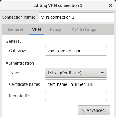
Optional: Configure additional settings by clicking the button. You can configure the following settings:
Identification
-
Domain- If required, enter the domain name.
-
Security
-
Phase1 Algorithmscorresponds to theikeLibreswan parameter. Enter the algorithms to be used to authenticate and set up an encrypted channel. Phase2 Algorithmscorresponds to theespLibreswan parameter. Enter the algorithms to be used for theIPsecnegotiations.Check the
Disable PFSfield to turn off Perfect Forward Secrecy (PFS) to ensure compatibility with old servers that do not support PFS.-
Phase1 Lifetimecorresponds to theikelifetimeLibreswan parameter. This parameter defines how long the key used to encrypt the traffic is valid. -
Phase2 Lifetimecorresponds to thesalifetimeLibreswan parameter. This parameter defines how long a security association is valid.
-
Connectivity
Remote networkcorresponds to therightsubnetLibreswan parameter and defines the destination private remote network that should be reached through the VPN.Check the
narrowingfield to enable narrowing. Note that it is only effective in the IKEv2 negotiation.-
Enable fragmentationcorresponds to thefragmentationLibreswan parameter and defines whether or not to allow IKE fragmentation. Valid values areyes(default) orno. -
Enable Mobikecorresponds to themobikeLibreswan parameter. The parameter defines whether or not to allow Mobility and Multihoming Protocol (MOBIKE) (RFC 4555) to enable a connection to migrate its endpoint without needing to restart the connection from scratch. This is used on mobile devices that switch between wired, wireless or mobile data connections. The values areno(default) oryes.
On the
IPv4 Settingstab, select the IP assignment method and, optionally, set additional static addresses, DNS servers, search domains, and routes.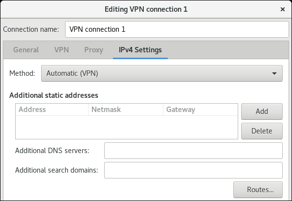
- Save the connection.
-
Close
nm-connection-editor. - If you use this host in a network with DHCP or Stateless Address Autoconfiguration (SLAAC), the connection can be vulnerable to being redirected. For details and mitigation steps, see Assigning a VPN connection to a dedicated routing table to prevent the connection from bypassing the tunnel.
When you add a new connection by clicking the button, NetworkManager creates a new configuration file for that connection and then opens the same dialog that is used for editing an existing connection. The difference between these dialogs is that an existing connection profile has a Details menu entry.
23.3.18. Assigning a VPN connection to a dedicated routing table to prevent the connection from bypassing the tunnel
Both a DHCP server and Stateless Address Autoconfiguration (SLAAC) can add routes to a client’s routing table. For example, a malicious DHCP server can use this feature to force a host with VPN connection to redirect traffic through a physical interface instead of the VPN tunnel. This vulnerability is also known as TunnelVision and described in the CVE-2024-3661 vulnerability article.
To mitigate this vulnerability, you can assign the VPN connection to a dedicated routing table. This prevents the DHCP configuration or SLAAC to manipulate routing decisions for network packets intended for the VPN tunnel.
Follow the steps if at least one of the conditions applies to your environment:
- At least one network interface uses DHCP or SLAAC.
- Your network does not use mechanisms, such as DHCP snooping, that prevent a rogue DHCP server.
Routing the entire traffic through the VPN prevents the host from accessing local network resources.
Prerequisites
- You use NetworkManager 1.40.16-18 or later.
Procedure
- Decide which routing table you want to use. The following steps use table 75. By default, RHEL does not use the tables 1-254, and you can use any of them.
Configure the VPN connection profile to place the VPN routes in a dedicated routing table:
# nmcli connection modify <vpn_connection_profile> ipv4.route-table 75 ipv6.route-table 75Set a low priority value for the table you used in the previous command:
# nmcli connection modify <vpn_connection_profile> ipv4.routing-rules "priority 32345 from all table 75" ipv6.routing-rules "priority 32345 from all table 75"The priority value can be any value between 1 and 32766. The lower the value, the higher the priority.
Reconnect the VPN connection:
# nmcli connection down <vpn_connection_profile> # nmcli connection up <vpn_connection_profile>
Verification
Display the IPv4 routes in table 75:
# ip route show table 75 ... 192.0.2.0/24 via 192.0.2.254 dev vpn_device proto static metric 50 default dev vpn_device proto static scope link metric 50The output confirms that both the route to the remote network and the default gateway are assigned to routing table 75 and, therefore, all traffic is routed through the tunnel. If you set
ipv4.never-default truein the VPN connection profile, a default route is not created and, therefore, not visible in this output.Display the IPv6 routes in table 75:
# ip -6 route show table 75 ... 2001:db8:1::/64 dev vpn_device proto kernel metric 50 pref medium default dev vpn_device proto static metric 50 pref mediumThe output confirms that both the route to the remote network and the default gateway are assigned to routing table 75 and, therefore, all traffic is routed through the tunnel. If you set
ipv4.never-default truein the VPN connection profile, a default route is not created and, therefore, not visible in this output.
23.4. Using MACsec to encrypt layer-2 traffic in the same physical network
You can use MACsec to secure the communication between two devices (point-to-point). For example, your branch office is connected over a Metro-Ethernet connection with the central office, you can configure MACsec on the two hosts that connect the offices to increase the security.
23.4.1. How MACsec increases security
Media Access Control security (MACsec) is a layer-2 protocol that secures different traffic types over the Ethernet links, including:
- Dynamic host configuration protocol (DHCP)
- address resolution protocol (ARP)
- IPv4 and IPv6 traffic
- Any traffic over IP such as TCP or UDP
MACsec encrypts and authenticates all traffic in LANs, by default with the GCM-AES-128 algorithm, and uses a pre-shared key to establish the connection between the participant hosts. To change the pre-shared key, you must update the NM configuration on all network hosts that use MACsec.
A MACsec connection uses an Ethernet device, such as an Ethernet network card, VLAN, or tunnel device, as a parent. You can either set an IP configuration only on the MACsec device to communicate with other hosts only by using the encrypted connection, or you can also set an IP configuration on the parent device. In the latter case, you can use the parent device to communicate with other hosts using an unencrypted connection and the MACsec device for encrypted connections.
MACsec does not require any special hardware. For example, you can use any switch, except if you want to encrypt traffic only between a host and a switch. In this scenario, the switch must also support MACsec.
In other words, you can configure MACsec for two common scenarios:
- Host-to-host
- Host-to-switch and switch-to-other-hosts
You can use MACsec only between hosts being in the same physical or virtual LAN.
Using the MACsec security standard for securing communication at the link layer, also known as layer 2 of the Open Systems Interconnection (OSI) model provides the following notable benefits:
- Encryption at layer 2 eliminates the need for encrypting individual services at layer 7. This reduces the overhead associated with managing a large number of certificates for each endpoint on each host.
- Point-to-point security between directly connected network devices such as routers and switches.
- No changes needed for applications and higher-layer protocols.
23.4.2. Configuring a MACsec connection by using nmcli
You can use the nmcli utility to configure Ethernet interfaces to use MACsec. For example, you can create a MACsec connection between two hosts that are connected over Ethernet.
Procedure
On the first host on which you configure MACsec:
Create the connectivity association key (CAK) and connectivity-association key name (CKN) for the pre-shared key:
Create a 16-byte hexadecimal CAK:
# dd if=/dev/urandom count=16 bs=1 2> /dev/null | hexdump -e '1/2 "%04x"' 50b71a8ef0bd5751ea76de6d6c98c03aCreate a 32-byte hexadecimal CKN:
# dd if=/dev/urandom count=32 bs=1 2> /dev/null | hexdump -e '1/2 "%04x"' f2b4297d39da7330910a74abc0449feb45b5c0b9fc23df1430e1898fcf1c4550
- On both hosts you want to connect over a MACsec connection:
Create the MACsec connection:
# nmcli connection add type macsec con-name macsec0 ifname macsec0 connection.autoconnect yes macsec.parent enp1s0 macsec.mode psk macsec.mka-cak 50b71a8ef0bd5751ea76de6d6c98c03a macsec.mka-ckn f2b4297d39da7330910a74abc0449feb45b5c0b9fc23df1430e1898fcf1c4550Use the CAK and CKN generated in the previous step in the
macsec.mka-cakandmacsec.mka-cknparameters. The values must be the same on every host in the MACsec-protected network.Configure the IP settings on the MACsec connection.
Configure the
IPv4settings. For example, to set a staticIPv4address, network mask, default gateway, and DNS server to themacsec0connection, enter:# nmcli connection modify macsec0 ipv4.method manual ipv4.addresses '192.0.2.1/24' ipv4.gateway '192.0.2.254' ipv4.dns '192.0.2.253'Configure the
IPv6settings. For example, to set a staticIPv6address, network mask, default gateway, and DNS server to themacsec0connection, enter:# nmcli connection modify macsec0 ipv6.method manual ipv6.addresses '2001:db8:1::1/32' ipv6.gateway '2001:db8:1::fffe' ipv6.dns '2001:db8:1::fffd'
Activate the connection:
# nmcli connection up macsec0
Verification
Verify that the traffic is encrypted:
# tcpdump -nn -i enp1s0Optional: Display the unencrypted traffic:
# tcpdump -nn -i macsec0Display MACsec statistics:
# ip macsec showDisplay individual counters for each type of protection: integrity-only (encrypt off) and encryption (encrypt on)
# ip -s macsec show
23.5. Using and configuring firewalld
A firewall is a way to protect machines from any unwanted traffic from outside. It enables users to control incoming network traffic on host machines by defining a set of firewall rules. These rules are used to sort the incoming traffic and either block it or allow it through.
firewalld is a firewall service daemon that provides a dynamic, customizable firewall with a D-Bus interface. Being dynamic, it enables creating, changing, and deleting rules without the necessity of restarting the firewall daemon each time the rules are changed.
You can use firewalld to configure packet filtering required by the majority of typical cases. If firewalld does not cover your scenario, or you want to have complete control of rules, use the nftables framework.
firewalld uses the concepts of zones, policies, and services to simplify traffic management. Zones logically separate a network. Network interfaces and sources can be assigned to a zone. Policies are used to deny or allow traffic flowing between zones. Firewall services are predefined rules that cover all necessary settings to allow incoming traffic for a specific service, and they apply within a zone.
Services use one or more ports or addresses for network communication. Firewalls filter communication based on ports. To allow network traffic for a service, its ports must be open. firewalld blocks all traffic on ports that are not explicitly set as open. Some zones, such as trusted, allow all traffic by default.
firewalld maintains separate runtime and permanent configurations. This allows runtime-only changes. The runtime configuration does not persist after firewalld reload or restart. At startup, it is populated from the permanent configuration.
Note that firewalld with nftables back end does not support passing custom nftables rules to firewalld, using the --direct option.
23.5.1. When to use firewalld, nftables, or iptables
On RHEL 8, you can use the following packet-filtering utilities depending on your scenario:
-
firewalld: Thefirewalldutility simplifies firewall configuration for common use cases. -
nftables: Use thenftablesutility to set up complex and performance-critical firewalls, such as for a whole network. -
iptables: Theiptablesutility on Red Hat Enterprise Linux uses thenf_tableskernel API instead of thelegacyback end. Thenf_tablesAPI provides backward compatibility so that scripts that useiptablescommands still work on Red Hat Enterprise Linux. For new firewall scripts, usenftables.
To prevent the different firewall-related services (firewalld, nftables, or iptables) from influencing each other, run only one of them on a RHEL host, and disable the other services.
23.5.2. Firewall zones
You can use the firewalld utility to separate networks into different zones according to the level of trust that you have with the interfaces and traffic within that network. A connection can only be part of one zone, but you can use that zone for many network connections.
firewalld follows strict principles in regards to zones:
- Traffic ingresses only one zone.
- Traffic egresses only one zone.
- A zone defines a level of trust.
- Intrazone traffic (within the same zone) is allowed by default.
- Interzone traffic (from zone to zone) is denied by default.
Principles 4 and 5 are a consequence of principle 3.
Principle 4 is configurable through the zone option --remove-forward. Principle 5 is configurable by adding new policies.
NetworkManager notifies firewalld of the zone of an interface. You can assign zones to interfaces with the following utilities:
-
NetworkManager -
firewall-configutility -
firewall-cmdutility - The RHEL web console
The RHEL web console, firewall-config, and firewall-cmd can only edit the appropriate NetworkManager configuration files. If you change the zone of the interface using the web console, firewall-cmd, or firewall-config, the request is forwarded to NetworkManager and is not handled by firewalld.
The /usr/lib/firewalld/zones/ directory stores the predefined zones, and you can instantly apply them to any available network interface. These files are copied to the /etc/firewalld/zones/ directory only after they are modified. The default settings of the predefined zones are as follows:
block-
Suitable for: Any incoming network connections are rejected with an icmp-host-prohibited message for
IPv4and icmp6-adm-prohibited forIPv6. - Accepts: Only network connections initiated from within the system.
-
Suitable for: Any incoming network connections are rejected with an icmp-host-prohibited message for
dmz- Suitable for: Computers in your DMZ that are publicly-accessible with limited access to your internal network.
- Accepts: Only selected incoming connections.
dropSuitable for: Any incoming network packets are dropped without any notification.
- Accepts: Only outgoing network connections.
external- Suitable for: External networks with masquerading enabled, especially for routers. Situations when you do not trust the other computers on the network.
- Accepts: Only selected incoming connections.
home- Suitable for: Home environment where you mostly trust the other computers on the network.
- Accepts: Only selected incoming connections.
internal- Suitable for: Internal networks where you mostly trust the other computers on the network.
- Accepts: Only selected incoming connections.
public- Suitable for: Public areas where you do not trust other computers on the network.
- Accepts: Only selected incoming connections.
trusted- Accepts: All network connections.
workSuitable for: Work environment where you mostly trust the other computers on the network.
- Accepts: Only selected incoming connections.
One of these zones is set as the default zone. When interface connections are added to NetworkManager, they are assigned to the default zone. On installation, the default zone in firewalld is the public zone. You can change the default zone.
Make network zone names self-explanatory to help users understand them quickly.
To avoid any security problems, review the default zone configuration and disable any unnecessary services according to your needs and risk assessments.
23.5.3. Firewall policies
The firewall policies specify the desired security state of your network. They outline rules and actions to take for different types of traffic. Typically, the policies contain rules for the following types of traffic:
- Incoming traffic
- Outgoing traffic
- Forward traffic
- Specific services and applications
- Network address translations (NAT)
Firewall policies use the concept of firewall zones. Each zone is associated with a specific set of firewall rules that determine the traffic allowed. Policies apply firewall rules in a stateful, unidirectional manner. This means you only consider one direction of the traffic. The traffic return path is implicitly allowed due to stateful filtering of firewalld.
Policies are associated with an ingress zone and an egress zone. The ingress zone is where the traffic originated (received). The egress zone is where the traffic leaves (sent).
The firewall rules defined in a policy can reference the firewall zones to apply consistent configurations across multiple network interfaces.
23.5.4. Firewall rules
You can use the firewall rules to implement specific configurations for allowing or blocking network traffic. As a result, you can control the flow of network traffic to protect your system from security threats.
Firewall rules typically define certain criteria based on various attributes. The attributes can be as:
- Source IP addresses
- Destination IP addresses
- Transfer Protocols (TCP, UDP, …)
- Ports
- Network interfaces
The firewalld utility organizes the firewall rules into zones (such as public, internal, and others) and policies. Each zone has its own set of rules that determine the level of traffic freedom for network interfaces associated with a particular zone.
23.5.5. Firewall direct rules
The firewalld service provides multiple ways with which to configure rules, including:
- regular rules
- direct rules
One difference between these is how each method interacts with the underlying backend (iptables or nftables).
The direct rules are advanced, low-level rules that allow direct interaction with iptables. They bypass the structured zone-based management of firewalld to give you more control. You manually define the direct rules with the firewall-cmd command by using the raw iptables syntax. For example, firewall-cmd --direct --add-rule ipv4 filter INPUT 0 -s 198.51.100.1 -j DROP. This command adds an iptables rule to drop traffic from the 198.51.100.1 source IP address.
However, using the direct rules also has its drawbacks. Especially when nftables is your primary firewall backend. For example:
-
The direct rules are harder to maintain and can conflict with
nftablesbasedfirewalldconfigurations. -
The direct rules do not support advanced features that you can find in
nftablessuch as raw expressions and stateful objects. -
Direct rules are not future-proof. The
iptablescomponent is deprecated and will eventually be removed from RHEL.
For the previous reasons, you might consider replacing firewalld direct rules with nftables. Review the knowledgebase solution How to replace firewalld direct rules with nftables? to see more details.
23.5.6. Predefined firewalld services
The predefined firewalld services provide a built-in abstraction layer over the low-level firewall rules. It is achieved by mapping commonly used network services, such as SSH or HTTP to their corresponding ports and protocols. Instead of manually specifying these each time, you can refer to a named predefined service. This makes firewall management simpler, less error-prone, and more intuitive.
To see available predefined services:
# firewall-cmd --get-services RH-Satellite-6 RH-Satellite-6-capsule afp amanda-client amanda-k5-client amqp amqps apcupsd audit ausweisapp2 bacula bacula-client bareos-director bareos-filedaemon bareos-storage bb bgp bitcoin bitcoin-rpc bitcoin-testnet bitcoin-testnet-rpc bittorrent-lsd ceph ceph-exporter ceph-mon cfengine checkmk-agent cockpit collectd condor-collector cratedb ctdb dds...To further inspect a particular predefined service:
# sudo firewall-cmd --info-service=RH-Satellite-6 RH-Satellite-6 ports: 5000/tcp 5646-5647/tcp 5671/tcp 8000/tcp 8080/tcp 9090/tcp protocols: source-ports: modules: destination: includes: foreman helpers:The example output shows that the
RH-Satellite-6predefined service listens on ports 5000/tcp 5646-5647/tcp 5671/tcp 8000/tcp 8080/tcp 9090/tcp. Additionally,RH-Satellite-6inherits rules from another predefined service. In this caseforeman.
Each predefined service is stored as an XML file with the same name in the /usr/lib/firewalld/services/ directory.
23.5.7. Working with firewalld zones
Zones represent a concept to manage incoming traffic more transparently. The zones are connected to networking interfaces or assigned a range of source addresses. You manage firewall rules for each zone independently, which enables you to define complex firewall settings and apply them to the traffic.
23.5.7.1. Customizing firewall settings for a specific zone to enhance security
You can strengthen your network security by modifying the firewall settings and associating a specific network interface or connection with a particular firewall zone. By defining granular rules and restrictions for a zone, you can control inbound and outbound traffic based on your intended security levels.
For example, you can achieve the following benefits:
- Protection of sensitive data
- Prevention of unauthorized access
- Mitigation of potential network threats
Prerequisites
-
The
firewalldservice is running.
Procedure
List the available firewall zones:
# firewall-cmd --get-zonesThe
firewall-cmd --get-zonescommand displays all zones that are available on the system, but it does not show any details for particular zones. To see more detailed information for all zones, use thefirewall-cmd --list-all-zonescommand.- Choose the zone you want to use for this configuration.
Modify firewall settings for the chosen zone. For example, to allow the
SSHservice and remove theftpservice:# firewall-cmd --add-service=ssh --zone=<your_chosen_zone> # firewall-cmd --remove-service=ftp --zone=<same_chosen_zone>Assign a network interface to the firewall zone:
List the available network interfaces:
# firewall-cmd --get-active-zonesActivity of a zone is determined by the presence of network interfaces or source address ranges that match its configuration. The default zone is active for unclassified traffic but is not always active if no traffic matches its rules.
Assign a network interface to the chosen zone:
# firewall-cmd --zone=<your_chosen_zone> --change-interface=<interface_name> --permanentAssigning a network interface to a zone is more suitable for applying consistent firewall settings to all traffic on a particular interface (physical or virtual).
The
firewall-cmdcommand, when used with the--permanentoption, often involves updating NetworkManager connection profiles to make changes to the firewall configuration permanent. This integration betweenfirewalldand NetworkManager ensures consistent network and firewall settings.
Verification
Display the updated settings for your chosen zone:
# firewall-cmd --zone=<your_chosen_zone> --list-allThe command output displays all zone settings including the assigned services, network interface, and network connections (sources).
23.5.7.2. Changing the default zone
System administrators assign a zone to a networking interface in its configuration files. If an interface is not assigned to a specific zone, it is assigned to the default zone. After each restart of the firewalld service, firewalld loads the settings for the default zone and makes it active. Note that settings for all other zones are preserved and ready to be used.
Typically, zones are assigned to interfaces by NetworkManager according to the connection.zone setting in NetworkManager connection profiles. Also, after a reboot NetworkManager manages assignments for "activating" those zones.
Prerequisites
-
The
firewalldservice is running.
Procedure
To set up the default zone:
Display the current default zone:
# firewall-cmd --get-default-zoneSet the new default zone:
# firewall-cmd --set-default-zone <zone_name>NoteFollowing this procedure, the setting is a permanent setting, even without the
--permanentoption.
23.5.7.3. Assigning a network interface to a zone
It is possible to define different sets of rules for different zones and then change the settings quickly by changing the zone for the interface that is being used. With multiple interfaces, a specific zone can be set for each of them to distinguish traffic that is coming through them.
Procedure
To assign the zone to a specific interface:
List the active zones and the interfaces assigned to them:
# firewall-cmd --get-active-zonesAssign the interface to a different zone:
# firewall-cmd --zone=zone_name --change-interface=interface_name --permanent
23.5.7.4. Adding a source
To route incoming traffic into a specific zone, add the source to that zone. The source can be an IP address or an IP mask in the classless inter-domain routing (CIDR) notation.
In case you add multiple zones with an overlapping network range, they are ordered alphanumerically by zone name and only the first one is considered.
To set the source in the current zone:
# firewall-cmd --add-source=<source>To set the source IP address for a specific zone:
# firewall-cmd --zone=zone-name --add-source=<source>
The following procedure allows all incoming traffic from 192.168.2.15 in the trusted zone:
Procedure
List all available zones:
# firewall-cmd --get-zonesAdd the source IP to the trusted zone in the permanent mode:
# firewall-cmd --zone=trusted --add-source=192.168.2.15Make the new settings persistent:
# firewall-cmd --runtime-to-permanent
23.5.7.5. Removing a source
When you remove a source from a zone, the traffic which originates from the source is no longer directed through the rules specified for that source. Instead, the traffic falls back to the rules and settings of the zone associated with the interface from which it originates, or goes to the default zone.
Procedure
List allowed sources for the required zone:
# firewall-cmd --zone=zone-name --list-sourcesRemove the source from the zone permanently:
# firewall-cmd --zone=zone-name --remove-source=<source>Make the new settings persistent:
# firewall-cmd --runtime-to-permanent
23.5.7.6. Assigning a zone to a connection using nmcli
You can add a firewalld zone to a NetworkManager connection using the nmcli utility.
Procedure
Assign the zone to the
NetworkManagerconnection profile:# nmcli connection modify profile connection.zone zone_nameActivate the connection:
# nmcli connection up profile
23.5.7.7. Manually assigning a zone to a network connection in an ifcfg file
When the connection is managed by NetworkManager, it must be aware of a zone that it uses. For every network connection profile, a zone can be specified, which provides the flexibility of various firewall settings according to the location of the computer with portable devices. Thus, zones and settings can be specified for different locations, such as company or home.
Procedure
To set a zone for a connection, edit the
/etc/sysconfig/network-scripts/ifcfg-connection_namefile and add a line that assigns a zone to this connection:ZONE=zone_name
23.5.7.8. Creating a new zone
To use custom zones, create a new zone and use it just like a predefined zone. New zones require the --permanent option, otherwise the command does not work.
Prerequisites
-
The
firewalldservice is running.
Procedure
Create a new zone:
# firewall-cmd --permanent --new-zone=zone-nameMake the new zone usable:
# firewall-cmd --reloadThe command applies recent changes to the firewall configuration without interrupting network services that are already running.
Verification
Check if the new zone is added to your permanent settings:
# firewall-cmd --get-zones --permanent
23.5.7.9. Enabling zones by using the web console
You can apply predefined and existing firewall zones on a particular interface or a range of IP addresses through the RHEL web console.
Prerequisites
- You have installed the RHEL 8 web console.
- You have enabled the cockpit service.
Your user account is allowed to log in to the web console.
For instructions, see Installing and enabling the web console.
Procedure
Log in to the RHEL 8 web console.
For details, see Logging in to the web console.
- Click Networking.
Click on the button.
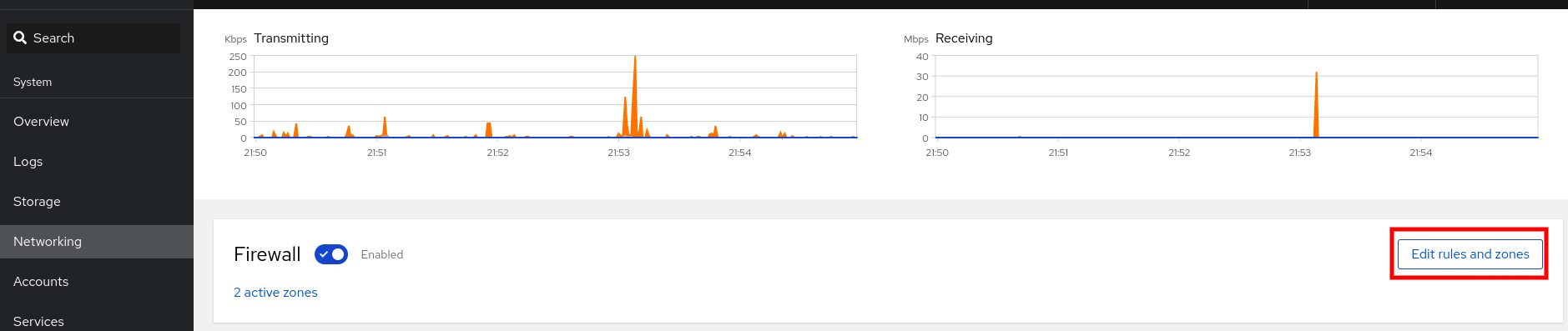
If you do not see the button, log in to the web console with the administrator privileges.
- In the Firewall section, click Add new zone.
In the Add zone dialog box, select a zone from the Trust level options.
The web console displays all zones predefined in the
firewalldservice.- In the Interfaces part, select an interface or interfaces on which the selected zone is applied.
In the Allowed Addresses part, you can select whether the zone is applied on:
- the whole subnet
or a range of IP addresses in the following format:
- 192.168.1.0
- 192.168.1.0/24
- 192.168.1.0/24, 192.168.1.0
Click on the button.
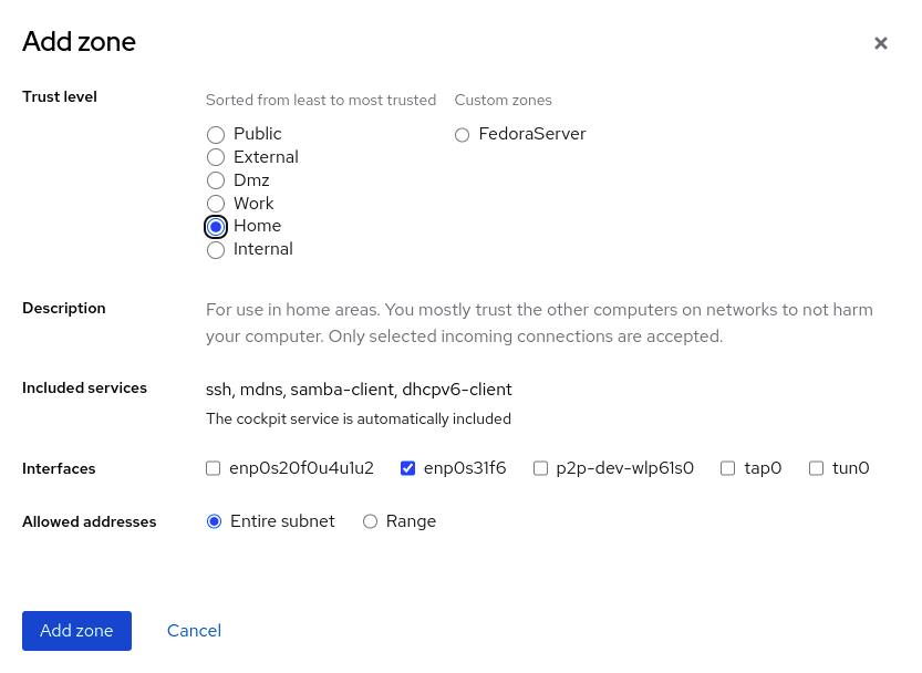
Verification
Check the configuration in the Firewall section:
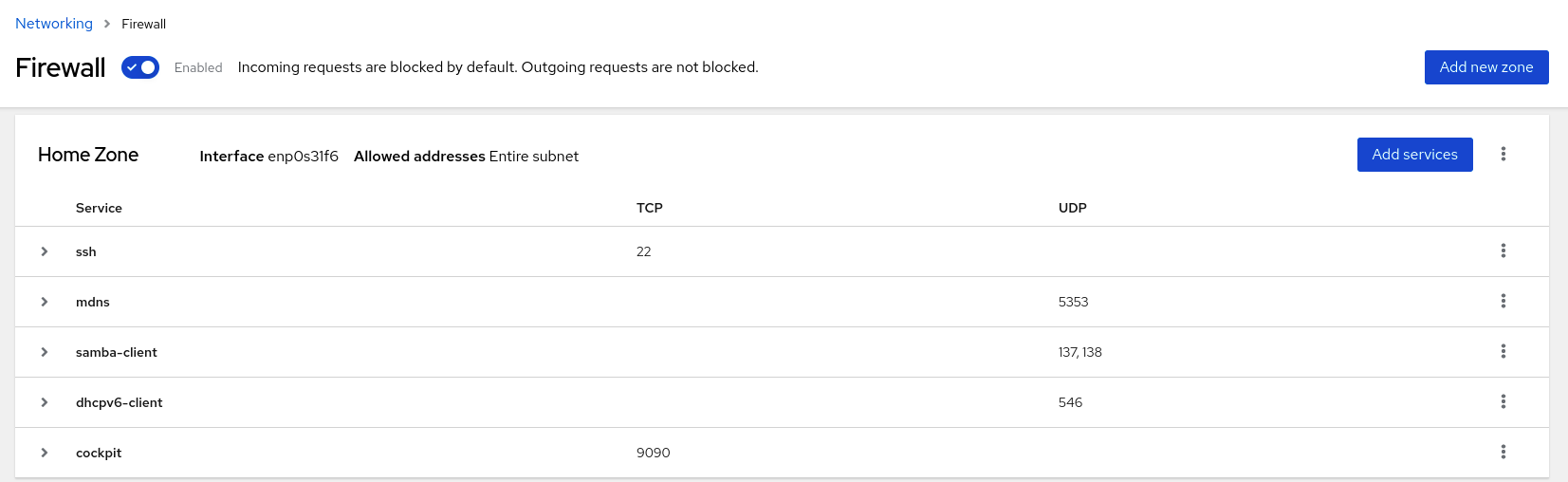
23.5.7.10. Disabling zones by using the web console
You can disable a firewall zone in your firewall configuration by using the web console.
Prerequisites
- You have installed the RHEL 8 web console.
- You have enabled the cockpit service.
Your user account is allowed to log in to the web console.
For instructions, see Installing and enabling the web console.
Procedure
Log in to the RHEL 8 web console.
For details, see Logging in to the web console.
- Click Networking.
Click on the button.
If you do not see the button, log in to the web console with the administrator privileges.
Click on the Options icon at the zone you want to remove.
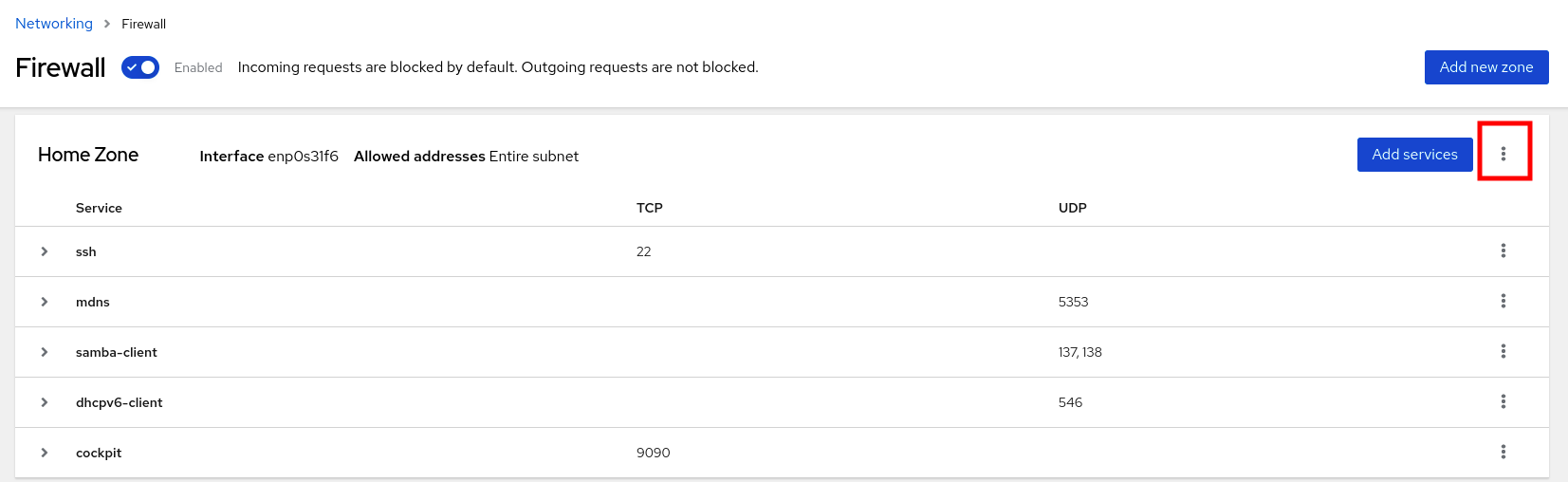
- Click Delete.
The zone is now disabled and the interface does not include opened services and ports which were configured in the zone.
23.5.7.11. Using zone targets to set default behavior for incoming traffic
For every zone, you can set a default behavior that handles incoming traffic that is not further specified. Such behavior is defined by setting the target of the zone. There are four options:
-
ACCEPT: Accepts all incoming packets except those disallowed by specific rules. -
REJECT: Rejects all incoming packets except those allowed by specific rules. Whenfirewalldrejects packets, the source machine is informed about the rejection. -
DROP: Drops all incoming packets except those allowed by specific rules. Whenfirewallddrops packets, the source machine is not informed about the packet drop. -
default: Similar behavior as forREJECT, but with special meanings in certain scenarios.
Prerequisites
-
The
firewalldservice is running.
Procedure
To set a target for a zone:
List the information for the specific zone to see the default target:
# firewall-cmd --zone=zone-name --list-allSet a new target in the zone:
# firewall-cmd --permanent --zone=zone-name --set-target=<default|ACCEPT|REJECT|DROP>
23.5.7.12. Configuring dynamic updates for allowlisting with IP sets
You can make near real-time updates to flexibly allow specific IP addresses or ranges in the IP sets even in unpredictable conditions. These updates can be triggered by various events, such as detection of security threats or changes in the network behavior. Typically, such a solution leverages automation to reduce manual effort and improve security by responding quickly to the situation.
Prerequisites
-
The
firewalldservice is running.
Procedure
Create an IP set with a meaningful name:
# firewall-cmd --permanent --new-ipset=allowlist --type=hash:ipThe new IP set called
allowlistcontains IP addresses that you want your firewall to allow.Add a dynamic update to the IP set:
# firewall-cmd --permanent --ipset=allowlist --add-entry=198.51.100.10This configuration updates the
allowlistIP set with a newly added IP address that is allowed to pass network traffic by your firewall.Create a firewall rule that references the previously created IP set:
# firewall-cmd --permanent --zone=public --add-source=ipset:allowlistWithout this rule, the IP set would not have any impact on network traffic. The default firewall policy would prevail.
Reload the firewall configuration to apply the changes:
# firewall-cmd --reload
Verification
List all IP sets:
# firewall-cmd --get-ipsets allowlistList the active rules:
# firewall-cmd --list-all public (active) target: default icmp-block-inversion: no interfaces: enp0s1 sources: ipset:allowlist services: cockpit dhcpv6-client ssh ports: protocols: ...The
sourcessection of the command-line output provides insights to what origins of traffic (hostnames, interfaces, IP sets, subnets, and others) are permitted or denied access to a particular firewall zone. In this case, the IP addresses contained in theallowlistIP set are allowed to pass traffic through the firewall for thepubliczone.Explore the contents of your IP set:
# cat /etc/firewalld/ipsets/allowlist.xml <?xml version="1.0" encoding="utf-8"?> <ipset type="hash:ip"> <entry>198.51.100.10</entry> </ipset>
Next steps
-
Use a script or a security utility to fetch your threat intelligence feeds and update
allowlistaccordingly in an automated fashion.
23.5.8. Controlling network traffic using firewalld
The firewalld package installs a large number of predefined service files and you can add more or customize them. You can then use these service definitions to open or close ports for services without knowing the protocol and port numbers they use.
23.5.8.1. Controlling traffic with predefined services using the CLI
The most straightforward method to control traffic is to add a predefined service to firewalld. This opens all necessary ports and modifies other settings according to the service definition file.
Prerequisites
-
The
firewalldservice is running.
Procedure
Check that the service in
firewalldis not already allowed:# firewall-cmd --list-services ssh dhcpv6-clientThe command lists the services that are enabled in the default zone.
List all predefined services in
firewalld:# firewall-cmd --get-services RH-Satellite-6 amanda-client amanda-k5-client bacula bacula-client bitcoin bitcoin-rpc bitcoin-testnet bitcoin-testnet-rpc ceph ceph-mon cfengine condor-collector ctdb dhcp dhcpv6 dhcpv6-client dns docker-registry ...The command displays a list of available services for the default zone.
Add the service to the list of services that
firewalldallows:# firewall-cmd --add-service=<service_name>The command adds the specified service to the default zone.
Make the new settings persistent:
# firewall-cmd --runtime-to-permanentThe command applies these runtime changes to the permanent configuration of the firewall. By default, it applies these changes to the configuration of the default zone.
Verification
List all permanent firewall rules:
# firewall-cmd --list-all --permanent public target: default icmp-block-inversion: no interfaces: sources: services: cockpit dhcpv6-client ssh ports: protocols: forward: no masquerade: no forward-ports: source-ports: icmp-blocks: rich rules:The command displays complete configuration with the permanent firewall rules of the default firewall zone (
public).Check the validity of the permanent configuration of the
firewalldservice.# firewall-cmd --check-config successIf the permanent configuration is invalid, the command returns an error with further details:
# firewall-cmd --check-config Error: INVALID_PROTOCOL: 'public.xml': 'tcpx' not from {'tcp'|'udp'|'sctp'|'dccp'}You can also manually inspect the permanent configuration files to verify the settings. The main configuration file is
/etc/firewalld/firewalld.conf. The zone-specific configuration files are in the/etc/firewalld/zones/directory and the policies are in the/etc/firewalld/policies/directory.
23.5.8.2. Enabling services on the firewall by using the web console
By default, services are added to the default firewall zone. If you use more firewall zones on more network interfaces, you must select a zone first and then add the service with port.
The RHEL 8 web console displays predefined firewalld services and you can add them to active firewall zones.
The RHEL 8 web console configures the firewalld service.
The web console does not allow generic firewalld rules which are not listed in the web console.
Prerequisites
- You have installed the RHEL 8 web console.
- You have enabled the cockpit service.
Your user account is allowed to log in to the web console.
For instructions, see Installing and enabling the web console.
Procedure
Log in to the RHEL 8 web console.
For details, see Logging in to the web console.
- Click Networking.
Click on the button.
If you do not see the button, log in to the web console with the administrator privileges.
In the Firewall section, select a zone for which you want to add the service and click Add Services.
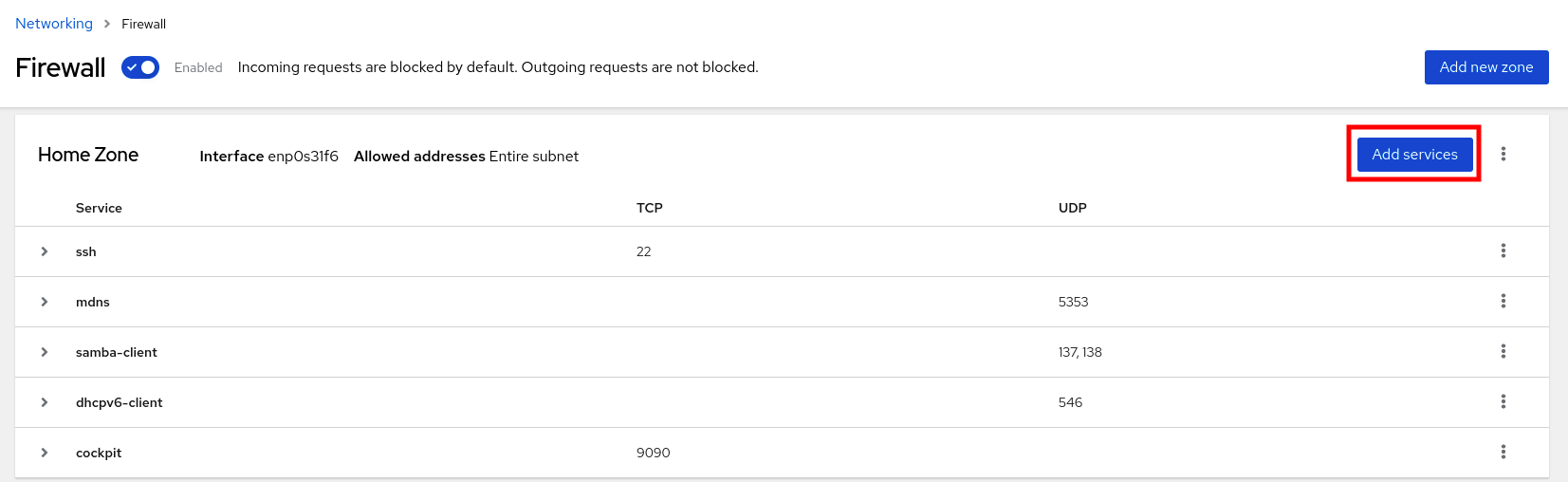
- In the Add Services dialog box, find the service you want to enable on the firewall.
Enable services according to your scenario:
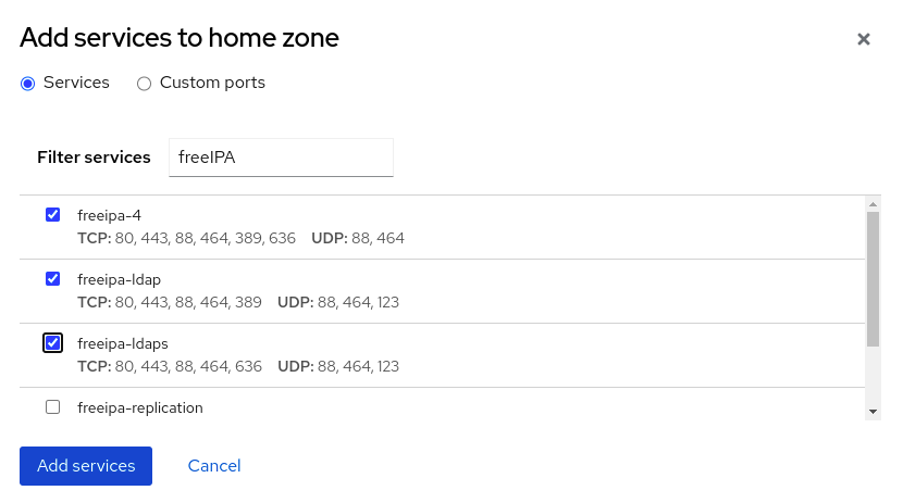
- Click Add Services.
At this point, the RHEL 8 web console displays the service in the zone’s list of Services.
23.5.8.3. Configuring custom ports by using the web console
You can add configure custom ports for services through the RHEL web console.
Prerequisites
- You have installed the RHEL 8 web console.
- You have enabled the cockpit service.
Your user account is allowed to log in to the web console.
For instructions, see Installing and enabling the web console.
-
The
firewalldservice is running.
Procedure
Log in to the RHEL 8 web console.
For details, see Logging in to the web console.
- Click Networking.
Click on the button.
If you do not see the button, log in to the web console with the administrative privileges.
In the Firewall section, select a zone for which you want to configure a custom port and click Add Services.
- In the Add services dialog box, click on the radio button.
In the TCP and UDP fields, add ports according to examples. You can add ports in the following formats:
- Port numbers such as 22
- Range of port numbers such as 5900-5910
- Aliases such as nfs, rsync
NoteYou can add multiple values into each field. Values must be separated with the comma and without the space, for example: 8080,8081,http
After adding the port number in the TCP filed, the UDP filed, or both, verify the service name in the Name field.
The Name field displays the name of the service for which is this port reserved. You can rewrite the name if you are sure that this port is free to use and no server needs to communicate on this port.
- In the Name field, add a name for the service including defined ports.
Click on the button.
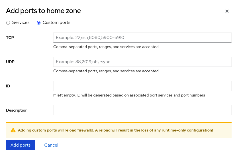
To verify the settings, go to the Firewall page and find the service in the list of zone’s Services.
23.5.9. Filtering forwarded traffic between zones
firewalld enables you to control the flow of network data between different firewalld zones. By defining rules and policies, you can manage how traffic is allowed or blocked when it moves between these zones.
The policy objects feature provides forward and output filtering in firewalld. You can use firewalld to filter traffic between different zones to allow access to locally hosted VMs to connect the host.
23.5.9.1. The relationship between policy objects and zones
Policy objects allow the user to attach firewalld’s primitives such as services, ports, and rich rules to the policy. You can apply the policy objects to traffic that passes between zones in a stateful and unidirectional manner.
# firewall-cmd --permanent --new-policy myOutputPolicy
# firewall-cmd --permanent --policy myOutputPolicy --add-ingress-zone HOST
# firewall-cmd --permanent --policy myOutputPolicy --add-egress-zone ANY
HOST and ANY are the symbolic zones used in the ingress and egress zone lists.
-
The
HOSTsymbolic zone allows policies for the traffic originating from or has a destination to the host running firewalld. -
The
ANYsymbolic zone applies policy to all the current and future zones.ANYsymbolic zone acts as a wildcard for all zones.
23.5.9.2. Using priorities to sort policies
Multiple policies can apply to the same set of traffic, therefore, priorities should be used to create an order of precedence for the policies that may be applied.
To set a priority to sort the policies:
# firewall-cmd --permanent --policy mypolicy --set-priority -500In the above example -500 is a lower priority value but has higher precedence. Thus, -500 will execute before -100.
Lower numerical priority values have higher precedence and are applied first.
23.5.9.3. Using policy objects to filter traffic between locally hosted containers and a network physically connected to the host
The policy objects feature allows users to filter traffic between Podman and firewalld zones.
Red Hat recommends blocking all traffic by default and opening the selective services needed for the Podman utility.
Procedure
Create a new firewall policy:
# firewall-cmd --permanent --new-policy podmanToAnyBlock all traffic from Podman to other zones and allow only necessary services on Podman:
# firewall-cmd --permanent --policy podmanToAny --set-target REJECT # firewall-cmd --permanent --policy podmanToAny --add-service dhcp # firewall-cmd --permanent --policy podmanToAny --add-service dns # firewall-cmd --permanent --policy podmanToAny --add-service httpsCreate a new Podman zone:
# firewall-cmd --permanent --new-zone=podmanDefine the ingress zone for the policy:
# firewall-cmd --permanent --policy podmanToHost --add-ingress-zone podmanDefine the egress zone for all other zones:
# firewall-cmd --permanent --policy podmanToHost --add-egress-zone ANYSetting the egress zone to ANY means that you filter from Podman to other zones. If you want to filter to the host, then set the egress zone to HOST.
Restart the firewalld service:
# systemctl restart firewalld
Verification
Verify the Podman firewall policy to other zones:
# firewall-cmd --info-policy podmanToAny podmanToAny (active) ... target: REJECT ingress-zones: podman egress-zones: ANY services: dhcp dns https ...
23.5.9.4. Setting the default target of policy objects
You can specify --set-target options for policies. The following targets are available:
-
ACCEPT- accepts the packet -
DROP- drops the unwanted packets -
REJECT- rejects unwanted packets with an ICMP reply CONTINUE(default) - packets will be subject to rules in following policies and zones.# firewall-cmd --permanent --policy mypolicy --set-target CONTINUE
Verification
Verify information about the policy
# firewall-cmd --info-policy mypolicy
23.5.10. Configuring NAT using firewalld
With firewalld, you can configure the following network address translation (NAT) types:
- Masquerading
- Destination NAT (DNAT)
- Redirect
23.5.10.1. Network address translation types
These are the different network address translation (NAT) types:
- Masquerading
Use one of these NAT types to change the source IP address of packets. For example, Internet Service Providers (ISPs) do not route private IP ranges, such as
10.0.0.0/8. If you use private IP ranges in your network and users should be able to reach servers on the internet, map the source IP address of packets from these ranges to a public IP address.Masquerading automatically uses the IP address of the outgoing interface. Therefore, use masquerading if the outgoing interface uses a dynamic IP address.
- Destination NAT (DNAT)
- Use this NAT type to rewrite the destination address and port of incoming packets. For example, if your web server uses an IP address from a private IP range and is, therefore, not directly accessible from the internet, you can set a DNAT rule on the router to redirect incoming traffic to this server.
- Redirect
- This type is a special case of DNAT that redirects packets to a different port on the local machine. For example, if a service runs on a different port than its standard port, you can redirect incoming traffic from the standard port to this specific port.
23.5.10.2. Configuring IP address masquerading
You can enable IP masquerading on your system. IP masquerading hides individual machines behind a gateway when accessing the internet.
Procedure
To check if IP masquerading is enabled (for example, for the
externalzone), enter the following command asroot:# firewall-cmd --zone=external --query-masqueradeThe command prints
yeswith exit status0if enabled. It printsnowith exit status1otherwise. Ifzoneis omitted, the default zone will be used.To enable IP masquerading, enter the following command as
root:# firewall-cmd --zone=external --add-masquerade-
To make this setting persistent, pass the
--permanentoption to the command. To disable IP masquerading, enter the following command as
root:# firewall-cmd --zone=external --remove-masqueradeTo make this setting permanent, pass the
--permanentoption to the command.
23.5.10.3. Using DNAT to forward incoming HTTP traffic
You can use destination network address translation (DNAT) to direct incoming traffic from one destination address and port to another. Typically, this is useful for redirecting incoming requests from an external network interface to specific internal servers or services.
Prerequisites
-
The
firewalldservice is running.
Procedure
Forward incoming HTTP traffic:
# firewall-cmd --zone=public --add-forward-port=port=80:proto=tcp:toaddr=198.51.100.10:toport=8080 --permanentThe previous command defines a DNAT rule with the following settings:
-
--zone=public- The firewall zone for which you configure the DNAT rule. You can adjust this to whatever zone you need. -
--add-forward-port- The option that indicates you are adding a port-forwarding rule. -
port=80- The external destination port. -
proto=tcp- The protocol indicating that you forward TCP traffic. -
toaddr=198.51.100.10- The destination IP address. -
toport=8080- The destination port of the internal server. -
--permanent- The option that makes the DNAT rule persistent across reboots.
-
Reload the firewall configuration to apply the changes:
# firewall-cmd --reload
Verification
Verify the DNAT rule for the firewall zone that you used:
# firewall-cmd --list-forward-ports --zone=public port=80:proto=tcp:toport=8080:toaddr=198.51.100.10Alternatively, view the corresponding XML configuration file:
# cat /etc/firewalld/zones/public.xml <?xml version="1.0" encoding="utf-8"?> <zone> <short>Public</short> <description>For use in public areas. You do not trust the other computers on networks to not harm your computer. Only selected incoming connections are accepted.</description> <service name="ssh"/> <service name="dhcpv6-client"/> <service name="cockpit"/> <forward-port port="80" protocol="tcp" to-port="8080" to-addr="198.51.100.10"/> <forward/> </zone>
23.5.10.4. Redirecting traffic from a non-standard port to make the web service accessible on a standard port
You can use the redirect mechanism to make the web service that internally runs on a non-standard port accessible without requiring users to specify the port in the URL. As a result, the URLs are simpler and provide better browsing experience, while a non-standard port is still used internally or for specific requirements.
Prerequisites
-
The
firewalldservice is running.
Procedure
Create the NAT redirect rule:
# firewall-cmd --zone=public --add-forward-port=port=<standard_port>:proto=tcp:toport=<non_standard_port> --permanentThe previous command defines the NAT redirect rule with the following settings:
-
--zone=public- The firewall zone, for which you configure the rule. You can adjust this to whatever zone you need. -
--add-forward-port=port=<non_standard_port>- The option that indicates you are adding a port-forwarding (redirecting) rule with source port on which you initially receive the incoming traffic. -
proto=tcp- The protocol indicating that you redirect TCP traffic. -
toport=<standard_port>- The destination port, to which the incoming traffic should be redirected after being received on the source port. -
--permanent- The option that makes the rule persist across reboots.
-
Reload the firewall configuration to apply the changes:
# firewall-cmd --reload
Verification
Verify the redirect rule for the firewall zone that you used:
# firewall-cmd --list-forward-ports port=8080:proto=tcp:toport=80:toaddr=Alternatively, view the corresponding XML configuration file:
# cat /etc/firewalld/zones/public.xml <?xml version="1.0" encoding="utf-8"?> <zone> <short>Public</short> <description>For use in public areas. You do not trust the other computers on networks to not harm your computer. Only selected incoming connections are accepted.</description> <service name="ssh"/> <service name="dhcpv6-client"/> <service name="cockpit"/> <forward-port port="8080" protocol="tcp" to-port="80"/> <forward/> </zone>
23.5.11. Prioritizing rich rules
Rich rules provide a more advanced and flexible way to define firewall rules. Rich rules are particularly useful where services, ports, and so on are not enough to express complex firewall rules.
Concepts behind rich rules:
- granularity and flexibility
- You can define detailed conditions for network traffic based on more specific criteria.
- rule structure
A rich rule consists of a family (IPv4 or IPv6), followed by conditions and actions.
rule family="ipv4|ipv6" [conditions] [actions]- conditions
- They allow rich rules to apply only when certain criteria are met.
- actions
- You can define what happens to network traffic that matches the conditions.
- combining multiple conditions
- You can create more specific and complex filtering.
- hierarchical control and reusability
- You can combine rich rules with other firewall mechanisms such as zones or services.
By default, rich rules are organized based on their rule action. For example, deny rules have precedence over allow rules. The priority parameter in rich rules provides administrators fine-grained control over rich rules and their execution order. When using the priority parameter, rules are sorted first by their priority values in ascending order. When more rules have the same priority, their order is determined by the rule action, and if the action is also the same, the order may be undefined.
23.5.11.1. How the priority parameter organizes rules into different chains
You can set the priority parameter in a rich rule to any number between -32768 and 32767, and lower numerical values have higher precedence.
The firewalld service organizes rules based on their priority value into different chains:
-
Priority lower than 0: the rule is redirected into a chain with the
_presuffix. -
Priority higher than 0: the rule is redirected into a chain with the
_postsuffix. -
Priority equals 0: based on the action, the rule is redirected into a chain with the
_log,_deny, or_allowthe action.
Inside these sub-chains, firewalld sorts the rules based on their priority value.
23.5.11.2. Setting the priority of a rich rule
The following is an example of how to create a rich rule that uses the priority parameter to log all traffic that is not allowed or denied by other rules. You can use this rule to flag unexpected traffic.
Procedure
Add a rich rule with a very low precedence to log all traffic that has not been matched by other rules:
# firewall-cmd --add-rich-rule='rule priority=32767 log prefix="UNEXPECTED: " limit value="5/m"'The command additionally limits the number of log entries to
5per minute.
Verification
Display the
nftablesrule that the command in the previous step created:# nft list chain inet firewalld filter_IN_public_post table inet firewalld { chain filter_IN_public_post { log prefix "UNEXPECTED: " limit rate 5/minute } }
23.5.12. Enabling traffic forwarding between different interfaces or sources within a firewalld zone
Intra-zone forwarding is a firewalld feature that enables traffic forwarding between interfaces or sources within a firewalld zone.
23.5.12.1. The difference between intra-zone forwarding and zones with the default target set to ACCEPT
With intra-zone forwarding enabled, the traffic within a single firewalld zone can flow from one interface or source to another interface or source. The zone specifies the trust level of interfaces and sources. If the trust level is the same, the traffic stays inside the same zone.
Enabling intra-zone forwarding in the default zone of firewalld, applies only to the interfaces and sources added to the current default zone.
firewalld uses different zones to manage incoming and outgoing traffic. Each zone has its own set of rules and behaviors. For example, the trusted zone, allows all forwarded traffic by default.
Other zones can have different default behaviors. In standard zones, forwarded traffic is typically dropped by default when the target of the zone is set to default.
To control how the traffic is forwarded between different interfaces or sources within a zone, make sure you understand and configure the target of the zone accordingly.
23.5.12.2. Using intra-zone forwarding to forward traffic between an Ethernet and Wi-Fi network
You can use intra-zone forwarding to forward traffic between interfaces and sources within the same firewalld zone. This feature brings the following benefits:
-
Seamless connectivity between wired and wireless devices (you can forward traffic between an Ethernet network connected to
enp1s0and a Wi-Fi network connected towlp0s20) - Support for flexible work environments
- Shared resources that are accessible and used by multiple devices or users within a network (such as printers, databases, network-attached storage, and others)
- Efficient internal networking (such as smooth communication, reduced latency, resource accessibility, and others)
You can enable this functionality for individual firewalld zones.
Procedure
Enable packet forwarding in the kernel:
# echo "net.ipv4.ip_forward=1" > /etc/sysctl.d/95-IPv4-forwarding.conf # sysctl -p /etc/sysctl.d/95-IPv4-forwarding.confEnsure that interfaces between which you want to enable intra-zone forwarding are assigned only to the
internalzone:# firewall-cmd --get-active-zonesIf the interface is currently assigned to a zone other than
internal, reassign it:# firewall-cmd --zone=internal --change-interface=interface_name --permanentAdd the
enp1s0andwlp0s20interfaces to theinternalzone:# firewall-cmd --zone=internal --add-interface=enp1s0 --add-interface=wlp0s20Enable intra-zone forwarding:
# firewall-cmd --zone=internal --add-forward
Verification
The following Verification require that the nmap-ncat package is installed on both hosts.
-
Log in to a host that is on the same network as the
enp1s0interface of the host on which you enabled zone forwarding. Start an echo service with
ncatto test connectivity:# ncat -e /usr/bin/cat -l 12345-
Log in to a host that is in the same network as the
wlp0s20interface. Connect to the echo server running on the host that is in the same network as the
enp1s0:# ncat <other_host> 12345- Type something and press . Verify the text is sent back.
23.5.13. Configuring firewalld by using RHEL system roles
RHEL system roles is a set of contents for the Ansible automation utility. This content together with the Ansible automation utility provides a consistent configuration interface to remotely manage multiple systems at once.
The rhel-system-roles package contains the rhel-system-roles.firewall RHEL system role. This role was introduced for automated configurations of the firewalld service.
With the firewall RHEL system role you can configure many different firewalld parameters, for example:
- Zones
- The services for which packets should be allowed
- Granting, rejection, or dropping of traffic access to ports
- Forwarding of ports or port ranges for a zone
23.5.13.1. Resetting the firewalld settings by using the firewall RHEL system role
Over time, updates to your firewall configuration can accumulate to the point, where they could lead to unintended security risks. With the firewall RHEL system role, you can reset the firewalld settings to their default state in an automated fashion. This way you can efficiently remove any unintentional or insecure firewall rules and simplify their management.
Prerequisites
- You have prepared the control node and the managed nodes
- You are logged in to the control node as a user who can run playbooks on the managed nodes.
-
The account you use to connect to the managed nodes has
sudopermissions on them.
Procedure
Create a playbook file, for example
~/playbook.yml, with the following content:--- - name: Reset firewalld example hosts: managed-node-01.example.com tasks: - name: Reset firewalld ansible.builtin.include_role: name: redhat.rhel_system_roles.firewall vars: firewall: - previous: replacedThe settings specified in the example playbook include the following:
previous: replacedRemoves all existing user-defined settings and resets the
firewalldsettings to defaults. If you combine theprevious:replacedparameter with other settings, thefirewallrole removes all existing settings before applying new ones.For details about all variables used in the playbook, see the
/usr/share/ansible/roles/rhel-system-roles.firewall/README.mdfile on the control node.
Validate the playbook syntax:
$ ansible-playbook --syntax-check ~/playbook.ymlNote that this command only validates the syntax and does not protect against a wrong but valid configuration.
Run the playbook:
$ ansible-playbook ~/playbook.yml
Verification
Run this command on the control node to remotely check that all firewall configuration on your managed node was reset to its default values:
# ansible managed-node-01.example.com -m ansible.builtin.command -a 'firewall-cmd --list-all-zones'
23.5.13.2. Forwarding incoming traffic in firewalld from one local port to a different local port by using the firewall RHEL system role
You can use the firewall RHEL system role to remotely configure forwarding of incoming traffic from one local port to a different local port.
For example, if you have an environment where multiple services co-exist on the same machine and need the same default port, there are likely to become port conflicts. These conflicts can disrupt services and cause a downtime. With the firewall RHEL system role, you can efficiently forward traffic to alternative ports to ensure that your services can run simultaneously without modification to their configuration.
Prerequisites
- You have prepared the control node and the managed nodes
- You are logged in to the control node as a user who can run playbooks on the managed nodes.
-
The account you use to connect to the managed nodes has
sudopermissions on them.
Procedure
Create a playbook file, for example
~/playbook.yml, with the following content:--- - name: Configure firewalld hosts: managed-node-01.example.com tasks: - name: Forward incoming traffic on port 8080 to 443 ansible.builtin.include_role: name: redhat.rhel_system_roles.firewall vars: firewall: - forward_port: 8080/tcp;443; state: enabled runtime: true permanent: trueThe settings specified in the example playbook include the following:
forward_port: 8080/tcp;443- Traffic coming to the local port 8080 using the TCP protocol is forwarded to the port 443.
runtime: trueEnables changes in the runtime configuration. The default is set to
true.For details about all variables used in the playbook, see the
/usr/share/ansible/roles/rhel-system-roles.firewall/README.mdfile on the control node.
Validate the playbook syntax:
$ ansible-playbook --syntax-check ~/playbook.ymlNote that this command only validates the syntax and does not protect against a wrong but valid configuration.
Run the playbook:
$ ansible-playbook ~/playbook.yml
Verification
On the control node, run the following command to remotely check the forwarded-ports on your managed node:
# ansible managed-node-01.example.com -m ansible.builtin.command -a 'firewall-cmd --list-forward-ports' managed-node-01.example.com | CHANGED | rc=0 >> port=8080:proto=tcp:toport=443:toaddr=
23.5.13.3. Configuring a firewalld DMZ zone by using the firewall RHEL system role
As a system administrator, you can use the firewall RHEL system role to configure a dmz zone on the enp1s0 interface to permit HTTPS traffic to the zone. In this way, you enable external users to access your web servers.
Prerequisites
- You have prepared the control node and the managed nodes
- You are logged in to the control node as a user who can run playbooks on the managed nodes.
-
The account you use to connect to the managed nodes has
sudopermissions on them.
Procedure
Create a playbook file, for example
~/playbook.yml, with the following content:--- - name: Configure firewalld hosts: managed-node-01.example.com tasks: - name: Creating a DMZ with access to HTTPS port and masquerading for hosts in DMZ ansible.builtin.include_role: name: redhat.rhel_system_roles.firewall vars: firewall: - zone: dmz interface: enp1s0 service: https state: enabled runtime: true permanent: trueFor details about all variables used in the playbook, see the
/usr/share/ansible/roles/rhel-system-roles.firewall/README.mdfile on the control node.Validate the playbook syntax:
$ ansible-playbook --syntax-check ~/playbook.ymlNote that this command only validates the syntax and does not protect against a wrong but valid configuration.
Run the playbook:
$ ansible-playbook ~/playbook.yml
Verification
On the control node, run the following command to remotely check the information about the
dmzzone on your managed node:# ansible managed-node-01.example.com -m ansible.builtin.command -a 'firewall-cmd --zone=dmz --list-all' managed-node-01.example.com | CHANGED | rc=0 >> dmz (active) target: default icmp-block-inversion: no interfaces: enp1s0 sources: services: https ssh ports: protocols: forward: no masquerade: no forward-ports: source-ports: icmp-blocks:
23.6. Getting started with nftables
If your scenario does not fall under typical packet-filtering cases covered by firewalld, or you want to have complete control of rules, you can use the nftables framework.
The nftables framework classifies packets, and it is the successor to the iptables, ip6tables, arptables, ebtables, and ipset utilities. It offers numerous improvements in convenience, features, and performance over previous packet-filtering tools, most notably:
- Built-in lookup tables instead of linear processing
-
A single framework for both the
IPv4andIPv6protocols - Updating the kernel rule set in place through transactions instead of fetching, updating, and storing the entire rule set
-
Support for debugging and tracing in the rule set (
nftrace) and monitoring trace events (in thenfttool) - More consistent and compact syntax, no protocol-specific extensions
- A Netlink API for third-party applications
The nftables framework uses tables to store chains. The chains contain individual rules for performing actions. The nft utility replaces all tools from the previous packet-filtering frameworks. You can use the libnftables library for low-level interaction with nftables Netlink API through the libnftnl library.
To display the effect of rule set changes, use the nft list ruleset command. To clear the kernel rule set, use the nft flush ruleset command. Note that this may also affect the rule set installed by the iptables-nft command, as it utilizes the same kernel infrastructure.
23.6.1. Creating and managing nftables tables, chains, and rules
You can display nftables rule sets and manage them.
23.6.1.1. Basics of nftables tables
A table in nftables is a namespace that contains a collection of chains, rules, sets, and other objects.
Each table must have an address family assigned. The address family defines the packet types that this table processes. You can set one of the following address families when you create a table:
-
ip: Matches only IPv4 packets. This is the default if you do not specify an address family. -
ip6: Matches only IPv6 packets. -
inet: Matches both IPv4 and IPv6 packets. -
arp: Matches IPv4 address resolution protocol (ARP) packets. -
bridge: Matches packets that pass through a bridge device. -
netdev: Matches packets from ingress.
If you want to add a table, the format to use depends on your firewall script:
In scripts in native syntax, use:
table <table_address_family> <table_name> { }In shell scripts, use:
nft add table <table_address_family> <table_name>
23.6.1.2. Basics of nftables chains
Tables consist of chains which in turn are containers for rules. The following two rule types exists:
- Base chain: You can use base chains as an entry point for packets from the networking stack.
-
Regular chain: You can use regular chains as a
jumptarget to better organize rules.
If you want to add a base chain to a table, the format to use depends on your firewall script:
In scripts in native syntax, use:
table <table_address_family> <table_name> { chain <chain_name> { type <type> hook <hook> priority <priority> policy <policy> ; } }In shell scripts, use:
nft add chain <table_address_family> <table_name> <chain_name> { type <type> hook <hook> priority <priority> \; policy <policy> \; }To avoid that the shell interprets the semicolons as the end of the command, place the
\escape character in front of the semicolons.
Both examples create base chains. To create a regular chain, do not set any parameters in the curly brackets.
Chain types
The following are the chain types and an overview with which address families and hooks you can use them:
| Type | Address families | Hooks | Description |
|---|---|---|---|
|
| all | all | Standard chain type |
|
|
|
| Chains of this type perform native address translation based on connection tracking entries. Only the first packet traverses this chain type. |
|
|
|
| Accepted packets that traverse this chain type cause a new route lookup if relevant parts of the IP header have changed. |
Chain priorities
The priority parameter specifies the order in which packets traverse chains with the same hook value. You can set this parameter to an integer value or use a standard priority name.
The following matrix is an overview of the standard priority names and their numeric values, and with which address families and hooks you can use them:
| Textual value | Numeric value | Address families | Hooks |
|---|---|---|---|
|
|
|
| all |
|
|
|
| all |
|
|
|
|
|
|
|
|
| |
|
|
|
| all |
|
|
| all | |
|
|
|
| all |
|
|
|
|
|
|
|
|
| |
|
|
|
|
|
Chain policies
The chain policy defines whether nftables should accept or drop packets if rules in this chain do not specify any action. You can set one of the following policies in a chain:
-
accept(default) -
drop
23.6.1.3. Basics of nftables rules
Rules define actions to perform on packets that pass a chain that contains this rule. If the rule also contains matching expressions, nftables performs the actions only if all previous expressions apply.
If you want to add a rule to a chain, the format to use depends on your firewall script:
In scripts in native syntax, use:
table <table_address_family> <table_name> { chain <chain_name> { type <type> hook <hook> priority <priority> ; policy <policy> ; <rule> } }In shell scripts, use:
nft add rule <table_address_family> <table_name> <chain_name> <rule>This shell command appends the new rule at the end of the chain. If you prefer to add a rule at the beginning of the chain, use the
nft insertcommand instead ofnft add.
23.6.1.4. Managing tables, chains, and rules using nft commands
To manage an nftables firewall on the command line or in shell scripts, use the nft utility.
The commands in this procedure do not represent a typical workflow and are not optimized. This procedure only demonstrates how to use nft commands to manage tables, chains, and rules in general.
Procedure
Create a table named
nftables_svcwith theinetaddress family so that the table can process both IPv4 and IPv6 packets:# nft add table inet nftables_svcAdd a base chain named
INPUT, that processes incoming network traffic, to theinet nftables_svctable:# nft add chain inet nftables_svc INPUT { type filter hook input priority filter \; policy accept \; }To avoid that the shell interprets the semicolons as the end of the command, escape the semicolons using the
\character.Add rules to the
INPUTchain. For example, allow incoming TCP traffic on port 22 and 443, and, as the last rule of theINPUTchain, reject other incoming traffic with an Internet Control Message Protocol (ICMP) port unreachable message:# nft add rule inet nftables_svc INPUT tcp dport 22 accept # nft add rule inet nftables_svc INPUT tcp dport 443 accept # nft add rule inet nftables_svc INPUT reject with icmpx type port-unreachableIf you enter the
nft add rulecommands as shown,nftadds the rules in the same order to the chain as you run the commands.Display the current rule set including handles:
# nft -a list table inet nftables_svc table inet nftables_svc { # handle 13 chain INPUT { # handle 1 type filter hook input priority filter; policy accept; tcp dport 22 accept # handle 2 tcp dport 443 accept # handle 3 reject # handle 4 } }Insert a rule before the existing rule with handle 3. For example, to insert a rule that allows TCP traffic on port 636, enter:
# nft insert rule inet nftables_svc INPUT position 3 tcp dport 636 acceptAppend a rule after the existing rule with handle 3. For example, to insert a rule that allows TCP traffic on port 80, enter:
# nft add rule inet nftables_svc INPUT position 3 tcp dport 80 acceptDisplay the rule set again with handles. Verify that the later added rules have been added to the specified positions:
# nft -a list table inet nftables_svc table inet nftables_svc { # handle 13 chain INPUT { # handle 1 type filter hook input priority filter; policy accept; tcp dport 22 accept # handle 2 tcp dport 636 accept # handle 5 tcp dport 443 accept # handle 3 tcp dport 80 accept # handle 6 reject # handle 4 } }Remove the rule with handle 6:
# nft delete rule inet nftables_svc INPUT handle 6To remove a rule, you must specify the handle.
Display the rule set, and verify that the removed rule is no longer present:
# nft -a list table inet nftables_svc table inet nftables_svc { # handle 13 chain INPUT { # handle 1 type filter hook input priority filter; policy accept; tcp dport 22 accept # handle 2 tcp dport 636 accept # handle 5 tcp dport 443 accept # handle 3 reject # handle 4 } }Remove all remaining rules from the
INPUTchain:# nft flush chain inet nftables_svc INPUTDisplay the rule set, and verify that the
INPUTchain is empty:# nft list table inet nftables_svc table inet nftables_svc { chain INPUT { type filter hook input priority filter; policy accept } }Delete the
INPUTchain:# nft delete chain inet nftables_svc INPUTYou can also use this command to delete chains that still contain rules.
Display the rule set, and verify that the
INPUTchain has been deleted:# nft list table inet nftables_svc table inet nftables_svc { }Delete the
nftables_svctable:# nft delete table inet nftables_svcYou can also use this command to delete tables that still contain chains.
NoteTo delete the entire rule set, use the
nft flush rulesetcommand instead of manually deleting all rules, chains, and tables in separate commands.
23.6.2. Migrating from iptables to nftables
If your firewall configuration still uses iptables rules, you can migrate your iptables rules to nftables.
23.6.2.1. When to use firewalld, nftables, or iptables
On RHEL 8, you can use the following packet-filtering utilities depending on your scenario:
-
firewalld: Thefirewalldutility simplifies firewall configuration for common use cases. -
nftables: Use thenftablesutility to set up complex and performance-critical firewalls, such as for a whole network. -
iptables: Theiptablesutility on Red Hat Enterprise Linux uses thenf_tableskernel API instead of thelegacyback end. Thenf_tablesAPI provides backward compatibility so that scripts that useiptablescommands still work on Red Hat Enterprise Linux. For new firewall scripts, usenftables.
To prevent the different firewall-related services (firewalld, nftables, or iptables) from influencing each other, run only one of them on a RHEL host, and disable the other services.
23.6.2.2. Concepts in the nftables framework
Compared to the iptables framework, nftables offers a more modern, efficient, and flexible alternative. The nftables framework provides advanced capabilities and improvements over iptables, which simplify rule management and enhance performance. This makes nftables a modern alternative for complex and high-performance networking environments.
- Tables and namespaces
-
In
nftables, tables represent organizational units or namespaces that group together related firewall chains, sets, flowtables, and other objects. Innftables, tables provide a more flexible way to structure firewall rules and related components. While iniptables, the tables were more rigidly defined with specific purposes. - Table families
-
Each table in
nftablesis associated with a specific family (ip,ip6,inet,arp,bridge, ornetdev). This association determines which packets the table can process. For example, a table in theipfamily handles only IPv4 packets. On the other hand,inetis a special case of table family. It offers a unified approach across protocols, because it can process both IPv4 and IPv6 packets. Another case of a special table family isnetdev, because it is used for rules that apply directly to network devices, enabling filtering at the device level. - Base chains
Base chains in
nftablesare highly configurable entry-points in the packet processing pipeline that enable users to specify the following:- Type of chain, for example, "filter"
- The hook point in the packet processing path, for example, "input", "output", "forward"
- Priority of the chain
This flexibility enables precise control over when and how the rules are applied to packets as they pass through the network stack. A special case of a chain is the
routechain, which is used to influence the routing decisions made by the kernel, based on packet headers.- Virtual machine for rule processing
The
nftablesframework uses an internal virtual machine to process rules. This virtual machine executes instructions that are similar to assembly language operations (loading data into registers, performing comparisons, and so on). Such a mechanism allows for highly flexible and efficient rule processing.Enhancements in
nftablescan be introduced as new instructions for that virtual machine. This typically requires a new kernel module and updates to thelibnftnllibrary and thenftcommand-line utility.Alternatively, you can introduce new features by combining existing instructions in innovative ways without a need for kernel modifications. The syntax of
nftablesrules reflects the flexibility of the underlying virtual machine. For example, the rulemeta mark set tcp dport map { 22: 1, 80: 2 }sets a packet’s firewall mark to 1 if the TCP destination port is 22, and to 2 if the port is 80. This demonstrates how complex logic can be expressed concisely.- Complex filtering and verdict maps
The
nftablesframework integrates and extends the functionality of theipsetutility, which is used iniptablesfor bulk matching on IP addresses, ports, other data types and, most importantly, combinations thereof. This integration makes it easier to manage large and dynamic sets of data directly withinnftables. Next,nftablesnatively supports matching packets based on multiple values or ranges for any data type, which enhances its capability to handle complex filtering requirements. Withnftablesyou can manipulate any field within a packet.In
nftables, sets can be either named or anonymous. The named sets can be referenced by multiple rules and modified dynamically. The anonymous sets are defined inline within a rule and are immutable. Sets can contain elements that are combinations of different types, for example IP address and port number pairs. This feature provides greater flexibility in matching complex criteria. To manage sets, the kernel can select the most appropriate backend based on the specific requirements (performance, memory efficiency, and others). Sets can also function as maps with key-value pairs. The value part can be used as data points (values to write into packet headers), or as verdicts or chains to jump to. This enables complex and dynamic rule behaviors, known as "verdict maps".- Flexible rule format
The structure of
nftablesrules is straightforward. The conditions and actions are applied sequentially from left to right. This intuitive format simplifies rule creating and troubleshooting.Conditions in a rule are logically connected (with the AND operator) together, which means that all conditions must be evaluated as "true" for the rule to match. If any condition fails, the evaluation moves to the next rule.
Actions in
nftablescan be final, such asdroporaccept, which stop further rule processing for the packet. Non-terminal actions, such ascounter log meta mark set 0x3, perform specific tasks (counting packets, logging, setting a mark, and others), but allow subsequent rules to be evaluated.
23.6.2.3. Concepts in the deprecated iptables framework
Similar to the actively-maintained nftables framework, the deprecated iptables framework enables you to perform a variety of packet filtering tasks, logging and auditing, NAT-related configuration tasks, and more.
The iptables framework is structured into multiple tables, where each table is designed for a specific purpose:
filter- The default table, ensures general packet filtering
nat- For Network Address Translation (NAT), includes altering the source and destination addresses of packets
mangle- For specific packet alteration, enables you to do modification of packet headers for advanced routing decisions
raw- For configurations that need to happen before connection tracking
These tables are implemented as separate kernel modules, where each table offers a fixed set of builtin chains such as INPUT, OUTPUT, and FORWARD. A chain is a sequence of rules that packets are evaluated against. These chains hook into specific points in the packet processing flow in the kernel. The chains have the same names across different tables, however their order of execution is determined by their respective hook priorities. The priorities are managed internally by the kernel to make sure that the rules are applied in the correct sequence.
Originally, iptables was designed to process IPv4 traffic. However, with the inception of the IPv6 protocol, the ip6tables utility needed to be introduced to provide comparable functionality (as iptables) and enable users to create and manage firewall rules for IPv6 packets. With the same logic, the arptables utility was created to process Address Resolution Protocol (ARP) and the ebtables utility was developed to handle Ethernet bridging frames. These tools ensure that you can apply the packet filtering abilities of iptables across various network protocols and provide comprehensive network coverage.
To enhance the functionality of iptables, the extensions started to be developed. The functionality extensions are typically implemented as kernel modules that are paired with user-space dynamic shared objects (DSOs). The extensions introduce "matches" and "targets" that you can use in firewall rules to perform more sophisticated operations. Extensions can enable complex matches and targets. For instance you can match on, or manipulate specific layer 4 protocol header values, perform rate-limiting, enforce quotas, and so on. Some extensions are designed to address limitations in the default iptables syntax, for example the "multiport" match extension. This extension allows a single rule to match multiple, non-consecutive ports to simplify rule definitions, and thereby reducing the number of individual rules required.
An ipset is a special kind of functionality extension to iptables. It is a kernel-level data structure that is used together with iptables to create collections of IP addresses, port numbers, and other network-related elements that you can match against packets. These sets significantly streamline, optimize, and accelerate the process of writing and managing firewall rules.
23.6.2.4. Converting iptables and ip6tables rule sets to nftables
Use the iptables-restore-translate and ip6tables-restore-translate utilities to translate iptables and ip6tables rule sets to nftables.
Prerequisites
-
The
nftablesandiptablespackages are installed. -
The system has
iptablesandip6tablesrules configured.
Procedure
Write the
iptablesandip6tablesrules to a file:# iptables-save >/root/iptables.dump # ip6tables-save >/root/ip6tables.dumpConvert the dump files to
nftablesinstructions:# iptables-restore-translate -f /root/iptables.dump > /etc/nftables/ruleset-migrated-from-iptables.nft # ip6tables-restore-translate -f /root/ip6tables.dump > /etc/nftables/ruleset-migrated-from-ip6tables.nft-
Review and, if needed, manually update the generated
nftablesrules. To enable the
nftablesservice to load the generated files, add the following to the/etc/sysconfig/nftables.conffile:include "/etc/nftables/ruleset-migrated-from-iptables.nft" include "/etc/nftables/ruleset-migrated-from-ip6tables.nft"Stop and disable the
iptablesservice:# systemctl disable --now iptablesIf you used a custom script to load the
iptablesrules, ensure that the script no longer starts automatically and reboot to flush all tables.Enable and start the
nftablesservice:# systemctl enable --now nftables
Verification
Display the
nftablesrule set:# nft list ruleset
23.6.2.5. Converting single iptables and ip6tables rules to nftables
Red Hat Enterprise Linux provides the iptables-translate and ip6tables-translate utilities to convert an iptables or ip6tables rule into the equivalent one for nftables.
Prerequisites
-
The
nftablespackage is installed.
Procedure
Use the
iptables-translateorip6tables-translateutility instead ofiptablesorip6tablesto display the correspondingnftablesrule, for example:# iptables-translate -A INPUT -s 192.0.2.0/24 -j ACCEPT nft add rule ip filter INPUT ip saddr 192.0.2.0/24 counter acceptNote that some extensions lack translation support. In these cases, the utility prints the untranslated rule prefixed with the
#sign, for example:# iptables-translate -A INPUT -j CHECKSUM --checksum-fill nft # -A INPUT -j CHECKSUM --checksum-fill
23.6.2.6. Comparison of common iptables and nftables commands
The following is a comparison of common iptables and nftables commands:
Listing all rules:
Expand iptables nftables iptables-savenft list rulesetListing a certain table and chain:
Expand iptables nftables iptables -Lnft list table ip filteriptables -L INPUTnft list chain ip filter INPUTiptables -t nat -L PREROUTINGnft list chain ip nat PREROUTINGThe
nftcommand does not pre-create tables and chains. They exist only if a user created them manually.Listing rules generated by firewalld:
# nft list table inet firewalld # nft list table ip firewalld # nft list table ip6 firewalld
23.6.3. Configuring NAT using nftables
With nftables, you can configure the following network address translation (NAT) types:
- Masquerading
- Source NAT (SNAT)
- Destination NAT (DNAT)
- Redirect
You can only use real interface names in iifname and oifname parameters, and alternative names (altname) are not supported.
23.6.3.1. NAT types
These are the different network address translation (NAT) types:
- Masquerading and source NAT (SNAT)
Use one of these NAT types to change the source IP address of packets. For example, Internet Service Providers (ISPs) do not route private IP ranges, such as
10.0.0.0/8. If you use private IP ranges in your network and users should be able to reach servers on the internet, map the source IP address of packets from these ranges to a public IP address.Masquerading and SNAT are very similar to one another. The differences are:
- Masquerading automatically uses the IP address of the outgoing interface. Therefore, use masquerading if the outgoing interface uses a dynamic IP address.
- SNAT sets the source IP address of packets to a specified IP and does not dynamically look up the IP of the outgoing interface. Therefore, SNAT is faster than masquerading. Use SNAT if the outgoing interface uses a fixed IP address.
- Destination NAT (DNAT)
- Use this NAT type to rewrite the destination address and port of incoming packets. For example, if your web server uses an IP address from a private IP range and is, therefore, not directly accessible from the internet, you can set a DNAT rule on the router to redirect incoming traffic to this server.
- Redirect
- This type is a special case of DNAT that redirects packets to the local machine depending on the chain hook. For example, if a service runs on a different port than its standard port, you can redirect incoming traffic from the standard port to this specific port.
23.6.3.2. Configuring masquerading using nftables
Masquerading enables a router to dynamically change the source IP of packets sent through an interface to the IP address of the interface. This means that if the interface gets a new IP assigned, nftables automatically uses the new IP when replacing the source IP.
Replace the source IP of packets leaving the host through the ens3 interface to the IP set on ens3.
Procedure
Create a table:
# nft add table natAdd the
preroutingandpostroutingchains to the table:# nft add chain nat postrouting { type nat hook postrouting priority 100 \; }ImportantEven if you do not add a rule to the
preroutingchain, thenftablesframework requires this chain to match incoming packet replies.Note that you must pass the
--option to thenftcommand to prevent the shell from interpreting the negative priority value as an option of thenftcommand.Add a rule to the
postroutingchain that matches outgoing packets on theens3interface:# nft add rule nat postrouting oifname "ens3" masquerade
23.6.3.3. Configuring source NAT using nftables
On a router, Source NAT (SNAT) enables you to change the IP of packets sent through an interface to a specific IP address. The router then replaces the source IP of outgoing packets.
Procedure
Create a table:
# nft add table natAdd the
preroutingandpostroutingchains to the table:# nft add chain nat postrouting { type nat hook postrouting priority 100 \; }ImportantEven if you do not add a rule to the
postroutingchain, thenftablesframework requires this chain to match outgoing packet replies.Note that you must pass the
--option to thenftcommand to prevent the shell from interpreting the negative priority value as an option of thenftcommand.Add a rule to the
postroutingchain that replaces the source IP of outgoing packets throughens3with192.0.2.1:# nft add rule nat postrouting oifname "ens3" snat to 192.0.2.1
23.6.3.4. Configuring destination NAT using nftables
Destination NAT (DNAT) enables you to redirect traffic on a router to a host that is not directly accessible from the internet.
For example, with DNAT the router redirects incoming traffic sent to port 80 and 443 to a web server with the IP address 192.0.2.1.
Procedure
Create a table:
# nft add table natAdd the
preroutingandpostroutingchains to the table:# nft -- add chain nat prerouting { type nat hook prerouting priority -100 \; } # nft add chain nat postrouting { type nat hook postrouting priority 100 \; }ImportantEven if you do not add a rule to the
postroutingchain, thenftablesframework requires this chain to match outgoing packet replies.Note that you must pass the
--option to thenftcommand to prevent the shell from interpreting the negative priority value as an option of thenftcommand.Add a rule to the
preroutingchain that redirects incoming traffic to port80and443on theens3interface of the router to the web server with the IP address192.0.2.1:# nft add rule nat prerouting iifname ens3 tcp dport { 80, 443 } dnat to 192.0.2.1Depending on your environment, add either a SNAT or masquerading rule to change the source address for packets returning from the web server to the sender:
If the
ens3interface uses a dynamic IP addresses, add a masquerading rule:# nft add rule nat postrouting oifname "ens3" masqueradeIf the
ens3interface uses a static IP address, add a SNAT rule. For example, if theens3uses the198.51.100.1IP address:# nft add rule nat postrouting oifname "ens3" snat to 198.51.100.1
Enable packet forwarding:
# echo "net.ipv4.ip_forward=1" > /etc/sysctl.d/95-IPv4-forwarding.conf # sysctl -p /etc/sysctl.d/95-IPv4-forwarding.conf
23.6.3.5. Configuring a redirect using nftables
The redirect feature is a special case of destination network address translation (DNAT) that redirects packets to the local machine depending on the chain hook.
For example, you can redirect incoming and forwarded traffic sent to port 22 of the local host to port 2222.
Procedure
Create a table:
# nft add table natAdd the
preroutingchain to the table:# nft -- add chain nat prerouting { type nat hook prerouting priority -100 \; }Note that you must pass the
--option to thenftcommand to prevent the shell from interpreting the negative priority value as an option of thenftcommand.Add a rule to the
preroutingchain that redirects incoming traffic on port22to port2222:# nft add rule nat prerouting tcp dport 22 redirect to 2222
23.6.4. Writing and executing nftables scripts
The major benefit of using the nftables framework is that the execution of scripts is atomic. This means that the system either applies the whole script or prevents the execution if an error occurs. This guarantees that the firewall is always in a consistent state.
Additionally, with the nftables script environment, you can:
- Add comments
- Define variables
- Include other rule-set files
When you install the nftables package, Red Hat Enterprise Linux automatically creates *.nft scripts in the /etc/nftables/ directory. These scripts contain commands that create tables and empty chains for different purposes.
23.6.4.1. Supported nftables script formats
You can write scripts in the nftables scripting environment in the following formats:
The same format as the
nft list rulesetcommand displays the rule set:#!/usr/sbin/nft -f # Flush the rule set flush ruleset table inet example_table { chain example_chain { # Chain for incoming packets that drops all packets that # are not explicitly allowed by any rule in this chain type filter hook input priority 0; policy drop; # Accept connections to port 22 (ssh) tcp dport ssh accept } }The same syntax as for
nftcommands:#!/usr/sbin/nft -f # Flush the rule set flush ruleset # Create a table add table inet example_table # Create a chain for incoming packets that drops all packets # that are not explicitly allowed by any rule in this chain add chain inet example_table example_chain { type filter hook input priority 0 ; policy drop ; } # Add a rule that accepts connections to port 22 (ssh) add rule inet example_table example_chain tcp dport ssh accept
23.6.4.2. Running nftables scripts
You can run an nftables script either by passing it to the nft utility or by executing the script directly.
Procedure
To run an
nftablesscript by passing it to thenftutility, enter:# nft -f /etc/nftables/<example_firewall_script>.nftTo run an
nftablesscript directly:For the single time that you perform this:
Ensure that the script starts with the following shebang sequence:
#!/usr/sbin/nft -fImportantIf you omit the
-fparameter, thenftutility does not read the script and displays:Error: syntax error, unexpected newline, expecting string.Optional: Set the owner of the script to
root:# chown root /etc/nftables/<example_firewall_script>.nftMake the script executable for the owner:
# chmod u+x /etc/nftables/<example_firewall_script>.nft
Run the script:
# /etc/nftables/<example_firewall_script>.nftIf no output is displayed, the system executed the script successfully.
Even if nft executes the script successfully, incorrectly placed rules, missing parameters, or other problems in the script can cause that the firewall behaves not as expected.
23.6.4.3. Using comments in nftables scripts
The nftables scripting environment interprets everything to the right of a # character to the end of a line as a comment.
Comments can start at the beginning of a line, or next to a command:
...
# Flush the rule set
flush ruleset
add table inet example_table # Create a table
...23.6.4.4. Using variables in nftables script
To define a variable in an nftables script, use the define keyword. You can store single values and anonymous sets in a variable. For more complex scenarios, use sets or verdict maps.
- Variables with a single value
The following example defines a variable named
INET_DEVwith the valueenp1s0:define INET_DEV = enp1s0You can use the variable in the script by entering the
$sign followed by the variable name:... add rule inet example_table example_chain iifname $INET_DEV tcp dport ssh accept ...- Variables that contain an anonymous set
The following example defines a variable that contains an anonymous set:
define DNS_SERVERS = { 192.0.2.1, 192.0.2.2 }You can use the variable in the script by writing the
$sign followed by the variable name:add rule inet example_table example_chain ip daddr $DNS_SERVERS acceptNoteCurly braces have special semantics when you use them in a rule because they indicate that the variable represents a set.
23.6.4.5. Including files in nftables scripts
In the nftables scripting environment, you can include other scripts by using the include statement.
If you specify only a file name without an absolute or relative path, nftables includes files from the default search path, which is set to /etc on Red Hat Enterprise Linux.
Example 23.1. Including files from the default search directory
To include a file from the default search directory:
include "example.nft"Example 23.2. Including all *.nft files from a directory
To include all files ending with *.nft that are stored in the /etc/nftables/rulesets/ directory:
include "/etc/nftables/rulesets/*.nft"
Note that the include statement does not match files beginning with a dot.
23.6.4.6. Automatically loading nftables rules when the system boots
The nftables systemd service loads firewall scripts that are included in the /etc/sysconfig/nftables.conf file.
Prerequisites
-
The
nftablesscripts are stored in the/etc/nftables/directory.
Procedure
Edit the
/etc/sysconfig/nftables.conffile.-
If you modified the
*.nftscripts that were created in/etc/nftables/with the installation of thenftablespackage, uncomment theincludestatement for these scripts. If you wrote new scripts, add
includestatements to include these scripts. For example, to load the/etc/nftables/example.nftscript when thenftablesservice starts, add:include "/etc/nftables/_example_.nft"
-
If you modified the
Optional: Start the
nftablesservice to load the firewall rules without rebooting the system:# systemctl start nftablesEnable the
nftablesservice.# systemctl enable nftables
23.6.5. Using sets in nftables commands
The nftables framework natively supports sets. You can use sets, for example, if a rule should match multiple IP addresses, port numbers, interfaces, or any other match criteria.
23.6.5.1. Using anonymous sets in nftables
An anonymous set contains comma-separated values enclosed in curly brackets, such as { 22, 80, 443 }, that you use directly in a rule. You can use anonymous sets also for IP addresses and any other match criteria.
The drawback of anonymous sets is that if you want to change the set, you must replace the rule. For a dynamic solution, use named sets as described in Using named sets in nftables.
Prerequisites
-
The
example_chainchain and theexample_tabletable in theinetfamily exists.
Procedure
For example, to add a rule to
example_chaininexample_tablethat allows incoming traffic to port22,80, and443:# nft add rule inet example_table example_chain tcp dport { 22, 80, 443 } acceptOptional: Display all chains and their rules in
example_table:# nft list table inet example_table table inet example_table { chain example_chain { type filter hook input priority filter; policy accept; tcp dport { ssh, http, https } accept } }
23.6.5.2. Using named sets in nftables
The nftables framework supports mutable named sets. A named set is a list or range of elements that you can use in multiple rules within a table. Another benefit over anonymous sets is that you can update a named set without replacing the rules that use the set.
When you create a named set, you must specify the type of elements the set contains. You can set the following types:
-
ipv4_addrfor a set that contains IPv4 addresses or ranges, such as192.0.2.1or192.0.2.0/24. -
ipv6_addrfor a set that contains IPv6 addresses or ranges, such as2001:db8:1::1or2001:db8:1::1/64. -
ether_addrfor a set that contains a list of media access control (MAC) addresses, such as52:54:00:6b:66:42. -
inet_protofor a set that contains a list of internet protocol types, such astcp. -
inet_servicefor a set that contains a list of internet services, such asssh. -
markfor a set that contains a list of packet marks. Packet marks can be any positive 32-bit integer value (0to2147483647).
Prerequisites
-
The
example_chainchain and theexample_tabletable exists.
Procedure
Create an empty set. The following examples create a set for IPv4 addresses:
To create a set that can store multiple individual IPv4 addresses:
# nft add set inet example_table example_set { type ipv4_addr \; }To create a set that can store IPv4 address ranges:
# nft add set inet example_table example_set { type ipv4_addr \; flags interval \; }
ImportantTo prevent the shell from interpreting the semicolons as the end of the command, you must escape the semicolons with a backslash.
Optional: Create rules that use the set. For example, the following command adds a rule to the
example_chainin theexample_tablethat will drop all packets from IPv4 addresses inexample_set.# nft add rule inet example_table example_chain ip saddr @example_set dropBecause
example_setis still empty, the rule has currently no effect.Add IPv4 addresses to
example_set:If you create a set that stores individual IPv4 addresses, enter:
# nft add element inet example_table example_set { 192.0.2.1, 192.0.2.2 }If you create a set that stores IPv4 ranges, enter:
# nft add element inet example_table example_set { 192.0.2.0-192.0.2.255 }When you specify an IP address range, you can alternatively use the Classless Inter-Domain Routing (CIDR) notation, such as
192.0.2.0/24in the above example.
23.6.5.3. Using dynamic sets to add entries from the packet path
Dynamic sets in the nftables framework allow automatic addition of elements from packet data. For example, IP addresses, destination ports, MAC addresses, and others. This functionality enables you to collect those elements in real-time and use them to create deny lists, ban lists, and others so that you can instantly react to security threats.
Prerequisites
-
The
example_chainchain and theexample_tabletable in theinetfamily exist.
Procedure
Create an empty set. The following examples create a set for IPv4 addresses:
To create a set that can store multiple individual IPv4 addresses:
# nft add set inet example_table example_set { type ipv4_addr \; }To create a set that can store IPv4 address ranges:
# nft add set inet example_table example_set { type ipv4_addr \; flags interval \; }ImportantTo prevent the shell from interpreting the semicolons as the end of the command, you must escape the semicolons with a backslash.
Create a rule for dynamically adding the source IPv4 addresses of incoming packets to the
example_setset:# nft add rule inet example_table example_chain set add ip saddr @example_setThe command creates a new rule within the
example_chainrule chain and theexample_tableto dynamically add the source IPv4 address of the packet to theexample_set.
Verification
Ensure the rule was added:
# nft list ruleset ... table ip example_table { set example_set { type ipv4_addr elements = { 192.0.2.250, 192.0.2.251 } } chain example_chain { type filter hook input priority 0 add @example_set { ip saddr } } }The command displays the entire ruleset currently loaded in
nftables. It shows that IPs are actively triggering the rule, andexample_setis being updated with the relevant addresses.
Next steps
Once you have a dynamic set of IPs, you can use it for various security, filtering, and traffic control purposes. For example:
- block, limit, or log network traffic
- combine with allow-listing to avoid banning trusted users
- use automatic timeouts to prevent over-blocking
23.6.6. Using verdict maps in nftables commands
Verdict maps, which are also known as dictionaries, enable nft to perform an action based on packet information by mapping match criteria to an action.
23.6.6.1. Using anonymous maps in nftables
An anonymous map is a { match_criteria : action } statement that you use directly in a rule. The statement can contain multiple comma-separated mappings.
The drawback of an anonymous map is that if you want to change the map, you must replace the rule. For a dynamic solution, use named maps as described in Using named maps in nftables.
For example, you can use an anonymous map to route both TCP and UDP packets of the IPv4 and IPv6 protocol to different chains to count incoming TCP and UDP packets separately.
Procedure
Create a new table:
# nft add table inet example_tableCreate the
tcp_packetschain inexample_table:# nft add chain inet example_table tcp_packetsAdd a rule to
tcp_packetsthat counts the traffic in this chain:# nft add rule inet example_table tcp_packets counterCreate the
udp_packetschain inexample_table# nft add chain inet example_table udp_packetsAdd a rule to
udp_packetsthat counts the traffic in this chain:# nft add rule inet example_table udp_packets counterCreate a chain for incoming traffic. For example, to create a chain named
incoming_trafficinexample_tablethat filters incoming traffic:# nft add chain inet example_table incoming_traffic { type filter hook input priority 0 \; }Add a rule with an anonymous map to
incoming_traffic:# nft add rule inet example_table incoming_traffic ip protocol vmap { tcp : jump tcp_packets, udp : jump udp_packets }The anonymous map distinguishes the packets and sends them to the different counter chains based on their protocol.
To list the traffic counters, display
example_table:# nft list table inet example_table table inet example_table { chain tcp_packets { counter packets 36379 bytes 2103816 } chain udp_packets { counter packets 10 bytes 1559 } chain incoming_traffic { type filter hook input priority filter; policy accept; ip protocol vmap { tcp : jump tcp_packets, udp : jump udp_packets } } }The counters in the
tcp_packetsandudp_packetschain display both the number of received packets and bytes.
23.6.6.2. Using named maps in nftables
The nftables framework supports named maps. You can use these maps in multiple rules within a table. Another benefit over anonymous maps is that you can update a named map without replacing the rules that use it.
When you create a named map, you must specify the type of elements:
-
ipv4_addrfor a map whose match part contains an IPv4 address, such as192.0.2.1. -
ipv6_addrfor a map whose match part contains an IPv6 address, such as2001:db8:1::1. -
ether_addrfor a map whose match part contains a media access control (MAC) address, such as52:54:00:6b:66:42. -
inet_protofor a map whose match part contains an internet protocol type, such astcp. -
inet_servicefor a map whose match part contains an internet services name port number, such assshor22. -
markfor a map whose match part contains a packet mark. A packet mark can be any positive 32-bit integer value (0to2147483647). -
counterfor a map whose match part contains a counter value. The counter value can be any positive 64-bit integer value. -
quotafor a map whose match part contains a quota value. The quota value can be any positive 64-bit integer value.
For example, you can allow or drop incoming packets based on their source IP address. Using a named map, you require only a single rule to configure this scenario while the IP addresses and actions are dynamically stored in the map.
Procedure
Create a table. For example, to create a table named
example_tablethat processes IPv4 packets:# nft add table ip example_tableCreate a chain. For example, to create a chain named
example_chaininexample_table:# nft add chain ip example_table example_chain { type filter hook input priority 0 \; }ImportantTo prevent the shell from interpreting the semicolons as the end of the command, you must escape the semicolons with a backslash.
Create an empty map. For example, to create a map for IPv4 addresses:
# nft add map ip example_table example_map { type ipv4_addr : verdict \; }Create rules that use the map. For example, the following command adds a rule to
example_chaininexample_tablethat applies actions to IPv4 addresses which are both defined inexample_map:# nft add rule example_table example_chain ip saddr vmap @example_mapAdd IPv4 addresses and corresponding actions to
example_map:# nft add element ip example_table example_map { 192.0.2.1 : accept, 192.0.2.2 : drop }This example defines the mappings of IPv4 addresses to actions. In combination with the rule created above, the firewall accepts packet from
192.0.2.1and drops packets from192.0.2.2.Optional: Enhance the map by adding another IP address and action statement:
# nft add element ip example_table example_map { 192.0.2.3 : accept }Optional: Remove an entry from the map:
# nft delete element ip example_table example_map { 192.0.2.1 }Optional: Display the rule set:
# nft list ruleset table ip example_table { map example_map { type ipv4_addr : verdict elements = { 192.0.2.2 : drop, 192.0.2.3 : accept } } chain example_chain { type filter hook input priority filter; policy accept; ip saddr vmap @example_map } }
23.6.7. Example: Protecting a LAN and DMZ using an nftables script
Use the nftables framework on a RHEL router to write and install a firewall script that protects the network clients in an internal LAN and a web server in a DMZ from unauthorized access from the internet and from other networks.
This example is only for demonstration purposes and describes a scenario with specific requirements.
Firewall scripts highly depend on the network infrastructure and security requirements. Use this example to learn the concepts of nftables firewalls when you write scripts for your own environment.
23.6.7.1. Network conditions
The network in this example has the following conditions:
The router is connected to the following networks:
-
The internet through interface
enp1s0 -
The internal LAN through interface
enp7s0 -
The DMZ through
enp8s0
-
The internet through interface
-
The internet interface of the router has both a static IPv4 address (
203.0.113.1) and IPv6 address (2001:db8:a::1) assigned. -
The clients in the internal LAN use only private IPv4 addresses from the range
10.0.0.0/24. Consequently, traffic from the LAN to the internet requires source network address translation (SNAT). -
The administrator PCs in the internal LAN use the IP addresses
10.0.0.100and10.0.0.200. -
The DMZ uses public IP addresses from the ranges
198.51.100.0/24and2001:db8:b::/56. -
The web server in the DMZ uses the IP addresses
198.51.100.5and2001:db8:b::5. - The router acts as a caching DNS server for hosts in the LAN and DMZ.
23.6.7.2. Security requirements to the firewall script
The following are the requirements to the nftables firewall in the example network:
The router must be able to:
- Recursively resolve DNS queries.
- Perform all connections on the loopback interface.
Clients in the internal LAN must be able to:
- Query the caching DNS server running on the router.
- Access the HTTPS server in the DMZ.
- Access any HTTPS server on the internet.
- The PCs of the administrators must be able to access the router and every server in the DMZ using SSH.
The web server in the DMZ must be able to:
- Query the caching DNS server running on the router.
- Access HTTPS servers on the internet to download updates.
Hosts on the internet must be able to:
- Access the HTTPS servers in the DMZ.
Additionally, the following security requirements exists:
- Connection attempts that are not explicitly allowed should be dropped.
- Dropped packets should be logged.
23.6.7.3. Configuring logging of dropped packets to a file
By default, systemd logs kernel messages, such as for dropped packets, to the journal. Additionally, you can configure the rsyslog service to log such entries to a separate file. To ensure that the log file does not grow infinitely, configure a rotation policy.
Prerequisites
-
The
rsyslogpackage is installed. -
The
rsyslogservice is running.
Procedure
Create the
/etc/rsyslog.d/nftables.conffile with the following content::msg, startswith, "nft drop" -/var/log/nftables.log & stopUsing this configuration, the
rsyslogservice logs dropped packets to the/var/log/nftables.logfile instead of/var/log/messages.Restart the
rsyslogservice:# systemctl restart rsyslogCreate the
/etc/logrotate.d/nftablesfile with the following content to rotate/var/log/nftables.logif the size exceeds 10 MB:/var/log/nftables.log { size +10M maxage 30 sharedscripts postrotate /usr/bin/systemctl kill -s HUP rsyslog.service >/dev/null 2>&1 || true endscript }The
maxage 30setting defines thatlogrotateremoves rotated logs older than 30 days during the next rotation operation.
23.6.7.4. Writing and activating the nftables script
This example is an nftables firewall script that runs on a RHEL router and protects the clients in an internal LAN and a web server in a DMZ. For details about the network and the requirements for the firewall used in the example, see Network conditions and Security requirements to the firewall script.
This nftables firewall script is only for demonstration purposes. Do not use it without adapting it to your environments and security requirements.
Prerequisites
- The network is configured as described in Network conditions.
Procedure
Create the
/etc/nftables/firewall.nftscript with the following content:# Remove all rules flush ruleset # Table for both IPv4 and IPv6 rules table inet nftables_svc { # Define variables for the interface name define INET_DEV = enp1s0 define LAN_DEV = enp7s0 define DMZ_DEV = enp8s0 # Set with the IPv4 addresses of admin PCs set admin_pc_ipv4 { type ipv4_addr elements = { 10.0.0.100, 10.0.0.200 } } # Chain for incoming trafic. Default policy: drop chain INPUT { type filter hook input priority filter policy drop # Accept packets in established and related state, drop invalid packets ct state vmap { established:accept, related:accept, invalid:drop } # Accept incoming traffic on loopback interface iifname lo accept # Allow request from LAN and DMZ to local DNS server iifname { $LAN_DEV, $DMZ_DEV } meta l4proto { tcp, udp } th dport 53 accept # Allow admins PCs to access the router using SSH iifname $LAN_DEV ip saddr @admin_pc_ipv4 tcp dport 22 accept # Last action: Log blocked packets # (packets that were not accepted in previous rules in this chain) log prefix "nft drop IN : " } # Chain for outgoing traffic. Default policy: drop chain OUTPUT { type filter hook output priority filter policy drop # Accept packets in established and related state, drop invalid packets ct state vmap { established:accept, related:accept, invalid:drop } # Accept outgoing traffic on loopback interface oifname lo accept # Allow local DNS server to recursively resolve queries oifname $INET_DEV meta l4proto { tcp, udp } th dport 53 accept # Last action: Log blocked packets log prefix "nft drop OUT: " } # Chain for forwarding traffic. Default policy: drop chain FORWARD { type filter hook forward priority filter policy drop # Accept packets in established and related state, drop invalid packets ct state vmap { established:accept, related:accept, invalid:drop } # IPv4 access from LAN and internet to the HTTPS server in the DMZ iifname { $LAN_DEV, $INET_DEV } oifname $DMZ_DEV ip daddr 198.51.100.5 tcp dport 443 accept # IPv6 access from internet to the HTTPS server in the DMZ iifname $INET_DEV oifname $DMZ_DEV ip6 daddr 2001:db8:b::5 tcp dport 443 accept # Access from LAN and DMZ to HTTPS servers on the internet iifname { $LAN_DEV, $DMZ_DEV } oifname $INET_DEV tcp dport 443 accept # Last action: Log blocked packets log prefix "nft drop FWD: " } # Postrouting chain to handle SNAT chain postrouting { type nat hook postrouting priority srcnat; policy accept; # SNAT for IPv4 traffic from LAN to internet iifname $LAN_DEV oifname $INET_DEV snat ip to 203.0.113.1 } }Include the
/etc/nftables/firewall.nftscript in the/etc/sysconfig/nftables.conffile:include "/etc/nftables/firewall.nft"Enable IPv4 forwarding:
# echo "net.ipv4.ip_forward=1" > /etc/sysctl.d/95-IPv4-forwarding.conf # sysctl -p /etc/sysctl.d/95-IPv4-forwarding.confEnable and start the
nftablesservice:# systemctl enable --now nftables
Verification
Optional: Verify the
nftablesrule set:# nft list ruleset ...Try to perform an access that the firewall prevents. For example, try to access the router using SSH from the DMZ:
# ssh router.example.com ssh: connect to host router.example.com port 22: Network is unreachableDepending on your logging settings, search:
The
systemdjournal for the blocked packets:# journalctl -k -g "nft drop" Oct 14 17:27:18 router kernel: nft drop IN : IN=enp8s0 OUT= MAC=... SRC=198.51.100.5 DST=198.51.100.1 ... PROTO=TCP SPT=40464 DPT=22 ... SYN ...The
/var/log/nftables.logfile for the blocked packets:Oct 14 17:27:18 router kernel: nft drop IN : IN=enp8s0 OUT= MAC=... SRC=198.51.100.5 DST=198.51.100.1 ... PROTO=TCP SPT=40464 DPT=22 ... SYN ...
23.6.8. Using nftables to limit the amount of connections
You can use nftables to limit the number of connections or to block IP addresses that attempt to establish a given amount of connections to prevent them from using too many system resources.
23.6.8.1. Limiting the number of connections by using nftables
By using the ct count parameter of the nft utility, you can limit the number of simultaneous connections per IP address. For example, you can use this feature to configure that each source IP address can only establish two parallel SSH connections to a host.
Procedure
Create the
filtertable with theinetaddress family:# nft add table inet filterAdd the
inputchain to theinet filtertable:# nft add chain inet filter input { type filter hook input priority 0 \; }Create a dynamic set for IPv4 addresses:
# nft add set inet filter limit-ssh { type ipv4_addr\; flags dynamic \;}Add a rule to the
inputchain that allows only two simultaneous incoming connections to the SSH port (22) from an IPv4 address and rejects all further connections from the same IP:# nft add rule inet filter input tcp dport ssh ct state new add @limit-ssh { ip saddr ct count over 2 } counter reject
Verification
- Establish more than two new simultaneous SSH connections from the same IP address to the host. Nftables refuses connections to the SSH port if two connections are already established.
Display the
limit-sshdynamic set:# nft list set inet filter limit-ssh table inet filter { set limit-ssh { type ipv4_addr size 65535 flags dynamic elements = { 192.0.2.1 ct count over 2 , 192.0.2.2 ct count over 2 } } }The
elementsentry displays addresses that currently match the rule. In this example,elementslists IP addresses that have active connections to the SSH port. Note that the output does not display the number of active connections or if connections were rejected.
23.6.8.2. Blocking IP addresses that attempt more than ten new incoming TCP connections within one minute
You can temporarily block hosts that are establishing more than ten IPv4 TCP connections within one minute.
Procedure
Create the
filtertable with theipaddress family:# nft add table ip filterAdd the
inputchain to thefiltertable:# nft add chain ip filter input { type filter hook input priority 0 \; }Add a rule that drops all packets from source addresses that attempt to establish more than ten TCP connections within one minute:
# nft add rule ip filter input ip protocol tcp ct state new, untracked meter ratemeter { ip saddr timeout 5m limit rate over 10/minute } dropThe
timeout 5mparameter defines thatnftablesautomatically removes entries after five minutes to prevent that the meter fills up with stale entries.
Verification
To display the meter’s content, enter:
# nft list meter ip filter ratemeter table ip filter { meter ratemeter { type ipv4_addr size 65535 flags dynamic,timeout elements = { 192.0.2.1 limit rate over 10/minute timeout 5m expires 4m58s224ms } } }
23.6.9. Debugging nftables rules
The nftables framework provides different options for administrators to debug rules and if packets match them.
23.6.9.1. Creating a rule with a counter
To identify if a rule is matched, you can use a counter.
-
For more information about a procedure that adds a counter to an existing rule, see Adding a counter to an existing rule in
Configuring and managing networking
Prerequisites
- The chain to which you want to add the rule exists.
Procedure
Add a new rule with the
counterparameter to the chain. The following example adds a rule with a counter that allows TCP traffic on port 22 and counts the packets and traffic that match this rule:# nft add rule inet example_table example_chain tcp dport 22 counter acceptTo display the counter values:
# nft list ruleset table inet example_table { chain example_chain { type filter hook input priority filter; policy accept; tcp dport ssh counter packets 6872 bytes 105448565 accept } }
23.6.9.2. Adding a counter to an existing rule
To identify if a rule is matched, you can use a counter.
-
For more information about a procedure that adds a new rule with a counter, see Creating a rule with the counter in
Configuring and managing networking
Prerequisites
- The rule to which you want to add the counter exists.
Procedure
Display the rules in the chain including their handles:
# nft --handle list chain inet example_table example_chain table inet example_table { chain example_chain { # handle 1 type filter hook input priority filter; policy accept; tcp dport ssh accept # handle 4 } }Add the counter by replacing the rule but with the
counterparameter. The following example replaces the rule displayed in the previous step and adds a counter:# nft replace rule inet example_table example_chain handle 4 tcp dport 22 counter acceptTo display the counter values:
# nft list ruleset table inet example_table { chain example_chain { type filter hook input priority filter; policy accept; tcp dport ssh counter packets 6872 bytes 105448565 accept } }
23.6.9.3. Monitoring packets that match an existing rule
The tracing feature in nftables in combination with the nft monitor command enables administrators to display packets that match a rule. You can enable tracing for a rule an use it to monitoring packets that match this rule.
Prerequisites
- The rule to which you want to add the counter exists.
Procedure
Display the rules in the chain including their handles:
# nft --handle list chain inet example_table example_chain table inet example_table { chain example_chain { # handle 1 type filter hook input priority filter; policy accept; tcp dport ssh accept # handle 4 } }Add the tracing feature by replacing the rule but with the
meta nftrace set 1parameters. The following example replaces the rule displayed in the previous step and enables tracing:# nft replace rule inet example_table example_chain handle 4 tcp dport 22 meta nftrace set 1 acceptUse the
nft monitorcommand to display the tracing. The following example filters the output of the command to display only entries that containinet example_table example_chain:# nft monitor | grep "inet example_table example_chain" trace id 3c5eb15e inet example_table example_chain packet: iif "enp1s0" ether saddr 52:54:00:17:ff:e4 ether daddr 52:54:00:72:2f:6e ip saddr 192.0.2.1 ip daddr 192.0.2.2 ip dscp cs0 ip ecn not-ect ip ttl 64 ip id 49710 ip protocol tcp ip length 60 tcp sport 56728 tcp dport ssh tcp flags == syn tcp window 64240 trace id 3c5eb15e inet example_table example_chain rule tcp dport ssh nftrace set 1 accept (verdict accept) ...WarningDepending on the number of rules with tracing enabled and the amount of matching traffic, the
nft monitorcommand can display a lot of output. Usegrepor other utilities to filter the output.
23.6.10. Backing up and restoring the nftables rule set
You can backup nftables rules to a file and later restoring them. Also, administrators can use a file with the rules to, for example, transfer the rules to a different server.
23.6.10.1. Backing up the nftables rule set to a file
You can use the nft utility to back up the nftables rule set to a file.
Procedure
To backup
nftablesrules:In a format produced by
nft list rulesetformat:# nft list ruleset > file.nftIn JSON format:
# nft -j list ruleset > file.json
23.6.10.2. Restoring the nftables rule set from a file
You can restore the nftables rule set from a file.
Procedure
To restore
nftablesrules:If the file to restore is in the format produced by
nft list rulesetor containsnftcommands directly:# nft -f file.nftIf the file to restore is in JSON format:
# nft -j -f file.json
Part IV. Design of hard disk
Chapter 24. Overview of available file systems
Choosing the file system that is appropriate for your application is an important decision due to the large number of options available and the trade-offs involved.
The following sections describe the file systems that Red Hat Enterprise Linux 8 includes by default, and recommendations on the most suitable file system for your application.
24.1. Types of file systems
Red Hat Enterprise Linux 8 supports a variety of file systems (FS). Different types of file systems solve different kinds of problems, and their usage is application specific. At the most general level, available file systems can be grouped into the following major types:
| Type | File system | Attributes and use cases |
|---|---|---|
| Disk or local FS | XFS | XFS is the default file system in RHEL. Red Hat recommends deploying XFS as your local file system unless there are specific reasons to do otherwise: for example, compatibility or corner cases around performance. |
| ext4 | ext4 has the benefit of familiarity in Linux, having evolved from the older ext2 and ext3 file systems. In many cases, it rivals XFS on performance. Support limits for ext4 filesystem and file sizes are lower than those on XFS. | |
| Network or client-and-server FS | NFS | Use NFS to share files between multiple systems on the same network. |
| SMB | Use SMB for file sharing with Microsoft Windows systems. | |
| Shared storage or shared disk FS | GFS2 | GFS2 provides shared write access to members of a compute cluster. The emphasis is on stability and reliability, with the functional experience of a local file system as possible. SAS Grid, Tibco MQ, IBM Websphere MQ, and Red Hat Active MQ have been deployed successfully on GFS2. |
| Volume-managing FS | Stratis (Technology Preview) | Stratis is a volume manager built on a combination of XFS and LVM. The purpose of Stratis is to emulate capabilities offered by volume-managing file systems like Btrfs and ZFS. It is possible to build this stack manually, but Stratis reduces configuration complexity, implements best practices, and consolidates error information. |
24.2. Local file systems
Local file systems are file systems that run on a single, local server and are directly attached to storage.
For example, a local file system is the only choice for internal SATA or SAS disks, and is used when your server has internal hardware RAID controllers with local drives. Local file systems are also the most common file systems used on SAN attached storage when the device exported on the SAN is not shared.
All local file systems are POSIX-compliant and are fully compatible with all supported Red Hat Enterprise Linux releases. POSIX-compliant file systems provide support for a well-defined set of system calls, such as read(), write(), and seek().
When considering a file system choice, choose a file system based on how large the file system needs to be, what unique features it must have, and how it performs under your workload.
- Available local file systems
- XFS
- ext4
24.3. The XFS file system
XFS is a highly scalable, high-performance, robust, and mature 64-bit journaling file system that supports very large files and file systems on a single host. It is the default file system in Red Hat Enterprise Linux 8. XFS was originally developed in the early 1990s by SGI and has a long history of running on extremely large servers and storage arrays.
The features of XFS include:
- Reliability
- Metadata journaling, which ensures file system integrity after a system crash by keeping a record of file system operations that can be replayed when the system is restarted and the file system remounted
- Extensive run-time metadata consistency checking
- Scalable and fast repair utilities
- Quota journaling. This avoids the need for lengthy quota consistency checks after a crash.
- Scalability and performance
- Supported file system size up to 1024 TiB
- Ability to support a large number of concurrent operations
- B-tree indexing for scalability of free space management
- Sophisticated metadata read-ahead algorithms
- Optimizations for streaming video workloads
- Allocation schemes
- Extent-based allocation
- Stripe-aware allocation policies
- Delayed allocation
- Space pre-allocation
- Dynamically allocated inodes
- Other features
- Reflink-based file copies
- Tightly integrated backup and restore utilities
- Online defragmentation
- Online file system growing
- Comprehensive diagnostics capabilities
-
Extended attributes (
xattr). This allows the system to associate several additional name/value pairs per file. - Project or directory quotas. This allows quota restrictions over a directory tree.
- Subsecond timestamps
Performance characteristics
XFS has a high performance on large systems with enterprise workloads. A large system is one with a relatively high number of CPUs, multiple HBAs, and connections to external disk arrays. XFS also performs well on smaller systems that have a multi-threaded, parallel I/O workload.
XFS has a relatively low performance for single threaded, metadata-intensive workloads: for example, a workload that creates or deletes large numbers of small files in a single thread.
24.4. The ext4 file system
The ext4 file system is the fourth generation of the ext file system family. It was the default file system in Red Hat Enterprise Linux 6.
The ext4 driver can read and write to ext2 and ext3 file systems, but the ext4 file system format is not compatible with ext2 and ext3 drivers.
ext4 adds several new and improved features, such as:
- Supported file system size up to 50 TiB
- Extent-based metadata
- Delayed allocation
- Journal checksumming
- Large storage support
The extent-based metadata and the delayed allocation features provide a more compact and efficient way to track utilized space in a file system. These features improve file system performance and reduce the space consumed by metadata. Delayed allocation allows the file system to postpone selection of the permanent location for newly written user data until the data is flushed to disk. This enables higher performance since it can allow for larger, more contiguous allocations, allowing the file system to make decisions with much better information.
File system repair time using the fsck utility in ext4 is much faster than in ext2 and ext3. Some file system repairs have demonstrated up to a six-fold increase in performance.
24.5. Comparison of XFS and ext4
XFS is the default file system in RHEL. This section compares the usage and features of XFS and ext4.
- Metadata error behavior
-
In ext4, you can configure the behavior when the file system encounters metadata errors. The default behavior is to simply continue the operation. When XFS encounters an unrecoverable metadata error, it shuts down the file system and returns the
EFSCORRUPTEDerror. - Quotas
In ext4, you can enable quotas when creating the file system or later on an existing file system. You can then configure the quota enforcement using a mount option.
XFS quotas are not a remountable option. You must activate quotas on the initial mount.
Running the
quotacheckcommand on an XFS file system has no effect. The first time you turn on quota accounting, XFS checks quotas automatically.- File system resize
- XFS has no utility to reduce the size of a file system. You can only increase the size of an XFS file system. In comparison, ext4 supports both extending and reducing the size of a file system.
- Inode numbers
The ext4 file system does not support more than 232 inodes.
XFS supports dynamic inode allocation. The amount of space inodes can consume on an XFS filesystem is calculated as a percentage of the total filesystem space. To prevent the system from running out of inodes, an administrator can tune this percentage after the filesystem has been created, given there is free space left on the file system.
Certain applications cannot properly handle inode numbers larger than 232 on an XFS file system. These applications might cause the failure of 32-bit stat calls with the
EOVERFLOWreturn value. Inode number exceed 232 under the following conditions:- The file system is larger than 1 TiB with 256-byte inodes.
- The file system is larger than 2 TiB with 512-byte inodes.
If your application fails with large inode numbers, mount the XFS file system with the
-o inode32option to enforce inode numbers below 232. Note that usinginode32does not affect inodes that are already allocated with 64-bit numbers.ImportantDo not use the
inode32option unless a specific environment requires it. Theinode32option changes allocation behavior. As a consequence, theENOSPCerror might occur if no space is available to allocate inodes in the lower disk blocks.
24.6. Choosing a local file system
To choose a file system that meets your application requirements, you must understand the target system on which you will deploy the file system. In general, use XFS unless you have a specific use case for ext4.
- XFS
- For large-scale deployments, use XFS, particularly when handling large files (hundreds of megabytes) and high I/O concurrency. XFS performs optimally in environments with high bandwidth (greater than 200MB/s) and more than 1000 IOPS. However, it consumes more CPU resources for metadata operations compared to ext4 and does not support file system shrinking.
- ext4
- For smaller systems or environments with limited I/O bandwidth, ext4 might be a better fit. It performs better in single-threaded, lower I/O workloads and environments with lower throughput requirements. ext4 also supports offline shrinking, which can be beneficial if resizing the file system is a requirement.
Benchmark your application’s performance on your target server and storage system to ensure the selected file system meets your performance and scalability requirements.
| Scenario | Recommended file system |
|---|---|
| No special use case | XFS |
| Large server | XFS |
| Large storage devices | XFS |
| Large files | XFS |
| Multi-threaded I/O | XFS |
| Single-threaded I/O | ext4 |
| Limited I/O capability (under 1000 IOPS) | ext4 |
| Limited bandwidth (under 200MB/s) | ext4 |
| CPU-bound workload | ext4 |
| Support for offline shrinking | ext4 |
24.7. Network file systems
Network file systems, also referred to as client/server file systems, enable client systems to access files that are stored on a shared server. This makes it possible for multiple users on multiple systems to share files and storage resources.
Such file systems are built from one or more servers that export a set of file systems to one or more clients. The client nodes do not have access to the underlying block storage, but rather interact with the storage using a protocol that allows for better access control.
- Available network file systems
- The most common client/server file system for RHEL customers is the NFS file system. RHEL provides both an NFS server component to export a local file system over the network and an NFS client to import these file systems.
- RHEL also includes a CIFS client that supports the popular Microsoft SMB file servers for Windows interoperability. The userspace Samba server provides Windows clients with a Microsoft SMB service from a RHEL server.
24.10. Volume-managing file systems
Volume-managing file systems integrate the entire storage stack for the purposes of simplicity and in-stack optimization.
- Available volume-managing file systems
- Red Hat Enterprise Linux 8 provides the Stratis volume manager as a Technology Preview. Stratis uses XFS for the file system layer and integrates it with LVM, Device Mapper, and other components.
Stratis was first released in Red Hat Enterprise Linux 8.0. It is conceived to fill the gap created when Red Hat deprecated Btrfs. Stratis 1.0 is an intuitive, command line-based volume manager that can perform significant storage management operations while hiding the complexity from the user:
- Volume management
- Pool creation
- Thin storage pools
- Snapshots
- Automated read cache
Stratis offers powerful features, but currently lacks certain capabilities of other offerings that it might be compared to, such as Btrfs or ZFS. Most notably, it does not support CRCs with self healing.
Chapter 26. Overview of persistent naming attributes
As a system administrator, you need to refer to storage volumes using persistent naming attributes to build storage setups that are reliable over multiple system boots.
26.1. Disadvantages of non-persistent naming attributes
Red Hat Enterprise Linux provides a number of ways to identify storage devices. It is important to use the correct option to identify each device when used in order to avoid inadvertently accessing the wrong device, particularly when installing to or reformatting drives.
Traditionally, non-persistent names in the form of /dev/sd(major number)(minor number) are used on Linux to refer to storage devices. The major and minor number range and associated sd names are allocated for each device when it is detected. This means that the association between the major and minor number range and associated sd names can change if the order of device detection changes.
Such a change in the ordering might occur in the following situations:
- The parallelization of the system boot process detects storage devices in a different order with each system boot.
-
A disk fails to power up or respond to the SCSI controller. This results in it not being detected by the normal device probe. The disk is not accessible to the system and subsequent devices will have their major and minor number range, including the associated
sdnames shifted down. For example, if a disk normally referred to assdbis not detected, a disk that is normally referred to assdcwould instead appear assdb. -
A SCSI controller (host bus adapter, or HBA) fails to initialize, causing all disks connected to that HBA to not be detected. Any disks connected to subsequently probed HBAs are assigned different major and minor number ranges, and different associated
sdnames. - The order of driver initialization changes if different types of HBAs are present in the system. This causes the disks connected to those HBAs to be detected in a different order. This might also occur if HBAs are moved to different PCI slots on the system.
-
Disks connected to the system with Fibre Channel, iSCSI, or FCoE adapters might be inaccessible at the time the storage devices are probed, due to a storage array or intervening switch being powered off, for example. This might occur when a system reboots after a power failure, if the storage array takes longer to come online than the system take to boot. Although some Fibre Channel drivers support a mechanism to specify a persistent SCSI target ID to WWPN mapping, this does not cause the major and minor number ranges, and the associated
sdnames to be reserved; it only provides consistent SCSI target ID numbers.
These reasons make it undesirable to use the major and minor number range or the associated sd names when referring to devices, such as in the /etc/fstab file. There is the possibility that the wrong device will be mounted and data corruption might result.
Occasionally, however, it is still necessary to refer to the sd names even when another mechanism is used, such as when errors are reported by a device. This is because the Linux kernel uses sd names (and also SCSI host/channel/target/LUN tuples) in kernel messages regarding the device.
26.2. File system and device identifiers
File system identifiers are tied to the file system itself, while device identifiers are linked to the physical block device. Understanding the difference is important for proper storage management.
File system identifiers
File system identifiers are tied to a particular file system created on a block device. The identifier is also stored as part of the file system. If you copy the file system to a different device, it still carries the same file system identifier. However, if you rewrite the device, such as by formatting it with the mkfs utility, the device loses the attribute.
File system identifiers include:
- Unique identifier (UUID)
- Label
Device identifiers
Device identifiers are tied to a block device: for example, a disk or a partition. If you rewrite the device, such as by formatting it with the mkfs utility, the device keeps the attribute, because it is not stored in the file system.
Device identifiers include:
- World Wide Identifier (WWID)
- Partition UUID
- Serial number
Recommendations
- Some file systems, such as logical volumes, span multiple devices. Red Hat recommends accessing these file systems using file system identifiers rather than device identifiers.
26.3. Device names managed by the udev mechanism in /dev/disk/
The udev mechanism is used for all types of devices in Linux, and is not limited only for storage devices. It provides different kinds of persistent naming attributes in the /dev/disk/ directory. In the case of storage devices, Red Hat Enterprise Linux contains udev rules that create symbolic links in the /dev/disk/ directory. This enables you to refer to storage devices by:
- Their content
- A unique identifier
- Their serial number.
Although udev naming attributes are persistent, in that they do not change on their own across system reboots, some are also configurable.
26.3.1. File system identifiers
The UUID attribute in /dev/disk/by-uuid/
Entries in this directory provide a symbolic name that refers to the storage device by a unique identifier (UUID) in the content (that is, the data) stored on the device. For example:
/dev/disk/by-uuid/3e6be9de-8139-11d1-9106-a43f08d823a6
You can use the UUID to refer to the device in the /etc/fstab file using the following syntax:
UUID=3e6be9de-8139-11d1-9106-a43f08d823a6You can configure the UUID attribute when creating a file system, and you can also change it later on.
The Label attribute in /dev/disk/by-label/
Entries in this directory provide a symbolic name that refers to the storage device by a label in the content (that is, the data) stored on the device.
For example:
/dev/disk/by-label/Boot
You can use the label to refer to the device in the /etc/fstab file using the following syntax:
LABEL=BootYou can configure the Label attribute when creating a file system, and you can also change it later on.
26.3.2. Device identifiers
The WWID attribute in /dev/disk/by-id/
The World Wide Identifier (WWID) is a persistent, system-independent identifier that the SCSI Standard requires from all SCSI devices. The WWID identifier is guaranteed to be unique for every storage device, and independent of the path that is used to access the device. The identifier is a property of the device but is not stored in the content (that is, the data) on the devices.
This identifier can be obtained by issuing a SCSI Inquiry to retrieve the Device Identification Vital Product Data (page 0x83) or Unit Serial Number (page 0x80).
Red Hat Enterprise Linux automatically maintains the proper mapping from the WWID-based device name to a current /dev/sd name on that system. Applications can use the /dev/disk/by-id/ name to reference the data on the disk, even if the path to the device changes, and even when accessing the device from different systems.
Example 26.1. WWID mappings
| WWID symlink | Non-persistent device | Note |
|---|---|---|
|
|
|
A device with a page |
|
|
|
A device with a page |
|
|
| A disk partition |
In addition to these persistent names provided by the system, you can also use udev rules to implement persistent names of your own, mapped to the WWID of the storage.
The Partition UUID attribute in /dev/disk/by-partuuid
The Partition UUID (PARTUUID) attribute identifies partitions as defined by GPT partition table.
Example 26.2. Partition UUID mappings
| PARTUUID symlink | Non-persistent device |
|---|---|
|
|
|
|
|
|
|
|
|
The Path attribute in /dev/disk/by-path/
This attribute provides a symbolic name that refers to the storage device by the hardware path used to access the device.
The Path attribute fails if any part of the hardware path (for example, the PCI ID, target port, or LUN number) changes. The Path attribute is therefore unreliable. However, the Path attribute may be useful in one of the following scenarios:
- You need to identify a disk that you are planning to replace later.
- You plan to install a storage service on a disk in a specific location.
26.4. The World Wide Identifier with DM Multipath
You can configure Device Mapper (DM) Multipath to map between the World Wide Identifier (WWID) and non-persistent device names.
If there are multiple paths from a system to a device, DM Multipath uses the WWID to detect this. DM Multipath then presents a single "pseudo-device" in the /dev/mapper/wwid directory, such as /dev/mapper/3600508b400105df70000e00000ac0000.
The command multipath -l shows the mapping to the non-persistent identifiers:
-
Host:Channel:Target:LUN -
/dev/sdname -
major:minornumber
Example 26.3. WWID mappings in a multipath configuration
An example output of the multipath -l command:
3600508b400105df70000e00000ac0000 dm-2 vendor,product
[size=20G][features=1 queue_if_no_path][hwhandler=0][rw]
\_ round-robin 0 [prio=0][active]
\_ 5:0:1:1 sdc 8:32 [active][undef]
\_ 6:0:1:1 sdg 8:96 [active][undef]
\_ round-robin 0 [prio=0][enabled]
\_ 5:0:0:1 sdb 8:16 [active][undef]
\_ 6:0:0:1 sdf 8:80 [active][undef]
DM Multipath automatically maintains the proper mapping of each WWID-based device name to its corresponding /dev/sd name on the system. These names are persistent across path changes, and they are consistent when accessing the device from different systems.
When the user_friendly_names feature of DM Multipath is used, the WWID is mapped to a name of the form /dev/mapper/mpathN. By default, this mapping is maintained in the file /etc/multipath/bindings. These mpathN names are persistent as long as that file is maintained.
If you use user_friendly_names, then additional steps are required to obtain consistent names in a cluster.
26.5. Limitations of the udev device naming convention
The following are some limitations of the udev naming convention:
-
It is possible that the device might not be accessible at the time the query is performed because the
udevmechanism might rely on the ability to query the storage device when theudevrules are processed for audevevent. This is more likely to occur with Fibre Channel, iSCSI or FCoE storage devices when the device is not located in the server chassis. -
The kernel might send
udevevents at any time, causing the rules to be processed and possibly causing the/dev/disk/by-*/links to be removed if the device is not accessible. -
There might be a delay between when the
udevevent is generated and when it is processed, such as when a large number of devices are detected and the user-spaceudevdservice takes some amount of time to process the rules for each one. This might cause a delay between when the kernel detects the device and when the/dev/disk/by-*/names are available. -
External programs such as
blkidinvoked by the rules might open the device for a brief period of time, making the device inaccessible for other uses. -
The device names managed by the
udevmechanism in /dev/disk/ may change between major releases, requiring you to update the links.
26.6. Listing persistent naming attributes
You can find out the persistent naming attributes of non-persistent storage devices.
Procedure
To list the UUID and Label attributes, use the
lsblkutility:$ lsblk --fs storage-deviceFor example:
Example 26.4. Viewing the UUID and Label of a file system
$ lsblk --fs /dev/sda1 NAME FSTYPE LABEL UUID MOUNTPOINT sda1 xfs Boot afa5d5e3-9050-48c3-acc1-bb30095f3dc4 /bootTo list the PARTUUID attribute, use the
lsblkutility with the--output +PARTUUIDoption:$ lsblk --output +PARTUUIDFor example:
Example 26.5. Viewing the PARTUUID attribute of a partition
$ lsblk --output +PARTUUID /dev/sda1 NAME MAJ:MIN RM SIZE RO TYPE MOUNTPOINT PARTUUID sda1 8:1 0 512M 0 part /boot 4cd1448a-01To list the WWID attribute, examine the targets of symbolic links in the
/dev/disk/by-id/directory. For example:Example 26.6. Viewing the WWID of all storage devices on the system
$ file /dev/disk/by-id/* /dev/disk/by-id/ata-QEMU_HARDDISK_QM00001 symbolic link to ../../sda /dev/disk/by-id/ata-QEMU_HARDDISK_QM00001-part1 symbolic link to ../../sda1 /dev/disk/by-id/ata-QEMU_HARDDISK_QM00001-part2 symbolic link to ../../sda2 /dev/disk/by-id/dm-name-rhel_rhel8-root symbolic link to ../../dm-0 /dev/disk/by-id/dm-name-rhel_rhel8-swap symbolic link to ../../dm-1 /dev/disk/by-id/dm-uuid-LVM-QIWtEHtXGobe5bewlIUDivKOz5ofkgFhP0RMFsNyySVihqEl2cWWbR7MjXJolD6g symbolic link to ../../dm-1 /dev/disk/by-id/dm-uuid-LVM-QIWtEHtXGobe5bewlIUDivKOz5ofkgFhXqH2M45hD2H9nAf2qfWSrlRLhzfMyOKd symbolic link to ../../dm-0 /dev/disk/by-id/lvm-pv-uuid-atlr2Y-vuMo-ueoH-CpMG-4JuH-AhEF-wu4QQm symbolic link to ../../sda2
26.7. Modifying persistent naming attributes
You can change the UUID or Label persistent naming attribute of a file system.
Changing udev attributes happens in the background and might take a long time. The udevadm settle command waits until the change is fully registered, which ensures that your next command will be able to use the new attribute correctly.
In the following commands:
-
Replace new-uuid with the UUID you want to set; for example,
1cdfbc07-1c90-4984-b5ec-f61943f5ea50. You can generate a UUID using theuuidgencommand. -
Replace new-label with a label; for example,
backup_data.
Prerequisites
- If you are modifying the attributes of an XFS file system, unmount it first.
Procedure
To change the UUID or Label attributes of an XFS file system, use the
xfs_adminutility:# xfs_admin -U new-uuid -L new-label storage-device # udevadm settleTo change the UUID or Label attributes of an ext4, ext3, or ext2 file system, use the
tune2fsutility:# tune2fs -U new-uuid -L new-label storage-device # udevadm settleTo change the UUID or Label attributes of a swap volume, use the
swaplabelutility:# swaplabel --uuid new-uuid --label new-label swap-device # udevadm settle
Chapter 27. Getting started with partitions
Use disk partitioning to divide a disk into one or more logical areas which enables work on each partition separately. The hard disk stores information about the location and size of each disk partition in the partition table. Using the table, each partition then appears as a logical disk to the operating system. You can then read and write on those individual disks.
For an overview of the advantages and disadvantages to using partitions on block devices, see the Red Hat Knowledgebase solution What are the advantages and disadvantages to using partitioning on LUNs, either directly or with LVM in between?.
27.1. Creating a partition table on a disk with parted
Use the parted utility to format a block device with a partition table more easily.
Formatting a block device with a partition table deletes all data stored on the device.
Procedure
Start the interactive
partedshell:# parted block-deviceDetermine if there already is a partition table on the device:
(parted) printIf the device already contains partitions, they will be deleted in the following steps.
Create the new partition table:
(parted) mklabel table-typeReplace table-type with with the intended partition table type:
-
msdosfor MBR -
gptfor GPT
-
Example 27.1. Creating a GUID Partition Table (GPT) table
To create a GPT table on the disk, use:
(parted) mklabel gptThe changes start applying after you enter this command.
View the partition table to confirm that it is created:
(parted) printExit the
partedshell:(parted) quit
27.2. Viewing the partition table with parted
Display the partition table of a block device to see the partition layout and details about individual partitions. You can view the partition table on a block device using the parted utility.
Procedure
Start the
partedutility. For example, the following output lists the device/dev/sda:# parted /dev/sdaView the partition table:
(parted) print Model: ATA SAMSUNG MZNLN256 (scsi) Disk /dev/sda: 256GB Sector size (logical/physical): 512B/512B Partition Table: msdos Disk Flags: Number Start End Size Type File system Flags 1 1049kB 269MB 268MB primary xfs boot 2 269MB 34.6GB 34.4GB primary 3 34.6GB 45.4GB 10.7GB primary 4 45.4GB 256GB 211GB extended 5 45.4GB 256GB 211GB logicalOptional: Switch to the device you want to examine next:
(parted) select block-device
For a detailed description of the print command output, see the following:
Model: ATA SAMSUNG MZNLN256 (scsi)- The disk type, manufacturer, model number, and interface.
Disk /dev/sda: 256GB- The file path to the block device and the storage capacity.
Partition Table: msdos- The disk label type.
Number-
The partition number. For example, the partition with minor number 1 corresponds to
/dev/sda1. StartandEnd- The location on the device where the partition starts and ends.
Type- Valid types are metadata, free, primary, extended, or logical.
File system-
The file system type. If the
File systemfield of a device shows no value, this means that its file system type is unknown. Thepartedutility cannot recognize the file system on encrypted devices. Flags-
Lists the flags set for the partition. Available flags are
boot,root,swap,hidden,raid,lvm, orlba.
27.3. Creating a partition with parted
As a system administrator, you can create new partitions on a disk by using the parted utility.
The required partitions are swap, /boot/, and / (root).
Prerequisites
- A partition table on the disk.
- If the partition you want to create is larger than 2TiB, format the disk with the GUID Partition Table (GPT).
Procedure
Start the
partedutility:# parted block-deviceView the current partition table to determine if there is enough free space:
(parted) print- Resize the partition in case there is not enough free space.
From the partition table, determine:
- The start and end points of the new partition.
- On MBR, what partition type it should be.
Create the new partition:
(parted) mkpart part-type name fs-type start end-
Replace part-type with with
primary,logical, orextended. This applies only to the MBR partition table. - Replace name with an arbitrary partition name. This is required for GPT partition tables.
-
Replace fs-type with
xfs,ext2,ext3,ext4,fat16,fat32,hfs,hfs+,linux-swap,ntfs, orreiserfs. The fs-type parameter is optional. Note that thepartedutility does not create the file system on the partition. -
Replace start and end with the sizes that determine the starting and ending points of the partition, counting from the beginning of the disk. You can use size suffixes, such as
512MiB,20GiB, or1.5TiB. The default size is in megabytes.
Example 27.2. Creating a small primary partition
To create a primary partition from 1024MiB until 2048MiB on an MBR table, use:
(parted) mkpart primary 1024MiB 2048MiBThe changes start applying after you enter the command.
-
Replace part-type with with
View the partition table to confirm that the created partition is in the partition table with the correct partition type, file system type, and size:
(parted) printExit the
partedshell:(parted) quitRegister the new device node:
# udevadm settleVerify that the kernel recognizes the new partition:
# cat /proc/partitions
27.4. Setting a partition type with fdisk
You can set a partition type or flag, using the fdisk utility.
Prerequisites
- A partition on the disk.
Procedure
Start the interactive
fdiskshell:# fdisk block-deviceView the current partition table to determine the minor partition number:
Command (m for help): printYou can see the current partition type in the
Typecolumn and its corresponding type ID in theIdcolumn.Enter the partition type command and select a partition using its minor number:
Command (m for help): type Partition number (1,2,3 default 3): 2Optional: View the list in hexadecimal codes:
Hex code (type L to list all codes): LSet the partition type:
Hex code (type L to list all codes): 8eWrite your changes and exit the
fdiskshell:Command (m for help): write The partition table has been altered. Syncing disks.Verify your changes:
# fdisk --list block-device
27.5. Resizing a partition with parted
Using the parted utility, extend a partition to use unused disk space, or shrink a partition to use its capacity for different purposes.
Prerequisites
- Back up the data before shrinking a partition.
- If the partition you want to create is larger than 2TiB, format the disk with the GUID Partition Table (GPT).
- If you want to shrink the partition, first shrink the file system so that it is not larger than the resized partition.
XFS does not support shrinking.
Procedure
Start the
partedutility:# parted block-deviceView the current partition table:
(parted) printFrom the partition table, determine:
- The minor number of the partition.
- The location of the existing partition and its new ending point after resizing.
Resize the partition:
(parted) resizepart 1 2GiB- Replace 1 with the minor number of the partition that you are resizing.
-
Replace 2 with the size that determines the new ending point of the resized partition, counting from the beginning of the disk. You can use size suffixes, such as
512MiB,20GiB, or1.5TiB. The default size is in megabytes.
View the partition table to confirm that the resized partition is in the partition table with the correct size:
(parted) printExit the
partedshell:(parted) quitVerify that the kernel registers the new partition:
# cat /proc/partitions- Optional: If you extended the partition, extend the file system on it as well.
27.6. Removing a partition with parted
Using the parted utility, you can remove a disk partition to free up disk space.
Procedure
Start the interactive
partedshell:# parted block-device-
Replace block-device with the path to the device where you want to remove a partition: for example,
/dev/sda.
-
Replace block-device with the path to the device where you want to remove a partition: for example,
View the current partition table to determine the minor number of the partition to remove:
(parted) printRemove the partition:
(parted) rm minor-number- Replace minor-number with the minor number of the partition you want to remove.
The changes start applying as soon as you enter this command.
Verify that you have removed the partition from the partition table:
(parted) printExit the
partedshell:(parted) quitVerify that the kernel registers that the partition is removed:
# cat /proc/partitions-
Remove the partition from the
/etc/fstabfile, if it is present. Find the line that declares the removed partition, and remove it from the file. Regenerate mount units so that your system registers the new
/etc/fstabconfiguration:# systemctl daemon-reloadIf you have deleted a swap partition or removed pieces of LVM, remove all references to the partition from the kernel command line:
List active kernel options and see if any option references the removed partition:
# grubby --info=ALLRemove the kernel options that reference the removed partition:
# grubby --update-kernel=ALL --remove-args="option"
To register the changes in the early boot system, rebuild the
initramfsfile system:# dracut --force --verbose
Chapter 28. Getting started with XFS
This is an overview of how to create and maintain XFS file systems.
28.1. The XFS file system
XFS is a highly scalable, high-performance, robust, and mature 64-bit journaling file system that supports very large files and file systems on a single host. It is the default file system in Red Hat Enterprise Linux 8. XFS was originally developed in the early 1990s by SGI and has a long history of running on extremely large servers and storage arrays.
The features of XFS include:
- Reliability
- Metadata journaling, which ensures file system integrity after a system crash by keeping a record of file system operations that can be replayed when the system is restarted and the file system remounted
- Extensive run-time metadata consistency checking
- Scalable and fast repair utilities
- Quota journaling. This avoids the need for lengthy quota consistency checks after a crash.
- Scalability and performance
- Supported file system size up to 1024 TiB
- Ability to support a large number of concurrent operations
- B-tree indexing for scalability of free space management
- Sophisticated metadata read-ahead algorithms
- Optimizations for streaming video workloads
- Allocation schemes
- Extent-based allocation
- Stripe-aware allocation policies
- Delayed allocation
- Space pre-allocation
- Dynamically allocated inodes
- Other features
- Reflink-based file copies
- Tightly integrated backup and restore utilities
- Online defragmentation
- Online file system growing
- Comprehensive diagnostics capabilities
-
Extended attributes (
xattr). This allows the system to associate several additional name/value pairs per file. - Project or directory quotas. This allows quota restrictions over a directory tree.
- Subsecond timestamps
Performance characteristics
XFS has a high performance on large systems with enterprise workloads. A large system is one with a relatively high number of CPUs, multiple HBAs, and connections to external disk arrays. XFS also performs well on smaller systems that have a multi-threaded, parallel I/O workload.
XFS has a relatively low performance for single threaded, metadata-intensive workloads: for example, a workload that creates or deletes large numbers of small files in a single thread.
28.2. Comparison of tools used with ext4 and XFS
This section compares which tools to use to accomplish common tasks on the ext4 and XFS file systems.
| Task | ext4 | XFS |
|---|---|---|
| Create a file system |
|
|
| File system check |
|
|
| Resize a file system |
|
|
| Save an image of a file system |
|
|
| Label or tune a file system |
|
|
| Back up a file system |
|
|
| Quota management |
|
|
| File mapping |
|
|
Chapter 29. Mounting file systems
As a system administrator, you can mount file systems on your system to access data on them.
29.1. The Linux mount mechanism
These are the basic concepts of mounting file systems on Linux.
On Linux, UNIX, and similar operating systems, file systems on different partitions and removable devices (CDs, DVDs, or USB flash drives for example) can be attached to a certain point (the mount point) in the directory tree, and then detached again. While a file system is mounted on a directory, the original content of the directory is not accessible.
Note that Linux does not prevent you from mounting a file system to a directory with a file system already attached to it.
When mounting, you can identify the device by:
-
a universally unique identifier (UUID): for example,
UUID=34795a28-ca6d-4fd8-a347-73671d0c19cb -
a volume label: for example,
LABEL=home -
a full path to a non-persistent block device: for example,
/dev/sda3
When you mount a file system using the mount command without all required information, that is without the device name, the target directory, or the file system type, the mount utility reads the content of the /etc/fstab file to check if the given file system is listed there. The /etc/fstab file contains a list of device names and the directories in which the selected file systems are set to be mounted as well as the file system type and mount options. Therefore, when mounting a file system that is specified in /etc/fstab, the following command syntax is sufficient:
Mounting by the mount point:
# mount directoryMounting by the block device:
# mount device
29.2. Listing currently mounted file systems
List all currently mounted file systems on the command line by using the findmnt utility.
Procedure
To list all mounted file systems, use the
findmntutility:$ findmntTo limit the listed file systems only to a certain file system type, add the
--typesoption:$ findmnt --types fs-typeFor example:
Example 29.1. Listing only XFS file systems
$ findmnt --types xfs TARGET SOURCE FSTYPE OPTIONS / /dev/mapper/luks-5564ed00-6aac-4406-bfb4-c59bf5de48b5 xfs rw,relatime ├─/boot /dev/sda1 xfs rw,relatime └─/home /dev/mapper/luks-9d185660-7537-414d-b727-d92ea036051e xfs rw,relatime
29.3. Mounting a file system with mount
Mount a file system by using the mount utility.
Prerequisites
Verify that no file system is already mounted on your chosen mount point:
$ findmnt mount-point
Procedure
To attach a certain file system, use the
mountutility:# mount device mount-pointExample 29.2. Mounting an XFS file system
For example, to mount a local XFS file system identified by UUID:
# mount UUID=ea74bbec-536d-490c-b8d9-5b40bbd7545b /mnt/dataIf
mountcannot recognize the file system type automatically, specify it using the--typesoption:# mount --types type device mount-pointExample 29.3. Mounting an NFS file system
For example, to mount a remote NFS file system:
# mount --types nfs4 host:/remote-export /mnt/nfs
29.4. Moving a mount point
Change the mount point of a mounted file system to a different directory by using the mount utility.
Procedure
To change the directory in which a file system is mounted:
# mount --move old-directory new-directoryExample 29.4. Moving a home file system
For example, to move the file system mounted in the
/mnt/userdirs/directory to the/home/mount point:# mount --move /mnt/userdirs /homeVerify that the file system has been moved as expected:
$ findmnt $ ls old-directory $ ls new-directory
29.5. Unmounting a file system with umount
Unmount a file system by using the umount utility.
Procedure
Try unmounting the file system using either of the following commands:
By mount point:
# umount mount-pointBy device:
# umount device
If the command fails with an error similar to the following, it means that the file system is in use because of a process is using resources on it:
umount: /run/media/user/FlashDrive: target is busy.If the file system is in use, use the
fuserutility to determine which processes are accessing it. For example:$ fuser --mount /run/media/user/FlashDrive /run/media/user/FlashDrive: 18351Afterwards, stop the processes using the file system and try unmounting it again.
29.6. Mounting and unmounting file systems in the web console
To be able to use partitions on RHEL systems, you need to mount a file system on the partition as a device.
You also can unmount a file system and the RHEL system will stop using it. Unmounting the file system enables you to delete, remove, or re-format devices.
Prerequisites
-
The
cockpit-storagedpackage is installed on your system.
- You have installed the RHEL 8 web console.
- You have enabled the cockpit service.
Your user account is allowed to log in to the web console.
For instructions, see Installing and enabling the web console.
- If you want to unmount a file system, ensure that the system does not use any file, service, or application stored in the partition.
Procedure
Log in to the RHEL 8 web console.
For details, see Logging in to the web console.
- Click the Storage tab.
- In the Storage table, select a volume from which you want to delete the partition.
- In the GPT partitions section, click the menu button, next to the partition whose file system you want to mount or unmount.
- Click or .
29.7. Common mount options
The following table lists the most common options of the mount utility. You can apply these mount options using the following syntax:
# mount --options option1,option2,option3 device mount-point| Option | Description |
|---|---|
|
| Enables asynchronous input and output operations on the file system. |
|
|
Enables the file system to be mounted automatically using the |
|
|
Provides an alias for the |
|
| Allows the execution of binary files on the particular file system. |
|
| Mounts an image as a loop device. |
|
|
Default behavior disables the automatic mount of the file system using the |
|
| Disallows the execution of binary files on the particular file system. |
|
| Disallows an ordinary user (that is, other than root) to mount and unmount the file system. |
|
| Remounts the file system in case it is already mounted. |
|
| Mounts the file system for reading only. |
|
| Mounts the file system for both reading and writing. |
|
| Allows an ordinary user (that is, other than root) to mount and unmount the file system. |
Chapter 30. Sharing a mount on multiple mount points
As a system administrator, you can duplicate mount points to make the file systems accessible from multiple directories.
30.2. Creating a private mount point duplicate
Duplicate a mount point as a private mount. File systems that you later mount under the duplicate or the original mount point are not reflected in the other.
Procedure
Create a virtual file system (VFS) node from the original mount point:
# mount --bind original-dir original-dirMark the original mount point as private:
# mount --make-private original-dirAlternatively, to change the mount type for the selected mount point and all mount points under it, use the
--make-rprivateoption instead of--make-private.Create the duplicate:
# mount --bind original-dir duplicate-dir
Example 30.1. Duplicating /media into /mnt as a private mount point
Create a VFS node from the
/mediadirectory:# mount --bind /media /mediaMark the
/mediadirectory as private:# mount --make-private /mediaCreate its duplicate in
/mnt:# mount --bind /media /mntIt is now possible to verify that
/mediaand/mntshare content but none of the mounts within/mediaappear in/mnt. For example, if the CD-ROM drive contains non-empty media and the/media/cdrom/directory exists, use:# mount /dev/cdrom /media/cdrom # ls /media/cdrom EFI GPL isolinux LiveOS # ls /mnt/cdrom #It is also possible to verify that file systems mounted in the
/mntdirectory are not reflected in/media. For example, if a non-empty USB flash drive that uses the/dev/sdc1device is plugged in and the/mnt/flashdisk/directory is present, use:# mount /dev/sdc1 /mnt/flashdisk # ls /media/flashdisk # ls /mnt/flashdisk en-US publican.cfg
30.4. Creating a slave mount point duplicate
Duplicate a mount point as a slave mount type. File systems that you later mount under the original mount point are reflected in the duplicate but not the other way around.
Procedure
Create a virtual file system (VFS) node from the original mount point:
# mount --bind original-dir original-dirMark the original mount point as shared:
# mount --make-shared original-dirAlternatively, to change the mount type for the selected mount point and all mount points under it, use the
--make-rsharedoption instead of--make-shared.Create the duplicate and mark it as the
slavetype:# mount --bind original-dir duplicate-dir # mount --make-slave duplicate-dir
Example 30.3. Duplicating /media into /mnt as a slave mount point
This example shows how to get the content of the /media directory to appear in /mnt as well, but without any mounts in the /mnt directory to be reflected in /media.
Create a VFS node from the
/mediadirectory:# mount --bind /media /mediaMark the
/mediadirectory as shared:# mount --make-shared /mediaCreate its duplicate in
/mntand mark it asslave:# mount --bind /media /mnt # mount --make-slave /mntVerify that a mount within
/mediaalso appears in/mnt. For example, if the CD-ROM drive contains non-empty media and the/media/cdrom/directory exists, use:# mount /dev/cdrom /media/cdrom # ls /media/cdrom EFI GPL isolinux LiveOS # ls /mnt/cdrom EFI GPL isolinux LiveOSAlso verify that file systems mounted in the
/mntdirectory are not reflected in/media. For example, if a non-empty USB flash drive that uses the/dev/sdc1device is plugged in and the/mnt/flashdisk/directory is present, use:# mount /dev/sdc1 /mnt/flashdisk # ls /media/flashdisk # ls /mnt/flashdisk en-US publican.cfg
30.5. Preventing a mount point from being duplicated
Mark a mount point as unbindable so that it is not possible to duplicate it in another mount point.
Procedure
To change the type of a mount point to an unbindable mount, use:
# mount --bind mount-point mount-point # mount --make-unbindable mount-pointAlternatively, to change the mount type for the selected mount point and all mount points under it, use the
--make-runbindableoption instead of--make-unbindable.Any subsequent attempt to make a duplicate of this mount fails with the following error:
# mount --bind mount-point duplicate-dir mount: wrong fs type, bad option, bad superblock on mount-point, missing codepage or helper program, or other error In some cases useful info is found in syslog - try dmesg | tail or so
Example 30.4. Preventing /media from being duplicated
To prevent the
/mediadirectory from being shared, use:# mount --bind /media /media # mount --make-unbindable /media
Chapter 31. Persistently mounting file systems
As a system administrator, you can persistently mount file systems to configure non-removable storage.
31.1. The /etc/fstab file
Use the /etc/fstab configuration file to control persistent mount points of file systems. Each line in the /etc/fstab file defines a mount point of a file system.
It includes six fields separated by white space:
-
The block device identified by a persistent attribute or a path in the
/devdirectory. - The directory where the device will be mounted.
- The file system on the device.
-
Mount options for the file system, which includes the
defaultsoption to mount the partition at boot time with default options. The mount option field also recognizes thesystemdmount unit options in thex-systemd.optionformat. -
Backup option for the
dumputility. -
Check order for the
fsckutility.
The systemd-fstab-generator dynamically converts the entries from the /etc/fstab file to the systemd-mount units. The systemd auto mounts LVM volumes from /etc/fstab during manual activation unless the systemd-mount unit is masked.
Example 31.1. The /boot file system in /etc/fstab
| Block device | Mount point | File system | Options | Backup | Check |
|---|---|---|---|---|---|
|
|
|
|
|
|
|
The systemd service automatically generates mount units from entries in /etc/fstab.
31.2. Adding a file system to /etc/fstab
Configure persistent mount point for a file system in the /etc/fstab configuration file.
Procedure
Find out the UUID attribute of the file system:
$ lsblk --fs storage-deviceFor example:
Example 31.2. Viewing the UUID of a partition
$ lsblk --fs /dev/sda1 NAME FSTYPE LABEL UUID MOUNTPOINT sda1 xfs Boot ea74bbec-536d-490c-b8d9-5b40bbd7545b /bootIf the mount point directory does not exist, create it:
# mkdir --parents mount-pointAs root, edit the
/etc/fstabfile and add a line for the file system, identified by the UUID.For example:
Example 31.3. The /boot mount point in /etc/fstab
UUID=ea74bbec-536d-490c-b8d9-5b40bbd7545b /boot xfs defaults 0 0Regenerate mount units so that your system registers the new configuration:
# systemctl daemon-reloadTry mounting the file system to verify that the configuration works:
# mount mount-point
Chapter 32. Mounting file systems on demand
As a system administrator, you can configure file systems, such as NFS, to mount automatically on demand.
32.1. The autofs service
The autofs service can mount and unmount file systems automatically (on-demand), therefore saving system resources. It can be used to mount file systems such as NFS, AFS, SMBFS, CIFS, and local file systems.
One drawback of permanent mounting using the /etc/fstab configuration is that, regardless of how infrequently a user accesses the mounted file system, the system must dedicate resources to keep the mounted file system in place. This might affect system performance when, for example, the system is maintaining NFS mounts to many systems at one time.
An alternative to /etc/fstab is to use the kernel-based autofs service. It consists of the following components:
- A kernel module that implements a file system, and
- A user-space service that performs all of the other functions.
32.2. The autofs configuration files
This section describes the usage and syntax of configuration files used by the autofs service.
The master map file
The autofs service uses /etc/auto.master (master map) as its default primary configuration file. This can be changed to use another supported network source and name using the autofs configuration in the /etc/autofs.conf configuration file in conjunction with the Name Service Switch (NSS) mechanism.
All on-demand mount points must be configured in the master map. Mount point, host name, exported directory, and options can all be specified in a set of files (or other supported network sources) rather than configuring them manually for each host.
The master map file lists mount points controlled by autofs, and their corresponding configuration files or network sources known as automount maps. The format of the master map is as follows:
mount-point map-name optionsThe variables used in this format are:
- mount-point
-
The
autofsmount point; for example,/mnt/data. - map-file
- The map source file, which contains a list of mount points and the file system location from which those mount points should be mounted.
- options
- If supplied, these apply to all entries in the given map, if they do not themselves have options specified.
Example 32.1. The /etc/auto.master file
The following is a sample line from /etc/auto.master file:
/mnt/data /etc/auto.dataMap files
Map files configure the properties of individual on-demand mount points.
The automounter creates the directories if they do not exist. If the directories exist before the automounter was started, the automounter will not remove them when it exits. If a timeout is specified, the directory is automatically unmounted if the directory is not accessed for the timeout period.
The general format of maps is similar to the master map. However, the options field appears between the mount point and the location instead of at the end of the entry as in the master map:
mount-point options locationThe variables used in this format are:
- mount-point
-
This refers to the
autofsmount point. This can be a single directory name for an indirect mount or the full path of the mount point for direct mounts. Each direct and indirect map entry key (mount-point) can be followed by a space separated list of offset directories (subdirectory names each beginning with/) making them what is known as a multi-mount entry. - options
-
When supplied, these options are appended to the master map entry options, if any, or used instead of the master map options if the configuration entry
append_optionsis set tono. - location
-
This refers to the file system location such as a local file system path (preceded with the Sun map format escape character
:for map names beginning with/), an NFS file system or other valid file system location.
Example 32.2. A map file
The following is a sample from a map file; for example, /etc/auto.misc:
payroll -fstype=nfs4 personnel:/exports/payroll
sales -fstype=xfs :/dev/hda4
The first column in the map file indicates the autofs mount point: sales and payroll from the server called personnel. The second column indicates the options for the autofs mount. The third column indicates the source of the mount.
Following the given configuration, the autofs mount points will be /home/payroll and /home/sales. The -fstype= option is often omitted and is not needed if the file system is NFS, including mounts for NFSv4 if the system default is NFSv4 for NFS mounts.
Using the given configuration, if a process requires access to an autofs unmounted directory such as /home/payroll/2006/July.sxc, the autofs service automatically mounts the directory.
The amd map format
The autofs service recognizes map configuration in the amd format as well. This is useful if you want to reuse existing automounter configuration written for the am-utils service, which has been removed from Red Hat Enterprise Linux.
However, Red Hat recommends using the simpler autofs format described in the previous sections.
32.3. Configuring autofs mount points
Configure on-demand mount points by using the autofs service.
Prerequisites
Install the
autofspackage:# yum install autofsStart and enable the
autofsservice:# systemctl enable --now autofs
Procedure
-
Create a map file for the on-demand mount point, located at
/etc/auto.identifier. Replace identifier with a name that identifies the mount point. - In the map file, enter the mount point, options, and location fields as described in The autofs configuration files section.
- Register the map file in the master map file, as described in The autofs configuration files section.
Allow the service to re-read the configuration, so it can manage the newly configured
autofsmount:# systemctl reload autofs.serviceTry accessing content in the on-demand directory:
# ls automounted-directory
32.4. Automounting NFS server user home directories with autofs service
Configure the autofs service to mount user home directories automatically.
Prerequisites
- The autofs package is installed.
- The autofs service is enabled and running.
Procedure
Specify the mount point and location of the map file by editing the
/etc/auto.masterfile on a server on which you need to mount user home directories. To do so, add the following line into the/etc/auto.masterfile:/home /etc/auto.homeCreate a map file with the name of
/etc/auto.homeon a server on which you need to mount user home directories, and edit the file with the following parameters:* -fstype=nfs,rw,sync host.example.com:/home/&You can skip
fstypeparameter, as it isnfsby default. For more information, seeautofs(5)man page on your system.Reload the
autofsservice:# systemctl reload autofs
32.5. Overriding or augmenting autofs site configuration files
It is sometimes useful to override site defaults for a specific mount point on a client system.
Example 32.3. Initial conditions
For example, consider the following conditions:
Automounter maps are stored in NIS and the
/etc/nsswitch.conffile has the following directive:automount: files nisThe
auto.masterfile contains:+auto.masterThe NIS
auto.mastermap file contains:/home auto.homeThe NIS
auto.homemap contains:beth fileserver.example.com:/export/home/beth joe fileserver.example.com:/export/home/joe * fileserver.example.com:/export/home/&The
autofsconfiguration optionBROWSE_MODEis set toyes:BROWSE_MODE="yes"-
The file map
/etc/auto.homedoes not exist.
Procedure
This section describes the examples of mounting home directories from a different server and augmenting auto.home with only selected entries.
Example 32.4. Mounting home directories from a different server
Given the preceding conditions, let’s assume that the client system needs to override the NIS map auto.home and mount home directories from a different server.
In this case, the client needs to use the following
/etc/auto.mastermap:/home /etc/auto.home +auto.masterThe
/etc/auto.homemap contains the entry:* host.example.com:/export/home/&
Because the automounter only processes the first occurrence of a mount point, the /home directory contains the content of /etc/auto.home instead of the NIS auto.home map.
Example 32.5. Augmenting auto.home with only selected entries
Alternatively, to augment the site-wide auto.home map with just a few entries:
Create an
/etc/auto.homefile map, and in it put the new entries. At the end, include the NISauto.homemap. Then the/etc/auto.homefile map looks similar to:mydir someserver:/export/mydir +auto.homeWith these NIS
auto.homemap conditions, listing the content of the/homedirectory outputs:$ ls /home beth joe mydir
This last example works as expected because autofs does not include the contents of a file map of the same name as the one it is reading. As such, autofs moves on to the next map source in the nsswitch configuration.
32.6. Using LDAP to store automounter maps
Configure autofs to store automounter maps in LDAP configuration rather than in autofs map files.
Prerequisites
-
LDAP client libraries must be installed on all systems configured to retrieve automounter maps from LDAP. On Red Hat Enterprise Linux, the
openldappackage should be installed automatically as a dependency of theautofspackage.
Procedure
-
To configure LDAP access, modify the
/etc/openldap/ldap.conffile. Ensure that theBASE,URI, andschemaoptions are set appropriately for your site. The most recently established schema for storing automount maps in LDAP is described by the
rfc2307bisdraft. To use this schema, set it in the/etc/autofs.confconfiguration file by removing the comment characters from the schema definition. For example:Example 32.6. Setting autofs configuration
DEFAULT_MAP_OBJECT_CLASS="automountMap" DEFAULT_ENTRY_OBJECT_CLASS="automount" DEFAULT_MAP_ATTRIBUTE="automountMapName" DEFAULT_ENTRY_ATTRIBUTE="automountKey" DEFAULT_VALUE_ATTRIBUTE="automountInformation"Ensure that all other schema entries are commented in the configuration. The
automountKeyattribute of therfc2307bisschema replaces thecnattribute of therfc2307schema. Following is an example of an LDAP Data Interchange Format (LDIF) configuration:Example 32.7. LDIF Configuration
# auto.master, example.com dn: automountMapName=auto.master,dc=example,dc=com objectClass: top objectClass: automountMap automountMapName: auto.master # /home, auto.master, example.com dn: automountMapName=auto.master,dc=example,dc=com objectClass: automount automountKey: /home automountInformation: auto.home # auto.home, example.com dn: automountMapName=auto.home,dc=example,dc=com objectClass: automountMap automountMapName: auto.home # foo, auto.home, example.com dn: automountKey=foo,automountMapName=auto.home,dc=example,dc=com objectClass: automount automountKey: foo automountInformation: filer.example.com:/export/foo # /, auto.home, example.com dn: automountKey=/,automountMapName=auto.home,dc=example,dc=com objectClass: automount automountKey: / automountInformation: filer.example.com:/export/&
32.7. Using systemd.automount to mount a file system on demand with /etc/fstab
Mount a file system on demand using the automount systemd units when mount point is defined in /etc/fstab. You have to add an automount unit for each mount and enable it.
Procedure
Add desired fstab entry as documented in Persistently mounting file systems. For example:
/dev/disk/by-id/da875760-edb9-4b82-99dc-5f4b1ff2e5f4 /mount/point xfs defaults 0 0-
Add
x-systemd.automountto the options field of entry created in the previous step. Load newly created units so that your system registers the new configuration:
# systemctl daemon-reloadStart the automount unit:
# systemctl start mount-point.automount
Verification
Check that
mount-point.automountis running:# systemctl status mount-point.automountCheck that automounted directory has desired content:
# ls /mount/point
32.8. Using systemd.automount to mount a file system on-demand with a mount unit
Mount a file system on-demand using the automount systemd units when mount point is defined by a mount unit. You have to add an automount unit for each mount and enable it.
Procedure
Create a mount unit. For example:
mount-point.mount [Mount] What=/dev/disk/by-uuid/f5755511-a714-44c1-a123-cfde0e4ac688 Where=/mount/point Type=xfs-
Create a unit file with the same name as the mount unit, but with extension
.automount. Open the file and create an
[Automount]section. Set theWhere=option to the mount path:[Automount] Where=/mount/point [Install] WantedBy=multi-user.targetLoad newly created units so that your system registers the new configuration:
# systemctl daemon-reloadEnable and start the automount unit instead:
# systemctl enable --now mount-point.automount
Verification
Check that
mount-point.automountis running:# systemctl status mount-point.automountCheck that automounted directory has desired content:
# ls /mount/point
Chapter 33. Using SSSD component from IdM to cache the autofs maps
The System Security Services Daemon (SSSD) is a system service to access remote service directories and authentication mechanisms. The data caching is useful in case of the slow network connection. To configure the SSSD service to cache the autofs map, follow the procedures below in this section.
33.1. Configuring autofs manually to use IdM server as an LDAP server
Configure autofs to use IdM server as an LDAP server.
Procedure
Edit the
/etc/autofs.conffile to specify the schema attributes thatautofssearches for:# # Other common LDAP naming # map_object_class = "automountMap" entry_object_class = "automount" map_attribute = "automountMapName" entry_attribute = "automountKey" value_attribute = "automountInformation"NoteUser can write the attributes in both lower and upper cases in the
/etc/autofs.conffile.Optional: Specify the LDAP configuration. There are two ways to do this. The simplest is to let the automount service discover the LDAP server and locations on its own:
ldap_uri = "ldap:///dc=example,dc=com"This option requires DNS to contain SRV records for the discoverable servers.
Alternatively, explicitly set which LDAP server to use and the base DN for LDAP searches:
ldap_uri = "ldap://ipa.example.com" search_base = "cn=location,cn=automount,dc=example,dc=com"Edit the
/etc/autofs_ldap_auth.conffile so that autofs allows client authentication with the IdM LDAP server.-
Change
authrequiredto yes. Set the principal to the Kerberos host principal for the IdM LDAP server, host/FQDN@REALM. The principal name is used to connect to the IdM directory as part of GSS client authentication.
<autofs_ldap_sasl_conf usetls="no" tlsrequired="no" authrequired="yes" authtype="GSSAPI" clientprinc="host/server.example.com@EXAMPLE.COM" />For more information about host principal, see Using canonicalized DNS host names in IdM.
If necessary, run
klist -kto get the exact host principal information.
-
Change
33.2. Configuring SSSD to cache autofs maps
The SSSD service can be used to cache autofs maps stored on an IdM server without having to configure autofs to use the IdM server at all.
Prerequisites
-
The
sssdpackage is installed.
Procedure
Open the SSSD configuration file:
# vim /etc/sssd/sssd.confAdd the
autofsservice to the list of services handled by SSSD.[sssd] domains = ldap services = nss,pam,autofsCreate a new
[autofs]section. You can leave this blank, because the default settings for anautofsservice work with most infrastructures.[nss] [pam] [sudo] [autofs] [ssh] [pac]For more information, see the
sssd.confman page on your system.Optional: Set a search base for the
autofsentries. By default, this is the LDAP search base, but a subtree can be specified in theldap_autofs_search_baseparameter.[domain/EXAMPLE] ldap_search_base = "dc=example,dc=com" ldap_autofs_search_base = "ou=automount,dc=example,dc=com"Restart SSSD service:
# systemctl restart sssd.serviceCheck the
/etc/nsswitch.conffile, so that SSSD is listed as a source for automount configuration:automount: sss filesRestart
autofsservice:# systemctl restart autofs.serviceTest the configuration by listing a user’s
/homedirectory, assuming there is a master map entry for/home:# ls /home/userNameIf this does not mount the remote file system, check the
/var/log/messagesfile for errors. If necessary, increase the debug level in the/etc/sysconfig/autofsfile by setting theloggingparameter todebug.
Chapter 34. Setting read-only permissions for the root file system
Sometimes, you need to mount the root file system (/) with read-only permissions. Example use cases include enhancing security or ensuring data integrity after an unexpected system power-off.
34.1. Files and directories that always retain write permissions
For the system to function properly, some files and directories need to retain write permissions. When the root file system is mounted in read-only mode, these files are mounted in RAM using the tmpfs temporary file system.
The default set of such files and directories is read from the /etc/rwtab file. Note that the readonly-root package is required to have this file present in your system.
dirs /var/cache/man
dirs /var/gdm
<content truncated>
empty /tmp
empty /var/cache/foomatic
<content truncated>
files /etc/adjtime
files /etc/ntp.conf
<content truncated>
Entries in the /etc/rwtab file follow this format:
copy-method pathIn this syntax:
- Replace copy-method with one of the keywords specifying how the file or directory is copied to tmpfs.
- Replace path with the path to the file or directory.
The /etc/rwtab file recognizes the following ways in which a file or directory can be copied to tmpfs:
emptyAn empty path is copied to
tmpfs. For example:empty /tmpdirsA directory tree is copied to
tmpfs, empty. For example:dirs /var/runfilesA file or a directory tree is copied to
tmpfsintact. For example:files /etc/resolv.conf
The same format applies when adding custom paths to /etc/rwtab.d/.
34.2. Configuring the root file system to mount with read-only permissions on boot
With this procedure, the root file system is mounted read-only on all following boots.
Procedure
In the
/etc/sysconfig/readonly-rootfile, set theREADONLYoption toyesto mount the file systems as read-only:READONLY=yesAdd the
rooption in the root entry (/) in the/etc/fstabfile:/dev/mapper/luks-c376919e... / xfs x-systemd.device-timeout=0,ro 1 1Enable the
rokernel option:# grubby --update-kernel=ALL --args="ro"Ensure that the
rwkernel option is disabled:# grubby --update-kernel=ALL --remove-args="rw"If you need to add files and directories to be mounted with write permissions in the
tmpfsfile system, create a text file in the/etc/rwtab.d/directory and put the configuration there.For example, to mount the
/etc/example/filefile with write permissions, add this line to the/etc/rwtab.d/examplefile:files /etc/example/fileImportantChanges made to files and directories in
tmpfsdo not persist across boots.- Reboot the system to apply the changes.
Troubleshooting
If you mount the root file system with read-only permissions by mistake, you can remount it with read-and-write permissions again using the following command:
# mount -o remount,rw /
Chapter 35. Managing storage devices
35.1. Setting up Stratis file systems
Stratis is a local storage-management solution for Red Hat Enterprise Linux. It is focused on simplicity, ease of use, and gives you access to advanced storage features.
Stratis runs as a service to manage pools of physical storage devices, simplifying local storage management with ease of use while helping you set up and manage complex storage configurations.
Stratis is a Technology Preview feature only. Technology Preview features are not supported with Red Hat production service level agreements (SLAs) and might not be functionally complete. Red Hat does not recommend using them in production. These features provide early access to upcoming product features, enabling customers to test functionality and provide feedback during the development process. For more information about the support scope of Red Hat Technology Preview features, see https://access.redhat.com/support/offerings/techpreview.
Stratis can help you with:
- Initial configuration of storage
- Making changes later
- Using advanced storage features
The central concept of Stratis is a storage pool. This pool is created from one or more local disks or partitions, and file systems are created from the pool. The pool enables features such as:
- File system snapshots
- Thin provisioning
- Caching
- Encryption
35.1.1. Components of a Stratis file system
Externally, Stratis presents the following file system components on the command line and through the API:
blockdev- Block devices, such as disks or disk partitions.
poolComposed of one or more block devices.
A pool has a fixed total size, equal to the size of the block devices.
The pool contains most Stratis layers, such as the non-volatile data cache using the
dm-cachetarget.Stratis creates a
/dev/stratis/my-pool/directory for each pool. This directory contains links to devices that represent Stratis file systems in the pool.
filesystemEach pool can contain zero or more file systems. A pool containing file systems can store any number of files.
File systems are thinly provisioned and do not have a fixed total size. The actual size of a file system grows with the data stored on it. If the size of the data approaches the virtual size of the file system, Stratis grows the thin volume and the file system automatically.
The file systems are formatted with the XFS file system.
ImportantStratis tracks information about file systems that it created which XFS is not aware of, and changes made using XFS do not automatically create updates in Stratis. Users must not reformat or reconfigure XFS file systems that are managed by Stratis.
Stratis creates links to file systems at the
/dev/stratis/my-pool/my-fspath.
Stratis uses many Device Mapper devices, which appear in dmsetup listings and the /proc/partitions file. Similarly, the lsblk command output reflects the internal workings and layers of Stratis.
35.1.2. Block devices compatible with Stratis
Storage devices that can be used with Stratis.
Supported devices
Stratis pools have been tested to work on these types of block devices:
- LUKS
- LVM logical volumes
- MD RAID
- DM Multipath
- iSCSI
- HDDs and SSDs
- NVMe devices
Unsupported devices
Because Stratis contains a thin-provisioning layer, Red Hat does not recommend placing a Stratis pool on block devices that are already thinly-provisioned.
35.1.3. Installing Stratis
Install the required packages for Stratis.
Procedure
Install packages that provide the Stratis service and command-line utilities:
# dnf install stratisd stratis-cliTo start the
stratisdservice and enable it to launch at boot:# systemctl enable --now stratisd
Verification
Verify that the
stratisdservice is enabled and is running:# systemctl status stratisd stratisd.service - Stratis daemon Loaded: loaded (/usr/lib/systemd/system/stratisd.service; enabled; preset:> Active: active (running) since Tue 2025-03-25 14:04:42 CET; 30min ago Docs: man:stratisd(8) Main PID: 24141 (stratisd) Tasks: 22 (limit: 99365) Memory: 10.4M CPU: 1.436s CGroup: /system.slice/stratisd.service └─24141 /usr/libexec/stratisd --log-level debug
35.1.4. Creating an unencrypted Stratis pool
You can create an unencrypted Stratis pool from one or more block devices.
Prerequisites
-
Stratis is installed and the
stratisdservice is running. For more information, see Installing Stratis. - The block device on which you are creating a Stratis pool is not in use, unmounted, and is at least 1 GB in space.
On the IBM Z architecture, the
/dev/dasd*block devices must be partitioned. Use the partition device for creating the Stratis pool.For information about partitioning DASD devices, see Configuring a Linux instance on IBM Z.
You can only encrypt a Stratis pool during creation, and not later.
Procedure
Erase any file system, partition table, or RAID signatures that exist on each block device that you want to use in the Stratis pool:
# wipefs --all block-deviceThe
block-devicevalue is the path to the block device; for example,/dev/sdb.Create the new unencrypted Stratis pool on the selected block device:
# stratis pool create my-pool block-deviceThe
block-devicevalue is the path to an empty or wiped block device.You can also specify multiple block devices on a single line by using the following command:
# stratis pool create my-pool block-device-1 block-device-2
Verification
Verify that the new Stratis pool was created:
# stratis pool list
35.1.5. Creating an unencrypted Stratis pool by using the web console
You can use the web console to create an unencrypted Stratis pool from one or more block devices.
Prerequisites
- You have installed the RHEL 8 web console.
- You have enabled the cockpit service.
Your user account is allowed to log in to the web console.
For instructions, see Installing and enabling the web console.
-
Stratis is installed and the
stratisdservice is running. For more information, see Installing Stratis. - The block device on which you are creating a Stratis pool is not in use, unmounted, and is at least 1 GB in space.
You cannot encrypt an unencrypted Stratis pool after it is created.
Procedure
Log in to the RHEL 8 web console.
For details, see Logging in to the web console.
- Click .
- In the Storage table, click the menu button and select Create Stratis pool.
- In the Name field, enter a name for the Stratis pool.
- Select the Block devices from which you want to create the Stratis pool.
- Optional: If you want to specify the maximum size for each file system that is created in the pool, select Manage filesystem sizes.
- Click .
Verification
- Go to the Storage section and verify that you can see the new Stratis pool in the Devices table.
35.1.6. Creating an encrypted Stratis pool using a key in the kernel keyring
To secure your data, you can use the kernel keyring to create an encrypted Stratis pool from one or more block devices.
When you create an encrypted Stratis pool this way, the kernel keyring is used as the primary encryption mechanism. After subsequent system reboots this kernel keyring is used to unlock the encrypted Stratis pool.
When creating an encrypted Stratis pool from one or more block devices, note the following:
-
Each block device is encrypted using the
cryptsetuplibrary and implements theLUKS2format. - Each Stratis pool can either have a unique key or share the same key with other pools. These keys are stored in the kernel keyring.
- The block devices that comprise a Stratis pool must be either all encrypted or all unencrypted. It is not possible to have both encrypted and unencrypted block devices in the same Stratis pool.
- Block devices added to the data cache of an encrypted Stratis pool are automatically encrypted.
Prerequisites
-
Stratis v2.1.0 or later is installed and the
stratisdservice is running. For more information, see Installing Stratis. - The block device on which you are creating a Stratis pool is not in use, unmounted, and is at least 1 GB in space.
On the IBM Z architecture, the
/dev/dasd*block devices must be partitioned. Use the partition in the Stratis pool.For information about partitioning DASD devices, see Configuring a Linux instance on IBM Z.
Procedure
Erase any file system, partition table, or RAID signatures that exist on each block device that you want to use in the Stratis pool:
# wipefs --all block-deviceThe
block-devicevalue is the path to the block device; for example,/dev/sdb.If you have not set a key already, run the following command and follow the prompts to create a key set to use for the encryption:
# stratis key set --capture-key key-descriptionThe
key-descriptionis a reference to the key that gets created in the kernel keyring. You will be prompted to enter a key value at the command-line. You can also place the key value in a file and use the--keyfile-pathoption instead of the--capture-keyoption.Create the encrypted Stratis pool and specify the key description to use for the encryption:
# stratis pool create --key-desc key-description my-pool block-devicekey-description- References the key that exists in the kernel keyring, which you created in the previous step.
my-pool- Specifies the name of the new Stratis pool.
block-deviceSpecifies the path to an empty or wiped block device.
You can also specify multiple block devices on a single line by using the following command:
# stratis pool create --key-desc key-description my-pool block-device-1 block-device-2
Verification
Verify that the new Stratis pool was created:
# stratis pool list
35.1.7. Creating an encrypted Stratis pool by using the web console
To secure your data, you can use the web console to create an encrypted Stratis pool from one or more block devices.
When creating an encrypted Stratis pool from one or more block devices, note the following:
- Each block device is encrypted using the cryptsetup library and implements the LUKS2 format.
- Each Stratis pool can either have a unique key or share the same key with other pools. These keys are stored in the kernel keyring.
- The block devices that comprise a Stratis pool must be either all encrypted or all unencrypted. It is not possible to have both encrypted and unencrypted block devices in the same Stratis pool.
- Block devices added to the data tier of an encrypted Stratis pool are automatically encrypted.
Prerequisites
- You have installed the RHEL 8 web console.
- You have enabled the cockpit service.
Your user account is allowed to log in to the web console.
For instructions, see Installing and enabling the web console.
-
Stratis v2.1.0 or later is installed and the the
stratisdservice is running. - The block device on which you are creating a Stratis pool is not in use, unmounted, and is at least 1 GB in space.
Procedure
Log in to the RHEL 8 web console.
For details, see Logging in to the web console.
- Click .
- In the Storage table, click the menu button and select Create Stratis pool.
- In the Name field, enter a name for the Stratis pool.
- Select the Block devices from which you want to create the Stratis pool.
Select the type of encryption, you can use a passphrase, a Tang keyserver, or both:
Passphrase:
- Enter a passphrase.
- Confirm the passphrase.
Tang keyserver:
- Enter the keyserver address. For more information, see Deploying a Tang server with SELinux in enforcing mode.
- Optional: If you want to specify the maximum size for each file system that is created in pool, select Manage filesystem sizes.
- Click .
Verification
- Go to the Storage section and verify that you can see the new Stratis pool in the Devices table.
35.1.8. Renaming a Stratis pool by using the web console
You can use the web console to rename an existing Stratis pool.
Prerequisites
- You have installed the RHEL 8 web console.
- You have enabled the cockpit service.
Your user account is allowed to log in to the web console.
For instructions, see Installing and enabling the web console.
Stratis is installed and the
stratisdservice is running.The web console detects and installs Stratis by default. However, for manually installing Stratis, see Installing Stratis.
- A Stratis pool is created.
Procedure
Log in to the RHEL 8 web console.
For details, see Logging in to the web console.
- Click .
- In the Storage table, click the Stratis pool you want to rename.
- On the Stratis pool page, click next to the Name field.
- In the Rename Stratis pool dialog box, enter a new name.
- Click .
35.1.9. Setting overprovisioning mode in Stratis file system
By default, every Stratis pool is overprovisioned meaning the logical file system size can exceed the physically allocated space. Stratis monitors the file system usage, and automatically increases the allocation by using available space when needed. However, if all the available space is already allocated and the pool is full, no additional space can be assigned to the file system.
If the file system runs out of space, users might lose data. For applications where the risk of data loss outweighs the benefits of overprovisioning, this feature can be disabled.
Stratis continuously monitors the pool usage and reports the values using the D-Bus API. Storage administrators must monitor these values and add devices to the pool as needed to prevent it from reaching capacity.
Prerequisites
- Stratis is installed. For more information, see Installing Stratis.
Procedure
To set up the pool correctly, you have two possibilities:
Create a pool from one or more block devices:
# stratis pool create pool-name /dev/sdbSet overprovisioning mode in the existing pool:
# stratis pool overprovision pool-name <yes|no>- If set to "yes", you enable overprovisioning to the pool. This means that the sum of the logical sizes of the Stratis file systems, supported by the pool, can exceed the amount of available data space. If the pool is overprovisioned and the sum of the logical sizes of all the file systems exceeds the space available on the pool, then the system cannot turn off overprovisioning and returns an error.
Verification
View the full list of Stratis pools:
# stratis pool list Name Total Physical Properties UUID Alerts pool-name 1.42 TiB / 23.96 MiB / 1.42 TiB ~Ca,~Cr,~Op cb7cb4d8-9322-4ac4-a6fd-eb7ae9e1e540-
Check if there is an indication of the pool overprovisioning mode flag in the
stratis pool listoutput. The " ~ " is a math symbol for "NOT", so~Opmeans no-overprovisioning. Optional: Check overprovisioning on a specific pool:
# stratis pool overprovision pool-name yes # stratis pool list Name Total Physical Properties UUID Alerts pool-name 1.42 TiB / 23.96 MiB / 1.42 TiB ~Ca,~Cr,~Op cb7cb4d8-9322-4ac4-a6fd-eb7ae9e1e540
35.1.10. Binding a Stratis pool to NBDE
Binding an encrypted Stratis pool to Network Bound Disk Encryption (NBDE) requires a Tang server. When a system containing the Stratis pool reboots, it connects with the Tang server to automatically unlock the encrypted pool without you having to provide the kernel keyring description.
Binding a Stratis pool to a supplementary Clevis encryption mechanism does not remove the primary kernel keyring encryption.
Prerequisites
-
Stratis v2.3.0 or later is installed and the
stratisdservice is running. For more information, see Installing Stratis. - An encrypted Stratis pool is created, and you have the key description of the key that was used for the encryption. For more information, see Creating an encrypted Stratis pool using a key in the kernel keyring.
- You can connect to the Tang server. For more information, see Deploying a Tang server with SELinux in enforcing mode.
Procedure
Bind an encrypted Stratis pool to NBDE:
# stratis pool bind nbde --trust-url my-pool tang-servermy-pool- Specifies the name of the encrypted Stratis pool.
tang-server- Specifies the IP address or URL of the Tang server.
35.1.11. Binding a Stratis pool to TPM
When you bind an encrypted Stratis pool to the Trusted Platform Module (TPM) 2.0, the system containing the pool reboots, and the pool is automatically unlocked without you having to provide the kernel keyring description.
Prerequisites
-
Stratis v2.3.0 or later is installed and the
stratisdservice is running. For more information, see Installing Stratis. - An encrypted Stratis pool is created, and you have the key description of the key that was used for the encryption. For more information, see Creating an encrypted Stratis pool using a key in the kernel keyring.
- Your system supports TPM 2.0.
Procedure
Bind an encrypted Stratis pool to TPM:
# stratis pool bind tpm my-poolmy-pool- Specifies the name of the encrypted Stratis pool.
key-description- References the key that exists in the kernel keyring, which was generated when you created the encrypted Stratis pool.
35.1.12. Unlocking an encrypted Stratis pool with kernel keyring
After a system reboot, your encrypted Stratis pool or the block devices that comprise it might not be visible. You can unlock the pool using the kernel keyring that was used to encrypt the pool.
Prerequisites
-
Stratis v2.1.0 is installed and the
stratisdservice is running. For more information, see Installing Stratis. - An encrypted Stratis pool is created. For more information, see Creating an encrypted Stratis pool using a key in the kernel keyring.
Procedure
Re-create the key set using the same key description that was used previously:
# stratis key set --capture-key key-descriptionkey-descriptionreferences the key that exists in the kernel keyring, which was generated when you created the encrypted Stratis pool.Verify that the Stratis pool is visible:
# stratis pool list
35.1.13. Unbinding a Stratis pool from supplementary encryption
When you unbind an encrypted Stratis pool from a supported supplementary encryption mechanism, the primary kernel keyring encryption remains in place. This is not true for pools that are created with Clevis encryption from the start.
Prerequisites
- Stratis v2.3.0 or later is installed on your system. For more information, see Installing Stratis.
- An encrypted Stratis pool is created. For more information, see Creating an encrypted Stratis pool using a key in the kernel keyring.
- The encrypted Stratis pool is bound to a supported supplementary encryption mechanism.
Procedure
Unbind an encrypted Stratis pool from a supplementary encryption mechanism:
# stratis pool unbind clevis my-poolmy-poolspecifies the name of the Stratis pool you want to unbind.
35.1.14. Starting and stopping Stratis pool
You can start and stop Stratis pools. This gives you the option to disassemble or bring down all the objects that were used to construct the pool, such as file systems, cache devices, thin pool, and encrypted devices. Note that if the pool actively uses any device or file system, it might issue a warning and not be able to stop.
The stopped state is recorded in the pool’s metadata. These pools do not start on the following boot, until the pool receives a start command.
Prerequisites
-
Stratis is installed and the
stratisdservice is running. For more information, see Installing Stratis. - An unencrypted or an encrypted Stratis pool is created. For more information, see Creating an unencrypted Stratis pool or Creating an encrypted Stratis pool using a key in the kernel keyring.
Procedure
Use the following command to stop the Stratis pool. This tears down the storage stack but leaves all metadata intact:
# stratis pool stop --name pool-nameUse the following command to start the Stratis pool. The
--unlock-methodoption specifies the method of unlocking the pool if it is encrypted:# stratis pool start --unlock-method <keyring|clevis> --name pool-nameNoteYou can start the pool by using either the pool name or the pool UUID.
Verification
Use the following command to list all active pools on the system:
# stratis pool listUse the following command to list all the stopped pools:
# stratis pool list --stoppedUse the following command to view detailed information for a stopped pool. If the UUID is specified, the command prints detailed information about the pool corresponding to the UUID:
# stratis pool list --stopped --uuid UUID
35.1.15. Creating a Stratis file system
Create a Stratis file system on an existing Stratis pool.
Prerequisites
-
Stratis is installed and the
stratisdservice is running. For more information, see Installing Stratis. - A Stratis pool is created. For more information, see Creating an unencrypted Stratis pool or using a key in the kernel keyring.
Procedure
Create a Stratis file system on a pool:
# stratis filesystem create --size number-and-unit my-pool my-fsnumber-and-unit- Specifies the size of a file system. The specification format must follow the standard size specification format for input, that is B, KiB, MiB, GiB, TiB or PiB.
my-pool- Specifies the name of the Stratis pool.
my-fsSpecifies an arbitrary name for the file system.
For example:
Example 35.1. Creating a Stratis file system
# stratis filesystem create --size 10GiB pool1 filesystem1
Verification
List file systems within the pool to check if the Stratis file system is created:
# stratis fs list my-pool
35.1.16. Creating a file system on a Stratis pool by using the web console
You can use the web console to create a file system on an existing Stratis pool.
Prerequisites
- You have installed the RHEL 8 web console.
- You have enabled the cockpit service.
Your user account is allowed to log in to the web console.
For instructions, see Installing and enabling the web console.
-
The
stratisdservice is running. - A Stratis pool is created.
Procedure
Log in to the RHEL 8 web console.
For details, see Logging in to the web console.
- Click .
- Click the Stratis pool on which you want to create a file system.
- On the Stratis pool page, scroll to the Stratis filesystems section and click .
- Enter a name for the file system.
- Enter a mount point for the file system.
- Select the mount option.
- In the At boot drop-down menu, select when you want to mount your file system.
Create the file system:
- If you want to create and mount the file system, click .
- If you want to only create the file system, click .
Verification
- The new file system is visible on the Stratis pool page under the Stratis filesystems tab.
35.1.17. Mounting a Stratis file system
Mount an existing Stratis file system to access the content.
Prerequisites
-
Stratis is installed and the
stratisdservice is running. For more information, see Installing Stratis. - A Stratis file system is created. For more information, see Creating a Stratis file system.
Procedure
To mount the file system, use the entries that Stratis maintains in the
/dev/stratis/directory:# mount /dev/stratis/my-pool/my-fs mount-point
The file system is now mounted on the mount-point directory and ready to use.
Unmount all file systems belonging to a pool before stopping it. The pool will not stop if any file system is still mounted.
35.1.18. Setting up non-root Stratis file systems in /etc/fstab using a systemd service
You can manage setting up non-root file systems in /etc/fstab using a systemd service.
Prerequisites
-
Stratis is installed and the
stratisdservice is running. For more information, see Installing Stratis. - A Stratis file system is created. For more information, see Creating a Stratis file system.
Procedure
As root, edit the
/etc/fstabfile and add a line to set up non-root file systems:/dev/stratis/my-pool/my-fs mount-point xfs defaults,x-systemd.requires=stratis-fstab-setup@pool-uuid.service,x-systemd.after=stratis-fstab-setup@pool-uuid.service dump-value fsck_value
Persistently mounting a Stratis filesystem from an encrypted Stratis pool can cause the boot process to stop until a password is provided. If the pool is encrypted using any unattended mechanism, for example, NBDE or TPM2, the Stratis pool will be unlocked automatically. If not, the user will need to enter a password in the console.
35.2. Extending a Stratis pool with additional block devices
You can attach additional block devices to a Stratis pool to provide more storage capacity for Stratis file systems. You can do it manually or by using the web console.
Stratis is a Technology Preview feature only. Technology Preview features are not supported with Red Hat production service level agreements (SLAs) and might not be functionally complete. Red Hat does not recommend using them in production. These features provide early access to upcoming product features, enabling customers to test functionality and provide feedback during the development process. For more information about the support scope of Red Hat Technology Preview features, see https://access.redhat.com/support/offerings/techpreview.
35.2.1. Adding block devices to a Stratis pool
You can add one or more block devices to a Stratis pool.
Prerequisites
-
Stratis is installed and the
stratisdservice is running. For more information, see Installing Stratis. - The block device on which you are creating a Stratis pool is not in use, unmounted, and is at least 1 GB in space.
Procedure
To add one or more block devices to the pool, use:
# stratis pool add-data my-pool device-1 device-2 device-n
35.2.2. Adding a block device to a Stratis pool by using the web console
You can use the web console to add a block device to an existing Stratis pool. You can also add caches as a block device.
Prerequisites
- You have installed the RHEL 8 web console.
- You have enabled the cockpit service.
Your user account is allowed to log in to the web console.
For instructions, see Installing and enabling the web console.
-
The
stratisdservice is running. - A Stratis pool is created.
- The block device on which you are creating a Stratis pool is not in use, unmounted, and is at least 1 GB in space.
Procedure
Log in to the RHEL 8 web console.
For details, see Logging in to the web console.
- Click .
- In the Storage table, click the Stratis pool to which you want to add a block device.
- On the Stratis pool page, click and select the Tier where you want to add a block device as data or cache.
- If you are adding the block device to a Stratis pool that is encrypted with a passphrase, enter the passphrase.
- Under Block devices, select the devices you want to add to the pool.
- Click .
35.3. Monitoring Stratis file systems
As a Stratis user, you can view information about Stratis file systems on your system to monitor their state and free space.
Stratis is a Technology Preview feature only. Technology Preview features are not supported with Red Hat production service level agreements (SLAs) and might not be functionally complete. Red Hat does not recommend using them in production. These features provide early access to upcoming product features, enabling customers to test functionality and provide feedback during the development process. For more information about the support scope of Red Hat Technology Preview features, see https://access.redhat.com/support/offerings/techpreview.
35.3.1. Displaying information about Stratis file systems
You can list statistics about your Stratis file systems, such as the total, used, and free size or file systems and block devices belonging to a pool, by using the stratis utility.
The size of an XFS file system is the total amount of user data that it can manage. On a thinly provisioned Stratis pool, a Stratis file system can appear to have a size that is larger than the space allocated to it. The XFS file system is sized to match this apparent size, which means it is usually larger than the allocated space. Standard Linux utilities, such as df, report the size of the XFS file system. This value generally overestimates the space required by the XFS file system and hence the space allocated for it by Stratis.
Regularly monitor the usage of your overprovisioned Stratis pools. If a file system usage approaches the allocated space, Stratis automatically increases the allocation using available space in the pool. However, if all the available space is already allocated and the pool is full, no additional space can be assigned causing the file system to run out of space. This may lead to the risk of data loss in the application using the Stratis file system.
Prerequisites
-
Stratis is installed and the
stratisdservice is running. For more information, See Installing Stratis.
Procedure
To display information about all block devices used for Stratis on your system:
# stratis blockdev Pool Name Device Node Physical Size State Tier my-pool /dev/sdb 9.10 TiB In-use DataTo display information about all Stratis pools on your system:
# stratis pool Name Total Physical Size Total Physical Used my-pool 9.10 TiB 598 MiBTo display information about all Stratis file systems on your system:
# stratis filesystem Pool Name Name Used Created Device my-pool my-fs 546 MiB Nov 08 2018 08:03 /dev/stratis/my-pool/my-fs
35.3.2. Viewing a Stratis pool by using the web console
You can use the web console to view an existing Stratis pool and the file systems it contains.
Prerequisites
- You have installed the RHEL 8 web console.
- You have enabled the cockpit service.
Your user account is allowed to log in to the web console.
For instructions, see Installing and enabling the web console.
-
The
stratisdservice is running. - You have an existing Stratis pool.
Procedure
- Log in to the RHEL 8 web console.
- Click .
In the Storage table, click the Stratis pool you want to view.
The Stratis pool page displays all the information about the pool and the file systems that you created in the pool.
35.4. Using snapshots on Stratis file systems
You can use snapshots on Stratis file systems to capture file system state at arbitrary times and restore it in the future.
Stratis is a Technology Preview feature only. Technology Preview features are not supported with Red Hat production service level agreements (SLAs) and might not be functionally complete. Red Hat does not recommend using them in production. These features provide early access to upcoming product features, enabling customers to test functionality and provide feedback during the development process. For more information about the support scope of Red Hat Technology Preview features, see https://access.redhat.com/support/offerings/techpreview.
35.4.1. Characteristics of Stratis snapshots
In Stratis, a snapshot is a regular Stratis file system created as a copy of another Stratis file system.
The current snapshot implementation in Stratis is characterized by the following:
- A snapshot of a file system is another file system.
- A snapshot and its origin are not linked in lifetime. A snapshotted file system can live longer than the file system it was created from.
- A file system does not have to be mounted to create a snapshot from it.
- Each snapshot uses around half a gigabyte of actual backing storage, which is needed for the XFS log.
35.4.2. Creating a Stratis snapshot
You can create a Stratis file system as a snapshot of an existing Stratis file system.
Prerequisites
-
Stratis is installed and the
stratisdservice is running. For more information, see Installing Stratis. - You have created a Stratis file system. For more information, see Creating a Stratis file system.
Procedure
Create a Stratis snapshot:
# stratis fs snapshot my-pool my-fs my-fs-snapshot
A snapshot is a first class Stratis file system. You can create multiple Stratis snapshots. These include snapshots of a single origin file system or another snapshot file system. If a file system is a snapshot, then its origin field will display the UUID of its origin file system in the detailed file system listing.
35.4.3. Accessing the content of a Stratis snapshot
You can mount a snapshot of a Stratis file system to make it accessible for read and write operations.
Prerequisites
-
Stratis is installed and the
stratisdservice is running. For more information, see Installing Stratis. - You have created a Stratis snapshot. For more information, see Creating a Stratis snapshot.
Procedure
To access the snapshot, mount it as a regular file system from the
/dev/stratis/my-pool/directory:# mount /dev/stratis/my-pool/my-fs-snapshot mount-point
35.4.4. Reverting a Stratis file system to a previous snapshot
You can revert the content of a Stratis file system to the state captured in a Stratis snapshot.
Prerequisites
-
Stratis is installed and the
stratisdservice is running. For more information, see Installing Stratis. - You have created a Stratis snapshot. For more information, see Creating a Stratis snapshot.
Procedure
Optional: Back up the current state of the file system to be able to access it later:
# stratis filesystem snapshot my-pool my-fs my-fs-backupUnmount and remove the original file system:
# umount /dev/stratis/my-pool/my-fs # stratis filesystem destroy my-pool my-fsCreate a copy of the snapshot under the name of the original file system:
# stratis filesystem snapshot my-pool my-fs-snapshot my-fsMount the snapshot, which is now accessible with the same name as the original file system:
# mount /dev/stratis/my-pool/my-fs mount-point
The content of the file system named my-fs is now identical to the snapshot my-fs-snapshot.
35.4.5. Removing a Stratis snapshot
You can remove a Stratis snapshot from a pool. Data on the snapshot are lost.
Prerequisites
-
Stratis is installed and the
stratisdservice is running. For more information,see Installing Stratis. - You have created a Stratis snapshot. For more information, see Creating a Stratis snapshot.
Procedure
Unmount the snapshot:
# umount /dev/stratis/my-pool/my-fs-snapshotDestroy the snapshot:
# stratis filesystem destroy my-pool my-fs-snapshot
35.5. Removing Stratis file systems
You can remove an existing Stratis file system or pool. Once a Stratis file system or pool is removed, it can not be recovered.
Stratis is a Technology Preview feature only. Technology Preview features are not supported with Red Hat production service level agreements (SLAs) and might not be functionally complete. Red Hat does not recommend using them in production. These features provide early access to upcoming product features, enabling customers to test functionality and provide feedback during the development process. For more information about the support scope of Red Hat Technology Preview features, see https://access.redhat.com/support/offerings/techpreview.
35.5.1. Removing a Stratis file system
You can remove an existing Stratis file system. Data stored on it are lost.
Prerequisites
-
Stratis is installed and the
stratisdservice is running. For more information, see Installing Stratis. - You have created a Stratis file system. For more information, see Creating a Stratis file system.
Procedure
Unmount the file system:
# umount /dev/stratis/my-pool/my-fsDestroy the file system:
# stratis filesystem destroy my-pool my-fs
Verification
Verify that the file system no longer exists:
# stratis filesystem list my-pool
35.5.2. Deleting a file system from a Stratis pool by using the web console
You can use the web console to delete a file system from an existing Stratis pool.
Deleting a Stratis pool file system erases all the data it contains.
Prerequisites
- You have installed the RHEL 8 web console.
- You have enabled the cockpit service.
Your user account is allowed to log in to the web console.
For instructions, see Installing and enabling the web console.
Stratis is installed and the
stratisdservice is running..The web console detects and installs Stratis by default. However, for manually installing Stratis, see Installing Stratis.
- You have an existing Stratis pool and a file system is created on the Stratis pool.
Procedure
Log in to the RHEL 8 web console.
For details, see Logging in to the web console.
- Click .
- In the Storage table, click the Stratis pool from which you want to delete a file system.
- On the Stratis pool page, scroll to the Stratis filesystems section and click the menu button for the file system you want to delete.
- From the drop-down menu, select .
- In the Confirm deletion dialog box, click .
35.5.3. Removing a Stratis pool
You can remove an existing Stratis pool. Data stored on it are lost.
Prerequisites
-
Stratis is installed and the
stratisdservice is running. For more information, see Installing Stratis. You have created a Stratis pool:
- To create an unencrypted pool, see Creating an unencrypted Stratis pool.
- To create an encrypted pool, see Creating an encrypted Stratis pool using a key in the kernel keyring.
Procedure
List file systems on the pool:
# stratis filesystem list my-poolUnmount all file systems on the pool:
# umount /dev/stratis/my-pool/my-fs-1 \ /dev/stratis/my-pool/my-fs-2 \ /dev/stratis/my-pool/my-fs-nDestroy the file systems:
# stratis filesystem destroy my-pool my-fs-1 my-fs-2Destroy the pool:
# stratis pool destroy my-pool
Verification
Verify that the pool no longer exists:
# stratis pool list
35.5.4. Deleting a Stratis pool by using the web console
You can use the web console to delete an existing Stratis pool.
Deleting a Stratis pool erases all the data it contains.
Prerequisites
- You have installed the RHEL 8 web console.
- You have enabled the cockpit service.
Your user account is allowed to log in to the web console.
For instructions, see Installing and enabling the web console.
-
The
stratisdservice is running. - You have an existing Stratis pool.
Procedure
Log in to the RHEL 8 web console.
For details, see Logging in to the web console.
- Click .
- In the Storage table, click the menu button for the Stratis pool you want to delete.
- From the drop-down menu, select .
- In the Permanently delete pool dialog box, click .
35.6. Getting started with swap
Use the swap space to provide temporary storage for inactive processes and data, and prevent out-of-memory errors when physical memory is full. The swap space acts as an extension to the physical memory and allows the system to continue running smoothly even when physical memory is exhausted. Note that using swap space can slow down system performance, so optimizing the use of physical memory, before relying on swap space, can be more favorable.
35.6.1. Overview of swap space
Swap space in Linux is used when the amount of physical memory (RAM) is full. If the system needs more memory resources and the RAM is full, inactive pages in memory are moved to the swap space. While swap space can help machines with a small amount of RAM, it should not be considered a replacement for more RAM.
Swap space is located on hard drives, which have a slower access time than physical memory. Swap space can be a dedicated swap partition (recommended), a swap file, or a combination of swap partitions and swap files.
In years past, the recommended amount of swap space increased linearly with the amount of RAM in the system. However, modern systems often include hundreds of gigabytes of RAM. As a consequence, recommended swap space is considered a function of system memory workload, not system memory.
35.6.2. Recommended system swap space
The recommended size of a swap partition depends on the amount of RAM in your system and whether you want sufficient memory for your system to hibernate. The recommended swap partition size is set automatically during installation. To allow for hibernation, however, you need to edit the swap space in the custom partitioning stage.
The following recommendations are especially important on systems with low memory, such as 1 GB or less. Failure to allocate sufficient swap space on these systems can cause issues, such as instability or even render the installed system unbootable.
| Amount of RAM in the system | Recommended swap space | Recommended swap space if allowing for hibernation |
|---|---|---|
| ⩽ 2 GB | 2 times the amount of RAM | 3 times the amount of RAM |
| > 2 GB - 8 GB | Equal to the amount of RAM | 2 times the amount of RAM |
| > 8 GB - 64 GB | At least 4 GB | 1.5 times the amount of RAM |
| > 64 GB | At least 4 GB | Hibernation not recommended |
For border values such as 2 GB, 8 GB, or 64 GB of system RAM, choose swap size based on your needs or preference. If your system resources allow for it, increasing the swap space can lead to better performance.
Note that distributing swap space over multiple storage devices also improves swap space performance, particularly on systems with fast drives, controllers, and interfaces.
File systems and LVM2 volumes assigned as swap space should not be in use when being modified. Any attempts to modify swap fail if a system process or the kernel is using swap space. Use the free and cat /proc/swaps commands to verify how much and where swap is in use.
Resizing swap space requires temporarily removing it from the system. This can be problematic if running applications rely on the additional swap space and might run into low-memory situations. Preferably, perform swap resizing from rescue mode, see Debug boot options. When prompted to mount the file system, select .
35.6.3. Creating an LVM2 logical volume for swap
You can create an LVM2 logical volume for swap. Assuming /dev/VolGroup00/LogVol02 is the swap volume you want to add.
Prerequisites
- You have enough disk space.
Procedure
Create the LVM2 logical volume of size 2 GB:
# lvcreate VolGroup00 -n LogVol02 -L 2GFormat the new swap space:
# mkswap /dev/VolGroup00/LogVol02Add the following entry to the
/etc/fstabfile:/dev/VolGroup00/LogVol02 none swap defaults 0 0Regenerate mount units so that your system registers the new configuration:
# systemctl daemon-reloadActivate swap on the logical volume:
# swapon -v /dev/VolGroup00/LogVol02
Verification
To test if the swap logical volume was successfully created and activated, inspect active swap space by using the following command:
# cat /proc/swaps total used free shared buff/cache available Mem: 30Gi 1.2Gi 28Gi 12Mi 994Mi 28Gi Swap: 22Gi 0B 22Gi# free -h total used free shared buff/cache available Mem: 30Gi 1.2Gi 28Gi 12Mi 995Mi 28Gi Swap: 17Gi 0B 17Gi
35.6.4. Creating a swap file
You can create a swap file to create a temporary storage space on a solid-state drive or hard disk when the system runs low on memory.
Prerequisites
- You have enough disk space.
Procedure
- Determine the size of the new swap file in megabytes and multiply by 1024 to determine the number of blocks. For example, the block size of a 64 MB swap file is 65536.
Create an empty file:
# dd if=/dev/zero of=/swapfile bs=1024 count=65536Replace 65536 with the value equal to the required block size.
Set up the swap file with the command:
# mkswap /swapfileChange the security of the swap file so it is not world readable.
# chmod 0600 /swapfileEdit the
/etc/fstabfile with the following entries to enable the swap file at boot time:/swapfile none swap defaults 0 0The next time the system boots, it activates the new swap file.
Regenerate mount units so that your system registers the new
/etc/fstabconfiguration:# systemctl daemon-reloadActivate the swap file immediately:
# swapon /swapfile
Verification
To test if the new swap file was successfully created and activated, inspect active swap space by using the following command:
$ cat /proc/swaps$ free -h
35.6.5. Creating a swap volume by using the storage RHEL system role
This section provides an example Ansible playbook. This playbook applies the storage role to create a swap volume, if it does not exist, or to modify the swap volume, if it already exist, on a block device by using the default parameters.
Prerequisites
- You have prepared the control node and the managed nodes
- You are logged in to the control node as a user who can run playbooks on the managed nodes.
-
The account you use to connect to the managed nodes has
sudopermissions on them.
Procedure
Create a playbook file, for example
~/playbook.yml, with the following content:--- - name: Create a disk device with swap hosts: managed-node-01.example.com roles: - rhel-system-roles.storage vars: storage_volumes: - name: swap_fs type: disk disks: - /dev/sdb size: 15 GiB fs_type: swapThe volume name (
swap_fsin the example) is currently arbitrary. Thestoragerole identifies the volume by the disk device listed under thedisks:attribute.Validate the playbook syntax:
$ ansible-playbook --syntax-check ~/playbook.ymlNote that this command only validates the syntax and does not protect against a wrong but valid configuration.
Run the playbook:
$ ansible-playbook ~/playbook.yml
35.6.6. Extending swap on an LVM2 logical volume
You can extend swap space on an existing LVM2 logical volume. Assuming /dev/VolGroup00/LogVol01 is the volume you want to extend by 2 GB.
Prerequisites
- You have enough disk space.
Procedure
Disable swapping for the associated logical volume:
# swapoff -v /dev/VolGroup00/LogVol01Resize the LVM2 logical volume by 2 GB:
# lvresize /dev/VolGroup00/LogVol01 -L +2GFormat the new swap space:
# mkswap /dev/VolGroup00/LogVol01Enable the extended logical volume:
# swapon -v /dev/VolGroup00/LogVol01
Verification
To test if the swap logical volume was successfully extended and activated, inspect active swap space:
# cat /proc/swaps Filename Type Size Used Priority /dev/dm-1 partition 16322556 0 -2 /dev/dm-4 partition 7340028 0 -3# free -h total used free shared buff/cache available Mem: 30Gi 1.2Gi 28Gi 12Mi 994Mi 28Gi Swap: 22Gi 0B 22Gi
35.6.7. Reducing swap on an LVM2 logical volume
You can reduce swap on an LVM2 logical volume. Assuming /dev/VolGroup00/LogVol01 is the volume you want to reduce.
Procedure
Disable swapping for the associated logical volume:
# swapoff -v /dev/VolGroup00/LogVol01Clean the swap signature:
# wipefs -a /dev/VolGroup00/LogVol01Reduce the LVM2 logical volume by 512 MB:
# lvreduce /dev/VolGroup00/LogVol01 -L -512MFormat the new swap space:
# mkswap /dev/VolGroup00/LogVol01Activate swap on the logical volume:
# swapon -v /dev/VolGroup00/LogVol01
Verification
To test if the swap logical volume was successfully reduced, inspect active swap space by using the following command:
$ cat /proc/swaps$ free -h
35.6.8. Removing an LVM2 logical volume for swap
You can remove an LVM2 logical volume for swap. Assuming /dev/VolGroup00/LogVol02 is the swap volume you want to remove.
Procedure
Disable swapping for the associated logical volume:
# swapoff -v /dev/VolGroup00/LogVol02Remove the LVM2 logical volume:
# lvremove /dev/VolGroup00/LogVol02Remove the following associated entry from the
/etc/fstabfile:/dev/VolGroup00/LogVol02 none swap defaults 0 0Regenerate mount units to register the new configuration:
# systemctl daemon-reload
Verification
Test if the logical volume was successfully removed, inspect active swap space by using the following command:
$ cat /proc/swaps$ free -h
35.6.9. Removing a swap file
You can remove a swap file.
Procedure
Disable the
/swapfileswap file:# swapoff -v /swapfile-
Remove its entry from the
/etc/fstabfile accordingly. Regenerate mount units so that your system registers the new configuration:
# systemctl daemon-reloadRemove the actual file:
# rm /swapfile
35.7. Managing local storage by using RHEL system roles
To manage LVM and local file systems (FS) by using Ansible, you can use the storage role, which is one of the RHEL system roles available in RHEL 8.
Using the storage role enables you to automate administration of file systems on disks and logical volumes on multiple machines and across all versions of RHEL starting with RHEL 7.7.
For more information about RHEL system roles and how to apply them, see Introduction to RHEL system roles.
35.7.1. Creating an XFS file system on a block device by using the storage RHEL system role
The example Ansible playbook uses the storage role to create an XFS file system on a block device using the default parameters. If the file system on the /dev/sdb device or the mount point directory does not exist, the playbook creates them.
The storage role can create a file system only on an unpartitioned, whole disk or a logical volume (LV). It cannot create the file system on a partition.
Prerequisites
- You have prepared the control node and the managed nodes
- You are logged in to the control node as a user who can run playbooks on the managed nodes.
-
The account you use to connect to the managed nodes has
sudopermissions on them.
Procedure
Create a playbook file, for example
~/playbook.yml, with the following content:--- - name: Manage local storage hosts: managed-node-01.example.com tasks: - name: Create an XFS file system on a block device ansible.builtin.include_role: name: redhat.rhel_system_roles.storage vars: storage_volumes: - name: barefs type: disk disks: - sdb fs_type: xfsThe setting specified in the example playbook include the following:
name: barefs-
The volume name (
barefsin the example) is currently arbitrary. Thestoragerole identifies the volume by the disk device listed under thedisksattribute. fs_type: <file_system>-
You can omit the
fs_typeparameter if you want to use the default file system XFS. disks: <list_of_disks_and_volumes>A YAML list of disk and LV names. To create the file system on an LV, provide the LVM setup under the
disksattribute, including the enclosing volume group. For details, see Creating or resizing a logical volume by using the storage RHEL system role.Do not provide the path to the LV device.
For details about all variables used in the playbook, see the
/usr/share/ansible/roles/rhel-system-roles.storage/README.mdfile on the control node.Validate the playbook syntax:
$ ansible-playbook --syntax-check ~/playbook.ymlNote that this command only validates the syntax and does not protect against a wrong but valid configuration.
Run the playbook:
$ ansible-playbook ~/playbook.yml
35.7.2. Persistently mounting a file system by using the storage RHEL system role
The example Ansible playbook uses the storage role to persistently mount an existing file system. It ensures that the file system is immediately available and persistently mounted by adding the appropriate entry to the /etc/fstab file. This allows the file system to remain mounted across reboots. If the file system on the /dev/sdb device or the mount point directory does not exist, the playbook creates them.
Prerequisites
- You have prepared the control node and the managed nodes
- You are logged in to the control node as a user who can run playbooks on the managed nodes.
-
The account you use to connect to the managed nodes has
sudopermissions on them.
Procedure
Create a playbook file, for example
~/playbook.yml, with the following content:--- - name: Manage local storage hosts: managed-node-01.example.com tasks: - name: Persistently mount a file system ansible.builtin.include_role: name: redhat.rhel_system_roles.storage vars: storage_volumes: - name: barefs type: disk disks: - sdb fs_type: xfs mount_point: /mnt/data mount_user: somebody mount_group: somegroup mount_mode: 0755For details about all variables used in the playbook, see the
/usr/share/ansible/roles/rhel-system-roles.storage/README.mdfile on the control node.Validate the playbook syntax:
$ ansible-playbook --syntax-check ~/playbook.ymlNote that this command only validates the syntax and does not protect against a wrong but valid configuration.
Run the playbook:
$ ansible-playbook ~/playbook.yml
35.7.3. Creating or resizing a logical volume by using the storage RHEL system role
Use the storage role to perform the following tasks:
- To create an LVM logical volume in a volume group consisting of many disks
- To resize an existing file system on LVM
- To express an LVM volume size in percentage of the pool’s total size
If the volume group does not exist, the role creates it. If a logical volume exists in the volume group, it is resized if the size does not match what is specified in the playbook.
If you are reducing a logical volume, to prevent data loss you must ensure that the file system on that logical volume is not using the space in the logical volume that is being reduced.
Prerequisites
- You have prepared the control node and the managed nodes
- You are logged in to the control node as a user who can run playbooks on the managed nodes.
-
The account you use to connect to the managed nodes has
sudopermissions on them.
Procedure
Create a playbook file, for example
~/playbook.yml, with the following content:--- - name: Manage local storage hosts: managed-node-01.example.com tasks: - name: Create logical volume ansible.builtin.include_role: name: redhat.rhel_system_roles.storage vars: storage_pools: - name: myvg disks: - sda - sdb - sdc volumes: - name: mylv size: 2G fs_type: ext4 mount_point: /mnt/dataThe settings specified in the example playbook include the following:
size: <size>- You must specify the size by using units (for example, GiB) or percentage (for example, 60%).
For details about all variables used in the playbook, see the
/usr/share/ansible/roles/rhel-system-roles.storage/README.mdfile on the control node.Validate the playbook syntax:
$ ansible-playbook --syntax-check ~/playbook.ymlNote that this command only validates the syntax and does not protect against a wrong but valid configuration.
Run the playbook:
$ ansible-playbook ~/playbook.yml
Verification
Verify that specified volume has been created or resized to the requested size:
# ansible managed-node-01.example.com -m command -a 'lvs myvg'
35.7.4. Enabling online block discard by using the storage RHEL system role
You can mount an XFS file system with the online block discard option to automatically discard unused blocks.
Prerequisites
- You have prepared the control node and the managed nodes
- You are logged in to the control node as a user who can run playbooks on the managed nodes.
-
The account you use to connect to the managed nodes has
sudopermissions on them.
Procedure
Create a playbook file, for example
~/playbook.yml, with the following content:--- - name: Manage local storage hosts: managed-node-01.example.com tasks: - name: Enable online block discard ansible.builtin.include_role: name: redhat.rhel_system_roles.storage vars: storage_volumes: - name: barefs type: disk disks: - sdb fs_type: xfs mount_point: /mnt/data mount_options: discardFor details about all variables used in the playbook, see the
/usr/share/ansible/roles/rhel-system-roles.storage/README.mdfile on the control node.Validate the playbook syntax:
$ ansible-playbook --syntax-check ~/playbook.ymlNote that this command only validates the syntax and does not protect against a wrong but valid configuration.
Run the playbook:
$ ansible-playbook ~/playbook.yml
Verification
Verify that online block discard option is enabled:
# ansible managed-node-01.example.com -m command -a 'findmnt /mnt/data'
35.7.5. Creating and mounting a file system by using the storage RHEL system role
The example Ansible playbook uses the storage role to create and mount a file system. It ensures that the file system is immediately available and persistently mounted by adding the appropriate entry to the /etc/fstab file. This allows the file system to remain mounted across reboots. If the file system on the /dev/sdb device or the mount point directory does not exist, the playbook creates them.
Prerequisites
- You have prepared the control node and the managed nodes
- You are logged in to the control node as a user who can run playbooks on the managed nodes.
-
The account you use to connect to the managed nodes has
sudopermissions on them.
Procedure
Create a playbook file, for example
~/playbook.yml, with the following content:--- - name: Manage local storage hosts: managed-node-01.example.com tasks: -name: Create and mount a file system ansible.builtin.include_role: name: redhat.rhel_system_roles.storage vars: storage_volumes: - name: barefs type: disk disks: - sdb fs_type: ext4 fs_label: label-name mount_point: /mnt/dataThe setting specified in the example playbook include the following:
disks: <list_of_devices>- A YAML list of device names that the role uses when it creates the volume.
fs_type: <file_system>-
Specifies the file system the role should set on the volume. You can select
xfs,ext3,ext4,swap, orunformatted. label-name: <file_system_label>- Optional: sets the label of the file system.
mount_point: <directory>-
Optional: if the volume should be automatically mounted, set the
mount_pointvariable to the directory to which the volume should be mounted.
For details about all variables used in the playbook, see the
/usr/share/ansible/roles/rhel-system-roles.storage/README.mdfile on the control node.Validate the playbook syntax:
$ ansible-playbook --syntax-check ~/playbook.ymlNote that this command only validates the syntax and does not protect against a wrong but valid configuration.
Run the playbook:
$ ansible-playbook ~/playbook.yml
35.7.6. Configuring a RAID volume by using the storage RHEL system role
With the storage system role, you can configure a RAID volume on RHEL by using Red Hat Ansible Automation Platform and Ansible-Core. Create an Ansible playbook with the parameters to configure a RAID volume to suit your requirements.
Device names might change in certain circumstances, for example, when you add a new disk to a system. Therefore, to prevent data loss, use persistent naming attributes in the playbook. For more information about persistent naming attributes, see Overview of persistent naming attributes.
Prerequisites
- You have prepared the control node and the managed nodes
- You are logged in to the control node as a user who can run playbooks on the managed nodes.
-
The account you use to connect to the managed nodes has
sudopermissions on them.
Procedure
Create a playbook file, for example
~/playbook.yml, with the following content:--- - name: Manage local storage hosts: managed-node-01.example.com tasks: - name: Create a RAID on sdd, sde, sdf, and sdg ansible.builtin.include_role: name: redhat.rhel_system_roles.storage vars: storage_safe_mode: false storage_volumes: - name: data type: raid disks: [sdd, sde, sdf, sdg] raid_level: raid0 raid_chunk_size: 32 KiB mount_point: /mnt/data state: presentFor details about all variables used in the playbook, see the
/usr/share/ansible/roles/rhel-system-roles.storage/README.mdfile on the control node.Validate the playbook syntax:
$ ansible-playbook --syntax-check ~/playbook.ymlNote that this command only validates the syntax and does not protect against a wrong but valid configuration.
Run the playbook:
$ ansible-playbook ~/playbook.yml
Verification
Verify that the array was correctly created:
# ansible managed-node-01.example.com -m command -a 'mdadm --detail /dev/md/data'
35.7.7. Configuring an LVM pool with RAID by using the storage RHEL system role
With the storage system role, you can configure an LVM pool with RAID on RHEL by using Red Hat Ansible Automation Platform. You can set up an Ansible playbook with the available parameters to configure an LVM pool with RAID.
Prerequisites
- You have prepared the control node and the managed nodes
- You are logged in to the control node as a user who can run playbooks on the managed nodes.
-
The account you use to connect to the managed nodes has
sudopermissions on them.
Procedure
Create a playbook file, for example
~/playbook.yml, with the following content:--- - name: Manage local storage hosts: managed-node-01.example.com tasks: - name: Configure LVM pool with RAID ansible.builtin.include_role: name: redhat.rhel_system_roles.storage vars: storage_safe_mode: false storage_pools: - name: my_pool type: lvm disks: [sdh, sdi] raid_level: raid1 volumes: - name: my_volume size: "1 GiB" mount_point: "/mnt/app/shared" fs_type: xfs state: presentFor details about all variables used in the playbook, see the
/usr/share/ansible/roles/rhel-system-roles.storage/README.mdfile on the control node.Validate the playbook syntax:
$ ansible-playbook --syntax-check ~/playbook.ymlNote that this command only validates the syntax and does not protect against a wrong but valid configuration.
Run the playbook:
$ ansible-playbook ~/playbook.yml
Verification
Verify that your pool is on RAID:
# ansible managed-node-01.example.com -m command -a 'lsblk'
35.7.8. Configuring a stripe size for RAID LVM volumes by using the storage RHEL system role
With the storage system role, you can configure a stripe size for RAID LVM volumes on RHEL by using Red Hat Ansible Automation Platform. You can set up an Ansible playbook with the available parameters to configure an LVM pool with RAID.
Prerequisites
- You have prepared the control node and the managed nodes
- You are logged in to the control node as a user who can run playbooks on the managed nodes.
-
The account you use to connect to the managed nodes has
sudopermissions on them.
Procedure
Create a playbook file, for example
~/playbook.yml, with the following content:--- - name: Manage local storage hosts: managed-node-01.example.com tasks: - name: Configure stripe size for RAID LVM volumes ansible.builtin.include_role: name: redhat.rhel_system_roles.storage vars: storage_safe_mode: false storage_pools: - name: my_pool type: lvm disks: [sdh, sdi] volumes: - name: my_volume size: "1 GiB" mount_point: "/mnt/app/shared" fs_type: xfs raid_level: raid0 raid_stripe_size: "256 KiB" state: presentFor details about all variables used in the playbook, see the
/usr/share/ansible/roles/rhel-system-roles.storage/README.mdfile on the control node.Validate the playbook syntax:
$ ansible-playbook --syntax-check ~/playbook.ymlNote that this command only validates the syntax and does not protect against a wrong but valid configuration.
Run the playbook:
$ ansible-playbook ~/playbook.yml
Verification
Verify that stripe size is set to the required size:
# ansible managed-node-01.example.com -m command -a 'lvs -o+stripesize /dev/my_pool/my_volume'
35.7.9. Configuring an LVM-VDO volume by using the storage RHEL system role
You can use the storage RHEL system role to create a VDO volume on LVM (LVM-VDO) with enabled compression and deduplication.
Because of the storage system role use of LVM-VDO, only one volume can be created per pool.
Prerequisites
- You have prepared the control node and the managed nodes
- You are logged in to the control node as a user who can run playbooks on the managed nodes.
-
The account you use to connect to the managed nodes has
sudopermissions on them.
Procedure
Create a playbook file, for example
~/playbook.yml, with the following content:--- - name: Manage local storage hosts: managed-node-01.example.com tasks: - name: Create LVM-VDO volume under volume group 'myvg' ansible.builtin.include_role: name: redhat.rhel_system_roles.storage vars: storage_pools: - name: myvg disks: - /dev/sdb volumes: - name: mylv1 compression: true deduplication: true vdo_pool_size: 10 GiB size: 30 GiB mount_point: /mnt/app/sharedThe settings specified in the example playbook include the following:
vdo_pool_size: <size>- The actual size that the volume takes on the device. You can specify the size in human-readable format, such as 10 GiB. If you do not specify a unit, it defaults to bytes.
size: <size>- The virtual size of VDO volume.
For details about all variables used in the playbook, see the
/usr/share/ansible/roles/rhel-system-roles.storage/README.mdfile on the control node.Validate the playbook syntax:
$ ansible-playbook --syntax-check ~/playbook.ymlNote that this command only validates the syntax and does not protect against a wrong but valid configuration.
Run the playbook:
$ ansible-playbook ~/playbook.yml
Verification
View the current status of compression and deduplication:
$ ansible managed-node-01.example.com -m command -a 'lvs -o+vdo_compression,vdo_compression_state,vdo_deduplication,vdo_index_state' LV VG Attr LSize Pool Origin Data% Meta% Move Log Cpy%Sync Convert VDOCompression VDOCompressionState VDODeduplication VDOIndexState mylv1 myvg vwi-a-v--- 3.00t vpool0 enabled online enabled online
35.7.10. Creating a LUKS2 encrypted volume by using the storage RHEL system role
You can use the storage role to create and configure a volume encrypted with LUKS by running an Ansible playbook.
Prerequisites
- You have prepared the control node and the managed nodes
- You are logged in to the control node as a user who can run playbooks on the managed nodes.
-
The account you use to connect to the managed nodes has
sudopermissions on them.
Procedure
Store your sensitive variables in an encrypted file:
Create the vault:
$ ansible-vault create ~/vault.yml New Vault password: <vault_password> Confirm New Vault password: <vault_password>After the
ansible-vault createcommand opens an editor, enter the sensitive data in the<key>: <value>format:luks_password: <password>- Save the changes, and close the editor. Ansible encrypts the data in the vault.
Create a playbook file, for example
~/playbook.yml, with the following content:--- - name: Manage local storage hosts: managed-node-01.example.com vars_files: - ~/vault.yml tasks: - name: Create and configure a volume encrypted with LUKS ansible.builtin.include_role: name: redhat.rhel_system_roles.storage vars: storage_volumes: - name: barefs type: disk disks: - sdb fs_type: xfs fs_label: <label> mount_point: /mnt/data encryption: true encryption_password: "{{ luks_password }}"For details about all variables used in the playbook, see the
/usr/share/ansible/roles/rhel-system-roles.storage/README.mdfile on the control node.Validate the playbook syntax:
$ ansible-playbook --ask-vault-pass --syntax-check ~/playbook.ymlNote that this command only validates the syntax and does not protect against a wrong but valid configuration.
Run the playbook:
$ ansible-playbook --ask-vault-pass ~/playbook.yml
Verification
Find the
luksUUIDvalue of the LUKS encrypted volume:# ansible managed-node-01.example.com -m command -a 'cryptsetup luksUUID /dev/sdb' 4e4e7970-1822-470e-b55a-e91efe5d0f5cView the encryption status of the volume:
# ansible managed-node-01.example.com -m command -a 'cryptsetup status luks-4e4e7970-1822-470e-b55a-e91efe5d0f5c' /dev/mapper/luks-4e4e7970-1822-470e-b55a-e91efe5d0f5c is active and is in use. type: LUKS2 cipher: aes-xts-plain64 keysize: 512 bits key location: keyring device: /dev/sdb ...Verify the created LUKS encrypted volume:
# ansible managed-node-01.example.com -m command -a 'cryptsetup luksDump /dev/sdb' LUKS header information Version: 2 Epoch: 3 Metadata area: 16384 [bytes] Keyslots area: 16744448 [bytes] UUID: 4e4e7970-1822-470e-b55a-e91efe5d0f5c Label: (no label) Subsystem: (no subsystem) Flags: (no flags) Data segments: 0: crypt offset: 16777216 [bytes] length: (whole device) cipher: aes-xts-plain64 sector: 512 [bytes] ...
Chapter 36. Deduplicating and compressing storage
36.1. Deploying VDO
As a system administrator, you can use VDO to create deduplicated and compressed storage pools.
36.1.1. Introduction to VDO
Virtual Data Optimizer (VDO) provides inline data reduction for Linux in the form of deduplication, compression, and thin provisioning. When you set up a VDO volume, you specify a block device on which to construct your VDO volume and the amount of logical storage you plan to present.
- When hosting active VMs or containers, Red Hat recommends provisioning storage at a 10:1 logical to physical ratio: that is, if you are utilizing 1 TB of physical storage, you would present it as 10 TB of logical storage.
- For object storage, such as the type provided by Ceph, Red Hat recommends using a 3:1 logical to physical ratio: that is, 1 TB of physical storage would present as 3 TB logical storage.
In either case, you can simply put a file system on top of the logical device presented by VDO and then use it directly or as part of a distributed cloud storage architecture.
Because VDO is thinly provisioned, the file system and applications only see the logical space in use and are not aware of the actual physical space available. Use scripting to monitor the actual available space and generate an alert if use exceeds a threshold: for example, when the VDO volume is 80% full.
36.1.2. VDO deployment scenarios
You can deploy VDO in a variety of ways to provide deduplicated storage for:
- both block and file access
- both local and remote storage
Because VDO exposes its deduplicated storage as a standard Linux block device, you can use it with standard file systems, iSCSI and FC target drivers, or as unified storage.
Deployment of VDO volumes on top of Ceph RADOS Block Device (RBD) is currently supported. However, the deployment of Red Hat Ceph Storage cluster components on top of VDO volumes is currently not supported.
KVM
You can deploy VDO on a KVM server configured with Direct Attached Storage.

File systems
You can create file systems on top of VDO and expose them to NFS or CIFS users with the NFS server or Samba.
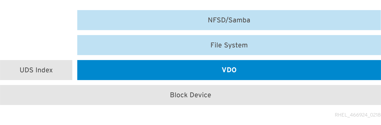
Placement of VDO on iSCSI
You can export the entirety of the VDO storage target as an iSCSI target to remote iSCSI initiators.
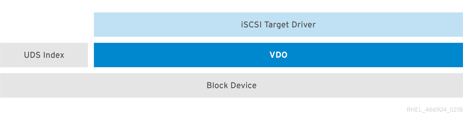
When creating a VDO volume on iSCSI, you can place the VDO volume above or below the iSCSI layer. Although there are many considerations to be made, some guidelines are provided here to help you select the method that best suits your environment.
When placing the VDO volume on the iSCSI server (target) below the iSCSI layer:
- The VDO volume is transparent to the initiator, similar to other iSCSI LUNs. Hiding the thin provisioning and space savings from the client makes the appearance of the LUN easier to monitor and maintain.
- There is decreased network traffic because there are no VDO metadata reads or writes, and read verification for the dedupe advice does not occur across the network.
- The memory and CPU resources being used on the iSCSI target can result in better performance. For example, the ability to host an increased number of hypervisors because the volume reduction is happening on the iSCSI target.
- If the client implements encryption on the initiator and there is a VDO volume below the target, you will not realize any space savings.
When placing the VDO volume on the iSCSI client (initiator) above the iSCSI layer:
- There is a potential for lower network traffic across the network in ASYNC mode if achieving high rates of space savings.
- You can directly view and control the space savings and monitor usage.
-
If you want to encrypt the data, for example, using
dm-crypt, you can implement VDO on top of the crypt and take advantage of space efficiency.
LVM
On more feature-rich systems, you can use LVM to provide multiple logical unit numbers (LUNs) that are all backed by the same deduplicated storage pool.
In the following diagram, the VDO target is registered as a physical volume so that it can be managed by LVM. Multiple logical volumes (LV1 to LV4) are created out of the deduplicated storage pool. In this way, VDO can support multiprotocol unified block or file access to the underlying deduplicated storage pool.
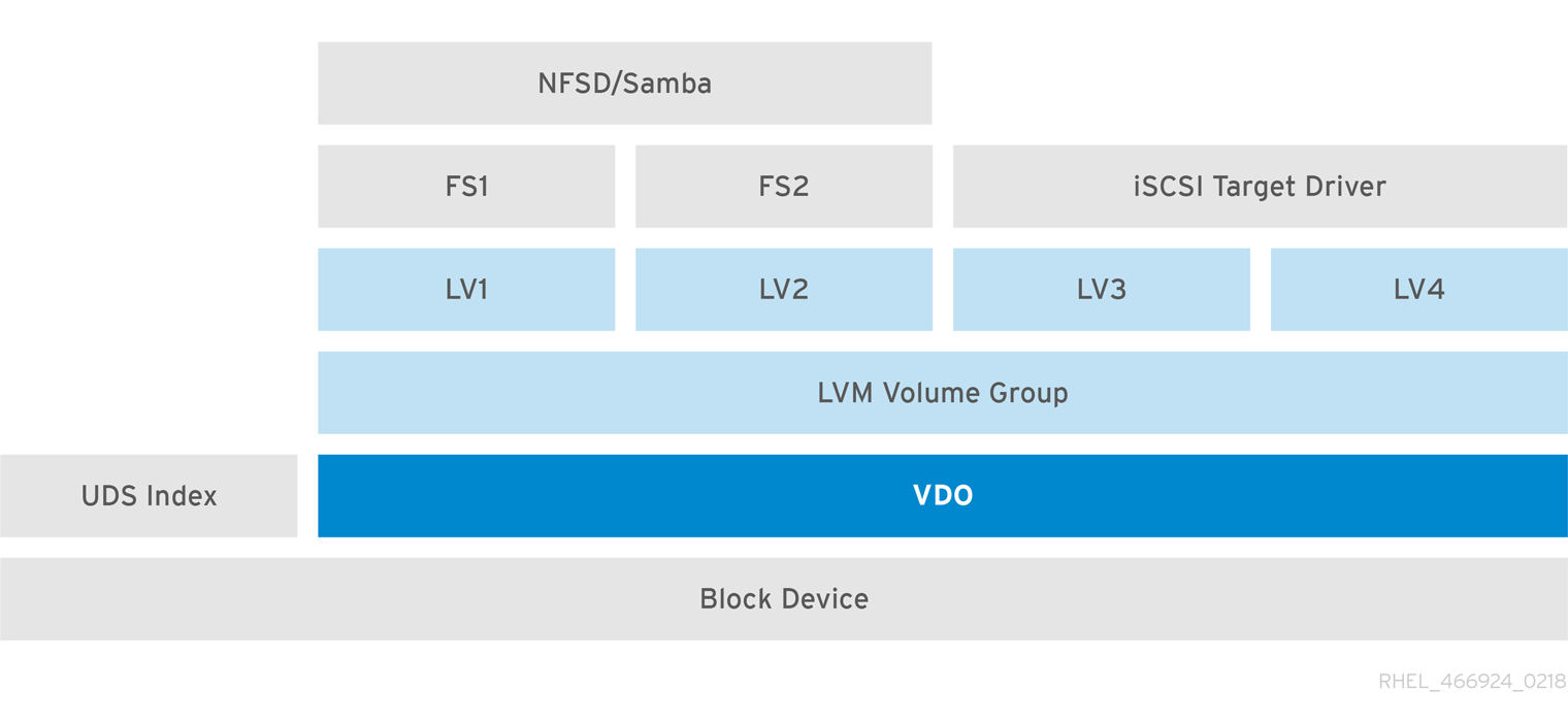
Deduplicated unified storage design enables for multiple file systems to collectively use the same deduplication domain through the LVM tools. Also, file systems can take advantage of LVM snapshot, copy-on-write, and shrink or grow features, all on top of VDO.
Encryption
Device Mapper (DM) mechanisms such as DM Crypt are compatible with VDO. Encrypting VDO volumes helps ensure data security, and any file systems above VDO are still deduplicated.

Applying the encryption layer above VDO results in little if any data deduplication. Encryption makes duplicate blocks different before VDO can deduplicate them.
Always place the encryption layer below VDO.
36.1.3. Components of a VDO volume
VDO uses a block device as a backing store, which can include an aggregation of physical storage consisting of one or more disks, partitions, or even flat files. When a storage management tool creates a VDO volume, VDO reserves volume space for the UDS index and VDO volume. The UDS index and the VDO volume interact together to provide deduplicated block storage.
Figure 36.1. VDO disk organization
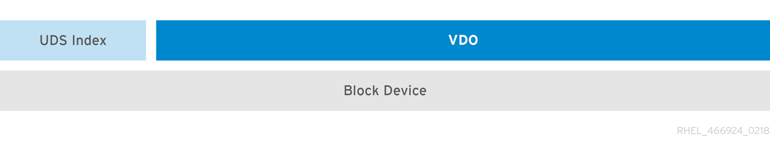
The VDO solution consists of the following components:
kvdoA kernel module that loads into the Linux Device Mapper layer provides a deduplicated, compressed, and thinly provisioned block storage volume.
The
kvdomodule exposes a block device. You can access this block device directly for block storage or present it through a Linux file system, such as XFS or ext4.When
kvdoreceives a request to read a logical block of data from a VDO volume, it maps the requested logical block to the underlying physical block and then reads and returns the requested data.When
kvdoreceives a request to write a block of data to a VDO volume, it first checks whether the request is a DISCARD or TRIM request or whether the data is uniformly zero. If either of these conditions is true,kvdoupdates its block map and acknowledges the request. Otherwise, VDO processes and optimizes the data.udsA kernel module that communicates with the Universal Deduplication Service (UDS) index on the volume and analyzes data for duplicates. For each new piece of data, UDS quickly determines if that piece is identical to any previously stored piece of data. If the index finds a match, the storage system can then internally reference the existing item to avoid storing the same information more than once.
The UDS index runs inside the kernel as the
udskernel module.- Command line tools
- For configuring and managing optimized storage.
36.1.4. The physical and logical size of a VDO volume
VDO utilizes physical, available physical, and logical size in the following ways:
- Physical size
This is the same size as the underlying block device. VDO uses this storage for:
- User data, which might be deduplicated and compressed
- VDO metadata, such as the UDS index
- Available physical size
This is the portion of the physical size that VDO is able to use for user data
It is equivalent to the physical size minus the size of the metadata, minus the remainder after dividing the volume into slabs by the given slab size.
- Logical Size
This is the provisioned size that the VDO volume presents to applications. It is usually larger than the available physical size. If the
--vdoLogicalSizeoption is not specified, then the provisioning of the logical volume is now provisioned to a1:1ratio. For example, if a VDO volume is put on top of a 20 GB block device, then 2.5 GB is reserved for the UDS index (if the default index size is used). The remaining 17.5 GB is provided for the VDO metadata and user data. As a result, the available storage to consume is not more than 17.5 GB, and can be less due to metadata that makes up the actual VDO volume.VDO currently supports any logical size up to 254 times the size of the physical volume with an absolute maximum logical size of 4PB.
Figure 36.2. VDO disk organization
In this figure, the VDO deduplicated storage target sits completely on top of the block device, meaning the physical size of the VDO volume is the same size as the underlying block device.
36.1.5. Slab size in VDO
The physical storage of the VDO volume is divided into a number of slabs. Each slab is a contiguous region of the physical space. All of the slabs for a given volume have the same size, which can be any power of 2 multiple of 128 MB up to 32 GB.
The default slab size is 2 GB to facilitate evaluating VDO on smaller test systems. A single VDO volume can have up to 8192 slabs. Therefore, in the default configuration with 2 GB slabs, the maximum allowed physical storage is 16 TB. When using 32 GB slabs, the maximum allowed physical storage is 256 TB. VDO always reserves at least one entire slab for metadata, and therefore, the reserved slab cannot be used for storing user data.
Slab size has no effect on the performance of the VDO volume.
| Physical volume size | Recommended slab size |
|---|---|
| 10-99 GB | 1 GB |
| 100 GB - 1 TB | 2 GB |
| 2-256 TB | 32 GB |
The minimal disk usage for a VDO volume using default settings of 2 GB slab size and 0.25 dense index, requires approx 4.7 GB. This provides slightly less than 2 GB of physical data to write at 0% deduplication or compression.
Here, the minimal disk usage is the sum of the default slab size and dense index.
You can control the slab size by providing the --vdosettings 'vdo_slab_size_mb=size-in-megabytes' option to the lvcreate command.
36.1.6. VDO requirements
VDO has certain requirements on its placement and your system resources.
36.1.6.1. VDO memory requirements
Each VDO volume has two distinct memory requirements:
- The VDO module
VDO requires a fixed 38 MB of RAM and several variable amounts:
- 1.15 MB of RAM for each 1 MB of configured block map cache size. The block map cache requires a minimum of 150 MB of RAM.
- 1.6 MB of RAM for each 1 TB of logical space.
- 268 MB of RAM for each 1 TB of physical storage managed by the volume.
- The UDS index
The Universal Deduplication Service (UDS) requires a minimum of 250 MB of RAM, which is also the default amount that deduplication uses. You can configure the value when formatting a VDO volume, because the value also affects the amount of storage that the index needs.
The memory required for the UDS index is determined by the index type and the required size of the deduplication window. The deduplication window is the amount of previously written data that VDO can check for matching blocks.
Expand Index type Deduplication window Dense
1 TB per 1 GB of RAM
Sparse
10 TB per 1 GB of RAM
NoteThe minimal disk usage for a VDO volume using default settings of 2 GB slab size and 0.25 dense index, requires approx 4.7 GB. This provides slightly less than 2 GB of physical data to write at 0% deduplication or compression.
Here, the minimal disk usage is the sum of the default slab size and dense index.
36.1.6.2. VDO storage space requirements
You can configure a VDO volume to use up to 256 TB of physical storage. Only a certain part of the physical storage is usable to store data.
VDO requires storage for two types of VDO metadata and for the UDS index. Use the following calculations to determine the usable size of a VDO-managed volume:
- The first type of VDO metadata uses approximately 1 MB for each 4 GB of physical storage plus an additional 1 MB per slab.
- The second type of VDO metadata consumes approximately 1.25 MB for each 1 GB of logical storage, rounded up to the nearest slab.
- The amount of storage required for the UDS index depends on the type of index and the amount of RAM allocated to the index. For each 1 GB of RAM, a dense UDS index uses 17 GB of storage, and a sparse UDS index will use 170 GB of storage.
36.1.6.3. Placement of VDO in the storage stack
Place storage layers either above, or under the Virtual Data Optimizer (VDO), to fit the placement requirements.
A VDO volume is a thin-provisioned block device. You can prevent running out of physical space by placing the volume above a storage layer that you can expand at a later time. Examples of such expandable storage are Logical Volume Manager (LVM) volumes, or Multiple Device Redundant Array Inexpensive or Independent Disks (MD RAID) arrays.
You can place thick provisioned layers above VDO. There are two aspects of thick provisioned layers that you must consider:
- Writing new data to unused logical space on a thick device. When using VDO, or other thin-provisioned storage, the device can report that it is out of space during this kind of write.
- Overwriting used logical space on a thick device with new data. When using VDO, overwriting data can also result in a report of the device being out of space.
These limitations affect all layers above the VDO layer. If you do not monitor the VDO device, you can unexpectedly run out of physical space on the thick-provisioned volumes above VDO.
See the following examples of supported and unsupported VDO volume configurations.
Figure 36.3. Supported VDO volume configurations
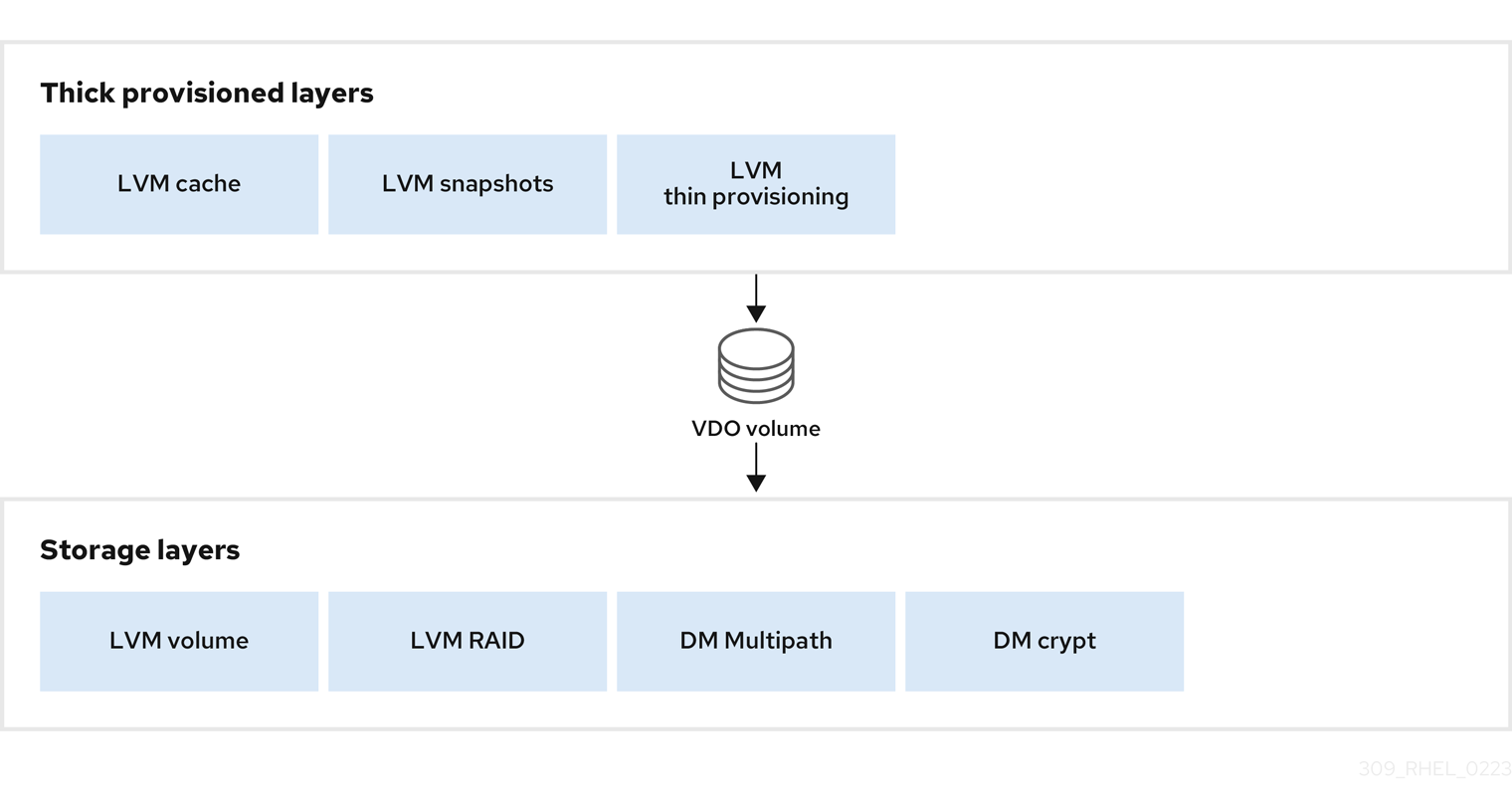
Figure 36.4. Unsupported VDO volume configurations
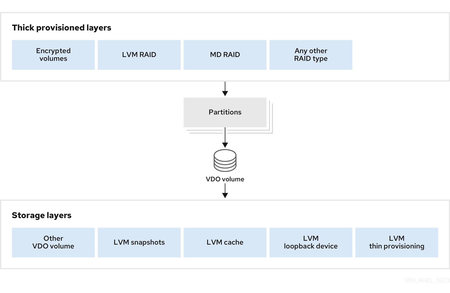
36.1.6.4. Examples of VDO requirements by physical size
The following tables provide approximate system requirements of VDO based on the physical size of the underlying volume. Each table lists requirements appropriate to the intended deployment, such as primary storage or backup storage.
The exact numbers depend on your configuration of the VDO volume.
- Primary storage deployment
In the primary storage case, the UDS index is between 0.01% to 25% the size of the physical size.
Expand Table 36.2. Examples of storage and memory configurations for primary storage Physical size RAM usage: UDS RAM usage: VDO Disk usage Index type 1 TB
250 MB
472 MB
2.5 GB
Dense
10 TB
1 GB
3 GB
10 GB
Dense
250 MB
22 GB
Sparse
50 TB
1 GB
14 GB
85 GB
Sparse
100 TB
3 GB
27 GB
255 GB
Sparse
256 TB
5 GB
69 GB
425 GB
Sparse
- Backup storage deployment
In the backup storage case, the deduplication window must be larger than the backup set. If you expect the backup set or the physical size to grow in the future, factor this into the index size.
Expand Table 36.3. Examples of storage and memory configurations for backup storage Deduplication window RAM usage: UDS Disk usage Index type 1 TB
250 MB
2.5 GB
Dense
10 TB
2 GB
21 GB
Dense
50 TB
2 GB
170 GB
Sparse
100 TB
4 GB
340 GB
Sparse
256 TB
8 GB
700 GB
Sparse
36.1.7. Installing VDO
You can install the VDO software necessary to create, mount, and manage VDO volumes.
Procedure
Install the VDO software:
# yum install lvm2 kmod-kvdo vdo
36.1.8. Creating a VDO volume
This procedure creates a VDO volume on a block device.
Prerequisites
- Install the VDO software. See Section 36.1.7, “Installing VDO”.
- Use expandable storage as the backing block device. For more information, see Section 36.1.6.3, “Placement of VDO in the storage stack”.
Procedure
In all the following steps, replace vdo-name with the identifier you want to use for your VDO volume; for example, vdo1. You must use a different name and device for each instance of VDO on the system.
Find a persistent name for the block device where you want to create the VDO volume. For more information about persistent names, see Chapter 26, Overview of persistent naming attributes.
If you use a non-persistent device name, then VDO might fail to start properly in the future if the device name changes.
Create the VDO volume:
# vdo create \ --name=vdo-name \ --device=block-device \ --vdoLogicalSize=logical-size-
Replace block-device with the persistent name of the block device where you want to create the VDO volume. For example,
/dev/disk/by-id/scsi-3600508b1001c264ad2af21e903ad031f. Replace logical-size with the amount of logical storage that the VDO volume should present:
-
For active VMs or container storage, use logical size that is ten times the physical size of your block device. For example, if your block device is 1TB in size, use
10There. -
For object storage, use logical size that is three times the physical size of your block device. For example, if your block device is 1TB in size, use
3There.
-
For active VMs or container storage, use logical size that is ten times the physical size of your block device. For example, if your block device is 1TB in size, use
If the physical block device is larger than 16TiB, add the
--vdoSlabSize=32Goption to increase the slab size on the volume to 32GiB.Using the default slab size of 2GiB on block devices larger than 16TiB results in the
vdo createcommand failing with the following error:vdo: ERROR - vdoformat: formatVDO failed on '/dev/device': VDO Status: Exceeds maximum number of slabs supported
Example 36.1. Creating VDO for container storage
For example, to create a VDO volume for container storage on a 1TB block device, you might use:
# vdo create \ --name=vdo1 \ --device=/dev/disk/by-id/scsi-3600508b1001c264ad2af21e903ad031f \ --vdoLogicalSize=10TImportantIf a failure occurs when creating the VDO volume, remove the volume to clean up. See Removing an unsuccessfully created VDO volume for details.
-
Replace block-device with the persistent name of the block device where you want to create the VDO volume. For example,
Create a file system on top of the VDO volume:
For the XFS file system:
# mkfs.xfs -K /dev/mapper/vdo-nameFor the ext4 file system:
# mkfs.ext4 -E nodiscard /dev/mapper/vdo-nameNoteThe purpose of the
-Kand-E nodiscardoptions on a freshly created VDO volume is to not spend time sending requests, as it has no effect on an un-allocated block. A fresh VDO volume starts out 100% un-allocated.
Use the following command to wait for the system to register the new device node:
# udevadm settle
Next steps
- Mount the file system. See Section 36.1.9, “Mounting a VDO volume” for details.
-
Enable the
discardfeature for the file system on your VDO device. See Section 36.1.10, “Enabling periodic block discard” for details.
36.1.9. Mounting a VDO volume
This procedure mounts a file system on a VDO volume, either manually or persistently.
Prerequisites
- A VDO volume has been created on your system. For instructions, see Section 36.1.8, “Creating a VDO volume”.
Procedure
To mount the file system on the VDO volume manually, use:
# mount /dev/mapper/vdo-name mount-pointTo configure the file system to mount automatically at boot, add a line to the
/etc/fstabfile:For the XFS file system:
/dev/mapper/vdo-name mount-point xfs defaults 0 0For the ext4 file system:
/dev/mapper/vdo-name mount-point ext4 defaults 0 0
If the VDO volume is located on a block device that requires network, such as iSCSI, add the
_netdevmount option.
36.1.10. Enabling periodic block discard
You can enable a systemd timer to regularly discard unused blocks on all supported file systems.
Procedure
Enable and start the
systemdtimer:# systemctl enable --now fstrim.timer Created symlink /etc/systemd/system/timers.target.wants/fstrim.timer → /usr/lib/systemd/system/fstrim.timer.
Verification
Verify the status of the timer:
# systemctl status fstrim.timer fstrim.timer - Discard unused blocks once a week Loaded: loaded (/usr/lib/systemd/system/fstrim.timer; enabled; vendor preset: disabled) Active: active (waiting) since Wed 2023-05-17 13:24:41 CEST; 3min 15s ago Trigger: Mon 2023-05-22 01:20:46 CEST; 4 days left Docs: man:fstrim May 17 13:24:41 localhost.localdomain systemd[1]: Started Discard unused blocks once a week.
36.1.11. Monitoring VDO
This procedure describes how to obtain usage and efficiency information from a VDO volume.
Prerequisites
- Install the VDO software. See Installing VDO.
Procedure
Use the
vdostatsutility to get information about a VDO volume:# vdostats --human-readable Device 1K-blocks Used Available Use% Space saving% /dev/mapper/node1osd1 926.5G 21.0G 905.5G 2% 73% /dev/mapper/node1osd2 926.5G 28.2G 898.3G 3% 64%
36.2. Maintaining VDO
After deploying a VDO volume, you can perform certain tasks to maintain or optimize it. Some of the following tasks are required for the correct functioning of VDO volumes.
Prerequisites
- VDO is installed and deployed. See Section 36.1, “Deploying VDO”.
36.2.1. Managing free space on VDO volumes
VDO is a thinly provisioned block storage target. Because of that, you must actively monitor and manage space usage on VDO volumes.
36.2.1.1. The physical and logical size of a VDO volume
VDO utilizes physical, available physical, and logical size in the following ways:
- Physical size
This is the same size as the underlying block device. VDO uses this storage for:
- User data, which might be deduplicated and compressed
- VDO metadata, such as the UDS index
- Available physical size
This is the portion of the physical size that VDO is able to use for user data
It is equivalent to the physical size minus the size of the metadata, minus the remainder after dividing the volume into slabs by the given slab size.
- Logical Size
This is the provisioned size that the VDO volume presents to applications. It is usually larger than the available physical size. If the
--vdoLogicalSizeoption is not specified, then the provisioning of the logical volume is now provisioned to a1:1ratio. For example, if a VDO volume is put on top of a 20 GB block device, then 2.5 GB is reserved for the UDS index (if the default index size is used). The remaining 17.5 GB is provided for the VDO metadata and user data. As a result, the available storage to consume is not more than 17.5 GB, and can be less due to metadata that makes up the actual VDO volume.VDO currently supports any logical size up to 254 times the size of the physical volume with an absolute maximum logical size of 4PB.
Figure 36.5. VDO disk organization
In this figure, the VDO deduplicated storage target sits completely on top of the block device, meaning the physical size of the VDO volume is the same size as the underlying block device.
36.2.1.2. Thin provisioning in VDO
VDO is a thinly provisioned block storage target. The amount of physical space that a VDO volume uses might differ from the size of the volume that is presented to users of the storage. You can make use of this disparity to save on storage costs.
Out-of-space conditions
Take care to avoid unexpectedly running out of storage space, if the data written does not achieve the expected rate of optimization.
Whenever the number of logical blocks (virtual storage) exceeds the number of physical blocks (actual storage), it becomes possible for file systems and applications to unexpectedly run out of space. For that reason, storage systems using VDO must provide you with a way of monitoring the size of the free pool on the VDO volume.
You can determine the size of this free pool by using the vdostats utility. The default output of this utility lists information for all running VDO volumes in a format similar to the Linux df utility. For example:
Device 1K-blocks Used Available Use%
/dev/mapper/vdo-name 211812352 105906176 105906176 50%When the physical storage capacity of a VDO volume is almost full, VDO reports a warning in the system log, similar to the following:
Oct 2 17:13:39 system lvm[13863]: Monitoring VDO pool vdo-name.
Oct 2 17:27:39 system lvm[13863]: WARNING: VDO pool vdo-name is now 80.69% full.
Oct 2 17:28:19 system lvm[13863]: WARNING: VDO pool vdo-name is now 85.25% full.
Oct 2 17:29:39 system lvm[13863]: WARNING: VDO pool vdo-name is now 90.64% full.
Oct 2 17:30:29 system lvm[13863]: WARNING: VDO pool vdo-name is now 96.07% full.
These warning messages appear only when the lvm2-monitor service is running. It is enabled by default.
How to prevent out-of-space conditions
If the size of free pool drops below a certain level, you can take action by:
- Deleting data. This reclaims space whenever the deleted data is not duplicated. Deleting data frees the space only after discards are issued.
- Adding physical storage
Monitor physical space on your VDO volumes to prevent out-of-space situations. Running out of physical blocks might result in losing recently written, unacknowledged data on the VDO volume.
Thin provisioning and the TRIM and DISCARD commands
To benefit from the storage savings of thin provisioning, the physical storage layer needs to know when data is deleted. File systems that work with thinly provisioned storage send TRIM or DISCARD commands to inform the storage system when a logical block is no longer required.
Several methods of sending the TRIM or DISCARD commands are available:
-
With the
discardmount option, the file systems can send these commands whenever a block is deleted. -
You can send the commands in a controlled manner by using utilities such as
fstrim. These utilities tell the file system to detect which logical blocks are unused and send the information to the storage system in the form of aTRIMorDISCARDcommand.
The need to use TRIM or DISCARD on unused blocks is not unique to VDO. Any thinly provisioned storage system has the same challenge.
36.2.1.3. Monitoring VDO
This procedure describes how to obtain usage and efficiency information from a VDO volume.
Prerequisites
- Install the VDO software. See Installing VDO.
Procedure
Use the
vdostatsutility to get information about a VDO volume:# vdostats --human-readable Device 1K-blocks Used Available Use% Space saving% /dev/mapper/node1osd1 926.5G 21.0G 905.5G 2% 73% /dev/mapper/node1osd2 926.5G 28.2G 898.3G 3% 64%
36.2.1.4. Reclaiming space for VDO on file systems
This procedure reclaims storage space on a VDO volume that hosts a file system.
VDO cannot reclaim space unless file systems communicate that blocks are free using the DISCARD, TRIM, or UNMAP commands.
Procedure
- If the file system on your VDO volume supports discard operations, enable them. See Discarding unused blocks.
-
For file systems that do not use
DISCARD,TRIM, orUNMAP, you can manually reclaim free space. Store a file consisting of binary zeros to fill the free space and then delete that file.
36.2.1.5. Reclaiming space for VDO without a file system
This procedure reclaims storage space on a VDO volume that is used as a block storage target without a file system.
Procedure
Use the
blkdiscardutility.For example, a single VDO volume can be carved up into multiple subvolumes by deploying LVM on top of it. Before deprovisioning a logical volume, use the
blkdiscardutility to free the space previously used by that logical volume.LVM supports the
REQ_DISCARDcommand and forwards the requests to VDO at the appropriate logical block addresses in order to free the space. If you use other volume managers, they also need to supportREQ_DISCARD, or equivalently,UNMAPfor SCSI devices orTRIMfor ATA devices.
36.2.1.6. Reclaiming space for VDO on Fibre Channel or Ethernet network
This procedure reclaims storage space on VDO volumes (or portions of volumes) that are provisioned to hosts on a Fibre Channel storage fabric or an Ethernet network using SCSI target frameworks such as LIO or SCST.
Procedure
SCSI initiators can use the
UNMAPcommand to free space on thinly provisioned storage targets, but the SCSI target framework needs to be configured to advertise support for this command. This is typically done by enabling thin provisioning on these volumes.Verify support for
UNMAPon Linux-based SCSI initiators by running the following command:# sg_vpd --page=0xb0 /dev/deviceIn the output, verify that the Maximum unmap LBA count value is greater than zero.
36.2.2. Starting or stopping VDO volumes
You can start or stop a given VDO volume, or all VDO volumes, and their associated UDS indexes.
36.2.2.1. Started and activated VDO volumes
During the system boot, the vdo systemd unit automatically starts all VDO devices that are configured as activated.
The vdo systemd unit is installed and enabled by default when the vdo package is installed. This unit automatically runs the vdo start --all command at system startup to bring up all activated VDO volumes.
You can also create a VDO volume that does not start automatically by adding the --activate=disabled option to the vdo create command.
The starting order
Some systems might place LVM volumes both above VDO volumes and below them. On these systems, it is necessary to start services in the right order:
- The lower layer of LVM must start first. In most systems, starting this layer is configured automatically when the LVM package is installed.
-
The
vdosystemdunit must start then. - Finally, additional scripts must run in order to start LVM volumes or other services on top of the running VDO volumes.
How long it takes to stop a volume
Stopping a VDO volume takes time based on the speed of your storage device and the amount of data that the volume needs to write:
- The volume always writes around 1GiB for every 1GiB of the UDS index.
- The volume additionally writes the amount of data equal to the block map cache size plus up to 8MiB per slab.
- The volume must finish processing all outstanding IO requests.
36.2.2.2. Starting a VDO volume
This procedure starts a given VDO volume or all VDO volumes on your system.
Procedure
To start a given VDO volume, use:
# vdo start --name=my-vdoTo start all VDO volumes, use:
# vdo start --all
36.2.2.3. Stopping a VDO volume
This procedure stops a given VDO volume or all VDO volumes on your system.
Procedure
Stop the volume.
To stop a given VDO volume, use:
# vdo stop --name=my-vdoTo stop all VDO volumes, use:
# vdo stop --all
- Wait for the volume to finish writing data to the disk.
36.2.3. Automatically starting VDO volumes at system boot
You can configure VDO volumes so that they start automatically at system boot. You can also disable the automatic start.
36.2.3.1. Started and activated VDO volumes
During the system boot, the vdo systemd unit automatically starts all VDO devices that are configured as activated.
The vdo systemd unit is installed and enabled by default when the vdo package is installed. This unit automatically runs the vdo start --all command at system startup to bring up all activated VDO volumes.
You can also create a VDO volume that does not start automatically by adding the --activate=disabled option to the vdo create command.
The starting order
Some systems might place LVM volumes both above VDO volumes and below them. On these systems, it is necessary to start services in the right order:
- The lower layer of LVM must start first. In most systems, starting this layer is configured automatically when the LVM package is installed.
-
The
vdosystemdunit must start then. - Finally, additional scripts must run in order to start LVM volumes or other services on top of the running VDO volumes.
How long it takes to stop a volume
Stopping a VDO volume takes time based on the speed of your storage device and the amount of data that the volume needs to write:
- The volume always writes around 1GiB for every 1GiB of the UDS index.
- The volume additionally writes the amount of data equal to the block map cache size plus up to 8MiB per slab.
- The volume must finish processing all outstanding IO requests.
36.2.3.2. Activating a VDO volume
This procedure activates a VDO volume to enable it to start automatically.
Procedure
To activate a specific volume:
# vdo activate --name=my-vdoTo activate all volumes:
# vdo activate --all
36.2.3.3. Deactivating a VDO volume
This procedure deactivates a VDO volume to prevent it from starting automatically.
Procedure
To deactivate a specific volume:
# vdo deactivate --name=my-vdoTo deactivate all volumes:
# vdo deactivate --all
36.2.4. Selecting a VDO write mode
You can configure write mode for a VDO volume, based on what the underlying block device requires. By default, VDO selects write mode automatically.
36.2.4.1. VDO write modes
VDO supports the following write modes:
syncWhen VDO is in
syncmode, the layers above it assume that a write command writes data to persistent storage. As a result, it is not necessary for the file system or application, for example, to issue FLUSH or force unit access (FUA) requests to cause the data to become persistent at critical points.VDO must be set to
syncmode only when the underlying storage guarantees that data is written to persistent storage when the write command completes. That is, the storage must either have no volatile write cache, or have a write through cache.asyncWhen VDO is in
asyncmode, VDO does not guarantee that the data is written to persistent storage when a write command is acknowledged. The file system or application must issue FLUSH or FUA requests to ensure data persistence at critical points in each transaction.VDO must be set to
asyncmode if the underlying storage does not guarantee that data is written to persistent storage when the write command completes; that is, when the storage has a volatile write back cache.async-unsafeThis mode has the same properties as
asyncbut it is not compliant with Atomicity, Consistency, Isolation, Durability (ACID). Compared toasync,async-unsafehas a better performance.WarningWhen an application or a file system that assumes ACID compliance operates on top of the VDO volume,
async-unsafemode might cause unexpected data loss.auto-
The
automode automatically selectssyncorasyncbased on the characteristics of each device. This is the default option.
36.2.4.2. The internal processing of VDO write modes
The write modes for VDO are sync and async. The following information describes the operations of these modes.
If the kvdo module is operating in synchronous (synch) mode:
- It temporarily writes the data in the request to the allocated block and then acknowledges the request.
- Once the acknowledgment is complete, an attempt is made to deduplicate the block by computing a MurmurHash-3 signature of the block data, which is sent to the VDO index.
-
If the VDO index contains an entry for a block with the same signature,
kvdoreads the indicated block and does a byte-by-byte comparison of the two blocks to verify that they are identical. -
If they are indeed identical, then
kvdoupdates its block map so that the logical block points to the corresponding physical block and releases the allocated physical block. -
If the VDO index did not contain an entry for the signature of the block being written, or the indicated block does not actually contain the same data,
kvdoupdates its block map to make the temporary physical block permanent.
If kvdo is operating in asynchronous (async) mode:
- Instead of writing the data, it will immediately acknowledge the request.
- It will then attempt to deduplicate the block in same manner as described above.
-
If the block turns out to be a duplicate,
kvdoupdates its block map and releases the allocated block. Otherwise, it writes the data in the request to the allocated block and updates the block map to make the physical block permanent.
36.2.4.3. Checking the write mode on a VDO volume
This procedure lists the active write mode on a selected VDO volume.
Procedure
Use the following command to see the write mode used by a VDO volume:
# vdo status --name=my-vdoThe output lists:
-
The configured write policy, which is the option selected from
sync,async, orauto -
The write policy, which is the particular write mode that VDO applied, that is either
syncorasync
-
The configured write policy, which is the option selected from
36.2.4.4. Checking for a volatile cache
This procedure determines if a block device has a volatile cache or not. You can use the information to choose between the sync and async VDO write modes.
Procedure
Use either of the following methods to determine if a device has a writeback cache:
Read the
/sys/block/block-device/device/scsi_disk/identifier/cache_typesysfsfile. For example:$ cat '/sys/block/sda/device/scsi_disk/7:0:0:0/cache_type' write back$ cat '/sys/block/sdb/device/scsi_disk/1:2:0:0/cache_type' NoneAlternatively, you can find whether the above mentioned devices have a write cache or not in the kernel boot log:
sd 7:0:0:0: [sda] Write cache: enabled, read cache: enabled, does not support DPO or FUA sd 1:2:0:0: [sdb] Write cache: disabled, read cache: disabled, supports DPO and FUA
In the previous examples:
-
Device
sdaindicates that it has a writeback cache. Useasyncmode for it. -
Device
sdbindicates that it does not have a writeback cache. Usesyncmode for it.
You should configure VDO to use the
syncwrite mode if thecache_typevalue isNoneorwrite through.-
Device
36.2.4.5. Setting a VDO write mode
This procedure sets a write mode for a VDO volume, either for an existing one or when creating a new volume.
Using an incorrect write mode might result in data loss after a power failure, a system crash, or any unexpected loss of contact with the disk.
Prerequisites
- Determine which write mode is correct for your device. See Section 36.2.4.4, “Checking for a volatile cache”.
Procedure
You can set a write mode either on an existing VDO volume or when creating a new volume:
To modify an existing VDO volume, use:
# vdo changeWritePolicy --writePolicy=sync|async|async-unsafe|auto \ --name=vdo-name-
To specify a write mode when creating a VDO volume, add the
--writePolicy=sync|async|async-unsafe|autooption to thevdo createcommand.
36.2.5. Recovering a VDO volume after an unclean shutdown
You can recover a VDO volume after an unclean shutdown to enable it to continue operating. The task is mostly automated. Additionally, you can clean up after a VDO volume was unsuccessfully created because of a failure in the process.
36.2.5.1. VDO write modes
VDO supports the following write modes:
syncWhen VDO is in
syncmode, the layers above it assume that a write command writes data to persistent storage. As a result, it is not necessary for the file system or application, for example, to issue FLUSH or force unit access (FUA) requests to cause the data to become persistent at critical points.VDO must be set to
syncmode only when the underlying storage guarantees that data is written to persistent storage when the write command completes. That is, the storage must either have no volatile write cache, or have a write through cache.asyncWhen VDO is in
asyncmode, VDO does not guarantee that the data is written to persistent storage when a write command is acknowledged. The file system or application must issue FLUSH or FUA requests to ensure data persistence at critical points in each transaction.VDO must be set to
asyncmode if the underlying storage does not guarantee that data is written to persistent storage when the write command completes; that is, when the storage has a volatile write back cache.async-unsafeThis mode has the same properties as
asyncbut it is not compliant with Atomicity, Consistency, Isolation, Durability (ACID). Compared toasync,async-unsafehas a better performance.WarningWhen an application or a file system that assumes ACID compliance operates on top of the VDO volume,
async-unsafemode might cause unexpected data loss.auto-
The
automode automatically selectssyncorasyncbased on the characteristics of each device. This is the default option.
36.2.5.2. VDO volume recovery
When a VDO volume restarts after an unclean shutdown, VDO performs the following actions:
- Verifies the consistency of the metadata on the volume.
- Rebuilds a portion of the metadata to repair it if necessary.
Rebuilds are automatic and do not require user intervention.
VDO might rebuild different writes depending on the active write mode:
sync-
If VDO was running on synchronous storage and write policy was set to
sync, all data written to the volume are fully recovered. async-
If the write policy was
async, some writes might not be recovered if they were not made durable. This is done by sending VDO aFLUSHcommand or a write I/O tagged with the FUA (force unit access) flag. You can accomplish this from user mode by invoking a data integrity operation likefsync,fdatasync,sync, orumount.
In either mode, some writes that were either unacknowledged or not followed by a flush might also be rebuilt.
Automatic and manual recovery
When a VDO volume enters recovering operating mode, VDO automatically rebuilds the unclean VDO volume after the it comes back online. This is called online recovery.
If VDO cannot recover a VDO volume successfully, it places the volume in read-only operating mode that persists across volume restarts. You need to fix the problem manually by forcing a rebuild.
36.2.5.3. VDO operating modes
This section describes the modes that indicate whether a VDO volume is operating normally or is recovering from an error.
You can display the current operating mode of a VDO volume using the vdostats --verbose device command. See the Operating mode attribute in the output.
normal-
This is the default operating mode. VDO volumes are always in
normalmode, unless either of the following states forces a different mode. A newly created VDO volume starts innormalmode. recoveringWhen a VDO volume does not save all of its metadata before shutting down, it automatically enters
recoveringmode the next time that it starts up. The typical reasons for entering this mode are sudden power loss or a problem from the underlying storage device.In
recoveringmode, VDO is fixing the references counts for each physical block of data on the device. Recovery usually does not take very long. The time depends on how large the VDO volume is, how fast the underlying storage device is, and how many other requests VDO is handling simultaneously. The VDO volume functions normally with the following exceptions:- Initially, the amount of space available for write requests on the volume might be limited. As more of the metadata is recovered, more free space becomes available.
- Data written while the VDO volume is recovering might fail to deduplicate against data written before the crash if that data is in a portion of the volume that has not yet been recovered. VDO can compress data while recovering the volume. You can still read or overwrite compressed blocks.
- During an online recovery, certain statistics are unavailable: for example, blocks in use and blocks free. These statistics become available when the rebuild is complete.
- Response times for reads and writes might be slower than usual due to the ongoing recovery work
You can safely shut down the VDO volume in
recoveringmode. If the recovery does not finish before shutting down, the device entersrecoveringmode again the next time that it starts up.The VDO volume automatically exits
recoveringmode and moves tonormalmode when it has fixed all the reference counts. No administrator action is necessary. For details, see Section 36.2.5.4, “Recovering a VDO volume online”.read-onlyWhen a VDO volume encounters a fatal internal error, it enters
read-onlymode. Events that might causeread-onlymode include metadata corruption or the backing storage device becoming read-only. This mode is an error state.In
read-onlymode, data reads work normally but data writes always fail. The VDO volume stays inread-onlymode until an administrator fixes the problem.You can safely shut down a VDO volume in
read-onlymode. The mode usually persists after the VDO volume is restarted. In rare cases, the VDO volume is not able to record theread-onlystate to the backing storage device. In these cases, VDO attempts to do a recovery instead.Once a volume is in read-only mode, there is no guarantee that data on the volume has not been lost or corrupted. In such cases, Red Hat recommends copying the data out of the read-only volume and possibly restoring the volume from backup.
If the risk of data corruption is acceptable, it is possible to force an offline rebuild of the VDO volume metadata so the volume can be brought back online and made available. The integrity of the rebuilt data cannot be guaranteed. For details, see Section 36.2.5.5, “Forcing an offline rebuild of a VDO volume metadata”.
36.2.5.4. Recovering a VDO volume online
This procedure performs an online recovery on a VDO volume to recover metadata after an unclean shutdown.
Procedure
If the VDO volume is not already started, start it:
# vdo start --name=my-vdoNo additional steps are necessary. The recovery runs in the background.
- If you rely on volume statistics like blocks in use and blocks free, wait until they are available.
36.2.5.5. Forcing an offline rebuild of a VDO volume metadata
This procedure performs a forced offline rebuild of a VDO volume metadata to recover after an unclean shutdown.
This procedure might cause data loss on the volume.
Prerequisites
- The VDO volume is started.
Procedure
Check if the volume is in read-only mode. See the operating mode attribute in the command output:
# vdo status --name=my-vdoIf the volume is not in read-only mode, it is not necessary to force an offline rebuild. Perform an online recovery as described in Section 36.2.5.4, “Recovering a VDO volume online”.
Stop the volume if it is running:
# vdo stop --name=my-vdoRestart the volume with the
--forceRebuildoption:# vdo start --name=my-vdo --forceRebuild
36.2.5.6. Removing an unsuccessfully created VDO volume
This procedure cleans up a VDO volume in an intermediate state. A volume is left in an intermediate state if a failure occurs when creating the volume. This might happen when, for example:
- The system crashes
- Power fails
-
The administrator interrupts a running
vdo createcommand
Procedure
To clean up, remove the unsuccessfully created volume with the
--forceoption:# vdo remove --force --name=my-vdoThe
--forceoption is required because the administrator might have caused a conflict by changing the system configuration since the volume was unsuccessfully created.Without the
--forceoption, thevdo removecommand fails with the following message:[...] A previous operation failed. Recovery from the failure either failed or was interrupted. Add '--force' to 'remove' to perform the following cleanup. Steps to clean up VDO my-vdo: umount -f /dev/mapper/my-vdo udevadm settle dmsetup remove my-vdo vdo: ERROR - VDO volume my-vdo previous operation (create) is incomplete
36.2.6. Optimizing the UDS index
You can configure certain settings of the UDS index to optimize it on your system.
You cannot change the properties of the UDS index after creating the VDO volume.
36.2.6.1. Components of a VDO volume
VDO uses a block device as a backing store, which can include an aggregation of physical storage consisting of one or more disks, partitions, or even flat files. When a storage management tool creates a VDO volume, VDO reserves volume space for the UDS index and VDO volume. The UDS index and the VDO volume interact together to provide deduplicated block storage.
Figure 36.6. VDO disk organization
The VDO solution consists of the following components:
kvdoA kernel module that loads into the Linux Device Mapper layer provides a deduplicated, compressed, and thinly provisioned block storage volume.
The
kvdomodule exposes a block device. You can access this block device directly for block storage or present it through a Linux file system, such as XFS or ext4.When
kvdoreceives a request to read a logical block of data from a VDO volume, it maps the requested logical block to the underlying physical block and then reads and returns the requested data.When
kvdoreceives a request to write a block of data to a VDO volume, it first checks whether the request is a DISCARD or TRIM request or whether the data is uniformly zero. If either of these conditions is true,kvdoupdates its block map and acknowledges the request. Otherwise, VDO processes and optimizes the data.udsA kernel module that communicates with the Universal Deduplication Service (UDS) index on the volume and analyzes data for duplicates. For each new piece of data, UDS quickly determines if that piece is identical to any previously stored piece of data. If the index finds a match, the storage system can then internally reference the existing item to avoid storing the same information more than once.
The UDS index runs inside the kernel as the
udskernel module.- Command line tools
- For configuring and managing optimized storage.
36.2.6.2. The UDS index
VDO uses a high-performance deduplication index called UDS to detect duplicate blocks of data as they are being stored.
The UDS index provides the foundation of the VDO product. For each new piece of data, it quickly determines if that piece is identical to any previously stored piece of data. If the index finds match, the storage system can then internally reference the existing item to avoid storing the same information more than once.
The UDS index runs inside the kernel as the uds kernel module.
The deduplication window is the number of previously written blocks that the index remembers. The size of the deduplication window is configurable. For a given window size, the index requires a specific amount of RAM and a specific amount of disk space. The size of the window is usually determined by specifying the size of the index memory using the --indexMem=size option. VDO then determines the amount of disk space to use automatically.
The UDS index consists of two parts:
- A compact representation is used in memory that contains at most one entry per unique block.
- An on-disk component that records the associated block names presented to the index as they occur, in order.
UDS uses an average of 4 bytes per entry in memory, including cache.
The on-disk component maintains a bounded history of data passed to UDS. UDS provides deduplication advice for data that falls within this deduplication window, containing the names of the most recently seen blocks. The deduplication window allows UDS to index data as efficiently as possible while limiting the amount of memory required to index large data repositories. Despite the bounded nature of the deduplication window, most datasets which have high levels of deduplication also exhibit a high degree of temporal locality - in other words, most deduplication occurs among sets of blocks that were written at about the same time. Furthermore, in general, data being written is more likely to duplicate data that was recently written than data that was written a long time ago. Therefore, for a given workload over a given time interval, deduplication rates will often be the same whether UDS indexes only the most recent data or all the data.
Because duplicate data tends to exhibit temporal locality, it is rarely necessary to index every block in the storage system. Were this not so, the cost of index memory would outstrip the savings of reduced storage costs from deduplication. Index size requirements are more closely related to the rate of data ingestion. For example, consider a storage system with 100 TB of total capacity but with an ingestion rate of 1 TB per week. With a deduplication window of 4 TB, UDS can detect most redundancy among the data written within the last month.
36.2.6.3. Recommended UDS index configuration
This section describes the recommended options to use with the UDS index, based on your intended use case.
In general, Red Hat recommends using a sparse UDS index for all production use cases. This is an extremely efficient indexing data structure, requiring approximately one-tenth of a byte of RAM per block in its deduplication window. On disk, it requires approximately 72 bytes of disk space per block. The minimum configuration of this index uses 256 MB of RAM and approximately 25 GB of space on disk.
To use this configuration, specify the --sparseIndex=enabled --indexMem=0.25 options to the vdo create command. This configuration results in a deduplication window of 2.5 TB (meaning it will remember a history of 2.5 TB). For most use cases, a deduplication window of 2.5 TB is appropriate for deduplicating storage pools that are up to 10 TB in size.
The default configuration of the index, however, is to use a dense index. This index is considerably less efficient (by a factor of 10) in RAM, but it has much lower (also by a factor of 10) minimum required disk space, making it more convenient for evaluation in constrained environments.
In general, a deduplication window that is one quarter of the physical size of a VDO volume is a recommended configuration. However, this is not an actual requirement. Even small deduplication windows (compared to the amount of physical storage) can find significant amounts of duplicate data in many use cases. Larger windows may also be used, but it in most cases, there will be little additional benefit to doing so.
36.2.7. Enabling or disabling deduplication in VDO
In some instances, you might want to temporarily disable deduplication of data being written to a VDO volume while still retaining the ability to read to and write from the volume. Disabling deduplication prevents subsequent writes from being deduplicated, but the data that was already deduplicated remains so.
36.2.7.1. Deduplication in VDO
Deduplication is a technique for reducing the consumption of storage resources by eliminating multiple copies of duplicate blocks.
Instead of writing the same data more than once, VDO detects each duplicate block and records it as a reference to the original block. VDO maintains a mapping from logical block addresses, which are used by the storage layer above VDO, to physical block addresses, which are used by the storage layer under VDO.
After deduplication, multiple logical block addresses can be mapped to the same physical block address. These are called shared blocks. Block sharing is invisible to users of the storage, who read and write blocks as they would if VDO were not present.
When a shared block is overwritten, VDO allocates a new physical block for storing the new block data to ensure that other logical block addresses that are mapped to the shared physical block are not modified.
36.2.7.2. Enabling deduplication on a VDO volume
This procedure restarts the associated UDS index and informs the VDO volume that deduplication is active again.
Deduplication is enabled by default.
Procedure
To restart deduplication on a VDO volume, use the following command:
# vdo enableDeduplication --name=my-vdo
36.2.7.3. Disabling deduplication on a VDO volume
This procedure stops the associated UDS index and informs the VDO volume that deduplication is no longer active.
Procedure
To stop deduplication on a VDO volume, use the following command:
# vdo disableDeduplication --name=my-vdo-
You can also disable deduplication when creating a new VDO volume by adding the
--deduplication=disabledoption to thevdo createcommand.
36.2.8. Enabling or disabling compression in VDO
VDO provides data compression. Disabling it can maximize performance and speed up processing of data that is unlikely to compress. Re-enabling it can increase space savings.
36.2.8.1. Compression in VDO
In addition to block-level deduplication, VDO also provides inline block-level compression using the HIOPS Compression™ technology.
VDO volume compression is on by default.
While deduplication is the optimal solution for virtual machine environments and backup applications, compression works very well with structured and unstructured file formats that do not typically exhibit block-level redundancy, such as log files and databases.
Compression operates on blocks that have not been identified as duplicates. When VDO sees unique data for the first time, it compresses the data. Subsequent copies of data that have already been stored are deduplicated without requiring an additional compression step.
The compression feature is based on a parallelized packaging algorithm that enables it to handle many compression operations at once. After first storing the block and responding to the requestor, a best-fit packing algorithm finds multiple blocks that, when compressed, can fit into a single physical block. After it is determined that a particular physical block is unlikely to hold additional compressed blocks, it is written to storage and the uncompressed blocks are freed and reused.
By performing the compression and packaging operations after having already responded to the requestor, using compression imposes a minimal latency penalty.
36.2.8.2. Enabling compression on a VDO volume
This procedure enables compression on a VDO volume to increase space savings.
Compression is enabled by default.
Procedure
To start it again, use the following command:
# vdo enableCompression --name=my-vdo
36.2.8.3. Disabling compression on a VDO volume
This procedure stops compression on a VDO volume to maximize performance or to speed processing of data that is unlikely to compress.
Procedure
To stop compression on an existing VDO volume, use the following command:
# vdo disableCompression --name=my-vdo-
Alternatively, you can disable compression by adding the
--compression=disabledoption to thevdo createcommand when creating a new volume.
36.2.9. Increasing the size of a VDO volume
You can increase the physical size of a VDO volume to utilize more underlying storage capacity, or the logical size to provide more capacity on the volume.
36.2.9.1. The physical and logical size of a VDO volume
VDO utilizes physical, available physical, and logical size in the following ways:
- Physical size
This is the same size as the underlying block device. VDO uses this storage for:
- User data, which might be deduplicated and compressed
- VDO metadata, such as the UDS index
- Available physical size
This is the portion of the physical size that VDO is able to use for user data
It is equivalent to the physical size minus the size of the metadata, minus the remainder after dividing the volume into slabs by the given slab size.
- Logical Size
This is the provisioned size that the VDO volume presents to applications. It is usually larger than the available physical size. If the
--vdoLogicalSizeoption is not specified, then the provisioning of the logical volume is now provisioned to a1:1ratio. For example, if a VDO volume is put on top of a 20 GB block device, then 2.5 GB is reserved for the UDS index (if the default index size is used). The remaining 17.5 GB is provided for the VDO metadata and user data. As a result, the available storage to consume is not more than 17.5 GB, and can be less due to metadata that makes up the actual VDO volume.VDO currently supports any logical size up to 254 times the size of the physical volume with an absolute maximum logical size of 4PB.
Figure 36.7. VDO disk organization
In this figure, the VDO deduplicated storage target sits completely on top of the block device, meaning the physical size of the VDO volume is the same size as the underlying block device.
36.2.9.2. Thin provisioning in VDO
VDO is a thinly provisioned block storage target. The amount of physical space that a VDO volume uses might differ from the size of the volume that is presented to users of the storage. You can make use of this disparity to save on storage costs.
Out-of-space conditions
Take care to avoid unexpectedly running out of storage space, if the data written does not achieve the expected rate of optimization.
Whenever the number of logical blocks (virtual storage) exceeds the number of physical blocks (actual storage), it becomes possible for file systems and applications to unexpectedly run out of space. For that reason, storage systems using VDO must provide you with a way of monitoring the size of the free pool on the VDO volume.
You can determine the size of this free pool by using the vdostats utility. The default output of this utility lists information for all running VDO volumes in a format similar to the Linux df utility. For example:
Device 1K-blocks Used Available Use%
/dev/mapper/vdo-name 211812352 105906176 105906176 50%When the physical storage capacity of a VDO volume is almost full, VDO reports a warning in the system log, similar to the following:
Oct 2 17:13:39 system lvm[13863]: Monitoring VDO pool vdo-name.
Oct 2 17:27:39 system lvm[13863]: WARNING: VDO pool vdo-name is now 80.69% full.
Oct 2 17:28:19 system lvm[13863]: WARNING: VDO pool vdo-name is now 85.25% full.
Oct 2 17:29:39 system lvm[13863]: WARNING: VDO pool vdo-name is now 90.64% full.
Oct 2 17:30:29 system lvm[13863]: WARNING: VDO pool vdo-name is now 96.07% full.
These warning messages appear only when the lvm2-monitor service is running. It is enabled by default.
How to prevent out-of-space conditions
If the size of free pool drops below a certain level, you can take action by:
- Deleting data. This reclaims space whenever the deleted data is not duplicated. Deleting data frees the space only after discards are issued.
- Adding physical storage
Monitor physical space on your VDO volumes to prevent out-of-space situations. Running out of physical blocks might result in losing recently written, unacknowledged data on the VDO volume.
Thin provisioning and the TRIM and DISCARD commands
To benefit from the storage savings of thin provisioning, the physical storage layer needs to know when data is deleted. File systems that work with thinly provisioned storage send TRIM or DISCARD commands to inform the storage system when a logical block is no longer required.
Several methods of sending the TRIM or DISCARD commands are available:
-
With the
discardmount option, the file systems can send these commands whenever a block is deleted. -
You can send the commands in a controlled manner by using utilities such as
fstrim. These utilities tell the file system to detect which logical blocks are unused and send the information to the storage system in the form of aTRIMorDISCARDcommand.
The need to use TRIM or DISCARD on unused blocks is not unique to VDO. Any thinly provisioned storage system has the same challenge.
36.2.9.3. Increasing the logical size of a VDO volume
This procedure increases the logical size of a given VDO volume. It enables you to initially create VDO volumes that have a logical size small enough to be safe from running out of space. After some period of time, you can evaluate the actual rate of data reduction, and if sufficient, you can grow the logical size of the VDO volume to take advantage of the space savings.
It is not possible to decrease the logical size of a VDO volume.
Procedure
To grow the logical size, use:
# vdo growLogical --name=my-vdo \ --vdoLogicalSize=new-logical-sizeWhen the logical size increases, VDO informs any devices or file systems on top of the volume of the new size.
36.2.9.4. Increasing the physical size of a VDO volume
This procedure increases the amount of physical storage available to a VDO volume.
It is not possible to shrink a VDO volume in this way.
Prerequisites
The underlying block device has a larger capacity than the current physical size of the VDO volume.
If it does not, you can attempt to increase the size of the device. The exact procedure depends on the type of the device. For example, to resize an MBR or GPT partition, see the Resizing a partition section in the Managing storage devices guide.
Procedure
Add the new physical storage space to the VDO volume:
# vdo growPhysical --name=my-vdo
36.2.10. Removing VDO volumes
You can remove an existing VDO volume on your system.
36.2.10.1. Removing a working VDO volume
This procedure removes a VDO volume and its associated UDS index.
Procedure
- Unmount the file systems and stop the applications that are using the storage on the VDO volume.
To remove the VDO volume from your system, use:
# vdo remove --name=my-vdo
36.2.10.2. Removing an unsuccessfully created VDO volume
This procedure cleans up a VDO volume in an intermediate state. A volume is left in an intermediate state if a failure occurs when creating the volume. This might happen when, for example:
- The system crashes
- Power fails
-
The administrator interrupts a running
vdo createcommand
Procedure
To clean up, remove the unsuccessfully created volume with the
--forceoption:# vdo remove --force --name=my-vdoThe
--forceoption is required because the administrator might have caused a conflict by changing the system configuration since the volume was unsuccessfully created.Without the
--forceoption, thevdo removecommand fails with the following message:[...] A previous operation failed. Recovery from the failure either failed or was interrupted. Add '--force' to 'remove' to perform the following cleanup. Steps to clean up VDO my-vdo: umount -f /dev/mapper/my-vdo udevadm settle dmsetup remove my-vdo vdo: ERROR - VDO volume my-vdo previous operation (create) is incomplete
36.3. Discarding unused blocks
You can perform or schedule discard operations on block devices that support them. The block discard operation communicates to the underlying storage which file system blocks are no longer in use by the mounted file system. Block discard operations allow SSDs to optimize garbage collection routines, and they can inform thinly-provisioned storage to repurpose unused physical blocks.
Requirements
The block device underlying the file system must support physical discard operations.
Physical discard operations are supported if the value in the
/sys/block/<device>/queue/discard_max_bytesfile is not zero.
36.3.1. Types of block discard operations
You can run discard operations using different methods:
- Batch discard
- Is triggered explicitly by the user and discards all unused blocks in the selected file systems.
- Online discard
-
Is specified at mount time and triggers in real time without user intervention. Online discard operations discard only blocks that are transitioning from the
usedto thefreestate. - Periodic discard
-
Are batch operations that are run regularly by a
systemdservice.
All types are supported by the XFS and ext4 file systems.
Recommendations
Red Hat recommends that you use batch or periodic discard.
Use online discard only if:
- the system’s workload is such that batch discard is not feasible, or
- online discard operations are necessary to maintain performance.
36.3.2. Performing batch block discard
You can perform a batch block discard operation to discard unused blocks on a mounted file system.
Prerequisites
- The file system is mounted.
- The block device underlying the file system supports physical discard operations.
Procedure
Use the
fstrimutility:To perform discard only on a selected file system, use:
# fstrim mount-pointTo perform discard on all mounted file systems, use:
# fstrim --all
If you execute the fstrim command on:
- a device that does not support discard operations, or
- a logical device (LVM or MD) composed of multiple devices, where any one of the device does not support discard operations,
the following message displays:
# fstrim /mnt/non_discard
fstrim: /mnt/non_discard: the discard operation is not supported36.3.3. Enabling online block discard
You can perform online block discard operations to automatically discard unused blocks on all supported file systems.
Procedure
Enable online discard at mount time:
When mounting a file system manually, add the
-o discardmount option:# mount -o discard device mount-point-
When mounting a file system persistently, add the
discardoption to the mount entry in the/etc/fstabfile.
36.3.4. Enabling online block discard by using the storage RHEL system role
You can mount an XFS file system with the online block discard option to automatically discard unused blocks.
Prerequisites
- You have prepared the control node and the managed nodes
- You are logged in to the control node as a user who can run playbooks on the managed nodes.
-
The account you use to connect to the managed nodes has
sudopermissions on them.
Procedure
Create a playbook file, for example
~/playbook.yml, with the following content:--- - name: Manage local storage hosts: managed-node-01.example.com tasks: - name: Enable online block discard ansible.builtin.include_role: name: redhat.rhel_system_roles.storage vars: storage_volumes: - name: barefs type: disk disks: - sdb fs_type: xfs mount_point: /mnt/data mount_options: discardFor details about all variables used in the playbook, see the
/usr/share/ansible/roles/rhel-system-roles.storage/README.mdfile on the control node.Validate the playbook syntax:
$ ansible-playbook --syntax-check ~/playbook.ymlNote that this command only validates the syntax and does not protect against a wrong but valid configuration.
Run the playbook:
$ ansible-playbook ~/playbook.yml
Verification
Verify that online block discard option is enabled:
# ansible managed-node-01.example.com -m command -a 'findmnt /mnt/data'
36.3.5. Enabling periodic block discard
You can enable a systemd timer to regularly discard unused blocks on all supported file systems.
Procedure
Enable and start the
systemdtimer:# systemctl enable --now fstrim.timer Created symlink /etc/systemd/system/timers.target.wants/fstrim.timer → /usr/lib/systemd/system/fstrim.timer.
Verification
Verify the status of the timer:
# systemctl status fstrim.timer fstrim.timer - Discard unused blocks once a week Loaded: loaded (/usr/lib/systemd/system/fstrim.timer; enabled; vendor preset: disabled) Active: active (waiting) since Wed 2023-05-17 13:24:41 CEST; 3min 15s ago Trigger: Mon 2023-05-22 01:20:46 CEST; 4 days left Docs: man:fstrim May 17 13:24:41 localhost.localdomain systemd[1]: Started Discard unused blocks once a week.
Part V. Design of log file
Chapter 37. Auditing the system
Although Audit does not provide additional security to your system, you can use it to discover violations of security policies on your system. Then, you can prevent future such violations by configuring additional security measures such as SELinux.
37.1. Linux Audit
The Linux Audit system provides a way to track security-relevant information about your system. Based on pre-configured rules, Audit generates log entries to record as much information about the events that are happening on your system as possible. This information is crucial for mission-critical environments to determine the violator of the security policy and the actions they performed.
The following list summarizes some of the information that Audit is capable of recording in its log files:
- Date and time, type, and outcome of an event
- Sensitivity labels of subjects and objects
- Association of an event with the identity of the user who triggered the event
- All modifications to Audit configuration and attempts to access Audit log files
- All uses of authentication mechanisms, such as SSH, Kerberos, and others
-
Changes to any trusted database, such as
/etc/passwd - Attempts to import or export information into or from the system
- Include or exclude events based on user identity, subject and object labels, and other attributes
The use of the Audit system is also a requirement for a number of security-related certifications. Audit is designed to meet or exceed the requirements of the following certifications or compliance guides:
- Controlled Access Protection Profile (CAPP)
- Labeled Security Protection Profile (LSPP)
- Rule Set Base Access Control (RSBAC)
- National Industrial Security Program Operating Manual (NISPOM)
- Federal Information Security Management Act (FISMA)
- Payment Card Industry - Data Security Standard (PCI-DSS)
- Security Technical Implementation Guides (STIG)
Audit has also been evaluated by National Information Assurance Partnership (NIAP) and Best Security Industries (BSI).
Use Cases
- Watching file access
- Audit can track whether a file or a directory has been accessed, modified, executed, or the file’s attributes have been changed. This is useful, for example, to detect access to important files and have an Audit trail available in case one of these files is corrupted.
- Monitoring system calls
-
Audit can be configured to generate a log entry every time a particular system call is used. This can be used, for example, to track changes to the system time by monitoring the
settimeofday,clock_adjtime, and other time-related system calls. - Recording commands run by a user
-
Audit can track whether a file has been executed, so rules can be defined to record every execution of a particular command. For example, a rule can be defined for every executable in the
/bindirectory. The resulting log entries can then be searched by user ID to generate an audit trail of executed commands per user. - Recording execution of system pathnames
- Aside from watching file access which translates a path to an inode at rule invocation, Audit can now watch the execution of a path even if it does not exist at rule invocation, or if the file is replaced after rule invocation. This allows rules to continue to work after upgrading a program executable or before it is even installed.
- Recording security events
-
The
pam_faillockauthentication module is capable of recording failed login attempts. Audit can be set up to record failed login attempts as well and provides additional information about the user who attempted to log in. - Searching for events
-
Audit provides the
ausearchutility, which can be used to filter the log entries and provide a complete audit trail based on several conditions. - Running summary reports
-
The
aureportutility can be used to generate, among other things, daily reports of recorded events. A system administrator can then analyze these reports and investigate suspicious activity further. - Monitoring network access
-
The
nftables,iptables, andebtablesutilities can be configured to trigger Audit events, allowing system administrators to monitor network access.
System performance may be affected depending on the amount of information that is collected by Audit.
37.2. Audit system architecture
The Audit system consists of two main parts: the user-space applications and utilities, and the kernel-side system call processing. The kernel component receives system calls from user-space applications and filters them through one of the following filters: user, task, fstype, or exit.
After a system call passes the exclude filter, it is sent through one of the aforementioned filters, which, based on the Audit rule configuration, sends it to the Audit daemon for further processing.
The user-space Audit daemon collects the information from the kernel and creates entries in a log file. Other Audit user-space utilities interact with the Audit daemon, the kernel Audit component, or the Audit log files:
-
The
auditctlAudit control utility interacts with the kernel Audit component to manage rules and to control many settings and parameters of the event generation process. -
The remaining Audit utilities take the contents of the Audit log files as input and generate output based on user’s requirements. For example, the
aureportutility generates a report of all recorded events.
In RHEL 8, the Audit dispatcher daemon (audisp) functionality is integrated in the Audit daemon (auditd). Configuration files of plugins for the interaction of real-time analytical programs with Audit events are located in the /etc/audit/plugins.d/ directory by default.
37.3. Configuring auditd for a secure environment
The default auditd configuration should be suitable for most environments. However, if your environment must meet strict security policies, you can change the following settings for the Audit daemon configuration in the /etc/audit/auditd.conf file:
log_file-
The directory that holds the Audit log files (usually
/var/log/audit/) should reside on a separate mount point. This prevents other processes from consuming space in this directory and provides accurate detection of the remaining space for the Audit daemon. max_log_file-
Specifies the maximum size of a single Audit log file, must be set to make full use of the available space on the partition that holds the Audit log files. The
max_log_file`parameter specifies the maximum file size in megabytes. The value given must be numeric. max_log_file_action-
Decides what action is taken once the limit set in
max_log_fileis reached, should be set tokeep_logsto prevent Audit log files from being overwritten. space_left-
Specifies the amount of free space left on the disk for which an action that is set in the
space_left_actionparameter is triggered. Must be set to a number that gives the administrator enough time to respond and free up disk space. Thespace_leftvalue depends on the rate at which the Audit log files are generated. If the value of space_left is specified as a whole number, it is interpreted as an absolute size in megabytes (MiB). If the value is specified as a number between 1 and 99 followed by a percentage sign (for example, 5%), the Audit daemon calculates the absolute size in megabytes based on the size of the file system containinglog_file. space_left_action-
It is recommended to set the
space_left_actionparameter toemailorexecwith an appropriate notification method. admin_space_left-
Specifies the absolute minimum amount of free space for which an action that is set in the
admin_space_left_actionparameter is triggered, must be set to a value that leaves enough space to log actions performed by the administrator. The numeric value for this parameter should be lower than the number for space_left. You can also append a percent sign (for example, 1%) to the number to have the audit daemon calculate the number based on the disk partition size. admin_space_left_action-
Should be set to
singleto put the system into single-user mode and allow the administrator to free up some disk space. disk_full_action-
Specifies an action that is triggered when no free space is available on the partition that holds the Audit log files, must be set to
haltorsingle. This ensures that the system is either shut down or operating in single-user mode when Audit can no longer log events. disk_error_action-
Specifies an action that is triggered in case an error is detected on the partition that holds the Audit log files, must be set to
syslog,single, orhalt, depending on your local security policies regarding the handling of hardware malfunctions. flush-
Should be set to
incremental_async. It works in combination with thefreqparameter, which determines how many records can be sent to the disk before forcing a hard synchronization with the hard drive. Thefreqparameter should be set to100. These parameters assure that Audit event data is synchronized with the log files on the disk while keeping good performance for bursts of activity.
The remaining configuration options should be set according to your local security policy.
37.4. Starting and controlling auditd
After auditd is configured, start the service to collect Audit information and store it in the log files. Use the following command as the root user to start auditd:
# service auditd start
To configure auditd to start at boot time:
# systemctl enable auditd
You can temporarily disable auditd with the # auditctl -e 0 command and re-enable it with # auditctl -e 1.
You can perform other actions on auditd by using the service auditd <action> command, where <action> can be one of the following:
stop-
Stops
auditd. restart-
Restarts
auditd. reloadorforce-reload-
Reloads the configuration of
auditdfrom the/etc/audit/auditd.conffile. rotate-
Rotates the log files in the
/var/log/audit/directory. resume- Resumes logging of Audit events after it has been previously suspended, for example, when there is not enough free space on the disk partition that holds the Audit log files.
condrestartortry-restart-
Restarts
auditdonly if it is already running. status-
Displays the running status of
auditd.
The service command is the only way to correctly interact with the auditd daemon. You need to use the service command so that the auid value is properly recorded. You can use the systemctl command only for two actions: enable and status.
37.5. Understanding Audit log files
By default, the Audit system stores log entries in the /var/log/audit/audit.log file; if log rotation is enabled, rotated audit.log files are stored in the same directory.
Add the following Audit rule to log every attempt to read or modify the /etc/ssh/sshd_config file:
# auditctl -w /etc/ssh/sshd_config -p warx -k sshd_config
If the auditd daemon is running, for example, using the following command creates a new event in the Audit log file:
$ cat /etc/ssh/sshd_config
This event in the audit.log file looks as follows:
type=SYSCALL msg=audit(1364481363.243:24287): arch=c000003e syscall=2 success=no exit=-13 a0=7fffd19c5592 a1=0 a2=7fffd19c4b50 a3=a items=1 ppid=2686 pid=3538 auid=1000 uid=1000 gid=1000 euid=1000 suid=1000 fsuid=1000 egid=1000 sgid=1000 fsgid=1000 tty=pts0 ses=1 comm="cat" exe="/bin/cat" subj=unconfined_u:unconfined_r:unconfined_t:s0-s0:c0.c1023 key="sshd_config"
type=CWD msg=audit(1364481363.243:24287): cwd="/home/shadowman"
type=PATH msg=audit(1364481363.243:24287): item=0 name="/etc/ssh/sshd_config" inode=409248 dev=fd:00 mode=0100600 ouid=0 ogid=0 rdev=00:00 obj=system_u:object_r:etc_t:s0 nametype=NORMAL cap_fp=none cap_fi=none cap_fe=0 cap_fver=0
type=PROCTITLE msg=audit(1364481363.243:24287) : proctitle=636174002F6574632F7373682F737368645F636F6E666967
The above event consists of four records, which share the same time stamp and serial number. Records always start with the type= keyword. Each record consists of several name=value pairs separated by a white space or a comma. A detailed analysis of the above event follows:
First Record
type=SYSCALL-
The
typefield contains the type of the record. In this example, theSYSCALLvalue specifies that this record was triggered by a system call to the kernel.
msg=audit(1364481363.243:24287):The
msgfield records:-
A time stamp and a unique ID of the record in the form
audit(time_stamp:ID). Multiple records can share the same time stamp and ID if they were generated as part of the same Audit event. The time stamp is using the Unix time format - seconds since 00:00:00 UTC on 1 January 1970. -
Various event-specific
name=valuepairs provided by the kernel or user-space applications.
-
A time stamp and a unique ID of the record in the form
arch=c000003e-
The
archfield contains information about the CPU architecture of the system. The value,c000003e, is encoded in hexadecimal notation. When searching Audit records with theausearchcommand, use the-ior--interpretoption to automatically convert hexadecimal values into their human-readable equivalents. Thec000003evalue is interpreted asx86_64. syscall=2-
The
syscallfield records the type of the system call that was sent to the kernel. The value,2, can be matched with its human-readable equivalent in the/usr/include/asm/unistd_64.hfile. In this case,2is theopensystem call. Note that theausyscallutility allows you to convert system call numbers to their human-readable equivalents. Use theausyscall --dumpcommand to display a listing of all system calls along with their numbers. For more information, see theausyscall(8) man page. success=no-
The
successfield records whether the system call recorded in that particular event succeeded or failed. In this case, the call did not succeed. exit=-13The
exitfield contains a value that specifies the exit code returned by the system call. This value varies for a different system call. You can interpret the value to its human-readable equivalent with the following command:# ausearch --interpret --exit -13Note that the previous example assumes that your Audit log contains an event that failed with exit code
-13.a0=7fffd19c5592,a1=0,a2=7fffd19c5592,a3=a-
The
a0toa3fields record the first four arguments, encoded in hexadecimal notation, of the system call in this event. These arguments depend on the system call that is used; they can be interpreted by theausearchutility. items=1-
The
itemsfield contains the number of PATH auxiliary records that follow the syscall record. ppid=2686-
The
ppidfield records the Parent Process ID (PPID). In this case,2686was the PPID of the parent process such asbash. pid=3538-
The
pidfield records the Process ID (PID). In this case,3538was the PID of thecatprocess. auid=1000-
The
auidfield records the Audit user ID, that is the loginuid. This ID is assigned to a user upon login and is inherited by every process even when the user’s identity changes, for example, by switching user accounts with thesu - johncommand. uid=1000-
The
uidfield records the user ID of the user who started the analyzed process. The user ID can be interpreted into user names with the following command:ausearch -i --uid UID. gid=1000-
The
gidfield records the group ID of the user who started the analyzed process. euid=1000-
The
euidfield records the effective user ID of the user who started the analyzed process. suid=1000-
The
suidfield records the set user ID of the user who started the analyzed process. fsuid=1000-
The
fsuidfield records the file system user ID of the user who started the analyzed process. egid=1000-
The
egidfield records the effective group ID of the user who started the analyzed process. sgid=1000-
The
sgidfield records the set group ID of the user who started the analyzed process. fsgid=1000-
The
fsgidfield records the file system group ID of the user who started the analyzed process. tty=pts0-
The
ttyfield records the terminal from which the analyzed process was invoked. ses=1-
The
sesfield records the session ID of the session from which the analyzed process was invoked. comm="cat"-
The
commfield records the command-line name of the command that was used to invoke the analyzed process. In this case, thecatcommand was used to trigger this Audit event. exe="/bin/cat"-
The
exefield records the path to the executable that was used to invoke the analyzed process. subj=unconfined_u:unconfined_r:unconfined_t:s0-s0:c0.c1023-
The
subjfield records the SELinux context with which the analyzed process was labeled at the time of execution. key="sshd_config"-
The
keyfield records the administrator-defined string associated with the rule that generated this event in the Audit log.
Second Record
type=CWDIn the second record, the
typefield value isCWD- current working directory. This type is used to record the working directory from which the process that invoked the system call specified in the first record was executed.The purpose of this record is to record the current process’s location in case a relative path winds up being captured in the associated PATH record. This way the absolute path can be reconstructed.
msg=audit(1364481363.243:24287)-
The
msgfield holds the same time stamp and ID value as the value in the first record. The time stamp is using the Unix time format - seconds since 00:00:00 UTC on 1 January 1970. cwd="/home/user_name"-
The
cwdfield contains the path to the directory in which the system call was invoked.
Third Record
type=PATH-
In the third record, the
typefield value isPATH. An Audit event contains aPATH-type record for every path that is passed to the system call as an argument. In this Audit event, only one path (/etc/ssh/sshd_config) was used as an argument. msg=audit(1364481363.243:24287):-
The
msgfield holds the same time stamp and ID value as the value in the first and second record. item=0-
The
itemfield indicates which item, of the total number of items referenced in theSYSCALLtype record, the current record is. This number is zero-based; a value of0means it is the first item. name="/etc/ssh/sshd_config"-
The
namefield records the path of the file or directory that was passed to the system call as an argument. In this case, it was the/etc/ssh/sshd_configfile. inode=409248The
inodefield contains the inode number associated with the file or directory recorded in this event. The following command displays the file or directory that is associated with the409248inode number:# find / -inum 409248 -print /etc/ssh/sshd_configdev=fd:00-
The
devfield specifies the minor and major ID of the device that contains the file or directory recorded in this event. In this case, the value represents the/dev/fd/0device. mode=0100600-
The
modefield records the file or directory permissions, encoded in numerical notation as returned by thestatcommand in thest_modefield. See thestat(2)man page for more information. In this case,0100600can be interpreted as-rw-------, meaning that only the root user has read and write permissions to the/etc/ssh/sshd_configfile. ouid=0-
The
ouidfield records the object owner’s user ID. ogid=0-
The
ogidfield records the object owner’s group ID. rdev=00:00-
The
rdevfield contains a recorded device identifier for special files only. In this case, it is not used as the recorded file is a regular file. obj=system_u:object_r:etc_t:s0-
The
objfield records the SELinux context with which the recorded file or directory was labeled at the time of execution. nametype=NORMAL-
The
nametypefield records the intent of each path record’s operation in the context of a given syscall. cap_fp=none-
The
cap_fpfield records data related to the setting of a permitted file system-based capability of the file or directory object. cap_fi=none-
The
cap_fifield records data related to the setting of an inherited file system-based capability of the file or directory object. cap_fe=0-
The
cap_fefield records the setting of the effective bit of the file system-based capability of the file or directory object. cap_fver=0-
The
cap_fverfield records the version of the file system-based capability of the file or directory object.
Fourth Record
type=PROCTITLE-
The
typefield contains the type of the record. In this example, thePROCTITLEvalue specifies that this record gives the full command-line that triggered this Audit event, triggered by a system call to the kernel. proctitle=636174002F6574632F7373682F737368645F636F6E666967-
The
proctitlefield records the full command-line of the command that was used to invoke the analyzed process. The field is encoded in hexadecimal notation to not allow the user to influence the Audit log parser. The text decodes to the command that triggered this Audit event. When searching Audit records with theausearchcommand, use the-ior--interpretoption to automatically convert hexadecimal values into their human-readable equivalents. The636174002F6574632F7373682F737368645F636F6E666967value is interpreted ascat /etc/ssh/sshd_config.
37.6. Using auditctl for defining and executing Audit rules
The Audit system operates on a set of rules that define what is captured in the log files. Audit rules can be set either on the command line using the auditctl utility or in the /etc/audit/rules.d/ directory.
The auditctl command enables you to control the basic functionality of the Audit system and to define rules that decide which Audit events are logged.
File-system rules examples
To define a rule that logs all write access to, and every attribute change of, the
/etc/passwdfile:# auditctl -w /etc/passwd -p wa -k passwd_changesTo define a rule that logs all write access to, and every attribute change of, all the files in the
/etc/selinux/directory:# auditctl -w /etc/selinux/ -p wa -k selinux_changes
System-call rules examples
To define a rule that creates a log entry every time the
adjtimexorsettimeofdaysystem calls are used by a program, and the system uses the 64-bit architecture:# auditctl -a always,exit -F arch=b64 -S adjtimex -S settimeofday -k time_changeTo define a rule that creates a log entry every time a file is deleted or renamed by a system user whose ID is 1000 or larger:
# auditctl -a always,exit -S unlink -S unlinkat -S rename -S renameat -F auid>=1000 -F auid!=4294967295 -k deleteNote that the
-F auid!=4294967295option is used to exclude users whose login UID is not set.
Executable-file rules
To define a rule that logs all execution of the /bin/id program, execute the following command:
# auditctl -a always,exit -F exe=/bin/id -F arch=b64 -S execve -k execution_bin_id37.7. Defining persistent Audit rules
To define Audit rules that are persistent across reboots, you must either directly include them in the /etc/audit/rules.d/audit.rules file or use the augenrules program that reads rules located in the /etc/audit/rules.d/ directory.
Note that the /etc/audit/audit.rules file is generated whenever the auditd service starts. Files in /etc/audit/rules.d/ use the same auditctl command-line syntax to specify the rules. Empty lines and text following a hash sign (#) are ignored.
Furthermore, you can use the auditctl command to read rules from a specified file using the -R option, for example:
# auditctl -R /usr/share/audit/sample-rules/30-stig.rules37.8. Pre-configured Audit rules files for compliance with standards
To configure Audit for compliance with a specific certification standard, such as OSPP, PCI DSS, or STIG, you can use the set of pre-configured rules files installed with the audit package as a starting point. The sample rules are located in the /usr/share/audit/sample-rules directory.
The Audit sample rules in the sample-rules directory are not exhaustive nor up to date because security standards are dynamic and subject to change. These rules are provided only to demonstrate how Audit rules can be structured and written. They do not ensure immediate compliance with the latest security standards. To bring your system into compliance with the latest security standards according to specific security guidelines, use the SCAP-based security compliance tools.
30-nispom.rules- Audit rule configuration that meets the requirements specified in the Information System Security chapter of the National Industrial Security Program Operating Manual.
30-ospp-v42*.rules- Audit rule configuration that meets the requirements defined in the OSPP (Protection Profile for General Purpose Operating Systems) profile version 4.2.
30-pci-dss-v31.rules- Audit rule configuration that meets the requirements set by Payment Card Industry Data Security Standard (PCI DSS) v3.1.
30-stig.rules- Audit rule configuration that meets the requirements set by Security Technical Implementation Guides (STIG).
To use these configuration files, copy them to the /etc/audit/rules.d/ directory and use the augenrules --load command, for example:
# cd /usr/share/audit/sample-rules/
# cp 10-base-config.rules 30-stig.rules 31-privileged.rules 99-finalize.rules /etc/audit/rules.d/
# augenrules --load
You can order Audit rules using a numbering scheme. See the /usr/share/audit/sample-rules/README-rules file for more information.
37.9. Using augenrules to define persistent rules
The augenrules script reads rules located in the /etc/audit/rules.d/ directory and compiles them into an audit.rules file. This script processes all files that end with .rules in a specific order based on their natural sort order. The files in this directory are organized into groups with the following meanings:
- 10
- Kernel and auditctl configuration
- 20
- Rules that could match general rules but you want a different match
- 30
- Main rules
- 40
- Optional rules
- 50
- Server-specific rules
- 70
- System local rules
- 90
- Finalize (immutable)
The rules are not meant to be used all at once. They are pieces of a policy that should be thought out and individual files copied to /etc/audit/rules.d/. For example, to set a system up in the STIG configuration, copy rules 10-base-config, 30-stig, 31-privileged, and 99-finalize.
Once you have the rules in the /etc/audit/rules.d/ directory, load them by running the augenrules script with the --load directive:
# augenrules --load
/sbin/augenrules: No change
No rules
enabled 1
failure 1
pid 742
rate_limit 0
...37.10. Disabling augenrules
Use the following steps to disable the augenrules utility. This switches Audit to use rules defined in the /etc/audit/audit.rules file.
Procedure
Copy the
/usr/lib/systemd/system/auditd.servicefile to the/etc/systemd/system/directory:# cp -f /usr/lib/systemd/system/auditd.service /etc/systemd/system/Edit the
/etc/systemd/system/auditd.servicefile in a text editor of your choice, for example:# vi /etc/systemd/system/auditd.serviceComment out the line containing
augenrules, and uncomment the line containing theauditctl -Rcommand:#ExecStartPost=-/sbin/augenrules --load ExecStartPost=-/sbin/auditctl -R /etc/audit/audit.rulesReload the
systemddaemon to fetch changes in theauditd.servicefile:# systemctl daemon-reloadRestart the
auditdservice:# service auditd restart
37.11. Setting up Audit to monitor software updates
In RHEL 8.6 and later versions, you can use the pre-configured rule 44-installers.rules to configure Audit to monitor the following utilities that install software:
-
dnf[2] -
yum -
pip -
npm -
cpan -
gem -
luarocks
By default, rpm already provides audit SOFTWARE_UPDATE events when it installs or updates a package. You can list them by entering ausearch -m SOFTWARE_UPDATE on the command line.
In RHEL 8.5 and earlier versions, you can manually add rules to monitor utilities that install software into a .rules file within the /etc/audit/rules.d/ directory.
Pre-configured rule files cannot be used on systems with the ppc64le and aarch64 architectures.
Prerequisites
-
auditdis configured in accordance with the settings provided in Configuring auditd for a secure environment .
Procedure
On RHEL 8.6 and later, copy the pre-configured rule file
44-installers.rulesfrom the/usr/share/audit/sample-rules/directory to the/etc/audit/rules.d/directory:# cp /usr/share/audit/sample-rules/44-installers.rules /etc/audit/rules.d/On RHEL 8.5 and earlier, create a new file in the
/etc/audit/rules.d/directory named44-installers.rules, and insert the following rules:-a always,exit -F perm=x -F path=/usr/bin/dnf-3 -F key=software-installer -a always,exit -F perm=x -F path=/usr/bin/yum -FYou can add additional rules for other utilities that install software, for example
pipandnpm, using the same syntax.Load the audit rules:
# augenrules --load
Verification
List the loaded rules:
# auditctl -l -p x-w /usr/bin/dnf-3 -k software-installer -p x-w /usr/bin/yum -k software-installer -p x-w /usr/bin/pip -k software-installer -p x-w /usr/bin/npm -k software-installer -p x-w /usr/bin/cpan -k software-installer -p x-w /usr/bin/gem -k software-installer -p x-w /usr/bin/luarocks -k software-installerPerform an installation, for example:
# yum reinstall -y vim-enhancedSearch the Audit log for recent installation events, for example:
# ausearch -ts recent -k software-installer –––– time->Thu Dec 16 10:33:46 2021 type=PROCTITLE msg=audit(1639668826.074:298): proctitle=2F7573722F6C6962657865632F706C6174666F726D2D707974686F6E002F7573722F62696E2F646E66007265696E7374616C6C002D790076696D2D656E68616E636564 type=PATH msg=audit(1639668826.074:298): item=2 name="/lib64/ld-linux-x86-64.so.2" inode=10092 dev=fd:01 mode=0100755 ouid=0 ogid=0 rdev=00:00 obj=system_u:object_r:ld_so_t:s0 nametype=NORMAL cap_fp=0 cap_fi=0 cap_fe=0 cap_fver=0 cap_frootid=0 type=PATH msg=audit(1639668826.074:298): item=1 name="/usr/libexec/platform-python" inode=4618433 dev=fd:01 mode=0100755 ouid=0 ogid=0 rdev=00:00 obj=system_u:object_r:bin_t:s0 nametype=NORMAL cap_fp=0 cap_fi=0 cap_fe=0 cap_fver=0 cap_frootid=0 type=PATH msg=audit(1639668826.074:298): item=0 name="/usr/bin/dnf" inode=6886099 dev=fd:01 mode=0100755 ouid=0 ogid=0 rdev=00:00 obj=system_u:object_r:rpm_exec_t:s0 nametype=NORMAL cap_fp=0 cap_fi=0 cap_fe=0 cap_fver=0 cap_frootid=0 type=CWD msg=audit(1639668826.074:298): cwd="/root" type=EXECVE msg=audit(1639668826.074:298): argc=5 a0="/usr/libexec/platform-python" a1="/usr/bin/dnf" a2="reinstall" a3="-y" a4="vim-enhanced" type=SYSCALL msg=audit(1639668826.074:298): arch=c000003e syscall=59 success=yes exit=0 a0=55c437f22b20 a1=55c437f2c9d0 a2=55c437f2aeb0 a3=8 items=3 ppid=5256 pid=5375 auid=0 uid=0 gid=0 euid=0 suid=0 fsuid=0 egid=0 sgid=0 fsgid=0 tty=pts0 ses=3 comm="dnf" exe="/usr/libexec/platform-python3.6" subj=unconfined_u:unconfined_r:unconfined_t:s0-s0:c0.c1023 key="software-installer"
dnf is a symlink in RHEL, the path in the dnf Audit rule must include the target of the symlink. To receive correct Audit events, modify the 44-installers.rules file by changing the path=/usr/bin/dnf path to /usr/bin/dnf-3.
37.12. Monitoring user login times with Audit
To monitor which users logged in at specific times, you do not need to configure Audit in any special way. You can use the ausearch or aureport tools, which provide different ways of presenting the same information.
Prerequisites
-
auditdis configured in accordance with the settings provided in Configuring auditd for a secure environment .
Procedure
To display user log in times, use any one of the following commands:
Search the audit log for the
USER_LOGINmessage type:# ausearch -m USER_LOGIN -ts '12/02/2020' '18:00:00' -sv no time->Mon Nov 22 07:33:22 2021 type=USER_LOGIN msg=audit(1637584402.416:92): pid=1939 uid=0 auid=4294967295 ses=4294967295 subj=system_u:system_r:sshd_t:s0-s0:c0.c1023 msg='op=login acct="(unknown)" exe="/usr/sbin/sshd" hostname=? addr=10.37.128.108 terminal=ssh res=failed'-
You can specify the date and time with the
-tsoption. If you do not use this option,ausearchprovides results from today, and if you omit time,ausearchprovides results from midnight. -
You can use the
-sv yesoption to filter out successful login attempts and-sv nofor unsuccessful login attempts.
-
You can specify the date and time with the
Pipe the raw output of the
ausearchcommand into theaulastutility, which displays the output in a format similar to the output of thelastcommand. For example:# ausearch --raw | aulast --stdin root ssh 10.37.128.108 Mon Nov 22 07:33 - 07:33 (00:00) root ssh 10.37.128.108 Mon Nov 22 07:33 - 07:33 (00:00) root ssh 10.22.16.106 Mon Nov 22 07:40 - 07:40 (00:00) reboot system boot 4.18.0-348.6.el8 Mon Nov 22 07:33Display the list of login events by using the
aureportcommand with the--login -ioptions.# aureport --login -i Login Report ============================================ # date time auid host term exe success event ============================================ 1. 11/16/2021 13:11:30 root 10.40.192.190 ssh /usr/sbin/sshd yes 6920 2. 11/16/2021 13:11:31 root 10.40.192.190 ssh /usr/sbin/sshd yes 6925 3. 11/16/2021 13:11:31 root 10.40.192.190 ssh /usr/sbin/sshd yes 6930 4. 11/16/2021 13:11:31 root 10.40.192.190 ssh /usr/sbin/sshd yes 6935 5. 11/16/2021 13:11:33 root 10.40.192.190 ssh /usr/sbin/sshd yes 6940 6. 11/16/2021 13:11:33 root 10.40.192.190 /dev/pts/0 /usr/sbin/sshd yes 6945
Part VI. Design of kernel
Chapter 38. The Linux kernel
Learn about the Linux kernel and the Linux kernel RPM package provided and maintained by Red Hat (Red Hat kernel). Keep the Red Hat kernel updated, which ensures the operating system has all the latest bug fixes, performance enhancements, and patches, and is compatible with new hardware.
38.1. What the kernel is
The kernel is a core part of a Linux operating system that manages the system resources and provides interface between hardware and software applications.
The Red Hat kernel is a custom-built kernel based on the upstream Linux mainline kernel that Red Hat engineers further develop and harden with a focus on stability and compatibility with the latest technologies and hardware.
Before Red Hat releases a new kernel version, the kernel needs to pass a set of rigorous quality assurance tests.
The Red Hat kernels are packaged in the RPM format so that they are easily upgraded and verified by the YUM package manager.
Kernels that are not compiled by Red Hat are not supported by Red Hat.
38.2. RPM packages
An RPM package consists of an archive of files and metadata used to install and erase these files. Specifically, the RPM package contains the following parts:
- GPG signature
- The GPG signature is used to verify the integrity of the package.
- Header (package metadata)
- The RPM package manager uses this metadata to determine package dependencies, where to install files, and other information.
- Payload
-
The payload is a
cpioarchive that contains files to install to the system.
There are two types of RPM packages. Both types share the file format and tooling, but have different contents and serve different purposes:
Source RPM (SRPM)
An SRPM contains source code and a
specfile, which describes how to build the source code into a binary RPM. Optionally, the SRPM can contain patches to source code.Binary RPM
A binary RPM contains the binaries built from the sources and patches.
38.3. The Linux kernel RPM package overview
The kernel RPM is a meta package that does not contain any files, but rather ensures that the following required sub-packages are properly installed:
kernel-core-
Provides the binary image of the kernel, all
initramfs-related objects to bootstrap the system, and a minimal number of kernel modules to ensure core functionality. This sub-package alone could be used in virtualized and cloud environments to provide a Red Hat Enterprise Linux 8 kernel with a quick boot time and a small disk size footprint. kernel-modules-
Provides the remaining kernel modules that are not present in
kernel-core.
The small set of kernel sub-packages above aims to provide a reduced maintenance surface to system administrators especially in virtualized and cloud environments.
Optional kernel packages are for example:
kernel-modules-extra- Provides kernel modules for rare hardware. Loading of the module is disabled by default.
kernel-debug- Provides a kernel with many debugging options enabled for kernel diagnosis, at the expense of reduced performance.
kernel-tools- Provides tools for manipulating the Linux kernel and supporting documentation.
kernel-devel-
Provides the kernel headers and makefiles that are enough to build modules against the
kernelpackage. kernel-abi-stablelists-
Provides information pertaining to the RHEL kernel ABI, including a list of kernel symbols required by external Linux kernel modules and a
yumplug-in to aid enforcement. kernel-headers- Includes the C header files that specify the interface between the Linux kernel and user-space libraries and programs. The header files define structures and constants required for building most standard programs.
38.4. Displaying contents of a kernel package
By querying the repository, you can see if a kernel package provides a specific file, such as a module. It is not necessary to download or install the package to display the file list.
Use the dnf utility to query the file list, for example, of the kernel-core, kernel-modules-core, or kernel-modules package. Note that the kernel package is a meta package that does not contain any files.
Procedure
List the available versions of a package:
$ yum repoquery <package_name>Display the list of files in a package:
$ yum repoquery -l <package_name>
38.5. Installing specific kernel versions
Install new kernels using the yum package manager.
Procedure
To install a specific kernel version, enter the following command:
# yum install kernel-5.14.0
38.6. Updating the kernel
Update the kernel using the yum package manager.
Procedure
To update the kernel, enter the following command:
# yum update kernelThis command updates the kernel along with all dependencies to the latest available version.
- Reboot your system for the changes to take effect.
When upgrading from RHEL 7 to RHEL 8, follow relevant sections of the Upgrading from RHEL 7 to RHEL 8 document.
38.7. Setting a kernel as default
Set a specific kernel as default by using the grubby command-line tool and GRUB.
Procedure
Setting the kernel as default by using the
grubbytool.Enter the following command to set the kernel as default using the
grubbytool:# grubby --set-default $kernel_pathThe command uses a machine ID without the
.confsuffix as an argument.NoteThe machine ID is located in the
/boot/loader/entries/directory.
Setting the kernel as default by using the
idargument.List the boot entries using the
idargument and then set an intended kernel as default:# grubby --info ALL | grep id # grubby --set-default /boot/vmlinuz-<version>.<architecture>NoteTo list the boot entries using the
titleargument, execute the# grubby --info=ALL | grep titlecommand.
Setting the default kernel for only the next boot.
Execute the following command to set the default kernel for only the next reboot using the
grub2-rebootcommand:# grub2-reboot <index|title|id>WarningSet the default kernel for only the next boot with care. Installing new kernel RPMs, self-built kernels, and manually adding the entries to the
/boot/loader/entries/directory might change the index values.
Chapter 39. Configuring kernel command-line parameters
With kernel command-line parameters, you can change the behavior of certain aspects of the Red Hat Enterprise Linux kernel at boot time. As a system administrator, you control which options get set at boot. Note that certain kernel behaviors can only be set at boot time.
Changing the behavior of the system by modifying kernel command-line parameters can have negative effects on your system. Always test changes before deploying them in production. For further guidance, contact Red Hat Support.
39.1. What are kernel command-line parameters
With kernel command-line parameters, you can overwrite default values and set specific hardware settings. At boot time, you can configure the following features:
- The Red Hat Enterprise Linux kernel
- The initial RAM disk
- The user space features
By default, the kernel command-line parameters for systems using the GRUB boot loader are defined in the kernelopts variable of the /boot/grub2/grubenv file for each kernel boot entry.
For IBM Z, the kernel command-line parameters are stored in the boot entry configuration file because the zipl boot loader does not support environment variables. Thus, the kernelopts environment variable cannot be used.
You can manipulate boot loader configuration files by using the grubby utility. With grubby, you can perform these actions:
- Change the default boot entry.
- Add or remove arguments from a GRUB menu entry.
39.2. Understanding boot entries
A boot entry is a collection of options stored in a configuration file and tied to a particular kernel version. In practice, you have at least as many boot entries as your system has installed kernels. The boot entry configuration file is located in the /boot/loader/entries/ directory:
6f9cc9cb7d7845d49698c9537337cedc-4.18.0-5.el8.x86_64.conf
The file name above consists of a machine ID stored in the /etc/machine-id file, and a kernel version.
The boot entry configuration file contains information about the kernel version, the initial ramdisk image, and the kernelopts environment variable that contains the kernel command-line parameters. The configuration file can have the following contents:
title Red Hat Enterprise Linux (4.18.0-74.el8.x86_64) 8.0 (Ootpa)
version 4.18.0-74.el8.x86_64
linux /vmlinuz-4.18.0-74.el8.x86_64
initrd /initramfs-4.18.0-74.el8.x86_64.img $tuned_initrd
options $kernelopts $tuned_params
id rhel-20190227183418-4.18.0-74.el8.x86_64
grub_users $grub_users
grub_arg --unrestricted
grub_class kernel
The kernelopts environment variable is defined in the /boot/grub2/grubenv file.
39.3. Changing kernel command-line parameters for all boot entries
Change kernel command-line parameters for all boot entries on your system.
Prerequisites
-
grubbyutility is installed on your system. -
ziplutility is installed on your IBM Z system.
Procedure
To add a parameter:
# grubby --update-kernel=ALL --args="<NEW_PARAMETER>"For systems that use the GRUB boot loader, the command updates the
/boot/grub2/grubenvfile by adding a new kernel parameter to thekerneloptsvariable in that file.On IBM Z, update the boot menu:
# zipl
To remove a parameter:
# grubby --update-kernel=ALL --remove-args="<PARAMETER_TO_REMOVE>"On IBM Z, update the boot menu:
# zipl
Newly installed kernels inherit the kernel command-line parameters from your previously configured kernels.
39.4. Changing kernel command-line parameters for a single boot entry
Make changes in kernel command-line parameters for a single boot entry on your system.
Prerequisites
-
grubbyandziplutilities are installed on your system.
Procedure
To add a parameter:
# grubby --update-kernel=/boot/vmlinuz-$(uname -r) --args="<NEW_PARAMETER>"On IBM Z, update the boot menu:
# zipl
To remove a parameter:
# grubby --update-kernel=/boot/vmlinuz-$(uname -r) --remove-args="<PARAMETER_TO_REMOVE>"On IBM Z, update the boot menu:
# zipl
On systems that use the grub.cfg file, there is, by default, the options parameter for each kernel boot entry, which is set to the kernelopts variable. This variable is defined in the /boot/grub2/grubenv configuration file.
On GRUB systems:
-
If the kernel command-line parameters are modified for all boot entries, the
grubbyutility updates thekerneloptsvariable in the/boot/grub2/grubenvfile. -
If kernel command-line parameters are modified for a single boot entry, the
kerneloptsvariable is expanded, the kernel parameters are modified, and the resulting value is stored in the respective boot entry’s/boot/loader/entries/<RELEVANT_KERNEL_BOOT_ENTRY.conf>file.
On zIPL systems:
-
grubbymodifies and stores the kernel command-line parameters of an individual kernel boot entry in the/boot/loader/entries/<ENTRY>.conffile.
39.5. Changing kernel command-line parameters temporarily at boot time
Make temporary changes to a Kernel Menu Entry by changing the kernel parameters only during a single boot process.
This procedure applies only for a single boot and does not persistently make the changes.
Procedure
- Boot into the GRUB boot menu.
- Select the kernel you want to start.
- Press the e key to edit the kernel parameters.
-
Find the kernel command line by moving the cursor down. The kernel command line starts with
linuxon 64-Bit IBM Power Series and x86-64 BIOS-based systems, orlinuxefion UEFI systems. Move the cursor to the end of the line.
NotePress Ctrl+a to jump to the start of the line and Ctrl+e to jump to the end of the line. On some systems, Home and End keys might also work.
Edit the kernel parameters as required. For example, to run the system in emergency mode, add the
emergencyparameter at the end of thelinuxline:linux ($root)/vmlinuz-4.18.0-348.12.2.el8_5.x86_64 root=/dev/mapper/rhel-root ro crashkernel=auto resume=/dev/mapper/rhel-swap rd.lvm.lv=rhel/root rd.lvm.lv=rhel/swap rhgb quiet emergencyTo enable the system messages, remove the
rhgbandquietparameters.- Press Ctrl+x to boot with the selected kernel and the modified command line parameters.
If you press the Esc key to leave command line editing, it will drop all the user made changes.
39.6. Configuring GRUB settings to enable serial console connection
The serial console is beneficial when you need to connect to a headless server or an embedded system and the network is down. Or when you need to avoid security rules and obtain login access on a different system.
You need to configure some default GRUB settings to use the serial console connection.
Prerequisites
- You have root permissions.
Procedure
Add the following two lines to the
/etc/default/grubfile:GRUB_TERMINAL="serial" GRUB_SERIAL_COMMAND="serial --speed=9600 --unit=0 --word=8 --parity=no --stop=1"The first line disables the graphical terminal. The
GRUB_TERMINALkey overrides values ofGRUB_TERMINAL_INPUTandGRUB_TERMINAL_OUTPUTkeys.The second line adjusts the baud rate (
--speed), parity and other values to fit your environment and hardware. Note that a much higher baud rate, for example 115200, is preferable for tasks such as following log files.Update the GRUB configuration file.
On BIOS-based machines:
# grub2-mkconfig -o /boot/grub2/grub.cfgOn UEFI-based machines:
# grub2-mkconfig -o /boot/efi/EFI/redhat/grub.cfg
- Reboot the system for the changes to take effect.
Chapter 40. Configuring kernel parameters at runtime
As a system administrator, you can modify many facets of the Red Hat Enterprise Linux kernel’s behavior at runtime. Configure kernel parameters at runtime by using the sysctl command and by modifying the configuration files in the /etc/sysctl.d/ and /proc/sys/ directories.
Configuring kernel parameters on a production system requires careful planning. Unplanned changes can render the kernel unstable, requiring a system reboot. Verify that you are using valid options before changing any kernel values.
For more information about tuning kernel on IBM DB2, see Tuning Red Hat Enterprise Linux for IBM DB2.
40.1. What are kernel parameters
Kernel parameters are tunable values that you can adjust while the system is running. Note that for changes to take effect, you do not need to reboot the system or recompile the kernel.
It is possible to address the kernel parameters through:
-
The
sysctlcommand -
The virtual file system mounted at the
/proc/sys/directory -
The configuration files in the
/etc/sysctl.d/directory
Tunables are divided into classes by the kernel subsystem. Red Hat Enterprise Linux has the following tunable classes:
| Tunable class | Subsystem |
|---|---|
|
| Execution domains and personalities |
|
| Cryptographic interfaces |
|
| Kernel debugging interfaces |
|
| Device-specific information |
|
| Global and specific file system tunables |
|
| Global kernel tunables |
|
| Network tunables |
|
| Sun Remote Procedure Call (NFS) |
|
| User Namespace limits |
|
| Tuning and management of memory, buffers, and cache |
40.2. Configuring kernel parameters temporarily with sysctl
Use the sysctl command to temporarily set kernel parameters at runtime. The command is also useful for listing and filtering tunables.
Prerequisites
- Root permissions
Procedure
List all parameters and their values.
# sysctl -aNoteThe
# sysctl -acommand displays kernel parameters, which can be adjusted at runtime and at boot time.To configure a parameter temporarily, enter:
# sysctl <TUNABLE_CLASS>.<PARAMETER>=<TARGET_VALUE>The sample command above changes the parameter value while the system is running. The changes take effect immediately, without a need for restart.
NoteThe changes return back to default after your system reboots.
40.3. Configuring kernel parameters permanently with sysctl
Use the sysctl command to permanently set kernel parameters.
Prerequisites
- Root permissions
Procedure
List all parameters.
# sysctl -aThe command displays all kernel parameters that can be configured at runtime.
Configure a parameter permanently:
# sysctl -w <TUNABLE_CLASS>.<PARAMETER>=<TARGET_VALUE> >> /etc/sysctl.confThe sample command changes the tunable value and writes it to the
/etc/sysctl.conffile, which overrides the default values of kernel parameters. The changes take effect immediately and persistently, without a need for restart.
To permanently modify kernel parameters, you can also make manual changes to the configuration files in the /etc/sysctl.d/ directory.
40.4. Using configuration files in /etc/sysctl.d/ to adjust kernel parameters
You must modify the configuration files in the /etc/sysctl.d/ directory manually to permanently set kernel parameters.
Prerequisites
- You have root permissions.
Procedure
Create a new configuration file in
/etc/sysctl.d/:# vim /etc/sysctl.d/<some_file.conf>Include kernel parameters, one per line:
<TUNABLE_CLASS>.<PARAMETER>=<TARGET_VALUE> <TUNABLE_CLASS>.<PARAMETER>=<TARGET_VALUE>- Save the configuration file.
Reboot the machine for the changes to take effect.
Alternatively, apply changes without rebooting:
# sysctl -p /etc/sysctl.d/<some_file.conf>The command enables you to read values from the configuration file, which you created earlier.
40.5. Configuring kernel parameters temporarily through /proc/sys/
Set kernel parameters temporarily through the files in the /proc/sys/ virtual file system directory.
Prerequisites
- Root permissions
Procedure
Identify a kernel parameter you want to configure.
# ls -l /proc/sys/<TUNABLE_CLASS>/The writable files returned by the command can be used to configure the kernel. The files with read-only permissions provide feedback on the current settings.
Assign a target value to the kernel parameter.
# echo <TARGET_VALUE> > /proc/sys/<TUNABLE_CLASS>/<PARAMETER>The configuration changes applied by using a command are not permanent and will disappear once the system is restarted.
Verification
Verify the value of the newly set kernel parameter.
# cat /proc/sys/<TUNABLE_CLASS>/<PARAMETER>
Chapter 41. Installing and configuring kdump
41.1. Installing kdump
The kdump service is installed and activated by default on the new versions of RHEL 8 installations.
41.1.1. What is kdump
kdump is a service that provides a crash dumping mechanism and generates a crash dump or a vmcore dump file. vmcore includes the contents of the system memory for analysis and troubleshooting. kdump uses the kexec system call to boot into the second kernel, capture kernel, without a reboot. This kernel captures the contents of the crashed kernel’s memory and saves it into a file. The second kernel is available in a reserved part of the system memory.
A kernel crash dump can be the only information available if a system failure occur. Therefore, operational kdump is important in mission-critical environments. Red Hat advises to regularly update and test kexec-tools in your normal kernel update cycle. This is important when you install new kernel features.
If you have multiple kernels on a machine, you can enable kdump for all installed kernels or for specified kernels only. When you install kdump, the system creates a default /etc/kdump.conf file. /etc/kdump.conf includes the default minimum kdump configuration, which you can edit to customize the kdump configuration.
41.1.2. Installing kdump using Anaconda
The Anaconda installer provides a graphical interface screen for kdump configuration during an interactive installation. You can enable kdump and reserve the required amount of memory.
Procedure
On the Anaconda installer, click KDUMP and enable
kdump: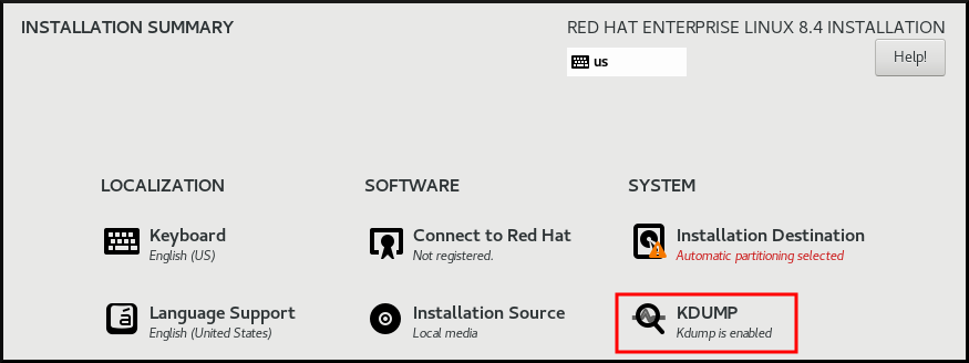
- In Kdump Memory Reservation, select Manual` if you must customize the memory reserve.
In KDUMP > Memory To Be Reserved (MB), set the required memory reserve for
kdump.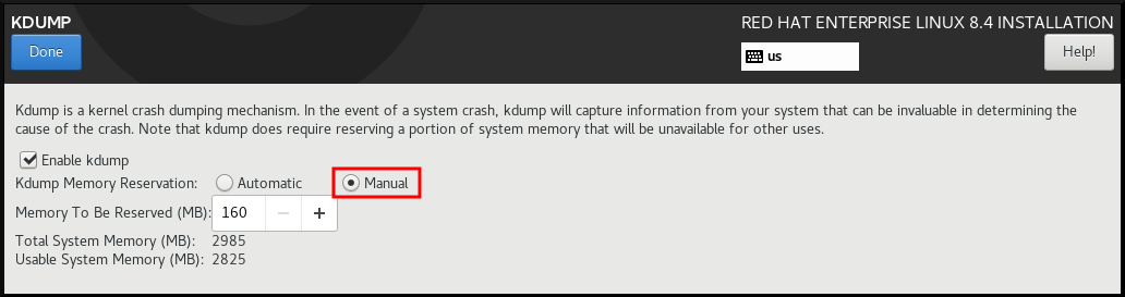
41.1.3. Installing kdump on the command line
Installation options such as custom Kickstart installations, in some cases does not install or enable kdump by default. The following procedure helps you enable kdump in this case.
Prerequisites
- An active RHEL subscription.
-
A repository containing the
kexec-toolspackage for your system CPU architecture. -
Fulfilled requirements for
kdumpconfigurations and targets. For details, see Supported kdump configurations and targets.
Procedure
Check if
kdumpis installed on your system:# rpm -q kexec-toolsOutput if the package is installed:
kexec-tools-2.0.17-11.el8.x86_64Output if the package is not installed:
package kexec-tools is not installedInstall
kdumpand other necessary packages:# dnf install kexec-tools
From kernel-3.10.0-693.el7 onwards, the Intel IOMMU driver is supported for kdump. For kernel-3.10.0-514[.XYZ].el7 and early versions, you must ensure that Intel IOMMU is disabled to prevent an unresponsive capture kernel.
41.2. Configuring kdump on the command line
The memory for kdump is reserved during the system boot. You can configure the memory size in the system’s Grand Unified Bootloader (GRUB) configuration file. The memory size depends on the crashkernel= value specified in the configuration file and the size of the physical memory of system.
41.2.1. Estimating the kdump size
When planning and building your kdump environment, it is important to know the space required by the crash dump file.
The makedumpfile --mem-usage command estimates the space required by the crash dump file. It generates a memory usage report. The report helps you decide the dump level and the pages that are safe to exclude.
Procedure
Enter the following command to generate a memory usage report:
# makedumpfile --mem-usage /proc/kcore TYPE PAGES EXCLUDABLE DESCRIPTION ------------------------------------------------------------- ZERO 501635 yes Pages filled with zero CACHE 51657 yes Cache pages CACHE_PRIVATE 5442 yes Cache pages + private USER 16301 yes User process pages FREE 77738211 yes Free pages KERN_DATA 1333192 no Dumpable kernel data
The makedumpfile --mem-usage command reports required memory in pages. This means that you must calculate the size of memory in use against the kernel page size.
41.2.2. Configuring kdump memory usage
The memory reservation for kdump occurs during the system boot. The memory size is set in the system’s Grand Unified Bootloader (GRUB) configuration. The memory size depends on the value of the crashkernel= option specified in the configuration file and the size of the system physical memory.
You can define the crashkernel= option in many ways. You can specify the crashkernel= value or configure the auto option. The crashkernel=auto parameter reserves memory automatically, based on the total amount of physical memory in the system. When configured, the kernel automatically reserves an appropriate amount of required memory for the capture kernel. This helps to prevent Out-of-Memory (OOM) errors.
The automatic memory allocation for kdump varies based on system hardware architecture and available memory size.
If the system has less than the minimum memory threshold for automatic allocation, you can configure the amount of reserved memory manually.
Prerequisites
- You have root permissions on the system.
-
Fulfilled requirements for
kdumpconfigurations and targets. For details, see Supported kdump configurations and targets.
Procedure
Prepare the
crashkernel=option.For example, to reserve 128 MB of memory, use the following:
crashkernel=128MAlternatively, you can set the amount of reserved memory to a variable depending on the total amount of installed memory. The syntax for memory reservation into a variable is
crashkernel=<range1>:<size1>,<range2>:<size2>. For example:crashkernel=512M-2G:64M,2G-:128MThe command reserves 64 MB of memory if the total amount of system memory is in the range of 512 MB and 2 GB. If the total amount of memory is more than 2 GB, the memory reserve is 128 MB.
Offset the reserved memory.
Some systems require to reserve memory with a certain fixed offset because the
crashkernelreservation happens early, and you may need to reserve more memory for special usage. When you define an offset, the reserved memory begins there. To offset the reserved memory, use the following syntax:crashkernel=128M@16MIn this example,
kdumpreserves 128 MB of memory starting at 16 MB (physical address0x01000000). If you set the offset parameter to 0 or omit entirely,kdumpoffsets the reserved memory automatically. You can also use this syntax when setting a variable memory reservation. In that case, the offset is always specified last. For example:crashkernel=512M-2G:64M,2G-:128M@16M
Apply the
crashkernel=option to your boot loader configuration:# grubby --update-kernel=ALL --args="crashkernel=<value>"Replace
<value>with the value of thecrashkernel=option that you prepared in the previous step.
41.2.3. Configuring the kdump target
The crash dump is usually stored as a file in a local file system, written directly to a device. Optionally, you can send crash dump over a network by using the NFS or SSH protocols. Only one of these options to preserve a crash dump file can be set at a time. The default behavior is to store it in the /var/crash/ directory of the local file system.
Prerequisites
- You have root permissions on the system.
-
Fulfilled requirements for
kdumpconfigurations and targets. For details, see Supported kdump configurations and targets.
Procedure
To store the crash dump file in
/var/crash/directory of the local file system, edit the/etc/kdump.conffile and specify the path:path /var/crashThe option
path /var/crashrepresents the path to the file system in whichkdumpsaves the crash dump file.Note-
When you specify a dump target in the
/etc/kdump.conffile, then the path is relative to the specified dump target. -
When you do not specify a dump target in the
/etc/kdump.conffile, then the path represents the absolute path from the root directory.
Depending on the file system mounted in the current system, the dump target and the adjusted dump path are configured automatically.
-
When you specify a dump target in the
To secure the crash dump file and the accompanying files produced by
kdump, you should set up proper attributes for the target destination directory, such as user permissions and SELinux contexts. Additionally, you can define a script, for examplekdump_post.shin thekdump.conffile as follows:kdump_post <path_to_kdump_post.sh>The
kdump_postdirective specifies a shell script or a command that executes afterkdumphas completed capturing and saving a crash dump to the specified destination. You can use this mechanism to extend the functionality ofkdumpto perform actions including the adjustments in file permissions.-
The
kdumptarget configuration
# *grep -v ^# /etc/kdump.conf | grep -v ^$*
ext4 /dev/mapper/vg00-varcrashvol
path /var/crash
core_collector makedumpfile -c --message-level 1 -d 31
The dump target is specified (ext4 /dev/mapper/vg00-varcrashvol), and, therefore, it is mounted at /var/crash. The path option is also set to /var/crash. Therefore, the kdump saves the vmcore file in the /var/crash/var/crash directory.
To change the local directory for saving the crash dump, edit the
/etc/kdump.confconfiguration file as arootuser:-
Remove the hash sign (
#) from the beginning of the#path /var/crashline. Replace the value with the intended directory path. For example:
path /usr/local/coresImportantIn RHEL 8, the directory defined as the
kdumptarget using thepathdirective must exist when thekdumpsystemdservice starts to avoid failures. Unlike in earlier versions of RHEL, the directory is no longer created automatically if it does not exist when the service starts.
-
Remove the hash sign (
To write the file to a different partition, edit the
/etc/kdump.confconfiguration file:Remove the hash sign (
#) from the beginning of the#ext4line, depending on your choice.-
device name (the
#ext4 /dev/vg/lv_kdumpline) -
file system label (the
#ext4 LABEL=/bootline) -
UUID (the
#ext4 UUID=03138356-5e61-4ab3-b58e-27507ac41937line)
-
device name (the
Change the file system type and the device name, label or UUID, to the required values. The correct syntax for specifying UUID values is both
UUID="correct-uuid"andUUID=correct-uuid. For example:ext4 UUID=03138356-5e61-4ab3-b58e-27507ac41937ImportantIt is recommended to specify storage devices by using a
LABEL=orUUID=. Disk device names such as/dev/sda3are not guaranteed to be consistent across reboot.When you use Direct Access Storage Device (DASD) on IBM Z hardware, ensure the dump devices are correctly specified in
/etc/dasd.confbefore proceeding withkdump.
To write the crash dump directly to a device, edit the
/etc/kdump.confconfiguration file:-
Remove the hash sign (
#) from the beginning of the#raw /dev/vg/lv_kdumpline. Replace the value with the intended device name. For example:
raw /dev/sdb1
-
Remove the hash sign (
To store the crash dump to a remote machine by using the
NFSprotocol:-
Remove the hash sign (
#) from the beginning of the#nfs my.server.com:/export/tmpline. Replace the value with a valid hostname and directory path. For example:
nfs penguin.example.com:/export/coresRestart the
kdumpservice for the changes to take effect:sudo systemctl restart kdump.serviceNoteWhile using the NFS directive to specify the NFS target,
kdump.serviceautomatically attempts to mount the NFS target to check the disk space. There is no need to mount the NFS target in advance. To preventkdump.servicefrom mounting the target, use thedracut_args --mountdirective inkdump.conf. This will enablekdump.serviceto call thedracututility with the--mountargument to specify the NFS target.
-
Remove the hash sign (
To store the crash dump to a remote machine by using the SSH protocol:
-
Remove the hash sign (
#) from the beginning of the#ssh user@my.server.comline. - Replace the value with a valid username and hostname.
Include your SSH key in the configuration.
-
Remove the hash sign from the beginning of the
#sshkey /root/.ssh/kdump_id_rsaline. Change the value to the location of a key valid on the server you are trying to dump to. For example:
ssh john@penguin.example.com sshkey /root/.ssh/mykey
-
Remove the hash sign from the beginning of the
-
Remove the hash sign (
41.2.4. Configuring the kdump core collector
The kdump service uses a core_collector program to capture the crash dump image. In RHEL, the makedumpfile utility is the default core collector. It helps shrink the dump file by:
- Compressing the size of a crash dump file and copying only necessary pages by using various dump levels.
- Excluding unnecessary crash dump pages.
- Filtering the page types to be included in the crash dump.
Crash dump file compression is enabled by default in the RHEL 7 and above.
If you need to customize the crash dump file compression, follow this procedure.
Syntax
core_collector makedumpfile -l --message-level 1 -d 31Options
-
-c,-lor-p: specify compress dump file format by each page using either,zlibfor-coption,lzofor-loption orsnappyfor-poption. -
-d(dump_level): excludes pages so that they are not copied to the dump file. -
--message-level: specify the message types. You can restrict outputs printed by specifyingmessage_levelwith this option. For example, specifying 7 asmessage_levelprints common messages and error messages. The maximum value ofmessage_levelis 31.
Prerequisites
- You have root permissions on the system.
-
Fulfilled requirements for
kdumpconfigurations and targets. For details, see Supported kdump configurations and targets.
Procedure
-
As a
root, edit the/etc/kdump.confconfiguration file and remove the hash sign ("#") from the beginning of the#core_collector makedumpfile -l --message-level 1 -d 31. - Enter the following command to enable crash dump file compression:
core_collector makedumpfile -l --message-level 1 -d 31
The -l option specifies the dump compressed file format. The -d option specifies dump level as 31. The --message-level option specifies message level as 1.
Also, consider following examples with the -c and -p options:
To compress a crash dump file by using
-c:core_collector makedumpfile -c -d 31 --message-level 1To compress a crash dump file by using
-p:core_collector makedumpfile -p -d 31 --message-level 1
41.2.5. Configuring the kdump default failure responses
By default, when kdump fails to create a crash dump file at the configured target location, the system reboots and the dump is lost in the process. You can change the default failure response and configure kdump to perform a different operation when it fails to save the core dump to the primary target. The additional actions are:
dump_to_rootfs-
Saves the core dump to the
rootfile system. reboot- Reboots the system, losing the core dump in the process.
halt- Stops the system, losing the core dump in the process.
poweroff- Power the system off, losing the core dump in the process.
shell-
Runs a shell session from within the
initramfs, you can record the core dump manually. final_action-
Enables additional operations such as
reboot,halt, andpoweroffafter a successfulkdumpor when shell ordump_to_rootfsfailure action completes. The default isreboot. failure_action-
Specifies the action to perform when a dump might fail in a kernel crash. The default is
reboot.
Prerequisites
- Root permissions.
-
Fulfilled requirements for
kdumpconfigurations and targets. For details, see Supported kdump configurations and targets.
Procedure
-
As a
rootuser, remove the hash sign (#) from the beginning of the#failure_actionline in the/etc/kdump.confconfiguration file. Replace the value with a required action.
failure_action poweroff
41.2.6. Configuration file for kdump
The configuration file for kdump kernel is /etc/sysconfig/kdump. This file controls the kdump kernel command line parameters. For most configurations, use the default options. However, in some scenarios you might need to modify certain parameters to control the kdump kernel behavior. For example, modifying the KDUMP_COMMANDLINE_APPEND option to append the kdump kernel command-line to obtain a detailed debugging output or the KDUMP_COMMANDLINE_REMOVE option to remove arguments from the kdump command line.
KDUMP_COMMANDLINE_REMOVEThis option removes arguments from the current
kdumpcommand line. It removes parameters that can causekdumperrors orkdumpkernel boot failures. These parameters might have been parsed from the previousKDUMP_COMMANDLINEprocess or inherited from the/proc/cmdlinefile.When this variable is not configured, it inherits all values from the
/proc/cmdlinefile. Configuring this option also provides information that is helpful in debugging an issue.To remove certain arguments, add them to
KDUMP_COMMANDLINE_REMOVEas follows:
# KDUMP_COMMANDLINE_REMOVE="hugepages hugepagesz slub_debug quiet log_buf_len swiotlb"KDUMP_COMMANDLINE_APPENDThis option appends arguments to the current command line. These arguments might have been parsed by the previous
KDUMP_COMMANDLINE_REMOVEvariable.For the
kdumpkernel, disabling certain modules such asmce,cgroup,numa,hest_disablecan help prevent kernel errors. These modules can consume a significant part of the kernel memory reserved forkdumpor causekdumpkernel boot failures.To disable memory
cgroupson thekdumpkernel command line, run the command as follows:
KDUMP_COMMANDLINE_APPEND="cgroup_disable=memory"41.2.7. Testing the kdump configuration
After configuring kdump, you must manually test a system crash and ensure that the vmcore file is generated in the defined kdump target. The vmcore file is captured from the context of the freshly booted kernel. Therefore, vmcore has critical information for debugging a kernel crash.
Do not test kdump on active production systems. The commands to test kdump will cause the kernel to crash with loss of data. Depending on your system architecture, ensure that you schedule significant maintenance time because kdump testing might require several reboots with a long boot time.
If the vmcore file is not generated during the kdump test, identify and fix issues before you run the test again for a successful kdump testing.
If you make any manual system modifications, you must test the kdump configuration at the end of any system modification. For example, if you make any of the following changes, ensure that you test the kdump configuration for an optimal kdump performances for:
- Package upgrades.
- Hardware level changes, for example, storage or networking changes.
- Firmware upgrades.
- New installation and application upgrades that include third party modules.
- If you use the hot-plugging mechanism to add more memory on hardware that support this mechanism.
-
After you make changes in the
/etc/kdump.confor/etc/sysconfig/kdumpfile.
Prerequisites
- You have root permissions on the system.
-
You have saved all important data. The commands to test
kdumpcause the kernel to crash with loss of data. - You have scheduled significant machine maintenance time depending on the system architecture.
Procedure
Enable the
kdumpservice:# kdumpctl restartCheck the status of the
kdumpservice with thekdumpctl:# kdumpctl status kdump:Kdump is operationalOptionally, if you use the
systemctlcommand, the output prints in thesystemdjournal.Start a kernel crash to test the
kdumpconfiguration. Thesysrq-triggerkey combination causes the kernel to crash and might reboot the system if required.# echo c > /proc/sysrq-triggerOn a kernel reboot, the
address-YYYY-MM-DD-HH:MM:SS/vmcorefile is created at the location you have specified in the/etc/kdump.conffile. The default is/var/crash/.
41.2.8. Files produced by kdump after system crash
After your system crashes, the kdump service captures the kernel memory in a dump file (vmcore) and it also generates additional diagnostic files to aid in troubleshooting and postmortem analysis.
Files produced by kdump:
-
vmcore- main kernel memory dump file containing system memory at the time of the crash. It includes data as per the configuration of thecore_collectorprogram specified inkdumpconfiguration. By default the kernel data structures, process information, stack traces, and other diagnostic information. -
vmcore-dmesg.txt- contents of the kernel ring buffer log (dmesg) from the primary kernel that panicked. -
kexec-dmesg.log- has kernel and system log messages from the execution of the secondarykexeckernel that collects thevmcoredata.
41.2.9. Enabling and disabling the kdump service
You can configure to enable or disable the kdump functionality on a specific kernel or on all installed kernels. You must routinely test the kdump functionality and validate its operates correctly.
Prerequisites
- You have root permissions on the system.
-
You have completed
kdumprequirements for configurations and targets. See Supported kdump configurations and targets. -
All configurations for installing
kdumpare set up as required.
Procedure
Enable the
kdumpservice formulti-user.target:# systemctl enable kdump.serviceStart the service in the current session:
# systemctl start kdump.serviceStop the
kdumpservice:# systemctl stop kdump.serviceDisable the
kdumpservice:# systemctl disable kdump.service
It is recommended to set kptr_restrict=1 as default. When kptr_restrict is set to (1) as default, the kdumpctl service loads the crash kernel regardless of whether the Kernel Address Space Layout (KASLR) is enabled.
If kptr_restrict is not set to 1 and KASLR is enabled, the contents of /proc/kore file are generated as all zeros. The kdumpctl service fails to access the /proc/kcore file and load the crash kernel. The kexec-kdump-howto.txt file displays a warning message, which recommends you to set kptr_restrict=1. Verify for the following in the sysctl.conf file to ensure that kdumpctl service loads the crash kernel:
-
Kernel
kptr_restrict=1in thesysctl.conffile.
41.2.10. Preventing kernel drivers from loading for kdump
You can control the capture kernel from loading certain kernel drivers by adding the KDUMP_COMMANDLINE_APPEND= variable in the /etc/sysconfig/kdump configuration file. By using this method, you can prevent the kdump initial RAM disk image initramfs from loading the specified kernel module. This helps to prevent the out-of-memory (OOM) killer errors or other crash kernel failures.
You can append the KDUMP_COMMANDLINE_APPEND= variable by using one of the following configuration options:
-
rd.driver.blacklist=<modules> -
modprobe.blacklist=<modules>
Prerequisites
- You have root permissions on the system.
Procedure
Display the list of modules that are loaded to the currently running kernel. Select the kernel module that you intend to block from loading:
$ lsmod Module Size Used by fuse 126976 3 xt_CHECKSUM 16384 1 ipt_MASQUERADE 16384 1 uinput 20480 1 xt_conntrack 16384 1Update the
KDUMP_COMMANDLINE_APPEND=variable in the/etc/sysconfig/kdumpfile. For example:KDUMP_COMMANDLINE_APPEND="rd.driver.blacklist=hv_vmbus,hv_storvsc,hv_utils,hv_netvsc,hid-hyperv"Also, consider the following example by using the
modprobe.blacklist=<modules>configuration option:KDUMP_COMMANDLINE_APPEND="modprobe.blacklist=emcp modprobe.blacklist=bnx2fc modprobe.blacklist=libfcoe modprobe.blacklist=fcoe"Restart the
kdumpservice:# systemctl restart kdump
41.2.11. Running kdump on systems with encrypted disk
When you run a LUKS encrypted partition, systems require certain amount of available memory. If the system has less than the required amount of available memory, the cryptsetup utility fails to mount the partition. As a result, capturing the vmcore file to an encrypted target location fails in the second kernel (capture kernel).
The kdumpctl estimate command helps you estimate the amount of memory you need for kdump. kdumpctl estimate prints the recommended crashkernel value, which is the most suitable memory size required for kdump.
The recommended crashkernel value is calculated based on the current kernel size, kernel module, initramfs, and the LUKS encrypted target memory requirement.
If you are using the custom crashkernel= option, kdumpctl estimate prints the LUKS required size value. The value is the memory size required for LUKS encrypted target.
Procedure
Print the estimate
crashkernel=value:# *kdumpctl estimate* Encrypted kdump target requires extra memory, assuming using the keyslot with minimum memory requirement Reserved crashkernel: 256M Recommended crashkernel: 652M Kernel image size: 47M Kernel modules size: 8M Initramfs size: 20M Runtime reservation: 64M LUKS required size: 512M Large modules: <none> WARNING: Current crashkernel size is lower than recommended size 652M.-
Configure the amount of required memory by increasing the
crashkernel=value. - Reboot the system.
If the kdump service still fails to save the dump file to the encrypted target, increase the crashkernel= value as required.
41.3. Enabling kdump
For your RHEL 8 systems, you can configure enabling or disabling the kdump functionality on a specific kernel or on all installed kernels. However, you must routinely test the kdump functionality and validate its working status.
41.3.1. Enabling kdump for all installed kernels
The kdump service starts by enabling kdump.service after the kexec tool is installed. You can enable and start the kdump service for all kernels installed on the machine.
Prerequisites
- You have administrator privileges.
Procedure
Add the
crashkernel=command-line parameter to all installed kernels:# grubby --update-kernel=ALL --args="crashkernel=xxM"xxMis the required memory in megabytes.Reboot the system:
# rebootEnable the
kdumpservice:# systemctl enable --now kdump.service
Verification
Check that the
kdumpservice is running:# systemctl status kdump.service ○ kdump.service - Crash recovery kernel arming Loaded: loaded (/usr/lib/systemd/system/kdump.service; enabled; vendor preset: disabled) Active: active (live)
41.3.2. Enabling kdump for a specific installed kernel
You can enable the kdump service for a specific kernel on the machine.
Prerequisites
- You have administrator privileges.
Procedure
List the kernels installed on the machine.
# ls -a /boot/vmlinuz-* /boot/vmlinuz-0-rescue-2930657cd0dc43c2b75db480e5e5b4a9 /boot/vmlinuz-4.18.0-330.el8.x86_64 /boot/vmlinuz-4.18.0-330.rt7.111.el8.x86_64Add a specific
kdumpkernel to the system’s Grand Unified Bootloader (GRUB) configuration.For example:
# grubby --update-kernel=vmlinuz-4.18.0-330.el8.x86_64 --args="crashkernel=xxM"xxMis the required memory reserve in megabytes.Enable the
kdumpservice.# systemctl enable --now kdump.service
Verification
Check that the
kdumpservice is running.# systemctl status kdump.service ○ kdump.service - Crash recovery kernel arming Loaded: loaded (/usr/lib/systemd/system/kdump.service; enabled; vendor preset: disabled) Active: active (live)
41.3.3. Disabling the kdump service
You can stop the kdump.service and disable the service from starting on your RHEL 8 systems.
Prerequisites
-
Fulfilled requirements for
kdumpconfigurations and targets. For details, see Supported kdump configurations and targets. -
All configurations for installing
kdumpare set up according to your needs. For details, see Installing kdump.
Procedure
To stop the
kdumpservice in the current session:# systemctl stop kdump.serviceTo disable the
kdumpservice:# systemctl disable kdump.service
It is recommended to set kptr_restrict=1 as default. When kptr_restrict is set to (1) as default, the kdumpctl service loads the crash kernel regardless of whether the Kernel Address Space Layout (KASLR) is enabled.
If kptr_restrict is not set to 1 and KASLR is enabled, the contents of /proc/kore file are generated as all zeros. The kdumpctl service fails to access the /proc/kcore file and load the crash kernel. The kexec-kdump-howto.txt file displays a warning message, which recommends you to set kptr_restrict=1. Verify for the following in the sysctl.conf file to ensure that kdumpctl service loads the crash kernel:
-
Kernel
kptr_restrict=1in thesysctl.conffile.
41.4. Configuring kdump in the web console
You can set up and test the kdump configuration by using the RHEL 8 web console. The web console can enable the kdump service at boot time. With the web console, you can configure the reserved memory for kdump and to select the vmcore saving location in an uncompressed or compressed format.
41.4.1. Configuring kdump memory usage and target location in web console
You can configure the memory reserve for the kdump kernel and also specify the target location to capture the vmcore dump file with the RHEL web console interface.
Prerequisites
- The web console must be installed and accessible. For details, see Installing the web console.
Procedure
-
In the web console, open the tab and start the
kdumpservice by setting the Kernel crash dump switch to on. Configure the
kdumpmemory usage in the terminal, for example:$ sudo grubby --update-kernel ALL --args crashkernel=512MRestart the system to apply the changes.
- In the Kernel dump tab, click Edit at the end of the Crash dump location field.
Specify the target directory for saving the
vmcoredump file:- For a local filesystem, select Local Filesystem from the drop-down menu.
For a remote system by using the SSH protocol, select Remote over SSH from the drop-down menu and specify the following fields:
- In the Server field, enter the remote server address.
- In the SSH key field, enter the SSH key location.
- In the Directory field, enter the target directory.
For a remote system by using the NFS protocol, select Remote over NFS from the drop-down menu and specify the following fields:
- In the Server field, enter the remote server address.
- In the Export field, enter the location of the shared folder of an NFS server.
In the Directory field, enter the target directory.
NoteYou can reduce the size of the
vmcorefile by selecting the Compression checkbox.
Optional: Display the automation script by clicking View automation script.
A window with the generated script opens. You can browse a shell script and an Ansible playbook generation options tab.
Optional: Copy the script by clicking Copy to clipboard.
You can use this script to apply the same configuration on multiple machines.
Verification
- Click .
Click Crash system under Test kdump settings.
WarningWhen you start the system crash, the kernel operation stops and results in a system crash with data loss.
41.5. Supported kdump configurations and targets
The kdump mechanism is a feature of the Linux kernel that generates a crash dump file when a kernel crash occurs. The kernel dump file has critical information that helps to analyze and determine the root cause of a kernel crash. The crash can be because of various factors, hardware issues or third-party kernel modules problems, to name a few.
By using the provided information and procedures, you can perform the following actions:
- Identify the supported configurations and targets for your RHEL 8 systems.
- Configure kdump.
- Verify kdump operation.
41.5.1. Memory requirements for kdump
For kdump to capture a kernel crash dump and save it for further analysis, a part of the system memory should be permanently reserved for the capture kernel. When reserved, this part of the system memory is not available to the main kernel.
The memory requirements vary based on certain system parameters. One of the major factors is the system’s hardware architecture. To identify the exact machine architecture, such as Intel 64 and AMD64, also known as x86_64, and print it to standard output, use the following command:
$ uname -m
With the stated list of minimum memory requirements, you can set the appropriate memory size to automatically reserve a memory for kdump on the latest available versions. The memory size depends on the system’s architecture and total available physical memory.
| Architecture | Available Memory | Minimum Reserved Memory |
|---|---|---|
|
AMD64 and Intel 64 ( | 1 GB to 4 GB | 192 MB of RAM |
| 4 GB to 64 GB | 256 MB of RAM | |
| 64 GB and more | 512 MB of RAM | |
|
64-bit ARM architecture ( | 2 GB and more | 480 MB of RAM |
|
IBM Power Systems ( | 2 GB to 4 GB | 384 MB of RAM |
| 4 GB to 16 GB | 512 MB of RAM | |
| 16 GB to 64 GB | 1 GB of RAM | |
| 64 GB to 128 GB | 2 GB of RAM | |
| 128 GB and more | 4 GB of RAM | |
|
IBM Z ( | 1 GB to 4 GB | 192 MB of RAM |
| 4 GB to 64 GB | 256 MB of RAM | |
| 64 GB and more | 512 MB of RAM |
On many systems, kdump is able to estimate the amount of required memory and reserve it automatically. This behavior is enabled by default, but only works on systems that have more than a certain amount of total available memory, which varies based on the system architecture.
The automatic configuration of reserved memory based on the total amount of memory in the system is a best effort estimation. The actual required memory might vary due to other factors such as I/O devices. Using not enough of memory might cause debug kernel unable to boot as a capture kernel in the case of kernel panic. To avoid this problem, increase the crash kernel memory sufficiently.
41.5.2. Minimum threshold for automatic memory reservation
By default, the kexec-tools utility configures the crashkernel command line parameter and reserves a certain amount of memory for kdump. On some systems however, it is still possible to assign memory for kdump either by using the crashkernel=auto parameter in the boot loader configuration file, or by enabling this option in the graphical configuration utility. For this automatic reservation to work, a certain amount of total memory needs to be available in the system. The memory requirement varies based on the system’s architecture. If the system memory is less than the specified threshold value, you must configure the memory manually.
| Architecture | Required Memory |
|---|---|
|
AMD64 and Intel 64 ( | 2 GB |
|
IBM Power Systems ( | 2 GB |
|
IBM Z ( | 4 GB |
The crashkernel=auto option in the boot command line is no longer supported on RHEL 9 and later releases.
41.5.3. Supported kdump targets
When a kernel crash occurs, the operating system saves the dump file on the configured or default target location. You can save the dump file either directly to a device, store as a file on a local file system, or send the dump file over a network. With the following list of dump targets, you can know the targets that are currently supported or not supported by kdump.
| Target type | Supported Targets | Unsupported Targets |
|---|---|---|
| Physical storage |
|
|
| Network |
|
|
| Hypervisor |
| |
| File systems | The ext[234], XFS, and NFS file systems. |
The |
| Firmware |
|
41.5.4. Supported kdump filtering levels
To reduce the size of the dump file, kdump uses the makedumpfile core collector to compress the data and also exclude unwanted information, for example, you can remove hugepages and hugetlbfs pages by using the -8 level. The levels that makedumpfile currently supports can be seen in the table for Filtering levels for `kdump` .
| Option | Description |
|---|---|
|
| Zero pages |
|
| Cache pages |
|
| Cache private |
|
| User pages |
|
| Free pages |
41.5.5. Supported default failure responses
By default, when kdump fails to create a core dump, the operating system reboots. However, you can configure kdump to perform a different operation in case it fails to save the core dump to the primary target.
| Option | Description |
|---|---|
|
| Attempt to save the core dump to the root file system. This option is especially useful in combination with a network target: if the network target is unreachable, this option configures kdump to save the core dump locally. The system is rebooted afterwards. |
|
| Reboot the system, losing the core dump in the process. |
|
| Halt the system, losing the core dump in the process. |
|
| Power off the system, losing the core dump in the process. |
|
| Run a shell session from within the initramfs, allowing the user to record the core dump manually. |
|
|
Enable additional operations such as |
41.5.6. Using final_action parameter
When kdump succeeds or if kdump fails to save the vmcore file at the configured target, you can perform additional operations like reboot, halt, and poweroff by using the final_action parameter. If the final_action parameter is not specified, reboot is the default response.
Procedure
To configure
final_action, edit the/etc/kdump.conffile and add one of the following options:-
final_action reboot -
final_action halt -
final_action poweroff
-
Restart the
kdumpservice for the changes to take effect.# kdumpctl restart
41.5.7. Using failure_action parameter
The failure_action parameter specifies the action to perform when a dump fails in the event of a kernel crash. The default action for failure_action is reboot that reboots the system.
The parameter recognizes the following actions to take:
reboot- Reboots the system after a dump failure.
dump_to_rootfs- Saves the dump file on a root file system when a non-root dump target is configured.
halt- Halts the system.
poweroff- Stops the running operations on the system.
shell-
Starts a shell session inside
initramfs, from which you can manually perform additional recovery actions.
Procedure
To configure an action to take if the dump fails, edit the
/etc/kdump.conffile and specify one of thefailure_actionoptions:-
failure_action reboot -
failure_action halt -
failure_action poweroff -
failure_action shell -
failure_action dump_to_rootfs
-
Restart the
kdumpservice for the changes to take effect.# kdumpctl restart
41.6. Testing the kdump configuration
After configuring kdump, you must manually test a system crash and ensure that the vmcore file is generated in the defined kdump target. The vmcore file is captured from the context of the freshly booted kernel. Therefore, vmcore has critical information for debugging a kernel crash.
Do not test kdump on active production systems. The commands to test kdump will cause the kernel to crash with loss of data. Depending on your system architecture, ensure that you schedule significant maintenance time because kdump testing might require several reboots with a long boot time.
If the vmcore file is not generated during the kdump test, identify and fix issues before you run the test again for a successful kdump testing.
If you make any manual system modifications, you must test the kdump configuration at the end of any system modification. For example, if you make any of the following changes, ensure that you test the kdump configuration for an optimal kdump performances for:
- Package upgrades.
- Hardware level changes, for example, storage or networking changes.
- Firmware upgrades.
- New installation and application upgrades that include third party modules.
- If you use the hot-plugging mechanism to add more memory on hardware that support this mechanism.
-
After you make changes in the
/etc/kdump.confor/etc/sysconfig/kdumpfile.
Prerequisites
- You have root permissions on the system.
-
You have saved all important data. The commands to test
kdumpcause the kernel to crash with loss of data. - You have scheduled significant machine maintenance time depending on the system architecture.
Procedure
Enable the
kdumpservice:# kdumpctl restartCheck the status of the
kdumpservice with thekdumpctl:# kdumpctl status kdump:Kdump is operationalOptionally, if you use the
systemctlcommand, the output prints in thesystemdjournal.Start a kernel crash to test the
kdumpconfiguration. Thesysrq-triggerkey combination causes the kernel to crash and might reboot the system if required.# echo c > /proc/sysrq-triggerOn a kernel reboot, the
address-YYYY-MM-DD-HH:MM:SS/vmcorefile is created at the location you have specified in the/etc/kdump.conffile. The default is/var/crash/.
41.7. Using kexec to boot into a different kernel
You can use the kexec system call to enable loading and booting into another kernel from the currently running kernel. kexec performs a function of a boot loader from within the kernel.
The kexec utility loads the kernel and the initramfs image for the kexec system call to boot into another kernel.
The following procedure describes how to manually invoke the kexec system call when using the kexec utility to reboot into another kernel.
Procedure
Run the
kexecutility:# kexec -l /boot/vmlinuz-3.10.0-1040.el7.x86_64 --initrd=/boot/initramfs-3.10.0-1040.el7.x86_64.img --reuse-cmdlineThe command manually loads the kernel and the
initramfsimage for thekexecsystem call.Reboot the system:
# rebootThe command detects the kernel, shuts down all services and then calls the
kexecsystem call to reboot into the kernel you provided in the previous step.
When you use the kexec -e command to reboot your machine into a different kernel, the system does not go through the standard shutdown sequence before starting the next kernel. This can cause data loss or an unresponsive system.
41.8. Preventing kernel drivers from loading for kdump
You can control the capture kernel from loading certain kernel drivers by adding the KDUMP_COMMANDLINE_APPEND= variable in the /etc/sysconfig/kdump configuration file. By using this method, you can prevent the kdump initial RAM disk image initramfs from loading the specified kernel module. This helps to prevent the out-of-memory (OOM) killer errors or other crash kernel failures.
You can append the KDUMP_COMMANDLINE_APPEND= variable by using one of the following configuration options:
-
rd.driver.blacklist=<modules> -
modprobe.blacklist=<modules>
Prerequisites
- You have root permissions on the system.
Procedure
Display the list of modules that are loaded to the currently running kernel. Select the kernel module that you intend to block from loading:
$ lsmod Module Size Used by fuse 126976 3 xt_CHECKSUM 16384 1 ipt_MASQUERADE 16384 1 uinput 20480 1 xt_conntrack 16384 1Update the
KDUMP_COMMANDLINE_APPEND=variable in the/etc/sysconfig/kdumpfile. For example:KDUMP_COMMANDLINE_APPEND="rd.driver.blacklist=hv_vmbus,hv_storvsc,hv_utils,hv_netvsc,hid-hyperv"Also, consider the following example by using the
modprobe.blacklist=<modules>configuration option:KDUMP_COMMANDLINE_APPEND="modprobe.blacklist=emcp modprobe.blacklist=bnx2fc modprobe.blacklist=libfcoe modprobe.blacklist=fcoe"Restart the
kdumpservice:# systemctl restart kdump
41.9. Running kdump on systems with encrypted disk
When you run a LUKS encrypted partition, systems require certain amount of available memory. If the system has less than the required amount of available memory, the cryptsetup utility fails to mount the partition. As a result, capturing the vmcore file to an encrypted target location fails in the second kernel (capture kernel).
The kdumpctl estimate command helps you estimate the amount of memory you need for kdump. kdumpctl estimate prints the recommended crashkernel value, which is the most suitable memory size required for kdump.
The recommended crashkernel value is calculated based on the current kernel size, kernel module, initramfs, and the LUKS encrypted target memory requirement.
If you are using the custom crashkernel= option, kdumpctl estimate prints the LUKS required size value. The value is the memory size required for LUKS encrypted target.
Procedure
Print the estimate
crashkernel=value:# *kdumpctl estimate* Encrypted kdump target requires extra memory, assuming using the keyslot with minimum memory requirement Reserved crashkernel: 256M Recommended crashkernel: 652M Kernel image size: 47M Kernel modules size: 8M Initramfs size: 20M Runtime reservation: 64M LUKS required size: 512M Large modules: <none> WARNING: Current crashkernel size is lower than recommended size 652M.-
Configure the amount of required memory by increasing the
crashkernel=value. - Reboot the system.
If the kdump service still fails to save the dump file to the encrypted target, increase the crashkernel= value as required.
41.10. Firmware assisted dump mechanisms
Firmware assisted dump (fadump) is a dump capturing mechanism, provided as an alternative to the kdump mechanism on IBM POWER systems. The kexec and kdump mechanisms are useful for capturing core dumps on AMD64 and Intel 64 systems. However, some hardware, such as mini systems and mainframe computers, uses the onboard firmware to isolate regions of memory and prevent any accidental overwriting of data that is important to the crash analysis. The fadump utility is optimized for the fadump mechanisms and their integration with RHEL on IBM POWER systems.
41.10.1. Firmware assisted dump on IBM PowerPC hardware
The fadump utility captures the vmcore file from a fully-reset system with PCI and I/O devices. This mechanism uses firmware to preserve memory regions during a crash and then reuses the kdump userspace scripts to save the vmcore file. The memory regions consist of all system memory contents, except the boot memory, system registers, and hardware Page Table Entries (PTEs).
The fadump mechanism offers improved reliability over the traditional dump type, by rebooting the partition and using a new kernel to dump the data from the previous kernel crash. The fadump requires an IBM POWER6 processor-based or later version hardware platform.
For further details about the fadump mechanism, including PowerPC specific methods of resetting hardware, see the /usr/share/doc/kexec-tools/fadump-howto.txt file.
The area of memory that is not preserved, known as boot memory, is the amount of RAM required to successfully boot the kernel after a crash event. By default, the boot memory size is 256MB or 5% of total system RAM, whichever is larger.
Unlike kexec-initiated event, the fadump mechanism uses the production kernel to recover a crash dump. When booting after a crash, PowerPC hardware makes the device node /proc/device-tree/rtas/ibm.kernel-dump available to the proc filesystem (procfs). The fadump-aware kdump scripts, check for the stored vmcore, and then complete the system reboot cleanly.
41.10.2. Enabling firmware assisted dump mechanism
You can enhance the crash dumping capabilities of IBM POWER systems by enabling the firmware assisted dump (fadump) mechanism.
In the Secure Boot environment, the GRUB boot loader allocates a boot memory region, known as the Real Mode Area (RMA). The RMA has a size of 512 MB, divided among the boot components. If a component exceeds its size allocation, GRUB fails with an out-of-memory (OOM) error.
Do not enable firmware assisted dump (fadump) mechanism in the Secure Boot environment on RHEL 8.7 and 8.6 versions. The GRUB2 boot loader fails with the following error:
error: ../../grub-core/kern/mm.c:376:out of memory.
Press any key to continue…
The system is recoverable only if you increase the default initramfs size due to the fadump configuration.
For information about workaround methods to recover the system, see the System boot ends in GRUB Out of Memory (OOM) article.
Procedure
-
Install and configure
kdump. Enable the
fadump=onkernel option:# grubby --update-kernel=ALL --args="fadump=on"Optional: If you want to specify reserved boot memory instead of using the defaults, enable the
crashkernel=xxMoption, wherexxis the amount of the memory required in megabytes:# grubby --update-kernel=ALL --args="crashkernel=xxM fadump=on"ImportantWhen specifying boot configuration options, test all boot configuration options before you run them. If the
kdumpkernel fails to boot, increase the value specified incrashkernel=argument gradually to set an appropriate value.
41.10.3. Firmware assisted dump mechanisms on IBM Z hardware
IBM Z systems support the following firmware assisted dump mechanisms:
-
Stand-alone dump (sadump) -
VMDUMP
The kdump infrastructure is supported and utilized on IBM Z systems. However, using one of the firmware assisted dump (fadump) methods for IBM Z has the following benefits:
-
The system console initiates and controls the
sadumpmechanism, and stores it on anIPLbootable device. -
The
VMDUMPmechanism is similar tosadump. This tool is also initiated from the system console, but retrieves the resulting dump from hardware and copies it to the system for analysis. -
These methods (similarly to other hardware based dump mechanisms) have the ability to capture the state of a machine in the early boot phase, before the
kdumpservice starts. -
Although
VMDUMPcontains a mechanism to receive the dump file into a Red Hat Enterprise Linux system, the configuration and control ofVMDUMPis managed from the IBM Z Hardware console.
41.10.4. Using sadump on Fujitsu PRIMEQUEST systems
The Fujitsu sadump mechanism provides a fallback dump capture when kdump is unable to complete successfully. You can manually invoke sadump from the system Management Board (MMB) interface. Using MMB, configure kdump like for an Intel 64 or AMD64 server and then proceed to enable sadump.
Procedure
Add or edit the following lines in the
/etc/sysctl.conffile to ensure thatkdumpstarts as expected forsadump:kernel.panic=0 kernel.unknown_nmi_panic=1WarningIn particular, ensure that after
kdump, the system does not reboot. If the system reboots afterkdumphas failed to save thevmcorefile, then it is not possible to invoke thesadump.Set the
failure_actionparameter in/etc/kdump.confappropriately ashaltorshell.failure_action shell
41.11. Analyzing a core dump
To identify the cause of the system crash, you can use the crash utility, which provides an interactive prompt similar to the GNU Debugger (GDB). By using crash, you can analyze a core dump created by kdump, netdump, diskdump, or xendump and a running Linux system. Alternatively, you can use the Kernel Oops Analyzer or the Kdump Helper tool.
41.11.1. Installing the crash utility
With the provided information, understand the required packages and the procedure to install the crash utility. The crash utility might not be installed by default on your RHEL 8 systems. crash is a tool to interactively analyze a system’s state while it is running or after a kernel crash occurs and a core dump file is created. The core dump file is also known as the vmcore file.
Procedure
Enable the relevant repositories:
# subscription-manager repos --enable baseos repository# subscription-manager repos --enable appstream repository# subscription-manager repos --enable rhel-8-for-x86_64-baseos-debug-rpmsInstall the
crashpackage:# yum install crashInstall the
kernel-debuginfopackage:# yum install kernel-debuginfoThe package
kernel-debuginfowill correspond to the running kernel and provides the data necessary for the dump analysis.
41.11.2. Running and exiting the crash utility
The crash utility is a powerful tool for analyzing kdump. By running crash on a crash dump file, you can gain insights into the system’s state at the time of the crash, identify the root cause of the issue, and troubleshoot kernel-related problems.
Prerequisites
-
Identify the currently running kernel (for example
4.18.0-5.el8.x86_64).
Procedure
To start the
crashutility, pass the following two necessary parameters:-
The debug-info (a decompressed vmlinuz image), for example
/usr/lib/debug/lib/modules/4.18.0-5.el8.x86_64/vmlinuxprovided through a specifickernel-debuginfopackage. The actual vmcore file, for example
/var/crash/127.0.0.1-2018-10-06-14:05:33/vmcore.The resulting
crashcommand will be as follows:# crash /usr/lib/debug/lib/modules/4.18.0-5.el8.x86_64/vmlinux /var/crash/127.0.0.1-2018-10-06-14:05:33/vmcoreUse the same <kernel> version that was captured by
kdump.Example 41.1. Running the crash utility
The following example shows analyzing a core dump created on October 6 2018 at 14:05 PM, using the 4.18.0-5.el8.x86_64 kernel.
... WARNING: kernel relocated [202MB]: patching 90160 gdb minimal_symbol values KERNEL: /usr/lib/debug/lib/modules/4.18.0-5.el8.x86_64/vmlinux DUMPFILE: /var/crash/127.0.0.1-2018-10-06-14:05:33/vmcore [PARTIAL DUMP] CPUS: 2 DATE: Sat Oct 6 14:05:16 2018 UPTIME: 01:03:57 LOAD AVERAGE: 0.00, 0.00, 0.00 TASKS: 586 NODENAME: localhost.localdomain RELEASE: 4.18.0-5.el8.x86_64 VERSION: #1 SMP Wed Aug 29 11:51:55 UTC 2018 MACHINE: x86_64 (2904 Mhz) MEMORY: 2.9 GB PANIC: "sysrq: SysRq : Trigger a crash" PID: 10635 COMMAND: "bash" TASK: ffff8d6c84271800 [THREAD_INFO: ffff8d6c84271800] CPU: 1 STATE: TASK_RUNNING (SYSRQ) crash>
-
The debug-info (a decompressed vmlinuz image), for example
To exit the interactive prompt and stop
crash, typeexitorq.crash> exit ~]#
The crash command is also utilized as a powerful tool for debugging a live system. However, you must use it with caution to avoid system-level issues.
41.11.3. Displaying various indicators in the crash utility
Use the crash utility to display various indicators, such as a kernel message buffer, a backtrace, a process status, virtual memory information and open files.
Displaying the message buffer
To display the kernel message buffer, type the
logcommand at the interactive prompt:crash> log ... several lines omitted ... EIP: 0060:[<c068124f>] EFLAGS: 00010096 CPU: 2 EIP is at sysrq_handle_crash+0xf/0x20 EAX: 00000063 EBX: 00000063 ECX: c09e1c8c EDX: 00000000 ESI: c0a09ca0 EDI: 00000286 EBP: 00000000 ESP: ef4dbf24 DS: 007b ES: 007b FS: 00d8 GS: 00e0 SS: 0068 Process bash (pid: 5591, ti=ef4da000 task=f196d560 task.ti=ef4da000) Stack: c068146b c0960891 c0968653 00000003 00000000 00000002 efade5c0 c06814d0 <0> fffffffb c068150f b7776000 f2600c40 c0569ec4 ef4dbf9c 00000002 b7776000 <0> efade5c0 00000002 b7776000 c0569e60 c051de50 ef4dbf9c f196d560 ef4dbfb4 Call Trace: [<c068146b>] ? __handle_sysrq+0xfb/0x160 [<c06814d0>] ? write_sysrq_trigger+0x0/0x50 [<c068150f>] ? write_sysrq_trigger+0x3f/0x50 [<c0569ec4>] ? proc_reg_write+0x64/0xa0 [<c0569e60>] ? proc_reg_write+0x0/0xa0 [<c051de50>] ? vfs_write+0xa0/0x190 [<c051e8d1>] ? sys_write+0x41/0x70 [<c0409adc>] ? syscall_call+0x7/0xb Code: a0 c0 01 0f b6 41 03 19 d2 f7 d2 83 e2 03 83 e0 cf c1 e2 04 09 d0 88 41 03 f3 c3 90 c7 05 c8 1b 9e c0 01 00 00 00 0f ae f8 89 f6 <c6> 05 00 00 00 00 01 c3 89 f6 8d bc 27 00 00 00 00 8d 50 d0 83 EIP: [<c068124f>] sysrq_handle_crash+0xf/0x20 SS:ESP 0068:ef4dbf24 CR2: 0000000000000000Type
help logfor more information about the command usage.NoteThe kernel message buffer includes the most essential information about the system crash. It is always dumped first in to the
vmcore-dmesg.txtfile. If you fail to obtain the fullvmcorefile, for example, due to insufficient space on the target location, you can obtain the required information from the kernel message buffer. By default,vmcore-dmesg.txtis placed in the/var/crash/directory.
Displaying a backtrace
To display the kernel stack trace, use the
btcommand.crash> bt PID: 5591 TASK: f196d560 CPU: 2 COMMAND: "bash" #0 [ef4dbdcc] crash_kexec at c0494922 #1 [ef4dbe20] oops_end at c080e402 #2 [ef4dbe34] no_context at c043089d #3 [ef4dbe58] bad_area at c0430b26 #4 [ef4dbe6c] do_page_fault at c080fb9b #5 [ef4dbee4] error_code (via page_fault) at c080d809 EAX: 00000063 EBX: 00000063 ECX: c09e1c8c EDX: 00000000 EBP: 00000000 DS: 007b ESI: c0a09ca0 ES: 007b EDI: 00000286 GS: 00e0 CS: 0060 EIP: c068124f ERR: ffffffff EFLAGS: 00010096 #6 [ef4dbf18] sysrq_handle_crash at c068124f #7 [ef4dbf24] __handle_sysrq at c0681469 #8 [ef4dbf48] write_sysrq_trigger at c068150a #9 [ef4dbf54] proc_reg_write at c0569ec2 #10 [ef4dbf74] vfs_write at c051de4e #11 [ef4dbf94] sys_write at c051e8cc #12 [ef4dbfb0] system_call at c0409ad5 EAX: ffffffda EBX: 00000001 ECX: b7776000 EDX: 00000002 DS: 007b ESI: 00000002 ES: 007b EDI: b7776000 SS: 007b ESP: bfcb2088 EBP: bfcb20b4 GS: 0033 CS: 0073 EIP: 00edc416 ERR: 00000004 EFLAGS: 00000246Type
bt <pid>to display the backtrace of a specific process or typehelp btfor more information aboutbtusage.
Displaying a process status
To display the status of processes in the system, use the
pscommand.crash> ps PID PPID CPU TASK ST %MEM VSZ RSS COMM > 0 0 0 c09dc560 RU 0.0 0 0 [swapper] > 0 0 1 f7072030 RU 0.0 0 0 [swapper] 0 0 2 f70a3a90 RU 0.0 0 0 [swapper] > 0 0 3 f70ac560 RU 0.0 0 0 [swapper] 1 0 1 f705ba90 IN 0.0 2828 1424 init ... several lines omitted ... 5566 1 1 f2592560 IN 0.0 12876 784 auditd 5567 1 2 ef427560 IN 0.0 12876 784 auditd 5587 5132 0 f196d030 IN 0.0 11064 3184 sshd > 5591 5587 2 f196d560 RU 0.0 5084 1648 bashUse
ps <pid>to display the status of a single specific process. Use help ps for more information aboutpsusage.
Displaying virtual memory information
To display basic virtual memory information, type the
vmcommand at the interactive prompt.crash> vm PID: 5591 TASK: f196d560 CPU: 2 COMMAND: "bash" MM PGD RSS TOTAL_VM f19b5900 ef9c6000 1648k 5084k VMA START END FLAGS FILE f1bb0310 242000 260000 8000875 /lib/ld-2.12.so f26af0b8 260000 261000 8100871 /lib/ld-2.12.so efbc275c 261000 262000 8100873 /lib/ld-2.12.so efbc2a18 268000 3ed000 8000075 /lib/libc-2.12.so efbc23d8 3ed000 3ee000 8000070 /lib/libc-2.12.so efbc2888 3ee000 3f0000 8100071 /lib/libc-2.12.so efbc2cd4 3f0000 3f1000 8100073 /lib/libc-2.12.so efbc243c 3f1000 3f4000 100073 efbc28ec 3f6000 3f9000 8000075 /lib/libdl-2.12.so efbc2568 3f9000 3fa000 8100071 /lib/libdl-2.12.so efbc2f2c 3fa000 3fb000 8100073 /lib/libdl-2.12.so f26af888 7e6000 7fc000 8000075 /lib/libtinfo.so.5.7 f26aff2c 7fc000 7ff000 8100073 /lib/libtinfo.so.5.7 efbc211c d83000 d8f000 8000075 /lib/libnss_files-2.12.so efbc2504 d8f000 d90000 8100071 /lib/libnss_files-2.12.so efbc2950 d90000 d91000 8100073 /lib/libnss_files-2.12.so f26afe00 edc000 edd000 4040075 f1bb0a18 8047000 8118000 8001875 /bin/bash f1bb01e4 8118000 811d000 8101873 /bin/bash f1bb0c70 811d000 8122000 100073 f26afae0 9fd9000 9ffa000 100073 ... several lines omitted ...Use
vm <pid>to display information about a single specific process, or usehelp vmfor more information aboutvmusage.
Displaying open files
To display information about open files, use the
filescommand.crash> files PID: 5591 TASK: f196d560 CPU: 2 COMMAND: "bash" ROOT: / CWD: /root FD FILE DENTRY INODE TYPE PATH 0 f734f640 eedc2c6c eecd6048 CHR /pts/0 1 efade5c0 eee14090 f00431d4 REG /proc/sysrq-trigger 2 f734f640 eedc2c6c eecd6048 CHR /pts/0 10 f734f640 eedc2c6c eecd6048 CHR /pts/0 255 f734f640 eedc2c6c eecd6048 CHR /pts/0Use
files <pid>to display files opened by only one selected process, or usehelp filesfor more information aboutfilesusage.
41.11.4. Using Kernel Oops Analyzer
The Kernel Oops Analyzer tool analyzes the crash dump by comparing the oops messages with known issues in the knowledge base.
Prerequisites
-
An
oopsmessage is secured to feed the Kernel Oops Analyzer.
Procedure
- Access the Kernel Oops Analyzer tool.
To diagnose a kernel crash issue, upload a kernel oops log generated in
vmcore.-
Alternatively, you can diagnose a kernel crash issue by providing a text message or a
vmcore-dmesg.txtas an input.
-
Alternatively, you can diagnose a kernel crash issue by providing a text message or a
-
Click
DETECTto compare theoopsmessage based on information from themakedumpfileagainst known solutions.
41.11.5. The Kdump Helper tool
The Kdump Helper tool helps to set up the kdump using the provided information. Kdump Helper generates a configuration script based on your preferences. Initiating and running the script on your server sets up the kdump service.
41.12. Using early kdump to capture boot time crashes
Early kdump is a feature of the kdump mechanism that captures the vmcore file if a system or kernel crash occurs during the early phases of the boot process before the system services start. Early kdump loads the crash kernel and the initramfs of crash kernel in the memory much earlier.
A kernel crash can sometimes occur during the early boot phase before the kdump service starts and is able to capture and save the contents of the crashed kernel memory. Therefore, crucial information related to the crash that is important for troubleshooting is lost. To address this problem, you can use the early kdump feature, which is a part of the kdump service.
41.12.1. Enabling early kdump
The early kdump feature sets up the crash kernel and the initial RAM disk image (initramfs) to load early enough to capture the vmcore information for an early crash. This helps to eliminate the risk of losing information about the early boot kernel crashes.
Prerequisites
- An active RHEL subscription.
-
A repository containing the
kexec-toolspackage for your system CPU architecture. -
Fulfilled
kdumpconfiguration and targets requirements. For more information see, Supported kdump configurations and targets.
Procedure
Verify that the
kdumpservice is enabled and active:# systemctl is-enabled kdump.service && systemctl is-active kdump.service enabled activeIf
kdumpis not enabled and running, set all required configurations and verify thatkdumpservice is enabled.Rebuild the
initramfsimage of the booting kernel with theearly kdumpfunctionality:# dracut -f --add earlykdumpAdd the
rd.earlykdumpkernel command line parameter:# grubby --update-kernel=/boot/vmlinuz-$(uname -r) --args="rd.earlykdump"Reboot the system to reflect the changes:
# reboot
Verification
Verify that
rd.earlykdumpis successfully added andearly kdumpfeature is enabled:# cat /proc/cmdline BOOT_IMAGE=(hd0,msdos1)/vmlinuz-4.18.0-187.el8.x86_64 root=/dev/mapper/rhel-root ro crashkernel=auto resume=/dev/mapper/rhel-swap rd.lvm.lv=rhel/root rd.lvm.lv=rhel/swap rhgb quiet rd.earlykdump # journalctl -x | grep early-kdump Mar 20 15:44:41 redhat dracut-cmdline[304]: early-kdump is enabled. Mar 20 15:44:42 redhat dracut-cmdline[304]: kexec: loaded early-kdump kernel
Chapter 42. Applying patches with kernel live patching
You can use the Red Hat Enterprise Linux kernel live patching solution to patch a running kernel without rebooting or restarting any processes.
With this solution, system administrators:
- Can immediately apply critical security patches to the kernel.
- Do not have to wait for long-running tasks to complete, for users to log off, or for scheduled downtime.
- Control the system’s uptime more and do not sacrifice security or stability.
By using the kernel live patching, you can reduce the number of reboots required for security patches. However, note that you cannot address all critical or important CVEs. For more details about the scope of live patching, see the Red Hat Knowledgebase solution Is live kernel patch (kpatch) supported in Red Hat Enterprise Linux?.
Some incompatibilities exist between kernel live patching and other kernel subcomponents. Read the Limitations of kpatch carefully before using kernel live patching.
For details about the support cadence of kernel live patching updates, see:
42.1. Limitations of kpatch
-
By using the
kpatchfeature, you can apply simple security and bug fix updates that do not require an immediate system reboot. -
You must not use the
SystemTaporkprobetool during or after loading a patch. The patch might not take effect until the probes are removed.
42.2. Support for third-party live patching
The kpatch utility is the only kernel live patching utility supported by Red Hat with the RPM modules provided by Red Hat repositories. Red Hat does not support live patches provided by a third party.
For more information about third-party software support policies, see As a customer how does Red Hat support me when I use third party components?
42.3. Access to kernel live patches
A kernel module (kmod) implements kernel live patching capability and is provided as an RPM package.
All customers have access to kernel live patches, which are delivered through the usual channels. However, customers who do not subscribe to an extended support offering will lose access to new patches for the current minor release once the next minor release becomes available. For example, customers with standard subscriptions will only be able to live patch RHEL 8.2 kernel until the RHEL 8.3 kernel is released.
The components of kernel live patching are as follows:
- Kernel patch module
- The delivery mechanism for kernel live patches.
- A kernel module built specifically for the kernel being patched.
- The patch module contains the code of the required fixes for the kernel.
-
Patch modules register with the
livepatchkernel subsystem and specify the original functions to replace, along with pointers to the replacement functions. Kernel patch modules are delivered as RPMs. -
The naming convention is
kpatch_<kernel version>_<kpatch version>_<kpatch release>. The "kernel version" part of the name has dots replaced with underscores.
- The
kpatchutility - A command-line utility for managing patch modules.
- The
kpatchservice -
A
systemdservice required bymultiuser.target. This target loads the kernel patch module at boot time. - The
kpatch-dnfpackage - A DNF plugin delivered in the form of an RPM package. This plugin manages automatic subscription to kernel live patches.
42.4. The process of live patching kernels
The kpatch kernel patching solution uses the livepatch kernel subsystem to redirect outdated functions to updated ones. Applying a live kernel patch to a system triggers the following processes:
-
The kernel patch module is copied to the
/var/lib/kpatch/directory and registered for re-application to the kernel bysystemdon next boot. -
The
kpatchmodule loads into the running kernel and the new functions are registered to theftracemechanism with a pointer to the location in memory of the new code.
When the kernel accesses the patched function, the ftrace mechanism redirects it, bypassing the original functions and leading the kernel to the patched version of the function.
Figure 42.1. How kernel live patching works
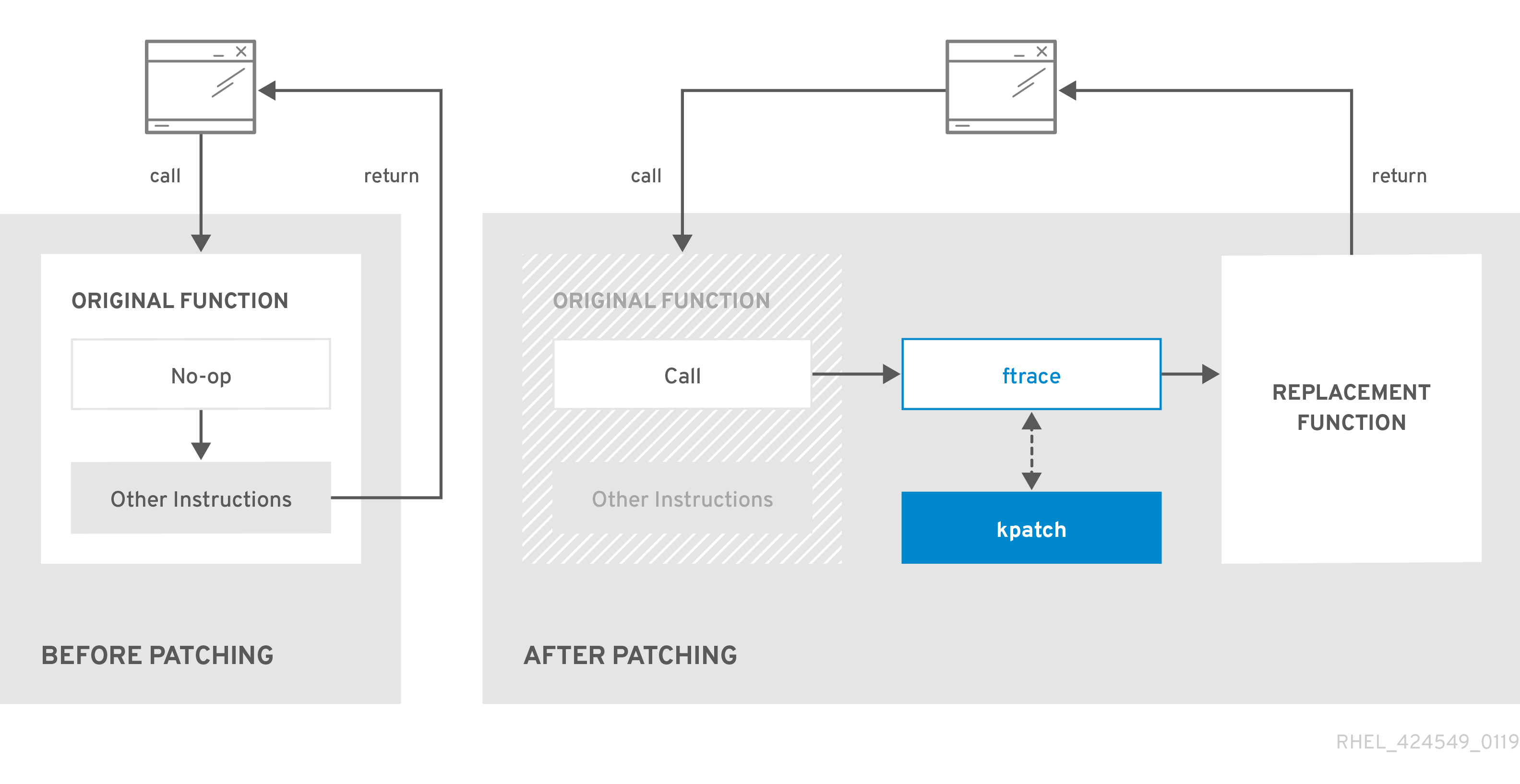
42.5. Subscribing the currently installed kernels to the live patching stream
A kernel patch module is delivered in an RPM package, specific to the version of the kernel being patched. Each RPM package will be cumulatively updated over time.
The following procedure explains how to subscribe to all future cumulative live patching updates for a given kernel. Because live patches are cumulative, you cannot select which individual patches are deployed for a given kernel.
Red Hat does not support any third party live patches applied to a Red Hat supported system.
Prerequisites
- You have root permissions.
Procedure
Optional: Check your kernel version:
# uname -r 4.18.0-94.el8.x86_64Search for a live patching package that corresponds to the version of your kernel:
# yum search $(uname -r)Install the live patching package:
# yum install "kpatch-patch = $(uname -r)"The command above installs and applies the latest cumulative live patches for that specific kernel only.
If the version of a live patching package is 1-1 or higher, the package will contain a patch module. In that case the kernel will be automatically patched during the installation of the live patching package.
The kernel patch module is also installed into the
/var/lib/kpatch/directory to be loaded by thesystemdsystem and service manager during the future reboots.NoteAn empty live patching package will be installed when there are no live patches available for a given kernel. An empty live patching package will have a kpatch_version-kpatch_release of 0-0, for example
kpatch-patch-4_18_0-94-0-0.el8.x86_64.rpm. The installation of the empty RPM subscribes the system to all future live patches for the given kernel.
Verification
Verify that all installed kernels have been patched:
# kpatch list Loaded patch modules: kpatch_4_18_0_94_1_1 [enabled] Installed patch modules: kpatch_4_18_0_94_1_1 (4.18.0-94.el8.x86_64) …The output shows that the kernel patch module has been loaded into the kernel that is now patched with the latest fixes from the
kpatch-patch-4_18_0-94-1-1.el8.x86_64.rpmpackage.NoteEntering the
kpatch listcommand does not return an empty live patching package. Use therpm -qa | grep kpatchcommand instead.# rpm -qa | grep kpatch kpatch-patch-4_18_0-477_21_1-0-0.el8_8.x86_64 kpatch-dnf-0.9.7_0.4-2.el8.noarch kpatch-0.9.7-2.el8.noarch
42.6. Automatically subscribing any future kernel to the live patching stream
You can use the kpatch-dnf YUM plugin to subscribe your system to fixes delivered by the kernel patch module, also known as kernel live patches. The plugin enables automatic subscription for any kernel the system currently uses, and also for kernels to-be-installed in the future.
Prerequisites
- You have root permissions.
Procedure
Optional: Check all installed kernels and the kernel you are currently running:
# yum list installed | grep kernel Updating Subscription Management repositories. Installed Packages ... kernel-core.x86_64 4.18.0-240.10.1.el8_3 @rhel-8-for-x86_64-baseos-rpms kernel-core.x86_64 4.18.0-240.15.1.el8_3 @rhel-8-for-x86_64-baseos-rpms ... # uname -r 4.18.0-240.10.1.el8_3.x86_64Install the
kpatch-dnfplugin:# yum install kpatch-dnfEnable automatic subscription to kernel live patches:
# yum kpatch auto Updating Subscription Management repositories. Last metadata expiration check: 19:10:26 ago on Wed 10 Mar 2021 04:08:06 PM CET. Dependencies resolved. ================================================== Package Architecture ================================================== Installing: kpatch-patch-4_18_0-240_10_1 x86_64 kpatch-patch-4_18_0-240_15_1 x86_64 Transaction Summary =================================================== Install 2 Packages …This command subscribes all currently installed kernels to receiving kernel live patches. The command also installs and applies the latest cumulative live patches, if any, for all installed kernels.
When you update the kernel, live patches are installed automatically during the new kernel installation process.
The kernel patch module is also installed into the
/var/lib/kpatch/directory to be loaded by thesystemdsystem and service manager during future reboots.NoteAn empty live patching package will be installed when there are no live patches available for a given kernel. An empty live patching package will have a kpatch_version-kpatch_release of 0-0, for example
kpatch-patch-4_18_0-240-0-0.el8.x86_64.rpm. The installation of the empty RPM subscribes the system to all future live patches for the given kernel.
Verification
Verify that all installed kernels are patched:
# kpatch list Loaded patch modules: kpatch_4_18_0_240_10_1_0_1 [enabled] Installed patch modules: kpatch_4_18_0_240_10_1_0_1 (4.18.0-240.10.1.el8_3.x86_64) kpatch_4_18_0_240_15_1_0_2 (4.18.0-240.15.1.el8_3.x86_64)The output shows that both the kernel you are running, and the other installed kernel have been patched with fixes from
kpatch-patch-4_18_0-240_10_1-0-1.rpmandkpatch-patch-4_18_0-240_15_1-0-1.rpmpackages respectively.NoteEntering the
kpatch listcommand does not return an empty live patching package. Use therpm -qa | grep kpatchcommand instead.# rpm -qa | grep kpatch kpatch-patch-4_18_0-477_21_1-0-0.el8_8.x86_64 kpatch-dnf-0.9.7_0.4-2.el8.noarch kpatch-0.9.7-2.el8.noarch
42.7. Disabling automatic subscription to the live patching stream
When you subscribe your system to fixes delivered by the kernel patch module, your subscription is automatic. You can disable this feature, to disable automatic installation of kpatch-patch packages.
Prerequisites
- You have root permissions.
Procedure
Optional: Check all installed kernels and the kernel you are currently running:
# yum list installed | grep kernel Updating Subscription Management repositories. Installed Packages ... kernel-core.x86_64 4.18.0-240.10.1.el8_3 @rhel-8-for-x86_64-baseos-rpms kernel-core.x86_64 4.18.0-240.15.1.el8_3 @rhel-8-for-x86_64-baseos-rpms ... # uname -r 4.18.0-240.10.1.el8_3.x86_64Disable automatic subscription to kernel live patches:
# yum kpatch manual Updating Subscription Management repositories.
Verification
You can check for the successful outcome:
# yum kpatch status ... Updating Subscription Management repositories. Last metadata expiration check: 0:30:41 ago on Tue Jun 14 15:59:26 2022. Kpatch update setting: manual
42.8. Updating kernel patch modules
The kernel patch modules are delivered and applied through RPM packages. The process of updating a cumulative kernel patch module is similar to updating any other RPM package.
Prerequisites
- The system is subscribed to the live patching stream, as described in Subscribing the currently installed kernels to the live patching stream.
Procedure
Update to a new cumulative version for the current kernel:
# yum update "kpatch-patch = $(uname -r)"The command above automatically installs and applies any updates that are available for the currently running kernel. Including any future released cumulative live patches.
Alternatively, update all installed kernel patch modules:
# yum update "kpatch-patch"
When the system reboots into the same kernel, the kernel is automatically live patched again by the kpatch.service systemd service.
42.9. Removing the live patching package
Disable the Red Hat Enterprise Linux kernel live patching solution by removing the live patching package.
Prerequisites
- Root permissions
- The live patching package is installed.
Procedure
Select the live patching package.
# yum list installed | grep kpatch-patch kpatch-patch-4_18_0-94.x86_64 1-1.el8 @@commandline …The example output lists live patching packages that you installed.
Remove the live patching package.
# yum remove kpatch-patch-4_18_0-94.x86_64When a live patching package is removed, the kernel remains patched until the next reboot, but the kernel patch module is removed from disk. On future reboot, the corresponding kernel will no longer be patched.
- Reboot your system.
Verify the live patching package is removed:
# yum list installed | grep kpatch-patchThe command displays no output if the package has been successfully removed.
Verification
Verify the kernel live patching solution is disabled:
# kpatch list Loaded patch modules:The example output shows that the kernel is not patched and the live patching solution is not active because there are no patch modules that are currently loaded.
Currently, Red Hat does not support reverting live patches without rebooting your system. In case of any issues, contact our support team.
42.10. Uninstalling the kernel patch module
Prevent the Red Hat Enterprise Linux kernel live patching solution from applying a kernel patch module on subsequent boots.
Prerequisites
- Root permissions
- A live patching package is installed.
- A kernel patch module is installed and loaded.
Procedure
Select a kernel patch module:
# kpatch list Loaded patch modules: kpatch_4_18_0_94_1_1 [enabled] Installed patch modules: kpatch_4_18_0_94_1_1 (4.18.0-94.el8.x86_64) …Uninstall the selected kernel patch module.
# kpatch uninstall kpatch_4_18_0_94_1_1 uninstalling kpatch_4_18_0_94_1_1 (4.18.0-94.el8.x86_64)Note that the uninstalled kernel patch module is still loaded:
# kpatch list Loaded patch modules: kpatch_4_18_0_94_1_1 [enabled] Installed patch modules: <NO_RESULT>When the selected module is uninstalled, the kernel remains patched until the next reboot, but the kernel patch module is removed from disk.
- Reboot your system.
Verification
Verify that the kernel patch module is uninstalled:
# kpatch list Loaded patch modules: …This example output shows no loaded or installed kernel patch modules, therefore the kernel is not patched and the kernel live patching solution is not active.
42.11. Disabling kpatch.service
Prevent the Red Hat Enterprise Linux kernel live patching solution from applying all kernel patch modules globally on subsequent boots.
Prerequisites
- Root permissions
- A live patching package is installed.
- A kernel patch module is installed and loaded.
Procedure
Verify
kpatch.serviceis enabled.# systemctl is-enabled kpatch.service enabledDisable
kpatch.service.# systemctl disable kpatch.service Removed /etc/systemd/system/multi-user.target.wants/kpatch.service.Note that the applied kernel patch module is still loaded:
# kpatch list Loaded patch modules: kpatch_4_18_0_94_1_1 [enabled] Installed patch modules: kpatch_4_18_0_94_1_1 (4.18.0-94.el8.x86_64)
- Reboot your system.
Optional: Verify the status of
kpatch.service.# systemctl status kpatch.service ● kpatch.service - "Apply kpatch kernel patches" Loaded: loaded (/usr/lib/systemd/system/kpatch.service; disabled; vendor preset: disabled) Active: inactive (dead)The example output testifies that
kpatch.serviceis disabled. Thereby, the kernel live patching solution is not active.Verify that the kernel patch module has been unloaded.
# kpatch list Loaded patch modules: <NO_RESULT> Installed patch modules: kpatch_4_18_0_94_1_1 (4.18.0-94.el8.x86_64)The example output above shows that a kernel patch module is still installed but the kernel is not patched.
Currently, Red Hat does not support reverting live patches without rebooting your system. In case of any issues, contact our support team.
Chapter 43. Setting system resource limits for applications by using control groups
Using the control groups (cgroups) kernel functionality, you can control resource usage of applications to use them more efficiently.
You can use cgroups for the following tasks:
- Setting limits for system resource allocation.
- Prioritizing the allocation of hardware resources to specific processes.
- Isolating certain processes from obtaining hardware resources.
43.1. Introducing control groups
Using the control groups Linux kernel feature, you can organize processes into hierarchically ordered groups - cgroups. You define the hierarchy (control groups tree) by providing structure to cgroups virtual file system, mounted by default on the /sys/fs/cgroup/ directory.
The systemd service manager uses cgroups to organize all units and services that it governs. Manually, you can manage the hierarchies of cgroups by creating and removing sub-directories in the /sys/fs/cgroup/ directory.
The resource controllers in the kernel then modify the behavior of processes in cgroups by limiting, prioritizing or allocating system resources, of those processes. These resources include the following:
- CPU time
- Memory
- Network bandwidth
- Combinations of these resources
The primary use case of cgroups is aggregating system processes and dividing hardware resources among applications and users. This makes it possible to increase the efficiency, stability, and security of your environment.
- Control groups version 1
Control groups version 1 (
cgroups-v1) provide a per-resource controller hierarchy. Each resource, such as CPU, memory, or I/O, has its own control group hierarchy. You can combine different control group hierarchies in a way that one controller can coordinate with another in managing their respective resources. However, when the two controllers belong to different process hierarchies, the coordination is limited.The
cgroups-v1controllers were developed across a large time span, resulting in inconsistent behavior and naming of their control files.- Control groups version 2
Control groups version 2 (
cgroups-v2) provide a single control group hierarchy against which all resource controllers are mounted.The control file behavior and naming is consistent among different controllers.
Notecgroups-v2is fully supported in RHEL 8.2 and later versions. For more information, see Control Group v2 is now fully supported in RHEL 8.
43.2. Introducing kernel resource controllers
Kernel resource controllers enable the functionality of control groups. RHEL 8 supports various controllers for control groups version 1 (cgroups-v1) and control groups version 2 (cgroups-v2).
A resource controller, also called a control group subsystem, is a kernel subsystem that represents a single resource, such as CPU time, memory, network bandwidth or disk I/O. The Linux kernel provides a range of resource controllers that are mounted automatically by the systemd service manager. You can find a list of the currently mounted resource controllers in the /proc/cgroups file.
Controllers available for cgroups-v1:
blkio- Sets limits on input/output access to and from block devices.
cpu-
Adjusts the parameters of the Completely Fair Scheduler (CFS) for a control group’s tasks. The
cpucontroller is mounted together with thecpuacctcontroller on the same mount. cpuacct-
Creates automatic reports on CPU resources used by tasks in a control group. The
cpuacctcontroller is mounted together with thecpucontroller on the same mount. cpuset- Restricts control group tasks to run only on a specified subset of CPUs and to direct the tasks to use memory only on specified memory nodes.
devices- Controls access to devices for tasks in a control group.
freezer- Suspends or resumes tasks in a control group.
memory- Sets limits on memory use by tasks in a control group and generates automatic reports on memory resources used by those tasks.
net_cls-
Tags network packets with a class identifier (
classid) that enables the Linux traffic controller (thetccommand) to identify packets that originate from a particular control group task. A subsystem ofnet_cls, thenet_filter(iptables), can also use this tag to perform actions on such packets. Thenet_filtertags network sockets with a firewall identifier (fwid) that allows the Linux firewall to identify packets that originate from a particular control group task (by using theiptablescommand). net_prio- Sets the priority of network traffic.
pids- Sets limits for multiple processes and their children in a control group.
perf_event-
Groups tasks for monitoring by the
perfperformance monitoring and reporting utility. rdma- Sets limits on Remote Direct Memory Access/InfiniBand specific resources in a control group.
hugetlb- Limits the usage of large size virtual memory pages by tasks in a control group.
Controllers available for cgroups-v2:
io- Sets limits on input/output access to and from block devices.
memory- Sets limits on memory use by tasks in a control group and generates automatic reports on memory resources used by those tasks.
pids- Sets limits for multiple processes and their children in a control group.
rdma- Sets limits on Remote Direct Memory Access/InfiniBand specific resources in a control group.
cpu- Adjusts the parameters of the Completely Fair Scheduler (CFS) for a control group’s tasks and creates automatic reports on CPU resources used by tasks in a control group.
cpuset-
Restricts control group tasks to run only on a specified subset of CPUs and to direct the tasks to use memory only on specified memory nodes. Supports only the core functionality (
cpus{,.effective},mems{,.effective}) with a new partition feature. perf_event-
Groups tasks for monitoring by the
perfperformance monitoring and reporting utility.perf_eventis enabled automatically on the v2 hierarchy.
A resource controller can be used either in a cgroups-v1 hierarchy or a cgroups-v2 hierarchy, not simultaneously in both.
43.3. Introducing namespaces
Namespaces create separate spaces for organizing and identifying software objects. This keeps them from affecting each other. As a result, each software object contains its own set of resources, for example, a mount point, a network device, or a a hostname, even though they are sharing the same system.
One of the most common technologies that use namespaces are containers.
Changes to a particular global resource are visible only to processes in that namespace and do not affect the rest of the system or other namespaces.
To inspect which namespaces a process is a member of, you can check the symbolic links in the /proc/<PID>/ns/ directory.
| Namespace | Isolates |
|---|---|
| Mount | Mount points |
| UTS | Hostname and NIS domain name |
| IPC | System V IPC, POSIX message queues |
| PID | Process IDs |
| Network | Network devices, stacks, ports, etc |
| User | User and group IDs |
| Control groups | Control group root directory |
43.4. Setting CPU limits to applications using cgroups-v1
To configure CPU limits to an application by using control groups version 1 (cgroups-v1), use the /sys/fs/ virtual file system.
Prerequisites
- You have root permissions.
- You have an application to restrict its CPU consumption installed on your system.
You verified that the
cgroups-v1controllers are mounted:# mount -l | grep cgroup tmpfs on /sys/fs/cgroup type tmpfs (ro,nosuid,nodev,noexec,seclabel,mode=755) cgroup on /sys/fs/cgroup/systemd type cgroup (rw,nosuid,nodev,noexec,relatime,seclabel,xattr,release_agent=/usr/lib/systemd/systemd-cgroups-agent,name=systemd) cgroup on /sys/fs/cgroup/cpu,cpuacct type cgroup (rw,nosuid,nodev,noexec,relatime,seclabel,cpu,cpuacct) cgroup on /sys/fs/cgroup/perf_event type cgroup (rw,nosuid,nodev,noexec,relatime,seclabel,perf_event) cgroup on /sys/fs/cgroup/pids type cgroup (rw,nosuid,nodev,noexec,relatime,seclabel,pids) ...
Procedure
Identify the process ID (PID) of the application that you want to restrict in CPU consumption:
# top top - 11:34:09 up 11 min, 1 user, load average: 0.51, 0.27, 0.22 Tasks: 267 total, 3 running, 264 sleeping, 0 stopped, 0 zombie %Cpu(s): 49.0 us, 3.3 sy, 0.0 ni, 47.5 id, 0.0 wa, 0.2 hi, 0.0 si, 0.0 st MiB Mem : 1826.8 total, 303.4 free, 1046.8 used, 476.5 buff/cache MiB Swap: 1536.0 total, 1396.0 free, 140.0 used. 616.4 avail Mem PID USER PR NI VIRT RES SHR S %CPU %MEM TIME+ COMMAND 6955 root 20 0 228440 1752 1472 R 99.3 0.1 0:32.71 sha1sum 5760 jdoe 20 0 3603868 205188 64196 S 3.7 11.0 0:17.19 gnome-shell 6448 jdoe 20 0 743648 30640 19488 S 0.7 1.6 0:02.73 gnome-terminal- 1 root 20 0 245300 6568 4116 S 0.3 0.4 0:01.87 systemd 505 root 20 0 0 0 0 I 0.3 0.0 0:00.75 kworker/u4:4-events_unbound ...The
sha1sumexample application withPID 6955consumes a large amount of CPU resources.Create a sub-directory in the
cpuresource controller directory:# mkdir /sys/fs/cgroup/cpu/Example/This directory represents a control group, where you can place specific processes and apply certain CPU limits to the processes. At the same time, a number of
cgroups-v1interface files andcpucontroller-specific files will be created in the directory.Optional: Inspect the newly created control group:
# ll /sys/fs/cgroup/cpu/Example/ -rw-r—r--. 1 root root 0 Mar 11 11:42 cgroup.clone_children -rw-r—r--. 1 root root 0 Mar 11 11:42 cgroup.procs -r—r—r--. 1 root root 0 Mar 11 11:42 cpuacct.stat -rw-r—r--. 1 root root 0 Mar 11 11:42 cpuacct.usage -r—r—r--. 1 root root 0 Mar 11 11:42 cpuacct.usage_all -r—r—r--. 1 root root 0 Mar 11 11:42 cpuacct.usage_percpu -r—r—r--. 1 root root 0 Mar 11 11:42 cpuacct.usage_percpu_sys -r—r—r--. 1 root root 0 Mar 11 11:42 cpuacct.usage_percpu_user -r—r—r--. 1 root root 0 Mar 11 11:42 cpuacct.usage_sys -r—r—r--. 1 root root 0 Mar 11 11:42 cpuacct.usage_user -rw-r—r--. 1 root root 0 Mar 11 11:42 cpu.cfs_period_us -rw-r—r--. 1 root root 0 Mar 11 11:42 cpu.cfs_quota_us -rw-r—r--. 1 root root 0 Mar 11 11:42 cpu.rt_period_us -rw-r—r--. 1 root root 0 Mar 11 11:42 cpu.rt_runtime_us -rw-r—r--. 1 root root 0 Mar 11 11:42 cpu.shares -r—r—r--. 1 root root 0 Mar 11 11:42 cpu.stat -rw-r—r--. 1 root root 0 Mar 11 11:42 notify_on_release -rw-r—r--. 1 root root 0 Mar 11 11:42 tasksFiles, such as
cpuacct.usage,cpu.cfs._period_usrepresent specific configurations and/or limits, which can be set for processes in theExamplecontrol group. Note that the file names are prefixed with the name of the control group controller they belong to.By default, the newly created control group inherits access to the system’s entire CPU resources without a limit.
Configure CPU limits for the control group:
# echo "1000000" > /sys/fs/cgroup/cpu/Example/cpu.cfs_period_us # echo "200000" > /sys/fs/cgroup/cpu/Example/cpu.cfs_quota_us-
The
cpu.cfs_period_usfile represents how frequently a control group’s access to CPU resources must be reallocated. The time period is in microseconds (µs, "us"). The upper limit is 1 000 000 microseconds and the lower limit is 1000 microseconds. The
cpu.cfs_quota_usfile represents the total amount of time in microseconds for which all processes in a control group can collectively run during one period, as defined bycpu.cfs_period_us. When processes in a control group use up all the time specified by the quota during a single period, they are throttled for the remainder of the period and not allowed to run until the next period. The lower limit is 1000 microseconds.The example commands above set the CPU time limits so that all processes collectively in the
Examplecontrol group will be able to run only for 0.2 seconds (defined bycpu.cfs_quota_us) out of every 1 second (defined bycpu.cfs_period_us).
-
The
Optional: Verify the limits:
# cat /sys/fs/cgroup/cpu/Example/cpu.cfs_period_us /sys/fs/cgroup/cpu/Example/cpu.cfs_quota_us 1000000 200000Add the application’s PID to the
Examplecontrol group:# echo "6955" > /sys/fs/cgroup/cpu/Example/cgroup.procsThis command ensures that a specific application becomes a member of the
Examplecontrol group and does not exceed the CPU limits configured for theExamplecontrol group. The PID must represent an existing process in the system. ThePID 6955here was assigned to thesha1sum /dev/zero &process, used to illustrate the use case of thecpucontroller.
Verification
Verify that the application runs in the specified control group:
# cat /proc/6955/cgroup 12:cpuset:/ 11:hugetlb:/ 10:net_cls,net_prio:/ 9:memory:/user.slice/user-1000.slice/user@1000.service 8:devices:/user.slice 7:blkio:/ 6:freezer:/ 5:rdma:/ 4:pids:/user.slice/user-1000.slice/user@1000.service 3:perf_event:/ 2:cpu,cpuacct:/Example 1:name=systemd:/user.slice/user-1000.slice/user@1000.service/gnome-terminal-server.serviceThe process of an application runs in the
Examplecontrol group applying CPU limits to the application’s process.Identify the current CPU consumption of your throttled application:
# top top - 12:28:42 up 1:06, 1 user, load average: 1.02, 1.02, 1.00 Tasks: 266 total, 6 running, 260 sleeping, 0 stopped, 0 zombie %Cpu(s): 11.0 us, 1.2 sy, 0.0 ni, 87.5 id, 0.0 wa, 0.2 hi, 0.0 si, 0.2 st MiB Mem : 1826.8 total, 287.1 free, 1054.4 used, 485.3 buff/cache MiB Swap: 1536.0 total, 1396.7 free, 139.2 used. 608.3 avail Mem PID USER PR NI VIRT RES SHR S %CPU %MEM TIME+ COMMAND 6955 root 20 0 228440 1752 1472 R 20.6 0.1 47:11.43 sha1sum 5760 jdoe 20 0 3604956 208832 65316 R 2.3 11.2 0:43.50 gnome-shell 6448 jdoe 20 0 743836 31736 19488 S 0.7 1.7 0:08.25 gnome-terminal- 505 root 20 0 0 0 0 I 0.3 0.0 0:03.39 kworker/u4:4-events_unbound 4217 root 20 0 74192 1612 1320 S 0.3 0.1 0:01.19 spice-vdagentd ...Note that the CPU consumption of the
PID 6955has decreased from 99% to 20%.
The cgroups-v2 counterpart for cpu.cfs_period_us and cpu.cfs_quota_us is the cpu.max file. The cpu.max file is available through the cpu controller.
Chapter 44. Analyzing system performance with BPF Compiler Collection
The BPF Compiler Collection (BCC) analyzes system performance by combining the capabilities of Berkeley Packet Filter (BPF). With BPF, you can safely run the custom programs within the kernel to access system events and data for performance monitoring, tracing, and debugging. BCC simplifies the development and deployment of BPF programs with tools and libraries for users to extract important insights from their systems.
44.1. Installing the bcc-tools package
Install the bcc-tools package, which also installs the BPF Compiler Collection (BCC) library as a dependency.
Procedure
Install
bcc-tools.# yum install bcc-toolsThe BCC tools are installed in the
/usr/share/bcc/tools/directory.
Verification
Inspect the installed tools:
# ls -l /usr/share/bcc/tools/ ... -rwxr-xr-x. 1 root root 4198 Dec 14 17:53 dcsnoop -rwxr-xr-x. 1 root root 3931 Dec 14 17:53 dcstat -rwxr-xr-x. 1 root root 20040 Dec 14 17:53 deadlock_detector -rw-r--r--. 1 root root 7105 Dec 14 17:53 deadlock_detector.c drwxr-xr-x. 3 root root 8192 Mar 11 10:28 doc -rwxr-xr-x. 1 root root 7588 Dec 14 17:53 execsnoop -rwxr-xr-x. 1 root root 6373 Dec 14 17:53 ext4dist -rwxr-xr-x. 1 root root 10401 Dec 14 17:53 ext4slower ...The
docdirectory in the listing provides documentation for each tool.
44.2. Using selected bcc-tools for performance analyses
Use certain pre-created programs from the BPF Compiler Collection (BCC) library to efficiently and securely analyze the system performance on the per-event basis. The set of pre-created programs in the BCC library can serve as examples for creation of additional programs.
Prerequisites
- Installed bcc-tools package
- Root permissions
Procedure
- Using
execsnoopto examine the system processes -
Run the
execsnoopprogram in one terminal:
# /usr/share/bcc/tools/execsnoopTo create a short-lived process of the
lscommand, in another terminal, enter:$ ls /usr/share/bcc/tools/doc/The terminal running
execsnoopshows the output similar to the following:PCOMM PID PPID RET ARGS ls 8382 8287 0 /usr/bin/ls --color=auto /usr/share/bcc/tools/doc/ ...The
execsnoopprogram prints a line of output for each new process that consume system resources. It even detects processes of programs that run very shortly, such asls, and most monitoring tools would not register them.The
execsnoopoutput displays the following fields:
-
Run the
- PCOMM
-
The parent process name. (
ls) - PID
-
The process ID. (
8382) - PPID
-
The parent process ID. (
8287) - RET
-
The return value of the
exec()system call (0), which loads program code into new processes. - ARGS
- The location of the started program with arguments.
To see more details, examples, and options for execsnoop, see /usr/share/bcc/tools/doc/execsnoop_example.txt file.
For more information about exec(), see exec(3) manual pages.
- Using
opensnoopto track what files a command opens -
In one terminal, run the
opensnoopprogram to print the output for files opened only by the process of theunamecommand:
# /usr/share/bcc/tools/opensnoop -n unameIn another terminal, enter the command to open certain files:
$ unameThe terminal running
opensnoopshows the output similar to the following:PID COMM FD ERR PATH 8596 uname 3 0 /etc/ld.so.cache 8596 uname 3 0 /lib64/libc.so.6 8596 uname 3 0 /usr/lib/locale/locale-archive ...The
opensnoopprogram watches theopen()system call across the whole system, and prints a line of output for each file thatunametried to open along the way.The
opensnoopoutput displays the following fields:- PID
-
The process ID. (
8596) - COMM
-
The process name. (
uname) - FD
-
The file descriptor - a value that
open()returns to refer to the open file. (3) - ERR
- Any errors.
- PATH
-
The location of files that
open()tried to open.
If a command tries to read a non-existent file, then the
FDcolumn returns-1and theERRcolumn prints a value corresponding to the relevant error. As a result,opensnoopcan help you identify an application that does not behave properly.
-
In one terminal, run the
To see more details, examples, and options for opensnoop, see /usr/share/bcc/tools/doc/opensnoop_example.txt file.
For more information about open(), see open(2) manual pages.
- Use the
biotopto monitor the top processes performing I/O operations on the disk -
Run the
biotopprogram in one terminal with argument30to produce 30 second summary:
# /usr/share/bcc/tools/biotop 30NoteWhen no argument provided, the output screen by default refreshes every 1 second.
In another terminal, enter command to read the content from the local hard disk device and write the output to the
/dev/zerofile:# dd if=/dev/vda of=/dev/zeroThis step generates certain I/O traffic to illustrate
biotop.The terminal running
biotopshows the output similar to the following:PID COMM D MAJ MIN DISK I/O Kbytes AVGms 9568 dd R 252 0 vda 16294 14440636.0 3.69 48 kswapd0 W 252 0 vda 1763 120696.0 1.65 7571 gnome-shell R 252 0 vda 834 83612.0 0.33 1891 gnome-shell R 252 0 vda 1379 19792.0 0.15 7515 Xorg R 252 0 vda 280 9940.0 0.28 7579 llvmpipe-1 R 252 0 vda 228 6928.0 0.19 9515 gnome-control-c R 252 0 vda 62 6444.0 0.43 8112 gnome-terminal- R 252 0 vda 67 2572.0 1.54 7807 gnome-software R 252 0 vda 31 2336.0 0.73 9578 awk R 252 0 vda 17 2228.0 0.66 7578 llvmpipe-0 R 252 0 vda 156 2204.0 0.07 9581 pgrep R 252 0 vda 58 1748.0 0.42 7531 InputThread R 252 0 vda 30 1200.0 0.48 7504 gdbus R 252 0 vda 3 1164.0 0.30 1983 llvmpipe-1 R 252 0 vda 39 724.0 0.08 1982 llvmpipe-0 R 252 0 vda 36 652.0 0.06 ...The
biotopoutput displays the following fields:
-
Run the
- PID
-
The process ID. (
9568) - COMM
-
The process name. (
dd) - DISK
-
The disk performing the read operations. (
vda) - I/O
- The number of read operations performed. (16294)
- Kbytes
- The amount of Kbytes reached by the read operations. (14,440,636)
- AVGms
- The average I/O time of read operations. (3.69)
For more details, examples, and options for biotop, see the /usr/share/bcc/tools/doc/biotop_example.txt file.
For more information about dd, see dd(1) manual pages.
Using xfsslower to expose unexpectedly slow file system operations
The xfsslower measures the time spent by XFS file system in performing read, write, open or sync (fsync) operations. The 1 argument ensures that the program shows only the operations that are slower than 1 ms.
Run the
xfsslowerprogram in one terminal:# /usr/share/bcc/tools/xfsslower 1NoteWhen no arguments provided,
xfsslowerby default displays operations slower than 10 ms.In another terminal, enter the command to create a text file in the
vimeditor to start interaction with the XFS file system:$ vim textThe terminal running
xfsslowershows something similar upon saving the file from the previous step:TIME COMM PID T BYTES OFF_KB LAT(ms) FILENAME 13:07:14 b'bash' 4754 R 256 0 7.11 b'vim' 13:07:14 b'vim' 4754 R 832 0 4.03 b'libgpm.so.2.1.0' 13:07:14 b'vim' 4754 R 32 20 1.04 b'libgpm.so.2.1.0' 13:07:14 b'vim' 4754 R 1982 0 2.30 b'vimrc' 13:07:14 b'vim' 4754 R 1393 0 2.52 b'getscriptPlugin.vim' 13:07:45 b'vim' 4754 S 0 0 6.71 b'text' 13:07:45 b'pool' 2588 R 16 0 5.58 b'text' ...Each line represents an operation in the file system, which took more time than a certain threshold.
xfsslowerdetects possible file system problems, which can take form of unexpectedly slow operations.The
xfssloweroutput displays the following fields:- COMM
-
The process name. (
b’bash') - T
The operation type. (
R)- Read
- Write
- Sync
- OFF_KB
- The file offset in KB. (0)
- FILENAME
- The file that is read, written, or synced.
To see more details, examples, and options for xfsslower, see /usr/share/bcc/tools/doc/xfsslower_example.txt file.
For more information about fsync, see fsync(2) manual pages.
Part VII. Design of high availability system
Chapter 45. High Availability Add-On overview
The High Availability Add-On is a clustered system that provides reliability, scalability, and availability to critical production services.
A cluster is two or more computers (called nodes or members) that work together to perform a task. Clusters can be used to provide highly available services or resources. The redundancy of multiple machines is used to guard against failures of many types.
High availability clusters provide highly available services by eliminating single points of failure and by failing over services from one cluster node to another in case a node becomes inoperative. Typically, services in a high availability cluster read and write data (by means of read-write mounted file systems). Therefore, a high availability cluster must maintain data integrity as one cluster node takes over control of a service from another cluster node. Node failures in a high availability cluster are not visible from clients outside the cluster. (High availability clusters are sometimes referred to as failover clusters.) The High Availability Add-On provides high availability clustering through its high availability service management component, Pacemaker.
Red Hat provides a variety of documentation for planning, configuring, and maintaining a Red Hat high availability cluster. For a listing of articles that provide guided indexes to the various areas of Red Hat cluster documentation, see the Red Hat High Availability Add-On Documentation Guide.
45.1. High Availability Add-On components
The Red Hat High Availability Add-On consists of several components that provide the high availability service.
The major components of the High Availability Add-On are as follows:
- Cluster infrastructure - Provides fundamental functions for nodes to work together as a cluster: configuration file management, membership management, lock management, and fencing.
- High availability service management - Provides failover of services from one cluster node to another in case a node becomes inoperative.
- Cluster administration tools - Configuration and management tools for setting up, configuring, and managing the High Availability Add-On. The tools are for use with the cluster infrastructure components, the high availability and service management components, and storage.
You can supplement the High Availability Add-On with the following components:
- Red Hat GFS2 (Global File System 2) - Part of the Resilient Storage Add-On, this provides a cluster file system for use with the High Availability Add-On. GFS2 allows multiple nodes to share storage at a block level as if the storage were connected locally to each cluster node. GFS2 cluster file system requires a cluster infrastructure.
-
LVM Locking Daemon (
lvmlockd) - Part of the Resilient Storage Add-On, this provides volume management of cluster storage.lvmlockdsupport also requires cluster infrastructure. - HAProxy - Routing software that provides high availability load balancing and failover in layer 4 (TCP) and layer 7 (HTTP, HTTPS) services.
45.2. High Availability Add-On concepts
Some of the key concepts of a Red Hat High Availability Add-On cluster are as follows.
45.2.1. Fencing
If communication with a single node in the cluster fails, then other nodes in the cluster must be able to restrict or release access to resources that the failed cluster node may have access to. his cannot be accomplished by contacting the cluster node itself as the cluster node may not be responsive. Instead, you must provide an external method, which is called fencing with a fence agent. A fence device is an external device that can be used by the cluster to restrict access to shared resources by an errant node, or to issue a hard reboot on the cluster node.
Without a fence device configured you do not have a way to know that the resources previously used by the disconnected cluster node have been released, and this could prevent the services from running on any of the other cluster nodes. Conversely, the system may assume erroneously that the cluster node has released its resources and this can lead to data corruption and data loss. Without a fence device configured data integrity cannot be guaranteed and the cluster configuration will be unsupported.
When the fencing is in progress no other cluster operation is allowed to run. Normal operation of the cluster cannot resume until fencing has completed or the cluster node rejoins the cluster after the cluster node has been rebooted.
For more information about fencing, see the Red Hat Knowledgebase solution Fencing in a Red Hat High Availability Cluster.
45.2.2. Quorum
In order to maintain cluster integrity and availability, cluster systems use a concept known as quorum to prevent data corruption and loss. A cluster has quorum when more than half of the cluster nodes are online. To mitigate the chance of data corruption due to failure, Pacemaker by default stops all resources if the cluster does not have quorum.
Quorum is established using a voting system. When a cluster node does not function as it should or loses communication with the rest of the cluster, the majority working nodes can vote to isolate and, if needed, fence the node for servicing.
For example, in a 6-node cluster, quorum is established when at least 4 cluster nodes are functioning. If the majority of nodes go offline or become unavailable, the cluster no longer has quorum and Pacemaker stops clustered services.
The quorum features in Pacemaker prevent what is also known as split-brain, a phenomenon where the cluster is separated from communication but each part continues working as separate clusters, potentially writing to the same data and possibly causing corruption or loss. For more information about what it means to be in a split-brain state, and on quorum concepts in general, see the Red Hat Knowledgebase article Exploring Concepts of RHEL High Availability Clusters - Quorum.
A Red Hat Enterprise Linux High Availability Add-On cluster uses the votequorum service, in conjunction with fencing, to avoid split brain situations. A number of votes is assigned to each system in the cluster, and cluster operations are allowed to proceed only when a majority of votes is present.
45.2.3. Cluster resources
A cluster resource is an instance of a program, data, or application to be managed by the cluster service. These resources are abstracted by agents that provide a standard interface for managing the resource in a cluster environment.
To ensure that resources remain healthy, you can add a monitoring operation to a resource’s definition. If you do not specify a monitoring operation for a resource, one is added by default.
You can determine the behavior of a resource in a cluster by configuring constraints. You can configure the following categories of constraints:
- location constraints - A location constraint determines which nodes a resource can run on.
- ordering constraints - An ordering constraint determines the order in which the resources run.
- colocation constraints - A colocation constraint determines where resources will be placed relative to other resources.
One of the most common elements of a cluster is a set of resources that need to be located together, start sequentially, and stop in the reverse order. To simplify this configuration, Pacemaker supports the concept of groups.
45.3. Pacemaker overview
Pacemaker is a cluster resource manager. It achieves maximum availability for your cluster services and resources by making use of the cluster infrastructure’s messaging and membership capabilities to deter and recover from node and resource-level failure.
45.3.1. Pacemaker architecture components
A cluster configured with Pacemaker comprises separate component daemons that monitor cluster membership, scripts that manage the services, and resource management subsystems that monitor the disparate resources.
The following components form the Pacemaker architecture:
- Cluster Information Base (CIB)
- The Pacemaker information daemon, which uses XML internally to distribute and synchronize current configuration and status information from the Designated Coordinator (DC) - a node assigned by Pacemaker to store and distribute cluster state and actions by means of the CIB - to all other cluster nodes.
- Cluster Resource Management Daemon (CRMd)
Pacemaker cluster resource actions are routed through this daemon. Resources managed by CRMd can be queried by client systems, moved, instantiated, and changed when needed.
Each cluster node also includes a local resource manager daemon (LRMd) that acts as an interface between CRMd and resources. LRMd passes commands from CRMd to agents, such as starting and stopping and relaying status information.
- Shoot the Other Node in the Head (STONITH)
- STONITH is the Pacemaker fencing implementation. It acts as a cluster resource in Pacemaker that processes fence requests, forcefully shutting down nodes and removing them from the cluster to ensure data integrity. STONITH is configured in the CIB and can be monitored as a normal cluster resource.
- corosync
corosyncis the component - and a daemon of the same name - that serves the core membership and member-communication needs for high availability clusters. It is required for the High Availability Add-On to function.In addition to those membership and messaging functions,
corosyncalso:- Manages quorum rules and determination.
- Provides messaging capabilities for applications that coordinate or operate across multiple members of the cluster and thus must communicate stateful or other information between instances.
-
Uses the
kronosnetlibrary as its network transport to provide multiple redundant links and automatic failover.
45.3.2. Pacemaker configuration and management tools
The High Availability Add-On features two configuration tools for cluster deployment, monitoring, and management.
pcsThe
pcscommand-line interface controls and configures Pacemaker and thecorosyncheartbeat daemon. A command-line based program,pcscan perform the following cluster management tasks:- Create and configure a Pacemaker/Corosync cluster
- Modify configuration of the cluster while it is running
- Remotely configure both Pacemaker and Corosync as well as start, stop, and display status information of the cluster
pcsdWeb UI- A graphical user interface to create and configure Pacemaker/Corosync clusters.
45.3.3. The cluster and Pacemaker configuration files
The configuration files for the Red Hat High Availability Add-On are corosync.conf and cib.xml.
The corosync.conf file provides the cluster parameters used by corosync, the cluster manager that Pacemaker is built on. In general, you should not edit the corosync.conf directly but, instead, use the pcs or pcsd interface.
The cib.xml file is an XML file that represents both the cluster’s configuration and the current state of all resources in the cluster. This file is used by Pacemaker’s Cluster Information Base (CIB). The contents of the CIB are automatically kept in sync across the entire cluster. Do not edit the cib.xml file directly; use the pcs or pcsd interface instead.
Chapter 46. Getting started with Pacemaker
To familiarize yourself with the tools and processes you use to create a Pacemaker cluster, you can run the following procedures. They are intended for users who are interested in seeing what the cluster software looks like and how it is administered, without needing to configure a working cluster.
These procedures do not create a supported Red Hat cluster, which requires at least two nodes and the configuration of a fencing device. For full information about Red Hat’s support policies, requirements, and limitations for RHEL High Availability clusters, see Support Policies for RHEL High Availability Clusters.
46.1. Learning to use Pacemaker
By working through this procedure, you will learn how to use Pacemaker to set up a cluster, how to display cluster status, and how to configure a cluster service. This example creates an Apache HTTP server as a cluster resource and shows how the cluster responds when the resource fails.
In this example:
-
The node is
z1.example.com. - The floating IP address is 192.168.122.120.
Prerequisites
- A single node running RHEL 8
- A floating IP address that resides on the same network as one of the node’s statically assigned IP addresses
-
The name of the node on which you are running is in your
/etc/hostsfile
Procedure
Install the Red Hat High Availability Add-On software packages from the High Availability channel, and start and enable the
pcsdservice.# yum install pcs pacemaker fence-agents-all ... # systemctl start pcsd.service # systemctl enable pcsd.serviceIf you are running the
firewallddaemon, enable the ports that are required by the Red Hat High Availability Add-On.# firewall-cmd --permanent --add-service=high-availability # firewall-cmd --reloadSet a password for user
haclusteron each node in the cluster and authenticate userhaclusterfor each node in the cluster on the node from which you will be running thepcscommands. This example is using only a single node, the node from which you are running the commands, but this step is included here since it is a necessary step in configuring a supported Red Hat High Availability multi-node cluster.# passwd hacluster ... # pcs host auth z1.example.comCreate a cluster named
my_clusterwith one member and check the status of the cluster. This command creates and starts the cluster in one step.# pcs cluster setup my_cluster --start z1.example.com ... # pcs cluster status Cluster Status: Stack: corosync Current DC: z1.example.com (version 2.0.0-10.el8-b67d8d0de9) - partition with quorum Last updated: Thu Oct 11 16:11:18 2018 Last change: Thu Oct 11 16:11:00 2018 by hacluster via crmd on z1.example.com 1 node configured 0 resources configured PCSD Status: z1.example.com: OnlineA Red Hat High Availability cluster requires that you configure fencing for the cluster. The reasons for this requirement are described in the Red Hat Knowledgebase solution Fencing in a Red Hat High Availability Cluster. For this introduction, however, which is intended to show only how to use the basic Pacemaker commands, disable fencing by setting the
stonith-enabledcluster option tofalse.WarningThe use of
stonith-enabled=falseis completely inappropriate for a production cluster. It tells the cluster to simply pretend that failed nodes are safely fenced.# pcs property set stonith-enabled=falseConfigure a web browser on your system and create a web page to display a simple text message. If you are running the
firewallddaemon, enable the ports that are required byhttpd.NoteDo not use
systemctl enableto enable any services that will be managed by the cluster to start at system boot.# yum install -y httpd wget ... # firewall-cmd --permanent --add-service=http # firewall-cmd --reload # cat <<-END >/var/www/html/index.html <html> <body>My Test Site - $(hostname)</body> </html> ENDIn order for the Apache resource agent to get the status of Apache, create the following addition to the existing configuration to enable the status server URL.
# cat <<-END > /etc/httpd/conf.d/status.conf <Location /server-status> SetHandler server-status Order deny,allow Deny from all Allow from 127.0.0.1 Allow from ::1 </Location> ENDCreate
IPaddr2andapacheresources for the cluster to manage. TheIPaddr2resource is a floating IP address that must not be one already associated with a physical node. If theIPaddr2resource’s NIC device is not specified, the floating IP must reside on the same network as the statically assigned IP address used by the node.You can display a list of all available resource types with the
pcs resource listcommand. You can use thepcs resource describe resourcetypecommand to display the parameters you can set for the specified resource type. For example, the following command displays the parameters you can set for a resource of typeapache:# pcs resource describe apache ...In this example, the IP address resource and the apache resource are both configured as part of a group named
apachegroup, which ensures that the resources are kept together to run on the same node when you are configuring a working multi-node cluster.# pcs resource create ClusterIP ocf:heartbeat:IPaddr2 ip=192.168.122.120 --group apachegroup # pcs resource create WebSite ocf:heartbeat:apache configfile=/etc/httpd/conf/httpd.conf statusurl="http://localhost/server-status" --group apachegroup # pcs status Cluster name: my_cluster Stack: corosync Current DC: z1.example.com (version 2.0.0-10.el8-b67d8d0de9) - partition with quorum Last updated: Fri Oct 12 09:54:33 2018 Last change: Fri Oct 12 09:54:30 2018 by root via cibadmin on z1.example.com 1 node configured 2 resources configured Online: [ z1.example.com ] Full list of resources: Resource Group: apachegroup ClusterIP (ocf::heartbeat:IPaddr2): Started z1.example.com WebSite (ocf::heartbeat:apache): Started z1.example.com PCSD Status: z1.example.com: Online ...After you have configured a cluster resource, you can use the
pcs resource configcommand to display the options that are configured for that resource.# pcs resource config WebSite Resource: WebSite (class=ocf provider=heartbeat type=apache) Attributes: configfile=/etc/httpd/conf/httpd.conf statusurl=http://localhost/server-status Operations: start interval=0s timeout=40s (WebSite-start-interval-0s) stop interval=0s timeout=60s (WebSite-stop-interval-0s) monitor interval=1min (WebSite-monitor-interval-1min)- Point your browser to the website you created using the floating IP address you configured. This should display the text message you defined.
Stop the apache web service and check the cluster status. Using
killall -9simulates an application-level crash.# killall -9 httpdCheck the cluster status. You should see that stopping the web service caused a failed action, but that the cluster software restarted the service and you should still be able to access the website.
# pcs status Cluster name: my_cluster ... Current DC: z1.example.com (version 1.1.13-10.el7-44eb2dd) - partition with quorum 1 node and 2 resources configured Online: [ z1.example.com ] Full list of resources: Resource Group: apachegroup ClusterIP (ocf::heartbeat:IPaddr2): Started z1.example.com WebSite (ocf::heartbeat:apache): Started z1.example.com Failed Resource Actions: * WebSite_monitor_60000 on z1.example.com 'not running' (7): call=13, status=complete, exitreason='none', last-rc-change='Thu Oct 11 23:45:50 2016', queued=0ms, exec=0ms PCSD Status: z1.example.com: OnlineYou can clear the failure status on the resource that failed once the service is up and running again and the failed action notice will no longer appear when you view the cluster status.
# pcs resource cleanup WebSiteWhen you are finished looking at the cluster and the cluster status, stop the cluster services on the node. Even though you have only started services on one node for this introduction, the
--allparameter is included since it would stop cluster services on all nodes on an actual multi-node cluster.# pcs cluster stop --all
46.2. Learning to configure failover
The following procedure provides an introduction to creating a Pacemaker cluster running a service that will fail over from one node to another when the node on which the service is running becomes unavailable. By working through this procedure, you can learn how to create a service in a two-node cluster and you can then observe what happens to that service when it fails on the node on which it running.
This example procedure configures a two-node Pacemaker cluster running an Apache HTTP server. You can then stop the Apache service on one node to see how the service remains available.
In this example:
-
The nodes are
z1.example.comandz2.example.com. - The floating IP address is 192.168.122.120.
Prerequisites
- Two nodes running RHEL 8 that can communicate with each other
- A floating IP address that resides on the same network as one of the node’s statically assigned IP addresses
-
The name of the node on which you are running is in your
/etc/hostsfile
Procedure
On both nodes, install the Red Hat High Availability Add-On software packages from the High Availability channel, and start and enable the
pcsdservice.# yum install pcs pacemaker fence-agents-all ... # systemctl start pcsd.service # systemctl enable pcsd.serviceIf you are running the
firewallddaemon, on both nodes enable the ports that are required by the Red Hat High Availability Add-On.# firewall-cmd --permanent --add-service=high-availability # firewall-cmd --reloadOn both nodes in the cluster, set a password for user
hacluster.# passwd haclusterAuthenticate user
haclusterfor each node in the cluster on the node from which you will be running thepcscommands.# pcs host auth z1.example.com z2.example.comCreate a cluster named
my_clusterwith both nodes as cluster members. This command creates and starts the cluster in one step. You only need to run this from one node in the cluster becausepcsconfiguration commands take effect for the entire cluster.On one node in cluster, run the following command.
# pcs cluster setup my_cluster --start z1.example.com z2.example.comA Red Hat High Availability cluster requires that you configure fencing for the cluster. The reasons for this requirement are described in the Red Hat Knowledgebase solution Fencing in a Red Hat High Availability Cluster. For this introduction, however, to show only how failover works in this configuration, disable fencing by setting the
stonith-enabledcluster option tofalse.WarningThe use of
stonith-enabled=falseis completely inappropriate for a production cluster. It tells the cluster to simply pretend that failed nodes are safely fenced.# pcs property set stonith-enabled=falseAfter creating a cluster and disabling fencing, check the status of the cluster.
NoteWhen you run the
pcs cluster statuscommand, it may show output that temporarily differs slightly from the examples as the system components start up.# pcs cluster status Cluster Status: Stack: corosync Current DC: z1.example.com (version 2.0.0-10.el8-b67d8d0de9) - partition with quorum Last updated: Thu Oct 11 16:11:18 2018 Last change: Thu Oct 11 16:11:00 2018 by hacluster via crmd on z1.example.com 2 nodes configured 0 resources configured PCSD Status: z1.example.com: Online z2.example.com: OnlineOn both nodes, configure a web browser and create a web page to display a simple text message. If you are running the
firewallddaemon, enable the ports that are required byhttpd.NoteDo not use
systemctl enableto enable any services that will be managed by the cluster to start at system boot.# yum install -y httpd wget ... # firewall-cmd --permanent --add-service=http # firewall-cmd --reload # cat <<-END >/var/www/html/index.html <html> <body>My Test Site - $(hostname)</body> </html> ENDIn order for the Apache resource agent to get the status of Apache, on each node in the cluster create the following addition to the existing configuration to enable the status server URL.
# cat <<-END > /etc/httpd/conf.d/status.conf <Location /server-status> SetHandler server-status Order deny,allow Deny from all Allow from 127.0.0.1 Allow from ::1 </Location> ENDCreate
IPaddr2andapacheresources for the cluster to manage. TheIPaddr2resource is a floating IP address that must not be one already associated with a physical node. If theIPaddr2resource’s NIC device is not specified, the floating IP must reside on the same network as the statically assigned IP address used by the node.You can display a list of all available resource types with the
pcs resource listcommand. You can use thepcs resource describe resourcetypecommand to display the parameters you can set for the specified resource type. For example, the following command displays the parameters you can set for a resource of typeapache:# pcs resource describe apache ...In this example, the IP address resource and the apache resource are both configured as part of a group named
apachegroup, which ensures that the resources are kept together to run on the same node.Run the following commands from one node in the cluster:
# pcs resource create ClusterIP ocf:heartbeat:IPaddr2 ip=192.168.122.120 --group apachegroup # pcs resource create WebSite ocf:heartbeat:apache configfile=/etc/httpd/conf/httpd.conf statusurl="http://localhost/server-status" --group apachegroup # pcs status Cluster name: my_cluster Stack: corosync Current DC: z1.example.com (version 2.0.0-10.el8-b67d8d0de9) - partition with quorum Last updated: Fri Oct 12 09:54:33 2018 Last change: Fri Oct 12 09:54:30 2018 by root via cibadmin on z1.example.com 2 nodes configured 2 resources configured Online: [ z1.example.com z2.example.com ] Full list of resources: Resource Group: apachegroup ClusterIP (ocf::heartbeat:IPaddr2): Started z1.example.com WebSite (ocf::heartbeat:apache): Started z1.example.com PCSD Status: z1.example.com: Online z2.example.com: Online ...Note that in this instance, the
apachegroupservice is running on node z1.example.com.Access the website you created, stop the service on the node on which it is running, and note how the service fails over to the second node.
- Point a browser to the website you created using the floating IP address you configured. This should display the text message you defined, displaying the name of the node on which the website is running.
Stop the apache web service. Using
killall -9simulates an application-level crash.# killall -9 httpdCheck the cluster status. You should see that stopping the web service caused a failed action, but that the cluster software restarted the service on the node on which it had been running and you should still be able to access the web browser.
# pcs status Cluster name: my_cluster Stack: corosync Current DC: z1.example.com (version 2.0.0-10.el8-b67d8d0de9) - partition with quorum Last updated: Fri Oct 12 09:54:33 2018 Last change: Fri Oct 12 09:54:30 2018 by root via cibadmin on z1.example.com 2 nodes configured 2 resources configured Online: [ z1.example.com z2.example.com ] Full list of resources: Resource Group: apachegroup ClusterIP (ocf::heartbeat:IPaddr2): Started z1.example.com WebSite (ocf::heartbeat:apache): Started z1.example.com Failed Resource Actions: * WebSite_monitor_60000 on z1.example.com 'not running' (7): call=31, status=complete, exitreason='none', last-rc-change='Fri Feb 5 21:01:41 2016', queued=0ms, exec=0msClear the failure status once the service is up and running again.
# pcs resource cleanup WebSitePut the node on which the service is running into standby mode. Note that since we have disabled fencing we can not effectively simulate a node-level failure (such as pulling a power cable) because fencing is required for the cluster to recover from such situations.
# pcs node standby z1.example.comCheck the status of the cluster and note where the service is now running.
# pcs status Cluster name: my_cluster Stack: corosync Current DC: z1.example.com (version 2.0.0-10.el8-b67d8d0de9) - partition with quorum Last updated: Fri Oct 12 09:54:33 2018 Last change: Fri Oct 12 09:54:30 2018 by root via cibadmin on z1.example.com 2 nodes configured 2 resources configured Node z1.example.com: standby Online: [ z2.example.com ] Full list of resources: Resource Group: apachegroup ClusterIP (ocf::heartbeat:IPaddr2): Started z2.example.com WebSite (ocf::heartbeat:apache): Started z2.example.com- Access the website. There should be no loss of service, although the display message should indicate the node on which the service is now running.
To restore cluster services to the first node, take the node out of standby mode. This will not necessarily move the service back to that node.
# pcs node unstandby z1.example.comFor final cleanup, stop the cluster services on both nodes.
# pcs cluster stop --all
Chapter 47. The pcs command-line interface
The pcs command-line interface controls and configures cluster services such as corosync, pacemaker,booth, and sbd by providing an easier interface to their configuration files.
Note that you should not edit the cib.xml configuration file directly. In most cases, Pacemaker will reject a directly modified cib.xml file.
47.1. pcs help display
You use the -h option of pcs to display the parameters of a pcs command and a description of those parameters.
The following command displays the parameters of the pcs resource command.
# pcs resource -h47.2. Viewing the raw cluster configuration
Although you should not edit the cluster configuration file directly, you can view the raw cluster configuration with the pcs cluster cib command.
You can save the raw cluster configuration to a specified file with the pcs cluster cib filename command. If you have previously configured a cluster and there is already an active CIB, you use the following command to save the raw xml file.
pcs cluster cib filename
For example, the following command saves the raw xml from the CIB into a file named testfile.
# pcs cluster cib testfile47.3. Saving a configuration change to a working file
When configuring a cluster, you can save configuration changes to a specified file without affecting the active CIB. This allows you to specify configuration updates without immediately updating the currently running cluster configuration with each individual update.
For information about saving the CIB to a file, see Viewing the raw cluster configuration. Once you have created that file, you can save configuration changes to that file rather than to the active CIB by using the -f option of the pcs command. When you have completed the changes and are ready to update the active CIB file, you can push those file updates with the pcs cluster cib-push command.
Procedure
The following is the recommended procedure for pushing changes to the CIB file. This procedure creates a copy of the original saved CIB file and makes changes to that copy. When pushing those changes to the active CIB, this procedure specifies the diff-against option of the pcs cluster cib-push command so that only the changes between the original file and the updated file are pushed to the CIB. This allows users to make changes in parallel that do not overwrite each other, and it reduces the load on Pacemaker which does not need to parse the entire configuration file.
Save the active CIB to a file. This example saves the CIB to a file named
original.xml.# pcs cluster cib original.xmlCopy the saved file to the working file you will be using for the configuration updates.
# cp original.xml updated.xmlUpdate your configuration as needed. The following command creates a resource in the file
updated.xmlbut does not add that resource to the currently running cluster configuration.# pcs -f updated.xml resource create VirtualIP ocf:heartbeat:IPaddr2 ip=192.168.0.120 op monitor interval=30sPush the updated file to the active CIB, specifying that you are pushing only the changes you have made to the original file.
# pcs cluster cib-push updated.xml diff-against=original.xml
Alternately, you can push the entire current content of a CIB file with the following command.
pcs cluster cib-push filename
When pushing the entire CIB file, Pacemaker checks the version and does not allow you to push a CIB file which is older than the one already in a cluster. If you need to update the entire CIB file with a version that is older than the one currently in the cluster, you can use the --config option of the pcs cluster cib-push command.
pcs cluster cib-push --config filename47.4. Displaying cluster status
There are a variety of commands you can use to display the status of a cluster and its components.
You can display the status of the cluster and the cluster resources with the following command.
# pcs status
You can display the status of a particular cluster component with the commands parameter of the pcs status command, specifying resources, cluster, nodes, or pcsd.
pcs status commandsFor example, the following command displays the status of the cluster resources.
# pcs status resourcesThe following command displays the status of the cluster, but not the cluster resources.
# pcs cluster status47.5. Displaying the full cluster configuration
Use the following command to display the full current cluster configuration.
# pcs config47.6. Modifying the corosync.conf file with the pcs command
In Red Hat Enterprise Linux 8.4 and later, you can use the pcs command to modify the parameters in the corosync.conf file.
The following command modifies the parameters in the corosync.conf file.
pcs cluster config update [transport pass:quotes[transport options]] [compression pass:quotes[compression options]] [crypto pass:quotes[crypto options]] [totem pass:quotes[totem options]] [--corosync_conf pass:quotes[path]]
The following example command udates the knet_pmtud_interval transport value and the token and join totem values.
# pcs cluster config update transport knet_pmtud_interval=35 totem token=10000 join=10047.7. Displaying the corosync.conf file with the pcs command
The following command displays the contents of the corosync.conf cluster configuration file.
# pcs cluster corosync
In Red Hat Enterprise Linux 8.4 and later, you can print the contents of the corosync.conf file in a human-readable format with the pcs cluster config command, as in the following example.
The output for this command includes the UUID for the cluster if the cluster was created in RHEL 8.7 or later or if the UUID was added manually as described in Identifying clusters by UUID.
[root@r8-node-01 ~]# pcs cluster config
Cluster Name: HACluster
Cluster UUID: ad4ae07dcafe4066b01f1cc9391f54f5
Transport: knet
Nodes:
r8-node-01:
Link 0 address: r8-node-01
Link 1 address: 192.168.122.121
nodeid: 1
r8-node-02:
Link 0 address: r8-node-02
Link 1 address: 192.168.122.122
nodeid: 2
Links:
Link 1:
linknumber: 1
ping_interval: 1000
ping_timeout: 2000
pong_count: 5
Compression Options:
level: 9
model: zlib
threshold: 150
Crypto Options:
cipher: aes256
hash: sha256
Totem Options:
downcheck: 2000
join: 50
token: 10000
Quorum Device: net
Options:
sync_timeout: 2000
timeout: 3000
Model Options:
algorithm: lms
host: r8-node-03
Heuristics:
exec_ping: ping -c 1 127.0.0.1
In RHEL 8.4 and later, you can run the pcs cluster config show command with the --output-format=cmd option to display the pcs configuration commands that can be used to recreate the existing corosync.conf file, as in the following example.
[root@r8-node-01 ~]# pcs cluster config show --output-format=cmd
pcs cluster setup HACluster \
r8-node-01 addr=r8-node-01 addr=192.168.122.121 \
r8-node-02 addr=r8-node-02 addr=192.168.122.122 \
transport \
knet \
link \
linknumber=1 \
ping_interval=1000 \
ping_timeout=2000 \
pong_count=5 \
compression \
level=9 \
model=zlib \
threshold=150 \
crypto \
cipher=aes256 \
hash=sha256 \
totem \
downcheck=2000 \
join=50 \
token=10000Chapter 48. Creating a Red Hat High-Availability cluster with Pacemaker
Create a Red Hat High Availability two-node cluster using the pcs command-line interface with the following procedure.
Configuring the cluster in this example requires that your system include the following components:
-
2 nodes, which will be used to create the cluster. In this example, the nodes used are
z1.example.comandz2.example.com. - Network switches for the private network. We recommend but do not require a private network for communication among the cluster nodes and other cluster hardware such as network power switches and Fibre Channel switches.
-
A fencing device for each node of the cluster. This example uses two ports of the APC power switch with a host name of
zapc.example.com.
You must ensure that your configuration conforms to Red Hat’s support policies. For full information about Red Hat’s support policies, requirements, and limitations for RHEL High Availability clusters, see Support Policies for RHEL High Availability Clusters.
48.1. Installing cluster software
Install the cluster software and configure your system for cluster creation with the following procedure.
Procedure
On each node in the cluster, enable the repository for high availability that corresponds to your system architecture. For example, to enable the high availability repository for an x86_64 system, you can enter the following
subscription-managercommand:# subscription-manager repos --enable=rhel-8-for-x86_64-highavailability-rpmsOn each node in the cluster, install the Red Hat High Availability Add-On software packages along with all available fence agents from the High Availability channel.
# yum install pcs pacemaker fence-agents-allAlternatively, you can install the Red Hat High Availability Add-On software packages along with only the fence agent that you require with the following command.
# yum install pcs pacemaker fence-agents-modelThe following command displays a list of the available fence agents.
# rpm -q -a | grep fence fence-agents-rhevm-4.0.2-3.el7.x86_64 fence-agents-ilo-mp-4.0.2-3.el7.x86_64 fence-agents-ipmilan-4.0.2-3.el7.x86_64 ...WarningAfter you install the Red Hat High Availability Add-On packages, you should ensure that your software update preferences are set so that nothing is installed automatically. Installation on a running cluster can cause unexpected behaviors. For more information, see Recommended Practices for Applying Software Updates to a RHEL High Availability or Resilient Storage Cluster.
If you are running the
firewallddaemon, execute the following commands to enable the ports that are required by the Red Hat High Availability Add-On.NoteYou can determine whether the
firewallddaemon is installed on your system with therpm -q firewalldcommand. If it is installed, you can determine whether it is running with thefirewall-cmd --statecommand.# firewall-cmd --permanent --add-service=high-availability # firewall-cmd --add-service=high-availabilityNoteThe ideal firewall configuration for cluster components depends on the local environment, where you may need to take into account such considerations as whether the nodes have multiple network interfaces or whether off-host firewalling is present. The example here, which opens the ports that are generally required by a Pacemaker cluster, should be modified to suit local conditions. Enabling ports for the High Availability Add-On shows the ports to enable for the Red Hat High Availability Add-On and provides an explanation for what each port is used for.
In order to use
pcsto configure the cluster and communicate among the nodes, you must set a password on each node for the user IDhacluster, which is thepcsadministration account. It is recommended that the password for userhaclusterbe the same on each node.# passwd hacluster Changing password for user hacluster. New password: Retype new password: passwd: all authentication tokens updated successfully.Before the cluster can be configured, the
pcsddaemon must be started and enabled to start up on boot on each node. This daemon works with thepcscommand to manage configuration across the nodes in the cluster.On each node in the cluster, execute the following commands to start the
pcsdservice and to enablepcsdat system start.# systemctl start pcsd.service # systemctl enable pcsd.service
48.2. Installing the pcp-zeroconf package (recommended)
When you set up your cluster, it is recommended that you install the pcp-zeroconf package for the Performance Co-Pilot (PCP) tool. PCP is Red Hat’s recommended resource-monitoring tool for RHEL systems. Installing the pcp-zeroconf package allows you to have PCP running and collecting performance-monitoring data for the benefit of investigations into fencing, resource failures, and other events that disrupt the cluster.
Cluster deployments where PCP is enabled will need sufficient space available for PCP’s captured data on the file system that contains /var/log/pcp/. Typical space usage by PCP varies across deployments, but 10Gb is usually sufficient when using the pcp-zeroconf default settings, and some environments may require less. Monitoring usage in this directory over a 14-day period of typical activity can provide a more accurate usage expectation.
Procedure
To install the pcp-zeroconf package, run the following command.
# yum install pcp-zeroconf
This package enables pmcd and sets up data capture at a 10-second interval.
For information about reviewing PCP data, see the Red Hat Knowledgebase solution Why did a RHEL High Availability cluster node reboot - and how can I prevent it from happening again?.
48.3. Creating a high availability cluster
Create a Red Hat High Availability Add-On cluster with the following procedure. This example procedure creates a cluster that consists of the nodes z1.example.com and z2.example.com.
Procedure
Authenticate the
pcsuserhaclusterfor each node in the cluster on the node from which you will be runningpcs.The following command authenticates user
haclusteronz1.example.comfor both of the nodes in a two-node cluster that will consist ofz1.example.comandz2.example.com.[root@z1 ~]# pcs host auth z1.example.com z2.example.com Username: hacluster Password: z1.example.com: Authorized z2.example.com: AuthorizedExecute the following command from
z1.example.comto create the two-node clustermy_clusterthat consists of nodesz1.example.comandz2.example.com. This will propagate the cluster configuration files to both nodes in the cluster. This command includes the--startoption, which will start the cluster services on both nodes in the cluster.[root@z1 ~]# pcs cluster setup my_cluster --start z1.example.com z2.example.comEnable the cluster services to run on each node in the cluster when the node is booted.
NoteFor your particular environment, you may choose to leave the cluster services disabled by skipping this step. This allows you to ensure that if a node goes down, any issues with your cluster or your resources are resolved before the node rejoins the cluster. If you leave the cluster services disabled, you will need to manually start the services when you reboot a node by executing the
pcs cluster startcommand on that node.[root@z1 ~]# pcs cluster enable --all
You can display the current status of the cluster with the pcs cluster status command. Because there may be a slight delay before the cluster is up and running when you start the cluster services with the --start option of the pcs cluster setup command, you should ensure that the cluster is up and running before performing any subsequent actions on the cluster and its configuration.
[root@z1 ~]# pcs cluster status
Cluster Status:
Stack: corosync
Current DC: z2.example.com (version 2.0.0-10.el8-b67d8d0de9) - partition with quorum
Last updated: Thu Oct 11 16:11:18 2018
Last change: Thu Oct 11 16:11:00 2018 by hacluster via crmd on z2.example.com
2 Nodes configured
0 Resources configured
...48.4. Creating a high availability cluster with multiple links
You can use the pcs cluster setup command to create a Red Hat High Availability cluster with multiple links by specifying all of the links for each node.
The format for the basic command to create a two-node cluster with two links is as follows.
pcs cluster setup pass:quotes[cluster_name] pass:quotes[node1_name] addr=pass:quotes[node1_link0_address] addr=pass:quotes[node1_link1_address] pass:quotes[node2_name] addr=pass:quotes[node2_link0_address] addr=pass:quotes[node2_link1_address]
For the full syntax of this command, see the pcs(8) man page.
When creating a cluster with multiple links, you should take the following into account.
-
The order of the
addr=addressparameters is important. The first address specified after a node name is forlink0, the second one forlink1, and so forth. -
By default, if
link_priorityis not specified for a link, the link’s priority is equal to the link number. The link priorities are then 0, 1, 2, 3, and so forth, according to the order specified, with 0 being the highest link priority. -
The default link mode is
passive, meaning the active link with the lowest-numbered link priority is used. -
With the default values of
link_modeandlink_priority, the first link specified will be used as the highest priority link, and if that link fails the next link specified will be used. -
It is possible to specify up to eight links using the
knettransport protocol, which is the default transport protocol. -
All nodes must have the same number of
addr=parameters. -
In RHEL 8.1 and later, it is possible to add, remove, and change links in an existing cluster using the
pcs cluster link add, thepcs cluster link remove, thepcs cluster link delete, and thepcs cluster link updatecommands. - As with single-link clusters, do not mix IPv4 and IPv6 addresses in one link, although you can have one link running IPv4 and the other running IPv6.
- As with single-link clusters, you can specify addresses as IP addresses or as names as long as the names resolve to IPv4 or IPv6 addresses for which IPv4 and IPv6 addresses are not mixed in one link.
The following example creates a two-node cluster named my_twolink_cluster with two nodes, rh80-node1 and rh80-node2. rh80-node1 has two interfaces, IP address 192.168.122.201 as link0 and 192.168.123.201 as link1. rh80-node2 has two interfaces, IP address 192.168.122.202 as link0 and 192.168.123.202 as link1.
# pcs cluster setup my_twolink_cluster rh80-node1 addr=192.168.122.201 addr=192.168.123.201 rh80-node2 addr=192.168.122.202 addr=192.168.123.202
To set a link priority to a different value than the default value, which is the link number, you can set the link priority with the link_priority option of the pcs cluster setup command. Each of the following two example commands creates a two-node cluster with two interfaces where the first link, link 0, has a link priority of 1 and the second link, link 1, has a link priority of 0. Link 1 will be used first and link 0 will serve as the failover link. Since link mode is not specified, it defaults to passive.
These two commands are equivalent. If you do not specify a link number following the link keyword, the pcs interface automatically adds a link number, starting with the lowest unused link number.
# pcs cluster setup my_twolink_cluster rh80-node1 addr=192.168.122.201 addr=192.168.123.201 rh80-node2 addr=192.168.122.202 addr=192.168.123.202 transport knet link link_priority=1 link link_priority=0
# pcs cluster setup my_twolink_cluster rh80-node1 addr=192.168.122.201 addr=192.168.123.201 rh80-node2 addr=192.168.122.202 addr=192.168.123.202 transport knet link linknumber=1 link_priority=0 link link_priority=1For information about adding nodes to an existing cluster with multiple links, see Adding a node to a cluster with multiple links.
For information about changing the links in an existing cluster with multiple links, see Adding and modifying links in an existing cluster.
48.5. Configuring fencing
You must configure a fencing device for each node in the cluster. For information about the fence configuration commands and options, see Configuring fencing in a Red Hat High Availability cluster.
For general information about fencing and its importance in a Red Hat High Availability cluster, see the Red Hat Knowledgebase solution Fencing in a Red Hat High Availability Cluster.
When configuring a fencing device, attention should be given to whether that device shares power with any nodes or devices in the cluster. If a node and its fence device do share power, then the cluster may be at risk of being unable to fence that node if the power to it and its fence device should be lost. Such a cluster should either have redundant power supplies for fence devices and nodes, or redundant fence devices that do not share power. Alternative methods of fencing such as SBD or storage fencing may also bring redundancy in the event of isolated power losses.
Procedure
This example uses the APC power switch with a host name of zapc.example.com to fence the nodes, and it uses the fence_apc_snmp fencing agent. Because both nodes will be fenced by the same fencing agent, you can configure both fencing devices as a single resource, using the pcmk_host_map option.
You create a fencing device by configuring the device as a stonith resource with the pcs stonith create command. The following command configures a stonith resource named myapc that uses the fence_apc_snmp fencing agent for nodes z1.example.com and z2.example.com. The pcmk_host_map option maps z1.example.com to port 1, and z2.example.com to port 2. The login value and password for the APC device are both apc. By default, this device will use a monitor interval of sixty seconds for each node.
Note that you can use an IP address when specifying the host name for the nodes.
[root@z1 ~]# pcs stonith create myapc fence_apc_snmp ipaddr="zapc.example.com" pcmk_host_map="z1.example.com:1;z2.example.com:2" login="apc" passwd="apc"The following command displays the parameters of an existing fencing device.
[root@rh7-1 ~]# pcs stonith config myapc
Resource: myapc (class=stonith type=fence_apc_snmp)
Attributes: ipaddr=zapc.example.com pcmk_host_map=z1.example.com:1;z2.example.com:2 login=apc passwd=apc
Operations: monitor interval=60s (myapc-monitor-interval-60s)After configuring your fence device, you should test the device. For information about testing a fence device, see Testing a fence device.
Do not test your fence device by disabling the network interface, as this will not properly test fencing.
Once fencing is configured and a cluster has been started, a network restart will trigger fencing for the node which restarts the network even when the timeout is not exceeded. For this reason, do not restart the network service while the cluster service is running because it will trigger unintentional fencing on the node.
48.6. Backing up and restoring a cluster configuration
The following commands back up a cluster configuration in a tar archive and restore the cluster configuration files on all nodes from the backup.
Procedure
Use the following command to back up the cluster configuration in a tar archive. If you do not specify a file name, the standard output will be used.
pcs config backup filename
The pcs config backup command backs up only the cluster configuration itself as configured in the CIB; the configuration of resource daemons is out of the scope of this command. For example if you have configured an Apache resource in the cluster, the resource settings (which are in the CIB) will be backed up, while the Apache daemon settings (as set in`/etc/httpd`) and the files it serves will not be backed up. Similarly, if there is a database resource configured in the cluster, the database itself will not be backed up, while the database resource configuration (CIB) will be.
Use the following command to restore the cluster configuration files on all cluster nodes from the backup. Specifying the --local option restores the cluster configuration files only on the node from which you run this command. If you do not specify a file name, the standard input will be used.
pcs config restore [--local] [filename]48.7. Enabling ports for the High Availability Add-On
The ideal firewall configuration for cluster components depends on the local environment, where you may need to take into account such considerations as whether the nodes have multiple network interfaces or whether off-host firewalling is present.
If you are running the firewalld daemon, execute the following commands to enable the ports that are required by the Red Hat High Availability Add-On.
# firewall-cmd --permanent --add-service=high-availability
# firewall-cmd --add-service=high-availabilityYou may need to modify which ports are open to suit local conditions.
You can determine whether the firewalld daemon is installed on your system with the rpm -q firewalld command. If the firewalld daemon is installed, you can determine whether it is running with the firewall-cmd --state command.
The following table shows the ports to enable for the Red Hat High Availability Add-On and provides an explanation for what the port is used for.
| Port | When Required |
|---|---|
| TCP 2224 |
Default
It is crucial to open port 2224 in such a way that |
| TCP 3121 | Required on all nodes if the cluster has any Pacemaker Remote nodes
Pacemaker’s |
| TCP 5403 |
Required on the quorum device host when using a quorum device with |
| UDP 5404-5412 |
Required on corosync nodes to facilitate communication between nodes. It is crucial to open ports 5404-5412 in such a way that |
| TCP 21064 |
Required on all nodes if the cluster contains any resources requiring DLM (such as |
| TCP 9929, UDP 9929 | Required to be open on all cluster nodes and Booth arbitrator nodes to connections from any of those same nodes when the Booth ticket manager is used to establish a multi-site cluster. |
Chapter 49. Configuring an active/passive Apache HTTP server in a Red Hat High Availability cluster
Configure an active/passive Apache HTTP server in a two-node Red Hat Enterprise Linux High Availability Add-On cluster with the following procedure. In this use case, clients access the Apache HTTP server through a floating IP address. The web server runs on one of two nodes in the cluster. If the node on which the web server is running becomes inoperative, the web server starts up again on the second node of the cluster with minimal service interruption.
The following illustration shows a high-level overview of the cluster in which the cluster is a two-node Red Hat High Availability cluster which is configured with a network power switch and with shared storage. The cluster nodes are connected to a public network, for client access to the Apache HTTP server through a virtual IP. The Apache server runs on either Node 1 or Node 2, each of which has access to the storage on which the Apache data is kept. In this illustration, the web server is running on Node 1 while Node 2 is available to run the server if Node 1 becomes inoperative.
Figure 49.1. Apache in a Red Hat High Availability Two-Node Cluster
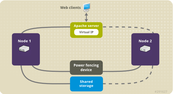
This use case requires that your system include the following components:
- A two-node Red Hat High Availability cluster with power fencing configured for each node. We recommend but do not require a private network. This procedure uses the cluster example provided in Creating a Red Hat High-Availability cluster with Pacemaker.
- A public virtual IP address, required for Apache.
- Shared storage for the nodes in the cluster, using iSCSI, Fibre Channel, or other shared network block device.
The cluster is configured with an Apache resource group, which contains the cluster components that the web server requires: an LVM resource, a file system resource, an IP address resource, and a web server resource. This resource group can fail over from one node of the cluster to the other, allowing either node to run the web server. Before creating the resource group for this cluster, you will be performing the following procedures:
-
Configure an XFS file system on the logical volume
my_lv. - Configure a web server.
After performing these steps, you create the resource group and the resources it contains.
49.1. Configuring an LVM volume with an XFS file system in a Pacemaker cluster
Create an LVM logical volume on storage that is shared between the nodes of the cluster with the following procedure.
LVM volumes and the corresponding partitions and devices used by cluster nodes must be connected to the cluster nodes only.
The following procedure creates an LVM logical volume and then creates an XFS file system on that volume for use in a Pacemaker cluster. In this example, the shared partition /dev/sdb1 is used to store the LVM physical volume from which the LVM logical volume will be created.
Procedure
On both nodes of the cluster, perform the following steps to set the value for the LVM system ID to the value of the
unameidentifier for the system. The LVM system ID will be used to ensure that only the cluster is capable of activating the volume group.Set the
system_id_sourceconfiguration option in the/etc/lvm/lvm.confconfiguration file touname.# Configuration option global/system_id_source. system_id_source = "uname"Verify that the LVM system ID on the node matches the
unamefor the node.# lvm systemid system ID: z1.example.com # uname -n z1.example.com
Create the LVM volume and create an XFS file system on that volume. Since the
/dev/sdb1partition is storage that is shared, you perform this part of the procedure on one node only.[root@z1 ~]# pvcreate /dev/sdb1 Physical volume "/dev/sdb1" successfully createdNoteIf your LVM volume group contains one or more physical volumes that reside on remote block storage, such as an iSCSI target, Red Hat recommends that you ensure that the service starts before Pacemaker starts. For information about configuring startup order for a remote physical volume used by a Pacemaker cluster, see Configuring startup order for resource dependencies not managed by Pacemaker.
Create the volume group
my_vgthat consists of the physical volume/dev/sdb1.For RHEL 8.5 and later, specify the
--setautoactivation nflag to ensure that volume groups managed by Pacemaker in a cluster will not be automatically activated on startup. If you are using an existing volume group for the LVM volume you are creating, you can reset this flag with thevgchange --setautoactivation ncommand for the volume group.[root@z1 ~]# vgcreate --setautoactivation n my_vg /dev/sdb1 Volume group "my_vg" successfully createdFor RHEL 8.4 and earlier, create the volume group with the following command.
[root@z1 ~]# vgcreate my_vg /dev/sdb1 Volume group "my_vg" successfully createdFor information about ensuring that volume groups managed by Pacemaker in a cluster will not be automatically activated on startup for RHEL 8.4 and earlier, see Ensuring a volume group is not activated on multiple cluster nodes.
Verify that the new volume group has the system ID of the node on which you are running and from which you created the volume group.
[root@z1 ~]# vgs -o+systemid VG #PV #LV #SN Attr VSize VFree System ID my_vg 1 0 0 wz--n- <1.82t <1.82t z1.example.comCreate a logical volume using the volume group
my_vg.[root@z1 ~]# lvcreate -L450 -n my_lv my_vg Rounding up size to full physical extent 452.00 MiB Logical volume "my_lv" createdYou can use the
lvscommand to display the logical volume.[root@z1 ~]# lvs LV VG Attr LSize Pool Origin Data% Move Log Copy% Convert my_lv my_vg -wi-a---- 452.00m ...Create an XFS file system on the logical volume
my_lv.[root@z1 ~]# mkfs.xfs /dev/my_vg/my_lv meta-data=/dev/my_vg/my_lv isize=512 agcount=4, agsize=28928 blks = sectsz=512 attr=2, projid32bit=1 ...
(RHEL 8.5 and later) If you have enabled the use of a devices file by setting
use_devicesfile = 1in thelvm.conffile, add the shared device to the devices file on the second node in the cluster. By default, the use of a devices file is not enabled.[root@z2 ~]# lvmdevices --adddev /dev/sdb1
49.2. Ensuring a volume group is not activated on multiple cluster nodes (RHEL 8.4 and earlier)
You can ensure that volume groups that are managed by Pacemaker in a cluster will not be automatically activated on startup with the following procedure. If a volume group is automatically activated on startup rather than by Pacemaker, there is a risk that the volume group will be active on multiple nodes at the same time, which could corrupt the volume group’s metadata.
For RHEL 8.5 and later, you can disable autoactivation for a volume group when you create the volume group by specifying the --setautoactivation n flag for the vgcreate command, as described in Configuring an LVM volume with an XFS file system in a Pacemaker cluster.
This procedure modifies the auto_activation_volume_list entry in the /etc/lvm/lvm.conf configuration file. The auto_activation_volume_list entry is used to limit autoactivation to specific logical volumes. Setting auto_activation_volume_list to an empty list disables autoactivation entirely.
Any local volumes that are not shared and are not managed by Pacemaker should be included in the auto_activation_volume_list entry, including volume groups related to the node’s local root and home directories. All volume groups managed by the cluster manager must be excluded from the auto_activation_volume_list entry.
Procedure
Perform the following procedure on each node in the cluster.
Determine which volume groups are currently configured on your local storage with the following command. This will output a list of the currently-configured volume groups. If you have space allocated in separate volume groups for root and for your home directory on this node, you will see those volumes in the output, as in this example.
# vgs --noheadings -o vg_name my_vg rhel_home rhel_rootAdd the volume groups other than
my_vg(the volume group you have just defined for the cluster) as entries toauto_activation_volume_listin the/etc/lvm/lvm.confconfiguration file.For example, if you have space allocated in separate volume groups for root and for your home directory, you would uncomment the
auto_activation_volume_listline of thelvm.conffile and add these volume groups as entries toauto_activation_volume_listas follows. Note that the volume group you have just defined for the cluster (my_vgin this example) is not in this list.auto_activation_volume_list = [ "rhel_root", "rhel_home" ]NoteIf no local volume groups are present on a node to be activated outside of the cluster manager, you must still initialize the
auto_activation_volume_listentry asauto_activation_volume_list = [].Rebuild the
initramfsboot image to guarantee that the boot image will not try to activate a volume group controlled by the cluster. Update theinitramfsdevice with the following command. This command may take up to a minute to complete.# dracut -H -f /boot/initramfs-$(uname -r).img $(uname -r)Reboot the node.
NoteIf you have installed a new Linux kernel since booting the node on which you created the boot image, the new
initrdimage will be for the kernel that was running when you created it and not for the new kernel that is running when you reboot the node. You can ensure that the correctinitrddevice is in use by running theuname -rcommand before and after the reboot to determine the kernel release that is running. If the releases are not the same, update theinitrdfile after rebooting with the new kernel and then reboot the node.When the node has rebooted, check whether the cluster services have started up again on that node by executing the
pcs cluster statuscommand on that node. If this yields the messageError: cluster is not currently running on this nodethen enter the following command.# pcs cluster startAlternately, you can wait until you have rebooted each node in the cluster and start cluster services on all of the nodes in the cluster with the following command.
# pcs cluster start --all
49.3. Configuring an Apache HTTP Server
Configure an Apache HTTP Server with the following procedure.
Procedure
Ensure that the Apache HTTP Server is installed on each node in the cluster. You also need the
wgettool installed on the cluster to be able to check the status of the Apache HTTP Server.On each node, execute the following command.
# yum install -y httpd wgetIf you are running the
firewallddaemon, on each node in the cluster enable the ports that are required by the Red Hat High Availability Add-On and enable the ports you will require for runninghttpd. This example enables thehttpdports for public access, but the specific ports to enable forhttpdmay vary for production use.# firewall-cmd --permanent --add-service=http # firewall-cmd --permanent --zone=public --add-service=http # firewall-cmd --reloadIn order for the Apache resource agent to get the status of Apache, on each node in the cluster create the following addition to the existing configuration to enable the status server URL.
# cat <<-END > /etc/httpd/conf.d/status.conf <Location /server-status> SetHandler server-status Require local </Location> ENDCreate a web page for Apache to serve up.
On one node in the cluster, ensure that the logical volume you created in Configuring an LVM volume with an XFS file system is activated, mount the file system that you created on that logical volume, create the file
index.htmlon that file system, and then unmount the file system.# lvchange -ay my_vg/my_lv # mount /dev/my_vg/my_lv /var/www/ # mkdir /var/www/html # mkdir /var/www/cgi-bin # mkdir /var/www/error # restorecon -R /var/www # cat <<-END >/var/www/html/index.html <html> <body>Hello</body> </html> END # umount /var/www
49.4. Creating the resources and resource groups
Create the resources for your cluster with the following procedure. To ensure these resources all run on the same node, they are configured as part of the resource group apachegroup. The resources to create are as follows, listed in the order in which they will start.
-
An
LVM-activateresource namedmy_lvmthat uses the LVM volume group you created in Configuring an LVM volume with an XFS file system. -
A
Filesystemresource namedmy_fs, that uses the file system device/dev/my_vg/my_lvyou created in Configuring an LVM volume with an XFS file system. -
An
IPaddr2resource, which is a floating IP address for theapachegroupresource group. The IP address must not be one already associated with a physical node. If theIPaddr2resource’s NIC device is not specified, the floating IP must reside on the same network as one of the node’s statically assigned IP addresses, otherwise the NIC device to assign the floating IP address cannot be properly detected. -
An
apacheresource namedWebsitethat uses theindex.htmlfile and the Apache configuration you defined in Configuring an Apache HTTP server.
The following procedure creates the resource group apachegroup and the resources that the group contains. The resources will start in the order in which you add them to the group, and they will stop in the reverse order in which they are added to the group. Run this procedure from one node of the cluster only.
Procedure
The following command creates the
LVM-activateresourcemy_lvm. Because the resource groupapachegroupdoes not yet exist, this command creates the resource group.NoteDo not configure more than one
LVM-activateresource that uses the same LVM volume group in an active/passive HA configuration, as this could cause data corruption. Additionally, do not configure anLVM-activateresource as a clone resource in an active/passive HA configuration.[root@z1 ~]# pcs resource create my_lvm ocf:heartbeat:LVM-activate vgname=my_vg vg_access_mode=system_id --group apachegroupWhen you create a resource, the resource is started automatically. You can use the following command to confirm that the resource was created and has started.
# pcs resource status Resource Group: apachegroup my_lvm (ocf::heartbeat:LVM-activate): StartedYou can manually stop and start an individual resource with the
pcs resource disableandpcs resource enablecommands.The following commands create the remaining resources for the configuration, adding them to the existing resource group
apachegroup.[root@z1 ~]# pcs resource create my_fs Filesystem device="/dev/my_vg/my_lv" directory="/var/www" fstype="xfs" --group apachegroup [root@z1 ~]# pcs resource create VirtualIP IPaddr2 ip=198.51.100.3 cidr_netmask=24 --group apachegroup [root@z1 ~]# pcs resource create Website apache configfile="/etc/httpd/conf/httpd.conf" statusurl="http://127.0.0.1/server-status" --group apachegroupAfter creating the resources and the resource group that contains them, you can check the status of the cluster. Note that all four resources are running on the same node.
[root@z1 ~]# pcs status Cluster name: my_cluster Last updated: Wed Jul 31 16:38:51 2013 Last change: Wed Jul 31 16:42:14 2013 via crm_attribute on z1.example.com Stack: corosync Current DC: z2.example.com (2) - partition with quorum Version: 1.1.10-5.el7-9abe687 2 Nodes configured 6 Resources configured Online: [ z1.example.com z2.example.com ] Full list of resources: myapc (stonith:fence_apc_snmp): Started z1.example.com Resource Group: apachegroup my_lvm (ocf::heartbeat:LVM-activate): Started z1.example.com my_fs (ocf::heartbeat:Filesystem): Started z1.example.com VirtualIP (ocf::heartbeat:IPaddr2): Started z1.example.com Website (ocf::heartbeat:apache): Started z1.example.comNote that if you have not configured a fencing device for your cluster, by default the resources do not start.
Once the cluster is up and running, you can point a browser to the IP address you defined as the
IPaddr2resource to view the sample display, consisting of the simple word "Hello".HelloIf you find that the resources you configured are not running, you can run the
pcs resource debug-start resourcecommand to test the resource configuration.When you use the
apacheresource agent to manage Apache, it does not usesystemd. Because of this, you must edit thelogrotatescript supplied with Apache so that it does not usesystemctlto reload Apache.Remove the following line in the
/etc/logrotate.d/httpdfile on each node in the cluster./bin/systemctl reload httpd.service > /dev/null 2>/dev/null || trueFor RHEL 8.6 and later, replace the line you removed with the following three lines, specifying
/var/run/httpd-website.pidas the PID file path where website is the name of the Apache resource. In this example, the Apache resource name isWebsite./usr/bin/test -f /var/run/httpd-Website.pid >/dev/null 2>/dev/null && /usr/bin/ps -q $(/usr/bin/cat /var/run/httpd-Website.pid) >/dev/null 2>/dev/null && /usr/sbin/httpd -f /etc/httpd/conf/httpd.conf -c "PidFile /var/run/httpd-Website.pid" -k graceful > /dev/null 2>/dev/null || trueFor RHEL 8.5 and earlier, replace the line you removed with the following three lines.
/usr/bin/test -f /run/httpd.pid >/dev/null 2>/dev/null && /usr/bin/ps -q $(/usr/bin/cat /run/httpd.pid) >/dev/null 2>/dev/null && /usr/sbin/httpd -f /etc/httpd/conf/httpd.conf -c "PidFile /run/httpd.pid" -k graceful > /dev/null 2>/dev/null || true
49.5. Testing the resource configuration
Test the resource configuration in a cluster with the following procedure.
In the cluster status display shown in Creating the resources and resource groups, all of the resources are running on node z1.example.com. You can test whether the resource group fails over to node z2.example.com by using the following procedure to put the first node in standby mode, after which the node will no longer be able to host resources.
Procedure
The following command puts node
z1.example.cominstandbymode.[root@z1 ~]# pcs node standby z1.example.comAfter putting node
z1instandbymode, check the cluster status. Note that the resources should now all be running onz2.[root@z1 ~]# pcs status Cluster name: my_cluster Last updated: Wed Jul 31 17:16:17 2013 Last change: Wed Jul 31 17:18:34 2013 via crm_attribute on z1.example.com Stack: corosync Current DC: z2.example.com (2) - partition with quorum Version: 1.1.10-5.el7-9abe687 2 Nodes configured 6 Resources configured Node z1.example.com (1): standby Online: [ z2.example.com ] Full list of resources: myapc (stonith:fence_apc_snmp): Started z1.example.com Resource Group: apachegroup my_lvm (ocf::heartbeat:LVM-activate): Started z2.example.com my_fs (ocf::heartbeat:Filesystem): Started z2.example.com VirtualIP (ocf::heartbeat:IPaddr2): Started z2.example.com Website (ocf::heartbeat:apache): Started z2.example.comThe web site at the defined IP address should still display, without interruption.
To remove
z1fromstandbymode, enter the following command.[root@z1 ~]# pcs node unstandby z1.example.comNoteRemoving a node from
standbymode does not in itself cause the resources to fail back over to that node. This will depend on theresource-stickinessvalue for the resources. For information about theresource-stickinessmeta attribute, see Configuring a resource to prefer its current node.
Chapter 50. Configuring an active/passive NFS server in a Red Hat High Availability cluster
The Red Hat High Availability Add-On provides support for running a highly available active/passive NFS server on a Red Hat Enterprise Linux High Availability Add-On cluster using shared storage. In the following example, you are configuring a two-node cluster in which clients access the NFS file system through a floating IP address. The NFS server runs on one of the two nodes in the cluster. If the node on which the NFS server is running becomes inoperative, the NFS server starts up again on the second node of the cluster with minimal service interruption.
This use case requires that your system include the following components:
- A two-node Red Hat High Availability cluster with power fencing configured for each node. We recommend but do not require a private network. This procedure uses the cluster example provided in Creating a Red Hat High-Availability cluster with Pacemaker.
- A public virtual IP address, required for the NFS server.
- Shared storage for the nodes in the cluster, using iSCSI, Fibre Channel, or other shared network block device.
Configuring a highly available active/passive NFS server on an existing two-node Red Hat Enterprise Linux High Availability cluster requires that you perform the following steps:
- Configure a file system on an LVM logical volume on the shared storage for the nodes in the cluster.
- Configure an NFS share on the shared storage on the LVM logical volume.
- Create the cluster resources.
- Test the NFS server you have configured.
50.1. Configuring an LVM volume with an XFS file system in a Pacemaker cluster
Create an LVM logical volume on storage that is shared between the nodes of the cluster with the following procedure.
LVM volumes and the corresponding partitions and devices used by cluster nodes must be connected to the cluster nodes only.
The following procedure creates an LVM logical volume and then creates an XFS file system on that volume for use in a Pacemaker cluster. In this example, the shared partition /dev/sdb1 is used to store the LVM physical volume from which the LVM logical volume will be created.
Procedure
On both nodes of the cluster, perform the following steps to set the value for the LVM system ID to the value of the
unameidentifier for the system. The LVM system ID will be used to ensure that only the cluster is capable of activating the volume group.Set the
system_id_sourceconfiguration option in the/etc/lvm/lvm.confconfiguration file touname.# Configuration option global/system_id_source. system_id_source = "uname"Verify that the LVM system ID on the node matches the
unamefor the node.# lvm systemid system ID: z1.example.com # uname -n z1.example.com
Create the LVM volume and create an XFS file system on that volume. Since the
/dev/sdb1partition is storage that is shared, you perform this part of the procedure on one node only.[root@z1 ~]# pvcreate /dev/sdb1 Physical volume "/dev/sdb1" successfully createdNoteIf your LVM volume group contains one or more physical volumes that reside on remote block storage, such as an iSCSI target, Red Hat recommends that you ensure that the service starts before Pacemaker starts. For information about configuring startup order for a remote physical volume used by a Pacemaker cluster, see Configuring startup order for resource dependencies not managed by Pacemaker.
Create the volume group
my_vgthat consists of the physical volume/dev/sdb1.For RHEL 8.5 and later, specify the
--setautoactivation nflag to ensure that volume groups managed by Pacemaker in a cluster will not be automatically activated on startup. If you are using an existing volume group for the LVM volume you are creating, you can reset this flag with thevgchange --setautoactivation ncommand for the volume group.[root@z1 ~]# vgcreate --setautoactivation n my_vg /dev/sdb1 Volume group "my_vg" successfully createdFor RHEL 8.4 and earlier, create the volume group with the following command.
[root@z1 ~]# vgcreate my_vg /dev/sdb1 Volume group "my_vg" successfully createdFor information about ensuring that volume groups managed by Pacemaker in a cluster will not be automatically activated on startup for RHEL 8.4 and earlier, see Ensuring a volume group is not activated on multiple cluster nodes.
Verify that the new volume group has the system ID of the node on which you are running and from which you created the volume group.
[root@z1 ~]# vgs -o+systemid VG #PV #LV #SN Attr VSize VFree System ID my_vg 1 0 0 wz--n- <1.82t <1.82t z1.example.comCreate a logical volume using the volume group
my_vg.[root@z1 ~]# lvcreate -L450 -n my_lv my_vg Rounding up size to full physical extent 452.00 MiB Logical volume "my_lv" createdYou can use the
lvscommand to display the logical volume.[root@z1 ~]# lvs LV VG Attr LSize Pool Origin Data% Move Log Copy% Convert my_lv my_vg -wi-a---- 452.00m ...Create an XFS file system on the logical volume
my_lv.[root@z1 ~]# mkfs.xfs /dev/my_vg/my_lv meta-data=/dev/my_vg/my_lv isize=512 agcount=4, agsize=28928 blks = sectsz=512 attr=2, projid32bit=1 ...
(RHEL 8.5 and later) If you have enabled the use of a devices file by setting
use_devicesfile = 1in thelvm.conffile, add the shared device to the devices file on the second node in the cluster. By default, the use of a devices file is not enabled.[root@z2 ~]# lvmdevices --adddev /dev/sdb1
50.2. Ensuring a volume group is not activated on multiple cluster nodes (RHEL 8.4 and earlier)
You can ensure that volume groups that are managed by Pacemaker in a cluster will not be automatically activated on startup with the following procedure. If a volume group is automatically activated on startup rather than by Pacemaker, there is a risk that the volume group will be active on multiple nodes at the same time, which could corrupt the volume group’s metadata.
For RHEL 8.5 and later, you can disable autoactivation for a volume group when you create the volume group by specifying the --setautoactivation n flag for the vgcreate command, as described in Configuring an LVM volume with an XFS file system in a Pacemaker cluster.
This procedure modifies the auto_activation_volume_list entry in the /etc/lvm/lvm.conf configuration file. The auto_activation_volume_list entry is used to limit autoactivation to specific logical volumes. Setting auto_activation_volume_list to an empty list disables autoactivation entirely.
Any local volumes that are not shared and are not managed by Pacemaker should be included in the auto_activation_volume_list entry, including volume groups related to the node’s local root and home directories. All volume groups managed by the cluster manager must be excluded from the auto_activation_volume_list entry.
Procedure
Perform the following procedure on each node in the cluster.
Determine which volume groups are currently configured on your local storage with the following command. This will output a list of the currently-configured volume groups. If you have space allocated in separate volume groups for root and for your home directory on this node, you will see those volumes in the output, as in this example.
# vgs --noheadings -o vg_name my_vg rhel_home rhel_rootAdd the volume groups other than
my_vg(the volume group you have just defined for the cluster) as entries toauto_activation_volume_listin the/etc/lvm/lvm.confconfiguration file.For example, if you have space allocated in separate volume groups for root and for your home directory, you would uncomment the
auto_activation_volume_listline of thelvm.conffile and add these volume groups as entries toauto_activation_volume_listas follows. Note that the volume group you have just defined for the cluster (my_vgin this example) is not in this list.auto_activation_volume_list = [ "rhel_root", "rhel_home" ]NoteIf no local volume groups are present on a node to be activated outside of the cluster manager, you must still initialize the
auto_activation_volume_listentry asauto_activation_volume_list = [].Rebuild the
initramfsboot image to guarantee that the boot image will not try to activate a volume group controlled by the cluster. Update theinitramfsdevice with the following command. This command may take up to a minute to complete.# dracut -H -f /boot/initramfs-$(uname -r).img $(uname -r)Reboot the node.
NoteIf you have installed a new Linux kernel since booting the node on which you created the boot image, the new
initrdimage will be for the kernel that was running when you created it and not for the new kernel that is running when you reboot the node. You can ensure that the correctinitrddevice is in use by running theuname -rcommand before and after the reboot to determine the kernel release that is running. If the releases are not the same, update theinitrdfile after rebooting with the new kernel and then reboot the node.When the node has rebooted, check whether the cluster services have started up again on that node by executing the
pcs cluster statuscommand on that node. If this yields the messageError: cluster is not currently running on this nodethen enter the following command.# pcs cluster startAlternately, you can wait until you have rebooted each node in the cluster and start cluster services on all of the nodes in the cluster with the following command.
# pcs cluster start --all
50.4. Configuring the resources and resource group for an NFS server in a cluster
Configure the cluster resources for an NFS server in a cluster with the following procedure.
If you have not configured a fencing device for your cluster, by default the resources do not start.
If you find that the resources you configured are not running, you can run the pcs resource debug-start resource command to test the resource configuration. This starts the service outside of the cluster’s control and knowledge. At the point the configured resources are running again, run pcs resource cleanup resource to make the cluster aware of the updates.
Procedure
The following procedure configures the system resources. To ensure these resources all run on the same node, they are configured as part of the resource group nfsgroup. The resources will start in the order in which you add them to the group, and they will stop in the reverse order in which they are added to the group. Run this procedure from one node of the cluster only.
Create the LVM-activate resource named
my_lvm. Because the resource groupnfsgroupdoes not yet exist, this command creates the resource group.WarningDo not configure more than one
LVM-activateresource that uses the same LVM volume group in an active/passive HA configuration, as this risks data corruption. Additionally, do not configure anLVM-activateresource as a clone resource in an active/passive HA configuration.[root@z1 ~]# pcs resource create my_lvm ocf:heartbeat:LVM-activate vgname=my_vg vg_access_mode=system_id --group nfsgroupCheck the status of the cluster to verify that the resource is running.
root@z1 ~]# pcs status Cluster name: my_cluster Last updated: Thu Jan 8 11:13:17 2015 Last change: Thu Jan 8 11:13:08 2015 Stack: corosync Current DC: z2.example.com (2) - partition with quorum Version: 1.1.12-a14efad 2 Nodes configured 3 Resources configured Online: [ z1.example.com z2.example.com ] Full list of resources: myapc (stonith:fence_apc_snmp): Started z1.example.com Resource Group: nfsgroup my_lvm (ocf::heartbeat:LVM-activate): Started z1.example.com PCSD Status: z1.example.com: Online z2.example.com: Online Daemon Status: corosync: active/enabled pacemaker: active/enabled pcsd: active/enabledConfigure a
Filesystemresource for the cluster.The following command configures an XFS
Filesystemresource namednfsshareas part of thenfsgroupresource group. This file system uses the LVM volume group and XFS file system you created in Configuring an LVM volume with an XFS file system and will be mounted on the/nfssharedirectory you created in Configuring an NFS share.[root@z1 ~]# pcs resource create nfsshare Filesystem device=/dev/my_vg/my_lv directory=/nfsshare fstype=xfs --group nfsgroupYou can specify mount options as part of the resource configuration for a
Filesystemresource with theoptions=optionsparameter. Run thepcs resource describe Filesystemcommand for full configuration options.Verify that the
my_lvmandnfsshareresources are running.[root@z1 ~]# pcs status ... Full list of resources: myapc (stonith:fence_apc_snmp): Started z1.example.com Resource Group: nfsgroup my_lvm (ocf::heartbeat:LVM-activate): Started z1.example.com nfsshare (ocf::heartbeat:Filesystem): Started z1.example.com ...Create the
nfsserverresource namednfs-daemonas part of the resource groupnfsgroup.NoteThe
nfsserverresource allows you to specify annfs_shared_infodirparameter, which is a directory that NFS servers use to store NFS-related stateful information.It is recommended that this attribute be set to a subdirectory of one of the
Filesystemresources you created in this collection of exports. This ensures that the NFS servers are storing their stateful information on a device that will become available to another node if this resource group needs to relocate. In this example;-
/nfsshareis the shared-storage directory managed by theFilesystemresource -
/nfsshare/exports/export1and/nfsshare/exports/export2are the export directories -
/nfsshare/nfsinfois the shared-information directory for thenfsserverresource
[root@z1 ~]# pcs resource create nfs-daemon nfsserver nfs_shared_infodir=/nfsshare/nfsinfo nfs_no_notify=true --group nfsgroup [root@z1 ~]# pcs status ...-
Add the
exportfsresources to export the/nfsshare/exportsdirectory. These resources are part of the resource groupnfsgroup. This builds a virtual directory for NFSv4 clients. NFSv3 clients can access these exports as well.NoteThe
fsid=0option is required only if you want to create a virtual directory for NFSv4 clients. For more information, see the Red Hat Knowledgebase solution How do I configure the fsid option in an NFS server’s /etc/exports file?.[root@z1 ~]# pcs resource create nfs-root exportfs clientspec=192.168.122.0/255.255.255.0 options=rw,sync,no_root_squash directory=/nfsshare/exports fsid=0 --group nfsgroup [root@z1 ~]# pcs resource create nfs-export1 exportfs clientspec=192.168.122.0/255.255.255.0 options=rw,sync,no_root_squash directory=/nfsshare/exports/export1 fsid=1 --group nfsgroup [root@z1 ~]# pcs resource create nfs-export2 exportfs clientspec=192.168.122.0/255.255.255.0 options=rw,sync,no_root_squash directory=/nfsshare/exports/export2 fsid=2 --group nfsgroupAdd the floating IP address resource that NFS clients will use to access the NFS share. This resource is part of the resource group
nfsgroup. For this example deployment, we are using 192.168.122.200 as the floating IP address.[root@z1 ~]# pcs resource create nfs_ip IPaddr2 ip=192.168.122.200 cidr_netmask=24 --group nfsgroupAdd an
nfsnotifyresource for sending NFSv3 reboot notifications once the entire NFS deployment has initialized. This resource is part of the resource groupnfsgroup.NoteFor the NFS notification to be processed correctly, the floating IP address must have a host name associated with it that is consistent on both the NFS servers and the NFS client.
[root@z1 ~]# pcs resource create nfs-notify nfsnotify source_host=192.168.122.200 --group nfsgroupAfter creating the resources and the resource constraints, you can check the status of the cluster. Note that all resources are running on the same node.
[root@z1 ~]# pcs status ... Full list of resources: myapc (stonith:fence_apc_snmp): Started z1.example.com Resource Group: nfsgroup my_lvm (ocf::heartbeat:LVM-activate): Started z1.example.com nfsshare (ocf::heartbeat:Filesystem): Started z1.example.com nfs-daemon (ocf::heartbeat:nfsserver): Started z1.example.com nfs-root (ocf::heartbeat:exportfs): Started z1.example.com nfs-export1 (ocf::heartbeat:exportfs): Started z1.example.com nfs-export2 (ocf::heartbeat:exportfs): Started z1.example.com nfs_ip (ocf::heartbeat:IPaddr2): Started z1.example.com nfs-notify (ocf::heartbeat:nfsnotify): Started z1.example.com ...
50.5. Testing the NFS resource configuration
You can validate your NFS resource configuration in a high availability cluster with the following procedures. You should be able to mount the exported file system with either NFSv3 or NFSv4.
50.5.1. Testing the NFS export
-
If you are running the
firewallddaemon on your cluster nodes, ensure that the ports that your system requires for NFS access are enabled on all nodes. On a node outside of the cluster, residing in the same network as the deployment, verify that the NFS share can be seen by mounting the NFS share. For this example, we are using the 192.168.122.0/24 network.
# showmount -e 192.168.122.200 Export list for 192.168.122.200: /nfsshare/exports/export1 192.168.122.0/255.255.255.0 /nfsshare/exports 192.168.122.0/255.255.255.0 /nfsshare/exports/export2 192.168.122.0/255.255.255.0To verify that you can mount the NFS share with NFSv4, mount the NFS share to a directory on the client node. After mounting, verify that the contents of the export directories are visible. Unmount the share after testing.
# mkdir nfsshare # mount -o "vers=4" 192.168.122.200:export1 nfsshare # ls nfsshare clientdatafile1 # umount nfsshareVerify that you can mount the NFS share with NFSv3. After mounting, verify that the test file
clientdatafile1is visible. Unlike NFSv4, since NFSv3 does not use the virtual file system, you must mount a specific export. Unmount the share after testing.# mkdir nfsshare # mount -o "vers=3" 192.168.122.200:/nfsshare/exports/export2 nfsshare # ls nfsshare clientdatafile2 # umount nfsshare
50.5.2. Testing for failover
On a node outside of the cluster, mount the NFS share and verify access to the
clientdatafile1file you created in Configuring an NFS share.# mkdir nfsshare # mount -o "vers=4" 192.168.122.200:export1 nfsshare # ls nfsshare clientdatafile1From a node within the cluster, determine which node in the cluster is running
nfsgroup. In this example,nfsgroupis running onz1.example.com.[root@z1 ~]# pcs status ... Full list of resources: myapc (stonith:fence_apc_snmp): Started z1.example.com Resource Group: nfsgroup my_lvm (ocf::heartbeat:LVM-activate): Started z1.example.com nfsshare (ocf::heartbeat:Filesystem): Started z1.example.com nfs-daemon (ocf::heartbeat:nfsserver): Started z1.example.com nfs-root (ocf::heartbeat:exportfs): Started z1.example.com nfs-export1 (ocf::heartbeat:exportfs): Started z1.example.com nfs-export2 (ocf::heartbeat:exportfs): Started z1.example.com nfs_ip (ocf::heartbeat:IPaddr2): Started z1.example.com nfs-notify (ocf::heartbeat:nfsnotify): Started z1.example.com ...From a node within the cluster, put the node that is running
nfsgroupin standby mode.[root@z1 ~]# pcs node standby z1.example.comVerify that
nfsgroupsuccessfully starts on the other cluster node.[root@z1 ~]# pcs status ... Full list of resources: Resource Group: nfsgroup my_lvm (ocf::heartbeat:LVM-activate): Started z2.example.com nfsshare (ocf::heartbeat:Filesystem): Started z2.example.com nfs-daemon (ocf::heartbeat:nfsserver): Started z2.example.com nfs-root (ocf::heartbeat:exportfs): Started z2.example.com nfs-export1 (ocf::heartbeat:exportfs): Started z2.example.com nfs-export2 (ocf::heartbeat:exportfs): Started z2.example.com nfs_ip (ocf::heartbeat:IPaddr2): Started z2.example.com nfs-notify (ocf::heartbeat:nfsnotify): Started z2.example.com ...From the node outside the cluster on which you have mounted the NFS share, verify that this outside node still continues to have access to the test file within the NFS mount.
# ls nfsshare clientdatafile1Service will be lost briefly for the client during the failover but the client should recover it with no user intervention. By default, clients using NFSv4 may take up to 90 seconds to recover the mount; this 90 seconds represents the NFSv4 file lease grace period observed by the server on startup. NFSv3 clients should recover access to the mount in a matter of a few seconds.
From a node within the cluster, remove the node that was initially running
nfsgroupfrom standby mode.NoteRemoving a node from
standbymode does not in itself cause the resources to fail back over to that node. This will depend on theresource-stickinessvalue for the resources. For information about theresource-stickinessmeta attribute, see Configuring a resource to prefer its current node.[root@z1 ~]# pcs node unstandby z1.example.com
Chapter 51. GFS2 file systems in a cluster
Use the following administrative procedures to configure GFS2 file systems in a Red Hat high availability cluster.
51.1. Configuring a GFS2 file system in a cluster
You can set up a Pacemaker cluster that includes GFS2 file systems with the following procedure. In this example, you create three GFS2 file systems on three logical volumes in a two-node cluster.
Prerequisites
- Install and start the cluster software on both cluster nodes and create a basic two-node cluster.
- Configure fencing for the cluster.
For information about creating a Pacemaker cluster and configuring fencing for the cluster, see Creating a Red Hat High-Availability cluster with Pacemaker.
Procedure
On both nodes in the cluster, enable the repository for Resilient Storage that corresponds to your system architecture. For example, to enable the Resilient Storage repository for an x86_64 system, you can enter the following
subscription-managercommand:# subscription-manager repos --enable=rhel-8-for-x86_64-resilientstorage-rpmsNote that the Resilient Storage repository is a superset of the High Availability repository. If you enable the Resilient Storage repository you do not also need to enable the High Availability repository.
On both nodes of the cluster, install the
lvm2-lockd,gfs2-utils, anddlmpackages. To support these packages, you must be subscribed to the AppStream channel and the Resilient Storage channel.# yum install lvm2-lockd gfs2-utils dlmOn both nodes of the cluster, set the
use_lvmlockdconfiguration option in the/etc/lvm/lvm.conffile touse_lvmlockd=1.... use_lvmlockd = 1 ...Set the global Pacemaker parameter
no-quorum-policytofreeze.NoteBy default, the value of
no-quorum-policyis set tostop, indicating that once quorum is lost, all the resources on the remaining partition will immediately be stopped. Typically this default is the safest and most optimal option, but unlike most resources, GFS2 requires quorum to function. When quorum is lost both the applications using the GFS2 mounts and the GFS2 mount itself cannot be correctly stopped. Any attempts to stop these resources without quorum will fail which will ultimately result in the entire cluster being fenced every time quorum is lost.To address this situation, set
no-quorum-policytofreezewhen GFS2 is in use. This means that when quorum is lost, the remaining partition will do nothing until quorum is regained.[root@z1 ~]# pcs property set no-quorum-policy=freezeSet up a
dlmresource. This is a required dependency for configuring a GFS2 file system in a cluster. This example creates thedlmresource as part of a resource group namedlocking.[root@z1 ~]# pcs resource create dlm --group locking ocf:pacemaker:controld op monitor interval=30s on-fail=fenceClone the
lockingresource group so that the resource group can be active on both nodes of the cluster.[root@z1 ~]# pcs resource clone locking interleave=trueSet up an
lvmlockdresource as part of thelockingresource group.[root@z1 ~]# pcs resource create lvmlockd --group locking ocf:heartbeat:lvmlockd op monitor interval=30s on-fail=fenceCheck the status of the cluster to ensure that the
lockingresource group has started on both nodes of the cluster.[root@z1 ~]# pcs status --full Cluster name: my_cluster [...] Online: [ z1.example.com (1) z2.example.com (2) ] Full list of resources: smoke-apc (stonith:fence_apc): Started z1.example.com Clone Set: locking-clone [locking] Resource Group: locking:0 dlm (ocf::pacemaker:controld): Started z1.example.com lvmlockd (ocf::heartbeat:lvmlockd): Started z1.example.com Resource Group: locking:1 dlm (ocf::pacemaker:controld): Started z2.example.com lvmlockd (ocf::heartbeat:lvmlockd): Started z2.example.com Started: [ z1.example.com z2.example.com ]On one node of the cluster, create two shared volume groups. One volume group will contain two GFS2 file systems, and the other volume group will contain one GFS2 file system.
NoteIf your LVM volume group contains one or more physical volumes that reside on remote block storage, such as an iSCSI target, Red Hat recommends that you ensure that the service starts before Pacemaker starts. For information about configuring startup order for a remote physical volume used by a Pacemaker cluster, see Configuring startup order for resource dependencies not managed by Pacemaker.
The following command creates the shared volume group
shared_vg1on/dev/vdb.[root@z1 ~]# vgcreate --shared shared_vg1 /dev/vdb Physical volume "/dev/vdb" successfully created. Volume group "shared_vg1" successfully created VG shared_vg1 starting dlm lockspace Starting locking. Waiting until locks are ready...The following command creates the shared volume group
shared_vg2on/dev/vdc.[root@z1 ~]# vgcreate --shared shared_vg2 /dev/vdc Physical volume "/dev/vdc" successfully created. Volume group "shared_vg2" successfully created VG shared_vg2 starting dlm lockspace Starting locking. Waiting until locks are ready...On the second node in the cluster:
(RHEL 8.5 and later) If you have enabled the use of a devices file by setting
use_devicesfile = 1in thelvm.conffile, add the shared devices to the devices file. By default, the use of a devices file is not enabled.[root@z2 ~]# lvmdevices --adddev /dev/vdb [root@z2 ~]# lvmdevices --adddev /dev/vdcStart the lock manager for each of the shared volume groups.
[root@z2 ~]# vgchange --lockstart shared_vg1 VG shared_vg1 starting dlm lockspace Starting locking. Waiting until locks are ready... [root@z2 ~]# vgchange --lockstart shared_vg2 VG shared_vg2 starting dlm lockspace Starting locking. Waiting until locks are ready...
On one node in the cluster, create the shared logical volumes and format the volumes with a GFS2 file system. One journal is required for each node that mounts the file system. Ensure that you create enough journals for each of the nodes in your cluster. The format of the lock table name is ClusterName:FSName where ClusterName is the name of the cluster for which the GFS2 file system is being created and FSName is the file system name, which must be unique for all
lock_dlmfile systems over the cluster.[root@z1 ~]# lvcreate --activate sy -L5G -n shared_lv1 shared_vg1 Logical volume "shared_lv1" created. [root@z1 ~]# lvcreate --activate sy -L5G -n shared_lv2 shared_vg1 Logical volume "shared_lv2" created. [root@z1 ~]# lvcreate --activate sy -L5G -n shared_lv1 shared_vg2 Logical volume "shared_lv1" created. [root@z1 ~]# mkfs.gfs2 -j2 -p lock_dlm -t my_cluster:gfs2-demo1 /dev/shared_vg1/shared_lv1 [root@z1 ~]# mkfs.gfs2 -j2 -p lock_dlm -t my_cluster:gfs2-demo2 /dev/shared_vg1/shared_lv2 [root@z1 ~]# mkfs.gfs2 -j2 -p lock_dlm -t my_cluster:gfs2-demo3 /dev/shared_vg2/shared_lv1Create an
LVM-activateresource for each logical volume to automatically activate that logical volume on all nodes.Create an
LVM-activateresource namedsharedlv1for the logical volumeshared_lv1in volume groupshared_vg1. This command also creates the resource groupshared_vg1that includes the resource. In this example, the resource group has the same name as the shared volume group that includes the logical volume.[root@z1 ~]# pcs resource create sharedlv1 --group shared_vg1 ocf:heartbeat:LVM-activate lvname=shared_lv1 vgname=shared_vg1 activation_mode=shared vg_access_mode=lvmlockdCreate an
LVM-activateresource namedsharedlv2for the logical volumeshared_lv2in volume groupshared_vg1. This resource will also be part of the resource groupshared_vg1.[root@z1 ~]# pcs resource create sharedlv2 --group shared_vg1 ocf:heartbeat:LVM-activate lvname=shared_lv2 vgname=shared_vg1 activation_mode=shared vg_access_mode=lvmlockdCreate an
LVM-activateresource namedsharedlv3for the logical volumeshared_lv1in volume groupshared_vg2. This command also creates the resource groupshared_vg2that includes the resource.[root@z1 ~]# pcs resource create sharedlv3 --group shared_vg2 ocf:heartbeat:LVM-activate lvname=shared_lv1 vgname=shared_vg2 activation_mode=shared vg_access_mode=lvmlockd
Clone the two new resource groups.
[root@z1 ~]# pcs resource clone shared_vg1 interleave=true [root@z1 ~]# pcs resource clone shared_vg2 interleave=trueConfigure ordering constraints to ensure that the
lockingresource group that includes thedlmandlvmlockdresources starts first.[root@z1 ~]# pcs constraint order start locking-clone then shared_vg1-clone Adding locking-clone shared_vg1-clone (kind: Mandatory) (Options: first-action=start then-action=start) [root@z1 ~]# pcs constraint order start locking-clone then shared_vg2-clone Adding locking-clone shared_vg2-clone (kind: Mandatory) (Options: first-action=start then-action=start)Configure colocation constraints to ensure that the
vg1andvg2resource groups start on the same node as thelockingresource group.[root@z1 ~]# pcs constraint colocation add shared_vg1-clone with locking-clone [root@z1 ~]# pcs constraint colocation add shared_vg2-clone with locking-cloneOn both nodes in the cluster, verify that the logical volumes are active. There may be a delay of a few seconds.
[root@z1 ~]# lvs LV VG Attr LSize shared_lv1 shared_vg1 -wi-a----- 5.00g shared_lv2 shared_vg1 -wi-a----- 5.00g shared_lv1 shared_vg2 -wi-a----- 5.00g [root@z2 ~]# lvs LV VG Attr LSize shared_lv1 shared_vg1 -wi-a----- 5.00g shared_lv2 shared_vg1 -wi-a----- 5.00g shared_lv1 shared_vg2 -wi-a----- 5.00gCreate a file system resource to automatically mount each GFS2 file system on all nodes.
You should not add the file system to the
/etc/fstabfile because it will be managed as a Pacemaker cluster resource. Mount options can be specified as part of the resource configuration withoptions=options. Run thepcs resource describe Filesystemcommand to display the full configuration options.The following commands create the file system resources. These commands add each resource to the resource group that includes the logical volume resource for that file system.
[root@z1 ~]# pcs resource create sharedfs1 --group shared_vg1 ocf:heartbeat:Filesystem device="/dev/shared_vg1/shared_lv1" directory="/mnt/gfs1" fstype="gfs2" options=noatime op monitor interval=10s on-fail=fence [root@z1 ~]# pcs resource create sharedfs2 --group shared_vg1 ocf:heartbeat:Filesystem device="/dev/shared_vg1/shared_lv2" directory="/mnt/gfs2" fstype="gfs2" options=noatime op monitor interval=10s on-fail=fence [root@z1 ~]# pcs resource create sharedfs3 --group shared_vg2 ocf:heartbeat:Filesystem device="/dev/shared_vg2/shared_lv1" directory="/mnt/gfs3" fstype="gfs2" options=noatime op monitor interval=10s on-fail=fence
Verification
Verify that the GFS2 file systems are mounted on both nodes of the cluster.
[root@z1 ~]# mount | grep gfs2 /dev/mapper/shared_vg1-shared_lv1 on /mnt/gfs1 type gfs2 (rw,noatime,seclabel) /dev/mapper/shared_vg1-shared_lv2 on /mnt/gfs2 type gfs2 (rw,noatime,seclabel) /dev/mapper/shared_vg2-shared_lv1 on /mnt/gfs3 type gfs2 (rw,noatime,seclabel) [root@z2 ~]# mount | grep gfs2 /dev/mapper/shared_vg1-shared_lv1 on /mnt/gfs1 type gfs2 (rw,noatime,seclabel) /dev/mapper/shared_vg1-shared_lv2 on /mnt/gfs2 type gfs2 (rw,noatime,seclabel) /dev/mapper/shared_vg2-shared_lv1 on /mnt/gfs3 type gfs2 (rw,noatime,seclabel)Check the status of the cluster.
[root@z1 ~]# pcs status --full Cluster name: my_cluster [...] Full list of resources: smoke-apc (stonith:fence_apc): Started z1.example.com Clone Set: locking-clone [locking] Resource Group: locking:0 dlm (ocf::pacemaker:controld): Started z2.example.com lvmlockd (ocf::heartbeat:lvmlockd): Started z2.example.com Resource Group: locking:1 dlm (ocf::pacemaker:controld): Started z1.example.com lvmlockd (ocf::heartbeat:lvmlockd): Started z1.example.com Started: [ z1.example.com z2.example.com ] Clone Set: shared_vg1-clone [shared_vg1] Resource Group: shared_vg1:0 sharedlv1 (ocf::heartbeat:LVM-activate): Started z2.example.com sharedlv2 (ocf::heartbeat:LVM-activate): Started z2.example.com sharedfs1 (ocf::heartbeat:Filesystem): Started z2.example.com sharedfs2 (ocf::heartbeat:Filesystem): Started z2.example.com Resource Group: shared_vg1:1 sharedlv1 (ocf::heartbeat:LVM-activate): Started z1.example.com sharedlv2 (ocf::heartbeat:LVM-activate): Started z1.example.com sharedfs1 (ocf::heartbeat:Filesystem): Started z1.example.com sharedfs2 (ocf::heartbeat:Filesystem): Started z1.example.com Started: [ z1.example.com z2.example.com ] Clone Set: shared_vg2-clone [shared_vg2] Resource Group: shared_vg2:0 sharedlv3 (ocf::heartbeat:LVM-activate): Started z2.example.com sharedfs3 (ocf::heartbeat:Filesystem): Started z2.example.com Resource Group: shared_vg2:1 sharedlv3 (ocf::heartbeat:LVM-activate): Started z1.example.com sharedfs3 (ocf::heartbeat:Filesystem): Started z1.example.com Started: [ z1.example.com z2.example.com ] ...
51.2. Configuring an encrypted GFS2 file system in a cluster
(RHEL 8.4 and later) You can create a Pacemaker cluster that includes a LUKS encrypted GFS2 file system with the following procedure. In this example, you create one GFS2 file systems on a logical volume and encrypt the file system. Encrypted GFS2 file systems are supported using the crypt resource agent, which provides support for LUKS encryption.
There are three parts to this procedure:
- Configuring a shared logical volume in a Pacemaker cluster
-
Encrypting the logical volume and creating a
cryptresource - Formatting the encrypted logical volume with a GFS2 file system and creating a file system resource for the cluster
51.2.2. Encrypt the logical volume and create a crypt resource
Prerequisites
- You have configured a shared logical volume in a Pacemaker cluster.
Procedure
On one node in the cluster, create a new file that will contain the crypt key and set the permissions on the file so that it is readable only by root.
[root@z1 ~]# touch /etc/crypt_keyfile [root@z1 ~]# chmod 600 /etc/crypt_keyfileCreate the crypt key.
[root@z1 ~]# dd if=/dev/urandom bs=4K count=1 of=/etc/crypt_keyfile 1+0 records in 1+0 records out 4096 bytes (4.1 kB, 4.0 KiB) copied, 0.000306202 s, 13.4 MB/s [root@z1 ~]# scp /etc/crypt_keyfile root@z2.example.com:/etc/Distribute the crypt keyfile to the other nodes in the cluster, using the
-pparameter to preserve the permissions you set.[root@z1 ~]# scp -p /etc/crypt_keyfile root@z2.example.com:/etc/Create the encrypted device on the LVM volume where you will configure the encrypted GFS2 file system.
[root@z1 ~]# cryptsetup luksFormat /dev/shared_vg1/shared_lv1 --type luks2 --key-file=/etc/crypt_keyfile WARNING! ======== This will overwrite data on /dev/shared_vg1/shared_lv1 irrevocably. Are you sure? (Type 'yes' in capital letters): YESCreate the crypt resource as part of the
shared_vg1volume group.[root@z1 ~]# pcs resource create crypt --group shared_vg1 ocf:heartbeat:crypt crypt_dev="luks_lv1" crypt_type=luks2 key_file=/etc/crypt_keyfile encrypted_dev="/dev/shared_vg1/shared_lv1"
Verification
Ensure that the crypt resource has created the crypt device, which in this example is /dev/mapper/luks_lv1.
[root@z1 ~]# ls -l /dev/mapper/
...
lrwxrwxrwx 1 root root 7 Mar 4 09:52 luks_lv1 -> ../dm-3
...51.2.3. Format the encrypted logical volume with a GFS2 file system and create a file system resource for the cluster
Prerequisites
- You have encrypted the logical volume and created a crypt resource.
Procedure
On one node in the cluster, format the volume with a GFS2 file system. One journal is required for each node that mounts the file system. Ensure that you create enough journals for each of the nodes in your cluster. The format of the lock table name is ClusterName:FSName where ClusterName is the name of the cluster for which the GFS2 file system is being created and FSName is the file system name, which must be unique for all
lock_dlmfile systems over the cluster.[root@z1 ~]# mkfs.gfs2 -j3 -p lock_dlm -t my_cluster:gfs2-demo1 /dev/mapper/luks_lv1 /dev/mapper/luks_lv1 is a symbolic link to /dev/dm-3 This will destroy any data on /dev/dm-3 Are you sure you want to proceed? [y/n] y Discarding device contents (may take a while on large devices): Done Adding journals: Done Building resource groups: Done Creating quota file: Done Writing superblock and syncing: Done Device: /dev/mapper/luks_lv1 Block size: 4096 Device size: 4.98 GB (1306624 blocks) Filesystem size: 4.98 GB (1306622 blocks) Journals: 3 Journal size: 16MB Resource groups: 23 Locking protocol: "lock_dlm" Lock table: "my_cluster:gfs2-demo1" UUID: de263f7b-0f12-4d02-bbb2-56642fade293Create a file system resource to automatically mount the GFS2 file system on all nodes.
Do not add the file system to the
/etc/fstabfile because it will be managed as a Pacemaker cluster resource. Mount options can be specified as part of the resource configuration withoptions=options. Run thepcs resource describe Filesystemcommand for full configuration options.The following command creates the file system resource. This command adds the resource to the resource group that includes the logical volume resource for that file system.
[root@z1 ~]# pcs resource create sharedfs1 --group shared_vg1 ocf:heartbeat:Filesystem device="/dev/mapper/luks_lv1" directory="/mnt/gfs1" fstype="gfs2" options=noatime op monitor interval=10s on-fail=fence
Verification
Verify that the GFS2 file system is mounted on both nodes of the cluster.
[root@z1 ~]# mount | grep gfs2 /dev/mapper/luks_lv1 on /mnt/gfs1 type gfs2 (rw,noatime,seclabel) [root@z2 ~]# mount | grep gfs2 /dev/mapper/luks_lv1 on /mnt/gfs1 type gfs2 (rw,noatime,seclabel)Check the status of the cluster.
[root@z1 ~]# pcs status --full Cluster name: my_cluster [...] Full list of resources: smoke-apc (stonith:fence_apc): Started z1.example.com Clone Set: locking-clone [locking] Resource Group: locking:0 dlm (ocf::pacemaker:controld): Started z2.example.com lvmlockd (ocf::heartbeat:lvmlockd): Started z2.example.com Resource Group: locking:1 dlm (ocf::pacemaker:controld): Started z1.example.com lvmlockd (ocf::heartbeat:lvmlockd): Started z1.example.com Started: [ z1.example.com z2.example.com ] Clone Set: shared_vg1-clone [shared_vg1] Resource Group: shared_vg1:0 sharedlv1 (ocf::heartbeat:LVM-activate): Started z2.example.com crypt (ocf::heartbeat:crypt) Started z2.example.com sharedfs1 (ocf::heartbeat:Filesystem): Started z2.example.com Resource Group: shared_vg1:1 sharedlv1 (ocf::heartbeat:LVM-activate): Started z1.example.com crypt (ocf::heartbeat:crypt) Started z1.example.com sharedfs1 (ocf::heartbeat:Filesystem): Started z1.example.com Started: [z1.example.com z2.example.com ] ...
51.3. Migrating a GFS2 file system from RHEL7 to RHEL8
You can use your existing Red Hat Enterprise 7 logical volumes when configuring a RHEL 8 cluster that includes GFS2 file systems.
In Red Hat Enterprise Linux 8, LVM uses the LVM lock daemon lvmlockd instead of clvmd for managing shared storage devices in an active/active cluster. This requires that you configure the logical volumes that your active/active cluster will require as shared logical volumes. Additionally, this requires that you use the LVM-activate resource to manage an LVM volume and that you use the lvmlockd resource agent to manage the lvmlockd daemon. See Configuring a GFS2 file system in a cluster for a full procedure for configuring a Pacemaker cluster that includes GFS2 file systems using shared logical volumes.
To use your existing Red Hat Enterprise Linux 7 logical volumes when configuring a RHEL8 cluster that includes GFS2 file systems, perform the following procedure from the RHEL8 cluster. In this example, the clustered RHEL 7 logical volume is part of the volume group upgrade_gfs_vg.
The RHEL8 cluster must have the same name as the RHEL7 cluster that includes the GFS2 file system in order for the existing file system to be valid.
Procedure
- Ensure that the logical volumes containing the GFS2 file systems are currently inactive. This procedure is safe only if all nodes have stopped using the volume group.
From one node in the cluster, forcibly change the volume group to be local.
[root@rhel8-01 ~]# vgchange --lock-type none --lock-opt force upgrade_gfs_vg Forcibly change VG lock type to none? [y/n]: y Volume group "upgrade_gfs_vg" successfully changedFrom one node in the cluster, change the local volume group to a shared volume group
[root@rhel8-01 ~]# vgchange --lock-type dlm upgrade_gfs_vg Volume group "upgrade_gfs_vg" successfully changedOn each node in the cluster, start locking for the volume group.
[root@rhel8-01 ~]# vgchange --lockstart upgrade_gfs_vg VG upgrade_gfs_vg starting dlm lockspace Starting locking. Waiting until locks are ready... [root@rhel8-02 ~]# vgchange --lockstart upgrade_gfs_vg VG upgrade_gfs_vg starting dlm lockspace Starting locking. Waiting until locks are ready...
After performing this procedure, you can create an LVM-activate resource for each logical volume.
Chapter 52. Configuring fencing in a Red Hat High Availability cluster
A node that is unresponsive may still be accessing data. The only way to be certain that your data is safe is to fence the node using STONITH. STONITH is an acronym for "Shoot The Other Node In The Head" and it protects your data from being corrupted by rogue nodes or concurrent access. Using STONITH, you can be certain that a node is truly offline before allowing the data to be accessed from another node.
STONITH also has a role to play in the event that a clustered service cannot be stopped. In this case, the cluster uses STONITH to force the whole node offline, thereby making it safe to start the service elsewhere.
For more general information about fencing and its importance in a Red Hat High Availability cluster, see the Red Hat Knowledgebase solution Fencing in a Red Hat High Availability Cluster.
You implement STONITH in a Pacemaker cluster by configuring fence devices for the nodes of the cluster.
52.1. Displaying available fence agents and their options
The following commands can be used to view available fencing agents and the available options for specific fencing agents.
Your system’s hardware determines the type of fencing device to use for your cluster. For information about supported platforms and architectures and the different fencing devices, see the Cluster Platforms and Architectures section of the article Support Policies for RHEL High Availability Clusters.
Run the following command to list all available fencing agents. When you specify a filter, this command displays only the fencing agents that match the filter.
pcs stonith list [filter]Run the following command to display the options for the specified fencing agent.
pcs stonith describe [stonith_agent]For example, the following command displays the options for the fence agent for APC over telnet/SSH.
# pcs stonith describe fence_apc
Stonith options for: fence_apc
ipaddr (required): IP Address or Hostname
login (required): Login Name
passwd: Login password or passphrase
passwd_script: Script to retrieve password
cmd_prompt: Force command prompt
secure: SSH connection
port (required): Physical plug number or name of virtual machine
identity_file: Identity file for ssh
switch: Physical switch number on device
inet4_only: Forces agent to use IPv4 addresses only
inet6_only: Forces agent to use IPv6 addresses only
ipport: TCP port to use for connection with device
action (required): Fencing Action
verbose: Verbose mode
debug: Write debug information to given file
version: Display version information and exit
help: Display help and exit
separator: Separator for CSV created by operation list
power_timeout: Test X seconds for status change after ON/OFF
shell_timeout: Wait X seconds for cmd prompt after issuing command
login_timeout: Wait X seconds for cmd prompt after login
power_wait: Wait X seconds after issuing ON/OFF
delay: Wait X seconds before fencing is started
retry_on: Count of attempts to retry power on
For fence agents that provide a method option, with the exception of the fence_sbd agent a value of cycle is unsupported and should not be specified, as it may cause data corruption. Even for fence_sbd, however. you should not specify a method and instead use the default value.
52.2. Creating a fence device
The format for the command to create a fence device is as follows. For a listing of the available fence device creation options, see the pcs stonith -h display.
pcs stonith create stonith_id stonith_device_type [stonith_device_options] [op operation_action operation_options]The following command creates a single fencing device for a single node.
# pcs stonith create MyStonith fence_virt pcmk_host_list=f1 op monitor interval=30sSome fence devices can fence only a single node, while other devices can fence multiple nodes. The parameters you specify when you create a fencing device depend on what your fencing device supports and requires.
- Some fence devices can automatically determine what nodes they can fence.
-
You can use the
pcmk_host_listparameter when creating a fencing device to specify all of the machines that are controlled by that fencing device. -
Some fence devices require a mapping of host names to the specifications that the fence device understands. You can map host names with the
pcmk_host_mapparameter when creating a fencing device.
For information about the pcmk_host_list and pcmk_host_map parameters, see General properties of fencing devices.
After configuring a fence device, it is imperative that you test the device to ensure that it is working correctly. For information about testing a fence device, see Testing a fence device.
52.3. General properties of fencing devices
There are many general properties you can set for fencing devices, as well as various cluster properties that determine fencing behavior.
Any cluster node can fence any other cluster node with any fence device, regardless of whether the fence resource is started or stopped. Whether the resource is started controls only the recurring monitor for the device, not whether it can be used, with the following exceptions:
-
You can disable a fencing device by running the
pcs stonith disable stonith_idcommand. This will prevent any node from using that device. -
To prevent a specific node from using a fencing device, you can configure location constraints for the fencing resource with the
pcs constraint location … avoidscommand. -
Configuring
stonith-enabled=falsewill disable fencing altogether. Note, however, that Red Hat does not support clusters when fencing is disabled, as it is not suitable for a production environment.
The following table describes the general properties you can set for fencing devices.
| Field | Type | Default | Description |
|---|---|---|---|
|
| string |
A mapping of host names to port numbers for devices that do not support host names. For example: | |
|
| string |
A list of machines controlled by this device (Optional unless | |
|
| string |
*
* Otherwise,
* Otherwise,
*Otherwise, |
How to determine which machines are controlled by the device. Allowed values: |
The following table summarizes additional properties you can set for fencing devices. Note that these properties are for advanced use only.
| Field | Type | Default | Description |
|---|---|---|---|
|
| string | port |
An alternate parameter to supply instead of port. Some devices do not support the standard port parameter or may provide additional ones. Use this to specify an alternate, device-specific parameter that should indicate the machine to be fenced. A value of |
|
| string | reboot |
An alternate command to run instead of |
|
| time | 60s |
Specify an alternate timeout to use for reboot actions instead of |
|
| integer | 2 |
The maximum number of times to retry the |
|
| string | off |
An alternate command to run instead of |
|
| time | 60s |
Specify an alternate timeout to use for off actions instead of |
|
| integer | 2 | The maximum number of times to retry the off command within the timeout period. Some devices do not support multiple connections. Operations may fail if the device is busy with another task so Pacemaker will automatically retry the operation, if there is time remaining. Use this option to alter the number of times Pacemaker retries off actions before giving up. |
|
| string | list |
An alternate command to run instead of |
|
| time | 60s | Specify an alternate timeout to use for list actions. Some devices need much more or much less time to complete than normal. Use this to specify an alternate, device-specific, timeout for list actions. |
|
| integer | 2 |
The maximum number of times to retry the |
|
| string | monitor |
An alternate command to run instead of |
|
| time | 60s |
Specify an alternate timeout to use for monitor actions instead of |
|
| integer | 2 |
The maximum number of times to retry the |
|
| string | status |
An alternate command to run instead of |
|
| time | 60s |
Specify an alternate timeout to use for status actions instead of |
|
| integer | 2 | The maximum number of times to retry the status command within the timeout period. Some devices do not support multiple connections. Operations may fail if the device is busy with another task so Pacemaker will automatically retry the operation, if there is time remaining. Use this option to alter the number of times Pacemaker retries status actions before giving up. |
|
| string | 0s |
Enables a base delay for fencing actions and specifies a base delay value. In Red Hat Enterprise Linux 8.6 and later, you can specify different values for different nodes with the |
|
| time | 0s |
Enables a random delay for fencing actions and specifies the maximum delay, which is the maximum value of the combined base delay and random delay. For example, if the base delay is 3 and |
|
| integer | 1 |
The maximum number of actions that can be performed in parallel on this device. The cluster property |
|
| string | on |
For advanced use only: An alternate command to run instead of |
|
| time | 60s |
For advanced use only: Specify an alternate timeout to use for |
|
| integer | 2 |
For advanced use only: The maximum number of times to retry the |
In addition to the properties you can set for individual fence devices, there are also cluster properties you can set that determine fencing behavior, as described in the following table.
| Option | Default | Description |
|---|---|---|
|
| true |
Indicates that failed nodes and nodes with resources that cannot be stopped should be fenced. Protecting your data requires that you set this
If
Red Hat only supports clusters with this value set to |
|
| reboot |
Action to send to fencing device. Allowed values: |
|
| 60s | How long to wait for a STONITH action to complete. |
|
| 10 | How many times fencing can fail for a target before the cluster will no longer immediately re-attempt it. |
|
| The maximum time to wait until a node can be assumed to have been killed by the hardware watchdog. It is recommended that this value be set to twice the value of the hardware watchdog timeout. This option is needed only if watchdog-only SBD configuration is used for fencing. | |
|
| true (RHEL 8.1 and later) | Allow fencing operations to be performed in parallel. |
|
| stop |
(Red Hat Enterprise Linux 8.2 and later) Determines how a cluster node should react if notified of its own fencing. A cluster node may receive notification of its own fencing if fencing is misconfigured, or if fabric fencing is in use that does not cut cluster communication. Allowed values are
Although the default value for this property is |
|
| 0 (disabled) | (RHEL 8.3 and later) Sets a fencing delay that allows you to configure a two-node cluster so that in a split-brain situation the node with the fewest or least important resources running is the node that gets fenced. For general information about fencing delay parameters and their interactions, see Fencing delays. |
For information about setting cluster properties, see Setting and removing cluster properties.
52.4. Fencing delays
When cluster communication is lost in a two-node cluster, one node may detect this first and fence the other node. If both nodes detect this at the same time, however, each node may be able to initiate fencing of the other, leaving both nodes powered down or reset. By setting a fencing delay, you can decrease the likelihood of both cluster nodes fencing each other. You can set delays in a cluster with more than two nodes, but this is generally not of any benefit because only a partition with quorum will initiate fencing.
You can set different types of fencing delays, depending on your system requirements.
static fencing delays
A static fencing delay is a fixed, predetermined delay. Setting a static delay on one node makes that node more likely to be fenced because it increases the chances that the other node will initiate fencing first after detecting lost communication. In an active/passive cluster, setting a delay on a passive node makes it more likely that the passive node will be fenced when communication breaks down. You configure a static delay by using the
pcs_delay_basecluster property. You can set this property when a separate fence device is used for each node or, as of RHEL 8.6, when a single fence device is used for all nodes.dynamic fencing delays
A dynamic fencing delay is random. It can vary and is determined at the time fencing is needed. You configure a random delay and specify a maximum value for the combined base delay and random delay with the
pcs_delay_maxcluster property. When the fencing delay for each node is random, which node is fenced is also random. You may find this feature useful if your cluster is configured with a single fence device for all nodes in an active/active design.priority fencing delays
A priority fencing delay is based on active resource priorities. If all resources have the same priority, the node with the fewest resources running is the node that gets fenced. In most cases, you use only one delay-related parameter, but it is possible to combine them. Combining delay-related parameters adds the priority values for the resources together to create a total delay. You configure a priority fencing delay with the
priority-fencing-delaycluster property. You may find this feature useful in an active/active cluster design because it can make the node running the fewest resources more likely to be fenced when communication between the nodes is lost.
The pcmk_delay_base cluster property
Setting the pcmk_delay_base cluster property enables a base delay for fencing and specifies a base delay value.
When you set the pcmk_delay_max cluster property in addition to the pcmk_delay_base property, the overall delay is derived from a random delay value added to this static delay so that the sum is kept below the maximum delay. When you set pcmk_delay_base but do not set pcmk_delay_max, there is no random component to the delay and it will be the value of pcmk_delay_base.
In Red Hat Enterprise Linux 8.6 and later, you can specify different values for different nodes with the pcmk_delay_base parameter. This allows a single fence device to be used in a two-node cluster, with a different delay for each node. You do not need to configure two separate devices to use separate delays. To specify different values for different nodes, you map the host names to the delay value for that node using a similar syntax to pcmk_host_map. For example, node1:0;node2:10s would use no delay when fencing node1 and a 10-second delay when fencing node2.
The pcmk_delay_max cluster property
Setting the pcmk_delay_max cluster property enables a random delay for fencing actions and specifies the maximum delay, which is the maximum value of the combined base delay and random delay. For example, if the base delay is 3 and pcmk_delay_max is 10, the random delay will be between 3 and 10.
When you set the pcmk_delay_base cluster property in addition to the pcmk_delay_max property, the overall delay is derived from a random delay value added to this static delay so that the sum is kept below the maximum delay. When you set pcmk_delay_max but do not set pcmk_delay_base there is no static component to the delay.
The priority-fencing-delay cluster property
(RHEL 8.3 and later) Setting the priority-fencing-delay cluster property allows you to configure a two-node cluster so that in a split-brain situation the node with the fewest or least important resources running is the node that gets fenced.
The priority-fencing-delay property can be set to a time duration. The default value for this property is 0 (disabled). If this property is set to a non-zero value, and the priority meta-attribute is configured for at least one resource, then in a split-brain situation the node with the highest combined priority of all resources running on it will be more likely to remain operational. For example, if you set pcs resource defaults update priority=1 and pcs property set priority-fencing-delay=15s and no other priorities are set, then the node running the most resources will be more likely to remain operational because the other node will wait 15 seconds before initiating fencing. If a particular resource is more important than the rest, you can give it a higher priority.
The node running the master role of a promotable clone gets an extra 1 point if a priority has been configured for that clone.
Interaction of fencing delays
Setting more than one type of fencing delay yields the following results:
-
Any delay set with the
priority-fencing-delayproperty is added to any delay from thepcmk_delay_baseandpcmk_delay_maxfence device properties. This behavior allows some delay when both nodes have equal priority, or both nodes need to be fenced for some reason other than node loss, as whenon-fail=fencingis set for a resource monitor operation. When setting these delays in combination, set thepriority-fencing-delayproperty to a value that is significantly greater than the maximum delay frompcmk_delay_baseandpcmk_delay_maxto be sure the prioritized node is preferred. Setting this property to twice this value is always safe. -
Only fencing scheduled by Pacemaker itself observes fencing delays. Fencing scheduled by external code such as
dlm_controldand fencing implemented by thepcs stonith fencecommand do not provide the necessary information to the fence device. -
Some individual fence agents implement a delay parameter, with a name determined by the agent and which is independent of delays configured with a
pcmk_delay_* property. If both of these delays are configured, they are added together and would generally not be used in conjunction.
52.5. Testing a fence device
Fencing is a fundamental part of the Red Hat Cluster infrastructure and it is important to validate or test that fencing is working properly.
When a Pacemaker cluster node or Pacemaker remote node is fenced a hard kill should occur and not a graceful shutdown of the operating system. If a graceful shutdown occurs when your system fences a node, disable ACPI soft-off in the /etc/systemd/logind.conf file so that your system ignores any power-button-pressed signal. For instructions on disabling ACPI soft-off in the logind.conf file, see Disabling ACPI soft-off in the logind.conf file.
Procedure
Use the following procedure to test a fence device.
Use ssh, telnet, HTTP, or whatever remote protocol is used to connect to the device to manually log in and test the fence device or see what output is given. For example, if you will be configuring fencing for an IPMI-enabled device,then try to log in remotely with
ipmitool. Take note of the options used when logging in manually because those options might be needed when using the fencing agent.If you are unable to log in to the fence device, verify that the device is pingable, there is nothing such as a firewall configuration that is preventing access to the fence device, remote access is enabled on the fencing device, and the credentials are correct.
Run the fence agent manually, using the fence agent script. This does not require that the cluster services are running, so you can perform this step before the device is configured in the cluster. This can ensure that the fence device is responding properly before proceeding.
NoteThese examples use the
fence_ipmilanfence agent script for an iLO device. The actual fence agent you will use and the command that calls that agent will depend on your server hardware. You should consult the man page for the fence agent you are using to determine which options to specify. You will usually need to know the login and password for the fence device and other information related to the fence device.The following example shows the format you would use to run the
fence_ipmilanfence agent script with-o statusparameter to check the status of the fence device interface on another node without actually fencing it. This allows you to test the device and get it working before attempting to reboot the node. When running this command, you specify the name and password of an iLO user that has power on and off permissions for the iLO device.# fence_ipmilan -a ipaddress -l username -p password -o statusThe following example shows the format you would use to run the
fence_ipmilanfence agent script with the-o rebootparameter. Running this command on one node reboots the node managed by this iLO device.# fence_ipmilan -a ipaddress -l username -p password -o rebootIf the fence agent failed to properly do a status, off, on, or reboot action, you should check the hardware, the configuration of the fence device, and the syntax of your commands. In addition, you can run the fence agent script with the debug output enabled. The debug output is useful for some fencing agents to see where in the sequence of events the fencing agent script is failing when logging into the fence device.
# fence_ipmilan -a ipaddress -l username -p password -o status -D /tmp/$(hostname)-fence_agent.debugWhen diagnosing a failure that has occurred, you should ensure that the options you specified when manually logging in to the fence device are identical to what you passed on to the fence agent with the fence agent script.
For fence agents that support an encrypted connection, you may see an error due to certificate validation failing, requiring that you trust the host or that you use the fence agent’s
ssl-insecureparameter. Similarly, if SSL/TLS is disabled on the target device, you may need to account for this when setting the SSL parameters for the fence agent.NoteIf the fence agent that is being tested is a
fence_drac,fence_ilo, or some other fencing agent for a systems management device that continues to fail, then fall back to tryingfence_ipmilan. Most systems management cards support IPMI remote login and the only supported fencing agent isfence_ipmilan.Once the fence device has been configured in the cluster with the same options that worked manually and the cluster has been started, test fencing with the
pcs stonith fencecommand from any node (or even multiple times from different nodes), as in the following example. Thepcs stonith fencecommand reads the cluster configuration from the CIB and calls the fence agent as configured to execute the fence action. This verifies that the cluster configuration is correct.# pcs stonith fence node_nameIf the
pcs stonith fencecommand works properly, that means the fencing configuration for the cluster should work when a fence event occurs. If the command fails, it means that cluster management cannot invoke the fence device through the configuration it has retrieved. Check for the following issues and update your cluster configuration as needed.- Check your fence configuration. For example, if you have used a host map you should ensure that the system can find the node using the host name you have provided.
- Check whether the password and user name for the device include any special characters that could be misinterpreted by the bash shell. Making sure that you enter passwords and user names surrounded by quotation marks could address this issue.
-
Check whether you can connect to the device using the exact IP address or host name you specified in the
pcs stonithcommand. For example, if you give the host name in the stonith command but test by using the IP address, that is not a valid test. If the protocol that your fence device uses is accessible to you, use that protocol to try to connect to the device. For example many agents use ssh or telnet. You should try to connect to the device with the credentials you provided when configuring the device, to see if you get a valid prompt and can log in to the device.
If you determine that all your parameters are appropriate but you still have trouble connecting to your fence device, you can check the logging on the fence device itself, if the device provides that, which will show if the user has connected and what command the user issued. You can also search through the
/var/log/messagesfile for instances of stonith and error, which could give some idea of what is transpiring, but some agents can provide additional information.
Once the fence device tests are working and the cluster is up and running, test an actual failure. To do this, take an action in the cluster that should initiate a token loss.
Take down a network. How you take a network depends on your specific configuration. In many cases, you can physically pull the network or power cables out of the host. For information about simulating a network failure, see the Red Hat Knowledgebase solution What is the proper way to simulate a network failure on a RHEL Cluster?.
NoteDisabling the network interface on the local host rather than physically disconnecting the network or power cables is not recommended as a test of fencing because it does not accurately simulate a typical real-world failure.
Block corosync traffic both inbound and outbound using the local firewall.
The following example blocks corosync, assuming the default corosync port is used,
firewalldis used as the local firewall, and the network interface used by corosync is in the default firewall zone:# firewall-cmd --direct --add-rule ipv4 filter OUTPUT 2 -p udp --dport=5405 -j DROP # firewall-cmd --add-rich-rule='rule family="ipv4" port port="5405" protocol="udp" dropSimulate a crash and panic your machine with
sysrq-trigger. Note, however, that triggering a kernel panic can cause data loss; it is recommended that you disable your cluster resources first.# echo c > /proc/sysrq-trigger
52.6. Configuring fencing levels
Pacemaker supports fencing nodes with multiple devices through a feature called fencing topologies. To implement topologies, create the individual devices as you normally would and then define one or more fencing levels in the fencing topology section in the configuration.
Pacemaker processes fencing levels as follows:
- Each level is attempted in ascending numeric order, starting at 1.
- If a device fails, processing terminates for the current level. No further devices in that level are exercised and the next level is attempted instead.
- If all devices are successfully fenced, then that level has succeeded and no other levels are tried.
- The operation is finished when a level has passed (success), or all levels have been attempted (failed).
Use the following command to add a fencing level to a node. The devices are given as a comma-separated list of stonith ids, which are attempted for the node at that level.
pcs stonith level add level node devicesThe following command lists all of the fencing levels that are currently configured.
pcs stonith level
In the following example, there are two fence devices configured for node rh7-2: an ilo fence device called my_ilo and an apc fence device called my_apc. These commands set up fence levels so that if the device my_ilo fails and is unable to fence the node, then Pacemaker will attempt to use the device my_apc. This example also shows the output of the pcs stonith level command after the levels are configured.
# pcs stonith level add 1 rh7-2 my_ilo
# pcs stonith level add 2 rh7-2 my_apc
# pcs stonith level
Node: rh7-2
Level 1 - my_ilo
Level 2 - my_apcThe following command removes the fence level for the specified node and devices. If no nodes or devices are specified then the fence level you specify is removed from all nodes.
pcs stonith level remove level [node_id] [stonith_id] ... [stonith_id]The following command clears the fence levels on the specified node or stonith id. If you do not specify a node or stonith id, all fence levels are cleared.
pcs stonith level clear [node]|stonith_id(s)]If you specify more than one stonith id, they must be separated by a comma and no spaces, as in the following example.
# pcs stonith level clear dev_a,dev_bThe following command verifies that all fence devices and nodes specified in fence levels exist.
pcs stonith level verify
You can specify nodes in fencing topology by a regular expression applied on a node name and by a node attribute and its value. For example, the following commands configure nodes node1, node2, and node3 to use fence devices apc1 and apc2, and nodes node4, node5, and node6 to use fence devices apc3 and apc4.
# pcs stonith level add 1 "regexp%node[1-3]" apc1,apc2
# pcs stonith level add 1 "regexp%node[4-6]" apc3,apc4The following commands yield the same results by using node attribute matching.
# pcs node attribute node1 rack=1
# pcs node attribute node2 rack=1
# pcs node attribute node3 rack=1
# pcs node attribute node4 rack=2
# pcs node attribute node5 rack=2
# pcs node attribute node6 rack=2
# pcs stonith level add 1 attrib%rack=1 apc1,apc2
# pcs stonith level add 1 attrib%rack=2 apc3,apc452.7. Configuring fencing for redundant power supplies
When configuring fencing for redundant power supplies, the cluster must ensure that when attempting to reboot a host, both power supplies are turned off before either power supply is turned back on.
If the node never completely loses power, the node may not release its resources. This opens up the possibility of nodes accessing these resources simultaneously and corrupting them.
You need to define each device only once and to specify that both are required to fence the node, as in the following example.
# pcs stonith create apc1 fence_apc_snmp ipaddr=apc1.example.com login=user passwd='7a4D#1j!pz864' pcmk_host_map="node1.example.com:1;node2.example.com:2"
# pcs stonith create apc2 fence_apc_snmp ipaddr=apc2.example.com login=user passwd='7a4D#1j!pz864' pcmk_host_map="node1.example.com:1;node2.example.com:2"
# pcs stonith level add 1 node1.example.com apc1,apc2
# pcs stonith level add 1 node2.example.com apc1,apc252.8. Displaying configured fence devices
The following command shows all currently configured fence devices. If a stonith_id is specified, the command shows the options for that configured fencing device only. If the --full option is specified, all configured fencing options are displayed.
pcs stonith config [stonith_id] [--full]52.9. Exporting fence devices as pcs commands
In Red Hat Enterprise Linux 8.7 and later, you can display the pcs commands that can be used to re-create configured fence devices on a different system using the --output-format=cmd option of the pcs stonith config command.
The following commands create a fence_apc_snmp fence device and display the pcs command you can use to re-create the device.
# pcs stonith create myapc fence_apc_snmp ip="zapc.example.com" pcmk_host_map="z1.example.com:1;z2.example.com:2" username="apc" password="apc"
# pcs stonith config --output-format=cmd
Warning: Only 'text' output format is supported for stonith levels
pcs stonith create --no-default-ops --force -- myapc fence_apc_snmp \
ip=zapc.example.com password=apc 'pcmk_host_map=z1.example.com:1;z2.example.com:2' username=apc \
op \
monitor interval=60s id=myapc-monitor-interval-60s52.10. Modifying and deleting fence devices
Modify or add options to a currently configured fencing device with the following command.
pcs stonith update stonith_id [stonith_device_options]
Updating a SCSI fencing device with the pcs stonith update command causes a restart of all resources running on the same node where the fencing resource was running. In RHEL 8.5 and later, you can use either version of the following command to update SCSI devices without causing a restart of other cluster resources. In RHEL 8.7 and later, SCSI fencing devices can be configured as multipath devices.
pcs stonith update-scsi-devices stonith_id set device-path1 device-path2
pcs stonith update-scsi-devices stonith_id add device-path1 remove device-path2
To remove a fencing device from the current configuration., use the pcs stonith delete stonith_id command. The following command removes fencing device stonith1.
# pcs stonith delete stonith152.11. Manually fencing a cluster node
You can fence a node manually with the following command. If you specify --off this will use the off API call to stonith which will turn the node off instead of rebooting it.
pcs stonith fence node [--off]In a situation where no fence device is able to fence a node even if it is no longer active, the cluster may not be able to recover the resources on the node. If this occurs, after manually ensuring that the node is powered down you can enter the following command to confirm to the cluster that the node is powered down and free its resources for recovery.
If the node you specify is not actually off, but running the cluster software or services normally controlled by the cluster, data corruption/cluster failure will occur.
pcs stonith confirm node52.12. Disabling a fence device
To disable a fencing device/resource, run the pcs stonith disable command.
The following command disables the fence device myapc.
# pcs stonith disable myapc52.13. Preventing a node from using a fencing device
To prevent a specific node from using a fencing device, you can configure location constraints for the fencing resource.
The following example prevents fence device node1-ipmi from running on node1.
# pcs constraint location node1-ipmi avoids node152.14. Configuring ACPI for use with integrated fence devices
If your cluster uses integrated fence devices, you must configure ACPI (Advanced Configuration and Power Interface) to ensure immediate and complete fencing.
If a cluster node is configured to be fenced by an integrated fence device, disable ACPI Soft-Off for that node. Disabling ACPI Soft-Off allows an integrated fence device to turn off a node immediately and completely rather than attempting a clean shutdown (for example, shutdown -h now). Otherwise, if ACPI Soft-Off is enabled, an integrated fence device can take four or more seconds to turn off a node (see the note that follows). In addition, if ACPI Soft-Off is enabled and a node panics or freezes during shutdown, an integrated fence device may not be able to turn off the node. Under those circumstances, fencing is delayed or unsuccessful. Consequently, when a node is fenced with an integrated fence device and ACPI Soft-Off is enabled, a cluster recovers slowly or requires administrative intervention to recover.
The amount of time required to fence a node depends on the integrated fence device used. Some integrated fence devices perform the equivalent of pressing and holding the power button; therefore, the fence device turns off the node in four to five seconds. Other integrated fence devices perform the equivalent of pressing the power button momentarily, relying on the operating system to turn off the node; therefore, the fence device turns off the node in a time span much longer than four to five seconds.
- The preferred way to disable ACPI Soft-Off is to change the BIOS setting to "instant-off" or an equivalent setting that turns off the node without delay, as described in "Disabling ACPI Soft-Off with the Bios" below.
Disabling ACPI Soft-Off with the BIOS may not be possible with some systems. If disabling ACPI Soft-Off with the BIOS is not satisfactory for your cluster, you can disable ACPI Soft-Off with one of the following alternate methods:
-
Setting
HandlePowerKey=ignorein the/etc/systemd/logind.conffile and verifying that the node node turns off immediately when fenced, as described in "Disabling ACPI Soft-Off in the logind.conf file", below. This is the first alternate method of disabling ACPI Soft-Off. Appending
acpi=offto the kernel boot command line, as described in Disabling ACPI completely in the GRUB file below. This is the second alternate method of disabling ACPI Soft-Off, if the preferred or the first alternate method is not available.ImportantThis method completely disables ACPI; some computers do not boot correctly if ACPI is completely disabled. Use this method only if the other methods are not effective for your cluster.
52.14.1. Disabling ACPI Soft-Off with the BIOS
You can disable ACPI Soft-Off by configuring the BIOS of each cluster node with the following procedure.
The procedure for disabling ACPI Soft-Off with the BIOS may differ among server systems. You should verify this procedure with your hardware documentation.
Procedure
-
Reboot the node and start the
BIOS CMOS Setup Utilityprogram. - Navigate to the Power menu (or equivalent power management menu).
At the Power menu, set the
Soft-Off by PWR-BTTNfunction (or equivalent) toInstant-Off(or the equivalent setting that turns off the node by means of the power button without delay). TheBIOS CMOS Setup Utiliyexample below shows a Power menu withACPI Functionset toEnabledandSoft-Off by PWR-BTTNset toInstant-Off.NoteThe equivalents to
ACPI Function,Soft-Off by PWR-BTTN, andInstant-Offmay vary among computers. However, the objective of this procedure is to configure the BIOS so that the computer is turned off by means of the power button without delay.-
Exit the
BIOS CMOS Setup Utilityprogram, saving the BIOS configuration. - Verify that the node turns off immediately when fenced. For information about testing a fence device, see Testing a fence device.
BIOS CMOS Setup Utility:
`Soft-Off by PWR-BTTN` set to
`Instant-Off`+---------------------------------------------|-------------------+
| ACPI Function [Enabled] | Item Help |
| ACPI Suspend Type [S1(POS)] |-------------------|
| x Run VGABIOS if S3 Resume Auto | Menu Level * |
| Suspend Mode [Disabled] | |
| HDD Power Down [Disabled] | |
| Soft-Off by PWR-BTTN [Instant-Off | |
| CPU THRM-Throttling [50.0%] | |
| Wake-Up by PCI card [Enabled] | |
| Power On by Ring [Enabled] | |
| Wake Up On LAN [Enabled] | |
| x USB KB Wake-Up From S3 Disabled | |
| Resume by Alarm [Disabled] | |
| x Date(of Month) Alarm 0 | |
| x Time(hh:mm:ss) Alarm 0 : 0 : | |
| POWER ON Function [BUTTON ONLY | |
| x KB Power ON Password Enter | |
| x Hot Key Power ON Ctrl-F1 | |
| | |
| | |
+---------------------------------------------|-------------------+
This example shows ACPI Function set to Enabled, and Soft-Off by PWR-BTTN set to Instant-Off.
52.14.2. Disabling ACPI Soft-Off in the logind.conf file
To disable power-key handing in the /etc/systemd/logind.conf file, use the following procedure.
Procedure
Define the following configuration in the
/etc/systemd/logind.conffile:HandlePowerKey=ignoreRestart the
systemd-logindservice:# systemctl restart systemd-logind.service- Verify that the node turns off immediately when fenced. For information about testing a fence device, see Testing a fence device.
52.14.3. Disabling ACPI completely in the GRUB file
You can disable ACPI Soft-Off by appending acpi=off to the GRUB menu entry for a kernel.
This method completely disables ACPI; some computers do not boot correctly if ACPI is completely disabled. Use this method only if the other methods are not effective for your cluster.
Procedure
Use the following procedure to disable ACPI in the GRUB file:
Use the
--argsoption in combination with the--update-kerneloption of thegrubbytool to change thegrub.cfgfile of each cluster node as follows:# grubby --args=acpi=off --update-kernel=ALL- Reboot the node.
- Verify that the node turns off immediately when fenced. For information about testing a fence device, see Testing a fence device.
Chapter 53. Configuring cluster resources
Create and delete cluster resources with the following commands.
The format for the command to create a cluster resource is as follows:
pcs resource create resource_id [standard:[provider:]]type [resource_options] [op operation_action operation_options [operation_action operation options]...] [meta meta_options...] [clone [clone_options] | master [master_options] [--wait[=n]]Key cluster resource creation options include the following:
-
The
--beforeand--afteroptions specify the position of the added resource relative to a resource that already exists in a resource group. -
Specifying the
--disabledoption indicates that the resource is not started automatically.
There is no limit to the number of resources you can create in a cluster.
You can determine the behavior of a resource in a cluster by configuring constraints for that resource.
Resource creation examples
The following command creates a resource with the name VirtualIP of standard ocf, provider heartbeat, and type IPaddr2. The floating address of this resource is 192.168.0.120, and the system will check whether the resource is running every 30 seconds.
# pcs resource create VirtualIP ocf:heartbeat:IPaddr2 ip=192.168.0.120 cidr_netmask=24 op monitor interval=30s
Alternately, you can omit the standard and provider fields and use the following command. This will default to a standard of ocf and a provider of heartbeat.
# pcs resource create VirtualIP IPaddr2 ip=192.168.0.120 cidr_netmask=24 op monitor interval=30sDeleting a configured resource
Delete a configured resource with the following command.
pcs resource delete resource_id
For example, the following command deletes an existing resource with a resource ID of VirtualIP.
# pcs resource delete VirtualIP53.1. Resource agent identifiers
The identifiers that you define for a resource tell the cluster which agent to use for the resource, where to find that agent and what standards it conforms to.
The following table describes these properties of a resource agent.
| Field | Description |
|---|---|
| standard | The standard the agent conforms to. Allowed values and their meaning:
*
*
*
*
* |
| type |
The name of the resource agent you wish to use, for example |
| provider |
The OCF spec allows multiple vendors to supply the same resource agent. Most of the agents shipped by Red Hat use |
The following table summarizes the commands that display the available resource properties.
| pcs Display Command | Output |
|---|---|
|
| Displays a list of all available resources. |
|
| Displays a list of available resource agent standards. |
|
| Displays a list of available resource agent providers. |
|
| Displays a list of available resources filtered by the specified string. You can use this command to display resources filtered by the name of a standard, a provider, or a type. |
53.2. Displaying resource-specific parameters
For any individual resource, you can use the following command to display a description of the resource, the parameters you can set for that resource, and the default values that are set for the resource.
pcs resource describe [standard:[provider:]]type
For example, the following command displays information for a resource of type apache.
# pcs resource describe ocf:heartbeat:apache
This is the resource agent for the Apache Web server.
This resource agent operates both version 1.x and version 2.x Apache
servers.
...53.3. Configuring resource meta options
In addition to the resource-specific parameters, you can configure additional resource options for any resource. These options are used by the cluster to decide how your resource should behave.
The following table describes the resource meta options.
| Field | Default | Description |
|---|---|---|
|
|
| If not all resources can be active, the cluster will stop lower priority resources in order to keep higher priority ones active. |
|
|
| Indicates what state the cluster should attempt to keep this resource in. Allowed values:
*
*
*
*
In RHEL 8.5 and later, the |
|
|
|
Indicates whether the cluster is allowed to start and stop the resource. Allowed values: |
|
| 0 | Value to indicate how much the resource prefers to stay where it is. For information about this attribute, see Configuring a resource to prefer its current node. |
|
| Calculated | Indicates under what conditions the resource can be started.
Defaults to
*
*
*
* |
|
|
|
How many failures may occur for this resource on a node before this node is marked ineligible to host this resource. A value of 0 indicates that this feature is disabled (the node will never be marked ineligible); by contrast, the cluster treats |
|
|
| Ignore previously failed resource actions after this much time has passed without new failures. This potentially allows the resource to move back to the node on which it failed, if it previously reached its migration threshold there. A value of 0 indicates that failures do not expire. WARNING: If this value is low, and pending cluster activity prevents the cluster from responding to a failure within that time, the failure is ignored completely and does not cause recovery of the resource, even if a recurring action continues to report failure. The value of this option should be at least greater than the longest action timeout for all resources in the cluster. A value in hours or days is reasonable. |
|
|
| Indicates what the cluster should do if it ever finds the resource active on more than one node. Allowed values:
*
*
*
* |
|
|
|
(RHEL 8.4 and later) Sets the default value for the |
|
|
|
(RHEL 8.7 and later) When set to |
53.3.1. Changing the default value of a resource option
In Red Hat Enterprise Linux 8.3 and later, you can change the default value of a resource option for all resources with the pcs resource defaults update command. The following command resets the default value of resource-stickiness to 100.
# pcs resource defaults update resource-stickiness=100
The original pcs resource defaults name=value command, which set defaults for all resources in previous releases, remains supported unless there is more than one set of defaults configured. However, pcs resource defaults update is now the preferred version of the command.
53.3.2. Changing the default value of a resource option for sets of resources
In Red Hat Enterprise Linux 8.3 and later, you can create multiple sets of resource defaults with the pcs resource defaults set create command, which allows you to specify a rule that contains resource expressions. In RHEL 8.3, only resource expressions, including and, or and parentheses, are allowed in rules that you specify with this command. In RHEL 8.4 and later, only resource and date expressions, including and, or and parentheses, are allowed in rules that you specify with this command.
With the pcs resource defaults set create command, you can configure a default resource value for all resources of a particular type. If, for example, you are running databases which take a long time to stop, you can increase the resource-stickiness default value for all resources of the database type to prevent those resources from moving to other nodes more often than you desire.
The following command sets the default value of resource-stickiness to 100 for all resources of type pqsql.
-
The
idoption, which names the set of resource defaults, is not mandatory. If you do not set this optionpcswill generate an ID automatically. Setting this value allows you to provide a more descriptive name. In this example,
::pgsqlmeans a resource of any class, any provider, of typepgsql.-
Specifying
ocf:heartbeat:pgsqlwould indicate classocf, providerheartbeat, typepgsql, -
Specifying
ocf:pacemaker:would indicate all resources of classocf, providerpacemaker, of any type.
-
Specifying
# pcs resource defaults set create id=pgsql-stickiness meta resource-stickiness=100 rule resource ::pgsql
To change the default values in an existing set, use the pcs resource defaults set update command.
53.3.3. Displaying currently configured resource defaults
The pcs resource defaults command displays a list of currently configured default values for resource options, including any rules that you specified.
The following example shows the output of this command after you have reset the default value of resource-stickiness to 100.
# pcs resource defaults
Meta Attrs: rsc_defaults-meta_attributes
resource-stickiness=100
The following example shows the output of this command after you have reset the default value of resource-stickiness to 100 for all resources of type pqsql and set the id option to id=pgsql-stickiness.
# pcs resource defaults
Meta Attrs: pgsql-stickiness
resource-stickiness=100
Rule: boolean-op=and score=INFINITY
Expression: resource ::pgsql53.3.4. Setting meta options on resource creation
Whether you have reset the default value of a resource meta option or not, you can set a resource option for a particular resource to a value other than the default when you create the resource. The following shows the format of the pcs resource create command you use when specifying a value for a resource meta option.
pcs resource create resource_id [standard:[provider:]]type [resource options] [meta meta_options...]
For example, the following command creates a resource with a resource-stickiness value of 50.
# pcs resource create VirtualIP ocf:heartbeat:IPaddr2 ip=192.168.0.120 meta resource-stickiness=50You can also set the value of a resource meta option for an existing resource, group, or cloned resource with the following command.
pcs resource meta resource_id | group_id | clone_id meta_options
In the following example, there is an existing resource named dummy_resource. This command sets the failure-timeout meta option to 20 seconds, so that the resource can attempt to restart on the same node in 20 seconds.
# pcs resource meta dummy_resource failure-timeout=20s
After executing this command, you can display the values for the resource to verify that failure-timeout=20s is set.
# pcs resource config dummy_resource
Resource: dummy_resource (class=ocf provider=heartbeat type=Dummy)
Meta Attrs: failure-timeout=20s
...53.4. Configuring resource groups
One of the most common elements of a cluster is a set of resources that need to be located together, start sequentially, and stop in the reverse order. To simplify this configuration, Pacemaker supports the concept of resource groups.
53.4.1. Creating a resource group
You create a resource group with the following command, specifying the resources to include in the group. If the group does not exist, this command creates the group. If the group exists, this command adds additional resources to the group. The resources will start in the order you specify them with this command, and will stop in the reverse order of their starting order.
pcs resource group add group_name resource_id [resource_id] ... [resource_id] [--before resource_id | --after resource_id]
You can use the --before and --after options of this command to specify the position of the added resources relative to a resource that already exists in the group.
You can also add a new resource to an existing group when you create the resource, using the following command. The resource you create is added to the group named group_name. If the group group_name does not exist, it will be created.
pcs resource create resource_id [standard:[provider:]]type [resource_options] [op operation_action operation_options] --group group_nameThere is no limit to the number of resources a group can contain. The fundamental properties of a group are as follows.
- Resources are colocated within a group.
- Resources are started in the order in which you specify them. If a resource in the group cannot run anywhere, then no resource specified after that resource is allowed to run.
- Resources are stopped in the reverse order in which you specify them.
The following example creates a resource group named shortcut that contains the existing resources IPaddr and Email.
# pcs resource group add shortcut IPaddr EmailIn this example:
-
The
IPaddris started first, thenEmail. -
The
Emailresource is stopped first, thenIPAddr. -
If
IPaddrcannot run anywhere, neither canEmail. -
If
Emailcannot run anywhere, however, this does not affectIPaddrin any way.
53.4.2. Removing a resource group
You remove a resource from a group with the following command. If there are no remaining resources in the group, this command removes the group itself.
pcs resource group remove group_name resource_id...53.4.3. Displaying resource groups
The following command lists all currently configured resource groups.
pcs resource group list53.4.4. Group options
You can set the following options for a resource group, and they maintain the same meaning as when they are set for a single resource: priority, target-role, is-managed. For information about resource meta options, see Configuring resource meta options.
53.4.5. Group stickiness
Stickiness, the measure of how much a resource wants to stay where it is, is additive in groups. Every active resource of the group will contribute its stickiness value to the group’s total. So if the default resource-stickiness is 100, and a group has seven members, five of which are active, then the group as a whole will prefer its current location with a score of 500.
53.5. Determining resource behavior
You can determine the behavior of a resource in a cluster by configuring constraints for that resource. You can configure the following categories of constraints:
-
locationconstraints - A location constraint determines which nodes a resource can run on. For information about configuring location constraints, see Determining which nodes a resource can run on. -
orderconstraints - An ordering constraint determines the order in which the resources run. For information about configuring ordering constraints, see Determining the order in which cluster resources are run. -
colocationconstraints - A colocation constraint determines where resources will be placed relative to other resources. For information about colocation constraints, see Colocating cluster resources.
As a shorthand for configuring a set of constraints that will locate a set of resources together and ensure that the resources start sequentially and stop in reverse order, Pacemaker supports the concept of resource groups. After you have created a resource group, you can configure constraints on the group itself just as you configure constraints for individual resources.
Chapter 54. Determining which nodes a resource can run on
Location constraints determine which nodes a resource can run on. You can configure location constraints to determine whether a resource will prefer or avoid a specified node.
In addition to location constraints, the node on which a resource runs is influenced by the resource-stickiness value for that resource, which determines to what degree a resource prefers to remain on the node where it is currently running. For information about setting the resource-stickiness value, see Configuring a resource to prefer its current node.
54.1. Configuring location constraints
You can configure a basic location constraint to specify whether a resource prefers or avoids a node, with an optional score value to indicate the relative degree of preference for the constraint.
The following command creates a location constraint for a resource to prefer the specified node or nodes. Note that it is possible to create constraints on a particular resource for more than one node with a single command.
pcs constraint location rsc prefers node[=score] [node[=score]] ...The following command creates a location constraint for a resource to avoid the specified node or nodes.
pcs constraint location rsc avoids node[=score] [node[=score]] ...The following table summarizes the meanings of the basic options for configuring location constraints.
| Field | Description |
|---|---|
|
| A resource name |
|
| A node’s name |
|
|
Positive integer value to indicate the degree of preference for whether the given resource should prefer or avoid the given node.
A value of
A value of
A numeric score (that is, not |
The following command creates a location constraint to specify that the resource Webserver prefers node node1.
# pcs constraint location Webserver prefers node1
pcs supports regular expressions in location constraints on the command line. These constraints apply to multiple resources based on the regular expression matching resource name. This allows you to configure multiple location constraints with a single command line.
The following command creates a location constraint to specify that resources dummy0 to dummy9 prefer node1.
# pcs constraint location 'regexp%dummy[0-9]' prefers node1Since Pacemaker uses POSIX extended regular expressions as documented at http://pubs.opengroup.org/onlinepubs/9699919799/basedefs/V1_chap09.html#tag_09_04, you can specify the same constraint with the following command.
# pcs constraint location 'regexp%dummy[[:digit:]]' prefers node154.2. Limiting resource discovery to a subset of nodes
Before Pacemaker starts a resource anywhere, it first runs a one-time monitor operation (often referred to as a "probe") on every node, to learn whether the resource is already running. This process of resource discovery can result in errors on nodes that are unable to execute the monitor.
When configuring a location constraint on a node, you can use the resource-discovery option of the pcs constraint location command to indicate a preference for whether Pacemaker should perform resource discovery on this node for the specified resource. Limiting resource discovery to a subset of nodes the resource is physically capable of running on can significantly boost performance when a large set of nodes is present. When pacemaker_remote is in use to expand the node count into the hundreds of nodes range, this option should be considered.
The following command shows the format for specifying the resource-discovery option of the pcs constraint location command. In this command, a positive value for score corresponds to a basic location constraint that configures a resource to prefer a node, while a negative value for score corresponds to a basic location`constraint that configures a resource to avoid a node. As with basic location constraints, you can use regular expressions for resources with these constraints as well.
pcs constraint location add id rsc node score [resource-discovery=option]The following table summarizes the meanings of the basic parameters for configuring constraints for resource discovery.
| Field | Description |
|
| A user-chosen name for the constraint itself. |
|
| A resource name |
|
| A node’s name |
|
| Integer value to indicate the degree of preference for whether the given resource should prefer or avoid the given node. A positive value for score corresponds to a basic location constraint that configures a resource to prefer a node, while a negative value for score corresponds to a basic location constraint that configures a resource to avoid a node.
A value of
A numeric score (that is, not |
|
|
*
*
* |
Setting resource-discovery to never or exclusive removes Pacemaker’s ability to detect and stop unwanted instances of a service running where it is not supposed to be. It is up to the system administrator to make sure that the service can never be active on nodes without resource discovery (such as by leaving the relevant software uninstalled).
54.3. Configuring a location constraint strategy
When using location constraints, you can configure a general strategy for specifying which nodes a resource can run on:
- Opt-in clusters - Configure a cluster in which, by default, no resource can run anywhere and then selectively enable allowed nodes for specific resources.
- Opt-out clusters - Configure a cluster in which, by default, all resources can run anywhere and then create location constraints for resources that are not allowed to run on specific nodes.
Whether you should choose to configure your cluster as an opt-in or opt-out cluster depends on both your personal preference and the make-up of your cluster. If most of your resources can run on most of the nodes, then an opt-out arrangement is likely to result in a simpler configuration. On the other hand, if most resources can only run on a small subset of nodes an opt-in configuration might be simpler.
54.3.1. Configuring an "Opt-In" cluster
To create an opt-in cluster, set the symmetric-cluster cluster property to false to prevent resources from running anywhere by default.
# pcs property set symmetric-cluster=false
Enable nodes for individual resources. The following commands configure location constraints so that the resource Webserver prefers node example-1, the resource Database prefers node example-2, and both resources can fail over to node example-3 if their preferred node fails. When configuring location constraints for an opt-in cluster, setting a score of zero allows a resource to run on a node without indicating any preference to prefer or avoid the node.
# pcs constraint location Webserver prefers example-1=200
# pcs constraint location Webserver prefers example-3=0
# pcs constraint location Database prefers example-2=200
# pcs constraint location Database prefers example-3=054.3.2. Configuring an "Opt-Out" cluster
To create an opt-out cluster, set the symmetric-cluster cluster property to true to allow resources to run everywhere by default. This is the default configuration if symmetric-cluster is not set explicitly.
# pcs property set symmetric-cluster=true
The following commands will then yield a configuration that is equivalent to the example in "Configuring an "Opt-In" cluster". Both resources can fail over to node example-3 if their preferred node fails, since every node has an implicit score of 0.
# pcs constraint location Webserver prefers example-1=200
# pcs constraint location Webserver avoids example-2=INFINITY
# pcs constraint location Database avoids example-1=INFINITY
# pcs constraint location Database prefers example-2=200Note that it is not necessary to specify a score of INFINITY in these commands, since that is the default value for the score.
54.4. Configuring a resource to prefer its current node
Resources have a resource-stickiness value that you can set as a meta attribute when you create the resource, as described in Configuring resource meta options. The resource-stickiness value determines how much a resource wants to remain on the node where it is currently running. Pacemaker considers the resource-stickiness value in conjunction with other settings (for example, the score values of location constraints) to determine whether to move a resource to another node or to leave it in place.
With a resource-stickiness value of 0, a cluster may move resources as needed to balance resources across nodes. This may result in resources moving when unrelated resources start or stop. With a positive stickiness, resources have a preference to stay where they are, and move only if other circumstances outweigh the stickiness. This may result in newly-added nodes not getting any resources assigned to them without administrator intervention.
By default, a resource is created with a resource-stickiness value of 0. Pacemaker’s default behavior when resource-stickiness is set to 0 and there are no location constraints is to move resources so that they are evenly distributed among the cluster nodes. This may result in healthy resources moving more often than you desire. To prevent this behavior, you can set the default resource-stickiness value to 1. This default will apply to all resources in the cluster. This small value can be easily overridden by other constraints that you create, but it is enough to prevent Pacemaker from needlessly moving healthy resources around the cluster.
The following command sets the default resource-stickiness value to 1.
# pcs resource defaults update resource-stickiness=1
With a positive resource-stickiness value, no resources will move to a newly-added node. If resource balancing is desired at that point, you can temporarily set the resource-stickiness value to 0.
Note that if a location constraint score is higher than the resource-stickiness value, the cluster may still move a healthy resource to the node where the location constraint points.
For further information about how Pacemaker determines where to place a resource, see Configuring a node placement strategy.
Chapter 55. Determining the order in which cluster resources are run
To determine the order in which the resources run, you configure an ordering constraint.
The following shows the format for the command to configure an ordering constraint.
pcs constraint order [action] resource_id then [action] resource_id [options]The following table summarizes the properties and options for configuring ordering constraints.
| Field | Description |
|---|---|
| resource_id | The name of a resource on which an action is performed. |
| action | The action to be ordered on the resource. Possible values of the action property are as follows:
*
*
*
*
If no action is specified, the default action is |
|
|
How to enforce the constraint. The possible values of the
*
*
* |
|
|
If true, the reverse of the constraint applies for the opposite action (for example, if B starts after A starts, then B stops before A stops). Ordering constraints for which |
Use the following command to remove resources from any ordering constraint.
pcs constraint order remove resource1 [resourceN]...55.1. Configuring mandatory ordering
A mandatory ordering constraint indicates that the second action should not be initiated for the second resource unless and until the first action successfully completes for the first resource. Actions that may be ordered are stop, start, and additionally for promotable clones, demote and promote. For example, "A then B" (which is equivalent to "start A then start B") means that B will not be started unless and until A successfully starts. An ordering constraint is mandatory if the kind option for the constraint is set to Mandatory or left as default.
If the symmetrical option is set to true or left to default, the opposite actions will be ordered in reverse. The start and stop actions are opposites, and demote and promote are opposites. For example, a symmetrical "promote A then start B" ordering implies "stop B then demote A", which means that A cannot be demoted until and unless B successfully stops. A symmetrical ordering means that changes in A’s state can cause actions to be scheduled for B. For example, given "A then B", if A restarts due to failure, B will be stopped first, then A will be stopped, then A will be started, then B will be started.
Note that the cluster reacts to each state change. If the first resource is restarted and is in a started state again before the second resource initiated a stop operation, the second resource will not need to be restarted.
55.2. Configuring advisory ordering
When the kind=Optional option is specified for an ordering constraint, the constraint is considered optional and only applies if both resources are executing the specified actions. Any change in state by the first resource you specify will have no effect on the second resource you specify.
The following command configures an advisory ordering constraint for the resources named VirtualIP and dummy_resource.
# pcs constraint order VirtualIP then dummy_resource kind=Optional55.3. Configuring ordered resource sets
A common situation is for an administrator to create a chain of ordered resources, where, for example, resource A starts before resource B which starts before resource C. If your configuration requires that you create a set of resources that is colocated and started in order, you can configure a resource group that contains those resources.
There are some situations, however, where configuring the resources that need to start in a specified order as a resource group is not appropriate:
- You may need to configure resources to start in order and the resources are not necessarily colocated.
- You may have a resource C that must start after either resource A or B has started but there is no relationship between A and B.
- You may have resources C and D that must start after both resources A and B have started, but there is no relationship between A and B or between C and D.
In these situations, you can create an ordering constraint on a set or sets of resources with the pcs constraint order set command.
You can set the following options for a set of resources with the pcs constraint order set command.
sequential, which can be set totrueorfalseto indicate whether the set of resources must be ordered relative to each other. The default value istrue.Setting
sequentialtofalseallows a set to be ordered relative to other sets in the ordering constraint, without its members being ordered relative to each other. Therefore, this option makes sense only if multiple sets are listed in the constraint; otherwise, the constraint has no effect.-
require-all, which can be set totrueorfalseto indicate whether all of the resources in the set must be active before continuing. Settingrequire-alltofalsemeans that only one resource in the set needs to be started before continuing on to the next set. Settingrequire-alltofalsehas no effect unless used in conjunction with unordered sets, which are sets for whichsequentialis set tofalse. The default value istrue. -
action, which can be set tostart,promote,demoteorstop, as described in the "Properties of an Order Constraint" table in Determining the order in which cluster resources are run. -
role, which can be set toStopped,Started,Master, orSlave. In RHEL 8.5 and later, thepcscommand-line interface acceptsPromotedandUnpromotedas a value forrole. ThePromotedandUnpromotedroles are the functional equivalent of theMasterandSlaveroles.
You can set the following constraint options for a set of resources following the setoptions parameter of the pcs constraint order set command.
-
id, to provide a name for the constraint you are defining. -
kind, which indicates how to enforce the constraint, as described in the "Properties of an Order Constraint" table in Determining the order in which cluster resources are run. -
symmetrical, to set whether the reverse of the constraint applies for the opposite action, as described in in the "Properties of an Order Constraint" table in Determining the order in which cluster resources are run.
pcs constraint order set resource1 resource2 [resourceN]... [options] [set resourceX resourceY ... [options]] [setoptions [constraint_options]]
If you have three resources named D1, D2, and D3, the following command configures them as an ordered resource set.
# pcs constraint order set D1 D2 D3
If you have six resources named A, B, C, D, E, and F, this example configures an ordering constraint for the set of resources that will start as follows:
-
AandBstart independently of each other -
Cstarts once eitherAorBhas started -
Dstarts onceChas started -
EandFstart independently of each other onceDhas started
Stopping the resources is not influenced by this constraint since symmetrical=false is set.
# pcs constraint order set A B sequential=false require-all=false set C D set E F sequential=false setoptions symmetrical=false55.4. Configuring startup order for resource dependencies not managed by Pacemaker
It is possible for a cluster to include resources with dependencies that are not themselves managed by the cluster. In this case, you must ensure that those dependencies are started before Pacemaker is started and stopped after Pacemaker is stopped.
You can configure your startup order to account for this situation by means of the systemd resource-agents-deps target. You can create a systemd drop-in unit for this target and Pacemaker will order itself appropriately relative to this target.
For example, if a cluster includes a resource that depends on the external service foo that is not managed by the cluster, perform the following procedure.
Create the drop-in unit
/etc/systemd/system/resource-agents-deps.target.d/foo.confthat contains the following:[Unit] Requires=foo.service After=foo.service-
Run the
systemctl daemon-reloadcommand.
A cluster dependency specified in this way can be something other than a service. For example, you may have a dependency on mounting a file system at /srv, in which case you would perform the following procedure:
-
Ensure that
/srvis listed in the/etc/fstabfile. This will be converted automatically to thesystemdfilesrv.mountat boot when the configuration of the system manager is reloaded. For more information, see thesystemd.mount(5) and thesystemd-fstab-generator(8) man pages. To make sure that Pacemaker starts after the disk is mounted, create the drop-in unit
/etc/systemd/system/resource-agents-deps.target.d/srv.confthat contains the following.[Unit] Requires=srv.mount After=srv.mount-
Run the
systemctl daemon-reloadcommand.
If an LVM volume group used by a Pacemaker cluster contains one or more physical volumes that reside on remote block storage, such as an iSCSI target, you can configure a systemd resource-agents-deps target and a systemd drop-in unit for the target to ensure that the service starts before Pacemaker starts.
The following procedure configures blk-availability.service as a dependency. The blk-availability.service service is a wrapper that includes iscsi.service, among other services. If your deployment requires it, you could configure iscsi.service (for iSCSI only) or remote-fs.target as the dependency instead of blk-availability.
Create the drop-in unit
/etc/systemd/system/resource-agents-deps.target.d/blk-availability.confthat contains the following:[Unit] Requires=blk-availability.service After=blk-availability.service-
Run the
systemctl daemon-reloadcommand.
Chapter 56. Colocating cluster resources
To specify that the location of one resource depends on the location of another resource, you configure a colocation constraint.
There is an important side effect of creating a colocation constraint between two resources: it affects the order in which resources are assigned to a node. This is because you cannot place resource A relative to resource B unless you know where resource B is. So when you are creating colocation constraints, it is important to consider whether you should colocate resource A with resource B or resource B with resource A.
Another thing to keep in mind when creating colocation constraints is that, assuming resource A is colocated with resource B, the cluster will also take into account resource A’s preferences when deciding which node to choose for resource B.
The following command creates a colocation constraint.
pcs constraint colocation add [master|slave] source_resource with [master|slave] target_resource [score] [options]The following table summarizes the properties and options for configuring colocation constraints.
| Parameter | Description |
|---|---|
| source_resource | The colocation source. If the constraint cannot be satisfied, the cluster may decide not to allow the resource to run at all. |
| target_resource | The colocation target. The cluster will decide where to put this resource first and then decide where to put the source resource. |
| score |
Positive values indicate the resource should run on the same node. Negative values indicate the resources should not run on the same node. A value of + |
|
| (RHEL 8.4 and later) Determines whether the cluster will move both the primary resource (source_resource) and dependent resources (target_resource) to another node when the dependent resource reaches its migration threshold for failure, or whether the cluster will leave the dependent resource offline without causing a service switch.
The
When this option has a value of
When this option has a value of |
56.1. Specifying mandatory placement of resources
Mandatory placement occurs any time the constraint’s score is +INFINITY or -INFINITY. In such cases, if the constraint cannot be satisfied, then the source_resource is not permitted to run. For score=INFINITY, this includes cases where the target_resource is not active.
If you need myresource1 to always run on the same machine as myresource2, you would add the following constraint:
# pcs constraint colocation add myresource1 with myresource2 score=INFINITY
Because INFINITY was used, if myresource2 cannot run on any of the cluster nodes (for whatever reason) then myresource1 will not be allowed to run.
Alternatively, you may want to configure the opposite, a cluster in which myresource1 cannot run on the same machine as myresource2. In this case use score=-INFINITY
# pcs constraint colocation add myresource1 with myresource2 score=-INFINITY
Again, by specifying -INFINITY, the constraint is binding. So if the only place left to run is where myresource2 already is, then myresource1 may not run anywhere.
56.2. Specifying advisory placement of resources
Advisory placement of resources indicates the placement of resources is a preference, but is not mandatory. For constraints with scores greater than -INFINITY and less than INFINITY, the cluster will try to accommodate your wishes but may ignore them if the alternative is to stop some of the cluster resources.
56.3. Colocating sets of resources
If your configuration requires that you create a set of resources that are colocated and started in order, you can configure a resource group that contains those resources. There are some situations, however, where configuring the resources that need to be colocated as a resource group is not appropriate:
- You may need to colocate a set of resources but the resources do not necessarily need to start in order.
- You may have a resource C that must be colocated with either resource A or B, but there is no relationship between A and B.
- You may have resources C and D that must be colocated with both resources A and B, but there is no relationship between A and B or between C and D.
In these situations, you can create a colocation constraint on a set or sets of resources with the pcs constraint colocation set command.
You can set the following options for a set of resources with the pcs constraint colocation set command.
sequential, which can be set totrueorfalseto indicate whether the members of the set must be colocated with each other.Setting
sequentialtofalseallows the members of this set to be colocated with another set listed later in the constraint, regardless of which members of this set are active. Therefore, this option makes sense only if another set is listed after this one in the constraint; otherwise, the constraint has no effect.-
role, which can be set toStopped,Started,Master, orSlave.
You can set the following constraint option for a set of resources following the setoptions parameter of the pcs constraint colocation set command.
-
id, to provide a name for the constraint you are defining. -
score, to indicate the degree of preference for this constraint. For information about this option, see the "Location Constraint Options" table in Configuring Location Constraints
When listing members of a set, each member is colocated with the one before it. For example, "set A B" means "B is colocated with A". However, when listing multiple sets, each set is colocated with the one after it. For example, "set C D sequential=false set A B" means "set C D (where C and D have no relation between each other) is colocated with set A B (where B is colocated with A)".
The following command creates a colocation constraint on a set or sets of resources.
pcs constraint colocation set resource1 resource2] [resourceN]... [options] [set resourceX resourceY] ... [options]] [setoptions [constraint_options]]Use the following command to remove colocation constraints with source_resource.
pcs constraint colocation remove source_resource target_resourceChapter 57. Displaying resource constraints and resource dependencies
There are a several commands you can use to display constraints that have been configured. You can display all configured resource constraints, or you can limit the display of resource constraints to specific types of resource constraints. Additionally, you can display configured resource dependencies.
Displaying all configured constraints
The following command lists all current location, order, and colocation constraints. If the --full option is specified, show the internal constraint IDs.
pcs constraint [list|show] [--full]In RHEL 8.2 and later, listing resource constraints no longer by default displays expired constraints.
To include expired constaints in the listing, use the --all option of the pcs constraint command. This will list expired constraints, noting the constraints and their associated rules as (expired) in the display.
Displaying location constraints
The following command lists all current location constraints.
-
If
resourcesis specified, location constraints are displayed per resource. This is the default behavior. -
If
nodesis specified, location constraints are displayed per node. - If specific resources or nodes are specified, then only information about those resources or nodes is displayed.
pcs constraint location [show [resources [resource...]] | [nodes [node...]]] [--full]Displaying ordering constraints
The following command lists all current ordering constraints.
pcs constraint order [show]Displaying colocation constraints
The following command lists all current colocation constraints.
pcs constraint colocation [show]Displaying resource-specific constraints
The following command lists the constraints that reference specific resources.
pcs constraint ref resource ...Displaying resource dependencies (Red Hat Enterprise Linux 8.2 and later)
The following command displays the relations between cluster resources in a tree structure.
pcs resource relations resource [--full]
If the --full option is used, the command displays additional information, including the constraint IDs and the resource types.
In the following example, there are 3 configured resources: C, D, and E.
# pcs constraint order start C then start D
Adding C D (kind: Mandatory) (Options: first-action=start then-action=start)
# pcs constraint order start D then start E
Adding D E (kind: Mandatory) (Options: first-action=start then-action=start)
# pcs resource relations C
C
`- order
| start C then start D
`- D
`- order
| start D then start E
`- E
# pcs resource relations D
D
|- order
| | start C then start D
| `- C
`- order
| start D then start E
`- E
# pcs resource relations E
E
`- order
| start D then start E
`- D
`- order
| start C then start D
`- CIn the following example, there are 2 configured resources: A and B. Resources A and B are part of resource group G.
# pcs resource relations A
A
`- outer resource
`- G
`- inner resource(s)
| members: A B
`- B
# pcs resource relations B
B
`- outer resource
`- G
`- inner resource(s)
| members: A B
`- A
# pcs resource relations G
G
`- inner resource(s)
| members: A B
|- A
`- BChapter 58. Determining resource location with rules
For more complicated location constraints, you can use Pacemaker rules to determine a resource’s location.
58.1. Pacemaker rules
Pacemaker rules can be used to make your configuration more dynamic. One use of rules might be to assign machines to different processing groups (using a node attribute) based on time and to then use that attribute when creating location constraints.
Each rule can contain a number of expressions, date-expressions and even other rules. The results of the expressions are combined based on the rule’s boolean-op field to determine if the rule ultimately evaluates to true or false. What happens next depends on the context in which the rule is being used.
| Field | Description |
|---|---|
|
|
Limits the rule to apply only when the resource is in that role. Allowed values: |
|
|
The score to apply if the rule evaluates to |
|
|
The node attribute to look up and use as a score if the rule evaluates to |
|
|
How to combine the result of multiple expression objects. Allowed values: |
58.1.1. Node attribute expressions
Node attribute expressions are used to control a resource based on the attributes defined by a node or nodes.
| Field | Description |
|---|---|
|
| The node attribute to test |
|
|
Determines how the value(s) should be tested. Allowed values: |
|
| The comparison to perform. Allowed values:
*
*
*
*
*
*
*
* |
|
|
User supplied value for comparison (required unless |
In addition to any attributes added by the administrator, the cluster defines special, built-in node attributes for each node that can also be used, as described in the following table.
| Name | Description |
|---|---|
|
| Node name |
|
| Node ID |
|
|
Node type. Possible values are |
|
|
|
|
|
The value of the |
|
|
The value of the |
|
| The role the relevant promotable clone has on this node. Valid only within a rule for a location constraint for a promotable clone. |
58.1.2. Time/date based expressions
Date expressions are used to control a resource or cluster option based on the current date/time. They can contain an optional date specification.
| Field | Description |
|---|---|
|
| A date/time conforming to the ISO8601 specification. |
|
| A date/time conforming to the ISO8601 specification. |
|
| Compares the current date/time with the start or the end date or both the start and end date, depending on the context. Allowed values:
*
*
*
* |
58.1.3. Date specifications
Date specifications are used to create cron-like expressions relating to time. Each field can contain a single number or a single range. Instead of defaulting to zero, any field not supplied is ignored.
For example, monthdays="1" matches the first day of every month and hours="09-17" matches the hours between 9 am and 5 pm (inclusive). However, you cannot specify weekdays="1,2" or weekdays="1-2,5-6" since they contain multiple ranges.
| Field | Description |
|---|---|
|
| A unique name for the date |
|
| Allowed values: 0-23 |
|
| Allowed values: 0-31 (depending on month and year) |
|
| Allowed values: 1-7 (1=Monday, 7=Sunday) |
|
| Allowed values: 1-366 (depending on the year) |
|
| Allowed values: 1-12 |
|
|
Allowed values: 1-53 (depending on |
|
| Year according the Gregorian calendar |
|
|
May differ from Gregorian years; for example, |
|
| Allowed values: 0-7 (0 is new, 4 is full moon). |
58.2. Configuring a Pacemaker location constraint using rules
Use the following command to configure a Pacemaker constraint that uses rules. If score is omitted, it defaults to INFINITY. If resource-discovery is omitted, it defaults to always.
For information about the resource-discovery option, see Limiting resource discovery to a subset of nodes.
As with basic location constraints, you can use regular expressions for resources with these constraints as well.
When using rules to configure location constraints, the value of score can be positive or negative, with a positive value indicating "prefers" and a negative value indicating "avoids".
pcs constraint location rsc rule [resource-discovery=option] [role=master|slave] [score=score | score-attribute=attribute] expressionThe expression option can be one of the following where duration_options and date_spec_options are: hours, monthdays, weekdays, yeardays, months, weeks, years, weekyears, and moon as described in the "Properties of a Date Specification" table in Date specifications.
-
defined|not_defined attribute -
attribute lt|gt|lte|gte|eq|ne [string|integer|number(RHEL 8.4 and later)|version] value -
date gt|lt date -
date in_range date to date -
date in_range date to duration duration_options … -
date-spec date_spec_options -
expression and|or expression -
(expression)
Note that durations are an alternative way to specify an end for in_range operations by means of calculations. For example, you can specify a duration of 19 months.
The following location constraint configures an expression that is true if now is any time in the year 2018.
# pcs constraint location Webserver rule score=INFINITY date-spec years=2018The following command configures an expression that is true from 9 am to 5 pm, Monday through Friday. Note that the hours value of 16 matches up to 16:59:59, as the numeric value (hour) still matches.
# pcs constraint location Webserver rule score=INFINITY date-spec hours="9-16" weekdays="1-5"The following command configures an expression that is true when there is a full moon on Friday the thirteenth.
# pcs constraint location Webserver rule date-spec weekdays=5 monthdays=13 moon=4To remove a rule, use the following command. If the rule that you are removing is the last rule in its constraint, the constraint will be removed.
pcs constraint rule remove rule_idChapter 59. Managing cluster resources
There are a variety of commands you can use to display, modify, and administer cluster resources.
59.1. Displaying configured resources
To display a list of all configured resources, use the following command.
pcs resource status
For example, if your system is configured with a resource named VirtualIP and a resource named WebSite, the pcs resource status command yields the following output.
# pcs resource status
VirtualIP (ocf::heartbeat:IPaddr2): Started
WebSite (ocf::heartbeat:apache): StartedTo display the configured parameters for a resource, use the following command.
pcs resource config resource_id
For example, the following command displays the currently configured parameters for resource VirtualIP.
# pcs resource config VirtualIP
Resource: VirtualIP (type=IPaddr2 class=ocf provider=heartbeat)
Attributes: ip=192.168.0.120 cidr_netmask=24
Operations: monitor interval=30sIn RHEL 8.5 and later, to display the status of an individual resource, use the following command.
pcs resource status resource_id
For example, if your system is configured with a resource named VirtualIP the pcs resource status VirtualIP command yields the following output.
# pcs resource status VirtualIP
VirtualIP (ocf::heartbeat:IPaddr2): StartedIn RHEL 8.5 and later, to display the status of the resources running on a specific node, use the following command. You can use this command to display the status of resources on both cluster and remote nodes.
pcs resource status node=node_id
For example, if node-01 is running resources named VirtualIP and WebSite the pcs resource status node=node-01 command might yield the following output.
# pcs resource status node=node-01
VirtualIP (ocf::heartbeat:IPaddr2): Started
WebSite (ocf::heartbeat:apache): Started59.2. Exporting cluster resources as pcs commands
In Red Hat Enterprise Linux 8.7 and later, you can display the pcs commands that can be used to re-create configured cluster resources on a different system using the --output-format=cmd option of the pcs resource config command.
The following commands create four resources created for an active/passive Apache HTTP server in a Red Hat high availability cluster: an LVM-activate resource, a Filesystem resource, an IPaddr2 resource, and an Apache resource.
# pcs resource create my_lvm ocf:heartbeat:LVM-activate vgname=my_vg vg_access_mode=system_id --group apachegroup
# pcs resource create my_fs Filesystem device="/dev/my_vg/my_lv" directory="/var/www" fstype="xfs" --group apachegroup
# pcs resource create VirtualIP IPaddr2 ip=198.51.100.3 cidr_netmask=24 --group apachegroup
# pcs resource create Website apache configfile="/etc/httpd/conf/httpd.conf" statusurl="http://127.0.0.1/server-status" --group apachegroup
After you create the resources, the following command displays the pcs commands you can use to re-create those resources on a different system.
# pcs resource config --output-format=cmd
pcs resource create --no-default-ops --force -- my_lvm ocf:heartbeat:LVM-activate \
vg_access_mode=system_id vgname=my_vg \
op \
monitor interval=30s id=my_lvm-monitor-interval-30s timeout=90s \
start interval=0s id=my_lvm-start-interval-0s timeout=90s \
stop interval=0s id=my_lvm-stop-interval-0s timeout=90s;
pcs resource create --no-default-ops --force -- my_fs ocf:heartbeat:Filesystem \
device=/dev/my_vg/my_lv directory=/var/www fstype=xfs \
op \
monitor interval=20s id=my_fs-monitor-interval-20s timeout=40s \
start interval=0s id=my_fs-start-interval-0s timeout=60s \
stop interval=0s id=my_fs-stop-interval-0s timeout=60s;
pcs resource create --no-default-ops --force -- VirtualIP ocf:heartbeat:IPaddr2 \
cidr_netmask=24 ip=198.51.100.3 \
op \
monitor interval=10s id=VirtualIP-monitor-interval-10s timeout=20s \
start interval=0s id=VirtualIP-start-interval-0s timeout=20s \
stop interval=0s id=VirtualIP-stop-interval-0s timeout=20s;
pcs resource create --no-default-ops --force -- Website ocf:heartbeat:apache \
configfile=/etc/httpd/conf/httpd.conf statusurl=http://127.0.0.1/server-status \
op \
monitor interval=10s id=Website-monitor-interval-10s timeout=20s \
start interval=0s id=Website-start-interval-0s timeout=40s \
stop interval=0s id=Website-stop-interval-0s timeout=60s;
pcs resource group add apachegroup \
my_lvm my_fs VirtualIP Website
To display the pcs command or commands you can use to re-create only one configured resource, specify the resource ID for that resource.
# pcs resource config VirtualIP --output-format=cmd
pcs resource create --no-default-ops --force -- VirtualIP ocf:heartbeat:IPaddr2 \
cidr_netmask=24 ip=198.51.100.3 \
op \
monitor interval=10s id=VirtualIP-monitor-interval-10s timeout=20s \
start interval=0s id=VirtualIP-start-interval-0s timeout=20s \
stop interval=0s id=VirtualIP-stop-interval-0s timeout=20s59.3. Modifying resource parameters
To modify the parameters of a configured resource, use the following command.
pcs resource update resource_id [resource_options]
The following sequence of commands show the initial values of the configured parameters for resource VirtualIP, the command to change the value of the ip parameter, and the values following the update command.
# pcs resource config VirtualIP
Resource: VirtualIP (type=IPaddr2 class=ocf provider=heartbeat)
Attributes: ip=192.168.0.120 cidr_netmask=24
Operations: monitor interval=30s
# pcs resource update VirtualIP ip=192.169.0.120
# pcs resource config VirtualIP
Resource: VirtualIP (type=IPaddr2 class=ocf provider=heartbeat)
Attributes: ip=192.169.0.120 cidr_netmask=24
Operations: monitor interval=30s
When you update a resource’s operation with the pcs resource update command, any options you do not specifically call out are reset to their default values.
59.4. Clearing failure status of cluster resources
If a resource has failed, a failure message appears when you display the cluster status with the pcs status command. After attempting to resolve the cause of the failure, you can check the updated status of the resource by running the pcs status command again, and you can check the failure count for the cluster resources with the pcs resource failcount show --full command.
You can clear that failure status of a resource with the pcs resource cleanup command. The pcs resource cleanup command resets the resource status and failcount value for the resource. This command also removes the operation history for the resource and re-detects its current state.
The following command resets the resource status and failcount value for the resource specified by resource_id.
pcs resource cleanup resource_id
If you do not specify resource_id, the pcs resource cleanup command resets the resource status and failcount value for all resources with a failure count.
In addition to the pcs resource cleanup resource_id command, you can also reset the resource status and clear the operation history of a resource with the pcs resource refresh resource_id command. As with the pcs resource cleanup command, you can run the pcs resource refresh command with no options specified to reset the resource status and failcount value for all resources.
Both the pcs resource cleanup and the pcs resource refresh commands clear the operation history for a resource and re-detect the current state of the resource. The pcs resource cleanup command operates only on resources with failed actions as shown in the cluster status, while the pcs resource refresh command operates on resources regardless of their current state.
59.5. Moving resources in a cluster
Pacemaker provides a variety of mechanisms for configuring a resource to move from one node to another and to manually move a resource when needed.
You can manually move resources in a cluster with the pcs resource move and pcs resource relocate commands, as described in Manually moving cluster resources. In addition to these commands, you can also control the behavior of cluster resources by enabling, disabling, and banning resources, as described in Disabling, enabling, and banning cluster resources.
You can configure a resource so that it will move to a new node after a defined number of failures, and you can configure a cluster to move resources when external connectivity is lost.
59.5.1. Moving resources due to failure
When you create a resource, you can configure the resource so that it will move to a new node after a defined number of failures by setting the migration-threshold option for that resource. Once the threshold has been reached, this node will no longer be allowed to run the failed resource until:
-
The resource’s
failure-timeoutvalue is reached. -
The administrator manually resets the resource’s failure count by using the
pcs resource cleanupcommand.
The value of migration-threshold is set to INFINITY by default. INFINITY is defined internally as a very large but finite number. A value of 0 disables the migration-threshold feature.
Setting a migration-threshold for a resource is not the same as configuring a resource for migration, in which the resource moves to another location without loss of state.
The following example adds a migration threshold of 10 to the resource named dummy_resource, which indicates that the resource will move to a new node after 10 failures.
# pcs resource meta dummy_resource migration-threshold=10You can add a migration threshold to the defaults for the whole cluster with the following command.
# pcs resource defaults update migration-threshold=10
To determine the resource’s current failure status and limits, use the pcs resource failcount show command.
There are two exceptions to the migration threshold concept; they occur when a resource either fails to start or fails to stop. If the cluster property start-failure-is-fatal is set to true (which is the default), start failures cause the failcount to be set to INFINITY and always cause the resource to move immediately.
Stop failures are slightly different and crucial. If a resource fails to stop and STONITH is enabled, then the cluster will fence the node to be able to start the resource elsewhere. If STONITH is not enabled, then the cluster has no way to continue and will not try to start the resource elsewhere, but will try to stop it again after the failure timeout.
59.5.2. Moving resources due to connectivity changes
Setting up the cluster to move resources when external connectivity is lost is a two step process.
-
Add a
pingresource to the cluster. Thepingresource uses the system utility of the same name to test if a list of machines (specified by DNS host name or IPv4/IPv6 address) are reachable and uses the results to maintain a node attribute calledpingd. - Configure a location constraint for the resource that will move the resource to a different node when connectivity is lost.
The following table describes the properties you can set for a ping resource.
| Field | Description |
|---|---|
|
| The time to wait (dampening) for further changes to occur. This prevents a resource from bouncing around the cluster when cluster nodes notice the loss of connectivity at slightly different times. |
|
| The number of connected ping nodes gets multiplied by this value to get a score. Useful when there are multiple ping nodes configured. |
|
| The machines to contact to determine the current connectivity status. Allowed values include resolvable DNS host names, IPv4 and IPv6 addresses. The entries in the host list are space separated. |
The following example command creates a ping resource that verifies connectivity to gateway.example.com. In practice, you would verify connectivity to your network gateway/router. You configure the ping resource as a clone so that the resource will run on all cluster nodes.
# pcs resource create ping ocf:pacemaker:ping dampen=5s multiplier=1000 host_list=gateway.example.com clone
The following example configures a location constraint rule for the existing resource named Webserver. This will cause the Webserver resource to move to a host that is able to ping gateway.example.com if the host that it is currently running on cannot ping gateway.example.com.
# pcs constraint location Webserver rule score=-INFINITY pingd lt 1 or not_defined pingd59.6. Disabling a monitor operation
The easiest way to stop a recurring monitor is to delete it. However, there can be times when you only want to disable it temporarily. In such cases, add enabled="false" to the operation’s definition. When you want to reinstate the monitoring operation, set enabled="true" to the operation’s definition.
When you update a resource’s operation with the pcs resource update command, any options you do not specifically call out are reset to their default values. For example, if you have configured a monitoring operation with a custom timeout value of 600, running the following commands will reset the timeout value to the default value of 20 (or whatever you have set the default value to with the pcs resource op defaults command).
# pcs resource update resourceXZY op monitor enabled=false
# pcs resource update resourceXZY op monitor enabled=trueIn order to maintain the original value of 600 for this option, when you reinstate the monitoring operation you must specify that value, as in the following example.
# pcs resource update resourceXZY op monitor timeout=600 enabled=true59.7. Configuring and managing cluster resource tags
In Red Hat Enterprise Linux 8.3 and later, you can use the pcs command to tag cluster resources. This allows you to enable, disable, manage, or unmanage a specified set of resources with a single command.
59.7.1. Tagging cluster resources for administration by category
The following procedure tags two resources with a resource tag and disables the tagged resources. In this example, the existing resources to be tagged are named d-01 and d-02.
Procedure
Create a tag named
special-resourcesfor resourcesd-01andd-02.[root@node-01]# pcs tag create special-resources d-01 d-02Display the resource tag configuration.
[root@node-01]# pcs tag config special-resources d-01 d-02Disable all resources that are tagged with the
special-resourcestag.[root@node-01]# pcs resource disable special-resourcesDisplay the status of the resources to confirm that resources
d-01andd-02are disabled.[root@node-01]# pcs resource * d-01 (ocf::pacemaker:Dummy): Stopped (disabled) * d-02 (ocf::pacemaker:Dummy): Stopped (disabled)
In addition to the pcs resource disable command, the pcs resource enable, pcs resource manage, and pcs resource unmanage commands support the administration of tagged resources.
After you have created a resource tag:
-
You can delete a resource tag with the
pcs tag deletecommand. -
You can modify resource tag configuration for an existing resource tag with the
pcs tag updatecommand.
59.7.2. Deleting a tagged cluster resource
You cannot delete a tagged cluster resource with the pcs command. To delete a tagged resource, use the following procedure.
Procedure
Remove the resource tag.
The following command removes the resource tag
special-resourcesfrom all resources with that tag,[root@node-01]# pcs tag remove special-resources [root@node-01]# pcs tag No tags definedThe following command removes the resource tag
special-resourcesfrom the resourced-01only.[root@node-01]# pcs tag update special-resources remove d-01
Delete the resource.
[root@node-01]# pcs resource delete d-01 Attempting to stop: d-01... Stopped
Chapter 60. Creating cluster resources that are active on multiple nodes (cloned resources)
You can clone a cluster resource so that the resource can be active on multiple nodes. For example, you can use cloned resources to configure multiple instances of an IP resource to distribute throughout a cluster for node balancing. You can clone any resource provided the resource agent supports it. A clone consists of one resource or one resource group.
Only resources that can be active on multiple nodes at the same time are suitable for cloning. For example, a Filesystem resource mounting a non-clustered file system such as ext4 from a shared memory device should not be cloned. Since the ext4 partition is not cluster aware, this file system is not suitable for read/write operations occurring from multiple nodes at the same time.
60.1. Creating and removing a cloned resource
You can create a resource and a clone of that resource at the same time.
Create a resource and clone of the resource with the following single command.
RHEL 8.4 and later:
pcs resource create resource_id [standard:[provider:]]type [resource options] [meta resource meta options] clone [clone_id] [clone options]RHEL 8.3 and earlier:
pcs resource create resource_id [standard:[provider:]]type [resource options] [meta resource meta options] clone [clone options]
By default, the name of the clone will be resource_id-clone.
In RHEL 8.4 and later, you can set a custom name for the clone by specifying a value for the clone_id option.
You cannot create a resource group and a clone of that resource group in a single command.
Alternately, you can create a clone of a previously-created resource or resource group with the following command.
RHEL 8.4 and later:
pcs resource clone resource_id | group_id [clone_id][clone options]...RHEL 8.3 and earlier:
pcs resource clone resource_id | group_id [clone options]...
By default, the name of the clone will be resource_id-clone or group_name-clone. In RHEL 8.4 and later, you can set a custom name for the clone by specifying a value for the clone_id option.
You need to configure resource configuration changes on one node only.
When configuring constraints, always use the name of the group or clone.
When you create a clone of a resource, by default the clone takes on the name of the resource with -clone appended to the name. The following command creates a resource of type apache named webfarm and a clone of that resource named webfarm-clone.
# pcs resource create webfarm apache clone
When you create a resource or resource group clone that will be ordered after another clone, you should almost always set the interleave=true option. This ensures that copies of the dependent clone can stop or start when the clone it depends on has stopped or started on the same node. If you do not set this option, if a cloned resource B depends on a cloned resource A and a node leaves the cluster, when the node returns to the cluster and resource A starts on that node, then all of the copies of resource B on all of the nodes will restart. This is because when a dependent cloned resource does not have the interleave option set, all instances of that resource depend on any running instance of the resource it depends on.
Use the following command to remove a clone of a resource or a resource group. This does not remove the resource or resource group itself.
pcs resource unclone resource_id | clone_id | group_nameThe following table describes the options you can specify for a cloned resource.
| Field | Description |
|---|---|
|
| Options inherited from resource that is being cloned, as described in the "Resource Meta Options" table in Configuring resource meta options. |
|
| How many copies of the resource to start. Defaults to the number of nodes in the cluster. |
|
|
How many copies of the resource can be started on a single node; the default value is |
|
|
When stopping or starting a copy of the clone, tell all the other copies beforehand and when the action was successful. Allowed values: |
|
|
Does each copy of the clone perform a different function? Allowed values:
If the value of this option is
If the value of this option is |
|
|
Should the copies be started in series (instead of in parallel). Allowed values: |
|
|
Changes the behavior of ordering constraints (between clones) so that copies of the first clone can start or stop as soon as the copy on the same node of the second clone has started or stopped (rather than waiting until every instance of the second clone has started or stopped). Allowed values: |
|
|
If a value is specified, any clones which are ordered after this clone will not be able to start until the specified number of instances of the original clone are running, even if the |
To achieve a stable allocation pattern, clones are slightly sticky by default, which indicates that they have a slight preference for staying on the node where they are running. If no value for resource-stickiness is provided, the clone will use a value of 1. Being a small value, it causes minimal disturbance to the score calculations of other resources but is enough to prevent Pacemaker from needlessly moving copies around the cluster. For information about setting the resource-stickiness resource meta-option, see Configuring resource meta options.
60.2. Configuring clone resource constraints
In most cases, a clone will have a single copy on each active cluster node. You can, however, set clone-max for the resource clone to a value that is less than the total number of nodes in the cluster. If this is the case, you can indicate which nodes the cluster should preferentially assign copies to with resource location constraints. These constraints are written no differently to those for regular resources except that the clone’s id must be used.
The following command creates a location constraint for the cluster to preferentially assign resource clone webfarm-clone to node1.
# pcs constraint location webfarm-clone prefers node1
Ordering constraints behave slightly differently for clones. In the example below, because the interleave clone option is left to default as false, no instance of webfarm-stats will start until all instances of webfarm-clone that need to be started have done so. Only if no copies of webfarm-clone can be started then webfarm-stats will be prevented from being active. Additionally, webfarm-clone will wait for webfarm-stats to be stopped before stopping itself.
# pcs constraint order start webfarm-clone then webfarm-statsColocation of a regular (or group) resource with a clone means that the resource can run on any machine with an active copy of the clone. The cluster will choose a copy based on where the clone is running and the resource’s own location preferences.
Colocation between clones is also possible. In such cases, the set of allowed locations for the clone is limited to nodes on which the clone is (or will be) active. Allocation is then performed as normally.
The following command creates a colocation constraint to ensure that the resource webfarm-stats runs on the same node as an active copy of webfarm-clone.
# pcs constraint colocation add webfarm-stats with webfarm-clone60.3. Promotable clone resources
Promotable clone resources are clone resources with the promotable meta attribute set to true. They allow the instances to be in one of two operating modes; these are called master and slave. The names of the modes do not have specific meanings, except for the limitation that when an instance is started, it must come up in the Slave state.
60.3.1. Creating a promotable clone resource
You can create a resource as a promotable clone with the following single command.
RHEL 8.4 and later:
pcs resource create resource_id [standard:[provider:]]type [resource options] promotable [clone_id] [clone options]RHEL 8.3 and earlier:
pcs resource create resource_id [standard:[provider:]]type [resource options] promotable [clone options]
By default, the name of the promotable clone will be resource_id-clone.
In RHEL 8.4 and later, you can set a custom name for the clone by specifying a value for the clone_id option.
Alternately, you can create a promotable resource from a previously-created resource or resource group with the following command.
RHEL 8.4 and later:
pcs resource promotable resource_id [clone_id] [clone options]RHEL 8.3 and earlier:
pcs resource promotable resource_id [clone options]
By default, the name of the promotable clone will be resource_id-clone or group_name-clone.
In RHEL 8.4 and later, you can set a custom name for the clone by specifying a value for the clone_id option.
The following table describes the extra clone options you can specify for a promotable resource.
| Field | Description |
|---|---|
|
| How many copies of the resource can be promoted; default 1. |
|
| How many copies of the resource can be promoted on a single node; default 1. |
60.3.2. Configuring promotable resource constraints
In most cases, a promotable resource will have a single copy on each active cluster node. If this is not the case, you can indicate which nodes the cluster should preferentially assign copies to with resource location constraints. These constraints are written no differently than those for regular resources.
You can create a colocation constraint which specifies whether the resources are operating in a master or slave role. The following command creates a resource colocation constraint.
pcs constraint colocation add [master|slave] source_resource with [master|slave] target_resource [score] [options]For information about colocation constraints, see Colocating cluster resources.
When configuring an ordering constraint that includes promotable resources, one of the actions that you can specify for the resources is promote, indicating that the resource be promoted from slave role to master role. Additionally, you can specify an action of demote, indicated that the resource be demoted from master role to slave role.
The command for configuring an order constraint is as follows.
pcs constraint order [action] resource_id then [action] resource_id [options]For information about resource order constraints, see Determining the order in which cluster resources are run.
60.4. Demoting a promoted resource on failure
In RHEL 8.3 and later, you can configure a promotable resource so that when a promote or monitor action fails for that resource, or the partition in which the resource is running loses quorum, the resource will be demoted but will not be fully stopped. This can prevent the need for manual intervention in situations where fully stopping the resource would require it.
To configure a promotable resource to be demoted when a
promoteaction fails, set theon-failoperation meta option todemote, as in the following example.# pcs resource op add my-rsc promote on-fail="demote"To configure a promotable resource to be demoted when a
monitoraction fails, setintervalto a nonzero value, set theon-failoperation meta option todemote, and setroletoMaster, as in the following example.# pcs resource op add my-rsc monitor interval="10s" on-fail="demote" role="Master"-
To configure a cluster so that when a cluster partition loses quorum any promoted resources will be demoted but left running and all other resources will be stopped, set the
no-quorum-policycluster property todemote
Setting the on-fail meta-attribute to demote for an operation does not affect how promotion of a resource is determined. If the affected node still has the highest promotion score, it will be selected to be promoted again.
Chapter 61. Managing cluster nodes
There are a variety of pcs commands you can use to manage cluster nodes, including commands to start and stop cluster services and to add and remove cluster nodes.
61.1. Stopping cluster services
The following command stops cluster services on the specified node or nodes. As with the pcs cluster start, the --all option stops cluster services on all nodes and if you do not specify any nodes, cluster services are stopped on the local node only.
pcs cluster stop [--all | node] [...]
You can force a stop of cluster services on the local node with the following command, which performs a kill -9 command.
pcs cluster kill61.2. Enabling and disabling cluster services
Enable the cluster services with the following command. This configures the cluster services to run on startup on the specified node or nodes.
Enabling allows nodes to automatically rejoin the cluster after they have been fenced, minimizing the time the cluster is at less than full strength. If the cluster services are not enabled, an administrator can manually investigate what went wrong before starting the cluster services manually, so that, for example, a node with hardware issues in not allowed back into the cluster when it is likely to fail again.
-
If you specify the
--alloption, the command enables cluster services on all nodes. - If you do not specify any nodes, cluster services are enabled on the local node only.
pcs cluster enable [--all | node] [...]Use the following command to configure the cluster services not to run on startup on the specified node or nodes.
-
If you specify the
--alloption, the command disables cluster services on all nodes. - If you do not specify any nodes, cluster services are disabled on the local node only.
pcs cluster disable [--all | node] [...]61.3. Adding cluster nodes
Add a new node to an existing cluster with the following procedure.
This procedure adds standard clusters nodes running corosync. For information about integrating non-corosync nodes into a cluster, see Integrating non-corosync nodes into a cluster: the pacemaker_remote service.
It is recommended that you add nodes to existing clusters only during a production maintenance window. This allows you to perform appropriate resource and deployment testing for the new node and its fencing configuration.
In this example, the existing cluster nodes are clusternode-01.example.com, clusternode-02.example.com, and clusternode-03.example.com. The new node is newnode.example.com.
Procedure
On the new node to add to the cluster, perform the following tasks.
Install the cluster packages. If the cluster uses SBD, the Booth ticket manager, or a quorum device, you must manually install the respective packages (
sbd,booth-site,corosync-qdevice) on the new node as well.[root@newnode ~]# yum install -y pcs fence-agents-allIn addition to the cluster packages, you will also need to install and configure all of the services that you are running in the cluster, which you have installed on the existing cluster nodes. For example, if you are running an Apache HTTP server in a Red Hat high availability cluster, you will need to install the server on the node you are adding, as well as the
wgettool that checks the status of the server.If you are running the
firewallddaemon, execute the following commands to enable the ports that are required by the Red Hat High Availability Add-On.# firewall-cmd --permanent --add-service=high-availability # firewall-cmd --add-service=high-availabilitySet a password for the user ID
hacluster. It is recommended that you use the same password for each node in the cluster.[root@newnode ~]# passwd hacluster Changing password for user hacluster. New password: Retype new password: passwd: all authentication tokens updated successfully.Execute the following commands to start the
pcsdservice and to enablepcsdat system start.# systemctl start pcsd.service # systemctl enable pcsd.service
On a node in the existing cluster, perform the following tasks.
Authenticate user
haclusteron the new cluster node.[root@clusternode-01 ~]# pcs host auth newnode.example.com Username: hacluster Password: newnode.example.com: AuthorizedAdd the new node to the existing cluster. This command also syncs the cluster configuration file
corosync.confto all nodes in the cluster, including the new node you are adding.[root@clusternode-01 ~]# pcs cluster node add newnode.example.com
On the new node to add to the cluster, perform the following tasks.
Start and enable cluster services on the new node.
[root@newnode ~]# pcs cluster start Starting Cluster... [root@newnode ~]# pcs cluster enable- Ensure that you configure and test a fencing device for the new cluster node.
61.4. Removing cluster nodes
The following command shuts down the specified node and removes it from the cluster configuration file, corosync.conf, on all of the other nodes in the cluster.
pcs cluster node remove node61.5. Adding a node to a cluster with multiple links
When adding a node to a cluster with multiple links, you must specify addresses for all links.
The following example adds the node rh80-node3 to a cluster, specifying IP address 192.168.122.203 for the first link and 192.168.123.203 as the second link.
# pcs cluster node add rh80-node3 addr=192.168.122.203 addr=192.168.123.20361.6. Adding and modifying links in an existing cluster
In RHEL 8.1 and later, in most cases you can add or modify the links in an existing cluster without restarting the cluster.
61.6.1. Adding and removing links in an existing cluster
To add a new link to a running cluster, use the pcs cluster link add command.
- When adding a link, you must specify an address for each node.
-
Adding and removing a link is only possible when you are using the
knettransport protocol. - At least one link in the cluster must be defined at any time.
- The maximum number of links in a cluster is 8, numbered 0-7. It does not matter which links are defined, so, for example, you can define only links 3, 6 and 7.
-
When you add a link without specifying its link number,
pcsuses the lowest link available. -
The link numbers of currently configured links are contained in the
corosync.conffile. To display thecorosync.conffile, run thepcs cluster corosynccommand or (for RHEL 8.4 and later) thepcs cluster config showcommand.
The following command adds link number 5 to a three node cluster.
[root@node1 ~] # pcs cluster link add node1=10.0.5.11 node2=10.0.5.12 node3=10.0.5.31 options linknumber=5
To remove an existing link, use the pcs cluster link delete or pcs cluster link remove command. Either of the following commands will remove link number 5 from the cluster.
[root@node1 ~] # pcs cluster link delete 5
[root@node1 ~] # pcs cluster link remove 561.6.2. Modifying a link in a cluster with multiple links
If there are multiple links in the cluster and you want to change one of them, perform the following procedure.
Procedure
Remove the link you want to change.
[root@node1 ~] # pcs cluster link remove 2Add the link back to the cluster with the updated addresses and options.
[root@node1 ~] # pcs cluster link add node1=10.0.5.11 node2=10.0.5.12 node3=10.0.5.31 options linknumber=2
61.6.3. Modifying the link addresses in a cluster with a single link
If your cluster uses only one link and you want to modify that link to use different addresses, perform the following procedure. In this example, the original link is link 1.
Add a new link with the new addresses and options.
[root@node1 ~] # pcs cluster link add node1=10.0.5.11 node2=10.0.5.12 node3=10.0.5.31 options linknumber=2Remove the original link.
[root@node1 ~] # pcs cluster link remove 1
Note that you cannot specify addresses that are currently in use when adding links to a cluster. This means, for example, that if you have a two-node cluster with one link and you want to change the address for one node only, you cannot use the above procedure to add a new link that specifies one new address and one existing address. Instead, you can add a temporary link before removing the existing link and adding it back with the updated address, as in the following example.
In this example:
- The link for the existing cluster is link 1, which uses the address 10.0.5.11 for node 1 and the address 10.0.5.12 for node 2.
- You would like to change the address for node 2 to 10.0.5.31.
Procedure
To update only one of the addresses for a two-node cluster with a single link, use the following procedure.
Add a new temporary link to the existing cluster, using addresses that are not currently in use.
[root@node1 ~] # pcs cluster link add node1=10.0.5.13 node2=10.0.5.14 options linknumber=2Remove the original link.
[root@node1 ~] # pcs cluster link remove 1Add the new, modified link.
[root@node1 ~] # pcs cluster link add node1=10.0.5.11 node2=10.0.5.31 options linknumber=1Remove the temporary link you created
[root@node1 ~] # pcs cluster link remove 2
61.6.4. Modifying the link options for a link in a cluster with a single link
If your cluster uses only one link and you want to modify the options for that link but you do not want to change the address to use, you can add a temporary link before removing and updating the link to modify.
In this example:
- The link for the existing cluster is link 1, which uses the address 10.0.5.11 for node 1 and the address 10.0.5.12 for node 2.
-
You would like to change the link option
link_priorityto 11.
Procedure
Modify the link option in a cluster with a single link with the following procedure.
Add a new temporary link to the existing cluster, using addresses that are not currently in use.
[root@node1 ~] # pcs cluster link add node1=10.0.5.13 node2=10.0.5.14 options linknumber=2Remove the original link.
[root@node1 ~] # pcs cluster link remove 1Add back the original link with the updated options.
[root@node1 ~] # pcs cluster link add node1=10.0.5.11 node2=10.0.5.12 options linknumber=1 link_priority=11Remove the temporary link.
[root@node1 ~] # pcs cluster link remove 2
61.6.5. Modifying a link when adding a new link is not possible
If for some reason adding a new link is not possible in your configuration and your only option is to modify a single existing link, you can use the following procedure, which requires that you shut your cluster down.
Procedure
The following example procedure updates link number 1 in the cluster and sets the link_priority option for the link to 11.
Stop the cluster services for the cluster.
[root@node1 ~] # pcs cluster stop --allUpdate the link addresses and options.
The
pcs cluster link updatecommand does not require that you specify all of the node addresses and options. Instead, you can specify only the addresses to change. This example modifies the addresses fornode1andnode3and thelink_priorityoption only.[root@node1 ~] # pcs cluster link update 1 node1=10.0.5.11 node3=10.0.5.31 options link_priority=11To remove an option, you can set the option to a null value with the
option=format.Restart the cluster
[root@node1 ~] # pcs cluster start --all
61.7. Configuring a node health strategy
A node might be functioning well enough to maintain its cluster membership and yet be unhealthy in some respect that makes it an undesirable location for resources. For example, a disk drive might be reporting SMART errors, or the CPU might be highly loaded. In RHEL 8.7 and later, You can use a node health strategy in Pacemaker to automatically move resources off unhealthy nodes.
You can monitor a node’s health with the the following health node resource agents, which set node attributes based on CPU and disk status:
-
ocf:pacemaker:HealthCPU, which monitors CPU idling -
ocf:pacemaker:HealthIOWait, which monitors the CPU I/O wait -
ocf:pacemaker:HealthSMART, which monitors SMART status of a disk drive -
ocf:pacemaker:SysInfo, which sets a variety of node attributes with local system information and also functions as a health agent monitoring disk space usage
Additionally, any resource agent might provide node attributes that can be used to define a health node strategy.
Procedure
The following procedure configures a health node strategy for a cluster that will move resources off of any node whose CPU I/O wait goes above 15%.
Set the
health-node-strategycluster property to define how Pacemaker responds to changes in node health.# pcs property set node-health-strategy=migrate-on-redCreate a cloned cluster resource that uses a health node resource agent, setting the
allow-unhealthy-nodesresource meta option to define whether the cluster will detect if the node’s health recovers and move resources back to the node. Configure this resource with a recurring monitor action, to continually check the health of all nodes.This example creates a
HealthIOWaitresource agent to monitor the CPU I/O wait, setting a red limit for moving resources off a node to 15%. This command sets theallow-unhealthy-nodesresource meta option totrueand configures a recurring monitor interval of 10 seconds.# pcs resource create io-monitor ocf:pacemaker:HealthIOWait red_limit=15 op monitor interval=10s meta allow-unhealthy-nodes=true clone
61.8. Configuring a large cluster with many resources
If the cluster you are deploying consists of a large number of nodes and many resources, you may need to modify the default values of the following parameters for your cluster.
- The
cluster-ipc-limitcluster property The
cluster-ipc-limitcluster property is the maximum IPC message backlog before one cluster daemon will disconnect another. When a large number of resources are cleaned up or otherwise modified simultaneously in a large cluster, a large number of CIB updates arrive at once. This could cause slower clients to be evicted if the Pacemaker service does not have time to process all of the configuration updates before the CIB event queue threshold is reached.The recommended value of
cluster-ipc-limitfor use in large clusters is the number of resources in the cluster multiplied by the number of nodes. This value can be raised if you see "Evicting client" messages for cluster daemon PIDs in the logs.You can increase the value of
cluster-ipc-limitfrom its default value of 500 with thepcs property setcommand. For example, for a ten-node cluster with 200 resources you can set the value ofcluster-ipc-limitto 2000 with the following command.# pcs property set cluster-ipc-limit=2000- The
PCMK_ipc_bufferPacemaker parameter On very large deployments, internal Pacemaker messages may exceed the size of the message buffer. When this occurs, you will see a message in the system logs of the following format:
Compressed message exceeds X% of configured IPC limit (X bytes); consider setting PCMK_ipc_buffer to X or higherWhen you see this message, you can increase the value of
PCMK_ipc_bufferin the/etc/sysconfig/pacemakerconfiguration file on each node. For example, to increase the value ofPCMK_ipc_bufferfrom its default value to 13396332 bytes, change the uncommentedPCMK_ipc_bufferfield in the/etc/sysconfig/pacemakerfile on each node in the cluster as follows.PCMK_ipc_buffer=13396332To apply this change, run the following command.
# systemctl restart pacemaker
Chapter 62. Pacemaker cluster properties
Cluster properties control how the cluster behaves when confronted with situations that might occur during cluster operation.
62.1. Summary of cluster properties and options
The following table summaries the Pacemaker cluster properties, showing the default values of the properties and the possible values you can set for those properties.
There are additional cluster properties that determine fencing behavior. For information about these properties, see the table of cluster properties that determine fencing behavior in General properties of fencing devices.
In addition to the properties described in this table, there are additional cluster properties that are exposed by the cluster software. For these properties, it is recommended that you not change their values from their defaults.
| Option | Default | Description |
|---|---|---|
|
| 0 | The number of resource actions that the cluster is allowed to execute in parallel. The "correct" value will depend on the speed and load of your network and cluster nodes. The default value of 0 means that the cluster will dynamically impose a limit when any node has a high CPU load. |
|
| -1 (unlimited) | The number of migration jobs that the cluster is allowed to execute in parallel on a node. |
|
| stop | What to do when the cluster does not have quorum. Allowed values: * ignore - continue all resource management * freeze - continue resource management, but do not recover resources from nodes not in the affected partition * stop - stop all resources in the affected cluster partition * suicide - fence all nodes in the affected cluster partition * demote - if a cluster partition loses quorum, demote any promoted resources and stop all other resources |
|
| true | Indicates whether resources can run on any node by default. |
|
| 60s | Round trip delay over the network (excluding action execution). The "correct" value will depend on the speed and load of your network and cluster nodes. |
|
| 20s | How long to wait for a response from other nodes during startup. The "correct" value will depend on the speed and load of your network and the type of switches used. |
|
| true | Indicates whether deleted resources should be stopped. |
|
| true | Indicates whether deleted actions should be canceled. |
|
| true |
Indicates whether a failure to start a resource on a particular node prevents further start attempts on that node. When set to
Setting |
|
| -1 (all) | The number of scheduler inputs resulting in ERRORs to save. Used when reporting problems. |
|
| -1 (all) | The number of scheduler inputs resulting in WARNINGs to save. Used when reporting problems. |
|
| -1 (all) | The number of "normal" scheduler inputs to save. Used when reporting problems. |
|
| The messaging stack on which Pacemaker is currently running. Used for informational and diagnostic purposes; not user-configurable. | |
|
| Version of Pacemaker on the cluster’s Designated Controller (DC). Used for diagnostic purposes; not user-configurable. | |
|
| 15 minutes |
Pacemaker is primarily event-driven, and looks ahead to know when to recheck the cluster for failure timeouts and most time-based rules. Pacemaker will also recheck the cluster after the duration of inactivity specified by this property. This cluster recheck has two purposes: rules with |
|
| false | Maintenance Mode tells the cluster to go to a "hands off" mode, and not start or stop any services until told otherwise. When maintenance mode is completed, the cluster does a sanity check of the current state of any services, and then stops or starts any that need it. |
|
| 20min | The time after which to give up trying to shut down gracefully and just exit. Advanced use only. |
|
| false | Should the cluster stop all resources. |
|
| false |
Indicates whether the cluster can use access control lists, as set with the |
|
| default | Indicates whether and how the cluster will take utilization attributes into account when determining resource placement on cluster nodes. |
|
| none | When used in conjunction with a health resource agent, controls how Pacemaker responds to changes in node health. Allowed values:
*
*
*
* |
62.2. Setting and removing cluster properties
To set the value of a cluster property, use the following pcs command.
pcs property set property=value
For example, to set the value of symmetric-cluster to false, use the following command.
# pcs property set symmetric-cluster=falseYou can remove a cluster property from the configuration with the following command.
pcs property unset property
Alternately, you can remove a cluster property from a configuration by leaving the value field of the pcs property set command blank. This restores that property to its default value. For example, if you have previously set the symmetric-cluster property to false, the following command removes the value you have set from the configuration and restores the value of symmetric-cluster to true, which is its default value.
# pcs property set symmetic-cluster=62.3. Querying cluster property settings
In most cases, when you use the pcs command to display values of the various cluster components, you can use pcs list or pcs show interchangeably. In the following examples, pcs list is the format used to display an entire list of all settings for more than one property, while pcs show is the format used to display the values of a specific property.
To display the values of the property settings that have been set for the cluster, use the following pcs command.
pcs property listTo display all of the values of the property settings for the cluster, including the default values of the property settings that have not been explicitly set, use the following command.
pcs property list --allTo display the current value of a specific cluster property, use the following command.
pcs property show property
For example, to display the current value of the cluster-infrastructure property, execute the following command:
# pcs property show cluster-infrastructure
Cluster Properties:
cluster-infrastructure: cmanFor informational purposes, you can display a list of all of the default values for the properties, whether they have been set to a value other than the default or not, by using the following command.
pcs property [list|show] --defaults62.4. Exporting cluster properties as pcs commands
In Red Hat Enterprise Linux 8.9 and later, you can display the pcs commands that can be used to re-create configured cluster properties on a different system using the --output-format=cmd option of the pcs property config command.
The following command sets the migration-limit cluster property to 10.
# pcs property set migration-limit=10
After you set the cluster property, the following command displays the pcs command you can use to set the cluster property on a different system.
# pcs property config --output-format=cmd
pcs property set --force -- \
migration-limit=10 \
placement-strategy=minimalChapter 63. Configuring a virtual domain as a resource
You can configure a virtual domain that is managed by the libvirt virtualization framework as a cluster resource with the pcs resource create command, specifying VirtualDomain as the resource type.
When configuring a virtual domain as a resource, take the following considerations into account:
- A virtual domain should be stopped before you configure it as a cluster resource.
- Once a virtual domain is a cluster resource, it should not be started, stopped, or migrated except through the cluster tools.
- Do not configure a virtual domain that you have configured as a cluster resource to start when its host boots.
- All nodes allowed to run a virtual domain must have access to the necessary configuration files and storage devices for that virtual domain.
If you want the cluster to manage services within the virtual domain itself, you can configure the virtual domain as a guest node.
63.1. Virtual domain resource options
The following table describes the resource options you can configure for a VirtualDomain resource.
| Field | Default | Description |
|---|---|---|
|
|
(required) Absolute path to the | |
|
| System dependent |
Hypervisor URI to connect to. You can determine the system’s default URI by running the |
|
|
|
Always forcefully shut down ("destroy") the domain on stop. The default behavior is to resort to a forceful shutdown only after a graceful shutdown attempt has failed. You should set this to |
|
| System dependent |
Transport used to connect to the remote hypervisor while migrating. If this parameter is omitted, the resource will use |
|
| Use a dedicated migration network. The migration URI is composed by adding this parameter’s value to the end of the node name. If the node name is a fully qualified domain name (FQDN), insert the suffix immediately prior to the first period (.) in the FQDN. Ensure that this composed host name is locally resolvable and the associated IP address is reachable through the favored network. | |
|
|
To additionally monitor services within the virtual domain, add this parameter with a list of scripts to monitor. Note: When monitor scripts are used, the | |
|
|
|
If set to |
|
|
|
If set it true, the agent will detect the number of |
|
| random highport |
This port will be used in the |
|
|
Path to the snapshot directory where the virtual machine image will be stored. When this parameter is set, the virtual machine’s RAM state will be saved to a file in the snapshot directory when stopped. If on start a state file is present for the domain, the domain will be restored to the same state it was in right before it stopped last. This option is incompatible with the |
In addition to the VirtualDomain resource options, you can configure the allow-migrate metadata option to allow live migration of the resource to another node. When this option is set to true, the resource can be migrated without loss of state. When this option is set to false, which is the default state, the virtual domain will be shut down on the first node and then restarted on the second node when it is moved from one node to the other.
63.2. Creating the virtual domain resource
The following procedure creates a VirtualDomain resource in a cluster for a virtual machine you have previously created.
Procedure
To create the
VirtualDomainresource agent for the management of the virtual machine, Pacemaker requires the virtual machine’sxmlconfiguration file to be dumped to a file on disk. For example, if you created a virtual machine namedguest1, dump thexmlfile to a file somewhere on one of the cluster nodes that will be allowed to run the guest. You can use a file name of your choosing; this example uses/etc/pacemaker/guest1.xml.# virsh dumpxml guest1 > /etc/pacemaker/guest1.xml-
Copy the virtual machine’s
xmlconfiguration file to all of the other cluster nodes that will be allowed to run the guest, in the same location on each node. - Ensure that all of the nodes allowed to run the virtual domain have access to the necessary storage devices for that virtual domain.
- Separately test that the virtual domain can start and stop on each node that will run the virtual domain.
- If it is running, shut down the guest node. Pacemaker will start the node when it is configured in the cluster. The virtual machine should not be configured to start automatically when the host boots.
Configure the
VirtualDomainresource with thepcs resource createcommand. For example, the following command configures aVirtualDomainresource namedVM. Since theallow-migrateoption is set totrueapcs resource move VM nodeXcommand would be done as a live migration.In this example
migration_transportis set tossh. Note that for SSH migration to work properly, keyless logging must work between nodes.# pcs resource create VM VirtualDomain config=/etc/pacemaker/guest1.xml migration_transport=ssh meta allow-migrate=true
Chapter 64. Configuring cluster quorum
A Red Hat Enterprise Linux High Availability Add-On cluster uses the votequorum service, in conjunction with fencing, to avoid split brain situations. A number of votes is assigned to each system in the cluster, and cluster operations are allowed to proceed only when a majority of votes is present. The service must be loaded into all nodes or none; if it is loaded into a subset of cluster nodes, the results will be unpredictable. For information about the configuration and operation of the votequorum service, see the votequorum(5) man page.
64.1. Configuring quorum options
There are some special features of quorum configuration that you can set when you create a cluster with the pcs cluster setup command. The following table summarizes these options.
| Option | Description |
|---|---|
|
|
When enabled, the cluster can suffer up to 50% of the nodes failing at the same time, in a deterministic fashion. The cluster partition, or the set of nodes that are still in contact with the
The
The |
|
| When enabled, the cluster will be quorate for the first time only after all nodes have been visible at least once at the same time.
The
The |
|
|
When enabled, the cluster can dynamically recalculate |
|
|
The time, in milliseconds, to wait before recalculating |
For further information about configuring and using these options, see the votequorum(5) man page.
64.2. Modifying quorum options
You can modify general quorum options for your cluster with the pcs quorum update command. Executing this command requires that the cluster be stopped. For information on the quorum options, see the votequorum(5) man page.
The format of the pcs quorum update command is as follows.
pcs quorum update [auto_tie_breaker=[0|1]] [last_man_standing=[0|1]] [last_man_standing_window=[time-in-ms] [wait_for_all=[0|1]]
The following series of commands modifies the wait_for_all quorum option and displays the updated status of the option. Note that the system does not allow you to execute this command while the cluster is running.
[root@node1:~]# pcs quorum update wait_for_all=1
Checking corosync is not running on nodes...
Error: node1: corosync is running
Error: node2: corosync is running
[root@node1:~]# pcs cluster stop --all
node2: Stopping Cluster (pacemaker)...
node1: Stopping Cluster (pacemaker)...
node1: Stopping Cluster (corosync)...
node2: Stopping Cluster (corosync)...
[root@node1:~]# pcs quorum update wait_for_all=1
Checking corosync is not running on nodes...
node2: corosync is not running
node1: corosync is not running
Sending updated corosync.conf to nodes...
node1: Succeeded
node2: Succeeded
[root@node1:~]# pcs quorum config
Options:
wait_for_all: 164.3. Displaying quorum configuration and status
Once a cluster is running, you can enter the following cluster quorum commands to display the quorum configuration and status.
The following command shows the quorum configuration.
pcs quorum [config]The following command shows the quorum runtime status.
pcs quorum status64.4. Running inquorate clusters
If you take nodes out of a cluster for a long period of time and the loss of those nodes would cause quorum loss, you can change the value of the expected_votes parameter for the live cluster with the pcs quorum expected-votes command. This allows the cluster to continue operation when it does not have quorum.
Changing the expected votes in a live cluster should be done with extreme caution. If less than 50% of the cluster is running because you have manually changed the expected votes, then the other nodes in the cluster could be started separately and run cluster services, causing data corruption and other unexpected results. If you change this value, you should ensure that the wait_for_all parameter is enabled.
The following command sets the expected votes in the live cluster to the specified value. This affects the live cluster only and does not change the configuration file; the value of expected_votes is reset to the value in the configuration file in the event of a reload.
pcs quorum expected-votes votes
In a situation in which you know that the cluster is inquorate but you want the cluster to proceed with resource management, you can use the pcs quorum unblock command to prevent the cluster from waiting for all nodes when establishing quorum.
This command should be used with extreme caution. Before issuing this command, it is imperative that you ensure that nodes that are not currently in the cluster are switched off and have no access to shared resources.
# pcs quorum unblockChapter 65. Integrating non-corosync nodes into a cluster: the pacemaker_remote service
The pacemaker_remote service allows nodes not running corosync to integrate into the cluster and have the cluster manage their resources just as if they were real cluster nodes.
Among the capabilities that the pacemaker_remote service provides are the following:
-
The
pacemaker_remoteservice allows you to scale beyond the Red Hat support limit of 32 nodes for RHEL 8.1. -
The
pacemaker_remoteservice allows you to manage a virtual environment as a cluster resource and also to manage individual services within the virtual environment as cluster resources.
The following terms are used to describe the pacemaker_remote service.
-
cluster node - A node running the High Availability services (
pacemakerandcorosync). -
remote node - A node running
pacemaker_remoteto remotely integrate into the cluster without requiringcorosynccluster membership. A remote node is configured as a cluster resource that uses theocf:pacemaker:remoteresource agent. -
guest node - A virtual guest node running the
pacemaker_remoteservice. The virtual guest resource is managed by the cluster; it is both started by the cluster and integrated into the cluster as a remote node. -
pacemaker_remote - A service daemon capable of performing remote application management within remote nodes and KVM guest nodes in a Pacemaker cluster environment. This service is an enhanced version of Pacemaker’s local executor daemon (
pacemaker-execd) that is capable of managing resources remotely on a node not running corosync.
A Pacemaker cluster running the pacemaker_remote service has the following characteristics.
-
Remote nodes and guest nodes run the
pacemaker_remoteservice (with very little configuration required on the virtual machine side). -
The cluster stack (
pacemakerandcorosync), running on the cluster nodes, connects to thepacemaker_remoteservice on the remote nodes, allowing them to integrate into the cluster. -
The cluster stack (
pacemakerandcorosync), running on the cluster nodes, launches the guest nodes and immediately connects to thepacemaker_remoteservice on the guest nodes, allowing them to integrate into the cluster.
The key difference between the cluster nodes and the remote and guest nodes that the cluster nodes manage is that the remote and guest nodes are not running the cluster stack. This means the remote and guest nodes have the following limitations:
- they do not take place in quorum
- they do not execute fencing device actions
- they are not eligible to be the cluster’s Designated Controller (DC)
-
they do not themselves run the full range of
pcscommands
On the other hand, remote nodes and guest nodes are not bound to the scalability limits associated with the cluster stack.
Other than these noted limitations, the remote and guest nodes behave just like cluster nodes in respect to resource management, and the remote and guest nodes can themselves be fenced. The cluster is fully capable of managing and monitoring resources on each remote and guest node: You can build constraints against them, put them in standby, or perform any other action you perform on cluster nodes with the pcs commands. Remote and guest nodes appear in cluster status output just as cluster nodes do.
65.1. Host and guest authentication of pacemaker_remote nodes
The connection between cluster nodes and pacemaker_remote is secured using Transport Layer Security (TLS) with pre-shared key (PSK) encryption and authentication over TCP (using port 3121 by default). This means both the cluster node and the node running pacemaker_remote must share the same private key. By default this key must be placed at /etc/pacemaker/authkey on both cluster nodes and remote nodes.
The first time you run the pcs cluster node add-guest command or the pcs cluster node add-remote command, it creates the authkey and installs it on all existing nodes in the cluster. When you later create a new node of any type, the existing authkey is copied to the new node.
65.2. Configuring KVM guest nodes
A Pacemaker guest node is a virtual guest node running the pacemaker_remote service. The virtual guest node is managed by the cluster.
65.2.1. Guest node resource options
When configuring a virtual machine to act as a guest node, you create a VirtualDomain resource, which manages the virtual machine. For descriptions of the options you can set for a VirtualDomain resource, see the "Resource Options for Virtual Domain Resources" table in Virtual domain resource options.
In addition to the VirtualDomain resource options, metadata options define the resource as a guest node and define the connection parameters. You set these resource options with the pcs cluster node add-guest command. The following table describes these metadata options.
| Field | Default | Description |
|---|---|---|
|
| <none> | The name of the guest node this resource defines. This both enables the resource as a guest node and defines the unique name used to identify the guest node. WARNING: This value cannot overlap with any resource or node IDs. |
|
| 3121 |
Configures a custom port to use for the guest connection to |
|
|
The address provided in the | The IP address or host name to connect to |
|
| 60s | Amount of time before a pending guest connection will time out |
65.2.2. Integrating a virtual machine as a guest node
The following procedure is a high-level summary overview of the steps to perform to have Pacemaker launch a virtual machine and to integrate that machine as a guest node, using libvirt and KVM virtual guests.
Procedure
-
Configure the
VirtualDomainresources. Enter the following commands on every virtual machine to install
pacemaker_remotepackages, start thepcsdservice and enable it to run on startup, and allow TCP port 3121 through the firewall.# yum install pacemaker-remote resource-agents pcs # systemctl start pcsd.service # systemctl enable pcsd.service # firewall-cmd --add-port 3121/tcp --permanent # firewall-cmd --add-port 2224/tcp --permanent # firewall-cmd --reload- Give each virtual machine a static network address and unique host name, which should be known to all nodes.
If you have not already done so, authenticate
pcsto the node you will be integrating as a quest node.# pcs host auth nodenameUse the following command to convert an existing
VirtualDomainresource into a guest node. This command must be run on a cluster node and not on the guest node which is being added. In addition to converting the resource, this command copies the/etc/pacemaker/authkeyto the guest node and starts and enables thepacemaker_remotedaemon on the guest node. The node name for the guest node, which you can define arbitrarily, can differ from the host name for the node.# pcs cluster node add-guest nodename resource_id [options]After creating the
VirtualDomainresource, you can treat the guest node just as you would treat any other node in the cluster. For example, you can create a resource and place a resource constraint on the resource to run on the guest node as in the following commands, which are run from a cluster node. You can include guest nodes in groups, which allows you to group a storage device, file system, and VM.# pcs resource create webserver apache configfile=/etc/httpd/conf/httpd.conf op monitor interval=30s # pcs constraint location webserver prefers nodename
65.3. Configuring Pacemaker remote nodes
A remote node is defined as a cluster resource with ocf:pacemaker:remote as the resource agent. You create this resource with the pcs cluster node add-remote command.
65.3.1. Remote node resource options
The following table describes the resource options you can configure for a remote resource.
| Field | Default | Description |
|---|---|---|
|
| 0 | Time in seconds to wait before attempting to reconnect to a remote node after an active connection to the remote node has been severed. This wait is recurring. If reconnect fails after the wait period, a new reconnect attempt will be made after observing the wait time. When this option is in use, Pacemaker will keep attempting to reach out and connect to the remote node indefinitely after each wait interval. |
|
|
Address specified with | Server to connect to. This can be an IP address or host name. |
|
| TCP port to connect to. |
65.3.2. Remote node configuration overview
The following procedure provides a high-level summary overview of the steps to perform to configure a Pacemaker Remote node and to integrate that node into an existing Pacemaker cluster environment.
Procedure
On the node that you will be configuring as a remote node, allow cluster-related services through the local firewall.
# firewall-cmd --permanent --add-service=high-availability success # firewall-cmd --reload successNoteIf you are using
iptablesdirectly, or some other firewall solution besidesfirewalld, simply open the following ports: TCP ports 2224 and 3121.Install the
pacemaker_remotedaemon on the remote node.# yum install -y pacemaker-remote resource-agents pcsStart and enable
pcsdon the remote node.# systemctl start pcsd.service # systemctl enable pcsd.serviceIf you have not already done so, authenticate
pcsto the node you will be adding as a remote node.# pcs host auth remote1Add the remote node resource to the cluster with the following command. This command also syncs all relevant configuration files to the new node, starts the node, and configures it to start
pacemaker_remoteon boot. This command must be run on a cluster node and not on the remote node which is being added.# pcs cluster node add-remote remote1After adding the
remoteresource to the cluster, you can treat the remote node just as you would treat any other node in the cluster. For example, you can create a resource and place a resource constraint on the resource to run on the remote node as in the following commands, which are run from a cluster node.# pcs resource create webserver apache configfile=/etc/httpd/conf/httpd.conf op monitor interval=30s # pcs constraint location webserver prefers remote1WarningNever involve a remote node connection resource in a resource group, colocation constraint, or order constraint.
- Configure fencing resources for the remote node. Remote nodes are fenced the same way as cluster nodes. Configure fencing resources for use with remote nodes the same as you would with cluster nodes. Note, however, that remote nodes can never initiate a fencing action. Only cluster nodes are capable of actually executing a fencing operation against another node.
65.4. Changing the default port location
If you need to change the default port location for either Pacemaker or pacemaker_remote, you can set the PCMK_remote_port environment variable that affects both of these daemons. This environment variable can be enabled by placing it in the /etc/sysconfig/pacemaker file as follows.
\#==#==# Pacemaker Remote
...
#
# Specify a custom port for Pacemaker Remote connections
PCMK_remote_port=3121
When changing the default port used by a particular guest node or remote node, the PCMK_remote_port variable must be set in that node’s /etc/sysconfig/pacemaker file, and the cluster resource creating the guest node or remote node connection must also be configured with the same port number (using the remote-port metadata option for guest nodes, or the port option for remote nodes).
65.5. Upgrading systems with pacemaker_remote nodes
If the pacemaker_remote service is stopped on an active Pacemaker Remote node, the cluster will gracefully migrate resources off the node before stopping the node. This allows you to perform software upgrades and other routine maintenance procedures without removing the node from the cluster. Once pacemaker_remote is shut down, however, the cluster will immediately try to reconnect. If pacemaker_remote is not restarted within the resource’s monitor timeout, the cluster will consider the monitor operation as failed.
If you wish to avoid monitor failures when the pacemaker_remote service is stopped on an active Pacemaker Remote node, you can use the following procedure to take the node out of the cluster before performing any system administration that might stop pacemaker_remote.
Procedure
Stop the node’s connection resource with the
pcs resource disable resourcenamecommand, which will move all services off the node. The connection resource would be theocf:pacemaker:remoteresource for a remote node or, commonly, theocf:heartbeat:VirtualDomainresource for a guest node. For guest nodes, this command will also stop the VM, so the VM must be started outside the cluster (for example, usingvirsh) to perform any maintenance.pcs resource disable resourcename- Perform the required maintenance.
When ready to return the node to the cluster, re-enable the resource with the
pcs resource enablecommand.pcs resource enable resourcename
Chapter 66. Performing cluster maintenance
In order to perform maintenance on the nodes of your cluster, you may need to stop or move the resources and services running on that cluster. Or you may need to stop the cluster software while leaving the services untouched. Pacemaker provides a variety of methods for performing system maintenance.
- If you need to stop a node in a cluster while continuing to provide the services running on that cluster on another node, you can put the cluster node in standby mode. A node that is in standby mode is no longer able to host resources. Any resource currently active on the node will be moved to another node, or stopped if no other node is eligible to run the resource. For information about standby mode, see Putting a node into standby mode.
If you need to move an individual resource off the node on which it is currently running without stopping that resource, you can use the
pcs resource movecommand to move the resource to a different node.When you execute the
pcs resource movecommand, this adds a constraint to the resource to prevent it from running on the node on which it is currently running. When you are ready to move the resource back, you can execute thepcs resource clearor thepcs constraint deletecommand to remove the constraint. This does not necessarily move the resources back to the original node, however, since where the resources can run at that point depends on how you have configured your resources initially. You can relocate a resource to its preferred node with thepcs resource relocate runcommand.-
If you need to stop a running resource entirely and prevent the cluster from starting it again, you can use the
pcs resource disablecommand. For information on thepcs resource disablecommand, see Disabling, enabling, and banning cluster resources. -
If you want to prevent Pacemaker from taking any action for a resource (for example, if you want to disable recovery actions while performing maintenance on the resource, or if you need to reload the
/etc/sysconfig/pacemakersettings), use thepcs resource unmanagecommand, as described in Setting a resource to unmanaged mode. Pacemaker Remote connection resources should never be unmanaged. -
If you need to put the cluster in a state where no services will be started or stopped, you can set the
maintenance-modecluster property. Putting the cluster into maintenance mode automatically unmanages all resources. For information about putting the cluster in maintenance mode, see Putting a cluster in maintenance mode. - If you need to update the packages that make up the RHEL High Availability and Resilient Storage Add-Ons, you can update the packages on one node at a time or on the entire cluster as a whole, as summarized in Updating a RHEL high availability cluster.
- If you need to perform maintenance on a Pacemaker remote node, you can remove that node from the cluster by disabling the remote node resource, as described in Upgrading remote nodes and guest nodes.
- If you need to migrate a VM in a RHEL cluster, you will first need to stop the cluster services on the VM to remove the node from the cluster and then start the cluster back up after performing the migration. as described in Migrating VMs in a RHEL cluster.
66.1. Putting a node into standby mode
When a cluster node is in standby mode, the node is no longer able to host resources. Any resources currently active on the node will be moved to another node.
The following command puts the specified node into standby mode. If you specify the --all, this command puts all nodes into standby mode.
You can use this command when updating a resource’s packages. You can also use this command when testing a configuration, to simulate recovery without actually shutting down a node.
pcs node standby node | --all
The following command removes the specified node from standby mode. After running this command, the specified node is then able to host resources. If you specify the --all, this command removes all nodes from standby mode.
pcs node unstandby node | --all
Note that when you execute the pcs node standby command, this prevents resources from running on the indicated node. When you execute the pcs node unstandby command, this allows resources to run on the indicated node. This does not necessarily move the resources back to the indicated node; where the resources can run at that point depends on how you have configured your resources initially.
66.2. Manually moving cluster resources
You can override the cluster and force resources to move from their current location. There are two occasions when you would want to do this:
- When a node is under maintenance, and you need to move all resources running on that node to a different node
- When individually specified resources needs to be moved
To move all resources running on a node to a different node, you put the node in standby mode.
You can move individually specified resources in either of the following ways.
-
You can use the
pcs resource movecommand to move a resource off a node on which it is currently running. -
You can use the
pcs resource relocate runcommand to move a resource to its preferred node, as determined by current cluster status, constraints, location of resources and other settings.
66.2.1. Moving a resource from its current node
To move a resource off the node on which it is currently running, use the following command, specifying the resource_id of the resource as defined. Specify the destination_node if you want to indicate on which node to run the resource that you are moving.
pcs resource move resource_id [destination_node] [--master] [lifetime=lifetime]
When you run the pcs resource move command, this adds a constraint to the resource to prevent it from running on the node on which it is currently running. In RHEL 8.6 and later, you can specify the --autodelete option for this command, which will cause the location constraint that this command creates to be removed automatically once the resource has been moved. For earlier releases, you can run the pcs resource clear or the pcs constraint delete command to remove the constraint manually. Removing the constraint does not necessarily move the resources back to the original node; where the resources can run at that point depends on how you have configured your resources initially.
If you specify the --master parameter of the pcs resource move command, the constraint applies only to promoted instances of the resource.
You can optionally configure a lifetime parameter for the pcs resource move command to indicate a period of time the constraint should remain. You specify the units of a lifetime parameter according to the format defined in ISO 8601, which requires that you specify the unit as a capital letter such as Y (for years), M (for months), W (for weeks), D (for days), H (for hours), M (for minutes), and S (for seconds).
To distinguish a unit of minutes(M) from a unit of months(M), you must specify PT before indicating the value in minutes. For example, a lifetime parameter of 5M indicates an interval of five months, while a lifetime parameter of PT5M indicates an interval of five minutes.
The following command moves the resource resource1 to node example-node2 and prevents it from moving back to the node on which it was originally running for one hour and thirty minutes.
pcs resource move resource1 example-node2 lifetime=PT1H30M
The following command moves the resource resource1 to node example-node2 and prevents it from moving back to the node on which it was originally running for thirty minutes.
pcs resource move resource1 example-node2 lifetime=PT30M66.2.2. Moving a resource to its preferred node
After a resource has moved, either due to a failover or to an administrator manually moving the node, it will not necessarily move back to its original node even after the circumstances that caused the failover have been corrected. To relocate resources to their preferred node, use the following command. A preferred node is determined by the current cluster status, constraints, resource location, and other settings and may change over time.
pcs resource relocate run [resource1] [resource2] ...If you do not specify any resources, all resource are relocated to their preferred nodes.
This command calculates the preferred node for each resource while ignoring resource stickiness. After calculating the preferred node, it creates location constraints which will cause the resources to move to their preferred nodes. Once the resources have been moved, the constraints are deleted automatically. To remove all constraints created by the pcs resource relocate run command, you can enter the pcs resource relocate clear command. To display the current status of resources and their optimal node ignoring resource stickiness, enter the pcs resource relocate show command.
66.3. Disabling, enabling, and banning cluster resources
In addition to the pcs resource move and pcs resource relocate commands, there are a variety of other commands you can use to control the behavior of cluster resources.
Disabling a cluster resource
You can manually stop a running resource and prevent the cluster from starting it again with the following command. Depending on the rest of the configuration (constraints, options, failures, and so on), the resource may remain started. If you specify the --wait option, pcs will wait up to 'n' seconds for the resource to stop and then return 0 if the resource is stopped or 1 if the resource has not stopped. If 'n' is not specified it defaults to 60 minutes.
pcs resource disable resource_id [--wait[=n]]In RHEL 8.2 and later, you can specify that a resource be disabled only if disabling the resource would not have an effect on other resources. Ensuring that this would be the case can be impossible to do by hand when complex resource relations are set up.
-
The
pcs resource disable --simulatecommand shows the effects of disabling a resource while not changing the cluster configuration. -
The
pcs resource disable --safecommand disables a resource only if no other resources would be affected in any way, such as being migrated from one node to another. Thepcs resource safe-disablecommand is an alias for thepcs resource disable --safecommand. -
The
pcs resource disable --safe --no-strictcommand disables a resource only if no other resources would be stopped or demoted.
In RHEL 8.5 and later, you can specify the --brief option for the pcs resource disable --safe command to print errors only. Also as of RHEL 8.5, the error report that the pcs resource disable --safe command generates if the safe disable operation fails contains the affected resource IDs. If you need to know only the resource IDs of resources that would be affected by disabling a resource, use the --brief option, which does not provide the full simulation result.
Enabling a cluster resource
Use the following command to allow the cluster to start a resource. Depending on the rest of the configuration, the resource may remain stopped. If you specify the --wait option, pcs will wait up to 'n' seconds for the resource to start and then return 0 if the resource is started or 1 if the resource has not started. If 'n' is not specified it defaults to 60 minutes.
pcs resource enable resource_id [--wait[=n]]Preventing a resource from running on a particular node
Use the following command to prevent a resource from running on a specified node, or on the current node if no node is specified.
pcs resource ban resource_id [node] [--master] [lifetime=lifetime] [--wait[=n]]
Note that when you execute the pcs resource ban command, this adds a -INFINITY location constraint to the resource to prevent it from running on the indicated node. You can execute the pcs resource clear or the pcs constraint delete command to remove the constraint. This does not necessarily move the resources back to the indicated node; where the resources can run at that point depends on how you have configured your resources initially.
If you specify the --master parameter of the pcs resource ban command, the scope of the constraint is limited to the master role and you must specify master_id rather than resource_id.
You can optionally configure a lifetime parameter for the pcs resource ban command to indicate a period of time the constraint should remain.
You can optionally configure a --wait[=n] parameter for the pcs resource ban command to indicate the number of seconds to wait for the resource to start on the destination node before returning 0 if the resource is started or 1 if the resource has not yet started. If you do not specify n, the default resource timeout will be used.
Forcing a resource to start on the current node
Use the debug-start parameter of the pcs resource command to force a specified resource to start on the current node, ignoring the cluster recommendations and printing the output from starting the resource. This is mainly used for debugging resources; starting resources on a cluster is (almost) always done by Pacemaker and not directly with a pcs command. If your resource is not starting, it is usually due to either a misconfiguration of the resource (which you debug in the system log), constraints that prevent the resource from starting, or the resource being disabled. You can use this command to test resource configuration, but it should not normally be used to start resources in a cluster.
The format of the debug-start command is as follows.
pcs resource debug-start resource_id66.4. Setting a resource to unmanaged mode
When a resource is in unmanaged mode, the resource is still in the configuration but Pacemaker does not manage the resource.
The following command sets the indicated resources to unmanaged mode.
pcs resource unmanage resource1 [resource2] ...
The following command sets resources to managed mode, which is the default state.
pcs resource manage resource1 [resource2] ...
You can specify the name of a resource group with the pcs resource manage or pcs resource unmanage command. The command will act on all of the resources in the group, so that you can set all of the resources in a group to managed or unmanaged mode with a single command and then manage the contained resources individually.
66.5. Putting a cluster in maintenance mode
When a cluster is in maintenance mode, the cluster does not start or stop any services until told otherwise. When maintenance mode is completed, the cluster does a sanity check of the current state of any services, and then stops or starts any that need it.
To put a cluster in maintenance mode, use the following command to set the maintenance-mode cluster property to true.
# pcs property set maintenance-mode=true
To remove a cluster from maintenance mode, use the following command to set the maintenance-mode cluster property to false.
# pcs property set maintenance-mode=falseYou can remove a cluster property from the configuration with the following command.
pcs property unset property
Alternately, you can remove a cluster property from a configuration by leaving the value field of the pcs property set command blank. This restores that property to its default value. For example, if you have previously set the symmetric-cluster property to false, the following command removes the value you have set from the configuration and restores the value of symmetric-cluster to true, which is its default value.
# pcs property set symmetric-cluster=66.6. Updating a RHEL high availability cluster
Updating packages that make up the RHEL High Availability and Resilient Storage Add-Ons, either individually or as a whole, can be done in one of two general ways:
- Rolling Updates: Remove one node at a time from service, update its software, then integrate it back into the cluster. This allows the cluster to continue providing service and managing resources while each node is updated.
- Entire Cluster Update: Stop the entire cluster, apply updates to all nodes, then start the cluster back up.
It is critical that when performing software update procedures for Red Hat Enterprise Linux High Availability and Resilient Storage clusters, you ensure that any node that will undergo updates is not an active member of the cluster before those updates are initiated.
For a full description of each of these methods and the procedures to follow for the updates, see Recommended Practices for Applying Software Updates to a RHEL High Availability or Resilient Storage Cluster.
66.7. Upgrading remote nodes and guest nodes
If the pacemaker_remote service is stopped on an active remote node or guest node, the cluster will gracefully migrate resources off the node before stopping the node. This allows you to perform software upgrades and other routine maintenance procedures without removing the node from the cluster. Once pacemaker_remote is shut down, however, the cluster will immediately try to reconnect. If pacemaker_remote is not restarted within the resource’s monitor timeout, the cluster will consider the monitor operation as failed.
If you wish to avoid monitor failures when the pacemaker_remote service is stopped on an active Pacemaker Remote node, you can use the following procedure to take the node out of the cluster before performing any system administration that might stop pacemaker_remote.
Procedure
Stop the node’s connection resource with the
pcs resource disable resourcenamecommand, which will move all services off the node. The connection resource would be theocf:pacemaker:remoteresource for a remote node or, commonly, theocf:heartbeat:VirtualDomainresource for a guest node. For guest nodes, this command will also stop the VM, so the VM must be started outside the cluster (for example, usingvirsh) to perform any maintenance.pcs resource disable resourcename- Perform the required maintenance.
When ready to return the node to the cluster, re-enable the resource with the
pcs resource enablecommand.pcs resource enable resourcename
66.8. Migrating VMs in a RHEL cluster
Red Hat does not support live migration of active cluster nodes across hypervisors or hosts, as noted in Support Policies for RHEL High Availability Clusters - General Conditions with Virtualized Cluster Members. If you need to perform a live migration, you will first need to stop the cluster services on the VM to remove the node from the cluster, and then start the cluster back up after performing the migration. The following steps outline the procedure for removing a VM from a cluster, migrating the VM, and restoring the VM to the cluster.
The following steps outline the procedure for removing a VM from a cluster, migrating the VM, and restoring the VM to the cluster.
This procedure applies to VMs that are used as full cluster nodes, not to VMs managed as cluster resources (including VMs used as guest nodes) which can be live-migrated without special precautions. For general information about the fuller procedure required for updating packages that make up the RHEL High Availability and Resilient Storage Add-Ons, either individually or as a whole, see Recommended Practices for Applying Software Updates to a RHEL High Availability or Resilient Storage Cluster.
Before performing this procedure, consider the effect on cluster quorum of removing a cluster node. For example, if you have a three-node cluster and you remove one node, your cluster can not withstand any node failure. This is because if one node of a three-node cluster is already down, removing a second node will lose quorum.
Procedure
- If any preparations need to be made before stopping or moving the resources or software running on the VM to migrate, perform those steps.
Run the following command on the VM to stop the cluster software on the VM.
# pcs cluster stop- Perform the live migration of the VM.
Start cluster services on the VM.
# pcs cluster start
66.9. Identifying clusters by UUID
In Red Hat Enterprise Linux 8.7 and later, when you create a cluster it has an associated UUID. Since a cluster name is not a unique cluster identifier, a third-party tool such as a configuration management database that manages multiple clusters with the same name can uniquely identify a cluster by means of its UUID. You can display the current cluster UUID with the pcs cluster config [show] command, which includes the cluster UUID in its output.
To add a UUID to an existing cluster, run the following command.
# pcs cluster config uuid generateTo regenerate a UUID for a cluster with an existing UUID, run the following command.
# pcs cluster config uuid generate --forceChapter 67. Configuring and managing logical volumes
67.1. Overview of logical volume management
Logical Volume Manager (LVM) creates a layer of abstraction over physical storage, which helps you to create logical storage volumes. This offers more flexibility compared to direct physical storage usage.
In addition, the hardware storage configuration is hidden from the software so you can resize and move it without stopping applications or unmounting file systems. This can reduce operational costs.
67.1.1. LVM architecture
The following are the components of LVM:
- Physical volume
- A physical volume (PV) is a partition or whole disk designated for LVM use. For more information, see Managing LVM physical volumes.
- Volume group
- A volume group (VG) is a collection of physical volumes (PVs), which creates a pool of disk space out of which you can allocate logical volumes. For more information, see Managing LVM volume groups.
- Logical volume
- A logical volume represents a usable storage device. For more information, see Basic logical volume management and Advanced logical volume management.
The following diagram illustrates the components of LVM:
Figure 67.1. LVM logical volume components
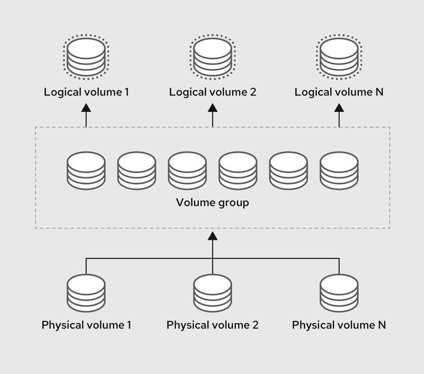
67.1.2. Advantages of LVM
Logical volumes provide the following advantages over using physical storage directly:
- Flexible capacity
- When using logical volumes, you can aggregate devices and partitions into a single logical volume. With this functionality, file systems can extend across multiple devices as though they were a single, large one.
- Convenient device naming
- Logical storage volumes can be managed with user-defined and custom names.
- Resizeable storage volumes
- You can extend logical volumes or reduce logical volumes in size with simple software commands, without reformatting and repartitioning the underlying devices. For more information, see Resizing logical volumes.
- Online data relocation
To deploy newer, faster, or more resilient storage subsystems, you can move data while your system is active using the
pvmovecommand. Data can be rearranged on disks while the disks are in use. For example, you can empty a hot-swappable disk before removing it.For more information on how to migrate the data, see the
pvmoveman page and Removing physical volumes from a volume group.- Striped Volumes
- You can create a logical volume that stripes data across two or more devices. This can dramatically increase throughput. For more information, see Creating a striped logical volume.
- RAID volumes
- Logical volumes provide a convenient way to configure RAID for your data. This provides protection against device failure and improves performance. For more information, see Configuring RAID logical volumes.
- Volume snapshots
- You can take snapshots, which is a point-in-time copy of logical volumes for consistent backups or to test the effect of changes without affecting the real data. For more information, see Managing logical volume snapshots.
- Thin volumes
- Logical volumes can be thin-provisioned. This allows you to create logical volumes that are larger than the available physical space. For more information, see Creating a thin logical volume.
- Caching
- Caching uses fast devices, like SSDs, to cache data from logical volumes, boosting performance. For more information, see Caching logical volumes.
67.2. Managing LVM physical volumes
A physical volume (PV) is a physical storage device or a partition on a storage device that LVM uses.
During the initialization process, an LVM disk label and metadata are written to the device, which allows LVM to track and manage it as part of the logical volume management scheme.
You cannot increase the size of the metadata after the initialization. If you need larger metadata, you must set the appropriate size during the initialization process.
When initialization process is complete, you can allocate the PV to a volume group (VG). You can divide this VG into logical volumes (LVs), which are the virtual block devices that operating systems and applications can use for storage.
To ensure optimal performance, partition the whole disk as a single PV for LVM use.
67.2.1. Creating an LVM physical volume
You can use the pvcreate command to initialize a physical volume LVM usage.
Prerequisites
- Administrative access.
-
The
lvm2package is installed.
Procedure
Identify the storage device you want to use as a physical volume. To list all available storage devices, use:
$ lsblkCreate an LVM physical volume:
# pvcreate /dev/sdbReplace /dev/sdb with the name of the device you want to initialize as a physical volume.
Verification steps
Display the created physical volume:
# pvs PV VG Fmt Attr PSize PFree /dev/sdb lvm2 a-- 28.87g 13.87g
67.2.2. Removing LVM physical volumes
You can use the pvremove command to remove a physical volume for LVM usage.
Prerequisites
- Administrative access.
Procedure
List the physical volumes to identify the device you want to remove:
# pvs PV VG Fmt Attr PSize PFree /dev/sdb1 lvm2 --- 28.87g 28.87gRemove the physical volume:
# pvremove /dev/sdb1Replace /dev/sdb1 with the name of the device associated with the physical volume.
If your physical volume is part of the volume group, you need to remove it from the volume group first.
If you volume group contains more that one physical volume, use the
vgreducecommand:# vgreduce VolumeGroupName /dev/sdb1Replace VolumeGroupName with the name of the volume group. Replace /dev/sdb1 with the name of the device.
If your volume group contains only one physical volume, use
vgremovecommand:# vgremove VolumeGroupNameReplace VolumeGroupName with the name of the volume group.
Verification
Verify the physical volume is removed:
# pvs
67.2.3. Creating logical volumes in the web console
Logical volumes act as physical drives. You can use the RHEL 8 web console to create LVM logical volumes in a volume group.
Prerequisites
- You have installed the RHEL 8 web console.
- You have enabled the cockpit service.
Your user account is allowed to log in to the web console.
For instructions, see Installing and enabling the web console.
-
The
cockpit-storagedpackage is installed on your system. - The volume group is created.
Procedure
Log in to the RHEL 8 web console.
For details, see Logging in to the web console.
- Click Storage.
- In the Storage table, click the volume group in which you want to create logical volumes.
- On the Logical volume group page, scroll to the LVM2 logical volumes section and click .
- In the Name field, enter a name for the new logical volume. Do not include spaces in the name.
In the drop-down menu, select Block device for filesystems.
This configuration enables you to create a logical volume with the maximum volume size which is equal to the sum of the capacities of all drives included in the volume group.

Define the size of the logical volume. Consider:
- How much space the system using this logical volume will need.
- How many logical volumes you want to create.
You do not have to use the whole space. If necessary, you can grow the logical volume later.

Click .
The logical volume is created. To use the logical volume you must format and mount the volume.
Verification
On the Logical volume page, scroll to the LVM2 logical volumes section and verify whether the new logical volume is listed.

67.2.4. Formatting logical volumes in the web console
Logical volumes act as physical drives. To use them, you must format them with a file system.
Formatting logical volumes erases all data on the volume.
The file system you select determines the configuration parameters you can use for logical volumes. For example, the XFS file system does not support shrinking volumes.
Prerequisites
- You have installed the RHEL 8 web console.
- You have enabled the cockpit service.
Your user account is allowed to log in to the web console.
For instructions, see Installing and enabling the web console.
-
The
cockpit-storagedpackage is installed on your system. - The logical volume created.
- You have root access privileges to the system.
Procedure
Log in to the RHEL 8 web console.
For details, see Logging in to the web console.
- Click .
- In the Storage table, click the volume group in the logical volumes is created.
- On the Logical volume group page, scroll to the LVM2 logical volumes section.
- Click the menu button, , next to the volume group you want to format.
From the drop-down menu, select .
- In the Name field, enter a name for the file system.
In the Mount Point field, add the mount path.

In the drop-down menu, select a file system:
XFS file system supports large logical volumes, switching physical drives online without outage, and growing an existing file system. Leave this file system selected if you do not have a different strong preference.
XFS does not support reducing the size of a volume formatted with an XFS file system
ext4 file system supports:
- Logical volumes
- Switching physical drives online without an outage
- Growing a file system
- Shrinking a file system
Select the Overwrite existing data with zeros checkbox if you want the RHEL web console to rewrite the whole disk with zeros. This option is slower because the program has to go through the whole disk, but it is more secure. Use this option if the disk includes any data and you need to overwrite it.
If you do not select the Overwrite existing data with zeros checkbox, the RHEL web console rewrites only the disk header. This increases the speed of formatting.
From the drop-down menu, select the type of encryption if you want to enable it on the logical volume.
You can select a version with either the LUKS1 (Linux Unified Key Setup) or LUKS2 encryption, which allows you to encrypt the volume with a passphrase.
- In the drop-down menu, select when you want the logical volume to mount after the system boots.
- Select the required Mount options.
Format the logical volume:
- If you want to format the volume and immediately mount it, click .
If you want to format the volume without mounting it, click .
Formatting can take several minutes depending on the volume size and which formatting options are selected.
Verification
On the Logical volume group page, scroll to the LVM2 logical volumes section and click the logical volume to check the details and additional options.

- If you selected the option, click the menu button at the end of the line of the logical volume, and select to use the logical volume.
67.2.5. Resizing logical volumes in the web console
You can extend or reduce logical volumes in the RHEL 8 web console. The example procedure demonstrates how to grow and shrink the size of a logical volume without taking the volume offline.
You cannot reduce volumes that contains GFS2 or XFS filesystem.
Prerequisites
- You have installed the RHEL 8 web console.
- You have enabled the cockpit service.
Your user account is allowed to log in to the web console.
For instructions, see Installing and enabling the web console.
-
The
cockpit-storagedpackage is installed on your system. - An existing logical volume containing a file system that supports resizing logical volumes.
Procedure
- Log in to the RHEL web console.
- Click .
- In the Storage table, click the volume group in the logical volumes is created.
On the Logical volume group page, scroll to the LVM2 logical volumes section and click the menu button, , next to volume group you want to resize.
From the menu, select Grow or Shrink to resize the volume:
Growing the Volume:
- Select to increase the size of the volume.
In the Grow logical volume dialog box, adjust the size of the logical volume.

Click .
LVM grows the logical volume without causing a system outage.
Shrinking the Volume:
- Select to reduce the size of the volume.
In the Shrink logical volume dialog box, adjust the size of the logical volume.

Click .
LVM shrinks the logical volume without causing a system outage.
67.3. Managing LVM volume groups
You can create and use volume groups (VGs) to manage and resize multiple physical volumes (PVs) combined into a single storage entity.
Extents are the smallest units of space that you can allocate in LVM. Physical extents (PE) and logical extents (LE) has the default size of 4 MiB that you can configure. All extents have the same size.
When you create a logical volume (LV) within a VG, LVM allocates physical extents on the PVs. The logical extents within the LV correspond one-to-one with physical extents in the VG. You do not need to specify the PEs to create LVs. LVM will locate the available PEs and piece them together to create a LV of the requested size.
Within a VG, you can create multiple LVs, each acting like a traditional partition but with the ability to span across physical volumes and resize dynamically. VGs can manage the allocation of disk space automatically.
67.3.1. Creating an LVM volume group
You can use the vgcreate command to create a volume group (VG). You can adjust the extent size for very large or very small volumes to optimize performance and storage efficiency. You can specify the extent size when creating a VG. To change the extent size you must re-create the volume group.
Prerequisites
- Administrative access.
-
The
lvm2package is installed. - One or more physical volumes are created. For more information about creating physical volumes, see Creating LVM physical volume.
Procedure
List and identify the PV that you want to include in the VG:
# pvsCreate a VG:
# vgcreate VolumeGroupName PhysicalVolumeName1 PhysicalVolumeName2Replace VolumeGroupName with the name of the volume group that you want to create. Replace PhysicalVolumeName with the name of the PV.
To specify the extent size when creating a VG, use the
-s ExtentSizeoption. Replace ExtentSize with the size of the extent. If you provide no size suffix, the command defaults to MB.
Verification
Verify that the VG is created:
# vgs VG #PV #LV #SN Attr VSize VFree VolumeGroupName 1 0 0 wz--n- 28.87g 28.87g
67.3.2. Creating volume groups in the web console
Create volume groups from one or more physical drives or other storage devices.
Logical volumes are created from volume groups. Each volume group can include multiple logical volumes.
Prerequisites
- You have installed the RHEL 8 web console.
- You have enabled the cockpit service.
Your user account is allowed to log in to the web console.
For instructions, see Installing and enabling the web console.
-
The
cockpit-storagedpackage is installed on your system. - Physical drives or other types of storage devices from which you want to create volume groups.
Procedure
Log in to the RHEL 8 web console.
For details, see Logging in to the web console.
- Click .
- In the Storage table, click the menu button.
From the drop-down menu, select Create LVM2 volume group.

- In the Name field, enter a name for the volume group. The name must not include spaces.
Select the drives you want to combine to create the volume group.

The RHEL web console displays only unused block devices. If you do not see your device in the list, make sure that it is not being used by your system, or format it to be empty and unused. Used devices include, for example:
- Devices formatted with a file system
- Physical volumes in another volume group
- Physical volumes being a member of another software RAID device
Click .
The volume group is created.
Verification
- On the Storage page, check whether the new volume group is listed in the Storage table.
67.3.3. Renaming an LVM volume group
You can use the vgrename command to rename a volume group (VG).
Prerequisites
- Administrative access.
-
The
lvm2package is installed. - One or more physical volumes are created. For more information about creating physical volumes, see Creating LVM physical volume.
- The volume group is created. For more information about creating volume groups, see Section 67.3.1, “Creating an LVM volume group”.
Procedure
List and identify the VG that you want to rename:
# vgsRename the VG:
# vgrename OldVolumeGroupName NewVolumeGroupNameReplace OldVolumeGroupName with the name of the VG. Replace NewVolumeGroupName with the new name for the VG.
Verification
Verify that the VG has a new name:
# vgs VG #PV #LV #SN Attr VSize VFree NewVolumeGroupName 1 0 0 wz--n- 28.87g 28.87g
67.3.4. Extending an LVM volume group
You can use the vgextend command to add physical volumes (PVs) to a volume group (VG).
Prerequisites
- Administrative access.
-
The
lvm2package is installed. - One or more physical volumes are created. For more information about creating physical volumes, see Creating LVM physical volume.
- The volume group is created. For more information about creating volume groups, see Section 67.3.1, “Creating an LVM volume group”.
Procedure
List and identify the VG that you want to extend:
# vgsList and identify the PVs that you want to add to the VG:
# pvsExtend the VG:
# vgextend VolumeGroupName PhysicalVolumeNameReplace VolumeGroupName with the name of the VG. Replace PhysicalVolumeName with the name of the PV.
Verification
Verify that the VG now includes the new PV:
# pvs PV VG Fmt Attr PSize PFree /dev/sda VolumeGroupName lvm2 a-- 28.87g 28.87g /dev/sdd VolumeGroupName lvm2 a-- 1.88g 1.88g
67.3.5. Combining LVM volume groups
You can combine two existing volume groups (VGs) with the vgmerge command. The source volume will be merged into the destination volume.
Prerequisites
- Administrative access.
-
The
lvm2package is installed. - One or more physical volumes are created. For more information about creating physical volumes, see Creating LVM physical volume.
- Two or more volume group are created. For more information about creating volume groups, see Section 67.3.1, “Creating an LVM volume group”.
Procedure
List and identify the VG that you want to merge:
# vgs VG #PV #LV #SN Attr VSize VFree VolumeGroupName1 1 0 0 wz--n- 28.87g 28.87g VolumeGroupName2 1 0 0 wz--n- 1.88g 1.88gMerge the source VG into the destination VG:
# vgmerge VolumeGroupName2 VolumeGroupName1Replace VolumeGroupName2 with the name of the source VG. Replace VolumeGroupName1 with the name of the destination VG.
Verification
Verify that the VG now includes the new PV:
# vgs VG #PV #LV #SN Attr VSize VFree VolumeGroupName1 2 0 0 wz--n- 30.75g 30.75g
67.3.6. Removing physical volumes from a volume group
To remove unused physical volumes (PVs) from a volume group (VG), use the vgreduce command. The vgreduce command shrinks a volume group’s capacity by removing one or more empty physical volumes. This frees those physical volumes to be used in different volume groups or to be removed from the system.
Procedure
If the physical volume is still being used, migrate the data to another physical volume from the same volume group:
# pvmove /dev/vdb3 /dev/vdb3: Moved: 2.0% ... /dev/vdb3: Moved: 79.2% ... /dev/vdb3: Moved: 100.0%If there are not enough free extents on the other physical volumes in the existing volume group:
Create a new physical volume from /dev/vdb4:
# pvcreate /dev/vdb4 Physical volume "/dev/vdb4" successfully createdAdd the newly created physical volume to the volume group:
# vgextend VolumeGroupName /dev/vdb4 Volume group "VolumeGroupName" successfully extendedMove the data from /dev/vdb3 to /dev/vdb4:
# pvmove /dev/vdb3 /dev/vdb4 /dev/vdb3: Moved: 33.33% /dev/vdb3: Moved: 100.00%
Remove the physical volume /dev/vdb3 from the volume group:
# vgreduce VolumeGroupName /dev/vdb3 Removed "/dev/vdb3" from volume group "VolumeGroupName"
Verification
Verify that the /dev/vdb3 physical volume is removed from the VolumeGroupName volume group:
# pvs PV VG Fmt Attr PSize PFree Used /dev/vdb1 VolumeGroupName lvm2 a-- 1020.00m 0 1020.00m /dev/vdb2 VolumeGroupName lvm2 a-- 1020.00m 0 1020.00m /dev/vdb3 lvm2 a-- 1020.00m 1008.00m 12.00m
67.3.7. Splitting a LVM volume group
If there is enough unused space on the physical volumes, a new volume group can be created without adding new disks.
In the initial setup, the volume group VolumeGroupName1 consists of /dev/vdb1, /dev/vdb2, and /dev/vdb3. After completing this procedure, the volume group VolumeGroupName1 will consist of /dev/vdb1 and /dev/vdb2, and the second volume group, VolumeGroupName2, will consist of /dev/vdb3.
Prerequisites
-
You have sufficient space in the volume group. Use the
vgscancommand to determine how much free space is currently available in the volume group. -
Depending on the free capacity in the existing physical volume, move all the used physical extents to other physical volume using the
pvmovecommand. For more information, see Removing physical volumes from a volume group.
Procedure
Split the existing volume group VolumeGroupName1 to the new volume group VolumeGroupName2:
# vgsplit VolumeGroupName1 VolumeGroupName2 /dev/vdb3 Volume group "VolumeGroupName2" successfully split from "VolumeGroupName1"NoteIf you have created a logical volume using the existing volume group, use the following command to deactivate the logical volume:
# lvchange -a n /dev/VolumeGroupName1/LogicalVolumeNameView the attributes of the two volume groups:
# vgs VG #PV #LV #SN Attr VSize VFree VolumeGroupName1 2 1 0 wz--n- 34.30G 10.80G VolumeGroupName2 1 0 0 wz--n- 17.15G 17.15G
Verification
Verify that the newly created volume group VolumeGroupName2 consists of /dev/vdb3 physical volume:
# pvs PV VG Fmt Attr PSize PFree Used /dev/vdb1 VolumeGroupName1 lvm2 a-- 1020.00m 0 1020.00m /dev/vdb2 VolumeGroupName1 lvm2 a-- 1020.00m 0 1020.00m /dev/vdb3 VolumeGroupName2 lvm2 a-- 1020.00m 1008.00m 12.00m
67.3.8. Moving a volume group to another system
You can move an entire LVM volume group (VG) to another system using the following commands:
vgexport- Use this command on an existing system to make an inactive VG inaccessible to the system. Once the VG is inaccessible, you can detach its physical volumes (PV).
vgimport- Use this command on the other system to make the VG, which was inactive in the old system, accessible in the new system.
Prerequisites
- No users are accessing files on the active volumes in the volume group that you are moving.
Procedure
Unmount the LogicalVolumeName logical volume:
# umount /dev/mnt/LogicalVolumeNameDeactivate all logical volumes in the volume group, which prevents any further activity on the volume group:
# vgchange -an VolumeGroupName vgchange -- volume group "VolumeGroupName" successfully deactivatedExport the volume group to prevent it from being accessed by the system from which you are removing it:
# vgexport VolumeGroupName vgexport -- volume group "VolumeGroupName" successfully exportedView the exported volume group:
# pvscan PV /dev/sda1 is in exported VG VolumeGroupName [17.15 GB / 7.15 GB free] PV /dev/sdc1 is in exported VG VolumeGroupName [17.15 GB / 15.15 GB free] PV /dev/sdd1 is in exported VG VolumeGroupName [17.15 GB / 15.15 GB free] ...- Shut down your system and unplug the disks that make up the volume group and connect them to the new system.
Plug the disks into the new system and import the volume group to make it accessible to the new system:
# vgimport VolumeGroupNameNoteYou can use the
--forceargument of thevgimportcommand to import volume groups that are missing physical volumes and subsequently run thevgreduce --removemissingcommand.Activate the volume group:
# vgchange -ay VolumeGroupNameMount the file system to make it available for use:
# mkdir -p /mnt/VolumeGroupName/users # mount /dev/VolumeGroupName/users /mnt/VolumeGroupName/users
Additional resources
-
vgimport(8),vgexport(8), andvgchange(8)man pages on your system
67.3.9. Removing LVM volume groups
You can remove an existing volume group using the vgremove command. Only volume groups that do not contain logical volumes can be removed.
Prerequisites
- Administrative access.
Procedure
Ensure the volume group does not contain logical volumes:
# vgs -o vg_name,lv_count VolumeGroupName VG #LV VolumeGroupName 0Replace VolumeGroupName with the name of the volume group.
Remove the volume group:
# vgremove VolumeGroupNameReplace VolumeGroupName with the name of the volume group.
67.3.10. Removing LVM volume groups in a cluster environment
In a cluster environment, LVM uses the lockspace <qualifier> to coordinate access to volume groups shared among multiple machines. You must stop the lockspace before removing a volume group to make sure no other node is trying to access or modify it during the removal process.
Prerequisites
- Administrative access.
- The volume group contains no logical volumes.
Procedure
Ensure the volume group does not contain logical volumes:
# vgs -o vg_name,lv_count VolumeGroupName VG #LV VolumeGroupName 0Replace VolumeGroupName with the name of the volume group.
Stop the
lockspaceon all nodes except the node where you are removing the volume group:# vgchange --lockstop VolumeGroupNameReplace VolumeGroupName with the name of the volume group and wait for the lock to stop.
Remove the volume group:
# vgremove VolumeGroupNameReplace VolumeGroupName with the name of the volume group.
67.4. Managing LVM logical volumes
A logical volume is a virtual, block storage device that a file system, database, or application can use. To create an LVM logical volume, the physical volumes (PVs) are combined into a volume group (VG). This creates a pool of disk space out of which LVM logical volumes (LVs) can be allocated.
67.4.1. Overview of logical volume features
With the Logical Volume Manager (LVM), you can manage disk storage in a flexible and efficient way that traditional partitioning schemes cannot offer. Below is a summary of key LVM features that are used for storage management and optimization.
- Concatenation
- Concatenation involves combining space from one or more physical volumes into a singular logical volume, effectively merging the physical storage.
- Striping
- Striping optimizes data I/O efficiency by distributing data across multiple physical volumes. This method enhances performance for sequential reads and writes by allowing parallel I/O operations.
- RAID
- LVM supports RAID levels 0, 1, 4, 5, 6, and 10. When you create a RAID logical volume, LVM creates a metadata subvolume that is one extent in size for every data or parity subvolume in the array.
- Thin provisioning
- Thin provisioning enables the creation of logical volumes that are larger than the available physical storage. With thin provisioning, the system dynamically allocates storage based on actual usage instead of allocating a predetermined amount upfront.
- Snapshots
- With LVM snapshots, you can create point-in-time copies of logical volumes. A snapshot starts empty. As changes occur on the original logical volume, the snapshot captures the pre-change states through copy-on-write (CoW), growing only with changes to preserve the state of the original logical volume.
- Caching
- LVM supports the use of fast block devices, such as SSD drives as write-back or write-through caches for larger slower block devices. Users can create cache logical volumes to improve the performance of their existing logical volumes or create new cache logical volumes composed of a small and fast device coupled with a large and slow device.
67.4.2. Managing logical volume snapshots
A snapshot is a logical volume (LV) that mirrors the content of another LV at a specific point in time.
67.4.2.1. Understanding logical volume snapshots
When you create a snapshot, you are creating a new LV that serves as a point-in-time copy of another LV. Initially, the snapshot LV contains no actual data. Instead, it references the data blocks of the original LV at the moment of snapshot creation.
It is important to regularly monitor the snapshot’s storage usage. If a snapshot reaches 100% of its allocated space, it will become invalid.
It is essential to extend the snapshot before it gets completely filled. This can be done manually by using the lvextend command or automatically via the /etc/lvm/lvm.conf file.
- Thick LV snapshots
- When data on the original LV changes, the copy-on-write (CoW) system copies the original, unchanged data to the snapshot before the change is made. This way, the snapshot grows in size only as changes occur, storing the state of the original volume at the time of the snapshot’s creation. Thick snapshots are a type of LV that requires you to allocate some amount of storage space upfront. This amount can later be extended or reduced, however, you should consider what type of changes you intend to make to the original LV. This helps you to avoid either wasting resources by allocating too much space or needing to frequently increase the snapshot size if you allocate too little.
- Thin LV snapshots
Thin snapshots are a type of LV created from an existing thin provisioned LV. Thin snapshots do not require allocating extra space upfront. Initially, both the original LV and its snapshot share the same data blocks. When changes are made to the original LV, it writes new data to different blocks, while the snapshot continues to reference the original blocks, preserving a point-in-time view of the LV’s data at the snapshot creation.
Thin provisioning is a method of optimizing and managing storage efficiently by allocating disk space on an as-needed basis. This means that you can create multiple LVs without needing to allocate a large amount of storage upfront for each LV. The storage is shared among all LVs in a thin pool, making it a more efficient use of resources. A thin pool allocates space on-demand to its LVs.
- Choosing between thick and thin LV snapshots
- The choice between thick or thin LV snapshots is directly determined by the type of LV you are taking a snapshot of. If your original LV is a thick LV, your snapshots will be thick. If your original LV is thin, your snapshots will be thin.
67.4.2.2. Managing thick logical volume snapshots
When you create a thick LV snapshot, it is important to consider the storage requirements and the intended lifespan of your snapshot. You need to allocate enough storage for it based on the expected changes to the original volume. The snapshot must have a sufficient size to capture changes during its intended lifespan, but it cannot exceed the size of the original LV. If you expect a low rate of change, a smaller snapshot size of 10%-15% might be sufficient. For LVs with a high rate of change, you might need to allocate 30% or more.
It is essential to extend the snapshot before it gets completely filled. If a snapshot reaches 100% of its allocated space, it becomes invalid. You can monitor the snapshot capacity with the lvs -o lv_name,data_percent,origin command.
67.4.2.2.1. Creating thick logical volume snapshots
You can create a thick LV snapshot with the lvcreate command.
Prerequisites
- Administrative access.
- You have created a physical volume. For more information, see Creating LVM physical volume.
- You have created a volume group. For more information, see Creating LVM volume group.
- You have created a logical volume. For more information, see Creating logical volumes.
Procedure
Identify the LV of which you want to create a snapshot:
# lvs -o vg_name,lv_name,lv_size VG LV LSize VolumeGroupName LogicalVolumeName 10.00gThe size of the snapshot cannot exceed the size of the LV.
Create a thick LV snapshot:
# lvcreate --snapshot --size SnapshotSize --name SnapshotName VolumeGroupName/LogicalVolumeNameReplace SnapshotSize with the size you want to allocate for the snapshot (e.g. 10G). Replace SnapshotName with the name you want to give to the snapshot logical volume. Replace VolumeGroupName with the name of the volume group that contains the original logical volume. Replace LogicalVolumeName with the name of the logical volume that you want to create a snapshot of.
Verification
Verify that the snapshot is created:
# lvs -o lv_name,origin LV Origin LogicalVolumeName SnapshotName LogicalVolumeName
67.4.2.2.2. Manually extending logical volume snapshots
If a snapshot reaches 100% of its allocated space, it becomes invalid. It is essential to extend the snapshot before it gets completely filled. This can be done manually by using the lvextend command.
Prerequisites
- Administrative access.
Procedure
List the names of volume groups, logical volumes, source volumes for snapshots, their usage percentages, and sizes:
# lvs -o vg_name,lv_name,origin,data_percent,lv_size VG LV Origin Data% LSize VolumeGroupName LogicalVolumeName 10.00g VolumeGroupName SnapshotName LogicalVolumeName 82.00 5.00gExtend the thick-provisioned snapshot:
# lvextend --size +AdditionalSize VolumeGroupName/SnapshotNameReplace AdditionalSize with how much space to add to the snapshot (for example, +1G). Replace VolumeGroupName with the name of the volume group. Replace SnapshotName with the name of the snapshot.
Verification
Verify that the LV is extended:
# lvs -o vg_name,lv_name,origin,data_percent,lv_size VG LV Origin Data% LSize VolumeGroupName LogicalVolumeName 10.00g VolumeGroupName SnapshotName LogicalVolumeName 68.33 6.00g
67.4.2.2.3. Automatically extending thick logical volume snapshots
If a snapshot reaches 100% of its allocated space, it becomes invalid. It is essential to extend the snapshot before it gets completely filled. This can be done automatically.
Prerequisites
- Administrative access.
Procedure
-
As the
rootuser, open the/etc/lvm/lvm.conffile in an editor of your choice. Uncomment the
snapshot_autoextend_thresholdandsnapshot_autoextend_percentlines and set each parameter to a required value:snapshot_autoextend_threshold = 70 snapshot_autoextend_percent = 20snapshot_autoextend_thresholddetermines the percentage at which LVM starts to auto-extend the snapshot. For example, setting the parameter to 70 means that LVM will try to extend the snapshot when it reaches 70% capacity.snapshot_autoextend_percentspecifies by what percentage the snapshot should be extended when it reaches the threshold. For example, setting the parameter to 20 means the snapshot will be increased by 20% of its current size.- Save the changes and exit the editor.
Restart the
lvm2-monitor:# systemctl restart lvm2-monitor
67.4.2.2.4. Merging thick logical volume snapshots
You can merge thick LV snapshot into the original logical volume from which the snapshot was created. The process of merging means that the original LV is reverted to the state it was in when the snapshot was created. Once the merge is complete, the snapshot is removed.
The merge between the original and snapshot LV is postponed if either is active. It only proceeds once the LVs are reactivated and not in use.
Prerequisites
- Administrative access.
Procedure
List the LVs, their volume groups, and their paths:
# lvs -o lv_name,vg_name,lv_path LV VG Path LogicalVolumeName VolumeGroupName /dev/VolumeGroupName/LogicalVolumeName SnapshotName VolumeGroupName /dev/VolumeGroupName/SnapshotNameCheck where the LVs are mounted:
# findmnt -o SOURCE,TARGET /dev/VolumeGroupName/LogicalVolumeName # findmnt -o SOURCE,TARGET /dev/VolumeGroupName/SnapshotNameReplace /dev/VolumeGroupName/LogicalVolumeName with the path to your logical volume. Replace /dev/VolumeGroupName/SnapshotName with the path to your snapshot.
Unmount the LVs:
# umount /LogicalVolume/MountPoint # umount /Snapshot/MountPointReplace /LogicalVolume/MountPoint with the mounting point for your logical volume. Replace /Snapshot/MountPoint with the mounting point for your snapshot.
Deactivate the LVs:
# lvchange --activate n VolumeGroupName/LogicalVolumeName # lvchange --activate n VolumeGroupName/SnapshotNameReplace VolumeGroupName with the name of the volume group. Replace LogicalVolumeName with the name of the logical volume. Replace SnapshotName with the name of your snapshot.
Merge the thick LV snapshot into the origin:
# lvconvert --merge SnapshotNameReplace SnapshotName with the name of the snapshot.
Activate the LV:
# lvchange --activate y VolumeGroupName/LogicalVolumeNameReplace VolumeGroupName with the name of the volume group. Replace LogicalVolumeName with the name of the logical volume.
Mount the LV:
# umount /LogicalVolume/MountPointReplace /LogicalVolume/MountPoint with the mounting point for your logical volume.
Verification
Verify that the snapshot is removed:
# lvs -o lv_name
67.4.2.3. Managing thin logical volume snapshots
Thin provisioning is appropriate where storage efficiency is a priority. Storage space dynamic allocation reduces initial storage costs and maximizes the use of available storage resources. In environments with dynamic workloads or where storage grows over time, thin provisioning allows for flexibility. It enables the storage system to adapt to changing needs without requiring large upfront allocations of the storage space. With dynamic allocation, over-provisioning is possible, where the total size of all LVs can exceed the physical size of the thin pool, under the assumption that not all space will be utilized at the same time.
67.4.2.3.1. Creating thin logical volume snapshots
You can create a thin LV snapshot with the lvcreate command. When creating a thin LV snapshot, avoid specifying the snapshot size. Including a size parameter results in the creation of a thick snapshot instead.
Prerequisites
- Administrative access.
- You have created a physical volume. For more information, see Creating LVM physical volume.
- You have created a volume group. For more information, see Creating LVM volume group.
- You have created a logical volume. For more information, see Creating logical volumes.
Procedure
Identify the LV of which you want to create a snapshot:
# lvs -o lv_name,vg_name,pool_lv,lv_size LV VG Pool LSize PoolName VolumeGroupName 152.00m ThinVolumeName VolumeGroupName PoolName 100.00mCreate a thin LV snapshot:
# lvcreate --snapshot --name SnapshotName VolumeGroupName/ThinVolumeNameReplace SnapshotName with the name you want to give to the snapshot logical volume. Replace VolumeGroupName with the name of the volume group that contains the original logical volume. Replace ThinVolumeName with the name of the thin logical volume that you want to create a snapshot of.
Verification
Verify that the snapshot is created:
# lvs -o lv_name,origin LV Origin PoolName SnapshotName ThinVolumeName ThinVolumeName
67.4.2.3.2. Merging thin logical volume snapshots
You can merge thin LV snapshot into the original logical volume from which the snapshot was created. The process of merging means that the original LV is reverted to the state it was in when the snapshot was created. Once the merge is complete, the snapshot is removed.
Prerequisites
- Administrative access.
Procedure
List the LVs, their volume groups, and their paths:
# lvs -o lv_name,vg_name,lv_path LV VG Path ThinPoolName VolumeGroupName ThinSnapshotName VolumeGroupName /dev/VolumeGroupName/ThinSnapshotName ThinVolumeName VolumeGroupName /dev/VolumeGroupName/ThinVolumeNameCheck where the original LV is mounted:
# findmnt -o SOURCE,TARGET /dev/VolumeGroupName/ThinVolumeNameReplace VolumeGroupName/ThinVolumeName with the path to your logical volume.
Unmount the LV:
# umount /ThinLogicalVolume/MountPointReplace /ThinLogicalVolume/MountPoint with the mounting point for your logical volume. Replace /ThinSnapshot/MountPoint with the mounting point for your snapshot.
Deactivate the LV:
# lvchange --activate n VolumeGroupName/ThinLogicalVolumeNameReplace VolumeGroupName with the name of the volume group. Replace ThinLogicalVolumeName with the name of the logical volume.
Merge the thin LV snapshot into the origin:
# lvconvert --mergethin VolumeGroupName/ThinSnapshotNameReplace VolumeGroupName with the name of the volume group. Replace ThinSnapshotName with the name of the snapshot.
Mount the LV:
# umount /ThinLogicalVolume/MountPointReplace /ThinLogicalVolume/MountPoint with the mounting point for your logical volume.
Verification
Verify that the original LV is merged:
# lvs -o lv_name
67.4.3. Creating a RAID0 striped logical volume
A RAID0 logical volume spreads logical volume data across multiple data subvolumes in units of stripe size. The following procedure creates an LVM RAID0 logical volume called mylv that stripes data across the disks.
Prerequisites
- You have created three or more physical volumes. For more information about creating physical volumes, see Creating LVM physical volume.
- You have created the volume group. For more information, see Creating LVM volume group.
Procedure
Create a RAID0 logical volume from the existing volume group. The following command creates the RAID0 volume mylv from the volume group myvg, which is 2G in size, with three stripes and a stripe size of 4kB:
# lvcreate --type raid0 -L 2G --stripes 3 --stripesize 4 -n mylv my_vg Rounding size 2.00 GiB (512 extents) up to stripe boundary size 2.00 GiB(513 extents). Logical volume "mylv" created.Create a file system on the RAID0 logical volume. The following command creates an ext4 file system on the logical volume:
# mkfs.ext4 /dev/my_vg/mylvMount the logical volume and report the file system disk space usage:
# mount /dev/my_vg/mylv /mnt # df Filesystem 1K-blocks Used Available Use% Mounted on /dev/mapper/my_vg-mylv 2002684 6168 1875072 1% /mnt
Verification
View the created RAID0 stripped logical volume:
# lvs -a -o +devices,segtype my_vg LV VG Attr LSize Pool Origin Data% Meta% Move Log Cpy%Sync Convert Devices Type mylv my_vg rwi-a-r--- 2.00g mylv_rimage_0(0),mylv_rimage_1(0),mylv_rimage_2(0) raid0 [mylv_rimage_0] my_vg iwi-aor--- 684.00m /dev/sdf1(0) linear [mylv_rimage_1] my_vg iwi-aor--- 684.00m /dev/sdg1(0) linear [mylv_rimage_2] my_vg iwi-aor--- 684.00m /dev/sdh1(0) linear
67.4.4. Removing a disk from a logical volume
This procedure describes how to remove a disk from an existing logical volume, either to replace the disk or to use the disk as part of a different volume.
In order to remove a disk, you must first move the extents on the LVM physical volume to a different disk or set of disks.
Procedure
View the used and free space of physical volumes when using the LV:
# pvs -o+pv_used PV VG Fmt Attr PSize PFree Used /dev/vdb1 myvg lvm2 a-- 1020.00m 0 1020.00m /dev/vdb2 myvg lvm2 a-- 1020.00m 0 1020.00m /dev/vdb3 myvg lvm2 a-- 1020.00m 1008.00m 12.00mMove the data to other physical volume:
If there are enough free extents on the other physical volumes in the existing volume group, use the following command to move the data:
# pvmove /dev/vdb3 /dev/vdb3: Moved: 2.0% ... /dev/vdb3: Moved: 79.2% ... /dev/vdb3: Moved: 100.0%If there are no enough free extents on the other physical volumes in the existing volume group, use the following commands to add a new physical volume, extend the volume group using the newly created physical volume, and move the data to this physical volume:
# pvcreate /dev/vdb4 Physical volume "/dev/vdb4" successfully created # vgextend myvg /dev/vdb4 Volume group "myvg" successfully extended # pvmove /dev/vdb3 /dev/vdb4 /dev/vdb3: Moved: 33.33% /dev/vdb3: Moved: 100.00%
Remove the physical volume:
# vgreduce myvg /dev/vdb3 Removed "/dev/vdb3" from volume group "myvg"If a logical volume contains a physical volume that fails, you cannot use that logical volume. To remove missing physical volumes from a volume group, you can use the
--removemissingparameter of thevgreducecommand, if there are no logical volumes that are allocated on the missing physical volumes:# vgreduce --removemissing myvg
67.4.5. Changing physical drives in volume groups using the web console
You can change the drive in a volume group using the RHEL 8 web console.
Prerequisites
- A new physical drive for replacing the old or broken one.
- The configuration expects that physical drives are organized in a volume group.
67.4.5.1. Adding physical drives to volume groups in the web console
You can add a new physical drive or other type of volume to the existing logical volume by using the RHEL 8 web console.
Prerequisites
- You have installed the RHEL 8 web console.
- You have enabled the cockpit service.
Your user account is allowed to log in to the web console.
For instructions, see Installing and enabling the web console.
-
The
cockpit-storagedpackage is installed on your system. - A volume group must be created.
- A new drive connected to the machine.
Procedure
Log in to the RHEL 8 web console.
For details, see Logging in to the web console.
- Click Storage.
- In the Storage table, click the volume group to which you want to add physical drives.
- On the LVM2 volume group page, click .
- In the Add Disks dialog box, select the preferred drives and click .
Verification
- On the LVM2 volume group page, check the Physical volumes section to verify whether the new physical drives are available in the volume group.
67.4.5.2. Removing physical drives from volume groups in the web console
If a logical volume includes multiple physical drives, you can remove one of the physical drives online.
The system moves automatically all data from the drive to be removed to other drives during the removal process. Notice that it can take some time.
The web console also verifies, if there is enough space for removing the physical drive.
Prerequisites
- You have installed the RHEL 8 web console.
- You have enabled the cockpit service.
Your user account is allowed to log in to the web console.
For instructions, see Installing and enabling the web console.
-
The
cockpit-storagedpackage is installed on your system. - A volume group with more than one physical drive connected.
Procedure
- Log in to the RHEL 8 web console.
- Click Storage.
- In the Storage table, click the volume group to which you want to add physical drives.
- On the LVM2 volume group page, scroll to the Physical volumes section.
- Click the menu button, , next to the physical volume you want to remove.
From the drop-down menu, select .
The RHEL 8 web console verifies whether the logical volume has enough free space to removing the disk. If there is no free space to transfer the data, you cannot remove the disk and you must first add another disk to increase the capacity of the volume group. For details, see Adding physical drives to logical volumes in the web console.
67.4.6. Removing logical volumes
You can remove an existing logical volume, including snapshots, using the lvremove command.
Prerequisites
- Administrative access.
Procedure
List the logical volumes and their paths:
# lvs -o lv_name,lv_path LV Path LogicalVolumeName /dev/VolumeGroupName/LogicalVolumeNameCheck where the logical volume is mounted:
# findmnt -o SOURCE,TARGET /dev/VolumeGroupName/LogicalVolumeName SOURCE TARGET /dev/mapper/VolumeGroupName-LogicalVolumeName /MountPointReplace /dev/VolumeGroupName/LogicalVolumeName with the path to your logical volume.
Unmount the logical volume:
# umount /MountPointReplace /MountPoint with the mounting point for your logical volume.
Remove the logical volume:
# lvremove VolumeGroupName/LogicalVolumeNameReplace VolumeGroupName/LogicalVolumeName with the path to your logical volume.
67.4.7. Managing LVM logical volumes by using RHEL system roles
Use the storage role to perform the following tasks:
- Create an LVM logical volume in a volume group consisting of multiple disks.
- Create an ext4 file system with a given label on the logical volume.
- Persistently mount the ext4 file system.
Prerequisites
-
An Ansible playbook including the
storagerole
67.4.7.1. Creating or resizing a logical volume by using the storage RHEL system role
Use the storage role to perform the following tasks:
- To create an LVM logical volume in a volume group consisting of many disks
- To resize an existing file system on LVM
- To express an LVM volume size in percentage of the pool’s total size
If the volume group does not exist, the role creates it. If a logical volume exists in the volume group, it is resized if the size does not match what is specified in the playbook.
If you are reducing a logical volume, to prevent data loss you must ensure that the file system on that logical volume is not using the space in the logical volume that is being reduced.
Prerequisites
- You have prepared the control node and the managed nodes
- You are logged in to the control node as a user who can run playbooks on the managed nodes.
-
The account you use to connect to the managed nodes has
sudopermissions on them.
Procedure
Create a playbook file, for example
~/playbook.yml, with the following content:--- - name: Manage local storage hosts: managed-node-01.example.com tasks: - name: Create logical volume ansible.builtin.include_role: name: redhat.rhel_system_roles.storage vars: storage_pools: - name: myvg disks: - sda - sdb - sdc volumes: - name: mylv size: 2G fs_type: ext4 mount_point: /mnt/dataThe settings specified in the example playbook include the following:
size: <size>- You must specify the size by using units (for example, GiB) or percentage (for example, 60%).
For details about all variables used in the playbook, see the
/usr/share/ansible/roles/rhel-system-roles.storage/README.mdfile on the control node.Validate the playbook syntax:
$ ansible-playbook --syntax-check ~/playbook.ymlNote that this command only validates the syntax and does not protect against a wrong but valid configuration.
Run the playbook:
$ ansible-playbook ~/playbook.yml
Verification
Verify that specified volume has been created or resized to the requested size:
# ansible managed-node-01.example.com -m command -a 'lvs myvg'
67.4.8. Resizing an existing file system on LVM by using the storage RHEL system role
You can use the storage RHEL system role to resize an LVM logical volume with a file system.
If the logical volume you are reducing has a file system, to prevent data loss you must ensure that the file system is not using the space in the logical volume that is being reduced.
Prerequisites
- You have prepared the control node and the managed nodes
- You are logged in to the control node as a user who can run playbooks on the managed nodes.
-
The account you use to connect to the managed nodes has
sudopermissions on them.
Procedure
Create a playbook file, for example
~/playbook.yml, with the following content:--- - name: Manage local storage hosts: managed-node-01.example.com tasks: - name: Resize LVM logical volume with file system ansible.builtin.include_role: name: redhat.rhel_system_roles.storage vars: storage_pools: - name: myvg disks: - /dev/sda - /dev/sdb - /dev/sdc volumes: - name: mylv1 size: 10 GiB fs_type: ext4 mount_point: /opt/mount1 - name: mylv2 size: 50 GiB fs_type: ext4 mount_point: /opt/mount2This playbook resizes the following existing file systems:
-
The Ext4 file system on the
mylv1volume, which is mounted at/opt/mount1, resizes to 10 GiB. -
The Ext4 file system on the
mylv2volume, which is mounted at/opt/mount2, resizes to 50 GiB.
For details about all variables used in the playbook, see the
/usr/share/ansible/roles/rhel-system-roles.storage/README.mdfile on the control node.-
The Ext4 file system on the
Validate the playbook syntax:
$ ansible-playbook --syntax-check ~/playbook.ymlNote that this command only validates the syntax and does not protect against a wrong but valid configuration.
Run the playbook:
$ ansible-playbook ~/playbook.yml
Verification
Verify that the logical volume has been resized to the requested size:
# ansible managed-node-01.example.com -m command -a 'lvs myvg'Verify file system size using file system tools. For example, for ext4, calculate the file system size by multiplying block count and block size reported by dumpe2fs tool:
# ansible managed-node-01.example.com -m command -a 'dumpe2fs -h /dev/myvg/mylv | grep -E "Block count|Block size"'
67.5. Modifying the size of a logical volume
After you have created a logical volume, you can modify the size of the volume.
67.5.1. Extending a striped logical volume
You can extend a striped logical volume (LV) by using the lvextend command with the required size.
Prerequisites
- You have enough free space on the underlying physical volumes (PVs) that make up the volume group (VG) to support the stripe.
Procedure
Optional: Display your volume group:
# vgs VG #PV #LV #SN Attr VSize VFree myvg 2 1 0 wz--n- 271.31G 271.31GOptional: Create a stripe using the entire amount of space in the volume group:
# lvcreate -n stripe1 -L 271.31G -i 2 myvg Using default stripesize 64.00 KB Rounding up size to full physical extent 271.31 GiBOptional: Extend the myvg volume group by adding new physical volumes:
# vgextend myvg /dev/sdc1 Volume group "myvg" successfully extendedRepeat this step to add sufficient physical volumes depending on your stripe type and the amount of space used. For example, for a two-way stripe that uses up the entire volume group, you need to add at least two physical volumes.
Extend the striped logical volume stripe1 that is a part of the myvg VG:
# lvextend myvg/stripe1 -L 542G Using stripesize of last segment 64.00 KB Extending logical volume stripe1 to 542.00 GB Logical volume stripe1 successfully resizedYou can also extend the stripe1 logical volume to fill all of the unallocated space in the myvg volume group:
# lvextend -l+100%FREE myvg/stripe1 Size of logical volume myvg/stripe1 changed from 1020.00 MiB (255 extents) to <2.00 GiB (511 extents). Logical volume myvg/stripe1 successfully resized.
Verification
Verify the new size of the extended striped LV:
# lvs LV VG Attr LSize Pool Origin Data% Move Log Copy% Convert stripe1 myvg wi-ao---- 542.00 GB
67.6. Customizing the LVM report
LVM provides a wide range of configuration and command line options to produce customized reports. You can sort the output, specify units, use selection criteria, and update the lvm.conf file to customize the LVM report.
67.6.1. Controlling the format of the LVM display
When you use the pvs, lvs, or vgs command without additional options, you see the default set of fields displayed in the default sort order. The default fields for the pvs command include the following information sorted by the name of physical volumes:
# pvs
PV VG Fmt Attr PSize PFree
/dev/vdb1 VolumeGroupName lvm2 a-- 17.14G 17.14G
/dev/vdb2 VolumeGroupName lvm2 a-- 17.14G 17.09G
/dev/vdb3 VolumeGroupName lvm2 a-- 17.14G 17.14GPV- Physical volume name.
VG- Volume group name.
Fmt-
Metadata format of the physical volume:
lvm2orlvm1. Attr- Status of the physical volume: (a) - allocatable or (x) - exported.
PSize- Size of the physical volume.
PFree- Free space remaining on the physical volume.
Displaying custom fields
To display a different set of fields than the default, use the -o option. The following example displays only the name, size and free space of the physical volumes:
# pvs -o pv_name,pv_size,pv_free
PV PSize PFree
/dev/vdb1 17.14G 17.14G
/dev/vdb2 17.14G 17.09G
/dev/vdb3 17.14G 17.14GSorting the LVM display
To sort the results by specific criteria, use the -O option. The following example sorts the entries by the free space of their physical volumes in ascending order:
# pvs -o pv_name,pv_size,pv_free -O pv_free
PV PSize PFree
/dev/vdb2 17.14G 17.09G
/dev/vdb1 17.14G 17.14G
/dev/vdb3 17.14G 17.14G
To sort the results by descending order, use the -O option along with the - character:
# pvs -o pv_name,pv_size,pv_free -O -pv_free
PV PSize PFree
/dev/vdb1 17.14G 17.14G
/dev/vdb3 17.14G 17.14G
/dev/vdb2 17.14G 17.09G67.6.2. Specifying the units for an LVM display
You can view the size of the LVM devices in base 2 or base 10 units by specifying the --units argument of an LVM display command. See the following table for all arguments:
| Units type | Description | Available options | Default |
|---|---|---|---|
| Base 2 units | Units are displayed in powers of 2 (multiples of 1024). |
|
|
| Base 10 units | Units are displayed in multiples of 1000. |
| N/A |
| Custom units |
Combination of a quantity with a base 2 or base 10 unit. For example, to display the results in 4 mebibytes, use | N/A | N/A |
If you do not specify a value for the units, human-readable format (
r) is used by default. The followingvgscommand displays the size of VGs in human-readable format. The most suitable unit is used and the rounding indicator<shows that the actual size is an approximation and it is less than 931 gibibytes.# vgs myvg VG #PV #LV #SN Attr VSize VFree myvg 1 1 0 wz-n <931.00g <930.00gThe following
pvscommand displays the output in base 2 gibibyte units for the/dev/vdbphysical volume:# pvs --units g /dev/vdb PV VG Fmt Attr PSize PFree /dev/vdb myvg lvm2 a-- 931.00g 930.00gThe following
pvscommand displays the output in base 10 gigabyte units for the/dev/vdbphysical volume:# pvs --units G /dev/vdb PV VG Fmt Attr PSize PFree /dev/vdb myvg lvm2 a-- 999.65G 998.58GThe following
pvscommand displays the output in 512-byte sectors:# pvs --units s PV VG Fmt Attr PSize PFree /dev/vdb myvg lvm2 a-- 1952440320S 1950343168SYou can specify custom units for an LVM display command. The following example displays the output of the
pvscommand in units of 4 mebibytes:# pvs --units 4m PV VG Fmt Attr PSize PFree /dev/vdb myvg lvm2 a-- 238335.00U 238079.00U
67.6.3. Customizing the LVM configuration file
You can customize your LVM configuration according to your specific storage and system requirements by editing the lvm.conf file. For example, you can edit the lvm.conf file to modify filter settings, configure volume group auto activation, manage a thin pool, or automatically extend a snapshot.
Procedure
-
Open the
lvm.conffile in an editor of your choice. Customize the
lvm.conffile by uncommenting and modifying the setting for which you want to modify the default display values.To customize what fields you see in the
lvsoutput, uncomment thelvs_colsparameter and modify it:lvs_cols="lv_name,vg_name,lv_attr"To hide empty fields for the
pvs,vgs, andlvscommands, uncomment thecompact_output=1setting:compact_output = 1To set gigabytes as the default unit for the
pvs,vgs, andlvscommands, replace theunits = "r"setting withunits = "G":units = "G"
Ensure that the corresponding section of the
lvm.conffile is uncommented. For example, to modify thelvs_colsparameter, thereportsection must be uncommented:report { ... }
Verification
View the changed values after modifying the
lvm.conffile:# lvmconfig --typeconfig diff
67.6.4. Defining LVM selection criteria
Selection criteria are a set of statements in the form of <field> <operator> <value>, which use comparison operators to define values for specific fields. Objects that match the selection criteria are then processed or displayed. Objects can be physical volumes (PVs), volume groups (VGs), or logical volumes (LVs). Statements are combined by logical and grouping operators.
To define selection criteria use the -S or --select option followed by one or multiple statements.
The -S option works by describing the objects to process, rather than naming each object. This is helpful when processing many objects and it would be difficult to find and name each object separately or when searching objects that have a complex set of characteristics. The -S option can also be used as a shortcut to avoid typing many names.
To see full sets of fields and possible operators, use the lvs -S help command. Replace lvs with any reporting or processing command to see the details of that command:
-
Reporting commands include
pvs,vgs,lvs,pvdisplay,vgdisplay,lvdisplay, anddmsetup info -c. -
Processing commands include
pvchange,vgchange,lvchange,vgimport,vgexport,vgremove, andlvremove.
Examples of selection criteria using the pvs commands
The following example of the
pvscommand displays only physical volumes with a name that contains the stringnvme:# pvs -S name=~nvme PV Fmt Attr PSize PFree /dev/nvme2n1 lvm2 --- 1.00g 1.00gThe following example of the
pvscommand displays only physical devices in themyvgvolume group:# pvs -S vg_name=myvg PV VG Fmt Attr PSize PFree /dev/vdb1 myvg lvm2 a-- 1020.00m 396.00m /dev/vdb2 myvg lvm2 a-- 1020.00m 896.00m
Examples of selection criteria using the lvs commands
The following example of the
lvscommand displays only logical volumes with a size greater than 100m but less than 200m:# lvs -S 'size > 100m && size < 200m' LV VG Attr LSize Cpy%Sync rr myvg rwi-a-r--- 120.00m 100.00The following example of the
lvscommand displays only logical volumes with a name that containslvoland any number between 0 and 2:# lvs -S name=~lvol[02] LV VG Attr LSize lvol0 myvg -wi-a----- 100.00m lvol2 myvg -wi------- 100.00mThe following example of the
lvscommand displays only logical volumes with araid1segment type:# lvs -S segtype=raid1 LV VG Attr LSize Cpy%Sync rr myvg rwi-a-r--- 120.00m 100.00
Advanced examples
You can combine selection criteria with other options.
The following example of the
lvchangecommand adds a specific tagmytagto only active logical volumes:# lvchange --addtag mytag -S active=1 Logical volume myvg/mylv changed. Logical volume myvg/lvol0 changed. Logical volume myvg/lvol1 changed. Logical volume myvg/rr changed.The following example of the
lvscommand displays all logical volumes whose name does not match_pmspareand changes the default headers to custom ones:# lvs -a -o lv_name,vg_name,attr,size,pool_lv,origin,role -S 'name!~_pmspare' LV VG Attr LSize Pool Origin Role thin1 example Vwi-a-tz-- 2.00g tp public,origin,thinorigin thin1s example Vwi---tz-- 2.00g tp thin1 public,snapshot,thinsnapshot thin2 example Vwi-a-tz-- 3.00g tp public tp example twi-aotz-- 1.00g private [tp_tdata] example Twi-ao---- 1.00g private,thin,pool,data [tp_tmeta] example ewi-ao---- 4.00m private,thin,pool,metadataThe following example of the
lvchangecommand flags a logical volume withrole=thinsnapshotandorigin=thin1to be skipped during normal activation commands:# lvchange --setactivationskip n -S 'role=thinsnapshot && origin=thin1' Logical volume myvg/thin1s changed.The following example of the
lvscommand displays only logical volumes that match all three conditions:-
Name contains
_tmeta. -
Role is
metadata. - Size is less or equal to 4m.
# lvs -a -S 'name=~_tmeta && role=metadata && size <= 4m' LV VG Attr LSize [tp_tmeta] myvg ewi-ao---- 4.00m-
Name contains
Additional resources
-
lvmreport(7)man page on your system
67.7. Configuring RAID logical volumes
You can create and manage Redundant Array of Independent Disks (RAID) volumes by using logical volume manager (LVM). LVM supports RAID levels 0, 1, 4, 5, 6, and 10. An LVM RAID volume has the following characteristics:
- LVM creates and manages RAID logical volumes that leverage the Multiple Devices (MD) kernel drivers.
- You can temporarily split RAID1 images from the array and merge them back into the array later.
- LVM RAID volumes support snapshots.
- RAID logical volumes are not cluster-aware. Although you can create and activate RAID logical volumes exclusively on one machine, you cannot activate them simultaneously on more than one machine.
-
When you create a RAID logical volume (LV), LVM creates a metadata subvolume that is one extent in size for every data or parity subvolume in the array. For example, creating a 2-way RAID1 array results in two metadata subvolumes (
lv_rmeta_0andlv_rmeta_1) and two data subvolumes (lv_rimage_0andlv_rimage_1). - Adding integrity to a RAID LV reduces or prevents soft corruption.
67.7.1. RAID levels and linear support
The following are the supported configurations by RAID, including levels 0, 1, 4, 5, 6, 10, and linear:
- Level 0
RAID level 0, often called striping, is a performance-oriented striped data mapping technique. This means the data being written to the array is broken down into stripes and written across the member disks of the array, allowing high I/O performance at low inherent cost but provides no redundancy.
RAID level 0 implementations only stripe the data across the member devices up to the size of the smallest device in the array. This means that if you have multiple devices with slightly different sizes, each device gets treated as though it was the same size as the smallest drive. Therefore, the common storage capacity of a level 0 array is the total capacity of all disks. If the member disks have a different size, then the RAID0 uses all the space of those disks using the available zones.
- Level 1
RAID level 1, or mirroring, provides redundancy by writing identical data to each member disk of the array, leaving a mirrored copy on each disk. Mirroring remains popular due to its simplicity and high level of data availability. Level 1 operates with two or more disks, and provides very good data reliability and improves performance for read-intensive applications but at relatively high costs.
RAID level 1 is costly because you write the same information to all of the disks in the array, which provides data reliability, but in a much less space-efficient manner than parity based RAID levels such as level 5. However, this space inefficiency comes with a performance benefit, which is parity-based RAID levels that consume considerably more CPU power in order to generate the parity while RAID level 1 simply writes the same data more than once to the multiple RAID members with very little CPU overhead. As such, RAID level 1 can outperform the parity-based RAID levels on machines where software RAID is employed and CPU resources on the machine are consistently taxed with operations other than RAID activities.
The storage capacity of the level 1 array is equal to the capacity of the smallest mirrored hard disk in a hardware RAID or the smallest mirrored partition in a software RAID. Level 1 redundancy is the highest possible among all RAID types, with the array being able to operate with only a single disk present.
- Level 4
Level 4 uses parity concentrated on a single disk drive to protect data. Parity information is calculated based on the content of the rest of the member disks in the array. This information can then be used to reconstruct data when one disk in the array fails. The reconstructed data can then be used to satisfy I/O requests to the failed disk before it is replaced and to repopulate the failed disk after it has been replaced.
Since the dedicated parity disk represents an inherent bottleneck on all write transactions to the RAID array, level 4 is seldom used without accompanying technologies such as write-back caching. Or it is used in specific circumstances where the system administrator is intentionally designing the software RAID device with this bottleneck in mind such as an array that has little to no write transactions once the array is populated with data. RAID level 4 is so rarely used that it is not available as an option in Anaconda. However, it could be created manually by the user if needed.
The storage capacity of hardware RAID level 4 is equal to the capacity of the smallest member partition multiplied by the number of partitions minus one. The performance of a RAID level 4 array is always asymmetrical, which means reads outperform writes. This is because write operations consume extra CPU resources and main memory bandwidth when generating parity, and then also consume extra bus bandwidth when writing the actual data to disks because you are not only writing the data, but also the parity. Read operations need only read the data and not the parity unless the array is in a degraded state. As a result, read operations generate less traffic to the drives and across the buses of the computer for the same amount of data transfer under normal operating conditions.
- Level 5
This is the most common type of RAID. By distributing parity across all the member disk drives of an array, RAID level 5 eliminates the write bottleneck inherent in level 4. The only performance bottleneck is the parity calculation process itself. Modern CPUs can calculate parity very fast. However, if you have a large number of disks in a RAID 5 array such that the combined aggregate data transfer speed across all devices is high enough, parity calculation can be a bottleneck.
Level 5 has asymmetrical performance, and reads substantially outperforming writes. The storage capacity of RAID level 5 is calculated the same way as with level 4.
- Level 6
This is a common level of RAID when data redundancy and preservation, and not performance, are the paramount concerns, but where the space inefficiency of level 1 is not acceptable. Level 6 uses a complex parity scheme to be able to recover from the loss of any two drives in the array. This complex parity scheme creates a significantly higher CPU burden on software RAID devices and also imposes an increased burden during write transactions. As such, level 6 is considerably more asymmetrical in performance than levels 4 and 5.
The total capacity of a RAID level 6 array is calculated similarly to RAID level 5 and 4, except that you must subtract two devices instead of one from the device count for the extra parity storage space.
- Level 10
This RAID level attempts to combine the performance advantages of level 0 with the redundancy of level 1. It also reduces some of the space wasted in level 1 arrays with more than two devices. With level 10, it is possible, for example, to create a 3-drive array configured to store only two copies of each piece of data, which then allows the overall array size to be 1.5 times the size of the smallest devices instead of only equal to the smallest device, similar to a 3-device, level 1 array. This avoids CPU process usage to calculate parity similar to RAID level 6, but it is less space efficient.
The creation of RAID level 10 is not supported during installation. It is possible to create one manually after installation.
- Linear RAID
Linear RAID is a grouping of drives to create a larger virtual drive.
In linear RAID, the chunks are allocated sequentially from one member drive, going to the next drive only when the first is completely filled. This grouping provides no performance benefit, as it is unlikely that any I/O operations split between member drives. Linear RAID also offers no redundancy and decreases reliability. If any one member drive fails, the entire array cannot be used and data can be lost. The capacity is the total of all member disks.
67.7.2. LVM RAID segment types
To create a RAID logical volume, you can specify a RAID type by using the --type argument of the lvcreate command. For most users, specifying one of the five available primary types, which are raid1, raid4, raid5, raid6, and raid10, should be sufficient.
The following table describes the possible RAID segment types.
| Segment type | Description |
|---|---|
|
|
RAID1 mirroring. This is the default value for the |
|
| RAID4 dedicated parity disk. |
|
|
|
|
|
|
|
|
|
|
|
|
|
|
|
|
|
|
|
|
|
|
|
|
|
| Striping. RAID0 spreads logical volume data across multiple data subvolumes in units of stripe size. This is used to increase performance. Logical volume data is lost if any of the data subvolumes fail. |
67.7.3. Parameters for creating a RAID0
You can create a RAID0 striped logical volume using the lvcreate --type raid0[meta] --stripes _Stripes --stripesize StripeSize VolumeGroup [PhysicalVolumePath] command.
The following table describes different parameters, which you can use while creating a RAID0 striped logical volume.
| Parameter | Description |
|---|---|
|
|
Specifying |
|
| Specifies the number of devices to spread the logical volume across. |
|
| Specifies the size of each stripe in kilobytes. This is the amount of data that is written to one device before moving to the next device. |
|
| Specifies the volume group to use. |
|
| Specifies the devices to use. If this is not specified, LVM will choose the number of devices specified by the Stripes option, one for each stripe. |
67.7.4. Creating RAID logical volumes
You can create RAID1 arrays with multiple numbers of copies, according to the value you specify for the -m argument. Similarly, you can specify the number of stripes for a RAID 0, 4, 5, 6, and 10 logical volume with the -i argument. You can also specify the stripe size with the -I argument. The following procedure describes different ways to create different types of RAID logical volume.
Procedure
Create a 2-way RAID. The following command creates a 2-way RAID1 array, named my_lv, in the volume group my_vg, that is 1G in size:
# lvcreate --type raid1 -m 1 -L 1G -n my_lv my_vg Logical volume "my_lv" created.Create a RAID5 array with stripes. The following command creates a RAID5 array with three stripes and one implicit parity drive, named my_lv, in the volume group my_vg, that is 1G in size. Note that you can specify the number of stripes similar to an LVM striped volume. The correct number of parity drives is added automatically.
# lvcreate --type raid5 -i 3 -L 1G -n my_lv my_vgCreate a RAID6 array with stripes. The following command creates a RAID6 array with three 3 stripes and two implicit parity drives, named my_lv, in the volume group my_vg, that is 1G one gigabyte in size:
# lvcreate --type raid6 -i 3 -L 1G -n my_lv my_vg
Verification
Display the LVM device my_vg/my_lv, which is a 2-way RAID1 array:
# lvs -a -o name,copy_percent,devices my_vg LV Copy% Devices my_lv 6.25 my_lv_rimage_0(0),my_lv_rimage_1(0) [my_lv_rimage_0] /dev/sde1(0) [my_lv_rimage_1] /dev/sdf1(1) [my_lv_rmeta_0] /dev/sde1(256) [my_lv_rmeta_1] /dev/sdf1(0)
67.7.5. Configuring an LVM pool with RAID by using the storage RHEL system role
With the storage system role, you can configure an LVM pool with RAID on RHEL by using Red Hat Ansible Automation Platform. You can set up an Ansible playbook with the available parameters to configure an LVM pool with RAID.
Prerequisites
- You have prepared the control node and the managed nodes
- You are logged in to the control node as a user who can run playbooks on the managed nodes.
-
The account you use to connect to the managed nodes has
sudopermissions on them.
Procedure
Create a playbook file, for example
~/playbook.yml, with the following content:--- - name: Manage local storage hosts: managed-node-01.example.com tasks: - name: Configure LVM pool with RAID ansible.builtin.include_role: name: redhat.rhel_system_roles.storage vars: storage_safe_mode: false storage_pools: - name: my_pool type: lvm disks: [sdh, sdi] raid_level: raid1 volumes: - name: my_volume size: "1 GiB" mount_point: "/mnt/app/shared" fs_type: xfs state: presentFor details about all variables used in the playbook, see the
/usr/share/ansible/roles/rhel-system-roles.storage/README.mdfile on the control node.Validate the playbook syntax:
$ ansible-playbook --syntax-check ~/playbook.ymlNote that this command only validates the syntax and does not protect against a wrong but valid configuration.
Run the playbook:
$ ansible-playbook ~/playbook.yml
Verification
Verify that your pool is on RAID:
# ansible managed-node-01.example.com -m command -a 'lsblk'
67.7.6. Creating a RAID0 striped logical volume
A RAID0 logical volume spreads logical volume data across multiple data subvolumes in units of stripe size. The following procedure creates an LVM RAID0 logical volume called mylv that stripes data across the disks.
Prerequisites
- You have created three or more physical volumes. For more information about creating physical volumes, see Creating LVM physical volume.
- You have created the volume group. For more information, see Creating LVM volume group.
Procedure
Create a RAID0 logical volume from the existing volume group. The following command creates the RAID0 volume mylv from the volume group myvg, which is 2G in size, with three stripes and a stripe size of 4kB:
# lvcreate --type raid0 -L 2G --stripes 3 --stripesize 4 -n mylv my_vg Rounding size 2.00 GiB (512 extents) up to stripe boundary size 2.00 GiB(513 extents). Logical volume "mylv" created.Create a file system on the RAID0 logical volume. The following command creates an ext4 file system on the logical volume:
# mkfs.ext4 /dev/my_vg/mylvMount the logical volume and report the file system disk space usage:
# mount /dev/my_vg/mylv /mnt # df Filesystem 1K-blocks Used Available Use% Mounted on /dev/mapper/my_vg-mylv 2002684 6168 1875072 1% /mnt
Verification
View the created RAID0 stripped logical volume:
# lvs -a -o +devices,segtype my_vg LV VG Attr LSize Pool Origin Data% Meta% Move Log Cpy%Sync Convert Devices Type mylv my_vg rwi-a-r--- 2.00g mylv_rimage_0(0),mylv_rimage_1(0),mylv_rimage_2(0) raid0 [mylv_rimage_0] my_vg iwi-aor--- 684.00m /dev/sdf1(0) linear [mylv_rimage_1] my_vg iwi-aor--- 684.00m /dev/sdg1(0) linear [mylv_rimage_2] my_vg iwi-aor--- 684.00m /dev/sdh1(0) linear
67.7.7. Configuring a stripe size for RAID LVM volumes by using the storage RHEL system role
With the storage system role, you can configure a stripe size for RAID LVM volumes on RHEL by using Red Hat Ansible Automation Platform. You can set up an Ansible playbook with the available parameters to configure an LVM pool with RAID.
Prerequisites
- You have prepared the control node and the managed nodes
- You are logged in to the control node as a user who can run playbooks on the managed nodes.
-
The account you use to connect to the managed nodes has
sudopermissions on them.
Procedure
Create a playbook file, for example
~/playbook.yml, with the following content:--- - name: Manage local storage hosts: managed-node-01.example.com tasks: - name: Configure stripe size for RAID LVM volumes ansible.builtin.include_role: name: redhat.rhel_system_roles.storage vars: storage_safe_mode: false storage_pools: - name: my_pool type: lvm disks: [sdh, sdi] volumes: - name: my_volume size: "1 GiB" mount_point: "/mnt/app/shared" fs_type: xfs raid_level: raid0 raid_stripe_size: "256 KiB" state: presentFor details about all variables used in the playbook, see the
/usr/share/ansible/roles/rhel-system-roles.storage/README.mdfile on the control node.Validate the playbook syntax:
$ ansible-playbook --syntax-check ~/playbook.ymlNote that this command only validates the syntax and does not protect against a wrong but valid configuration.
Run the playbook:
$ ansible-playbook ~/playbook.yml
Verification
Verify that stripe size is set to the required size:
# ansible managed-node-01.example.com -m command -a 'lvs -o+stripesize /dev/my_pool/my_volume'
67.7.8. Soft data corruption
Soft corruption in data storage implies that the data retrieved from a storage device is different from the data written to that device. The corrupted data can exist indefinitely on storage devices. You might not discover this corrupted data until you retrieve and attempt to use this data.
Depending on the type of configuration, a Redundant Array of Independent Disks (RAID) logical volume(LV) prevents data loss when a device fails. If a device consisting of a RAID array fails, the data can be recovered from other devices that are part of that RAID LV. However, a RAID configuration does not ensure the integrity of the data itself. Soft corruption, silent corruption, soft errors, and silent errors are terms that describe data that has become corrupted, even if the system design and software continues to function as expected.
When creating a new RAID LV with DM integrity or adding integrity to an existing RAID LV, consider the following points:
- The integrity metadata requires additional storage space. For each RAID image, every 500MB data requires 4MB of additional storage space because of the checksums that get added to the data.
- While some RAID configurations are impacted more than others, adding DM integrity impacts performance due to latency when accessing the data. A RAID1 configuration typically offers better performance than RAID5 or its variants.
- The RAID integrity block size also impacts performance. Configuring a larger RAID integrity block size offers better performance. However, a smaller RAID integrity block size offers greater backward compatibility.
-
There are two integrity modes available:
bitmaporjournal. Thebitmapintegrity mode typically offers better performance thanjournalmode.
If you experience performance issues, either use RAID1 with integrity or test the performance of a particular RAID configuration to ensure that it meets your requirements.
67.7.9. Creating a RAID logical volume with DM integrity
When you create a RAID LV with device mapper (DM) integrity or add integrity to an existing RAID logical volume (LV), it mitigates the risk of losing data due to soft corruption. Wait for the integrity synchronization and the RAID metadata to complete before using the LV. Otherwise, the background initialization might impact the LV’s performance.
Device mapper (DM) integrity is used with RAID levels 1, 4, 5, 6, and 10 to mitigate or prevent data loss due to soft corruption. The RAID layer ensures that a non-corrupted copy of the data can fix the soft corruption errors.
Procedure
Create a RAID LV with DM integrity. The following example creates a new RAID LV with integrity named test-lv in the my_vg volume group, with a usable size of 256M and RAID level 1:
# lvcreate --type raid1 --raidintegrity y -L 256M -n test-lv my_vg Creating integrity metadata LV test-lv_rimage_0_imeta with size 8.00 MiB. Logical volume "test-lv_rimage_0_imeta" created. Creating integrity metadata LV test-lv_rimage_1_imeta with size 8.00 MiB. Logical volume "test-lv_rimage_1_imeta" created. Logical volume "test-lv" created.NoteTo add DM integrity to an existing RAID LV, use the following command:
# lvconvert --raidintegrity y my_vg/test-lvAdding integrity to a RAID LV limits the number of operations that you can perform on that RAID LV.
Optional: Remove the integrity before performing certain operations.
# lvconvert --raidintegrity n my_vg/test-lv Logical volume my_vg/test-lv has removed integrity.
Verification
View information about the added DM integrity:
View information about the test-lv RAID LV that was created in the my_vg volume group:
# lvs -a my_vg LV VG Attr LSize Origin Cpy%Sync test-lv my_vg rwi-a-r--- 256.00m 2.10 [test-lv_rimage_0] my_vg gwi-aor--- 256.00m [test-lv_rimage_0_iorig] 93.75 [test-lv_rimage_0_imeta] my_vg ewi-ao---- 8.00m [test-lv_rimage_0_iorig] my_vg -wi-ao---- 256.00m [test-lv_rimage_1] my_vg gwi-aor--- 256.00m [test-lv_rimage_1_iorig] 85.94 [...]The following describes different options from this output:
gattribute-
It is the list of attributes under the Attr column indicates that the RAID image is using integrity. The integrity stores the checksums in the
_imetaRAID LV. Cpy%Synccolumn- It indicates the synchronization progress for both the top level RAID LV and for each RAID image.
- RAID image
-
It is is indicated in the LV column by
raid_image_N. LVcolumn- It ensures that the synchronization progress displays 100% for the top level RAID LV and for each RAID image.
Display the type for each RAID LV:
# lvs -a my-vg -o+segtype LV VG Attr LSize Origin Cpy%Sync Type test-lv my_vg rwi-a-r--- 256.00m 87.96 raid1 [test-lv_rimage_0] my_vg gwi-aor--- 256.00m [test-lv_rimage_0_iorig] 100.00 integrity [test-lv_rimage_0_imeta] my_vg ewi-ao---- 8.00m linear [test-lv_rimage_0_iorig] my_vg -wi-ao---- 256.00m linear [test-lv_rimage_1] my_vg gwi-aor--- 256.00m [test-lv_rimage_1_iorig] 100.00 integrity [...]There is an incremental counter that counts the number of mismatches detected on each RAID image. View the data mismatches detected by integrity from
rimage_0under my_vg/test-lv:# lvs -o+integritymismatches my_vg/test-lv_rimage_0 LV VG Attr LSize Origin Cpy%Sync IntegMismatches [test-lv_rimage_0] my_vg gwi-aor--- 256.00m [test-lv_rimage_0_iorig] 100.00 0In this example, the integrity has not detected any data mismatches and thus the
IntegMismatchescounter shows zero (0).View the data integrity information in the
/var/log/messageslog files, as shown in the following examples:Example 67.1. Example of dm-integrity mismatches from the kernel message logs
device-mapper: integrity: dm-12: Checksum failed at sector 0x24e7
Example 67.2. Example of dm-integrity data corrections from the kernel message logs
md/raid1:mdX: read error corrected (8 sectors at 9448 on dm-16)
67.7.10. Converting a RAID logical volume to another RAID level
LVM supports RAID takeover, which means converting a RAID logical volume from one RAID level to another, for example, from RAID 5 to RAID 6. You can change the RAID level to increase or decrease resilience to device failures.
Procedure
Create a RAID logical volume:
# lvcreate --type raid5 -i 3 -L 500M -n my_lv my_vg Using default stripesize 64.00 KiB. Rounding size 500.00 MiB (125 extents) up to stripe boundary size 504.00 MiB (126 extents). Logical volume "my_lv" created.View the RAID logical volume:
# lvs -a -o +devices,segtype LV VG Attr LSize Pool Origin Data% Meta% Move Log Cpy%Sync Convert Devices Type my_lv my_vg rwi-a-r--- 504.00m 100.00 my_lv_rimage_0(0),my_lv_rimage_1(0),my_lv_rimage_2(0),my_lv_rimage_3(0) raid5 [my_lv_rimage_0] my_vg iwi-aor--- 168.00m /dev/sda(1) linearConvert the RAID logical volume to another RAID level:
# lvconvert --type raid6 my_vg/my_lv Using default stripesize 64.00 KiB. Replaced LV type raid6 (same as raid6_zr) with possible type raid6_ls_6. Repeat this command to convert to raid6 after an interim conversion has finished. Are you sure you want to convert raid5 LV my_vg/my_lv to raid6_ls_6 type? [y/n]: y Logical volume my_vg/my_lv successfully converted.Optional: If this command prompts to repeat the conversion, run:
# lvconvert --type raid6 my_vg/my_lv
Verification
View the RAID logical volume with the converted RAID level:
# lvs -a -o +devices,segtype LV VG Attr LSize Pool Origin Data% Meta% Move Log Cpy%Sync Convert Devices Type my_lv my_vg rwi-a-r--- 504.00m 100.00 my_lv_rimage_0(0),my_lv_rimage_1(0),my_lv_rimage_2(0),my_lv_rimage_3(0),my_lv_rimage_4(0) raid6 [my_lv_rimage_0] my_vg iwi-aor--- 172.00m /dev/sda(1) linear
67.7.11. Converting a linear device to a RAID logical volume
You can convert an existing linear logical volume to a RAID logical volume. To perform this operation, use the --type argument of the lvconvert command.
RAID logical volumes are composed of metadata and data subvolume pairs. When you convert a linear device to a RAID1 array, it creates a new metadata subvolume and associates it with the original logical volume on one of the same physical volumes that the linear volume is on. The additional images are added in a metadata/data subvolume pair. If the metadata image that pairs with the original logical volume cannot be placed on the same physical volume, the lvconvert fails.
Procedure
View the logical volume device that needs to be converted:
# lvs -a -o name,copy_percent,devices my_vg LV Copy% Devices my_lv /dev/sde1(0)Convert the linear logical volume to a RAID device. The following command converts the linear logical volume my_lv in volume group __my_vg, to a 2-way RAID1 array:
# lvconvert --type raid1 -m 1 my_vg/my_lv Are you sure you want to convert linear LV my_vg/my_lv to raid1 with 2 images enhancing resilience? [y/n]: y Logical volume my_vg/my_lv successfully converted.
Verification
Ensure if the logical volume is converted to a RAID device:
# lvs -a -o name,copy_percent,devices my_vg LV Copy% Devices my_lv 6.25 my_lv_rimage_0(0),my_lv_rimage_1(0) [my_lv_rimage_0] /dev/sde1(0) [my_lv_rimage_1] /dev/sdf1(1) [my_lv_rmeta_0] /dev/sde1(256) [my_lv_rmeta_1] /dev/sdf1(0)
67.7.12. Converting an LVM RAID1 logical volume to an LVM linear logical volume
You can convert an existing RAID1 LVM logical volume to an LVM linear logical volume. To perform this operation, use the lvconvert command and specify the -m0 argument. This removes all the RAID data subvolumes and all the RAID metadata subvolumes that make up the RAID array, leaving the top-level RAID1 image as the linear logical volume.
Procedure
Display an existing LVM RAID1 logical volume:
# lvs -a -o name,copy_percent,devices my_vg LV Copy% Devices my_lv 100.00 my_lv_rimage_0(0),my_lv_rimage_1(0) [my_lv_rimage_0] /dev/sde1(1) [my_lv_rimage_1] /dev/sdf1(1) [my_lv_rmeta_0] /dev/sde1(0) [my_lv_rmeta_1] /dev/sdf1(0)Convert an existing RAID1 LVM logical volume to an LVM linear logical volume. The following command converts the LVM RAID1 logical volume my_vg/my_lv to an LVM linear device:
# lvconvert -m0 my_vg/my_lv Are you sure you want to convert raid1 LV my_vg/my_lv to type linear losing all resilience? [y/n]: y Logical volume my_vg/my_lv successfully converted.When you convert an LVM RAID1 logical volume to an LVM linear volume, you can also specify which physical volumes to remove. In the following example, the
lvconvertcommand specifies that you want to remove /dev/sde1, leaving /dev/sdf1 as the physical volume that makes up the linear device:# lvconvert -m0 my_vg/my_lv /dev/sde1
Verification
Verify if the RAID1 logical volume was converted to an LVM linear device:
# lvs -a -o name,copy_percent,devices my_vg LV Copy% Devices my_lv /dev/sdf1(1)
67.7.13. Converting a mirrored LVM device to a RAID1 logical volume
You can convert an existing mirrored LVM device with a segment type mirror to a RAID1 LVM device. To perform this operation, use the lvconvert command with the --type raid1 argument. This renames the mirror subvolumes named mimage to RAID subvolumes named rimage.
In addition, it also removes the mirror log and creates metadata subvolumes named rmeta for the data subvolumes on the same physical volumes as the corresponding data subvolumes.
Procedure
View the layout of a mirrored logical volume my_vg/my_lv:
# lvs -a -o name,copy_percent,devices my_vg LV Copy% Devices my_lv 15.20 my_lv_mimage_0(0),my_lv_mimage_1(0) [my_lv_mimage_0] /dev/sde1(0) [my_lv_mimage_1] /dev/sdf1(0) [my_lv_mlog] /dev/sdd1(0)Convert the mirrored logical volume my_vg/my_lv to a RAID1 logical volume:
# lvconvert --type raid1 my_vg/my_lv Are you sure you want to convert mirror LV my_vg/my_lv to raid1 type? [y/n]: y Logical volume my_vg/my_lv successfully converted.
Verification
Verify if the mirrored logical volume is converted to a RAID1 logical volume:
# lvs -a -o name,copy_percent,devices my_vg LV Copy% Devices my_lv 100.00 my_lv_rimage_0(0),my_lv_rimage_1(0) [my_lv_rimage_0] /dev/sde1(0) [my_lv_rimage_1] /dev/sdf1(0) [my_lv_rmeta_0] /dev/sde1(125) [my_lv_rmeta_1] /dev/sdf1(125)
67.7.14. Changing the number of images in an existing RAID1 device
You can change the number of images in an existing RAID1 array, similar to the way you can change the number of images in the implementation of LVM mirroring.
When you add images to a RAID1 logical volume with the lvconvert command, you can perform the following operations:
- specify the total number of images for the resulting device,
- how many images to add to the device, and
- can optionally specify on which physical volumes the new metadata/data image pairs reside.
Procedure
Display the LVM device my_vg/my_lv, which is a 2-way RAID1 array:
# lvs -a -o name,copy_percent,devices my_vg LV Copy% Devices my_lv 6.25 my_lv_rimage_0(0),my_lv_rimage_1(0) [my_lv_rimage_0] /dev/sde1(0) [my_lv_rimage_1] /dev/sdf1(1) [my_lv_rmeta_0] /dev/sde1(256) [my_lv_rmeta_1] /dev/sdf1(0)Metadata subvolumes named
rmetaalways exist on the same physical devices as their data subvolume counterpartsrimage. The metadata/data subvolume pairs will not be created on the same physical volumes as those from another metadata/data subvolume pair in the RAID array unless you specify--allocanywhere.Convert the 2-way RAID1 logical volume my_vg/my_lv to a 3-way RAID1 logical volume:
# lvconvert -m 2 my_vg/my_lv Are you sure you want to convert raid1 LV my_vg/my_lv to 3 images enhancing resilience? [y/n]: y Logical volume my_vg/my_lv successfully converted.The following are a few examples of changing the number of images in an existing RAID1 device:
You can also specify which physical volumes to use while adding an image to RAID. The following command converts the 2-way RAID1 logical volume my_vg/my_lv to a 3-way RAID1 logical volume by specifying the physical volume /dev/sdd1 to use for the array:
# lvconvert -m 2 my_vg/my_lv /dev/sdd1Convert the 3-way RAID1 logical volume into a 2-way RAID1 logical volume:
# lvconvert -m1 my_vg/my_lv Are you sure you want to convert raid1 LV my_vg/my_lv to 2 images reducing resilience? [y/n]: y Logical volume my_vg/my_lv successfully converted.Convert the 3-way RAID1 logical volume into a 2-way RAID1 logical volume by specifying the physical volume /dev/sde1, which contains the image to remove:
# lvconvert -m1 my_vg/my_lv /dev/sde1Additionally, when you remove an image and its associated metadata subvolume volume, any higher-numbered images will be shifted down to fill the slot. Removing
lv_rimage_1from a 3-way RAID1 array that consists oflv_rimage_0,lv_rimage_1, andlv_rimage_2results in a RAID1 array that consists oflv_rimage_0andlv_rimage_1. The subvolumelv_rimage_2will be renamed and take over the empty slot, becominglv_rimage_1.
Verification
View the RAID1 device after changing the number of images in an existing RAID1 device:
# lvs -a -o name,copy_percent,devices my_vg LV Cpy%Sync Devices my_lv 100.00 my_lv_rimage_0(0),my_lv_rimage_1(0),my_lv_rimage_2(0) [my_lv_rimage_0] /dev/sdd1(1) [my_lv_rimage_1] /dev/sde1(1) [my_lv_rimage_2] /dev/sdf1(1) [my_lv_rmeta_0] /dev/sdd1(0) [my_lv_rmeta_1] /dev/sde1(0) [my_lv_rmeta_2] /dev/sdf1(0)
67.7.15. Splitting off a RAID image as a separate logical volume
You can split off an image of a RAID logical volume to form a new logical volume. When you are removing a RAID image from an existing RAID1 logical volume or removing a RAID data subvolume and its associated metadata subvolume from the middle of the device, any higher numbered images will be shifted down to fill the slot. The index numbers on the logical volumes that make up a RAID array will thus be an unbroken sequence of integers.
You cannot split off a RAID image if the RAID1 array is not yet in sync.
Procedure
Display the LVM device my_vg/my_lv, which is a 2-way RAID1 array:
# lvs -a -o name,copy_percent,devices my_vg LV Copy% Devices my_lv 12.00 my_lv_rimage_0(0),my_lv_rimage_1(0) [my_lv_rimage_0] /dev/sde1(1) [my_lv_rimage_1] /dev/sdf1(1) [my_lv_rmeta_0] /dev/sde1(0) [my_lv_rmeta_1] /dev/sdf1(0)Split the RAID image into a separate logical volume:
The following example splits a 2-way RAID1 logical volume, my_lv, into two linear logical volumes, my_lv and new:
# lvconvert --splitmirror 1 -n new my_vg/my_lv Are you sure you want to split raid1 LV my_vg/my_lv losing all resilience? [y/n]: yThe following example splits a 3-way RAID1 logical volume, my_lv, into a 2-way RAID1 logical volume, my_lv, and a linear logical volume, new:
# lvconvert --splitmirror 1 -n new my_vg/my_lv
Verification
View the logical volume after you split off an image of a RAID logical volume:
# lvs -a -o name,copy_percent,devices my_vg LV Copy% Devices my_lv /dev/sde1(1) new /dev/sdf1(1)
67.7.16. Splitting and merging a RAID Image
You can temporarily split off an image of a RAID1 array for read-only use while tracking any changes by using the --trackchanges argument with the --splitmirrors argument of the lvconvert command. Using this feature, you can merge the image into an array at a later time while resyncing only those portions of the array that have changed since the image was split.
When you split off a RAID image with the --trackchanges argument, you can specify which image to split but you cannot change the name of the volume being split. In addition, the resulting volumes have the following constraints:
- The new volume you create is read-only.
- You cannot resize the new volume.
- You cannot rename the remaining array.
- You cannot resize the remaining array.
- You can activate the new volume and the remaining array independently.
You can merge an image that was split off. When you merge the image, only the portions of the array that have changed since the image was split are resynced.
Procedure
Create a RAID logical volume:
# lvcreate --type raid1 -m 2 -L 1G -n my_lv my_vg Logical volume "my_lv" createdOptional: View the created RAID logical volume:
# lvs -a -o name,copy_percent,devices my_vg LV Copy% Devices my_lv 100.00 my_lv_rimage_0(0),my_lv_rimage_1(0),my_lv_rimage_2(0) [my_lv_rimage_0] /dev/sdb1(1) [my_lv_rimage_1] /dev/sdc1(1) [my_lv_rimage_2] /dev/sdd1(1) [my_lv_rmeta_0] /dev/sdb1(0) [my_lv_rmeta_1] /dev/sdc1(0) [my_lv_rmeta_2] /dev/sdd1(0)Split an image from the created RAID logical volume and track the changes to the remaining array:
# lvconvert --splitmirrors 1 --trackchanges my_vg/my_lv my_lv_rimage_2 split from my_lv for read-only purposes. Use 'lvconvert --merge my_vg/my_lv_rimage_2' to merge back into my_lvOptional: View the logical volume after splitting the image:
# lvs -a -o name,copy_percent,devices my_vg LV Copy% Devices my_lv 100.00 my_lv_rimage_0(0),my_lv_rimage_1(0) [my_lv_rimage_0] /dev/sdc1(1) [my_lv_rimage_1] /dev/sdd1(1) [my_lv_rmeta_0] /dev/sdc1(0) [my_lv_rmeta_1] /dev/sdd1(0)Merge the volume back into the array:
# lvconvert --merge my_vg/my_lv_rimage_1 my_vg/my_lv_rimage_1 successfully merged back into my_vg/my_lv
Verification
View the merged logical volume:
# lvs -a -o name,copy_percent,devices my_vg LV Copy% Devices my_lv 100.00 my_lv_rimage_0(0),my_lv_rimage_1(0) [my_lv_rimage_0] /dev/sdc1(1) [my_lv_rimage_1] /dev/sdd1(1) [my_lv_rmeta_0] /dev/sdc1(0) [my_lv_rmeta_1] /dev/sdd1(0)
67.7.17. Setting the RAID fault policy to allocate
You can set the raid_fault_policy field to the allocate parameter in the /etc/lvm/lvm.conf file. With this preference, the system attempts to replace the failed device with a spare device from the volume group. If there is no spare device, the system log includes this information.
Procedure
View the RAID logical volume:
# lvs -a -o name,copy_percent,devices my_vg LV Copy% Devices my_lv 100.00 my_lv_rimage_0(0),my_lv_rimage_1(0),my_lv_rimage_2(0) [my_lv_rimage_0] /dev/sdb1(1) [my_lv_rimage_1] /dev/sdc1(1) [my_lv_rimage_2] /dev/sdd1(1) [my_lv_rmeta_0] /dev/sdb1(0) [my_lv_rmeta_1] /dev/sdc1(0) [my_lv_rmeta_2] /dev/sdd1(0)View the RAID logical volume if the /dev/sdb device fails:
# lvs --all --options name,copy_percent,devices my_vg /dev/sdb: open failed: No such device or address Couldn't find device with uuid A4kRl2-vIzA-uyCb-cci7-bOod-H5tX-IzH4Ee. WARNING: Couldn't find all devices for LV my_vg/my_lv_rimage_1 while checking used and assumed devices. WARNING: Couldn't find all devices for LV my_vg/my_lv_rmeta_1 while checking used and assumed devices. LV Copy% Devices my_lv 100.00 my_lv_rimage_0(0),my_lv_rimage_1(0),my_lv_rimage_2(0) [my_lv_rimage_0] [unknown](1) [my_lv_rimage_1] /dev/sdc1(1) [...]You can also view the system log for the error messages if the /dev/sdb device fails.
Set the
raid_fault_policyfield toallocatein thelvm.conffile:# vi /etc/lvm/lvm.conf raid_fault_policy = "allocate"NoteIf you set
raid_fault_policytoallocatebut there are no spare devices, the allocation fails, leaving the logical volume as it is. If the allocation fails, you can fix and replace the failed device by using thelvconvert --repaircommand. For more information, see Replacing a failed RAID device in a logical volume.
Verification
Verify if the failed device is now replaced with a new device from the volume group:
# lvs -a -o name,copy_percent,devices my_vg Couldn't find device with uuid 3lugiV-3eSP-AFAR-sdrP-H20O-wM2M-qdMANy. LV Copy% Devices lv 100.00 lv_rimage_0(0),lv_rimage_1(0),lv_rimage_2(0) [lv_rimage_0] /dev/sdh1(1) [lv_rimage_1] /dev/sdc1(1) [lv_rimage_2] /dev/sdd1(1) [lv_rmeta_0] /dev/sdh1(0) [lv_rmeta_1] /dev/sdc1(0) [lv_rmeta_2] /dev/sdd1(0)NoteEven though the failed device is now replaced, the display still indicates that LVM could not find the failed device because the device is not yet removed from the volume group. You can remove the failed device from the volume group by executing the
vgreduce --removemissing my_vgcommand.
67.7.18. Setting the RAID fault policy to warn
You can set the raid_fault_policy field to the warn parameter in the lvm.conf file. With this preference, the system adds a warning to the system log that indicates a failed device. Based on the warning, you can determine the further steps.
By default, the value of the raid_fault_policy field is warn in lvm.conf.
Procedure
View the RAID logical volume:
# lvs -a -o name,copy_percent,devices my_vg LV Copy% Devices my_lv 100.00 my_lv_rimage_0(0),my_lv_rimage_1(0),my_lv_rimage_2(0) [my_lv_rimage_0] /dev/sdb1(1) [my_lv_rimage_1] /dev/sdc1(1) [my_lv_rimage_2] /dev/sdd1(1) [my_lv_rmeta_0] /dev/sdb1(0) [my_lv_rmeta_1] /dev/sdc1(0) [my_lv_rmeta_2] /dev/sdd1(0)Set the raid_fault_policy field to warn in the lvm.conf file:
# vi /etc/lvm/lvm.conf # This configuration option has an automatic default value. raid_fault_policy = "warn"View the system log to display error messages if the /dev/sdb device fails:
# grep lvm /var/log/messages Apr 14 18:48:59 virt-506 kernel: sd 25:0:0:0: rejecting I/O to offline device Apr 14 18:48:59 virt-506 kernel: I/O error, dev sdb, sector 8200 op 0x1:(WRITE) flags 0x20800 phys_seg 0 prio class 2 [...] Apr 14 18:48:59 virt-506 dmeventd[91060]: WARNING: VG my_vg is missing PV 9R2TVV-bwfn-Bdyj-Gucu-1p4F-qJ2Q-82kCAF (last written to /dev/sdb). Apr 14 18:48:59 virt-506 dmeventd[91060]: WARNING: Couldn't find device with uuid 9R2TVV-bwfn-Bdyj-Gucu-1p4F-qJ2Q-82kCAF. Apr 14 18:48:59 virt-506 dmeventd[91060]: Use 'lvconvert --repair my_vg/ly_lv' to replace failed device.If the /dev/sdb device fails, the system log displays error messages. In this case, however, LVM will not automatically attempt to repair the RAID device by replacing one of the images. Instead, if the device has failed you can replace the device with the
--repairargument of thelvconvertcommand. For more information, see Replacing a failed RAID device in a logical volume.
67.7.19. Replacing a working RAID device
You can replace a working RAID device in a logical volume by using the --replace argument of the lvconvert command.
In the case of RAID device failure, the following commands do not work.
Prerequisites
- The RAID device has not failed.
Procedure
Create a RAID1 array:
# lvcreate --type raid1 -m 2 -L 1G -n my_lv my_vg Logical volume "my_lv" createdExamine the created RAID1 array:
# lvs -a -o name,copy_percent,devices my_vg LV Copy% Devices my_lv 100.00 my_lv_rimage_0(0),my_lv_rimage_1(0),my_lv_rimage_2(0) [my_lv_rimage_0] /dev/sdb1(1) [my_lv_rimage_1] /dev/sdb2(1) [my_lv_rimage_2] /dev/sdc1(1) [my_lv_rmeta_0] /dev/sdb1(0) [my_lv_rmeta_1] /dev/sdb2(0) [my_lv_rmeta_2] /dev/sdc1(0)Replace the RAID device with any of the following methods depending on your requirements:
Replace a RAID1 device by specifying the physical volume that you want to replace:
# lvconvert --replace /dev/sdb2 my_vg/my_lvReplace a RAID1 device by specifying the physical volume to use for the replacement:
# lvconvert --replace /dev/sdb1 my_vg/my_lv /dev/sdd1Replace multiple RAID devices at a time by specifying multiple replace arguments:
# lvconvert --replace /dev/sdb1 --replace /dev/sdc1 my_vg/my_lv
Verification
Examine the RAID1 array after specifying the physical volume that you wanted to replace:
# lvs -a -o name,copy_percent,devices my_vg LV Copy% Devices my_lv 37.50 my_lv_rimage_0(0),my_lv_rimage_1(0),my_lv_rimage_2(0) [my_lv_rimage_0] /dev/sdb1(1) [my_lv_rimage_1] /dev/sdc2(1) [my_lv_rimage_2] /dev/sdc1(1) [my_lv_rmeta_0] /dev/sdb1(0) [my_lv_rmeta_1] /dev/sdc2(0) [my_lv_rmeta_2] /dev/sdc1(0)Examine the RAID1 array after specifying the physical volume to use for the replacement:
# lvs -a -o name,copy_percent,devices my_vg LV Copy% Devices my_lv 28.00 my_lv_rimage_0(0),my_lv_rimage_1(0) [my_lv_rimage_0] /dev/sda1(1) [my_lv_rimage_1] /dev/sdd1(1) [my_lv_rmeta_0] /dev/sda1(0) [my_lv_rmeta_1] /dev/sdd1(0)Examine the RAID1 array after replacing multiple RAID devices at a time:
# lvs -a -o name,copy_percent,devices my_vg LV Copy% Devices my_lv 60.00 my_lv_rimage_0(0),my_lv_rimage_1(0),my_lv_rimage_2(0) [my_lv_rimage_0] /dev/sda1(1) [my_lv_rimage_1] /dev/sdd1(1) [my_lv_rimage_2] /dev/sde1(1) [my_lv_rmeta_0] /dev/sda1(0) [my_lv_rmeta_1] /dev/sdd1(0) [my_lv_rmeta_2] /dev/sde1(0)
67.7.20. Replacing a failed RAID device in a logical volume
RAID is not similar to traditional LVM mirroring. In case of LVM mirroring, remove the failed devices. Otherwise, the mirrored logical volume would hang while RAID arrays continue running with failed devices. For RAID levels other than RAID1, removing a device would mean converting to a lower RAID level, for example, from RAID6 to RAID5, or from RAID4 or RAID5 to RAID0.
Instead of removing a failed device and allocating a replacement, with LVM, you can replace a failed device that serves as a physical volume in a RAID logical volume by using the --repair argument of the lvconvert command.
Prerequisites
The volume group includes a physical volume that provides enough free capacity to replace the failed device.
If no physical volume with enough free extents is available on the volume group, add a new, sufficiently large physical volume by using the
vgextendutility.
Procedure
View the RAID logical volume:
# lvs --all --options name,copy_percent,devices my_vg LV Cpy%Sync Devices my_lv 100.00 my_lv_rimage_0(0),my_lv_rimage_1(0),my_lv_rimage_2(0) [my_lv_rimage_0] /dev/sde1(1) [my_lv_rimage_1] /dev/sdc1(1) [my_lv_rimage_2] /dev/sdd1(1) [my_lv_rmeta_0] /dev/sde1(0) [my_lv_rmeta_1] /dev/sdc1(0) [my_lv_rmeta_2] /dev/sdd1(0)View the RAID logical volume after the /dev/sdc device fails:
# lvs --all --options name,copy_percent,devices my_vg /dev/sdc: open failed: No such device or address Couldn't find device with uuid A4kRl2-vIzA-uyCb-cci7-bOod-H5tX-IzH4Ee. WARNING: Couldn't find all devices for LV my_vg/my_lv_rimage_1 while checking used and assumed devices. WARNING: Couldn't find all devices for LV my_vg/my_lv_rmeta_1 while checking used and assumed devices. LV Cpy%Sync Devices my_lv 100.00 my_lv_rimage_0(0),my_lv_rimage_1(0),my_lv_rimage_2(0) [my_lv_rimage_0] /dev/sde1(1) [my_lv_rimage_1] [unknown](1) [my_lv_rimage_2] /dev/sdd1(1) [my_lv_rmeta_0] /dev/sde1(0) [my_lv_rmeta_1] [unknown](0) [my_lv_rmeta_2] /dev/sdd1(0)Replace the failed device:
# lvconvert --repair my_vg/my_lv /dev/sdc: open failed: No such device or address Couldn't find device with uuid A4kRl2-vIzA-uyCb-cci7-bOod-H5tX-IzH4Ee. WARNING: Couldn't find all devices for LV my_vg/my_lv_rimage_1 while checking used and assumed devices. WARNING: Couldn't find all devices for LV my_vg/my_lv_rmeta_1 while checking used and assumed devices. Attempt to replace failed RAID images (requires full device resync)? [y/n]: y Faulty devices in my_vg/my_lv successfully replaced.Optional: Manually specify the physical volume that replaces the failed device:
# lvconvert --repair my_vg/my_lv replacement_pvExamine the logical volume with the replacement:
# lvs --all --options name,copy_percent,devices my_vg /dev/sdc: open failed: No such device or address /dev/sdc1: open failed: No such device or address Couldn't find device with uuid A4kRl2-vIzA-uyCb-cci7-bOod-H5tX-IzH4Ee. LV Cpy%Sync Devices my_lv 43.79 my_lv_rimage_0(0),my_lv_rimage_1(0),my_lv_rimage_2(0) [my_lv_rimage_0] /dev/sde1(1) [my_lv_rimage_1] /dev/sdb1(1) [my_lv_rimage_2] /dev/sdd1(1) [my_lv_rmeta_0] /dev/sde1(0) [my_lv_rmeta_1] /dev/sdb1(0) [my_lv_rmeta_2] /dev/sdd1(0)Until you remove the failed device from the volume group, LVM utilities still indicate that LVM cannot find the failed device.
Remove the failed device from the volume group:
# vgreduce --removemissing my_vg
Verification
View the available physical volumes after removing the failed device:
# pvscan PV /dev/sde1 VG rhel_virt-506 lvm2 [<7.00 GiB / 0 free] PV /dev/sdb1 VG my_vg lvm2 [<60.00 GiB / 59.50 GiB free] PV /dev/sdd1 VG my_vg lvm2 [<60.00 GiB / 59.50 GiB free] PV /dev/sdd1 VG my_vg lvm2 [<60.00 GiB / 59.50 GiB free]Examine the logical volume after the replacing the failed device:
# lvs --all --options name,copy_percent,devices my_vg my_lv_rimage_0(0),my_lv_rimage_1(0),my_lv_rimage_2(0) [my_lv_rimage_0] /dev/sde1(1) [my_lv_rimage_1] /dev/sdb1(1) [my_lv_rimage_2] /dev/sdd1(1) [my_lv_rmeta_0] /dev/sde1(0) [my_lv_rmeta_1] /dev/sdb1(0) [my_lv_rmeta_2] /dev/sdd1(0)
67.7.21. Checking data coherency in a RAID logical volume
LVM provides scrubbing support for RAID logical volumes. RAID scrubbing is the process of reading all the data and parity blocks in an array and checking to see whether they are coherent. The lvchange --syncaction repair command initiates a background synchronization action on the array.
Procedure
Optional: Control the rate at which a RAID logical volume is initialized by setting any one of the following options:
-
--maxrecoveryrate Rate[bBsSkKmMgG]sets the maximum recovery rate for a RAID logical volume so that it will not expel nominal I/O operations. --minrecoveryrate Rate[bBsSkKmMgG]sets the minimum recovery rate for a RAID logical volume to ensure that I/O for sync operations achieves a minimum throughput, even when heavy nominal I/O is present# lvchange --maxrecoveryrate 4K my_vg/my_lv Logical volume _my_vg/my_lv_changed.Replace 4K with the recovery rate value, which is an amount per second for each device in the array. If you provide no suffix, the options assume kiB per second per device.
# lvchange --syncaction repair my_vg/my_lvWhen you perform a RAID scrubbing operation, the background I/O required by the
syncactions can crowd out other I/O to LVM devices, such as updates to volume group metadata. This might cause the other LVM operations to slow down.NoteYou can also use these maximum and minimum I/O rate while creating a RAID device. For example,
lvcreate --type raid10 -i 2 -m 1 -L 10G --maxrecoveryrate 128 -n my_lv my_vgcreates a 2-way RAID10 array my_lv, which is in the volume group my_vg with 3 stripes that is 10G in size with a maximum recovery rate of 128 kiB/sec/device.
-
Display the number of discrepancies in the array, without repairing them:
# lvchange --syncaction check my_vg/my_lvThis command initiates a background synchronization action on the array.
-
Optional: View the
var/log/syslogfile for the kernel messages. Correct the discrepancies in the array:
# lvchange --syncaction repair my_vg/my_lvThis command repairs or replaces failed devices in a RAID logical volume. You can view the
var/log/syslogfile for the kernel messages after executing this command.
Verification
Display information about the scrubbing operation:
# lvs -o +raid_sync_action,raid_mismatch_count my_vg/my_lv LV VG Attr LSize Pool Origin Data% Meta% Move Log Cpy%Sync Convert SyncAction Mismatches my_lv my_vg rwi-a-r--- 500.00m 100.00 idle 0
67.7.22. I/O Operations on a RAID1 logical volume
You can control the I/O operations for a device in a RAID1 logical volume by using the --writemostly and --writebehind parameters of the lvchange command. The following is the format for using these parameters:
--[raid]writemostly PhysicalVolume[:{t|y|n}]Marks a device in a RAID1 logical volume as
write-mostlyand avoids all read actions to these drives unless necessary. Setting this parameter keeps the number of I/O operations to the drive to a minimum.Use the
lvchange --writemostly /dev/sdb my_vg/my_lvcommand to set this parameter.You can set the
writemostlyattribute in the following ways::y-
By default, the value of the
writemostlyattribute is yes for the specified physical volume in the logical volume. :n-
To remove the
writemostlyflag, append:nto the physical volume. :tTo toggle the value of the
writemostlyattribute, specify the--writemostlyargument.You can use this argument more than one time in a single command, for example,
lvchange --writemostly /dev/sdd1:n --writemostly /dev/sdb1:t --writemostly /dev/sdc1:y my_vg/my_lv. With this, it is possible to toggle thewritemostlyattributes for all the physical volumes in a logical volume at once.
--[raid]writebehind IOCountSpecifies the maximum number of pending writes marked as
writemostly. These are the number of write operations applicable to devices in a RAID1 logical volume. After the value of this parameter exceeds, all write actions to the constituent devices complete synchronously before the RAID array notifies for completion of all write actions.You can set this parameter by using the
lvchange --writebehind 100 my_vg/my_lvcommand. Setting thewritemostlyattribute’s value to zero clears the preference. With this setting, the system chooses the value arbitrarily.
67.7.23. Reshaping a RAID volume
RAID reshaping means changing attributes of a RAID logical volume without changing the RAID level. Some attributes that you can change include RAID layout, stripe size, and number of stripes.
Procedure
Create a RAID logical volume:
# lvcreate --type raid5 -i 2 -L 500M -n my_lv my_vg Using default stripesize 64.00 KiB. Rounding size 500.00 MiB (125 extents) up to stripe boundary size 504.00 MiB (126 extents). Logical volume "my_lv" created.View the RAID logical volume:
# lvs -a -o +devices LV VG Attr LSize Pool Origin Data% Meta% Move Log Cpy%Sync Convert Devices my_lv my_vg rwi-a-r--- 504.00m 100.00 my_lv_rimage_0(0),my_lv_rimage_1(0),my_lv_rimage_2(0) [my_lv_rimage_0] my_vg iwi-aor--- 252.00m /dev/sda(1) [my_lv_rimage_1] my_vg iwi-aor--- 252.00m /dev/sdb(1) [my_lv_rimage_2] my_vg iwi-aor--- 252.00m /dev/sdc(1) [my_lv_rmeta_0] my_vg ewi-aor--- 4.00m /dev/sda(0) [my_lv_rmeta_1] my_vg ewi-aor--- 4.00m /dev/sdb(0) [my_lv_rmeta_2] my_vg ewi-aor--- 4.00m /dev/sdc(0)Optional: View the
stripesimages andstripesizeof the RAID logical volume:# lvs -o stripes my_vg/my_lv #Str 3# lvs -o stripesize my_vg/my_lv Stripe 64.00kModify the attributes of the RAID logical volume by using the following ways depending on your requirement:
Modify the
stripesimages of the RAID logical volume:# lvconvert --stripes 3 my_vg/my_lv Using default stripesize 64.00 KiB. WARNING: Adding stripes to active logical volume my_vg/my_lv will grow it from 126 to 189 extents! Run "lvresize -l126 my_vg/my_lv" to shrink it or use the additional capacity. Are you sure you want to add 1 images to raid5 LV my_vg/my_lv? [y/n]: y Logical volume my_vg/my_lv successfully converted.Modify the
stripesizeof the RAID logical volume:# lvconvert --stripesize 128k my_vg/my_lv Converting stripesize 64.00 KiB of raid5 LV my_vg/my_lv to 128.00 KiB. Are you sure you want to convert raid5 LV my_vg/my_lv? [y/n]: y Logical volume my_vg/my_lv successfully converted.Modify the
maxrecoveryrateandminrecoveryrateattributes:# lvchange --maxrecoveryrate 4M my_vg/my_lv Logical volume my_vg/my_lv changed.# lvchange --minrecoveryrate 1M my_vg/my_lv Logical volume my_vg/my_lv changed.Modify the
syncactionattribute:# lvchange --syncaction check my_vg/my_lvModify the
writemostlyandwritebehindattributes:# lvchange --writemostly /dev/sdb my_vg/my_lv Logical volume my_vg/my_lv changed.# lvchange --writebehind 100 my_vg/my_lv Logical volume my_vg/my_lv changed.
Verification
View the
stripesimages andstripesizeof the RAID logical volume:# lvs -o stripes my_vg/my_lv #Str 4# lvs -o stripesize my_vg/my_lv Stripe 128.00kView the RAID logical volume after modifying the
maxrecoveryrateattribute:# lvs -a -o +raid_max_recovery_rate LV VG Attr LSize Pool Origin Data% Meta% Move Log Cpy%Sync Convert MaxSync my_lv my_vg rwi-a-r--- 10.00g 100.00 4096 [my_lv_rimage_0] my_vg iwi-aor--- 10.00g [...]View the RAID logical volume after modifying the
minrecoveryrateattribute:# lvs -a -o +raid_min_recovery_rate LV VG Attr LSize Pool Origin Data% Meta% Move Log Cpy%Sync Convert MinSync my_lv my_vg rwi-a-r--- 10.00g 100.00 1024 [my_lv_rimage_0] my_vg iwi-aor--- 10.00g [...]View the RAID logical volume after modifying the
syncactionattribute:# lvs -a LV VG Attr LSize Pool Origin Data% Meta% Move Log Cpy%Sync Convert my_lv my_vg rwi-a-r--- 10.00g 2.66 [my_lv_rimage_0] my_vg iwi-aor--- 10.00g [...]
67.7.24. Changing the region size on a RAID logical volume
When you create a RAID logical volume, the raid_region_size parameter from the /etc/lvm/lvm.conf file represents the region size for the RAID logical volume. After you created a RAID logical volume, you can change the region size of the volume. This parameter defines the granularity to keep track of the dirty or clean state. Dirty bits in the bitmap define the work set to synchronize after a dirty shutdown of a RAID volume, for example, a system failure.
If you set raid_region_size to a higher value, it reduces the size of bitmap as well as the congestion. But it impacts the write operation during resynchronizing the region because writes to RAID are postponed until synchronizing the region finishes.
Procedure
Create a RAID logical volume:
# lvcreate --type raid1 -m 1 -L 10G test Logical volume "lvol0" created.View the RAID logical volume:
# lvs -a -o +devices,region_size LV VG Attr LSize Pool Origin Data% Meta% Move Log Cpy%Sync Convert Devices Region lvol0 test rwi-a-r--- 10.00g 100.00 lvol0_rimage_0(0),lvol0_rimage_1(0) 2.00m [lvol0_rimage_0] test iwi-aor--- 10.00g /dev/sde1(1) 0 [lvol0_rimage_1] test iwi-aor--- 10.00g /dev/sdf1(1) 0 [lvol0_rmeta_0] test ewi-aor--- 4.00m /dev/sde1(0) 0 [lvol0_rmeta_1] test ewi-aor--- 4.00mThe Region column indicates the raid_region_size parameter’s value.
Optional: View the
raid_region_sizeparameter’s value:# cat /etc/lvm/lvm.conf | grep raid_region_size # Configuration option activation/raid_region_size. # raid_region_size = 2048Change the region size of a RAID logical volume:
# lvconvert -R 4096K my_vg/my_lv Do you really want to change the region_size 512.00 KiB of LV my_vg/my_lv to 4.00 MiB? [y/n]: y Changed region size on RAID LV my_vg/my_lv to 4.00 MiB.Resynchronize the RAID logical volume:
# lvchange --resync my_vg/my_lv Do you really want to deactivate logical volume my_vg/my_lv to resync it? [y/n]: y
Verification
View the RAID logical volume:
# lvs -a -o +devices,region_size LV VG Attr LSize Pool Origin Data% Meta% Move Log Cpy%Sync Convert Devices Region lvol0 test rwi-a-r--- 10.00g 6.25 lvol0_rimage_0(0),lvol0_rimage_1(0) 4.00m [lvol0_rimage_0] test iwi-aor--- 10.00g /dev/sde1(1) 0 [lvol0_rimage_1] test iwi-aor--- 10.00g /dev/sdf1(1) 0 [lvol0_rmeta_0] test ewi-aor--- 4.00m /dev/sde1(0) 0The Region column indicates the changed value of the
raid_region_sizeparameter.View the
raid_region_sizeparameter’s value in thelvm.conffile:# cat /etc/lvm/lvm.conf | grep raid_region_size # Configuration option activation/raid_region_size. # raid_region_size = 4096
67.8. Snapshot of logical volumes
Using the LVM snapshot feature, you can create virtual images of a volume, for example, /dev/sda, at a particular instant without causing a service interruption.
67.8.1. Overview of snapshot volumes
When you modify the original volume (the origin) after you take a snapshot, the snapshot feature makes a copy of the modified data area as it was prior to the change so that it can reconstruct the state of the volume. When you create a snapshot, full read and write access to the origin stays possible.
Since a snapshot copies only the data areas that change after the snapshot is created, the snapshot feature requires a minimal amount of storage. For example, with a rarely updated origin, 3-5 % of the origin’s capacity is sufficient to maintain the snapshot. It does not provide a substitute for a backup procedure. Snapshot copies are virtual copies and are not an actual media backup.
The size of the snapshot controls the amount of space set aside for storing the changes to the origin volume. For example, if you create a snapshot and then completely overwrite the origin, the snapshot should be at least as big as the origin volume to hold the changes. You should regularly monitor the size of the snapshot. For example, a short-lived snapshot of a read-mostly volume, such as /usr, would need less space than a long-lived snapshot of a volume because it contains many writes, such as /home.
If a snapshot is full, the snapshot becomes invalid because it can no longer track changes on the origin volume. But you can configure LVM to automatically extend a snapshot whenever its usage exceeds the snapshot_autoextend_threshold value to avoid snapshot becoming invalid. Snapshots are fully resizable and you can perform the following operations:
- If you have the storage capacity, you can increase the size of the snapshot volume to prevent it from getting dropped.
- If the snapshot volume is larger than you need, you can reduce the size of the volume to free up space that is needed by other logical volumes.
The snapshot volume provide the following benefits:
- Most typically, you take a snapshot when you need to perform a backup on a logical volume without halting the live system that is continuously updating the data.
-
You can execute the
fsckcommand on a snapshot file system to check the file system integrity and determine if the original file system requires file system repair. - Since the snapshot is read/write, you can test applications against production data by taking a snapshot and running tests against the snapshot without touching the real data.
- You can create LVM volumes for use with Red Hat Virtualization. You can use LVM snapshots to create snapshots of virtual guest images. These snapshots can provide a convenient way to modify existing guests or create new guests with minimal additional storage.
67.8.2. Creating a Copy-On-Write snapshot
Upon creation, Copy-on-Write (COW) snapshots do not contain any data. Instead, it references the data blocks of the original volume at the moment of snapshot creation. When data on the original volume changes, the COW system copies the original, unchanged data to the snapshot before the change is made. This way, the snapshot grows in size only as changes occur, storing the state of the original volume at the time of the snapshot’s creation. COW snapshots are efficient for short-term backups and situations with minimal data changes, offering a space-saving method to capture and revert to a specific point in time. When you create a COW snapshot, allocate enough storage for it based on the expected changes to the original volume.
Before creating a snapshot, it is important to consider the storage requirements and the intended lifespan of your snapshot. The size of the snapshot should be sufficient to capture changes during its intended lifespan, but it cannot exceed the size of the original LV. If you expect a low rate of change, a smaller snapshot size of 10%-15% might be sufficient. For LVs with a high rate of change, you might need to allocate 30% or more.
It is important to regularly monitor the snapshot’s storage usage. If a snapshot reaches 100% of its allocated space, it will become invalid. You can display the information about the snapshot with the lvs command.
It is essential to extend the snapshot before it gets completely filled. This can be done manually by using the lvextend command. Alternatively, you can set up automatic extension by setting snapshot_autoextend_threshold and snapshot_autoextend_percent parameters in the /etc/lvm/lvm.conf file. This configuration allows dmeventd to automatically extend the snapshot when its usage reaches a defined threshold.
The COW snapshot allows you to access a read-only version of the file system as it was at the time the snapshot was taken. This enables backups or data analysis without interrupting the ongoing operations on the original file system. While the snapshot is mounted and being used, the original logical volume and its file system can continue to be updated and used normally.
The following procedure outlines how to create a logical volume named origin from the volume group vg001 and then create a snapshot of it named snap.
Prerequisites
- Administrative access.
- You have created a volume group. For more information, see Creating LVM volume group.
Procedure
Create a logical volume named origin from the volume group vg001:
# lvcreate -L 1G -n origin vg001Create a snapshot named snap of /dev/vg001/origin LV that is 100 MB in size:
# lvcreate --size 100M --name snap --snapshot /dev/vg001/originDisplay the origin volume and the current percentage of the snapshot volume being used:
# lvs -a -o +devices LV VG Attr LSize Pool Origin Data% Meta% Move Log Cpy%Sync Convert Devices origin vg001 owi-a-s--- 1.00g /dev/sde1(0) snap vg001 swi-a-s--- 100.00m origin 0.00 /dev/sde1(256)
67.8.3. Merging snapshot to its original volume
Use the lvconvert command with the --merge option to merge a snapshot into its original (the origin) volume. You can perform a system rollback if you have lost data or files, or otherwise you have to restore your system to a previous state. After you merge the snapshot volume, the resulting logical volume has the origin volume’s name, minor number, and UUID. While the merge is in progress, reads or writes to the origin appear as they were directed to the snapshot being merged. When the merge finishes, the merged snapshot is removed.
If both the origin and snapshot volume are not open and active, the merge starts immediately. Otherwise, the merge starts after either the origin or snapshot are activated and both are closed. You can merge a snapshot into an origin that cannot be closed, for example a root file system, after the origin volume is activated.
Procedure
Merge the snapshot volume. The following command merges snapshot volume vg001/snap into its origin:
# lvconvert --merge vg001/snap Merging of volume vg001/snap started. vg001/origin: Merged: 100.00%View the origin volume:
# lvs -a -o +devices LV VG Attr LSize Pool Origin Data% Meta% Move Log Cpy%Sync Convert Devices origin vg001 owi-a-s--- 1.00g /dev/sde1(0)
67.8.4. Creating LVM snapshots using the snapshot RHEL System Role
With the new snapshot RHEL system role, you can now create LVM snapshots. This system role also checks if there is sufficient space for the created snapshots and no conflict with its name by setting the snapshot_lvm_action parameter to check. To mount the created snapshot, set snapshot_lvm_action to mount.
In the following example, the nouuid option is set and only required when working with the XFS file system. XFS does not support mounting multiple file systems at the same time with the same UUID.
Prerequisites
- You have prepared the control node and the managed nodes
- You are logged in to the control node as a user who can run playbooks on the managed nodes.
-
The account you use to connect to the managed nodes has
sudopermissions on them.
Procedure
Create a playbook file, for example
~/playbook.yml, with the following content:--- - name: Run the snapshot system role hosts: managed-node-01.example.com vars: snapshot_lvm_set: name: snapset1 volumes: - name: data1 snapshot vg: data_vg lv: data1 percent_space_required: 25 mountpoint: /data1_snapshot options: nouuid mountpoint_create: true - name: data2 snapshot vg: data_vg lv: data2 percent_space_required: 25 mountpoint: /data2_snapshot options: nouuid mountpoint_create: true tasks: - name: Create a snapshot set ansible.builtin.include_role: name: redhat.rhel_system_roles.snapshot vars: snapshot_lvm_action: snapshot - name: Verify the set of snapshots for the LVs ansible.builtin.include_role: name: redhat.rhel_system_roles.snapshot vars: snapshot_lvm_action: check snapshot_lvm_verify_only: true - name: Mount the snapshot set ansible.builtin.include_role: name: redhat.rhel_system_roles.snapshot vars: snapshot_lvm_action: mountHere, the
snapshot_lvm_setparameter describes specific logical volumes (LV) from the same volume group (VG). You can also specify LVs from different VGs while setting this parameter.Validate the playbook syntax:
$ ansible-playbook --syntax-check ~/playbook.ymlNote that this command only validates the syntax and does not protect against a wrong but valid configuration.
Run the playbook:
$ ansible-playbook ~/playbook.yml
Verification
On the managed node, view the created snapshots:
# lvs LV VG Attr LSize Pool Origin Data% Meta% Move Log Cpy%Sync Convert data1 data_vg owi-a-s--- 1.00g data1_snapset1 data_vg swi-a-s--- 208.00m data1 0.00 data2 data_vg owi-a-s--- 1.00g data2_snapset1 data_vg swi-a-s--- 208.00m data2 0.00On the managed node, verify if the mount operation was successful by checking the existence of /data1_snapshot and /data2_snapshot:
# ls -al /data1_snapshot # ls -al /data2_snapshot
67.8.5. Unmounting LVM snapshots using the snapshot RHEL System Role
You can unmount a specific snapshot or all snapshots by setting the snapshot_lvm_action parameter to umount.
Prerequisites
- You have prepared the control node and the managed nodes
- You are logged in to the control node as a user who can run playbooks on the managed nodes.
-
The account you use to connect to the managed nodes has
sudopermissions on them. - You have created snapshots using the name <_snapset1_> for the set of snapshots.
-
You have mounted the snapshots by setting
snapshot_lvm_actiontomountor otherwise mounted them manually.
Procedure
Create a playbook file, for example
~/playbook.yml, with the following content:Unmount a specific LVM snapshot:
--- - name: Unmount the snapshot specified by the snapset hosts: managed-node-01.example.com vars: snapshot_lvm_snapset_name: snapset1 snapshot_lvm_action: umount snapshot_lvm_vg: data_vg snapshot_lvm_lv: data2 snapshot_lvm_mountpoint: /data2_snapshot roles: - rhel-system-roles.snapshotHere, the
snapshot_lvm_lvparameter describes a specific logical volume (LV) and thesnapshot_lvm_vgparameter describes a specific volume group (VG).Unmount a set of LVM snapshots:
--- - name: Unmount a set of snapshots hosts: managed-node-01.example.com vars: snapshot_lvm_action: umount snapshot_lvm_set: name: snapset1 volumes: - name: data1 snapshot vg: data_vg lv: data1 mountpoint: /data1_snapshot - name: data2 snapshot vg: data_vg lv: data2 mountpoint: /data2_snapshot roles: - rhel-system-roles.snapshotHere, the
snapshot_lvm_setparameter describes specific LVs from the same VG. You can also specify LVs from different VGs while setting this parameter.
Validate the playbook syntax:
$ ansible-playbook --syntax-check ~/playbook.ymlNote that this command only validates the syntax and does not protect against a wrong but valid configuration.
Run the playbook:
$ ansible-playbook ~/playbook.yml
67.8.6. Extending LVM snapshots using the snapshot RHEL System Role
With the new snapshot RHEL system role, you can now extend LVM snapshots by setting the snapshot_lvm_action parameter to extend. You can set the snapshot_lvm_percent_space_required parameter to the required space that should be allocated to the snapshot after extending it.
Prerequisites
- You have prepared the control node and the managed nodes
- You are logged in to the control node as a user who can run playbooks on the managed nodes.
-
The account you use to connect to the managed nodes has
sudopermissions on them. - You have created snapshots for the given volume groups and logical volumes.
Procedure
Create a playbook file, for example
~/playbook.yml, with the following content:Extend all LVM snapshots by specifying the value for the
percent_space_requiredparameter:--- - name: Extend all snapshots hosts: managed-node-01.example.com vars: snapshot_lvm_action: extend snapshot_lvm_set: name: snapset1 volumes: - name: data1 snapshot vg: data_vg lv: data1 percent_space_required: 40 - name: data2 snapshot vg: data_vg lv: data2 percent_space_required: 40 roles: - rhel-system-roles.snapshotHere, the
snapshot_lvm_setparameter describes specific LVs from the same VG. You can also specify LVs from different VGs while setting this parameter.Extend a LVM snapshot set by setting
percent_space_requiredto different value for each VG and LV pair in a set:--- - name: Extend the snapshot hosts: managed-node-01.example.com vars: snapshot_extend_set: name: snapset1 volumes: - name: data1 snapshot vg: data_vg lv: data1 percent_space_required: 30 - name: data2 snapshot vg: data_vg lv: data2 percent_space_required: 40 tasks: - name: Extend data1 to 30% and data2 to 40% vars: snapshot_lvm_set: "{{ snapshot_extend_set }}" snapshot_lvm_action: extend ansible.builtin.include_role: name: redhat.rhel_system_roles.snapshot
Validate the playbook syntax:
$ ansible-playbook --syntax-check ~/playbook.ymlNote that this command only validates the syntax and does not protect against a wrong but valid configuration.
Run the playbook:
$ ansible-playbook ~/playbook.yml
Verification
On the managed node, view the extended snapshot by 30%:
# lvs LV VG Attr LSize Pool Origin Data% Meta% Move Log Cpy%Sync Convert data1 data_vg owi-a-s--- 1.00g data1_snapset1 data_vg swi-a-s--- 308.00m data1 0.00 data2 data_vg owi-a-s--- 1.00g data2_snapset1 data_vg1 swi-a-s--- 408.00m data2 0.00
67.8.7. Reverting LVM snapshots using the snapshot RHEL System Role
With the new snapshot RHEL system role, you can now revert LVM snapshots to its original volume by setting the snapshot_lvm_action parameter to revert.
If both the logical volume and snapshot volume are not open and active, the revert operation starts immediately. Otherwise, it starts either after the origin or snapshot are activated and both are closed.
Prerequisites
- You have prepared the control node and the managed nodes
- You are logged in to the control node as a user who can run playbooks on the managed nodes.
-
The account you use to connect to the managed nodes has
sudopermissions on them. - You have created snapshots for the given volume groups and logical volumes by using <_snapset1_> as the snapset name.
Procedure
Create a playbook file, for example
~/playbook.yml, with the following content:Revert a specific LVM snapshot to its original volume:
--- - name: Revert a snapshot to its original volume hosts: managed-node-01.example.com vars: snapshot_lvm_snapset_name: snapset1 snapshot_lvm_action: revert snapshot_lvm_vg: data_vg snapshot_lvm_lv: data2 roles: - rhel-system-roles.snapshotHere, the
snapshot_lvm_lvparameter describes a specific logical volume (LV) and thesnapshot_lvm_vgparameter describes a specific volume group (VG).Revert a set of LVM snapshots to its original volume:
--- - name: Revert a set of snapshot hosts: managed-node-01.example.com vars: snapshot_lvm_action: revert snapshot_lvm_set: name: snapset1 volumes: - name: data1 snapshot vg: data_vg lv: data1 - name: data2 snapshot vg: data_vg lv: data2 roles: - rhel-system-roles.snapshotHere, the
snapshot_lvm_setparameter describes specific LVs from the same VG. You can also specify LVs from different VGs while setting this parameter.NoteThe
revertoperation might take some time to complete.
Validate the playbook syntax:
$ ansible-playbook --syntax-check ~/playbook.ymlNote that this command only validates the syntax and does not protect against a wrong but valid configuration.
Run the playbook:
$ ansible-playbook ~/playbook.ymlReboot the host, or deactivate and reactivate the logical volume using the following steps:
$ umount /data1; umount /data2 $ lvchange -an data_vg/data1 data_vg/data2 $ lvchange -ay data_vg/data1 data_vg/data2 $ mount /data1; mount /data2
Verification
On the managed node, view the reverted snapshots:
# lvs LV VG Attr LSize Pool Origin Data% Meta% Move Log Cpy%Sync Convert data1 data_vg -wi-a----- 1.00g data2 data_vg -wi-a----- 1.00g
67.8.8. Removing LVM snapshots using the snapshot RHEL System Role
With the new snapshot RHEL system role, you can now remove all LVM snapshots by specifying the prefix or pattern of the snapshot, and by setting the snapshot_lvm_action parameter to remove.
Prerequisites
- You have prepared the control node and the managed nodes
- You are logged in to the control node as a user who can run playbooks on the managed nodes.
-
The account you use to connect to the managed nodes has
sudopermissions on them. - You have created the specified snapshots by using <_snapset1_> as the snapset name.
Procedure
Create a playbook file, for example
~/playbook.yml, with the following content:Remove a specific LVM snapshot:
--- - name: Remove a snapshot hosts: managed-node-01.example.com vars: snapshot_lvm_snapset_name: snapset1 snapshot_lvm_action: remove snapshot_lvm_vg: data_vg roles: - rhel-system-roles.snapshotHere, the
snapshot_lvm_vgparameter describes a specific logical volume (LV) from the volume group (VG).Remove a set of LVM snapshots:
--- - name: Remove a set of snapshots hosts: managed-node-01.example.com vars: snapshot_lvm_action: remove snapshot_lvm_set: name: snapset1 volumes: - name: data1 snapshot vg: data_vg lv: data1 - name: data2 snapshot vg: data_vg lv: data2 roles: - rhel-system-roles.snapshotHere, the
snapshot_lvm_setparameter describes specific LVs from the same VG. You can also specify LVs from different VGs while setting this parameter.
Validate the playbook syntax:
$ ansible-playbook --syntax-check ~/playbook.ymlNote that this command only validates the syntax and does not protect against a wrong but valid configuration.
Run the playbook:
$ ansible-playbook ~/playbook.yml
67.9. Creating and managing thin-provisioned volumes (thin volumes)
Red Hat Enterprise Linux supports thin-provisioned snapshot volumes and logical volumes:
- Using thin-provisioned logical volumes, you can create logical volumes that are larger than the available physical storage.
- Using thin-provisioned snapshot volumes, you can store more virtual devices on the same data volume.
67.9.1. Overview of thin provisioning
Many modern storage stacks now provide the ability to choose between thick provisioning and thin provisioning:
- Thick provisioning provides the traditional behavior of block storage where blocks are allocated regardless of their actual usage.
- Thin provisioning grants the ability to provision a larger pool of block storage that may be larger in size than the physical device storing the data, resulting in over-provisioning. Over-provisioning is possible because individual blocks are not allocated until they are actually used. If you have multiple thin-provisioned devices that share the same pool, then these devices can be over-provisioned.
By using thin provisioning, you can over-commit the physical storage, and instead can manage a pool of free space known as a thin pool. You can allocate this thin pool to an arbitrary number of devices when needed by applications. You can expand the thin pool dynamically when needed for cost-effective allocation of storage space.
For example, if ten users each request a 100GB file system for their application, then you can create what appears to be a 100GB file system for each user but which is backed by less actual storage that is used only when needed.
When using thin provisioning, it is important that you monitor the storage pool and add more capacity as the available physical space runs out.
The following are a few advantages of using thin-provisioned devices:
- You can create logical volumes that are larger than the available physical storage.
- You can have more virtual devices to be stored on the same data volume.
- You can create file systems that can grow logically and automatically to support the data requirements and the unused blocks are returned to the pool for use by any file system in the pool
The following are the potential drawbacks of using thin-provisioned devices:
- Thin-provisioned volumes have an inherent risk of running out of available physical storage. If you have over-provisioned your underlying storage, it could possibly result in an outage due to the lack of available physical storage. For example, if you create 10T of thinly provisioned storage with only 1T physical storage for backing, the volumes will become unavailable or unwritable after the 1T is exhausted.
-
If volumes are not sending discards to the layers after thin-provisioned devices, then the accounting for usage will not be accurate. For example, placing a file system without the
-o discard mountoption and not runningfstrimperiodically on top of thin-provisioned devices will never unallocate previously used storage. In such cases, you end up using the full provisioned amount over time even if you are not really using it. - You must monitor the logical and physical usage so as to not run out of available physical space.
- Copy on Write (CoW) operation can be slower on file systems with snapshots.
- Data blocks can be intermixed between multiple file systems leading to random access limitations of the underlying storage even when it does not appear that way to the end user.
67.9.2. Creating thinly-provisioned logical volumes
Using thin-provisioned logical volumes, you can create logical volumes that are larger than the available physical storage. Creating a thinly provisioned set of volumes allows the system to allocate what you use instead of allocating the full amount of storage that is requested.
Using the -T or --thin option of the lvcreate command, you can create either a thin pool or a thin volume. You can also use the -T option of the lvcreate command to create both a thin pool and a thin volume at the same time with a single command. This procedure describes how to create and grow thinly-provisioned logical volumes.
Prerequisites
- You have created a volume group. For more information, see Creating LVM volume group.
Procedure
Create a thin pool:
# lvcreate -L 100M -T vg001/mythinpool Thin pool volume with chunk size 64.00 KiB can address at most 15.81 TiB of data. Logical volume "mythinpool" created.Note that since you are creating a pool of physical space, you must specify the size of the pool. The
-Toption of thelvcreatecommand does not take an argument; it determines what type of device is to be created from the other options that are added with the command. You can also create thin pool using additional parameters as shown in the following examples:You can also create a thin pool using the
--thinpoolparameter of thelvcreatecommand. Unlike the-Toption, the--thinpoolparameter requires that you specify the name of the thin pool logical volume you are creating. The following example uses the--thinpoolparameter to create a thin pool named mythinpool in the volume group vg001 that is 100M in size:# lvcreate -L 100M --thinpool mythinpool vg001 Thin pool volume with chunk size 64.00 KiB can address at most 15.81 TiB of data. Logical volume "mythinpool" created.As striping is supported for pool creation, you can use the
-iand-Ioptions to create stripes. The following command creates a 100M thin pool named as thinpool in volume group vg001 with two 64 kB stripes and a chunk size of 256 kB. It also creates a 1T thin volume named vg001/thinvolume.NoteEnsure that there are two physical volumes with sufficient free space in the volume group or you cannot create the thin pool.
# lvcreate -i 2 -I 64 -c 256 -L 100M -T vg001/thinpool -V 1T --name thinvolume
Create a thin volume:
# lvcreate -V 1G -T vg001/mythinpool -n thinvolume WARNING: Sum of all thin volume sizes (1.00 GiB) exceeds the size of thin pool vg001/mythinpool (100.00 MiB). WARNING: You have not turned on protection against thin pools running out of space. WARNING: Set activation/thin_pool_autoextend_threshold below 100 to trigger automatic extension of thin pools before they get full. Logical volume "thinvolume" created.In this case, you are specifying virtual size for the volume that is greater than the pool that contains it. You can also create thin volumes using additional parameters as shown in the following examples:
To create both a thin volume and a thin pool, use the
-Toption of thelvcreatecommand and specify both the size and virtual size argument:# lvcreate -L 100M -T vg001/mythinpool -V 1G -n thinvolume Thin pool volume with chunk size 64.00 KiB can address at most 15.81 TiB of data. WARNING: Sum of all thin volume sizes (1.00 GiB) exceeds the size of thin pool vg001/mythinpool (100.00 MiB). WARNING: You have not turned on protection against thin pools running out of space. WARNING: Set activation/thin_pool_autoextend_threshold below 100 to trigger automatic extension of thin pools before they get full. Logical volume "thinvolume" created.To use the remaining free space to create a thin volume and thin pool, use the
100%FREEoption:# lvcreate -V 1G -l 100%FREE -T vg001/mythinpool -n thinvolume Thin pool volume with chunk size 64.00 KiB can address at most <15.88 TiB of data. Logical volume "thinvolume" created.To convert an existing logical volume to a thin pool volume, use the
--thinpoolparameter of thelvconvertcommand. You must also use the--poolmetadataparameter in conjunction with the--thinpoolparameter to convert an existing logical volume to a thin pool volume’s metadata volume.The following example converts the existing logical volume lv1 in volume group vg001 to a thin pool volume and converts the existing logical volume lv2 in volume group vg001 to the metadata volume for that thin pool volume:
# lvconvert --thinpool vg001/lv1 --poolmetadata vg001/lv2 Converted vg001/lv1 to thin pool.NoteConverting a logical volume to a thin pool volume or a thin pool metadata volume destroys the content of the logical volume, as
lvconvertdoes not preserve the content of the devices but instead overwrites the content.By default, the
lvcreatecommand approximately sets the size of the thin pool metadata logical volume by using the following formula:Pool_LV_size / Pool_LV_chunk_size * 64If you have large numbers of snapshots or if you have have small chunk sizes for your thin pool and therefore expect significant growth of the size of the thin pool at a later time, you may need to increase the default value of the thin pool’s metadata volume using the
--poolmetadatasizeparameter of thelvcreatecommand. The supported value for the thin pool’s metadata logical volume is in the range between 2MiB and 16GiB.The following example illustrates how to increase the default value of the thin pools’ metadata volume:
# lvcreate -V 1G -l 100%FREE -T vg001/mythinpool --poolmetadatasize 16M -n thinvolume Thin pool volume with chunk size 64.00 KiB can address at most 15.81 TiB of data. Logical volume "thinvolume" created.
View the created thin pool and thin volume:
# lvs -a -o +devices LV VG Attr LSize Pool Origin Data% Meta% Move Log Cpy%Sync Convert Devices [lvol0_pmspare] vg001 ewi------- 4.00m /dev/sda(0) mythinpool vg001 twi-aotz-- 100.00m 0.00 10.94 mythinpool_tdata(0) [mythinpool_tdata] vg001 Twi-ao---- 100.00m /dev/sda(1) [mythinpool_tmeta] vg001 ewi-ao---- 4.00m /dev/sda(26) thinvolume vg001 Vwi-a-tz-- 1.00g mythinpool 0.00Optional: Extend the size of a thin pool with the
lvextendcommand. You cannot, however, reduce the size of a thin pool.NoteThis command fails if you use
-l 100%FREEargument while creating a thin pool and thin volume.The following command resizes an existing thin pool that is 100M in size by extending it another 100M:
# lvextend -L+100M vg001/mythinpool Size of logical volume vg001/mythinpool_tdata changed from 100.00 MiB (25 extents) to 200.00 MiB (50 extents). WARNING: Sum of all thin volume sizes (1.00 GiB) exceeds the size of thin pool vg001/mythinpool (200.00 MiB). WARNING: You have not turned on protection against thin pools running out of space. WARNING: Set activation/thin_pool_autoextend_threshold below 100 to trigger automatic extension of thin pools before they get full. Logical volume vg001/mythinpool successfully resized# lvs -a -o +devices LV VG Attr LSize Pool Origin Data% Meta% Move Log Cpy%Sync Convert Devices [lvol0_pmspare] vg001 ewi------- 4.00m /dev/sda(0) mythinpool vg001 twi-aotz-- 200.00m 0.00 10.94 mythinpool_tdata(0) [mythinpool_tdata] vg001 Twi-ao---- 200.00m /dev/sda(1) [mythinpool_tdata] vg001 Twi-ao---- 200.00m /dev/sda(27) [mythinpool_tmeta] vg001 ewi-ao---- 4.00m /dev/sda(26) thinvolume vg001 Vwi-a-tz-- 1.00g mythinpool 0.00Optional: To rename the thin pool and thin volume, use the following command:
# lvrename vg001/mythinpool vg001/mythinpool1 Renamed "mythinpool" to "mythinpool1" in volume group "vg001" # lvrename vg001/thinvolume vg001/thinvolume1 Renamed "thinvolume" to "thinvolume1" in volume group "vg001"View the thin pool and thin volume after renaming:
# lvs LV VG Attr LSize Pool Origin Data% Move Log Copy% Convert mythinpool1 vg001 twi-a-tz 100.00m 0.00 thinvolume1 vg001 Vwi-a-tz 1.00g mythinpool1 0.00Optional: To remove the thin pool, use the following command:
# lvremove -f vg001/mythinpool1 Logical volume "thinvolume1" successfully removed. Logical volume "mythinpool1" successfully removed.
67.9.3. Creating pools for thinly provisioned volumes in the web console
Create a pool for thinly-provisioned volumes.
Prerequisites
- You have installed the RHEL 8 web console.
- You have enabled the cockpit service.
Your user account is allowed to log in to the web console.
For instructions, see Installing and enabling the web console.
-
The
cockpit-storagedpackage is installed on your system. - A volume group is created.
Procedure
Log in to the RHEL 8 web console.
For details, see Logging in to the web console.
- Click Storage.
- In the Storage table, click the volume group in which you want to create thin volumes.
- On the Logical volume group page, scroll to the LVM2 logical volumes section and click .
- In the Name field, enter a name for the new logical volume. Do not include spaces in the name.
In the drop-down menu, select Pool for thinly provisioned volumes.
This configuration enables you to create a logical volume with the maximum volume size which is equal to the sum of the capacities of all drives included in the volume group.
Define the size of the logical volume. Consider:
- How much space the system using this logical volume needs.
- How many logical volumes you want to create.
You do not have to use the whole space. If necessary, you can grow the logical volume later.
Click .
The pool for thin volumes is created and you can now add thin volumes to the pool.
67.9.4. Creating thinly provisioned logical volumes in the web console
You can use the web console to create a thin-provisioned logical volume in the pool. The pool can include multiple thin volumes and each thin volume can be as large as the pool for thin volumes itself.
Using thin volumes requires regular checkup of the actual free physical space of the logical volume.
Prerequisites
- You have installed the RHEL 8 web console.
- You have enabled the cockpit service.
Your user account is allowed to log in to the web console.
For instructions, see Installing and enabling the web console.
-
The
cockpit-storagedpackage is installed on your system. - A pool for thin volumes created.
Procedure
Log in to the RHEL 8 web console.
For details, see Logging in to the web console.
- Click Storage.
- In the Storage table, click the menu button volume group in which you want to create thin volumes.
- On the Logical volume group page, scroll to the LVM2 logical volumes section and click the pool in which you want to create the thin logical volumes.
- On the Pool for thinly provisioned LVM2 logical volumes page, scroll to the Thinly provisioned LVM2 logical volumes section and click Create new thinly provisioned logical volume.
- In the Create thin volume dialog box, enter a name for the thin volume. Do not use spaces in the name.
- Define the size of the thin volume.
Click Create.
The thin logical volume is created. You must format the volume before you can use it.
67.9.5. Overview of chunk size
A chunk is the largest unit of physical disk dedicated to snapshot storage.
Use the following criteria for using the chunk size:
- A smaller chunk size requires more metadata and hinders performance, but provides better space utilization with snapshots.
- A bigger chunk size requires less metadata manipulation, but makes the snapshot less space efficient.
Be default, lvm2 starts with a 64KiB chunk size and estimates good metadata size for such chunk size. The minimal metadata size lvm2 can create and use is 2 MiB. If the metadata size needs to be larger than 128 MiB it begins to increase the chunk size, so the metadata size stays compact. However, this may result in some big chunk size values, which are less space efficient for snapshot usage. In such cases, a smaller chunk size and bigger metadata size is a better option.
To specify the chunk size according to your requirement, use the -c or --chunksize parameter to overrule lvm2 estimated chunk size. Be aware that you cannot change the chunk size once the thinpool is created.
If the volume data size is in the range of TiB, use ~15.8GiB as the metadata size, which is the maximum supported size, and set the chunk size according to your requirement. But, note that it is not possible to increase the metadata size if you need to extend the volume’s data size and have a small chunk size.
Using the inappropriate combination of chunk size and metadata size may result in potentially problematic situation, when user runs out of space in metadata or they may not further grow their thin-pool size because of limited maximum addressable thin-pool data size.
67.9.6. Thinly-provisioned snapshot volumes
Red Hat Enterprise Linux supports thinly-provisioned snapshot volumes. A snapshot of a thin logical volume also creates a thin logical volume (LV). A thin snapshot volume has the same characteristics as any other thin volume. You can independently activate the volume, extend the volume, rename the volume, remove the volume, and even snapshot the volume.
Similarly to all LVM snapshot volumes, and all thin volumes, thin snapshot volumes are not supported across the nodes in a cluster. The snapshot volume must be exclusively activated on only one cluster node.
Traditional snapshots must allocate new space for each snapshot created, where data is preserved as changes are made to the origin. But thin-provisioning snapshots share the same space with the origin. Snapshots of thin LVs are efficient because the data blocks common to a thin LV and any of its snapshots are shared. You can create snapshots of thin LVs or from the other thin snapshots. Blocks common to recursive snapshots are also shared in the thin pool.
Thin snapshot volumes provide the following benefits:
- Increasing the number of snapshots of the origin has a negligible impact on performance.
- A thin snapshot volume can reduce disk usage because only the new data is written and is not copied to each snapshot.
- There is no need to simultaneously activate the thin snapshot volume with the origin, which is a requirement of traditional snapshots.
- When restoring an origin from a snapshot, it is not required to merge the thin snapshot. You can remove the origin and instead use the snapshot. Traditional snapshots have a separate volume where they store changes that must be copied back, that is, merged to the origin to reset it.
- There is a significantly higher limit on the number of allowed snapshots as compared to the traditional snapshots.
Although there are many advantages for using thin snapshot volumes, there are some use cases for which the traditional LVM snapshot volume feature might be more appropriate to your needs. You can use traditional snapshots with all types of volumes. However, to use thin-snapshots requires you to use thin-provisioning.
You cannot limit the size of a thin snapshot volume; the snapshot uses all of the space in the thin pool, if necessary. In general, you should consider the specific requirements of your site when deciding which snapshot format to use.
By default, a thin snapshot volume is skipped during normal activation commands.
67.9.7. Creating thinly-provisioned snapshot volumes
Using thin-provisioned snapshot volumes, you can have more virtual devices stored on the same data volume.
When creating a thin snapshot volume, do not specify the size of the volume. If you specify a size parameter, the snapshot that will be created will not be a thin snapshot volume and will not use the thin pool for storing data. For example, the command lvcreate -s vg/thinvolume -L10M will not create a thin snapshot, even though the origin volume is a thin volume.
Thin snapshots can be created for thinly-provisioned origin volumes, or for origin volumes that are not thinly-provisioned. The following procedure describes different ways to create a thinly-provisioned snapshot volume.
Prerequisites
- You have created a thinly-provisioned logical volume. For more information, see Overview of thin provisioning.
Procedure
Create a thinly-provisioned snapshot volume. The following command creates a thinly-provisioned snapshot volume named as mysnapshot1 of the thinly-provisioned logical volume vg001/thinvolume:
# lvcreate -s --name mysnapshot1 vg001/thinvolume Logical volume "mysnapshot1" created# lvs LV VG Attr LSize Pool Origin Data% Move Log Copy% Convert mysnapshot1 vg001 Vwi-a-tz 1.00g mythinpool thinvolume 0.00 mythinpool vg001 twi-a-tz 100.00m 0.00 thinvolume vg001 Vwi-a-tz 1.00g mythinpool 0.00NoteWhen using thin provisioning, it is important that the storage administrator monitor the storage pool and add more capacity if it starts to become full. For information about extending the size of a thin volume, see Creating thinly-provisioned logical volumes .
You can also create a thinly-provisioned snapshot of a non-thinly-provisioned logical volume. Since the non-thinly-provisioned logical volume is not contained within a thin pool, it is referred to as an external origin. External origin volumes can be used and shared by many thinly-provisioned snapshot volumes, even from different thin pools. The external origin must be inactive and read-only at the time the thinly-provisioned snapshot is created.
The following example creates a thin snapshot volume of the read-only, inactive logical volume named origin_volume. The thin snapshot volume is named mythinsnap. The logical volume origin_volume then becomes the thin external origin for the thin snapshot volume mythinsnap in volume group vg001 that uses the existing thin pool vg001/pool. The origin volume must be in the same volume group as the snapshot volume. Do not specify the volume group when specifying the origin logical volume.
# lvcreate -s --thinpool vg001/pool origin_volume --name mythinsnapYou can create a second thinly-provisioned snapshot volume of the first snapshot volume by executing the following command.
# lvcreate -s vg001/mysnapshot1 --name mysnapshot2 Logical volume "mysnapshot2" created.To create a third thinly-provisioned snapshot volume, use the following command:
# lvcreate -s vg001/mysnapshot2 --name mysnapshot3 Logical volume "mysnapshot3" created.
Verification
Display a list of all ancestors and descendants of a thin snapshot logical volume:
$ lvs -o name,lv_ancestors,lv_descendants vg001 LV Ancestors Descendants mysnapshot2 mysnapshot1,thinvolume mysnapshot3 mysnapshot1 thinvolume mysnapshot2,mysnapshot3 mysnapshot3 mysnapshot2,mysnapshot1,thinvolume mythinpool thinvolume mysnapshot1,mysnapshot2,mysnapshot3Here,
- thinvolume is an origin volume in volume group vg001.
- mysnapshot1 is a snapshot of thinvolume
- mysnapshot2 is a snapshot of mysnapshot1
mysnapshot3 is a snapshot of mysnapshot2
NoteThe
lv_ancestorsandlv_descendantsfields display existing dependencies. However, they do not track removed entries which can break a dependency chain if the entry was removed from the middle of the chain.
67.9.8. Creating thinly-provisioned snapshot volumes with the web console
You can create snapshots of thin logical volumes in the RHEL web console to backup changes recorded on the disk from the last snapshot.
Prerequisites
- You have installed the RHEL 8 web console.
- You have enabled the cockpit service.
Your user account is allowed to log in to the web console.
For instructions, see Installing and enabling the web console.
-
The
cockpit-storagedpackage is installed on your system. - A thin-provisioned volume is created.
Procedure
- Log in to the RHEL 8 web console.
- Click Storage.
- In the Storage table, click the volume group in which you want to create thin volumes.
- On the Logical volume group page, scroll to the LVM2 logical volumes section and click the pool in which you want to create the thin logical volumes.
- On the Pool for thinly provisioned LVM2 logical volumes page, scroll to the Thinly provisioned LVM2 logical volumes section and click the menu button, , next to the logical volume.
From the drop-down menu, select Create snapshot.

In the Name field, enter a snapshot name.

- Click .
- On the Pool for thinly provisioned LVM2 logical volumes page, scroll to the Thinly provisioned LVM2 logical volumes section and click the menu button, , next to the newly created snapshot.
From the drop-down menu, select Activate to activate the volume.

67.10. Enabling caching to improve logical volume performance
You can add caching to an LVM logical volume to improve performance. LVM then caches I/O operations to the logical volume using a fast device, such as an SSD.
The following procedures create a special LV from the fast device, and attach this special LV to the original LV to improve the performance.
67.10.1. Caching methods in LVM
LVM provides the following kinds of caching. Each one is suitable for different kinds of I/O patterns on the logical volume.
dm-cacheThis method speeds up access to frequently used data by caching it on the faster volume. The method caches both read and write operations.
The
dm-cachemethod creates logical volumes of the typecache.dm-writecacheThis method caches only write operations. The faster volume stores the write operations and then migrates them to the slower disk in the background. The faster volume is usually an SSD or a persistent memory (PMEM) disk.
The
dm-writecachemethod creates logical volumes of the typewritecache.
67.10.2. LVM caching components
LVM provides support for adding a cache to LVM logical volumes. LVM caching uses the following LVM logical volume types:
- Main LV
- The larger, slower, and original volume.
- Cache pool LV
-
A composite LV that you can use for caching data from the main LV. It has two sub-LVs: data for holding cache data and metadata for managing the cache data. You can configure specific disks for data and metadata. You can use the cache pool only with
dm-cache. - Cachevol LV
-
A linear LV that you can use for caching data from the main LV. You cannot configure separate disks for data and metadata.
cachevolcan be only used with eitherdm-cacheordm-writecache.
All of these associated LVs must be in the same volume group.
You can combine a main logical volume (LV) with a faster, usually smaller, LV that holds the cached data. The fast LV is created from fast block devices, such as SSD drives. When you enable caching for a logical volume, LVM renames and hides the original volumes, and presents a new logical volume that is composed of the original logical volumes. The composition of the new logical volume depends on the caching method and whether you are using the cachevol or cachepool option.
The cachevol and cachepool options expose different levels of control over the placement of the caching components:
-
With the
cachevoloption, the faster device stores both the cached copies of data blocks and the metadata for managing the cache. With the
cachepooloption, separate devices can store the cached copies of data blocks and the metadata for managing the cache.The
dm-writecachemethod is not compatible withcachepool.
In all configurations, LVM exposes a single resulting device, which groups together all the caching components. The resulting device has the same name as the original slow logical volume.
67.10.3. Enabling dm-cache caching for a logical volume
This procedure enables caching of commonly used data on a logical volume using the dm-cache method.
Prerequisites
-
A slow logical volume that you want to speed up using
dm-cacheexists on your system. - The volume group that contains the slow logical volume also contains an unused physical volume on a fast block device.
Procedure
Create a
cachevolvolume on the fast device:# lvcreate --size cachevol-size --name <fastvol> <vg> </dev/fast-pv>Replace the following values:
cachevol-size-
The size of the
cachevolvolume, such as5G fastvol-
A name for the
cachevolvolume vg- The volume group name
/dev/fast-pvThe path to the fast block device, such as
/dev/sdfExample 67.3. Creating a
cachevolvolume# lvcreate --size 5G --name fastvol vg /dev/sdf Logical volume "fastvol" created.
Attach the
cachevolvolume to the main logical volume to begin caching:# lvconvert --type cache --cachevol <fastvol> <vg/main-lv>Replace the following values:
fastvol-
The name of the
cachevolvolume vg- The volume group name
main-lvThe name of the slow logical volume
Example 67.4. Attaching the
cachevolvolume to the main LV# lvconvert --type cache --cachevol fastvol vg/main-lv Erase all existing data on vg/fastvol? [y/n]: y Logical volume vg/main-lv is now cached.
Verification
Verify if the newly created logical volume has
dm-cacheenabled:# lvs --all --options +devices <vg> LV Pool Type Devices main-lv [fastvol_cvol] cache main-lv_corig(0) [fastvol_cvol] linear /dev/fast-pv [main-lv_corig] linear /dev/slow-pv
67.10.4. Enabling dm-cache caching with a cachepool for a logical volume
This procedure enables you to create the cache data and the cache metadata logical volumes individually and then combine the volumes into a cache pool.
Prerequisites
-
A slow logical volume that you want to speed up using
dm-cacheexists on your system. - The volume group that contains the slow logical volume also contains an unused physical volume on a fast block device.
Procedure
Create a
cachepoolvolume on the fast device:# lvcreate --type cache-pool --size <cachepool-size> --name <fastpool> <vg /dev/fast>Replace the following values:
cachepool-size-
The size of the
cachepool, such as5G fastpool-
A name for the
cachepoolvolume vg- The volume group name
/dev/fastThe path to the fast block device, such as
/dev/sdf1NoteYou can use
--poolmetadataoption to specify the location of the pool metadata when creating the cache-pool.Example 67.5. Creating a
cachepoolvolume# lvcreate --type cache-pool --size 5G --name fastpool vg /dev/sde Logical volume "fastpool" created.
Attach the
cachepoolto the main logical volume to begin caching:# lvconvert --type cache --cachepool <fastpool> <vg/main>Replace the following values:
fastpool-
The name of the
cachepoolvolume vg- The volume group name
mainThe name of the slow logical volume
Example 67.6. Attaching the
cachepoolto the main LV# lvconvert --type cache --cachepool fastpool vg/main Do you want wipe existing metadata of cache pool vg/fastpool? [y/n]: y Logical volume vg/main is now cached.
Verification
Examine the newly created devicevolume with the
cache-pooltype:# lvs --all --options +devices <vg> LV Pool Type Devices [fastpool_cpool] cache-pool fastpool_pool_cdata(0) [fastpool_cpool_cdata] linear /dev/sdf1(4) [fastpool_cpool_cmeta] linear /dev/sdf1(2) [lvol0_pmspare] linear /dev/sdf1(0) main [fastpoool_cpool] cache main_corig(0) [main_corig] linear /dev/sdf1(O)
67.10.5. Enabling dm-writecache caching for a logical volume
This procedure enables caching of write I/O operations to a logical volume using the dm-writecache method.
Prerequisites
-
A slow logical volume that you want to speed up using
dm-writecacheexists on your system. - The volume group that contains the slow logical volume also contains an unused physical volume on a fast block device.
- If the slow logical volume is active, deactivate it.
Procedure
If the slow logical volume is active, deactivate it:
# lvchange --activate n <vg>/<main-lv>Replace the following values:
vg- The volume group name
main-lv- The name of the slow logical volume
Create a deactivated
cachevolvolume on the fast device:# lvcreate --activate n --size <cachevol-size> --name <fastvol> <vg> </dev/fast-pv>Replace the following values:
cachevol-size-
The size of the
cachevolvolume, such as5G fastvol-
A name for the
cachevolvolume vg- The volume group name
/dev/fast-pvThe path to the fast block device, such as
/dev/sdfExample 67.7. Creating a deactivated
cachevolvolume# lvcreate --activate n --size 5G --name fastvol vg /dev/sdf WARNING: Logical volume vg/fastvol not zeroed. Logical volume "fastvol" created.
Attach the
cachevolvolume to the main logical volume to begin caching:# lvconvert --type writecache --cachevol <fastvol> <vg/main-lv>Replace the following values:
fastvol-
The name of the
cachevolvolume vg- The volume group name
main-lvThe name of the slow logical volume
Example 67.8. Attaching the
cachevolvolume to the main LV# lvconvert --type writecache --cachevol fastvol vg/main-lv Erase all existing data on vg/fastvol? [y/n]?: y Using writecache block size 4096 for unknown file system block size, logical block size 512, physical block size 512. WARNING: unable to detect a file system block size on vg/main-lv WARNING: using a writecache block size larger than the file system block size may corrupt the file system. Use writecache block size 4096? [y/n]: y Logical volume vg/main-lv now has writecache.
Activate the resulting logical volume:
# lvchange --activate y <vg/main-lv>Replace the following values:
vg- The volume group name
main-lv- The name of the slow logical volume
Verification
Examine the newly created devices:
# lvs --all --options +devices vg LV VG Attr LSize Pool Origin Data% Meta% Move Log Cpy%Sync Convert Devices main-lv vg Cwi-a-C--- 500.00m [fastvol_cvol] [main-lv_wcorig] 0.00 main-lv_wcorig(0) [fastvol_cvol] vg Cwi-aoC--- 252.00m /dev/sdc1(0) [main-lv_wcorig] vg owi-aoC--- 500.00m /dev/sdb1(0)
67.10.6. Disabling caching for a logical volume
This procedure disables dm-cache or dm-writecache caching that is currently enabled on a logical volume.
Prerequisites
- Caching is enabled on a logical volume.
Procedure
Deactivate the logical volume:
# lvchange --activate n <vg>/<main-lv>Replace vg with the volume group name, and main-lv with the name of the logical volume where caching is enabled.
Detach the
cachevolorcachepoolvolume:# lvconvert --splitcache <vg>/<main-lv>Replace the following values:
Replace vg with the volume group name, and main-lv with the name of the logical volume where caching is enabled.
Example 67.9. Detaching the
cachevolorcachepoolvolume# lvconvert --splitcache vg/main-lv Detaching writecache already clean. Logical volume vg/main-lv writecache has been detached.
Verification
Check that the logical volumes are no longer attached together:
# lvs --all --options +devices <vg> LV Attr Type Devices fastvol -wi------- linear /dev/fast-pv main-lv -wi------- linear /dev/slow-pv
67.11. Logical volume activation
By default, when you create a logical volume, it is in an active state. A logical volume that is an active state can be used through a block device. An activated logical volume is accessible and is subject to change.
There are various circumstances, where you need to make an individual logical volume inactive and therefore unknown to the kernel. You can activate or deactivate individual logical volume with the -a option of the lvchange command.
The following is the format to deactivate an individual logical volume:
# lvchange -an vg/lvThe following is the format to activate an individual logical volume:
# lvchange -ay vg/lv
You can activate or deactivate all of the logical volumes in a volume group with the -a option of the vgchange command. This is the equivalent of running the lvchange -a command on each individual logical volume in the volume group.
The following is the format to deactivate all of the logical volumes in a volume group:
# vgchange -an vgThe following is the format to activate all of the logical volumes in a volume group:
# vgchange -ay vg
During manual activation, the systemd automatically mounts LVM volumes with the corresponding mount point from the /etc/fstab file unless the systemd-mount unit is masked.
67.11.1. Controlling autoactivation of logical volumes and volume groups
Autoactivation of a logical volume refers to the event-based automatic activation of a logical volume during system startup. As devices become available on the system (device online events), systemd/udev runs the lvm2-pvscan service for each device. This service runs the pvscan --cache -aay device command, which reads the named device. If the device belongs to a volume group, the pvscan command will check if all of the physical volumes for that volume group are present on the system. If so, the command will activate logical volumes in that volume group.
You can set the autoactivation property on a VG or LV. When the autoactivation property is disabled, the VG or LV will not be activated by a command doing autoactivation, such as vgchange, lvchange, or pvscan using -aay option. If autoactivation is disabled on a VG, no LVs will be autoactivated in that VG, and the autoactivation property has no effect. If autoactivation is enabled on a VG, autoactivation can be disabled for individual LVs.
Procedure
You can update the autoactivation settings in one of the following ways:
Control autoactivation of a VG using the command line:
# vgchange --setautoactivation <y|n>Control autoactivation of a LV using the command line:
# lvchange --setautoactivation <y|n>Control autoactivation of a LV in the
/etc/lvm/lvm.confconfiguration file using one of the following configuration options:global/event_activationWhen
event_activationis disabled,systemd/udevwill autoactivate logical volume only on whichever physical volumes are present during system startup. If all physical volumes have not appeared yet, then some logical volumes may not be autoactivated.activation/auto_activation_volume_listSetting
auto_activation_volume_listto an empty list disables autoactivation entirely. Settingauto_activation_volume_listto specific logical volumes and volume groups limits autoactivation to those logical volumes.
67.11.2. Controlling logical volume activation
You can control the activation of logical volume in the following ways:
-
Through the
activation/volume_listsetting in the/etc/lvm/conffile. This allows you to specify which logical volumes are activated. For information about using this option, see the/etc/lvm/lvm.confconfiguration file. - By means of the activation skip flag for a logical volume. When this flag is set for a logical volume, the volume is skipped during normal activation commands.
Alternatively, you can use the --setactivationskip y|n option with the lvcreate or the lvchange commands to enable or disable the activation skip flag.
Procedure
You can set the activation skip flag on a logical volume in the following ways:
To determine whether the activation skip flag is set for a logical volume run the
lvscommand, which displays thekattribute as in the following example:# lvs vg/thin1s1 LV VG Attr LSize Pool Origin thin1s1 vg Vwi---tz-k 1.00t pool0 thin1You can activate a logical volume with the
kattribute set by using the-Kor--ignoreactivationskipoption in addition to the standard-ayor--activate yoption.By default, thin snapshot volumes are flagged for activation skip when they are created. You can control the default activation skip setting on new thin snapshot volumes with the
auto_set_activation_skipsetting in the/etc/lvm/lvm.conffile.The following command activates a thin snapshot logical volume that has the activation skip flag set:
# lvchange -ay -K VG/SnapLVThe following command creates a thin snapshot without the activation skip flag:
# lvcreate -n SnapLV -kn -s vg/ThinLV --thinpool vg/ThinPoolLVThe following command removes the activation skip flag from a snapshot logical volume:
# lvchange -kn VG/SnapLV
Verification
Verify if a thin snapshot without the activation skip flag has been created:
# lvs -a -o +devices,segtype LV VG Attr LSize Pool Origin Data% Meta% Move Log Cpy%Sync Convert Devices Type SnapLV vg Vwi-a-tz-- 100.00m ThinPoolLV ThinLV 0.00 thin ThinLV vg Vwi-a-tz-- 100.00m ThinPoolLV 0.00 thin ThinPoolLV vg twi-aotz-- 100.00m 0.00 10.94 ThinPoolLV_tdata(0) thin-pool [ThinPoolLV_tdata] vg Twi-ao---- 100.00m /dev/sdc1(1) linear [ThinPoolLV_tmeta] vg ewi-ao---- 4.00m /dev/sdd1(0) linear [lvol0_pmspare] vg ewi------- 4.00m /dev/sdc1(0) linear
67.11.3. Activating shared logical volumes
You can control logical volume activation of a shared logical volume with the -a option of the lvchange and vgchange commands, as follows:
| Command | Activation |
|---|---|
|
| Activate the shared logical volume in exclusive mode, allowing only a single host to activate the logical volume. If the activation fails, as would happen if the logical volume is active on another host, an error is reported. |
|
| Activate the shared logical volume in shared mode, allowing multiple hosts to activate the logical volume concurrently. If the activation fails, as would happen if the logical volume is active exclusively on another host, an error is reported. If the logical type prohibits shared access, such as a snapshot, the command will report an error and fail. Logical volume types that cannot be used concurrently from multiple hosts include thin, cache, raid, and snapshot. |
|
| Deactivate the logical volume. |
67.11.4. Activating a logical volume with missing devices
You can control whether LVs that are missing devices can be activated by using the lvchange command with the --activationmode partial|degraded|complete option. The values are described below:
| Activation Mode | Meaning |
|---|---|
| complete | Allows only logical volumes with no missing physical volumes to be activated. This is the most restrictive mode. |
| degraded | Allows RAID logical volumes with missing physical volumes to be activated. |
| partial | Allows any logical volume with missing physical volumes to be activated. This option should be used for recovery or repair only. |
The default value of activationmode is determined by the activationmode setting in the /etc/lvm/lvm.conf file. It is used if no command line option is given.
67.12. Limiting LVM device visibility and usage
You can limit the devices that are visible and usable to Logical Volume Manager (LVM) by controlling the devices that LVM can scan.
To adjust the configuration of LVM device scanning, edit the LVM device filter settings in the /etc/lvm/lvm.conf file. The filters in the lvm.conf file consist of a series of simple regular expressions. The system applies these expressions to each device name in the /dev directory to decide whether to accept or reject each detected block device.
67.12.1. Persistent identifiers for LVM filtering
Traditional Linux device names, such as /dev/sda, are subject to changes during system modifications and reboots. Persistent Naming Attributes (PNAs) like World Wide Identifier (WWID), Universally Unique Identifier (UUID), and path names are based on unique characteristics of the storage devices and are resilient to changes in hardware configurations. This makes them more stable and predictable across system reboots.
Implementation of persistent device identifiers in LVM filtering enhances the stability and reliability of LVM configurations. It also reduces the risk of system boot failures associated with the dynamic nature of device names.
67.12.2. The LVM device filter
The Logical Volume Manager (LVM) device filter is a list of device name patterns. You can use it to specify a set of mandatory criteria by which the system can evaluate devices and consider them as valid for use with LVM. The LVM device filter enables you control over which devices LVM uses. This can help to prevent accidental data loss or unauthorized access to storage devices.
67.12.2.1. LVM device filter pattern characteristics
The patterns of LVM device filter are in the form of regular expression. A regular expression delimits with a character and precedes with either a for acceptance, or r for rejection. The first regular expression in the list that matches a device determines if LVM accepts or rejects (ignores) a specific device. Then, LVM looks for the initial regular expression in the list that matches the path of a device. LVM uses this regular expression to determine whether the device should be approved with an a outcome or rejected with an r outcome.
If a single device has multiple path names, LVM accesses these path names according to their order of listing. Before any r pattern, if at least one path name matches an a pattern, LVM approves the device. However, if all path names are consistent with an r pattern before an a pattern is found, the device is rejected.
Path names that do not match the pattern do not affect the approval status of the device. If no path names correspond to a pattern for a device, LVM still approves the device.
For each device on the system, the udev rules generate multiple symlinks. Directories contain symlinks, such as /dev/disk/by-id/, /dev/disk/by-uuid/, /dev/disk/by-path/ to ensure that each device on the system is accessible through multiple path names.
To reject a device in the filter, all of the path names associated with that particular device must match the corresponding reject r expressions. However, identifying all possible path names to reject can be challenging. This is why it is better to create filters that specifically accept certain paths and reject all others, using a series of specific a expressions followed by a single r|.*| expression that rejects everything else.
While defining a specific device in the filter, use a symlink name for that device instead of the kernel name. The kernel name for a device can change, such as /dev/sda while certain symlink names do not change such as /dev/disk/by-id/wwn-*.
The default device filter accepts all devices connected to the system. An ideal user configured device filter accepts one or more patterns and rejects everything else. For example, the pattern list ending with r|.*|.
You can find the LVM devices filter configuration in the devices/filter and devices/global_filter configuration fields in the lvm.conf file. The devices/filter and devices/global_filter configuration fields are equivalent.
67.12.2.2. Examples of LVM device filter configurations
The following examples display the filter configurations to control the devices that LVM scans and uses later. To configure the device filter in the lvm.conf file, see
You might encounter duplicate Physical Volume (PV) warnings when dealing with copied or cloned PVs. You can set up filters to resolve this. See the example filter configurations in Example LVM device filters that prevent duplicate PV warnings.
To scan all the devices, enter:
filter = [ "a|.*|" ]To remove the
cdromdevice to avoid delays if the drive contains no media, enter:filter = [ "r|^/dev/cdrom$|" ]To add all loop devices and remove all other devices, enter:
filter = [ "a|loop|", "r|.*|" ]To add all loop and SCSI devices and remove all other block devices, enter:
filter = [ "a|loop|", "a|/dev/sd.*|", "r|.*|" ]To add only partition 8 on the first SCSI drive and remove all other block devices, enter:
filter = [ "a|^/dev/sda8$|", "r|.*|" ]To add all partitions from a specific device identified by WWID along with all multipath devices, enter:
filter = [ "a|/dev/disk/by-id/<disk-id>.|", "a|/dev/mapper/mpath.|", "r|.*|" ]The command also removes any other block devices.
67.12.2.3. Applying an LVM device filter configuration
You can control which devices LVM scans by setting up filters in the lvm.conf configuration file.
Prerequisites
- You have prepared the device filter pattern that you want to use.
Procedure
Use the following command to test the device filter pattern, without actually modifying the
/etc/lvm/lvm.conffile. The following includes an example filter configuration.# lvs --config 'devices{ filter = [ "a|/dev/emcpower.|", "r|.|" ] }'Add the device filter pattern in the configuration section
devicesof the/etc/lvm/lvm.conffile:filter = [ "a|/dev/emcpower.*|", "r|*.|" ]Scan only necessary devices on reboot:
# dracut --force --verboseThis command rebuilds the
initramfsfile system so that LVM scans only the necessary devices at the time of reboot.
67.13. Controlling LVM allocation
By default, a volume group uses the normal allocation policy. This allocates physical extents according to common-sense rules such as not placing parallel stripes on the same physical volume. You can specify a different allocation policy (contiguous, anywhere, or cling) by using the --alloc argument of the vgcreate command. In general, allocation policies other than normal are required only in special cases where you need to specify unusual or nonstandard extent allocation.
67.13.1. Allocating extents from specified devices
You can restrict the allocation from specific devices by using the device arguments at the end of the command line with the lvcreate and the lvconvert commands. You can specify the actual extent ranges for each device for more control. The command only allocates extents for the new logical volume (LV) by using the specified physical volume (PV) as arguments. It takes available extents from each PV until they run out and then takes extents from the next PV listed. If there is not enough space on all the listed PVs for the requested LV size, then command fails. Note that the command only allocates from the named PVs. Raid LVs use sequential PVs for separate raid images or separate stripes. If the PVs are not large enough for an entire raid image, then the resulting device use is not entirely predictable.
Procedure
Create a volume group (VG):
# vgcreate <vg_name> <PV> ...Where:
-
<vg_name>is the name of the VG. -
<PV>are the PVs.
-
You can allocate PV to create different volume types, such as linear or raid:
Allocate extents to create a linear volume:
# lvcreate -n <lv_name> -L <lv_size> <vg_name> [ <PV> ... ]Where:
-
<lv_name>is the name of the LV. -
<lv_size>is the size of the LV. Default unit is megabytes. -
<vg_name>is the name of the VG. [ <PV …> ]are the PVs.You can specify one of the PVs, all of them, or none on the command line:
If you specify one PV, extents for that LV will be allocated from it.
NoteIf the PV does not have sufficient free extents for the entire LV, then the
lvcreatefails.- If you specify two PVs, extents for that LV will be allocated from one of them, or a combination of both.
If you do not specify any PV, extents will be allocated from one of the PVs in the VG, or any combination of all PVs in the VG.
NoteIn these cases, LVM might not use all of the named or available PVs. If the first PV has sufficient free extents for the entire LV, then the other PV will probably not be used. However, if the first PV does not have a set allocation size of free extents, then LV might be allocated partly from the first PV and partly from the second PV.
Example 67.10. Allocating extents from one PV
In this example,
lv1extents will be allocated fromsda.# lvcreate -n lv1 -L1G vg /dev/sdaExample 67.11. Allocating extents from two PVs
In this example,
lv2extents will be allocated from eithersda, orsdb, or a combination of both.# lvcreate -n lv2 L1G vg /dev/sda /dev/sdbExample 67.12. Allocating extents without specifying PV
In this example,
lv3extents will be allocated from one of the PVs in the VG, or any combination of all PVs in the VG.# lvcreate -n lv3 -L1G vgor
-
Allocate extents to create a raid volume:
# lvcreate --type <segment_type> -m <mirror_images> -n <lv_name> -L <lv_size> <vg_name> [ <PV> ... ]Where:
-
<segment_type>is the specified segment type (for exampleraid5,mirror,snapshot). -
<mirror_images>creates araid1or a mirrored LV with the specified number of images. For example,-m 1would result in araid1LV with two images. -
<lv_name>is the name of the LV. -
<lv_size>is the size of the LV. Default unit is megabytes. -
<vg_name>is the name of the VG. <[PV …]>are the PVs.The first raid image will be allocated from the first PV, the second raid image from the second PV, and so on.
Example 67.13. Allocating raid images from two PVs
In this example,
lv4first raid image will be allocated fromsdaand second image will be allocated fromsdb.# lvcreate --type raid1 -m 1 -n lv4 -L1G vg /dev/sda /dev/sdbExample 67.14. Allocating raid images from three PVs
In this example,
lv5first raid image will be allocated fromsda, second image will be allocated fromsdb, and third image will be allocated fromsdc.# lvcreate --type raid1 -m 2 -n lv5 -L1G vg /dev/sda /dev/sdb /dev/sdc
-
67.13.2. LVM allocation policies
When an LVM operation must allocate physical extents for one or more logical volumes (LVs), the allocation proceeds as follows:
- The complete set of unallocated physical extents in the volume group is generated for consideration. If you supply any ranges of physical extents at the end of the command line, only unallocated physical extents within those ranges on the specified physical volumes (PVs) are considered.
-
Each allocation policy is tried in turn, starting with the strictest policy (
contiguous) and ending with the allocation policy specified using the--allocoption or set as the default for the particular LV or volume group (VG). For each policy, working from the lowest-numbered logical extent of the empty LV space that needs to be filled, as much space as possible is allocated, according to the restrictions imposed by the allocation policy. If more space is needed, LVM moves on to the next policy.
The allocation policy restrictions are as follows:
The
contiguouspolicy requires that the physical location of any logical extent is adjacent to the physical location of the immediately preceding logical extent, with the exception of the first logical extent of a LV.When a LV is striped or mirrored, the
contiguousallocation restriction is applied independently to each stripe or raid image that needs space.-
The
clingallocation policy requires that the PV used for any logical extent be added to an existing LV that is already in use by at least one logical extent earlier in that LV. -
An allocation policy of
normalwill not choose a physical extent that shares the same PV as a logical extent already allocated to a parallel LV (that is, a different stripe or raid image) at the same offset within that parallel LV. -
If there are sufficient free extents to satisfy an allocation request but a
normalallocation policy would not use them, theanywhereallocation policy will, even if that reduces performance by placing two stripes on the same PV.
You can change the allocation policy by using the vgchange command.
Future updates can bring code changes in layout behavior according to the defined allocation policies. For example, if you supply on the command line two empty physical volumes that have an identical number of free physical extents available for allocation, LVM currently considers using each of them in the order they are listed; there is no guarantee that future releases will maintain that property. If you need a specific layout for a particular LV, build it up through a sequence of lvcreate and lvconvert steps such that the allocation policies applied to each step leave LVM no discretion over the layout.
67.13.3. Preventing allocation on a physical volume
You can prevent allocation of physical extents on the free space of one or more physical volumes with the pvchange command. This might be necessary if there are disk errors, or if you will be removing the physical volume.
Procedure
Use the following command to disallow the allocation of physical extents on
device_name:# pvchange -x n /dev/sdk1You can also allow allocation where it had previously been disallowed by using the
-xyarguments of thepvchangecommand.
67.14. Troubleshooting LVM
You can use Logical Volume Manager (LVM) tools to troubleshoot a variety of issues in LVM volumes and groups.
67.14.1. Gathering diagnostic data on LVM
If an LVM command is not working as expected, you can gather diagnostics in the following ways.
Procedure
Use the following methods to gather different kinds of diagnostic data:
-
Add the
-vargument to any LVM command to increase the verbosity level of the command output. Verbosity can be further increased by adding additionalv’s. A maximum of four suchv’sis allowed, for example,-vvvv. -
In the
logsection of the/etc/lvm/lvm.confconfiguration file, increase the value of theleveloption. This causes LVM to provide more details in the system log. If the problem is related to the logical volume activation, enable LVM to log messages during the activation:
-
Set the
activation = 1option in thelogsection of the/etc/lvm/lvm.confconfiguration file. -
Execute the LVM command with the
-vvvvoption. - Examine the command output.
Reset the
activationoption to0.If you do not reset the option to
0, the system might become unresponsive during low memory situations.
-
Set the
Display an information dump for diagnostic purposes:
# lvmdumpDisplay additional system information:
# lvs -v# pvs --all# dmsetup info --columns-
Examine the last backup of the LVM metadata in the
/etc/lvm/backup/directory and archived versions in the/etc/lvm/archive/directory. Check the current configuration information:
# lvmconfig-
Check the
/run/lvm/hintscache file for a record of which devices have physical volumes on them.
-
Add the
67.14.2. Displaying information about failed LVM devices
Troubleshooting information about a failed Logical Volume Manager (LVM) volume can help you determine the reason of the failure. You can check the following examples of the most common LVM volume failures.
Example 67.15. Failed volume groups
In this example, one of the devices that made up the volume group myvg failed. The volume group usability then depends on the type of failure. For example, the volume group is still usable if RAID volumes are also involved. You can also see information about the failed device.
# vgs --options +devices
/dev/vdb1: open failed: No such device or address
/dev/vdb1: open failed: No such device or address
WARNING: Couldn't find device with uuid 42B7bu-YCMp-CEVD-CmKH-2rk6-fiO9-z1lf4s.
WARNING: VG myvg is missing PV 42B7bu-YCMp-CEVD-CmKH-2rk6-fiO9-z1lf4s (last written to /dev/sdb1).
WARNING: Couldn't find all devices for LV myvg/mylv while checking used and assumed devices.
VG #PV #LV #SN Attr VSize VFree Devices
myvg 2 2 0 wz-pn- <3.64t <3.60t [unknown](0)
myvg 2 2 0 wz-pn- <3.64t <3.60t [unknown](5120),/dev/vdb1(0)Example 67.16. Failed logical volume
In this example, one of the devices failed. This can be a reason for the logical volume in the volume group to fail. The command output shows the failed logical volumes.
# lvs --all --options +devices
/dev/vdb1: open failed: No such device or address
/dev/vdb1: open failed: No such device or address
WARNING: Couldn't find device with uuid 42B7bu-YCMp-CEVD-CmKH-2rk6-fiO9-z1lf4s.
WARNING: VG myvg is missing PV 42B7bu-YCMp-CEVD-CmKH-2rk6-fiO9-z1lf4s (last written to /dev/sdb1).
WARNING: Couldn't find all devices for LV myvg/mylv while checking used and assumed devices.
LV VG Attr LSize Pool Origin Data% Meta% Move Log Cpy%Sync Convert Devices
mylv myvg -wi-a---p- 20.00g [unknown](0) [unknown](5120),/dev/sdc1(0)Example 67.17. Failed image of a RAID logical volume
The following examples show the command output from the pvs and lvs utilities when an image of a RAID logical volume has failed. The logical volume is still usable.
# pvs
Error reading device /dev/sdc1 at 0 length 4.
Error reading device /dev/sdc1 at 4096 length 4.
Couldn't find device with uuid b2J8oD-vdjw-tGCA-ema3-iXob-Jc6M-TC07Rn.
WARNING: Couldn't find all devices for LV myvg/my_raid1_rimage_1 while checking used and assumed devices.
WARNING: Couldn't find all devices for LV myvg/my_raid1_rmeta_1 while checking used and assumed devices.
PV VG Fmt Attr PSize PFree
/dev/sda2 rhel_bp-01 lvm2 a-- <464.76g 4.00m
/dev/sdb1 myvg lvm2 a-- <836.69g 736.68g
/dev/sdd1 myvg lvm2 a-- <836.69g <836.69g
/dev/sde1 myvg lvm2 a-- <836.69g <836.69g
[unknown] myvg lvm2 a-m <836.69g 736.68g# lvs -a --options name,vgname,attr,size,devices myvg
Couldn't find device with uuid b2J8oD-vdjw-tGCA-ema3-iXob-Jc6M-TC07Rn.
WARNING: Couldn't find all devices for LV myvg/my_raid1_rimage_1 while checking used and assumed devices.
WARNING: Couldn't find all devices for LV myvg/my_raid1_rmeta_1 while checking used and assumed devices.
LV VG Attr LSize Devices
my_raid1 myvg rwi-a-r-p- 100.00g my_raid1_rimage_0(0),my_raid1_rimage_1(0)
[my_raid1_rimage_0] myvg iwi-aor--- 100.00g /dev/sdb1(1)
[my_raid1_rimage_1] myvg Iwi-aor-p- 100.00g [unknown](1)
[my_raid1_rmeta_0] myvg ewi-aor--- 4.00m /dev/sdb1(0)
[my_raid1_rmeta_1] myvg ewi-aor-p- 4.00m [unknown](0)67.14.3. Removing lost LVM physical volumes from a volume group
If a physical volume fails, you can activate the remaining physical volumes in the volume group and remove all the logical volumes that used that physical volume from the volume group.
Procedure
Activate the remaining physical volumes in the volume group:
# vgchange --activate y --partial myvgCheck which logical volumes will be removed:
# vgreduce --removemissing --test myvgRemove all the logical volumes that used the lost physical volume from the volume group:
# vgreduce --removemissing --force myvgOptional: If you accidentally removed logical volumes that you wanted to keep, you can reverse the
vgreduceoperation:# vgcfgrestore myvgWarningIf you remove a thin pool, LVM cannot reverse the operation.
67.14.4. Finding the metadata of a missing LVM physical volume
If the volume group’s metadata area of a physical volume is accidentally overwritten or otherwise destroyed, you get an error message indicating that the metadata area is incorrect, or that the system was unable to find a physical volume with a particular UUID.
This procedure finds the latest archived metadata of a physical volume that is missing or corrupted.
Procedure
Find the archived metadata file of the volume group that contains the physical volume. The archived metadata files are located at the
/etc/lvm/archive/volume-group-name_backup-number.vgpath:# cat /etc/lvm/archive/myvg_00000-1248998876.vgReplace 00000-1248998876 with the backup-number. Select the last known valid metadata file, which has the highest number for the volume group.
Find the UUID of the physical volume. Use one of the following methods.
List the logical volumes:
# lvs --all --options +devices Couldn't find device with uuid 'FmGRh3-zhok-iVI8-7qTD-S5BI-MAEN-NYM5Sk'.-
Examine the archived metadata file. Find the UUID as the value labeled
id =in thephysical_volumessection of the volume group configuration. Deactivate the volume group using the
--partialoption:# vgchange --activate n --partial myvg PARTIAL MODE. Incomplete logical volumes will be processed. WARNING: Couldn't find device with uuid 42B7bu-YCMp-CEVD-CmKH-2rk6-fiO9-z1lf4s. WARNING: VG myvg is missing PV 42B7bu-YCMp-CEVD-CmKH-2rk6-fiO9-z1lf4s (last written to /dev/vdb1). 0 logical volume(s) in volume group "myvg" now active
67.14.5. Restoring metadata on an LVM physical volume
This procedure restores metadata on a physical volume that is either corrupted or replaced with a new device. You might be able to recover the data from the physical volume by rewriting the metadata area on the physical volume.
Do not attempt this procedure on a working LVM logical volume. You will lose your data if you specify the incorrect UUID.
Prerequisites
- You have identified the metadata of the missing physical volume. For details, see Finding the metadata of a missing LVM physical volume.
Procedure
Restore the metadata on the physical volume:
# pvcreate --uuid physical-volume-uuid \ --restorefile /etc/lvm/archive/volume-group-name_backup-number.vg \ block-deviceNoteThe command overwrites only the LVM metadata areas and does not affect the existing data areas.
Example 67.18. Restoring a physical volume on /dev/vdb1
The following example labels the
/dev/vdb1device as a physical volume with the following properties:-
The UUID of
FmGRh3-zhok-iVI8-7qTD-S5BI-MAEN-NYM5Sk The metadata information contained in
VG_00050.vg, which is the most recent good archived metadata for the volume group# pvcreate --uuid "FmGRh3-zhok-iVI8-7qTD-S5BI-MAEN-NYM5Sk" \ --restorefile /etc/lvm/archive/VG_00050.vg \ /dev/vdb1 ... Physical volume "/dev/vdb1" successfully created
-
The UUID of
Restore the metadata of the volume group:
# vgcfgrestore myvg Restored volume group myvgDisplay the logical volumes on the volume group:
# lvs --all --options +devices myvgThe logical volumes are currently inactive. For example:
LV VG Attr LSize Origin Snap% Move Log Copy% Devices mylv myvg -wi--- 300.00G /dev/vdb1 (0),/dev/vdb1(0) mylv myvg -wi--- 300.00G /dev/vdb1 (34728),/dev/vdb1(0)If the segment type of the logical volumes is RAID, resynchronize the logical volumes:
# lvchange --resync myvg/mylvActivate the logical volumes:
# lvchange --activate y myvg/mylv-
If the on-disk LVM metadata takes at least as much space as what overrode it, this procedure can recover the physical volume. If what overrode the metadata went past the metadata area, the data on the volume may have been affected. You might be able to use the
fsckcommand to recover that data.
Verification
Display the active logical volumes:
# lvs --all --options +devices LV VG Attr LSize Origin Snap% Move Log Copy% Devices mylv myvg -wi--- 300.00G /dev/vdb1 (0),/dev/vdb1(0) mylv myvg -wi--- 300.00G /dev/vdb1 (34728),/dev/vdb1(0)
67.14.6. Rounding errors in LVM output
LVM commands that report the space usage in volume groups round the reported number to 2 decimal places to provide human-readable output. This includes the vgdisplay and vgs utilities.
As a result of the rounding, the reported value of free space might be larger than what the physical extents on the volume group provide. If you attempt to create a logical volume the size of the reported free space, you might get the following error:
Insufficient free extentsTo work around the error, you must examine the number of free physical extents on the volume group, which is the accurate value of free space. You can then use the number of extents to create the logical volume successfully.
67.14.7. Preventing the rounding error when creating an LVM volume
When creating an LVM logical volume, you can specify the number of logical extents of the logical volume to avoid rounding error.
Procedure
Find the number of free physical extents in the volume group:
# vgdisplay myvgExample 67.19. Free extents in a volume group
For example, the following volume group has 8780 free physical extents:
--- Volume group --- VG Name myvg System ID Format lvm2 Metadata Areas 4 Metadata Sequence No 6 VG Access read/write [...] Free PE / Size 8780 / 34.30 GBCreate the logical volume. Enter the volume size in extents rather than bytes.
Example 67.20. Creating a logical volume by specifying the number of extents
# lvcreate --extents 8780 --name mylv myvgExample 67.21. Creating a logical volume to occupy all the remaining space
Alternatively, you can extend the logical volume to use a percentage of the remaining free space in the volume group. For example:
# lvcreate --extents 100%FREE --name mylv myvg
Verification
Check the number of extents that the volume group now uses:
# vgs --options +vg_free_count,vg_extent_count VG #PV #LV #SN Attr VSize VFree Free #Ext myvg 2 1 0 wz--n- 34.30G 0 0 8780
67.14.8. LVM metadata and their location on disk
LVM headers and metadata areas are available in different offsets and sizes.
The default LVM disk header:
-
Is found in
label_headerandpv_headerstructures. - Is in the second 512-byte sector of the disk. Note that if a non-default location was specified when creating the physical volume (PV), the header can also be in the first or third sector.
The standard LVM metadata area:
- Begins 4096 bytes from the start of the disk.
- Ends 1 MiB from the start of the disk.
-
Begins with a 512 byte sector containing the
mda_headerstructure.
A metadata text area begins after the mda_header sector and goes to the end of the metadata area. LVM VG metadata text is written in a circular fashion into the metadata text area. The mda_header points to the location of the latest VG metadata within the text area.
You can print LVM headers from a disk by using the # pvck --dump headers /dev/sda command. This command prints label_header, pv_header, mda_header, and the location of metadata text if found. Bad fields are printed with the CHECK prefix.
The LVM metadata area offset will match the page size of the machine that created the PV, so the metadata area can also begin 8K, 16K or 64K from the start of the disk.
Larger or smaller metadata areas can be specified when creating the PV, in which case the metadata area may end at locations other than 1 MiB. The pv_header specifies the size of the metadata area.
When creating a PV, a second metadata area can be optionally enabled at the end of the disk. The pv_header contains the locations of the metadata areas.
67.14.9. Extracting VG metadata from a disk
Choose one of the following procedures to extract VG metadata from a disk, depending on your situation. For information about how to save extracted metadata, see Saving extracted metadata to a file.
For repair, you can use backup files in /etc/lvm/backup/ without extracting metadata from disk.
Procedure
Print current metadata text as referenced from valid
mda_header:# pvck --dump metadata <disk>Example 67.22. Metadata text from valid
mda_header# pvck --dump metadata /dev/sdb metadata text at 172032 crc Oxc627522f # vgname test segno 59 --- <raw metadata from disk> ---Print the locations of all metadata copies found in the metadata area, based on finding a valid
mda_header:# pvck --dump metadata_all <disk>Example 67.23. Locations of metadata copies in the metadata area
# pvck --dump metadata_all /dev/sdb metadata at 4608 length 815 crc 29fcd7ab vg test seqno 1 id FaCsSz-1ZZn-mTO4-Xl4i-zb6G-BYat-u53Fxv metadata at 5632 length 1144 crc 50ea61c3 vg test seqno 2 id FaCsSz-1ZZn-mTO4-Xl4i-zb6G-BYat-u53Fxv metadata at 7168 length 1450 crc 5652ea55 vg test seqno 3 id FaCsSz-1ZZn-mTO4-Xl4i-zb6G-BYat-u53FxvSearch for all copies of metadata in the metadata area without using an
mda_header, for example, if headers are missing or damaged:# pvck --dump metadata_search <disk>Example 67.24. Copies of metadata in the metadata area without using an
mda_header# pvck --dump metadata_search /dev/sdb Searching for metadata at offset 4096 size 1044480 metadata at 4608 length 815 crc 29fcd7ab vg test seqno 1 id FaCsSz-1ZZn-mTO4-Xl4i-zb6G-BYat-u53Fxv metadata at 5632 length 1144 crc 50ea61c3 vg test seqno 2 id FaCsSz-1ZZn-mTO4-Xl4i-zb6G-BYat-u53Fxv metadata at 7168 length 1450 crc 5652ea55 vg test seqno 3 id FaCsSz-1ZZn-mTO4-Xl4i-zb6G-BYat-u53FxvInclude the
-voption in thedumpcommand to show the description from each copy of metadata:# pvck --dump metadata -v <disk>Example 67.25. Showing description from each copy of metadata
# pvck --dump metadata -v /dev/sdb metadata text at 199680 crc 0x628cf243 # vgname my_vg seqno 40 --- my_vg { id = "dmEbPi-gsgx-VbvS-Uaia-HczM-iu32-Rb7iOf" seqno = 40 format = "lvm2" status = ["RESIZEABLE", "READ", "WRITE"] flags = [] extent_size = 8192 max_lv = 0 max_pv = 0 metadata_copies = 0 physical_volumes { pv0 { id = "8gn0is-Hj8p-njgs-NM19-wuL9-mcB3-kUDiOQ" device = "/dev/sda" device_id_type = "sys_wwid" device_id = "naa.6001405e635dbaab125476d88030a196" status = ["ALLOCATABLE"] flags = [] dev_size = 125829120 pe_start = 8192 pe_count = 15359 } pv1 { id = "E9qChJ-5ElL-HVEp-rc7d-U5Fg-fHxL-2QLyID" device = "/dev/sdb" device_id_type = "sys_wwid" device_id = "naa.6001405f3f9396fddcd4012a50029a90" status = ["ALLOCATABLE"] flags = [] dev_size = 125829120 pe_start = 8192 pe_count = 15359 }
This file can be used for repair. The first metadata area is used by default for dump metadata. If the disk has a second metadata area at the end of the disk, you can use the --settings "mda_num=2" option to use the second metadata area for dump metadata instead.
67.14.10. Saving extracted metadata to a file
If you need to use dumped metadata for repair, it is required to save extracted metadata to a file with the -f option and the --setings option.
Procedure
-
If
-f <filename>is added to--dump metadata, the raw metadata is written to the named file. You can use this file for repair. -
If
-f <filename>is added to--dump metadata_allor--dump metadata_search, then raw metadata from all locations is written to the named file. To save one instance of metadata text from
--dump metadata_all|metadata_searchadd--settings "metadata_offset=<offset>"where<offset>is from the listing output "metadata at <offset>".Example 67.26. Output of the command
# pvck --dump metadata_search --settings metadata_offset=5632 -f meta.txt /dev/sdb Searching for metadata at offset 4096 size 1044480 metadata at 5632 length 1144 crc 50ea61c3 vg test seqno 2 id FaCsSz-1ZZn-mTO4-Xl4i-zb6G-BYat-u53Fxv # head -2 meta.txt test { id = "FaCsSz-1ZZn-mTO4-Xl4i-zb6G-BYat-u53Fxv"
67.14.11. Repairing a disk with damaged LVM headers and metadata using the pvcreate and the vgcfgrestore commands
You can restore metadata and headers on a physical volume that is either corrupted or replaced with a new device. You might be able to recover the data from the physical volume by rewriting the metadata area on the physical volume.
These instructions should be used with extreme caution, and only if you are familiar with the implications of each command, the current layout of the volumes, the layout that you need to achieve, and the contents of the backup metadata file. These commands have the potential to corrupt data, and as such, it is recommended that you contact Red Hat Global Support Services for assistance in troubleshooting.
Prerequisites
- You have identified the metadata of the missing physical volume. For details, see Finding the metadata of a missing LVM physical volume.
Procedure
Collect the following information needed for the
pvcreateandvgcfgrestorecommands. You can collect the information about your disk and UUID by running the# pvs -o+uuidcommand.-
metadata-file is the path to the most recent metadata backup file for the VG, for example,
/etc/lvm/backup/<vg-name> - vg-name is the name of the VG that has the damaged or missing PV.
-
UUID of the PV that was damaged on this device is the value taken from the output of the
# pvs -i+uuidcommand. -
disk is the name of the disk where the PV is supposed to be, for example,
/dev/sdb. Be certain this is the correct disk, or seek help, otherwise following these steps may lead to data loss.
-
metadata-file is the path to the most recent metadata backup file for the VG, for example,
Recreate LVM headers on the disk:
# pvcreate --restorefile <metadata-file> --uuid <UUID> <disk>Optionally, verify that the headers are valid:
# pvck --dump headers <disk>Restore the VG metadata on the disk:
# vgcfgrestore --file <metadata-file> <vg-name>Optionally, verify the metadata is restored:
# pvck --dump metadata <disk>
If there is no metadata backup file for the VG, you can get one by using the procedure in Saving extracted metadata to a file.
Verification
To verify that the new physical volume is intact and the volume group is functioning correctly, check the output of the following command:
# vgs
67.14.12. Repairing a disk with damaged LVM headers and metadata using the pvck command
This is an alternative to the Repairing a disk with damaged LVM headers and metadata using the pvcreate and the vgcfgrestore commands. There may be cases where the pvcreate and the vgcfgrestore commands do not work. This method is more targeted at the damaged disk.
This method uses a metadata input file that was extracted by pvck --dump, or a backup file from /etc/lvm/backup. When possible, use metadata saved by pvck --dump from another PV in the same VG, or from a second metadata area on the PV. For more information, see Saving extracted metadata to a file.
Procedure
Repair the headers and metadata on the disk:
# pvck --repair -f <metadata-file> <disk>where
-
<metadata-file> is a file containing the most recent metadata for the VG. This can be
/etc/lvm/backup/vg-name, or it can be a file containing raw metadata text from thepvck --dump metadata_searchcommand output. -
<disk> is the name of the disk where the PV is supposed to be, for example,
/dev/sdb. To prevent data loss, verify that is the correct disk. If you are not certain the disk is correct, contact Red Hat Support.
-
<metadata-file> is a file containing the most recent metadata for the VG. This can be
If the metadata file is a backup file, the pvck --repair should be run on each PV that holds metadata in VG. If the metadata file is raw metadata that has been extracted from another PV, the pvck --repair needs to be run only on the damaged PV.
Verification
To check that the new physical volume is intact and the volume group is functioning correctly, check outputs of the following commands:
# vgs <vgname># pvs <pvname># lvs <lvname>
67.14.13. Troubleshooting LVM RAID
You can troubleshoot various issues in LVM RAID devices to correct data errors, recover devices, or replace failed devices.
67.14.13.1. Checking data coherency in a RAID logical volume
LVM provides scrubbing support for RAID logical volumes. RAID scrubbing is the process of reading all the data and parity blocks in an array and checking to see whether they are coherent. The lvchange --syncaction repair command initiates a background synchronization action on the array.
Procedure
Optional: Control the rate at which a RAID logical volume is initialized by setting any one of the following options:
-
--maxrecoveryrate Rate[bBsSkKmMgG]sets the maximum recovery rate for a RAID logical volume so that it will not expel nominal I/O operations. --minrecoveryrate Rate[bBsSkKmMgG]sets the minimum recovery rate for a RAID logical volume to ensure that I/O for sync operations achieves a minimum throughput, even when heavy nominal I/O is present# lvchange --maxrecoveryrate 4K my_vg/my_lv Logical volume _my_vg/my_lv_changed.Replace 4K with the recovery rate value, which is an amount per second for each device in the array. If you provide no suffix, the options assume kiB per second per device.
# lvchange --syncaction repair my_vg/my_lvWhen you perform a RAID scrubbing operation, the background I/O required by the
syncactions can crowd out other I/O to LVM devices, such as updates to volume group metadata. This might cause the other LVM operations to slow down.NoteYou can also use these maximum and minimum I/O rate while creating a RAID device. For example,
lvcreate --type raid10 -i 2 -m 1 -L 10G --maxrecoveryrate 128 -n my_lv my_vgcreates a 2-way RAID10 array my_lv, which is in the volume group my_vg with 3 stripes that is 10G in size with a maximum recovery rate of 128 kiB/sec/device.
-
Display the number of discrepancies in the array, without repairing them:
# lvchange --syncaction check my_vg/my_lvThis command initiates a background synchronization action on the array.
-
Optional: View the
var/log/syslogfile for the kernel messages. Correct the discrepancies in the array:
# lvchange --syncaction repair my_vg/my_lvThis command repairs or replaces failed devices in a RAID logical volume. You can view the
var/log/syslogfile for the kernel messages after executing this command.
Verification
Display information about the scrubbing operation:
# lvs -o +raid_sync_action,raid_mismatch_count my_vg/my_lv LV VG Attr LSize Pool Origin Data% Meta% Move Log Cpy%Sync Convert SyncAction Mismatches my_lv my_vg rwi-a-r--- 500.00m 100.00 idle 0
67.14.13.2. Replacing a failed RAID device in a logical volume
RAID is not similar to traditional LVM mirroring. In case of LVM mirroring, remove the failed devices. Otherwise, the mirrored logical volume would hang while RAID arrays continue running with failed devices. For RAID levels other than RAID1, removing a device would mean converting to a lower RAID level, for example, from RAID6 to RAID5, or from RAID4 or RAID5 to RAID0.
Instead of removing a failed device and allocating a replacement, with LVM, you can replace a failed device that serves as a physical volume in a RAID logical volume by using the --repair argument of the lvconvert command.
Prerequisites
The volume group includes a physical volume that provides enough free capacity to replace the failed device.
If no physical volume with enough free extents is available on the volume group, add a new, sufficiently large physical volume by using the
vgextendutility.
Procedure
View the RAID logical volume:
# lvs --all --options name,copy_percent,devices my_vg LV Cpy%Sync Devices my_lv 100.00 my_lv_rimage_0(0),my_lv_rimage_1(0),my_lv_rimage_2(0) [my_lv_rimage_0] /dev/sde1(1) [my_lv_rimage_1] /dev/sdc1(1) [my_lv_rimage_2] /dev/sdd1(1) [my_lv_rmeta_0] /dev/sde1(0) [my_lv_rmeta_1] /dev/sdc1(0) [my_lv_rmeta_2] /dev/sdd1(0)View the RAID logical volume after the /dev/sdc device fails:
# lvs --all --options name,copy_percent,devices my_vg /dev/sdc: open failed: No such device or address Couldn't find device with uuid A4kRl2-vIzA-uyCb-cci7-bOod-H5tX-IzH4Ee. WARNING: Couldn't find all devices for LV my_vg/my_lv_rimage_1 while checking used and assumed devices. WARNING: Couldn't find all devices for LV my_vg/my_lv_rmeta_1 while checking used and assumed devices. LV Cpy%Sync Devices my_lv 100.00 my_lv_rimage_0(0),my_lv_rimage_1(0),my_lv_rimage_2(0) [my_lv_rimage_0] /dev/sde1(1) [my_lv_rimage_1] [unknown](1) [my_lv_rimage_2] /dev/sdd1(1) [my_lv_rmeta_0] /dev/sde1(0) [my_lv_rmeta_1] [unknown](0) [my_lv_rmeta_2] /dev/sdd1(0)Replace the failed device:
# lvconvert --repair my_vg/my_lv /dev/sdc: open failed: No such device or address Couldn't find device with uuid A4kRl2-vIzA-uyCb-cci7-bOod-H5tX-IzH4Ee. WARNING: Couldn't find all devices for LV my_vg/my_lv_rimage_1 while checking used and assumed devices. WARNING: Couldn't find all devices for LV my_vg/my_lv_rmeta_1 while checking used and assumed devices. Attempt to replace failed RAID images (requires full device resync)? [y/n]: y Faulty devices in my_vg/my_lv successfully replaced.Optional: Manually specify the physical volume that replaces the failed device:
# lvconvert --repair my_vg/my_lv replacement_pvExamine the logical volume with the replacement:
# lvs --all --options name,copy_percent,devices my_vg /dev/sdc: open failed: No such device or address /dev/sdc1: open failed: No such device or address Couldn't find device with uuid A4kRl2-vIzA-uyCb-cci7-bOod-H5tX-IzH4Ee. LV Cpy%Sync Devices my_lv 43.79 my_lv_rimage_0(0),my_lv_rimage_1(0),my_lv_rimage_2(0) [my_lv_rimage_0] /dev/sde1(1) [my_lv_rimage_1] /dev/sdb1(1) [my_lv_rimage_2] /dev/sdd1(1) [my_lv_rmeta_0] /dev/sde1(0) [my_lv_rmeta_1] /dev/sdb1(0) [my_lv_rmeta_2] /dev/sdd1(0)Until you remove the failed device from the volume group, LVM utilities still indicate that LVM cannot find the failed device.
Remove the failed device from the volume group:
# vgreduce --removemissing my_vg
Verification
View the available physical volumes after removing the failed device:
# pvscan PV /dev/sde1 VG rhel_virt-506 lvm2 [<7.00 GiB / 0 free] PV /dev/sdb1 VG my_vg lvm2 [<60.00 GiB / 59.50 GiB free] PV /dev/sdd1 VG my_vg lvm2 [<60.00 GiB / 59.50 GiB free] PV /dev/sdd1 VG my_vg lvm2 [<60.00 GiB / 59.50 GiB free]Examine the logical volume after the replacing the failed device:
# lvs --all --options name,copy_percent,devices my_vg my_lv_rimage_0(0),my_lv_rimage_1(0),my_lv_rimage_2(0) [my_lv_rimage_0] /dev/sde1(1) [my_lv_rimage_1] /dev/sdb1(1) [my_lv_rimage_2] /dev/sdd1(1) [my_lv_rmeta_0] /dev/sde1(0) [my_lv_rmeta_1] /dev/sdb1(0) [my_lv_rmeta_2] /dev/sdd1(0)
67.14.14. Troubleshooting duplicate physical volume warnings for multipathed LVM devices
When using LVM with multipathed storage, LVM commands that list a volume group or logical volume might display messages such as the following:
Found duplicate PV GDjTZf7Y03GJHjteqOwrye2dcSCjdaUi: using /dev/dm-5 not /dev/sdd
Found duplicate PV GDjTZf7Y03GJHjteqOwrye2dcSCjdaUi: using /dev/emcpowerb not /dev/sde
Found duplicate PV GDjTZf7Y03GJHjteqOwrye2dcSCjdaUi: using /dev/sddlmab not /dev/sdfYou can troubleshoot these warnings to understand why LVM displays them, or to hide the warnings.
67.14.14.1. Root cause of duplicate PV warnings
When a multipath software such as Device Mapper Multipath (DM Multipath), EMC PowerPath, or Hitachi Dynamic Link Manager (HDLM) manages storage devices on the system, each path to a particular logical unit (LUN) is registered as a different SCSI device.
The multipath software then creates a new device that maps to those individual paths. Because each LUN has multiple device nodes in the /dev directory that point to the same underlying data, all the device nodes contain the same LVM metadata.
| Multipath software | SCSI paths to a LUN | Multipath device mapping to paths |
|---|---|---|
| DM Multipath |
|
|
| EMC PowerPath |
| |
| HDLM |
|
As a result of the multiple device nodes, LVM tools find the same metadata multiple times and report them as duplicates.
67.14.14.2. Cases of duplicate PV warnings
LVM displays the duplicate PV warnings in either of the following cases:
- Single paths to the same device
The two devices displayed in the output are both single paths to the same device.
The following example shows a duplicate PV warning in which the duplicate devices are both single paths to the same device.
Found duplicate PV GDjTZf7Y03GJHjteqOwrye2dcSCjdaUi: using /dev/sdd not /dev/sdfIf you list the current DM Multipath topology using the
multipath -llcommand, you can find both/dev/sddand/dev/sdfunder the same multipath map.These duplicate messages are only warnings and do not mean that the LVM operation has failed. Rather, they are alerting you that LVM uses only one of the devices as a physical volume and ignores the others.
If the messages indicate that LVM chooses the incorrect device or if the warnings are disruptive to users, you can apply a filter. The filter configures LVM to search only the necessary devices for physical volumes, and to leave out any underlying paths to multipath devices. As a result, the warnings no longer appear.
- Multipath maps
The two devices displayed in the output are both multipath maps.
The following examples show a duplicate PV warning for two devices that are both multipath maps. The duplicate physical volumes are located on two different devices rather than on two different paths to the same device.
Found duplicate PV GDjTZf7Y03GJHjteqOwrye2dcSCjdaUi: using /dev/mapper/mpatha not /dev/mapper/mpathc Found duplicate PV GDjTZf7Y03GJHjteqOwrye2dcSCjdaUi: using /dev/emcpowera not /dev/emcpowerhThis situation is more serious than duplicate warnings for devices that are both single paths to the same device. These warnings often mean that the machine is accessing devices that it should not access: for example, LUN clones or mirrors.
Unless you clearly know which devices you should remove from the machine, this situation might be unrecoverable. Red Hat recommends that you contact Red Hat Technical Support to address this issue.
67.14.14.3. Example LVM device filters that prevent duplicate PV warnings
The following examples show LVM device filters that avoid the duplicate physical volume warnings that are caused by multiple storage paths to a single logical unit (LUN).
You can configure the filter for logical volume manager (LVM) to check metadata for all devices. Metadata includes local hard disk drive with the root volume group on it and any multipath devices. By rejecting the underlying paths to a multipath device (such as /dev/sdb, /dev/sdd), you can avoid these duplicate PV warnings, because LVM finds each unique metadata area once on the multipath device itself.
To accept the second partition on the first hard disk drive and any device mapper (DM) Multipath devices and reject everything else, enter:
filter = [ "a|/dev/sda2$|", "a|/dev/mapper/mpath.*|", "r|.*|" ]To accept all HP SmartArray controllers and any EMC PowerPath devices, enter:
filter = [ "a|/dev/cciss/.*|", "a|/dev/emcpower.*|", "r|.*|" ]To accept any partitions on the first IDE drive and any multipath devices, enter:
filter = [ "a|/dev/hda.*|", "a|/dev/mapper/mpath.*|", "r|.*|" ]