Networking
Configuring and managing cluster networking
Abstract
Chapter 1. Understanding networking
Cluster Administrators have several options for exposing applications that run inside a cluster to external traffic and securing network connections:
- Service types, such as node ports or load balancers
-
API resources, such as
IngressandRoute
By default, Kubernetes allocates each pod an internal IP address for applications running within the pod. Pods and their containers can network, but clients outside the cluster do not have networking access. When you expose your application to external traffic, giving each pod its own IP address means that pods can be treated like physical hosts or virtual machines in terms of port allocation, networking, naming, service discovery, load balancing, application configuration, and migration.
Some cloud platforms offer metadata APIs that listen on the 169.254.169.254 IP address, a link-local IP address in the IPv4 169.254.0.0/16 CIDR block.
This CIDR block is not reachable from the pod network. Pods that need access to these IP addresses must be given host network access by setting the spec.hostNetwork field in the pod spec to true.
If you allow a pod host network access, you grant the pod privileged access to the underlying network infrastructure.
1.1. OpenShift Container Platform DNS
If you are running multiple services, such as front-end and back-end services for use with multiple pods, environment variables are created for user names, service IPs, and more so the front-end pods can communicate with the back-end services. If the service is deleted and recreated, a new IP address can be assigned to the service, and requires the front-end pods to be recreated to pick up the updated values for the service IP environment variable. Additionally, the back-end service must be created before any of the front-end pods to ensure that the service IP is generated properly, and that it can be provided to the front-end pods as an environment variable.
For this reason, OpenShift Container Platform has a built-in DNS so that the services can be reached by the service DNS as well as the service IP/port.
1.2. OpenShift Container Platform Ingress Operator
When you create your OpenShift Container Platform cluster, pods and services running on the cluster are each allocated their own IP addresses. The IP addresses are accessible to other pods and services running nearby but are not accessible to outside clients. The Ingress Operator implements the IngressController API and is the component responsible for enabling external access to OpenShift Container Platform cluster services.
The Ingress Operator makes it possible for external clients to access your service by deploying and managing one or more HAProxy-based Ingress Controllers to handle routing. You can use the Ingress Operator to route traffic by specifying OpenShift Container Platform Route and Kubernetes Ingress resources. Configurations within the Ingress Controller, such as the ability to define endpointPublishingStrategy type and internal load balancing, provide ways to publish Ingress Controller endpoints.
1.2.1. Comparing routes and Ingress
The Kubernetes Ingress resource in OpenShift Container Platform implements the Ingress Controller with a shared router service that runs as a pod inside the cluster. The most common way to manage Ingress traffic is with the Ingress Controller. You can scale and replicate this pod like any other regular pod. This router service is based on HAProxy, which is an open source load balancer solution.
The OpenShift Container Platform route provides Ingress traffic to services in the cluster. Routes provide advanced features that might not be supported by standard Kubernetes Ingress Controllers, such as TLS re-encryption, TLS passthrough, and split traffic for blue-green deployments.
Ingress traffic accesses services in the cluster through a route. Routes and Ingress are the main resources for handling Ingress traffic. Ingress provides features similar to a route, such as accepting external requests and delegating them based on the route. However, with Ingress you can only allow certain types of connections: HTTP/2, HTTPS and server name identification (SNI), and TLS with certificate. In OpenShift Container Platform, routes are generated to meet the conditions specified by the Ingress resource.
1.3. Glossary of common terms for OpenShift Container Platform networking
This glossary defines common terms that are used in the networking content.
- authentication
- To control access to an OpenShift Container Platform cluster, a cluster administrator can configure user authentication and ensure only approved users access the cluster. To interact with an OpenShift Container Platform cluster, you must authenticate to the OpenShift Container Platform API. You can authenticate by providing an OAuth access token or an X.509 client certificate in your requests to the OpenShift Container Platform API.
- AWS Load Balancer Operator
-
The AWS Load Balancer (ALB) Operator deploys and manages an instance of the
aws-load-balancer-controller. - Cluster Network Operator
- The Cluster Network Operator (CNO) deploys and manages the cluster network components in an OpenShift Container Platform cluster. This includes deployment of the Container Network Interface (CNI) default network provider plug-in selected for the cluster during installation.
- config map
-
A config map provides a way to inject configuration data into pods. You can reference the data stored in a config map in a volume of type
ConfigMap. Applications running in a pod can use this data. - custom resource (CR)
- A CR is extension of the Kubernetes API. You can create custom resources.
- DNS
- Cluster DNS is a DNS server which serves DNS records for Kubernetes services. Containers started by Kubernetes automatically include this DNS server in their DNS searches.
- DNS Operator
- The DNS Operator deploys and manages CoreDNS to provide a name resolution service to pods. This enables DNS-based Kubernetes Service discovery in OpenShift Container Platform.
- deployment
- A Kubernetes resource object that maintains the life cycle of an application.
- domain
- Domain is a DNS name serviced by the Ingress Controller.
- egress
- The process of data sharing externally through a network’s outbound traffic from a pod.
- External DNS Operator
- The External DNS Operator deploys and manages ExternalDNS to provide the name resolution for services and routes from the external DNS provider to OpenShift Container Platform.
- HTTP-based route
- An HTTP-based route is an unsecured route that uses the basic HTTP routing protocol and exposes a service on an unsecured application port.
- Ingress
- The Kubernetes Ingress resource in OpenShift Container Platform implements the Ingress Controller with a shared router service that runs as a pod inside the cluster.
- Ingress Controller
- The Ingress Operator manages Ingress Controllers. Using an Ingress Controller is the most common way to allow external access to an OpenShift Container Platform cluster.
- installer-provisioned infrastructure
- The installation program deploys and configures the infrastructure that the cluster runs on.
- kubelet
- A primary node agent that runs on each node in the cluster to ensure that containers are running in a pod.
- Kubernetes NMState Operator
- The Kubernetes NMState Operator provides a Kubernetes API for performing state-driven network configuration across the OpenShift Container Platform cluster’s nodes with NMState.
- kube-proxy
- Kube-proxy is a proxy service which runs on each node and helps in making services available to the external host. It helps in forwarding the request to correct containers and is capable of performing primitive load balancing.
- load balancers
- OpenShift Container Platform uses load balancers for communicating from outside the cluster with services running in the cluster.
- MetalLB Operator
-
As a cluster administrator, you can add the MetalLB Operator to your cluster so that when a service of type
LoadBalanceris added to the cluster, MetalLB can add an external IP address for the service. - multicast
- With IP multicast, data is broadcast to many IP addresses simultaneously.
- namespaces
- A namespace isolates specific system resources that are visible to all processes. Inside a namespace, only processes that are members of that namespace can see those resources.
- networking
- Network information of a OpenShift Container Platform cluster.
- node
- A worker machine in the OpenShift Container Platform cluster. A node is either a virtual machine (VM) or a physical machine.
- OpenShift Container Platform Ingress Operator
-
The Ingress Operator implements the
IngressControllerAPI and is the component responsible for enabling external access to OpenShift Container Platform services. - pod
- One or more containers with shared resources, such as volume and IP addresses, running in your OpenShift Container Platform cluster. A pod is the smallest compute unit defined, deployed, and managed.
- PTP Operator
-
The PTP Operator creates and manages the
linuxptpservices. - route
- The OpenShift Container Platform route provides Ingress traffic to services in the cluster. Routes provide advanced features that might not be supported by standard Kubernetes Ingress Controllers, such as TLS re-encryption, TLS passthrough, and split traffic for blue-green deployments.
- scaling
- Increasing or decreasing the resource capacity.
- service
- Exposes a running application on a set of pods.
- Single Root I/O Virtualization (SR-IOV) Network Operator
- The Single Root I/O Virtualization (SR-IOV) Network Operator manages the SR-IOV network devices and network attachments in your cluster.
- software-defined networking (SDN)
- OpenShift Container Platform uses a software-defined networking (SDN) approach to provide a unified cluster network that enables communication between pods across the OpenShift Container Platform cluster.
- Stream Control Transmission Protocol (SCTP)
- SCTP is a reliable message based protocol that runs on top of an IP network.
- taint
- Taints and tolerations ensure that pods are scheduled onto appropriate nodes. You can apply one or more taints on a node.
- toleration
- You can apply tolerations to pods. Tolerations allow the scheduler to schedule pods with matching taints.
- web console
- A user interface (UI) to manage OpenShift Container Platform.
Chapter 2. Accessing hosts
Learn how to create a bastion host to access OpenShift Container Platform instances and access the control plane nodes (also known as the master nodes) with secure shell (SSH) access.
2.1. Accessing hosts on Amazon Web Services in an installer-provisioned infrastructure cluster
The OpenShift Container Platform installer does not create any public IP addresses for any of the Amazon Elastic Compute Cloud (Amazon EC2) instances that it provisions for your OpenShift Container Platform cluster. To be able to SSH to your OpenShift Container Platform hosts, you must follow this procedure.
Procedure
-
Create a security group that allows SSH access into the virtual private cloud (VPC) created by the
openshift-installcommand. - Create an Amazon EC2 instance on one of the public subnets the installer created.
Associate a public IP address with the Amazon EC2 instance that you created.
Unlike with the OpenShift Container Platform installation, you should associate the Amazon EC2 instance you created with an SSH keypair. It does not matter what operating system you choose for this instance, as it will simply serve as an SSH bastion to bridge the internet into your OpenShift Container Platform cluster’s VPC. The Amazon Machine Image (AMI) you use does matter. With Red Hat Enterprise Linux CoreOS (RHCOS), for example, you can provide keys via Ignition, like the installer does.
After you provisioned your Amazon EC2 instance and can SSH into it, you must add the SSH key that you associated with your OpenShift Container Platform installation. This key can be different from the key for the bastion instance, but does not have to be.
NoteDirect SSH access is only recommended for disaster recovery. When the Kubernetes API is responsive, run privileged pods instead.
-
Run
oc get nodes, inspect the output, and choose one of the nodes that is a master. The hostname looks similar toip-10-0-1-163.ec2.internal. From the bastion SSH host you manually deployed into Amazon EC2, SSH into that control plane host (also known as the master host). Ensure that you use the same SSH key you specified during the installation:
$ ssh -i <ssh-key-path> core@<master-hostname>
Chapter 3. Networking Operators overview
OpenShift Container Platform supports multiple types of networking Operators. You can manage the cluster networking using these networking Operators.
3.1. Cluster Network Operator
The Cluster Network Operator (CNO) deploys and manages the cluster network components in an OpenShift Container Platform cluster. This includes deployment of the Container Network Interface (CNI) default network provider plugin selected for the cluster during installation. For more information, see Cluster Network Operator in OpenShift Container Platform.
3.2. DNS Operator
The DNS Operator deploys and manages CoreDNS to provide a name resolution service to pods. This enables DNS-based Kubernetes Service discovery in OpenShift Container Platform. For more information, see DNS Operator in OpenShift Container Platform.
3.3. Ingress Operator
When you create your OpenShift Container Platform cluster, pods and services running on the cluster are each allocated IP addresses. The IP addresses are accessible to other pods and services running nearby but are not accessible to external clients. The Ingress Operator implements the Ingress Controller API and is responsible for enabling external access to OpenShift Container Platform cluster services. For more information, see Ingress Operator in OpenShift Container Platform.
Chapter 4. Cluster Network Operator in OpenShift Container Platform
The Cluster Network Operator (CNO) deploys and manages the cluster network components on an OpenShift Container Platform cluster, including the Container Network Interface (CNI) default network provider plugin selected for the cluster during installation.
4.1. Cluster Network Operator
The Cluster Network Operator implements the network API from the operator.openshift.io API group. The Operator deploys the OpenShift SDN default Container Network Interface (CNI) network provider plugin, or the default network provider plugin that you selected during cluster installation, by using a daemon set.
Procedure
The Cluster Network Operator is deployed during installation as a Kubernetes Deployment.
Run the following command to view the Deployment status:
$ oc get -n openshift-network-operator deployment/network-operatorExample output
NAME READY UP-TO-DATE AVAILABLE AGE network-operator 1/1 1 1 56mRun the following command to view the state of the Cluster Network Operator:
$ oc get clusteroperator/networkExample output
NAME VERSION AVAILABLE PROGRESSING DEGRADED SINCE network 4.5.4 True False False 50mThe following fields provide information about the status of the operator:
AVAILABLE,PROGRESSING, andDEGRADED. TheAVAILABLEfield isTruewhen the Cluster Network Operator reports an available status condition.
4.2. Viewing the cluster network configuration
Every new OpenShift Container Platform installation has a network.config object named cluster.
Procedure
Use the
oc describecommand to view the cluster network configuration:$ oc describe network.config/clusterExample output
Name: cluster Namespace: Labels: <none> Annotations: <none> API Version: config.openshift.io/v1 Kind: Network Metadata: Self Link: /apis/config.openshift.io/v1/networks/cluster Spec:1 Cluster Network: Cidr: 10.128.0.0/14 Host Prefix: 23 Network Type: OpenShiftSDN Service Network: 172.30.0.0/16 Status:2 Cluster Network: Cidr: 10.128.0.0/14 Host Prefix: 23 Cluster Network MTU: 8951 Network Type: OpenShiftSDN Service Network: 172.30.0.0/16 Events: <none>
4.3. Viewing Cluster Network Operator status
You can inspect the status and view the details of the Cluster Network Operator using the oc describe command.
Procedure
Run the following command to view the status of the Cluster Network Operator:
$ oc describe clusteroperators/network
4.4. Viewing Cluster Network Operator logs
You can view Cluster Network Operator logs by using the oc logs command.
Procedure
Run the following command to view the logs of the Cluster Network Operator:
$ oc logs --namespace=openshift-network-operator deployment/network-operator
4.5. Cluster Network Operator configuration
The configuration for the cluster network is specified as part of the Cluster Network Operator (CNO) configuration and stored in a custom resource (CR) object that is named cluster. The CR specifies the fields for the Network API in the operator.openshift.io API group.
The CNO configuration inherits the following fields during cluster installation from the Network API in the Network.config.openshift.io API group and these fields cannot be changed:
clusterNetwork- IP address pools from which pod IP addresses are allocated.
serviceNetwork- IP address pool for services.
defaultNetwork.type- Cluster network provider, such as OpenShift SDN or OVN-Kubernetes.
After cluster installation, you cannot modify the fields listed in the previous section.
You can specify the cluster network provider configuration for your cluster by setting the fields for the defaultNetwork object in the CNO object named cluster.
4.5.1. Cluster Network Operator configuration object
The fields for the Cluster Network Operator (CNO) are described in the following table:
| Field | Type | Description |
|---|---|---|
|
|
|
The name of the CNO object. This name is always |
|
|
| A list specifying the blocks of IP addresses from which pod IP addresses are allocated and the subnet prefix length assigned to each individual node in the cluster. For example:
This value is ready-only and inherited from the |
|
|
| A block of IP addresses for services. The OpenShift SDN and OVN-Kubernetes Container Network Interface (CNI) network providers support only a single IP address block for the service network. For example:
This value is ready-only and inherited from the |
|
|
| Configures the Container Network Interface (CNI) cluster network provider for the cluster network. |
|
|
| The fields for this object specify the kube-proxy configuration. If you are using the OVN-Kubernetes cluster network provider, the kube-proxy configuration has no effect. |
defaultNetwork object configuration
The values for the defaultNetwork object are defined in the following table:
| Field | Type | Description |
|---|---|---|
|
|
|
Either Note OpenShift Container Platform uses the OpenShift SDN Container Network Interface (CNI) cluster network provider by default. |
|
|
| This object is only valid for the OpenShift SDN cluster network provider. |
|
|
| This object is only valid for the OVN-Kubernetes cluster network provider. |
Configuration for the OpenShift SDN CNI cluster network provider
The following table describes the configuration fields for the OpenShift SDN Container Network Interface (CNI) cluster network provider.
| Field | Type | Description |
|---|---|---|
|
|
| The network isolation mode for OpenShift SDN. |
|
|
| The maximum transmission unit (MTU) for the VXLAN overlay network. This value is normally configured automatically. |
|
|
|
The port to use for all VXLAN packets. The default value is |
You can only change the configuration for your cluster network provider during cluster installation.
Example OpenShift SDN configuration
defaultNetwork:
type: OpenShiftSDN
openshiftSDNConfig:
mode: NetworkPolicy
mtu: 1450
vxlanPort: 4789Configuration for the OVN-Kubernetes CNI cluster network provider
The following table describes the configuration fields for the OVN-Kubernetes CNI cluster network provider.
| Field | Type | Description |
|---|---|---|
|
|
| The maximum transmission unit (MTU) for the Geneve (Generic Network Virtualization Encapsulation) overlay network. This value is normally configured automatically. |
|
|
| The UDP port for the Geneve overlay network. |
|
|
| If the field is present, IPsec is enabled for the cluster. |
|
|
| Specify a configuration object for customizing network policy audit logging. If unset, the defaults audit log settings are used. |
| Field | Type | Description |
|---|---|---|
|
| integer |
The maximum number of messages to generate every second per node. The default value is |
|
| integer |
The maximum size for the audit log in bytes. The default value is |
|
| string | One of the following additional audit log targets:
|
|
| string |
The syslog facility, such as |
You can only change the configuration for your cluster network provider during cluster installation.
Example OVN-Kubernetes configuration
defaultNetwork:
type: OVNKubernetes
ovnKubernetesConfig:
mtu: 1400
genevePort: 6081
ipsecConfig: {}kubeProxyConfig object configuration
The values for the kubeProxyConfig object are defined in the following table:
| Field | Type | Description |
|---|---|---|
|
|
|
The refresh period for Note
Because of performance improvements introduced in OpenShift Container Platform 4.3 and greater, adjusting the |
|
|
|
The minimum duration before refreshing |
4.5.2. Cluster Network Operator example configuration
A complete CNO configuration is specified in the following example:
Example Cluster Network Operator object
apiVersion: operator.openshift.io/v1
kind: Network
metadata:
name: cluster
spec:
clusterNetwork:
- cidr: 10.128.0.0/14
hostPrefix: 23
serviceNetwork:
- 172.30.0.0/16
defaultNetwork:
type: OpenShiftSDN
openshiftSDNConfig:
mode: NetworkPolicy
mtu: 1450
vxlanPort: 4789
kubeProxyConfig:
iptablesSyncPeriod: 30s
proxyArguments:
iptables-min-sync-period:
- 0sChapter 5. DNS Operator in OpenShift Container Platform
The DNS Operator deploys and manages CoreDNS to provide a name resolution service to pods, enabling DNS-based Kubernetes Service discovery in OpenShift Container Platform.
5.1. DNS Operator
The DNS Operator implements the dns API from the operator.openshift.io API group. The Operator deploys CoreDNS using a daemon set, creates a service for the daemon set, and configures the kubelet to instruct pods to use the CoreDNS service IP address for name resolution.
Procedure
The DNS Operator is deployed during installation with a Deployment object.
Use the
oc getcommand to view the deployment status:$ oc get -n openshift-dns-operator deployment/dns-operatorExample output
NAME READY UP-TO-DATE AVAILABLE AGE dns-operator 1/1 1 1 23hUse the
oc getcommand to view the state of the DNS Operator:$ oc get clusteroperator/dnsExample output
NAME VERSION AVAILABLE PROGRESSING DEGRADED SINCE dns 4.1.0-0.11 True False False 92mAVAILABLE,PROGRESSINGandDEGRADEDprovide information about the status of the operator.AVAILABLEisTruewhen at least 1 pod from the CoreDNS daemon set reports anAvailablestatus condition.
5.2. Controlling DNS pod placement
The DNS Operator has two daemon sets: one for CoreDNS and one for managing the /etc/hosts file. The daemon set for /etc/hosts must run on every node host to add an entry for the cluster image registry to support pulling images. Security policies can prohibit communication between pairs of nodes, which prevents the daemon set for CoreDNS from running on every node.
As a cluster administrator, you can use a custom node selector to configure the daemon set for CoreDNS to run or not run on certain nodes.
Prerequisites
-
You installed the
ocCLI. -
You are logged in to the cluster with a user with
cluster-adminprivileges.
Procedure
To prevent communication between certain nodes, configure the
spec.nodePlacement.nodeSelectorAPI field:Modify the DNS Operator object named
default:$ oc edit dns.operator/defaultSpecify a node selector that includes only control plane nodes in the
spec.nodePlacement.nodeSelectorAPI field:spec: nodePlacement: nodeSelector: node-role.kubernetes.io/worker: ""
To allow the daemon set for CoreDNS to run on nodes, configure a taint and toleration:
Modify the DNS Operator object named
default:$ oc edit dns.operator/defaultSpecify a taint key and a toleration for the taint:
spec: nodePlacement: tolerations: - effect: NoExecute key: "dns-only" operators: Equal value: abc tolerationSeconds: 36001 - 1
- If the taint is
dns-only, it can be tolerated indefinitely. You can omittolerationSeconds.
5.3. View the default DNS
Every new OpenShift Container Platform installation has a dns.operator named default.
Procedure
Use the
oc describecommand to view the defaultdns:$ oc describe dns.operator/defaultExample output
Name: default Namespace: Labels: <none> Annotations: <none> API Version: operator.openshift.io/v1 Kind: DNS ... Status: Cluster Domain: cluster.local1 Cluster IP: 172.30.0.102 ...To find the service CIDR of your cluster, use the
oc getcommand:$ oc get networks.config/cluster -o jsonpath='{$.status.serviceNetwork}'
Example output
[172.30.0.0/16]5.4. Using DNS forwarding
You can use DNS forwarding to override the forwarding configuration identified in /etc/resolv.conf on a per-zone basis by specifying which name server should be used for a given zone. If the forwarded zone is the Ingress domain managed by OpenShift Container Platform, then the upstream name server must be authorized for the domain.
Procedure
Modify the DNS Operator object named
default:$ oc edit dns.operator/defaultThis allows the Operator to create and update the ConfigMap named
dns-defaultwith additional server configuration blocks based onServer. If none of the servers has a zone that matches the query, then name resolution falls back to the name servers that are specified in/etc/resolv.conf.Sample DNS
apiVersion: operator.openshift.io/v1 kind: DNS metadata: name: default spec: servers: - name: foo-server1 zones:2 - example.com forwardPlugin: upstreams:3 - 1.1.1.1 - 2.2.2.2:5353 - name: bar-server zones: - bar.com - example.com forwardPlugin: upstreams: - 3.3.3.3 - 4.4.4.4:5454NoteIf
serversis undefined or invalid, the ConfigMap only contains the default server.View the ConfigMap:
$ oc get configmap/dns-default -n openshift-dns -o yamlSample DNS ConfigMap based on previous sample DNS
apiVersion: v1 data: Corefile: | example.com:5353 { forward . 1.1.1.1 2.2.2.2:5353 } bar.com:5353 example.com:5353 { forward . 3.3.3.3 4.4.4.4:54541 } .:5353 { errors health kubernetes cluster.local in-addr.arpa ip6.arpa { pods insecure upstream fallthrough in-addr.arpa ip6.arpa } prometheus :9153 forward . /etc/resolv.conf { policy sequential } cache 30 reload } kind: ConfigMap metadata: labels: dns.operator.openshift.io/owning-dns: default name: dns-default namespace: openshift-dns- 1
- Changes to the
forwardPlugintriggers a rolling update of the CoreDNS daemon set.
5.5. DNS Operator status
You can inspect the status and view the details of the DNS Operator using the oc describe command.
Procedure
View the status of the DNS Operator:
$ oc describe clusteroperators/dns5.6. DNS Operator logs
You can view DNS Operator logs by using the oc logs command.
Procedure
View the logs of the DNS Operator:
$ oc logs -n openshift-dns-operator deployment/dns-operator -c dns-operatorChapter 6. Ingress Operator in OpenShift Container Platform
6.1. OpenShift Container Platform Ingress Operator
When you create your OpenShift Container Platform cluster, pods and services running on the cluster are each allocated their own IP addresses. The IP addresses are accessible to other pods and services running nearby but are not accessible to outside clients. The Ingress Operator implements the IngressController API and is the component responsible for enabling external access to OpenShift Container Platform cluster services.
The Ingress Operator makes it possible for external clients to access your service by deploying and managing one or more HAProxy-based Ingress Controllers to handle routing. You can use the Ingress Operator to route traffic by specifying OpenShift Container Platform Route and Kubernetes Ingress resources. Configurations within the Ingress Controller, such as the ability to define endpointPublishingStrategy type and internal load balancing, provide ways to publish Ingress Controller endpoints.
6.2. The Ingress configuration asset
The installation program generates an asset with an Ingress resource in the config.openshift.io API group, cluster-ingress-02-config.yml.
YAML Definition of the Ingress resource
apiVersion: config.openshift.io/v1
kind: Ingress
metadata:
name: cluster
spec:
domain: apps.openshiftdemos.com
The installation program stores this asset in the cluster-ingress-02-config.yml file in the manifests/ directory. This Ingress resource defines the cluster-wide configuration for Ingress. This Ingress configuration is used as follows:
- The Ingress Operator uses the domain from the cluster Ingress configuration as the domain for the default Ingress Controller.
-
The OpenShift API Server Operator uses the domain from the cluster Ingress configuration. This domain is also used when generating a default host for a
Routeresource that does not specify an explicit host.
6.3. Ingress Controller configuration parameters
The ingresscontrollers.operator.openshift.io resource offers the following configuration parameters.
| Parameter | Description |
|---|---|
|
|
The
If empty, the default value is |
|
|
|
|
|
If not set, the default value is based on
For most platforms, the |
|
|
The
The secret must contain the following keys and data: *
If not set, a wildcard certificate is automatically generated and used. The certificate is valid for the Ingress Controller The in-use certificate, whether generated or user-specified, is automatically integrated with OpenShift Container Platform built-in OAuth server. |
|
|
|
|
|
|
|
|
If not set, the defaults values are used. Note
The |
|
|
If not set, the default value is based on the
When using the
The minimum TLS version for Ingress Controllers is Important
The HAProxy Ingress Controller image does not support TLS
The Ingress Operator also converts the TLS
OpenShift Container Platform router enables Red Hat-distributed OpenSSL default set of TLS Note
Ciphers and the minimum TLS version of the configured security profile are reflected in the |
|
|
|
|
|
|
|
|
By setting the
By default, the policy is set to
By setting These adjustments are only applied to cleartext, edge-terminated, and re-encrypt routes, and only when using HTTP/1.
For request headers, these adjustments are applied only for routes that have the |
|
|
|
|
|
|
|
|
For any cookie that you want to capture, the following parameters must be in your
For example: |
|
|
|
|
|
|
All parameters are optional.
6.3.1. Ingress Controller TLS security profiles
TLS security profiles provide a way for servers to regulate which ciphers a connecting client can use when connecting to the server.
6.3.1.1. Understanding TLS security profiles
You can use a TLS (Transport Layer Security) security profile to define which TLS ciphers are required by various OpenShift Container Platform components. The OpenShift Container Platform TLS security profiles are based on Mozilla recommended configurations.
You can specify one of the following TLS security profiles for each component:
| Profile | Description |
|---|---|
|
| This profile is intended for use with legacy clients or libraries. The profile is based on the Old backward compatibility recommended configuration.
The Note For the Ingress Controller, the minimum TLS version is converted from 1.0 to 1.1. |
|
| This profile is the recommended configuration for the majority of clients. It is the default TLS security profile for the Ingress Controller, kubelet, and control plane. The profile is based on the Intermediate compatibility recommended configuration.
The |
|
| This profile is intended for use with modern clients that have no need for backwards compatibility. This profile is based on the Modern compatibility recommended configuration.
The Note
In OpenShift Container Platform 4.6, 4.7, and 4.8, the Important
The |
|
| This profile allows you to define the TLS version and ciphers to use. Warning
Use caution when using a Note
OpenShift Container Platform router enables Red Hat-distributed OpenSSL default set of TLS |
When using one of the predefined profile types, the effective profile configuration is subject to change between releases. For example, given a specification to use the Intermediate profile deployed on release X.Y.Z, an upgrade to release X.Y.Z+1 might cause a new profile configuration to be applied, resulting in a rollout.
6.3.1.2. Configuring the TLS security profile for the Ingress Controller
To configure a TLS security profile for an Ingress Controller, edit the IngressController custom resource (CR) to specify a predefined or custom TLS security profile. If a TLS security profile is not configured, the default value is based on the TLS security profile set for the API server.
Sample IngressController CR that configures the Old TLS security profile
apiVersion: operator.openshift.io/v1
kind: IngressController
...
spec:
tlsSecurityProfile:
old: {}
type: Old
...The TLS security profile defines the minimum TLS version and the TLS ciphers for TLS connections for Ingress Controllers.
You can see the ciphers and the minimum TLS version of the configured TLS security profile in the IngressController custom resource (CR) under Status.Tls Profile and the configured TLS security profile under Spec.Tls Security Profile. For the Custom TLS security profile, the specific ciphers and minimum TLS version are listed under both parameters.
The HAProxy Ingress Controller image does not support TLS 1.3 and because the Modern profile requires TLS 1.3, it is not supported. The Ingress Operator converts the Modern profile to Intermediate.
The Ingress Operator also converts the TLS 1.0 of an Old or Custom profile to 1.1, and TLS 1.3 of a Custom profile to 1.2.
Prerequisites
-
You have access to the cluster as a user with the
cluster-adminrole.
Procedure
Edit the
IngressControllerCR in theopenshift-ingress-operatorproject to configure the TLS security profile:$ oc edit IngressController default -n openshift-ingress-operatorAdd the
spec.tlsSecurityProfilefield:Sample
IngressControllerCR for aCustomprofileapiVersion: operator.openshift.io/v1 kind: IngressController ... spec: tlsSecurityProfile: type: Custom1 custom:2 ciphers:3 - ECDHE-ECDSA-CHACHA20-POLY1305 - ECDHE-RSA-CHACHA20-POLY1305 - ECDHE-RSA-AES128-GCM-SHA256 - ECDHE-ECDSA-AES128-GCM-SHA256 minTLSVersion: VersionTLS11 ...- Save the file to apply the changes.
Verification
Verify that the profile is set in the
IngressControllerCR:$ oc describe IngressController default -n openshift-ingress-operatorExample output
Name: default Namespace: openshift-ingress-operator Labels: <none> Annotations: <none> API Version: operator.openshift.io/v1 Kind: IngressController ... Spec: ... Tls Security Profile: Custom: Ciphers: ECDHE-ECDSA-CHACHA20-POLY1305 ECDHE-RSA-CHACHA20-POLY1305 ECDHE-RSA-AES128-GCM-SHA256 ECDHE-ECDSA-AES128-GCM-SHA256 Min TLS Version: VersionTLS11 Type: Custom ...
6.3.2. Ingress controller endpoint publishing strategy
NodePortService endpoint publishing strategy
The NodePortService endpoint publishing strategy publishes the Ingress Controller using a Kubernetes NodePort service.
In this configuration, the Ingress Controller deployment uses container networking. A NodePortService is created to publish the deployment. The specific node ports are dynamically allocated by OpenShift Container Platform; however, to support static port allocations, your changes to the node port field of the managed NodePortService are preserved.
Figure 6.1. Diagram of NodePortService
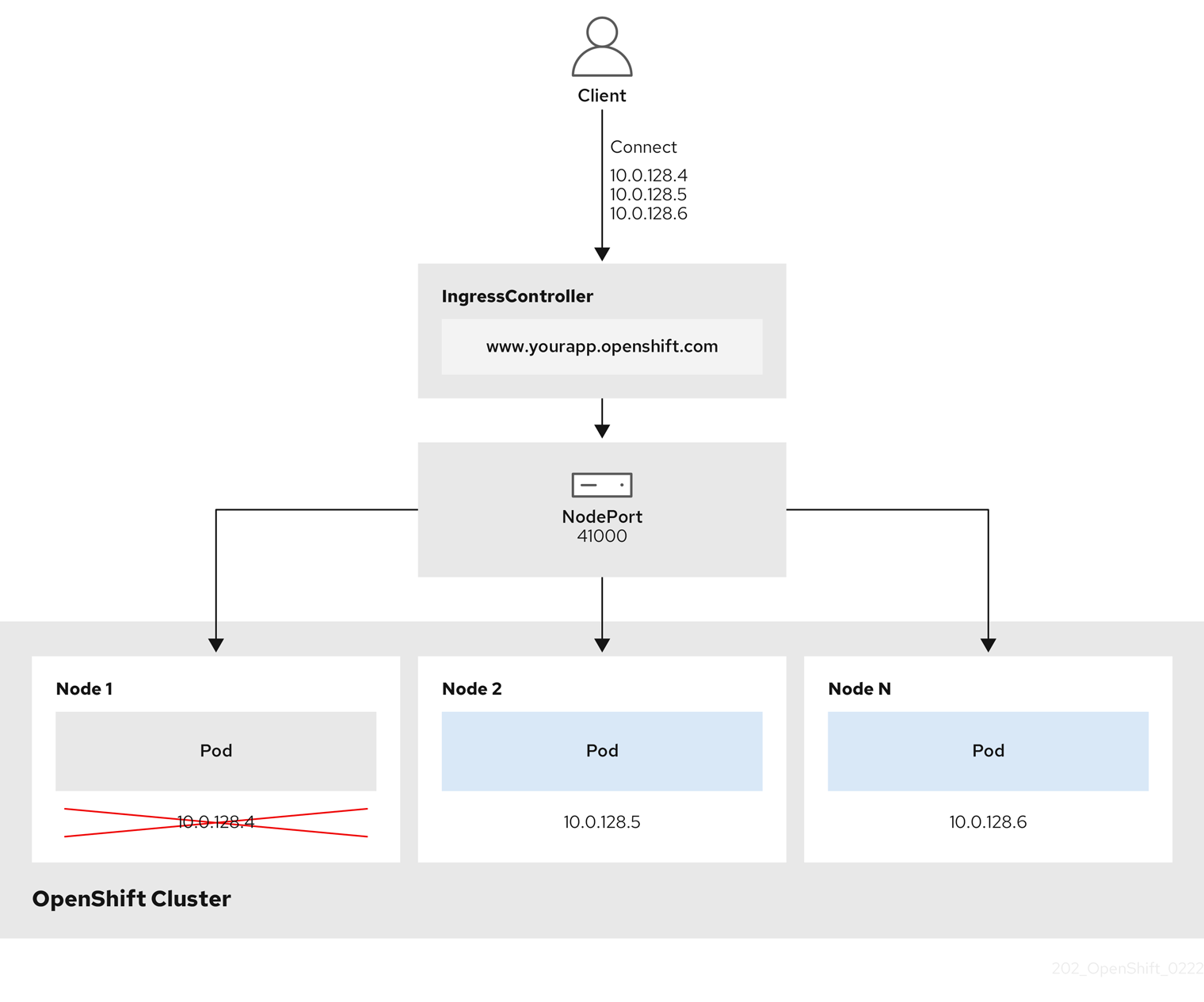
The preceding graphic shows the following concepts pertaining to OpenShift Container Platform Ingress NodePort endpoint publishing strategy:
- All the available nodes in the cluster have their own, externally accessible IP addresses. The service running in the cluster is bound to the unique NodePort for all the nodes.
-
When the client connects to a node that is down, for example, by connecting the
10.0.128.4IP address in the graphic, the node port directly connects the client to an available node that is running the service. In this scenario, no load balancing is required. As the image shows, the10.0.128.4address is down and another IP address must be used instead.
The Ingress Operator ignores any updates to .spec.ports[].nodePort fields of the service.
By default, ports are allocated automatically and you can access the port allocations for integrations. However, sometimes static port allocations are necessary to integrate with existing infrastructure which may not be easily reconfigured in response to dynamic ports. To achieve integrations with static node ports, you can update the managed service resource directly.
For more information, see the Kubernetes Services documentation on NodePort.
HostNetwork endpoint publishing strategy
The HostNetwork endpoint publishing strategy publishes the Ingress Controller on node ports where the Ingress Controller is deployed.
An Ingress controller with the HostNetwork endpoint publishing strategy can have only one pod replica per node. If you want n replicas, you must use at least n nodes where those replicas can be scheduled. Because each pod replica requests ports 80 and 443 on the node host where it is scheduled, a replica cannot be scheduled to a node if another pod on the same node is using those ports.
6.4. View the default Ingress Controller
The Ingress Operator is a core feature of OpenShift Container Platform and is enabled out of the box.
Every new OpenShift Container Platform installation has an ingresscontroller named default. It can be supplemented with additional Ingress Controllers. If the default ingresscontroller is deleted, the Ingress Operator will automatically recreate it within a minute.
Procedure
View the default Ingress Controller:
$ oc describe --namespace=openshift-ingress-operator ingresscontroller/default
6.5. View Ingress Operator status
You can view and inspect the status of your Ingress Operator.
Procedure
View your Ingress Operator status:
$ oc describe clusteroperators/ingress
6.6. View Ingress Controller logs
You can view your Ingress Controller logs.
Procedure
View your Ingress Controller logs:
$ oc logs --namespace=openshift-ingress-operator deployments/ingress-operator
6.7. View Ingress Controller status
Your can view the status of a particular Ingress Controller.
Procedure
View the status of an Ingress Controller:
$ oc describe --namespace=openshift-ingress-operator ingresscontroller/<name>
6.8. Configuring the Ingress Controller
6.8.1. Setting a custom default certificate
As an administrator, you can configure an Ingress Controller to use a custom certificate by creating a Secret resource and editing the IngressController custom resource (CR).
Prerequisites
- You must have a certificate/key pair in PEM-encoded files, where the certificate is signed by a trusted certificate authority or by a private trusted certificate authority that you configured in a custom PKI.
Your certificate meets the following requirements:
- The certificate is valid for the ingress domain.
-
The certificate uses the
subjectAltNameextension to specify a wildcard domain, such as*.apps.ocp4.example.com.
You must have an
IngressControllerCR. You may use the default one:$ oc --namespace openshift-ingress-operator get ingresscontrollersExample output
NAME AGE default 10m
If you have intermediate certificates, they must be included in the tls.crt file of the secret containing a custom default certificate. Order matters when specifying a certificate; list your intermediate certificate(s) after any server certificate(s).
Procedure
The following assumes that the custom certificate and key pair are in the tls.crt and tls.key files in the current working directory. Substitute the actual path names for tls.crt and tls.key. You also may substitute another name for custom-certs-default when creating the Secret resource and referencing it in the IngressController CR.
This action will cause the Ingress Controller to be redeployed, using a rolling deployment strategy.
Create a Secret resource containing the custom certificate in the
openshift-ingressnamespace using thetls.crtandtls.keyfiles.$ oc --namespace openshift-ingress create secret tls custom-certs-default --cert=tls.crt --key=tls.keyUpdate the IngressController CR to reference the new certificate secret:
$ oc patch --type=merge --namespace openshift-ingress-operator ingresscontrollers/default \ --patch '{"spec":{"defaultCertificate":{"name":"custom-certs-default"}}}'Verify the update was effective:
$ echo Q |\ openssl s_client -connect console-openshift-console.apps.<domain>:443 -showcerts 2>/dev/null |\ openssl x509 -noout -subject -issuer -enddatewhere:
<domain>- Specifies the base domain name for your cluster.
Example output
subject=C = US, ST = NC, L = Raleigh, O = RH, OU = OCP4, CN = *.apps.example.com issuer=C = US, ST = NC, L = Raleigh, O = RH, OU = OCP4, CN = example.com notAfter=May 10 08:32:45 2022 GMTipYou can alternatively apply the following YAML to set a custom default certificate:
apiVersion: operator.openshift.io/v1 kind: IngressController metadata: name: default namespace: openshift-ingress-operator spec: defaultCertificate: name: custom-certs-defaultThe certificate secret name should match the value used to update the CR.
Once the IngressController CR has been modified, the Ingress Operator updates the Ingress Controller’s deployment to use the custom certificate.
6.8.2. Removing a custom default certificate
As an administrator, you can remove a custom certificate that you configured an Ingress Controller to use.
Prerequisites
-
You have access to the cluster as a user with the
cluster-adminrole. -
You have installed the OpenShift CLI (
oc). - You previously configured a custom default certificate for the Ingress Controller.
Procedure
To remove the custom certificate and restore the certificate that ships with OpenShift Container Platform, enter the following command:
$ oc patch -n openshift-ingress-operator ingresscontrollers/default \ --type json -p $'- op: remove\n path: /spec/defaultCertificate'There can be a delay while the cluster reconciles the new certificate configuration.
Verification
To confirm that the original cluster certificate is restored, enter the following command:
$ echo Q | \ openssl s_client -connect console-openshift-console.apps.<domain>:443 -showcerts 2>/dev/null | \ openssl x509 -noout -subject -issuer -enddatewhere:
<domain>- Specifies the base domain name for your cluster.
Example output
subject=CN = *.apps.<domain> issuer=CN = ingress-operator@1620633373 notAfter=May 10 10:44:36 2023 GMT
6.8.3. Scaling an Ingress Controller
Manually scale an Ingress Controller to meeting routing performance or availability requirements such as the requirement to increase throughput. oc commands are used to scale the IngressController resource. The following procedure provides an example for scaling up the default IngressController.
Scaling is not an immediate action, as it takes time to create the desired number of replicas.
Procedure
View the current number of available replicas for the default
IngressController:$ oc get -n openshift-ingress-operator ingresscontrollers/default -o jsonpath='{$.status.availableReplicas}'Example output
2Scale the default
IngressControllerto the desired number of replicas using theoc patchcommand. The following example scales the defaultIngressControllerto 3 replicas:$ oc patch -n openshift-ingress-operator ingresscontroller/default --patch '{"spec":{"replicas": 3}}' --type=mergeExample output
ingresscontroller.operator.openshift.io/default patchedVerify that the default
IngressControllerscaled to the number of replicas that you specified:$ oc get -n openshift-ingress-operator ingresscontrollers/default -o jsonpath='{$.status.availableReplicas}'Example output
3TipYou can alternatively apply the following YAML to scale an Ingress Controller to three replicas:
apiVersion: operator.openshift.io/v1 kind: IngressController metadata: name: default namespace: openshift-ingress-operator spec: replicas: 31 - 1
- If you need a different amount of replicas, change the
replicasvalue.
6.8.4. Configuring Ingress access logging
You can configure the Ingress Controller to enable access logs. If you have clusters that do not receive much traffic, then you can log to a sidecar. If you have high traffic clusters, to avoid exceeding the capacity of the logging stack or to integrate with a logging infrastructure outside of OpenShift Container Platform, you can forward logs to a custom syslog endpoint. You can also specify the format for access logs.
Container logging is useful to enable access logs on low-traffic clusters when there is no existing Syslog logging infrastructure, or for short-term use while diagnosing problems with the Ingress Controller.
Syslog is needed for high-traffic clusters where access logs could exceed the OpenShift Logging stack’s capacity, or for environments where any logging solution needs to integrate with an existing Syslog logging infrastructure. The Syslog use-cases can overlap.
Prerequisites
-
Log in as a user with
cluster-adminprivileges.
Procedure
Configure Ingress access logging to a sidecar.
To configure Ingress access logging, you must specify a destination using
spec.logging.access.destination. To specify logging to a sidecar container, you must specifyContainerspec.logging.access.destination.type. The following example is an Ingress Controller definition that logs to aContainerdestination:apiVersion: operator.openshift.io/v1 kind: IngressController metadata: name: default namespace: openshift-ingress-operator spec: replicas: 2 logging: access: destination: type: ContainerWhen you configure the Ingress Controller to log to a sidecar, the operator creates a container named
logsinside the Ingress Controller Pod:$ oc -n openshift-ingress logs deployment.apps/router-default -c logsExample output
2020-05-11T19:11:50.135710+00:00 router-default-57dfc6cd95-bpmk6 router-default-57dfc6cd95-bpmk6 haproxy[108]: 174.19.21.82:39654 [11/May/2020:19:11:50.133] public be_http:hello-openshift:hello-openshift/pod:hello-openshift:hello-openshift:10.128.2.12:8080 0/0/1/0/1 200 142 - - --NI 1/1/0/0/0 0/0 "GET / HTTP/1.1"
Configure Ingress access logging to a Syslog endpoint.
To configure Ingress access logging, you must specify a destination using
spec.logging.access.destination. To specify logging to a Syslog endpoint destination, you must specifySyslogforspec.logging.access.destination.type. If the destination type isSyslog, you must also specify a destination endpoint usingspec.logging.access.destination.syslog.endpointand you can specify a facility usingspec.logging.access.destination.syslog.facility. The following example is an Ingress Controller definition that logs to aSyslogdestination:apiVersion: operator.openshift.io/v1 kind: IngressController metadata: name: default namespace: openshift-ingress-operator spec: replicas: 2 logging: access: destination: type: Syslog syslog: address: 1.2.3.4 port: 10514NoteThe
syslogdestination port must be UDP.
Configure Ingress access logging with a specific log format.
You can specify
spec.logging.access.httpLogFormatto customize the log format. The following example is an Ingress Controller definition that logs to asyslogendpoint with IP address 1.2.3.4 and port 10514:apiVersion: operator.openshift.io/v1 kind: IngressController metadata: name: default namespace: openshift-ingress-operator spec: replicas: 2 logging: access: destination: type: Syslog syslog: address: 1.2.3.4 port: 10514 httpLogFormat: '%ci:%cp [%t] %ft %b/%s %B %bq %HM %HU %HV'
Disable Ingress access logging.
To disable Ingress access logging, leave
spec.loggingorspec.logging.accessempty:apiVersion: operator.openshift.io/v1 kind: IngressController metadata: name: default namespace: openshift-ingress-operator spec: replicas: 2 logging: access: null
6.8.5. Setting Ingress Controller thread count
A cluster administrator can set the thread count to increase the amount of incoming connections a cluster can handle. You can patch an existing Ingress Controller to increase the amount of threads.
Prerequisites
- The following assumes that you already created an Ingress Controller.
Procedure
Update the Ingress Controller to increase the number of threads:
$ oc -n openshift-ingress-operator patch ingresscontroller/default --type=merge -p '{"spec":{"tuningOptions": {"threadCount": 8}}}'NoteIf you have a node that is capable of running large amounts of resources, you can configure
spec.nodePlacement.nodeSelectorwith labels that match the capacity of the intended node, and configurespec.tuningOptions.threadCountto an appropriately high value.
6.8.6. Ingress Controller sharding
As the primary mechanism for traffic to enter the cluster, the demands on the Ingress Controller, or router, can be significant. As a cluster administrator, you can shard the routes to:
- Balance Ingress Controllers, or routers, with several routes to speed up responses to changes.
- Allocate certain routes to have different reliability guarantees than other routes.
- Allow certain Ingress Controllers to have different policies defined.
- Allow only specific routes to use additional features.
- Expose different routes on different addresses so that internal and external users can see different routes, for example.
Ingress Controller can use either route labels or namespace labels as a sharding method.
6.8.6.1. Configuring Ingress Controller sharding by using route labels
Ingress Controller sharding by using route labels means that the Ingress Controller serves any route in any namespace that is selected by the route selector.
Ingress Controller sharding is useful when balancing incoming traffic load among a set of Ingress Controllers and when isolating traffic to a specific Ingress Controller. For example, company A goes to one Ingress Controller and company B to another.
Procedure
Edit the
router-internal.yamlfile:# cat router-internal.yaml apiVersion: v1 items: - apiVersion: operator.openshift.io/v1 kind: IngressController metadata: name: sharded namespace: openshift-ingress-operator spec: domain: <apps-sharded.basedomain.example.net> nodePlacement: nodeSelector: matchLabels: node-role.kubernetes.io/worker: "" routeSelector: matchLabels: type: sharded status: {} kind: List metadata: resourceVersion: "" selfLink: ""Apply the Ingress Controller
router-internal.yamlfile:# oc apply -f router-internal.yamlThe Ingress Controller selects routes in any namespace that have the label
type: sharded.
6.8.6.2. Configuring Ingress Controller sharding by using namespace labels
Ingress Controller sharding by using namespace labels means that the Ingress Controller serves any route in any namespace that is selected by the namespace selector.
Ingress Controller sharding is useful when balancing incoming traffic load among a set of Ingress Controllers and when isolating traffic to a specific Ingress Controller. For example, company A goes to one Ingress Controller and company B to another.
If you deploy the Keepalived Ingress VIP, do not deploy a non-default Ingress Controller with value HostNetwork for the endpointPublishingStrategy parameter. Doing so might cause issues. Use value NodePort instead of HostNetwork for endpointPublishingStrategy.
Procedure
Edit the
router-internal.yamlfile:# cat router-internal.yamlExample output
apiVersion: v1 items: - apiVersion: operator.openshift.io/v1 kind: IngressController metadata: name: sharded namespace: openshift-ingress-operator spec: domain: <apps-sharded.basedomain.example.net> nodePlacement: nodeSelector: matchLabels: node-role.kubernetes.io/worker: "" namespaceSelector: matchLabels: type: sharded status: {} kind: List metadata: resourceVersion: "" selfLink: ""Apply the Ingress Controller
router-internal.yamlfile:# oc apply -f router-internal.yamlThe Ingress Controller selects routes in any namespace that is selected by the namespace selector that have the label
type: sharded.
6.8.7. Configuring an Ingress Controller to use an internal load balancer
When creating an Ingress Controller on cloud platforms, the Ingress Controller is published by a public cloud load balancer by default. As an administrator, you can create an Ingress Controller that uses an internal cloud load balancer.
If your cloud provider is Microsoft Azure, you must have at least one public load balancer that points to your nodes. If you do not, all of your nodes will lose egress connectivity to the internet.
If you want to change the scope for an IngressController object, you must delete and then recreate that IngressController object. You cannot change the .spec.endpointPublishingStrategy.loadBalancer.scope parameter after the custom resource (CR) is created.
Figure 6.2. Diagram of LoadBalancer
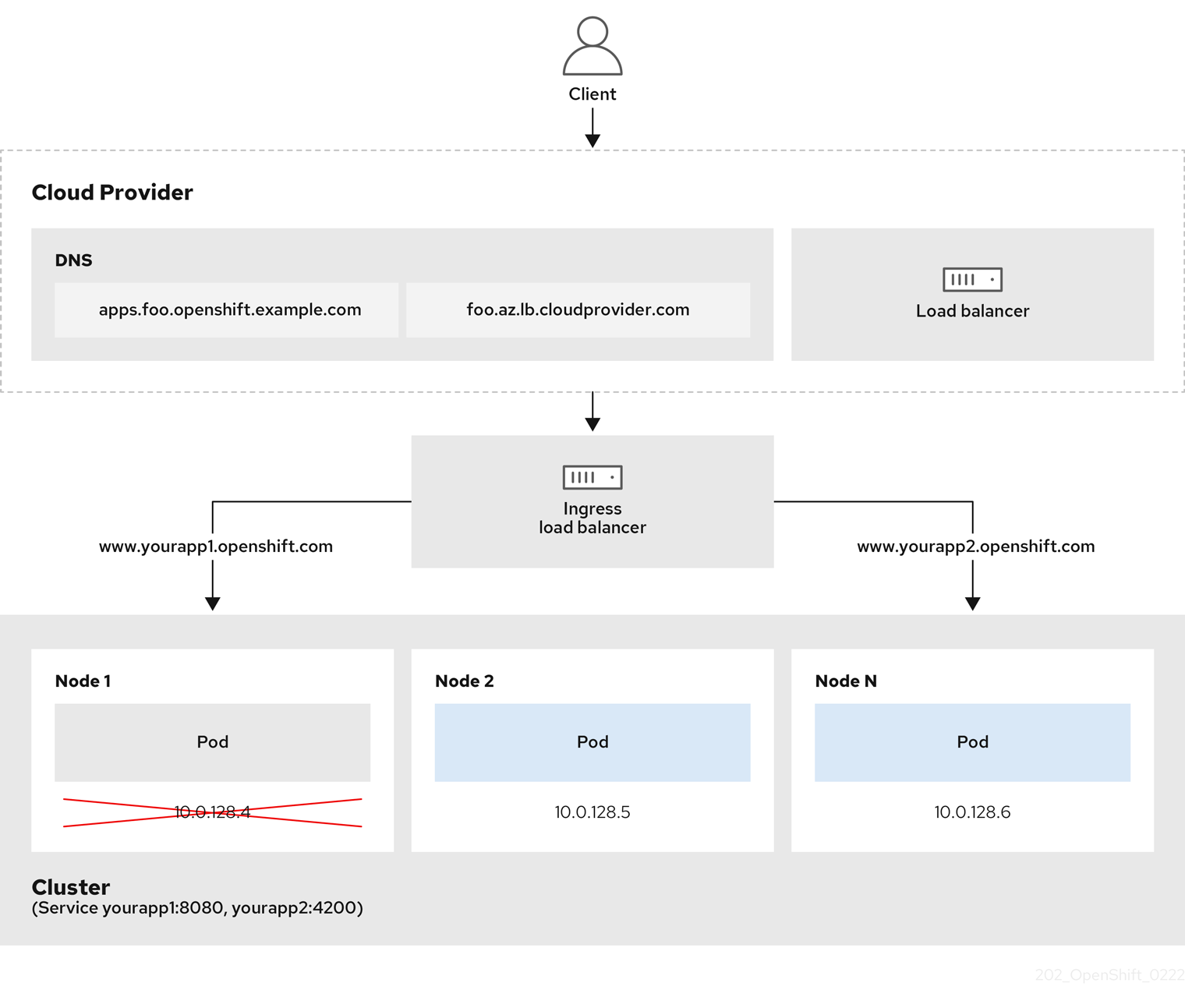
The preceding graphic shows the following concepts pertaining to OpenShift Container Platform Ingress LoadBalancerService endpoint publishing strategy:
- You can load load balance externally, using the cloud provider load balancer, or internally, using the OpenShift Ingress Controller Load Balancer.
- You can use the single IP address of the load balancer and more familiar ports, such as 8080 and 4200 as shown on the cluster depicted in the graphic.
- Traffic from the external load balancer is directed at the pods, and managed by the load balancer, as depicted in the instance of a down node. See the Kubernetes Services documentation for implementation details.
Prerequisites
-
Install the OpenShift CLI (
oc). -
Log in as a user with
cluster-adminprivileges.
Procedure
Create an
IngressControllercustom resource (CR) in a file named<name>-ingress-controller.yaml, such as in the following example:apiVersion: operator.openshift.io/v1 kind: IngressController metadata: namespace: openshift-ingress-operator name: <name>1 spec: domain: <domain>2 endpointPublishingStrategy: type: LoadBalancerService loadBalancer: scope: Internal3 Create the Ingress Controller defined in the previous step by running the following command:
$ oc create -f <name>-ingress-controller.yaml1 - 1
- Replace
<name>with the name of theIngressControllerobject.
Optional: Confirm that the Ingress Controller was created by running the following command:
$ oc --all-namespaces=true get ingresscontrollers
6.8.8. Configuring global access for an Ingress Controller on GCP
An Ingress Controller created on GCP with an internal load balancer generates an internal IP address for the service. A cluster administrator can specify the global access option, which enables clients in any region within the same VPC network and compute region as the load balancer, to reach the workloads running on your cluster.
For more information, see the GCP documentation for global access.
Prerequisites
- You deployed an OpenShift Container Platform cluster on GCP infrastructure.
- You configured an Ingress Controller to use an internal load balancer.
-
You installed the OpenShift CLI (
oc).
Procedure
Configure the Ingress Controller resource to allow global access.
NoteYou can also create an Ingress Controller and specify the global access option.
Configure the Ingress Controller resource:
$ oc -n openshift-ingress-operator edit ingresscontroller/defaultEdit the YAML file:
Sample
clientAccessconfiguration toGlobalspec: endpointPublishingStrategy: loadBalancer: providerParameters: gcp: clientAccess: Global1 type: GCP scope: Internal type: LoadBalancerService- 1
- Set
gcp.clientAccesstoGlobal.
- Save the file to apply the changes.
Run the following command to verify that the service allows global access:
$ oc -n openshift-ingress edit svc/router-default -o yamlThe output shows that global access is enabled for GCP with the annotation,
networking.gke.io/internal-load-balancer-allow-global-access.
6.8.9. Configuring the default Ingress Controller for your cluster to be internal
You can configure the default Ingress Controller for your cluster to be internal by deleting and recreating it.
If your cloud provider is Microsoft Azure, you must have at least one public load balancer that points to your nodes. If you do not, all of your nodes will lose egress connectivity to the internet.
If you want to change the scope for an IngressController object, you must delete and then recreate that IngressController object. You cannot change the .spec.endpointPublishingStrategy.loadBalancer.scope parameter after the custom resource (CR) is created.
Prerequisites
-
Install the OpenShift CLI (
oc). -
Log in as a user with
cluster-adminprivileges.
Procedure
Configure the
defaultIngress Controller for your cluster to be internal by deleting and recreating it.$ oc replace --force --wait --filename - <<EOF apiVersion: operator.openshift.io/v1 kind: IngressController metadata: namespace: openshift-ingress-operator name: default spec: endpointPublishingStrategy: type: LoadBalancerService loadBalancer: scope: Internal EOF
6.8.10. Configuring the route admission policy
Administrators and application developers can run applications in multiple namespaces with the same domain name. This is for organizations where multiple teams develop microservices that are exposed on the same hostname.
Allowing claims across namespaces should only be enabled for clusters with trust between namespaces, otherwise a malicious user could take over a hostname. For this reason, the default admission policy disallows hostname claims across namespaces.
Prerequisites
- Cluster administrator privileges.
Procedure
Edit the
.spec.routeAdmissionfield of theingresscontrollerresource variable using the following command:$ oc -n openshift-ingress-operator patch ingresscontroller/default --patch '{"spec":{"routeAdmission":{"namespaceOwnership":"InterNamespaceAllowed"}}}' --type=mergeSample Ingress Controller configuration
spec: routeAdmission: namespaceOwnership: InterNamespaceAllowed ...TipYou can alternatively apply the following YAML to configure the route admission policy:
apiVersion: operator.openshift.io/v1 kind: IngressController metadata: name: default namespace: openshift-ingress-operator spec: routeAdmission: namespaceOwnership: InterNamespaceAllowed
6.8.11. Using wildcard routes
The HAProxy Ingress Controller has support for wildcard routes. The Ingress Operator uses wildcardPolicy to configure the ROUTER_ALLOW_WILDCARD_ROUTES environment variable of the Ingress Controller.
The default behavior of the Ingress Controller is to admit routes with a wildcard policy of None, which is backwards compatible with existing IngressController resources.
Procedure
Configure the wildcard policy.
Use the following command to edit the
IngressControllerresource:$ oc edit IngressControllerUnder
spec, set thewildcardPolicyfield toWildcardsDisallowedorWildcardsAllowed:spec: routeAdmission: wildcardPolicy: WildcardsDisallowed # or WildcardsAllowed
6.8.12. Using X-Forwarded headers
You configure the HAProxy Ingress Controller to specify a policy for how to handle HTTP headers including Forwarded and X-Forwarded-For. The Ingress Operator uses the HTTPHeaders field to configure the ROUTER_SET_FORWARDED_HEADERS environment variable of the Ingress Controller.
Procedure
Configure the
HTTPHeadersfield for the Ingress Controller.Use the following command to edit the
IngressControllerresource:$ oc edit IngressControllerUnder
spec, set theHTTPHeaderspolicy field toAppend,Replace,IfNone, orNever:apiVersion: operator.openshift.io/v1 kind: IngressController metadata: name: default namespace: openshift-ingress-operator spec: httpHeaders: forwardedHeaderPolicy: Append
Example use cases
As a cluster administrator, you can:
Configure an external proxy that injects the
X-Forwarded-Forheader into each request before forwarding it to an Ingress Controller.To configure the Ingress Controller to pass the header through unmodified, you specify the
neverpolicy. The Ingress Controller then never sets the headers, and applications receive only the headers that the external proxy provides.Configure the Ingress Controller to pass the
X-Forwarded-Forheader that your external proxy sets on external cluster requests through unmodified.To configure the Ingress Controller to set the
X-Forwarded-Forheader on internal cluster requests, which do not go through the external proxy, specify theif-nonepolicy. If an HTTP request already has the header set through the external proxy, then the Ingress Controller preserves it. If the header is absent because the request did not come through the proxy, then the Ingress Controller adds the header.
As an application developer, you can:
Configure an application-specific external proxy that injects the
X-Forwarded-Forheader.To configure an Ingress Controller to pass the header through unmodified for an application’s Route, without affecting the policy for other Routes, add an annotation
haproxy.router.openshift.io/set-forwarded-headers: if-noneorhaproxy.router.openshift.io/set-forwarded-headers: neveron the Route for the application.NoteYou can set the
haproxy.router.openshift.io/set-forwarded-headersannotation on a per route basis, independent from the globally set value for the Ingress Controller.
6.8.13. Enabling HTTP/2 Ingress connectivity
You can enable transparent end-to-end HTTP/2 connectivity in HAProxy. It allows application owners to make use of HTTP/2 protocol capabilities, including single connection, header compression, binary streams, and more.
You can enable HTTP/2 connectivity for an individual Ingress Controller or for the entire cluster.
To enable the use of HTTP/2 for the connection from the client to HAProxy, a route must specify a custom certificate. A route that uses the default certificate cannot use HTTP/2. This restriction is necessary to avoid problems from connection coalescing, where the client re-uses a connection for different routes that use the same certificate.
The connection from HAProxy to the application pod can use HTTP/2 only for re-encrypt routes and not for edge-terminated or insecure routes. This restriction is because HAProxy uses Application-Level Protocol Negotiation (ALPN), which is a TLS extension, to negotiate the use of HTTP/2 with the back-end. The implication is that end-to-end HTTP/2 is possible with passthrough and re-encrypt and not with insecure or edge-terminated routes.
Using WebSockets with a re-encrypt route and with HTTP/2 enabled on an Ingress Controller requires WebSocket support over HTTP/2. WebSockets over HTTP/2 is a feature of HAProxy 2.4, which is unsupported in OpenShift Container Platform at this time.
For non-passthrough routes, the Ingress Controller negotiates its connection to the application independently of the connection from the client. This means a client may connect to the Ingress Controller and negotiate HTTP/1.1, and the Ingress Controller may then connect to the application, negotiate HTTP/2, and forward the request from the client HTTP/1.1 connection using the HTTP/2 connection to the application. This poses a problem if the client subsequently tries to upgrade its connection from HTTP/1.1 to the WebSocket protocol, because the Ingress Controller cannot forward WebSocket to HTTP/2 and cannot upgrade its HTTP/2 connection to WebSocket. Consequently, if you have an application that is intended to accept WebSocket connections, it must not allow negotiating the HTTP/2 protocol or else clients will fail to upgrade to the WebSocket protocol.
Procedure
Enable HTTP/2 on a single Ingress Controller.
To enable HTTP/2 on an Ingress Controller, enter the
oc annotatecommand:$ oc -n openshift-ingress-operator annotate ingresscontrollers/<ingresscontroller_name> ingress.operator.openshift.io/default-enable-http2=trueReplace
<ingresscontroller_name>with the name of the Ingress Controller to annotate.
Enable HTTP/2 on the entire cluster.
To enable HTTP/2 for the entire cluster, enter the
oc annotatecommand:$ oc annotate ingresses.config/cluster ingress.operator.openshift.io/default-enable-http2=trueTipYou can alternatively apply the following YAML to add the annotation:
apiVersion: config.openshift.io/v1 kind: Ingress metadata: name: cluster annotations: ingress.operator.openshift.io/default-enable-http2: "true"
6.8.14. Configuring the PROXY protocol for an Ingress Controller
A cluster administrator can configure the PROXY protocol when an Ingress Controller uses either the HostNetwork or NodePortService endpoint publishing strategy types. The PROXY protocol enables the load balancer to preserve the original client addresses for connections that the Ingress Controller receives. The original client addresses are useful for logging, filtering, and injecting HTTP headers. In the default configuration, the connections that the Ingress Controller receives only contain the source address that is associated with the load balancer.
This feature is not supported in cloud deployments. This restriction is because when OpenShift Container Platform runs in a cloud platform, and an IngressController specifies that a service load balancer should be used, the Ingress Operator configures the load balancer service and enables the PROXY protocol based on the platform requirement for preserving source addresses.
You must configure both OpenShift Container Platform and the external load balancer to either use the PROXY protocol or to use TCP.
The PROXY protocol is unsupported for the default Ingress Controller with installer-provisioned clusters on non-cloud platforms that use a Keepalived Ingress VIP.
Prerequisites
- You created an Ingress Controller.
Procedure
Edit the Ingress Controller resource:
$ oc -n openshift-ingress-operator edit ingresscontroller/defaultSet the PROXY configuration:
If your Ingress Controller uses the hostNetwork endpoint publishing strategy type, set the
spec.endpointPublishingStrategy.hostNetwork.protocolsubfield toPROXY:Sample
hostNetworkconfiguration toPROXYspec: endpointPublishingStrategy: hostNetwork: protocol: PROXY type: HostNetworkIf your Ingress Controller uses the NodePortService endpoint publishing strategy type, set the
spec.endpointPublishingStrategy.nodePort.protocolsubfield toPROXY:Sample
nodePortconfiguration toPROXYspec: endpointPublishingStrategy: nodePort: protocol: PROXY type: NodePortService
6.8.15. Specifying an alternative cluster domain using the appsDomain option
As a cluster administrator, you can specify an alternative to the default cluster domain for user-created routes by configuring the appsDomain field. The appsDomain field is an optional domain for OpenShift Container Platform to use instead of the default, which is specified in the domain field. If you specify an alternative domain, it overrides the default cluster domain for the purpose of determining the default host for a new route.
For example, you can use the DNS domain for your company as the default domain for routes and ingresses for applications running on your cluster.
Prerequisites
- You deployed an OpenShift Container Platform cluster.
-
You installed the
occommand line interface.
Procedure
Configure the
appsDomainfield by specifying an alternative default domain for user-created routes.Edit the ingress
clusterresource:$ oc edit ingresses.config/cluster -o yamlEdit the YAML file:
Sample
appsDomainconfiguration totest.example.comapiVersion: config.openshift.io/v1 kind: Ingress metadata: name: cluster spec: domain: apps.example.com1 appsDomain: <test.example.com>2
Verify that an existing route contains the domain name specified in the
appsDomainfield by exposing the route and verifying the route domain change:NoteWait for the
openshift-apiserverfinish rolling updates before exposing the route.Expose the route:
$ oc expose service hello-openshift route.route.openshift.io/hello-openshift exposedExample output:
$ oc get routes NAME HOST/PORT PATH SERVICES PORT TERMINATION WILDCARD hello-openshift hello_openshift-<my_project>.test.example.com hello-openshift 8080-tcp None
6.8.16. Converting HTTP header case
HAProxy 2.2 lowercases HTTP header names by default, for example, changing Host: xyz.com to host: xyz.com. If legacy applications are sensitive to the capitalization of HTTP header names, use the Ingress Controller spec.httpHeaders.headerNameCaseAdjustments API field for a solution to accommodate legacy applications until they can be fixed.
Because OpenShift Container Platform 4.8 includes HAProxy 2.2, make sure to add the necessary configuration by using spec.httpHeaders.headerNameCaseAdjustments before upgrading.
Prerequisites
-
You have installed the OpenShift CLI (
oc). -
You have access to the cluster as a user with the
cluster-adminrole.
Procedure
As a cluster administrator, you can convert the HTTP header case by entering the oc patch command or by setting the HeaderNameCaseAdjustments field in the Ingress Controller YAML file.
Specify an HTTP header to be capitalized by entering the
oc patchcommand.Enter the
oc patchcommand to change the HTTPhostheader toHost:$ oc -n openshift-ingress-operator patch ingresscontrollers/default --type=merge --patch='{"spec":{"httpHeaders":{"headerNameCaseAdjustments":["Host"]}}}'Annotate the route of the application:
$ oc annotate routes/my-application haproxy.router.openshift.io/h1-adjust-case=trueThe Ingress Controller then adjusts the
hostrequest header as specified.
Specify adjustments using the
HeaderNameCaseAdjustmentsfield by configuring the Ingress Controller YAML file.The following example Ingress Controller YAML adjusts the
hostheader toHostfor HTTP/1 requests to appropriately annotated routes:Example Ingress Controller YAML
apiVersion: operator.openshift.io/v1 kind: IngressController metadata: name: default namespace: openshift-ingress-operator spec: httpHeaders: headerNameCaseAdjustments: - HostThe following example route enables HTTP response header name case adjustments using the
haproxy.router.openshift.io/h1-adjust-caseannotation:Example route YAML
apiVersion: route.openshift.io/v1 kind: Route metadata: annotations: haproxy.router.openshift.io/h1-adjust-case: true1 name: my-application namespace: my-application spec: to: kind: Service name: my-application- 1
- Set
haproxy.router.openshift.io/h1-adjust-caseto true.
Chapter 7. Verifying connectivity to an endpoint
The Cluster Network Operator (CNO) runs a controller, the connectivity check controller, that performs a connection health check between resources within your cluster. By reviewing the results of the health checks, you can diagnose connection problems or eliminate network connectivity as the cause of an issue that you are investigating.
7.1. Connection health checks performed
To verify that cluster resources are reachable, a TCP connection is made to each of the following cluster API services:
- Kubernetes API server service
- Kubernetes API server endpoints
- OpenShift API server service
- OpenShift API server endpoints
- Load balancers
To verify that services and service endpoints are reachable on every node in the cluster, a TCP connection is made to each of the following targets:
- Health check target service
- Health check target endpoints
7.2. Implementation of connection health checks
The connectivity check controller orchestrates connection verification checks in your cluster. The results for the connection tests are stored in PodNetworkConnectivity objects in the openshift-network-diagnostics namespace. Connection tests are performed every minute in parallel.
The Cluster Network Operator (CNO) deploys several resources to the cluster to send and receive connectivity health checks:
- Health check source
-
This program deploys in a single pod replica set managed by a
Deploymentobject. The program consumesPodNetworkConnectivityobjects and connects to thespec.targetEndpointspecified in each object. - Health check target
- A pod deployed as part of a daemon set on every node in the cluster. The pod listens for inbound health checks. The presence of this pod on every node allows for the testing of connectivity to each node.
7.3. PodNetworkConnectivityCheck object fields
The PodNetworkConnectivityCheck object fields are described in the following tables.
| Field | Type | Description |
|---|---|---|
|
|
|
The name of the object in the following format:
|
|
|
|
The namespace that the object is associated with. This value is always |
|
|
|
The name of the pod where the connection check originates, such as |
|
|
|
The target of the connection check, such as |
|
|
| Configuration for the TLS certificate to use. |
|
|
| The name of the TLS certificate used, if any. The default value is an empty string. |
|
|
| An object representing the condition of the connection test and logs of recent connection successes and failures. |
|
|
| The latest status of the connection check and any previous statuses. |
|
|
| Connection test logs from unsuccessful attempts. |
|
|
| Connect test logs covering the time periods of any outages. |
|
|
| Connection test logs from successful attempts. |
The following table describes the fields for objects in the status.conditions array:
| Field | Type | Description |
|---|---|---|
|
|
| The time that the condition of the connection transitioned from one status to another. |
|
|
| The details about last transition in a human readable format. |
|
|
| The last status of the transition in a machine readable format. |
|
|
| The status of the condition. |
|
|
| The type of the condition. |
The following table describes the fields for objects in the status.conditions array:
| Field | Type | Description |
|---|---|---|
|
|
| The timestamp from when the connection failure is resolved. |
|
|
| Connection log entries, including the log entry related to the successful end of the outage. |
|
|
| A summary of outage details in a human readable format. |
|
|
| The timestamp from when the connection failure is first detected. |
|
|
| Connection log entries, including the original failure. |
Connection log fields
The fields for a connection log entry are described in the following table. The object is used in the following fields:
-
status.failures[] -
status.successes[] -
status.outages[].startLogs[] -
status.outages[].endLogs[]
| Field | Type | Description |
|---|---|---|
|
|
| Records the duration of the action. |
|
|
| Provides the status in a human readable format. |
|
|
|
Provides the reason for status in a machine readable format. The value is one of |
|
|
| Indicates if the log entry is a success or failure. |
|
|
| The start time of connection check. |
7.4. Verifying network connectivity for an endpoint
As a cluster administrator, you can verify the connectivity of an endpoint, such as an API server, load balancer, service, or pod.
Prerequisites
-
Install the OpenShift CLI (
oc). -
Access to the cluster as a user with the
cluster-adminrole.
Procedure
To list the current
PodNetworkConnectivityCheckobjects, enter the following command:$ oc get podnetworkconnectivitycheck -n openshift-network-diagnosticsExample output
NAME AGE network-check-source-ci-ln-x5sv9rb-f76d1-4rzrp-worker-b-6xdmh-to-kubernetes-apiserver-endpoint-ci-ln-x5sv9rb-f76d1-4rzrp-master-0 75m network-check-source-ci-ln-x5sv9rb-f76d1-4rzrp-worker-b-6xdmh-to-kubernetes-apiserver-endpoint-ci-ln-x5sv9rb-f76d1-4rzrp-master-1 73m network-check-source-ci-ln-x5sv9rb-f76d1-4rzrp-worker-b-6xdmh-to-kubernetes-apiserver-endpoint-ci-ln-x5sv9rb-f76d1-4rzrp-master-2 75m network-check-source-ci-ln-x5sv9rb-f76d1-4rzrp-worker-b-6xdmh-to-kubernetes-apiserver-service-cluster 75m network-check-source-ci-ln-x5sv9rb-f76d1-4rzrp-worker-b-6xdmh-to-kubernetes-default-service-cluster 75m network-check-source-ci-ln-x5sv9rb-f76d1-4rzrp-worker-b-6xdmh-to-load-balancer-api-external 75m network-check-source-ci-ln-x5sv9rb-f76d1-4rzrp-worker-b-6xdmh-to-load-balancer-api-internal 75m network-check-source-ci-ln-x5sv9rb-f76d1-4rzrp-worker-b-6xdmh-to-network-check-target-ci-ln-x5sv9rb-f76d1-4rzrp-master-0 75m network-check-source-ci-ln-x5sv9rb-f76d1-4rzrp-worker-b-6xdmh-to-network-check-target-ci-ln-x5sv9rb-f76d1-4rzrp-master-1 75m network-check-source-ci-ln-x5sv9rb-f76d1-4rzrp-worker-b-6xdmh-to-network-check-target-ci-ln-x5sv9rb-f76d1-4rzrp-master-2 75m network-check-source-ci-ln-x5sv9rb-f76d1-4rzrp-worker-b-6xdmh-to-network-check-target-ci-ln-x5sv9rb-f76d1-4rzrp-worker-b-6xdmh 74m network-check-source-ci-ln-x5sv9rb-f76d1-4rzrp-worker-b-6xdmh-to-network-check-target-ci-ln-x5sv9rb-f76d1-4rzrp-worker-c-n8mbf 74m network-check-source-ci-ln-x5sv9rb-f76d1-4rzrp-worker-b-6xdmh-to-network-check-target-ci-ln-x5sv9rb-f76d1-4rzrp-worker-d-4hnrz 74m network-check-source-ci-ln-x5sv9rb-f76d1-4rzrp-worker-b-6xdmh-to-network-check-target-service-cluster 75m network-check-source-ci-ln-x5sv9rb-f76d1-4rzrp-worker-b-6xdmh-to-openshift-apiserver-endpoint-ci-ln-x5sv9rb-f76d1-4rzrp-master-0 75m network-check-source-ci-ln-x5sv9rb-f76d1-4rzrp-worker-b-6xdmh-to-openshift-apiserver-endpoint-ci-ln-x5sv9rb-f76d1-4rzrp-master-1 75m network-check-source-ci-ln-x5sv9rb-f76d1-4rzrp-worker-b-6xdmh-to-openshift-apiserver-endpoint-ci-ln-x5sv9rb-f76d1-4rzrp-master-2 74m network-check-source-ci-ln-x5sv9rb-f76d1-4rzrp-worker-b-6xdmh-to-openshift-apiserver-service-cluster 75mView the connection test logs:
- From the output of the previous command, identify the endpoint that you want to review the connectivity logs for.
To view the object, enter the following command:
$ oc get podnetworkconnectivitycheck <name> \ -n openshift-network-diagnostics -o yamlwhere
<name>specifies the name of thePodNetworkConnectivityCheckobject.Example output
apiVersion: controlplane.operator.openshift.io/v1alpha1 kind: PodNetworkConnectivityCheck metadata: name: network-check-source-ci-ln-x5sv9rb-f76d1-4rzrp-worker-b-6xdmh-to-kubernetes-apiserver-endpoint-ci-ln-x5sv9rb-f76d1-4rzrp-master-0 namespace: openshift-network-diagnostics ... spec: sourcePod: network-check-source-7c88f6d9f-hmg2f targetEndpoint: 10.0.0.4:6443 tlsClientCert: name: "" status: conditions: - lastTransitionTime: "2021-01-13T20:11:34Z" message: 'kubernetes-apiserver-endpoint-ci-ln-x5sv9rb-f76d1-4rzrp-master-0: tcp connection to 10.0.0.4:6443 succeeded' reason: TCPConnectSuccess status: "True" type: Reachable failures: - latency: 2.241775ms message: 'kubernetes-apiserver-endpoint-ci-ln-x5sv9rb-f76d1-4rzrp-master-0: failed to establish a TCP connection to 10.0.0.4:6443: dial tcp 10.0.0.4:6443: connect: connection refused' reason: TCPConnectError success: false time: "2021-01-13T20:10:34Z" - latency: 2.582129ms message: 'kubernetes-apiserver-endpoint-ci-ln-x5sv9rb-f76d1-4rzrp-master-0: failed to establish a TCP connection to 10.0.0.4:6443: dial tcp 10.0.0.4:6443: connect: connection refused' reason: TCPConnectError success: false time: "2021-01-13T20:09:34Z" - latency: 3.483578ms message: 'kubernetes-apiserver-endpoint-ci-ln-x5sv9rb-f76d1-4rzrp-master-0: failed to establish a TCP connection to 10.0.0.4:6443: dial tcp 10.0.0.4:6443: connect: connection refused' reason: TCPConnectError success: false time: "2021-01-13T20:08:34Z" outages: - end: "2021-01-13T20:11:34Z" endLogs: - latency: 2.032018ms message: 'kubernetes-apiserver-endpoint-ci-ln-x5sv9rb-f76d1-4rzrp-master-0: tcp connection to 10.0.0.4:6443 succeeded' reason: TCPConnect success: true time: "2021-01-13T20:11:34Z" - latency: 2.241775ms message: 'kubernetes-apiserver-endpoint-ci-ln-x5sv9rb-f76d1-4rzrp-master-0: failed to establish a TCP connection to 10.0.0.4:6443: dial tcp 10.0.0.4:6443: connect: connection refused' reason: TCPConnectError success: false time: "2021-01-13T20:10:34Z" - latency: 2.582129ms message: 'kubernetes-apiserver-endpoint-ci-ln-x5sv9rb-f76d1-4rzrp-master-0: failed to establish a TCP connection to 10.0.0.4:6443: dial tcp 10.0.0.4:6443: connect: connection refused' reason: TCPConnectError success: false time: "2021-01-13T20:09:34Z" - latency: 3.483578ms message: 'kubernetes-apiserver-endpoint-ci-ln-x5sv9rb-f76d1-4rzrp-master-0: failed to establish a TCP connection to 10.0.0.4:6443: dial tcp 10.0.0.4:6443: connect: connection refused' reason: TCPConnectError success: false time: "2021-01-13T20:08:34Z" message: Connectivity restored after 2m59.999789186s start: "2021-01-13T20:08:34Z" startLogs: - latency: 3.483578ms message: 'kubernetes-apiserver-endpoint-ci-ln-x5sv9rb-f76d1-4rzrp-master-0: failed to establish a TCP connection to 10.0.0.4:6443: dial tcp 10.0.0.4:6443: connect: connection refused' reason: TCPConnectError success: false time: "2021-01-13T20:08:34Z" successes: - latency: 2.845865ms message: 'kubernetes-apiserver-endpoint-ci-ln-x5sv9rb-f76d1-4rzrp-master-0: tcp connection to 10.0.0.4:6443 succeeded' reason: TCPConnect success: true time: "2021-01-13T21:14:34Z" - latency: 2.926345ms message: 'kubernetes-apiserver-endpoint-ci-ln-x5sv9rb-f76d1-4rzrp-master-0: tcp connection to 10.0.0.4:6443 succeeded' reason: TCPConnect success: true time: "2021-01-13T21:13:34Z" - latency: 2.895796ms message: 'kubernetes-apiserver-endpoint-ci-ln-x5sv9rb-f76d1-4rzrp-master-0: tcp connection to 10.0.0.4:6443 succeeded' reason: TCPConnect success: true time: "2021-01-13T21:12:34Z" - latency: 2.696844ms message: 'kubernetes-apiserver-endpoint-ci-ln-x5sv9rb-f76d1-4rzrp-master-0: tcp connection to 10.0.0.4:6443 succeeded' reason: TCPConnect success: true time: "2021-01-13T21:11:34Z" - latency: 1.502064ms message: 'kubernetes-apiserver-endpoint-ci-ln-x5sv9rb-f76d1-4rzrp-master-0: tcp connection to 10.0.0.4:6443 succeeded' reason: TCPConnect success: true time: "2021-01-13T21:10:34Z" - latency: 1.388857ms message: 'kubernetes-apiserver-endpoint-ci-ln-x5sv9rb-f76d1-4rzrp-master-0: tcp connection to 10.0.0.4:6443 succeeded' reason: TCPConnect success: true time: "2021-01-13T21:09:34Z" - latency: 1.906383ms message: 'kubernetes-apiserver-endpoint-ci-ln-x5sv9rb-f76d1-4rzrp-master-0: tcp connection to 10.0.0.4:6443 succeeded' reason: TCPConnect success: true time: "2021-01-13T21:08:34Z" - latency: 2.089073ms message: 'kubernetes-apiserver-endpoint-ci-ln-x5sv9rb-f76d1-4rzrp-master-0: tcp connection to 10.0.0.4:6443 succeeded' reason: TCPConnect success: true time: "2021-01-13T21:07:34Z" - latency: 2.156994ms message: 'kubernetes-apiserver-endpoint-ci-ln-x5sv9rb-f76d1-4rzrp-master-0: tcp connection to 10.0.0.4:6443 succeeded' reason: TCPConnect success: true time: "2021-01-13T21:06:34Z" - latency: 1.777043ms message: 'kubernetes-apiserver-endpoint-ci-ln-x5sv9rb-f76d1-4rzrp-master-0: tcp connection to 10.0.0.4:6443 succeeded' reason: TCPConnect success: true time: "2021-01-13T21:05:34Z"
Chapter 8. Configuring the node port service range
As a cluster administrator, you can expand the available node port range. If your cluster uses of a large number of node ports, you might need to increase the number of available ports.
The default port range is 30000-32767. You can never reduce the port range, even if you first expand it beyond the default range.
8.1. Prerequisites
-
Your cluster infrastructure must allow access to the ports that you specify within the expanded range. For example, if you expand the node port range to
30000-32900, the inclusive port range of32768-32900must be allowed by your firewall or packet filtering configuration.
8.2. Expanding the node port range
You can expand the node port range for the cluster.
Prerequisites
-
Install the OpenShift CLI (
oc). -
Log in to the cluster with a user with
cluster-adminprivileges.
Procedure
To expand the node port range, enter the following command. Replace
<port>with the largest port number in the new range.$ oc patch network.config.openshift.io cluster --type=merge -p \ '{ "spec": { "serviceNodePortRange": "30000-<port>" } }'TipYou can alternatively apply the following YAML to update the node port range:
apiVersion: config.openshift.io/v1 kind: Network metadata: name: cluster spec: serviceNodePortRange: "30000-<port>"Example output
network.config.openshift.io/cluster patchedTo confirm that the configuration is active, enter the following command. It can take several minutes for the update to apply.
$ oc get configmaps -n openshift-kube-apiserver config \ -o jsonpath="{.data['config\.yaml']}" | \ grep -Eo '"service-node-port-range":["[[:digit:]]+-[[:digit:]]+"]'Example output
"service-node-port-range":["30000-33000"]
Chapter 9. Configuring IP failover
This topic describes configuring IP failover for pods and services on your OpenShift Container Platform cluster.
IP failover manages a pool of Virtual IP (VIP) addresses on a set of nodes. Every VIP in the set is serviced by a node selected from the set. As long a single node is available, the VIPs are served. There is no way to explicitly distribute the VIPs over the nodes, so there can be nodes with no VIPs and other nodes with many VIPs. If there is only one node, all VIPs are on it.
The VIPs must be routable from outside the cluster.
IP failover monitors a port on each VIP to determine whether the port is reachable on the node. If the port is not reachable, the VIP is not assigned to the node. If the port is set to 0, this check is suppressed. The check script does the needed testing.
IP failover uses Keepalived to host a set of externally accessible VIP addresses on a set of hosts. Each VIP is only serviced by a single host at a time. Keepalived uses the Virtual Router Redundancy Protocol (VRRP) to determine which host, from the set of hosts, services which VIP. If a host becomes unavailable, or if the service that Keepalived is watching does not respond, the VIP is switched to another host from the set. This means a VIP is always serviced as long as a host is available.
When a node running Keepalived passes the check script, the VIP on that node can enter the master state based on its priority and the priority of the current master and as determined by the preemption strategy.
A cluster administrator can provide a script through the OPENSHIFT_HA_NOTIFY_SCRIPT variable, and this script is called whenever the state of the VIP on the node changes. Keepalived uses the master state when it is servicing the VIP, the backup state when another node is servicing the VIP, or in the fault state when the check script fails. The notify script is called with the new state whenever the state changes.
You can create an IP failover deployment configuration on OpenShift Container Platform. The IP failover deployment configuration specifies the set of VIP addresses, and the set of nodes on which to service them. A cluster can have multiple IP failover deployment configurations, with each managing its own set of unique VIP addresses. Each node in the IP failover configuration runs an IP failover pod, and this pod runs Keepalived.
When using VIPs to access a pod with host networking, the application pod runs on all nodes that are running the IP failover pods. This enables any of the IP failover nodes to become the master and service the VIPs when needed. If application pods are not running on all nodes with IP failover, either some IP failover nodes never service the VIPs or some application pods never receive any traffic. Use the same selector and replication count, for both IP failover and the application pods, to avoid this mismatch.
While using VIPs to access a service, any of the nodes can be in the IP failover set of nodes, since the service is reachable on all nodes, no matter where the application pod is running. Any of the IP failover nodes can become master at any time. The service can either use external IPs and a service port or it can use a NodePort.
When using external IPs in the service definition, the VIPs are set to the external IPs, and the IP failover monitoring port is set to the service port. When using a node port, the port is open on every node in the cluster, and the service load-balances traffic from whatever node currently services the VIP. In this case, the IP failover monitoring port is set to the NodePort in the service definition.
Setting up a NodePort is a privileged operation.
Even though a service VIP is highly available, performance can still be affected. Keepalived makes sure that each of the VIPs is serviced by some node in the configuration, and several VIPs can end up on the same node even when other nodes have none. Strategies that externally load-balance across a set of VIPs can be thwarted when IP failover puts multiple VIPs on the same node.
When you use ingressIP, you can set up IP failover to have the same VIP range as the ingressIP range. You can also disable the monitoring port. In this case, all the VIPs appear on same node in the cluster. Any user can set up a service with an ingressIP and have it highly available.
There are a maximum of 254 VIPs in the cluster.
9.1. IP failover environment variables
The following table contains the variables used to configure IP failover.
| Variable Name | Default | Description |
|---|---|---|
|
|
|
The IP failover pod tries to open a TCP connection to this port on each Virtual IP (VIP). If connection is established, the service is considered to be running. If this port is set to |
|
|
The interface name that IP failover uses to send Virtual Router Redundancy Protocol (VRRP) traffic. The default value is | |
|
|
|
The number of replicas to create. This must match |
|
|
The list of IP address ranges to replicate. This must be provided. For example, | |
|
|
|
The offset value used to set the virtual router IDs. Using different offset values allows multiple IP failover configurations to exist within the same cluster. The default offset is |
|
|
The number of groups to create for VRRP. If not set, a group is created for each virtual IP range specified with the | |
|
| INPUT |
The name of the iptables chain, to automatically add an |
|
| The full path name in the pod file system of a script that is periodically run to verify the application is operating. | |
|
|
| The period, in seconds, that the check script is run. |
|
| The full path name in the pod file system of a script that is run whenever the state changes. | |
|
|
|
The strategy for handling a new higher priority host. The |
9.2. Configuring IP failover
As a cluster administrator, you can configure IP failover on an entire cluster, or on a subset of nodes, as defined by the label selector. You can also configure multiple IP failover deployment configurations in your cluster, where each one is independent of the others.
The IP failover deployment configuration ensures that a failover pod runs on each of the nodes matching the constraints or the label used.
This pod runs Keepalived, which can monitor an endpoint and use Virtual Router Redundancy Protocol (VRRP) to fail over the virtual IP (VIP) from one node to another if the first node cannot reach the service or endpoint.
For production use, set a selector that selects at least two nodes, and set replicas equal to the number of selected nodes.
Prerequisites
-
You are logged in to the cluster with a user with
cluster-adminprivileges. - You created a pull secret.
Procedure
Create an IP failover service account:
$ oc create sa ipfailoverUpdate security context constraints (SCC) for
hostNetwork:$ oc adm policy add-scc-to-user privileged -z ipfailover $ oc adm policy add-scc-to-user hostnetwork -z ipfailoverCreate a deployment YAML file to configure IP failover:
Example deployment YAML for IP failover configuration
apiVersion: apps/v1 kind: Deployment metadata: name: ipfailover-keepalived1 labels: ipfailover: hello-openshift spec: strategy: type: Recreate replicas: 2 selector: matchLabels: ipfailover: hello-openshift template: metadata: labels: ipfailover: hello-openshift spec: serviceAccountName: ipfailover privileged: true hostNetwork: true nodeSelector: node-role.kubernetes.io/worker: "" containers: - name: openshift-ipfailover image: quay.io/openshift/origin-keepalived-ipfailover ports: - containerPort: 63000 hostPort: 63000 imagePullPolicy: IfNotPresent securityContext: privileged: true volumeMounts: - name: lib-modules mountPath: /lib/modules readOnly: true - name: host-slash mountPath: /host readOnly: true mountPropagation: HostToContainer - name: etc-sysconfig mountPath: /etc/sysconfig readOnly: true - name: config-volume mountPath: /etc/keepalive env: - name: OPENSHIFT_HA_CONFIG_NAME value: "ipfailover" - name: OPENSHIFT_HA_VIRTUAL_IPS2 value: "1.1.1.1-2" - name: OPENSHIFT_HA_VIP_GROUPS3 value: "10" - name: OPENSHIFT_HA_NETWORK_INTERFACE4 value: "ens3" #The host interface to assign the VIPs - name: OPENSHIFT_HA_MONITOR_PORT5 value: "30060" - name: OPENSHIFT_HA_VRRP_ID_OFFSET6 value: "0" - name: OPENSHIFT_HA_REPLICA_COUNT7 value: "2" #Must match the number of replicas in the deployment - name: OPENSHIFT_HA_USE_UNICAST value: "false" #- name: OPENSHIFT_HA_UNICAST_PEERS #value: "10.0.148.40,10.0.160.234,10.0.199.110" - name: OPENSHIFT_HA_IPTABLES_CHAIN8 value: "INPUT" #- name: OPENSHIFT_HA_NOTIFY_SCRIPT9 # value: /etc/keepalive/mynotifyscript.sh - name: OPENSHIFT_HA_CHECK_SCRIPT10 value: "/etc/keepalive/mycheckscript.sh" - name: OPENSHIFT_HA_PREEMPTION11 value: "preempt_delay 300" - name: OPENSHIFT_HA_CHECK_INTERVAL12 value: "2" livenessProbe: initialDelaySeconds: 10 exec: command: - pgrep - keepalived volumes: - name: lib-modules hostPath: path: /lib/modules - name: host-slash hostPath: path: / - name: etc-sysconfig hostPath: path: /etc/sysconfig # config-volume contains the check script # created with `oc create configmap keepalived-checkscript --from-file=mycheckscript.sh` - configMap: defaultMode: 0755 name: keepalived-checkscript name: config-volume imagePullSecrets: - name: openshift-pull-secret13 - 1
- The name of the IP failover deployment.
- 2
- The list of IP address ranges to replicate. This must be provided. For example,
1.2.3.4-6,1.2.3.9. - 3
- The number of groups to create for VRRP. If not set, a group is created for each virtual IP range specified with the
OPENSHIFT_HA_VIP_GROUPSvariable. - 4
- The interface name that IP failover uses to send VRRP traffic. By default,
eth0is used. - 5
- The IP failover pod tries to open a TCP connection to this port on each VIP. If connection is established, the service is considered to be running. If this port is set to
0, the test always passes. The default value is80. - 6
- The offset value used to set the virtual router IDs. Using different offset values allows multiple IP failover configurations to exist within the same cluster. The default offset is
0, and the allowed range is0through255. - 7
- The number of replicas to create. This must match
spec.replicasvalue in IP failover deployment configuration. The default value is2. - 8
- The name of the
iptableschain to automatically add aniptablesrule to allow the VRRP traffic on. If the value is not set, aniptablesrule is not added. If the chain does not exist, it is not created, and Keepalived operates in unicast mode. The default isINPUT. - 9
- The full path name in the pod file system of a script that is run whenever the state changes.
- 10
- The full path name in the pod file system of a script that is periodically run to verify the application is operating.
- 11
- The strategy for handling a new higher priority host. The default value is
preempt_delay 300, which causes a Keepalived instance to take over a VIP after 5 minutes if a lower-priority master is holding the VIP. - 12
- The period, in seconds, that the check script is run. The default value is
2. - 13
- Create the pull secret before creating the deployment, otherwise you will get an error when creating the deployment.
9.3. About virtual IP addresses
Keepalived manages a set of virtual IP addresses (VIP). The administrator must make sure that all of these addresses:
- Are accessible on the configured hosts from outside the cluster.
- Are not used for any other purpose within the cluster.
Keepalived on each node determines whether the needed service is running. If it is, VIPs are supported and Keepalived participates in the negotiation to determine which node serves the VIP. For a node to participate, the service must be listening on the watch port on a VIP or the check must be disabled.
Each VIP in the set may end up being served by a different node.
9.4. Configuring check and notify scripts
Keepalived monitors the health of the application by periodically running an optional user supplied check script. For example, the script can test a web server by issuing a request and verifying the response.
When a check script is not provided, a simple default script is run that tests the TCP connection. This default test is suppressed when the monitor port is 0.
Each IP failover pod manages a Keepalived daemon that manages one or more virtual IPs (VIP) on the node where the pod is running. The Keepalived daemon keeps the state of each VIP for that node. A particular VIP on a particular node may be in master, backup, or fault state.
When the check script for that VIP on the node that is in master state fails, the VIP on that node enters the fault state, which triggers a renegotiation. During renegotiation, all VIPs on a node that are not in the fault state participate in deciding which node takes over the VIP. Ultimately, the VIP enters the master state on some node, and the VIP stays in the backup state on the other nodes.
When a node with a VIP in backup state fails, the VIP on that node enters the fault state. When the check script passes again for a VIP on a node in the fault state, the VIP on that node exits the fault state and negotiates to enter the master state. The VIP on that node may then enter either the master or the backup state.
As cluster administrator, you can provide an optional notify script, which is called whenever the state changes. Keepalived passes the following three parameters to the script:
-
$1-grouporinstance -
$2- Name of thegrouporinstance -
$3- The new state:master,backup, orfault
The check and notify scripts run in the IP failover pod and use the pod file system, not the host file system. However, the IP failover pod makes the host file system available under the /hosts mount path. When configuring a check or notify script, you must provide the full path to the script. The recommended approach for providing the scripts is to use a config map.
The full path names of the check and notify scripts are added to the Keepalived configuration file, _/etc/keepalived/keepalived.conf, which is loaded every time Keepalived starts. The scripts can be added to the pod with a config map as follows.
Prerequisites
-
You installed the OpenShift CLI (
oc). -
You are logged in to the cluster with a user with
cluster-adminprivileges.
Procedure
Create the desired script and create a config map to hold it. The script has no input arguments and must return
0forOKand1forfail.The check script,
mycheckscript.sh:#!/bin/bash # Whatever tests are needed # E.g., send request and verify response exit 0Create the config map:
$ oc create configmap mycustomcheck --from-file=mycheckscript.shAdd the script to the pod. The
defaultModefor the mounted config map files must able to run by usingoccommands or by editing the deployment configuration. A value of0755,493decimal, is typical:$ oc set env deploy/ipfailover-keepalived \ OPENSHIFT_HA_CHECK_SCRIPT=/etc/keepalive/mycheckscript.sh$ oc set volume deploy/ipfailover-keepalived --add --overwrite \ --name=config-volume \ --mount-path=/etc/keepalive \ --source='{"configMap": { "name": "mycustomcheck", "defaultMode": 493}}'NoteThe
oc set envcommand is whitespace sensitive. There must be no whitespace on either side of the=sign.TipYou can alternatively edit the
ipfailover-keepaliveddeployment configuration:$ oc edit deploy ipfailover-keepalivedspec: containers: - env: - name: OPENSHIFT_HA_CHECK_SCRIPT1 value: /etc/keepalive/mycheckscript.sh ... volumeMounts:2 - mountPath: /etc/keepalive name: config-volume dnsPolicy: ClusterFirst ... volumes:3 - configMap: defaultMode: 07554 name: customrouter name: config-volume ...- 1
- In the
spec.container.envfield, add theOPENSHIFT_HA_CHECK_SCRIPTenvironment variable to point to the mounted script file. - 2
- Add the
spec.container.volumeMountsfield to create the mount point. - 3
- Add a new
spec.volumesfield to mention the config map. - 4
- This sets run permission on the files. When read back, it is displayed in decimal,
493.
Save the changes and exit the editor. This restarts
ipfailover-keepalived.
9.5. Configuring VRRP preemption
When a Virtual IP (VIP) on a node leaves the fault state by passing the check script, the VIP on the node enters the backup state if it has lower priority than the VIP on the node that is currently in the master state. However, if the VIP on the node that is leaving fault state has a higher priority, the preemption strategy determines its role in the cluster.
The nopreempt strategy does not move master from the lower priority VIP on the host to the higher priority VIP on the host. With preempt_delay 300, the default, Keepalived waits the specified 300 seconds and moves master to the higher priority VIP on the host.
Prerequisites
-
You installed the OpenShift CLI (
oc).
Procedure
To specify preemption enter
oc edit deploy ipfailover-keepalivedto edit the router deployment configuration:$ oc edit deploy ipfailover-keepalived... spec: containers: - env: - name: OPENSHIFT_HA_PREEMPTION1 value: preempt_delay 300 ...- 1
- Set the
OPENSHIFT_HA_PREEMPTIONvalue:-
preempt_delay 300: Keepalived waits the specified 300 seconds and movesmasterto the higher priority VIP on the host. This is the default value. -
nopreempt: does not movemasterfrom the lower priority VIP on the host to the higher priority VIP on the host.
-
9.6. About VRRP ID offset
Each IP failover pod managed by the IP failover deployment configuration, 1 pod per node or replica, runs a Keepalived daemon. As more IP failover deployment configurations are configured, more pods are created and more daemons join into the common Virtual Router Redundancy Protocol (VRRP) negotiation. This negotiation is done by all the Keepalived daemons and it determines which nodes service which virtual IPs (VIP).
Internally, Keepalived assigns a unique vrrp-id to each VIP. The negotiation uses this set of vrrp-ids, when a decision is made, the VIP corresponding to the winning vrrp-id is serviced on the winning node.
Therefore, for every VIP defined in the IP failover deployment configuration, the IP failover pod must assign a corresponding vrrp-id. This is done by starting at OPENSHIFT_HA_VRRP_ID_OFFSET and sequentially assigning the vrrp-ids to the list of VIPs. The vrrp-ids can have values in the range 1..255.
When there are multiple IP failover deployment configurations, you must specify OPENSHIFT_HA_VRRP_ID_OFFSET so that there is room to increase the number of VIPs in the deployment configuration and none of the vrrp-id ranges overlap.
9.7. Configuring IP failover for more than 254 addresses
IP failover management is limited to 254 groups of Virtual IP (VIP) addresses. By default OpenShift Container Platform assigns one IP address to each group. You can use the OPENSHIFT_HA_VIP_GROUPS variable to change this so multiple IP addresses are in each group and define the number of VIP groups available for each Virtual Router Redundancy Protocol (VRRP) instance when configuring IP failover.
Grouping VIPs creates a wider range of allocation of VIPs per VRRP in the case of VRRP failover events, and is useful when all hosts in the cluster have access to a service locally. For example, when a service is being exposed with an ExternalIP.
As a rule for failover, do not limit services, such as the router, to one specific host. Instead, services should be replicated to each host so that in the case of IP failover, the services do not have to be recreated on the new host.
If you are using OpenShift Container Platform health checks, the nature of IP failover and groups means that all instances in the group are not checked. For that reason, the Kubernetes health checks must be used to ensure that services are live.
Prerequisites
-
You are logged in to the cluster with a user with
cluster-adminprivileges.
Procedure
To change the number of IP addresses assigned to each group, change the value for the
OPENSHIFT_HA_VIP_GROUPSvariable, for example:Example
DeploymentYAML for IP failover configuration... spec: env: - name: OPENSHIFT_HA_VIP_GROUPS1 value: "3" ...- 1
- If
OPENSHIFT_HA_VIP_GROUPSis set to3in an environment with seven VIPs, it creates three groups, assigning three VIPs to the first group, and two VIPs to the two remaining groups.
If the number of groups set by OPENSHIFT_HA_VIP_GROUPS is fewer than the number of IP addresses set to fail over, the group contains more than one IP address, and all of the addresses move as a single unit.
9.8. High availability For ingressIP
In non-cloud clusters, IP failover and ingressIP to a service can be combined. The result is high availability services for users that create services using ingressIP.
The approach is to specify an ingressIPNetworkCIDR range and then use the same range in creating the ipfailover configuration.
Because IP failover can support up to a maximum of 255 VIPs for the entire cluster, the ingressIPNetworkCIDR needs to be /24 or smaller.
Chapter 10. Using the Stream Control Transmission Protocol (SCTP) on a bare metal cluster
As a cluster administrator, you can use the Stream Control Transmission Protocol (SCTP) on a cluster.
10.1. Support for Stream Control Transmission Protocol (SCTP) on OpenShift Container Platform
As a cluster administrator, you can enable SCTP on the hosts in the cluster. On Red Hat Enterprise Linux CoreOS (RHCOS), the SCTP module is disabled by default.
SCTP is a reliable message based protocol that runs on top of an IP network.
When enabled, you can use SCTP as a protocol with pods, services, and network policy. A Service object must be defined with the type parameter set to either the ClusterIP or NodePort value.
10.1.1. Example configurations using SCTP protocol
You can configure a pod or service to use SCTP by setting the protocol parameter to the SCTP value in the pod or service object.
In the following example, a pod is configured to use SCTP:
apiVersion: v1
kind: Pod
metadata:
namespace: project1
name: example-pod
spec:
containers:
- name: example-pod
...
ports:
- containerPort: 30100
name: sctpserver
protocol: SCTPIn the following example, a service is configured to use SCTP:
apiVersion: v1
kind: Service
metadata:
namespace: project1
name: sctpserver
spec:
...
ports:
- name: sctpserver
protocol: SCTP
port: 30100
targetPort: 30100
type: ClusterIP
In the following example, a NetworkPolicy object is configured to apply to SCTP network traffic on port 80 from any pods with a specific label:
kind: NetworkPolicy
apiVersion: networking.k8s.io/v1
metadata:
name: allow-sctp-on-http
spec:
podSelector:
matchLabels:
role: web
ingress:
- ports:
- protocol: SCTP
port: 8010.2. Enabling Stream Control Transmission Protocol (SCTP)
As a cluster administrator, you can load and enable the blacklisted SCTP kernel module on worker nodes in your cluster.
Prerequisites
-
Install the OpenShift CLI (
oc). -
Access to the cluster as a user with the
cluster-adminrole.
Procedure
Create a file named
load-sctp-module.yamlthat contains the following YAML definition:apiVersion: machineconfiguration.openshift.io/v1 kind: MachineConfig metadata: name: load-sctp-module labels: machineconfiguration.openshift.io/role: worker spec: config: ignition: version: 3.2.0 storage: files: - path: /etc/modprobe.d/sctp-blacklist.conf mode: 0644 overwrite: true contents: source: data:, - path: /etc/modules-load.d/sctp-load.conf mode: 0644 overwrite: true contents: source: data:,sctpTo create the
MachineConfigobject, enter the following command:$ oc create -f load-sctp-module.yamlOptional: To watch the status of the nodes while the MachineConfig Operator applies the configuration change, enter the following command. When the status of a node transitions to
Ready, the configuration update is applied.$ oc get nodes
10.3. Verifying Stream Control Transmission Protocol (SCTP) is enabled
You can verify that SCTP is working on a cluster by creating a pod with an application that listens for SCTP traffic, associating it with a service, and then connecting to the exposed service.
Prerequisites
-
Access to the internet from the cluster to install the
ncpackage. -
Install the OpenShift CLI (
oc). -
Access to the cluster as a user with the
cluster-adminrole.
Procedure
Create a pod starts an SCTP listener:
Create a file named
sctp-server.yamlthat defines a pod with the following YAML:apiVersion: v1 kind: Pod metadata: name: sctpserver labels: app: sctpserver spec: containers: - name: sctpserver image: registry.access.redhat.com/ubi8/ubi command: ["/bin/sh", "-c"] args: ["dnf install -y nc && sleep inf"] ports: - containerPort: 30102 name: sctpserver protocol: SCTPCreate the pod by entering the following command:
$ oc create -f sctp-server.yaml
Create a service for the SCTP listener pod.
Create a file named
sctp-service.yamlthat defines a service with the following YAML:apiVersion: v1 kind: Service metadata: name: sctpservice labels: app: sctpserver spec: type: NodePort selector: app: sctpserver ports: - name: sctpserver protocol: SCTP port: 30102 targetPort: 30102To create the service, enter the following command:
$ oc create -f sctp-service.yaml
Create a pod for the SCTP client.
Create a file named
sctp-client.yamlwith the following YAML:apiVersion: v1 kind: Pod metadata: name: sctpclient labels: app: sctpclient spec: containers: - name: sctpclient image: registry.access.redhat.com/ubi8/ubi command: ["/bin/sh", "-c"] args: ["dnf install -y nc && sleep inf"]To create the
Podobject, enter the following command:$ oc apply -f sctp-client.yaml
Run an SCTP listener on the server.
To connect to the server pod, enter the following command:
$ oc rsh sctpserverTo start the SCTP listener, enter the following command:
$ nc -l 30102 --sctp
Connect to the SCTP listener on the server.
- Open a new terminal window or tab in your terminal program.
Obtain the IP address of the
sctpserviceservice. Enter the following command:$ oc get services sctpservice -o go-template='{{.spec.clusterIP}}{{"\n"}}'To connect to the client pod, enter the following command:
$ oc rsh sctpclientTo start the SCTP client, enter the following command. Replace
<cluster_IP>with the cluster IP address of thesctpserviceservice.# nc <cluster_IP> 30102 --sctp
Chapter 11. Configuring PTP hardware
PTP hardware with ordinary clock is generally available and fully supported in OpenShift Container Platform 4.8.
11.1. About PTP hardware
OpenShift Container Platform includes the capability to use Precision Time Protocol (PTP) hardware on your nodes. You can configure linuxptp services on nodes in your cluster that have PTP-capable hardware.
The PTP Operator works with PTP-capable devices on clusters provisioned only on bare-metal infrastructure.
You can use the OpenShift Container Platform console to install PTP by deploying the PTP Operator. The PTP Operator creates and manages the linuxptp services. The Operator provides the following features:
- Discovery of the PTP-capable devices in a cluster.
-
Management of the configuration of
linuxptpservices.
11.2. Automated discovery of PTP network devices
The PTP Operator adds the NodePtpDevice.ptp.openshift.io custom resource definition (CRD) to OpenShift Container Platform. The PTP Operator will search your cluster for PTP capable network devices on each node. The Operator creates and updates a NodePtpDevice custom resource (CR) object for each node that provides a compatible PTP device.
One CR is created for each node, and shares the same name as the node. The .status.devices list provides information about the PTP devices on a node.
The following is an example of a NodePtpDevice CR created by the PTP Operator:
apiVersion: ptp.openshift.io/v1
kind: NodePtpDevice
metadata:
creationTimestamp: "2019-11-15T08:57:11Z"
generation: 1
name: dev-worker-0
namespace: openshift-ptp
resourceVersion: "487462"
selfLink: /apis/ptp.openshift.io/v1/namespaces/openshift-ptp/nodeptpdevices/dev-worker-0
uid: 08d133f7-aae2-403f-84ad-1fe624e5ab3f
spec: {}
status:
devices:
- name: eno1
- name: eno2
- name: ens787f0
- name: ens787f1
- name: ens801f0
- name: ens801f1
- name: ens802f0
- name: ens802f1
- name: ens80311.3. Installing the PTP Operator
As a cluster administrator, you can install the PTP Operator using the OpenShift Container Platform CLI or the web console.
11.3.1. CLI: Installing the PTP Operator
As a cluster administrator, you can install the Operator using the CLI.
Prerequisites
- A cluster installed on bare-metal hardware with nodes that have hardware that supports PTP.
-
Install the OpenShift CLI (
oc). -
Log in as a user with
cluster-adminprivileges.
Procedure
To create a namespace for the PTP Operator, enter the following command:
$ cat << EOF| oc create -f - apiVersion: v1 kind: Namespace metadata: name: openshift-ptp annotations: workload.openshift.io/allowed: management labels: name: openshift-ptp openshift.io/cluster-monitoring: "true" EOFTo create an Operator group for the Operator, enter the following command:
$ cat << EOF| oc create -f - apiVersion: operators.coreos.com/v1 kind: OperatorGroup metadata: name: ptp-operators namespace: openshift-ptp spec: targetNamespaces: - openshift-ptp EOFSubscribe to the PTP Operator.
Run the following command to set the OpenShift Container Platform major and minor version as an environment variable, which is used as the
channelvalue in the next step.$ OC_VERSION=$(oc version -o yaml | grep openshiftVersion | \ grep -o '[0-9]*[.][0-9]*' | head -1)To create a subscription for the PTP Operator, enter the following command:
$ cat << EOF| oc create -f - apiVersion: operators.coreos.com/v1alpha1 kind: Subscription metadata: name: ptp-operator-subscription namespace: openshift-ptp spec: channel: "${OC_VERSION}" name: ptp-operator source: redhat-operators sourceNamespace: openshift-marketplace EOF
To verify that the Operator is installed, enter the following command:
$ oc get csv -n openshift-ptp \ -o custom-columns=Name:.metadata.name,Phase:.status.phaseExample output
Name Phase ptp-operator.4.4.0-202006160135 Succeeded
11.3.2. Web console: Installing the PTP Operator
As a cluster administrator, you can install the Operator using the web console.
You have to create the namespace and operator group as mentioned in the previous section.
Procedure
Install the PTP Operator using the OpenShift Container Platform web console:
- In the OpenShift Container Platform web console, click Operators → OperatorHub.
- Choose PTP Operator from the list of available Operators, and then click Install.
- On the Install Operator page, under A specific namespace on the cluster select openshift-ptp. Then, click Install.
Optional: Verify that the PTP Operator installed successfully:
- Switch to the Operators → Installed Operators page.
Ensure that PTP Operator is listed in the openshift-ptp project with a Status of InstallSucceeded.
NoteDuring installation an Operator might display a Failed status. If the installation later succeeds with an InstallSucceeded message, you can ignore the Failed message.
If the operator does not appear as installed, to troubleshoot further:
- Go to the Operators → Installed Operators page and inspect the Operator Subscriptions and Install Plans tabs for any failure or errors under Status.
-
Go to the Workloads → Pods page and check the logs for pods in the
openshift-ptpproject.
11.4. Configuring Linuxptp services
The PTP Operator adds the PtpConfig.ptp.openshift.io custom resource definition (CRD) to OpenShift Container Platform. You can configure the Linuxptp services (ptp4l, phc2sys) by creating a PtpConfig custom resource (CR) object.
Prerequisites
-
Install the OpenShift CLI (
oc). -
Log in as a user with
cluster-adminprivileges. - You must have installed the PTP Operator.
Procedure
Create the following
PtpConfigCR, and then save the YAML in the<name>-ptp-config.yamlfile. Replace<name>with the name for this configuration.apiVersion: ptp.openshift.io/v1 kind: PtpConfig metadata: name: <name>1 namespace: openshift-ptp2 spec: profile:3 - name: "profile1"4 interface: "ens787f1"5 ptp4lOpts: "-s -2"6 phc2sysOpts: "-a -r"7 ptp4lConf: ""8 recommend:9 - profile: "profile1"10 priority: 1011 match:12 - nodeLabel: "node-role.kubernetes.io/worker"13 nodeName: "dev-worker-0"14 - 1
- Specify a name for the
PtpConfigCR. - 2
- Specify the namespace where the PTP Operator is installed.
- 3
- Specify an array of one or more
profileobjects. - 4
- Specify the name of a profile object which is used to uniquely identify a profile object.
- 5
- Specify the network interface name to use by the
ptp4lservice, for exampleens787f1. - 6
- Specify system config options for the
ptp4lservice, for example-s -2. This should not include the interface name-i <interface>and service config file-f /etc/ptp4l.confbecause these will be automatically appended. - 7
- Specify system config options for the
phc2sysservice, for example-a -r. - 8
- Specify a string that contains the configuration to replace the default
/etc/ptp4l.conffile. To use the default configuration, leave the field empty. - 9
- Specify an array of one or more
recommendobjects, which define rules on how theprofileshould be applied to nodes. - 10
- Specify the
profileobject name defined in theprofilesection. - 11
- Specify the
prioritywith an integer value between0and99. A larger number gets lower priority, so a priority of99is lower than a priority of10. If a node can be matched with multiple profiles according to rules defined in thematchfield, the profile with the higher priority will be applied to that node. - 12
- Specify
matchrules withnodeLabelornodeName. - 13
- Specify
nodeLabelwith thekeyofnode.Labelsfrom the node object by using theoc get nodes --show-labelscommand. - 14
- Specify
nodeNamewithnode.Namefrom the node object by using theoc get nodescommand.
Create the CR by running the following command:
$ oc create -f <filename>1 - 1
- Replace
<filename>with the name of the file you created in the previous step.
Optional: Check that the
PtpConfigprofile is applied to nodes that match withnodeLabelornodeName.$ oc get pods -n openshift-ptp -o wideExample output
NAME READY STATUS RESTARTS AGE IP NODE NOMINATED NODE READINESS GATES linuxptp-daemon-4xkbb 1/1 Running 0 43m 192.168.111.15 dev-worker-0 <none> <none> linuxptp-daemon-tdspf 1/1 Running 0 43m 192.168.111.11 dev-master-0 <none> <none> ptp-operator-657bbb64c8-2f8sj 1/1 Running 0 43m 10.128.0.116 dev-master-0 <none> <none> $ oc logs linuxptp-daemon-4xkbb -n openshift-ptp I1115 09:41:17.117596 4143292 daemon.go:107] in applyNodePTPProfile I1115 09:41:17.117604 4143292 daemon.go:109] updating NodePTPProfile to: I1115 09:41:17.117607 4143292 daemon.go:110] ------------------------------------ I1115 09:41:17.117612 4143292 daemon.go:102] Profile Name: profile11 I1115 09:41:17.117616 4143292 daemon.go:102] Interface: ens787f12 I1115 09:41:17.117620 4143292 daemon.go:102] Ptp4lOpts: -s -23 I1115 09:41:17.117623 4143292 daemon.go:102] Phc2sysOpts: -a -r4 I1115 09:41:17.117626 4143292 daemon.go:116] ------------------------------------ I1115 09:41:18.117934 4143292 daemon.go:186] Starting phc2sys... I1115 09:41:18.117985 4143292 daemon.go:187] phc2sys cmd: &{Path:/usr/sbin/phc2sys Args:[/usr/sbin/phc2sys -a -r] Env:[] Dir: Stdin:<nil> Stdout:<nil> Stderr:<nil> ExtraFiles:[] SysProcAttr:<nil> Process:<nil> ProcessState:<nil> ctx:<nil> lookPathErr:<nil> finished:false childFiles:[] closeAfterStart:[] closeAfterWait:[] goroutine:[] errch:<nil> waitDone:<nil>} I1115 09:41:19.118175 4143292 daemon.go:186] Starting ptp4l... I1115 09:41:19.118209 4143292 daemon.go:187] ptp4l cmd: &{Path:/usr/sbin/ptp4l Args:[/usr/sbin/ptp4l -m -f /etc/ptp4l.conf -i ens787f1 -s -2] Env:[] Dir: Stdin:<nil> Stdout:<nil> Stderr:<nil> ExtraFiles:[] SysProcAttr:<nil> Process:<nil> ProcessState:<nil> ctx:<nil> lookPathErr:<nil> finished:false childFiles:[] closeAfterStart:[] closeAfterWait:[] goroutine:[] errch:<nil> waitDone:<nil>} ptp4l[102189.864]: selected /dev/ptp5 as PTP clock ptp4l[102189.886]: port 1: INITIALIZING to LISTENING on INIT_COMPLETE ptp4l[102189.886]: port 0: INITIALIZING to LISTENING on INIT_COMPLETE- 1
Profile Nameis the name that is applied to nodedev-worker-0.- 2
Interfaceis the PTP device specified in theprofile1interface field. Theptp4lservice runs on this interface.- 3
Ptp4lOptsare the ptp4l sysconfig options specified inprofile1Ptp4lOpts field.- 4
Phc2sysOptsare the phc2sys sysconfig options specified inprofile1Phc2sysOpts field.
Chapter 12. Network policy
12.1. About network policy
As a cluster administrator, you can define network policies that restrict traffic to pods in your cluster.
12.1.1. About network policy
In a cluster using a Kubernetes Container Network Interface (CNI) plugin that supports Kubernetes network policy, network isolation is controlled entirely by NetworkPolicy objects. In OpenShift Container Platform 4.8, OpenShift SDN supports using network policy in its default network isolation mode.
When using the OpenShift SDN cluster network provider, the following limitations apply regarding network policies:
-
Egress network policy as specified by the
egressfield is not supported. -
IPBlock is supported by network policy, but without support for
exceptclauses. If you create a policy with an IPBlock section that includes anexceptclause, the SDN pods log warnings and the entire IPBlock section of that policy is ignored.
Network policy does not apply to the host network namespace. Pods with host networking enabled are unaffected by network policy rules.
By default, all pods in a project are accessible from other pods and network endpoints. To isolate one or more pods in a project, you can create NetworkPolicy objects in that project to indicate the allowed incoming connections. Project administrators can create and delete NetworkPolicy objects within their own project.
If a pod is matched by selectors in one or more NetworkPolicy objects, then the pod will accept only connections that are allowed by at least one of those NetworkPolicy objects. A pod that is not selected by any NetworkPolicy objects is fully accessible.
The following example NetworkPolicy objects demonstrate supporting different scenarios:
Deny all traffic:
To make a project deny by default, add a
NetworkPolicyobject that matches all pods but accepts no traffic:kind: NetworkPolicy apiVersion: networking.k8s.io/v1 metadata: name: deny-by-default spec: podSelector: {} ingress: []Only allow connections from the OpenShift Container Platform Ingress Controller:
To make a project allow only connections from the OpenShift Container Platform Ingress Controller, add the following
NetworkPolicyobject.apiVersion: networking.k8s.io/v1 kind: NetworkPolicy metadata: name: allow-from-openshift-ingress spec: ingress: - from: - namespaceSelector: matchLabels: network.openshift.io/policy-group: ingress podSelector: {} policyTypes: - IngressOnly accept connections from pods within a project:
To make pods accept connections from other pods in the same project, but reject all other connections from pods in other projects, add the following
NetworkPolicyobject:kind: NetworkPolicy apiVersion: networking.k8s.io/v1 metadata: name: allow-same-namespace spec: podSelector: {} ingress: - from: - podSelector: {}Only allow HTTP and HTTPS traffic based on pod labels:
To enable only HTTP and HTTPS access to the pods with a specific label (
role=frontendin following example), add aNetworkPolicyobject similar to the following:kind: NetworkPolicy apiVersion: networking.k8s.io/v1 metadata: name: allow-http-and-https spec: podSelector: matchLabels: role: frontend ingress: - ports: - protocol: TCP port: 80 - protocol: TCP port: 443Accept connections by using both namespace and pod selectors:
To match network traffic by combining namespace and pod selectors, you can use a
NetworkPolicyobject similar to the following:kind: NetworkPolicy apiVersion: networking.k8s.io/v1 metadata: name: allow-pod-and-namespace-both spec: podSelector: matchLabels: name: test-pods ingress: - from: - namespaceSelector: matchLabels: project: project_name podSelector: matchLabels: name: test-pods
NetworkPolicy objects are additive, which means you can combine multiple NetworkPolicy objects together to satisfy complex network requirements.
For example, for the NetworkPolicy objects defined in previous samples, you can define both allow-same-namespace and allow-http-and-https policies within the same project. Thus allowing the pods with the label role=frontend, to accept any connection allowed by each policy. That is, connections on any port from pods in the same namespace, and connections on ports 80 and 443 from pods in any namespace.
12.1.2. Optimizations for network policy
Use a network policy to isolate pods that are differentiated from one another by labels within a namespace.
The guidelines for efficient use of network policy rules applies to only the OpenShift SDN cluster network provider.
It is inefficient to apply NetworkPolicy objects to large numbers of individual pods in a single namespace. Pod labels do not exist at the IP address level, so a network policy generates a separate Open vSwitch (OVS) flow rule for every possible link between every pod selected with a podSelector.
For example, if the spec podSelector and the ingress podSelector within a NetworkPolicy object each match 200 pods, then 40,000 (200*200) OVS flow rules are generated. This might slow down a node.
When designing your network policy, refer to the following guidelines:
Reduce the number of OVS flow rules by using namespaces to contain groups of pods that need to be isolated.
NetworkPolicyobjects that select a whole namespace, by using thenamespaceSelectoror an emptypodSelector, generate only a single OVS flow rule that matches the VXLAN virtual network ID (VNID) of the namespace.- Keep the pods that do not need to be isolated in their original namespace, and move the pods that require isolation into one or more different namespaces.
- Create additional targeted cross-namespace network policies to allow the specific traffic that you do want to allow from the isolated pods.
12.1.3. Next steps
12.2. Logging network policy events
As a cluster administrator, you can configure network policy audit logging for your cluster and enable logging for one or more namespaces.
Audit logging of network policies is available for only the OVN-Kubernetes cluster network provider.
12.2.1. Network policy audit logging
The OVN-Kubernetes cluster network provider uses Open Virtual Network (OVN) ACLs to manage network policy. Audit logging exposes allow and deny ACL events.
You can configure the destination for network policy audit logs, such as a syslog server or a UNIX domain socket. Regardless of any additional configuration, an audit log is always saved to /var/log/ovn/acl-audit-log.log on each OVN-Kubernetes pod in the cluster.
Network policy audit logging is enabled per namespace by annotating the namespace with the k8s.ovn.org/acl-logging key as in the following example:
Example namespace annotation
kind: Namespace
apiVersion: v1
metadata:
name: example1
annotations:
k8s.ovn.org/acl-logging: |-
{
"deny": "info",
"allow": "info"
}
The logging format is compatible with syslog as defined by RFC5424. The syslog facility is configurable and defaults to local0. An example log entry might resemble the following:
Example ACL deny log entry
2021-06-13T19:33:11.590Z|00005|acl_log(ovn_pinctrl0)|INFO|name="verify-audit-logging_deny-all", verdict=drop, severity=alert: icmp,vlan_tci=0x0000,dl_src=0a:58:0a:80:02:39,dl_dst=0a:58:0a:80:02:37,nw_src=10.128.2.57,nw_dst=10.128.2.55,nw_tos=0,nw_ecn=0,nw_ttl=64,icmp_type=8,icmp_code=0The following table describes namespace annotation values:
| Annotation | Value |
|---|---|
|
|
You must specify at least one of
|
12.2.2. Network policy audit configuration
The configuration for audit logging is specified as part of the OVN-Kubernetes cluster network provider configuration. The following YAML illustrates default values for network policy audit logging feature.
Audit logging configuration
apiVersion: operator.openshift.io/v1
kind: Network
metadata:
name: cluster
spec:
defaultNetwork:
ovnKubernetesConfig:
policyAuditConfig:
destination: "null"
maxFileSize: 50
rateLimit: 20
syslogFacility: local0The following table describes the configuration fields for network policy audit logging.
| Field | Type | Description |
|---|---|---|
|
| integer |
The maximum number of messages to generate every second per node. The default value is |
|
| integer |
The maximum size for the audit log in bytes. The default value is |
|
| string | One of the following additional audit log targets:
|
|
| string |
The syslog facility, such as |
12.2.3. Configuring network policy auditing for a cluster
As a cluster administrator, you can customize network policy audit logging for your cluster.
Prerequisites
-
Install the OpenShift CLI (
oc). -
Log in to the cluster with a user with
cluster-adminprivileges.
Procedure
To customize the network policy audit logging configuration, enter the following command:
$ oc edit network.operator.openshift.io/clusterTipYou can alternatively customize and apply the following YAML to configure audit logging:
apiVersion: operator.openshift.io/v1 kind: Network metadata: name: cluster spec: defaultNetwork: ovnKubernetesConfig: policyAuditConfig: destination: "null" maxFileSize: 50 rateLimit: 20 syslogFacility: local0
Verification
To create a namespace with network policies complete the following steps:
Create a namespace for verification:
$ cat <<EOF| oc create -f - kind: Namespace apiVersion: v1 metadata: name: verify-audit-logging annotations: k8s.ovn.org/acl-logging: '{ "deny": "alert", "allow": "alert" }' EOFExample output
namespace/verify-audit-logging createdEnable audit logging:
$ oc annotate namespace verify-audit-logging k8s.ovn.org/acl-logging='{ "deny": "alert", "allow": "alert" }'namespace/verify-audit-logging annotatedCreate network policies for the namespace:
$ cat <<EOF| oc create -n verify-audit-logging -f - apiVersion: networking.k8s.io/v1 kind: NetworkPolicy metadata: name: deny-all spec: podSelector: matchLabels: policyTypes: - Ingress - Egress --- apiVersion: networking.k8s.io/v1 kind: NetworkPolicy metadata: name: allow-from-same-namespace spec: podSelector: {} policyTypes: - Ingress - Egress ingress: - from: - podSelector: {} egress: - to: - namespaceSelector: matchLabels: namespace: verify-audit-logging EOFExample output
networkpolicy.networking.k8s.io/deny-all created networkpolicy.networking.k8s.io/allow-from-same-namespace created
Create a pod for source traffic in the
defaultnamespace:$ cat <<EOF| oc create -n default -f - apiVersion: v1 kind: Pod metadata: name: client spec: containers: - name: client image: registry.access.redhat.com/rhel7/rhel-tools command: ["/bin/sh", "-c"] args: ["sleep inf"] EOFCreate two pods in the
verify-audit-loggingnamespace:$ for name in client server; do cat <<EOF| oc create -n verify-audit-logging -f - apiVersion: v1 kind: Pod metadata: name: ${name} spec: containers: - name: ${name} image: registry.access.redhat.com/rhel7/rhel-tools command: ["/bin/sh", "-c"] args: ["sleep inf"] EOF doneExample output
pod/client created pod/server createdTo generate traffic and produce network policy audit log entries, complete the following steps:
Obtain the IP address for pod named
serverin theverify-audit-loggingnamespace:$ POD_IP=$(oc get pods server -n verify-audit-logging -o jsonpath='{.status.podIP}')Ping the IP address from the previous command from the pod named
clientin thedefaultnamespace and confirm that all packets are dropped:$ oc exec -it client -n default -- /bin/ping -c 2 $POD_IPExample output
PING 10.128.2.55 (10.128.2.55) 56(84) bytes of data. --- 10.128.2.55 ping statistics --- 2 packets transmitted, 0 received, 100% packet loss, time 2041msPing the IP address saved in the
POD_IPshell environment variable from the pod namedclientin theverify-audit-loggingnamespace and confirm that all packets are allowed:$ oc exec -it client -n verify-audit-logging -- /bin/ping -c 2 $POD_IPExample output
PING 10.128.0.86 (10.128.0.86) 56(84) bytes of data. 64 bytes from 10.128.0.86: icmp_seq=1 ttl=64 time=2.21 ms 64 bytes from 10.128.0.86: icmp_seq=2 ttl=64 time=0.440 ms --- 10.128.0.86 ping statistics --- 2 packets transmitted, 2 received, 0% packet loss, time 1001ms rtt min/avg/max/mdev = 0.440/1.329/2.219/0.890 ms
Display the latest entries in the network policy audit log:
$ for pod in $(oc get pods -n openshift-ovn-kubernetes -l app=ovnkube-node --no-headers=true | awk '{ print $1 }') ; do oc exec -it $pod -n openshift-ovn-kubernetes -- tail -4 /var/log/ovn/acl-audit-log.log doneExample output
Defaulting container name to ovn-controller. Use 'oc describe pod/ovnkube-node-hdb8v -n openshift-ovn-kubernetes' to see all of the containers in this pod. 2021-06-13T19:33:11.590Z|00005|acl_log(ovn_pinctrl0)|INFO|name="verify-audit-logging_deny-all", verdict=drop, severity=alert: icmp,vlan_tci=0x0000,dl_src=0a:58:0a:80:02:39,dl_dst=0a:58:0a:80:02:37,nw_src=10.128.2.57,nw_dst=10.128.2.55,nw_tos=0,nw_ecn=0,nw_ttl=64,icmp_type=8,icmp_code=0 2021-06-13T19:33:12.614Z|00006|acl_log(ovn_pinctrl0)|INFO|name="verify-audit-logging_deny-all", verdict=drop, severity=alert: icmp,vlan_tci=0x0000,dl_src=0a:58:0a:80:02:39,dl_dst=0a:58:0a:80:02:37,nw_src=10.128.2.57,nw_dst=10.128.2.55,nw_tos=0,nw_ecn=0,nw_ttl=64,icmp_type=8,icmp_code=0 2021-06-13T19:44:10.037Z|00007|acl_log(ovn_pinctrl0)|INFO|name="verify-audit-logging_allow-from-same-namespace_0", verdict=allow, severity=alert: icmp,vlan_tci=0x0000,dl_src=0a:58:0a:80:02:3b,dl_dst=0a:58:0a:80:02:3a,nw_src=10.128.2.59,nw_dst=10.128.2.58,nw_tos=0,nw_ecn=0,nw_ttl=64,icmp_type=8,icmp_code=0 2021-06-13T19:44:11.037Z|00008|acl_log(ovn_pinctrl0)|INFO|name="verify-audit-logging_allow-from-same-namespace_0", verdict=allow, severity=alert: icmp,vlan_tci=0x0000,dl_src=0a:58:0a:80:02:3b,dl_dst=0a:58:0a:80:02:3a,nw_src=10.128.2.59,nw_dst=10.128.2.58,nw_tos=0,nw_ecn=0,nw_ttl=64,icmp_type=8,icmp_code=0
12.2.4. Enabling network policy audit logging for a namespace
As a cluster administrator, you can enable network policy audit logging for a namespace.
Prerequisites
-
Install the OpenShift CLI (
oc). -
Log in to the cluster with a user with
cluster-adminprivileges.
Procedure
To enable network policy audit logging for a namespace, enter the following command:
$ oc annotate namespace <namespace> \ k8s.ovn.org/acl-logging='{ "deny": "alert", "allow": "notice" }'where:
<namespace>- Specifies the name of the namespace.
TipYou can alternatively apply the following YAML to enable audit logging:
kind: Namespace apiVersion: v1 metadata: name: <namespace> annotations: k8s.ovn.org/acl-logging: |- { "deny": "alert", "allow": "notice" }Example output
namespace/verify-audit-logging annotated
Verification
Display the latest entries in the network policy audit log:
$ for pod in $(oc get pods -n openshift-ovn-kubernetes -l app=ovnkube-node --no-headers=true | awk '{ print $1 }') ; do oc exec -it $pod -n openshift-ovn-kubernetes -- tail -4 /var/log/ovn/acl-audit-log.log doneExample output
2021-06-13T19:33:11.590Z|00005|acl_log(ovn_pinctrl0)|INFO|name="verify-audit-logging_deny-all", verdict=drop, severity=alert: icmp,vlan_tci=0x0000,dl_src=0a:58:0a:80:02:39,dl_dst=0a:58:0a:80:02:37,nw_src=10.128.2.57,nw_dst=10.128.2.55,nw_tos=0,nw_ecn=0,nw_ttl=64,icmp_type=8,icmp_code=0
12.2.5. Disabling network policy audit logging for a namespace
As a cluster administrator, you can disable network policy audit logging for a namespace.
Prerequisites
-
Install the OpenShift CLI (
oc). -
Log in to the cluster with a user with
cluster-adminprivileges.
Procedure
To disable network policy audit logging for a namespace, enter the following command:
$ oc annotate --overwrite namespace <namespace> k8s.ovn.org/acl-logging={}where:
<namespace>- Specifies the name of the namespace.
TipYou can alternatively apply the following YAML to disable audit logging:
kind: Namespace apiVersion: v1 metadata: name: <namespace> annotations: k8s.ovn.org/acl-logging: nullExample output
namespace/verify-audit-logging annotated
12.3. Creating a network policy
As a user with the admin role, you can create a network policy for a namespace.
12.3.1. Creating a network policy
To define granular rules describing ingress or egress network traffic allowed for namespaces in your cluster, you can create a network policy.
If you log in with a user with the cluster-admin role, then you can create a network policy in any namespace in the cluster.
Prerequisites
-
Your cluster uses a cluster network provider that supports
NetworkPolicyobjects, such as the OVN-Kubernetes network provider or the OpenShift SDN network provider withmode: NetworkPolicyset. This mode is the default for OpenShift SDN. -
You installed the OpenShift CLI (
oc). -
You are logged in to the cluster with a user with
adminprivileges. - You are working in the namespace that the network policy applies to.
Procedure
Create a policy rule:
Create a
<policy_name>.yamlfile:$ touch <policy_name>.yamlwhere:
<policy_name>- Specifies the network policy file name.
Define a network policy in the file that you just created, such as in the following examples:
Deny ingress from all pods in all namespaces
kind: NetworkPolicy apiVersion: networking.k8s.io/v1 metadata: name: deny-by-default spec: podSelector: ingress: []
.Allow ingress from all pods in the same namespace
kind: NetworkPolicy apiVersion: networking.k8s.io/v1 metadata: name: allow-same-namespace spec: podSelector: ingress: - from: - podSelector: {}To create the network policy object, enter the following command:
$ oc apply -f <policy_name>.yaml -n <namespace>where:
<policy_name>- Specifies the network policy file name.
<namespace>- Optional: Specifies the namespace if the object is defined in a different namespace than the current namespace.
Example output
networkpolicy.networking.k8s.io/default-deny created
12.3.2. Example NetworkPolicy object
The following annotates an example NetworkPolicy object:
kind: NetworkPolicy
apiVersion: networking.k8s.io/v1
metadata:
name: allow-27107
spec:
podSelector:
matchLabels:
app: mongodb
ingress:
- from:
- podSelector:
matchLabels:
app: app
ports:
- protocol: TCP
port: 27017- 1
- The name of the NetworkPolicy object.
- 2
- A selector that describes the pods to which the policy applies. The policy object can only select pods in the project that defines the NetworkPolicy object.
- 3
- A selector that matches the pods from which the policy object allows ingress traffic. The selector matches pods in the same namespace as the NetworkPolicy.
- 4
- A list of one or more destination ports on which to accept traffic.
12.4. Viewing a network policy
As a user with the admin role, you can view a network policy for a namespace.
12.4.1. Viewing network policies
You can examine the network policies in a namespace.
If you log in with a user with the cluster-admin role, then you can view any network policy in the cluster.
Prerequisites
-
You installed the OpenShift CLI (
oc). -
You are logged in to the cluster with a user with
adminprivileges. - You are working in the namespace where the network policy exists.
Procedure
List network policies in a namespace:
To view network policy objects defined in a namespace, enter the following command:
$ oc get networkpolicyOptional: To examine a specific network policy, enter the following command:
$ oc describe networkpolicy <policy_name> -n <namespace>where:
<policy_name>- Specifies the name of the network policy to inspect.
<namespace>- Optional: Specifies the namespace if the object is defined in a different namespace than the current namespace.
For example:
$ oc describe networkpolicy allow-same-namespaceOutput for
oc describecommandName: allow-same-namespace Namespace: ns1 Created on: 2021-05-24 22:28:56 -0400 EDT Labels: <none> Annotations: <none> Spec: PodSelector: <none> (Allowing the specific traffic to all pods in this namespace) Allowing ingress traffic: To Port: <any> (traffic allowed to all ports) From: PodSelector: <none> Not affecting egress traffic Policy Types: Ingress
12.4.2. Example NetworkPolicy object
The following annotates an example NetworkPolicy object:
kind: NetworkPolicy
apiVersion: networking.k8s.io/v1
metadata:
name: allow-27107
spec:
podSelector:
matchLabels:
app: mongodb
ingress:
- from:
- podSelector:
matchLabels:
app: app
ports:
- protocol: TCP
port: 27017- 1
- The name of the NetworkPolicy object.
- 2
- A selector that describes the pods to which the policy applies. The policy object can only select pods in the project that defines the NetworkPolicy object.
- 3
- A selector that matches the pods from which the policy object allows ingress traffic. The selector matches pods in the same namespace as the NetworkPolicy.
- 4
- A list of one or more destination ports on which to accept traffic.
12.5. Editing a network policy
As a user with the admin role, you can edit an existing network policy for a namespace.
12.5.1. Editing a network policy
You can edit a network policy in a namespace.
If you log in with a user with the cluster-admin role, then you can edit a network policy in any namespace in the cluster.
Prerequisites
-
Your cluster uses a cluster network provider that supports
NetworkPolicyobjects, such as the OVN-Kubernetes network provider or the OpenShift SDN network provider withmode: NetworkPolicyset. This mode is the default for OpenShift SDN. -
You installed the OpenShift CLI (
oc). -
You are logged in to the cluster with a user with
adminprivileges. - You are working in the namespace where the network policy exists.
Procedure
Optional: To list the network policy objects in a namespace, enter the following command:
$ oc get networkpolicywhere:
<namespace>- Optional: Specifies the namespace if the object is defined in a different namespace than the current namespace.
Edit the network policy object.
If you saved the network policy definition in a file, edit the file and make any necessary changes, and then enter the following command.
$ oc apply -n <namespace> -f <policy_file>.yamlwhere:
<namespace>- Optional: Specifies the namespace if the object is defined in a different namespace than the current namespace.
<policy_file>- Specifies the name of the file containing the network policy.
If you need to update the network policy object directly, enter the following command:
$ oc edit networkpolicy <policy_name> -n <namespace>where:
<policy_name>- Specifies the name of the network policy.
<namespace>- Optional: Specifies the namespace if the object is defined in a different namespace than the current namespace.
Confirm that the network policy object is updated.
$ oc describe networkpolicy <policy_name> -n <namespace>where:
<policy_name>- Specifies the name of the network policy.
<namespace>- Optional: Specifies the namespace if the object is defined in a different namespace than the current namespace.
12.5.2. Example NetworkPolicy object
The following annotates an example NetworkPolicy object:
kind: NetworkPolicy
apiVersion: networking.k8s.io/v1
metadata:
name: allow-27107
spec:
podSelector:
matchLabels:
app: mongodb
ingress:
- from:
- podSelector:
matchLabels:
app: app
ports:
- protocol: TCP
port: 27017- 1
- The name of the NetworkPolicy object.
- 2
- A selector that describes the pods to which the policy applies. The policy object can only select pods in the project that defines the NetworkPolicy object.
- 3
- A selector that matches the pods from which the policy object allows ingress traffic. The selector matches pods in the same namespace as the NetworkPolicy.
- 4
- A list of one or more destination ports on which to accept traffic.
12.6. Deleting a network policy
As a user with the admin role, you can delete a network policy from a namespace.
12.6.1. Deleting a network policy
You can delete a network policy in a namespace.
If you log in with a user with the cluster-admin role, then you can delete any network policy in the cluster.
Prerequisites
-
Your cluster uses a cluster network provider that supports
NetworkPolicyobjects, such as the OVN-Kubernetes network provider or the OpenShift SDN network provider withmode: NetworkPolicyset. This mode is the default for OpenShift SDN. -
You installed the OpenShift CLI (
oc). -
You are logged in to the cluster with a user with
adminprivileges. - You are working in the namespace where the network policy exists.
Procedure
To delete a network policy object, enter the following command:
$ oc delete networkpolicy <policy_name> -n <namespace>where:
<policy_name>- Specifies the name of the network policy.
<namespace>- Optional: Specifies the namespace if the object is defined in a different namespace than the current namespace.
Example output
networkpolicy.networking.k8s.io/default-deny deleted
12.7. Defining a default network policy for projects
As a cluster administrator, you can modify the new project template to automatically include network policies when you create a new project. If you do not yet have a customized template for new projects, you must first create one.
12.7.1. Modifying the template for new projects
As a cluster administrator, you can modify the default project template so that new projects are created using your custom requirements.
To create your own custom project template:
Procedure
-
Log in as a user with
cluster-adminprivileges. Generate the default project template:
$ oc adm create-bootstrap-project-template -o yaml > template.yaml-
Use a text editor to modify the generated
template.yamlfile by adding objects or modifying existing objects. The project template must be created in the
openshift-confignamespace. Load your modified template:$ oc create -f template.yaml -n openshift-configEdit the project configuration resource using the web console or CLI.
Using the web console:
- Navigate to the Administration → Cluster Settings page.
- Click Global Configuration to view all configuration resources.
- Find the entry for Project and click Edit YAML.
Using the CLI:
Edit the
project.config.openshift.io/clusterresource:$ oc edit project.config.openshift.io/cluster
Update the
specsection to include theprojectRequestTemplateandnameparameters, and set the name of your uploaded project template. The default name isproject-request.Project configuration resource with custom project template
apiVersion: config.openshift.io/v1 kind: Project metadata: ... spec: projectRequestTemplate: name: <template_name>- After you save your changes, create a new project to verify that your changes were successfully applied.
12.7.2. Adding network policies to the new project template
As a cluster administrator, you can add network policies to the default template for new projects. OpenShift Container Platform will automatically create all the NetworkPolicy objects specified in the template in the project.
Prerequisites
-
Your cluster uses a default CNI network provider that supports
NetworkPolicyobjects, such as the OpenShift SDN network provider withmode: NetworkPolicyset. This mode is the default for OpenShift SDN. -
You installed the OpenShift CLI (
oc). -
You must log in to the cluster with a user with
cluster-adminprivileges. - You must have created a custom default project template for new projects.
Procedure
Edit the default template for a new project by running the following command:
$ oc edit template <project_template> -n openshift-configReplace
<project_template>with the name of the default template that you configured for your cluster. The default template name isproject-request.In the template, add each
NetworkPolicyobject as an element to theobjectsparameter. Theobjectsparameter accepts a collection of one or more objects.In the following example, the
objectsparameter collection includes severalNetworkPolicyobjects.objects: - apiVersion: networking.k8s.io/v1 kind: NetworkPolicy metadata: name: allow-from-same-namespace spec: podSelector: {} ingress: - from: - podSelector: {} - apiVersion: networking.k8s.io/v1 kind: NetworkPolicy metadata: name: allow-from-openshift-ingress spec: ingress: - from: - namespaceSelector: matchLabels: network.openshift.io/policy-group: ingress podSelector: {} policyTypes: - Ingress ...Optional: Create a new project to confirm that your network policy objects are created successfully by running the following commands:
Create a new project:
$ oc new-project <project>1 - 1
- Replace
<project>with the name for the project you are creating.
Confirm that the network policy objects in the new project template exist in the new project:
$ oc get networkpolicy NAME POD-SELECTOR AGE allow-from-openshift-ingress <none> 7s allow-from-same-namespace <none> 7s
12.8. Configuring multitenant isolation with network policy
As a cluster administrator, you can configure your network policies to provide multitenant network isolation.
If you are using the OpenShift SDN cluster network provider, configuring network policies as described in this section provides network isolation similar to multitenant mode but with network policy mode set.
12.8.1. Configuring multitenant isolation by using network policy
You can configure your project to isolate it from pods and services in other project namespaces.
Prerequisites
-
Your cluster uses a cluster network provider that supports
NetworkPolicyobjects, such as the OVN-Kubernetes network provider or the OpenShift SDN network provider withmode: NetworkPolicyset. This mode is the default for OpenShift SDN. -
You installed the OpenShift CLI (
oc). -
You are logged in to the cluster with a user with
adminprivileges.
Procedure
Create the following
NetworkPolicyobjects:A policy named
allow-from-openshift-ingress.$ cat << EOF| oc create -f - apiVersion: networking.k8s.io/v1 kind: NetworkPolicy metadata: name: allow-from-openshift-ingress spec: ingress: - from: - namespaceSelector: matchLabels: policy-group.network.openshift.io/ingress: "" podSelector: {} policyTypes: - Ingress EOFNotepolicy-group.network.openshift.io/ingress: ""is the preferred namespace selector label for OpenShift SDN. You can use thenetwork.openshift.io/policy-group: ingressnamespace selector label, but this is a legacy label.A policy named
allow-from-openshift-monitoring:$ cat << EOF| oc create -f - apiVersion: networking.k8s.io/v1 kind: NetworkPolicy metadata: name: allow-from-openshift-monitoring spec: ingress: - from: - namespaceSelector: matchLabels: network.openshift.io/policy-group: monitoring podSelector: {} policyTypes: - Ingress EOFA policy named
allow-same-namespace:$ cat << EOF| oc create -f - kind: NetworkPolicy apiVersion: networking.k8s.io/v1 metadata: name: allow-same-namespace spec: podSelector: ingress: - from: - podSelector: {} EOF
Optional: To confirm that the network policies exist in your current project, enter the following command:
$ oc describe networkpolicyExample output
Name: allow-from-openshift-ingress Namespace: example1 Created on: 2020-06-09 00:28:17 -0400 EDT Labels: <none> Annotations: <none> Spec: PodSelector: <none> (Allowing the specific traffic to all pods in this namespace) Allowing ingress traffic: To Port: <any> (traffic allowed to all ports) From: NamespaceSelector: network.openshift.io/policy-group: ingress Not affecting egress traffic Policy Types: Ingress Name: allow-from-openshift-monitoring Namespace: example1 Created on: 2020-06-09 00:29:57 -0400 EDT Labels: <none> Annotations: <none> Spec: PodSelector: <none> (Allowing the specific traffic to all pods in this namespace) Allowing ingress traffic: To Port: <any> (traffic allowed to all ports) From: NamespaceSelector: network.openshift.io/policy-group: monitoring Not affecting egress traffic Policy Types: Ingress
12.8.2. Next steps
Chapter 13. Multiple networks
13.1. Understanding multiple networks
In Kubernetes, container networking is delegated to networking plugins that implement the Container Network Interface (CNI).
OpenShift Container Platform uses the Multus CNI plugin to allow chaining of CNI plugins. During cluster installation, you configure your default pod network. The default network handles all ordinary network traffic for the cluster. You can define an additional network based on the available CNI plugins and attach one or more of these networks to your pods. You can define more than one additional network for your cluster, depending on your needs. This gives you flexibility when you configure pods that deliver network functionality, such as switching or routing.
13.1.1. Usage scenarios for an additional network
You can use an additional network in situations where network isolation is needed, including data plane and control plane separation. Isolating network traffic is useful for the following performance and security reasons:
- Performance
- You can send traffic on two different planes to manage how much traffic is along each plane.
- Security
- You can send sensitive traffic onto a network plane that is managed specifically for security considerations, and you can separate private data that must not be shared between tenants or customers.
All of the pods in the cluster still use the cluster-wide default network to maintain connectivity across the cluster. Every pod has an eth0 interface that is attached to the cluster-wide pod network. You can view the interfaces for a pod by using the oc exec -it <pod_name> -- ip a command. If you add additional network interfaces that use Multus CNI, they are named net1, net2, …, netN.
To attach additional network interfaces to a pod, you must create configurations that define how the interfaces are attached. You specify each interface by using a NetworkAttachmentDefinition custom resource (CR). A CNI configuration inside each of these CRs defines how that interface is created.
13.1.2. Additional networks in OpenShift Container Platform
OpenShift Container Platform provides the following CNI plugins for creating additional networks in your cluster:
- bridge: Configure a bridge-based additional network to allow pods on the same host to communicate with each other and the host.
- host-device: Configure a host-device additional network to allow pods access to a physical Ethernet network device on the host system.
- ipvlan: Configure an ipvlan-based additional network to allow pods on a host to communicate with other hosts and pods on those hosts, similar to a macvlan-based additional network. Unlike a macvlan-based additional network, each pod shares the same MAC address as the parent physical network interface.
- macvlan: Configure a macvlan-based additional network to allow pods on a host to communicate with other hosts and pods on those hosts by using a physical network interface. Each pod that is attached to a macvlan-based additional network is provided a unique MAC address.
- SR-IOV: Configure an SR-IOV based additional network to allow pods to attach to a virtual function (VF) interface on SR-IOV capable hardware on the host system.
13.2. Configuring an additional network
As a cluster administrator, you can configure an additional network for your cluster. The following network types are supported:
13.2.1. Approaches to managing an additional network
You can manage the life cycle of an additional network by two approaches. Each approach is mutually exclusive and you can only use one approach for managing an additional network at a time. For either approach, the additional network is managed by a Container Network Interface (CNI) plugin that you configure.
For an additional network, IP addresses are provisioned through an IP Address Management (IPAM) CNI plugin that you configure as part of the additional network. The IPAM plugin supports a variety of IP address assignment approaches including DHCP and static assignment.
-
Modify the Cluster Network Operator (CNO) configuration: The CNO automatically creates and manages the
NetworkAttachmentDefinitionobject. In addition to managing the object lifecycle the CNO ensures a DHCP is available for an additional network that uses a DHCP assigned IP address. -
Applying a YAML manifest: You can manage the additional network directly by creating an
NetworkAttachmentDefinitionobject. This approach allows for the chaining of CNI plugins.
13.2.2. Configuration for an additional network attachment
An additional network is configured via the NetworkAttachmentDefinition API in the k8s.cni.cncf.io API group. The configuration for the API is described in the following table:
| Field | Type | Description |
|---|---|---|
|
|
| The name for the additional network. |
|
|
| The namespace that the object is associated with. |
|
|
| The CNI plugin configuration in JSON format. |
13.2.2.1. Configuration of an additional network through the Cluster Network Operator
The configuration for an additional network attachment is specified as part of the Cluster Network Operator (CNO) configuration.
The following YAML describes the configuration parameters for managing an additional network with the CNO:
Cluster Network Operator configuration
apiVersion: operator.openshift.io/v1
kind: Network
metadata:
name: cluster
spec:
# ...
additionalNetworks:
- name: <name>
namespace: <namespace>
rawCNIConfig: |-
{
...
}
type: Raw- 1
- An array of one or more additional network configurations.
- 2
- The name for the additional network attachment that you are creating. The name must be unique within the specified
namespace. - 3
- The namespace to create the network attachment in. If you do not specify a value, then the
defaultnamespace is used. - 4
- A CNI plugin configuration in JSON format.
13.2.2.2. Configuration of an additional network from a YAML manifest
The configuration for an additional network is specified from a YAML configuration file, such as in the following example:
apiVersion: k8s.cni.cncf.io/v1
kind: NetworkAttachmentDefinition
metadata:
name: <name>
spec:
config: |-
{
...
}13.2.3. Configurations for additional network types
The specific configuration fields for additional networks is described in the following sections.
13.2.3.1. Configuration for a bridge additional network
The following object describes the configuration parameters for the bridge CNI plugin:
| Field | Type | Description |
|---|---|---|
|
|
|
The CNI specification version. The |
|
|
|
The value for the |
|
|
| |
|
|
|
Specify the name of the virtual bridge to use. If the bridge interface does not exist on the host, it is created. The default value is |
|
|
| The configuration object for the IPAM CNI plugin. The plugin manages IP address assignment for the attachment definition. |
|
|
|
Set to |
|
|
|
Set to |
|
|
|
Set to |
|
|
|
Set to |
|
|
|
Set to |
|
|
|
Set to |
|
|
| Specify a virtual LAN (VLAN) tag as an integer value. By default, no VLAN tag is assigned. |
|
|
| Set the maximum transmission unit (MTU) to the specified value. The default value is automatically set by the kernel. |
13.2.3.1.1. bridge configuration example
The following example configures an additional network named bridge-net:
{
"cniVersion": "0.3.1",
"name": "work-network",
"type": "bridge",
"isGateway": true,
"vlan": 2,
"ipam": {
"type": "dhcp"
}
}13.2.3.2. Configuration for a host device additional network
Specify your network device by setting only one of the following parameters: device, hwaddr, kernelpath, or pciBusID.
The following object describes the configuration parameters for the host-device CNI plugin:
| Field | Type | Description |
|---|---|---|
|
|
|
The CNI specification version. The |
|
|
|
The value for the |
|
|
|
The name of the CNI plugin to configure: |
|
|
|
Optional: The name of the device, such as |
|
|
| Optional: The device hardware MAC address. |
|
|
|
Optional: The Linux kernel device path, such as |
|
|
|
Optional: The PCI address of the network device, such as |
|
|
| The configuration object for the IPAM CNI plug-in. The plug-in manages IP address assignment for the attachment definition. |
13.2.3.2.1. host-device configuration example
The following example configures an additional network named hostdev-net:
{
"cniVersion": "0.3.1",
"name": "work-network",
"type": "host-device",
"device": "eth1",
"ipam": {
"type": "dhcp"
}
}13.2.3.3. Configuration for an IPVLAN additional network
The following object describes the configuration parameters for the IPVLAN CNI plugin:
| Field | Type | Description |
|---|---|---|
|
|
|
The CNI specification version. The |
|
|
|
The value for the |
|
|
|
The name of the CNI plugin to configure: |
|
|
|
The operating mode for the virtual network. The value must be |
|
|
|
The Ethernet interface to associate with the network attachment. If a |
|
|
| Set the maximum transmission unit (MTU) to the specified value. The default value is automatically set by the kernel. |
|
|
| The configuration object for the IPAM CNI plugin. The plugin manages IP address assignment for the attachment definition.
Do not specify |
13.2.3.3.1. ipvlan configuration example
The following example configures an additional network named ipvlan-net:
{
"cniVersion": "0.3.1",
"name": "work-network",
"type": "ipvlan",
"master": "eth1",
"mode": "l3",
"ipam": {
"type": "static",
"addresses": [
{
"address": "192.168.10.10/24"
}
]
}
}13.2.3.4. Configuration for a MACVLAN additional network
The following object describes the configuration parameters for the macvlan CNI plugin:
| Field | Type | Description |
|---|---|---|
|
|
|
The CNI specification version. The |
|
|
|
The value for the |
|
|
|
The name of the CNI plugin to configure: |
|
|
|
Configures traffic visibility on the virtual network. Must be either |
|
|
| The Ethernet, bonded, or VLAN interface to associate with the virtual interface. If a value is not specified, then the host system’s primary Ethernet interface is used. |
|
|
| The maximum transmission unit (MTU) to the specified value. The default value is automatically set by the kernel. |
|
|
| The configuration object for the IPAM CNI plugin. The plugin manages IP address assignment for the attachment definition. |
13.2.3.4.1. macvlan configuration example
The following example configures an additional network named macvlan-net:
{
"cniVersion": "0.3.1",
"name": "macvlan-net",
"type": "macvlan",
"master": "eth1",
"mode": "bridge",
"ipam": {
"type": "dhcp"
}
}13.2.4. Configuration of IP address assignment for an additional network
The IP address management (IPAM) Container Network Interface (CNI) plugin provides IP addresses for other CNI plugins.
You can use the following IP address assignment types:
- Static assignment.
- Dynamic assignment through a DHCP server. The DHCP server you specify must be reachable from the additional network.
- Dynamic assignment through the Whereabouts IPAM CNI plugin.
13.2.4.1. Static IP address assignment configuration
The following table describes the configuration for static IP address assignment:
| Field | Type | Description |
|---|---|---|
|
|
|
The IPAM address type. The value |
|
|
| An array of objects specifying IP addresses to assign to the virtual interface. Both IPv4 and IPv6 IP addresses are supported. |
|
|
| An array of objects specifying routes to configure inside the pod. |
|
|
| Optional: An array of objects specifying the DNS configuration. |
The addresses array requires objects with the following fields:
| Field | Type | Description |
|---|---|---|
|
|
|
An IP address and network prefix that you specify. For example, if you specify |
|
|
| The default gateway to route egress network traffic to. |
| Field | Type | Description |
|---|---|---|
|
|
|
The IP address range in CIDR format, such as |
|
|
| The gateway where network traffic is routed. |
| Field | Type | Description |
|---|---|---|
|
|
| An of array of one or more IP addresses for to send DNS queries to. |
|
|
|
The default domain to append to a hostname. For example, if the domain is set to |
|
|
|
An array of domain names to append to an unqualified hostname, such as |
Static IP address assignment configuration example
{
"ipam": {
"type": "static",
"addresses": [
{
"address": "191.168.1.7/24"
}
]
}
}13.2.4.2. Dynamic IP address (DHCP) assignment configuration
The following JSON describes the configuration for dynamic IP address address assignment with DHCP.
A pod obtains its original DHCP lease when it is created. The lease must be periodically renewed by a minimal DHCP server deployment running on the cluster.
To trigger the deployment of the DHCP server, you must create a shim network attachment by editing the Cluster Network Operator configuration, as in the following example:
Example shim network attachment definition
apiVersion: operator.openshift.io/v1
kind: Network
metadata:
name: cluster
spec:
additionalNetworks:
- name: dhcp-shim
namespace: default
type: Raw
rawCNIConfig: |-
{
"name": "dhcp-shim",
"cniVersion": "0.3.1",
"type": "bridge",
"ipam": {
"type": "dhcp"
}
}
# ...| Field | Type | Description |
|---|---|---|
|
|
|
The IPAM address type. The value |
Dynamic IP address (DHCP) assignment configuration example
{
"ipam": {
"type": "dhcp"
}
}13.2.4.3. Dynamic IP address assignment configuration with Whereabouts
The Whereabouts CNI plugin allows the dynamic assignment of an IP address to an additional network without the use of a DHCP server.
The following table describes the configuration for dynamic IP address assignment with Whereabouts:
| Field | Type | Description |
|---|---|---|
|
|
|
The IPAM address type. The value |
|
|
| An IP address and range in CIDR notation. IP addresses are assigned from within this range of addresses. |
|
|
| Optional: A list of zero ore more IP addresses and ranges in CIDR notation. IP addresses within an excluded address range are not assigned. |
Dynamic IP address assignment configuration example that uses Whereabouts
{
"ipam": {
"type": "whereabouts",
"range": "192.0.2.192/27",
"exclude": [
"192.0.2.192/30",
"192.0.2.196/32"
]
}
}13.2.5. Creating an additional network attachment with the Cluster Network Operator
The Cluster Network Operator (CNO) manages additional network definitions. When you specify an additional network to create, the CNO creates the NetworkAttachmentDefinition object automatically.
Do not edit the NetworkAttachmentDefinition objects that the Cluster Network Operator manages. Doing so might disrupt network traffic on your additional network.
Prerequisites
-
Install the OpenShift CLI (
oc). -
Log in as a user with
cluster-adminprivileges.
Procedure
To edit the CNO configuration, enter the following command:
$ oc edit networks.operator.openshift.io clusterModify the CR that you are creating by adding the configuration for the additional network that you are creating, as in the following example CR.
apiVersion: operator.openshift.io/v1 kind: Network metadata: name: cluster spec: # ... additionalNetworks: - name: tertiary-net namespace: project2 type: Raw rawCNIConfig: |- { "cniVersion": "0.3.1", "name": "tertiary-net", "type": "ipvlan", "master": "eth1", "mode": "l2", "ipam": { "type": "static", "addresses": [ { "address": "192.168.1.23/24" } ] } }- Save your changes and quit the text editor to commit your changes.
Verification
Confirm that the CNO created the NetworkAttachmentDefinition object by running the following command. There might be a delay before the CNO creates the object.
$ oc get network-attachment-definitions -n <namespace>where:
<namespace>- Specifies the namespace for the network attachment that you added to the CNO configuration.
Example output
NAME AGE test-network-1 14m
13.2.6. Creating an additional network attachment by applying a YAML manifest
Prerequisites
-
Install the OpenShift CLI (
oc). -
Log in as a user with
cluster-adminprivileges.
Procedure
Create a YAML file with your additional network configuration, such as in the following example:
apiVersion: k8s.cni.cncf.io/v1 kind: NetworkAttachmentDefinition metadata: name: next-net spec: config: |- { "cniVersion": "0.3.1", "name": "work-network", "type": "host-device", "device": "eth1", "ipam": { "type": "dhcp" } }To create the additional network, enter the following command:
$ oc apply -f <file>.yamlwhere:
<file>- Specifies the name of the file contained the YAML manifest.
13.3. About virtual routing and forwarding
13.3.1. About virtual routing and forwarding
Virtual routing and forwarding (VRF) devices combined with IP rules provide the ability to create virtual routing and forwarding domains. VRF reduces the number of permissions needed by CNF, and provides increased visibility of the network topology of secondary networks. VRF is used to provide multi-tenancy functionality, for example, where each tenant has its own unique routing tables and requires different default gateways.
Processes can bind a socket to the VRF device. Packets through the binded socket use the routing table associated with the VRF device. An important feature of VRF is that it impacts only OSI model layer 3 traffic and above so L2 tools, such as LLDP, are not affected. This allows higher priority IP rules such as policy based routing to take precedence over the VRF device rules directing specific traffic.
13.3.1.1. Benefits of secondary networks for pods for telecommunications operators
In telecommunications use cases, each CNF can potentially be connected to multiple different networks sharing the same address space. These secondary networks can potentially conflict with the cluster’s main network CIDR. Using the CNI VRF plugin, network functions can be connected to different customers' infrastructure using the same IP address, keeping different customers isolated. IP addresses are overlapped with OpenShift Container Platform IP space. The CNI VRF plugin also reduces the number of permissions needed by CNF and increases the visibility of network topologies of secondary networks.
13.4. Configuring multi-network policy
As a cluster administrator, you can configure network policy for additional networks.
You can specify multi-network policy for only macvlan additional networks. Other types of additional networks, such as ipvlan, are not supported.
13.4.1. Differences between multi-network policy and network policy
Although the MultiNetworkPolicy API implements the NetworkPolicy API, there are several important differences:
You must use the
MultiNetworkPolicyAPI:apiVersion: k8s.cni.cncf.io/v1beta1 kind: MultiNetworkPolicy-
You must use the
multi-networkpolicyresource name when using the CLI to interact with multi-network policies. For example, you can view a multi-network policy object with theoc get multi-networkpolicy <name>command where<name>is the name of a multi-network policy. You must specify an annotation with the name of the network attachment definition that defines the macvlan additional network:
apiVersion: k8s.cni.cncf.io/v1beta1 kind: MultiNetworkPolicy metadata: annotations: k8s.v1.cni.cncf.io/policy-for: <network_name>where:
<network_name>- Specifies the name of a network attachment definition.
13.4.2. Enabling multi-network policy for the cluster
As a cluster administrator, you can enable multi-network policy support on your cluster.
Prerequisites
-
Install the OpenShift CLI (
oc). -
Log in to the cluster with a user with
cluster-adminprivileges.
Procedure
Create the
multinetwork-enable-patch.yamlfile with the following YAML:apiVersion: operator.openshift.io/v1 kind: Network metadata: name: cluster spec: useMultiNetworkPolicy: trueConfigure the cluster to enable multi-network policy:
$ oc patch network.operator.openshift.io cluster --type=merge --patch-file=multinetwork-enable-patch.yamlExample output
network.operator.openshift.io/cluster patched
13.4.3. Working with multi-network policy
As a cluster administrator, you can create, edit, view, and delete multi-network policies.
13.4.3.1. Prerequisites
- You have enabled multi-network policy support for your cluster.
13.4.3.2. Creating a multi-network policy
To define granular rules describing ingress or egress network traffic allowed for namespaces in your cluster, you can create a multi-network policy.
Prerequisites
-
Your cluster uses a cluster network provider that supports
NetworkPolicyobjects, such as the OVN-Kubernetes network provider or the OpenShift SDN network provider withmode: NetworkPolicyset. This mode is the default for OpenShift SDN. -
You installed the OpenShift CLI (
oc). -
You are logged in to the cluster with a user with
cluster-adminprivileges. - You are working in the namespace that the multi-network policy applies to.
Procedure
Create a policy rule:
Create a
<policy_name>.yamlfile:$ touch <policy_name>.yamlwhere:
<policy_name>- Specifies the multi-network policy file name.
Define a multi-network policy in the file that you just created, such as in the following examples:
Deny ingress from all pods in all namespaces
apiVersion: k8s.cni.cncf.io/v1beta1 kind: MultiNetworkPolicy metadata: name: deny-by-default annotations: k8s.v1.cni.cncf.io/policy-for: <network_name> spec: podSelector: ingress: []where
<network_name>- Specifies the name of a network attachment definition.
Allow ingress from all pods in the same namespace
apiVersion: k8s.cni.cncf.io/v1beta1 kind: MultiNetworkPolicy metadata: name: allow-same-namespace annotations: k8s.v1.cni.cncf.io/policy-for: <network_name> spec: podSelector: ingress: - from: - podSelector: {}where
<network_name>- Specifies the name of a network attachment definition.
To create the multi-network policy object, enter the following command:
$ oc apply -f <policy_name>.yaml -n <namespace>where:
<policy_name>- Specifies the multi-network policy file name.
<namespace>- Optional: Specifies the namespace if the object is defined in a different namespace than the current namespace.
Example output
multinetworkpolicy.k8s.cni.cncf.io/default-deny created
13.4.3.3. Editing a multi-network policy
You can edit a multi-network policy in a namespace.
Prerequisites
-
Your cluster uses a cluster network provider that supports
NetworkPolicyobjects, such as the OVN-Kubernetes network provider or the OpenShift SDN network provider withmode: NetworkPolicyset. This mode is the default for OpenShift SDN. -
You installed the OpenShift CLI (
oc). -
You are logged in to the cluster with a user with
cluster-adminprivileges. - You are working in the namespace where the multi-network policy exists.
Procedure
Optional: To list the multi-network policy objects in a namespace, enter the following command:
$ oc get multi-networkpolicywhere:
<namespace>- Optional: Specifies the namespace if the object is defined in a different namespace than the current namespace.
Edit the multi-network policy object.
If you saved the multi-network policy definition in a file, edit the file and make any necessary changes, and then enter the following command.
$ oc apply -n <namespace> -f <policy_file>.yamlwhere:
<namespace>- Optional: Specifies the namespace if the object is defined in a different namespace than the current namespace.
<policy_file>- Specifies the name of the file containing the network policy.
If you need to update the multi-network policy object directly, enter the following command:
$ oc edit multi-networkpolicy <policy_name> -n <namespace>where:
<policy_name>- Specifies the name of the network policy.
<namespace>- Optional: Specifies the namespace if the object is defined in a different namespace than the current namespace.
Confirm that the multi-network policy object is updated.
$ oc describe multi-networkpolicy <policy_name> -n <namespace>where:
<policy_name>- Specifies the name of the multi-network policy.
<namespace>- Optional: Specifies the namespace if the object is defined in a different namespace than the current namespace.
13.4.3.4. Viewing multi-network policies
You can examine the multi-network policies in a namespace.
Prerequisites
-
You installed the OpenShift CLI (
oc). -
You are logged in to the cluster with a user with
cluster-adminprivileges. - You are working in the namespace where the multi-network policy exists.
Procedure
List multi-network policies in a namespace:
To view multi-network policy objects defined in a namespace, enter the following command:
$ oc get multi-networkpolicyOptional: To examine a specific multi-network policy, enter the following command:
$ oc describe multi-networkpolicy <policy_name> -n <namespace>where:
<policy_name>- Specifies the name of the multi-network policy to inspect.
<namespace>- Optional: Specifies the namespace if the object is defined in a different namespace than the current namespace.
13.4.3.5. Deleting a multi-network policy
You can delete a multi-network policy in a namespace.
Prerequisites
-
Your cluster uses a cluster network provider that supports
NetworkPolicyobjects, such as the OVN-Kubernetes network provider or the OpenShift SDN network provider withmode: NetworkPolicyset. This mode is the default for OpenShift SDN. -
You installed the OpenShift CLI (
oc). -
You are logged in to the cluster with a user with
cluster-adminprivileges. - You are working in the namespace where the multi-network policy exists.
Procedure
To delete a multi-network policy object, enter the following command:
$ oc delete multi-networkpolicy <policy_name> -n <namespace>where:
<policy_name>- Specifies the name of the multi-network policy.
<namespace>- Optional: Specifies the namespace if the object is defined in a different namespace than the current namespace.
Example output
multinetworkpolicy.k8s.cni.cncf.io/default-deny deleted
13.5. Attaching a pod to an additional network
As a cluster user you can attach a pod to an additional network.
13.5.1. Adding a pod to an additional network
You can add a pod to an additional network. The pod continues to send normal cluster-related network traffic over the default network.
When a pod is created additional networks are attached to it. However, if a pod already exists, you cannot attach additional networks to it.
The pod must be in the same namespace as the additional network.
Prerequisites
-
Install the OpenShift CLI (
oc). - Log in to the cluster.
Procedure
Add an annotation to the
Podobject. Only one of the following annotation formats can be used:To attach an additional network without any customization, add an annotation with the following format. Replace
<network>with the name of the additional network to associate with the pod:metadata: annotations: k8s.v1.cni.cncf.io/networks: <network>[,<network>,...]1 - 1
- To specify more than one additional network, separate each network with a comma. Do not include whitespace between the comma. If you specify the same additional network multiple times, that pod will have multiple network interfaces attached to that network.
To attach an additional network with customizations, add an annotation with the following format:
metadata: annotations: k8s.v1.cni.cncf.io/networks: |- [ { "name": "<network>",1 "namespace": "<namespace>",2 "default-route": ["<default-route>"]3 } ]
To create the pod, enter the following command. Replace
<name>with the name of the pod.$ oc create -f <name>.yamlOptional: To Confirm that the annotation exists in the
PodCR, enter the following command, replacing<name>with the name of the pod.$ oc get pod <name> -o yamlIn the following example, the
example-podpod is attached to thenet1additional network:$ oc get pod example-pod -o yaml apiVersion: v1 kind: Pod metadata: annotations: k8s.v1.cni.cncf.io/networks: macvlan-bridge k8s.v1.cni.cncf.io/networks-status: |-1 [{ "name": "openshift-sdn", "interface": "eth0", "ips": [ "10.128.2.14" ], "default": true, "dns": {} },{ "name": "macvlan-bridge", "interface": "net1", "ips": [ "20.2.2.100" ], "mac": "22:2f:60:a5:f8:00", "dns": {} }] name: example-pod namespace: default spec: ... status: ...- 1
- The
k8s.v1.cni.cncf.io/networks-statusparameter is a JSON array of objects. Each object describes the status of an additional network attached to the pod. The annotation value is stored as a plain text value.
13.5.1.1. Specifying pod-specific addressing and routing options
When attaching a pod to an additional network, you may want to specify further properties about that network in a particular pod. This allows you to change some aspects of routing, as well as specify static IP addresses and MAC addresses. To accomplish this, you can use the JSON formatted annotations.
Prerequisites
- The pod must be in the same namespace as the additional network.
-
Install the OpenShift CLI (
oc). - You must log in to the cluster.
Procedure
To add a pod to an additional network while specifying addressing and/or routing options, complete the following steps:
Edit the
Podresource definition. If you are editing an existingPodresource, run the following command to edit its definition in the default editor. Replace<name>with the name of thePodresource to edit.$ oc edit pod <name>In the
Podresource definition, add thek8s.v1.cni.cncf.io/networksparameter to the podmetadatamapping. Thek8s.v1.cni.cncf.io/networksaccepts a JSON string of a list of objects that reference the name ofNetworkAttachmentDefinitioncustom resource (CR) names in addition to specifying additional properties.metadata: annotations: k8s.v1.cni.cncf.io/networks: '[<network>[,<network>,...]]'1 - 1
- Replace
<network>with a JSON object as shown in the following examples. The single quotes are required.
In the following example the annotation specifies which network attachment will have the default route, using the
default-routeparameter.apiVersion: v1 kind: Pod metadata: name: example-pod annotations: k8s.v1.cni.cncf.io/networks: ' { "name": "net1" }, { "name": "net2",1 "default-route": ["192.0.2.1"]2 }' spec: containers: - name: example-pod command: ["/bin/bash", "-c", "sleep 2000000000000"] image: centos/tools- 1
- The
namekey is the name of the additional network to associate with the pod. - 2
- The
default-routekey specifies a value of a gateway for traffic to be routed over if no other routing entry is present in the routing table. If more than onedefault-routekey is specified, this will cause the pod to fail to become active.
The default route will cause any traffic that is not specified in other routes to be routed to the gateway.
Setting the default route to an interface other than the default network interface for OpenShift Container Platform may cause traffic that is anticipated for pod-to-pod traffic to be routed over another interface.
To verify the routing properties of a pod, the oc command may be used to execute the ip command within a pod.
$ oc exec -it <pod_name> -- ip route
You may also reference the pod’s k8s.v1.cni.cncf.io/networks-status to see which additional network has been assigned the default route, by the presence of the default-route key in the JSON-formatted list of objects.
To set a static IP address or MAC address for a pod you can use the JSON formatted annotations. This requires you create networks that specifically allow for this functionality. This can be specified in a rawCNIConfig for the CNO.
Edit the CNO CR by running the following command:
$ oc edit networks.operator.openshift.io cluster
The following YAML describes the configuration parameters for the CNO:
Cluster Network Operator YAML configuration
name: <name>
namespace: <namespace>
rawCNIConfig: '{
...
}'
type: Raw- 1
- Specify a name for the additional network attachment that you are creating. The name must be unique within the specified
namespace. - 2
- Specify the namespace to create the network attachment in. If you do not specify a value, then the
defaultnamespace is used. - 3
- Specify the CNI plugin configuration in JSON format, which is based on the following template.
The following object describes the configuration parameters for utilizing static MAC address and IP address using the macvlan CNI plugin:
macvlan CNI plugin JSON configuration object using static IP and MAC address
{
"cniVersion": "0.3.1",
"name": "<name>",
"plugins": [{
"type": "macvlan",
"capabilities": { "ips": true },
"master": "eth0",
"mode": "bridge",
"ipam": {
"type": "static"
}
}, {
"capabilities": { "mac": true },
"type": "tuning"
}]
}- 1
- Specifies the name for the additional network attachment to create. The name must be unique within the specified
namespace. - 2
- Specifies an array of CNI plugin configurations. The first object specifies a macvlan plugin configuration and the second object specifies a tuning plugin configuration.
- 3
- Specifies that a request is made to enable the static IP address functionality of the CNI plugin runtime configuration capabilities.
- 4
- Specifies the interface that the macvlan plugin uses.
- 5
- Specifies that a request is made to enable the static MAC address functionality of a CNI plugin.
The above network attachment can be referenced in a JSON formatted annotation, along with keys to specify which static IP and MAC address will be assigned to a given pod.
Edit the pod with:
$ oc edit pod <name>macvlan CNI plugin JSON configuration object using static IP and MAC address
apiVersion: v1
kind: Pod
metadata:
name: example-pod
annotations:
k8s.v1.cni.cncf.io/networks: '[
{
"name": "<name>",
"ips": [ "192.0.2.205/24" ],
"mac": "CA:FE:C0:FF:EE:00"
}
]'Static IP addresses and MAC addresses do not have to be used at the same time, you may use them individually, or together.
To verify the IP address and MAC properties of a pod with additional networks, use the oc command to execute the ip command within a pod.
$ oc exec -it <pod_name> -- ip a13.6. Removing a pod from an additional network
As a cluster user you can remove a pod from an additional network.
13.6.1. Removing a pod from an additional network
You can remove a pod from an additional network only by deleting the pod.
Prerequisites
- An additional network is attached to the pod.
-
Install the OpenShift CLI (
oc). - Log in to the cluster.
Procedure
To delete the pod, enter the following command:
$ oc delete pod <name> -n <namespace>-
<name>is the name of the pod. -
<namespace>is the namespace that contains the pod.
-
13.7. Editing an additional network
As a cluster administrator you can modify the configuration for an existing additional network.
13.7.1. Modifying an additional network attachment definition
As a cluster administrator, you can make changes to an existing additional network. Any existing pods attached to the additional network will not be updated.
Prerequisites
- You have configured an additional network for your cluster.
-
Install the OpenShift CLI (
oc). -
Log in as a user with
cluster-adminprivileges.
Procedure
To edit an additional network for your cluster, complete the following steps:
Run the following command to edit the Cluster Network Operator (CNO) CR in your default text editor:
$ oc edit networks.operator.openshift.io cluster-
In the
additionalNetworkscollection, update the additional network with your changes. - Save your changes and quit the text editor to commit your changes.
Optional: Confirm that the CNO updated the
NetworkAttachmentDefinitionobject by running the following command. Replace<network-name>with the name of the additional network to display. There might be a delay before the CNO updates theNetworkAttachmentDefinitionobject to reflect your changes.$ oc get network-attachment-definitions <network-name> -o yamlFor example, the following console output displays a
NetworkAttachmentDefinitionobject that is namednet1:$ oc get network-attachment-definitions net1 -o go-template='{{printf "%s\n" .spec.config}}' { "cniVersion": "0.3.1", "type": "macvlan", "master": "ens5", "mode": "bridge", "ipam": {"type":"static","routes":[{"dst":"0.0.0.0/0","gw":"10.128.2.1"}],"addresses":[{"address":"10.128.2.100/23","gateway":"10.128.2.1"}],"dns":{"nameservers":["172.30.0.10"],"domain":"us-west-2.compute.internal","search":["us-west-2.compute.internal"]}} }
13.8. Removing an additional network
As a cluster administrator you can remove an additional network attachment.
13.8.1. Removing an additional network attachment definition
As a cluster administrator, you can remove an additional network from your OpenShift Container Platform cluster. The additional network is not removed from any pods it is attached to.
Prerequisites
-
Install the OpenShift CLI (
oc). -
Log in as a user with
cluster-adminprivileges.
Procedure
To remove an additional network from your cluster, complete the following steps:
Edit the Cluster Network Operator (CNO) in your default text editor by running the following command:
$ oc edit networks.operator.openshift.io clusterModify the CR by removing the configuration from the
additionalNetworkscollection for the network attachment definition you are removing.apiVersion: operator.openshift.io/v1 kind: Network metadata: name: cluster spec: additionalNetworks: []1 - 1
- If you are removing the configuration mapping for the only additional network attachment definition in the
additionalNetworkscollection, you must specify an empty collection.
- Save your changes and quit the text editor to commit your changes.
Optional: Confirm that the additional network CR was deleted by running the following command:
$ oc get network-attachment-definition --all-namespaces
13.9. Assigning a secondary network to a VRF
CNI VRF plug-in is a Technology Preview feature only. Technology Preview features are not supported with Red Hat production service level agreements (SLAs) and might not be functionally complete. Red Hat does not recommend using them in production. These features provide early access to upcoming product features, enabling customers to test functionality and provide feedback during the development process.
For more information about the support scope of Red Hat Technology Preview features, see https://access.redhat.com/support/offerings/techpreview/.
13.9.1. Assigning a secondary network to a VRF
As a cluster administrator, you can configure an additional network for your VRF domain by using the CNI VRF plugin. The virtual network created by this plugin is associated with a physical interface that you specify.
Applications that use VRFs need to bind to a specific device. The common usage is to use the SO_BINDTODEVICE option for a socket. SO_BINDTODEVICE binds the socket to a device that is specified in the passed interface name, for example, eth1. To use SO_BINDTODEVICE, the application must have CAP_NET_RAW capabilities.
13.9.1.1. Creating an additional network attachment with the CNI VRF plugin
The Cluster Network Operator (CNO) manages additional network definitions. When you specify an additional network to create, the CNO creates the NetworkAttachmentDefinition custom resource (CR) automatically.
Do not edit the NetworkAttachmentDefinition CRs that the Cluster Network Operator manages. Doing so might disrupt network traffic on your additional network.
To create an additional network attachment with the CNI VRF plugin, perform the following procedure.
Prerequisites
- Install the OpenShift Container Platform CLI (oc).
- Log in to the OpenShift cluster as a user with cluster-admin privileges.
Procedure
Create the
Networkcustom resource (CR) for the additional network attachment and insert therawCNIConfigconfiguration for the additional network, as in the following example CR. Save the YAML as the fileadditional-network-attachment.yaml.apiVersion: operator.openshift.io/v1 kind: Network metadata: name: cluster spec: additionalNetworks: - name: test-network-1 namespace: additional-network-1 type: Raw rawCNIConfig: '{ "cniVersion": "0.3.1", "name": "macvlan-vrf", "plugins": [1 { "type": "macvlan",2 "master": "eth1", "ipam": { "type": "static", "addresses": [ { "address": "191.168.1.23/24" } ] } }, { "type": "vrf", "vrfname": "example-vrf-name",3 "table": 10014 }] }'- 1
pluginsmust be a list. The first item in the list must be the secondary network underpinning the VRF network. The second item in the list is the VRF plugin configuration.- 2
typemust be set tovrf.- 3
vrfnameis the name of the VRF that the interface is assigned to. If it does not exist in the pod, it is created.- 4
- Optional.
tableis the routing table ID. By default, thetableidparameter is used. If it is not specified, the CNI assigns a free routing table ID to the VRF.
NoteVRF functions correctly only when the resource is of type
netdevice.Create the
Networkresource:$ oc create -f additional-network-attachment.yamlConfirm that the CNO created the
NetworkAttachmentDefinitionCR by running the following command. Replace<namespace>with the namespace that you specified when configuring the network attachment, for example,additional-network-1.$ oc get network-attachment-definitions -n <namespace>Example output
NAME AGE additional-network-1 14mNoteThere might be a delay before the CNO creates the CR.
Verifying that the additional VRF network attachment is successful
To verify that the VRF CNI is correctly configured and the additional network attachment is attached, do the following:
- Create a network that uses the VRF CNI.
- Assign the network to a pod.
Verify that the pod network attachment is connected to the VRF additional network. Remote shell into the pod and run the following command:
$ ip vrf showExample output
Name Table ----------------------- red 10Confirm the VRF interface is master of the secondary interface:
$ ip linkExample output
5: net1: <BROADCAST,MULTICAST,UP,LOWER_UP> mtu 1500 qdisc noqueue master red state UP mode
Chapter 14. Hardware networks
14.1. About Single Root I/O Virtualization (SR-IOV) hardware networks
The Single Root I/O Virtualization (SR-IOV) specification is a standard for a type of PCI device assignment that can share a single device with multiple pods.
SR-IOV can segment a compliant network device, recognized on the host node as a physical function (PF), into multiple virtual functions (VFs). The VF is used like any other network device. The SR-IOV network device driver for the device determines how the VF is exposed in the container:
-
netdevicedriver: A regular kernel network device in thenetnsof the container -
vfio-pcidriver: A character device mounted in the container
You can use SR-IOV network devices with additional networks on your OpenShift Container Platform cluster installed on bare metal or Red Hat OpenStack Platform (RHOSP) infrastructure for applications that require high bandwidth or low latency.
You can enable SR-IOV on a node by using the following command:
$ oc label node <node_name> feature.node.kubernetes.io/network-sriov.capable="true"14.1.1. Components that manage SR-IOV network devices
The SR-IOV Network Operator creates and manages the components of the SR-IOV stack. It performs the following functions:
- Orchestrates discovery and management of SR-IOV network devices
-
Generates
NetworkAttachmentDefinitioncustom resources for the SR-IOV Container Network Interface (CNI) - Creates and updates the configuration of the SR-IOV network device plugin
-
Creates node specific
SriovNetworkNodeStatecustom resources -
Updates the
spec.interfacesfield in eachSriovNetworkNodeStatecustom resource
The Operator provisions the following components:
- SR-IOV network configuration daemon
- A daemon set that is deployed on worker nodes when the SR-IOV Network Operator starts. The daemon is responsible for discovering and initializing SR-IOV network devices in the cluster.
- SR-IOV Network Operator webhook
- A dynamic admission controller webhook that validates the Operator custom resource and sets appropriate default values for unset fields.
- SR-IOV Network resources injector
-
A dynamic admission controller webhook that provides functionality for patching Kubernetes pod specifications with requests and limits for custom network resources such as SR-IOV VFs. The SR-IOV network resources injector adds the
resourcefield to only the first container in a pod automatically. - SR-IOV network device plugin
- A device plugin that discovers, advertises, and allocates SR-IOV network virtual function (VF) resources. Device plugins are used in Kubernetes to enable the use of limited resources, typically in physical devices. Device plugins give the Kubernetes scheduler awareness of resource availability, so that the scheduler can schedule pods on nodes with sufficient resources.
- SR-IOV CNI plugin
- A CNI plugin that attaches VF interfaces allocated from the SR-IOV network device plugin directly into a pod.
- SR-IOV InfiniBand CNI plugin
- A CNI plugin that attaches InfiniBand (IB) VF interfaces allocated from the SR-IOV network device plugin directly into a pod.
The SR-IOV Network resources injector and SR-IOV Network Operator webhook are enabled by default and can be disabled by editing the default SriovOperatorConfig CR.
14.1.1.1. Supported platforms
The SR-IOV Network Operator is supported on the following platforms:
- Bare metal
- Red Hat OpenStack Platform (RHOSP)
14.1.1.2. Supported devices
OpenShift Container Platform supports the following network interface controllers:
| Manufacturer | Model | Vendor ID | Device ID |
|---|---|---|---|
| Intel | X710 | 8086 | 1572 |
| Intel | XL710 | 8086 | 1583 |
| Intel | XXV710 | 8086 | 158b |
| Intel | E810-CQDA2 | 8086 | 1592 |
| Intel | E810-2CQDA2 | 8086 | 1592 |
| Intel | E810-XXVDA2 | 8086 | 159b |
| Intel | E810-XXVDA4 | 8086 | 1593 |
| Mellanox | MT27700 Family [ConnectX‑4] | 15b3 | 1013 |
| Mellanox | MT27710 Family [ConnectX‑4 Lx] | 15b3 | 1015 |
| Mellanox | MT27800 Family [ConnectX‑5] | 15b3 | 1017 |
| Mellanox | MT28880 Family [ConnectX‑5 Ex] | 15b3 | 1019 |
| Mellanox | MT28908 Family [ConnectX‑6] | 15b3 | 101b |
For the most up-to-date list of supported cards and compatible OpenShift Container Platform versions available, see Openshift Single Root I/O Virtualization (SR-IOV) and PTP hardware networks Support Matrix.
14.1.1.3. Automated discovery of SR-IOV network devices
The SR-IOV Network Operator searches your cluster for SR-IOV capable network devices on worker nodes. The Operator creates and updates a SriovNetworkNodeState custom resource (CR) for each worker node that provides a compatible SR-IOV network device.
The CR is assigned the same name as the worker node. The status.interfaces list provides information about the network devices on a node.
Do not modify a SriovNetworkNodeState object. The Operator creates and manages these resources automatically.
14.1.1.3.1. Example SriovNetworkNodeState object
The following YAML is an example of a SriovNetworkNodeState object created by the SR-IOV Network Operator:
An SriovNetworkNodeState object
apiVersion: sriovnetwork.openshift.io/v1
kind: SriovNetworkNodeState
metadata:
name: node-25
namespace: openshift-sriov-network-operator
ownerReferences:
- apiVersion: sriovnetwork.openshift.io/v1
blockOwnerDeletion: true
controller: true
kind: SriovNetworkNodePolicy
name: default
spec:
dpConfigVersion: "39824"
status:
interfaces:
- deviceID: "1017"
driver: mlx5_core
mtu: 1500
name: ens785f0
pciAddress: "0000:18:00.0"
totalvfs: 8
vendor: 15b3
- deviceID: "1017"
driver: mlx5_core
mtu: 1500
name: ens785f1
pciAddress: "0000:18:00.1"
totalvfs: 8
vendor: 15b3
- deviceID: 158b
driver: i40e
mtu: 1500
name: ens817f0
pciAddress: 0000:81:00.0
totalvfs: 64
vendor: "8086"
- deviceID: 158b
driver: i40e
mtu: 1500
name: ens817f1
pciAddress: 0000:81:00.1
totalvfs: 64
vendor: "8086"
- deviceID: 158b
driver: i40e
mtu: 1500
name: ens803f0
pciAddress: 0000:86:00.0
totalvfs: 64
vendor: "8086"
syncStatus: Succeeded14.1.1.4. Example use of a virtual function in a pod
You can run a remote direct memory access (RDMA) or a Data Plane Development Kit (DPDK) application in a pod with SR-IOV VF attached.
This example shows a pod using a virtual function (VF) in RDMA mode:
Pod spec that uses RDMA mode
apiVersion: v1
kind: Pod
metadata:
name: rdma-app
annotations:
k8s.v1.cni.cncf.io/networks: sriov-rdma-mlnx
spec:
containers:
- name: testpmd
image: <RDMA_image>
imagePullPolicy: IfNotPresent
securityContext:
runAsUser: 0
capabilities:
add: ["IPC_LOCK","SYS_RESOURCE","NET_RAW"]
command: ["sleep", "infinity"]The following example shows a pod with a VF in DPDK mode:
Pod spec that uses DPDK mode
apiVersion: v1
kind: Pod
metadata:
name: dpdk-app
annotations:
k8s.v1.cni.cncf.io/networks: sriov-dpdk-net
spec:
containers:
- name: testpmd
image: <DPDK_image>
securityContext:
runAsUser: 0
capabilities:
add: ["IPC_LOCK","SYS_RESOURCE","NET_RAW"]
volumeMounts:
- mountPath: /dev/hugepages
name: hugepage
resources:
limits:
memory: "1Gi"
cpu: "2"
hugepages-1Gi: "4Gi"
requests:
memory: "1Gi"
cpu: "2"
hugepages-1Gi: "4Gi"
command: ["sleep", "infinity"]
volumes:
- name: hugepage
emptyDir:
medium: HugePages14.1.1.5. DPDK library for use with container applications
An optional library, app-netutil, provides several API methods for gathering network information about a pod from within a container running within that pod.
This library can assist with integrating SR-IOV virtual functions (VFs) in Data Plane Development Kit (DPDK) mode into the container. The library provides both a Golang API and a C API.
Currently there are three API methods implemented:
GetCPUInfo()- This function determines which CPUs are available to the container and returns the list.
GetHugepages()-
This function determines the amount of huge page memory requested in the
Podspec for each container and returns the values. GetInterfaces()- This function determines the set of interfaces in the container and returns the list. The return value includes the interface type and type-specific data for each interface.
The repository for the library includes a sample Dockerfile to build a container image, dpdk-app-centos. The container image can run one of the following DPDK sample applications, depending on an environment variable in the pod specification: l2fwd, l3wd or testpmd. The container image provides an example of integrating the app-netutil library into the container image itself. The library can also integrate into an init container. The init container can collect the required data and pass the data to an existing DPDK workload.
14.1.1.6. Huge pages resource injection for Downward API
When a pod specification includes a resource request or limit for huge pages, the Network Resources Injector automatically adds Downward API fields to the pod specification to provide the huge pages information to the container.
The Network Resources Injector adds a volume that is named podnetinfo and is mounted at /etc/podnetinfo for each container in the pod. The volume uses the Downward API and includes a file for huge pages requests and limits. The file naming convention is as follows:
-
/etc/podnetinfo/hugepages_1G_request_<container-name> -
/etc/podnetinfo/hugepages_1G_limit_<container-name> -
/etc/podnetinfo/hugepages_2M_request_<container-name> -
/etc/podnetinfo/hugepages_2M_limit_<container-name>
The paths specified in the previous list are compatible with the app-netutil library. By default, the library is configured to search for resource information in the /etc/podnetinfo directory. If you choose to specify the Downward API path items yourself manually, the app-netutil library searches for the following paths in addition to the paths in the previous list.
-
/etc/podnetinfo/hugepages_request -
/etc/podnetinfo/hugepages_limit -
/etc/podnetinfo/hugepages_1G_request -
/etc/podnetinfo/hugepages_1G_limit -
/etc/podnetinfo/hugepages_2M_request -
/etc/podnetinfo/hugepages_2M_limit
As with the paths that the Network Resources Injector can create, the paths in the preceding list can optionally end with a _<container-name> suffix.
14.1.2. Next steps
- Installing the SR-IOV Network Operator
- Optional: Configuring the SR-IOV Network Operator
- Configuring an SR-IOV network device
- If you use OpenShift Virtualization: Configuring an SR-IOV network device for virtual machines
- Configuring an SR-IOV network attachment
- Adding a pod to an SR-IOV additional network
14.2. Installing the SR-IOV Network Operator
You can install the Single Root I/O Virtualization (SR-IOV) Network Operator on your cluster to manage SR-IOV network devices and network attachments.
14.2.1. Installing SR-IOV Network Operator
As a cluster administrator, you can install the SR-IOV Network Operator by using the OpenShift Container Platform CLI or the web console.
14.2.1.1. CLI: Installing the SR-IOV Network Operator
As a cluster administrator, you can install the Operator using the CLI.
Prerequisites
- A cluster installed on bare-metal hardware with nodes that have hardware that supports SR-IOV.
-
Install the OpenShift CLI (
oc). -
An account with
cluster-adminprivileges.
Procedure
To create the
openshift-sriov-network-operatornamespace, enter the following command:$ cat << EOF| oc create -f - apiVersion: v1 kind: Namespace metadata: name: openshift-sriov-network-operator annotations: workload.openshift.io/allowed: management EOFTo create an OperatorGroup CR, enter the following command:
$ cat << EOF| oc create -f - apiVersion: operators.coreos.com/v1 kind: OperatorGroup metadata: name: sriov-network-operators namespace: openshift-sriov-network-operator spec: targetNamespaces: - openshift-sriov-network-operator EOFSubscribe to the SR-IOV Network Operator.
Run the following command to get the OpenShift Container Platform major and minor version. It is required for the
channelvalue in the next step.$ OC_VERSION=$(oc version -o yaml | grep openshiftVersion | \ grep -o '[0-9]*[.][0-9]*' | head -1)To create a Subscription CR for the SR-IOV Network Operator, enter the following command:
$ cat << EOF| oc create -f - apiVersion: operators.coreos.com/v1alpha1 kind: Subscription metadata: name: sriov-network-operator-subscription namespace: openshift-sriov-network-operator spec: channel: "${OC_VERSION}" name: sriov-network-operator source: redhat-operators sourceNamespace: openshift-marketplace EOF
To verify that the Operator is installed, enter the following command:
$ oc get csv -n openshift-sriov-network-operator \ -o custom-columns=Name:.metadata.name,Phase:.status.phaseExample output
Name Phase sriov-network-operator.4.4.0-202006160135 Succeeded
14.2.1.2. Web console: Installing the SR-IOV Network Operator
As a cluster administrator, you can install the Operator using the web console.
You must create the operator group by using the CLI.
Prerequisites
- A cluster installed on bare-metal hardware with nodes that have hardware that supports SR-IOV.
-
Install the OpenShift CLI (
oc). -
An account with
cluster-adminprivileges.
Procedure
Create a namespace for the SR-IOV Network Operator:
- In the OpenShift Container Platform web console, click Administration → Namespaces.
- Click Create Namespace.
-
In the Name field, enter
openshift-sriov-network-operator, and then click Create.
Install the SR-IOV Network Operator:
- In the OpenShift Container Platform web console, click Operators → OperatorHub.
- Select SR-IOV Network Operator from the list of available Operators, and then click Install.
- On the Install Operator page, under A specific namespace on the cluster, select openshift-sriov-network-operator.
- Click Install.
Verify that the SR-IOV Network Operator is installed successfully:
- Navigate to the Operators → Installed Operators page.
Ensure that SR-IOV Network Operator is listed in the openshift-sriov-network-operator project with a Status of InstallSucceeded.
NoteDuring installation an Operator might display a Failed status. If the installation later succeeds with an InstallSucceeded message, you can ignore the Failed message.
If the operator does not appear as installed, to troubleshoot further:
- Inspect the Operator Subscriptions and Install Plans tabs for any failure or errors under Status.
-
Navigate to the Workloads → Pods page and check the logs for pods in the
openshift-sriov-network-operatorproject.
14.2.2. Next steps
- Optional: Configuring the SR-IOV Network Operator
14.3. Configuring the SR-IOV Network Operator
The Single Root I/O Virtualization (SR-IOV) Network Operator manages the SR-IOV network devices and network attachments in your cluster.
14.3.1. Configuring the SR-IOV Network Operator
Modifying the SR-IOV Network Operator configuration is not normally necessary. The default configuration is recommended for most use cases. Complete the steps to modify the relevant configuration only if the default behavior of the Operator is not compatible with your use case.
The SR-IOV Network Operator adds the SriovOperatorConfig.sriovnetwork.openshift.io CustomResourceDefinition resource. The operator automatically creates a SriovOperatorConfig custom resource (CR) named default in the openshift-sriov-network-operator namespace.
The default CR contains the SR-IOV Network Operator configuration for your cluster. To change the operator configuration, you must modify this CR.
The SriovOperatorConfig object provides several fields for configuring the operator:
-
enableInjectorallows project administrators to enable or disable the Network Resources Injector daemon set. -
enableOperatorWebhookallows project administrators to enable or disable the Operator Admission Controller webhook daemon set. -
configDaemonNodeSelectorallows project administrators to schedule the SR-IOV Network Config Daemon on selected nodes.
14.3.1.1. About the Network Resources Injector
The Network Resources Injector is a Kubernetes Dynamic Admission Controller application. It provides the following capabilities:
- Mutation of resource requests and limits in a pod specification to add an SR-IOV resource name according to an SR-IOV network attachment definition annotation.
-
Mutation of a pod specification with a Downward API volume to expose pod annotations, labels, and huge pages requests and limits. Containers that run in the pod can access the exposed information as files under the
/etc/podnetinfopath.
By default, the Network Resources Injector is enabled by the SR-IOV Network Operator and runs as a daemon set on all control plane nodes (also known as the master nodes). The following is an example of Network Resources Injector pods running in a cluster with three control plane nodes:
$ oc get pods -n openshift-sriov-network-operatorExample output
NAME READY STATUS RESTARTS AGE
network-resources-injector-5cz5p 1/1 Running 0 10m
network-resources-injector-dwqpx 1/1 Running 0 10m
network-resources-injector-lktz5 1/1 Running 0 10m14.3.1.2. About the SR-IOV Network Operator admission controller webhook
The SR-IOV Network Operator Admission Controller webhook is a Kubernetes Dynamic Admission Controller application. It provides the following capabilities:
-
Validation of the
SriovNetworkNodePolicyCR when it is created or updated. -
Mutation of the
SriovNetworkNodePolicyCR by setting the default value for thepriorityanddeviceTypefields when the CR is created or updated.
By default the SR-IOV Network Operator Admission Controller webhook is enabled by the Operator and runs as a daemon set on all control plane nodes. The following is an example of the Operator Admission Controller webhook pods running in a cluster with three control plane nodes:
$ oc get pods -n openshift-sriov-network-operatorExample output
NAME READY STATUS RESTARTS AGE
operator-webhook-9jkw6 1/1 Running 0 16m
operator-webhook-kbr5p 1/1 Running 0 16m
operator-webhook-rpfrl 1/1 Running 0 16m14.3.1.3. About custom node selectors
The SR-IOV Network Config daemon discovers and configures the SR-IOV network devices on cluster nodes. By default, it is deployed to all the worker nodes in the cluster. You can use node labels to specify on which nodes the SR-IOV Network Config daemon runs.
14.3.1.4. Disabling or enabling the Network Resources Injector
To disable or enable the Network Resources Injector, which is enabled by default, complete the following procedure.
Prerequisites
-
Install the OpenShift CLI (
oc). -
Log in as a user with
cluster-adminprivileges. - You must have installed the SR-IOV Network Operator.
Procedure
Set the
enableInjectorfield. Replace<value>withfalseto disable the feature ortrueto enable the feature.$ oc patch sriovoperatorconfig default \ --type=merge -n openshift-sriov-network-operator \ --patch '{ "spec": { "enableInjector": <value> } }'TipYou can alternatively apply the following YAML to update the Operator:
apiVersion: sriovnetwork.openshift.io/v1 kind: SriovOperatorConfig metadata: name: default namespace: openshift-sriov-network-operator spec: enableInjector: <value>
14.3.1.5. Disabling or enabling the SR-IOV Network Operator admission controller webhook
To disable or enable the admission controller webhook, which is enabled by default, complete the following procedure.
Prerequisites
-
Install the OpenShift CLI (
oc). -
Log in as a user with
cluster-adminprivileges. - You must have installed the SR-IOV Network Operator.
Procedure
Set the
enableOperatorWebhookfield. Replace<value>withfalseto disable the feature ortrueto enable it:$ oc patch sriovoperatorconfig default --type=merge \ -n openshift-sriov-network-operator \ --patch '{ "spec": { "enableOperatorWebhook": <value> } }'TipYou can alternatively apply the following YAML to update the Operator:
apiVersion: sriovnetwork.openshift.io/v1 kind: SriovOperatorConfig metadata: name: default namespace: openshift-sriov-network-operator spec: enableOperatorWebhook: <value>
14.3.1.6. Configuring a custom NodeSelector for the SR-IOV Network Config daemon
The SR-IOV Network Config daemon discovers and configures the SR-IOV network devices on cluster nodes. By default, it is deployed to all the worker nodes in the cluster. You can use node labels to specify on which nodes the SR-IOV Network Config daemon runs.
To specify the nodes where the SR-IOV Network Config daemon is deployed, complete the following procedure.
When you update the configDaemonNodeSelector field, the SR-IOV Network Config daemon is recreated on each selected node. While the daemon is recreated, cluster users are unable to apply any new SR-IOV Network node policy or create new SR-IOV pods.
Procedure
To update the node selector for the operator, enter the following command:
$ oc patch sriovoperatorconfig default --type=json \ -n openshift-sriov-network-operator \ --patch '[{ "op": "replace", "path": "/spec/configDaemonNodeSelector", "value": {<node_label>} }]'Replace
<node_label>with a label to apply as in the following example:"node-role.kubernetes.io/worker": "".TipYou can alternatively apply the following YAML to update the Operator:
apiVersion: sriovnetwork.openshift.io/v1 kind: SriovOperatorConfig metadata: name: default namespace: openshift-sriov-network-operator spec: configDaemonNodeSelector: <node_label>
14.3.2. Next steps
14.4. Configuring an SR-IOV network device
You can configure a Single Root I/O Virtualization (SR-IOV) device in your cluster.
14.4.1. SR-IOV network node configuration object
You specify the SR-IOV network device configuration for a node by creating an SR-IOV network node policy. The API object for the policy is part of the sriovnetwork.openshift.io API group.
The following YAML describes an SR-IOV network node policy:
apiVersion: sriovnetwork.openshift.io/v1
kind: SriovNetworkNodePolicy
metadata:
name: <name>
namespace: openshift-sriov-network-operator
spec:
resourceName: <sriov_resource_name>
nodeSelector:
feature.node.kubernetes.io/network-sriov.capable: "true"
priority: <priority>
mtu: <mtu>
numVfs: <num>
nicSelector:
vendor: "<vendor_code>"
deviceID: "<device_id>"
pfNames: ["<pf_name>", ...]
rootDevices: ["<pci_bus_id>", ...]
netFilter: "<filter_string>"
deviceType: <device_type>
isRdma: false
linkType: <link_type> - 1
- The name for the custom resource object.
- 2
- The namespace where the SR-IOV Network Operator is installed.
- 3
- The resource name of the SR-IOV network device plugin. You can create multiple SR-IOV network node policies for a resource name.
- 4
- The node selector specifies the nodes to configure. Only SR-IOV network devices on the selected nodes are configured. The SR-IOV Container Network Interface (CNI) plugin and device plugin are deployed on selected nodes only.
- 5
- Optional: The priority is an integer value between
0and99. A smaller value receives higher priority. For example, a priority of10is a higher priority than99. The default value is99. - 6
- Optional: The maximum transmission unit (MTU) of the virtual function. The maximum MTU value can vary for different network interface controller (NIC) models.
- 7
- The number of the virtual functions (VF) to create for the SR-IOV physical network device. For an Intel network interface controller (NIC), the number of VFs cannot be larger than the total VFs supported by the device. For a Mellanox NIC, the number of VFs cannot be larger than
128. - 8
- The NIC selector identifies the device for the Operator to configure. You do not have to specify values for all the parameters. It is recommended to identify the network device with enough precision to avoid selecting a device unintentionally.
If you specify
rootDevices, you must also specify a value forvendor,deviceID, orpfNames. If you specify bothpfNamesandrootDevicesat the same time, ensure that they refer to the same device. If you specify a value fornetFilter, then you do not need to specify any other parameter because a network ID is unique. - 9
- Optional: The vendor hexadecimal code of the SR-IOV network device. The only allowed values are
8086and15b3. - 10
- Optional: The device hexadecimal code of the SR-IOV network device. For example,
101bis the device ID for a Mellanox ConnectX-6 device. - 11
- Optional: An array of one or more physical function (PF) names for the device.
- 12
- Optional: An array of one or more PCI bus addresses for the PF of the device. Provide the address in the following format:
0000:02:00.1. - 13
- Optional: The platform-specific network filter. The only supported platform is Red Hat OpenStack Platform (RHOSP). Acceptable values use the following format:
openstack/NetworkID:xxxxxxxx-xxxx-xxxx-xxxx-xxxxxxxxxxxx. Replacexxxxxxxx-xxxx-xxxx-xxxx-xxxxxxxxxxxxwith the value from the/var/config/openstack/latest/network_data.jsonmetadata file. - 14
- Optional: The driver type for the virtual functions. The only allowed values are
netdeviceandvfio-pci. The default value isnetdevice.For a Mellanox NIC to work in Data Plane Development Kit (DPDK) mode on bare metal nodes, use the
netdevicedriver type and setisRdmatotrue. - 15
- Optional: Whether to enable remote direct memory access (RDMA) mode. The default value is
false.If the
isRDMAparameter is set totrue, you can continue to use the RDMA-enabled VF as a normal network device. A device can be used in either mode. - 16
- Optional: The link type for the VFs. The default value is
ethfor Ethernet. Change this value toibfor InfiniBand.When
linkTypeis set toib,isRdmais automatically set totrueby the SR-IOV Network Operator webhook. WhenlinkTypeis set toib,deviceTypeshould not be set tovfio-pci.Do not set
linkTypetoethforSriovNetworkNodePolicy, because this can lead to an incorrect number of available devices reported by the device plug-in.
14.4.1.1. SR-IOV network node configuration examples
The following example describes the configuration for an InfiniBand device:
Example configuration for an InfiniBand device
apiVersion: sriovnetwork.openshift.io/v1
kind: SriovNetworkNodePolicy
metadata:
name: policy-ib-net-1
namespace: openshift-sriov-network-operator
spec:
resourceName: ibnic1
nodeSelector:
feature.node.kubernetes.io/network-sriov.capable: "true"
numVfs: 4
nicSelector:
vendor: "15b3"
deviceID: "101b"
rootDevices:
- "0000:19:00.0"
linkType: ib
isRdma: trueThe following example describes the configuration for an SR-IOV network device in a RHOSP virtual machine:
Example configuration for an SR-IOV device in a virtual machine
apiVersion: sriovnetwork.openshift.io/v1
kind: SriovNetworkNodePolicy
metadata:
name: policy-sriov-net-openstack-1
namespace: openshift-sriov-network-operator
spec:
resourceName: sriovnic1
nodeSelector:
feature.node.kubernetes.io/network-sriov.capable: "true"
numVfs: 1
nicSelector:
vendor: "15b3"
deviceID: "101b"
netFilter: "openstack/NetworkID:ea24bd04-8674-4f69-b0ee-fa0b3bd20509" 14.4.1.2. Virtual function (VF) partitioning for SR-IOV devices
In some cases, you might want to split virtual functions (VFs) from the same physical function (PF) into multiple resource pools. For example, you might want some of the VFs to load with the default driver and the remaining VFs load with the vfio-pci driver. In such a deployment, the pfNames selector in your SriovNetworkNodePolicy custom resource (CR) can be used to specify a range of VFs for a pool using the following format: <pfname>#<first_vf>-<last_vf>.
For example, the following YAML shows the selector for an interface named netpf0 with VF 2 through 7:
pfNames: ["netpf0#2-7"]-
netpf0is the PF interface name. -
2is the first VF index (0-based) that is included in the range. -
7is the last VF index (0-based) that is included in the range.
You can select VFs from the same PF by using different policy CRs if the following requirements are met:
-
The
numVfsvalue must be identical for policies that select the same PF. -
The VF index must be in the range of
0to<numVfs>-1. For example, if you have a policy withnumVfsset to8, then the<first_vf>value must not be smaller than0, and the<last_vf>must not be larger than7. - The VFs ranges in different policies must not overlap.
-
The
<first_vf>must not be larger than the<last_vf>.
The following example illustrates NIC partitioning for an SR-IOV device.
The policy policy-net-1 defines a resource pool net-1 that contains the VF 0 of PF netpf0 with the default VF driver. The policy policy-net-1-dpdk defines a resource pool net-1-dpdk that contains the VF 8 to 15 of PF netpf0 with the vfio VF driver.
Policy policy-net-1:
apiVersion: sriovnetwork.openshift.io/v1
kind: SriovNetworkNodePolicy
metadata:
name: policy-net-1
namespace: openshift-sriov-network-operator
spec:
resourceName: net1
nodeSelector:
feature.node.kubernetes.io/network-sriov.capable: "true"
numVfs: 16
nicSelector:
pfNames: ["netpf0#0-0"]
deviceType: netdevice
Policy policy-net-1-dpdk:
apiVersion: sriovnetwork.openshift.io/v1
kind: SriovNetworkNodePolicy
metadata:
name: policy-net-1-dpdk
namespace: openshift-sriov-network-operator
spec:
resourceName: net1dpdk
nodeSelector:
feature.node.kubernetes.io/network-sriov.capable: "true"
numVfs: 16
nicSelector:
pfNames: ["netpf0#8-15"]
deviceType: vfio-pci14.4.2. Configuring SR-IOV network devices
The SR-IOV Network Operator adds the SriovNetworkNodePolicy.sriovnetwork.openshift.io CustomResourceDefinition to OpenShift Container Platform. You can configure an SR-IOV network device by creating a SriovNetworkNodePolicy custom resource (CR).
When applying the configuration specified in a SriovNetworkNodePolicy object, the SR-IOV Operator might drain the nodes, and in some cases, reboot nodes.
It might take several minutes for a configuration change to apply.
Prerequisites
-
You installed the OpenShift CLI (
oc). -
You have access to the cluster as a user with the
cluster-adminrole. - You have installed the SR-IOV Network Operator.
- You have enough available nodes in your cluster to handle the evicted workload from drained nodes.
- You have not selected any control plane nodes for SR-IOV network device configuration.
Procedure
-
Create an
SriovNetworkNodePolicyobject, and then save the YAML in the<name>-sriov-node-network.yamlfile. Replace<name>with the name for this configuration. -
Optional: Label the SR-IOV capable cluster nodes with
SriovNetworkNodePolicy.Spec.NodeSelectorif they are not already labeled. For more information about labeling nodes, see "Understanding how to update labels on nodes". Create the
SriovNetworkNodePolicyobject:$ oc create -f <name>-sriov-node-network.yamlwhere
<name>specifies the name for this configuration.After applying the configuration update, all the pods in
sriov-network-operatornamespace transition to theRunningstatus.To verify that the SR-IOV network device is configured, enter the following command. Replace
<node_name>with the name of a node with the SR-IOV network device that you just configured.$ oc get sriovnetworknodestates -n openshift-sriov-network-operator <node_name> -o jsonpath='{.status.syncStatus}'
14.4.3. Troubleshooting SR-IOV configuration
After following the procedure to configure an SR-IOV network device, the following sections address some error conditions.
To display the state of nodes, run the following command:
$ oc get sriovnetworknodestates -n openshift-sriov-network-operator <node_name>
where: <node_name> specifies the name of a node with an SR-IOV network device.
Error output: Cannot allocate memory
"lastSyncError": "write /sys/bus/pci/devices/0000:3b:00.1/sriov_numvfs: cannot allocate memory"When a node indicates that it cannot allocate memory, check the following items:
- Confirm that global SR-IOV settings are enabled in the BIOS for the node.
- Confirm that VT-d is enabled in the BIOS for the node.
14.4.4. Assigning an SR-IOV network to a VRF
CNI VRF plugin is a Technology Preview feature only. Technology Preview features are not supported with Red Hat production service level agreements (SLAs) and might not be functionally complete. Red Hat does not recommend using them in production. These features provide early access to upcoming product features, enabling customers to test functionality and provide feedback during the development process.
For more information about the support scope of Red Hat Technology Preview features, see https://access.redhat.com/support/offerings/techpreview/.
As a cluster administrator, you can assign an SR-IOV network interface to your VRF domain by using the CNI VRF plugin.
To do this, add the VRF configuration to the optional metaPlugins parameter of the SriovNetwork resource.
Applications that use VRFs need to bind to a specific device. The common usage is to use the SO_BINDTODEVICE option for a socket. SO_BINDTODEVICE binds the socket to a device that is specified in the passed interface name, for example, eth1. To use SO_BINDTODEVICE, the application must have CAP_NET_RAW capabilities.
14.4.4.1. Creating an additional SR-IOV network attachment with the CNI VRF plugin
The SR-IOV Network Operator manages additional network definitions. When you specify an additional SR-IOV network to create, the SR-IOV Network Operator creates the NetworkAttachmentDefinition custom resource (CR) automatically.
Do not edit NetworkAttachmentDefinition custom resources that the SR-IOV Network Operator manages. Doing so might disrupt network traffic on your additional network.
To create an additional SR-IOV network attachment with the CNI VRF plugin, perform the following procedure.
Prerequisites
- Install the OpenShift Container Platform CLI (oc).
- Log in to the OpenShift Container Platform cluster as a user with cluster-admin privileges.
Procedure
Create the
SriovNetworkcustom resource (CR) for the additional SR-IOV network attachment and insert themetaPluginsconfiguration, as in the following example CR. Save the YAML as the filesriov-network-attachment.yaml.apiVersion: sriovnetwork.openshift.io/v1 kind: SriovNetwork metadata: name: example-network namespace: additional-sriov-network-1 spec: ipam: | { "type": "host-local", "subnet": "10.56.217.0/24", "rangeStart": "10.56.217.171", "rangeEnd": "10.56.217.181", "routes": [{ "dst": "0.0.0.0/0" }], "gateway": "10.56.217.1" } vlan: 0 resourceName: intelnics metaPlugins : | { "type": "vrf",1 "vrfname": "example-vrf-name"2 }Create the
SriovNetworkresource:$ oc create -f sriov-network-attachment.yaml
Verifying that the NetworkAttachmentDefinition CR is successfully created
Confirm that the SR-IOV Network Operator created the
NetworkAttachmentDefinitionCR by running the following command.$ oc get network-attachment-definitions -n <namespace>1 - 1
- Replace
<namespace>with the namespace that you specified when configuring the network attachment, for example,additional-sriov-network-1.
Example output
NAME AGE additional-sriov-network-1 14mNoteThere might be a delay before the SR-IOV Network Operator creates the CR.
Verifying that the additional SR-IOV network attachment is successful
To verify that the VRF CNI is correctly configured and the additional SR-IOV network attachment is attached, do the following:
- Create an SR-IOV network that uses the VRF CNI.
- Assign the network to a pod.
Verify that the pod network attachment is connected to the SR-IOV additional network. Remote shell into the pod and run the following command:
$ ip vrf showExample output
Name Table ----------------------- red 10Confirm the VRF interface is master of the secondary interface:
$ ip linkExample output
... 5: net1: <BROADCAST,MULTICAST,UP,LOWER_UP> mtu 1500 qdisc noqueue master red state UP mode ...
14.4.5. Next steps
14.5. Configuring an SR-IOV Ethernet network attachment
You can configure an Ethernet network attachment for an Single Root I/O Virtualization (SR-IOV) device in the cluster.
14.5.1. Ethernet device configuration object
You can configure an Ethernet network device by defining an SriovNetwork object.
The following YAML describes an SriovNetwork object:
apiVersion: sriovnetwork.openshift.io/v1
kind: SriovNetwork
metadata:
name: <name>
namespace: openshift-sriov-network-operator
spec:
resourceName: <sriov_resource_name>
networkNamespace: <target_namespace>
vlan: <vlan>
spoofChk: "<spoof_check>"
ipam: |-
{}
linkState: <link_state>
maxTxRate: <max_tx_rate>
minTxRate: <min_tx_rate>
vlanQoS: <vlan_qos>
trust: "<trust_vf>"
capabilities: <capabilities> - 1
- A name for the object. The SR-IOV Network Operator creates a
NetworkAttachmentDefinitionobject with same name. - 2
- The namespace where the SR-IOV Network Operator is installed.
- 3
- The value for the
spec.resourceNameparameter from theSriovNetworkNodePolicyobject that defines the SR-IOV hardware for this additional network. - 4
- The target namespace for the
SriovNetworkobject. Only pods in the target namespace can attach to the additional network. - 5
- Optional: A Virtual LAN (VLAN) ID for the additional network. The integer value must be from
0to4095. The default value is0. - 6
- Optional: The spoof check mode of the VF. The allowed values are the strings
"on"and"off".ImportantYou must enclose the value you specify in quotes or the object is rejected by the SR-IOV Network Operator.
- 7
- A configuration object for the IPAM CNI plugin as a YAML block scalar. The plugin manages IP address assignment for the attachment definition.
- 8
- Optional: The link state of virtual function (VF). Allowed value are
enable,disableandauto. - 9
- Optional: A maximum transmission rate, in Mbps, for the VF.
- 10
- Optional: A minimum transmission rate, in Mbps, for the VF. This value must be less than or equal to the maximum transmission rate.Note
Intel NICs do not support the
minTxRateparameter. For more information, see BZ#1772847. - 11
- Optional: An IEEE 802.1p priority level for the VF. The default value is
0. - 12
- Optional: The trust mode of the VF. The allowed values are the strings
"on"and"off".ImportantYou must enclose the value that you specify in quotes, or the SR-IOV Network Operator rejects the object.
- 13
- Optional: The capabilities to configure for this additional network. You can specify
"{ "ips": true }"to enable IP address support or"{ "mac": true }"to enable MAC address support.
14.5.1.1. Configuration of IP address assignment for an additional network
The IP address management (IPAM) Container Network Interface (CNI) plugin provides IP addresses for other CNI plugins.
You can use the following IP address assignment types:
- Static assignment.
- Dynamic assignment through a DHCP server. The DHCP server you specify must be reachable from the additional network.
- Dynamic assignment through the Whereabouts IPAM CNI plugin.
14.5.1.1.1. Static IP address assignment configuration
The following table describes the configuration for static IP address assignment:
| Field | Type | Description |
|---|---|---|
|
|
|
The IPAM address type. The value |
|
|
| An array of objects specifying IP addresses to assign to the virtual interface. Both IPv4 and IPv6 IP addresses are supported. |
|
|
| An array of objects specifying routes to configure inside the pod. |
|
|
| Optional: An array of objects specifying the DNS configuration. |
The addresses array requires objects with the following fields:
| Field | Type | Description |
|---|---|---|
|
|
|
An IP address and network prefix that you specify. For example, if you specify |
|
|
| The default gateway to route egress network traffic to. |
| Field | Type | Description |
|---|---|---|
|
|
|
The IP address range in CIDR format, such as |
|
|
| The gateway where network traffic is routed. |
| Field | Type | Description |
|---|---|---|
|
|
| An of array of one or more IP addresses for to send DNS queries to. |
|
|
|
The default domain to append to a hostname. For example, if the domain is set to |
|
|
|
An array of domain names to append to an unqualified hostname, such as |
Static IP address assignment configuration example
{
"ipam": {
"type": "static",
"addresses": [
{
"address": "191.168.1.7/24"
}
]
}
}14.5.1.1.2. Dynamic IP address (DHCP) assignment configuration
The following JSON describes the configuration for dynamic IP address address assignment with DHCP.
A pod obtains its original DHCP lease when it is created. The lease must be periodically renewed by a minimal DHCP server deployment running on the cluster.
The SR-IOV Network Operator does not create a DHCP server deployment; The Cluster Network Operator is responsible for creating the minimal DHCP server deployment.
To trigger the deployment of the DHCP server, you must create a shim network attachment by editing the Cluster Network Operator configuration, as in the following example:
Example shim network attachment definition
apiVersion: operator.openshift.io/v1
kind: Network
metadata:
name: cluster
spec:
additionalNetworks:
- name: dhcp-shim
namespace: default
type: Raw
rawCNIConfig: |-
{
"name": "dhcp-shim",
"cniVersion": "0.3.1",
"type": "bridge",
"ipam": {
"type": "dhcp"
}
}
# ...| Field | Type | Description |
|---|---|---|
|
|
|
The IPAM address type. The value |
Dynamic IP address (DHCP) assignment configuration example
{
"ipam": {
"type": "dhcp"
}
}14.5.1.1.3. Dynamic IP address assignment configuration with Whereabouts
The Whereabouts CNI plugin allows the dynamic assignment of an IP address to an additional network without the use of a DHCP server.
The following table describes the configuration for dynamic IP address assignment with Whereabouts:
| Field | Type | Description |
|---|---|---|
|
|
|
The IPAM address type. The value |
|
|
| An IP address and range in CIDR notation. IP addresses are assigned from within this range of addresses. |
|
|
| Optional: A list of zero ore more IP addresses and ranges in CIDR notation. IP addresses within an excluded address range are not assigned. |
Dynamic IP address assignment configuration example that uses Whereabouts
{
"ipam": {
"type": "whereabouts",
"range": "192.0.2.192/27",
"exclude": [
"192.0.2.192/30",
"192.0.2.196/32"
]
}
}14.5.2. Configuring SR-IOV additional network
You can configure an additional network that uses SR-IOV hardware by creating a SriovNetwork object. When you create a SriovNetwork object, the SR-IOV Operator automatically creates a NetworkAttachmentDefinition object.
Do not modify or delete a SriovNetwork object if it is attached to any pods in the running state.
Prerequisites
-
Install the OpenShift CLI (
oc). -
Log in as a user with
cluster-adminprivileges.
Procedure
Create a
SriovNetworkobject, and then save the YAML in the<name>.yamlfile, where<name>is a name for this additional network. The object specification might resemble the following example:apiVersion: sriovnetwork.openshift.io/v1 kind: SriovNetwork metadata: name: attach1 namespace: openshift-sriov-network-operator spec: resourceName: net1 networkNamespace: project2 ipam: |- { "type": "host-local", "subnet": "10.56.217.0/24", "rangeStart": "10.56.217.171", "rangeEnd": "10.56.217.181", "gateway": "10.56.217.1" }To create the object, enter the following command:
$ oc create -f <name>.yamlwhere
<name>specifies the name of the additional network.Optional: To confirm that the
NetworkAttachmentDefinitionobject that is associated with theSriovNetworkobject that you created in the previous step exists, enter the following command. Replace<namespace>with the networkNamespace you specified in theSriovNetworkobject.$ oc get net-attach-def -n <namespace>
14.5.3. Next steps
14.6. Configuring an SR-IOV InfiniBand network attachment
You can configure an InfiniBand (IB) network attachment for an Single Root I/O Virtualization (SR-IOV) device in the cluster.
14.6.1. InfiniBand device configuration object
You can configure an InfiniBand (IB) network device by defining an SriovIBNetwork object.
The following YAML describes an SriovIBNetwork object:
apiVersion: sriovnetwork.openshift.io/v1
kind: SriovIBNetwork
metadata:
name: <name>
namespace: openshift-sriov-network-operator
spec:
resourceName: <sriov_resource_name>
networkNamespace: <target_namespace>
ipam: |-
{}
linkState: <link_state>
capabilities: <capabilities> - 1
- A name for the object. The SR-IOV Network Operator creates a
NetworkAttachmentDefinitionobject with same name. - 2
- The namespace where the SR-IOV Operator is installed.
- 3
- The value for the
spec.resourceNameparameter from theSriovNetworkNodePolicyobject that defines the SR-IOV hardware for this additional network. - 4
- The target namespace for the
SriovIBNetworkobject. Only pods in the target namespace can attach to the network device. - 5
- Optional: A configuration object for the IPAM CNI plugin as a YAML block scalar. The plugin manages IP address assignment for the attachment definition.
- 6
- Optional: The link state of virtual function (VF). Allowed values are
enable,disableandauto. - 7
- Optional: The capabilities to configure for this network. You can specify
"{ "ips": true }"to enable IP address support or"{ "infinibandGUID": true }"to enable IB Global Unique Identifier (GUID) support.
14.6.1.1. Configuration of IP address assignment for an additional network
The IP address management (IPAM) Container Network Interface (CNI) plugin provides IP addresses for other CNI plugins.
You can use the following IP address assignment types:
- Static assignment.
- Dynamic assignment through a DHCP server. The DHCP server you specify must be reachable from the additional network.
- Dynamic assignment through the Whereabouts IPAM CNI plugin.
14.6.1.1.1. Static IP address assignment configuration
The following table describes the configuration for static IP address assignment:
| Field | Type | Description |
|---|---|---|
|
|
|
The IPAM address type. The value |
|
|
| An array of objects specifying IP addresses to assign to the virtual interface. Both IPv4 and IPv6 IP addresses are supported. |
|
|
| An array of objects specifying routes to configure inside the pod. |
|
|
| Optional: An array of objects specifying the DNS configuration. |
The addresses array requires objects with the following fields:
| Field | Type | Description |
|---|---|---|
|
|
|
An IP address and network prefix that you specify. For example, if you specify |
|
|
| The default gateway to route egress network traffic to. |
| Field | Type | Description |
|---|---|---|
|
|
|
The IP address range in CIDR format, such as |
|
|
| The gateway where network traffic is routed. |
| Field | Type | Description |
|---|---|---|
|
|
| An of array of one or more IP addresses for to send DNS queries to. |
|
|
|
The default domain to append to a hostname. For example, if the domain is set to |
|
|
|
An array of domain names to append to an unqualified hostname, such as |
Static IP address assignment configuration example
{
"ipam": {
"type": "static",
"addresses": [
{
"address": "191.168.1.7/24"
}
]
}
}14.6.1.1.2. Dynamic IP address (DHCP) assignment configuration
The following JSON describes the configuration for dynamic IP address address assignment with DHCP.
A pod obtains its original DHCP lease when it is created. The lease must be periodically renewed by a minimal DHCP server deployment running on the cluster.
To trigger the deployment of the DHCP server, you must create a shim network attachment by editing the Cluster Network Operator configuration, as in the following example:
Example shim network attachment definition
apiVersion: operator.openshift.io/v1
kind: Network
metadata:
name: cluster
spec:
additionalNetworks:
- name: dhcp-shim
namespace: default
type: Raw
rawCNIConfig: |-
{
"name": "dhcp-shim",
"cniVersion": "0.3.1",
"type": "bridge",
"ipam": {
"type": "dhcp"
}
}
# ...| Field | Type | Description |
|---|---|---|
|
|
|
The IPAM address type. The value |
Dynamic IP address (DHCP) assignment configuration example
{
"ipam": {
"type": "dhcp"
}
}14.6.1.1.3. Dynamic IP address assignment configuration with Whereabouts
The Whereabouts CNI plugin allows the dynamic assignment of an IP address to an additional network without the use of a DHCP server.
The following table describes the configuration for dynamic IP address assignment with Whereabouts:
| Field | Type | Description |
|---|---|---|
|
|
|
The IPAM address type. The value |
|
|
| An IP address and range in CIDR notation. IP addresses are assigned from within this range of addresses. |
|
|
| Optional: A list of zero ore more IP addresses and ranges in CIDR notation. IP addresses within an excluded address range are not assigned. |
Dynamic IP address assignment configuration example that uses Whereabouts
{
"ipam": {
"type": "whereabouts",
"range": "192.0.2.192/27",
"exclude": [
"192.0.2.192/30",
"192.0.2.196/32"
]
}
}14.6.2. Configuring SR-IOV additional network
You can configure an additional network that uses SR-IOV hardware by creating a SriovIBNetwork object. When you create a SriovIBNetwork object, the SR-IOV Operator automatically creates a NetworkAttachmentDefinition object.
Do not modify or delete a SriovIBNetwork object if it is attached to any pods in the running state.
Prerequisites
-
Install the OpenShift CLI (
oc). -
Log in as a user with
cluster-adminprivileges.
Procedure
Create a
SriovIBNetworkobject, and then save the YAML in the<name>.yamlfile, where<name>is a name for this additional network. The object specification might resemble the following example:apiVersion: sriovnetwork.openshift.io/v1 kind: SriovIBNetwork metadata: name: attach1 namespace: openshift-sriov-network-operator spec: resourceName: net1 networkNamespace: project2 ipam: |- { "type": "host-local", "subnet": "10.56.217.0/24", "rangeStart": "10.56.217.171", "rangeEnd": "10.56.217.181", "gateway": "10.56.217.1" }To create the object, enter the following command:
$ oc create -f <name>.yamlwhere
<name>specifies the name of the additional network.Optional: To confirm that the
NetworkAttachmentDefinitionobject that is associated with theSriovIBNetworkobject that you created in the previous step exists, enter the following command. Replace<namespace>with the networkNamespace you specified in theSriovIBNetworkobject.$ oc get net-attach-def -n <namespace>
14.6.3. Next steps
14.7. Adding a pod to an SR-IOV additional network
You can add a pod to an existing Single Root I/O Virtualization (SR-IOV) network.
14.7.1. Runtime configuration for a network attachment
When attaching a pod to an additional network, you can specify a runtime configuration to make specific customizations for the pod. For example, you can request a specific MAC hardware address.
You specify the runtime configuration by setting an annotation in the pod specification. The annotation key is k8s.v1.cni.cncf.io/networks, and it accepts a JSON object that describes the runtime configuration.
14.7.1.1. Runtime configuration for an Ethernet-based SR-IOV attachment
The following JSON describes the runtime configuration options for an Ethernet-based SR-IOV network attachment.
[
{
"name": "<name>",
"mac": "<mac_address>",
"ips": ["<cidr_range>"]
}
]- 1
- The name of the SR-IOV network attachment definition CR.
- 2
- Optional: The MAC address for the SR-IOV device that is allocated from the resource type defined in the SR-IOV network attachment definition CR. To use this feature, you also must specify
{ "mac": true }in theSriovNetworkobject. - 3
- Optional: IP addresses for the SR-IOV device that is allocated from the resource type defined in the SR-IOV network attachment definition CR. Both IPv4 and IPv6 addresses are supported. To use this feature, you also must specify
{ "ips": true }in theSriovNetworkobject.
Example runtime configuration
apiVersion: v1
kind: Pod
metadata:
name: sample-pod
annotations:
k8s.v1.cni.cncf.io/networks: |-
[
{
"name": "net1",
"mac": "20:04:0f:f1:88:01",
"ips": ["192.168.10.1/24", "2001::1/64"]
}
]
spec:
containers:
- name: sample-container
image: <image>
imagePullPolicy: IfNotPresent
command: ["sleep", "infinity"]14.7.1.2. Runtime configuration for an InfiniBand-based SR-IOV attachment
The following JSON describes the runtime configuration options for an InfiniBand-based SR-IOV network attachment.
[
{
"name": "<network_attachment>",
"infiniband-guid": "<guid>",
"ips": ["<cidr_range>"]
}
]- 1
- The name of the SR-IOV network attachment definition CR.
- 2
- The InfiniBand GUID for the SR-IOV device. To use this feature, you also must specify
{ "infinibandGUID": true }in theSriovIBNetworkobject. - 3
- The IP addresses for the SR-IOV device that is allocated from the resource type defined in the SR-IOV network attachment definition CR. Both IPv4 and IPv6 addresses are supported. To use this feature, you also must specify
{ "ips": true }in theSriovIBNetworkobject.
Example runtime configuration
apiVersion: v1
kind: Pod
metadata:
name: sample-pod
annotations:
k8s.v1.cni.cncf.io/networks: |-
[
{
"name": "ib1",
"infiniband-guid": "c2:11:22:33:44:55:66:77",
"ips": ["192.168.10.1/24", "2001::1/64"]
}
]
spec:
containers:
- name: sample-container
image: <image>
imagePullPolicy: IfNotPresent
command: ["sleep", "infinity"]14.7.2. Adding a pod to an additional network
You can add a pod to an additional network. The pod continues to send normal cluster-related network traffic over the default network.
When a pod is created additional networks are attached to it. However, if a pod already exists, you cannot attach additional networks to it.
The pod must be in the same namespace as the additional network.
The SR-IOV Network Resource Injector adds the resource field to the first container in a pod automatically.
If you are using an Intel network interface controller (NIC) in Data Plane Development Kit (DPDK) mode, only the first container in your pod is configured to access the NIC. Your SR-IOV additional network is configured for DPDK mode if the deviceType is set to vfio-pci in the SriovNetworkNodePolicy object.
You can work around this issue by either ensuring that the container that needs access to the NIC is the first container defined in the Pod object or by disabling the Network Resource Injector. For more information, see BZ#1990953.
Prerequisites
-
Install the OpenShift CLI (
oc). - Log in to the cluster.
- Install the SR-IOV Operator.
-
Create either an
SriovNetworkobject or anSriovIBNetworkobject to attach the pod to.
Procedure
Add an annotation to the
Podobject. Only one of the following annotation formats can be used:To attach an additional network without any customization, add an annotation with the following format. Replace
<network>with the name of the additional network to associate with the pod:metadata: annotations: k8s.v1.cni.cncf.io/networks: <network>[,<network>,...]1 - 1
- To specify more than one additional network, separate each network with a comma. Do not include whitespace between the comma. If you specify the same additional network multiple times, that pod will have multiple network interfaces attached to that network.
To attach an additional network with customizations, add an annotation with the following format:
metadata: annotations: k8s.v1.cni.cncf.io/networks: |- [ { "name": "<network>",1 "namespace": "<namespace>",2 "default-route": ["<default-route>"]3 } ]
To create the pod, enter the following command. Replace
<name>with the name of the pod.$ oc create -f <name>.yamlOptional: To Confirm that the annotation exists in the
PodCR, enter the following command, replacing<name>with the name of the pod.$ oc get pod <name> -o yamlIn the following example, the
example-podpod is attached to thenet1additional network:$ oc get pod example-pod -o yaml apiVersion: v1 kind: Pod metadata: annotations: k8s.v1.cni.cncf.io/networks: macvlan-bridge k8s.v1.cni.cncf.io/networks-status: |-1 [{ "name": "openshift-sdn", "interface": "eth0", "ips": [ "10.128.2.14" ], "default": true, "dns": {} },{ "name": "macvlan-bridge", "interface": "net1", "ips": [ "20.2.2.100" ], "mac": "22:2f:60:a5:f8:00", "dns": {} }] name: example-pod namespace: default spec: ... status: ...- 1
- The
k8s.v1.cni.cncf.io/networks-statusparameter is a JSON array of objects. Each object describes the status of an additional network attached to the pod. The annotation value is stored as a plain text value.
14.7.3. Creating a non-uniform memory access (NUMA) aligned SR-IOV pod
You can create a NUMA aligned SR-IOV pod by restricting SR-IOV and the CPU resources allocated from the same NUMA node with restricted or single-numa-node Topology Manager polices.
Prerequisites
-
You have installed the OpenShift CLI (
oc). -
You have configured the CPU Manager policy to
static. For more information on CPU Manager, see the "Additional resources" section. You have configured the Topology Manager policy to
single-numa-node.NoteWhen
single-numa-nodeis unable to satisfy the request, you can configure the Topology Manager policy torestricted.
Procedure
Create the following SR-IOV pod spec, and then save the YAML in the
<name>-sriov-pod.yamlfile. Replace<name>with a name for this pod.The following example shows an SR-IOV pod spec:
apiVersion: v1 kind: Pod metadata: name: sample-pod annotations: k8s.v1.cni.cncf.io/networks: <name>1 spec: containers: - name: sample-container image: <image>2 command: ["sleep", "infinity"] resources: limits: memory: "1Gi"3 cpu: "2"4 requests: memory: "1Gi" cpu: "2"- 1
- Replace
<name>with the name of the SR-IOV network attachment definition CR. - 2
- Replace
<image>with the name of thesample-podimage. - 3
- To create the SR-IOV pod with guaranteed QoS, set
memory limitsequal tomemory requests. - 4
- To create the SR-IOV pod with guaranteed QoS, set
cpu limitsequals tocpu requests.
Create the sample SR-IOV pod by running the following command:
$ oc create -f <filename>1 - 1
- Replace
<filename>with the name of the file you created in the previous step.
Confirm that the
sample-podis configured with guaranteed QoS.$ oc describe pod sample-podConfirm that the
sample-podis allocated with exclusive CPUs.$ oc exec sample-pod -- cat /sys/fs/cgroup/cpuset/cpuset.cpusConfirm that the SR-IOV device and CPUs that are allocated for the
sample-podare on the same NUMA node.$ oc exec sample-pod -- cat /sys/fs/cgroup/cpuset/cpuset.cpus
14.8. Using high performance multicast
You can use multicast on your Single Root I/O Virtualization (SR-IOV) hardware network.
14.8.1. High performance multicast
The OpenShift SDN default Container Network Interface (CNI) network provider supports multicast between pods on the default network. This is best used for low-bandwidth coordination or service discovery, and not high-bandwidth applications. For applications such as streaming media, like Internet Protocol television (IPTV) and multipoint videoconferencing, you can utilize Single Root I/O Virtualization (SR-IOV) hardware to provide near-native performance.
When using additional SR-IOV interfaces for multicast:
- Multicast packages must be sent or received by a pod through the additional SR-IOV interface.
- The physical network which connects the SR-IOV interfaces decides the multicast routing and topology, which is not controlled by OpenShift Container Platform.
14.8.2. Configuring an SR-IOV interface for multicast
The follow procedure creates an example SR-IOV interface for multicast.
Prerequisites
-
Install the OpenShift CLI (
oc). -
You must log in to the cluster with a user that has the
cluster-adminrole.
Procedure
Create a
SriovNetworkNodePolicyobject:apiVersion: sriovnetwork.openshift.io/v1 kind: SriovNetworkNodePolicy metadata: name: policy-example namespace: openshift-sriov-network-operator spec: resourceName: example nodeSelector: feature.node.kubernetes.io/network-sriov.capable: "true" numVfs: 4 nicSelector: vendor: "8086" pfNames: ['ens803f0'] rootDevices: ['0000:86:00.0']Create a
SriovNetworkobject:apiVersion: sriovnetwork.openshift.io/v1 kind: SriovNetwork metadata: name: net-example namespace: openshift-sriov-network-operator spec: networkNamespace: default ipam: |1 { "type": "host-local",2 "subnet": "10.56.217.0/24", "rangeStart": "10.56.217.171", "rangeEnd": "10.56.217.181", "routes": [ {"dst": "224.0.0.0/5"}, {"dst": "232.0.0.0/5"} ], "gateway": "10.56.217.1" } resourceName: exampleCreate a pod with multicast application:
apiVersion: v1 kind: Pod metadata: name: testpmd namespace: default annotations: k8s.v1.cni.cncf.io/networks: nic1 spec: containers: - name: example image: rhel7:latest securityContext: capabilities: add: ["NET_ADMIN"]1 command: [ "sleep", "infinity"]- 1
- The
NET_ADMINcapability is required only if your application needs to assign the multicast IP address to the SR-IOV interface. Otherwise, it can be omitted.
14.9. Using virtual functions (VFs) with DPDK and RDMA modes
You can use Single Root I/O Virtualization (SR-IOV) network hardware with the Data Plane Development Kit (DPDK) and with remote direct memory access (RDMA).
The Data Plane Development Kit (DPDK) is a Technology Preview feature only. Technology Preview features are not supported with Red Hat production service level agreements (SLAs) and might not be functionally complete. Red Hat does not recommend using them in production. These features provide early access to upcoming product features, enabling customers to test functionality and provide feedback during the development process.
For more information about the support scope of Red Hat Technology Preview features, see https://access.redhat.com/support/offerings/techpreview/.
14.9.1. Using a virtual function in DPDK mode with an Intel NIC
Prerequisites
-
Install the OpenShift CLI (
oc). - Install the SR-IOV Network Operator.
-
Log in as a user with
cluster-adminprivileges.
Procedure
Create the following
SriovNetworkNodePolicyobject, and then save the YAML in theintel-dpdk-node-policy.yamlfile.apiVersion: sriovnetwork.openshift.io/v1 kind: SriovNetworkNodePolicy metadata: name: intel-dpdk-node-policy namespace: openshift-sriov-network-operator spec: resourceName: intelnics nodeSelector: feature.node.kubernetes.io/network-sriov.capable: "true" priority: <priority> numVfs: <num> nicSelector: vendor: "8086" deviceID: "158b" pfNames: ["<pf_name>", ...] rootDevices: ["<pci_bus_id>", "..."] deviceType: vfio-pci1 - 1
- Specify the driver type for the virtual functions to
vfio-pci.
NoteSee the
Configuring SR-IOV network devicessection for a detailed explanation on each option inSriovNetworkNodePolicy.When applying the configuration specified in a
SriovNetworkNodePolicyobject, the SR-IOV Operator may drain the nodes, and in some cases, reboot nodes. It may take several minutes for a configuration change to apply. Ensure that there are enough available nodes in your cluster to handle the evicted workload beforehand.After the configuration update is applied, all the pods in
openshift-sriov-network-operatornamespace will change to aRunningstatus.Create the
SriovNetworkNodePolicyobject by running the following command:$ oc create -f intel-dpdk-node-policy.yamlCreate the following
SriovNetworkobject, and then save the YAML in theintel-dpdk-network.yamlfile.apiVersion: sriovnetwork.openshift.io/v1 kind: SriovNetwork metadata: name: intel-dpdk-network namespace: openshift-sriov-network-operator spec: networkNamespace: <target_namespace> ipam: "{}"1 vlan: <vlan> resourceName: intelnics- 1
- Specify an empty object
"{}"for the ipam CNI plugin. DPDK works in userspace mode and does not require an IP address.
NoteSee the "Configuring SR-IOV additional network" section for a detailed explanation on each option in
SriovNetwork.Create the
SriovNetworkobject by running the following command:$ oc create -f intel-dpdk-network.yamlCreate the following
Podspec, and then save the YAML in theintel-dpdk-pod.yamlfile.apiVersion: v1 kind: Pod metadata: name: dpdk-app namespace: <target_namespace>1 annotations: k8s.v1.cni.cncf.io/networks: intel-dpdk-network spec: containers: - name: testpmd image: <DPDK_image>2 securityContext: runAsUser: 0 capabilities: add: ["IPC_LOCK","SYS_RESOURCE","NET_RAW"]3 volumeMounts: - mountPath: /dev/hugepages4 name: hugepage resources: limits: openshift.io/intelnics: "1"5 memory: "1Gi" cpu: "4"6 hugepages-1Gi: "4Gi"7 requests: openshift.io/intelnics: "1" memory: "1Gi" cpu: "4" hugepages-1Gi: "4Gi" command: ["sleep", "infinity"] volumes: - name: hugepage emptyDir: medium: HugePages- 1
- Specify the same
target_namespacewhere theSriovNetworkobjectintel-dpdk-networkis created. If you would like to create the pod in a different namespace, changetarget_namespacein both thePodspec and theSriovNetowrkobject. - 2
- Specify the DPDK image which includes your application and the DPDK library used by application.
- 3
- Specify additional capabilities required by the application inside the container for hugepage allocation, system resource allocation, and network interface access.
- 4
- Mount a hugepage volume to the DPDK pod under
/dev/hugepages. The hugepage volume is backed by the emptyDir volume type with the medium beingHugepages. - 5
- Optional: Specify the number of DPDK devices allocated to DPDK pod. This resource request and limit, if not explicitly specified, will be automatically added by the SR-IOV network resource injector. The SR-IOV network resource injector is an admission controller component managed by the SR-IOV Operator. It is enabled by default and can be disabled by setting
enableInjectoroption tofalsein the defaultSriovOperatorConfigCR. - 6
- Specify the number of CPUs. The DPDK pod usually requires exclusive CPUs to be allocated from the kubelet. This is achieved by setting CPU Manager policy to
staticand creating a pod withGuaranteedQoS. - 7
- Specify hugepage size
hugepages-1Giorhugepages-2Miand the quantity of hugepages that will be allocated to the DPDK pod. Configure2Miand1Gihugepages separately. Configuring1Gihugepage requires adding kernel arguments to Nodes. For example, adding kernel argumentsdefault_hugepagesz=1GB,hugepagesz=1Gandhugepages=16will result in16*1Gihugepages be allocated during system boot.
Create the DPDK pod by running the following command:
$ oc create -f intel-dpdk-pod.yaml
14.9.2. Using a virtual function in DPDK mode with a Mellanox NIC
Prerequisites
-
Install the OpenShift CLI (
oc). - Install the SR-IOV Network Operator.
-
Log in as a user with
cluster-adminprivileges.
Procedure
Create the following
SriovNetworkNodePolicyobject, and then save the YAML in themlx-dpdk-node-policy.yamlfile.apiVersion: sriovnetwork.openshift.io/v1 kind: SriovNetworkNodePolicy metadata: name: mlx-dpdk-node-policy namespace: openshift-sriov-network-operator spec: resourceName: mlxnics nodeSelector: feature.node.kubernetes.io/network-sriov.capable: "true" priority: <priority> numVfs: <num> nicSelector: vendor: "15b3" deviceID: "1015"1 pfNames: ["<pf_name>", ...] rootDevices: ["<pci_bus_id>", "..."] deviceType: netdevice2 isRdma: true3 - 1
- Specify the device hex code of the SR-IOV network device. The only allowed values for Mellanox cards are
1015,1017. - 2
- Specify the driver type for the virtual functions to
netdevice. Mellanox SR-IOV VF can work in DPDK mode without using thevfio-pcidevice type. VF device appears as a kernel network interface inside a container. - 3
- Enable RDMA mode. This is required by Mellanox cards to work in DPDK mode.
NoteSee the
Configuring SR-IOV network devicessection for detailed explanation on each option inSriovNetworkNodePolicy.When applying the configuration specified in a
SriovNetworkNodePolicyobject, the SR-IOV Operator may drain the nodes, and in some cases, reboot nodes. It may take several minutes for a configuration change to apply. Ensure that there are enough available nodes in your cluster to handle the evicted workload beforehand.After the configuration update is applied, all the pods in the
openshift-sriov-network-operatornamespace will change to aRunningstatus.Create the
SriovNetworkNodePolicyobject by running the following command:$ oc create -f mlx-dpdk-node-policy.yamlCreate the following
SriovNetworkobject, and then save the YAML in themlx-dpdk-network.yamlfile.apiVersion: sriovnetwork.openshift.io/v1 kind: SriovNetwork metadata: name: mlx-dpdk-network namespace: openshift-sriov-network-operator spec: networkNamespace: <target_namespace> ipam: |-1 ... vlan: <vlan> resourceName: mlxnics- 1
- Specify a configuration object for the ipam CNI plugin as a YAML block scalar. The plugin manages IP address assignment for the attachment definition.
NoteSee the "Configuring SR-IOV additional network" section for a detailed explanation on each option in
SriovNetwork.Create the
SriovNetworkNodePolicyobject by running the following command:$ oc create -f mlx-dpdk-network.yamlCreate the following
Podspec, and then save the YAML in themlx-dpdk-pod.yamlfile.apiVersion: v1 kind: Pod metadata: name: dpdk-app namespace: <target_namespace>1 annotations: k8s.v1.cni.cncf.io/networks: mlx-dpdk-network spec: containers: - name: testpmd image: <DPDK_image>2 securityContext: runAsUser: 0 capabilities: add: ["IPC_LOCK","SYS_RESOURCE","NET_RAW"]3 volumeMounts: - mountPath: /dev/hugepages4 name: hugepage resources: limits: openshift.io/mlxnics: "1"5 memory: "1Gi" cpu: "4"6 hugepages-1Gi: "4Gi"7 requests: openshift.io/mlxnics: "1" memory: "1Gi" cpu: "4" hugepages-1Gi: "4Gi" command: ["sleep", "infinity"] volumes: - name: hugepage emptyDir: medium: HugePages- 1
- Specify the same
target_namespacewhereSriovNetworkobjectmlx-dpdk-networkis created. If you would like to create the pod in a different namespace, changetarget_namespacein bothPodspec andSriovNetowrkobject. - 2
- Specify the DPDK image which includes your application and the DPDK library used by application.
- 3
- Specify additional capabilities required by the application inside the container for hugepage allocation, system resource allocation, and network interface access.
- 4
- Mount the hugepage volume to the DPDK pod under
/dev/hugepages. The hugepage volume is backed by the emptyDir volume type with the medium beingHugepages. - 5
- Optional: Specify the number of DPDK devices allocated to the DPDK pod. This resource request and limit, if not explicitly specified, will be automatically added by SR-IOV network resource injector. The SR-IOV network resource injector is an admission controller component managed by SR-IOV Operator. It is enabled by default and can be disabled by setting the
enableInjectoroption tofalsein the defaultSriovOperatorConfigCR. - 6
- Specify the number of CPUs. The DPDK pod usually requires exclusive CPUs be allocated from kubelet. This is achieved by setting CPU Manager policy to
staticand creating a pod withGuaranteedQoS. - 7
- Specify hugepage size
hugepages-1Giorhugepages-2Miand the quantity of hugepages that will be allocated to DPDK pod. Configure2Miand1Gihugepages separately. Configuring1Gihugepage requires adding kernel arguments to Nodes.
Create the DPDK pod by running the following command:
$ oc create -f mlx-dpdk-pod.yaml
14.9.3. Using a virtual function in RDMA mode with a Mellanox NIC
RDMA over Converged Ethernet (RoCE) is the only supported mode when using RDMA on OpenShift Container Platform.
Prerequisites
-
Install the OpenShift CLI (
oc). - Install the SR-IOV Network Operator.
-
Log in as a user with
cluster-adminprivileges.
Procedure
Create the following
SriovNetworkNodePolicyobject, and then save the YAML in themlx-rdma-node-policy.yamlfile.apiVersion: sriovnetwork.openshift.io/v1 kind: SriovNetworkNodePolicy metadata: name: mlx-rdma-node-policy namespace: openshift-sriov-network-operator spec: resourceName: mlxnics nodeSelector: feature.node.kubernetes.io/network-sriov.capable: "true" priority: <priority> numVfs: <num> nicSelector: vendor: "15b3" deviceID: "1015"1 pfNames: ["<pf_name>", ...] rootDevices: ["<pci_bus_id>", "..."] deviceType: netdevice2 isRdma: true3 NoteSee the
Configuring SR-IOV network devicessection for a detailed explanation on each option inSriovNetworkNodePolicy.When applying the configuration specified in a
SriovNetworkNodePolicyobject, the SR-IOV Operator may drain the nodes, and in some cases, reboot nodes. It may take several minutes for a configuration change to apply. Ensure that there are enough available nodes in your cluster to handle the evicted workload beforehand.After the configuration update is applied, all the pods in the
openshift-sriov-network-operatornamespace will change to aRunningstatus.Create the
SriovNetworkNodePolicyobject by running the following command:$ oc create -f mlx-rdma-node-policy.yamlCreate the following
SriovNetworkobject, and then save the YAML in themlx-rdma-network.yamlfile.apiVersion: sriovnetwork.openshift.io/v1 kind: SriovNetwork metadata: name: mlx-rdma-network namespace: openshift-sriov-network-operator spec: networkNamespace: <target_namespace> ipam: |-1 ... vlan: <vlan> resourceName: mlxnics- 1
- Specify a configuration object for the ipam CNI plugin as a YAML block scalar. The plugin manages IP address assignment for the attachment definition.
NoteSee the "Configuring SR-IOV additional network" section for a detailed explanation on each option in
SriovNetwork.Create the
SriovNetworkNodePolicyobject by running the following command:$ oc create -f mlx-rdma-network.yamlCreate the following
Podspec, and then save the YAML in themlx-rdma-pod.yamlfile.apiVersion: v1 kind: Pod metadata: name: rdma-app namespace: <target_namespace>1 annotations: k8s.v1.cni.cncf.io/networks: mlx-rdma-network spec: containers: - name: testpmd image: <RDMA_image>2 securityContext: runAsUser: 0 capabilities: add: ["IPC_LOCK","SYS_RESOURCE","NET_RAW"]3 volumeMounts: - mountPath: /dev/hugepages4 name: hugepage resources: limits: memory: "1Gi" cpu: "4"5 hugepages-1Gi: "4Gi"6 requests: memory: "1Gi" cpu: "4" hugepages-1Gi: "4Gi" command: ["sleep", "infinity"] volumes: - name: hugepage emptyDir: medium: HugePages- 1
- Specify the same
target_namespacewhereSriovNetworkobjectmlx-rdma-networkis created. If you would like to create the pod in a different namespace, changetarget_namespacein bothPodspec andSriovNetowrkobject. - 2
- Specify the RDMA image which includes your application and RDMA library used by application.
- 3
- Specify additional capabilities required by the application inside the container for hugepage allocation, system resource allocation, and network interface access.
- 4
- Mount the hugepage volume to RDMA pod under
/dev/hugepages. The hugepage volume is backed by the emptyDir volume type with the medium beingHugepages. - 5
- Specify number of CPUs. The RDMA pod usually requires exclusive CPUs be allocated from the kubelet. This is achieved by setting CPU Manager policy to
staticand create pod withGuaranteedQoS. - 6
- Specify hugepage size
hugepages-1Giorhugepages-2Miand the quantity of hugepages that will be allocated to the RDMA pod. Configure2Miand1Gihugepages separately. Configuring1Gihugepage requires adding kernel arguments to Nodes.
Create the RDMA pod by running the following command:
$ oc create -f mlx-rdma-pod.yaml
14.10. Uninstalling the SR-IOV Network Operator
To uninstall the SR-IOV Network Operator, you must delete any running SR-IOV workloads, uninstall the Operator, and delete the webhooks that the Operator used.
14.10.1. Uninstalling the SR-IOV Network Operator
As a cluster administrator, you can uninstall the SR-IOV Network Operator.
Prerequisites
-
You have access to an OpenShift Container Platform cluster using an account with
cluster-adminpermissions. - You have the SR-IOV Network Operator installed.
Procedure
Delete all SR-IOV custom resources (CRs):
$ oc delete sriovnetwork -n openshift-sriov-network-operator --all$ oc delete sriovnetworknodepolicy -n openshift-sriov-network-operator --all$ oc delete sriovibnetwork -n openshift-sriov-network-operator --all- Follow the instructions in the "Deleting Operators from a cluster" section to remove the SR-IOV Network Operator from your cluster.
Delete the SR-IOV custom resource definitions that remain in the cluster after the SR-IOV Network Operator is uninstalled:
$ oc delete crd sriovibnetworks.sriovnetwork.openshift.io$ oc delete crd sriovnetworknodepolicies.sriovnetwork.openshift.io$ oc delete crd sriovnetworknodestates.sriovnetwork.openshift.io$ oc delete crd sriovnetworkpoolconfigs.sriovnetwork.openshift.io$ oc delete crd sriovnetworks.sriovnetwork.openshift.io$ oc delete crd sriovoperatorconfigs.sriovnetwork.openshift.ioDelete the SR-IOV webhooks:
$ oc delete mutatingwebhookconfigurations network-resources-injector-config$ oc delete MutatingWebhookConfiguration sriov-operator-webhook-config$ oc delete ValidatingWebhookConfiguration sriov-operator-webhook-configDelete the SR-IOV Network Operator namespace:
$ oc delete namespace openshift-sriov-network-operator
Chapter 15. OpenShift SDN default CNI network provider
15.1. About the OpenShift SDN default CNI network provider
OpenShift Container Platform uses a software-defined networking (SDN) approach to provide a unified cluster network that enables communication between pods across the OpenShift Container Platform cluster. This pod network is established and maintained by the OpenShift SDN, which configures an overlay network using Open vSwitch (OVS).
15.1.1. OpenShift SDN network isolation modes
OpenShift SDN provides three SDN modes for configuring the pod network:
-
Network policy mode allows project administrators to configure their own isolation policies using
NetworkPolicyobjects. Network policy is the default mode in OpenShift Container Platform 4.8. - Multitenant mode provides project-level isolation for pods and services. Pods from different projects cannot send packets to or receive packets from pods and services of a different project. You can disable isolation for a project, allowing it to send network traffic to all pods and services in the entire cluster and receive network traffic from those pods and services.
- Subnet mode provides a flat pod network where every pod can communicate with every other pod and service. The network policy mode provides the same functionality as subnet mode.
15.1.2. Supported default CNI network provider feature matrix
OpenShift Container Platform offers two supported choices, OpenShift SDN and OVN-Kubernetes, for the default Container Network Interface (CNI) network provider. The following table summarizes the current feature support for both network providers:
| Feature | OpenShift SDN | OVN-Kubernetes |
|---|---|---|
| Egress IPs | Supported | Supported |
| Egress firewall [1] | Supported | Supported |
| Egress router | Supported | Supported [2] |
| IPsec encryption | Not supported | Supported |
| IPv6 | Not supported | Supported [3] |
| Kubernetes network policy | Partially supported [4] | Supported |
| Kubernetes network policy logs | Not supported | Supported |
| Multicast | Supported | Supported |
- Egress firewall is also known as egress network policy in OpenShift SDN. This is not the same as network policy egress.
- Egress router for OVN-Kubernetes supports only redirect mode.
- IPv6 is supported only on bare metal clusters.
-
Network policy for OpenShift SDN does not support egress rules and some
ipBlockrules.
15.2. Configuring egress IPs for a project
As a cluster administrator, you can configure the OpenShift SDN default Container Network Interface (CNI) network provider to assign one or more egress IP addresses to a project.
15.2.1. Egress IP address assignment for project egress traffic
By configuring an egress IP address for a project, all outgoing external connections from the specified project will share the same, fixed source IP address. External resources can recognize traffic from a particular project based on the egress IP address. An egress IP address assigned to a project is different from the egress router, which is used to send traffic to specific destinations.
Egress IP addresses are implemented as additional IP addresses on the primary network interface of the node and must be in the same subnet as the node’s primary IP address.
Egress IP addresses must not be configured in any Linux network configuration files, such as ifcfg-eth0.
Egress IPs on Amazon Web Services (AWS), Google Cloud Platform (GCP), and Azure are supported only on OpenShift Container Platform version 4.10 and later.
Allowing additional IP addresses on the primary network interface might require extra configuration when using some cloud or virtual machines solutions.
You can assign egress IP addresses to namespaces by setting the egressIPs parameter of the NetNamespace object. After an egress IP is associated with a project, OpenShift SDN allows you to assign egress IPs to hosts in two ways:
- In the automatically assigned approach, an egress IP address range is assigned to a node.
- In the manually assigned approach, a list of one or more egress IP address is assigned to a node.
Namespaces that request an egress IP address are matched with nodes that can host those egress IP addresses, and then the egress IP addresses are assigned to those nodes. If the egressIPs parameter is set on a NetNamespace object, but no node hosts that egress IP address, then egress traffic from the namespace will be dropped.
High availability of nodes is automatic. If a node that hosts an egress IP address is unreachable and there are nodes that are able to host that egress IP address, then the egress IP address will move to a new node. When the unreachable node comes back online, the egress IP address automatically moves to balance egress IP addresses across nodes.
The following limitations apply when using egress IP addresses with the OpenShift SDN cluster network provider:
- You cannot use manually assigned and automatically assigned egress IP addresses on the same nodes.
- If you manually assign egress IP addresses from an IP address range, you must not make that range available for automatic IP assignment.
- You cannot share egress IP addresses across multiple namespaces using the OpenShift SDN egress IP address implementation. If you need to share IP addresses across namespaces, the OVN-Kubernetes cluster network provider egress IP address implementation allows you to span IP addresses across multiple namespaces.
If you use OpenShift SDN in multitenant mode, you cannot use egress IP addresses with any namespace that is joined to another namespace by the projects that are associated with them. For example, if project1 and project2 are joined by running the oc adm pod-network join-projects --to=project1 project2 command, neither project can use an egress IP address. For more information, see BZ#1645577.
15.2.1.1. Considerations when using automatically assigned egress IP addresses
When using the automatic assignment approach for egress IP addresses the following considerations apply:
-
You set the
egressCIDRsparameter of each node’sHostSubnetresource to indicate the range of egress IP addresses that can be hosted by a node. OpenShift Container Platform sets theegressIPsparameter of theHostSubnetresource based on the IP address range you specify.
If the node hosting the namespace’s egress IP address is unreachable, OpenShift Container Platform will reassign the egress IP address to another node with a compatible egress IP address range. The automatic assignment approach works best for clusters installed in environments with flexibility in associating additional IP addresses with nodes.
15.2.1.2. Considerations when using manually assigned egress IP addresses
This approach is used for clusters where there can be limitations on associating additional IP addresses with nodes such as in public cloud environments.
When using the manual assignment approach for egress IP addresses the following considerations apply:
-
You set the
egressIPsparameter of each node’sHostSubnetresource to indicate the IP addresses that can be hosted by a node. - Multiple egress IP addresses per namespace are supported.
If a namespace has multiple egress IP addresses and those addresses are hosted on multiple nodes, the following additional considerations apply:
- If a pod is on a node that is hosting an egress IP address, that pod always uses the egress IP address on the node.
- If a pod is not on a node that is hosting an egress IP address, that pod uses an egress IP address at random.
15.2.2. Configuring automatically assigned egress IP addresses for a namespace
In OpenShift Container Platform you can enable automatic assignment of an egress IP address for a specific namespace across one or more nodes.
Prerequisites
-
You have access to the cluster as a user with the
cluster-adminrole. -
You have installed the OpenShift CLI (
oc).
Procedure
Update the
NetNamespaceobject with the egress IP address using the following JSON:$ oc patch netnamespace <project_name> --type=merge -p \ '{ "egressIPs": [ "<ip_address>" ] }'where:
<project_name>- Specifies the name of the project.
<ip_address>-
Specifies one or more egress IP addresses for the
egressIPsarray.
For example, to assign
project1to an IP address of 192.168.1.100 andproject2to an IP address of 192.168.1.101:$ oc patch netnamespace project1 --type=merge -p \ '{"egressIPs": ["192.168.1.100"]}' $ oc patch netnamespace project2 --type=merge -p \ '{"egressIPs": ["192.168.1.101"]}'NoteBecause OpenShift SDN manages the
NetNamespaceobject, you can make changes only by modifying the existingNetNamespaceobject. Do not create a newNetNamespaceobject.Indicate which nodes can host egress IP addresses by setting the
egressCIDRsparameter for each host using the following JSON:$ oc patch hostsubnet <node_name> --type=merge -p \ '{ "egressCIDRs": [ "<ip_address_range>", "<ip_address_range>" ] }'where:
<node_name>- Specifies a node name.
<ip_address_range>-
Specifies an IP address range in CIDR format. You can specify more than one address range for the
egressCIDRsarray.
For example, to set
node1andnode2to host egress IP addresses in the range 192.168.1.0 to 192.168.1.255:$ oc patch hostsubnet node1 --type=merge -p \ '{"egressCIDRs": ["192.168.1.0/24"]}' $ oc patch hostsubnet node2 --type=merge -p \ '{"egressCIDRs": ["192.168.1.0/24"]}'OpenShift Container Platform automatically assigns specific egress IP addresses to available nodes in a balanced way. In this case, it assigns the egress IP address 192.168.1.100 to
node1and the egress IP address 192.168.1.101 tonode2or vice versa.
15.2.3. Configuring manually assigned egress IP addresses for a namespace
In OpenShift Container Platform you can associate one or more egress IP addresses with a namespace.
Prerequisites
-
You have access to the cluster as a user with the
cluster-adminrole. -
You have installed the OpenShift CLI (
oc).
Procedure
Update the
NetNamespaceobject by specifying the following JSON object with the desired IP addresses:$ oc patch netnamespace <project_name> --type=merge -p \ '{ "egressIPs": [ "<ip_address>" ] }'where:
<project_name>- Specifies the name of the project.
<ip_address>-
Specifies one or more egress IP addresses for the
egressIPsarray.
For example, to assign the
project1project to the IP addresses192.168.1.100and192.168.1.101:$ oc patch netnamespace project1 --type=merge \ -p '{"egressIPs": ["192.168.1.100","192.168.1.101"]}'To provide high availability, set the
egressIPsvalue to two or more IP addresses on different nodes. If multiple egress IP addresses are set, then pods use all egress IP addresses roughly equally.NoteBecause OpenShift SDN manages the
NetNamespaceobject, you can make changes only by modifying the existingNetNamespaceobject. Do not create a newNetNamespaceobject.Manually assign the egress IP to the node hosts. Set the
egressIPsparameter on theHostSubnetobject on the node host. Using the following JSON, include as many IP addresses as you want to assign to that node host:$ oc patch hostsubnet <node_name> --type=merge -p \ '{ "egressIPs": [ "<ip_address>", "<ip_address>" ] }'where:
<node_name>- Specifies a node name.
<ip_address>-
Specifies an IP address. You can specify more than one IP address for the
egressIPsarray.
For example, to specify that
node1should have the egress IPs192.168.1.100,192.168.1.101, and192.168.1.102:$ oc patch hostsubnet node1 --type=merge -p \ '{"egressIPs": ["192.168.1.100", "192.168.1.101", "192.168.1.102"]}'In the previous example, all egress traffic for
project1will be routed to the node hosting the specified egress IP, and then connected through Network Address Translation (NAT) to that IP address.
15.3. Configuring an egress firewall for a project
As a cluster administrator, you can create an egress firewall for a project that restricts egress traffic leaving your OpenShift Container Platform cluster.
15.3.1. How an egress firewall works in a project
As a cluster administrator, you can use an egress firewall to limit the external hosts that some or all pods can access from within the cluster. An egress firewall supports the following scenarios:
- A pod can only connect to internal hosts and cannot initiate connections to the public internet.
- A pod can only connect to the public internet and cannot initiate connections to internal hosts that are outside the OpenShift Container Platform cluster.
- A pod cannot reach specified internal subnets or hosts outside the OpenShift Container Platform cluster.
- A pod can connect to only specific external hosts.
For example, you can allow one project access to a specified IP range but deny the same access to a different project. Or you can restrict application developers from updating from Python pip mirrors, and force updates to come only from approved sources.
You configure an egress firewall policy by creating an EgressNetworkPolicy custom resource (CR) object. The egress firewall matches network traffic that meets any of the following criteria:
- An IP address range in CIDR format
- A DNS name that resolves to an IP address
If your egress firewall includes a deny rule for 0.0.0.0/0, access to your OpenShift Container Platform API servers is blocked. To ensure that pods can continue to access the OpenShift Container Platform API servers, you must include the IP address range that the API servers listen on in your egress firewall rules, as in the following example:
apiVersion: network.openshift.io/v1
kind: EgressNetworkPolicy
metadata:
name: default
namespace: <namespace>
spec:
egress:
- to:
cidrSelector: <api_server_address_range>
type: Allow
# ...
- to:
cidrSelector: 0.0.0.0/0
type: Deny
To find the IP address for your API servers, run oc get ep kubernetes -n default.
For more information, see BZ#1988324.
You must have OpenShift SDN configured to use either the network policy or multitenant mode to configure an egress firewall.
If you use network policy mode, an egress firewall is compatible with only one policy per namespace and will not work with projects that share a network, such as global projects.
Egress firewall rules do not apply to traffic that goes through routers. Any user with permission to create a Route CR object can bypass egress firewall policy rules by creating a route that points to a forbidden destination.
15.3.1.1. Limitations of an egress firewall
An egress firewall has the following limitations:
- No project can have more than one EgressNetworkPolicy object.
- A maximum of one EgressNetworkPolicy object with a maximum of 1,000 rules can be defined per project.
-
The
defaultproject cannot use an egress firewall. When using the OpenShift SDN default Container Network Interface (CNI) network provider in multitenant mode, the following limitations apply:
-
Global projects cannot use an egress firewall. You can make a project global by using the
oc adm pod-network make-projects-globalcommand. -
Projects merged by using the
oc adm pod-network join-projectscommand cannot use an egress firewall in any of the joined projects.
-
Global projects cannot use an egress firewall. You can make a project global by using the
Violating any of these restrictions results in a broken egress firewall for the project, and might cause all external network traffic to be dropped.
An Egress Firewall resource can be created in the kube-node-lease, kube-public, kube-system, openshift and openshift- projects.
15.3.1.2. Matching order for egress firewall policy rules
The egress firewall policy rules are evaluated in the order that they are defined, from first to last. The first rule that matches an egress connection from a pod applies. Any subsequent rules are ignored for that connection.
15.3.1.3. How Domain Name Server (DNS) resolution works
If you use DNS names in any of your egress firewall policy rules, proper resolution of the domain names is subject to the following restrictions:
- Domain name updates are polled based on a time-to-live (TTL) duration. By default, the duration is 30 seconds. When the egress firewall controller queries the local name servers for a domain name, if the response includes a TTL that is less than 30 seconds, the controller sets the duration to the returned value. If the TTL in the response is greater than 30 minutes, the controller sets the duration to 30 minutes. If the TTL is between 30 seconds and 30 minutes, the controller ignores the value and sets the duration to 30 seconds.
- The pod must resolve the domain from the same local name servers when necessary. Otherwise the IP addresses for the domain known by the egress firewall controller and the pod can be different. If the IP addresses for a hostname differ, the egress firewall might not be enforced consistently.
- Because the egress firewall controller and pods asynchronously poll the same local name server, the pod might obtain the updated IP address before the egress controller does, which causes a race condition. Due to this current limitation, domain name usage in EgressNetworkPolicy objects is only recommended for domains with infrequent IP address changes.
The egress firewall always allows pods access to the external interface of the node that the pod is on for DNS resolution.
If you use domain names in your egress firewall policy and your DNS resolution is not handled by a DNS server on the local node, then you must add egress firewall rules that allow access to your DNS server’s IP addresses. if you are using domain names in your pods.
15.3.2. EgressNetworkPolicy custom resource (CR) object
You can define one or more rules for an egress firewall. A rule is either an Allow rule or a Deny rule, with a specification for the traffic that the rule applies to.
The following YAML describes an EgressNetworkPolicy CR object:
EgressNetworkPolicy object
apiVersion: network.openshift.io/v1
kind: EgressNetworkPolicy
metadata:
name: <name>
spec:
egress:
...15.3.2.1. EgressNetworkPolicy rules
The following YAML describes an egress firewall rule object. The egress stanza expects an array of one or more objects.
Egress policy rule stanza
egress:
- type: <type>
to:
cidrSelector: <cidr>
dnsName: <dns_name> 15.3.2.2. Example EgressNetworkPolicy CR objects
The following example defines several egress firewall policy rules:
apiVersion: network.openshift.io/v1
kind: EgressNetworkPolicy
metadata:
name: default
spec:
egress:
- type: Allow
to:
cidrSelector: 1.2.3.0/24
- type: Allow
to:
dnsName: www.example.com
- type: Deny
to:
cidrSelector: 0.0.0.0/0- 1
- A collection of egress firewall policy rule objects.
15.3.3. Creating an egress firewall policy object
As a cluster administrator, you can create an egress firewall policy object for a project.
If the project already has an EgressNetworkPolicy object defined, you must edit the existing policy to make changes to the egress firewall rules.
Prerequisites
- A cluster that uses the OpenShift SDN default Container Network Interface (CNI) network provider plugin.
-
Install the OpenShift CLI (
oc). - You must log in to the cluster as a cluster administrator.
Procedure
Create a policy rule:
-
Create a
<policy_name>.yamlfile where<policy_name>describes the egress policy rules. - In the file you created, define an egress policy object.
-
Create a
Enter the following command to create the policy object. Replace
<policy_name>with the name of the policy and<project>with the project that the rule applies to.$ oc create -f <policy_name>.yaml -n <project>In the following example, a new EgressNetworkPolicy object is created in a project named
project1:$ oc create -f default.yaml -n project1Example output
egressnetworkpolicy.network.openshift.io/v1 created-
Optional: Save the
<policy_name>.yamlfile so that you can make changes later.
15.4. Editing an egress firewall for a project
As a cluster administrator, you can modify network traffic rules for an existing egress firewall.
15.4.1. Viewing an EgressNetworkPolicy object
You can view an EgressNetworkPolicy object in your cluster.
Prerequisites
- A cluster using the OpenShift SDN default Container Network Interface (CNI) network provider plugin.
-
Install the OpenShift Command-line Interface (CLI), commonly known as
oc. - You must log in to the cluster.
Procedure
Optional: To view the names of the EgressNetworkPolicy objects defined in your cluster, enter the following command:
$ oc get egressnetworkpolicy --all-namespacesTo inspect a policy, enter the following command. Replace
<policy_name>with the name of the policy to inspect.$ oc describe egressnetworkpolicy <policy_name>Example output
Name: default Namespace: project1 Created: 20 minutes ago Labels: <none> Annotations: <none> Rule: Allow to 1.2.3.0/24 Rule: Allow to www.example.com Rule: Deny to 0.0.0.0/0
15.5. Editing an egress firewall for a project
As a cluster administrator, you can modify network traffic rules for an existing egress firewall.
15.5.1. Editing an EgressNetworkPolicy object
As a cluster administrator, you can update the egress firewall for a project.
Prerequisites
- A cluster using the OpenShift SDN default Container Network Interface (CNI) network provider plugin.
-
Install the OpenShift CLI (
oc). - You must log in to the cluster as a cluster administrator.
Procedure
Find the name of the EgressNetworkPolicy object for the project. Replace
<project>with the name of the project.$ oc get -n <project> egressnetworkpolicyOptional: If you did not save a copy of the EgressNetworkPolicy object when you created the egress network firewall, enter the following command to create a copy.
$ oc get -n <project> egressnetworkpolicy <name> -o yaml > <filename>.yamlReplace
<project>with the name of the project. Replace<name>with the name of the object. Replace<filename>with the name of the file to save the YAML to.After making changes to the policy rules, enter the following command to replace the EgressNetworkPolicy object. Replace
<filename>with the name of the file containing the updated EgressNetworkPolicy object.$ oc replace -f <filename>.yaml
15.6. Removing an egress firewall from a project
As a cluster administrator, you can remove an egress firewall from a project to remove all restrictions on network traffic from the project that leaves the OpenShift Container Platform cluster.
15.6.1. Removing an EgressNetworkPolicy object
As a cluster administrator, you can remove an egress firewall from a project.
Prerequisites
- A cluster using the OpenShift SDN default Container Network Interface (CNI) network provider plugin.
-
Install the OpenShift CLI (
oc). - You must log in to the cluster as a cluster administrator.
Procedure
Find the name of the EgressNetworkPolicy object for the project. Replace
<project>with the name of the project.$ oc get -n <project> egressnetworkpolicyEnter the following command to delete the EgressNetworkPolicy object. Replace
<project>with the name of the project and<name>with the name of the object.$ oc delete -n <project> egressnetworkpolicy <name>
15.7. Considerations for the use of an egress router pod
15.7.1. About an egress router pod
The OpenShift Container Platform egress router pod redirects traffic to a specified remote server from a private source IP address that is not used for any other purpose. An egress router pod can send network traffic to servers that are set up to allow access only from specific IP addresses.
The egress router pod is not intended for every outgoing connection. Creating large numbers of egress router pods can exceed the limits of your network hardware. For example, creating an egress router pod for every project or application could exceed the number of local MAC addresses that the network interface can handle before reverting to filtering MAC addresses in software.
The egress router image is not compatible with Amazon AWS, Azure Cloud, or any other cloud platform that does not support layer 2 manipulations due to their incompatibility with macvlan traffic.
15.7.1.1. Egress router modes
In redirect mode, an egress router pod configures iptables rules to redirect traffic from its own IP address to one or more destination IP addresses. Client pods that need to use the reserved source IP address must be modified to connect to the egress router rather than connecting directly to the destination IP.
In HTTP proxy mode, an egress router pod runs as an HTTP proxy on port 8080. This mode only works for clients that are connecting to HTTP-based or HTTPS-based services, but usually requires fewer changes to the client pods to get them to work. Many programs can be told to use an HTTP proxy by setting an environment variable.
In DNS proxy mode, an egress router pod runs as a DNS proxy for TCP-based services from its own IP address to one or more destination IP addresses. To make use of the reserved, source IP address, client pods must be modified to connect to the egress router pod rather than connecting directly to the destination IP address. This modification ensures that external destinations treat traffic as though it were coming from a known source.
Redirect mode works for all services except for HTTP and HTTPS. For HTTP and HTTPS services, use HTTP proxy mode. For TCP-based services with IP addresses or domain names, use DNS proxy mode.
15.7.1.2. Egress router pod implementation
The egress router pod setup is performed by an initialization container. That container runs in a privileged context so that it can configure the macvlan interface and set up iptables rules. After the initialization container finishes setting up the iptables rules, it exits. Next the egress router pod executes the container to handle the egress router traffic. The image used varies depending on the egress router mode.
The environment variables determine which addresses the egress-router image uses. The image configures the macvlan interface to use EGRESS_SOURCE as its IP address, with EGRESS_GATEWAY as the IP address for the gateway.
Network Address Translation (NAT) rules are set up so that connections to the cluster IP address of the pod on any TCP or UDP port are redirected to the same port on IP address specified by the EGRESS_DESTINATION variable.
If only some of the nodes in your cluster are capable of claiming the specified source IP address and using the specified gateway, you can specify a nodeName or nodeSelector to identify which nodes are acceptable.
15.7.1.3. Deployment considerations
An egress router pod adds an additional IP address and MAC address to the primary network interface of the node. As a result, you might need to configure your hypervisor or cloud provider to allow the additional address.
- Red Hat OpenStack Platform (RHOSP)
If you deploy OpenShift Container Platform on RHOSP, you must allow traffic from the IP and MAC addresses of the egress router pod on your OpenStack environment. If you do not allow the traffic, then communication will fail:
$ openstack port set --allowed-address \ ip_address=<ip_address>,mac_address=<mac_address> <neutron_port_uuid>- Red Hat Virtualization (RHV)
- If you are using RHV, you must select No Network Filter for the Virtual network interface controller (vNIC).
- VMware vSphere
- If you are using VMware vSphere, see the VMware documentation for securing vSphere standard switches. View and change VMware vSphere default settings by selecting the host virtual switch from the vSphere Web Client.
Specifically, ensure that the following are enabled:
15.7.1.4. Failover configuration
To avoid downtime, you can deploy an egress router pod with a Deployment resource, as in the following example. To create a new Service object for the example deployment, use the oc expose deployment/egress-demo-controller command.
apiVersion: apps/v1
kind: Deployment
metadata:
name: egress-demo-controller
spec:
replicas: 1
selector:
matchLabels:
name: egress-router
template:
metadata:
name: egress-router
labels:
name: egress-router
annotations:
pod.network.openshift.io/assign-macvlan: "true"
spec:
initContainers:
...
containers:
...15.8. Deploying an egress router pod in redirect mode
As a cluster administrator, you can deploy an egress router pod that is configured to redirect traffic to specified destination IP addresses.
15.8.1. Egress router pod specification for redirect mode
Define the configuration for an egress router pod in the Pod object. The following YAML describes the fields for the configuration of an egress router pod in redirect mode:
apiVersion: v1
kind: Pod
metadata:
name: egress-1
labels:
name: egress-1
annotations:
pod.network.openshift.io/assign-macvlan: "true"
spec:
initContainers:
- name: egress-router
image: registry.redhat.io/openshift4/ose-egress-router
securityContext:
privileged: true
env:
- name: EGRESS_SOURCE
value: <egress_router>
- name: EGRESS_GATEWAY
value: <egress_gateway>
- name: EGRESS_DESTINATION
value: <egress_destination>
- name: EGRESS_ROUTER_MODE
value: init
containers:
- name: egress-router-wait
image: registry.redhat.io/openshift4/ose-pod- 1
- The annotation tells OpenShift Container Platform to create a macvlan network interface on the primary network interface controller (NIC) and move that macvlan interface into the pod’s network namespace. You must include the quotation marks around the
"true"value. To have OpenShift Container Platform create the macvlan interface on a different NIC interface, set the annotation value to the name of that interface. For example,eth1. - 2
- IP address from the physical network that the node is on that is reserved for use by the egress router pod. Optional: You can include the subnet length, the
/24suffix, so that a proper route to the local subnet is set. If you do not specify a subnet length, then the egress router can access only the host specified with theEGRESS_GATEWAYvariable and no other hosts on the subnet. - 3
- Same value as the default gateway used by the node.
- 4
- External server to direct traffic to. Using this example, connections to the pod are redirected to
203.0.113.25, with a source IP address of192.168.12.99.
Example egress router pod specification
apiVersion: v1
kind: Pod
metadata:
name: egress-multi
labels:
name: egress-multi
annotations:
pod.network.openshift.io/assign-macvlan: "true"
spec:
initContainers:
- name: egress-router
image: registry.redhat.io/openshift4/ose-egress-router
securityContext:
privileged: true
env:
- name: EGRESS_SOURCE
value: 192.168.12.99/24
- name: EGRESS_GATEWAY
value: 192.168.12.1
- name: EGRESS_DESTINATION
value: |
80 tcp 203.0.113.25
8080 tcp 203.0.113.26 80
8443 tcp 203.0.113.26 443
203.0.113.27
- name: EGRESS_ROUTER_MODE
value: init
containers:
- name: egress-router-wait
image: registry.redhat.io/openshift4/ose-pod15.8.2. Egress destination configuration format
When an egress router pod is deployed in redirect mode, you can specify redirection rules by using one or more of the following formats:
-
<port> <protocol> <ip_address>- Incoming connections to the given<port>should be redirected to the same port on the given<ip_address>.<protocol>is eithertcporudp. -
<port> <protocol> <ip_address> <remote_port>- As above, except that the connection is redirected to a different<remote_port>on<ip_address>. -
<ip_address>- If the last line is a single IP address, then any connections on any other port will be redirected to the corresponding port on that IP address. If there is no fallback IP address then connections on other ports are rejected.
In the example that follows several rules are defined:
-
The first line redirects traffic from local port
80to port80on203.0.113.25. -
The second and third lines redirect local ports
8080and8443to remote ports80and443on203.0.113.26. - The last line matches traffic for any ports not specified in the previous rules.
Example configuration
80 tcp 203.0.113.25
8080 tcp 203.0.113.26 80
8443 tcp 203.0.113.26 443
203.0.113.2715.8.3. Deploying an egress router pod in redirect mode
In redirect mode, an egress router pod sets up iptables rules to redirect traffic from its own IP address to one or more destination IP addresses. Client pods that need to use the reserved source IP address must be modified to connect to the egress router rather than connecting directly to the destination IP.
Prerequisites
-
Install the OpenShift CLI (
oc). -
Log in as a user with
cluster-adminprivileges.
Procedure
- Create an egress router pod.
To ensure that other pods can find the IP address of the egress router pod, create a service to point to the egress router pod, as in the following example:
apiVersion: v1 kind: Service metadata: name: egress-1 spec: ports: - name: http port: 80 - name: https port: 443 type: ClusterIP selector: name: egress-1Your pods can now connect to this service. Their connections are redirected to the corresponding ports on the external server, using the reserved egress IP address.
15.9. Deploying an egress router pod in HTTP proxy mode
As a cluster administrator, you can deploy an egress router pod configured to proxy traffic to specified HTTP and HTTPS-based services.
15.9.1. Egress router pod specification for HTTP mode
Define the configuration for an egress router pod in the Pod object. The following YAML describes the fields for the configuration of an egress router pod in HTTP mode:
apiVersion: v1
kind: Pod
metadata:
name: egress-1
labels:
name: egress-1
annotations:
pod.network.openshift.io/assign-macvlan: "true"
spec:
initContainers:
- name: egress-router
image: registry.redhat.io/openshift4/ose-egress-router
securityContext:
privileged: true
env:
- name: EGRESS_SOURCE
value: <egress-router>
- name: EGRESS_GATEWAY
value: <egress-gateway>
- name: EGRESS_ROUTER_MODE
value: http-proxy
containers:
- name: egress-router-pod
image: registry.redhat.io/openshift4/ose-egress-http-proxy
env:
- name: EGRESS_HTTP_PROXY_DESTINATION
value: |-
...
...- 1
- The annotation tells OpenShift Container Platform to create a macvlan network interface on the primary network interface controller (NIC) and move that macvlan interface into the pod’s network namespace. You must include the quotation marks around the
"true"value. To have OpenShift Container Platform create the macvlan interface on a different NIC interface, set the annotation value to the name of that interface. For example,eth1. - 2
- IP address from the physical network that the node is on that is reserved for use by the egress router pod. Optional: You can include the subnet length, the
/24suffix, so that a proper route to the local subnet is set. If you do not specify a subnet length, then the egress router can access only the host specified with theEGRESS_GATEWAYvariable and no other hosts on the subnet. - 3
- Same value as the default gateway used by the node.
- 4
- A string or YAML multi-line string specifying how to configure the proxy. Note that this is specified as an environment variable in the HTTP proxy container, not with the other environment variables in the init container.
15.9.2. Egress destination configuration format
When an egress router pod is deployed in HTTP proxy mode, you can specify redirection rules by using one or more of the following formats. Each line in the configuration specifies one group of connections to allow or deny:
-
An IP address allows connections to that IP address, such as
192.168.1.1. -
A CIDR range allows connections to that CIDR range, such as
192.168.1.0/24. -
A hostname allows proxying to that host, such as
www.example.com. -
A domain name preceded by
*.allows proxying to that domain and all of its subdomains, such as*.example.com. -
A
!followed by any of the previous match expressions denies the connection instead. -
If the last line is
*, then anything that is not explicitly denied is allowed. Otherwise, anything that is not allowed is denied.
You can also use * to allow connections to all remote destinations.
Example configuration
!*.example.com
!192.168.1.0/24
192.168.2.1
*15.9.3. Deploying an egress router pod in HTTP proxy mode
In HTTP proxy mode, an egress router pod runs as an HTTP proxy on port 8080. This mode only works for clients that are connecting to HTTP-based or HTTPS-based services, but usually requires fewer changes to the client pods to get them to work. Many programs can be told to use an HTTP proxy by setting an environment variable.
Prerequisites
-
Install the OpenShift CLI (
oc). -
Log in as a user with
cluster-adminprivileges.
Procedure
- Create an egress router pod.
To ensure that other pods can find the IP address of the egress router pod, create a service to point to the egress router pod, as in the following example:
apiVersion: v1 kind: Service metadata: name: egress-1 spec: ports: - name: http-proxy port: 80801 type: ClusterIP selector: name: egress-1- 1
- Ensure the
httpport is set to8080.
To configure the client pod (not the egress proxy pod) to use the HTTP proxy, set the
http_proxyorhttps_proxyvariables:apiVersion: v1 kind: Pod metadata: name: app-1 labels: name: app-1 spec: containers: env: - name: http_proxy value: http://egress-1:8080/1 - name: https_proxy value: http://egress-1:8080/ ...- 1
- The service created in the previous step.
NoteUsing the
http_proxyandhttps_proxyenvironment variables is not necessary for all setups. If the above does not create a working setup, then consult the documentation for the tool or software you are running in the pod.
15.10. Deploying an egress router pod in DNS proxy mode
As a cluster administrator, you can deploy an egress router pod configured to proxy traffic to specified DNS names and IP addresses.
15.10.1. Egress router pod specification for DNS mode
Define the configuration for an egress router pod in the Pod object. The following YAML describes the fields for the configuration of an egress router pod in DNS mode:
apiVersion: v1
kind: Pod
metadata:
name: egress-1
labels:
name: egress-1
annotations:
pod.network.openshift.io/assign-macvlan: "true"
spec:
initContainers:
- name: egress-router
image: registry.redhat.io/openshift4/ose-egress-router
securityContext:
privileged: true
env:
- name: EGRESS_SOURCE
value: <egress-router>
- name: EGRESS_GATEWAY
value: <egress-gateway>
- name: EGRESS_ROUTER_MODE
value: dns-proxy
containers:
- name: egress-router-pod
image: registry.redhat.io/openshift4/ose-egress-dns-proxy
securityContext:
privileged: true
env:
- name: EGRESS_DNS_PROXY_DESTINATION
value: |-
...
- name: EGRESS_DNS_PROXY_DEBUG
value: "1"
...- 1
- The annotation tells OpenShift Container Platform to create a macvlan network interface on the primary network interface controller (NIC) and move that macvlan interface into the pod’s network namespace. You must include the quotation marks around the
"true"value. To have OpenShift Container Platform create the macvlan interface on a different NIC interface, set the annotation value to the name of that interface. For example,eth1. - 2
- IP address from the physical network that the node is on that is reserved for use by the egress router pod. Optional: You can include the subnet length, the
/24suffix, so that a proper route to the local subnet is set. If you do not specify a subnet length, then the egress router can access only the host specified with theEGRESS_GATEWAYvariable and no other hosts on the subnet. - 3
- Same value as the default gateway used by the node.
- 4
- Specify a list of one or more proxy destinations.
- 5
- Optional: Specify to output the DNS proxy log output to
stdout.
15.10.2. Egress destination configuration format
When the router is deployed in DNS proxy mode, you specify a list of port and destination mappings. A destination may be either an IP address or a DNS name.
An egress router pod supports the following formats for specifying port and destination mappings:
- Port and remote address
-
You can specify a source port and a destination host by using the two field format:
<port> <remote_address>.
The host can be an IP address or a DNS name. If a DNS name is provided, DNS resolution occurs at runtime. For a given host, the proxy connects to the specified source port on the destination host when connecting to the destination host IP address.
Port and remote address pair example
80 172.16.12.11
100 example.com- Port, remote address, and remote port
-
You can specify a source port, a destination host, and a destination port by using the three field format:
<port> <remote_address> <remote_port>.
The three field format behaves identically to the two field version, with the exception that the destination port can be different than the source port.
Port, remote address, and remote port example
8080 192.168.60.252 80
8443 web.example.com 44315.10.3. Deploying an egress router pod in DNS proxy mode
In DNS proxy mode, an egress router pod acts as a DNS proxy for TCP-based services from its own IP address to one or more destination IP addresses.
Prerequisites
-
Install the OpenShift CLI (
oc). -
Log in as a user with
cluster-adminprivileges.
Procedure
- Create an egress router pod.
Create a service for the egress router pod:
Create a file named
egress-router-service.yamlthat contains the following YAML. Setspec.portsto the list of ports that you defined previously for theEGRESS_DNS_PROXY_DESTINATIONenvironment variable.apiVersion: v1 kind: Service metadata: name: egress-dns-svc spec: ports: ... type: ClusterIP selector: name: egress-dns-proxyFor example:
apiVersion: v1 kind: Service metadata: name: egress-dns-svc spec: ports: - name: con1 protocol: TCP port: 80 targetPort: 80 - name: con2 protocol: TCP port: 100 targetPort: 100 type: ClusterIP selector: name: egress-dns-proxyTo create the service, enter the following command:
$ oc create -f egress-router-service.yamlPods can now connect to this service. The connections are proxied to the corresponding ports on the external server, using the reserved egress IP address.
15.11. Configuring an egress router pod destination list from a config map
As a cluster administrator, you can define a ConfigMap object that specifies destination mappings for an egress router pod. The specific format of the configuration depends on the type of egress router pod. For details on the format, refer to the documentation for the specific egress router pod.
15.11.1. Configuring an egress router destination mappings with a config map
For a large or frequently-changing set of destination mappings, you can use a config map to externally maintain the list. An advantage of this approach is that permission to edit the config map can be delegated to users without cluster-admin privileges. Because the egress router pod requires a privileged container, it is not possible for users without cluster-admin privileges to edit the pod definition directly.
The egress router pod does not automatically update when the config map changes. You must restart the egress router pod to get updates.
Prerequisites
-
Install the OpenShift CLI (
oc). -
Log in as a user with
cluster-adminprivileges.
Procedure
Create a file containing the mapping data for the egress router pod, as in the following example:
# Egress routes for Project "Test", version 3 80 tcp 203.0.113.25 8080 tcp 203.0.113.26 80 8443 tcp 203.0.113.26 443 # Fallback 203.0.113.27You can put blank lines and comments into this file.
Create a
ConfigMapobject from the file:$ oc delete configmap egress-routes --ignore-not-found$ oc create configmap egress-routes \ --from-file=destination=my-egress-destination.txtIn the previous command, the
egress-routesvalue is the name of theConfigMapobject to create andmy-egress-destination.txtis the name of the file that the data is read from.TipYou can alternatively apply the following YAML to create the config map:
apiVersion: v1 kind: ConfigMap metadata: name: egress-routes data: destination: | # Egress routes for Project "Test", version 3 80 tcp 203.0.113.25 8080 tcp 203.0.113.26 80 8443 tcp 203.0.113.26 443 # Fallback 203.0.113.27Create an egress router pod definition and specify the
configMapKeyRefstanza for theEGRESS_DESTINATIONfield in the environment stanza:... env: - name: EGRESS_DESTINATION valueFrom: configMapKeyRef: name: egress-routes key: destination ...
15.12. Enabling multicast for a project
15.12.1. About multicast
With IP multicast, data is broadcast to many IP addresses simultaneously.
At this time, multicast is best used for low-bandwidth coordination or service discovery and not a high-bandwidth solution.
Multicast traffic between OpenShift Container Platform pods is disabled by default. If you are using the OpenShift SDN default Container Network Interface (CNI) network provider, you can enable multicast on a per-project basis.
When using the OpenShift SDN network plugin in networkpolicy isolation mode:
-
Multicast packets sent by a pod will be delivered to all other pods in the project, regardless of
NetworkPolicyobjects. Pods might be able to communicate over multicast even when they cannot communicate over unicast. -
Multicast packets sent by a pod in one project will never be delivered to pods in any other project, even if there are
NetworkPolicyobjects that allow communication between the projects.
When using the OpenShift SDN network plugin in multitenant isolation mode:
- Multicast packets sent by a pod will be delivered to all other pods in the project.
- Multicast packets sent by a pod in one project will be delivered to pods in other projects only if each project is joined together and multicast is enabled in each joined project.
15.12.2. Enabling multicast between pods
You can enable multicast between pods for your project.
Prerequisites
-
Install the OpenShift CLI (
oc). -
You must log in to the cluster with a user that has the
cluster-adminrole.
Procedure
Run the following command to enable multicast for a project. Replace
<namespace>with the namespace for the project you want to enable multicast for.$ oc annotate netnamespace <namespace> \ netnamespace.network.openshift.io/multicast-enabled=true
Verification
To verify that multicast is enabled for a project, complete the following procedure:
Change your current project to the project that you enabled multicast for. Replace
<project>with the project name.$ oc project <project>Create a pod to act as a multicast receiver:
$ cat <<EOF| oc create -f - apiVersion: v1 kind: Pod metadata: name: mlistener labels: app: multicast-verify spec: containers: - name: mlistener image: registry.access.redhat.com/ubi8 command: ["/bin/sh", "-c"] args: ["dnf -y install socat hostname && sleep inf"] ports: - containerPort: 30102 name: mlistener protocol: UDP EOFCreate a pod to act as a multicast sender:
$ cat <<EOF| oc create -f - apiVersion: v1 kind: Pod metadata: name: msender labels: app: multicast-verify spec: containers: - name: msender image: registry.access.redhat.com/ubi8 command: ["/bin/sh", "-c"] args: ["dnf -y install socat && sleep inf"] EOFIn a new terminal window or tab, start the multicast listener.
Get the IP address for the Pod:
$ POD_IP=$(oc get pods mlistener -o jsonpath='{.status.podIP}')Start the multicast listener by entering the following command:
$ oc exec mlistener -i -t -- \ socat UDP4-RECVFROM:30102,ip-add-membership=224.1.0.1:$POD_IP,fork EXEC:hostname
Start the multicast transmitter.
Get the pod network IP address range:
$ CIDR=$(oc get Network.config.openshift.io cluster \ -o jsonpath='{.status.clusterNetwork[0].cidr}')To send a multicast message, enter the following command:
$ oc exec msender -i -t -- \ /bin/bash -c "echo | socat STDIO UDP4-DATAGRAM:224.1.0.1:30102,range=$CIDR,ip-multicast-ttl=64"If multicast is working, the previous command returns the following output:
mlistener
15.13. Disabling multicast for a project
15.13.1. Disabling multicast between pods
You can disable multicast between pods for your project.
Prerequisites
-
Install the OpenShift CLI (
oc). -
You must log in to the cluster with a user that has the
cluster-adminrole.
Procedure
Disable multicast by running the following command:
$ oc annotate netnamespace <namespace> \1 netnamespace.network.openshift.io/multicast-enabled-- 1
- The
namespacefor the project you want to disable multicast for.
15.14. Configuring network isolation using OpenShift SDN
When your cluster is configured to use the multitenant isolation mode for the OpenShift SDN CNI plugin, each project is isolated by default. Network traffic is not allowed between pods or services in different projects in multitenant isolation mode.
You can change the behavior of multitenant isolation for a project in two ways:
- You can join one or more projects, allowing network traffic between pods and services in different projects.
- You can disable network isolation for a project. It will be globally accessible, accepting network traffic from pods and services in all other projects. A globally accessible project can access pods and services in all other projects.
15.14.1. Prerequisites
- You must have a cluster configured to use the OpenShift SDN Container Network Interface (CNI) plugin in multitenant isolation mode.
15.14.2. Joining projects
You can join two or more projects to allow network traffic between pods and services in different projects.
Prerequisites
-
Install the OpenShift CLI (
oc). -
You must log in to the cluster with a user that has the
cluster-adminrole.
Procedure
Use the following command to join projects to an existing project network:
$ oc adm pod-network join-projects --to=<project1> <project2> <project3>Alternatively, instead of specifying specific project names, you can use the
--selector=<project_selector>option to specify projects based upon an associated label.Optional: Run the following command to view the pod networks that you have joined together:
$ oc get netnamespacesProjects in the same pod-network have the same network ID in the NETID column.
15.14.3. Isolating a project
You can isolate a project so that pods and services in other projects cannot access its pods and services.
Prerequisites
-
Install the OpenShift CLI (
oc). -
You must log in to the cluster with a user that has the
cluster-adminrole.
Procedure
To isolate the projects in the cluster, run the following command:
$ oc adm pod-network isolate-projects <project1> <project2>Alternatively, instead of specifying specific project names, you can use the
--selector=<project_selector>option to specify projects based upon an associated label.
15.14.4. Disabling network isolation for a project
You can disable network isolation for a project.
Prerequisites
-
Install the OpenShift CLI (
oc). -
You must log in to the cluster with a user that has the
cluster-adminrole.
Procedure
Run the following command for the project:
$ oc adm pod-network make-projects-global <project1> <project2>Alternatively, instead of specifying specific project names, you can use the
--selector=<project_selector>option to specify projects based upon an associated label.
15.15. Configuring kube-proxy
The Kubernetes network proxy (kube-proxy) runs on each node and is managed by the Cluster Network Operator (CNO). kube-proxy maintains network rules for forwarding connections for endpoints associated with services.
15.15.1. About iptables rules synchronization
The synchronization period determines how frequently the Kubernetes network proxy (kube-proxy) syncs the iptables rules on a node.
A sync begins when either of the following events occurs:
- An event occurs, such as service or endpoint is added to or removed from the cluster.
- The time since the last sync exceeds the sync period defined for kube-proxy.
15.15.2. kube-proxy configuration parameters
You can modify the following kubeProxyConfig parameters.
Because of performance improvements introduced in OpenShift Container Platform 4.3 and greater, adjusting the iptablesSyncPeriod parameter is no longer necessary.
| Parameter | Description | Values | Default |
|---|---|---|---|
|
|
The refresh period for |
A time interval, such as |
|
|
|
The minimum duration before refreshing |
A time interval, such as |
|
15.15.3. Modifying the kube-proxy configuration
You can modify the Kubernetes network proxy configuration for your cluster.
Prerequisites
-
Install the OpenShift CLI (
oc). -
Log in to a running cluster with the
cluster-adminrole.
Procedure
Edit the
Network.operator.openshift.iocustom resource (CR) by running the following command:$ oc edit network.operator.openshift.io clusterModify the
kubeProxyConfigparameter in the CR with your changes to the kube-proxy configuration, such as in the following example CR:apiVersion: operator.openshift.io/v1 kind: Network metadata: name: cluster spec: kubeProxyConfig: iptablesSyncPeriod: 30s proxyArguments: iptables-min-sync-period: ["30s"]Save the file and exit the text editor.
The syntax is validated by the
occommand when you save the file and exit the editor. If your modifications contain a syntax error, the editor opens the file and displays an error message.Enter the following command to confirm the configuration update:
$ oc get networks.operator.openshift.io -o yamlExample output
apiVersion: v1 items: - apiVersion: operator.openshift.io/v1 kind: Network metadata: name: cluster spec: clusterNetwork: - cidr: 10.128.0.0/14 hostPrefix: 23 defaultNetwork: type: OpenShiftSDN kubeProxyConfig: iptablesSyncPeriod: 30s proxyArguments: iptables-min-sync-period: - 30s serviceNetwork: - 172.30.0.0/16 status: {} kind: ListOptional: Enter the following command to confirm that the Cluster Network Operator accepted the configuration change:
$ oc get clusteroperator networkExample output
NAME VERSION AVAILABLE PROGRESSING DEGRADED SINCE network 4.1.0-0.9 True False False 1mThe
AVAILABLEfield isTruewhen the configuration update is applied successfully.
Chapter 16. OVN-Kubernetes default CNI network provider
16.1. About the OVN-Kubernetes default Container Network Interface (CNI) network provider
The OpenShift Container Platform cluster uses a virtualized network for pod and service networks. The OVN-Kubernetes Container Network Interface (CNI) plugin is a network provider for the default cluster network. OVN-Kubernetes is based on Open Virtual Network (OVN) and provides an overlay-based networking implementation. A cluster that uses the OVN-Kubernetes network provider also runs Open vSwitch (OVS) on each node. OVN configures OVS on each node to implement the declared network configuration.
16.1.1. OVN-Kubernetes features
The OVN-Kubernetes Container Network Interface (CNI) cluster network provider implements the following features:
- Uses OVN (Open Virtual Network) to manage network traffic flows. OVN is a community developed, vendor-agnostic network virtualization solution.
- Implements Kubernetes network policy support, including ingress and egress rules.
- Uses the Geneve (Generic Network Virtualization Encapsulation) protocol rather than VXLAN to create an overlay network between nodes.
16.1.2. Supported default CNI network provider feature matrix
OpenShift Container Platform offers two supported choices, OpenShift SDN and OVN-Kubernetes, for the default Container Network Interface (CNI) network provider. The following table summarizes the current feature support for both network providers:
| Feature | OVN-Kubernetes | OpenShift SDN |
|---|---|---|
| Egress IPs | Supported | Supported |
| Egress firewall [1] | Supported | Supported |
| Egress router | Supported [2] | Supported |
| IPsec encryption | Supported | Not supported |
| IPv6 | Supported [3] | Not supported |
| Kubernetes network policy | Supported | Partially supported [4] |
| Kubernetes network policy logs | Supported | Not supported |
| Multicast | Supported | Supported |
- Egress firewall is also known as egress network policy in OpenShift SDN. This is not the same as network policy egress.
- Egress router for OVN-Kubernetes supports only redirect mode.
- IPv6 is supported only on bare metal clusters.
-
Network policy for OpenShift SDN does not support egress rules and some
ipBlockrules.
16.1.3. OVN-Kubernetes limitations
The OVN-Kubernetes Container Network Interface (CNI) cluster network provider has the following limitations:
-
OVN-Kubernetes does not support setting the external traffic policy or internal traffic policy for a Kubernetes service to
local. The default value,cluster, is supported for both parameters. This limitation can affect you when you add a service of typeLoadBalancer,NodePort, or add a service with an external IP. -
The
sessionAffinityConfig.clientIP.timeoutSecondsservice has no effect in an OpenShift OVN environment, but does in an OpenShift SDN environment. This incompatibility can make it difficult for users to migrate from OpenShift SDN to OVN.
For clusters configured for dual-stack networking, both IPv4 and IPv6 traffic must use the same network interface as the default gateway. If this requirement is not met, pods on the host in the
ovnkube-nodedaemon set enter theCrashLoopBackOffstate. If you display a pod with a command such asoc get pod -n openshift-ovn-kubernetes -l app=ovnkube-node -o yaml, thestatusfield contains more than one message about the default gateway, as shown in the following output:I1006 16:09:50.985852 60651 helper_linux.go:73] Found default gateway interface br-ex 192.168.127.1 I1006 16:09:50.985923 60651 helper_linux.go:73] Found default gateway interface ens4 fe80::5054:ff:febe:bcd4 F1006 16:09:50.985939 60651 ovnkube.go:130] multiple gateway interfaces detected: br-ex ens4The only resolution is to reconfigure the host networking so that both IP families use the same network interface for the default gateway.
For clusters configured for dual-stack networking, both the IPv4 and IPv6 routing tables must contain the default gateway. If this requirement is not met, pods on the host in the
ovnkube-nodedaemon set enter theCrashLoopBackOffstate. If you display a pod with a command such asoc get pod -n openshift-ovn-kubernetes -l app=ovnkube-node -o yaml, thestatusfield contains more than one message about the default gateway, as shown in the following output:I0512 19:07:17.589083 108432 helper_linux.go:74] Found default gateway interface br-ex 192.168.123.1 F0512 19:07:17.589141 108432 ovnkube.go:133] failed to get default gateway interfaceThe only resolution is to reconfigure the host networking so that both IP families contain the default gateway.
16.2. Migrating from the OpenShift SDN cluster network provider
As a cluster administrator, you can migrate to the OVN-Kubernetes Container Network Interface (CNI) cluster network provider from the OpenShift SDN CNI cluster network provider.
To learn more about OVN-Kubernetes, read About the OVN-Kubernetes network provider.
16.2.1. Migration to the OVN-Kubernetes network provider
Migrating to the OVN-Kubernetes Container Network Interface (CNI) cluster network provider is a manual process that includes some downtime during which your cluster is unreachable. Although a rollback procedure is provided, the migration is intended to be a one-way process.
A migration to the OVN-Kubernetes cluster network provider is supported on the following platforms:
- Bare metal hardware
- Amazon Web Services (AWS)
- Google Cloud Platform (GCP)
- Microsoft Azure
- Red Hat OpenStack Platform (RHOSP)
- Red Hat Virtualization (RHV)
- VMware vSphere
Migrating to or from the OVN-Kubernetes network plugin is not supported for managed OpenShift cloud services such as OpenShift Dedicated and Red Hat OpenShift Service on AWS (ROSA).
16.2.1.1. Considerations for migrating to the OVN-Kubernetes network provider
If you have more than 150 nodes in your OpenShift Container Platform cluster, then open a support case for consultation on your migration to the OVN-Kubernetes network plugin.
The subnets assigned to nodes and the IP addresses assigned to individual pods are not preserved during the migration.
While the OVN-Kubernetes network provider implements many of the capabilities present in the OpenShift SDN network provider, the configuration is not the same.
If your cluster uses any of the following OpenShift SDN capabilities, you must manually configure the same capability in OVN-Kubernetes:
- Namespace isolation
- Egress IP addresses
- Egress network policies
- Egress router pods
- Multicast
-
If your cluster uses any part of the
100.64.0.0/16IP address range, you cannot migrate to OVN-Kubernetes because it uses this IP address range internally.
The following sections highlight the differences in configuration between the aforementioned capabilities in OVN-Kubernetes and OpenShift SDN.
Namespace isolation
OVN-Kubernetes supports only the network policy isolation mode.
If your cluster uses OpenShift SDN configured in either the multitenant or subnet isolation modes, you cannot migrate to the OVN-Kubernetes network provider.
Egress IP addresses
The differences in configuring an egress IP address between OVN-Kubernetes and OpenShift SDN is described in the following table:
| OVN-Kubernetes | OpenShift SDN |
|---|---|
|
|
For more information on using egress IP addresses in OVN-Kubernetes, see "Configuring an egress IP address".
Egress network policies
The difference in configuring an egress network policy, also known as an egress firewall, between OVN-Kubernetes and OpenShift SDN is described in the following table:
| OVN-Kubernetes | OpenShift SDN |
|---|---|
|
|
For more information on using an egress firewall in OVN-Kubernetes, see "Configuring an egress firewall for a project".
Egress router pods
OVN-Kubernetes supports egress router pods in redirect mode. OVN-Kubernetes does not support egress router pods in HTTP proxy mode or DNS proxy mode.
When you deploy an egress router with the Cluster Network Operator, you cannot specify a node selector to control which node is used to host the egress router pod.
Multicast
The difference between enabling multicast traffic on OVN-Kubernetes and OpenShift SDN is described in the following table:
| OVN-Kubernetes | OpenShift SDN |
|---|---|
|
|
For more information on using multicast in OVN-Kubernetes, see "Enabling multicast for a project".
Network policies
OVN-Kubernetes fully supports the Kubernetes NetworkPolicy API in the networking.k8s.io/v1 API group. No changes are necessary in your network policies when migrating from OpenShift SDN.
16.2.1.2. How the migration process works
The following table summarizes the migration process by segmenting between the user-initiated steps in the process and the actions that the migration performs in response.
| User-initiated steps | Migration activity |
|---|---|
|
Set the |
|
|
Update the |
|
| Reboot each node in the cluster. |
|
If a rollback to OpenShift SDN is required, the following table describes the process.
| User-initiated steps | Migration activity |
|---|---|
| Suspend the MCO to ensure that it does not interrupt the migration. | The MCO stops. |
|
Set the |
|
|
Update the |
|
| Reboot each node in the cluster. |
|
| Enable the MCO after all nodes in the cluster reboot. |
|
16.2.2. Migrating to the OVN-Kubernetes default CNI network provider
As a cluster administrator, you can change the default Container Network Interface (CNI) network provider for your cluster to OVN-Kubernetes. During the migration, you must reboot every node in your cluster.
While performing the migration, your cluster is unavailable and workloads might be interrupted. Perform the migration only when an interruption in service is acceptable.
Prerequisites
- A cluster configured with the OpenShift SDN CNI cluster network provider in the network policy isolation mode.
-
Install the OpenShift CLI (
oc). -
Access to the cluster as a user with the
cluster-adminrole. - A recent backup of the etcd database is available.
- A reboot can be triggered manually for each node.
- The cluster is in a known good state, without any errors.
Procedure
To backup the configuration for the cluster network, enter the following command:
$ oc get Network.config.openshift.io cluster -o yaml > cluster-openshift-sdn.yamlTo prepare all the nodes for the migration, set the
migrationfield on the Cluster Network Operator configuration object by entering the following command:$ oc patch Network.operator.openshift.io cluster --type='merge' \ --patch '{ "spec": { "migration": {"networkType": "OVNKubernetes" } } }'NoteThis step does not deploy OVN-Kubernetes immediately. Instead, specifying the
migrationfield triggers the Machine Config Operator (MCO) to apply new machine configs to all the nodes in the cluster in preparation for the OVN-Kubernetes deployment.Optional: You can customize the following settings for OVN-Kubernetes to meet your network infrastructure requirements:
- Maximum transmission unit (MTU)
- Geneve (Generic Network Virtualization Encapsulation) overlay network port
To customize either of the previously noted settings, enter and customize the following command. If you do not need to change the default value, omit the key from the patch.
$ oc patch Network.operator.openshift.io cluster --type=merge \ --patch '{ "spec":{ "defaultNetwork":{ "ovnKubernetesConfig":{ "mtu":<mtu>, "genevePort":<port> }}}}'mtu-
The MTU for the Geneve overlay network. This value is normally configured automatically, but if the nodes in your cluster do not all use the same MTU, then you must set this explicitly to
100less than the smallest node MTU value. port-
The UDP port for the Geneve overlay network. If a value is not specified, the default is
6081. The port cannot be the same as the VXLAN port that is used by OpenShift SDN. The default value for the VXLAN port is4789.
Example patch command to update
mtufield$ oc patch Network.operator.openshift.io cluster --type=merge \ --patch '{ "spec":{ "defaultNetwork":{ "ovnKubernetesConfig":{ "mtu":1200 }}}}'As the MCO updates machines in each machine config pool, it reboots each node one by one. You must wait until all the nodes are updated. Check the machine config pool status by entering the following command:
$ oc get mcpA successfully updated node has the following status:
UPDATED=true,UPDATING=false,DEGRADED=false.NoteBy default, the MCO updates one machine per pool at a time, causing the total time the migration takes to increase with the size of the cluster.
Confirm the status of the new machine configuration on the hosts:
To list the machine configuration state and the name of the applied machine configuration, enter the following command:
$ oc describe node | egrep "hostname|machineconfig"Example output
kubernetes.io/hostname=master-0 machineconfiguration.openshift.io/currentConfig: rendered-master-c53e221d9d24e1c8bb6ee89dd3d8ad7b machineconfiguration.openshift.io/desiredConfig: rendered-master-c53e221d9d24e1c8bb6ee89dd3d8ad7b machineconfiguration.openshift.io/reason: machineconfiguration.openshift.io/state: DoneVerify that the following statements are true:
-
The value of
machineconfiguration.openshift.io/statefield isDone. -
The value of the
machineconfiguration.openshift.io/currentConfigfield is equal to the value of themachineconfiguration.openshift.io/desiredConfigfield.
-
The value of
To confirm that the machine config is correct, enter the following command:
$ oc get machineconfig <config_name> -o yaml | grep ExecStartwhere
<config_name>is the name of the machine config from themachineconfiguration.openshift.io/currentConfigfield.The machine config must include the following update to the systemd configuration:
ExecStart=/usr/local/bin/configure-ovs.sh OVNKubernetesIf a node is stuck in the
NotReadystate, investigate the machine config daemon pod logs and resolve any errors.To list the pods, enter the following command:
$ oc get pod -n openshift-machine-config-operatorExample output
NAME READY STATUS RESTARTS AGE machine-config-controller-75f756f89d-sjp8b 1/1 Running 0 37m machine-config-daemon-5cf4b 2/2 Running 0 43h machine-config-daemon-7wzcd 2/2 Running 0 43h machine-config-daemon-fc946 2/2 Running 0 43h machine-config-daemon-g2v28 2/2 Running 0 43h machine-config-daemon-gcl4f 2/2 Running 0 43h machine-config-daemon-l5tnv 2/2 Running 0 43h machine-config-operator-79d9c55d5-hth92 1/1 Running 0 37m machine-config-server-bsc8h 1/1 Running 0 43h machine-config-server-hklrm 1/1 Running 0 43h machine-config-server-k9rtx 1/1 Running 0 43hThe names for the config daemon pods are in the following format:
machine-config-daemon-<seq>. The<seq>value is a random five character alphanumeric sequence.Display the pod log for the first machine config daemon pod shown in the previous output by enter the following command:
$ oc logs <pod> -n openshift-machine-config-operatorwhere
podis the name of a machine config daemon pod.- Resolve any errors in the logs shown by the output from the previous command.
To start the migration, configure the OVN-Kubernetes cluster network provider by using one of the following commands:
To specify the network provider without changing the cluster network IP address block, enter the following command:
$ oc patch Network.config.openshift.io cluster \ --type='merge' --patch '{ "spec": { "networkType": "OVNKubernetes" } }'To specify a different cluster network IP address block, enter the following command:
$ oc patch Network.config.openshift.io cluster \ --type='merge' --patch '{ "spec": { "clusterNetwork": [ { "cidr": "<cidr>", "hostPrefix": "<prefix>" } ] "networkType": "OVNKubernetes" } }'where
cidris a CIDR block andprefixis the slice of the CIDR block apportioned to each node in your cluster. You cannot use any CIDR block that overlaps with the100.64.0.0/16CIDR block because the OVN-Kubernetes network provider uses this block internally.ImportantYou cannot change the service network address block during the migration.
Verify that the Multus daemon set rollout is complete before continuing with subsequent steps:
$ oc -n openshift-multus rollout status daemonset/multusThe name of the Multus pods is in the form of
multus-<xxxxx>where<xxxxx>is a random sequence of letters. It might take several moments for the pods to restart.Example output
Waiting for daemon set "multus" rollout to finish: 1 out of 6 new pods have been updated... ... Waiting for daemon set "multus" rollout to finish: 5 of 6 updated pods are available... daemon set "multus" successfully rolled outTo complete the migration, reboot each node in your cluster. For example, you can use a bash script similar to the following example. The script assumes that you can connect to each host by using
sshand that you have configuredsudoto not prompt for a password.#!/bin/bash for ip in $(oc get nodes -o jsonpath='{.items[*].status.addresses[?(@.type=="InternalIP")].address}') do echo "reboot node $ip" ssh -o StrictHostKeyChecking=no core@$ip sudo shutdown -r -t 3 doneIf ssh access is not available, you might be able to reboot each node through the management portal for your infrastructure provider.
Confirm that the migration succeeded:
To confirm that the CNI cluster network provider is OVN-Kubernetes, enter the following command. The value of
status.networkTypemust beOVNKubernetes.$ oc get network.config/cluster -o jsonpath='{.status.networkType}{"\n"}'To confirm that the cluster nodes are in the
Readystate, enter the following command:$ oc get nodesTo confirm that your pods are not in an error state, enter the following command:
$ oc get pods --all-namespaces -o wide --sort-by='{.spec.nodeName}'If pods on a node are in an error state, reboot that node.
To confirm that all of the cluster Operators are not in an abnormal state, enter the following command:
$ oc get coThe status of every cluster Operator must be the following:
AVAILABLE="True",PROGRESSING="False",DEGRADED="False". If a cluster Operator is not available or degraded, check the logs for the cluster Operator for more information.
Complete the following steps only if the migration succeeds and your cluster is in a good state:
To remove the migration configuration from the CNO configuration object, enter the following command:
$ oc patch Network.operator.openshift.io cluster --type='merge' \ --patch '{ "spec": { "migration": null } }'To remove custom configuration for the OpenShift SDN network provider, enter the following command:
$ oc patch Network.operator.openshift.io cluster --type='merge' \ --patch '{ "spec": { "defaultNetwork": { "openshiftSDNConfig": null } } }'To remove the OpenShift SDN network provider namespace, enter the following command:
$ oc delete namespace openshift-sdn
16.3. Rolling back to the OpenShift SDN network provider
As a cluster administrator, you can rollback to the OpenShift SDN Container Network Interface (CNI) cluster network provider from the OVN-Kubernetes CNI cluster network provider if the migration to OVN-Kubernetes is unsuccessful.
16.3.1. Rolling back the default CNI network provider to OpenShift SDN
As a cluster administrator, you can rollback your cluster to the OpenShift SDN Container Network Interface (CNI) cluster network provider. During the rollback, you must reboot every node in your cluster.
Only rollback to OpenShift SDN if the migration to OVN-Kubernetes fails.
Prerequisites
-
Install the OpenShift CLI (
oc). -
Access to the cluster as a user with the
cluster-adminrole. - A cluster installed on infrastructure configured with the OVN-Kubernetes CNI cluster network provider.
Procedure
Stop all of the machine configuration pools managed by the Machine Config Operator (MCO):
Stop the master configuration pool:
$ oc patch MachineConfigPool master --type='merge' --patch \ '{ "spec": { "paused": true } }'Stop the worker machine configuration pool:
$ oc patch MachineConfigPool worker --type='merge' --patch \ '{ "spec":{ "paused" :true } }'
To start the migration, set the cluster network provider back to OpenShift SDN by entering the following commands:
$ oc patch Network.operator.openshift.io cluster --type='merge' \ --patch '{ "spec": { "migration": { "networkType": "OpenShiftSDN" } } }' $ oc patch Network.config.openshift.io cluster --type='merge' \ --patch '{ "spec": { "networkType": "OpenShiftSDN" } }'Optional: You can customize the following settings for OpenShift SDN to meet your network infrastructure requirements:
- Maximum transmission unit (MTU)
- VXLAN port
To customize either or both of the previously noted settings, customize and enter the following command. If you do not need to change the default value, omit the key from the patch.
$ oc patch Network.operator.openshift.io cluster --type=merge \ --patch '{ "spec":{ "defaultNetwork":{ "openshiftSDNConfig":{ "mtu":<mtu>, "vxlanPort":<port> }}}}'mtu-
The MTU for the VXLAN overlay network. This value is normally configured automatically, but if the nodes in your cluster do not all use the same MTU, then you must set this explicitly to
50less than the smallest node MTU value. port-
The UDP port for the VXLAN overlay network. If a value is not specified, the default is
4789. The port cannot be the same as the Geneve port that is used by OVN-Kubernetes. The default value for the Geneve port is6081.
Example patch command
$ oc patch Network.operator.openshift.io cluster --type=merge \ --patch '{ "spec":{ "defaultNetwork":{ "openshiftSDNConfig":{ "mtu":1200 }}}}'Wait until the Multus daemon set rollout completes.
$ oc -n openshift-multus rollout status daemonset/multusThe name of the Multus pods is in form of
multus-<xxxxx>where<xxxxx>is a random sequence of letters. It might take several moments for the pods to restart.Example output
Waiting for daemon set "multus" rollout to finish: 1 out of 6 new pods have been updated... ... Waiting for daemon set "multus" rollout to finish: 5 of 6 updated pods are available... daemon set "multus" successfully rolled outTo complete the rollback, reboot each node in your cluster. For example, you could use a bash script similar to the following. The script assumes that you can connect to each host by using
sshand that you have configuredsudoto not prompt for a password.#!/bin/bash for ip in $(oc get nodes -o jsonpath='{.items[*].status.addresses[?(@.type=="InternalIP")].address}') do echo "reboot node $ip" ssh -o StrictHostKeyChecking=no core@$ip sudo shutdown -r -t 3 doneIf ssh access is not available, you might be able to reboot each node through the management portal for your infrastructure provider.
After the nodes in your cluster have rebooted, start all of the machine configuration pools:
Start the master configuration pool:
$ oc patch MachineConfigPool master --type='merge' --patch \ '{ "spec": { "paused": false } }'Start the worker configuration pool:
$ oc patch MachineConfigPool worker --type='merge' --patch \ '{ "spec": { "paused": false } }'
As the MCO updates machines in each config pool, it reboots each node.
By default the MCO updates a single machine per pool at a time, so the time that the migration requires to complete grows with the size of the cluster.
Confirm the status of the new machine configuration on the hosts:
To list the machine configuration state and the name of the applied machine configuration, enter the following command:
$ oc describe node | egrep "hostname|machineconfig"Example output
kubernetes.io/hostname=master-0 machineconfiguration.openshift.io/currentConfig: rendered-master-c53e221d9d24e1c8bb6ee89dd3d8ad7b machineconfiguration.openshift.io/desiredConfig: rendered-master-c53e221d9d24e1c8bb6ee89dd3d8ad7b machineconfiguration.openshift.io/reason: machineconfiguration.openshift.io/state: DoneVerify that the following statements are true:
-
The value of
machineconfiguration.openshift.io/statefield isDone. -
The value of the
machineconfiguration.openshift.io/currentConfigfield is equal to the value of themachineconfiguration.openshift.io/desiredConfigfield.
-
The value of
To confirm that the machine config is correct, enter the following command:
$ oc get machineconfig <config_name> -o yamlwhere
<config_name>is the name of the machine config from themachineconfiguration.openshift.io/currentConfigfield.
Confirm that the migration succeeded:
To confirm that the default CNI network provider is OVN-Kubernetes, enter the following command. The value of
status.networkTypemust beOpenShiftSDN.$ oc get network.config/cluster -o jsonpath='{.status.networkType}{"\n"}'To confirm that the cluster nodes are in the
Readystate, enter the following command:$ oc get nodesIf a node is stuck in the
NotReadystate, investigate the machine config daemon pod logs and resolve any errors.To list the pods, enter the following command:
$ oc get pod -n openshift-machine-config-operatorExample output
NAME READY STATUS RESTARTS AGE machine-config-controller-75f756f89d-sjp8b 1/1 Running 0 37m machine-config-daemon-5cf4b 2/2 Running 0 43h machine-config-daemon-7wzcd 2/2 Running 0 43h machine-config-daemon-fc946 2/2 Running 0 43h machine-config-daemon-g2v28 2/2 Running 0 43h machine-config-daemon-gcl4f 2/2 Running 0 43h machine-config-daemon-l5tnv 2/2 Running 0 43h machine-config-operator-79d9c55d5-hth92 1/1 Running 0 37m machine-config-server-bsc8h 1/1 Running 0 43h machine-config-server-hklrm 1/1 Running 0 43h machine-config-server-k9rtx 1/1 Running 0 43hThe names for the config daemon pods are in the following format:
machine-config-daemon-<seq>. The<seq>value is a random five character alphanumeric sequence.To display the pod log for each machine config daemon pod shown in the previous output, enter the following command:
$ oc logs <pod> -n openshift-machine-config-operatorwhere
podis the name of a machine config daemon pod.- Resolve any errors in the logs shown by the output from the previous command.
To confirm that your pods are not in an error state, enter the following command:
$ oc get pods --all-namespaces -o wide --sort-by='{.spec.nodeName}'If pods on a node are in an error state, reboot that node.
Complete the following steps only if the migration succeeds and your cluster is in a good state:
To remove the migration configuration from the Cluster Network Operator configuration object, enter the following command:
$ oc patch Network.operator.openshift.io cluster --type='merge' \ --patch '{ "spec": { "migration": null } }'To remove the OVN-Kubernetes configuration, enter the following command:
$ oc patch Network.operator.openshift.io cluster --type='merge' \ --patch '{ "spec": { "defaultNetwork": { "ovnKubernetesConfig":null } } }'To remove the OVN-Kubernetes network provider namespace, enter the following command:
$ oc delete namespace openshift-ovn-kubernetes
16.4. Converting to IPv4/IPv6 dual-stack networking
As a cluster administrator, you can convert your IPv4 single-stack cluster to a dual-network cluster network that supports IPv4 and IPv6 address families. After converting to dual-stack, all newly created pods are dual-stack enabled.
A dual-stack network is supported on clusters provisioned on only installer-provisioned bare metal infrastructure.
16.4.1. Converting to a dual-stack cluster network
As a cluster administrator, you can convert your single-stack cluster network to a dual-stack cluster network.
After converting to dual-stack networking only newly created pods are assigned IPv6 addresses. Any pods created before the conversion must be recreated to receive an IPv6 address.
Prerequisites
-
You installed the OpenShift CLI (
oc). -
You are logged in to the cluster with a user with
cluster-adminprivileges. - Your cluster uses the OVN-Kubernetes cluster network provider.
- The cluster nodes have IPv6 addresses.
Procedure
To specify IPv6 address blocks for the cluster and service networks, create a file containing the following YAML:
- op: add path: /spec/clusterNetwork/- value:1 cidr: fd01::/48 hostPrefix: 64 - op: add path: /spec/serviceNetwork/- value: fd02::/1122 - 1
- Specify an object with the
cidrandhostPrefixfields. The host prefix must be64or greater. The IPv6 CIDR prefix must be large enough to accommodate the specified host prefix. - 2
- Specify an IPv6 CIDR with a prefix of
112. Kubernetes uses only the lowest 16 bits. For a prefix of112, IP addresses are assigned from112to128bits.
To patch the cluster network configuration, enter the following command:
$ oc patch network.config.openshift.io cluster \ --type='json' --patch-file <file>.yamlwhere:
file- Specifies the name of the file you created in the previous step.
Example output
network.config.openshift.io/cluster patched
Verification
Complete the following step to verify that the cluster network recognizes the IPv6 address blocks that you specified in the previous procedure.
Display the network configuration:
$ oc describe networkExample output
Status: Cluster Network: Cidr: 10.128.0.0/14 Host Prefix: 23 Cidr: fd01::/48 Host Prefix: 64 Cluster Network MTU: 1400 Network Type: OVNKubernetes Service Network: 172.30.0.0/16 fd02::/112
16.5. IPsec encryption configuration
With IPsec enabled, all network traffic between nodes on the OVN-Kubernetes Container Network Interface (CNI) cluster network travels through an encrypted tunnel.
IPsec is disabled by default.
IPsec encryption can be enabled only during cluster installation and cannot be disabled after it is enabled. For installation documentation, refer to Selecting a cluster installation method and preparing it for users.
16.5.1. Types of network traffic flows encrypted by IPsec
With IPsec enabled, only the following network traffic flows between pods are encrypted:
- Traffic between pods on different nodes on the cluster network
- Traffic from a pod on the host network to a pod on the cluster network
The following traffic flows are not encrypted:
- Traffic between pods on the same node on the cluster network
- Traffic between pods on the host network
- Traffic from a pod on the cluster network to a pod on the host network
The encrypted and unencrypted flows are illustrated in the following diagram:
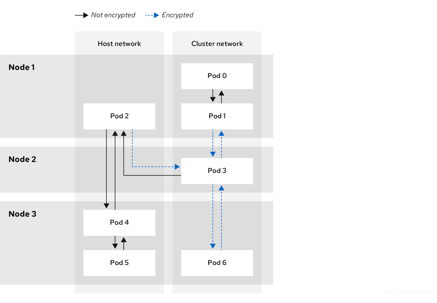
16.5.1.1. Network connectivity requirements when IPsec is enabled
You must configure the network connectivity between machines to allow OpenShift Container Platform cluster components to communicate. Each machine must be able to resolve the hostnames of all other machines in the cluster.
| Protocol | Port | Description |
|---|---|---|
| UDP |
| IPsec IKE packets |
|
| IPsec NAT-T packets | |
| ESP | N/A | IPsec Encapsulating Security Payload (ESP) |
16.5.2. Encryption protocol and tunnel mode for IPsec
The encrypt cipher used is AES-GCM-16-256. The integrity check value (ICV) is 16 bytes. The key length is 256 bits.
The IPsec tunnel mode used is Transport mode, a mode that encrypts end-to-end communication.
16.5.3. Security certificate generation and rotation
The Cluster Network Operator (CNO) generates a self-signed X.509 certificate authority (CA) that is used by IPsec for encryption. Certificate signing requests (CSRs) from each node are automatically fulfilled by the CNO.
The CA is valid for 10 years. The individual node certificates are valid for 5 years and are automatically rotated after 4 1/2 years elapse.
16.6. Configuring an egress firewall for a project
As a cluster administrator, you can create an egress firewall for a project that restricts egress traffic leaving your OpenShift Container Platform cluster.
16.6.1. How an egress firewall works in a project
As a cluster administrator, you can use an egress firewall to limit the external hosts that some or all pods can access from within the cluster. An egress firewall supports the following scenarios:
- A pod can only connect to internal hosts and cannot initiate connections to the public internet.
- A pod can only connect to the public internet and cannot initiate connections to internal hosts that are outside the OpenShift Container Platform cluster.
- A pod cannot reach specified internal subnets or hosts outside the OpenShift Container Platform cluster.
- A pod can connect to only specific external hosts.
For example, you can allow one project access to a specified IP range but deny the same access to a different project. Or you can restrict application developers from updating from Python pip mirrors, and force updates to come only from approved sources.
You configure an egress firewall policy by creating an EgressFirewall custom resource (CR) object. The egress firewall matches network traffic that meets any of the following criteria:
- An IP address range in CIDR format
- A DNS name that resolves to an IP address
- A port number
- A protocol that is one of the following protocols: TCP, UDP, and SCTP
If your egress firewall includes a deny rule for 0.0.0.0/0, access to your OpenShift Container Platform API servers is blocked. To ensure that pods can continue to access the OpenShift Container Platform API servers, you must include the IP address range that the API servers listen on in your egress firewall rules, as in the following example:
apiVersion: k8s.ovn.org/v1
kind: EgressFirewall
metadata:
name: default
namespace: <namespace>
spec:
egress:
- to:
cidrSelector: <api_server_address_range>
type: Allow
# ...
- to:
cidrSelector: 0.0.0.0/0
type: Deny
To find the IP address for your API servers, run oc get ep kubernetes -n default.
For more information, see BZ#1988324.
Egress firewall rules do not apply to traffic that goes through routers. Any user with permission to create a Route CR object can bypass egress firewall policy rules by creating a route that points to a forbidden destination.
16.6.1.1. Limitations of an egress firewall
An egress firewall has the following limitations:
- No project can have more than one EgressFirewall object.
- A maximum of one EgressFirewall object with a maximum of 8,000 rules can be defined per project.
- If you are using the OVN-Kubernetes network plugin with shared gateway mode in Red Hat OpenShift Networking, return ingress replies are affected by egress firewall rules. If the egress firewall rules drop the ingress reply destination IP, the traffic is dropped.
Violating any of these restrictions results in a broken egress firewall for the project, and might cause all external network traffic to be dropped.
An Egress Firewall resource can be created in the kube-node-lease, kube-public, kube-system, openshift and openshift- projects.
16.6.1.2. Matching order for egress firewall policy rules
The egress firewall policy rules are evaluated in the order that they are defined, from first to last. The first rule that matches an egress connection from a pod applies. Any subsequent rules are ignored for that connection.
16.6.1.3. How Domain Name Server (DNS) resolution works
If you use DNS names in any of your egress firewall policy rules, proper resolution of the domain names is subject to the following restrictions:
- Domain name updates are polled based on a time-to-live (TTL) duration. By default, the duration is 30 minutes. When the egress firewall controller queries the local name servers for a domain name, if the response includes a TTL and the TTL is less than 30 minutes, the controller sets the duration for that DNS name to the returned value. Each DNS name is queried after the TTL for the DNS record expires.
- The pod must resolve the domain from the same local name servers when necessary. Otherwise the IP addresses for the domain known by the egress firewall controller and the pod can be different. If the IP addresses for a hostname differ, the egress firewall might not be enforced consistently.
- Because the egress firewall controller and pods asynchronously poll the same local name server, the pod might obtain the updated IP address before the egress controller does, which causes a race condition. Due to this current limitation, domain name usage in EgressFirewall objects is only recommended for domains with infrequent IP address changes.
The egress firewall always allows pods access to the external interface of the node that the pod is on for DNS resolution.
If you use domain names in your egress firewall policy and your DNS resolution is not handled by a DNS server on the local node, then you must add egress firewall rules that allow access to your DNS server’s IP addresses. if you are using domain names in your pods.
16.6.2. EgressFirewall custom resource (CR) object
You can define one or more rules for an egress firewall. A rule is either an Allow rule or a Deny rule, with a specification for the traffic that the rule applies to.
The following YAML describes an EgressFirewall CR object:
EgressFirewall object
apiVersion: k8s.ovn.org/v1
kind: EgressFirewall
metadata:
name: <name>
spec:
egress:
...16.6.2.1. EgressFirewall rules
The following YAML describes an egress firewall rule object. The egress stanza expects an array of one or more objects.
Egress policy rule stanza
egress:
- type: <type>
to:
cidrSelector: <cidr>
dnsName: <dns_name>
ports:
...- 1
- The type of rule. The value must be either
AlloworDeny. - 2
- A stanza describing an egress traffic match rule that specifies the
cidrSelectorfield or thednsNamefield. You cannot use both fields in the same rule. - 3
- An IP address range in CIDR format.
- 4
- A DNS domain name.
- 5
- Optional: A stanza describing a collection of network ports and protocols for the rule.
Ports stanza
ports:
- port: <port>
protocol: <protocol> 16.6.2.2. Example EgressFirewall CR objects
The following example defines several egress firewall policy rules:
apiVersion: k8s.ovn.org/v1
kind: EgressFirewall
metadata:
name: default
spec:
egress:
- type: Allow
to:
cidrSelector: 1.2.3.0/24
- type: Deny
to:
cidrSelector: 0.0.0.0/0- 1
- A collection of egress firewall policy rule objects.
The following example defines a policy rule that denies traffic to the host at the 172.16.1.1 IP address, if the traffic is using either the TCP protocol and destination port 80 or any protocol and destination port 443.
apiVersion: k8s.ovn.org/v1
kind: EgressFirewall
metadata:
name: default
spec:
egress:
- type: Deny
to:
cidrSelector: 172.16.1.1
ports:
- port: 80
protocol: TCP
- port: 44316.6.3. Creating an egress firewall policy object
As a cluster administrator, you can create an egress firewall policy object for a project.
If the project already has an EgressFirewall object defined, you must edit the existing policy to make changes to the egress firewall rules.
Prerequisites
- A cluster that uses the OVN-Kubernetes default Container Network Interface (CNI) network provider plugin.
-
Install the OpenShift CLI (
oc). - You must log in to the cluster as a cluster administrator.
Procedure
Create a policy rule:
-
Create a
<policy_name>.yamlfile where<policy_name>describes the egress policy rules. - In the file you created, define an egress policy object.
-
Create a
Enter the following command to create the policy object. Replace
<policy_name>with the name of the policy and<project>with the project that the rule applies to.$ oc create -f <policy_name>.yaml -n <project>In the following example, a new EgressFirewall object is created in a project named
project1:$ oc create -f default.yaml -n project1Example output
egressfirewall.k8s.ovn.org/v1 created-
Optional: Save the
<policy_name>.yamlfile so that you can make changes later.
16.7. Viewing an egress firewall for a project
As a cluster administrator, you can list the names of any existing egress firewalls and view the traffic rules for a specific egress firewall.
16.7.1. Viewing an EgressFirewall object
You can view an EgressFirewall object in your cluster.
Prerequisites
- A cluster using the OVN-Kubernetes default Container Network Interface (CNI) network provider plugin.
-
Install the OpenShift Command-line Interface (CLI), commonly known as
oc. - You must log in to the cluster.
Procedure
Optional: To view the names of the EgressFirewall objects defined in your cluster, enter the following command:
$ oc get egressfirewall --all-namespacesTo inspect a policy, enter the following command. Replace
<policy_name>with the name of the policy to inspect.$ oc describe egressfirewall <policy_name>Example output
Name: default Namespace: project1 Created: 20 minutes ago Labels: <none> Annotations: <none> Rule: Allow to 1.2.3.0/24 Rule: Allow to www.example.com Rule: Deny to 0.0.0.0/0
16.8. Editing an egress firewall for a project
As a cluster administrator, you can modify network traffic rules for an existing egress firewall.
16.8.1. Editing an EgressFirewall object
As a cluster administrator, you can update the egress firewall for a project.
Prerequisites
- A cluster using the OVN-Kubernetes default Container Network Interface (CNI) network provider plugin.
-
Install the OpenShift CLI (
oc). - You must log in to the cluster as a cluster administrator.
Procedure
Find the name of the EgressFirewall object for the project. Replace
<project>with the name of the project.$ oc get -n <project> egressfirewallOptional: If you did not save a copy of the EgressFirewall object when you created the egress network firewall, enter the following command to create a copy.
$ oc get -n <project> egressfirewall <name> -o yaml > <filename>.yamlReplace
<project>with the name of the project. Replace<name>with the name of the object. Replace<filename>with the name of the file to save the YAML to.After making changes to the policy rules, enter the following command to replace the EgressFirewall object. Replace
<filename>with the name of the file containing the updated EgressFirewall object.$ oc replace -f <filename>.yaml
16.9. Removing an egress firewall from a project
As a cluster administrator, you can remove an egress firewall from a project to remove all restrictions on network traffic from the project that leaves the OpenShift Container Platform cluster.
16.9.1. Removing an EgressFirewall object
As a cluster administrator, you can remove an egress firewall from a project.
Prerequisites
- A cluster using the OVN-Kubernetes default Container Network Interface (CNI) network provider plugin.
-
Install the OpenShift CLI (
oc). - You must log in to the cluster as a cluster administrator.
Procedure
Find the name of the EgressFirewall object for the project. Replace
<project>with the name of the project.$ oc get -n <project> egressfirewallEnter the following command to delete the EgressFirewall object. Replace
<project>with the name of the project and<name>with the name of the object.$ oc delete -n <project> egressfirewall <name>
16.10. Configuring an egress IP address
As a cluster administrator, you can configure the OVN-Kubernetes default Container Network Interface (CNI) network provider to assign one or more egress IP addresses to a namespace, or to specific pods in a namespace.
16.10.1. Egress IP address architectural design and implementation
The OpenShift Container Platform egress IP address functionality allows you to ensure that the traffic from one or more pods in one or more namespaces has a consistent source IP address for services outside the cluster network.
For example, you might have a pod that periodically queries a database that is hosted on a server outside of your cluster. To enforce access requirements for the server, a packet filtering device is configured to allow traffic only from specific IP addresses. To ensure that you can reliably allow access to the server from only that specific pod, you can configure a specific egress IP address for the pod that makes the requests to the server.
An egress IP address is implemented as an additional IP address on the primary network interface of a node and must be in the same subnet as the primary IP address of the node. The additional IP address must not be assigned to any other node in the cluster.
In some cluster configurations, application pods and ingress router pods run on the same node. If you configure an egress IP address for an application project in this scenario, the IP address is not used when you send a request to a route from the application project.
16.10.1.1. Platform support
Support for the egress IP address functionality on various platforms is summarized in the following table:
The egress IP address implementation is not compatible with Amazon Web Services (AWS), Azure Cloud, or any other public cloud platform incompatible with the automatic layer 2 network manipulation required by the egress IP feature.
| Platform | Supported |
|---|---|
| Bare metal | Yes |
| vSphere | Yes |
| Red Hat OpenStack Platform (RHOSP) | No |
| Public cloud | No |
16.10.1.2. Assignment of egress IPs to pods
To assign one or more egress IPs to a namespace or specific pods in a namespace, the following conditions must be satisfied:
-
At least one node in your cluster must have the
k8s.ovn.org/egress-assignable: ""label. -
An
EgressIPobject exists that defines one or more egress IP addresses to use as the source IP address for traffic leaving the cluster from pods in a namespace.
If you create EgressIP objects prior to labeling any nodes in your cluster for egress IP assignment, OpenShift Container Platform might assign every egress IP address to the first node with the k8s.ovn.org/egress-assignable: "" label.
To ensure that egress IP addresses are widely distributed across nodes in the cluster, always apply the label to the nodes you intent to host the egress IP addresses before creating any EgressIP objects.
16.10.1.3. Assignment of egress IPs to nodes
When creating an EgressIP object, the following conditions apply to nodes that are labeled with the k8s.ovn.org/egress-assignable: "" label:
- An egress IP address is never assigned to more than one node at a time.
- An egress IP address is equally balanced between available nodes that can host the egress IP address.
-
If the
spec.EgressIPsarray in anEgressIPobject specifies more than one IP address, no node will ever host more than one of the specified addresses. - If a node becomes unavailable, any egress IP addresses assigned to it are automatically reassigned, subject to the previously described conditions.
When a pod matches the selector for multiple EgressIP objects, there is no guarantee which of the egress IP addresses that are specified in the EgressIP objects is assigned as the egress IP address for the pod.
Additionally, if an EgressIP object specifies multiple egress IP addresses, there is no guarantee which of the egress IP addresses might be used. For example, if a pod matches a selector for an EgressIP object with two egress IP addresses, 10.10.20.1 and 10.10.20.2, either might be used for each TCP connection or UDP conversation.
16.10.1.4. Architectural diagram of an egress IP address configuration
The following diagram depicts an egress IP address configuration. The diagram describes four pods in two different namespaces running on three nodes in a cluster. The nodes are assigned IP addresses from the 192.168.126.0/18 CIDR block on the host network.
Both Node 1 and Node 3 are labeled with k8s.ovn.org/egress-assignable: "" and thus available for the assignment of egress IP addresses.
The dashed lines in the diagram depict the traffic flow from pod1, pod2, and pod3 traveling through the pod network to egress the cluster from Node 1 and Node 3. When an external service receives traffic from any of the pods selected by the example EgressIP object, the source IP address is either 192.168.126.10 or 192.168.126.102.
The following resources from the diagram are illustrated in detail:
NamespaceobjectsThe namespaces are defined in the following manifest:
Namespace objects
apiVersion: v1 kind: Namespace metadata: name: namespace1 labels: env: prod --- apiVersion: v1 kind: Namespace metadata: name: namespace2 labels: env: prodEgressIPobjectThe following
EgressIPobject describes a configuration that selects all pods in any namespace with theenvlabel set toprod. The egress IP addresses for the selected pods are192.168.126.10and192.168.126.102.EgressIPobjectapiVersion: k8s.ovn.org/v1 kind: EgressIP metadata: name: egressips-prod spec: egressIPs: - 192.168.126.10 - 192.168.126.102 namespaceSelector: matchLabels: env: prod status: assignments: - node: node1 egressIP: 192.168.126.10 - node: node3 egressIP: 192.168.126.102For the configuration in the previous example, OpenShift Container Platform assigns both egress IP addresses to the available nodes. The
statusfield reflects whether and where the egress IP addresses are assigned.
16.10.2. EgressIP object
The following YAML describes the API for the EgressIP object. The scope of the object is cluster-wide; it is not created in a namespace.
apiVersion: k8s.ovn.org/v1
kind: EgressIP
metadata:
name: <name>
spec:
egressIPs:
- <ip_address>
namespaceSelector:
...
podSelector:
...- 1
- The name for the
EgressIPsobject. - 2
- An array of one or more IP addresses.
- 3
- One or more selectors for the namespaces to associate the egress IP addresses with.
- 4
- Optional: One or more selectors for pods in the specified namespaces to associate egress IP addresses with. Applying these selectors allows for the selection of a subset of pods within a namespace.
The following YAML describes the stanza for the namespace selector:
Namespace selector stanza
namespaceSelector:
matchLabels:
<label_name>: <label_value>- 1
- One or more matching rules for namespaces. If more than one match rule is provided, all matching namespaces are selected.
The following YAML describes the optional stanza for the pod selector:
Pod selector stanza
podSelector:
matchLabels:
<label_name>: <label_value>- 1
- Optional: One or more matching rules for pods in the namespaces that match the specified
namespaceSelectorrules. If specified, only pods that match are selected. Others pods in the namespace are not selected.
In the following example, the EgressIP object associates the 192.168.126.11 and 192.168.126.102 egress IP addresses with pods that have the app label set to web and are in the namespaces that have the env label set to prod:
Example EgressIP object
apiVersion: k8s.ovn.org/v1
kind: EgressIP
metadata:
name: egress-group1
spec:
egressIPs:
- 192.168.126.11
- 192.168.126.102
podSelector:
matchLabels:
app: web
namespaceSelector:
matchLabels:
env: prod
In the following example, the EgressIP object associates the 192.168.127.30 and 192.168.127.40 egress IP addresses with any pods that do not have the environment label set to development:
Example EgressIP object
apiVersion: k8s.ovn.org/v1
kind: EgressIP
metadata:
name: egress-group2
spec:
egressIPs:
- 192.168.127.30
- 192.168.127.40
namespaceSelector:
matchExpressions:
- key: environment
operator: NotIn
values:
- development16.10.3. Labeling a node to host egress IP addresses
You can apply the k8s.ovn.org/egress-assignable="" label to a node in your cluster so that OpenShift Container Platform can assign one or more egress IP addresses to the node.
Prerequisites
-
Install the OpenShift CLI (
oc). - Log in to the cluster as a cluster administrator.
Procedure
To label a node so that it can host one or more egress IP addresses, enter the following command:
$ oc label nodes <node_name> k8s.ovn.org/egress-assignable=""1 - 1
- The name of the node to label.
TipYou can alternatively apply the following YAML to add the label to a node:
apiVersion: v1 kind: Node metadata: labels: k8s.ovn.org/egress-assignable: "" name: <node_name>
16.10.4. Next steps
16.11. Assigning an egress IP address
As a cluster administrator, you can assign an egress IP address for traffic leaving the cluster from a namespace or from specific pods in a namespace.
16.11.1. Assigning an egress IP address to a namespace
You can assign one or more egress IP addresses to a namespace or to specific pods in a namespace.
Prerequisites
-
Install the OpenShift CLI (
oc). - Log in to the cluster as a cluster administrator.
- Configure at least one node to host an egress IP address.
Procedure
Create an
EgressIPobject:-
Create a
<egressips_name>.yamlfile where<egressips_name>is the name of the object. In the file that you created, define an
EgressIPobject, as in the following example:apiVersion: k8s.ovn.org/v1 kind: EgressIP metadata: name: egress-project1 spec: egressIPs: - 192.168.127.10 - 192.168.127.11 namespaceSelector: matchLabels: env: qa
-
Create a
To create the object, enter the following command.
$ oc apply -f <egressips_name>.yaml1 - 1
- Replace
<egressips_name>with the name of the object.
Example output
egressips.k8s.ovn.org/<egressips_name> created-
Optional: Save the
<egressips_name>.yamlfile so that you can make changes later. Add labels to the namespace that requires egress IP addresses. To add a label to the namespace of an
EgressIPobject defined in step 1, run the following command:$ oc label ns <namespace> env=qa1 - 1
- Replace
<namespace>with the namespace that requires egress IP addresses.
16.12. Considerations for the use of an egress router pod
16.12.1. About an egress router pod
The OpenShift Container Platform egress router pod redirects traffic to a specified remote server from a private source IP address that is not used for any other purpose. An egress router pod can send network traffic to servers that are set up to allow access only from specific IP addresses.
The egress router pod is not intended for every outgoing connection. Creating large numbers of egress router pods can exceed the limits of your network hardware. For example, creating an egress router pod for every project or application could exceed the number of local MAC addresses that the network interface can handle before reverting to filtering MAC addresses in software.
The egress router image is not compatible with Amazon AWS, Azure Cloud, or any other cloud platform that does not support layer 2 manipulations due to their incompatibility with macvlan traffic.
16.12.1.1. Egress router modes
In redirect mode, an egress router pod configures iptables rules to redirect traffic from its own IP address to one or more destination IP addresses. Client pods that need to use the reserved source IP address must be modified to connect to the egress router rather than connecting directly to the destination IP.
The egress router CNI plugin supports redirect mode only. This is a difference with the egress router implementation that you can deploy with OpenShift SDN. Unlike the egress router for OpenShift SDN, the egress router CNI plugin does not support HTTP proxy mode or DNS proxy mode.
16.12.1.2. Egress router pod implementation
The egress router implementation uses the egress router Container Network Interface (CNI) plugin. The plugin adds a secondary network interface to a pod.
An egress router is a pod that has two network interfaces. For example, the pod can have eth0 and net1 network interfaces. The eth0 interface is on the cluster network and the pod continues to use the interface for ordinary cluster-related network traffic. The net1 interface is on a secondary network and has an IP address and gateway for that network. Other pods in the OpenShift Container Platform cluster can access the egress router service and the service enables the pods to access external services. The egress router acts as a bridge between pods and an external system.
Traffic that leaves the egress router exits through a node, but the packets have the MAC address of the net1 interface from the egress router pod.
When you add an egress router custom resource, the Cluster Network Operator creates the following objects:
-
The network attachment definition for the
net1secondary network interface of the pod. - A deployment for the egress router.
If you delete an egress router custom resource, the Operator deletes the two objects in the preceding list that are associated with the egress router.
16.12.1.3. Deployment considerations
An egress router pod adds an additional IP address and MAC address to the primary network interface of the node. As a result, you might need to configure your hypervisor or cloud provider to allow the additional address.
- Red Hat OpenStack Platform (RHOSP)
If you deploy OpenShift Container Platform on RHOSP, you must allow traffic from the IP and MAC addresses of the egress router pod on your OpenStack environment. If you do not allow the traffic, then communication will fail:
$ openstack port set --allowed-address \ ip_address=<ip_address>,mac_address=<mac_address> <neutron_port_uuid>- Red Hat Virtualization (RHV)
- If you are using RHV, you must select No Network Filter for the Virtual network interface controller (vNIC).
- VMware vSphere
- If you are using VMware vSphere, see the VMware documentation for securing vSphere standard switches. View and change VMware vSphere default settings by selecting the host virtual switch from the vSphere Web Client.
Specifically, ensure that the following are enabled:
16.12.1.4. Failover configuration
To avoid downtime, the Cluster Network Operator deploys the egress router pod as a deployment resource. The deployment name is egress-router-cni-deployment. The pod that corresponds to the deployment has a label of app=egress-router-cni.
To create a new service for the deployment, use the oc expose deployment/egress-router-cni-deployment --port <port_number> command or create a file like the following example:
apiVersion: v1
kind: Service
metadata:
name: app-egress
spec:
ports:
- name: tcp-8080
protocol: TCP
port: 8080
- name: tcp-8443
protocol: TCP
port: 8443
- name: udp-80
protocol: UDP
port: 80
type: ClusterIP
selector:
app: egress-router-cni16.13. Deploying an egress router pod in redirect mode
As a cluster administrator, you can deploy an egress router pod to redirect traffic to specified destination IP addresses from a reserved source IP address.
The egress router implementation uses the egress router Container Network Interface (CNI) plugin.
16.13.1. Egress router custom resource
Define the configuration for an egress router pod in an egress router custom resource. The following YAML describes the fields for the configuration of an egress router in redirect mode:
apiVersion: network.operator.openshift.io/v1
kind: EgressRouter
metadata:
name: <egress_router_name>
namespace: <namespace> <.>
spec:
addresses: [ <.>
{
ip: "<egress_router>", <.>
gateway: "<egress_gateway>" <.>
}
]
mode: Redirect
redirect: {
redirectRules: [ <.>
{
destinationIP: "<egress_destination>",
port: <egress_router_port>,
targetPort: <target_port>, <.>
protocol: <network_protocol> <.>
},
...
],
fallbackIP: "<egress_destination>" <.>
}
<.> Optional: The namespace field specifies the namespace to create the egress router in. If you do not specify a value in the file or on the command line, the default namespace is used.
<.> The addresses field specifies the IP addresses to configure on the secondary network interface.
<.> The ip field specifies the reserved source IP address and netmask from the physical network that the node is on to use with egress router pod. Use CIDR notation to specify the IP address and netmask.
<.> The gateway field specifies the IP address of the network gateway.
<.> Optional: The redirectRules field specifies a combination of egress destination IP address, egress router port, and protocol. Incoming connections to the egress router on the specified port and protocol are routed to the destination IP address.
<.> Optional: The targetPort field specifies the network port on the destination IP address. If this field is not specified, traffic is routed to the same network port that it arrived on.
<.> The protocol field supports TCP, UDP, or SCTP.
<.> Optional: The fallbackIP field specifies a destination IP address. If you do not specify any redirect rules, the egress router sends all traffic to this fallback IP address. If you specify redirect rules, any connections to network ports that are not defined in the rules are sent by the egress router to this fallback IP address. If you do not specify this field, the egress router rejects connections to network ports that are not defined in the rules.
Example egress router specification
apiVersion: network.operator.openshift.io/v1
kind: EgressRouter
metadata:
name: egress-router-redirect
spec:
networkInterface: {
macvlan: {
mode: "Bridge"
}
}
addresses: [
{
ip: "192.168.12.99/24",
gateway: "192.168.12.1"
}
]
mode: Redirect
redirect: {
redirectRules: [
{
destinationIP: "10.0.0.99",
port: 80,
protocol: UDP
},
{
destinationIP: "203.0.113.26",
port: 8080,
targetPort: 80,
protocol: TCP
},
{
destinationIP: "203.0.113.27",
port: 8443,
targetPort: 443,
protocol: TCP
}
]
}16.13.2. Deploying an egress router in redirect mode
You can deploy an egress router to redirect traffic from its own reserved source IP address to one or more destination IP addresses.
After you add an egress router, the client pods that need to use the reserved source IP address must be modified to connect to the egress router rather than connecting directly to the destination IP.
Prerequisites
-
Install the OpenShift CLI (
oc). -
Log in as a user with
cluster-adminprivileges.
Procedure
- Create an egress router definition.
To ensure that other pods can find the IP address of the egress router pod, create a service that uses the egress router, as in the following example:
apiVersion: v1 kind: Service metadata: name: egress-1 spec: ports: - name: web-app protocol: TCP port: 8080 type: ClusterIP selector: app: egress-router-cni <.><.> Specify the label for the egress router. The value shown is added by the Cluster Network Operator and is not configurable.
After you create the service, your pods can connect to the service. The egress router pod redirects traffic to the corresponding port on the destination IP address. The connections originate from the reserved source IP address.
Verification
To verify that the Cluster Network Operator started the egress router, complete the following procedure:
View the network attachment definition that the Operator created for the egress router:
$ oc get network-attachment-definition egress-router-cni-nadThe name of the network attachment definition is not configurable.
Example output
NAME AGE egress-router-cni-nad 18mView the deployment for the egress router pod:
$ oc get deployment egress-router-cni-deploymentThe name of the deployment is not configurable.
Example output
NAME READY UP-TO-DATE AVAILABLE AGE egress-router-cni-deployment 1/1 1 1 18mView the status of the egress router pod:
$ oc get pods -l app=egress-router-cniExample output
NAME READY STATUS RESTARTS AGE egress-router-cni-deployment-575465c75c-qkq6m 1/1 Running 0 18m- View the logs and the routing table for the egress router pod.
Get the node name for the egress router pod:
$ POD_NODENAME=$(oc get pod -l app=egress-router-cni -o jsonpath="{.items[0].spec.nodeName}")Enter into a debug session on the target node. This step instantiates a debug pod called
<node_name>-debug:$ oc debug node/$POD_NODENAMESet
/hostas the root directory within the debug shell. The debug pod mounts the root file system of the host in/hostwithin the pod. By changing the root directory to/host, you can run binaries from the executable paths of the host:# chroot /hostFrom within the
chrootenvironment console, display the egress router logs:# cat /tmp/egress-router-logExample output
2021-04-26T12:27:20Z [debug] Called CNI ADD 2021-04-26T12:27:20Z [debug] Gateway: 192.168.12.1 2021-04-26T12:27:20Z [debug] IP Source Addresses: [192.168.12.99/24] 2021-04-26T12:27:20Z [debug] IP Destinations: [80 UDP 10.0.0.99/30 8080 TCP 203.0.113.26/30 80 8443 TCP 203.0.113.27/30 443] 2021-04-26T12:27:20Z [debug] Created macvlan interface 2021-04-26T12:27:20Z [debug] Renamed macvlan to "net1" 2021-04-26T12:27:20Z [debug] Adding route to gateway 192.168.12.1 on macvlan interface 2021-04-26T12:27:20Z [debug] deleted default route {Ifindex: 3 Dst: <nil> Src: <nil> Gw: 10.128.10.1 Flags: [] Table: 254} 2021-04-26T12:27:20Z [debug] Added new default route with gateway 192.168.12.1 2021-04-26T12:27:20Z [debug] Added iptables rule: iptables -t nat PREROUTING -i eth0 -p UDP --dport 80 -j DNAT --to-destination 10.0.0.99 2021-04-26T12:27:20Z [debug] Added iptables rule: iptables -t nat PREROUTING -i eth0 -p TCP --dport 8080 -j DNAT --to-destination 203.0.113.26:80 2021-04-26T12:27:20Z [debug] Added iptables rule: iptables -t nat PREROUTING -i eth0 -p TCP --dport 8443 -j DNAT --to-destination 203.0.113.27:443 2021-04-26T12:27:20Z [debug] Added iptables rule: iptables -t nat -o net1 -j SNAT --to-source 192.168.12.99The logging file location and logging level are not configurable when you start the egress router by creating an
EgressRouterobject as described in this procedure.From within the
chrootenvironment console, get the container ID:# crictl ps --name egress-router-cni-pod | awk '{print $1}'Example output
CONTAINER bac9fae69ddb6Determine the process ID of the container. In this example, the container ID is
bac9fae69ddb6:# crictl inspect -o yaml bac9fae69ddb6 | grep 'pid:' | awk '{print $2}'Example output
68857Enter the network namespace of the container:
# nsenter -n -t 68857Display the routing table:
# ip routeIn the following example output, the
net1network interface is the default route. Traffic for the cluster network uses theeth0network interface. Traffic for the192.168.12.0/24network uses thenet1network interface and originates from the reserved source IP address192.168.12.99. The pod routes all other traffic to the gateway at IP address192.168.12.1. Routing for the service network is not shown.Example output
default via 192.168.12.1 dev net1 10.128.10.0/23 dev eth0 proto kernel scope link src 10.128.10.18 192.168.12.0/24 dev net1 proto kernel scope link src 192.168.12.99 192.168.12.1 dev net1
16.14. Enabling multicast for a project
16.14.1. About multicast
With IP multicast, data is broadcast to many IP addresses simultaneously.
At this time, multicast is best used for low-bandwidth coordination or service discovery and not a high-bandwidth solution.
Multicast traffic between OpenShift Container Platform pods is disabled by default. If you are using the OVN-Kubernetes default Container Network Interface (CNI) network provider, you can enable multicast on a per-project basis.
16.14.2. Enabling multicast between pods
You can enable multicast between pods for your project.
Prerequisites
-
Install the OpenShift CLI (
oc). -
You must log in to the cluster with a user that has the
cluster-adminrole.
Procedure
Run the following command to enable multicast for a project. Replace
<namespace>with the namespace for the project you want to enable multicast for.$ oc annotate namespace <namespace> \ k8s.ovn.org/multicast-enabled=trueTipYou can alternatively apply the following YAML to add the annotation:
apiVersion: v1 kind: Namespace metadata: name: <namespace> annotations: k8s.ovn.org/multicast-enabled: "true"
Verification
To verify that multicast is enabled for a project, complete the following procedure:
Change your current project to the project that you enabled multicast for. Replace
<project>with the project name.$ oc project <project>Create a pod to act as a multicast receiver:
$ cat <<EOF| oc create -f - apiVersion: v1 kind: Pod metadata: name: mlistener labels: app: multicast-verify spec: containers: - name: mlistener image: registry.access.redhat.com/ubi8 command: ["/bin/sh", "-c"] args: ["dnf -y install socat hostname && sleep inf"] ports: - containerPort: 30102 name: mlistener protocol: UDP EOFCreate a pod to act as a multicast sender:
$ cat <<EOF| oc create -f - apiVersion: v1 kind: Pod metadata: name: msender labels: app: multicast-verify spec: containers: - name: msender image: registry.access.redhat.com/ubi8 command: ["/bin/sh", "-c"] args: ["dnf -y install socat && sleep inf"] EOFIn a new terminal window or tab, start the multicast listener.
Get the IP address for the Pod:
$ POD_IP=$(oc get pods mlistener -o jsonpath='{.status.podIP}')Start the multicast listener by entering the following command:
$ oc exec mlistener -i -t -- \ socat UDP4-RECVFROM:30102,ip-add-membership=224.1.0.1:$POD_IP,fork EXEC:hostname
Start the multicast transmitter.
Get the pod network IP address range:
$ CIDR=$(oc get Network.config.openshift.io cluster \ -o jsonpath='{.status.clusterNetwork[0].cidr}')To send a multicast message, enter the following command:
$ oc exec msender -i -t -- \ /bin/bash -c "echo | socat STDIO UDP4-DATAGRAM:224.1.0.1:30102,range=$CIDR,ip-multicast-ttl=64"If multicast is working, the previous command returns the following output:
mlistener
16.15. Disabling multicast for a project
16.15.1. Disabling multicast between pods
You can disable multicast between pods for your project.
Prerequisites
-
Install the OpenShift CLI (
oc). -
You must log in to the cluster with a user that has the
cluster-adminrole.
Procedure
Disable multicast by running the following command:
$ oc annotate namespace <namespace> \1 k8s.ovn.org/multicast-enabled-- 1
- The
namespacefor the project you want to disable multicast for.
TipYou can alternatively apply the following YAML to delete the annotation:
apiVersion: v1 kind: Namespace metadata: name: <namespace> annotations: k8s.ovn.org/multicast-enabled: null
16.16. Tracking network flows
As a cluster administrator, you can collect information about pod network flows from your cluster to assist with the following areas:
- Monitor ingress and egress traffic on the pod network.
- Troubleshoot performance issues.
- Gather data for capacity planning and security audits.
When you enable the collection of the network flows, only the metadata about the traffic is collected. For example, packet data is not collected, but the protocol, source address, destination address, port numbers, number of bytes, and other packet-level information is collected.
The data is collected in one or more of the following record formats:
- NetFlow
- sFlow
- IPFIX
When you configure the Cluster Network Operator (CNO) with one or more collector IP addresses and port numbers, the Operator configures Open vSwitch (OVS) on each node to send the network flows records to each collector.
You can configure the Operator to send records to more than one type of network flow collector. For example, you can send records to NetFlow collectors and also send records to sFlow collectors.
When OVS sends data to the collectors, each type of collector receives identical records. For example, if you configure two NetFlow collectors, OVS on a node sends identical records to the two collectors. If you also configure two sFlow collectors, the two sFlow collectors receive identical records. However, each collector type has a unique record format.
Collecting the network flows data and sending the records to collectors affects performance. Nodes process packets at a slower rate. If the performance impact is too great, you can delete the destinations for collectors to disable collecting network flows data and restore performance.
Enabling network flow collectors might have an impact on the overall performance of the cluster network.
16.16.1. Network object configuration for tracking network flows
The fields for configuring network flows collectors in the Cluster Network Operator (CNO) are shown in the following table:
| Field | Type | Description |
|---|---|---|
|
|
|
The name of the CNO object. This name is always |
|
|
|
One or more of |
|
|
| A list of IP address and network port pairs for up to 10 collectors. |
|
|
| A list of IP address and network port pairs for up to 10 collectors. |
|
|
| A list of IP address and network port pairs for up to 10 collectors. |
After applying the following manifest to the CNO, the Operator configures Open vSwitch (OVS) on each node in the cluster to send network flows records to the NetFlow collector that is listening at 192.168.1.99:2056.
Example configuration for tracking network flows
apiVersion: operator.openshift.io/v1
kind: Network
metadata:
name: cluster
spec:
exportNetworkFlows:
netFlow:
collectors:
- 192.168.1.99:205616.16.2. Adding destinations for network flows collectors
As a cluster administrator, you can configure the Cluster Network Operator (CNO) to send network flows metadata about the pod network to a network flows collector.
Prerequisites
-
You installed the OpenShift CLI (
oc). -
You are logged in to the cluster with a user with
cluster-adminprivileges. - You have a network flows collector and know the IP address and port that it listens on.
Procedure
Create a patch file that specifies the network flows collector type and the IP address and port information of the collectors:
spec: exportNetworkFlows: netFlow: collectors: - 192.168.1.99:2056Configure the CNO with the network flows collectors:
$ oc patch network.operator cluster --type merge -p "$(cat <file_name>.yaml)"Example output
network.operator.openshift.io/cluster patched
Verification
Verification is not typically necessary. You can run the following command to confirm that Open vSwitch (OVS) on each node is configured to send network flows records to one or more collectors.
View the Operator configuration to confirm that the
exportNetworkFlowsfield is configured:$ oc get network.operator cluster -o jsonpath="{.spec.exportNetworkFlows}"Example output
{"netFlow":{"collectors":["192.168.1.99:2056"]}}View the network flows configuration in OVS from each node:
$ for pod in $(oc get pods -n openshift-ovn-kubernetes -l app=ovnkube-node -o jsonpath='{range@.items[*]}{.metadata.name}{"\n"}{end}'); do ; echo; echo $pod; oc -n openshift-ovn-kubernetes exec -c ovnkube-node $pod \ -- bash -c 'for type in ipfix sflow netflow ; do ovs-vsctl find $type ; done'; doneExample output
ovnkube-node-xrn4p _uuid : a4d2aaca-5023-4f3d-9400-7275f92611f9 active_timeout : 60 add_id_to_interface : false engine_id : [] engine_type : [] external_ids : {} targets : ["192.168.1.99:2056"] ovnkube-node-z4vq9 _uuid : 61d02fdb-9228-4993-8ff5-b27f01a29bd6 active_timeout : 60 add_id_to_interface : false engine_id : [] engine_type : [] external_ids : {} targets : ["192.168.1.99:2056"]- ...
16.16.3. Deleting all destinations for network flows collectors
As a cluster administrator, you can configure the Cluster Network Operator (CNO) to stop sending network flows metadata to a network flows collector.
Prerequisites
-
You installed the OpenShift CLI (
oc). -
You are logged in to the cluster with a user with
cluster-adminprivileges.
Procedure
Remove all network flows collectors:
$ oc patch network.operator cluster --type='json' \ -p='[{"op":"remove", "path":"/spec/exportNetworkFlows"}]'Example output
network.operator.openshift.io/cluster patched
16.17. Configuring hybrid networking
As a cluster administrator, you can configure the OVN-Kubernetes Container Network Interface (CNI) cluster network provider to allow Linux and Windows nodes to host Linux and Windows workloads, respectively.
16.17.1. Configuring hybrid networking with OVN-Kubernetes
You can configure your cluster to use hybrid networking with OVN-Kubernetes. This allows a hybrid cluster that supports different node networking configurations. For example, this is necessary to run both Linux and Windows nodes in a cluster.
You must configure hybrid networking with OVN-Kubernetes during the installation of your cluster. You cannot switch to hybrid networking after the installation process.
Prerequisites
-
You defined
OVNKubernetesfor thenetworking.networkTypeparameter in theinstall-config.yamlfile. See the installation documentation for configuring OpenShift Container Platform network customizations on your chosen cloud provider for more information.
Procedure
Change to the directory that contains the installation program and create the manifests:
$ ./openshift-install create manifests --dir <installation_directory>where:
<installation_directory>-
Specifies the name of the directory that contains the
install-config.yamlfile for your cluster.
Create a stub manifest file for the advanced network configuration that is named
cluster-network-03-config.ymlin the<installation_directory>/manifests/directory:$ cat <<EOF > <installation_directory>/manifests/cluster-network-03-config.yml apiVersion: operator.openshift.io/v1 kind: Network metadata: name: cluster spec: EOFwhere:
<installation_directory>-
Specifies the directory name that contains the
manifests/directory for your cluster.
Open the
cluster-network-03-config.ymlfile in an editor and configure OVN-Kubernetes with hybrid networking, such as in the following example:Specify a hybrid networking configuration
apiVersion: operator.openshift.io/v1 kind: Network metadata: name: cluster spec: defaultNetwork: ovnKubernetesConfig: hybridOverlayConfig: hybridClusterNetwork:1 - cidr: 10.132.0.0/14 hostPrefix: 23 hybridOverlayVXLANPort: 98982 - 1
- Specify the CIDR configuration used for nodes on the additional overlay network. The
hybridClusterNetworkCIDR cannot overlap with theclusterNetworkCIDR. - 2
- Specify a custom VXLAN port for the additional overlay network. This is required for running Windows nodes in a cluster installed on vSphere, and must not be configured for any other cloud provider. The custom port can be any open port excluding the default
4789port. For more information on this requirement, see the Microsoft documentation on Pod-to-pod connectivity between hosts is broken.
NoteWindows Server Long-Term Servicing Channel (LTSC): Windows Server 2019 is not supported on clusters with a custom
hybridOverlayVXLANPortvalue because this Windows server version does not support selecting a custom VXLAN port.-
Save the
cluster-network-03-config.ymlfile and quit the text editor. -
Optional: Back up the
manifests/cluster-network-03-config.ymlfile. The installation program deletes themanifests/directory when creating the cluster.
Complete any further installation configurations, and then create your cluster. Hybrid networking is enabled when the installation process is finished.
Chapter 17. Configuring Routes
17.1. Route configuration
17.1.1. Creating an HTTP-based route
A route allows you to host your application at a public URL. It can either be secure or unsecured, depending on the network security configuration of your application. An HTTP-based route is an unsecured route that uses the basic HTTP routing protocol and exposes a service on an unsecured application port.
The following procedure describes how to create a simple HTTP-based route to a web application, using the hello-openshift application as an example.
Prerequisites
-
You installed the OpenShift CLI (
oc). - You are logged in as an administrator.
- You have a web application that exposes a port and a TCP endpoint listening for traffic on the port.
Procedure
Create a project called
hello-openshiftby running the following command:$ oc new-project hello-openshiftCreate a pod in the project by running the following command:
$ oc create -f https://raw.githubusercontent.com/openshift/origin/master/examples/hello-openshift/hello-pod.jsonCreate a service called
hello-openshiftby running the following command:$ oc expose pod/hello-openshiftCreate an unsecured route to the
hello-openshiftapplication by running the following command:$ oc expose svc hello-openshiftIf you examine the resulting
Routeresource, it should look similar to the following:YAML definition of the created unsecured route:
apiVersion: route.openshift.io/v1 kind: Route metadata: name: hello-openshift spec: host: hello-openshift-hello-openshift.<Ingress_Domain>1 port: targetPort: 80802 to: kind: Service name: hello-openshift- 1
<Ingress_Domain>is the default ingress domain name. Theingresses.config/clusterobject is created during the installation and cannot be changed. If you want to specify a different domain, you can specify an alternative cluster domain using theappsDomainoption.- 2
targetPortis the target port on pods that is selected by the service that this route points to.
NoteTo display your default ingress domain, run the following command:
$ oc get ingresses.config/cluster -o jsonpath={.spec.domain}
17.1.2. Configuring route timeouts
You can configure the default timeouts for an existing route when you have services in need of a low timeout, which is required for Service Level Availability (SLA) purposes, or a high timeout, for cases with a slow back end.
Prerequisites
- You need a deployed Ingress Controller on a running cluster.
Procedure
Using the
oc annotatecommand, add the timeout to the route:$ oc annotate route <route_name> \ --overwrite haproxy.router.openshift.io/timeout=<timeout><time_unit>1 - 1
- Supported time units are microseconds (us), milliseconds (ms), seconds (s), minutes (m), hours (h), or days (d).
The following example sets a timeout of two seconds on a route named
myroute:$ oc annotate route myroute --overwrite haproxy.router.openshift.io/timeout=2s
17.1.3. Enabling HTTP strict transport security
HTTP Strict Transport Security (HSTS) policy is a security enhancement, which ensures that only HTTPS traffic is allowed on the host. Any HTTP requests are dropped by default. This is useful for ensuring secure interactions with websites, or to offer a secure application for the user’s benefit.
When HSTS is enabled, HSTS adds a Strict Transport Security header to HTTPS responses from the site. You can use the insecureEdgeTerminationPolicy value in a route to redirect to send HTTP to HTTPS. However, when HSTS is enabled, the client changes all requests from the HTTP URL to HTTPS before the request is sent, eliminating the need for a redirect. This is not required to be supported by the client, and can be disabled by setting max-age=0.
HSTS works only with secure routes (either edge terminated or re-encrypt). The configuration is ineffective on HTTP or passthrough routes.
Procedure
To enable HSTS on a route, add the
haproxy.router.openshift.io/hsts_headervalue to the edge terminated or re-encrypt route:apiVersion: v1 kind: Route metadata: annotations: haproxy.router.openshift.io/hsts_header: max-age=31536000;includeSubDomains;preload1 2 3 - 1
max-ageis the only required parameter. It measures the length of time, in seconds, that the HSTS policy is in effect. The client updatesmax-agewhenever a response with a HSTS header is received from the host. Whenmax-agetimes out, the client discards the policy.- 2
includeSubDomainsis optional. When included, it tells the client that all subdomains of the host are to be treated the same as the host.- 3
preloadis optional. Whenmax-ageis greater than 0, then includingpreloadinhaproxy.router.openshift.io/hsts_headerallows external services to include this site in their HSTS preload lists. For example, sites such as Google can construct a list of sites that havepreloadset. Browsers can then use these lists to determine which sites they can communicate with over HTTPS, before they have interacted with the site. Withoutpreloadset, browsers must have interacted with the site over HTTPS to get the header.
17.1.4. Troubleshooting throughput issues
Sometimes applications deployed through OpenShift Container Platform can cause network throughput issues such as unusually high latency between specific services.
Use the following methods to analyze performance issues if pod logs do not reveal any cause of the problem:
Use a packet analyzer, such as ping or tcpdump to analyze traffic between a pod and its node.
For example, run the tcpdump tool on each pod while reproducing the behavior that led to the issue. Review the captures on both sides to compare send and receive timestamps to analyze the latency of traffic to and from a pod. Latency can occur in OpenShift Container Platform if a node interface is overloaded with traffic from other pods, storage devices, or the data plane.
$ tcpdump -s 0 -i any -w /tmp/dump.pcap host <podip 1> && host <podip 2>1 - 1
podipis the IP address for the pod. Run theoc get pod <pod_name> -o widecommand to get the IP address of a pod.
tcpdump generates a file at
/tmp/dump.pcapcontaining all traffic between these two pods. Ideally, run the analyzer shortly before the issue is reproduced and stop the analyzer shortly after the issue is finished reproducing to minimize the size of the file. You can also run a packet analyzer between the nodes (eliminating the SDN from the equation) with:$ tcpdump -s 0 -i any -w /tmp/dump.pcap port 4789Use a bandwidth measuring tool, such as iperf, to measure streaming throughput and UDP throughput. Run the tool from the pods first, then from the nodes, to locate any bottlenecks.
- For information on installing and using iperf, see this Red Hat Solution.
17.1.5. Using cookies to keep route statefulness
OpenShift Container Platform provides sticky sessions, which enables stateful application traffic by ensuring all traffic hits the same endpoint. However, if the endpoint pod terminates, whether through restart, scaling, or a change in configuration, this statefulness can disappear.
OpenShift Container Platform can use cookies to configure session persistence. The Ingress controller selects an endpoint to handle any user requests, and creates a cookie for the session. The cookie is passed back in the response to the request and the user sends the cookie back with the next request in the session. The cookie tells the Ingress Controller which endpoint is handling the session, ensuring that client requests use the cookie so that they are routed to the same pod.
Cookies cannot be set on passthrough routes, because the HTTP traffic cannot be seen. Instead, a number is calculated based on the source IP address, which determines the backend.
If backends change, the traffic can be directed to the wrong server, making it less sticky. If you are using a load balancer, which hides source IP, the same number is set for all connections and traffic is sent to the same pod.
17.1.5.1. Annotating a route with a cookie
You can set a cookie name to overwrite the default, auto-generated one for the route. This allows the application receiving route traffic to know the cookie name. By deleting the cookie it can force the next request to re-choose an endpoint. So, if a server was overloaded it tries to remove the requests from the client and redistribute them.
Procedure
Annotate the route with the specified cookie name:
$ oc annotate route <route_name> router.openshift.io/cookie_name="<cookie_name>"where:
<route_name>- Specifies the name of the route.
<cookie_name>- Specifies the name for the cookie.
For example, to annotate the route
my_routewith the cookie namemy_cookie:$ oc annotate route my_route router.openshift.io/cookie_name="my_cookie"Capture the route hostname in a variable:
$ ROUTE_NAME=$(oc get route <route_name> -o jsonpath='{.spec.host}')where:
<route_name>- Specifies the name of the route.
Save the cookie, and then access the route:
$ curl $ROUTE_NAME -k -c /tmp/cookie_jarUse the cookie saved by the previous command when connecting to the route:
$ curl $ROUTE_NAME -k -b /tmp/cookie_jar
17.1.6. Path-based routes
Path-based routes specify a path component that can be compared against a URL, which requires that the traffic for the route be HTTP based. Thus, multiple routes can be served using the same hostname, each with a different path. Routers should match routes based on the most specific path to the least. However, this depends on the router implementation.
The following table shows example routes and their accessibility:
| Route | When Compared to | Accessible |
|---|---|---|
| www.example.com/test | www.example.com/test | Yes |
| www.example.com | No | |
| www.example.com/test and www.example.com | www.example.com/test | Yes |
| www.example.com | Yes | |
| www.example.com | www.example.com/text | Yes (Matched by the host, not the route) |
| www.example.com | Yes |
An unsecured route with a path
apiVersion: route.openshift.io/v1
kind: Route
metadata:
name: route-unsecured
spec:
host: www.example.com
path: "/test"
to:
kind: Service
name: service-name- 1
- The path is the only added attribute for a path-based route.
Path-based routing is not available when using passthrough TLS, as the router does not terminate TLS in that case and cannot read the contents of the request.
17.1.7. Route-specific annotations
The Ingress Controller can set the default options for all the routes it exposes. An individual route can override some of these defaults by providing specific configurations in its annotations. Red Hat does not support adding a route annotation to an operator-managed route.
To create a whitelist with multiple source IPs or subnets, use a space-delimited list. Any other delimiter type causes the list to be ignored without a warning or error message.
| Variable | Description | Environment variable used as default |
|---|---|---|
|
|
Sets the load-balancing algorithm. Available options are |
|
|
|
Disables the use of cookies to track related connections. If set to | |
|
| Specifies an optional cookie to use for this route. The name must consist of any combination of upper and lower case letters, digits, "_", and "-". The default is the hashed internal key name for the route. | |
|
|
Sets the maximum number of connections that are allowed to a backing pod from a router. | |
|
|
Setting | |
|
|
Limits the number of concurrent TCP connections made through the same source IP address. It accepts a numeric value. | |
|
|
Limits the rate at which a client with the same source IP address can make HTTP requests. It accepts a numeric value. | |
|
|
Limits the rate at which a client with the same source IP address can make TCP connections. It accepts a numeric value. | |
|
| Sets a server-side timeout for the route. (TimeUnits) |
|
|
| This timeout applies to a tunnel connection, for example, WebSocket over cleartext, edge, reencrypt, or passthrough routes. With cleartext, edge, or reencrypt route types, this annotation is applied as a timeout tunnel with the existing timeout value. For the passthrough route types, the annotation takes precedence over any existing timeout value set. |
|
|
|
You can set either an IngressController or the ingress config . This annotation redeploys the router and configures the HA proxy to emit the haproxy |
|
|
| Sets the interval for the back-end health checks. (TimeUnits) |
|
|
| Sets a whitelist for the route. The whitelist is a space-separated list of IP addresses and CIDR ranges for the approved source addresses. Requests from IP addresses that are not in the whitelist are dropped. The maximum number of IP addresses and CIDR ranges allowed in a whitelist is 61. | |
|
| Sets a Strict-Transport-Security header for the edge terminated or re-encrypt route. | |
|
|
Sets the | |
|
| Sets the rewrite path of the request on the backend. | |
|
| Sets a value to restrict cookies. The values are:
This value is applicable to re-encrypt and edge routes only. For more information, see the SameSite cookies documentation. | |
|
|
Sets the policy for handling the
|
|
Environment variables cannot be edited.
Router timeout variables
TimeUnits are represented by a number followed by the unit: us *(microseconds), ms (milliseconds, default), s (seconds), m (minutes), h *(hours), d (days).
The regular expression is: [1-9][0-9]*(us\|ms\|s\|m\|h\|d).
| Variable | Default | Description |
|---|---|---|
|
|
| Length of time between subsequent liveness checks on back ends. |
|
|
| Controls the TCP FIN timeout period for the client connecting to the route. If the FIN sent to close the connection does not answer within the given time, HAProxy closes the connection. This is harmless if set to a low value and uses fewer resources on the router. |
|
|
| Length of time that a client has to acknowledge or send data. |
|
|
| The maximum connection time. |
|
|
| Controls the TCP FIN timeout from the router to the pod backing the route. |
|
|
| Length of time that a server has to acknowledge or send data. |
|
|
| Length of time for TCP or WebSocket connections to remain open. This timeout period resets whenever HAProxy reloads. |
|
|
|
Set the maximum time to wait for a new HTTP request to appear. If this is set too low, it can cause problems with browsers and applications not expecting a small
Some effective timeout values can be the sum of certain variables, rather than the specific expected timeout. For example, |
|
|
| Length of time the transmission of an HTTP request can take. |
|
|
| Allows the minimum frequency for the router to reload and accept new changes. |
|
|
| Timeout for the gathering of HAProxy metrics. |
A route setting custom timeout
apiVersion: route.openshift.io/v1
kind: Route
metadata:
annotations:
haproxy.router.openshift.io/timeout: 5500ms
...- 1
- Specifies the new timeout with HAProxy supported units (
us,ms,s,m,h,d). If the unit is not provided,msis the default.
Setting a server-side timeout value for passthrough routes too low can cause WebSocket connections to timeout frequently on that route.
A route that allows only one specific IP address
metadata:
annotations:
haproxy.router.openshift.io/ip_whitelist: 192.168.1.10A route that allows several IP addresses
metadata:
annotations:
haproxy.router.openshift.io/ip_whitelist: 192.168.1.10 192.168.1.11 192.168.1.12A route that allows an IP address CIDR network
metadata:
annotations:
haproxy.router.openshift.io/ip_whitelist: 192.168.1.0/24A route that allows both IP an address and IP address CIDR networks
metadata:
annotations:
haproxy.router.openshift.io/ip_whitelist: 180.5.61.153 192.168.1.0/24 10.0.0.0/8A route specifying a rewrite target
apiVersion: route.openshift.io/v1
kind: Route
metadata:
annotations:
haproxy.router.openshift.io/rewrite-target: /
...- 1
- Sets
/as rewrite path of the request on the backend.
Setting the haproxy.router.openshift.io/rewrite-target annotation on a route specifies that the Ingress Controller should rewrite paths in HTTP requests using this route before forwarding the requests to the backend application. The part of the request path that matches the path specified in spec.path is replaced with the rewrite target specified in the annotation.
The following table provides examples of the path rewriting behavior for various combinations of spec.path, request path, and rewrite target.
| Route.spec.path | Request path | Rewrite target | Forwarded request path |
|---|---|---|---|
| /foo | /foo | / | / |
| /foo | /foo/ | / | / |
| /foo | /foo/bar | / | /bar |
| /foo | /foo/bar/ | / | /bar/ |
| /foo | /foo | /bar | /bar |
| /foo | /foo/ | /bar | /bar/ |
| /foo | /foo/bar | /baz | /baz/bar |
| /foo | /foo/bar/ | /baz | /baz/bar/ |
| /foo/ | /foo | / | N/A (request path does not match route path) |
| /foo/ | /foo/ | / | / |
| /foo/ | /foo/bar | / | /bar |
17.1.8. Configuring the route admission policy
Administrators and application developers can run applications in multiple namespaces with the same domain name. This is for organizations where multiple teams develop microservices that are exposed on the same hostname.
Allowing claims across namespaces should only be enabled for clusters with trust between namespaces, otherwise a malicious user could take over a hostname. For this reason, the default admission policy disallows hostname claims across namespaces.
Prerequisites
- Cluster administrator privileges.
Procedure
Edit the
.spec.routeAdmissionfield of theingresscontrollerresource variable using the following command:$ oc -n openshift-ingress-operator patch ingresscontroller/default --patch '{"spec":{"routeAdmission":{"namespaceOwnership":"InterNamespaceAllowed"}}}' --type=mergeSample Ingress Controller configuration
spec: routeAdmission: namespaceOwnership: InterNamespaceAllowed ...TipYou can alternatively apply the following YAML to configure the route admission policy:
apiVersion: operator.openshift.io/v1 kind: IngressController metadata: name: default namespace: openshift-ingress-operator spec: routeAdmission: namespaceOwnership: InterNamespaceAllowed
17.1.9. Creating a route through an Ingress object
Some ecosystem components have an integration with Ingress resources but not with route resources. To cover this case, OpenShift Container Platform automatically creates managed route objects when an Ingress object is created. These route objects are deleted when the corresponding Ingress objects are deleted.
Procedure
Define an Ingress object in the OpenShift Container Platform console or by entering the oc
createcommand:YAML Definition of an Ingress
apiVersion: networking.k8s.io/v1 kind: Ingress metadata: name: frontend annotations: route.openshift.io/termination: "reencrypt"1 spec: rules: - host: www.example.com http: paths: - backend: service: name: frontend port: number: 443 path: / pathType: Prefix tls: - hosts: - www.example.com secretName: example-com-tls-certificate- 1
- The
route.openshift.io/terminationannotation can be used to configure thespec.tls.terminationfield of theRouteasIngresshas no field for this. The accepted values areedge,passthroughandreencrypt. All other values are silently ignored. When the annotation value is unset,edgeis the default route. The TLS certificate details must be defined in the template file to implement the default edge route.If you specify the
passthroughvalue in theroute.openshift.io/terminationannotation, setpathto''andpathTypetoImplementationSpecificin the spec:spec: rules: - host: www.example.com http: paths: - path: '' pathType: ImplementationSpecific backend: service: name: frontend port: number: 443
$ oc apply -f ingress.yamlList your routes:
$ oc get routesThe result includes an autogenerated route whose name starts with
frontend-:NAME HOST/PORT PATH SERVICES PORT TERMINATION WILDCARD frontend-gnztq www.example.com frontend 443 reencrypt/Redirect NoneIf you inspect this route, it looks this:
YAML Definition of an autogenerated route
apiVersion: route.openshift.io/v1 kind: Route metadata: name: frontend-gnztq ownerReferences: - apiVersion: networking.k8s.io/v1 controller: true kind: Ingress name: frontend uid: 4e6c59cc-704d-4f44-b390-617d879033b6 spec: host: www.example.com path: / port: targetPort: https tls: certificate: | -----BEGIN CERTIFICATE----- [...] -----END CERTIFICATE----- insecureEdgeTerminationPolicy: Redirect key: | -----BEGIN RSA PRIVATE KEY----- [...] -----END RSA PRIVATE KEY----- termination: reencrypt to: kind: Service name: frontend
17.1.10. Creating a route using the default certificate through an Ingress object
If you create an Ingress object without specifying any TLS configuration, OpenShift Container Platform generates an insecure route. To create an Ingress object that generates a secure, edge-terminated route using the default ingress certificate, you can specify an empty TLS configuration as follows.
Prerequisites
- You have a service that you want to expose.
-
You have access to the OpenShift CLI (
oc).
Procedure
Create a YAML file for the Ingress object. In this example, the file is called
example-ingress.yaml:YAML definition of an Ingress object
apiVersion: networking.k8s.io/v1 kind: Ingress metadata: name: frontend ... spec: rules: ... tls: - {}1 - 1
- Use this exact syntax to specify TLS without specifying a custom certificate.
Create the Ingress object by running the following command:
$ oc create -f example-ingress.yaml
Verification
Verify that OpenShift Container Platform has created the expected route for the Ingress object by running the following command:
$ oc get routes -o yamlExample output
apiVersion: v1 items: - apiVersion: route.openshift.io/v1 kind: Route metadata: name: frontend-j9sdd1 ... spec: ... tls:2 insecureEdgeTerminationPolicy: Redirect termination: edge3 ...
17.1.11. Configuring the OpenShift Container Platform Ingress Controller for dual-stack networking
If your OpenShift Container Platform cluster is configured for IPv4 and IPv6 dual-stack networking, your cluster is externally reachable by OpenShift Container Platform routes.
The Ingress Controller automatically serves services that have both IPv4 and IPv6 endpoints, but you can configure the Ingress Controller for single-stack or dual-stack services.
Prerequisites
- You deployed an OpenShift Container Platform cluster on bare metal.
-
You installed the OpenShift CLI (
oc).
Procedure
To have the Ingress Controller serve traffic over IPv4/IPv6 to a workload, you can create a service YAML file or modify an existing service YAML file by setting the
ipFamiliesandipFamilyPolicyfields. For example:Sample service YAML file
apiVersion: v1 kind: Service metadata: creationTimestamp: yyyy-mm-ddT00:00:00Z labels: name: <service_name> manager: kubectl-create operation: Update time: yyyy-mm-ddT00:00:00Z name: <service_name> namespace: <namespace_name> resourceVersion: "<resource_version_number>" selfLink: "/api/v1/namespaces/<namespace_name>/services/<service_name>" uid: <uid_number> spec: clusterIP: 172.30.0.0/16 clusterIPs:1 - 172.30.0.0/16 - <second_IP_address> ipFamilies:2 - IPv4 - IPv6 ipFamilyPolicy: RequireDualStack3 ports: - port: 8080 protocol: TCP targetport: 8080 selector: name: <namespace_name> sessionAffinity: None type: ClusterIP status: loadbalancer: {}These resources generate corresponding
endpoints. The Ingress Controller now watchesendpointslices.To view
endpoints, enter the following command:$ oc get endpointsTo view
endpointslices, enter the following command:$ oc get endpointslices
17.2. Secured routes
Secure routes provide the ability to use several types of TLS termination to serve certificates to the client. The following sections describe how to create re-encrypt, edge, and passthrough routes with custom certificates.
If you create routes in Microsoft Azure through public endpoints, the resource names are subject to restriction. You cannot create resources that use certain terms. For a list of terms that Azure restricts, see Resolve reserved resource name errors in the Azure documentation.
17.2.1. Creating a re-encrypt route with a custom certificate
You can configure a secure route using reencrypt TLS termination with a custom certificate by using the oc create route command.
Prerequisites
- You must have a certificate/key pair in PEM-encoded files, where the certificate is valid for the route host.
- You may have a separate CA certificate in a PEM-encoded file that completes the certificate chain.
- You must have a separate destination CA certificate in a PEM-encoded file.
- You must have a service that you want to expose.
Password protected key files are not supported. To remove a passphrase from a key file, use the following command:
$ openssl rsa -in password_protected_tls.key -out tls.keyProcedure
This procedure creates a Route resource with a custom certificate and reencrypt TLS termination. The following assumes that the certificate/key pair are in the tls.crt and tls.key files in the current working directory. You must also specify a destination CA certificate to enable the Ingress Controller to trust the service’s certificate. You may also specify a CA certificate if needed to complete the certificate chain. Substitute the actual path names for tls.crt, tls.key, cacert.crt, and (optionally) ca.crt. Substitute the name of the Service resource that you want to expose for frontend. Substitute the appropriate hostname for www.example.com.
Create a secure
Routeresource using reencrypt TLS termination and a custom certificate:$ oc create route reencrypt --service=frontend --cert=tls.crt --key=tls.key --dest-ca-cert=destca.crt --ca-cert=ca.crt --hostname=www.example.comIf you examine the resulting
Routeresource, it should look similar to the following:YAML Definition of the Secure Route
apiVersion: route.openshift.io/v1 kind: Route metadata: name: frontend spec: host: www.example.com to: kind: Service name: frontend tls: termination: reencrypt key: |- -----BEGIN PRIVATE KEY----- [...] -----END PRIVATE KEY----- certificate: |- -----BEGIN CERTIFICATE----- [...] -----END CERTIFICATE----- caCertificate: |- -----BEGIN CERTIFICATE----- [...] -----END CERTIFICATE----- destinationCACertificate: |- -----BEGIN CERTIFICATE----- [...] -----END CERTIFICATE-----See
oc create route reencrypt --helpfor more options.
17.2.2. Creating an edge route with a custom certificate
You can configure a secure route using edge TLS termination with a custom certificate by using the oc create route command. With an edge route, the Ingress Controller terminates TLS encryption before forwarding traffic to the destination pod. The route specifies the TLS certificate and key that the Ingress Controller uses for the route.
Prerequisites
- You must have a certificate/key pair in PEM-encoded files, where the certificate is valid for the route host.
- You may have a separate CA certificate in a PEM-encoded file that completes the certificate chain.
- You must have a service that you want to expose.
Password protected key files are not supported. To remove a passphrase from a key file, use the following command:
$ openssl rsa -in password_protected_tls.key -out tls.keyProcedure
This procedure creates a Route resource with a custom certificate and edge TLS termination. The following assumes that the certificate/key pair are in the tls.crt and tls.key files in the current working directory. You may also specify a CA certificate if needed to complete the certificate chain. Substitute the actual path names for tls.crt, tls.key, and (optionally) ca.crt. Substitute the name of the service that you want to expose for frontend. Substitute the appropriate hostname for www.example.com.
Create a secure
Routeresource using edge TLS termination and a custom certificate.$ oc create route edge --service=frontend --cert=tls.crt --key=tls.key --ca-cert=ca.crt --hostname=www.example.comIf you examine the resulting
Routeresource, it should look similar to the following:YAML Definition of the Secure Route
apiVersion: route.openshift.io/v1 kind: Route metadata: name: frontend spec: host: www.example.com to: kind: Service name: frontend tls: termination: edge key: |- -----BEGIN PRIVATE KEY----- [...] -----END PRIVATE KEY----- certificate: |- -----BEGIN CERTIFICATE----- [...] -----END CERTIFICATE----- caCertificate: |- -----BEGIN CERTIFICATE----- [...] -----END CERTIFICATE-----See
oc create route edge --helpfor more options.
17.2.3. Creating a passthrough route
You can configure a secure route using passthrough termination by using the oc create route command. With passthrough termination, encrypted traffic is sent straight to the destination without the router providing TLS termination. Therefore no key or certificate is required on the route.
Prerequisites
- You must have a service that you want to expose.
Procedure
Create a
Routeresource:$ oc create route passthrough route-passthrough-secured --service=frontend --port=8080If you examine the resulting
Routeresource, it should look similar to the following:A Secured Route Using Passthrough Termination
apiVersion: route.openshift.io/v1 kind: Route metadata: name: route-passthrough-secured1 spec: host: www.example.com port: targetPort: 8080 tls: termination: passthrough2 insecureEdgeTerminationPolicy: None3 to: kind: Service name: frontendThe destination pod is responsible for serving certificates for the traffic at the endpoint. This is currently the only method that can support requiring client certificates, also known as two-way authentication.
Chapter 18. Configuring ingress cluster traffic
18.1. Configuring ingress cluster traffic overview
OpenShift Container Platform provides the following methods for communicating from outside the cluster with services running in the cluster.
The methods are recommended, in order or preference:
- If you have HTTP/HTTPS, use an Ingress Controller.
- If you have a TLS-encrypted protocol other than HTTPS. For example, for TLS with the SNI header, use an Ingress Controller.
-
Otherwise, use a Load Balancer, an External IP, or a
NodePort.
| Method | Purpose |
|---|---|
| Allows access to HTTP/HTTPS traffic and TLS-encrypted protocols other than HTTPS (for example, TLS with the SNI header). | |
| Automatically assign an external IP using a load balancer service | Allows traffic to non-standard ports through an IP address assigned from a pool. |
| Allows traffic to non-standard ports through a specific IP address. | |
| Expose a service on all nodes in the cluster. |
18.2. Configuring ExternalIPs for services
As a cluster administrator, you can designate an IP address block that is external to the cluster that can send traffic to services in the cluster.
This functionality is generally most useful for clusters installed on bare-metal hardware.
18.2.1. Prerequisites
- Your network infrastructure must route traffic for the external IP addresses to your cluster.
18.2.2. About ExternalIP
For non-cloud environments, OpenShift Container Platform supports the assignment of external IP addresses to a Service object spec.externalIPs[] field through the ExternalIP facility. By setting this field, OpenShift Container Platform assigns an additional virtual IP address to the service. The IP address can be outside the service network defined for the cluster. A service configured with an ExternalIP functions similarly to a service with type=NodePort, allowing you to direct traffic to a local node for load balancing.
You must configure your networking infrastructure to ensure that the external IP address blocks that you define are routed to the cluster.
OpenShift Container Platform extends the ExternalIP functionality in Kubernetes by adding the following capabilities:
- Restrictions on the use of external IP addresses by users through a configurable policy
- Allocation of an external IP address automatically to a service upon request
Disabled by default, use of ExternalIP functionality can be a security risk, because in-cluster traffic to an external IP address is directed to that service. This could allow cluster users to intercept sensitive traffic destined for external resources.
This feature is supported only in non-cloud deployments. For cloud deployments, use the load balancer services for automatic deployment of a cloud load balancer to target the endpoints of a service.
You can assign an external IP address in the following ways:
- Automatic assignment of an external IP
-
OpenShift Container Platform automatically assigns an IP address from the
autoAssignCIDRsCIDR block to thespec.externalIPs[]array when you create aServiceobject withspec.type=LoadBalancerset. In this case, OpenShift Container Platform implements a non-cloud version of the load balancer service type and assigns IP addresses to the services. Automatic assignment is disabled by default and must be configured by a cluster administrator as described in the following section. - Manual assignment of an external IP
-
OpenShift Container Platform uses the IP addresses assigned to the
spec.externalIPs[]array when you create aServiceobject. You cannot specify an IP address that is already in use by another service.
18.2.2.1. Configuration for ExternalIP
Use of an external IP address in OpenShift Container Platform is governed by the following fields in the Network.config.openshift.io CR named cluster:
-
spec.externalIP.autoAssignCIDRsdefines an IP address block used by the load balancer when choosing an external IP address for the service. OpenShift Container Platform supports only a single IP address block for automatic assignment. This can be simpler than having to manage the port space of a limited number of shared IP addresses when manually assigning ExternalIPs to services. If automatic assignment is enabled, aServiceobject withspec.type=LoadBalanceris allocated an external IP address. -
spec.externalIP.policydefines the permissible IP address blocks when manually specifying an IP address. OpenShift Container Platform does not apply policy rules to IP address blocks defined byspec.externalIP.autoAssignCIDRs.
If routed correctly, external traffic from the configured external IP address block can reach service endpoints through any TCP or UDP port that the service exposes.
As a cluster administrator, you must configure routing to externalIPs on both OpenShiftSDN and OVN-Kubernetes network types. You must also ensure that the IP address block you assign terminates at one or more nodes in your cluster. For more information, see Kubernetes External IPs.
OpenShift Container Platform supports both the automatic and manual assignment of IP addresses, and each address is guaranteed to be assigned to a maximum of one service. This ensures that each service can expose its chosen ports regardless of the ports exposed by other services.
To use IP address blocks defined by autoAssignCIDRs in OpenShift Container Platform, you must configure the necessary IP address assignment and routing for your host network.
The following YAML describes a service with an external IP address configured:
Example Service object with spec.externalIPs[] set
apiVersion: v1
kind: Service
metadata:
name: http-service
spec:
clusterIP: 172.30.163.110
externalIPs:
- 192.168.132.253
externalTrafficPolicy: Cluster
ports:
- name: highport
nodePort: 31903
port: 30102
protocol: TCP
targetPort: 30102
selector:
app: web
sessionAffinity: None
type: LoadBalancer
status:
loadBalancer:
ingress:
- ip: 192.168.132.25318.2.2.2. Restrictions on the assignment of an external IP address
As a cluster administrator, you can specify IP address blocks to allow and to reject.
Restrictions apply only to users without cluster-admin privileges. A cluster administrator can always set the service spec.externalIPs[] field to any IP address.
You configure IP address policy with a policy object defined by specifying the spec.ExternalIP.policy field. The policy object has the following shape:
{
"policy": {
"allowedCIDRs": [],
"rejectedCIDRs": []
}
}When configuring policy restrictions, the following rules apply:
-
If
policy={}is set, then creating aServiceobject withspec.ExternalIPs[]set will fail. This is the default for OpenShift Container Platform. The behavior whenpolicy=nullis set is identical. If
policyis set and eitherpolicy.allowedCIDRs[]orpolicy.rejectedCIDRs[]is set, the following rules apply:-
If
allowedCIDRs[]andrejectedCIDRs[]are both set, thenrejectedCIDRs[]has precedence overallowedCIDRs[]. -
If
allowedCIDRs[]is set, creating aServiceobject withspec.ExternalIPs[]will succeed only if the specified IP addresses are allowed. -
If
rejectedCIDRs[]is set, creating aServiceobject withspec.ExternalIPs[]will succeed only if the specified IP addresses are not rejected.
-
If
18.2.2.3. Example policy objects
The examples that follow demonstrate several different policy configurations.
In the following example, the policy prevents OpenShift Container Platform from creating any service with an external IP address specified:
Example policy to reject any value specified for
Serviceobjectspec.externalIPs[]apiVersion: config.openshift.io/v1 kind: Network metadata: name: cluster spec: externalIP: policy: {} ...In the following example, both the
allowedCIDRsandrejectedCIDRsfields are set.Example policy that includes both allowed and rejected CIDR blocks
apiVersion: config.openshift.io/v1 kind: Network metadata: name: cluster spec: externalIP: policy: allowedCIDRs: - 172.16.66.10/23 rejectedCIDRs: - 172.16.66.10/24 ...In the following example,
policyis set tonull. If set tonull, when inspecting the configuration object by enteringoc get networks.config.openshift.io -o yaml, thepolicyfield will not appear in the output.Example policy to allow any value specified for
Serviceobjectspec.externalIPs[]apiVersion: config.openshift.io/v1 kind: Network metadata: name: cluster spec: externalIP: policy: null ...
18.2.3. ExternalIP address block configuration
The configuration for ExternalIP address blocks is defined by a Network custom resource (CR) named cluster. The Network CR is part of the config.openshift.io API group.
During cluster installation, the Cluster Version Operator (CVO) automatically creates a Network CR named cluster. Creating any other CR objects of this type is not supported.
The following YAML describes the ExternalIP configuration:
Network.config.openshift.io CR named cluster
apiVersion: config.openshift.io/v1
kind: Network
metadata:
name: cluster
spec:
externalIP:
autoAssignCIDRs: []
policy:
...- 1
- Defines the IP address block in CIDR format that is available for automatic assignment of external IP addresses to a service. Only a single IP address range is allowed.
- 2
- Defines restrictions on manual assignment of an IP address to a service. If no restrictions are defined, specifying the
spec.externalIPfield in aServiceobject is not allowed. By default, no restrictions are defined.
The following YAML describes the fields for the policy stanza:
Network.config.openshift.io policy stanza
policy:
allowedCIDRs: []
rejectedCIDRs: [] Example external IP configurations
Several possible configurations for external IP address pools are displayed in the following examples:
The following YAML describes a configuration that enables automatically assigned external IP addresses:
Example configuration with
spec.externalIP.autoAssignCIDRssetapiVersion: config.openshift.io/v1 kind: Network metadata: name: cluster spec: ... externalIP: autoAssignCIDRs: - 192.168.132.254/29The following YAML configures policy rules for the allowed and rejected CIDR ranges:
Example configuration with
spec.externalIP.policysetapiVersion: config.openshift.io/v1 kind: Network metadata: name: cluster spec: ... externalIP: policy: allowedCIDRs: - 192.168.132.0/29 - 192.168.132.8/29 rejectedCIDRs: - 192.168.132.7/32
18.2.4. Configure external IP address blocks for your cluster
As a cluster administrator, you can configure the following ExternalIP settings:
-
An ExternalIP address block used by OpenShift Container Platform to automatically populate the
spec.clusterIPfield for aServiceobject. -
A policy object to restrict what IP addresses may be manually assigned to the
spec.clusterIParray of aServiceobject.
Prerequisites
-
Install the OpenShift CLI (
oc). -
Access to the cluster as a user with the
cluster-adminrole.
Procedure
Optional: To display the current external IP configuration, enter the following command:
$ oc describe networks.config clusterTo edit the configuration, enter the following command:
$ oc edit networks.config clusterModify the ExternalIP configuration, as in the following example:
apiVersion: config.openshift.io/v1 kind: Network metadata: name: cluster spec: ... externalIP:1 ...- 1
- Specify the configuration for the
externalIPstanza.
To confirm the updated ExternalIP configuration, enter the following command:
$ oc get networks.config cluster -o go-template='{{.spec.externalIP}}{{"\n"}}'
18.2.5. Next steps
18.3. Configuring ingress cluster traffic using an Ingress Controller
OpenShift Container Platform provides methods for communicating from outside the cluster with services running in the cluster. This method uses an Ingress Controller.
18.3.1. Using Ingress Controllers and routes
The Ingress Operator manages Ingress Controllers and wildcard DNS.
Using an Ingress Controller is the most common way to allow external access to an OpenShift Container Platform cluster.
An Ingress Controller is configured to accept external requests and proxy them based on the configured routes. This is limited to HTTP, HTTPS using SNI, and TLS using SNI, which is sufficient for web applications and services that work over TLS with SNI.
Work with your administrator to configure an Ingress Controller to accept external requests and proxy them based on the configured routes.
The administrator can create a wildcard DNS entry and then set up an Ingress Controller. Then, you can work with the edge Ingress Controller without having to contact the administrators.
By default, every ingress controller in the cluster can admit any route created in any project in the cluster.
The Ingress Controller:
- Has two replicas by default, which means it should be running on two worker nodes.
- Can be scaled up to have more replicas on more nodes.
The procedures in this section require prerequisites performed by the cluster administrator.
18.3.2. Prerequisites
Before starting the following procedures, the administrator must:
- Set up the external port to the cluster networking environment so that requests can reach the cluster.
Make sure there is at least one user with cluster admin role. To add this role to a user, run the following command:
$ oc adm policy add-cluster-role-to-user cluster-admin username- Have an OpenShift Container Platform cluster with at least one master and at least one node and a system outside the cluster that has network access to the cluster. This procedure assumes that the external system is on the same subnet as the cluster. The additional networking required for external systems on a different subnet is out-of-scope for this topic.
18.3.3. Creating a project and service
If the project and service that you want to expose do not exist, first create the project, then the service.
If the project and service already exist, skip to the procedure on exposing the service to create a route.
Prerequisites
-
Install the
ocCLI and log in as a cluster administrator.
Procedure
Create a new project for your service by running the
oc new-projectcommand:$ oc new-project myprojectUse the
oc new-appcommand to create your service:$ oc new-app nodejs:12~https://github.com/sclorg/nodejs-ex.gitTo verify that the service was created, run the following command:
$ oc get svc -n myprojectExample output
NAME TYPE CLUSTER-IP EXTERNAL-IP PORT(S) AGE nodejs-ex ClusterIP 172.30.197.157 <none> 8080/TCP 70sBy default, the new service does not have an external IP address.
18.3.4. Exposing the service by creating a route
You can expose the service as a route by using the oc expose command.
Procedure
To expose the service:
- Log in to OpenShift Container Platform.
Log in to the project where the service you want to expose is located:
$ oc project myprojectRun the
oc expose servicecommand to expose the route:$ oc expose service nodejs-exExample output
route.route.openshift.io/nodejs-ex exposedTo verify that the service is exposed, you can use a tool, such as cURL, to make sure the service is accessible from outside the cluster.
Use the
oc get routecommand to find the route’s host name:$ oc get routeExample output
NAME HOST/PORT PATH SERVICES PORT TERMINATION WILDCARD nodejs-ex nodejs-ex-myproject.example.com nodejs-ex 8080-tcp NoneUse cURL to check that the host responds to a GET request:
$ curl --head nodejs-ex-myproject.example.comExample output
HTTP/1.1 200 OK ...
18.3.5. Configuring Ingress Controller sharding by using route labels
Ingress Controller sharding by using route labels means that the Ingress Controller serves any route in any namespace that is selected by the route selector.
Ingress Controller sharding is useful when balancing incoming traffic load among a set of Ingress Controllers and when isolating traffic to a specific Ingress Controller. For example, company A goes to one Ingress Controller and company B to another.
Procedure
Edit the
router-internal.yamlfile:# cat router-internal.yaml apiVersion: v1 items: - apiVersion: operator.openshift.io/v1 kind: IngressController metadata: name: sharded namespace: openshift-ingress-operator spec: domain: <apps-sharded.basedomain.example.net> nodePlacement: nodeSelector: matchLabels: node-role.kubernetes.io/worker: "" routeSelector: matchLabels: type: sharded status: {} kind: List metadata: resourceVersion: "" selfLink: ""Apply the Ingress Controller
router-internal.yamlfile:# oc apply -f router-internal.yamlThe Ingress Controller selects routes in any namespace that have the label
type: sharded.
18.3.6. Configuring Ingress Controller sharding by using namespace labels
Ingress Controller sharding by using namespace labels means that the Ingress Controller serves any route in any namespace that is selected by the namespace selector.
Ingress Controller sharding is useful when balancing incoming traffic load among a set of Ingress Controllers and when isolating traffic to a specific Ingress Controller. For example, company A goes to one Ingress Controller and company B to another.
If you deploy the Keepalived Ingress VIP, do not deploy a non-default Ingress Controller with value HostNetwork for the endpointPublishingStrategy parameter. Doing so might cause issues. Use value NodePort instead of HostNetwork for endpointPublishingStrategy.
Procedure
Edit the
router-internal.yamlfile:# cat router-internal.yamlExample output
apiVersion: v1 items: - apiVersion: operator.openshift.io/v1 kind: IngressController metadata: name: sharded namespace: openshift-ingress-operator spec: domain: <apps-sharded.basedomain.example.net> nodePlacement: nodeSelector: matchLabels: node-role.kubernetes.io/worker: "" namespaceSelector: matchLabels: type: sharded status: {} kind: List metadata: resourceVersion: "" selfLink: ""Apply the Ingress Controller
router-internal.yamlfile:# oc apply -f router-internal.yamlThe Ingress Controller selects routes in any namespace that is selected by the namespace selector that have the label
type: sharded.
18.4. Configuring ingress cluster traffic using a load balancer
OpenShift Container Platform provides methods for communicating from outside the cluster with services running in the cluster. This method uses a load balancer.
18.4.1. Using a load balancer to get traffic into the cluster
If you do not need a specific external IP address, you can configure a load balancer service to allow external access to an OpenShift Container Platform cluster.
A load balancer service allocates a unique IP. The load balancer has a single edge router IP, which can be a virtual IP (VIP), but is still a single machine for initial load balancing.
If a pool is configured, it is done at the infrastructure level, not by a cluster administrator.
The procedures in this section require prerequisites performed by the cluster administrator.
18.4.2. Prerequisites
Before starting the following procedures, the administrator must:
- Set up the external port to the cluster networking environment so that requests can reach the cluster.
Make sure there is at least one user with cluster admin role. To add this role to a user, run the following command:
$ oc adm policy add-cluster-role-to-user cluster-admin username- Have an OpenShift Container Platform cluster with at least one master and at least one node and a system outside the cluster that has network access to the cluster. This procedure assumes that the external system is on the same subnet as the cluster. The additional networking required for external systems on a different subnet is out-of-scope for this topic.
18.4.3. Creating a project and service
If the project and service that you want to expose do not exist, first create the project, then the service.
If the project and service already exist, skip to the procedure on exposing the service to create a route.
Prerequisites
-
Install the
ocCLI and log in as a cluster administrator.
Procedure
Create a new project for your service by running the
oc new-projectcommand:$ oc new-project myprojectUse the
oc new-appcommand to create your service:$ oc new-app nodejs:12~https://github.com/sclorg/nodejs-ex.gitTo verify that the service was created, run the following command:
$ oc get svc -n myprojectExample output
NAME TYPE CLUSTER-IP EXTERNAL-IP PORT(S) AGE nodejs-ex ClusterIP 172.30.197.157 <none> 8080/TCP 70sBy default, the new service does not have an external IP address.
18.4.4. Exposing the service by creating a route
You can expose the service as a route by using the oc expose command.
Procedure
To expose the service:
- Log in to OpenShift Container Platform.
Log in to the project where the service you want to expose is located:
$ oc project myprojectRun the
oc expose servicecommand to expose the route:$ oc expose service nodejs-exExample output
route.route.openshift.io/nodejs-ex exposedTo verify that the service is exposed, you can use a tool, such as cURL, to make sure the service is accessible from outside the cluster.
Use the
oc get routecommand to find the route’s host name:$ oc get routeExample output
NAME HOST/PORT PATH SERVICES PORT TERMINATION WILDCARD nodejs-ex nodejs-ex-myproject.example.com nodejs-ex 8080-tcp NoneUse cURL to check that the host responds to a GET request:
$ curl --head nodejs-ex-myproject.example.comExample output
HTTP/1.1 200 OK ...
18.4.5. Creating a load balancer service
Use the following procedure to create a load balancer service.
Prerequisites
- Make sure that the project and service you want to expose exist.
Procedure
To create a load balancer service:
- Log in to OpenShift Container Platform.
Load the project where the service you want to expose is located.
$ oc project project1Open a text file on the control plane node (also known as the master node) and paste the following text, editing the file as needed:
Sample load balancer configuration file
apiVersion: v1 kind: Service metadata: name: egress-21 spec: ports: - name: db port: 33062 loadBalancerIP: loadBalancerSourceRanges:3 - 10.0.0.0/8 - 192.168.0.0/16 type: LoadBalancer4 selector: name: mysql5 - 1
- Enter a descriptive name for the load balancer service.
- 2
- Enter the same port that the service you want to expose is listening on.
- 3
- Enter a list of specific IP addresses to restrict traffic through the load balancer. This field is ignored if the cloud-provider does not support the feature.
- 4
- Enter
Loadbalanceras the type. - 5
- Enter the name of the service.
NoteTo restrict traffic through the load balancer to specific IP addresses, it is recommended to use the
service.beta.kubernetes.io/load-balancer-source-rangesannotation rather than setting theloadBalancerSourceRangesfield. With the annotation, you can more easily migrate to the OpenShift API, which will be implemented in a future release.- Save and exit the file.
Run the following command to create the service:
$ oc create -f <file-name>For example:
$ oc create -f mysql-lb.yamlExecute the following command to view the new service:
$ oc get svcExample output
NAME TYPE CLUSTER-IP EXTERNAL-IP PORT(S) AGE egress-2 LoadBalancer 172.30.22.226 ad42f5d8b303045-487804948.example.com 3306:30357/TCP 15mThe service has an external IP address automatically assigned if there is a cloud provider enabled.
On the master, use a tool, such as cURL, to make sure you can reach the service using the public IP address:
$ curl <public-ip>:<port>For example:
$ curl 172.29.121.74:3306The examples in this section use a MySQL service, which requires a client application. If you get a string of characters with the
Got packets out of ordermessage, you are connecting with the service:If you have a MySQL client, log in with the standard CLI command:
$ mysql -h 172.30.131.89 -u admin -pExample output
Enter password: Welcome to the MariaDB monitor. Commands end with ; or \g. MySQL [(none)]>
18.5. Configuring ingress cluster traffic on AWS using a Network Load Balancer
OpenShift Container Platform provides methods for communicating from outside the cluster with services running in the cluster. This method uses a Network Load Balancer (NLB), which forwards the client’s IP address to the node. You can configure an NLB on a new or existing AWS cluster.
18.5.1. Replacing Ingress Controller Classic Load Balancer with Network Load Balancer
You can replace an Ingress Controller that is using a Classic Load Balancer (CLB) with one that uses a Network Load Balancer (NLB) on AWS.
This procedure causes an expected outage that can last several minutes due to new DNS records propagation, new load balancers provisioning, and other factors. IP addresses and canonical names of the Ingress Controller load balancer might change after applying this procedure.
Procedure
Create a file with a new default Ingress Controller. The following example assumes that your default Ingress Controller has an
Externalscope and no other customizations:Example
ingresscontroller.ymlfileapiVersion: operator.openshift.io/v1 kind: IngressController metadata: creationTimestamp: null name: default namespace: openshift-ingress-operator spec: endpointPublishingStrategy: loadBalancer: scope: External providerParameters: type: AWS aws: type: NLB type: LoadBalancerServiceIf your default Ingress Controller has other customizations, ensure that you modify the file accordingly.
Force replace the Ingress Controller YAML file:
$ oc replace --force --wait -f ingresscontroller.ymlWait until the Ingress Controller is replaced. Expect serveral of minutes of outages.
18.5.2. Configuring an Ingress Controller Network Load Balancer on an existing AWS cluster
You can create an Ingress Controller backed by an AWS Network Load Balancer (NLB) on an existing cluster.
Prerequisites
- You must have an installed AWS cluster.
PlatformStatusof the infrastructure resource must be AWS.To verify that the
PlatformStatusis AWS, run:$ oc get infrastructure/cluster -o jsonpath='{.status.platformStatus.type}' AWS
Procedure
Create an Ingress Controller backed by an AWS NLB on an existing cluster.
Create the Ingress Controller manifest:
$ cat ingresscontroller-aws-nlb.yamlExample output
apiVersion: operator.openshift.io/v1 kind: IngressController metadata: name: $my_ingress_controller1 namespace: openshift-ingress-operator spec: domain: $my_unique_ingress_domain2 endpointPublishingStrategy: type: LoadBalancerService loadBalancer: scope: External3 providerParameters: type: AWS aws: type: NLBCreate the resource in the cluster:
$ oc create -f ingresscontroller-aws-nlb.yaml
Before you can configure an Ingress Controller NLB on a new AWS cluster, you must complete the Creating the installation configuration file procedure.
18.5.3. Configuring an Ingress Controller Network Load Balancer on a new AWS cluster
You can create an Ingress Controller backed by an AWS Network Load Balancer (NLB) on a new cluster.
Prerequisites
-
Create the
install-config.yamlfile and complete any modifications to it.
Procedure
Create an Ingress Controller backed by an AWS NLB on a new cluster.
Change to the directory that contains the installation program and create the manifests:
$ ./openshift-install create manifests --dir <installation_directory>1 - 1
- For
<installation_directory>, specify the name of the directory that contains theinstall-config.yamlfile for your cluster.
Create a file that is named
cluster-ingress-default-ingresscontroller.yamlin the<installation_directory>/manifests/directory:$ touch <installation_directory>/manifests/cluster-ingress-default-ingresscontroller.yaml1 - 1
- For
<installation_directory>, specify the directory name that contains themanifests/directory for your cluster.
After creating the file, several network configuration files are in the
manifests/directory, as shown:$ ls <installation_directory>/manifests/cluster-ingress-default-ingresscontroller.yamlExample output
cluster-ingress-default-ingresscontroller.yamlOpen the
cluster-ingress-default-ingresscontroller.yamlfile in an editor and enter a custom resource (CR) that describes the Operator configuration you want:apiVersion: operator.openshift.io/v1 kind: IngressController metadata: creationTimestamp: null name: default namespace: openshift-ingress-operator spec: endpointPublishingStrategy: loadBalancer: scope: External providerParameters: type: AWS aws: type: NLB type: LoadBalancerService-
Save the
cluster-ingress-default-ingresscontroller.yamlfile and quit the text editor. -
Optional: Back up the
manifests/cluster-ingress-default-ingresscontroller.yamlfile. The installation program deletes themanifests/directory when creating the cluster.
18.6. Configuring ingress cluster traffic for a service external IP
You can attach an external IP address to a service so that it is available to traffic outside the cluster. This is generally useful only for a cluster installed on bare metal hardware. The external network infrastructure must be configured correctly to route traffic to the service.
18.6.1. Prerequisites
- Your cluster is configured with ExternalIPs enabled. For more information, read Configuring ExternalIPs for services.
18.6.2. Attaching an ExternalIP to a service
You can attach an ExternalIP to a service. If your cluster is configured to allocate an ExternalIP automatically, you might not need to manually attach an ExternalIP to the service.
Procedure
Optional: To confirm what IP address ranges are configured for use with ExternalIP, enter the following command:
$ oc get networks.config cluster -o jsonpath='{.spec.externalIP}{"\n"}'If
autoAssignCIDRsis set, OpenShift Container Platform automatically assigns an ExternalIP to a newServiceobject if thespec.externalIPsfield is not specified.Attach an ExternalIP to the service.
If you are creating a new service, specify the
spec.externalIPsfield and provide an array of one or more valid IP addresses. For example:apiVersion: v1 kind: Service metadata: name: svc-with-externalip spec: ... externalIPs: - 192.174.120.10If you are attaching an ExternalIP to an existing service, enter the following command. Replace
<name>with the service name. Replace<ip_address>with a valid ExternalIP address. You can provide multiple IP addresses separated by commas.$ oc patch svc <name> -p \ '{ "spec": { "externalIPs": [ "<ip_address>" ] } }'For example:
$ oc patch svc mysql-55-rhel7 -p '{"spec":{"externalIPs":["192.174.120.10"]}}'Example output
"mysql-55-rhel7" patched
To confirm that an ExternalIP address is attached to the service, enter the following command. If you specified an ExternalIP for a new service, you must create the service first.
$ oc get svcExample output
NAME CLUSTER-IP EXTERNAL-IP PORT(S) AGE mysql-55-rhel7 172.30.131.89 192.174.120.10 3306/TCP 13m
18.7. Configuring ingress cluster traffic using a NodePort
OpenShift Container Platform provides methods for communicating from outside the cluster with services running in the cluster. This method uses a NodePort.
18.7.1. Using a NodePort to get traffic into the cluster
Use a NodePort-type Service resource to expose a service on a specific port on all nodes in the cluster. The port is specified in the Service resource’s .spec.ports[*].nodePort field.
Using a node port requires additional port resources.
A NodePort exposes the service on a static port on the node’s IP address. NodePorts are in the 30000 to 32767 range by default, which means a NodePort is unlikely to match a service’s intended port. For example, port 8080 may be exposed as port 31020 on the node.
The administrator must ensure the external IP addresses are routed to the nodes.
NodePorts and external IPs are independent and both can be used concurrently.
The procedures in this section require prerequisites performed by the cluster administrator.
18.7.2. Prerequisites
Before starting the following procedures, the administrator must:
- Set up the external port to the cluster networking environment so that requests can reach the cluster.
Make sure there is at least one user with cluster admin role. To add this role to a user, run the following command:
$ oc adm policy add-cluster-role-to-user cluster-admin <user_name>- Have an OpenShift Container Platform cluster with at least one master and at least one node and a system outside the cluster that has network access to the cluster. This procedure assumes that the external system is on the same subnet as the cluster. The additional networking required for external systems on a different subnet is out-of-scope for this topic.
18.7.3. Creating a project and service
If the project and service that you want to expose do not exist, first create the project, then the service.
If the project and service already exist, skip to the procedure on exposing the service to create a route.
Prerequisites
-
Install the
ocCLI and log in as a cluster administrator.
Procedure
Create a new project for your service by running the
oc new-projectcommand:$ oc new-project myprojectUse the
oc new-appcommand to create your service:$ oc new-app nodejs:12~https://github.com/sclorg/nodejs-ex.gitTo verify that the service was created, run the following command:
$ oc get svc -n myprojectExample output
NAME TYPE CLUSTER-IP EXTERNAL-IP PORT(S) AGE nodejs-ex ClusterIP 172.30.197.157 <none> 8080/TCP 70sBy default, the new service does not have an external IP address.
18.7.4. Exposing the service by creating a route
You can expose the service as a route by using the oc expose command.
Procedure
To expose the service:
- Log in to OpenShift Container Platform.
Log in to the project where the service you want to expose is located:
$ oc project myprojectTo expose a node port for the application, enter the following command. OpenShift Container Platform automatically selects an available port in the
30000-32767range.$ oc expose service nodejs-ex --type=NodePort --name=nodejs-ex-nodeport --generator="service/v2"Example output
service/nodejs-ex-nodeport exposedOptional: To confirm the service is available with a node port exposed, enter the following command:
$ oc get svc -n myprojectExample output
NAME TYPE CLUSTER-IP EXTERNAL-IP PORT(S) AGE nodejs-ex ClusterIP 172.30.217.127 <none> 3306/TCP 9m44s nodejs-ex-ingress NodePort 172.30.107.72 <none> 3306:31345/TCP 39sOptional: To remove the service created automatically by the
oc new-appcommand, enter the following command:$ oc delete svc nodejs-ex
Chapter 19. Kubernetes NMState
19.1. About the Kubernetes NMState Operator
The Kubernetes NMState Operator provides a Kubernetes API for performing state-driven network configuration across the OpenShift Container Platform cluster’s nodes with NMState. The Kubernetes NMState Operator provides users with functionality to configure various network interface types, DNS, and routing on cluster nodes. Additionally, the daemons on the cluster nodes periodically report on the state of each node’s network interfaces to the API server.
Kubernetes NMState Operator is a Technology Preview feature only. Technology Preview features are not supported with Red Hat production service level agreements (SLAs) and might not be functionally complete. Red Hat does not recommend using them in production. These features provide early access to upcoming product features, enabling customers to test functionality and provide feedback during the development process.
For more information about the support scope of Red Hat Technology Preview features, see https://access.redhat.com/support/offerings/techpreview/.
Before you can use NMState with OpenShift Container Platform, you must install the Kubernetes NMState Operator.
19.1.1. Installing the Kubernetes NMState Operator
You must install the Kubernetes NMState Operator from the web console while logged in with administrator privileges. After it is installed, the Operator can deploy the NMState State Controller as a daemon set across all of the cluster nodes.
Procedure
- Select Operators → OperatorHub.
-
In the search field below All Items, enter
nmstateand click Enter to search for the Kubernetes NMState Operator. - Click on the Kubernetes NMState Operator search result.
- Click on Install to open the Install Operator window.
-
Under Installed Namespace, ensure the namespace is
openshift-nmstate. Ifopenshift-nmstatedoes not exist in the combo box, click on Create Namespace and enteropenshift-nmstatein the Name field of the dialog box and press Create. - Click Install to install the Operator.
- After the Operator finishes installing, click View Operator.
-
Under Provided APIs, click Create Instance to open the dialog box for creating an instance of
kubernetes-nmstate. In the Name field of the dialog box, ensure the name of the instance is
nmstate.NoteThe name restriction is a known issue. The instance is a singleton for the entire cluster.
- Accept the default settings and click Create to create the instance.
Summary
Once complete, the Operator has deployed the NMState State Controller as a daemon set across all of the cluster nodes.
19.2. Observing node network state
Node network state is the network configuration for all nodes in the cluster.
19.2.1. About nmstate
OpenShift Container Platform uses nmstate to report on and configure the state of the node network. This makes it possible to modify network policy configuration, such as by creating a Linux bridge on all nodes, by applying a single configuration manifest to the cluster.
Node networking is monitored and updated by the following objects:
NodeNetworkState- Reports the state of the network on that node.
NodeNetworkConfigurationPolicy-
Describes the requested network configuration on nodes. You update the node network configuration, including adding and removing interfaces, by applying a
NodeNetworkConfigurationPolicymanifest to the cluster. NodeNetworkConfigurationEnactment- Reports the network policies enacted upon each node.
OpenShift Container Platform supports the use of the following nmstate interface types:
- Linux Bridge
- VLAN
- Bond
- Ethernet
If your OpenShift Container Platform cluster uses OVN-Kubernetes as the default Container Network Interface (CNI) provider, you cannot attach a Linux bridge or bonding to the default interface of a host because of a change in the host network topology of OVN-Kubernetes. As a workaround, you can use a secondary network interface connected to your host, or switch to the OpenShift SDN default CNI provider.
19.2.2. Viewing the network state of a node
A NodeNetworkState object exists on every node in the cluster. This object is periodically updated and captures the state of the network for that node.
Procedure
List all the
NodeNetworkStateobjects in the cluster:$ oc get nnsInspect a
NodeNetworkStateobject to view the network on that node. The output in this example has been redacted for clarity:$ oc get nns node01 -o yamlExample output
apiVersion: nmstate.io/v1beta1 kind: NodeNetworkState metadata: name: node011 status: currentState:2 dns-resolver: ... interfaces: ... route-rules: ... routes: ... lastSuccessfulUpdateTime: "2020-01-31T12:14:00Z"3 - 1
- The name of the
NodeNetworkStateobject is taken from the node. - 2
- The
currentStatecontains the complete network configuration for the node, including DNS, interfaces, and routes. - 3
- Timestamp of the last successful update. This is updated periodically as long as the node is reachable and can be used to evalute the freshness of the report.
19.3. Updating node network configuration
You can update the node network configuration, such as adding or removing interfaces from nodes, by applying NodeNetworkConfigurationPolicy manifests to the cluster.
19.3.1. About nmstate
OpenShift Container Platform uses nmstate to report on and configure the state of the node network. This makes it possible to modify network policy configuration, such as by creating a Linux bridge on all nodes, by applying a single configuration manifest to the cluster.
Node networking is monitored and updated by the following objects:
NodeNetworkState- Reports the state of the network on that node.
NodeNetworkConfigurationPolicy-
Describes the requested network configuration on nodes. You update the node network configuration, including adding and removing interfaces, by applying a
NodeNetworkConfigurationPolicymanifest to the cluster. NodeNetworkConfigurationEnactment- Reports the network policies enacted upon each node.
OpenShift Container Platform supports the use of the following nmstate interface types:
- Linux Bridge
- VLAN
- Bond
- Ethernet
If your OpenShift Container Platform cluster uses OVN-Kubernetes as the default Container Network Interface (CNI) provider, you cannot attach a Linux bridge or bonding to the default interface of a host because of a change in the host network topology of OVN-Kubernetes. As a workaround, you can use a secondary network interface connected to your host, or switch to the OpenShift SDN default CNI provider.
19.3.2. Creating an interface on nodes
Create an interface on nodes in the cluster by applying a NodeNetworkConfigurationPolicy manifest to the cluster. The manifest details the requested configuration for the interface.
By default, the manifest applies to all nodes in the cluster. To add the interface to specific nodes, add the spec: nodeSelector parameter and the appropriate <key>:<value> for your node selector.
Procedure
Create the
NodeNetworkConfigurationPolicymanifest. The following example configures a Linux bridge on all worker nodes:apiVersion: nmstate.io/v1beta1 kind: NodeNetworkConfigurationPolicy metadata: name: <br1-eth1-policy>1 spec: nodeSelector:2 node-role.kubernetes.io/worker: ""3 desiredState: interfaces: - name: br1 description: Linux bridge with eth1 as a port4 type: linux-bridge state: up ipv4: dhcp: true enabled: true bridge: options: stp: enabled: false port: - name: eth1- 1
- Name of the policy.
- 2
- Optional: If you do not include the
nodeSelectorparameter, the policy applies to all nodes in the cluster. - 3
- This example uses the
node-role.kubernetes.io/worker: ""node selector to select all worker nodes in the cluster. - 4
- Optional: Human-readable description for the interface.
Create the node network policy:
$ oc apply -f <br1-eth1-policy.yaml>1 - 1
- File name of the node network configuration policy manifest.
Additional resources
19.3.3. Confirming node network policy updates on nodes
A NodeNetworkConfigurationPolicy manifest describes your requested network configuration for nodes in the cluster. The node network policy includes your requested network configuration and the status of execution of the policy on the cluster as a whole.
When you apply a node network policy, a NodeNetworkConfigurationEnactment object is created for every node in the cluster. The node network configuration enactment is a read-only object that represents the status of execution of the policy on that node. If the policy fails to be applied on the node, the enactment for that node includes a traceback for troubleshooting.
Procedure
To confirm that a policy has been applied to the cluster, list the policies and their status:
$ oc get nncpOptional: If a policy is taking longer than expected to successfully configure, you can inspect the requested state and status conditions of a particular policy:
$ oc get nncp <policy> -o yamlOptional: If a policy is taking longer than expected to successfully configure on all nodes, you can list the status of the enactments on the cluster:
$ oc get nnceOptional: To view the configuration of a particular enactment, including any error reporting for a failed configuration:
$ oc get nnce <node>.<policy> -o yaml
19.3.4. Removing an interface from nodes
You can remove an interface from one or more nodes in the cluster by editing the NodeNetworkConfigurationPolicy object and setting the state of the interface to absent.
Removing an interface from a node does not automatically restore the node network configuration to a previous state. If you want to restore the previous state, you will need to define that node network configuration in the policy.
If you remove a bridge or bonding interface, any node NICs in the cluster that were previously attached or subordinate to that bridge or bonding interface are placed in a down state and become unreachable. To avoid losing connectivity, configure the node NIC in the same policy so that it has a status of up and either DHCP or a static IP address.
Deleting the node network policy that added an interface does not change the configuration of the policy on the node. Although a NodeNetworkConfigurationPolicy is an object in the cluster, it only represents the requested configuration.
Similarly, removing an interface does not delete the policy.
Procedure
Update the
NodeNetworkConfigurationPolicymanifest used to create the interface. The following example removes a Linux bridge and configures theeth1NIC with DHCP to avoid losing connectivity:apiVersion: nmstate.io/v1beta1 kind: NodeNetworkConfigurationPolicy metadata: name: <br1-eth1-policy>1 spec: nodeSelector:2 node-role.kubernetes.io/worker: ""3 desiredState: interfaces: - name: br1 type: linux-bridge state: absent4 - name: eth15 type: ethernet6 state: up7 ipv4: dhcp: true8 enabled: true9 - 1
- Name of the policy.
- 2
- Optional: If you do not include the
nodeSelectorparameter, the policy applies to all nodes in the cluster. - 3
- This example uses the
node-role.kubernetes.io/worker: ""node selector to select all worker nodes in the cluster. - 4
- Changing the state to
absentremoves the interface. - 5
- The name of the interface that is to be unattached from the bridge interface.
- 6
- The type of interface. This example creates an Ethernet networking interface.
- 7
- The requested state for the interface.
- 8
- Optional: If you do not use
dhcp, you can either set a static IP or leave the interface without an IP address. - 9
- Enables
ipv4in this example.
Update the policy on the node and remove the interface:
$ oc apply -f <br1-eth1-policy.yaml>1 - 1
- File name of the policy manifest.
19.3.5. Example policy configurations for different interfaces
19.3.5.1. Example: Linux bridge interface node network configuration policy
Create a Linux bridge interface on nodes in the cluster by applying a NodeNetworkConfigurationPolicy manifest to the cluster.
The following YAML file is an example of a manifest for a Linux bridge interface. It includes samples values that you must replace with your own information.
apiVersion: nmstate.io/v1beta1
kind: NodeNetworkConfigurationPolicy
metadata:
name: br1-eth1-policy
spec:
nodeSelector:
kubernetes.io/hostname: <node01>
desiredState:
interfaces:
- name: br1
description: Linux bridge with eth1 as a port
type: linux-bridge
state: up
ipv4:
dhcp: true
enabled: true
bridge:
options:
stp:
enabled: false
port:
- name: eth1 - 1
- Name of the policy.
- 2
- Optional: If you do not include the
nodeSelectorparameter, the policy applies to all nodes in the cluster. - 3
- This example uses a
hostnamenode selector. - 4
- Name of the interface.
- 5
- Optional: Human-readable description of the interface.
- 6
- The type of interface. This example creates a bridge.
- 7
- The requested state for the interface after creation.
- 8
- Optional: If you do not use
dhcp, you can either set a static IP or leave the interface without an IP address. - 9
- Enables
ipv4in this example. - 10
- Disables
stpin this example. - 11
- The node NIC to which the bridge attaches.
19.3.5.2. Example: VLAN interface node network configuration policy
Create a VLAN interface on nodes in the cluster by applying a NodeNetworkConfigurationPolicy manifest to the cluster.
The following YAML file is an example of a manifest for a VLAN interface. It includes samples values that you must replace with your own information.
apiVersion: nmstate.io/v1beta1
kind: NodeNetworkConfigurationPolicy
metadata:
name: vlan-eth1-policy
spec:
nodeSelector:
kubernetes.io/hostname: <node01>
desiredState:
interfaces:
- name: eth1.102
description: VLAN using eth1
type: vlan
state: up
vlan:
base-iface: eth1
id: 102 - 1
- Name of the policy.
- 2
- Optional: If you do not include the
nodeSelectorparameter, the policy applies to all nodes in the cluster. - 3
- This example uses a
hostnamenode selector. - 4
- Name of the interface.
- 5
- Optional: Human-readable description of the interface.
- 6
- The type of interface. This example creates a VLAN.
- 7
- The requested state for the interface after creation.
- 8
- The node NIC to which the VLAN is attached.
- 9
- The VLAN tag.
19.3.5.3. Example: Bond interface node network configuration policy
Create a bond interface on nodes in the cluster by applying a NodeNetworkConfigurationPolicy manifest to the cluster.
OpenShift Container Platform only supports the following bond modes:
-
mode=1 active-backup
-
mode=2 balance-xor
-
mode=4 802.3ad
-
mode=5 balance-tlb
- mode=6 balance-alb
The following YAML file is an example of a manifest for a bond interface. It includes samples values that you must replace with your own information.
apiVersion: nmstate.io/v1beta1
kind: NodeNetworkConfigurationPolicy
metadata:
name: bond0-eth1-eth2-policy
spec:
nodeSelector:
kubernetes.io/hostname: <node01>
desiredState:
interfaces:
- name: bond0
description: Bond enslaving eth1 and eth2
type: bond
state: up
ipv4:
dhcp: true
enabled: true
link-aggregation:
mode: active-backup
options:
miimon: '140'
slaves:
- eth1
- eth2
mtu: 1450 - 1
- Name of the policy.
- 2
- Optional: If you do not include the
nodeSelectorparameter, the policy applies to all nodes in the cluster. - 3
- This example uses a
hostnamenode selector. - 4
- Name of the interface.
- 5
- Optional: Human-readable description of the interface.
- 6
- The type of interface. This example creates a bond.
- 7
- The requested state for the interface after creation.
- 8
- Optional: If you do not use
dhcp, you can either set a static IP or leave the interface without an IP address. - 9
- Enables
ipv4in this example. - 10
- The driver mode for the bond. This example uses an active backup mode.
- 11
- Optional: This example uses miimon to inspect the bond link every 140ms.
- 12
- The subordinate node NICs in the bond.
- 13
- Optional: The maximum transmission unit (MTU) for the bond. If not specified, this value is set to
1500by default.
19.3.5.4. Example: Ethernet interface node network configuration policy
Configure an Ethernet interface on nodes in the cluster by applying a NodeNetworkConfigurationPolicy manifest to the cluster.
The following YAML file is an example of a manifest for an Ethernet interface. It includes sample values that you must replace with your own information.
apiVersion: nmstate.io/v1beta1
kind: NodeNetworkConfigurationPolicy
metadata:
name: eth1-policy
spec:
nodeSelector:
kubernetes.io/hostname: <node01>
desiredState:
interfaces:
- name: eth1
description: Configuring eth1 on node01
type: ethernet
state: up
ipv4:
dhcp: true
enabled: true - 1
- Name of the policy.
- 2
- Optional: If you do not include the
nodeSelectorparameter, the policy applies to all nodes in the cluster. - 3
- This example uses a
hostnamenode selector. - 4
- Name of the interface.
- 5
- Optional: Human-readable description of the interface.
- 6
- The type of interface. This example creates an Ethernet networking interface.
- 7
- The requested state for the interface after creation.
- 8
- Optional: If you do not use
dhcp, you can either set a static IP or leave the interface without an IP address. - 9
- Enables
ipv4in this example.
19.3.5.5. Example: Multiple interfaces in the same node network configuration policy
You can create multiple interfaces in the same node network configuration policy. These interfaces can reference each other, allowing you to build and deploy a network configuration by using a single policy manifest.
The following example snippet creates a bond that is named bond10 across two NICs and a Linux bridge that is named br1 that connects to the bond.
...
interfaces:
- name: bond10
description: Bonding eth2 and eth3 for Linux bridge
type: bond
state: up
link-aggregation:
slaves:
- eth2
- eth3
- name: br1
description: Linux bridge on bond
type: linux-bridge
state: up
bridge:
port:
- name: bond10
...19.3.6. Examples: IP management
The following example configuration snippets demonstrate different methods of IP management.
These examples use the ethernet interface type to simplify the example while showing the related context in the policy configuration. These IP management examples can be used with the other interface types.
19.3.6.1. Static
The following snippet statically configures an IP address on the Ethernet interface:
...
interfaces:
- name: eth1
description: static IP on eth1
type: ethernet
state: up
ipv4:
dhcp: false
address:
- ip: 192.168.122.250
prefix-length: 24
enabled: true
...- 1
- Replace this value with the static IP address for the interface.
19.3.6.2. No IP address
The following snippet ensures that the interface has no IP address:
...
interfaces:
- name: eth1
description: No IP on eth1
type: ethernet
state: up
ipv4:
enabled: false
...19.3.6.3. Dynamic host configuration
The following snippet configures an Ethernet interface that uses a dynamic IP address, gateway address, and DNS:
...
interfaces:
- name: eth1
description: DHCP on eth1
type: ethernet
state: up
ipv4:
dhcp: true
enabled: true
...The following snippet configures an Ethernet interface that uses a dynamic IP address but does not use a dynamic gateway address or DNS:
...
interfaces:
- name: eth1
description: DHCP without gateway or DNS on eth1
type: ethernet
state: up
ipv4:
dhcp: true
auto-gateway: false
auto-dns: false
enabled: true
...19.3.6.4. DNS
The following snippet sets DNS configuration on the host.
...
interfaces:
...
dns-resolver:
config:
search:
- example.com
- example.org
server:
- 8.8.8.8
...19.3.6.5. Static routing
The following snippet configures a static route and a static IP on interface eth1.
...
interfaces:
- name: eth1
description: Static routing on eth1
type: ethernet
state: up
ipv4:
dhcp: false
address:
- ip: 192.0.2.251
prefix-length: 24
enabled: true
routes:
config:
- destination: 198.51.100.0/24
metric: 150
next-hop-address: 192.0.2.1
next-hop-interface: eth1
table-id: 254
...19.4. Troubleshooting node network configuration
If the node network configuration encounters an issue, the policy is automatically rolled back and the enactments report failure. This includes issues such as:
- The configuration fails to be applied on the host.
- The host loses connection to the default gateway.
- The host loses connection to the API server.
19.4.1. Troubleshooting an incorrect node network configuration policy configuration
You can apply changes to the node network configuration across your entire cluster by applying a node network configuration policy. If you apply an incorrect configuration, you can use the following example to troubleshoot and correct the failed node network policy.
In this example, a Linux bridge policy is applied to an example cluster that has three control plane nodes (master) and three compute (worker) nodes. The policy fails to be applied because it references an incorrect interface. To find the error, investigate the available NMState resources. You can then update the policy with the correct configuration.
Procedure
Create a policy and apply it to your cluster. The following example creates a simple bridge on the
ens01interface:apiVersion: nmstate.io/v1beta1 kind: NodeNetworkConfigurationPolicy metadata: name: ens01-bridge-testfail spec: desiredState: interfaces: - name: br1 description: Linux bridge with the wrong port type: linux-bridge state: up ipv4: dhcp: true enabled: true bridge: options: stp: enabled: false port: - name: ens01$ oc apply -f ens01-bridge-testfail.yamlExample output
nodenetworkconfigurationpolicy.nmstate.io/ens01-bridge-testfail createdVerify the status of the policy by running the following command:
$ oc get nncpThe output shows that the policy failed:
Example output
NAME STATUS ens01-bridge-testfail FailedToConfigureHowever, the policy status alone does not indicate if it failed on all nodes or a subset of nodes.
List the node network configuration enactments to see if the policy was successful on any of the nodes. If the policy failed for only a subset of nodes, it suggests that the problem is with a specific node configuration. If the policy failed on all nodes, it suggests that the problem is with the policy.
$ oc get nnceThe output shows that the policy failed on all nodes:
Example output
NAME STATUS control-plane-1.ens01-bridge-testfail FailedToConfigure control-plane-2.ens01-bridge-testfail FailedToConfigure control-plane-3.ens01-bridge-testfail FailedToConfigure compute-1.ens01-bridge-testfail FailedToConfigure compute-2.ens01-bridge-testfail FailedToConfigure compute-3.ens01-bridge-testfail FailedToConfigureView one of the failed enactments and look at the traceback. The following command uses the output tool
jsonpathto filter the output:$ oc get nnce compute-1.ens01-bridge-testfail -o jsonpath='{.status.conditions[?(@.type=="Failing")].message}'This command returns a large traceback that has been edited for brevity:
Example output
error reconciling NodeNetworkConfigurationPolicy at desired state apply: , failed to execute nmstatectl set --no-commit --timeout 480: 'exit status 1' '' ... libnmstate.error.NmstateVerificationError: desired ======= --- name: br1 type: linux-bridge state: up bridge: options: group-forward-mask: 0 mac-ageing-time: 300 multicast-snooping: true stp: enabled: false forward-delay: 15 hello-time: 2 max-age: 20 priority: 32768 port: - name: ens01 description: Linux bridge with the wrong port ipv4: address: [] auto-dns: true auto-gateway: true auto-routes: true dhcp: true enabled: true ipv6: enabled: false mac-address: 01-23-45-67-89-AB mtu: 1500 current ======= --- name: br1 type: linux-bridge state: up bridge: options: group-forward-mask: 0 mac-ageing-time: 300 multicast-snooping: true stp: enabled: false forward-delay: 15 hello-time: 2 max-age: 20 priority: 32768 port: [] description: Linux bridge with the wrong port ipv4: address: [] auto-dns: true auto-gateway: true auto-routes: true dhcp: true enabled: true ipv6: enabled: false mac-address: 01-23-45-67-89-AB mtu: 1500 difference ========== --- desired +++ current @@ -13,8 +13,7 @@ hello-time: 2 max-age: 20 priority: 32768 - port: - - name: ens01 + port: [] description: Linux bridge with the wrong port ipv4: address: [] line 651, in _assert_interfaces_equal\n current_state.interfaces[ifname],\nlibnmstate.error.NmstateVerificationError:The
NmstateVerificationErrorlists thedesiredpolicy configuration, thecurrentconfiguration of the policy on the node, and thedifferencehighlighting the parameters that do not match. In this example, theportis included in thedifference, which suggests that the problem is the port configuration in the policy.To ensure that the policy is configured properly, view the network configuration for one or all of the nodes by requesting the
NodeNetworkStateobject. The following command returns the network configuration for thecontrol-plane-1node:$ oc get nns control-plane-1 -o yamlThe output shows that the interface name on the nodes is
ens1but the failed policy incorrectly usesens01:Example output
- ipv4: ... name: ens1 state: up type: ethernetCorrect the error by editing the existing policy:
$ oc edit nncp ens01-bridge-testfail... port: - name: ens1Save the policy to apply the correction.
Check the status of the policy to ensure it updated successfully:
$ oc get nncpExample output
NAME STATUS ens01-bridge-testfail SuccessfullyConfigured
The updated policy is successfully configured on all nodes in the cluster.
Chapter 20. Configuring the cluster-wide proxy
Production environments can deny direct access to the internet and instead have an HTTP or HTTPS proxy available. You can configure OpenShift Container Platform to use a proxy by modifying the Proxy object for existing clusters or by configuring the proxy settings in the install-config.yaml file for new clusters.
20.1. Prerequisites
Review the sites that your cluster requires access to and determine whether any of them must bypass the proxy. By default, all cluster system egress traffic is proxied, including calls to the cloud provider API for the cloud that hosts your cluster. System-wide proxy affects system components only, not user workloads. Add sites to the Proxy object’s
spec.noProxyfield to bypass the proxy if necessary.NoteThe Proxy object
status.noProxyfield is populated with the values of thenetworking.machineNetwork[].cidr,networking.clusterNetwork[].cidr, andnetworking.serviceNetwork[]fields from your installation configuration.For installations on Amazon Web Services (AWS), Google Cloud Platform (GCP), Microsoft Azure, and Red Hat OpenStack Platform (RHOSP), the
Proxyobjectstatus.noProxyfield is also populated with the instance metadata endpoint (169.254.169.254).
20.2. Enabling the cluster-wide proxy
The Proxy object is used to manage the cluster-wide egress proxy. When a cluster is installed or upgraded without the proxy configured, a Proxy object is still generated but it will have a nil spec. For example:
apiVersion: config.openshift.io/v1
kind: Proxy
metadata:
name: cluster
spec:
trustedCA:
name: ""
status:
A cluster administrator can configure the proxy for OpenShift Container Platform by modifying this cluster Proxy object.
Only the Proxy object named cluster is supported, and no additional proxies can be created.
Prerequisites
- Cluster administrator permissions
-
OpenShift Container Platform
ocCLI tool installed
Procedure
Create a config map that contains any additional CA certificates required for proxying HTTPS connections.
NoteYou can skip this step if the proxy’s identity certificate is signed by an authority from the RHCOS trust bundle.
Create a file called
user-ca-bundle.yamlwith the following contents, and provide the values of your PEM-encoded certificates:apiVersion: v1 data: ca-bundle.crt: |1 <MY_PEM_ENCODED_CERTS>2 kind: ConfigMap metadata: name: user-ca-bundle3 namespace: openshift-config4 Create the config map from this file:
$ oc create -f user-ca-bundle.yaml
Use the
oc editcommand to modify theProxyobject:$ oc edit proxy/clusterConfigure the necessary fields for the proxy:
apiVersion: config.openshift.io/v1 kind: Proxy metadata: name: cluster spec: httpProxy: http://<username>:<pswd>@<ip>:<port>1 httpsProxy: https://<username>:<pswd>@<ip>:<port>2 noProxy: example.com3 readinessEndpoints: - http://www.google.com4 - https://www.google.com trustedCA: name: user-ca-bundle5 - 1
- A proxy URL to use for creating HTTP connections outside the cluster. The URL scheme must be
http. - 2
- A proxy URL to use for creating HTTPS connections outside the cluster. The URL scheme must be either
httporhttps. Specify a URL for the proxy that supports the URL scheme. For example, most proxies will report an error if they are configured to usehttpsbut they only supporthttp. This failure message may not propagate to the logs and can appear to be a network connection failure instead. If using a proxy that listens forhttpsconnections from the cluster, you may need to configure the cluster to accept the CAs and certificates that the proxy uses. - 3
- A comma-separated list of destination domain names, domains, IP addresses or other network CIDRs to exclude proxying.
Preface a domain with
.to match subdomains only. For example,.y.commatchesx.y.com, but noty.com. Use*to bypass proxy for all destinations. If you scale up workers that are not included in the network defined by thenetworking.machineNetwork[].cidrfield from the installation configuration, you must add them to this list to prevent connection issues.This field is ignored if neither the
httpProxyorhttpsProxyfields are set. - 4
- One or more URLs external to the cluster to use to perform a readiness check before writing the
httpProxyandhttpsProxyvalues to status. - 5
- A reference to the config map in the
openshift-confignamespace that contains additional CA certificates required for proxying HTTPS connections. Note that the config map must already exist before referencing it here. This field is required unless the proxy’s identity certificate is signed by an authority from the RHCOS trust bundle.
- Save the file to apply the changes.
20.3. Removing the cluster-wide proxy
The cluster Proxy object cannot be deleted. To remove the proxy from a cluster, remove all spec fields from the Proxy object.
Prerequisites
- Cluster administrator permissions
-
OpenShift Container Platform
ocCLI tool installed
Procedure
Use the
oc editcommand to modify the proxy:$ oc edit proxy/clusterRemove all
specfields from the Proxy object. For example:apiVersion: config.openshift.io/v1 kind: Proxy metadata: name: cluster spec: {} status: {}- Save the file to apply the changes.
Additional resources
Chapter 21. Configuring a custom PKI
Some platform components, such as the web console, use Routes for communication and must trust other components' certificates to interact with them. If you are using a custom public key infrastructure (PKI), you must configure it so its privately signed CA certificates are recognized across the cluster.
You can leverage the Proxy API to add cluster-wide trusted CA certificates. You must do this either during installation or at runtime.
During installation, configure the cluster-wide proxy. You must define your privately signed CA certificates in the
install-config.yamlfile’sadditionalTrustBundlesetting.The installation program generates a ConfigMap that is named
user-ca-bundlethat contains the additional CA certificates you defined. The Cluster Network Operator then creates atrusted-ca-bundleConfigMap that merges these CA certificates with the Red Hat Enterprise Linux CoreOS (RHCOS) trust bundle; this ConfigMap is referenced in the Proxy object’strustedCAfield.-
At runtime, modify the default Proxy object to include your privately signed CA certificates (part of cluster’s proxy enablement workflow). This involves creating a ConfigMap that contains the privately signed CA certificates that should be trusted by the cluster, and then modifying the proxy resource with the
trustedCAreferencing the privately signed certificates' ConfigMap.
The installer configuration’s additionalTrustBundle field and the proxy resource’s trustedCA field are used to manage the cluster-wide trust bundle; additionalTrustBundle is used at install time and the proxy’s trustedCA is used at runtime.
The trustedCA field is a reference to a ConfigMap containing the custom certificate and key pair used by the cluster component.
21.1. Configuring the cluster-wide proxy during installation
Production environments can deny direct access to the internet and instead have an HTTP or HTTPS proxy available. You can configure a new OpenShift Container Platform cluster to use a proxy by configuring the proxy settings in the install-config.yaml file.
Prerequisites
-
You have an existing
install-config.yamlfile. You reviewed the sites that your cluster requires access to and determined whether any of them need to bypass the proxy. By default, all cluster egress traffic is proxied, including calls to hosting cloud provider APIs. You added sites to the
Proxyobject’sspec.noProxyfield to bypass the proxy if necessary.NoteThe
Proxyobjectstatus.noProxyfield is populated with the values of thenetworking.machineNetwork[].cidr,networking.clusterNetwork[].cidr, andnetworking.serviceNetwork[]fields from your installation configuration.For installations on Amazon Web Services (AWS), Google Cloud Platform (GCP), Microsoft Azure, and Red Hat OpenStack Platform (RHOSP), the
Proxyobjectstatus.noProxyfield is also populated with the instance metadata endpoint (169.254.169.254).
Procedure
Edit your
install-config.yamlfile and add the proxy settings. For example:apiVersion: v1 baseDomain: my.domain.com proxy: httpProxy: http://<username>:<pswd>@<ip>:<port>1 httpsProxy: https://<username>:<pswd>@<ip>:<port>2 noProxy: example.com3 additionalTrustBundle: |4 -----BEGIN CERTIFICATE----- <MY_TRUSTED_CA_CERT> -----END CERTIFICATE----- ...- 1
- A proxy URL to use for creating HTTP connections outside the cluster. The URL scheme must be
http. - 2
- A proxy URL to use for creating HTTPS connections outside the cluster.
- 3
- A comma-separated list of destination domain names, IP addresses, or other network CIDRs to exclude from proxying. Preface a domain with
.to match subdomains only. For example,.y.commatchesx.y.com, but noty.com. Use*to bypass the proxy for all destinations. - 4
- If provided, the installation program generates a config map that is named
user-ca-bundlein theopenshift-confignamespace to hold the additional CA certificates. If you provideadditionalTrustBundleand at least one proxy setting, theProxyobject is configured to reference theuser-ca-bundleconfig map in thetrustedCAfield. The Cluster Network Operator then creates atrusted-ca-bundleconfig map that merges the contents specified for thetrustedCAparameter with the RHCOS trust bundle. TheadditionalTrustBundlefield is required unless the proxy’s identity certificate is signed by an authority from the RHCOS trust bundle.
NoteThe installation program does not support the proxy
readinessEndpointsfield.- Save the file and reference it when installing OpenShift Container Platform.
The installation program creates a cluster-wide proxy that is named cluster that uses the proxy settings in the provided install-config.yaml file. If no proxy settings are provided, a cluster Proxy object is still created, but it will have a nil spec.
Only the Proxy object named cluster is supported, and no additional proxies can be created.
21.2. Enabling the cluster-wide proxy
The Proxy object is used to manage the cluster-wide egress proxy. When a cluster is installed or upgraded without the proxy configured, a Proxy object is still generated but it will have a nil spec. For example:
apiVersion: config.openshift.io/v1
kind: Proxy
metadata:
name: cluster
spec:
trustedCA:
name: ""
status:
A cluster administrator can configure the proxy for OpenShift Container Platform by modifying this cluster Proxy object.
Only the Proxy object named cluster is supported, and no additional proxies can be created.
Prerequisites
- Cluster administrator permissions
-
OpenShift Container Platform
ocCLI tool installed
Procedure
Create a config map that contains any additional CA certificates required for proxying HTTPS connections.
NoteYou can skip this step if the proxy’s identity certificate is signed by an authority from the RHCOS trust bundle.
Create a file called
user-ca-bundle.yamlwith the following contents, and provide the values of your PEM-encoded certificates:apiVersion: v1 data: ca-bundle.crt: |1 <MY_PEM_ENCODED_CERTS>2 kind: ConfigMap metadata: name: user-ca-bundle3 namespace: openshift-config4 Create the config map from this file:
$ oc create -f user-ca-bundle.yaml
Use the
oc editcommand to modify theProxyobject:$ oc edit proxy/clusterConfigure the necessary fields for the proxy:
apiVersion: config.openshift.io/v1 kind: Proxy metadata: name: cluster spec: httpProxy: http://<username>:<pswd>@<ip>:<port>1 httpsProxy: https://<username>:<pswd>@<ip>:<port>2 noProxy: example.com3 readinessEndpoints: - http://www.google.com4 - https://www.google.com trustedCA: name: user-ca-bundle5 - 1
- A proxy URL to use for creating HTTP connections outside the cluster. The URL scheme must be
http. - 2
- A proxy URL to use for creating HTTPS connections outside the cluster. The URL scheme must be either
httporhttps. Specify a URL for the proxy that supports the URL scheme. For example, most proxies will report an error if they are configured to usehttpsbut they only supporthttp. This failure message may not propagate to the logs and can appear to be a network connection failure instead. If using a proxy that listens forhttpsconnections from the cluster, you may need to configure the cluster to accept the CAs and certificates that the proxy uses. - 3
- A comma-separated list of destination domain names, domains, IP addresses or other network CIDRs to exclude proxying.
Preface a domain with
.to match subdomains only. For example,.y.commatchesx.y.com, but noty.com. Use*to bypass proxy for all destinations. If you scale up workers that are not included in the network defined by thenetworking.machineNetwork[].cidrfield from the installation configuration, you must add them to this list to prevent connection issues.This field is ignored if neither the
httpProxyorhttpsProxyfields are set. - 4
- One or more URLs external to the cluster to use to perform a readiness check before writing the
httpProxyandhttpsProxyvalues to status. - 5
- A reference to the config map in the
openshift-confignamespace that contains additional CA certificates required for proxying HTTPS connections. Note that the config map must already exist before referencing it here. This field is required unless the proxy’s identity certificate is signed by an authority from the RHCOS trust bundle.
- Save the file to apply the changes.
21.3. Certificate injection using Operators
Once your custom CA certificate is added to the cluster via ConfigMap, the Cluster Network Operator merges the user-provided and system CA certificates into a single bundle and injects the merged bundle into the Operator requesting the trust bundle injection.
Operators request this injection by creating an empty ConfigMap with the following label:
config.openshift.io/inject-trusted-cabundle="true"An example of the empty ConfigMap:
apiVersion: v1
data: {}
kind: ConfigMap
metadata:
labels:
config.openshift.io/inject-trusted-cabundle: "true"
name: ca-inject
namespace: apache- 1
- Specifies the empty ConfigMap name.
The Operator mounts this ConfigMap into the container’s local trust store.
Adding a trusted CA certificate is only needed if the certificate is not included in the Red Hat Enterprise Linux CoreOS (RHCOS) trust bundle.
Certificate injection is not limited to Operators. The Cluster Network Operator injects certificates across any namespace when an empty ConfigMap is created with the config.openshift.io/inject-trusted-cabundle=true label.
The ConfigMap can reside in any namespace, but the ConfigMap must be mounted as a volume to each container within a pod that requires a custom CA. For example:
apiVersion: apps/v1
kind: Deployment
metadata:
name: my-example-custom-ca-deployment
namespace: my-example-custom-ca-ns
spec:
...
spec:
...
containers:
- name: my-container-that-needs-custom-ca
volumeMounts:
- name: trusted-ca
mountPath: /etc/pki/ca-trust/extracted/pem
readOnly: true
volumes:
- name: trusted-ca
configMap:
name: trusted-ca
items:
- key: ca-bundle.crt
path: tls-ca-bundle.pem Chapter 22. Load balancing on RHOSP
22.1. Using the Octavia OVN load balancer provider driver with Kuryr SDN
If your OpenShift Container Platform cluster uses Kuryr and was installed on a Red Hat OpenStack Platform (RHOSP) 13 cloud that was later upgraded to RHOSP 16, you can configure it to use the Octavia OVN provider driver.
Kuryr replaces existing load balancers after you change provider drivers. This process results in some downtime.
Prerequisites
-
Install the RHOSP CLI,
openstack. -
Install the OpenShift Container Platform CLI,
oc. Verify that the Octavia OVN driver on RHOSP is enabled.
TipTo view a list of available Octavia drivers, on a command line, enter
openstack loadbalancer provider list.The
ovndriver is displayed in the command’s output.
Procedure
To change from the Octavia Amphora provider driver to Octavia OVN:
Open the
kuryr-configConfigMap. On a command line, enter:$ oc -n openshift-kuryr edit cm kuryr-configIn the ConfigMap, delete the line that contains
kuryr-octavia-provider: default. For example:... kind: ConfigMap metadata: annotations: networkoperator.openshift.io/kuryr-octavia-provider: default1 ...- 1
- Delete this line. The cluster will regenerate it with
ovnas the value.
Wait for the Cluster Network Operator to detect the modification and to redeploy the
kuryr-controllerandkuryr-cnipods. This process might take several minutes.Verify that the
kuryr-configConfigMap annotation is present withovnas its value. On a command line, enter:$ oc -n openshift-kuryr edit cm kuryr-configThe
ovnprovider value is displayed in the output:... kind: ConfigMap metadata: annotations: networkoperator.openshift.io/kuryr-octavia-provider: ovn ...Verify that RHOSP recreated its load balancers.
On a command line, enter:
$ openstack loadbalancer list | grep amphoraA single Amphora load balancer is displayed. For example:
a4db683b-2b7b-4988-a582-c39daaad7981 | ostest-7mbj6-kuryr-api-loadbalancer | 84c99c906edd475ba19478a9a6690efd | 172.30.0.1 | ACTIVE | amphoraSearch for
ovnload balancers by entering:$ openstack loadbalancer list | grep ovnThe remaining load balancers of the
ovntype are displayed. For example:2dffe783-98ae-4048-98d0-32aa684664cc | openshift-apiserver-operator/metrics | 84c99c906edd475ba19478a9a6690efd | 172.30.167.119 | ACTIVE | ovn 0b1b2193-251f-4243-af39-2f99b29d18c5 | openshift-etcd/etcd | 84c99c906edd475ba19478a9a6690efd | 172.30.143.226 | ACTIVE | ovn f05b07fc-01b7-4673-bd4d-adaa4391458e | openshift-dns-operator/metrics | 84c99c906edd475ba19478a9a6690efd | 172.30.152.27 | ACTIVE | ovn
22.2. Scaling clusters for application traffic by using Octavia
OpenShift Container Platform clusters that run on Red Hat OpenStack Platform (RHOSP) can use the Octavia load balancing service to distribute traffic across multiple virtual machines (VMs) or floating IP addresses. This feature mitigates the bottleneck that single machines or addresses create.
If your cluster uses Kuryr, the Cluster Network Operator created an internal Octavia load balancer at deployment. You can use this load balancer for application network scaling.
If your cluster does not use Kuryr, you must create your own Octavia load balancer to use it for application network scaling.
22.2.1. Scaling clusters by using Octavia
If you want to use multiple API load balancers, or if your cluster does not use Kuryr, create an Octavia load balancer and then configure your cluster to use it.
Prerequisites
- Octavia is available on your Red Hat OpenStack Platform (RHOSP) deployment.
Procedure
From a command line, create an Octavia load balancer that uses the Amphora driver:
$ openstack loadbalancer create --name API_OCP_CLUSTER --vip-subnet-id <id_of_worker_vms_subnet>You can use a name of your choice instead of
API_OCP_CLUSTER.After the load balancer becomes active, create listeners:
$ openstack loadbalancer listener create --name API_OCP_CLUSTER_6443 --protocol HTTPS--protocol-port 6443 API_OCP_CLUSTERNoteTo view the status of the load balancer, enter
openstack loadbalancer list.Create a pool that uses the round robin algorithm and has session persistence enabled:
$ openstack loadbalancer pool create --name API_OCP_CLUSTER_pool_6443 --lb-algorithm ROUND_ROBIN --session-persistence type=<source_IP_address> --listener API_OCP_CLUSTER_6443 --protocol HTTPSTo ensure that control plane machines are available, create a health monitor:
$ openstack loadbalancer healthmonitor create --delay 5 --max-retries 4 --timeout 10 --type TCP API_OCP_CLUSTER_pool_6443Add the control plane machines as members of the load balancer pool:
$ for SERVER in $(MASTER-0-IP MASTER-1-IP MASTER-2-IP) do openstack loadbalancer member create --address $SERVER --protocol-port 6443 API_OCP_CLUSTER_pool_6443 doneOptional: To reuse the cluster API floating IP address, unset it:
$ openstack floating ip unset $API_FIPAdd either the unset
API_FIPor a new address to the created load balancer VIP:$ openstack floating ip set --port $(openstack loadbalancer show -c <vip_port_id> -f value API_OCP_CLUSTER) $API_FIP
Your cluster now uses Octavia for load balancing.
If Kuryr uses the Octavia Amphora driver, all traffic is routed through a single Amphora virtual machine (VM).
You can repeat this procedure to create additional load balancers, which can alleviate the bottleneck.
22.2.2. Scaling clusters that use Kuryr by using Octavia
If your cluster uses Kuryr, associate the API floating IP address of your cluster with the pre-existing Octavia load balancer.
Prerequisites
- Your OpenShift Container Platform cluster uses Kuryr.
- Octavia is available on your Red Hat OpenStack Platform (RHOSP) deployment.
Procedure
Optional: From a command line, to reuse the cluster API floating IP address, unset it:
$ openstack floating ip unset $API_FIPAdd either the unset
API_FIPor a new address to the created load balancer VIP:$ openstack floating ip set --port $(openstack loadbalancer show -c <vip_port_id> -f value ${OCP_CLUSTER}-kuryr-api-loadbalancer) $API_FIP
Your cluster now uses Octavia for load balancing.
If Kuryr uses the Octavia Amphora driver, all traffic is routed through a single Amphora virtual machine (VM).
You can repeat this procedure to create additional load balancers, which can alleviate the bottleneck.
22.3. Scaling for ingress traffic by using RHOSP Octavia
You can use Octavia load balancers to scale Ingress controllers on clusters that use Kuryr.
Prerequisites
- Your OpenShift Container Platform cluster uses Kuryr.
- Octavia is available on your RHOSP deployment.
Procedure
To copy the current internal router service, on a command line, enter:
$ oc -n openshift-ingress get svc router-internal-default -o yaml > external_router.yamlIn the file
external_router.yaml, change the values ofmetadata.nameandspec.typetoLoadBalancer.Example router file
apiVersion: v1 kind: Service metadata: labels: ingresscontroller.operator.openshift.io/owning-ingresscontroller: default name: router-external-default1 namespace: openshift-ingress spec: ports: - name: http port: 80 protocol: TCP targetPort: http - name: https port: 443 protocol: TCP targetPort: https - name: metrics port: 1936 protocol: TCP targetPort: 1936 selector: ingresscontroller.operator.openshift.io/deployment-ingresscontroller: default sessionAffinity: None type: LoadBalancer2
You can delete timestamps and other information that is irrelevant to load balancing.
From a command line, create a service from the
external_router.yamlfile:$ oc apply -f external_router.yamlVerify that the external IP address of the service is the same as the one that is associated with the load balancer:
On a command line, retrieve the external IP address of the service:
$ oc -n openshift-ingress get svcExample output
NAME TYPE CLUSTER-IP EXTERNAL-IP PORT(S) AGE router-external-default LoadBalancer 172.30.235.33 10.46.22.161 80:30112/TCP,443:32359/TCP,1936:30317/TCP 3m38s router-internal-default ClusterIP 172.30.115.123 <none> 80/TCP,443/TCP,1936/TCP 22hRetrieve the IP address of the load balancer:
$ openstack loadbalancer list | grep router-externalExample output
| 21bf6afe-b498-4a16-a958-3229e83c002c | openshift-ingress/router-external-default | 66f3816acf1b431691b8d132cc9d793c | 172.30.235.33 | ACTIVE | octavia |Verify that the addresses you retrieved in the previous steps are associated with each other in the floating IP list:
$ openstack floating ip list | grep 172.30.235.33Example output
| e2f80e97-8266-4b69-8636-e58bacf1879e | 10.46.22.161 | 172.30.235.33 | 655e7122-806a-4e0a-a104-220c6e17bda6 | a565e55a-99e7-4d15-b4df-f9d7ee8c9deb | 66f3816acf1b431691b8d132cc9d793c |
You can now use the value of EXTERNAL-IP as the new Ingress address.
If Kuryr uses the Octavia Amphora driver, all traffic is routed through a single Amphora virtual machine (VM).
You can repeat this procedure to create additional load balancers, which can alleviate the bottleneck.
22.4. Configuring an external load balancer
You can configure an OpenShift Container Platform cluster on Red Hat OpenStack Platform (RHOSP) to use an external load balancer in place of the default load balancer.
Prerequisites
- On your load balancer, TCP over ports 6443, 443, and 80 must be available to any users of your system.
- Load balance the API port, 6443, between each of the control plane nodes.
- Load balance the application ports, 443 and 80, between all of the compute nodes.
- On your load balancer, port 22623, which is used to serve ignition startup configurations to nodes, is not exposed outside of the cluster.
Your load balancer must be able to access every machine in your cluster. Methods to allow this access include:
- Attaching the load balancer to the cluster’s machine subnet.
- Attaching floating IP addresses to machines that use the load balancer.
External load balancing services and the control plane nodes must run on the same L2 network, and on the same VLAN when using VLANs to route traffic between the load balancing services and the control plane nodes.
Procedure
Enable access to the cluster from your load balancer on ports 6443, 443, and 80.
As an example, note this HAProxy configuration:
A section of a sample HAProxy configuration
... listen my-cluster-api-6443 bind 0.0.0.0:6443 mode tcp balance roundrobin server my-cluster-master-2 192.0.2.2:6443 check server my-cluster-master-0 192.0.2.3:6443 check server my-cluster-master-1 192.0.2.1:6443 check listen my-cluster-apps-443 bind 0.0.0.0:443 mode tcp balance roundrobin server my-cluster-worker-0 192.0.2.6:443 check server my-cluster-worker-1 192.0.2.5:443 check server my-cluster-worker-2 192.0.2.4:443 check listen my-cluster-apps-80 bind 0.0.0.0:80 mode tcp balance roundrobin server my-cluster-worker-0 192.0.2.7:80 check server my-cluster-worker-1 192.0.2.9:80 check server my-cluster-worker-2 192.0.2.8:80 checkAdd records to your DNS server for the cluster API and apps over the load balancer. For example:
<load_balancer_ip_address> api.<cluster_name>.<base_domain> <load_balancer_ip_address> apps.<cluster_name>.<base_domain>From a command line, use
curlto verify that the external load balancer and DNS configuration are operational.Verify that the cluster API is accessible:
$ curl https://<loadbalancer_ip_address>:6443/version --insecureIf the configuration is correct, you receive a JSON object in response:
{ "major": "1", "minor": "11+", "gitVersion": "v1.11.0+ad103ed", "gitCommit": "ad103ed", "gitTreeState": "clean", "buildDate": "2019-01-09T06:44:10Z", "goVersion": "go1.10.3", "compiler": "gc", "platform": "linux/amd64" }Verify that cluster applications are accessible:
NoteYou can also verify application accessibility by opening the OpenShift Container Platform console in a web browser.
$ curl http://console-openshift-console.apps.<cluster_name>.<base_domain> -I -L --insecureIf the configuration is correct, you receive an HTTP response:
HTTP/1.1 302 Found content-length: 0 location: https://console-openshift-console.apps.<cluster-name>.<base domain>/ cache-control: no-cacheHTTP/1.1 200 OK referrer-policy: strict-origin-when-cross-origin set-cookie: csrf-token=39HoZgztDnzjJkq/JuLJMeoKNXlfiVv2YgZc09c3TBOBU4NI6kDXaJH1LdicNhN1UsQWzon4Dor9GWGfopaTEQ==; Path=/; Secure x-content-type-options: nosniff x-dns-prefetch-control: off x-frame-options: DENY x-xss-protection: 1; mode=block date: Tue, 17 Nov 2020 08:42:10 GMT content-type: text/html; charset=utf-8 set-cookie: 1e2670d92730b515ce3a1bb65da45062=9b714eb87e93cf34853e87a92d6894be; path=/; HttpOnly; Secure; SameSite=None cache-control: private
Chapter 23. Associating secondary interfaces metrics to network attachments
23.1. Extending secondary network metrics for monitoring
Secondary devices, or interfaces, are used for different purposes. It is important to have a way to classify them to be able to aggregate the metrics for secondary devices with the same classification.
Exposed metrics contain the interface but do not specify where the interface originates. This is workable when there are no additional interfaces. However, if secondary interfaces are added, it can be difficult to use the metrics since it is hard to identify interfaces using only interface names.
When adding secondary interfaces, their names depend on the order in which they are added, and different secondary interfaces might belong to different networks and can be used for different purposes.
With pod_network_name_info it is possible to extend the current metrics with additional information that identifies the interface type. In this way, it is possible to aggregate the metrics and to add specific alarms to specific interface types.
The network type is generated using the name of the related NetworkAttachmentDefinition, that in turn is used to differentiate different classes of secondary networks. For example, different interfaces belonging to different networks or using different CNIs use different network attachment definition names.
23.1.1. Network Metrics Daemon
The Network Metrics Daemon is a daemon component that collects and publishes network related metrics.
The kubelet is already publishing network related metrics you can observe. These metrics are:
-
container_network_receive_bytes_total -
container_network_receive_errors_total -
container_network_receive_packets_total -
container_network_receive_packets_dropped_total -
container_network_transmit_bytes_total -
container_network_transmit_errors_total -
container_network_transmit_packets_total -
container_network_transmit_packets_dropped_total
The labels in these metrics contain, among others:
- Pod name
- Pod namespace
-
Interface name (such as
eth0)
These metrics work well until new interfaces are added to the pod, for example via Multus, as it is not clear what the interface names refer to.
The interface label refers to the interface name, but it is not clear what that interface is meant for. In case of many different interfaces, it would be impossible to understand what network the metrics you are monitoring refer to.
This is addressed by introducing the new pod_network_name_info described in the following section.
23.1.2. Metrics with network name
This daemonset publishes a pod_network_name_info gauge metric, with a fixed value of 0:
pod_network_name_info{interface="net0",namespace="namespacename",network_name="nadnamespace/firstNAD",pod="podname"} 0The network name label is produced using the annotation added by Multus. It is the concatenation of the namespace the network attachment definition belongs to, plus the name of the network attachment definition.
The new metric alone does not provide much value, but combined with the network related container_network_* metrics, it offers better support for monitoring secondary networks.
Using a promql query like the following ones, it is possible to get a new metric containing the value and the network name retrieved from the k8s.v1.cni.cncf.io/networks-status annotation:
(container_network_receive_bytes_total) + on(namespace,pod,interface) group_left(network_name) ( pod_network_name_info )
(container_network_receive_errors_total) + on(namespace,pod,interface) group_left(network_name) ( pod_network_name_info )
(container_network_receive_packets_total) + on(namespace,pod,interface) group_left(network_name) ( pod_network_name_info )
(container_network_receive_packets_dropped_total) + on(namespace,pod,interface) group_left(network_name) ( pod_network_name_info )
(container_network_transmit_bytes_total) + on(namespace,pod,interface) group_left(network_name) ( pod_network_name_info )
(container_network_transmit_errors_total) + on(namespace,pod,interface) group_left(network_name) ( pod_network_name_info )
(container_network_transmit_packets_total) + on(namespace,pod,interface) group_left(network_name) ( pod_network_name_info )
(container_network_transmit_packets_dropped_total) + on(namespace,pod,interface) group_left(network_name)
Legal Notice
Copyright © Red Hat
OpenShift documentation is licensed under the Apache License 2.0 (https://www.apache.org/licenses/LICENSE-2.0).
Modified versions must remove all Red Hat trademarks.
Portions adapted from https://github.com/kubernetes-incubator/service-catalog/ with modifications by Red Hat.
Red Hat, Red Hat Enterprise Linux, the Red Hat logo, the Shadowman logo, JBoss, OpenShift, Fedora, the Infinity logo, and RHCE are trademarks of Red Hat, Inc., registered in the United States and other countries.
Linux® is the registered trademark of Linus Torvalds in the United States and other countries.
Java® is a registered trademark of Oracle and/or its affiliates.
XFS® is a trademark of Silicon Graphics International Corp. or its subsidiaries in the United States and/or other countries.
MySQL® is a registered trademark of MySQL AB in the United States, the European Union and other countries.
Node.js® is an official trademark of the OpenJS Foundation.
The OpenStack® Word Mark and OpenStack logo are either registered trademarks/service marks or trademarks/service marks of the OpenStack Foundation, in the United States and other countries and are used with the OpenStack Foundation’s permission. We are not affiliated with, endorsed or sponsored by the OpenStack Foundation, or the OpenStack community.
All other trademarks are the property of their respective owners.