Hosted control planes
Using hosted control planes with OpenShift Container Platform
Abstract
Chapter 1. Hosted control planes release notes
Release notes contain information about new and deprecated features, changes, and known issues.
1.1. Hosted control planes release notes for OpenShift Container Platform 4.17
With this release, hosted control planes for OpenShift Container Platform 4.17 is available. Hosted control planes for OpenShift Container Platform 4.17 supports the multicluster engine for Kubernetes Operator version 2.7.
1.1.1. New features and enhancements
This release adds improvements related to the following concepts:
1.1.1.1. Custom taints and tolerations (Technology Preview)
You can now apply tolerations to hosted control plane pods by using the hcp CLI -tolerations argument or by using the hc.Spec.Tolerations API file. This feature is available as a Technology Preview feature. For more information, see Custom taints and tolerations.
1.1.1.2. Support for NVIDIA GPU devices on OpenShift Virtualization (Technology Preview)
For hosted control planes on OpenShift Virtualization, you can attach one or more NVIDIA graphics processing unit (GPU) devices to node pools. This feature is available as a Technology Preview feature. For more information, see Attaching NVIDIA GPU devices by using the hcp CLI and Attaching NVIDIA GPU devices by using the NodePool resource.
1.1.1.3. Support for tenancy on AWS
When you create a hosted cluster on AWS, you can indicate whether the EC2 instance should run on shared or single-tenant hardware. For more information, see Creating a hosted cluster on AWS.
1.1.1.4. Support for OpenShift Container Platform versions in hosted clusters
You can deploy a range of supported OpenShift Container Platform versions in a hosted cluster. For more information, see Supported OpenShift Container Platform versions in a hosted cluster.
1.1.1.5. Hosted control planes on OpenShift Virtualization in a disconnected environment is Generally Available
In this release, hosted control planes on OpenShift Virtualization in a disconnected environment is Generally Available. For more information, see Deploying hosted control planes on OpenShift Virtualization in a disconnected environment.
1.1.1.6. Hosted control planes for an ARM64 OpenShift Container Platform cluster on AWS is Generally Available
In this release, hosted control planes for an ARM64 OpenShift Container Platform cluster on AWS is Generally Available. For more information, see Running hosted clusters on an ARM64 architecture.
1.1.1.7. Hosted control planes on IBM Z is Generally Available
In this release, hosted control planes on IBM Z is Generally Available. For more information, see Deploying hosted control planes on IBM Z.
1.1.1.8. Hosted control planes on IBM Power is Generally Available
In this release, hosted control planes on IBM Power is Generally Available. For more information, see Deploying hosted control planes on IBM Power.
1.1.2. Bug fixes
-
Previously, when a hosted cluster proxy was configured and it used an identity provider (IDP) that had an HTTP or HTTPS endpoint, the hostname of the IDP was unresolved before sending it through the proxy. Consequently, hostnames that could only be resolved by the data plane failed to resolve for IDPs. With this update, a DNS lookup is performed before sending IPD traffic through the
konnectivitytunnel. As a result, IDPs with hostnames that can only be resolved by the data plane can be verified by the Control Plane Operator. (OCPBUGS-41371) -
Previously, when the hosted cluster
controllerAvailabilityPolicywas set toSingleReplica,podAntiAffinityon networking components blocked the availability of the components. With this release, the issue is resolved. (OCPBUGS-39313) -
Previously, the
AdditionalTrustedCAthat was specified in the hosted cluster image configuration was not reconciled into theopenshift-confignamespace, as expected by theimage-registry-operator, and the component did not become available. With this release, the issue is resolved. (OCPBUGS-39225) - Previously, Red Hat HyperShift periodic conformance jobs failed because of changes to the core operating system. These failed jobs caused the OpenShift API deployment to fail. With this release, an update recursively copies individual trusted certificate authority (CA) certificates instead of copying a single file, so that the periodic conformance jobs succeed and the OpenShift API runs as expected. (OCPBUGS-38941)
-
Previously, the Konnectivity proxy agent in a hosted cluster always sent all TCP traffic through an HTTP/S proxy. It also ignored host names in the
NO_PROXYconfiguration because it only received resolved IP addresses in its traffic. As a consequence, traffic that was not meant to be proxied, such as LDAP traffic, was proxied regardless of configuration. With this release, proxying is completed at the source (control plane) and the Konnectivity agent proxying configuration is removed. As a result, traffic that is not meant to be proxied, such as LDAP traffic, is not proxied anymore. TheNO_PROXYconfiguration that includes host names is honored. (OCPBUGS-38637) -
Previously, the
azure-disk-csi-driver-controllerimage was not getting appropriate override values when usingregistryOverride. This was intentional so as to avoid propagating the values to theazure-disk-csi-driverdata plane images. With this update, the issue is resolved by adding a separate image override value. As a result, theazure-disk-csi-driver-controllercan be used withregistryOverrideand no longer affectsazure-disk-csi-driverdata plane images. (OCPBUGS-38183) - Previously, the AWS cloud controller manager within a hosted control plane that was running on a proxied management cluster would not use the proxy for cloud API communication. With this release, the issue is fixed. (OCPBUGS-37832)
Previously, proxying for Operators that run in the control plane of a hosted cluster was performed through proxy settings on the Konnectivity agent pod that runs in the data plane. It was not possible to distinguish if proxying was needed based on application protocol.
For parity with OpenShift Container Platform, IDP communication via HTTPS or HTTP should be proxied, but LDAP communication should not be proxied. This type of proxying also ignores
NO_PROXYentries that rely on host names because by the time traffic reaches the Konnectivity agent, only the destination IP address is available.With this release, in hosted clusters, proxy is invoked in the control plane through
konnectivity-https-proxyandkonnectivity-socks5-proxy, and proxying traffic is stopped from the Konnectivity agent. As a result, traffic that is destined for LDAP servers is no longer proxied. Other HTTPS or HTTPS traffic is proxied correctly. TheNO_PROXYsetting is honored when you specify hostnames. (OCPBUGS-37052)Previously, proxying for IDP communication occurred in the Konnectivity agent. By the time traffic reached Konnectivity, its protocol and hostname were no longer available. As a consequence, proxying was not done correctly for the OAUTH server pod. It did not distinguish between protocols that require proxying (
http/s) and protocols that do not (ldap://). In addition, it did not honor theno_proxyvariable that is configured in theHostedCluster.spec.configuration.proxyspec.With this release, you can configure the proxy on the Konnectivity sidecar of the OAUTH server so that traffic is routed appropriately, honoring your
no_proxysettings. As a result, the OAUTH server can communicate properly with identity providers when a proxy is configured for the hosted cluster. (OCPBUGS-36932)-
Previously, the Hosted Cluster Config Operator (HCCO) did not delete the
ImageDigestMirrorSetCR (IDMS) after you removed theImageContentSourcesfield from theHostedClusterobject. As a consequence, the IDMS persisted in theHostedClusterobject when it should not. With this release, the HCCO manages the deletion of IDMS resources from theHostedClusterobject. (OCPBUGS-34820) -
Previously, deploying a
hostedClusterin a disconnected environment required setting thehypershift.openshift.io/control-plane-operator-imageannotation. With this update, the annotation is no longer needed. Additionally, the metadata inspector works as expected during the hosted Operator reconciliation, andOverrideImagesis populated as expected. (OCPBUGS-34734) - Previously, hosted clusters on AWS leveraged their VPC’s primary CIDR range to generate security group rules on the data plane. As a consequence, if you installed a hosted cluster into an AWS VPC with multiple CIDR ranges, the generated security group rules could be insufficient. With this update, security group rules are generated based on the provided machine CIDR range to resolve this issue. (OCPBUGS-34274)
- Previously, the OpenShift Cluster Manager container did not have the right TLS certificates. As a consequence, you could not use image streams in disconnected deployments. With this release, the TLS certificates are added as projected volumes to resolve this issue. (OCPBUGS-31446)
- Previously, the bulk destroy option in the multicluster engine for Kubernetes Operator console for OpenShift Virtualization did not destroy a hosted cluster. With this release, this issue is resolved. (ACM-10165)
-
Previously, updating the
additionalTrustBundleparameter in a hosted control planes cluster configuration did not get applied to compute nodes. With this release, a fix ensures that updates to theadditionalTrustBundleparameter automatically apply to compute nodes that exist in your hosted control planes cluster. If you update to the version that contains this fix, an automatic rollout of the existing nodes occurs to pick the bundle. (OCPBUGS-36680)
1.1.3. Known issues
-
If the annotation and the
ManagedClusterresource name do not match, the multicluster engine for Kubernetes Operator console displays the cluster asPending import. The cluster cannot be used by the multicluster engine Operator. The same issue happens when there is no annotation and theManagedClustername does not match theInfra-IDvalue of theHostedClusterresource. - When you use the multicluster engine for Kubernetes Operator console to add a new node pool to an existing hosted cluster, the same version of OpenShift Container Platform might appear more than once in the list of options. You can select any instance in the list for the version that you want.
When a node pool is scaled down to 0 workers, the list of hosts in the console still shows nodes in a
Readystate. You can verify the number of nodes in two ways:- In the console, go to the node pool and verify that it has 0 nodes.
On the command-rline interface, run the following commands:
Verify that 0 nodes are in the node pool by running the following command:
$ oc get nodepool -AVerify that 0 nodes are in the cluster by running the following command:
$ oc get nodes --kubeconfigVerify that 0 agents are reported as bound to the cluster by running the following command:
$ oc get agents -A
When you create a hosted cluster in an environment that uses the dual-stack network, you might encounter the following DNS-related issues:
-
CrashLoopBackOffstate in theservice-ca-operatorpod: When the pod tries to reach the Kubernetes API server through the hosted control plane, the pod cannot reach the server because the data plane proxy in thekube-systemnamespace cannot resolve the request. This issue occurs because in the HAProxy setup, the front end uses an IP address and the back end uses a DNS name that the pod cannot resolve. -
Pods stuck in
ContainerCreatingstate: This issue occurs because theopenshift-service-ca-operatorcannot generate themetrics-tlssecret that the DNS pods need for DNS resolution. As a result, the pods cannot resolve the Kubernetes API server. To resolve these issues, configure the DNS server settings for a dual stack network.
-
-
On the Agent platform, the hosted control planes feature periodically rotates the token that the Agent uses to pull ignition. As a result, if you have an Agent resource that was created some time ago, it might fail to pull ignition. As a workaround, in the Agent specification, delete the secret of the
IgnitionEndpointTokenReferenceproperty then add or modify any label on the Agent resource. The system re-creates the secret with the new token. If you created a hosted cluster in the same namespace as its managed cluster, detaching the managed hosted cluster deletes everything in the managed cluster namespace including the hosted cluster. The following situations can create a hosted cluster in the same namespace as its managed cluster:
- You created a hosted cluster on the Agent platform through the multicluster engine for Kubernetes Operator console by using the default hosted cluster cluster namespace.
- You created a hosted cluster through the command-line interface or API by specifying the hosted cluster namespace to be the same as the hosted cluster name.
If you configured a cluster-wide proxy for a new hosted cluster, the deployment of that cluster might fail because worker nodes cannot reach the Kubernetes API server when a cluster-wide proxy is configured. To resolve this problem, in the configuration file for the hosted cluster, add any of the following information to the
noProxyfield so that the traffic from the data plane to the Kubernetes API server skips the proxy:- The external API address.
-
The internal API address. The default is
172.20.0.1. -
The phrase
kubernetes. - The service network CIDR.
- The cluster network CIDR.
Intermittent egress IP outages occur when a hosted cluster uses the following combined settings:
-
The service publishing strategy for the
Konnectivityservice is set toRoute. - The management cluster uses Virtual Router Redundancy Protocol (VRRP) VIP for ingress.
-
The service publishing strategy for the
1.1.4. Generally Available and Technology Preview features
Features which are Generally Available (GA) are fully supported and are suitable for production use. Technology Preview (TP) features are experimental features and are not intended for production use. For more information about TP features, see the Technology Preview scope of support on the Red Hat Customer Portal.
For IBM Power and IBM Z, you must run the control plane on machine types based on 64-bit x86 architecture, and node pools on IBM Power or IBM Z.
See the following table to know about hosted control planes GA and TP features:
| Feature | 4.15 | 4.16 | 4.17 |
|---|---|---|---|
| Hosted control planes for OpenShift Container Platform on Amazon Web Services (AWS) | Technology Preview | Generally Available | Generally Available |
| Hosted control planes for OpenShift Container Platform on bare metal | General Availability | General Availability | General Availability |
| Hosted control planes for OpenShift Container Platform on OpenShift Virtualization | Generally Available | Generally Available | Generally Available |
| Hosted control planes for OpenShift Container Platform using non-bare-metal agent machines | Technology Preview | Technology Preview | Technology Preview |
| Hosted control planes for an ARM64 OpenShift Container Platform cluster on Amazon Web Services | Technology Preview | Technology Preview | Generally Available |
| Hosted control planes for OpenShift Container Platform on IBM Power | Technology Preview | Technology Preview | Generally Available |
| Hosted control planes for OpenShift Container Platform on IBM Z | Technology Preview | Technology Preview | Generally Available |
| Hosted control planes for OpenShift Container Platform on RHOSP | Not Available | Not Available | Developer Preview |
Chapter 2. Hosted control planes overview
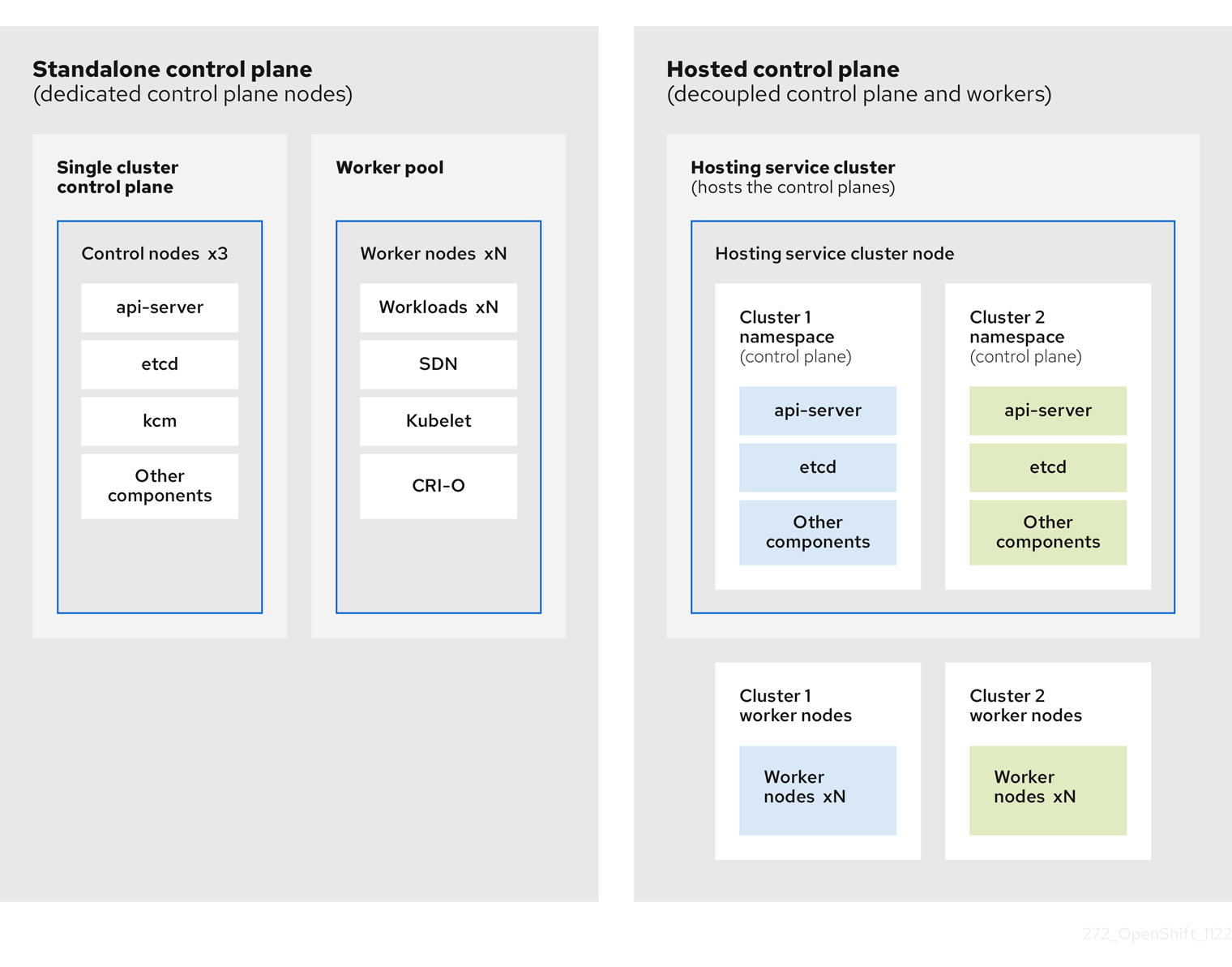
You can deploy OpenShift Container Platform clusters by using two different control plane configurations: standalone or hosted control planes. The standalone configuration uses dedicated virtual machines or physical machines to host the control plane. With hosted control planes for OpenShift Container Platform, you create control planes as pods on a management cluster without the need for dedicated virtual or physical machines for each control plane.
2.1. Introduction to hosted control planes
Hosted control planes is available by using a supported version of multicluster engine for Kubernetes Operator on the following platforms:
- Bare metal by using the Agent provider
- Non-bare-metal Agent machines, as a Technology Preview feature
- OpenShift Virtualization
- Amazon Web Services (AWS)
- IBM Z
- IBM Power
The hosted control planes feature is enabled by default.
The multicluster engine Operator is an integral part of Red Hat Advanced Cluster Management (RHACM) and is enabled by default with RHACM. However, you do not need RHACM in order to use hosted control planes.
2.1.1. Architecture of hosted control planes
OpenShift Container Platform is often deployed in a coupled, or standalone, model, where a cluster consists of a control plane and a data plane. The control plane includes an API endpoint, a storage endpoint, a workload scheduler, and an actuator that ensures state. The data plane includes compute, storage, and networking where workloads and applications run.
The standalone control plane is hosted by a dedicated group of nodes, which can be physical or virtual, with a minimum number to ensure quorum. The network stack is shared. Administrator access to a cluster offers visibility into the cluster’s control plane, machine management APIs, and other components that contribute to the state of a cluster.
Although the standalone model works well, some situations require an architecture where the control plane and data plane are decoupled. In those cases, the data plane is on a separate network domain with a dedicated physical hosting environment. The control plane is hosted by using high-level primitives such as deployments and stateful sets that are native to Kubernetes. The control plane is treated as any other workload.
2.1.2. Benefits of hosted control planes
With hosted control planes, you can pave the way for a true hybrid-cloud approach and enjoy several other benefits.
- The security boundaries between management and workloads are stronger because the control plane is decoupled and hosted on a dedicated hosting service cluster. As a result, you are less likely to leak credentials for clusters to other users. Because infrastructure secret account management is also decoupled, cluster infrastructure administrators cannot accidentally delete control plane infrastructure.
- With hosted control planes, you can run many control planes on fewer nodes. As a result, clusters are more affordable.
- Because the control planes consist of pods that are launched on OpenShift Container Platform, control planes start quickly. The same principles apply to control planes and workloads, such as monitoring, logging, and auto-scaling.
- From an infrastructure perspective, you can push registries, HAProxy, cluster monitoring, storage nodes, and other infrastructure components to the tenant’s cloud provider account, isolating usage to the tenant.
- From an operational perspective, multicluster management is more centralized, which results in fewer external factors that affect the cluster status and consistency. Site reliability engineers have a central place to debug issues and navigate to the cluster data plane, which can lead to shorter Time to Resolution (TTR) and greater productivity.
2.2. Differences between hosted control planes and OpenShift Container Platform
Hosted control planes is a form factor of OpenShift Container Platform. Hosted clusters and the stand-alone OpenShift Container Platform clusters are configured and managed differently. See the following tables to understand the differences between OpenShift Container Platform and hosted control planes:
2.2.1. Cluster creation and lifecycle
| OpenShift Container Platform | Hosted control planes |
|---|---|
|
You install a standalone OpenShift Container Platform cluster by using the |
You install a hosted cluster by using the |
2.2.2. Cluster configuration
| OpenShift Container Platform | Hosted control planes |
|---|---|
|
You configure cluster-scoped resources such as authentication, API server, and proxy by using the |
You configure resources that impact the control plane in the |
2.2.3. etcd encryption
| OpenShift Container Platform | Hosted control planes |
|---|---|
|
You configure etcd encryption by using the |
You configure etcd encryption by using the |
2.2.4. Operators and control plane
| OpenShift Container Platform | Hosted control planes |
|---|---|
| A standalone OpenShift Container Platform cluster contains separate Operators for each control plane component. | A hosted cluster contains a single Operator named Control Plane Operator that runs in the hosted control plane namespace on the management cluster. |
| etcd uses storage that is mounted on the control plane nodes. The etcd cluster Operator manages etcd. | etcd uses a persistent volume claim for storage and is managed by the Control Plane Operator. |
| The Ingress Operator, network related Operators, and Operator Lifecycle Manager (OLM) run on the cluster. | The Ingress Operator, network related Operators, and Operator Lifecycle Manager (OLM) run in the hosted control plane namespace on the management cluster. |
| The OAuth server runs inside the cluster and is exposed through a route in the cluster. | The OAuth server runs inside the control plane and is exposed through a route, node port, or load balancer on the management cluster. |
2.2.5. Updates
| OpenShift Container Platform | Hosted control planes |
|---|---|
|
The Cluster Version Operator (CVO) orchestrates the update process and monitors the |
The hosted control planes update results in a change to the |
| After you update an OpenShift Container Platform cluster, both the control plane and compute machines are updated. | After you update the hosted cluster, only the control plane is updated. You perform node pool updates separately. |
2.2.6. Machine configuration and management
| OpenShift Container Platform | Hosted control planes |
|---|---|
|
The |
The |
| A set of control plane machines are available. | A set of control plane machines do not exist. |
|
You enable a machine health check by using the |
You enable a machine health check through the |
|
You enable autoscaling by using the |
You enable autoscaling through the |
| Machines and machine sets are exposed in the cluster. | Machines, machine sets, and machine deployments from upstream Cluster CAPI Operator are used to manage machines but are not exposed to the user. |
| All machine sets are upgraded automatically when you update the cluster. | You update your node pools independently from the hosted cluster updates. |
| Only an in-place upgrade is supported in the cluster. | Both replace and in-place upgrades are supported in the hosted cluster. |
| The Machine Config Operator manages configurations for machines. | The Machine Config Operator does not exist in hosted control planes. |
|
You configure machine Ignition by using the |
You configure the |
| The Machine Config Daemon (MCD) manages configuration changes and updates on each of the nodes. | For an in-place upgrade, the node pool controller creates a run-once pod that updates a machine based on your configuration. |
| You can modify the machine configuration resources such as the SR-IOV Operator. | You cannot modify the machine configuration resources. |
2.2.7. Networking
| OpenShift Container Platform | Hosted control planes |
|---|---|
| The Kube API server communicates with nodes directly, because the Kube API server and nodes exist in the same Virtual Private Cloud (VPC). | The Kube API server communicates with nodes through Konnectivity. The Kube API server and nodes exist in a different Virtual Private Cloud (VPC). |
| Nodes communicate with the Kube API server through the internal load balancer. | Nodes communicate with the Kube API server through an external load balancer or a node port. |
2.2.8. Web console
| OpenShift Container Platform | Hosted control planes |
|---|---|
| The web console shows the status of a control plane. | The web console does not show the status of a control plane. |
| You can update your cluster by using the web console. | You cannot update the hosted cluster by using the web console. |
| The web console displays the infrastructure resources such as machines. | The web console does not display the infrastructure resources. |
|
You can configure machines through the | You cannot configure machines by using the web console. |
2.3. Relationship between hosted control planes, multicluster engine Operator, and RHACM
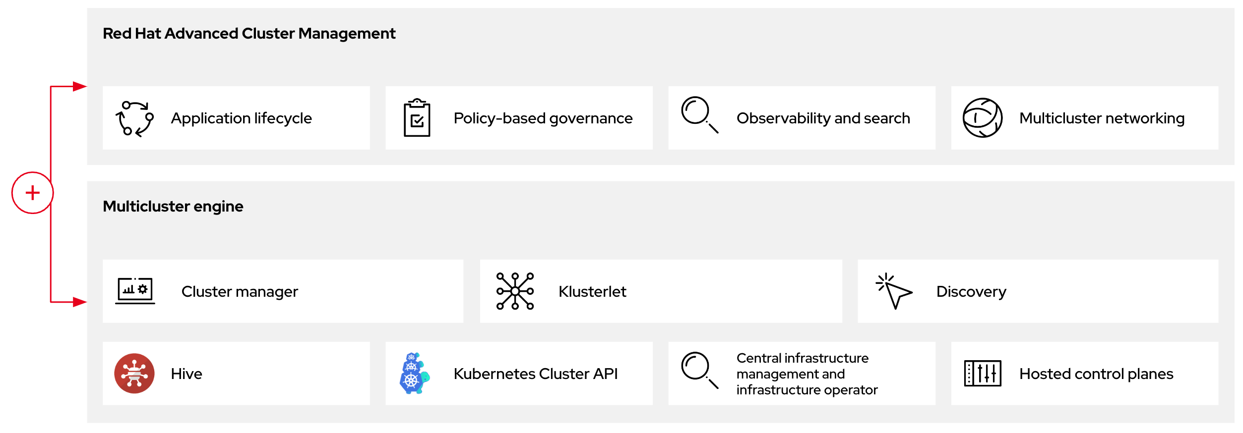
You can configure hosted control planes by using the multicluster engine for Kubernetes Operator. The multicluster engine Operator cluster lifecycle defines the process of creating, importing, managing, and destroying Kubernetes clusters across various infrastructure cloud providers, private clouds, and on-premises data centers.
The multicluster engine Operator is an integral part of Red Hat Advanced Cluster Management (RHACM) and is enabled by default with RHACM. However, you do not need RHACM in order to use hosted control planes.
The multicluster engine Operator is the cluster lifecycle Operator that provides cluster management capabilities for OpenShift Container Platform and RHACM hub clusters. The multicluster engine Operator enhances cluster fleet management and supports OpenShift Container Platform cluster lifecycle management across clouds and data centers.
Figure 2.1. Cluster life cycle and foundation
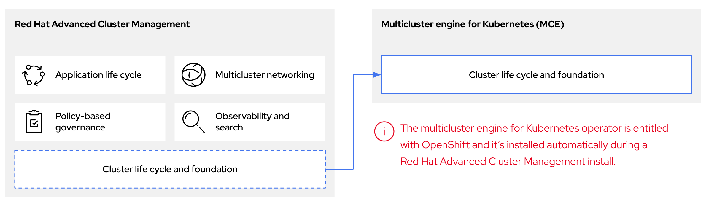
You can use the multicluster engine Operator with OpenShift Container Platform as a standalone cluster manager or as part of a RHACM hub cluster.
A management cluster is also known as the hosting cluster.
You can deploy OpenShift Container Platform clusters by using two different control plane configurations: standalone or hosted control planes. The standalone configuration uses dedicated virtual machines or physical machines to host the control plane. With hosted control planes for OpenShift Container Platform, you create control planes as pods on a management cluster without the need for dedicated virtual or physical machines for each control plane.
Figure 2.2. RHACM and the multicluster engine Operator introduction diagram
2.3.1. Discovering multicluster engine Operator hosted clusters in RHACM
If you want to bring hosted clusters to a Red Hat Advanced Cluster Management (RHACM) hub cluster to manage them with RHACM management components, see the instructions in the Red Hat Advanced Cluster Management official documentation.
2.4. Versioning for hosted control planes
The hosted control planes feature includes the following components, which might require independent versioning and support levels:
- Management cluster
- HyperShift Operator
-
Hosted control planes (
hcp) command-line interface (CLI) -
hypershift.openshift.ioAPI - Control Plane Operator
2.4.1. Management cluster
In management clusters for production use, you need multicluster engine for Kubernetes Operator, which is available through OperatorHub. The multicluster engine Operator bundles a supported build of the HyperShift Operator. For your management clusters to remain supported, you must use the version of OpenShift Container Platform that multicluster engine Operator runs on. In general, a new release of multicluster engine Operator runs on the following versions of OpenShift Container Platform:
- The latest General Availability version of OpenShift Container Platform
- Two versions before the latest General Availability version of OpenShift Container Platform
The full list of OpenShift Container Platform versions that you can install through the HyperShift Operator on a management cluster depends on the version of your HyperShift Operator. However, the list always includes at least the same OpenShift Container Platform version as the management cluster and two previous minor versions relative to the management cluster. For example, if the management cluster is running 4.17 and a supported version of multicluster engine Operator, the HyperShift Operator can install 4.17, 4.16, 4.15, and 4.14 hosted clusters.
With each major, minor, or patch version release of OpenShift Container Platform, two components of hosted control planes are released:
- The HyperShift Operator
-
The
hcpcommand-line interface (CLI)
2.4.2. HyperShift Operator
The HyperShift Operator manages the lifecycle of hosted clusters that are represented by the HostedCluster API resources. The HyperShift Operator is released with each OpenShift Container Platform release. The HyperShift Operator creates the supported-versions config map in the hypershift namespace. The config map contains the supported hosted cluster versions.
You can host different versions of control planes on the same management cluster.
Example supported-versions config map object
apiVersion: v1
data:
supported-versions: '{"versions":["4.17"]}'
kind: ConfigMap
metadata:
labels:
hypershift.openshift.io/supported-versions: "true"
name: supported-versions
namespace: hypershift2.4.3. hosted control planes CLI
You can use the hcp CLI to create hosted clusters. You can download the CLI from multicluster engine Operator. When you run the hcp version command, the output shows the latest OpenShift Container Platform that the CLI supports against your kubeconfig file.
2.4.4. hypershift.openshift.io API
You can use the hypershift.openshift.io API resources, such as, HostedCluster and NodePool, to create and manage OpenShift Container Platform clusters at scale. A HostedCluster resource contains the control plane and common data plane configuration. When you create a HostedCluster resource, you have a fully functional control plane with no attached nodes. A NodePool resource is a scalable set of worker nodes that is attached to a HostedCluster resource.
The API version policy generally aligns with the policy for Kubernetes API versioning.
Updates for hosted control planes involve updating the hosted cluster and the node pools. For more information, see "Updates for hosted control planes".
2.4.5. Control Plane Operator
The Control Plane Operator is released as part of each OpenShift Container Platform payload release image for the following architectures:
- amd64
- arm64
- multi-arch
2.5. Glossary of common concepts and personas for hosted control planes
When you use hosted control planes for OpenShift Container Platform, it is important to understand its key concepts and the personas that are involved.
2.5.1. Concepts
- data plane
- The part of the cluster that includes the compute, storage, and networking where workloads and applications run.
- hosted cluster
- An OpenShift Container Platform cluster with its control plane and API endpoint hosted on a management cluster. The hosted cluster includes the control plane and its corresponding data plane.
- hosted cluster infrastructure
- Network, compute, and storage resources that exist in the tenant or end-user cloud account.
- hosted control plane
- An OpenShift Container Platform control plane that runs on the management cluster, which is exposed by the API endpoint of a hosted cluster. The components of a control plane include etcd, the Kubernetes API server, the Kubernetes controller manager, and a VPN.
- hosting cluster
- See management cluster.
- managed cluster
- A cluster that the hub cluster manages. This term is specific to the cluster lifecycle that the multicluster engine for Kubernetes Operator manages in Red Hat Advanced Cluster Management. A managed cluster is not the same thing as a management cluster. For more information, see Managed cluster.
- management cluster
- An OpenShift Container Platform cluster where the HyperShift Operator is deployed and where the control planes for hosted clusters are hosted. The management cluster is synonymous with the hosting cluster.
- management cluster infrastructure
- Network, compute, and storage resources of the management cluster.
- node pool
- A resource that manages a set of compute nodes that are associated with a hosted cluster. The compute nodes run applications and workloads within the hosted cluster.
2.5.2. Personas
- cluster instance administrator
-
Users who assume this role are the equivalent of administrators in standalone OpenShift Container Platform. This user has the
cluster-adminrole in the provisioned cluster, but might not have power over when or how the cluster is updated or configured. This user might have read-only access to see some configuration projected into the cluster. - cluster instance user
- Users who assume this role are the equivalent of developers in standalone OpenShift Container Platform. This user does not have a view into OperatorHub or machines.
- cluster service consumer
- Users who assume this role can request control planes and worker nodes, drive updates, or modify externalized configurations. Typically, this user does not manage or access cloud credentials or infrastructure encryption keys. The cluster service consumer persona can request hosted clusters and interact with node pools. Users who assume this role have RBAC to create, read, update, or delete hosted clusters and node pools within a logical boundary.
- cluster service provider
Users who assume this role typically have the
cluster-adminrole on the management cluster and have RBAC to monitor and own the availability of the HyperShift Operator as well as the control planes for the tenant’s hosted clusters. The cluster service provider persona is responsible for several activities, including the following examples:- Owning service-level objects for control plane availability, uptime, and stability
- Configuring the cloud account for the management cluster to host control planes
- Configuring the user-provisioned infrastructure, which includes the host awareness of available compute resources
Chapter 3. Preparing to deploy hosted control planes
3.1. Requirements for hosted control planes
In the context of hosted control planes, a management cluster is an OpenShift Container Platform cluster where the HyperShift Operator is deployed and where the control planes for hosted clusters are hosted.
The control plane is associated with a hosted cluster and runs as pods in a single namespace. When the cluster service consumer creates a hosted cluster, it creates a worker node that is independent of the control plane.
The following requirements apply to hosted control planes:
- In order to run the HyperShift Operator, your management cluster needs at least three worker nodes.
- You can run both the management cluster and the worker nodes on-premise, such as on a bare-metal platform or on OpenShift Virtualization. In addition, you can run both the management cluster and the worker nodes on cloud infrastructure, such as Amazon Web Services (AWS).
-
If you use a mixed infrastructure, such as running the management cluster on AWS and your worker nodes on-premise, or running your worker nodes on AWS and your management cluster on-premise, you must use the
PublicAndPrivatepublishing strategy and follow the latency requirements in the support matrix. - In Bare Metal Host (BMH) deployments, where the Bare Metal Operator starts machines, the hosted control plane must be able to reach baseboard management controllers (BMCs). If your security profile does not permit the Cluster Baremetal Operator to access the network where the BMHs have their BMCs in order to enable Redfish automation, you can use BYO ISO support. However, in BYO mode, OpenShift Container Platform cannot automate the powering on of BMHs.
3.1.1. Support matrix for hosted control planes
Because multicluster engine for Kubernetes Operator includes the HyperShift Operator, releases of hosted control planes align with releases of multicluster engine Operator. For more information, see OpenShift Operator Life Cycles.
3.1.1.1. Management cluster support
Any supported OpenShift Container Platform cluster can be a management cluster.
A single-node OpenShift Container Platform cluster is not supported as a management cluster. If you have resource constraints, you can share infrastructure between a standalone OpenShift Container Platform control plane and hosted control planes. For more information, see "Shared infrastructure between hosted and standalone control planes".
The following table maps multicluster engine Operator versions to the management cluster versions that support them:
| Management cluster version | Supported multicluster engine Operator version |
|---|---|
| 4.14 - 4.15 | 2.4 |
| 4.14 - 4.16 | 2.5 |
| 4.14 - 4.17 | 2.6 |
| 4.15 - 4.17 | 2.7 |
3.1.1.2. Hosted cluster support
For hosted clusters, no direct relationship exists between the management cluster version and the hosted cluster version. The hosted cluster version depends on the HyperShift Operator that is included with your multicluster engine Operator version.
Ensure a maximum latency of 200 ms between the management cluster and hosted clusters. This requirement is especially important for mixed infrastructure deployments, such as when your management cluster is on AWS and your worker nodes are on-premise.
The following table maps multicluster engine Operator versions to the hosted cluster versions that you can create by using the HyperShift Operator that is associated with that version of multicluster engine Operator:
| Hosted cluster version | multicluster engine Operator 2.4 | multicluster engine Operator 2.5 | multicluster engine Operator 2.6 | multicluster engine Operator 2.7 |
|---|---|---|---|---|
| 4.14 | Yes | Yes | Yes | Yes |
| 4.15 | No | Yes | Yes | Yes |
| 4.16 | No | No | Yes | Yes |
| 4.17 | No | No | No | Yes |
3.1.1.3. Hosted cluster platform support
The following table indicates which OpenShift Container Platform versions are supported for each platform of hosted control planes.
For IBM Power and IBM Z, you must run the control plane on machine types based on 64-bit x86 architecture, and node pools on IBM Power or IBM Z.
In the following table, Management cluster version refers to the OpenShift Container Platform version where the multicluster engine Operator is enabled:
| Hosted cluster platform | Management cluster version | Hosted cluster version |
|---|---|---|
| Amazon Web Services | 4.16 - 4.17 | 4.16 - 4.17 |
| IBM Power | 4.17 | 4.17 |
| IBM Z | 4.17 | 4.17 |
| OpenShift Virtualization | 4.14 - 4.17 | 4.14 - 4.17 |
| Bare metal | 4.14 - 4.17 | 4.14 - 4.17 |
| Non-bare-metal agent machines (Technology Preview) | 4.16 - 4.17 | 4.16 - 4.17 |
3.1.1.4. Updates of multicluster engine Operator
When you update to another version of the multicluster engine Operator, your hosted cluster can continue to run if the HyperShift Operator that is included in the version of multicluster engine Operator supports the hosted cluster version. The following table shows which hosted cluster versions are supported on which updated multicluster engine Operator versions:
| Updated multicluster engine Operator version | Supported hosted cluster version |
|---|---|
| Updated from 2.4 to 2.5 | OpenShift Container Platform 4.14 |
| Updated from 2.5 to 2.6 | OpenShift Container Platform 4.14 - 4.15 |
| Updated from 2.6 to 2.7 | OpenShift Container Platform 4.14 - 4.16 |
For example, if you have an OpenShift Container Platform 4.14 hosted cluster on the management cluster and you update from multicluster engine Operator 2.4 to 2.5, the hosted cluster can continue to run.
3.1.1.5. Technology Preview features
The following list indicates Technology Preview features for this release:
- Hosted control planes on IBM Z in a disconnected environment
- Custom taints and tolerations for hosted control planes
- NVIDIA GPU devices on hosted control planes for OpenShift Virtualization
3.1.2. CIDR ranges for hosted control planes
The following Classless Inter-Domain Routing (CIDR) subnet ranges are the default settings for hosted control planes:
-
v4InternalSubnet: 100.65.0.0/16 (OVN-Kubernetes) -
clusterNetwork: 10.132.0.0/14 (pod network) -
serviceNetwork: 172.31.0.0/16
By using one of the default subnet ranges, you can avoid CIDR overlap with the management cluster and avoid connectivity issues. However, you can use other CIDR subnet ranges if they do not overlap with the management cluster.
For more information about OpenShift Container Platform CIDR range definitions, see "CIDR range definitions".
3.2. Sizing guidance for hosted control planes
Many factors, including hosted cluster workload and worker node count, affect how many hosted control planes can fit within a certain number of worker nodes. Use this sizing guide to help with hosted cluster capacity planning. This guidance assumes a highly available hosted control planes topology. The load-based sizing examples were measured on a bare-metal cluster. Cloud-based instances might have different limiting factors, such as memory size.
You can override the following resource utilization sizing measurements and disable the metric service monitoring.
See the following highly available hosted control planes requirements, which were tested with OpenShift Container Platform version 4.12.9 and later:
- 78 pods
- Three 8 GiB PVs for etcd
- Minimum vCPU: approximately 5.5 cores
- Minimum memory: approximately 19 GiB
3.2.1. Pod limits
The maxPods setting for each node affects how many hosted clusters can fit in a control-plane node. It is important to note the maxPods value on all control-plane nodes. Plan for about 75 pods for each highly available hosted control plane.
For bare-metal nodes, the default maxPods setting of 250 is likely to be a limiting factor because roughly three hosted control planes fit for each node given the pod requirements, even if the machine has plenty of resources to spare. Setting the maxPods value to 500 by configuring the KubeletConfig value allows for greater hosted control plane density, which can help you take advantage of additional compute resources.
3.2.2. Request-based resource limit
The maximum number of hosted control planes that the cluster can host is calculated based on the hosted control plane CPU and memory requests from the pods.
A highly available hosted control plane consists of 78 pods that request 5 vCPUs and 18 GiB memory. These baseline numbers are compared to the cluster worker node resource capacities to estimate the maximum number of hosted control planes.
3.2.3. Load-based limit
The maximum number of hosted control planes that the cluster can host is calculated based on the hosted control plane pods CPU and memory utilizations when some workload is put on the hosted control plane Kubernetes API server.
The following method is used to measure the hosted control plane resource utilizations as the workload increases:
- A hosted cluster with 9 workers that use 8 vCPU and 32 GiB each, while using the KubeVirt platform
The workload test profile that is configured to focus on API control-plane stress, based on the following definition:
- Created objects for each namespace, scaling up to 100 namespaces total
- Additional API stress with continuous object deletion and creation
- Workload queries-per-second (QPS) and Burst settings set high to remove any client-side throttling
As the load increases by 1000 QPS, the hosted control plane resource utilization increases by 9 vCPUs and 2.5 GB memory.
For general sizing purposes, consider the 1000 QPS API rate that is a medium hosted cluster load, and a 2000 QPS API that is a heavy hosted cluster load.
This test provides an estimation factor to increase the compute resource utilization based on the expected API load. Exact utilization rates can vary based on the type and pace of the cluster workload.
The following example shows hosted control plane resource scaling for the workload and API rate definitions:
| QPS (API rate) | vCPU usage | Memory usage (GiB) |
|---|---|---|
| Low load (Less than 50 QPS) | 2.9 | 11.1 |
| Medium load (1000 QPS) | 11.9 | 13.6 |
| High load (2000 QPS) | 20.9 | 16.1 |
The hosted control plane sizing is about control-plane load and workloads that cause heavy API activity, etcd activity, or both. Hosted pod workloads that focus on data-plane loads, such as running a database, might not result in high API rates.
3.2.4. Sizing calculation example
This example provides sizing guidance for the following scenario:
-
Three bare-metal workers that are labeled as
hypershift.openshift.io/control-planenodes -
maxPodsvalue set to 500 - The expected API rate is medium or about 1000, according to the load-based limits
| Limit description | Server 1 | Server 2 |
|---|---|---|
| Number of vCPUs on worker node | 64 | 128 |
| Memory on worker node (GiB) | 128 | 256 |
| Maximum pods per worker | 500 | 500 |
| Number of workers used to host control planes | 3 | 3 |
| Maximum QPS target rate (API requests per second) | 1000 | 1000 |
| Calculated values based on worker node size and API rate | Server 1 | Server 2 | Calculation notes |
| Maximum hosted control planes per worker based on vCPU requests | 12.8 | 25.6 | Number of worker vCPUs ÷ 5 total vCPU requests per hosted control plane |
| Maximum hosted control planes per worker based on vCPU usage | 5.4 | 10.7 | Number of vCPUS ÷ (2.9 measured idle vCPU usage + (QPS target rate ÷ 1000) × 9.0 measured vCPU usage per 1000 QPS increase) |
| Maximum hosted control planes per worker based on memory requests | 7.1 | 14.2 | Worker memory GiB ÷ 18 GiB total memory request per hosted control plane |
| Maximum hosted control planes per worker based on memory usage | 9.4 | 18.8 | Worker memory GiB ÷ (11.1 measured idle memory usage + (QPS target rate ÷ 1000) × 2.5 measured memory usage per 1000 QPS increase) |
| Maximum hosted control planes per worker based on per node pod limit | 6.7 | 6.7 |
500 |
| Minimum of previously mentioned maximums | 5.4 | 6.7 | |
| vCPU limiting factor |
| ||
| Maximum number of hosted control planes within a management cluster | 16 | 20 | Minimum of previously mentioned maximums × 3 control-plane workers |
| Name | Description |
|
| Estimated maximum number of hosted control planes the cluster can host based on a highly available hosted control planes resource request. |
|
| Estimated maximum number of hosted control planes the cluster can host if all hosted control planes make around 50 QPS to the clusters Kube API server. |
|
| Estimated maximum number of hosted control planes the cluster can host if all hosted control planes make around 1000 QPS to the clusters Kube API server. |
|
| Estimated maximum number of hosted control planes the cluster can host if all hosted control planes make around 2000 QPS to the clusters Kube API server. |
|
| Estimated maximum number of hosted control planes the cluster can host based on the existing average QPS of hosted control planes. If you do not have an active hosted control planes, you can expect low QPS. |
3.3. Overriding resource utilization measurements
The set of baseline measurements for resource utilization can vary in each hosted cluster.
3.3.1. Overriding resource utilization measurements for a hosted cluster
You can override resource utilization measurements based on the type and pace of your cluster workload.
Procedure
Create the
ConfigMapresource by running the following command:$ oc create -f <your-config-map-file.yaml>Replace
<your-config-map-file.yaml>with the name of your YAML file that contains yourhcp-sizing-baselineconfig map.Create the
hcp-sizing-baselineconfig map in thelocal-clusternamespace to specify the measurements you want to override. Your config map might resemble the following YAML file:kind: ConfigMap apiVersion: v1 metadata: name: hcp-sizing-baseline namespace: local-cluster data: incrementalCPUUsagePer1KQPS: "9.0" memoryRequestPerHCP: "18" minimumQPSPerHCP: "50.0"Delete the
hypershift-addon-agentdeployment to restart thehypershift-addon-agentpod by running the following command:$ oc delete deployment hypershift-addon-agent \ -n open-cluster-management-agent-addon
Verification
Observe the
hypershift-addon-agentpod logs. Verify that the overridden measurements are updated in the config map by running the following command:$ oc logs hypershift-addon-agent -n open-cluster-management-agent-addonYour logs might resemble the following output:
Example output
2024-01-05T19:41:05.392Z INFO agent.agent-reconciler agent/agent.go:793 setting cpuRequestPerHCP to 5 2024-01-05T19:41:05.392Z INFO agent.agent-reconciler agent/agent.go:802 setting memoryRequestPerHCP to 18 2024-01-05T19:53:54.070Z INFO agent.agent-reconciler agent/hcp_capacity_calculation.go:141 The worker nodes have 12.000000 vCPUs 2024-01-05T19:53:54.070Z INFO agent.agent-reconciler agent/hcp_capacity_calculation.go:142 The worker nodes have 49.173369 GB memoryIf the overridden measurements are not updated properly in the
hcp-sizing-baselineconfig map, you might see the following error message in thehypershift-addon-agentpod logs:Example error
2024-01-05T19:53:54.052Z ERROR agent.agent-reconciler agent/agent.go:788 failed to get configmap from the hub. Setting the HCP sizing baseline with default values. {"error": "configmaps \"hcp-sizing-baseline\" not found"}
3.3.2. Disabling the metric service monitoring
After you enable the hypershift-addon managed cluster add-on, metric service monitoring is configured by default so that OpenShift Container Platform monitoring can gather metrics from hypershift-addon.
Procedure
You can disable metric service monitoring by completing the following steps:
Log in to your hub cluster by running the following command:
$ oc loginEdit the
hypershift-addon-deploy-configadd-on deployment configuration specification by running the following command:$ oc edit addondeploymentconfig hypershift-addon-deploy-config \ -n multicluster-engineAdd the
disableMetrics=truecustomized variable to the specification, as shown in the following example:apiVersion: addon.open-cluster-management.io/v1alpha1 kind: AddOnDeploymentConfig metadata: name: hypershift-addon-deploy-config namespace: multicluster-engine spec: customizedVariables: - name: hcMaxNumber value: "80" - name: hcThresholdNumber value: "60" - name: disableMetrics1 value: "true"- 1
- The
disableMetrics=truecustomized variable disables metric service monitoring for both new and existinghypershift-addonmanaged cluster add-ons.
Apply the changes to the configuration specification by running the following command:
$ oc apply -f <filename>.yaml
3.4. Installing the hosted control planes command-line interface
The hosted control planes command-line interface, hcp, is a tool that you can use to get started with hosted control planes. For Day 2 operations, such as management and configuration, use GitOps or your own automation tool.
3.4.1. Installing the hosted control planes command-line interface from the terminal
You can install the hosted control planes command-line interface (CLI), hcp, from the terminal.
Prerequisites
- On an OpenShift Container Platform cluster, you have installed multicluster engine for Kubernetes Operator 2.5 or later. The multicluster engine Operator is automatically installed when you install Red Hat Advanced Cluster Management. You can also install multicluster engine Operator without Red Hat Advanced Management as an Operator from OpenShift Container Platform OperatorHub.
Procedure
Get the URL to download the
hcpbinary by running the following command:$ oc get ConsoleCLIDownload hcp-cli-download -o json | jq -r ".spec"Download the
hcpbinary by running the following command:$ wget <hcp_cli_download_url>1 - 1
- Replace
hcp_cli_download_urlwith the URL that you obtained from the previous step.
Unpack the downloaded archive by running the following command:
$ tar xvzf hcp.tar.gzMake the
hcpbinary file executable by running the following command:$ chmod +x hcpMove the
hcpbinary file to a directory in your path by running the following command:$ sudo mv hcp /usr/local/bin/.
If you download the CLI on a Mac computer, you might see a warning about the hcp binary file. You need to adjust your security settings to allow the binary file to be run.
Verification
Verify that you see the list of available parameters by running the following command:
$ hcp create cluster <platform> --help1 - 1
- You can use the
hcp create clustercommand to create and manage hosted clusters. The supported platforms areaws,agent, andkubevirt.
3.4.2. Installing the hosted control planes command-line interface by using the web console
You can install the hosted control planes command-line interface (CLI), hcp, by using the OpenShift Container Platform web console.
Prerequisites
- On an OpenShift Container Platform cluster, you have installed multicluster engine for Kubernetes Operator 2.5 or later. The multicluster engine Operator is automatically installed when you install Red Hat Advanced Cluster Management. You can also install multicluster engine Operator without Red Hat Advanced Management as an Operator from OpenShift Container Platform OperatorHub.
Procedure
- From the OpenShift Container Platform web console, click the Help icon → Command Line Tools.
- Click Download hcp CLI for your platform.
Unpack the downloaded archive by running the following command:
$ tar xvzf hcp.tar.gzRun the following command to make the binary file executable:
$ chmod +x hcpRun the following command to move the binary file to a directory in your path:
$ sudo mv hcp /usr/local/bin/.
If you download the CLI on a Mac computer, you might see a warning about the hcp binary file. You need to adjust your security settings to allow the binary file to be run.
Verification
Verify that you see the list of available parameters by running the following command:
$ hcp create cluster <platform> --help1 - 1
- You can use the
hcp create clustercommand to create and manage hosted clusters. The supported platforms areaws,agent, andkubevirt.
3.4.3. Installing the hosted control planes command-line interface by using the content gateway
You can install the hosted control planes command-line interface (CLI), hcp, by using the content gateway.
Prerequisites
- On an OpenShift Container Platform cluster, you have installed multicluster engine for Kubernetes Operator 2.5 or later. The multicluster engine Operator is automatically installed when you install Red Hat Advanced Cluster Management. You can also install multicluster engine Operator without Red Hat Advanced Management as an Operator from OpenShift Container Platform OperatorHub.
Procedure
-
Navigate to the content gateway and download the
hcpbinary. Unpack the downloaded archive by running the following command:
$ tar xvzf hcp.tar.gzMake the
hcpbinary file executable by running the following command:$ chmod +x hcpMove the
hcpbinary file to a directory in your path by running the following command:$ sudo mv hcp /usr/local/bin/.
If you download the CLI on a Mac computer, you might see a warning about the hcp binary file. You need to adjust your security settings to allow the binary file to be run.
Verification
Verify that you see the list of available parameters by running the following command:
$ hcp create cluster <platform> --help1 - 1
- You can use the
hcp create clustercommand to create and manage hosted clusters. The supported platforms areaws,agent, andkubevirt.
3.5. Distributing hosted cluster workloads
Before you get started with hosted control planes for OpenShift Container Platform, you must properly label nodes so that the pods of hosted clusters can be scheduled into infrastructure nodes. Node labeling is also important for the following reasons:
-
To ensure high availability and proper workload deployment. For example, you can set the
node-role.kubernetes.io/infralabel to avoid having the control-plane workload count toward your OpenShift Container Platform subscription. - To ensure that control plane workloads are separate from other workloads in the management cluster.
Do not use the management cluster for your workload. Workloads must not run on nodes where control planes run.
3.5.1. Labeling management cluster nodes
Proper node labeling is a prerequisite to deploying hosted control planes.
As a management cluster administrator, you use the following labels and taints in management cluster nodes to schedule a control plane workload:
-
hypershift.openshift.io/control-plane: true: Use this label and taint to dedicate a node to running hosted control plane workloads. By setting a value oftrue, you avoid sharing the control plane nodes with other components, for example, the infrastructure components of the management cluster or any other mistakenly deployed workload. -
hypershift.openshift.io/cluster: ${HostedControlPlane Namespace}: Use this label and taint when you want to dedicate a node to a single hosted cluster.
Apply the following labels on the nodes that host control-plane pods:
-
node-role.kubernetes.io/infra: Use this label to avoid having the control-plane workload count toward your subscription. topology.kubernetes.io/zone: Use this label on the management cluster nodes to deploy highly available clusters across failure domains. The zone might be a location, rack name, or the hostname of the node where the zone is set. For example, a management cluster has the following nodes:worker-1a,worker-1b,worker-2a, andworker-2b. Theworker-1aandworker-1bnodes are inrack1, and theworker-2aand worker-2b nodes are inrack2. To use each rack as an availability zone, enter the following commands:$ oc label node/worker-1a node/worker-1b topology.kubernetes.io/zone=rack1$ oc label node/worker-2a node/worker-2b topology.kubernetes.io/zone=rack2
Pods for a hosted cluster have tolerations, and the scheduler uses affinity rules to schedule them. Pods tolerate taints for control-plane and the cluster for the pods. The scheduler prioritizes the scheduling of pods into nodes that are labeled with hypershift.openshift.io/control-plane and hypershift.openshift.io/cluster: ${HostedControlPlane Namespace}.
For the ControllerAvailabilityPolicy option, use HighlyAvailable, which is the default value that the hosted control planes command-line interface, hcp, deploys. When you use that option, you can schedule pods for each deployment within a hosted cluster across different failure domains by setting topology.kubernetes.io/zone as the topology key. Scheduling pods for a deployment within a hosted cluster across different failure domains is available only for highly available control planes.
Procedure
To enable a hosted cluster to require its pods to be scheduled into infrastructure nodes, set HostedCluster.spec.nodeSelector, as shown in the following example:
spec:
nodeSelector:
node-role.kubernetes.io/infra: ""This way, hosted control planes for each hosted cluster are eligible infrastructure node workloads, and you do not need to entitle the underlying OpenShift Container Platform nodes.
3.5.2. Priority classes
Four built-in priority classes influence the priority and preemption of the hosted cluster pods. You can create the pods in the management cluster in the following order from highest to lowest:
-
hypershift-operator: HyperShift Operator pods. -
hypershift-etcd: Pods for etcd. -
hypershift-api-critical: Pods that are required for API calls and resource admission to succeed. These pods include pods such askube-apiserver, aggregated API servers, and web hooks. -
hypershift-control-plane: Pods in the control plane that are not API-critical but still need elevated priority, such as the cluster version Operator.
3.5.3. Custom taints and tolerations
By default, pods for a hosted cluster tolerate the control-plane and cluster taints. However, you can also use custom taints on nodes so that hosted clusters can tolerate those taints on a per-hosted-cluster basis by setting HostedCluster.spec.tolerations.
Passing tolerations for a hosted cluster is a Technology Preview feature only. Technology Preview features are not supported with Red Hat production service level agreements (SLAs) and might not be functionally complete. Red Hat does not recommend using them in production. These features provide early access to upcoming product features, enabling customers to test functionality and provide feedback during the development process.
For more information about the support scope of Red Hat Technology Preview features, see Technology Preview Features Support Scope.
Example configuration
spec:
tolerations:
- effect: NoSchedule
key: kubernetes.io/custom
operator: Exists
You can also set tolerations on the hosted cluster while you create a cluster by using the --tolerations hcp CLI argument.
Example CLI argument
--toleration="key=kubernetes.io/custom,operator=Exists,effect=NoSchedule"
For fine granular control of hosted cluster pod placement on a per-hosted-cluster basis, use custom tolerations with nodeSelectors. You can co-locate groups of hosted clusters and isolate them from other hosted clusters. You can also place hosted clusters in infra and control plane nodes.
Tolerations on the hosted cluster spread only to the pods of the control plane. To configure other pods that run on the management cluster and infrastructure-related pods, such as the pods to run virtual machines, you need to use a different process.
3.6. Enabling or disabling the hosted control planes feature
The hosted control planes feature, as well as the hypershift-addon managed cluster add-on, are enabled by default. If you want to disable the feature, or if you disabled it and want to manually enable it, see the following procedures.
3.6.1. Manually enabling the hosted control planes feature
If you need to manually enable hosted control planes, complete the following steps.
Procedure
Run the following command to enable the feature:
$ oc patch mce multiclusterengine --type=merge -p \ '{"spec":{"overrides":{"components":[{"name":"hypershift","enabled": true}]}}}'1 - 1
- The default
MultiClusterEngineresource instance name ismulticlusterengine, but you can get theMultiClusterEnginename from your cluster by running the following command:$ oc get mce.
Run the following command to verify that the
hypershiftandhypershift-local-hostingfeatures are enabled in theMultiClusterEnginecustom resource:$ oc get mce multiclusterengine -o yaml1 - 1
- The default
MultiClusterEngineresource instance name ismulticlusterengine, but you can get theMultiClusterEnginename from your cluster by running the following command:$ oc get mce.
Example output
apiVersion: multicluster.openshift.io/v1 kind: MultiClusterEngine metadata: name: multiclusterengine spec: overrides: components: - name: hypershift enabled: true - name: hypershift-local-hosting enabled: true
3.6.1.1. Manually enabling the hypershift-addon managed cluster add-on for local-cluster
Enabling the hosted control planes feature automatically enables the hypershift-addon managed cluster add-on. If you need to enable the hypershift-addon managed cluster add-on manually, complete the following steps to use the hypershift-addon to install the HyperShift Operator on local-cluster.
Procedure
Create the
ManagedClusterAddonadd-on namedhypershift-addonby creating a file that resembles the following example:apiVersion: addon.open-cluster-management.io/v1alpha1 kind: ManagedClusterAddOn metadata: name: hypershift-addon namespace: local-cluster spec: installNamespace: open-cluster-management-agent-addonApply the file by running the following command:
$ oc apply -f <filename>Replace
filenamewith the name of the file that you created.Confirm that the
hypershift-addonmanaged cluster add-on is installed by running the following command:$ oc get managedclusteraddons -n local-cluster hypershift-addonIf the add-on is installed, the output resembles the following example:
NAME AVAILABLE DEGRADED PROGRESSING hypershift-addon True
Your hypershift-addon managed cluster add-on is installed and the hosting cluster is available to create and manage hosted clusters.
3.6.2. Disabling the hosted control planes feature
You can uninstall the HyperShift Operator and disable the hosted control planes feature. When you disable the hosted control planes feature, you must destroy the hosted cluster and the managed cluster resource on multicluster engine Operator, as described in the Managing hosted clusters topics.
3.6.2.1. Uninstalling the HyperShift Operator
To uninstall the HyperShift Operator and disable the hypershift-addon from the local-cluster, complete the following steps:
Procedure
Run the following command to ensure that there is no hosted cluster running:
$ oc get hostedcluster -AImportantIf a hosted cluster is running, the HyperShift Operator does not uninstall, even if the
hypershift-addonis disabled.Disable the
hypershift-addonby running the following command:$ oc patch mce multiclusterengine --type=merge -p \1 '{"spec":{"overrides":{"components":[{"name":"hypershift-local-hosting","enabled": false}]}}}'- 1
- The default
MultiClusterEngineresource instance name ismulticlusterengine, but you can get theMultiClusterEnginename from your cluster by running the following command:$ oc get mce.
NoteYou can also disable the
hypershift-addonfor thelocal-clusterfrom the multicluster engine Operator console after disabling thehypershift-addon.
3.6.2.2. Disabling the hosted control planes feature
To disable the hosted control planes feature, complete the following steps.
Prerequisites
- You uninstalled the HyperShift Operator. For more information, see "Uninstalling the HyperShift Operator".
Procedure
Run the following command to disable the hosted control planes feature:
$ oc patch mce multiclusterengine --type=merge -p \1 '{"spec":{"overrides":{"components":[{"name":"hypershift","enabled": false}]}}}'- 1
- The default
MultiClusterEngineresource instance name ismulticlusterengine, but you can get theMultiClusterEnginename from your cluster by running the following command:$ oc get mce.
You can verify that the
hypershiftandhypershift-local-hostingfeatures are disabled in theMultiClusterEnginecustom resource by running the following command:$ oc get mce multiclusterengine -o yaml1 - 1
- The default
MultiClusterEngineresource instance name ismulticlusterengine, but you can get theMultiClusterEnginename from your cluster by running the following command:$ oc get mce.
See the following example where
hypershiftandhypershift-local-hostinghave theirenabled:flags set tofalse:apiVersion: multicluster.openshift.io/v1 kind: MultiClusterEngine metadata: name: multiclusterengine spec: overrides: components: - name: hypershift enabled: false - name: hypershift-local-hosting enabled: false
Chapter 4. Deploying hosted control planes
4.1. Deploying hosted control planes on AWS
To reduce infrastructure costs and improve cluster management efficiency, you can deploy hosted control planes on AWS. This configuration decouples the control plane from the data plane so that you can manage multiple clusters from a central management service.
A hosted cluster is an OpenShift Container Platform cluster with its API endpoint and control plane that are hosted on the management cluster. The hosted cluster includes the control plane and its corresponding data plane. To configure hosted control planes on premises, you must install multicluster engine for Kubernetes Operator in a management cluster. By deploying the HyperShift Operator on an existing managed cluster by using the hypershift-addon managed cluster add-on, you can enable that cluster as a management cluster and start to create the hosted cluster. The hypershift-addon managed cluster add-on is enabled by default for the local-cluster managed cluster.
You can use the multicluster engine Operator console or the hosted control plane command-line interface (CLI), hcp, to create a hosted cluster. The hosted cluster is automatically imported as a managed cluster. However, you can disable this automatic import feature into multicluster engine Operator.
4.1.1. Preparing to deploy hosted control planes on AWS
Preparing to deploy hosted control planes on Amazon Web Services (AWS) involves meeting several prerequisites and creating resources, including an S3 bucket, an OIDC secret, a routable public zone, IAM role and STS credentials.
4.1.1.1. Prerequisites to deploy hosted control planes on AWS
To ensure successful deployment of hosted control planes on Amazon Web Services (AWS), your environment must meet the following requirements.
- You have installed the multicluster engine for Kubernetes Operator 2.5 and later on an OpenShift Container Platform cluster. The multicluster engine Operator is automatically installed when you install Red Hat Advanced Cluster Management (RHACM). The multicluster engine Operator can also be installed without RHACM as an Operator from the OpenShift Container Platform OperatorHub.
You have at least one managed OpenShift Container Platform cluster for the multicluster engine Operator. The
local-clusteris automatically imported in the multicluster engine Operator version 2.5 and later. You can check the status of your hub cluster by running the following command:$ oc get managedclusters local-cluster-
You installed the
awscommand-line interface (CLI). -
You installed the hosted control plane CLI,
hcp.
- Run the management cluster and compute nodes on the same platform.
- For each hosted cluster, provide a cluster-wide unique name. A hosted cluster name cannot be the same as any existing managed cluster in order for multicluster engine Operator to manage it.
-
Do not use
clustersas a hosted cluster name. - Do not create a hosted cluster in the namespace of a multicluster engine Operator managed cluster.
4.1.1.2. Creating the Amazon Web Services S3 bucket and S3 OIDC secret
Before you can create and manage a hosted cluster on Amazon Web Services (AWS), you must create the S3 bucket and S3 OIDC secret. These resources provide a place for the cluster to store information about itself and a way for the cluster to prove its identity to AWS.
Procedure
Create an S3 bucket that has public access to host OIDC discovery documents for your clusters.
Enter the following command:
$ aws s3api create-bucket --bucket <bucket_name> \ --create-bucket-configuration LocationConstraint=<region> \ --region <region>1 where:
<bucket_name>- Specifies the name of the S3 bucket you are creating.
<region>-
Specifies that you want to create the bucket in a region other than the
us-east-1region. Include this line and replace<region>with the region you want to use. To create a bucket in theus-east-1region, omit this line.
Enter the following command:
$ aws s3api delete-public-access-block --bucket <bucket_name>Replace
<bucket_name>with the name of the S3 bucket you are creating.Enter the following command:
$ echo '{ "Version": "2012-10-17", "Statement": [ { "Effect": "Allow", "Principal": "*", "Action": "s3:GetObject", "Resource": "arn:aws:s3:::<bucket_name>/*" } ] }' | envsubst > policy.jsonReplace
<bucket_name>with the name of the S3 bucket you are creating.Enter the following command:
$ aws s3api put-bucket-policy --bucket <bucket_name> \ --policy file://policy.jsonReplace
<bucket_name>with the name of the S3 bucket you are creating.NoteIf you are using a Mac computer, you must export the bucket name in order for the policy to work.
-
Create an OIDC S3 secret named
hypershift-operator-oidc-provider-s3-credentialsfor the HyperShift Operator. -
Save the secret in the
local-clusternamespace. See the following table to verify that the secret contains the following fields:
Expand Table 4.1. Required fields for the AWS secret Field name Description bucketContains an S3 bucket with public access to host OIDC discovery documents for your hosted clusters.
credentialsA reference to a file that contains the credentials of the
defaultprofile that can access the bucket. By default, HyperShift only uses thedefaultprofile to operate thebucket.regionSpecifies the region of the S3 bucket.
To create an AWS secret, run the following command:
$ oc create secret generic <secret_name> \ --from-file=credentials=<path>/.aws/credentials \ --from-literal=bucket=<s3_bucket> \ --from-literal=region=<region> \ -n local-clusterNoteDisaster recovery backup for the secret is not automatically enabled. To add the label that enables the
hypershift-operator-oidc-provider-s3-credentialssecret to be backed up for disaster recovery, run the following command:$ oc label secret hypershift-operator-oidc-provider-s3-credentials \ -n local-cluster cluster.open-cluster-management.io/backup=true
4.1.1.3. Creating a routable public zone for hosted clusters
In order to access applications in your hosted clusters, you must configure the routable public zone.
If the public zone exists, skip this step. Otherwise, the public zone affects the existing functions.
Procedure
To create a routable public zone for DNS records, enter the following command:
$ aws route53 create-hosted-zone \ --name <basedomain> \ --caller-reference $(whoami)-$(date --rfc-3339=date)Replace
<basedomain>with your base domain, for example,www.example.com.
4.1.1.4. Creating an AWS IAM role and STS credentials
Before you create a hosted cluster on Amazon Web Services (AWS), you must create an AWS IAM role and STS credentials.
Procedure
Get the Amazon Resource Name (ARN) of your user by running the following command:
$ aws sts get-caller-identity --query "Arn" --output textExample output
arn:aws:iam::1234567890:user/<aws_username>Use this output as the value for the
<arn>value in the next step.Create a JSON file that contains the trust relationship configuration for your role. See the following example:
{ "Version": "2012-10-17", "Statement": [ { "Effect": "Allow", "Principal": { "AWS": "<arn>" }, "Action": "sts:AssumeRole" } ] }Replace
<arn>with the ARN of your user that you noted in the previous step.Create the Identity and Access Management (IAM) role by running the following command:
$ aws iam create-role \ --role-name <name> \ --assume-role-policy-document file://<file_name>.json \ --query "Role.Arn"where:
<name>-
Specifies the role name, for example,
hcp-cli-role. <file_name>- Specifies the name of the JSON file you created in the previous step.
Example output
arn:aws:iam::820196288204:role/myroleCreate a JSON file named
policy.jsonthat contains the following permission policies for your role:{ "Version": "2012-10-17", "Statement": [ { "Sid": "EC2", "Effect": "Allow", "Action": [ "ec2:CreateDhcpOptions", "ec2:DeleteSubnet", "ec2:ReplaceRouteTableAssociation", "ec2:DescribeAddresses", "ec2:DescribeInstances", "ec2:DeleteVpcEndpoints", "ec2:CreateNatGateway", "ec2:CreateVpc", "ec2:DescribeDhcpOptions", "ec2:AttachInternetGateway", "ec2:DeleteVpcEndpointServiceConfigurations", "ec2:DeleteRouteTable", "ec2:AssociateRouteTable", "ec2:DescribeInternetGateways", "ec2:DescribeAvailabilityZones", "ec2:CreateRoute", "ec2:CreateInternetGateway", "ec2:RevokeSecurityGroupEgress", "ec2:ModifyVpcAttribute", "ec2:DeleteInternetGateway", "ec2:DescribeVpcEndpointConnections", "ec2:RejectVpcEndpointConnections", "ec2:DescribeRouteTables", "ec2:ReleaseAddress", "ec2:AssociateDhcpOptions", "ec2:TerminateInstances", "ec2:CreateTags", "ec2:DeleteRoute", "ec2:CreateRouteTable", "ec2:DetachInternetGateway", "ec2:DescribeVpcEndpointServiceConfigurations", "ec2:DescribeNatGateways", "ec2:DisassociateRouteTable", "ec2:AllocateAddress", "ec2:DescribeSecurityGroups", "ec2:RevokeSecurityGroupIngress", "ec2:CreateVpcEndpoint", "ec2:DescribeVpcs", "ec2:DeleteSecurityGroup", "ec2:DeleteDhcpOptions", "ec2:DeleteNatGateway", "ec2:DescribeVpcEndpoints", "ec2:DeleteVpc", "ec2:CreateSubnet", "ec2:DescribeSubnets" ], "Resource": "*" }, { "Sid": "ELB", "Effect": "Allow", "Action": [ "elasticloadbalancing:DeleteLoadBalancer", "elasticloadbalancing:DescribeLoadBalancers", "elasticloadbalancing:DescribeTargetGroups", "elasticloadbalancing:DeleteTargetGroup" ], "Resource": "*" }, { "Sid": "IAMPassRole", "Effect": "Allow", "Action": "iam:PassRole", "Resource": "arn:*:iam::*:role/*-worker-role", "Condition": { "ForAnyValue:StringEqualsIfExists": { "iam:PassedToService": "ec2.amazonaws.com" } } }, { "Sid": "IAM", "Effect": "Allow", "Action": [ "iam:CreateInstanceProfile", "iam:DeleteInstanceProfile", "iam:GetRole", "iam:UpdateAssumeRolePolicy", "iam:GetInstanceProfile", "iam:TagRole", "iam:RemoveRoleFromInstanceProfile", "iam:CreateRole", "iam:DeleteRole", "iam:PutRolePolicy", "iam:AddRoleToInstanceProfile", "iam:CreateOpenIDConnectProvider", "iam:ListOpenIDConnectProviders", "iam:DeleteRolePolicy", "iam:UpdateRole", "iam:DeleteOpenIDConnectProvider", "iam:GetRolePolicy" ], "Resource": "*" }, { "Sid": "Route53", "Effect": "Allow", "Action": [ "route53:ListHostedZonesByVPC", "route53:CreateHostedZone", "route53:ListHostedZones", "route53:ChangeResourceRecordSets", "route53:ListResourceRecordSets", "route53:DeleteHostedZone", "route53:AssociateVPCWithHostedZone", "route53:ListHostedZonesByName" ], "Resource": "*" }, { "Sid": "S3", "Effect": "Allow", "Action": [ "s3:ListAllMyBuckets", "s3:ListBucket", "s3:DeleteObject", "s3:DeleteBucket" ], "Resource": "*" } ] }Attach the
policy.jsonfile that contains the permissions policies for your role by running the following command:$ aws iam put-role-policy \ --role-name <role_name> \ --policy-name <policy_name> \ --policy-document file://policy.jsonwhere:
<role_name>- Specifies the name of your role.
<policy_name>- Specifies your policy name.
Retrieve STS credentials in a JSON file named
sts-creds.jsonby running the following command:$ aws sts get-session-token --output json > sts-creds.jsonExample
sts-creds.jsonfile{ "Credentials": { "AccessKeyId": "<access_key_id", "SecretAccessKey": "<secret_access_key>”, "SessionToken": "<session_token>", "Expiration": "<time_stamp>" } }
4.1.1.5. Enabling AWS PrivateLink for hosted control planes
In order to provision hosted control planes on the Amazon Web Services (AWS) with PrivateLink, you need to enable AWS PrivateLink for hosted control planes.
Procedure
-
Create an AWS credential secret for the HyperShift Operator and name it
hypershift-operator-private-link-credentials. The secret must reside in the managed cluster namespace that is the namespace of the managed cluster being used as the management cluster. If you usedlocal-cluster, create the secret in thelocal-clusternamespace. See the following table to confirm that the secret contains the required fields:
Expand Table 4.2. Required fields for the AWS secret Field name Description Optional or required regionRegion for use with Private Link
Required
aws-access-key-idThe credential access key id.
Required
aws-secret-access-keyThe credential access key secret.
Required
To create an AWS secret, run the following command:
$ oc create secret generic <secret_name> \ --from-literal=aws-access-key-id=<aws_access_key_id> \ --from-literal=aws-secret-access-key=<aws_secret_access_key> \ --from-literal=region=<region> -n local-clusterDisaster recovery backup for the secret is not automatically enabled. Run the following command to add the label that enables the
hypershift-operator-private-link-credentialssecret to be backed up for disaster recovery:$ oc label secret hypershift-operator-private-link-credentials \ -n local-cluster \ cluster.open-cluster-management.io/backup=""
4.1.2. Enabling external DNS for hosted control planes on AWS
To automate the management of DNS records, you can enable external DNS. By configuring this feature, you provide a way for the cluster to update your AWS Route 53 public hosted zones automatically when you create or delete services and ingresses.
The control plane and the data plane are separate in hosted control planes. You can configure DNS in two independent areas:
-
Ingress for workloads within the hosted cluster, such as the following domain:
*.apps.service-consumer-domain.com. -
Ingress for service endpoints within the management cluster, such as API or OAuth endpoints through the service provider domain:
*.service-provider-domain.com.
The input for hostedCluster.spec.dns manages the ingress for workloads within the hosted cluster. The input for hostedCluster.spec.services.servicePublishingStrategy.route.hostname manages the ingress for service endpoints within the management cluster.
External DNS creates name records for hosted cluster services that specify a publishing type of LoadBalancer or Route and provide a hostname for that publishing type. For hosted clusters with Private or PublicAndPrivate endpoint access types, only the APIServer and OAuth services support hostnames. For Private hosted clusters, the DNS record resolves to a private IP address of a Virtual Private Cloud (VPC) endpoint in your VPC.
A hosted control plane exposes the following services:
-
APIServer -
OIDC
You can expose these services by using the servicePublishingStrategy field in the HostedCluster specification. By default, for the LoadBalancer and Route types of servicePublishingStrategy, you can publish the service in one of the following ways:
-
By using the hostname of the load balancer that is in the status of the
Servicewith theLoadBalancertype. -
By using the
status.hostfield of theRouteresource.
However, when you deploy hosted control planes in a managed service context, those methods can expose the ingress subdomain of the underlying management cluster and limit options for the management cluster lifecycle and disaster recovery.
When a DNS indirection is layered on the LoadBalancer and Route publishing types, a managed service operator can publish all public hosted cluster services by using a service-level domain. This architecture allows remapping on the DNS name to a new LoadBalancer or Route and does not expose the ingress domain of the management cluster. Hosted control planes uses external DNS to achieve that indirection layer.
You can deploy external-dns alongside the HyperShift Operator in the hypershift namespace of the management cluster. External DNS watches for Services or Routes that have the external-dns.alpha.kubernetes.io/hostname annotation. That annotation is used to create a DNS record that points to the Service, such as an A record, or the Route, such as a CNAME record.
You can use external DNS on cloud environments only. For the other environments, you need to manually configure DNS and services.
For more information about external DNS, see external DNS.
4.1.2.1. Setting up external DNS for hosted control planes
To automate the management of DNS records, you can set up external DNS for hosted control planes on AWS. You need this configuration to ensure that when you create or modify services, the corresponding DNS records in your AWS Route 53 public hosted zones update automatically.
You can provision hosted control planes with external DNS or service-level DNS.
Prerequisites
- You created an external public domain.
- You have access to the AWS Route53 Management console.
- You enabled AWS PrivateLink for hosted control planes.
Procedure
-
Create an Amazon Web Services (AWS) credential secret for the HyperShift Operator and name it
hypershift-operator-external-dns-credentialsin thelocal-clusternamespace. Verify that the secret has the required fields. For your reference, the required fields are detailed in the following table.
Expand Table 4.3. Required fields for the AWS secret Field name Description Optional or required providerThe DNS provider that manages the service-level DNS zone.
Required
domain-filterThe service-level domain.
Required
credentialsThe credential file that supports all external DNS types.
Optional when you use AWS keys
aws-access-key-idThe credential access key id.
Optional when you use the AWS DNS service
aws-secret-access-keyThe credential access key secret.
Optional when you use the AWS DNS service
Create an AWS secret by running the following command:
$ oc create secret generic <secret_name> \ --from-literal=provider=aws \ --from-literal=domain-filter=<domain_name> \ --from-file=credentials=<path_to_aws_credentials_file> -n local-clusterNoteDisaster recovery backup for the secret is not automatically enabled. To back up the secret for disaster recovery, add the
hypershift-operator-external-dns-credentialsby entering the following command:$ oc label secret hypershift-operator-external-dns-credentials \ -n local-cluster \ cluster.open-cluster-management.io/backup=""
4.1.2.2. Creating the public DNS hosted zone
You can create the public DNS hosted zone to use as the external DNS domain filter. The External DNS Operator uses the public DNS hosted zone to create your public hosted cluster.
Procedure
- In the AWS Route 53 management console, click Create hosted zone.
- On the Hosted zone configuration page, type a domain name, verify that Public hosted zone is selected as the type, and click Create hosted zone.
- After the zone is created, on the Records tab, note the values in the Value/Route traffic to column.
- In the main domain, create an NS record to redirect the DNS requests to the delegated zone. In the Value field, enter the values that you noted in the previous step.
- Click Create records.
Verify that the DNS hosted zone is working by creating a test entry in the new subzone and testing it with a
digcommand, such as in the following example:$ dig +short test.user-dest-public.aws.kerberos.comExample output
192.168.1.1To create a hosted cluster that sets the hostname for the
LoadBalancerandRouteservices, enter the following command:$ hcp create cluster aws --name=<hosted_cluster_name> \ --endpoint-access=PublicAndPrivate \ --external-dns-domain=<public_hosted_zone> ...Replace
<public_hosted_zone>with the public hosted zone that you created.Example
servicesblock for the hosted clusterplatform: aws: endpointAccess: PublicAndPrivate ... services: - service: APIServer servicePublishingStrategy: route: hostname: api-example.service-provider-domain.com type: Route - service: OAuthServer servicePublishingStrategy: route: hostname: oauth-example.service-provider-domain.com type: Route - service: Konnectivity servicePublishingStrategy: type: Route - service: Ignition servicePublishingStrategy: type: RouteThe Control Plane Operator creates the
ServicesandRoutesresources and annotates them with theexternal-dns.alpha.kubernetes.io/hostnameannotation. ForServicesandRoutes, the Control Plane Operator uses a value of thehostnameparameter in theservicePublishingStrategyfield for the service endpoints. To create the DNS records, you can use a mechanism, such as theexternal-dnsdeployment.You can configure service-level DNS indirection for public services only. You cannot set
hostnamefor private services because they use thehypershift.localprivate zone.The following table shows when it is valid to set
hostnamefor a service and endpoint combinations:Expand Table 4.4. Service and endpoint combinations to set hostname Service Public PublicAndPrivate Private APIServerY
Y
N
OAuthServerY
Y
N
KonnectivityY
N
N
IgnitionY
N
N
4.1.2.3. Creating a hosted cluster by using the external DNS on AWS
When you create a hosted cluster on AWS, using external DNS provides advantages over standard installation methods. With external DNS, you can automatically synchronize your cluster’s service endpoints with AWS Route 53.
Without external DNS, you must manually manage DNS records for every new service or ingress, which increases the risk of configuration errors and downtime.
Prerequisites
You configured the following artifacts in your management cluster:
- The public DNS hosted zone
- The External DNS Operator
- The HyperShift Operator
Procedure
On the
hcpcommand-line interface (CLI), enter the following command to access your management cluster:$ export KUBECONFIG=<path_to_management_cluster_kubeconfig>Verify that the External DNS Operator is running by entering the following command:
$ oc get pod -n hypershift -lapp=external-dnsExample output
NAME READY STATUS RESTARTS AGE external-dns-7c89788c69-rn8gp 1/1 Running 0 40sTo create a hosted cluster by using external DNS, enter the following command:
$ hcp create cluster aws \ --role-arn <arn_role> \ --instance-type <instance_type> \ --region <region> \ --auto-repair \ --generate-ssh \ --name <hosted_cluster_name> \ --namespace clusters \ --base-domain <service_consumer_domain> \ --node-pool-replicas <node_replica_count> \ --pull-secret <path_to_your_pull_secret> \ --release-image quay.io/openshift-release-dev/ocp-release:<ocp_release_image> \ --external-dns-domain=<service_provider_domain> \ --endpoint-access=<endpoint_access_configuration> \ --sts-creds <path_to_sts_credential_file>where:
<arn_role>-
Specifies the Amazon Resource Name (ARN), for example,
arn:aws:iam::820196288204:role/myrole. <instance_types>-
Specifies the instance type, for example,
m6i.xlarge. <region>-
Specifies the AWS region, for example,
us-east-1. <hosted_cluster_name>-
Specifies your hosted cluster name, for example,
my-external-aws. <service_consumer_domain>-
Specifies the public hosted zone that the service consumer owns, for example,
service-consumer-domain.com. <node_replica_count>-
Specifies the node replica count, for example,
2. <path_to_your_pull_secret>- Specifies the path to your pull secret file.
<ocp_release_image>-
Specifies the supported OpenShift Container Platform version that you want to use, for example,
4.17.0-multi. <service_provider_domain>-
Specifies the public hosted zone that the service provider owns, for example,
service-provider-domain.com. <endpoint_access_configuraton>-
Specifies the endpoint access configuration for the external DNS. Set as
PublicAndPrivate. You can use external DNS withPublicorPublicAndPrivateconfigurations only. <path_to_sts_credential_file>-
Specifies the path to your AWS STS credentials file, for example,
/home/user/sts-creds/sts-creds.json.
4.1.3. Creating a hosted cluster on AWS
You can create a hosted cluster on Amazon Web Services (AWS) by using the hcp command-line interface (CLI).
By default for hosted control planes on Amazon Web Services (AWS), you use an AMD64 hosted cluster. However, you can enable hosted control planes to run on an ARM64 hosted cluster. For more information, see "Running hosted clusters on an ARM64 architecture".
For compatible combinations of node pools and hosted clusters, see the following table:
| Hosted cluster | Node pools |
|---|---|
| AMD64 | AMD64 or ARM64 |
| ARM64 | ARM64 or AMD64 |
Prerequisites
-
You have set up the hosted control plane CLI,
hcp. -
You have enabled the
local-clustermanaged cluster as the management cluster. - You created an AWS Identity and Access Management (IAM) role and AWS Security Token Service (STS) credentials.
Procedure
To create a hosted cluster on AWS, run the following command:
$ hcp create cluster aws \ --name <hosted_cluster_name> \1 --infra-id <infra_id> \2 --base-domain <basedomain> \3 --sts-creds <path_to_sts_credential_file> \4 --pull-secret <path_to_pull_secret> \5 --region <region> \6 --generate-ssh \ --node-pool-replicas <node_pool_replica_count> \7 --namespace <hosted_cluster_namespace> \8 --role-arn <role_name> \9 --render-into <file_name>.yaml10 - 1
- Specify the name of your hosted cluster, for instance,
example. - 1 2
- Specify your infrastructure name. You must provide the same value for
<hosted_cluster_name>and<infra_id>. Otherwise the cluster might not appear correctly in the multicluster engine for Kubernetes Operator console. - 3
- Specify your base domain, for example,
example.com. - 4
- Specify the path to your AWS STS credentials file, for example,
/home/user/sts-creds/sts-creds.json. - 5
- Specify the path to your pull secret, for example,
/user/name/pullsecret. - 6
- Specify the AWS region name, for example,
us-east-1. - 7
- Specify the node pool replica count, for example,
3. - 8
- By default, all
HostedClusterandNodePoolcustom resources are created in theclustersnamespace. You can use the--namespace <namespace>parameter, to create theHostedClusterandNodePoolcustom resources in a specific namespace. - 9
- Specify the Amazon Resource Name (ARN), for example,
arn:aws:iam::820196288204:role/myrole. - 10
- If you want to indicate whether the EC2 instance runs on shared or single tenant hardware, include this field. The
--render-intoflag renders Kubernetes resources into the YAML file that you specify in this field. Then, continue to the next step to edit the YAML file.
If you included the
--render-intoflag in the previous command, edit the specified YAML file. Edit theNodePoolspecification in the YAML file to indicate whether the EC2 instance should run on shared or single-tenant hardware, similar to the following example:Example YAML file
apiVersion: hypershift.openshift.io/v1beta1 kind: NodePool metadata: name: <nodepool_name>1 spec: platform: aws: placement: tenancy: "default"2 - 1
- Specify the name of the
NodePoolresource. - 2
- Specify a valid value for tenancy:
"default","dedicated", or"host". Use"default"when node pool instances run on shared hardware. Use"dedicated"when each node pool instance runs on single-tenant hardware. Use"host"when node pool instances run on your pre-allocated dedicated hosts.
Verification
Verify the status of your hosted cluster to check that the value of
AVAILABLEisTrue. Run the following command:$ oc get hostedclusters -n <hosted_cluster_namespace>Get a list of your node pools by running the following command:
$ oc get nodepools --namespace <hosted_cluster_namespace>
4.1.4. Accessing a hosted cluster on AWS
After you create a hosted cluster on AWS, you can access it by using your kubeconfig file, access secrets, and kubeadmin credentials.
The hosted cluster namespace contains hosted cluster resources and the access secrets. The hosted control plane runs in the hosted control plane namespace.
The secret name formats are shown in the following table:
| Secret | Format | Example |
|---|---|---|
|
|
|
|
|
|
|
|
The kubeadmin password secret is Base64-encoded and the kubeconfig secret contains a Base64-encoded kubeconfig configuration. You must decode the Base64-encoded kubeconfig configuration and save it into a <hosted_cluster_name>.kubeconfig file.
Procedure
Generate the
kubeconfigfile by entering the following command:$ hcp create kubeconfig --namespace <hosted_cluster_namespace> \ --name <hosted_cluster_name> > <hosted_cluster_name>.kubeconfigUse your
<hosted_cluster_name>.kubeconfigfile that contains the decodedkubeconfigconfiguration to access the hosted cluster. Enter the following command:$ oc --kubeconfig <hosted_cluster_name>.kubeconfig get nodesYou must decode the
kubeadminpassword secret to log in to the API server or the console of the hosted cluster.
4.1.5. Creating a hosted cluster in multiple zones on AWS
To improve availability and fault tolerance, you can create a hosted cluster across multiple AWS availability zones. Distributing your node pools and compute nodes across several zones protects your workloads against potential outages in a single geographical region.
You can create a hosted cluster in multiple zones on Amazon Web Services (AWS) by using the hcp command-line interface (CLI).
Prerequisites
- You created an AWS Identity and Access Management (IAM) role and AWS Security Token Service (STS) credentials.
Procedure
Create a hosted cluster in multiple zones on AWS by running the following command:
$ hcp create cluster aws \ --name <hosted_cluster_name> \ --node-pool-replicas=<node_pool_replica_count> \ --base-domain <basedomain> \ --pull-secret <path_to_pull_secret> \ --role-arn <arn_role> \ --region <region> \ --zones <zones> \ --sts-creds <path_to_sts_credential_file>where:
<hosted_cluster_name>-
Specifies the name of your hosted cluster, such as
example. <node_pool_replica_count>-
Specifies the node pool replica count, for example,
2. <basedomain>-
Specifies your base domain, for example,
example.com. <path_to_pull_secret>-
Specifies the path to your pull secret, for example,
/user/name/pullsecret. <arn_role>-
Specifies the Amazon Resource Name (ARN), for example,
arn:aws:iam::820196288204:role/myrole. <region>-
Specifies the AWS region name, for example,
us-east-1. <zones>-
Specifies availability zones within your AWS region, for example,
us-east-1a, andus-east-1b. <path_to_sts_credential_file>-
Specifies the path to your AWS STS credentials file, for example,
/home/user/sts-creds/sts-creds.json.
For each specified zone, the following infrastructure is created:
- Public subnet
- Private subnet
- NAT gateway
- Private route table
A public route table is shared across public subnets.
One NodePool resource is created for each zone. The node pool name is suffixed by the zone name. The private subnet for zone is set in spec.platform.aws.subnet.id.
4.1.5.1. Creating a hosted cluster by providing AWS STS credentials
When you create a hosted cluster by using the hcp create cluster aws command, you must provide an Amazon Web Services (AWS) account credentials that have permissions to create infrastructure resources for your hosted cluster.
Infrastructure resources include the following examples:
- Virtual Private Cloud (VPC)
- Subnets
- Network address translation (NAT) gateways
You can provide the AWS credentials by using the either of the following ways:
- The AWS Security Token Service (STS) credentials
- The AWS cloud provider secret from multicluster engine Operator
Procedure
To create a hosted cluster on AWS by providing AWS STS credentials, enter the following command:
$ hcp create cluster aws \ --name <hosted_cluster_name> \1 --node-pool-replicas <node_pool_replica_count> \2 --base-domain <basedomain> \3 --pull-secret <path_to_pull_secret> \4 --sts-creds <path_to_sts_credential_file> \5 --region <region> \6 --role-arn <arn_role>7 - 1
- Specify the name of your hosted cluster, for instance,
example. - 2
- Specify the node pool replica count, for example,
2. - 3
- Specify your base domain, for example,
example.com. - 4
- Specify the path to your pull secret, for example,
/user/name/pullsecret. - 5
- Specify the path to your AWS STS credentials file, for example,
/home/user/sts-creds/sts-creds.json. - 6
- Specify the AWS region name, for example,
us-east-1. - 7
- Specify the Amazon Resource Name (ARN), for example,
arn:aws:iam::820196288204:role/myrole.
4.1.6. Running hosted clusters on an ARM64 architecture
By default for hosted control planes on Amazon Web Services (AWS), you use an AMD64 hosted cluster. However, you can enable hosted control planes to run on an ARM64 hosted cluster.
For compatible combinations of node pools and hosted clusters, see the following table:
| Hosted cluster | Node pools |
|---|---|
| AMD64 | AMD64 or ARM64 |
| ARM64 | ARM64 or AMD64 |
4.1.6.1. Creating a hosted cluster on an ARM64 OpenShift Container Platform cluster
You can run a hosted cluster on an ARM64 OpenShift Container Platform cluster for Amazon Web Services (AWS) by overriding the default release image with a multi-architecture release image.
If you do not use a multi-architecture release image, the compute nodes in the node pool are not created and reconciliation of the node pool stops until you either use a multi-architecture release image in the hosted cluster or update the NodePool custom resource based on the release image.
Prerequisites
- You must have an OpenShift Container Platform cluster with a 64-bit ARM infrastructure that is installed on AWS. For more information, see Create an OpenShift Container Platform Cluster: AWS (ARM).
- You must create an AWS Identity and Access Management (IAM) role and AWS Security Token Service (STS) credentials. For more information, see "Creating an AWS IAM role and STS credentials".
Procedure
Create a hosted cluster on an ARM64 OpenShift Container Platform cluster by entering the following command:
$ hcp create cluster aws \ --name <hosted_cluster_name> \1 --node-pool-replicas <node_pool_replica_count> \2 --base-domain <basedomain> \3 --pull-secret <path_to_pull_secret> \4 --sts-creds <path_to_sts_credential_file> \5 --region <region> \6 --release-image quay.io/openshift-release-dev/ocp-release:<ocp_release_image> \7 --role-arn <role_name>8 - 1
- Specify the name of your hosted cluster, for instance,
example. - 2
- Specify the node pool replica count, for example,
3. - 3
- Specify your base domain, for example,
example.com. - 4
- Specify the path to your pull secret, for example,
/user/name/pullsecret. - 5
- Specify the path to your AWS STS credentials file, for example,
/home/user/sts-creds/sts-creds.json. - 6
- Specify the AWS region name, for example,
us-east-1. - 7
- Specify the supported OpenShift Container Platform version that you want to use, for example,
4.17.0-multi. If you are using a disconnected environment, replace<ocp_release_image>with the digest image. To extract the OpenShift Container Platform release image digest, see "Extracting the OpenShift Container Platform release image digest". - 8
- Specify the Amazon Resource Name (ARN), for example,
arn:aws:iam::820196288204:role/myrole.
4.1.6.2. Creating an ARM or AMD NodePool object on AWS hosted clusters
You can schedule application workloads that is the NodePool objects on 64-bit ARM and AMD from the same hosted control plane. You can define the arch field in the NodePool specification to set the required processor architecture for the NodePool object. The valid values for the arch field are as follows:
-
arm64 -
amd64
Prerequisites
-
You must have a multi-architecture image for the
HostedClustercustom resource to use. You can access multi-architecture nightly images.
Procedure
Add an ARM or AMD
NodePoolobject to the hosted cluster on AWS by running the following command:$ hcp create nodepool aws \ --cluster-name <hosted_cluster_name> \1 --name <node_pool_name> \2 --node-count <node_pool_replica_count> \3 --arch <architecture>4
4.1.7. Creating a private hosted cluster on AWS
After you enable the local-cluster as the management cluster, you can deploy a hosted cluster or a private hosted cluster on Amazon Web Services (AWS).
By default, hosted clusters are publicly accessible through public DNS and the default router for the management cluster.
For private clusters on AWS, all communication with the hosted cluster occurs over AWS PrivateLink.
Prerequisites
- You enabled AWS PrivateLink. For more information, see "Enabling AWS PrivateLink".
- You created an AWS Identity and Access Management (IAM) role and AWS Security Token Service (STS) credentials. For more information, see "Creating an AWS IAM role and STS credentials" and "Identity and Access Management (IAM) permissions".
- You configured a bastion instance on AWS.
Procedure
Create a private hosted cluster on AWS by entering the following command:
$ hcp create cluster aws \ --name <hosted_cluster_name> \ --node-pool-replicas=<node_pool_replica_count> \ --base-domain <basedomain> \ --pull-secret <path_to_pull_secret> \ --sts-creds <path_to_sts_credential_file> \ --region <region> \ --endpoint-access Private \ --role-arn <role_name>where:
<hosted_cluster_name>-
Specifies the name of your hosted cluster, such as,
example. <node_pool_replica_count>-
Specifies the node pool replica count, for example,
3. <basedomain>-
Specifies your base domain, for example,
example.com. <path_to_pull_secret>-
Specifies the path to your pull secret, for example,
/user/name/pullsecret. <path_to_sts_credential_file>-
Specifies the path to your AWS STS credentials file, for example,
/home/user/sts-creds/sts-creds.json. <region>-
Specifies the AWS region name, for example,
us-east-1. Private- Specifies that the cluster is private.
<role_name>-
Specifies the Amazon Resource Name (ARN), for example,
arn:aws:iam::820196288204:role/myrole. For more information about ARN roles, see "Identity and Access Management (IAM) permissions".
The following API endpoints for the hosted cluster are accessible through a private DNS zone:
-
api.<hosted_cluster_name>.hypershift.local -
*.apps.<hosted_cluster_name>.hypershift.local
4.1.7.1. Accessing a private hosted cluster on AWS
After you create a private hosted cluster, you can access it by using the command-line interface (CLI).
Procedure
Find the private IPs of nodes by entering the following command:
$ aws ec2 describe-instances \ --filter="Name=tag:kubernetes.io/cluster/<infra_id>,Values=owned" \ | jq '.Reservations[] | .Instances[] | select(.PublicDnsName=="") \ | .PrivateIpAddress'Create a
kubeconfigfile for the hosted cluster that you can copy to a node by entering the following command:$ hcp create kubeconfig > <hosted_cluster_kubeconfig>To SSH into one of the nodes through the bastion, enter the following command:
$ ssh -o ProxyCommand="ssh ec2-user@<bastion_ip> \ -W %h:%p" core@<node_ip>From the SSH shell, copy the
kubeconfigfile contents to a file on the node by entering the following command:$ mv <path_to_kubeconfig_file> <new_file_name>Export the
kubeconfigfile by entering the following command:$ export KUBECONFIG=<path_to_kubeconfig_file>Observe the hosted cluster status by entering the following command:
$ oc get clusteroperators clusterversion
4.2. Deploying hosted control planes on bare metal
You can deploy hosted control planes by configuring a cluster to function as a management cluster. The management cluster is the OpenShift Container Platform cluster where the control planes are hosted. In some contexts, the management cluster is also known as the hosting cluster.
The management cluster is not the same thing as the managed cluster. A managed cluster is a cluster that the hub cluster manages.
The hosted control planes feature is enabled by default.
The multicluster engine Operator supports only the default local-cluster, which is a hub cluster that is managed, and the hub cluster as the management cluster. If you have Red Hat Advanced Cluster Management installed, you can use the managed hub cluster, also known as the local-cluster, as the management cluster.
A hosted cluster is an OpenShift Container Platform cluster with its API endpoint and control plane that are hosted on the management cluster. The hosted cluster includes the control plane and its corresponding data plane. You can use the multicluster engine Operator console or the hosted control plane command-line interface (hcp) to create a hosted cluster.
The hosted cluster is automatically imported as a managed cluster. If you want to disable this automatic import feature, see "Disabling the automatic import of hosted clusters into multicluster engine Operator".
4.2.1. Preparing to deploy hosted control planes on bare metal
As you prepare to deploy hosted control planes on bare metal, consider the following information:
- Run the management cluster and workers on the same platform for hosted control planes.
-
All bare metal hosts require a manual start with a Discovery Image ISO that the central infrastructure management provides. You can start the hosts manually or through automation by using
Cluster-Baremetal-Operator. After each host starts, it runs an Agent process to discover the host details and complete the installation. AnAgentcustom resource represents each host. - When you configure storage for hosted control planes, consider the recommended etcd practices. To ensure that you meet the latency requirements, dedicate a fast storage device to all hosted control plane etcd instances that run on each control-plane node. You can use LVM storage to configure a local storage class for hosted etcd pods. For more information, see "Recommended etcd practices" and "Persistent storage using logical volume manager storage".
4.2.1.1. Prerequisites to configure a management cluster
- You need the multicluster engine for Kubernetes Operator 2.2 and later installed on an OpenShift Container Platform cluster. You can install multicluster engine Operator as an Operator from the OpenShift Container Platform OperatorHub.
The multicluster engine Operator must have at least one managed OpenShift Container Platform cluster. The
local-clusteris automatically imported in multicluster engine Operator 2.2 and later. For more information about thelocal-cluster, see Advanced configuration in the Red Hat Advanced Cluster Management documentation. You can check the status of your hub cluster by running the following command:$ oc get managedclusters local-cluster-
You must add the
topology.kubernetes.io/zonelabel to your bare-metal hosts on your management cluster. Ensure that each host has a unique value fortopology.kubernetes.io/zone. Otherwise, all of the hosted control plane pods are scheduled on a single node, causing a single point of failure. - To provision hosted control planes on bare metal, you can use the Agent platform. The Agent platform uses the central infrastructure management service to add worker nodes to a hosted cluster. For more information, see Enabling the central infrastructure management service.
- You need to install the hosted control plane command-line interface.
4.2.1.2. Bare metal firewall, port, and service requirements
You must meet the firewall, port, and service requirements so that ports can communicate between the management cluster, the control plane, and hosted clusters.
Services run on their default ports. However, if you use the NodePort publishing strategy, services run on the port that is assigned by the NodePort service.
Use firewall rules, security groups, or other access controls to restrict access to only required sources. Avoid exposing ports publicly unless necessary. For production deployments, use a load balancer to simplify access through a single IP address.
If your hub cluster has a proxy configuration, ensure that it can reach the hosted cluster API endpoint by adding all hosted cluster API endpoints to the noProxy field on the Proxy object. For more information, see "Configuring the cluster-wide proxy".
A hosted control plane exposes the following services on bare metal:
APIServer-
The
APIServerservice runs on port 6443 by default and requires ingress access for communication between the control plane components. - If you use MetalLB load balancing, allow ingress access to the IP range that is used for load balancer IP addresses.
-
The
OAuthServer-
The
OAuthServerservice runs on port 443 by default when you use the route and ingress to expose the service. -
If you use the
NodePortpublishing strategy, use a firewall rule for theOAuthServerservice.
-
The
Konnectivity-
The
Konnectivityservice runs on port 443 by default when you use the route and ingress to expose the service. -
The
Konnectivityagent establishes a reverse tunnel to allow the control plane to access the network for the hosted cluster. The agent uses egress to connect to theKonnectivityserver. The server is exposed by using either a route on port 443 or a manually assignedNodePort. - If the cluster API server address is an internal IP address, allow access from the workload subnets to the IP address on port 6443.
- If the address is an external IP address, allow egress on port 6443 to that external IP address from the nodes.
-
The
Ignition-
The
Ignitionservice runs on port 443 by default when you use the route and ingress to expose the service. -
If you use the
NodePortpublishing strategy, use a firewall rule for theIgnitionservice.
-
The
You do not need the following services on bare metal:
-
OVNSbDb -
OIDC
4.2.1.3. Bare metal infrastructure requirements
The Agent platform does not create any infrastructure, but it does have the following requirements for infrastructure:
- Agents: An Agent represents a host that is booted with a discovery image and is ready to be provisioned as an OpenShift Container Platform node.
- DNS: The API and ingress endpoints must be routable.
4.2.2. DNS configurations on bare metal
The API Server for the hosted cluster is exposed as a NodePort service. A DNS entry must exist for api.<hosted_cluster_name>.<base_domain> that points to destination where the API Server can be reached.
The DNS entry can be as simple as a record that points to one of the nodes in the management cluster that is running the hosted control plane. The entry can also point to a load balancer that is deployed to redirect incoming traffic to the ingress pods.
Example DNS configuration
api.example.krnl.es. IN A 192.168.122.20
api.example.krnl.es. IN A 192.168.122.21
api.example.krnl.es. IN A 192.168.122.22
api-int.example.krnl.es. IN A 192.168.122.20
api-int.example.krnl.es. IN A 192.168.122.21
api-int.example.krnl.es. IN A 192.168.122.22
`*`.apps.example.krnl.es. IN A 192.168.122.23
In the previous example, *.apps.example.krnl.es. IN A 192.168.122.23 is either a node in the hosted cluster or a load balancer, if one has been configured.
If you are configuring DNS for a disconnected environment on an IPv6 network, the configuration looks like the following example.
Example DNS configuration for an IPv6 network
api.example.krnl.es. IN A 2620:52:0:1306::5
api.example.krnl.es. IN A 2620:52:0:1306::6
api.example.krnl.es. IN A 2620:52:0:1306::7
api-int.example.krnl.es. IN A 2620:52:0:1306::5
api-int.example.krnl.es. IN A 2620:52:0:1306::6
api-int.example.krnl.es. IN A 2620:52:0:1306::7
`*`.apps.example.krnl.es. IN A 2620:52:0:1306::10If you are configuring DNS for a disconnected environment on a dual stack network, be sure to include DNS entries for both IPv4 and IPv6.
Example DNS configuration for a dual stack network
host-record=api-int.hub-dual.dns.base.domain.name,192.168.126.10
host-record=api.hub-dual.dns.base.domain.name,192.168.126.10
address=/apps.hub-dual.dns.base.domain.name/192.168.126.11
dhcp-host=aa:aa:aa:aa:10:01,ocp-master-0,192.168.126.20
dhcp-host=aa:aa:aa:aa:10:02,ocp-master-1,192.168.126.21
dhcp-host=aa:aa:aa:aa:10:03,ocp-master-2,192.168.126.22
dhcp-host=aa:aa:aa:aa:10:06,ocp-installer,192.168.126.25
dhcp-host=aa:aa:aa:aa:10:07,ocp-bootstrap,192.168.126.26
host-record=api-int.hub-dual.dns.base.domain.name,2620:52:0:1306::2
host-record=api.hub-dual.dns.base.domain.name,2620:52:0:1306::2
address=/apps.hub-dual.dns.base.domain.name/2620:52:0:1306::3
dhcp-host=aa:aa:aa:aa:10:01,ocp-master-0,[2620:52:0:1306::5]
dhcp-host=aa:aa:aa:aa:10:02,ocp-master-1,[2620:52:0:1306::6]
dhcp-host=aa:aa:aa:aa:10:03,ocp-master-2,[2620:52:0:1306::7]
dhcp-host=aa:aa:aa:aa:10:06,ocp-installer,[2620:52:0:1306::8]
dhcp-host=aa:aa:aa:aa:10:07,ocp-bootstrap,[2620:52:0:1306::9]4.2.3. Creating an InfraEnv resource
Before you can create a hosted cluster on bare metal, you need an InfraEnv resource.
4.2.3.1. Creating an InfraEnv resource and adding nodes
On hosted control planes, the control-plane components run as pods on the management cluster while the data plane runs on dedicated nodes. You can use the Assisted Service to boot your hardware with a discovery ISO that adds your hardware to a hardware inventory. Later, when you create a hosted cluster, the hardware from the inventory is used to provision the data-plane nodes. The object that is used to get the discovery ISO is an InfraEnv resource. You need to create a BareMetalHost object that configures the cluster to boot the bare-metal node from the discovery ISO.
Procedure
Create a namespace to store your hardware inventory by entering the following command:
$ oc --kubeconfig ~/<directory_example>/mgmt-kubeconfig create \ namespace <namespace_example>where:
- <directory_example>
-
Is the name of the directory where the
kubeconfigfile for the management cluster is saved. - <namespace_example>
Is the name of the namespace that you are creating; for example,
hardware-inventory.Example output
namespace/hardware-inventory created
Copy the pull secret of the management cluster by entering the following command:
$ oc --kubeconfig ~/<directory_example>/mgmt-kubeconfig \ -n openshift-config get secret pull-secret -o yaml \ | grep -vE "uid|resourceVersion|creationTimestamp|namespace" \ | sed "s/openshift-config/<namespace_example>/g" \ | oc --kubeconfig ~/<directory_example>/mgmt-kubeconfig \ -n <namespace> apply -f -where:
- <directory_example>
-
Is the name of the directory where the
kubeconfigfile for the management cluster is saved. - <namespace_example>
Is the name of the namespace that you are creating; for example,
hardware-inventory.Example output
secret/pull-secret created
Create the
InfraEnvresource by adding the following content to a YAML file:apiVersion: agent-install.openshift.io/v1beta1 kind: InfraEnv metadata: name: hosted namespace: <namespace_example> spec: additionalNTPSources: - <ip_address> pullSecretRef: name: pull-secret sshAuthorizedKey: <ssh_public_key> # ...Apply the changes to the YAML file by entering the following command:
$ oc apply -f <infraenv_config>.yamlReplace
<infraenv_config>with the name of your file.Verify that the
InfraEnvresource was created by entering the following command:$ oc --kubeconfig ~/<directory_example>/mgmt-kubeconfig \ -n <namespace_example> get infraenv hostedAdd bare-metal hosts by following one of two methods:
If you do not use the Metal3 Operator, obtain the discovery ISO from the
InfraEnvresource and boot the hosts manually by completing the following steps:Download the live ISO by entering the following commands:
$ oc get infraenv -A$ oc get infraenv <namespace_example> -o jsonpath='{.status.isoDownloadURL}' -n <namespace_example> <iso_url>-
Boot the ISO. The node communicates with the Assisted Service and registers as an agent in the same namespace as the
InfraEnvresource. For each agent, set the installation disk ID and hostname, and approve it to indicate that the agent is ready for use. Enter the following commands:
$ oc -n <hosted_control_plane_namespace> get agentsExample output
NAME CLUSTER APPROVED ROLE STAGE 86f7ac75-4fc4-4b36-8130-40fa12602218 auto-assign e57a637f-745b-496e-971d-1abbf03341ba auto-assign$ oc -n <hosted_control_plane_namespace> \ patch agent 86f7ac75-4fc4-4b36-8130-40fa12602218 \ -p '{"spec":{"installation_disk_id":"/dev/sda","approved":true,"hostname":"worker-0.example.krnl.es"}}' \ --type merge$ oc -n <hosted_control_plane_namespace> \ patch agent 23d0c614-2caa-43f5-b7d3-0b3564688baa -p \ '{"spec":{"installation_disk_id":"/dev/sda","approved":true,"hostname":"worker-1.example.krnl.es"}}' \ --type merge$ oc -n <hosted_control_plane_namespace> get agentsExample output
NAME CLUSTER APPROVED ROLE STAGE 86f7ac75-4fc4-4b36-8130-40fa12602218 true auto-assign e57a637f-745b-496e-971d-1abbf03341ba true auto-assign
If you use the Metal3 Operator, you can automate the bare-metal host registration by creating the following objects:
Create a YAML file and add the following content to it:
apiVersion: v1 kind: Secret metadata: name: hosted-worker0-bmc-secret namespace: <namespace_example> data: password: <password> username: <username> type: Opaque --- apiVersion: v1 kind: Secret metadata: name: hosted-worker1-bmc-secret namespace: <namespace_example> data: password: <password> username: <username> type: Opaque --- apiVersion: v1 kind: Secret metadata: name: hosted-worker2-bmc-secret namespace: <namespace_example> data: password: <password> username: <username> type: Opaque --- apiVersion: metal3.io/v1alpha1 kind: BareMetalHost metadata: name: hosted-worker0 namespace: <namespace_example> labels: infraenvs.agent-install.openshift.io: hosted annotations: inspect.metal3.io: disabled bmac.agent-install.openshift.io/hostname: hosted-worker0 spec: automatedCleaningMode: disabled bmc: disableCertificateVerification: True address: <bmc_address> credentialsName: hosted-worker0-bmc-secret bootMACAddress: aa:aa:aa:aa:02:01 online: true --- apiVersion: metal3.io/v1alpha1 kind: BareMetalHost metadata: name: hosted-worker1 namespace: <namespace_example> labels: infraenvs.agent-install.openshift.io: hosted annotations: inspect.metal3.io: disabled bmac.agent-install.openshift.io/hostname: hosted-worker1 spec: automatedCleaningMode: disabled bmc: disableCertificateVerification: True address: <bmc_address> credentialsName: hosted-worker1-bmc-secret bootMACAddress: aa:aa:aa:aa:02:02 online: true --- apiVersion: metal3.io/v1alpha1 kind: BareMetalHost metadata: name: hosted-worker2 namespace: <namespace_example> labels: infraenvs.agent-install.openshift.io: hosted annotations: inspect.metal3.io: disabled bmac.agent-install.openshift.io/hostname: hosted-worker2 spec: automatedCleaningMode: disabled bmc: disableCertificateVerification: True address: <bmc_address> credentialsName: hosted-worker2-bmc-secret bootMACAddress: aa:aa:aa:aa:02:03 online: true --- apiVersion: rbac.authorization.k8s.io/v1 kind: Role metadata: name: capi-provider-role namespace: <namespace_example> rules: - apiGroups: - agent-install.openshift.io resources: - agents verbs: - '*'where:
- <namespace_example>
- Is the your namespace.
- <password>
- Is the password for your secret.
- <username>
- Is the user name for your secret.
- <bmc_address>
Is the BMC address for the
BareMetalHostobject.NoteWhen you apply this YAML file, the following objects are created:
- Secrets with credentials for the Baseboard Management Controller (BMCs)
-
The
BareMetalHostobjects - A role for the HyperShift Operator to be able to manage the agents
Notice how the
InfraEnvresource is referenced in theBareMetalHostobjects by using theinfraenvs.agent-install.openshift.io: hostedcustom label. This ensures that the nodes are booted with the ISO generated.
Apply the changes to the YAML file by entering the following command:
$ oc apply -f <bare_metal_host_config>.yamlReplace
<bare_metal_host_config>with the name of your file.
Enter the following command, and then wait a few minutes for the
BareMetalHostobjects to move to theProvisioningstate:$ oc --kubeconfig ~/<directory_example>/mgmt-kubeconfig -n <namespace_example> get bmhExample output
NAME STATE CONSUMER ONLINE ERROR AGE hosted-worker0 provisioning true 106s hosted-worker1 provisioning true 106s hosted-worker2 provisioning true 106sEnter the following command to verify that nodes are booting and showing up as agents. This process can take a few minutes, and you might need to enter the command more than once.
$ oc --kubeconfig ~/<directory_example>/mgmt-kubeconfig -n <namespace_example> get agentExample output
NAME CLUSTER APPROVED ROLE STAGE aaaaaaaa-aaaa-aaaa-aaaa-aaaaaaaa0201 true auto-assign aaaaaaaa-aaaa-aaaa-aaaa-aaaaaaaa0202 true auto-assign aaaaaaaa-aaaa-aaaa-aaaa-aaaaaaaa0203 true auto-assign
4.2.3.2. Creating an InfraEnv resource by using the console
To create an InfraEnv resource by using the console, complete the following steps.
Procedure
- Open the OpenShift Container Platform web console and log in by entering your administrator credentials. For instructions to open the console, see "Accessing the web console".
- In the console header, ensure that All Clusters is selected.
- Click Infrastructure → Host inventory → Create infrastructure environment.
-
After you create the
InfraEnvresource, add bare-metal hosts from within the InfraEnv view by clicking Add hosts and selecting from the available options.
4.2.4. Creating a hosted cluster on bare metal
You can create a hosted cluster on bare metal by using the command-line interface (CLI), the console, or by using a mirror registry.
4.2.4.1. Creating a hosted cluster by using the CLI
On bare-metal infrastructure, you can create or import a hosted cluster. After you enable the Assisted Installer as an add-on to multicluster engine Operator and you create a hosted cluster with the Agent platform, the HyperShift Operator installs the Agent Cluster API provider in the hosted control plane namespace. The Agent Cluster API provider connects a management cluster that hosts the control plane and a hosted cluster that consists of only the compute nodes.
Prerequisites
- Each hosted cluster must have a cluster-wide unique name. A hosted cluster name cannot be the same as any existing managed cluster. Otherwise, the multicluster engine Operator cannot manage the hosted cluster.
-
Do not use the word
clustersas a hosted cluster name. - You cannot create a hosted cluster in the namespace of a multicluster engine Operator managed cluster.
- For best security and management practices, create a hosted cluster separate from other hosted clusters.
- Verify that you have a default storage class configured for your cluster. Otherwise, you might see pending persistent volume claims (PVCs).
-
By default when you use the
hcp create cluster agentcommand, the command creates a hosted cluster with configured node ports. The preferred publishing strategy for hosted clusters on bare metal exposes services through a load balancer. If you create a hosted cluster by using the web console or by using Red Hat Advanced Cluster Management, to set a publishing strategy for a service besides the Kubernetes API server, you must manually specify theservicePublishingStrategyinformation in theHostedClustercustom resource. Ensure that you meet the requirements described in "Requirements for hosted control planes on bare metal", which includes requirements related to infrastructure, firewalls, ports, and services. For example, those requirements describe how to add the appropriate zone labels to the bare-metal hosts in your management cluster, as shown in the following example commands:
$ oc label node [compute-node-1] topology.kubernetes.io/zone=zone1$ oc label node [compute-node-2] topology.kubernetes.io/zone=zone2$ oc label node [compute-node-3] topology.kubernetes.io/zone=zone3- Ensure that you have added bare-metal nodes to a hardware inventory.
Procedure
Create a namespace by entering the following command:
$ oc create ns <hosted_cluster_namespace>Replace
<hosted_cluster_namespace>with an identifier for your hosted cluster namespace. The HyperShift Operator creates the namespace. During the hosted cluster creation process on bare-metal infrastructure, a generated Cluster API provider role requires that the namespace already exists.Create the configuration file for your hosted cluster by entering the following command:
$ hcp create cluster agent \ --name=<hosted_cluster_name> \1 --pull-secret=<path_to_pull_secret> \2 --agent-namespace=<hosted_control_plane_namespace> \3 --base-domain=<base_domain> \4 --api-server-address=api.<hosted_cluster_name>.<base_domain> \5 --etcd-storage-class=<etcd_storage_class> \6 --ssh-key=<path_to_ssh_key> \7 --namespace=<hosted_cluster_namespace> \8 --control-plane-availability-policy=HighlyAvailable \9 --release-image=quay.io/openshift-release-dev/ocp-release:<ocp_release_image>-multi \10 --node-pool-replicas=<node_pool_replica_count> \11 --render \ --render-sensitive \ --ssh-key <home_directory>/<path_to_ssh_key>/<ssh_key> > hosted-cluster-config.yaml12 - 1
- Specify the name of your hosted cluster, such as
example. - 2
- Specify the path to your pull secret, such as
/user/name/pullsecret. - 3
- Specify your hosted control plane namespace, such as
clusters-example. Ensure that agents are available in this namespace by using theoc get agent -n <hosted_control_plane_namespace>command. - 4
- Specify your base domain, such as
krnl.es. - 5
- The
--api-server-addressflag defines the IP address that gets used for the Kubernetes API communication in the hosted cluster. If you do not set the--api-server-addressflag, you must log in to connect to the management cluster. - 6
- Specify the etcd storage class name, such as
lvm-storageclass. - 7
- Specify the path to your SSH public key. The default file path is
~/.ssh/id_rsa.pub. - 8
- Specify your hosted cluster namespace.
- 9
- Specify the availability policy for the hosted control plane components. Supported options are
SingleReplicaandHighlyAvailable. The default value isHighlyAvailable. - 10
- Specify the supported OpenShift Container Platform version that you want to use, such as
4.19.0-multi. If you are using a disconnected environment, replace<ocp_release_image>with the digest image. To extract the OpenShift Container Platform release image digest, see Extracting the OpenShift Container Platform release image digest. - 11
- Specify the node pool replica count, such as
3. You must specify the replica count as0or greater to create the same number of replicas. Otherwise, you do not create node pools. - 12
- After the
--ssh-keyflag, specify the path to the SSH key, such asuser/.ssh/id_rsa.
Configure the service publishing strategy. By default, hosted clusters use the
NodePortservice publishing strategy because node ports are always available without additional infrastructure. However, you can configure the service publishing strategy to use a load balancer.-
If you are using the default
NodePortstrategy, configure the DNS to point to the hosted cluster compute nodes, not the management cluster nodes. For more information, see "DNS configurations on bare metal". For production environments, use the
LoadBalancerstrategy because this strategy provides certificate handling and automatic DNS resolution. The following example demonstrates changing the service publishingLoadBalancerstrategy in your hosted cluster configuration file:# ... spec: services: - service: APIServer servicePublishingStrategy: type: LoadBalancer1 - service: Ignition servicePublishingStrategy: type: Route - service: Konnectivity servicePublishingStrategy: type: Route - service: OAuthServer servicePublishingStrategy: type: Route - service: OIDC servicePublishingStrategy: type: Route sshKey: name: <ssh_key> # ...- 1
- Specify
LoadBalanceras the API Server type. For all other services, specifyRouteas the type.
-
If you are using the default
Apply the changes to the hosted cluster configuration file by entering the following command:
$ oc apply -f hosted_cluster_config.yamlCheck for the creation of the hosted cluster, node pools, and pods by entering the following commands:
$ oc get hostedcluster \ <hosted_cluster_namespace> -n \ <hosted_cluster_namespace> -o \ jsonpath='{.status.conditions[?(@.status=="False")]}' | jq .$ oc get nodepool \ <hosted_cluster_namespace> -n \ <hosted_cluster_namespace> -o \ jsonpath='{.status.conditions[?(@.status=="False")]}' | jq .$ oc get pods -n <hosted_cluster_namespace>-
Confirm that the hosted cluster is ready. The status of
Available: Trueindicates the readiness of the cluster and the node pool status showsAllMachinesReady: True. These statuses indicate the healthiness of all cluster Operators. Install MetalLB in the hosted cluster:
Extract the
kubeconfigfile from the hosted cluster and set the environment variable for hosted cluster access by entering the following commands:$ oc get secret \ <hosted_cluster_namespace>-admin-kubeconfig \ -n <hosted_cluster_namespace> \ -o jsonpath='{.data.kubeconfig}' \ | base64 -d > \ kubeconfig-<hosted_cluster_namespace>.yaml$ export KUBECONFIG="/path/to/kubeconfig-<hosted_cluster_namespace>.yaml"Install the MetalLB Operator by creating the
install-metallb-operator.yamlfile:apiVersion: v1 kind: Namespace metadata: name: metallb-system --- apiVersion: operators.coreos.com/v1 kind: OperatorGroup metadata: name: metallb-operator namespace: metallb-system --- apiVersion: operators.coreos.com/v1alpha1 kind: Subscription metadata: name: metallb-operator namespace: metallb-system spec: channel: "stable" name: metallb-operator source: redhat-operators sourceNamespace: openshift-marketplace installPlanApproval: Automatic # ...Apply the file by entering the following command:
$ oc apply -f install-metallb-operator.yamlConfigure the MetalLB IP address pool by creating the
deploy-metallb-ipaddresspool.yamlfile:apiVersion: metallb.io/v1beta1 kind: IPAddressPool metadata: name: metallb namespace: metallb-system spec: autoAssign: true addresses: - 10.11.176.71-10.11.176.75 --- apiVersion: metallb.io/v1beta1 kind: L2Advertisement metadata: name: l2advertisement namespace: metallb-system spec: ipAddressPools: - metallb # ...Apply the configuration by entering the following command:
$ oc apply -f deploy-metallb-ipaddresspool.yamlVerify the installation of MetalLB by checking the Operator status, the IP address pool, and the
L2Advertisementresource by entering the following commands:$ oc get pods -n metallb-system$ oc get ipaddresspool -n metallb-system$ oc get l2advertisement -n metallb-system
Configure the load balancer for ingress:
Create the
ingress-loadbalancer.yamlfile:apiVersion: v1 kind: Service metadata: annotations: metallb.universe.tf/address-pool: metallb name: metallb-ingress namespace: openshift-ingress spec: ports: - name: http protocol: TCP port: 80 targetPort: 80 - name: https protocol: TCP port: 443 targetPort: 443 selector: ingresscontroller.operator.openshift.io/deployment-ingresscontroller: default type: LoadBalancer # ...Apply the configuration by entering the following command:
$ oc apply -f ingress-loadbalancer.yamlVerify that the load balancer service works as expected by entering the following command:
$ oc get svc metallb-ingress -n openshift-ingressExample output
NAME TYPE CLUSTER-IP EXTERNAL-IP PORT(S) AGE metallb-ingress LoadBalancer 172.31.127.129 10.11.176.71 80:30961/TCP,443:32090/TCP 16h
Configure the DNS to work with the load balancer:
-
Configure the DNS for the
appsdomain by pointing the*.apps.<hosted_cluster_namespace>.<base_domain>wildcard DNS record to the load balancer IP address. Verify the DNS resolution by entering the following command:
$ nslookup console-openshift-console.apps.<hosted_cluster_namespace>.<base_domain> <load_balancer_ip_address>Example output
Server: 10.11.176.1 Address: 10.11.176.1#53 Name: console-openshift-console.apps.my-hosted-cluster.sample-base-domain.com Address: 10.11.176.71
-
Configure the DNS for the
Verification
Check the cluster Operators by entering the following command:
$ oc get clusteroperatorsEnsure that all Operators show
AVAILABLE: True,PROGRESSING: False, andDEGRADED: False.Check the nodes by entering the following command:
$ oc get nodesEnsure that each node has the
READYstatus.Test access to the console by entering the following URL in a web browser:
https://console-openshift-console.apps.<hosted_cluster_namespace>.<base_domain>
4.2.4.2. Creating a hosted cluster on bare metal by using the console
To create a hosted cluster by using the console, complete the following steps.
Procedure
- Open the OpenShift Container Platform web console and log in by entering your administrator credentials. For instructions to open the console, see "Accessing the web console".
- In the console header, ensure that All Clusters is selected.
- Click Infrastructure → Clusters.
Click Create cluster → Host inventory → Hosted control plane.
The Create cluster page is displayed.
On the Create cluster page, follow the prompts to enter details about the cluster, node pools, networking, and automation.
NoteAs you enter details about the cluster, you might find the following tips useful:
- If you want to use predefined values to automatically populate fields in the console, you can create a host inventory credential. For more information, see "Creating a credential for an on-premises environment".
- On the Cluster details page, the pull secret is your OpenShift Container Platform pull secret that you use to access OpenShift Container Platform resources. If you selected a host inventory credential, the pull secret is automatically populated.
- On the Node pools page, the namespace contains the hosts for the node pool. If you created a host inventory by using the console, the console creates a dedicated namespace.
-
On the Networking page, you select an API server publishing strategy. The API server for the hosted cluster can be exposed either by using an existing load balancer or as a service of the
NodePorttype. A DNS entry must exist for theapi.<hosted_cluster_name>.<base_domain>setting that points to the destination where the API server can be reached. This entry can be a record that points to one of the nodes in the management cluster or a record that points to a load balancer that redirects incoming traffic to the Ingress pods.
Review your entries and click Create.
The Hosted cluster view is displayed.
- Monitor the deployment of the hosted cluster in the Hosted cluster view.
- If you do not see information about the hosted cluster, ensure that All Clusters is selected, then click the cluster name.
- Wait until the control plane components are ready. This process can take a few minutes.
- To view the node pool status, scroll to the NodePool section. The process to install the nodes takes about 10 minutes. You can also click Nodes to confirm whether the nodes joined the hosted cluster.
4.2.4.3. Creating a hosted cluster on bare metal by using a mirror registry
You can use a mirror registry to create a hosted cluster on bare metal by specifying the --image-content-sources flag in the hcp create cluster command.
Procedure
Create a YAML file to define Image Content Source Policies (ICSP). See the following example:
- mirrors: - brew.registry.redhat.io source: registry.redhat.io - mirrors: - brew.registry.redhat.io source: registry.stage.redhat.io - mirrors: - brew.registry.redhat.io source: registry-proxy.engineering.redhat.com-
Save the file as
icsp.yaml. This file contains your mirror registries. To create a hosted cluster by using your mirror registries, run the following command:
$ hcp create cluster agent \ --name=<hosted_cluster_name> \1 --pull-secret=<path_to_pull_secret> \2 --agent-namespace=<hosted_control_plane_namespace> \3 --base-domain=<basedomain> \4 --api-server-address=api.<hosted_cluster_name>.<basedomain> \5 --image-content-sources icsp.yaml \6 --ssh-key <path_to_ssh_key> \7 --namespace <hosted_cluster_namespace> \8 --release-image=quay.io/openshift-release-dev/ocp-release:<ocp_release_image>9 - 1
- Specify the name of your hosted cluster, for instance,
example. - 2
- Specify the path to your pull secret, for example,
/user/name/pullsecret. - 3
- Specify your hosted control plane namespace, for example,
clusters-example. Ensure that agents are available in this namespace by using theoc get agent -n <hosted-control-plane-namespace>command. - 4
- Specify your base domain, for example,
krnl.es. - 5
- The
--api-server-addressflag defines the IP address that is used for the Kubernetes API communication in the hosted cluster. If you do not set the--api-server-addressflag, you must log in to connect to the management cluster. - 6
- Specify the
icsp.yamlfile that defines ICSP and your mirror registries. - 7
- Specify the path to your SSH public key. The default file path is
~/.ssh/id_rsa.pub. - 8
- Specify your hosted cluster namespace.
- 9
- Specify the supported OpenShift Container Platform version that you want to use, for example,
4.17.0-multi. If you are using a disconnected environment, replace<ocp_release_image>with the digest image. To extract the OpenShift Container Platform release image digest, see "Extracting the OpenShift Container Platform release image digest".
4.2.5. Verifying hosted cluster creation
After the deployment process is complete, you can verify that the hosted cluster was created successfully. Follow these steps a few minutes after you create the hosted cluster.
Procedure
Obtain the kubeconfig for your new hosted cluster by entering the extract command:
$ oc extract -n <hosted-control-plane-namespace> secret/admin-kubeconfig \ --to=- > kubeconfig-<hosted-cluster-name>Use the kubeconfig to view the cluster Operators of the hosted cluster. Enter the following command:
$ oc get co --kubeconfig=kubeconfig-<hosted-cluster-name>Example output
NAME VERSION AVAILABLE PROGRESSING DEGRADED SINCE MESSAGE console 4.10.26 True False False 2m38s dns 4.10.26 True False False 2m52s image-registry 4.10.26 True False False 2m8s ingress 4.10.26 True False False 22mYou can also view the running pods on your hosted cluster by entering the following command:
$ oc get pods -A --kubeconfig=kubeconfig-<hosted-cluster-name>Example output
NAMESPACE NAME READY STATUS RESTARTS AGE kube-system konnectivity-agent-khlqv 0/1 Running 0 3m52s openshift-cluster-node-tuning-operator tuned-dhw5p 1/1 Running 0 109s openshift-cluster-storage-operator cluster-storage-operator-5f784969f5-vwzgz 1/1 Running 1 (113s ago) 20m openshift-cluster-storage-operator csi-snapshot-controller-6b7687b7d9-7nrfw 1/1 Running 0 3m8s openshift-console console-5cbf6c7969-6gk6z 1/1 Running 0 119s openshift-console downloads-7bcd756565-6wj5j 1/1 Running 0 4m3s openshift-dns-operator dns-operator-77d755cd8c-xjfbn 2/2 Running 0 21m openshift-dns dns-default-kfqnh 2/2 Running 0 113s
4.3. Deploying hosted control planes on OpenShift Virtualization
With hosted control planes and OpenShift Virtualization, you can create OpenShift Container Platform clusters with worker nodes that are hosted by KubeVirt virtual machines. Hosted control planes on OpenShift Virtualization provides several benefits:
- Enhances resource usage by packing hosted control planes and hosted clusters in the same underlying bare-metal infrastructure
- Separates hosted control planes and hosted clusters to provide strong isolation
- Reduces cluster provision time by eliminating the bare-metal node bootstrapping process
- Manages many releases under the same base OpenShift Container Platform cluster
The hosted control planes feature is enabled by default.
You can use the hosted control plane command-line interface, hcp, to create an OpenShift Container Platform hosted cluster. The hosted cluster is automatically imported as a managed cluster. If you want to disable this automatic import feature, see "Disabling the automatic import of hosted clusters into multicluster engine Operator".
4.3.1. Requirements to deploy hosted control planes on OpenShift Virtualization
As you prepare to deploy hosted control planes on OpenShift Virtualization, consider the following information:
- Run the management cluster on bare metal.
- Each hosted cluster must have a cluster-wide unique name.
-
Do not use
clustersas a hosted cluster name. - A hosted cluster cannot be created in the namespace of a multicluster engine Operator managed cluster.
- When you configure storage for hosted control planes, consider the recommended etcd practices. To ensure that you meet the latency requirements, dedicate a fast storage device to all hosted control plane etcd instances that run on each control-plane node. You can use LVM storage to configure a local storage class for hosted etcd pods. For more information, see "Recommended etcd practices" and "Persistent storage using Logical Volume Manager storage".
4.3.1.1. Prerequisites
You must meet the following prerequisites to create an OpenShift Container Platform cluster on OpenShift Virtualization:
-
You have administrator access to an OpenShift Container Platform cluster, version 4.14 or later, specified in the
KUBECONFIGenvironment variable. The OpenShift Container Platform management cluster must have wildcard DNS routes enabled, as shown in the following command:
$ oc patch ingresscontroller -n openshift-ingress-operator default \ --type=json \ -p '[{ "op": "add", "path": "/spec/routeAdmission", "value": {wildcardPolicy: "WildcardsAllowed"}}]'- The OpenShift Container Platform management cluster has OpenShift Virtualization, version 4.14 or later, installed on it. For more information, see "Installing OpenShift Virtualization using the web console".
- The OpenShift Container Platform management cluster is on-premise bare metal.
-
The OpenShift Container Platform management cluster must be configured with
OVNKubernetesas the default pod network Container Network Interface (CNI). Live migration is supported for nodes only if the CNI is OVN-Kubernetes. The OpenShift Container Platform management cluster has a default storage class. For more information, see "Postinstallation storage configuration". The following example shows how to set a default storage class:
$ oc patch storageclass ocs-storagecluster-ceph-rbd \ -p '{"metadata": {"annotations":{"storageclass.kubernetes.io/is-default-class":"true"}}}'-
You have a valid pull secret file for the
quay.io/openshift-release-devrepository. For more information, see "Install OpenShift on any x86_64 platform with user-provisioned infrastructure". - You have installed the hosted control plane command-line interface.
- You have configured a load balancer. For more information, see "Configuring MetalLB".
For optimal network performance, you are using a network maximum transmission unit (MTU) of 9000 or greater on the OpenShift Container Platform cluster that hosts the KubeVirt virtual machines. If you use a lower MTU setting, network latency and the throughput of the hosted pods are affected. Enable multiqueue on node pools only when the MTU is 9000 or greater.
ImportantYou cannot change the MTU value for your cluster as a postinstallation task.
The multicluster engine Operator has at least one managed OpenShift Container Platform cluster. The
local-clusteris automatically imported. For more information about thelocal-cluster, see "Advanced configuration" in the multicluster engine Operator documentation. You can check the status of your hub cluster by running the following command:$ oc get managedclusters local-cluster-
On the OpenShift Container Platform cluster that hosts the OpenShift Virtualization virtual machines, you are using a
ReadWriteMany(RWX) storage class so that live migration can be enabled.
4.3.1.2. Firewall and port requirements
Ensure that you meet the firewall and port requirements so that ports can communicate between the management cluster, the control plane, and hosted clusters:
The
kube-apiserverservice runs on port 6443 by default and requires ingress access for communication between the control plane components.-
If you use the
NodePortpublishing strategy, ensure that the node port that is assigned to thekube-apiserverservice is exposed. - If you use MetalLB load balancing, allow ingress access to the IP range that is used for load balancer IP addresses.
-
If you use the
-
If you use the
NodePortpublishing strategy, use a firewall rule for theignition-serverandOauth-serversettings. The
konnectivityagent, which establishes a reverse tunnel to allow bi-directional communication on the hosted cluster, requires egress access to the cluster API server address on port 6443. With that egress access, the agent can reach thekube-apiserverservice.- If the cluster API server address is an internal IP address, allow access from the workload subnets to the IP address on port 6443.
- If the address is an external IP address, allow egress on port 6443 to that external IP address from the nodes.
- If you change the default port of 6443, adjust the rules to reflect that change.
- Ensure that you open any ports that are required by the workloads that run in the clusters.
- Use firewall rules, security groups, or other access controls to restrict access to only required sources. Avoid exposing ports publicly unless necessary.
- For production deployments, use a load balancer to simplify access through a single IP address.
4.3.2. Live migration for compute nodes
While the management cluster for hosted cluster virtual machines (VMs) is undergoing updates or maintenance, the hosted cluster VMs can be automatically live migrated to prevent disrupting hosted cluster workloads. As a result, the management cluster can be updated without affecting the availability and operation of the KubeVirt platform hosted clusters.
The live migration of KubeVirt VMs is enabled by default provided that the VMs use ReadWriteMany (RWX) storage for both the root volume and the storage classes that are mapped to the kubevirt-csi CSI provider.
You can verify that the VMs in a node pool are capable of live migration by checking the KubeVirtNodesLiveMigratable condition in the status section of a NodePool object.
In the following example, the VMs cannot be live migrated because RWX storage is not used.
Example configuration where VMs cannot be live migrated
- lastTransitionTime: "2024-10-08T15:38:19Z"
message: |
3 of 3 machines are not live migratable
Machine user-np-ngst4-gw2hz: DisksNotLiveMigratable: user-np-ngst4-gw2hz is not a live migratable machine: cannot migrate VMI: PVC user-np-ngst4-gw2hz-rhcos is not shared, live migration requires that all PVCs must be shared (using ReadWriteMany access mode)
Machine user-np-ngst4-npq7x: DisksNotLiveMigratable: user-np-ngst4-npq7x is not a live migratable machine: cannot migrate VMI: PVC user-np-ngst4-npq7x-rhcos is not shared, live migration requires that all PVCs must be shared (using ReadWriteMany access mode)
Machine user-np-ngst4-q5nkb: DisksNotLiveMigratable: user-np-ngst4-q5nkb is not a live migratable machine: cannot migrate VMI: PVC user-np-ngst4-q5nkb-rhcos is not shared, live migration requires that all PVCs must be shared (using ReadWriteMany access mode)
observedGeneration: 1
reason: DisksNotLiveMigratable
status: "False"
type: KubeVirtNodesLiveMigratableIn the next example, the VMs meet the requirements to be live migrated.
Example configuration where VMs can be live migrated
- lastTransitionTime: "2024-10-08T15:38:19Z"
message: "All is well"
observedGeneration: 1
reason: AsExpected
status: "True"
type: KubeVirtNodesLiveMigratableWhile live migration can protect VMs from disruption in normal circumstances, events such as infrastructure node failure can result in a hard restart of any VMs that are hosted on the failed node. For live migration to be successful, the source node that a VM is hosted on must be working correctly.
When the VMs in a node pool cannot be live migrated, workload disruption might occur on the hosted cluster during maintenance on the management cluster. By default, the hosted control planes controllers try to drain the workloads that are hosted on KubeVirt VMs that cannot be live migrated before the VMs are stopped. Draining the hosted cluster nodes before stopping the VMs allows pod disruption budgets to protect workload availability within the hosted cluster.
4.3.3. Creating a hosted cluster with the KubeVirt platform
With OpenShift Container Platform 4.14 and later, you can create a cluster with KubeVirt, to include creating with an external infrastructure.
4.3.3.1. Creating a hosted cluster with the KubeVirt platform by using the CLI
To create a hosted cluster, you can use the hosted control plane command-line interface (CLI), hcp.
Procedure
Create a hosted cluster with the KubeVirt platform by entering the following command:
$ hcp create cluster kubevirt \ --name <hosted_cluster_name> \1 --node-pool-replicas <node_pool_replica_count> \2 --pull-secret <path_to_pull_secret> \3 --memory <value_for_memory> \4 --cores <value_for_cpu> \5 --etcd-storage-class=<etcd_storage_class>6 - 1
- Specify the name of your hosted cluster, for example,
my-hosted-cluster. - 2
- Specify the node pool replica count, for example,
3. You must specify the replica count as0or greater to create the same number of replicas. Otherwise, no node pools are created. - 3
- Specify the path to your pull secret, for example,
/user/name/pullsecret. - 4
- Specify a value for memory, for example,
6Gi. - 5
- Specify a value for CPU, for example,
2. - 6
- Specify the etcd storage class name, for example,
lvm-storageclass.
NoteYou can use the
--release-imageflag to set up the hosted cluster with a specific OpenShift Container Platform release.A default node pool is created for the cluster with two virtual machine worker replicas according to the
--node-pool-replicasflag.After a few moments, verify that the hosted control plane pods are running by entering the following command:
$ oc -n clusters-<hosted-cluster-name> get podsExample output
NAME READY STATUS RESTARTS AGE capi-provider-5cc7b74f47-n5gkr 1/1 Running 0 3m catalog-operator-5f799567b7-fd6jw 2/2 Running 0 69s certified-operators-catalog-784b9899f9-mrp6p 1/1 Running 0 66s cluster-api-6bbc867966-l4dwl 1/1 Running 0 66s . . . redhat-operators-catalog-9d5fd4d44-z8qqk 1/1 Running 0 66sA hosted cluster that has worker nodes that are backed by KubeVirt virtual machines typically takes 10-15 minutes to be fully provisioned.
Verification
To check the status of the hosted cluster, see the corresponding
HostedClusterresource by entering the following command:$ oc get --namespace clusters hostedclustersSee the following example output, which illustrates a fully provisioned
HostedClusterobject:NAMESPACE NAME VERSION KUBECONFIG PROGRESS AVAILABLE PROGRESSING MESSAGE clusters my-hosted-cluster <4.x.0> example-admin-kubeconfig Completed True False The hosted control plane is availableReplace
<4.x.0>with the supported OpenShift Container Platform version that you want to use.
4.3.3.2. Creating a hosted cluster with the KubeVirt platform by using external infrastructure
By default, the HyperShift Operator hosts both the control plane pods of the hosted cluster and the KubeVirt worker VMs within the same cluster. With the external infrastructure feature, you can place the worker node VMs on a separate cluster from the control plane pods.
- The management cluster is the OpenShift Container Platform cluster that runs the HyperShift Operator and hosts the control plane pods for a hosted cluster.
- The infrastructure cluster is the OpenShift Container Platform cluster that runs the KubeVirt worker VMs for a hosted cluster.
- By default, the management cluster also acts as the infrastructure cluster that hosts VMs. However, for external infrastructure, the management and infrastructure clusters are different.
Prerequisites
- You must have a namespace on the external infrastructure cluster for the KubeVirt nodes to be hosted in.
-
You must have a
kubeconfigfile for the external infrastructure cluster.
Procedure
You can create a hosted cluster by using the hcp command-line interface.
To place the KubeVirt worker VMs on the infrastructure cluster, use the
--infra-kubeconfig-fileand--infra-namespacearguments, as shown in the following example:$ hcp create cluster kubevirt \ --name <hosted-cluster-name> \1 --node-pool-replicas <worker-count> \2 --pull-secret <path-to-pull-secret> \3 --memory <value-for-memory> \4 --cores <value-for-cpu> \5 --infra-namespace=<hosted-cluster-namespace>-<hosted-cluster-name> \6 --infra-kubeconfig-file=<path-to-external-infra-kubeconfig>7 - 1
- Specify the name of your hosted cluster, for example,
my-hosted-cluster. - 2
- Specify the worker count, for example,
2. - 3
- Specify the path to your pull secret, for example,
/user/name/pullsecret. - 4
- Specify a value for memory, for example,
6Gi. - 5
- Specify a value for CPU, for example,
2. - 6
- Specify the infrastructure namespace, for example,
clusters-example. - 7
- Specify the path to your
kubeconfigfile for the infrastructure cluster, for example,/user/name/external-infra-kubeconfig.
After you enter that command, the control plane pods are hosted on the management cluster that the HyperShift Operator runs on, and the KubeVirt VMs are hosted on a separate infrastructure cluster.
4.3.3.3. Creating a hosted cluster by using the console
To create a hosted cluster with the KubeVirt platform by using the console, complete the following steps.
Procedure
- Open the OpenShift Container Platform web console and log in by entering your administrator credentials.
- In the console header, ensure that All Clusters is selected.
- Click Infrastructure > Clusters.
- Click Create cluster > Red Hat OpenShift Virtualization > Hosted.
On the Create cluster page, follow the prompts to enter details about the cluster and node pools.
Note- If you want to use predefined values to automatically populate fields in the console, you can create a OpenShift Virtualization credential. For more information, see Creating a credential for an on-premises environment.
- On the Cluster details page, the pull secret is your OpenShift Container Platform pull secret that you use to access OpenShift Container Platform resources. If you selected a OpenShift Virtualization credential, the pull secret is automatically populated.
Review your entries and click Create.
The Hosted cluster view is displayed.
Verification
- Monitor the deployment of the hosted cluster in the Hosted cluster view. If you do not see information about the hosted cluster, ensure that All Clusters is selected, and click the cluster name.
- Wait until the control plane components are ready. This process can take a few minutes.
- To view the node pool status, scroll to the NodePool section. The process to install the nodes takes about 10 minutes. You can also click Nodes to confirm whether the nodes joined the hosted cluster.
4.3.4. Configuring the default ingress and DNS for hosted control planes on OpenShift Virtualization
Every OpenShift Container Platform cluster includes a default application Ingress Controller, which must have an wildcard DNS record associated with it. By default, hosted clusters that are created by using OpenShift Virtualization automatically become a subdomain of the OpenShift Container Platform cluster that the virtual machines run on.
For example, your OpenShift Container Platform cluster might have the following default ingress DNS entry:
*.apps.mgmt-cluster.example.com
As a result, a hosted cluster that is named guest and that runs on that underlying OpenShift Container Platform cluster has the following default ingress:
*.apps.guest.apps.mgmt-cluster.example.comProcedure
For the default ingress DNS to work properly, the cluster that hosts the virtual machines must allow wildcard DNS routes. You can configure this behavior by entering the following command:
$ oc patch ingresscontroller -n openshift-ingress-operator default \ --type=json \ -p '[{ "op": "add", "path": "/spec/routeAdmission", "value": {wildcardPolicy: "WildcardsAllowed"}}]'NoteWhen you use the default hosted cluster ingress, connectivity is limited to HTTPS traffic over port 443. Plain HTTP traffic over port 80 is rejected. This limitation applies to only the default ingress behavior.
4.3.5. Customizing ingress and DNS behavior
If you do not want to use the default ingress and DNS behavior, you can configure a KubeVirt hosted cluster with a unique base domain at creation time. This option requires manual configuration steps during creation and involves three main steps: cluster creation, load balancer creation, and wildcard DNS configuration.
4.3.5.1. Deploying a hosted cluster that specifies the base domain
To create a hosted cluster that specifies a base domain, complete the following steps.
Procedure
Enter the following command:
$ hcp create cluster kubevirt \ --name <hosted_cluster_name> \1 --node-pool-replicas <worker_count> \2 --pull-secret <path_to_pull_secret> \3 --memory <value_for_memory> \4 --cores <value_for_cpu> \5 --base-domain <basedomain>6 - 1
- Specify the name of your hosted cluster.
- 2
- Specify the worker count, for example,
2. - 3
- Specify the path to your pull secret, for example,
/user/name/pullsecret. - 4
- Specify a value for memory, for example,
6Gi. - 5
- Specify a value for CPU, for example,
2. - 6
- Specify the base domain, for example,
hypershift.lab.
As a result, the hosted cluster has an ingress wildcard that is configured for the cluster name and the base domain, for example,
.apps.example.hypershift.lab. The hosted cluster remains inPartialstatus because after you create a hosted cluster with unique base domain, you must configure the required DNS records and load balancer.
Verification
View the status of your hosted cluster by entering the following command:
$ oc get --namespace clusters hostedclustersExample output
NAME VERSION KUBECONFIG PROGRESS AVAILABLE PROGRESSING MESSAGE example example-admin-kubeconfig Partial True False The hosted control plane is availableAccess the cluster by entering the following commands:
$ hcp create kubeconfig --name <hosted_cluster_name> \ > <hosted_cluster_name>-kubeconfig$ oc --kubeconfig <hosted_cluster_name>-kubeconfig get coExample output
NAME VERSION AVAILABLE PROGRESSING DEGRADED SINCE MESSAGE console <4.x.0> False False False 30m RouteHealthAvailable: failed to GET route (https://console-openshift-console.apps.example.hypershift.lab): Get "https://console-openshift-console.apps.example.hypershift.lab": dial tcp: lookup console-openshift-console.apps.example.hypershift.lab on 172.31.0.10:53: no such host ingress <4.x.0> True False True 28m The "default" ingress controller reports Degraded=True: DegradedConditions: One or more other status conditions indicate a degraded state: CanaryChecksSucceeding=False (CanaryChecksRepetitiveFailures: Canary route checks for the default ingress controller are failing)Replace
<4.x.0>with the supported OpenShift Container Platform version that you want to use.
Next steps
To fix the errors in the output, complete the steps in "Setting up the load balancer" and "Setting up a wildcard DNS".
If your hosted cluster is on bare metal, you might need MetalLB to set up load balancer services. For more information, see "Configuring MetalLB".
4.3.5.2. Setting up the load balancer
Set up the load balancer service that routes ingress traffic to the KubeVirt VMs and assigns a wildcard DNS entry to the load balancer IP address.
Procedure
A
NodePortservice that exposes the hosted cluster ingress already exists. You can export the node ports and create the load balancer service that targets those ports.Get the HTTP node port by entering the following command:
$ oc --kubeconfig <hosted_cluster_name>-kubeconfig get services \ -n openshift-ingress router-nodeport-default \ -o jsonpath='{.spec.ports[?(@.name=="http")].nodePort}'Note the HTTP node port value to use in the next step.
Get the HTTPS node port by entering the following command:
$ oc --kubeconfig <hosted_cluster_name>-kubeconfig get services \ -n openshift-ingress router-nodeport-default \ -o jsonpath='{.spec.ports[?(@.name=="https")].nodePort}'Note the HTTPS node port value to use in the next step.
Enter the following information in a YAML file:
apiVersion: v1 kind: Service metadata: labels: app: <hosted_cluster_name> name: <hosted_cluster_name>-apps namespace: clusters-<hosted_cluster_name> spec: ports: - name: https-443 port: 443 protocol: TCP targetPort: <https_node_port>1 - name: http-80 port: 80 protocol: TCP targetPort: <http_node_port>2 selector: kubevirt.io: virt-launcher type: LoadBalancerCreate the load balancer service by running the following command:
$ oc create -f <file_name>.yaml
4.3.5.3. Setting up a wildcard DNS
Set up a wildcard DNS record or CNAME that references the external IP of the load balancer service.
Procedure
Get the external IP address by entering the following command:
$ oc -n clusters-<hosted_cluster_name> get service <hosted-cluster-name>-apps \ -o jsonpath='{.status.loadBalancer.ingress[0].ip}'Example output
192.168.20.30Configure a wildcard DNS entry that references the external IP address. View the following example DNS entry:
*.apps.<hosted_cluster_name\>.<base_domain\>.The DNS entry must be able to route inside and outside of the cluster.
DNS resolutions example
dig +short test.apps.example.hypershift.lab 192.168.20.30
Verification
Check that hosted cluster status has moved from
PartialtoCompletedby entering the following command:$ oc get --namespace clusters hostedclustersExample output
NAME VERSION KUBECONFIG PROGRESS AVAILABLE PROGRESSING MESSAGE example <4.x.0> example-admin-kubeconfig Completed True False The hosted control plane is availableReplace
<4.x.0>with the supported OpenShift Container Platform version that you want to use.
4.3.6. Configuring MetalLB
You must install the MetalLB Operator before you configure MetalLB.
Procedure
Complete the following steps to configure MetalLB on your hosted cluster:
Create a
MetalLBresource by saving the following sample YAML content in theconfigure-metallb.yamlfile:apiVersion: metallb.io/v1beta1 kind: MetalLB metadata: name: metallb namespace: metallb-systemApply the YAML content by entering the following command:
$ oc apply -f configure-metallb.yamlExample output
metallb.metallb.io/metallb createdCreate a
IPAddressPoolresource by saving the following sample YAML content in thecreate-ip-address-pool.yamlfile:apiVersion: metallb.io/v1beta1 kind: IPAddressPool metadata: name: metallb namespace: metallb-system spec: addresses: - 192.168.216.32-192.168.216.1221 - 1
- Create an address pool with an available range of IP addresses within the node network. Replace the IP address range with an unused pool of available IP addresses in your network.
Apply the YAML content by entering the following command:
$ oc apply -f create-ip-address-pool.yamlExample output
ipaddresspool.metallb.io/metallb createdCreate a
L2Advertisementresource by saving the following sample YAML content in thel2advertisement.yamlfile:apiVersion: metallb.io/v1beta1 kind: L2Advertisement metadata: name: l2advertisement namespace: metallb-system spec: ipAddressPools: - metallbApply the YAML content by entering the following command:
$ oc apply -f l2advertisement.yamlExample output
l2advertisement.metallb.io/metallb created
4.3.7. Configuring additional networks, guaranteed CPUs, and VM scheduling for node pools
If you need to configure additional networks for node pools, request a guaranteed CPU access for Virtual Machines (VMs), or manage scheduling of KubeVirt VMs, see the following procedures.
4.3.7.1. Adding multiple networks to a node pool
By default, nodes generated by a node pool are attached to the pod network. You can attach additional networks to the nodes by using NetworkAttachmentDefinitions.
You can connect compute nodes to multiple networks that have a Linux bridge or a user-defined network (UDN) that uses the localnet topology. Red Hat does not support connecting compute nodes to multiple UDNs that use a layer 2 or a layer 3 overlay topology.
Procedure
To add multiple networks to nodes, use the
--additional-networkargument by running the following command:$ hcp create cluster kubevirt \ --name <hosted_cluster_name> \ --node-pool-replicas <worker_node_count> \ --pull-secret <path_to_pull_secret> \ --memory <memory> \ --cores <cpu> \ --additional-network name:<namespace/name> \ –-additional-network name:<namespace/name>where:
hosted_cluster_name-
Specifies the name of your hosted cluster, for example,
my-hosted-cluster. worker_node_count-
Specifies your compute node count, for example,
2. path_to_pull_secret-
Specifies the path to your pull secret, for example,
/user/name/pullsecret. memory-
Specifies the memory value, for example,
8Gi. cpu-
Specifies the CPU value, for example,
2. namespace/name-
Specifies the value of the
--additional-networkargument toname:<namespace/name>. Replace<namespace/name>with a namespace and name of yourNetworkAttachmentDefinitions.
4.3.7.1.1. Using an additional network as default
You can add your additional network as a default network for the nodes by disabling the default pod network.
Procedure
To add an additional network as default to your nodes, run the following command:
$ hcp create cluster kubevirt \ --name <hosted_cluster_name> \1 --node-pool-replicas <worker_node_count> \2 --pull-secret <path_to_pull_secret> \3 --memory <memory> \4 --cores <cpu> \5 --attach-default-network false \6 --additional-network name:<namespace>/<network_name>7 - 1
- Specify the name of your hosted cluster, for example,
my-hosted-cluster. - 2
- Specify your worker node count, for example,
2. - 3
- Specify the path to your pull secret, for example,
/user/name/pullsecret. - 4
- Specify the memory value, for example,
8Gi. - 5
- Specify the CPU value, for example,
2. - 6
- The
--attach-default-network falseargument disables the default pod network. - 7
- Specify the additional network that you want to add to your nodes, for example,
name:my-namespace/my-network.
4.3.7.2. Requesting guaranteed CPU resources
By default, KubeVirt VMs might share their CPUs with other workloads on a node. This might impact performance of a VM. To avoid the performance impact, you can request a guaranteed CPU access for VMs.
Procedure
To request guaranteed CPU resources, set the
--qos-classargument toGuaranteedby running the following command:$ hcp create cluster kubevirt \ --name <hosted_cluster_name> \1 --node-pool-replicas <worker_node_count> \2 --pull-secret <path_to_pull_secret> \3 --memory <memory> \4 --cores <cpu> \5 --qos-class Guaranteed6 - 1
- Specify the name of your hosted cluster, for example,
my-hosted-cluster. - 2
- Specify your worker node count, for example,
2. - 3
- Specify the path to your pull secret, for example,
/user/name/pullsecret. - 4
- Specify the memory value, for example,
8Gi. - 5
- Specify the CPU value, for example,
2. - 6
- The
--qos-class Guaranteedargument guarantees that the specified number of CPU resources are assigned to VMs.
4.3.7.3. Scheduling KubeVirt VMs on a set of nodes
By default, KubeVirt VMs created by a node pool are scheduled to any available nodes. You can schedule KubeVirt VMs on a specific set of nodes that has enough capacity to run the VM.
Procedure
To schedule KubeVirt VMs within a node pool on a specific set of nodes, use the
--vm-node-selectorargument by running the following command:$ hcp create cluster kubevirt \ --name <hosted_cluster_name> \1 --node-pool-replicas <worker_node_count> \2 --pull-secret <path_to_pull_secret> \3 --memory <memory> \4 --cores <cpu> \5 --vm-node-selector <label_key>=<label_value>,<label_key>=<label_value>6 - 1
- Specify the name of your hosted cluster, for example,
my-hosted-cluster. - 2
- Specify your worker node count, for example,
2. - 3
- Specify the path to your pull secret, for example,
/user/name/pullsecret. - 4
- Specify the memory value, for example,
8Gi. - 5
- Specify the CPU value, for example,
2. - 6
- The
--vm-node-selectorflag defines a specific set of nodes that contains the key-value pairs. Replace<label_key>with the keys of your labels and replace<label_value>with the values of your labels.
4.3.8. Scaling a node pool
You can manually scale a node pool by using the oc scale command.
Procedure
Run the following command:
NODEPOOL_NAME=${CLUSTER_NAME}-work NODEPOOL_REPLICAS=5 $ oc scale nodepool/$NODEPOOL_NAME --namespace clusters \ --replicas=$NODEPOOL_REPLICASAfter a few moments, enter the following command to see the status of the node pool:
$ oc --kubeconfig $CLUSTER_NAME-kubeconfig get nodesExample output
NAME STATUS ROLES AGE VERSION example-9jvnf Ready worker 97s v1.27.4+18eadca example-n6prw Ready worker 116m v1.27.4+18eadca example-nc6g4 Ready worker 117m v1.27.4+18eadca example-thp29 Ready worker 4m17s v1.27.4+18eadca example-twxns Ready worker 88s v1.27.4+18eadca
4.3.8.1. Adding node pools
You can create node pools for a hosted cluster by specifying a name, number of replicas, and any additional information, such as memory and CPU requirements.
Procedure
If the management cluster has a cluster-wide proxy configured, you must configure proxy settings in the
HostedClusterresource by completing the following steps:Edit the
HostedClusterresource by entering the following command:$ oc edit hc <hosted_cluster_name> -n <hosted_cluster_namespace>In the
HostedClusterresource, add the proxy configuration as shown in the following example:apiVersion: hypershift.openshift.io/v1beta1 kind: HostedCluster metadata: annotations: # ... hypershift.openshift.io/HasBeenAvailable: "true" hypershift.openshift.io/management-platform: VSphere # ... name: <hosted_cluster_name> namespace: <hosted_cluster_namespace> # ... spec: # ... clusterID: fa45babd-40f3-4085-9b30-8bc3b7df1557 configuration: proxy: httpProxy: http://web-proxy.example.com:3128 httpsProxy: http://web-proxy.example.com:3128 noProxy: .example.com,192.168.10.0/24In the
spec.configuration.proxyfields, specify the details of the proxy configuration.Check the status on the management cluster by entering the following command:
$ oc get nodepool -n <hosted_cluster_namespace>Check the status on the hosted cluster by entering the following command:
$ oc --kubeconfig <hosted_cluster_name>-kubeconfig get nodes
To create a node pool, enter the following information. In this example, the node pool has more CPUs assigned to the VMs:
export NODEPOOL_NAME=${CLUSTER_NAME}-extra-cpu export WORKER_COUNT="2" export MEM="6Gi" export CPU="4" export DISK="16" $ hcp create nodepool kubevirt \ --cluster-name $CLUSTER_NAME \ --name $NODEPOOL_NAME \ --node-count $WORKER_COUNT \ --memory $MEM \ --cores $CPU \ --root-volume-size $DISKCheck the status of the node pool by listing
nodepoolresources in the namespace:$ oc get nodepools --namespace <hosted_cluster_namespace>Example output
NAME CLUSTER DESIRED NODES CURRENT NODES AUTOSCALING AUTOREPAIR VERSION UPDATINGVERSION UPDATINGCONFIG MESSAGE example example 5 5 False False <4.x.0> example-extra-cpu example 2 False False True True Minimum availability requires 2 replicas, current 0 availableReplace
<4.x.0>with the supported OpenShift Container Platform version that you want to use.
Verification
After some time, you can check the status of the node pool by entering the following command:
$ oc --kubeconfig $CLUSTER_NAME-kubeconfig get nodesExample output
NAME STATUS ROLES AGE VERSION example-9jvnf Ready worker 97s v1.27.4+18eadca example-n6prw Ready worker 116m v1.27.4+18eadca example-nc6g4 Ready worker 117m v1.27.4+18eadca example-thp29 Ready worker 4m17s v1.27.4+18eadca example-twxns Ready worker 88s v1.27.4+18eadca example-extra-cpu-zh9l5 Ready worker 2m6s v1.27.4+18eadca example-extra-cpu-zr8mj Ready worker 102s v1.27.4+18eadcaVerify that the node pool is in the status that you expect by entering this command:
$ oc get nodepools --namespace <hosted_cluster_namespace>Example output
NAME CLUSTER DESIRED NODES CURRENT NODES AUTOSCALING AUTOREPAIR VERSION UPDATINGVERSION UPDATINGCONFIG MESSAGE example example 5 5 False False <4.x.0> example-extra-cpu example 2 2 False False <4.x.0>Replace
<4.x.0>with the supported OpenShift Container Platform version that you want to use.
4.3.9. Verifying hosted cluster creation on OpenShift Virtualization
To verify that your hosted cluster was successfully created, complete the following steps.
Procedure
Verify that the
HostedClusterresource transitioned to thecompletedstate by entering the following command:$ oc get --namespace clusters hostedclusters <hosted_cluster_name>Example output
NAMESPACE NAME VERSION KUBECONFIG PROGRESS AVAILABLE PROGRESSING MESSAGE clusters example 4.12.2 example-admin-kubeconfig Completed True False The hosted control plane is availableVerify that all the cluster operators in the hosted cluster are online by entering the following commands:
$ hcp create kubeconfig --name <hosted_cluster_name> \ > <hosted_cluster_name>-kubeconfig$ oc get co --kubeconfig=<hosted_cluster_name>-kubeconfigExample output
NAME VERSION AVAILABLE PROGRESSING DEGRADED SINCE MESSAGE console 4.12.2 True False False 2m38s csi-snapshot-controller 4.12.2 True False False 4m3s dns 4.12.2 True False False 2m52s image-registry 4.12.2 True False False 2m8s ingress 4.12.2 True False False 22m kube-apiserver 4.12.2 True False False 23m kube-controller-manager 4.12.2 True False False 23m kube-scheduler 4.12.2 True False False 23m kube-storage-version-migrator 4.12.2 True False False 4m52s monitoring 4.12.2 True False False 69s network 4.12.2 True False False 4m3s node-tuning 4.12.2 True False False 2m22s openshift-apiserver 4.12.2 True False False 23m openshift-controller-manager 4.12.2 True False False 23m openshift-samples 4.12.2 True False False 2m15s operator-lifecycle-manager 4.12.2 True False False 22m operator-lifecycle-manager-catalog 4.12.2 True False False 23m operator-lifecycle-manager-packageserver 4.12.2 True False False 23m service-ca 4.12.2 True False False 4m41s storage 4.12.2 True False False 4m43s
4.4. Deploying hosted control planes on non-bare-metal agent machines
You can deploy hosted control planes by configuring a cluster to function as a hosting cluster. The hosting cluster is an OpenShift Container Platform cluster where the control planes are hosted. The hosting cluster is also known as the management cluster.
Hosted control planes on non-bare-metal agent machines is a Technology Preview feature only. Technology Preview features are not supported with Red Hat production service level agreements (SLAs) and might not be functionally complete. Red Hat does not recommend using them in production. These features provide early access to upcoming product features, enabling customers to test functionality and provide feedback during the development process.
For more information about the support scope of Red Hat Technology Preview features, see Technology Preview Features Support Scope.
The management cluster is not the same thing as the managed cluster. A managed cluster is a cluster that the hub cluster manages.
The hosted control planes feature is enabled by default.
The multicluster engine Operator supports only the default local-cluster managed hub cluster. On Red Hat Advanced Cluster Management (RHACM) 2.10, you can use the local-cluster managed hub cluster as the hosting cluster.
A hosted cluster is an OpenShift Container Platform cluster with its API endpoint and control plane that are hosted on the hosting cluster. The hosted cluster includes the control plane and its corresponding data plane. You can use the multicluster engine Operator console or the hcp command-line interface (CLI) to create a hosted cluster.
The hosted cluster is automatically imported as a managed cluster. If you want to disable this automatic import feature, see "Disabling the automatic import of hosted clusters into multicluster engine Operator".
4.4.1. Preparing to deploy hosted control planes on non-bare-metal agent machines
As you prepare to deploy hosted control planes on bare metal, consider the following information:
- You can add agent machines as a worker node to a hosted cluster by using the Agent platform. Agent machine represents a host booted with a Discovery Image and ready to be provisioned as an OpenShift Container Platform node. The Agent platform is part of the central infrastructure management service. For more information, see Enabling the central infrastructure management service.
- All hosts that are not bare metal require a manual boot with a Discovery Image ISO that the central infrastructure management provides.
- When you scale up the node pool, a machine is created for every replica. For every machine, the Cluster API provider finds and installs an Agent that is approved, is passing validations, is not currently in use, and meets the requirements that are specified in the node pool specification. You can monitor the installation of an Agent by checking its status and conditions.
- When you scale down a node pool, Agents are unbound from the corresponding cluster. Before you can reuse the Agents, you must restart them by using the Discovery image.
- When you configure storage for hosted control planes, consider the recommended etcd practices. To ensure that you meet the latency requirements, dedicate a fast storage device to all hosted control planes etcd instances that run on each control-plane node. You can use LVM storage to configure a local storage class for hosted etcd pods. For more information, see "Recommended etcd practices" and "Persistent storage using logical volume manager storage" in the OpenShift Container Platform documentation.
4.4.1.1. Prerequisites for deploying hosted control planes on non-bare-metal agent machines
Before you deploy hosted control planes on non-bare-metal agent machines, ensure you meet the following prerequisites:
- You must have multicluster engine for Kubernetes Operator 2.5 or later installed on an OpenShift Container Platform cluster. You can install the multicluster engine Operator as an Operator from the OpenShift Container Platform OperatorHub.
You must have at least one managed OpenShift Container Platform cluster for the multicluster engine Operator. The
local-clustermanagement cluster is automatically imported. For more information about thelocal-cluster, see Advanced configuration in the Red Hat Advanced Cluster Management documentation. You can check the status of your management cluster by running the following command:$ oc get managedclusters local-cluster- You have enabled central infrastructure management. For more information, see Enabling the central infrastructure management service in the Red Hat Advanced Cluster Management documentation.
-
You have installed the
hcpcommand-line interface. - Your hosted cluster has a cluster-wide unique name.
- You are running the management cluster and workers on the same infrastructure.
4.4.1.2. Firewall, port, and service requirements for non-bare-metal agent machines
You must meet the firewall and port requirements so that ports can communicate between the management cluster, the control plane, and hosted clusters.
Services run on their default ports. However, if you use the NodePort publishing strategy, services run on the port that is assigned by the NodePort service.
Use firewall rules, security groups, or other access controls to restrict access to only required sources. Avoid exposing ports publicly unless necessary. For production deployments, use a load balancer to simplify access through a single IP address.
A hosted control plane exposes the following services on non-bare-metal agent machines:
APIServer-
The
APIServerservice runs on port 6443 by default and requires ingress access for communication between the control plane components. - If you use MetalLB load balancing, allow ingress access to the IP range that is used for load balancer IP addresses.
-
The
OAuthServer-
The
OAuthServerservice runs on port 443 by default when you use the route and ingress to expose the service. -
If you use the
NodePortpublishing strategy, use a firewall rule for theOAuthServerservice.
-
The
Konnectivity-
The
Konnectivityservice runs on port 443 by default when you use the route and ingress to expose the service. -
The
Konnectivityagent establishes a reverse tunnel to allow the control plane to access the network for the hosted cluster. The agent uses egress to connect to theKonnectivityserver. The server is exposed by using either a route on port 443 or a manually assignedNodePort. - If the cluster API server address is an internal IP address, allow access from the workload subnets to the IP address on port 6443.
- If the address is an external IP address, allow egress on port 6443 to that external IP address from the nodes.
-
The
Ignition-
The
Ignitionservice runs on port 443 by default when you use the route and ingress to expose the service. -
If you use the
NodePortpublishing strategy, use a firewall rule for theIgnitionservice.
-
The
You do not need the following services on non-bare-metal agent machines:
-
OVNSbDb -
OIDC
4.4.1.3. Infrastructure requirements for non-bare-metal agent machines
The Agent platform does not create any infrastructure, but it has the following infrastructure requirements:
- Agents: An Agent represents a host that is booted with a discovery image and is ready to be provisioned as an OpenShift Container Platform node.
- DNS: The API and ingress endpoints must be routable.
4.4.2. Configuring DNS on non-bare-metal agent machines
The API Server for the hosted cluster is exposed as a NodePort service. A DNS entry must exist for api.<hosted_cluster_name>.<basedomain> that points to destination where the API Server can be reached.
The DNS entry can be as simple as a record that points to one of the nodes in the managed cluster that is running the hosted control plane. The entry can also point to a load balancer that is deployed to redirect incoming traffic to the ingress pods.
If you are configuring DNS for a connected environment on an IPv4 network, see the following example DNS configuration:
api.example.krnl.es. IN A 192.168.122.20 api.example.krnl.es. IN A 192.168.122.21 api.example.krnl.es. IN A 192.168.122.22 api-int.example.krnl.es. IN A 192.168.122.20 api-int.example.krnl.es. IN A 192.168.122.21 api-int.example.krnl.es. IN A 192.168.122.22 `*`.apps.example.krnl.es. IN A 192.168.122.23If you are configuring DNS for a disconnected environment on an IPv6 network, see the following example DNS configuration:
api.example.krnl.es. IN A 2620:52:0:1306::5 api.example.krnl.es. IN A 2620:52:0:1306::6 api.example.krnl.es. IN A 2620:52:0:1306::7 api-int.example.krnl.es. IN A 2620:52:0:1306::5 api-int.example.krnl.es. IN A 2620:52:0:1306::6 api-int.example.krnl.es. IN A 2620:52:0:1306::7 `*`.apps.example.krnl.es. IN A 2620:52:0:1306::10If you are configuring DNS for a disconnected environment on a dual stack network, be sure to include DNS entries for both IPv4 and IPv6. See the following example DNS configuration:
host-record=api-int.hub-dual.dns.base.domain.name,192.168.126.10 host-record=api.hub-dual.dns.base.domain.name,192.168.126.10 address=/apps.hub-dual.dns.base.domain.name/192.168.126.11 dhcp-host=aa:aa:aa:aa:10:01,ocp-master-0,192.168.126.20 dhcp-host=aa:aa:aa:aa:10:02,ocp-master-1,192.168.126.21 dhcp-host=aa:aa:aa:aa:10:03,ocp-master-2,192.168.126.22 dhcp-host=aa:aa:aa:aa:10:06,ocp-installer,192.168.126.25 dhcp-host=aa:aa:aa:aa:10:07,ocp-bootstrap,192.168.126.26 host-record=api-int.hub-dual.dns.base.domain.name,2620:52:0:1306::2 host-record=api.hub-dual.dns.base.domain.name,2620:52:0:1306::2 address=/apps.hub-dual.dns.base.domain.name/2620:52:0:1306::3 dhcp-host=aa:aa:aa:aa:10:01,ocp-master-0,[2620:52:0:1306::5] dhcp-host=aa:aa:aa:aa:10:02,ocp-master-1,[2620:52:0:1306::6] dhcp-host=aa:aa:aa:aa:10:03,ocp-master-2,[2620:52:0:1306::7] dhcp-host=aa:aa:aa:aa:10:06,ocp-installer,[2620:52:0:1306::8] dhcp-host=aa:aa:aa:aa:10:07,ocp-bootstrap,[2620:52:0:1306::9]
4.4.3. Creating a hosted cluster on non-bare-metal agent machines by using the CLI
When you create a hosted cluster with the Agent platform, the HyperShift Operator installs the Agent Cluster API provider in the hosted control plane namespace. You can create a hosted cluster on bare metal or import one.
As you create a hosted cluster, review the following guidelines:
- Each hosted cluster must have a cluster-wide unique name. A hosted cluster name cannot be the same as any existing managed cluster in order for multicluster engine Operator to manage it.
-
Do not use
clustersas a hosted cluster name. - A hosted cluster cannot be created in the namespace of a multicluster engine Operator managed cluster.
Procedure
Create the hosted control plane namespace by entering the following command:
$ oc create ns <hosted_cluster_namespace>-<hosted_cluster_name>1 - 1
- Replace
<hosted_cluster_namespace>with your hosted cluster namespace name, for example,clusters. Replace<hosted_cluster_name>with your hosted cluster name.
Create a hosted cluster by entering the following command:
$ hcp create cluster agent \ --name=<hosted_cluster_name> \1 --pull-secret=<path_to_pull_secret> \2 --agent-namespace=<hosted_control_plane_namespace> \3 --base-domain=<basedomain> \4 --api-server-address=api.<hosted_cluster_name>.<basedomain> \5 --etcd-storage-class=<etcd_storage_class> \6 --ssh-key <path_to_ssh_key> \7 --namespace <hosted_cluster_namespace> \8 --control-plane-availability-policy HighlyAvailable \9 --release-image=quay.io/openshift-release-dev/ocp-release:<ocp_release> \10 --node-pool-replicas <node_pool_replica_count>11 - 1
- Specify the name of your hosted cluster, for instance,
example. - 2
- Specify the path to your pull secret, for example,
/user/name/pullsecret. - 3
- Specify your hosted control plane namespace, for example,
clusters-example. Ensure that agents are available in this namespace by using theoc get agent -n <hosted-control-plane-namespace>command. - 4
- Specify your base domain, for example,
krnl.es. - 5
- The
--api-server-addressflag defines the IP address that is used for the Kubernetes API communication in the hosted cluster. If you do not set the--api-server-addressflag, you must log in to connect to the management cluster. - 6
- Verify that you have a default storage class configured for your cluster. Otherwise, you might end up with pending PVCs. Specify the etcd storage class name, for example,
lvm-storageclass. - 7
- Specify the path to your SSH public key. The default file path is
~/.ssh/id_rsa.pub. - 8
- Specify your hosted cluster namespace.
- 9
- Specify the availability policy for the hosted control plane components. Supported options are
SingleReplicaandHighlyAvailable. The default value isHighlyAvailable. - 10
- Specify the supported OpenShift Container Platform version that you want to use, for example,
4.17.0-multi. - 11
- Specify the node pool replica count, for example,
3. You must specify the replica count as0or greater to create the same number of replicas. Otherwise, no node pools are created.
Verification
After a few moments, verify that your hosted control plane pods are up and running by entering the following command:
$ oc -n <hosted_cluster_namespace>-<hosted_cluster_name> get podsExample output
NAME READY STATUS RESTARTS AGE catalog-operator-6cd867cc7-phb2q 2/2 Running 0 2m50s control-plane-operator-f6b4c8465-4k5dh 1/1 Running 0 4m32s
4.4.3.1. Creating a hosted cluster on non-bare-metal agent machines by using the web console
You can create a hosted cluster on non-bare-metal agent machines by using the OpenShift Container Platform web console.
Prerequisites
-
You have access to the cluster with
cluster-adminprivileges. - You have access to the OpenShift Container Platform web console.
Procedure
- Open the OpenShift Container Platform web console and log in by entering your administrator credentials.
- In the console header, select All Clusters.
- Click Infrastructure → Clusters.
Click Create cluster Host inventory → Hosted control plane.
The Create cluster page is displayed.
- On the Create cluster page, follow the prompts to enter details about the cluster, node pools, networking, and automation.
As you enter details about the cluster, you might find the following tips useful:
- If you want to use predefined values to automatically populate fields in the console, you can create a host inventory credential. For more information, see Creating a credential for an on-premises environment.
- On the Cluster details page, the pull secret is your OpenShift Container Platform pull secret that you use to access OpenShift Container Platform resources. If you selected a host inventory credential, the pull secret is automatically populated.
- On the Node pools page, the namespace contains the hosts for the node pool. If you created a host inventory by using the console, the console creates a dedicated namespace.
On the Networking page, you select an API server publishing strategy. The API server for the hosted cluster can be exposed either by using an existing load balancer or as a service of the
NodePorttype. A DNS entry must exist for theapi.<hosted_cluster_name>.<basedomain>setting that points to the destination where the API server can be reached. This entry can be a record that points to one of the nodes in the management cluster or a record that points to a load balancer that redirects incoming traffic to the Ingress pods.- Review your entries and click Create.
The Hosted cluster view is displayed.
- Monitor the deployment of the hosted cluster in the Hosted cluster view. If you do not see information about the hosted cluster, ensure that All Clusters is selected, and click the cluster name. Wait until the control plane components are ready. This process can take a few minutes.
- To view the node pool status, scroll to the NodePool section. The process to install the nodes takes about 10 minutes. You can also click Nodes to confirm whether the nodes joined the hosted cluster.
4.4.3.2. Creating a hosted cluster on non-bare-metal agent machines by using a mirror registry
You can use a mirror registry to create a hosted cluster on non-bare-metal agent machines by specifying the --image-content-sources flag in the hcp create cluster command.
Procedure
Create a YAML file to define Image Content Source Policies (ICSP). See the following example:
- mirrors: - brew.registry.redhat.io source: registry.redhat.io - mirrors: - brew.registry.redhat.io source: registry.stage.redhat.io - mirrors: - brew.registry.redhat.io source: registry-proxy.engineering.redhat.com-
Save the file as
icsp.yaml. This file contains your mirror registries. To create a hosted cluster by using your mirror registries, run the following command:
$ hcp create cluster agent \ --name=<hosted_cluster_name> \1 --pull-secret=<path_to_pull_secret> \2 --agent-namespace=<hosted_control_plane_namespace> \3 --base-domain=<basedomain> \4 --api-server-address=api.<hosted_cluster_name>.<basedomain> \5 --image-content-sources icsp.yaml \6 --ssh-key <path_to_ssh_key> \7 --namespace <hosted_cluster_namespace> \8 --release-image=quay.io/openshift-release-dev/ocp-release:<ocp_release_image>9 - 1
- Specify the name of your hosted cluster, for instance,
example. - 2
- Specify the path to your pull secret, for example,
/user/name/pullsecret. - 3
- Specify your hosted control plane namespace, for example,
clusters-example. Ensure that agents are available in this namespace by using theoc get agent -n <hosted-control-plane-namespace>command. - 4
- Specify your base domain, for example,
krnl.es. - 5
- The
--api-server-addressflag defines the IP address that is used for the Kubernetes API communication in the hosted cluster. If you do not set the--api-server-addressflag, you must log in to connect to the management cluster. - 6
- Specify the
icsp.yamlfile that defines ICSP and your mirror registries. - 7
- Specify the path to your SSH public key. The default file path is
~/.ssh/id_rsa.pub. - 8
- Specify your hosted cluster namespace.
- 9
- Specify the supported OpenShift Container Platform version that you want to use, for example,
4.17.0-multi. If you are using a disconnected environment, replace<ocp_release_image>with the digest image. To extract the OpenShift Container Platform release image digest, see Extracting the OpenShift Container Platform release image digest.
4.4.4. Verifying hosted cluster creation on non-bare-metal agent machines
After the deployment process is complete, you can verify that the hosted cluster was created successfully. Follow these steps a few minutes after you create the hosted cluster.
Procedure
Obtain the
kubeconfigfile for your new hosted cluster by entering the following command:$ oc extract -n <hosted_cluster_namespace> \ secret/<hosted_cluster_name>-admin-kubeconfig --to=- \ > kubeconfig-<hosted_cluster_name>Use the
kubeconfigfile to view the cluster Operators of the hosted cluster. Enter the following command:$ oc get co --kubeconfig=kubeconfig-<hosted_cluster_name>Example output
NAME VERSION AVAILABLE PROGRESSING DEGRADED SINCE MESSAGE console 4.10.26 True False False 2m38s csi-snapshot-controller 4.10.26 True False False 4m3s dns 4.10.26 True False False 2m52sView the running pods on your hosted cluster by entering the following command:
$ oc get pods -A --kubeconfig=kubeconfig-<hosted_cluster_name>Example output
NAMESPACE NAME READY STATUS RESTARTS AGE kube-system konnectivity-agent-khlqv 0/1 Running 0 3m52s openshift-cluster-samples-operator cluster-samples-operator-6b5bcb9dff-kpnbc 2/2 Running 0 20m openshift-monitoring alertmanager-main-0 6/6 Running 0 100s openshift-monitoring openshift-state-metrics-677b9fb74f-qqp6g 3/3 Running 0 104s
4.5. Deploying hosted control planes on IBM Z
For hosted control planes on IBM Z, you must run the control plane on machine types based on 64-bit x86 architecture, and node pools on IBM Power or IBM Z. For information about hosted control planes on IBM Z on other architectures, see the Support matrix for hosted control planes.
You can deploy hosted control planes by configuring a cluster to function as a management cluster. The management cluster is the OpenShift Container Platform cluster where the control planes are hosted. The management cluster is also known as the hosting cluster.
The management cluster is not the managed cluster. A managed cluster is a cluster that the hub cluster manages.
You can convert a managed cluster to a management cluster by using the hypershift add-on to deploy the HyperShift Operator on that cluster. Then, you can start to create the hosted cluster.
The multicluster engine Operator supports only the default local-cluster, which is a hub cluster that is managed, and the hub cluster as the management cluster.
To provision hosted control planes on bare metal, you can use the Agent platform. The Agent platform uses the central infrastructure management service to add worker nodes to a hosted cluster. For more information, see "Enabling the central infrastructure management service".
Each IBM Z system host must be started with the PXE images provided by the central infrastructure management. After each host starts, it runs an Agent process to discover the details of the host and completes the installation. An Agent custom resource represents each host.
When you create a hosted cluster with the Agent platform, HyperShift Operator installs the Agent Cluster API provider in the hosted control plane namespace.
4.5.1. Prerequisites to configure hosted control planes on IBM Z
- The multicluster engine for Kubernetes Operator version 2.5 or later must be installed on an OpenShift Container Platform cluster. You can install multicluster engine Operator as an Operator from the OpenShift Container Platform OperatorHub.
The multicluster engine Operator must have at least one managed OpenShift Container Platform cluster. The
local-clusteris automatically imported in multicluster engine Operator 2.5 and later. For more information about thelocal-cluster, see Advanced configuration in the Red Hat Advanced Cluster Management documentation. You can check the status of your hub cluster by running the following command:$ oc get managedclusters local-cluster- You need a hosting cluster with at least three worker nodes to run the HyperShift Operator.
- You need to enable the central infrastructure management service. For more information, see Enabling the central infrastructure management service.
- You need to install the hosted control plane command-line interface. For more information, see Installing the hosted control plane command-line interface.
4.5.2. IBM Z infrastructure requirements
The Agent platform does not create any infrastructure, but requires the following resources for infrastructure:
- Agents: An Agent represents a host that is booted with a discovery image, or PXE image and is ready to be provisioned as an OpenShift Container Platform node.
- DNS: The API and Ingress endpoints must be routable.
The hosted control planes feature is enabled by default. If you disabled the feature and want to manually enable it, or if you need to disable the feature, see Enabling or disabling the hosted control planes feature.
4.5.3. DNS configuration for hosted control planes on IBM Z
The API server for the hosted cluster is exposed as a NodePort service. A DNS entry must exist for the api.<hosted_cluster_name>.<base_domain> that points to the destination where the API server is reachable.
The DNS entry can be as simple as a record that points to one of the nodes in the managed cluster that is running the hosted control plane.
The entry can also point to a load balancer deployed to redirect incoming traffic to the Ingress pods.
See the following example of a DNS configuration:
$ cat /var/named/<example.krnl.es.zone>Example output
$ TTL 900
@ IN SOA bastion.example.krnl.es.com. hostmaster.example.krnl.es.com. (
2019062002
1D 1H 1W 3H )
IN NS bastion.example.krnl.es.com.
;
;
api IN A 1xx.2x.2xx.1xx
api-int IN A 1xx.2x.2xx.1xx
;
;
*.apps IN A 1xx.2x.2xx.1xx
;
;EOF- 1
- The record refers to the IP address of the API load balancer that handles ingress and egress traffic for hosted control planes.
For IBM z/VM, add IP addresses that correspond to the IP address of the agent.
compute-0 IN A 1xx.2x.2xx.1yy
compute-1 IN A 1xx.2x.2xx.1yy4.5.4. Creating a hosted cluster by using the CLI
On bare-metal infrastructure, you can create or import a hosted cluster. After you enable the Assisted Installer as an add-on to multicluster engine Operator and you create a hosted cluster with the Agent platform, the HyperShift Operator installs the Agent Cluster API provider in the hosted control plane namespace. The Agent Cluster API provider connects a management cluster that hosts the control plane and a hosted cluster that consists of only the compute nodes.
Prerequisites
- Each hosted cluster must have a cluster-wide unique name. A hosted cluster name cannot be the same as any existing managed cluster. Otherwise, the multicluster engine Operator cannot manage the hosted cluster.
-
Do not use the word
clustersas a hosted cluster name. - You cannot create a hosted cluster in the namespace of a multicluster engine Operator managed cluster.
- For best security and management practices, create a hosted cluster separate from other hosted clusters.
- Verify that you have a default storage class configured for your cluster. Otherwise, you might see pending persistent volume claims (PVCs).
-
By default when you use the
hcp create cluster agentcommand, the command creates a hosted cluster with configured node ports. The preferred publishing strategy for hosted clusters on bare metal exposes services through a load balancer. If you create a hosted cluster by using the web console or by using Red Hat Advanced Cluster Management, to set a publishing strategy for a service besides the Kubernetes API server, you must manually specify theservicePublishingStrategyinformation in theHostedClustercustom resource. Ensure that you meet the requirements described in "Requirements for hosted control planes on bare metal", which includes requirements related to infrastructure, firewalls, ports, and services. For example, those requirements describe how to add the appropriate zone labels to the bare-metal hosts in your management cluster, as shown in the following example commands:
$ oc label node [compute-node-1] topology.kubernetes.io/zone=zone1$ oc label node [compute-node-2] topology.kubernetes.io/zone=zone2$ oc label node [compute-node-3] topology.kubernetes.io/zone=zone3- Ensure that you have added bare-metal nodes to a hardware inventory.
Procedure
Create a namespace by entering the following command:
$ oc create ns <hosted_cluster_namespace>Replace
<hosted_cluster_namespace>with an identifier for your hosted cluster namespace. The HyperShift Operator creates the namespace. During the hosted cluster creation process on bare-metal infrastructure, a generated Cluster API provider role requires that the namespace already exists.Create the configuration file for your hosted cluster by entering the following command:
$ hcp create cluster agent \ --name=<hosted_cluster_name> \1 --pull-secret=<path_to_pull_secret> \2 --agent-namespace=<hosted_control_plane_namespace> \3 --base-domain=<base_domain> \4 --api-server-address=api.<hosted_cluster_name>.<base_domain> \5 --etcd-storage-class=<etcd_storage_class> \6 --ssh-key=<path_to_ssh_key> \7 --namespace=<hosted_cluster_namespace> \8 --control-plane-availability-policy=HighlyAvailable \9 --release-image=quay.io/openshift-release-dev/ocp-release:<ocp_release_image>-multi \10 --node-pool-replicas=<node_pool_replica_count> \11 --render \ --render-sensitive \ --ssh-key <home_directory>/<path_to_ssh_key>/<ssh_key> > hosted-cluster-config.yaml12 - 1
- Specify the name of your hosted cluster, such as
example. - 2
- Specify the path to your pull secret, such as
/user/name/pullsecret. - 3
- Specify your hosted control plane namespace, such as
clusters-example. Ensure that agents are available in this namespace by using theoc get agent -n <hosted_control_plane_namespace>command. - 4
- Specify your base domain, such as
krnl.es. - 5
- The
--api-server-addressflag defines the IP address that gets used for the Kubernetes API communication in the hosted cluster. If you do not set the--api-server-addressflag, you must log in to connect to the management cluster. - 6
- Specify the etcd storage class name, such as
lvm-storageclass. - 7
- Specify the path to your SSH public key. The default file path is
~/.ssh/id_rsa.pub. - 8
- Specify your hosted cluster namespace.
- 9
- Specify the availability policy for the hosted control plane components. Supported options are
SingleReplicaandHighlyAvailable. The default value isHighlyAvailable. - 10
- Specify the supported OpenShift Container Platform version that you want to use, such as
4.19.0-multi. If you are using a disconnected environment, replace<ocp_release_image>with the digest image. To extract the OpenShift Container Platform release image digest, see Extracting the OpenShift Container Platform release image digest. - 11
- Specify the node pool replica count, such as
3. You must specify the replica count as0or greater to create the same number of replicas. Otherwise, you do not create node pools. - 12
- After the
--ssh-keyflag, specify the path to the SSH key, such asuser/.ssh/id_rsa.
Configure the service publishing strategy. By default, hosted clusters use the
NodePortservice publishing strategy because node ports are always available without additional infrastructure. However, you can configure the service publishing strategy to use a load balancer.-
If you are using the default
NodePortstrategy, configure the DNS to point to the hosted cluster compute nodes, not the management cluster nodes. For more information, see "DNS configurations on bare metal". For production environments, use the
LoadBalancerstrategy because this strategy provides certificate handling and automatic DNS resolution. The following example demonstrates changing the service publishingLoadBalancerstrategy in your hosted cluster configuration file:# ... spec: services: - service: APIServer servicePublishingStrategy: type: LoadBalancer1 - service: Ignition servicePublishingStrategy: type: Route - service: Konnectivity servicePublishingStrategy: type: Route - service: OAuthServer servicePublishingStrategy: type: Route - service: OIDC servicePublishingStrategy: type: Route sshKey: name: <ssh_key> # ...- 1
- Specify
LoadBalanceras the API Server type. For all other services, specifyRouteas the type.
-
If you are using the default
Apply the changes to the hosted cluster configuration file by entering the following command:
$ oc apply -f hosted_cluster_config.yamlCheck for the creation of the hosted cluster, node pools, and pods by entering the following commands:
$ oc get hostedcluster \ <hosted_cluster_namespace> -n \ <hosted_cluster_namespace> -o \ jsonpath='{.status.conditions[?(@.status=="False")]}' | jq .$ oc get nodepool \ <hosted_cluster_namespace> -n \ <hosted_cluster_namespace> -o \ jsonpath='{.status.conditions[?(@.status=="False")]}' | jq .$ oc get pods -n <hosted_cluster_namespace>-
Confirm that the hosted cluster is ready. The status of
Available: Trueindicates the readiness of the cluster and the node pool status showsAllMachinesReady: True. These statuses indicate the healthiness of all cluster Operators. Install MetalLB in the hosted cluster:
Extract the
kubeconfigfile from the hosted cluster and set the environment variable for hosted cluster access by entering the following commands:$ oc get secret \ <hosted_cluster_namespace>-admin-kubeconfig \ -n <hosted_cluster_namespace> \ -o jsonpath='{.data.kubeconfig}' \ | base64 -d > \ kubeconfig-<hosted_cluster_namespace>.yaml$ export KUBECONFIG="/path/to/kubeconfig-<hosted_cluster_namespace>.yaml"Install the MetalLB Operator by creating the
install-metallb-operator.yamlfile:apiVersion: v1 kind: Namespace metadata: name: metallb-system --- apiVersion: operators.coreos.com/v1 kind: OperatorGroup metadata: name: metallb-operator namespace: metallb-system --- apiVersion: operators.coreos.com/v1alpha1 kind: Subscription metadata: name: metallb-operator namespace: metallb-system spec: channel: "stable" name: metallb-operator source: redhat-operators sourceNamespace: openshift-marketplace installPlanApproval: Automatic # ...Apply the file by entering the following command:
$ oc apply -f install-metallb-operator.yamlConfigure the MetalLB IP address pool by creating the
deploy-metallb-ipaddresspool.yamlfile:apiVersion: metallb.io/v1beta1 kind: IPAddressPool metadata: name: metallb namespace: metallb-system spec: autoAssign: true addresses: - 10.11.176.71-10.11.176.75 --- apiVersion: metallb.io/v1beta1 kind: L2Advertisement metadata: name: l2advertisement namespace: metallb-system spec: ipAddressPools: - metallb # ...Apply the configuration by entering the following command:
$ oc apply -f deploy-metallb-ipaddresspool.yamlVerify the installation of MetalLB by checking the Operator status, the IP address pool, and the
L2Advertisementresource by entering the following commands:$ oc get pods -n metallb-system$ oc get ipaddresspool -n metallb-system$ oc get l2advertisement -n metallb-system
Configure the load balancer for ingress:
Create the
ingress-loadbalancer.yamlfile:apiVersion: v1 kind: Service metadata: annotations: metallb.universe.tf/address-pool: metallb name: metallb-ingress namespace: openshift-ingress spec: ports: - name: http protocol: TCP port: 80 targetPort: 80 - name: https protocol: TCP port: 443 targetPort: 443 selector: ingresscontroller.operator.openshift.io/deployment-ingresscontroller: default type: LoadBalancer # ...Apply the configuration by entering the following command:
$ oc apply -f ingress-loadbalancer.yamlVerify that the load balancer service works as expected by entering the following command:
$ oc get svc metallb-ingress -n openshift-ingressExample output
NAME TYPE CLUSTER-IP EXTERNAL-IP PORT(S) AGE metallb-ingress LoadBalancer 172.31.127.129 10.11.176.71 80:30961/TCP,443:32090/TCP 16h
Configure the DNS to work with the load balancer:
-
Configure the DNS for the
appsdomain by pointing the*.apps.<hosted_cluster_namespace>.<base_domain>wildcard DNS record to the load balancer IP address. Verify the DNS resolution by entering the following command:
$ nslookup console-openshift-console.apps.<hosted_cluster_namespace>.<base_domain> <load_balancer_ip_address>Example output
Server: 10.11.176.1 Address: 10.11.176.1#53 Name: console-openshift-console.apps.my-hosted-cluster.sample-base-domain.com Address: 10.11.176.71
-
Configure the DNS for the
Verification
Check the cluster Operators by entering the following command:
$ oc get clusteroperatorsEnsure that all Operators show
AVAILABLE: True,PROGRESSING: False, andDEGRADED: False.Check the nodes by entering the following command:
$ oc get nodesEnsure that each node has the
READYstatus.Test access to the console by entering the following URL in a web browser:
https://console-openshift-console.apps.<hosted_cluster_namespace>.<base_domain>
4.5.5. Creating an InfraEnv resource for hosted control planes on IBM Z
An InfraEnv is an environment where hosts that are booted with PXE images can join as agents. In this case, the agents are created in the same namespace as your hosted control plane.
Procedure
Create a YAML file to contain the configuration. See the following example:
apiVersion: agent-install.openshift.io/v1beta1 kind: InfraEnv metadata: name: <hosted_cluster_name> namespace: <hosted_control_plane_namespace> spec: cpuArchitecture: s390x pullSecretRef: name: pull-secret sshAuthorizedKey: <ssh_public_key>-
Save the file as
infraenv-config.yaml. Apply the configuration by entering the following command:
$ oc apply -f infraenv-config.yamlTo fetch the URL to download the PXE images, such as,
initrd.img,kernel.img, orrootfs.img, which allows IBM Z machines to join as agents, enter the following command:$ oc -n <hosted_control_plane_namespace> get InfraEnv <hosted_cluster_name> -o json
4.5.6. Adding IBM Z agents to the InfraEnv resource
To attach compute nodes to a hosted control plane, create agents that help you to scale the node pool. Adding agents in an IBM Z environment requires additional steps, which are described in detail in this section.
Unless stated otherwise, these procedures apply to both z/VM and RHEL KVM installations on IBM Z and IBM LinuxONE.
4.5.6.1. Adding IBM Z KVM as agents
For IBM Z with KVM, run the following command to start your IBM Z environment with the downloaded PXE images from the InfraEnv resource. After the Agents are created, the host communicates with the Assisted Service and registers in the same namespace as the InfraEnv resource on the management cluster.
Procedure
Run the following command:
virt-install \ --name "<vm_name>" \1 --autostart \ --ram=16384 \ --cpu host \ --vcpus=4 \ --location "<path_to_kernel_initrd_image>,kernel=kernel.img,initrd=initrd.img" \2 --disk <qcow_image_path> \3 --network network:macvtap-net,mac=<mac_address> \4 --graphics none \ --noautoconsole \ --wait=-1 --extra-args "rd.neednet=1 nameserver=<nameserver> coreos.live.rootfs_url=http://<http_server>/rootfs.img random.trust_cpu=on rd.luks.options=discard ignition.firstboot ignition.platform.id=metal console=tty1 console=ttyS1,115200n8 coreos.inst.persistent-kargs=console=tty1 console=ttyS1,115200n8"5 For ISO boot, download ISO from the
InfraEnvresource and boot the nodes by running the following command:virt-install \ --name "<vm_name>" \1 --autostart \ --memory=16384 \ --cpu host \ --vcpus=4 \ --network network:macvtap-net,mac=<mac_address> \2 --cdrom "<path_to_image.iso>" \3 --disk <qcow_image_path> \ --graphics none \ --noautoconsole \ --os-variant <os_version> \4 --wait=-1
4.5.6.2. Adding IBM Z LPAR as agents
You can add the Logical Partition (LPAR) on IBM Z or IBM LinuxONE as a compute node to a hosted control plane.
Procedure
Create a boot parameter file for the agents:
Example parameter file
rd.neednet=1 cio_ignore=all,!condev \ console=ttysclp0 \ ignition.firstboot ignition.platform.id=metal coreos.live.rootfs_url=http://<http_server>/rhcos-<version>-live-rootfs.<architecture>.img \1 coreos.inst.persistent-kargs=console=ttysclp0 ip=<ip>::<gateway>:<netmask>:<hostname>::none nameserver=<dns> \2 rd.znet=qeth,<network_adaptor_range>,layer2=1 rd.<disk_type>=<adapter> \3 zfcp.allow_lun_scan=0 ai.ip_cfg_override=1 \4 random.trust_cpu=on rd.luks.options=discard- 1
- For the
coreos.live.rootfs_urlartifact, specify the matchingrootfsartifact for thekernelandinitramfsthat you are starting. Only HTTP and HTTPS protocols are supported. - 2
- For the
ipparameter, manually assign the IP address, as described in Installing a cluster with z/VM on IBM Z and IBM LinuxONE. - 3
- For installations on DASD-type disks, use
rd.dasdto specify the DASD where Red Hat Enterprise Linux CoreOS (RHCOS) is to be installed. For installations on FCP-type disks, userd.zfcp=<adapter>,<wwpn>,<lun>to specify the FCP disk where RHCOS is to be installed. - 4
- Specify this parameter when you use an Open Systems Adapter (OSA) or HiperSockets.
Download the
.insandinitrd.img.addrsizefiles from theInfraEnvresource.By default, the URL for the
.insandinitrd.img.addrsizefiles is not available in theInfraEnvresource. You must edit the URL to fetch those artifacts.Update the kernel URL endpoint to include
ins-fileby running the following command:$ curl -k -L -o generic.ins "< url for ins-file >"Example URL
https://…/boot-artifacts/ins-file?arch=s390x&version=4.17.0Update the
initrdURL endpoint to includes390x-initrd-addrsize:Example URL
https://…./s390x-initrd-addrsize?api_key=<api-key>&arch=s390x&version=4.17.0
-
Transfer the
initrd,kernel,generic.ins, andinitrd.img.addrsizeparameter files to the file server. For more information about how to transfer the files with FTP and boot, see "Installing in an LPAR". - Start the machine.
- Repeat the procedure for all other machines in the cluster.
4.5.6.3. Adding IBM z/VM as agents
If you want to use a static IP for z/VM guest, you must configure the NMStateConfig attribute for the z/VM agent so that the IP parameter persists in the second start.
Complete the following steps to start your IBM Z environment with the downloaded PXE images from the InfraEnv resource. After the Agents are created, the host communicates with the Assisted Service and registers in the same namespace as the InfraEnv resource on the management cluster.
Procedure
Update the parameter file to add the
rootfs_url,network_adaptoranddisk_typevalues.Example parameter file
rd.neednet=1 cio_ignore=all,!condev \ console=ttysclp0 \ ignition.firstboot ignition.platform.id=metal \ coreos.live.rootfs_url=http://<http_server>/rhcos-<version>-live-rootfs.<architecture>.img \1 coreos.inst.persistent-kargs=console=ttysclp0 ip=<ip>::<gateway>:<netmask>:<hostname>::none nameserver=<dns> \2 rd.znet=qeth,<network_adaptor_range>,layer2=1 rd.<disk_type>=<adapter> \3 zfcp.allow_lun_scan=0 ai.ip_cfg_override=1 \4 - 1
- For the
coreos.live.rootfs_urlartifact, specify the matchingrootfsartifact for thekernelandinitramfsthat you are starting. Only HTTP and HTTPS protocols are supported. - 2
- For the
ipparameter, manually assign the IP address, as described in Installing a cluster with z/VM on IBM Z and IBM LinuxONE. - 3
- For installations on DASD-type disks, use
rd.dasdto specify the DASD where Red Hat Enterprise Linux CoreOS (RHCOS) is to be installed. For installations on FCP-type disks, userd.zfcp=<adapter>,<wwpn>,<lun>to specify the FCP disk where RHCOS is to be installed. - 4
- Specify this parameter when you use an Open Systems Adapter (OSA) or HiperSockets.
Move
initrd, kernel images, and the parameter file to the guest VM by running the following commands:vmur pun -r -u -N kernel.img $INSTALLERKERNELLOCATION/<image name>vmur pun -r -u -N generic.parm $PARMFILELOCATION/paramfilenamevmur pun -r -u -N initrd.img $INSTALLERINITRAMFSLOCATION/<image name>Run the following command from the guest VM console:
cp ipl cTo list the agents and their properties, enter the following command:
$ oc -n <hosted_control_plane_namespace> get agentsExample output
NAME CLUSTER APPROVED ROLE STAGE 50c23cda-cedc-9bbd-bcf1-9b3a5c75804d auto-assign 5e498cd3-542c-e54f-0c58-ed43e28b568a auto-assignRun the following command to approve the agent.
$ oc -n <hosted_control_plane_namespace> patch agent \ 50c23cda-cedc-9bbd-bcf1-9b3a5c75804d -p \ '{"spec":{"installation_disk_id":"/dev/sda","approved":true,"hostname":"worker-zvm-0.hostedn.example.com"}}' \1 --type merge- 1
- Optionally, you can set the agent ID
<installation_disk_id>and<hostname>in the specification.
Run the following command to verify that the agents are approved:
$ oc -n <hosted_control_plane_namespace> get agentsExample output
NAME CLUSTER APPROVED ROLE STAGE 50c23cda-cedc-9bbd-bcf1-9b3a5c75804d true auto-assign 5e498cd3-542c-e54f-0c58-ed43e28b568a true auto-assign
4.5.7. Scaling the NodePool object for a hosted cluster on IBM Z
The NodePool object is created when you create a hosted cluster. By scaling the NodePool object, you can add more compute nodes to the hosted control plane.
When you scale up a node pool, a machine is created. The Cluster API provider finds an Agent that is approved, is passing validations, is not currently in use, and meets the requirements that are specified in the node pool specification. You can monitor the installation of an Agent by checking its status and conditions.
When you scale down a node pool, Agents are unbound from the corresponding cluster. Before you reuse the clusters, you must boot the clusters by using the PXE image to update the number of nodes.
Procedure
Run the following command to scale the
NodePoolobject to two nodes:$ oc -n <clusters_namespace> scale nodepool <nodepool_name> --replicas 2The Cluster API agent provider randomly picks two agents that are then assigned to the hosted cluster. Those agents go through different states and finally join the hosted cluster as OpenShift Container Platform nodes. The agents pass through the transition phases in the following order:
-
binding -
discovering -
insufficient -
installing -
installing-in-progress -
added-to-existing-cluster
-
Run the following command to see the status of a specific scaled agent:
$ oc -n <hosted_control_plane_namespace> get agent -o \ jsonpath='{range .items[*]}BMH: {@.metadata.labels.agent-install\.openshift\.io/bmh} \ Agent: {@.metadata.name} State: {@.status.debugInfo.state}{"\n"}{end}'Example output
BMH: Agent: 50c23cda-cedc-9bbd-bcf1-9b3a5c75804d State: known-unbound BMH: Agent: 5e498cd3-542c-e54f-0c58-ed43e28b568a State: insufficientRun the following command to see the transition phases:
$ oc -n <hosted_control_plane_namespace> get agentExample output
NAME CLUSTER APPROVED ROLE STAGE 50c23cda-cedc-9bbd-bcf1-9b3a5c75804d hosted-forwarder true auto-assign 5e498cd3-542c-e54f-0c58-ed43e28b568a true auto-assign da503cf1-a347-44f2-875c-4960ddb04091 hosted-forwarder true auto-assignRun the following command to generate the
kubeconfigfile to access the hosted cluster:$ hcp create kubeconfig \ --namespace <clusters_namespace> \ --name <hosted_cluster_namespace> > <hosted_cluster_name>.kubeconfigAfter the agents reach the
added-to-existing-clusterstate, verify that you can see the OpenShift Container Platform nodes by entering the following command:$ oc --kubeconfig <hosted_cluster_name>.kubeconfig get nodesExample output
NAME STATUS ROLES AGE VERSION worker-zvm-0.hostedn.example.com Ready worker 5m41s v1.24.0+3882f8f worker-zvm-1.hostedn.example.com Ready worker 6m3s v1.24.0+3882f8fCluster Operators start to reconcile by adding workloads to the nodes.
Enter the following command to verify that two machines were created when you scaled up the
NodePoolobject:$ oc -n <hosted_control_plane_namespace> get machine.cluster.x-k8s.ioExample output
NAME CLUSTER NODENAME PROVIDERID PHASE AGE VERSION hosted-forwarder-79558597ff-5tbqp hosted-forwarder-crqq5 worker-zvm-0.hostedn.example.com agent://50c23cda-cedc-9bbd-bcf1-9b3a5c75804d Running 41h 4.15.0 hosted-forwarder-79558597ff-lfjfk hosted-forwarder-crqq5 worker-zvm-1.hostedn.example.com agent://5e498cd3-542c-e54f-0c58-ed43e28b568a Running 41h 4.15.0Run the following command to check the cluster version:
$ oc --kubeconfig <hosted_cluster_name>.kubeconfig get clusterversion,coExample output
NAME VERSION AVAILABLE PROGRESSING SINCE STATUS clusterversion.config.openshift.io/version 4.15.0-ec.2 True False 40h Cluster version is 4.15.0-ec.2Run the following command to check the cluster operator status:
$ oc --kubeconfig <hosted_cluster_name>.kubeconfig get clusteroperators
For each component of your cluster, the output shows the following cluster operator statuses: NAME, VERSION, AVAILABLE, PROGRESSING, DEGRADED, SINCE, and MESSAGE.
For an output example, see Initial Operator configuration.
4.6. Deploying hosted control planes on IBM Power
You can deploy hosted control planes by configuring a cluster to function as a hosting cluster. This configuration provides an efficient and scalable solution for managing many clusters. The hosting cluster is an OpenShift Container Platform cluster that hosts control planes. The hosting cluster is also known as the management cluster.
The management cluster is not the managed cluster. A managed cluster is a cluster that the hub cluster manages.
The multicluster engine Operator supports only the default local-cluster, which is a managed hub cluster, and the hub cluster as the hosting cluster.
To provision hosted control planes on bare-metal infrastructure, you can use the Agent platform. The Agent platform uses the central infrastructure management service to add compute nodes to a hosted cluster. For more information, see "Enabling the central infrastructure management service".
You must start each IBM Power host with a Discovery image that the central infrastructure management provides. After each host starts, it runs an Agent process to discover the details of the host and completes the installation. An Agent custom resource represents each host.
When you create a hosted cluster with the Agent platform, HyperShift installs the Agent Cluster API provider in the hosted control plane namespace.
4.6.1. Prerequisites to configure hosted control planes on IBM Power
- The multicluster engine for Kubernetes Operator version 2.7 and later installed on an OpenShift Container Platform cluster. The multicluster engine Operator is automatically installed when you install Red Hat Advanced Cluster Management (RHACM). You can also install the multicluster engine Operator without RHACM as an Operator from the OpenShift Container Platform OperatorHub.
The multicluster engine Operator must have at least one managed OpenShift Container Platform cluster. The
local-clustermanaged hub cluster is automatically imported in the multicluster engine Operator version 2.7 and later. For more information aboutlocal-cluster, see Advanced configuration in the RHACM documentation. You can check the status of your hub cluster by running the following command:$ oc get managedclusters local-cluster- You need a hosting cluster with at least 3 compute nodes to run the HyperShift Operator.
- You need to enable the central infrastructure management service. For more information, see "Enabling the central infrastructure management service".
- You need to install the hosted control planes command-line interface. For more information, see "Installing the hosted control plane command-line interface".
The hosted control planes feature is enabled by default. If you disabled the feature and want to manually enable the feature, see "Manually enabling the hosted control planes feature". If you need to disable the feature, see "Disabling the hosted control planes feature".
4.6.2. IBM Power infrastructure requirements
The Agent platform does not create any infrastructure, but requires the following resources for infrastructure:
- Agents: An Agent represents a host that boots with a Discovery image and that you can provision as an OpenShift Container Platform node.
- DNS: The API and Ingress endpoints must be routable.
4.6.3. DNS configuration for hosted control planes on IBM Power
Clients outside the network can access the API server for the hosted cluster. A DNS entry must exist for the api.<hosted_cluster_name>.<basedomain> entry that points to the destination where the API server is reachable.
The DNS entry can be as simple as a record that points to one of the nodes in the managed cluster that runs the hosted control plane.
The entry can also point to a deployed load balancer to redirect incoming traffic to the ingress pods.
See the following example of a DNS configuration:
$ cat /var/named/<example.krnl.es.zone>Example output
$ TTL 900
@ IN SOA bastion.example.krnl.es.com. hostmaster.example.krnl.es.com. (
2019062002
1D 1H 1W 3H )
IN NS bastion.example.krnl.es.com.
;
;
api IN A 1xx.2x.2xx.1xx
api-int IN A 1xx.2x.2xx.1xx
;
;
*.apps.<hosted_cluster_name>.<basedomain> IN A 1xx.2x.2xx.1xx
;
;EOF- 1
- The record refers to the IP address of the API load balancer that handles ingress and egress traffic for hosted control planes.
For IBM Power, add IP addresses that correspond to the IP address of the agent.
Example configuration
compute-0 IN A 1xx.2x.2xx.1yy
compute-1 IN A 1xx.2x.2xx.1yy4.6.4. Creating a hosted cluster by using the CLI
On bare-metal infrastructure, you can create or import a hosted cluster. After you enable the Assisted Installer as an add-on to multicluster engine Operator and you create a hosted cluster with the Agent platform, the HyperShift Operator installs the Agent Cluster API provider in the hosted control plane namespace. The Agent Cluster API provider connects a management cluster that hosts the control plane and a hosted cluster that consists of only the compute nodes.
Prerequisites
- Each hosted cluster must have a cluster-wide unique name. A hosted cluster name cannot be the same as any existing managed cluster. Otherwise, the multicluster engine Operator cannot manage the hosted cluster.
-
Do not use the word
clustersas a hosted cluster name. - You cannot create a hosted cluster in the namespace of a multicluster engine Operator managed cluster.
- For best security and management practices, create a hosted cluster separate from other hosted clusters.
- Verify that you have a default storage class configured for your cluster. Otherwise, you might see pending persistent volume claims (PVCs).
-
By default when you use the
hcp create cluster agentcommand, the command creates a hosted cluster with configured node ports. The preferred publishing strategy for hosted clusters on bare metal exposes services through a load balancer. If you create a hosted cluster by using the web console or by using Red Hat Advanced Cluster Management, to set a publishing strategy for a service besides the Kubernetes API server, you must manually specify theservicePublishingStrategyinformation in theHostedClustercustom resource. Ensure that you meet the requirements described in "Requirements for hosted control planes on bare metal", which includes requirements related to infrastructure, firewalls, ports, and services. For example, those requirements describe how to add the appropriate zone labels to the bare-metal hosts in your management cluster, as shown in the following example commands:
$ oc label node [compute-node-1] topology.kubernetes.io/zone=zone1$ oc label node [compute-node-2] topology.kubernetes.io/zone=zone2$ oc label node [compute-node-3] topology.kubernetes.io/zone=zone3- Ensure that you have added bare-metal nodes to a hardware inventory.
Procedure
Create a namespace by entering the following command:
$ oc create ns <hosted_cluster_namespace>Replace
<hosted_cluster_namespace>with an identifier for your hosted cluster namespace. The HyperShift Operator creates the namespace. During the hosted cluster creation process on bare-metal infrastructure, a generated Cluster API provider role requires that the namespace already exists.Create the configuration file for your hosted cluster by entering the following command:
$ hcp create cluster agent \ --name=<hosted_cluster_name> \1 --pull-secret=<path_to_pull_secret> \2 --agent-namespace=<hosted_control_plane_namespace> \3 --base-domain=<base_domain> \4 --api-server-address=api.<hosted_cluster_name>.<base_domain> \5 --etcd-storage-class=<etcd_storage_class> \6 --ssh-key=<path_to_ssh_key> \7 --namespace=<hosted_cluster_namespace> \8 --control-plane-availability-policy=HighlyAvailable \9 --release-image=quay.io/openshift-release-dev/ocp-release:<ocp_release_image>-multi \10 --node-pool-replicas=<node_pool_replica_count> \11 --render \ --render-sensitive \ --ssh-key <home_directory>/<path_to_ssh_key>/<ssh_key> > hosted-cluster-config.yaml12 - 1
- Specify the name of your hosted cluster, such as
example. - 2
- Specify the path to your pull secret, such as
/user/name/pullsecret. - 3
- Specify your hosted control plane namespace, such as
clusters-example. Ensure that agents are available in this namespace by using theoc get agent -n <hosted_control_plane_namespace>command. - 4
- Specify your base domain, such as
krnl.es. - 5
- The
--api-server-addressflag defines the IP address that gets used for the Kubernetes API communication in the hosted cluster. If you do not set the--api-server-addressflag, you must log in to connect to the management cluster. - 6
- Specify the etcd storage class name, such as
lvm-storageclass. - 7
- Specify the path to your SSH public key. The default file path is
~/.ssh/id_rsa.pub. - 8
- Specify your hosted cluster namespace.
- 9
- Specify the availability policy for the hosted control plane components. Supported options are
SingleReplicaandHighlyAvailable. The default value isHighlyAvailable. - 10
- Specify the supported OpenShift Container Platform version that you want to use, such as
4.19.0-multi. If you are using a disconnected environment, replace<ocp_release_image>with the digest image. To extract the OpenShift Container Platform release image digest, see Extracting the OpenShift Container Platform release image digest. - 11
- Specify the node pool replica count, such as
3. You must specify the replica count as0or greater to create the same number of replicas. Otherwise, you do not create node pools. - 12
- After the
--ssh-keyflag, specify the path to the SSH key, such asuser/.ssh/id_rsa.
Configure the service publishing strategy. By default, hosted clusters use the
NodePortservice publishing strategy because node ports are always available without additional infrastructure. However, you can configure the service publishing strategy to use a load balancer.-
If you are using the default
NodePortstrategy, configure the DNS to point to the hosted cluster compute nodes, not the management cluster nodes. For more information, see "DNS configurations on bare metal". For production environments, use the
LoadBalancerstrategy because this strategy provides certificate handling and automatic DNS resolution. The following example demonstrates changing the service publishingLoadBalancerstrategy in your hosted cluster configuration file:# ... spec: services: - service: APIServer servicePublishingStrategy: type: LoadBalancer1 - service: Ignition servicePublishingStrategy: type: Route - service: Konnectivity servicePublishingStrategy: type: Route - service: OAuthServer servicePublishingStrategy: type: Route - service: OIDC servicePublishingStrategy: type: Route sshKey: name: <ssh_key> # ...- 1
- Specify
LoadBalanceras the API Server type. For all other services, specifyRouteas the type.
-
If you are using the default
Apply the changes to the hosted cluster configuration file by entering the following command:
$ oc apply -f hosted_cluster_config.yamlCheck for the creation of the hosted cluster, node pools, and pods by entering the following commands:
$ oc get hostedcluster \ <hosted_cluster_namespace> -n \ <hosted_cluster_namespace> -o \ jsonpath='{.status.conditions[?(@.status=="False")]}' | jq .$ oc get nodepool \ <hosted_cluster_namespace> -n \ <hosted_cluster_namespace> -o \ jsonpath='{.status.conditions[?(@.status=="False")]}' | jq .$ oc get pods -n <hosted_cluster_namespace>-
Confirm that the hosted cluster is ready. The status of
Available: Trueindicates the readiness of the cluster and the node pool status showsAllMachinesReady: True. These statuses indicate the healthiness of all cluster Operators. Install MetalLB in the hosted cluster:
Extract the
kubeconfigfile from the hosted cluster and set the environment variable for hosted cluster access by entering the following commands:$ oc get secret \ <hosted_cluster_namespace>-admin-kubeconfig \ -n <hosted_cluster_namespace> \ -o jsonpath='{.data.kubeconfig}' \ | base64 -d > \ kubeconfig-<hosted_cluster_namespace>.yaml$ export KUBECONFIG="/path/to/kubeconfig-<hosted_cluster_namespace>.yaml"Install the MetalLB Operator by creating the
install-metallb-operator.yamlfile:apiVersion: v1 kind: Namespace metadata: name: metallb-system --- apiVersion: operators.coreos.com/v1 kind: OperatorGroup metadata: name: metallb-operator namespace: metallb-system --- apiVersion: operators.coreos.com/v1alpha1 kind: Subscription metadata: name: metallb-operator namespace: metallb-system spec: channel: "stable" name: metallb-operator source: redhat-operators sourceNamespace: openshift-marketplace installPlanApproval: Automatic # ...Apply the file by entering the following command:
$ oc apply -f install-metallb-operator.yamlConfigure the MetalLB IP address pool by creating the
deploy-metallb-ipaddresspool.yamlfile:apiVersion: metallb.io/v1beta1 kind: IPAddressPool metadata: name: metallb namespace: metallb-system spec: autoAssign: true addresses: - 10.11.176.71-10.11.176.75 --- apiVersion: metallb.io/v1beta1 kind: L2Advertisement metadata: name: l2advertisement namespace: metallb-system spec: ipAddressPools: - metallb # ...Apply the configuration by entering the following command:
$ oc apply -f deploy-metallb-ipaddresspool.yamlVerify the installation of MetalLB by checking the Operator status, the IP address pool, and the
L2Advertisementresource by entering the following commands:$ oc get pods -n metallb-system$ oc get ipaddresspool -n metallb-system$ oc get l2advertisement -n metallb-system
Configure the load balancer for ingress:
Create the
ingress-loadbalancer.yamlfile:apiVersion: v1 kind: Service metadata: annotations: metallb.universe.tf/address-pool: metallb name: metallb-ingress namespace: openshift-ingress spec: ports: - name: http protocol: TCP port: 80 targetPort: 80 - name: https protocol: TCP port: 443 targetPort: 443 selector: ingresscontroller.operator.openshift.io/deployment-ingresscontroller: default type: LoadBalancer # ...Apply the configuration by entering the following command:
$ oc apply -f ingress-loadbalancer.yamlVerify that the load balancer service works as expected by entering the following command:
$ oc get svc metallb-ingress -n openshift-ingressExample output
NAME TYPE CLUSTER-IP EXTERNAL-IP PORT(S) AGE metallb-ingress LoadBalancer 172.31.127.129 10.11.176.71 80:30961/TCP,443:32090/TCP 16h
Configure the DNS to work with the load balancer:
-
Configure the DNS for the
appsdomain by pointing the*.apps.<hosted_cluster_namespace>.<base_domain>wildcard DNS record to the load balancer IP address. Verify the DNS resolution by entering the following command:
$ nslookup console-openshift-console.apps.<hosted_cluster_namespace>.<base_domain> <load_balancer_ip_address>Example output
Server: 10.11.176.1 Address: 10.11.176.1#53 Name: console-openshift-console.apps.my-hosted-cluster.sample-base-domain.com Address: 10.11.176.71
-
Configure the DNS for the
Verification
Check the cluster Operators by entering the following command:
$ oc get clusteroperatorsEnsure that all Operators show
AVAILABLE: True,PROGRESSING: False, andDEGRADED: False.Check the nodes by entering the following command:
$ oc get nodesEnsure that each node has the
READYstatus.Test access to the console by entering the following URL in a web browser:
https://console-openshift-console.apps.<hosted_cluster_namespace>.<base_domain>
Chapter 5. Managing hosted control planes
5.1. Managing hosted control planes on AWS
When you use hosted control planes for OpenShift Container Platform on Amazon Web Services (AWS), the infrastructure requirements vary based on your setup.
5.1.1. Prerequisites to manage AWS infrastructure and IAM permissions
To configure hosted control planes for OpenShift Container Platform on Amazon Web Services (AWS), you must meet the following the infrastructure requirements:
- You configured hosted control planes before you can create hosted clusters.
- You created an AWS Identity and Access Management (IAM) role and AWS Security Token Service (STS) credentials.
5.1.1.1. Infrastructure requirements for AWS
When you use hosted control planes on Amazon Web Services (AWS), the infrastructure requirements fit in the following categories:
- Prerequired and unmanaged infrastructure for the HyperShift Operator in an arbitrary AWS account
- Prerequired and unmanaged infrastructure in a hosted cluster AWS account
- Hosted control planes-managed infrastructure in a management AWS account
- Hosted control planes-managed infrastructure in a hosted cluster AWS account
- Kubernetes-managed infrastructure in a hosted cluster AWS account
Prerequired means that hosted control planes requires AWS infrastructure to properly work. Unmanaged means that no Operator or controller creates the infrastructure for you.
5.1.1.2. Unmanaged infrastructure for the HyperShift Operator in an AWS account
An arbitrary Amazon Web Services (AWS) account depends on the provider of the hosted control planes service.
In self-managed hosted control planes, the cluster service provider controls the AWS account. The cluster service provider is the administrator who hosts cluster control planes and is responsible for uptime. In managed hosted control planes, the AWS account belongs to Red Hat.
In a prerequired and unmanaged infrastructure for the HyperShift Operator, the following infrastructure requirements apply for a management cluster AWS account:
One S3 Bucket
- OpenID Connect (OIDC)
Route 53 hosted zones
- A domain to host private and public entries for hosted clusters
5.1.1.3. Unmanaged infrastructure requirements for a management AWS account
When your infrastructure is prerequired and unmanaged in a hosted cluster Amazon Web Services (AWS) account, the infrastructure requirements for all access modes are as follows:
- One VPC
- One DHCP Option
Two subnets
- A private subnet that is an internal data plane subnet
- A public subnet that enables access to the internet from the data plane
- One internet gateway
- One elastic IP
- One NAT gateway
- One security group (worker nodes)
- Two route tables (one private and one public)
- Two Route 53 hosted zones
Enough quota for the following items:
- One Ingress service load balancer for public hosted clusters
- One private link endpoint for private hosted clusters
For private link networking to work, the endpoint zone in the hosted cluster AWS account must match the zone of the instance that is resolved by the service endpoint in the management cluster AWS account. In AWS, the zone names are aliases, such as us-east-2b, which do not necessarily map to the same zone in different accounts. As a result, for private link to work, the management cluster must have subnets or workers in all zones of its region.
5.1.1.4. Infrastructure requirements for a management AWS account
When your infrastructure is managed by hosted control planes in a management AWS account, the infrastructure requirements differ depending on whether your clusters are public, private, or a combination.
For accounts with public clusters, the infrastructure requirements are as follows:
Network load balancer: a load balancer Kube API server
- Kubernetes creates a security group
Volumes
- For etcd (one or three depending on high availability)
- For OVN-Kube
For accounts with private clusters, the infrastructure requirements are as follows:
- Network load balancer: a load balancer private router
- Endpoint service (private link)
For accounts with public and private clusters, the infrastructure requirements are as follows:
- Network load balancer: a load balancer public router
- Network load balancer: a load balancer private router
- Endpoint service (private link)
Volumes
- For etcd (one or three depending on high availability)
- For OVN-Kube
5.1.1.5. Infrastructure requirements for an AWS account in a hosted cluster
When your infrastructure is managed by hosted control planes in a hosted cluster Amazon Web Services (AWS) account, the infrastructure requirements differ depending on whether your clusters are public, private, or a combination.
For accounts with public clusters, the infrastructure requirements are as follows:
-
Node pools must have EC2 instances that have
RoleandRolePolicydefined.
For accounts with private clusters, the infrastructure requirements are as follows:
- One private link endpoint for each availability zone
- EC2 instances for node pools
For accounts with public and private clusters, the infrastructure requirements are as follows:
- One private link endpoint for each availability zone
- EC2 instances for node pools
5.1.1.6. Kubernetes-managed infrastructure in a hosted cluster AWS account
When Kubernetes manages your infrastructure in a hosted cluster Amazon Web Services (AWS) account, the infrastructure requirements are as follows:
- A network load balancer for default Ingress
- An S3 bucket for registry
5.1.2. Identity and Access Management (IAM) permissions
In the context of hosted control planes, the consumer is responsible to create the Amazon Resource Name (ARN) roles. The consumer is an automated process to generate the permissions files. The consumer might be the CLI or OpenShift Cluster Manager. Hosted control planes can enable granularity to honor the principle of least-privilege components, which means that every component uses its own role to operate or create Amazon Web Services (AWS) objects, and the roles are limited to what is required for the product to function normally.
The hosted cluster receives the ARN roles as input and the consumer creates an AWS permission configuration for each component. As a result, the component can authenticate through STS and preconfigured OIDC IDP.
The following roles are consumed by some of the components from hosted control planes that run on the control plane and operate on the data plane:
-
controlPlaneOperatorARN -
imageRegistryARN -
ingressARN -
kubeCloudControllerARN -
nodePoolManagementARN -
storageARN -
networkARN
The following example shows a reference to the IAM roles from the hosted cluster:
...
endpointAccess: Public
region: us-east-2
resourceTags:
- key: kubernetes.io/cluster/example-cluster-bz4j5
value: owned
rolesRef:
controlPlaneOperatorARN: arn:aws:iam::820196288204:role/example-cluster-bz4j5-control-plane-operator
imageRegistryARN: arn:aws:iam::820196288204:role/example-cluster-bz4j5-openshift-image-registry
ingressARN: arn:aws:iam::820196288204:role/example-cluster-bz4j5-openshift-ingress
kubeCloudControllerARN: arn:aws:iam::820196288204:role/example-cluster-bz4j5-cloud-controller
networkARN: arn:aws:iam::820196288204:role/example-cluster-bz4j5-cloud-network-config-controller
nodePoolManagementARN: arn:aws:iam::820196288204:role/example-cluster-bz4j5-node-pool
storageARN: arn:aws:iam::820196288204:role/example-cluster-bz4j5-aws-ebs-csi-driver-controller
type: AWS
...The roles that hosted control planes uses are shown in the following examples:
ingressARN{ "Version": "2012-10-17", "Statement": [ { "Effect": "Allow", "Action": [ "elasticloadbalancing:DescribeLoadBalancers", "tag:GetResources", "route53:ListHostedZones" ], "Resource": "\*" }, { "Effect": "Allow", "Action": [ "route53:ChangeResourceRecordSets" ], "Resource": [ "arn:aws:route53:::PUBLIC_ZONE_ID", "arn:aws:route53:::PRIVATE_ZONE_ID" ] } ] }imageRegistryARN{ "Version": "2012-10-17", "Statement": [ { "Effect": "Allow", "Action": [ "s3:CreateBucket", "s3:DeleteBucket", "s3:PutBucketTagging", "s3:GetBucketTagging", "s3:PutBucketPublicAccessBlock", "s3:GetBucketPublicAccessBlock", "s3:PutEncryptionConfiguration", "s3:GetEncryptionConfiguration", "s3:PutLifecycleConfiguration", "s3:GetLifecycleConfiguration", "s3:GetBucketLocation", "s3:ListBucket", "s3:GetObject", "s3:PutObject", "s3:DeleteObject", "s3:ListBucketMultipartUploads", "s3:AbortMultipartUpload", "s3:ListMultipartUploadParts" ], "Resource": "\*" } ] }storageARN{ "Version": "2012-10-17", "Statement": [ { "Effect": "Allow", "Action": [ "ec2:AttachVolume", "ec2:CreateSnapshot", "ec2:CreateTags", "ec2:CreateVolume", "ec2:DeleteSnapshot", "ec2:DeleteTags", "ec2:DeleteVolume", "ec2:DescribeInstances", "ec2:DescribeSnapshots", "ec2:DescribeTags", "ec2:DescribeVolumes", "ec2:DescribeVolumesModifications", "ec2:DetachVolume", "ec2:ModifyVolume" ], "Resource": "\*" } ] }networkARN{ "Version": "2012-10-17", "Statement": [ { "Effect": "Allow", "Action": [ "ec2:DescribeInstances", "ec2:DescribeInstanceStatus", "ec2:DescribeInstanceTypes", "ec2:UnassignPrivateIpAddresses", "ec2:AssignPrivateIpAddresses", "ec2:UnassignIpv6Addresses", "ec2:AssignIpv6Addresses", "ec2:DescribeSubnets", "ec2:DescribeNetworkInterfaces" ], "Resource": "\*" } ] }kubeCloudControllerARN{ "Version": "2012-10-17", "Statement": [ { "Action": [ "ec2:DescribeInstances", "ec2:DescribeImages", "ec2:DescribeRegions", "ec2:DescribeRouteTables", "ec2:DescribeSecurityGroups", "ec2:DescribeSubnets", "ec2:DescribeVolumes", "ec2:CreateSecurityGroup", "ec2:CreateTags", "ec2:CreateVolume", "ec2:ModifyInstanceAttribute", "ec2:ModifyVolume", "ec2:AttachVolume", "ec2:AuthorizeSecurityGroupIngress", "ec2:CreateRoute", "ec2:DeleteRoute", "ec2:DeleteSecurityGroup", "ec2:DeleteVolume", "ec2:DetachVolume", "ec2:RevokeSecurityGroupIngress", "ec2:DescribeVpcs", "elasticloadbalancing:AddTags", "elasticloadbalancing:AttachLoadBalancerToSubnets", "elasticloadbalancing:ApplySecurityGroupsToLoadBalancer", "elasticloadbalancing:CreateLoadBalancer", "elasticloadbalancing:CreateLoadBalancerPolicy", "elasticloadbalancing:CreateLoadBalancerListeners", "elasticloadbalancing:ConfigureHealthCheck", "elasticloadbalancing:DeleteLoadBalancer", "elasticloadbalancing:DeleteLoadBalancerListeners", "elasticloadbalancing:DescribeLoadBalancers", "elasticloadbalancing:DescribeLoadBalancerAttributes", "elasticloadbalancing:DetachLoadBalancerFromSubnets", "elasticloadbalancing:DeregisterInstancesFromLoadBalancer", "elasticloadbalancing:ModifyLoadBalancerAttributes", "elasticloadbalancing:RegisterInstancesWithLoadBalancer", "elasticloadbalancing:SetLoadBalancerPoliciesForBackendServer", "elasticloadbalancing:AddTags", "elasticloadbalancing:CreateListener", "elasticloadbalancing:CreateTargetGroup", "elasticloadbalancing:DeleteListener", "elasticloadbalancing:DeleteTargetGroup", "elasticloadbalancing:DescribeListeners", "elasticloadbalancing:DescribeLoadBalancerPolicies", "elasticloadbalancing:DescribeTargetGroups", "elasticloadbalancing:DescribeTargetHealth", "elasticloadbalancing:ModifyListener", "elasticloadbalancing:ModifyTargetGroup", "elasticloadbalancing:RegisterTargets", "elasticloadbalancing:SetLoadBalancerPoliciesOfListener", "iam:CreateServiceLinkedRole", "kms:DescribeKey" ], "Resource": [ "\*" ], "Effect": "Allow" } ] }nodePoolManagementARN{ "Version": "2012-10-17", "Statement": [ { "Action": [ "ec2:AllocateAddress", "ec2:AssociateRouteTable", "ec2:AttachInternetGateway", "ec2:AuthorizeSecurityGroupIngress", "ec2:CreateInternetGateway", "ec2:CreateNatGateway", "ec2:CreateRoute", "ec2:CreateRouteTable", "ec2:CreateSecurityGroup", "ec2:CreateSubnet", "ec2:CreateTags", "ec2:DeleteInternetGateway", "ec2:DeleteNatGateway", "ec2:DeleteRouteTable", "ec2:DeleteSecurityGroup", "ec2:DeleteSubnet", "ec2:DeleteTags", "ec2:DescribeAccountAttributes", "ec2:DescribeAddresses", "ec2:DescribeAvailabilityZones", "ec2:DescribeImages", "ec2:DescribeInstances", "ec2:DescribeInternetGateways", "ec2:DescribeNatGateways", "ec2:DescribeNetworkInterfaces", "ec2:DescribeNetworkInterfaceAttribute", "ec2:DescribeRouteTables", "ec2:DescribeSecurityGroups", "ec2:DescribeSubnets", "ec2:DescribeVpcs", "ec2:DescribeVpcAttribute", "ec2:DescribeVolumes", "ec2:DetachInternetGateway", "ec2:DisassociateRouteTable", "ec2:DisassociateAddress", "ec2:ModifyInstanceAttribute", "ec2:ModifyNetworkInterfaceAttribute", "ec2:ModifySubnetAttribute", "ec2:ReleaseAddress", "ec2:RevokeSecurityGroupIngress", "ec2:RunInstances", "ec2:TerminateInstances", "tag:GetResources", "ec2:CreateLaunchTemplate", "ec2:CreateLaunchTemplateVersion", "ec2:DescribeLaunchTemplates", "ec2:DescribeLaunchTemplateVersions", "ec2:DeleteLaunchTemplate", "ec2:DeleteLaunchTemplateVersions" ], "Resource": [ "\*" ], "Effect": "Allow" }, { "Condition": { "StringLike": { "iam:AWSServiceName": "elasticloadbalancing.amazonaws.com" } }, "Action": [ "iam:CreateServiceLinkedRole" ], "Resource": [ "arn:*:iam::*:role/aws-service-role/elasticloadbalancing.amazonaws.com/AWSServiceRoleForElasticLoadBalancing" ], "Effect": "Allow" }, { "Action": [ "iam:PassRole" ], "Resource": [ "arn:*:iam::*:role/*-worker-role" ], "Effect": "Allow" } ] }controlPlaneOperatorARN{ "Version": "2012-10-17", "Statement": [ { "Effect": "Allow", "Action": [ "ec2:CreateVpcEndpoint", "ec2:DescribeVpcEndpoints", "ec2:ModifyVpcEndpoint", "ec2:DeleteVpcEndpoints", "ec2:CreateTags", "route53:ListHostedZones" ], "Resource": "\*" }, { "Effect": "Allow", "Action": [ "route53:ChangeResourceRecordSets", "route53:ListResourceRecordSets" ], "Resource": "arn:aws:route53:::%s" } ] }
5.1.3. Creating AWS infrastructure and IAM resources separate
By default, the hcp create cluster aws command creates cloud infrastructure with the hosted cluster and applies it. You can create the cloud infrastructure portion separately so that you can use the hcp create cluster aws command only to create the cluster, or render it to modify it before you apply it.
To create the cloud infrastructure portion separately, you need to create the Amazon Web Services (AWS) infrastructure, create the AWS Identity and Access (IAM) resources, and create the cluster.
5.1.3.1. Creating the AWS infrastructure separately
To create the Amazon Web Services (AWS) infrastructure, you need to create a Virtual Private Cloud (VPC) and other resources for your cluster. You can use the AWS console or an infrastructure automation and provisioning tool. For instructions to use the AWS console, see Create a VPC plus other VPC resources in the AWS Documentation.
The VPC must include private and public subnets and resources for external access, such as a network address translation (NAT) gateway and an internet gateway. In addition to the VPC, you need a private hosted zone for the ingress of your cluster. If you are creating clusters that use PrivateLink (Private or PublicAndPrivate access modes), you need an additional hosted zone for PrivateLink.
Create the AWS infrastructure for your hosted cluster by using the following example configuration:
---
apiVersion: v1
kind: Namespace
metadata:
creationTimestamp: null
name: clusters
spec: {}
status: {}
---
apiVersion: v1
data:
.dockerconfigjson: xxxxxxxxxxx
kind: Secret
metadata:
creationTimestamp: null
labels:
hypershift.openshift.io/safe-to-delete-with-cluster: "true"
name: <pull_secret_name>
namespace: clusters
---
apiVersion: v1
data:
key: xxxxxxxxxxxxxxxxx
kind: Secret
metadata:
creationTimestamp: null
labels:
hypershift.openshift.io/safe-to-delete-with-cluster: "true"
name: <etcd_encryption_key_name>
namespace: clusters
type: Opaque
---
apiVersion: v1
data:
id_rsa: xxxxxxxxx
id_rsa.pub: xxxxxxxxx
kind: Secret
metadata:
creationTimestamp: null
labels:
hypershift.openshift.io/safe-to-delete-with-cluster: "true"
name: <ssh-key-name>
namespace: clusters
---
apiVersion: hypershift.openshift.io/v1beta1
kind: HostedCluster
metadata:
creationTimestamp: null
name: <hosted_cluster_name>
namespace: clusters
spec:
autoscaling: {}
configuration: {}
controllerAvailabilityPolicy: SingleReplica
dns:
baseDomain: <dns_domain>
privateZoneID: xxxxxxxx
publicZoneID: xxxxxxxx
etcd:
managed:
storage:
persistentVolume:
size: 8Gi
storageClassName: gp3-csi
type: PersistentVolume
managementType: Managed
fips: false
infraID: <infra_id>
issuerURL: <issuer_url>
networking:
clusterNetwork:
- cidr: 10.132.0.0/14
machineNetwork:
- cidr: 10.0.0.0/16
networkType: OVNKubernetes
serviceNetwork:
- cidr: 172.31.0.0/16
olmCatalogPlacement: management
platform:
aws:
cloudProviderConfig:
subnet:
id: <subnet_xxx>
vpc: <vpc_xxx>
zone: us-west-1b
endpointAccess: Public
multiArch: false
region: us-west-1
rolesRef:
controlPlaneOperatorARN: arn:aws:iam::820196288204:role/<infra_id>-control-plane-operator
imageRegistryARN: arn:aws:iam::820196288204:role/<infra_id>-openshift-image-registry
ingressARN: arn:aws:iam::820196288204:role/<infra_id>-openshift-ingress
kubeCloudControllerARN: arn:aws:iam::820196288204:role/<infra_id>-cloud-controller
networkARN: arn:aws:iam::820196288204:role/<infra_id>-cloud-network-config-controller
nodePoolManagementARN: arn:aws:iam::820196288204:role/<infra_id>-node-pool
storageARN: arn:aws:iam::820196288204:role/<infra_id>-aws-ebs-csi-driver-controller
type: AWS
pullSecret:
name: <pull_secret_name>
release:
image: quay.io/openshift-release-dev/ocp-release:4.16-x86_64
secretEncryption:
aescbc:
activeKey:
name: <etcd_encryption_key_name>
type: aescbc
services:
- service: APIServer
servicePublishingStrategy:
type: LoadBalancer
- service: OAuthServer
servicePublishingStrategy:
type: Route
- service: Konnectivity
servicePublishingStrategy:
type: Route
- service: Ignition
servicePublishingStrategy:
type: Route
- service: OVNSbDb
servicePublishingStrategy:
type: Route
sshKey:
name: <ssh_key_name>
status:
controlPlaneEndpoint:
host: ""
port: 0
---
apiVersion: hypershift.openshift.io/v1beta1
kind: NodePool
metadata:
creationTimestamp: null
name: <node_pool_name>
namespace: clusters
spec:
arch: amd64
clusterName: <hosted_cluster_name>
management:
autoRepair: true
upgradeType: Replace
nodeDrainTimeout: 0s
platform:
aws:
instanceProfile: <instance_profile_name>
instanceType: m6i.xlarge
rootVolume:
size: 120
type: gp3
subnet:
id: <subnet_xxx>
type: AWS
release:
image: quay.io/openshift-release-dev/ocp-release:4.16-x86_64
replicas: 2
status:
replicas: 0- 1
- Replace
<pull_secret_name>with the name of your pull secret. - 2
- Replace
<etcd_encryption_key_name>with the name of your etcd encryption key. - 3
- Replace
<ssh_key_name>with the name of your SSH key. - 4
- Replace
<hosted_cluster_name>with the name of your hosted cluster. - 5
- Replace
<dns_domain>with your base DNS domain, such asexample.com. - 6
- Replace
<infra_id>with the value that identifies the IAM resources that are associated with the hosted cluster. - 7
- Replace
<issuer_url>with your issuer URL, which ends with yourinfra_idvalue. For example,https://example-hosted-us-west-1.s3.us-west-1.amazonaws.com/example-hosted-infra-id. - 8
- Replace
<subnet_xxx>with your subnet ID. Both private and public subnets need to be tagged. For public subnets, usekubernetes.io/role/elb=1. For private subnets, usekubernetes.io/role/internal-elb=1. - 9
- Replace
<vpc_xxx>with your VPC ID. - 10
- Replace
<node_pool_name>with the name of yourNodePoolresource. - 11
- Replace
<instance_profile_name>with the name of your AWS instance.
5.1.3.2. Creating the AWS IAM resources
In Amazon Web Services (AWS), you must create the following IAM resources:
- An OpenID Connect (OIDC) identity provider in IAM, which is required to enable STS authentication.
- Seven roles, which are separate for every component that interacts with the provider, such as the Kubernetes controller manager, cluster API provider, and registry
- The instance profile, which is the profile that is assigned to all worker instances of the cluster
5.1.3.3. Creating a hosted cluster separately
You can create a hosted cluster separately on Amazon Web Services (AWS).
To create a hosted cluster separately, enter the following command:
$ hcp create cluster aws \
--infra-id <infra_id> \
--name <hosted_cluster_name> \
--sts-creds <path_to_sts_credential_file> \
--pull-secret <path_to_pull_secret> \
--generate-ssh \
--node-pool-replicas 3
--role-arn <role_name> - 1
- Replace
<infra_id>with the same ID that you specified in thecreate infra awscommand. This value identifies the IAM resources that are associated with the hosted cluster. - 2
- Replace
<hosted_cluster_name>with the name of your hosted cluster. - 3
- Replace
<path_to_sts_credential_file>with the same name that you specified in thecreate infra awscommand. - 4
- Replace
<path_to_pull_secret>with the name of the file that contains a valid OpenShift Container Platform pull secret. - 5
- The
--generate-sshflag is optional, but is good to include in case you need to SSH to your workers. An SSH key is generated for you and is stored as a secret in the same namespace as the hosted cluster. - 6
- Replace
<role_name>with the Amazon Resource Name (ARN), for example,arn:aws:iam::820196288204:role/myrole. Specify the Amazon Resource Name (ARN), for example,arn:aws:iam::820196288204:role/myrole. For more information about ARN roles, see "Identity and Access Management (IAM) permissions".
You can also add the --render flag to the command and redirect output to a file where you can edit the resources before you apply them to the cluster.
After you run the command, the following resources are applied to your cluster:
- A namespace
- A secret with your pull secret
-
A
HostedCluster -
A
NodePool - Three AWS STS secrets for control plane components
-
One SSH key secret if you specified the
--generate-sshflag.
5.1.4. Transitioning a hosted cluster from single-architecture to multi-architecture
You can transition your single-architecture 64-bit AMD hosted cluster to a multi-architecture hosted cluster on Amazon Web Services (AWS), to reduce the cost of running workloads on your cluster. For example, you can run existing workloads on 64-bit AMD while transitioning to 64-bit ARM and you can manage these workloads from a central Kubernetes cluster.
A single-architecture hosted cluster can manage node pools of only one particular CPU architecture. However, a multi-architecture hosted cluster can manage node pools with different CPU architectures. On AWS, a multi-architecture hosted cluster can manage both 64-bit AMD and 64-bit ARM node pools.
Prerequisites
- You have installed an OpenShift Container Platform management cluster for AWS on Red Hat Advanced Cluster Management (RHACM) with the multicluster engine for Kubernetes Operator.
- You have an existing single-architecture hosted cluster that uses 64-bit AMD variant of the OpenShift Container Platform release payload.
- An existing node pool that uses the same 64-bit AMD variant of the OpenShift Container Platform release payload and is managed by an existing hosted cluster.
Ensure that you installed the following command-line tools:
-
oc -
kubectl -
hcp -
skopeo
-
Procedure
Review an existing OpenShift Container Platform release image of the single-architecture hosted cluster by running the following command:
$ oc get hostedcluster/<hosted_cluster_name> \1 -o jsonpath='{.spec.release.image}'- 1
- Replace
<hosted_cluster_name>with your hosted cluster name.
Example output
quay.io/openshift-release-dev/ocp-release:<4.y.z>-x86_641 - 1
- Replace
<4.y.z>with the supported OpenShift Container Platform version that you use.
In your OpenShift Container Platform release image, if you use the digest instead of a tag, find the multi-architecture tag version of your release image:
Set the
OCP_VERSIONenvironment variable for the OpenShift Container Platform version by running the following command:$ OCP_VERSION=$(oc image info quay.io/openshift-release-dev/ocp-release@sha256:ac78ebf77f95ab8ff52847ecd22592b545415e1ff6c7ff7f66bf81f158ae4f5e \ -o jsonpath='{.config.config.Labels["io.openshift.release"]}')Set the
MULTI_ARCH_TAGenvironment variable for the multi-architecture tag version of your release image by running the following command:$ MULTI_ARCH_TAG=$(skopeo inspect docker://quay.io/openshift-release-dev/ocp-release@sha256:ac78ebf77f95ab8ff52847ecd22592b545415e1ff6c7ff7f66bf81f158ae4f5e \ | jq -r '.RepoTags' | sed 's/"//g' | sed 's/,//g' \ | grep -w "$OCP_VERSION-multi$" | xargs)Set the
IMAGEenvironment variable for the multi-architecture release image name by running the following command:$ IMAGE=quay.io/openshift-release-dev/ocp-release:$MULTI_ARCH_TAGTo see the list of multi-architecture image digests, run the following command:
$ oc image info $IMAGEExample output
OS DIGEST linux/amd64 sha256:b4c7a91802c09a5a748fe19ddd99a8ffab52d8a31db3a081a956a87f22a22ff8 linux/ppc64le sha256:66fda2ff6bd7704f1ba72be8bfe3e399c323de92262f594f8e482d110ec37388 linux/s390x sha256:b1c1072dc639aaa2b50ec99b530012e3ceac19ddc28adcbcdc9643f2dfd14f34 linux/arm64 sha256:7b046404572ac96202d82b6cb029b421dddd40e88c73bbf35f602ffc13017f21
Transition the hosted cluster from single-architecture to multi-architecture:
Set the
multiArchflag totrueon your hosted cluster so that the hosted cluster can create both 64-bit AMD and 64-bit ARM node pools. Run the following command:$ oc patch -n clusters hostedclusters/<hosted_cluster_name> -p '{"spec":{"platform":{"aws":{"multiArch":true}}}}' --type=mergeConfirm that the
multiArchflag is set totrueon your hosted cluster by running the following command:$ oc get hostedcluster/<hosted_cluster_name> -o jsonpath='{.spec.platform.aws.multiArch}'Set the multi-architecture OpenShift Container Platform release image for the hosted cluster by ensuring that you use the same OpenShift Container Platform version as the hosted cluster. Run the following command:
$ oc patch -n clusters hostedclusters/<hosted_cluster_name> -p \ '{"spec":{"release":{"image":"quay.io/openshift-release-dev/ocp-release:<4.x.y>-multi"}}}' \1 --type=merge- 1
- Replace
<4.y.z>with the supported OpenShift Container Platform version that you use.
Confirm that the multi-architecture image is set in your hosted cluster by running the following command:
$ oc get hostedcluster/<hosted_cluster_name> \ -o jsonpath='{.spec.release.image}'
Check that the status of the
HostedControlPlaneresource isProgressingby running the following command:$ oc get hostedcontrolplane -n <hosted_control_plane_namespace> -oyamlExample output
#... - lastTransitionTime: "2024-07-28T13:07:18Z" message: HostedCluster is deploying, upgrading, or reconfiguring observedGeneration: 5 reason: Progressing status: "True" type: Progressing #...Check that the status of the
HostedClusterresource isProgressingby running the following command:$ oc get hostedcluster <hosted_cluster_name> \ -n <hosted_cluster_namespace> -oyaml
Verification
Verify that a node pool is using the multi-architecture release image in your
HostedControlPlaneresource by running the following command:$ oc get hostedcontrolplane -n clusters-example -oyamlExample output
#... version: availableUpdates: null desired: image: quay.io/openshift-release-dev/ocp-release:<4.x.y>-multi1 url: https://access.redhat.com/errata/RHBA-2024:4855 version: 4.16.5 history: - completionTime: "2024-07-28T13:10:58Z" image: quay.io/openshift-release-dev/ocp-release:<4.x.y>-multi startedTime: "2024-07-28T13:10:27Z" state: Completed verified: false version: <4.x.y>- 1
- Replace
<4.y.z>with the supported OpenShift Container Platform version that you use.
NoteThe multi-architecture OpenShift Container Platform release image is updated in your
HostedCluster,HostedControlPlaneresources, and hosted control plane pods. However, your existing node pools do not transition with the multi-architecture image automatically, because the release image transition is decoupled between the hosted cluster and node pools. You must create new node pools on your new multi-architecture hosted cluster.
Next steps
- Creating node pools on the multi-architecture hosted cluster
5.1.5. Creating node pools on the multi-architecture hosted cluster
After transitioning your hosted cluster from single-architecture to multi-architecture, create node pools on compute machines based on 64-bit AMD and 64-bit ARM architectures.
Procedure
Create node pools based on 64-bit ARM architecture by entering the following command:
$ hcp create nodepool aws \ --cluster-name <hosted_cluster_name> \1 --name <nodepool_name> \2 --node-count=<node_count> \3 --arch arm64Create node pools based on 64-bit AMD architecture by entering the following command:
$ hcp create nodepool aws \ --cluster-name <hosted_cluster_name> \1 --name <nodepool_name> \2 --node-count=<node_count> \3 --arch amd64
Verification
Verify that a node pool is using the multi-architecture release image by entering the following command:
$ oc get nodepool/<nodepool_name> -oyamlExample output for 64-bit AMD node pools
#... spec: arch: amd64 #... release: image: quay.io/openshift-release-dev/ocp-release:<4.x.y>-multi1 - 1
- Replace
<4.y.z>with the supported OpenShift Container Platform version that you use.
Example output for 64-bit ARM node pools
#... spec: arch: arm64 #... release: image: quay.io/openshift-release-dev/ocp-release:<4.x.y>-multi
5.2. Managing hosted control planes on bare metal
After you deploy hosted control planes on bare metal, you can manage a hosted cluster by completing the following tasks.
5.2.1. Accessing the hosted cluster
You can access the hosted cluster by either getting the kubeconfig file and kubeadmin credential directly from resources, or by using the hcp command-line interface to generate a kubeconfig file.
Prerequisites
To access the hosted cluster by getting the kubeconfig file and credentials directly from resources, you must be familiar with the access secrets for hosted clusters. The hosted cluster (hosting) namespace contains hosted cluster resources and the access secrets. The hosted control plane namespace is where the hosted control plane runs.
The secret name formats are as follows:
-
kubeconfigsecret:<hosted_cluster_namespace>-<name>-admin-kubeconfig. For example,clusters-hypershift-demo-admin-kubeconfig. -
kubeadminpassword secret:<hosted_cluster_namespace>-<name>-kubeadmin-password. For example,clusters-hypershift-demo-kubeadmin-password.
The kubeconfig secret contains a Base64-encoded kubeconfig field, which you can decode and save into a file to use with the following command:
$ oc --kubeconfig <hosted_cluster_name>.kubeconfig get nodes
The kubeadmin password secret is also Base64-encoded. You can decode it and use the password to log in to the API server or console of the hosted cluster.
Procedure
To access the hosted cluster by using the
hcpCLI to generate thekubeconfigfile, take the following steps:Generate the
kubeconfigfile by entering the following command:$ hcp create kubeconfig --namespace <hosted_cluster_namespace> \ --name <hosted_cluster_name> > <hosted_cluster_name>.kubeconfigAfter you save the
kubeconfigfile, you can access the hosted cluster by entering the following example command:$ oc --kubeconfig <hosted_cluster_name>.kubeconfig get nodes
5.2.2. Scaling the NodePool object for a hosted cluster
You can scale up the NodePool object by adding nodes to your hosted cluster. When you scale a node pool, consider the following information:
- When you scale a replica by the node pool, a machine is created. For every machine, the Cluster API provider finds and installs an Agent that meets the requirements that are specified in the node pool specification. You can monitor the installation of an Agent by checking its status and conditions.
- When you scale down a node pool, Agents are unbound from the corresponding cluster. Before you can reuse the Agents, you must restart them by using the Discovery image.
Procedure
Scale the
NodePoolobject to two nodes:$ oc -n <hosted_cluster_namespace> scale nodepool <nodepool_name> --replicas 2The Cluster API agent provider randomly picks two agents that are then assigned to the hosted cluster. Those agents go through different states and finally join the hosted cluster as OpenShift Container Platform nodes. The agents pass through states in the following order:
-
binding -
discovering -
insufficient -
installing -
installing-in-progress -
added-to-existing-cluster
-
Enter the following command:
$ oc -n <hosted_control_plane_namespace> get agentExample output
NAME CLUSTER APPROVED ROLE STAGE 4dac1ab2-7dd5-4894-a220-6a3473b67ee6 hypercluster1 true auto-assign d9198891-39f4-4930-a679-65fb142b108b true auto-assign da503cf1-a347-44f2-875c-4960ddb04091 hypercluster1 true auto-assignEnter the following command:
$ oc -n <hosted_control_plane_namespace> get agent \ -o jsonpath='{range .items[*]}BMH: {@.metadata.labels.agent-install\.openshift\.io/bmh} Agent: {@.metadata.name} State: {@.status.debugInfo.state}{"\n"}{end}'Example output
BMH: ocp-worker-2 Agent: 4dac1ab2-7dd5-4894-a220-6a3473b67ee6 State: binding BMH: ocp-worker-0 Agent: d9198891-39f4-4930-a679-65fb142b108b State: known-unbound BMH: ocp-worker-1 Agent: da503cf1-a347-44f2-875c-4960ddb04091 State: insufficientObtain the kubeconfig for your new hosted cluster by entering the extract command:
$ oc extract -n <hosted_cluster_namespace> \ secret/<hosted_cluster_name>-admin-kubeconfig --to=- \ > kubeconfig-<hosted_cluster_name>After the agents reach the
added-to-existing-clusterstate, verify that you can see the OpenShift Container Platform nodes in the hosted cluster by entering the following command:$ oc --kubeconfig kubeconfig-<hosted_cluster_name> get nodesExample output
NAME STATUS ROLES AGE VERSION ocp-worker-1 Ready worker 5m41s v1.24.0+3882f8f ocp-worker-2 Ready worker 6m3s v1.24.0+3882f8fCluster Operators start to reconcile by adding workloads to the nodes.
Enter the following command to verify that two machines were created when you scaled up the
NodePoolobject:$ oc -n <hosted_control_plane_namespace> get machinesExample output
NAME CLUSTER NODENAME PROVIDERID PHASE AGE VERSION hypercluster1-c96b6f675-m5vch hypercluster1-b2qhl ocp-worker-1 agent://da503cf1-a347-44f2-875c-4960ddb04091 Running 15m 4.x.z hypercluster1-c96b6f675-tl42p hypercluster1-b2qhl ocp-worker-2 agent://4dac1ab2-7dd5-4894-a220-6a3473b67ee6 Running 15m 4.x.zThe
clusterversionreconcile process eventually reaches a point where only Ingress and Console cluster operators are missing.Enter the following command:
$ oc --kubeconfig kubeconfig-<hosted_cluster_name> get clusterversion,coExample output
NAME VERSION AVAILABLE PROGRESSING SINCE STATUS clusterversion.config.openshift.io/version False True 40m Unable to apply 4.x.z: the cluster operator console has not yet successfully rolled out NAME VERSION AVAILABLE PROGRESSING DEGRADED SINCE MESSAGE clusteroperator.config.openshift.io/console 4.12z False False False 11m RouteHealthAvailable: failed to GET route (https://console-openshift-console.apps.hypercluster1.domain.com): Get "https://console-openshift-console.apps.hypercluster1.domain.com": dial tcp 10.19.3.29:443: connect: connection refused clusteroperator.config.openshift.io/csi-snapshot-controller 4.12z True False False 10m clusteroperator.config.openshift.io/dns 4.12z True False False 9m16s
5.2.2.1. Adding node pools
You can create node pools for a hosted cluster by specifying a name, number of replicas, and any additional information, such as an agent label selector.
Only a single agent namespace is supported for each hosted cluster. As a result, when you add a node pool to a hosted cluster, the node pool must be either from a single InfraEnv resource or from an InfraEnv resource that is in the same agent namespace.
Procedure
To create a node pool, enter the following information:
$ hcp create nodepool agent \ --cluster-name <hosted_cluster_name> \1 --name <nodepool_name> \2 --node-count <worker_node_count> \3 --agentLabelSelector size=medium4 - 1
- Replace
<hosted_cluster_name>with your hosted cluster name. - 2
- Replace
<nodepool_name>with the name of your node pool, for example,<hosted_cluster_name>-extra-cpu. - 3
- Replace
<worker_node_count>with the worker node count, for example,2. - 4
- The
--agentLabelSelectorflag is optional. The node pool uses agents with thesize=mediumlabel.
Check the status of the node pool by listing
nodepoolresources in theclustersnamespace:$ oc get nodepools --namespace clustersExtract the
admin-kubeconfigsecret by entering the following command:$ oc extract -n <hosted_control_plane_namespace> secret/admin-kubeconfig --to=./hostedcluster-secrets --confirmExample output
hostedcluster-secrets/kubeconfigAfter some time, you can check the status of the node pool by entering the following command:
$ oc --kubeconfig ./hostedcluster-secrets get nodes
Verification
Verify that the number of available node pools match the number of expected node pools by entering this command:
$ oc get nodepools --namespace clusters
5.2.2.2. Enabling node auto-scaling for the hosted cluster
When you need more capacity in your hosted cluster and spare agents are available, you can enable auto-scaling to install new worker nodes.
Procedure
To enable auto-scaling, enter the following command:
$ oc -n <hosted_cluster_namespace> patch nodepool <hosted_cluster_name> \ --type=json \ -p '[{"op": "remove", "path": "/spec/replicas"},{"op":"add", "path": "/spec/autoScaling", "value": { "max": 5, "min": 2 }}]'NoteIn the example, the minimum number of nodes is 2, and the maximum is 5. The maximum number of nodes that you can add might be bound by your platform. For example, if you use the Agent platform, the maximum number of nodes is bound by the number of available agents.
Create a workload that requires a new node.
Create a YAML file that contains the workload configuration, by using the following example:
apiVersion: apps/v1 kind: Deployment metadata: creationTimestamp: null labels: app: reversewords name: reversewords namespace: default spec: replicas: 40 selector: matchLabels: app: reversewords strategy: {} template: metadata: creationTimestamp: null labels: app: reversewords spec: containers: - image: quay.io/mavazque/reversewords:latest name: reversewords resources: requests: memory: 2Gi status: {}-
Save the file as
workload-config.yaml. Apply the YAML by entering the following command:
$ oc apply -f workload-config.yaml
Extract the
admin-kubeconfigsecret by entering the following command:$ oc extract -n <hosted_cluster_namespace> \ secret/<hosted_cluster_name>-admin-kubeconfig \ --to=./hostedcluster-secrets --confirmExample output
hostedcluster-secrets/kubeconfigYou can check if new nodes are in the
Readystatus by entering the following command:$ oc --kubeconfig ./hostedcluster-secrets get nodesTo remove the node, delete the workload by entering the following command:
$ oc --kubeconfig ./hostedcluster-secrets -n <namespace> \ delete deployment <deployment_name>Wait for several minutes to pass without requiring the additional capacity. On the Agent platform, the agent is decommissioned and can be reused. You can confirm that the node was removed by entering the following command:
$ oc --kubeconfig ./hostedcluster-secrets get nodes
For IBM Z agents, compute nodes are detached from the cluster only for IBM Z with KVM agents. For z/VM and LPAR, you must delete the compute nodes manually.
Agents can be reused only for IBM Z with KVM. For z/VM and LPAR, re-create the agents to use them as compute nodes.
5.2.2.3. Disabling node auto-scaling for the hosted cluster
To disable node auto-scaling, complete the following procedure.
Procedure
Enter the following command to disable node auto-scaling for the hosted cluster:
$ oc -n <hosted_cluster_namespace> patch nodepool <hosted_cluster_name> \ --type=json \ -p '[\{"op":"remove", "path": "/spec/autoScaling"}, \{"op": "add", "path": "/spec/replicas", "value": <specify_value_to_scale_replicas>]'The command removes
"spec.autoScaling"from the YAML file, adds"spec.replicas", and sets"spec.replicas"to the integer value that you specify.
5.2.3. Handling ingress in a hosted cluster on bare metal
Every OpenShift Container Platform cluster has a default application Ingress Controller that typically has an external DNS record associated with it. For example, if you create a hosted cluster named example with the base domain krnl.es, you can expect the wildcard domain *.apps.example.krnl.es to be routable.
Procedure
To set up a load balancer and wildcard DNS record for the *.apps domain, perform the following actions on your guest cluster:
Deploy MetalLB by creating a YAML file that contains the configuration for the MetalLB Operator:
apiVersion: v1 kind: Namespace metadata: name: metallb labels: openshift.io/cluster-monitoring: "true" annotations: workload.openshift.io/allowed: management --- apiVersion: operators.coreos.com/v1 kind: OperatorGroup metadata: name: metallb-operator-operatorgroup namespace: metallb --- apiVersion: operators.coreos.com/v1alpha1 kind: Subscription metadata: name: metallb-operator namespace: metallb spec: channel: "stable" name: metallb-operator source: redhat-operators sourceNamespace: openshift-marketplace-
Save the file as
metallb-operator-config.yaml. Enter the following command to apply the configuration:
$ oc apply -f metallb-operator-config.yamlAfter the Operator is running, create the MetalLB instance:
Create a YAML file that contains the configuration for the MetalLB instance:
apiVersion: metallb.io/v1beta1 kind: MetalLB metadata: name: metallb namespace: metallb-
Save the file as
metallb-instance-config.yaml. Create the MetalLB instance by entering this command:
$ oc apply -f metallb-instance-config.yaml
Create an
IPAddressPoolresource with a single IP address. This IP address must be on the same subnet as the network that the cluster nodes use.Create a file, such as
ipaddresspool.yaml, with content like the following example:apiVersion: metallb.io/v1beta1 kind: IPAddressPool metadata: namespace: metallb name: <ip_address_pool_name>1 spec: addresses: - <ingress_ip>-<ingress_ip>2 autoAssign: falseApply the configuration for the IP address pool by entering the following command:
$ oc apply -f ipaddresspool.yaml
Create a L2 advertisement.
Create a file, such as
l2advertisement.yaml, with content like the following example:apiVersion: metallb.io/v1beta1 kind: L2Advertisement metadata: name: <l2_advertisement_name>1 namespace: metallb spec: ipAddressPools: - <ip_address_pool_name>2 Apply the configuration by entering the following command:
$ oc apply -f l2advertisement.yaml
After creating a service of the
LoadBalancertype, MetalLB adds an external IP address for the service.Configure a new load balancer service that routes ingress traffic to the ingress deployment by creating a YAML file named
metallb-loadbalancer-service.yaml:kind: Service apiVersion: v1 metadata: annotations: metallb.io/address-pool: ingress-public-ip name: metallb-ingress namespace: openshift-ingress spec: ports: - name: http protocol: TCP port: 80 targetPort: 80 - name: https protocol: TCP port: 443 targetPort: 443 selector: ingresscontroller.operator.openshift.io/deployment-ingresscontroller: default type: LoadBalancer-
Save the
metallb-loadbalancer-service.yamlfile. Enter the following command to apply the YAML configuration:
$ oc apply -f metallb-loadbalancer-service.yamlEnter the following command to reach the OpenShift Container Platform console:
$ curl -kI https://console-openshift-console.apps.example.krnl.esExample output
HTTP/1.1 200 OKCheck the
clusterversionandclusteroperatorvalues to verify that everything is running. Enter the following command:$ oc --kubeconfig <hosted_cluster_name>.kubeconfig get clusterversion,coExample output
NAME VERSION AVAILABLE PROGRESSING SINCE STATUS clusterversion.config.openshift.io/version 4.x.y True False 3m32s Cluster version is 4.x.y NAME VERSION AVAILABLE PROGRESSING DEGRADED SINCE MESSAGE clusteroperator.config.openshift.io/console 4.x.y True False False 3m50s clusteroperator.config.openshift.io/ingress 4.x.y True False False 53mReplace
<4.x.y>with the supported OpenShift Container Platform version that you want to use, for example,4.17.0-multi.
5.2.4. Enabling machine health checks on bare metal
You can enable machine health checks on bare metal to repair and replace unhealthy managed cluster nodes automatically. You must have additional agent machines that are ready to install in the managed cluster.
Consider the following limitations before enabling machine health checks:
-
You cannot modify the
MachineHealthCheckobject. -
Machine health checks replace nodes only when at least two nodes stay in the
FalseorUnknownstatus for more than 8 minutes.
After you enable machine health checks for the managed cluster nodes, the MachineHealthCheck object is created in your hosted cluster.
Procedure
To enable machine health checks in your hosted cluster, modify the NodePool resource. Complete the following steps:
Verify that the
spec.nodeDrainTimeoutvalue in yourNodePoolresource is greater than0s. Replace<hosted_cluster_namespace>with the name of your hosted cluster namespace and<nodepool_name>with the node pool name. Run the following command:$ oc get nodepool -n <hosted_cluster_namespace> <nodepool_name> -o yaml | grep nodeDrainTimeoutExample output
nodeDrainTimeout: 30sIf the
spec.nodeDrainTimeoutvalue is not greater than0s, modify the value by running the following command:$ oc patch nodepool -n <hosted_cluster_namespace> <nodepool_name> -p '{"spec":{"nodeDrainTimeout": "30m"}}' --type=mergeEnable machine health checks by setting the
spec.management.autoRepairfield totruein theNodePoolresource. Run the following command:$ oc patch nodepool -n <hosted_cluster_namespace> <nodepool_name> -p '{"spec": {"management": {"autoRepair":true}}}' --type=mergeVerify that the
NodePoolresource is updated with theautoRepair: truevalue by running the following command:$ oc get nodepool -n <hosted_cluster_namespace> <nodepool_name> -o yaml | grep autoRepair
5.2.5. Disabling machine health checks on bare metal
To disable machine health checks for the managed cluster nodes, modify the NodePool resource.
Procedure
Disable machine health checks by setting the
spec.management.autoRepairfield tofalsein theNodePoolresource. Run the following command:$ oc patch nodepool -n <hosted_cluster_namespace> <nodepool_name> -p '{"spec": {"management": {"autoRepair":false}}}' --type=mergeVerify that the
NodePoolresource is updated with theautoRepair: falsevalue by running the following command:$ oc get nodepool -n <hosted_cluster_namespace> <nodepool_name> -o yaml | grep autoRepair
5.3. Managing hosted control planes on OpenShift Virtualization
After you deploy a hosted cluster on OpenShift Virtualization, you can manage the cluster by completing the following procedures.
5.3.1. Accessing the hosted cluster
You can access the hosted cluster by either getting the kubeconfig file and kubeadmin credential directly from resources, or by using the hcp command-line interface to generate a kubeconfig file.
Prerequisites
To access the hosted cluster by getting the kubeconfig file and credentials directly from resources, you must be familiar with the access secrets for hosted clusters. The hosted cluster (hosting) namespace contains hosted cluster resources and the access secrets. The hosted control plane namespace is where the hosted control plane runs.
The secret name formats are as follows:
-
kubeconfigsecret:<hosted_cluster_namespace>-<name>-admin-kubeconfig(clusters-hypershift-demo-admin-kubeconfig) -
kubeadminpassword secret:<hosted_cluster_namespace>-<name>-kubeadmin-password(clusters-hypershift-demo-kubeadmin-password)
The kubeconfig secret contains a Base64-encoded kubeconfig field, which you can decode and save into a file to use with the following command:
$ oc --kubeconfig <hosted_cluster_name>.kubeconfig get nodes
The kubeadmin password secret is also Base64-encoded. You can decode it and use the password to log in to the API server or console of the hosted cluster.
Procedure
To access the hosted cluster by using the
hcpCLI to generate thekubeconfigfile, take the following steps:Generate the
kubeconfigfile by entering the following command:$ hcp create kubeconfig --namespace <hosted_cluster_namespace> \ --name <hosted_cluster_name> > <hosted_cluster_name>.kubeconfigAfter you save the
kubeconfigfile, you can access the hosted cluster by entering the following example command:$ oc --kubeconfig <hosted_cluster_name>.kubeconfig get nodes
5.3.2. Enabling node auto-scaling for the hosted cluster
When you need more capacity in your hosted cluster and spare agents are available, you can enable auto-scaling to install new worker nodes.
Procedure
To enable auto-scaling, enter the following command:
$ oc -n <hosted_cluster_namespace> patch nodepool <hosted_cluster_name> \ --type=json \ -p '[{"op": "remove", "path": "/spec/replicas"},{"op":"add", "path": "/spec/autoScaling", "value": { "max": 5, "min": 2 }}]'NoteIn the example, the minimum number of nodes is 2, and the maximum is 5. The maximum number of nodes that you can add might be bound by your platform. For example, if you use the Agent platform, the maximum number of nodes is bound by the number of available agents.
Create a workload that requires a new node.
Create a YAML file that contains the workload configuration, by using the following example:
apiVersion: apps/v1 kind: Deployment metadata: creationTimestamp: null labels: app: reversewords name: reversewords namespace: default spec: replicas: 40 selector: matchLabels: app: reversewords strategy: {} template: metadata: creationTimestamp: null labels: app: reversewords spec: containers: - image: quay.io/mavazque/reversewords:latest name: reversewords resources: requests: memory: 2Gi status: {}-
Save the file as
workload-config.yaml. Apply the YAML by entering the following command:
$ oc apply -f workload-config.yaml
Extract the
admin-kubeconfigsecret by entering the following command:$ oc extract -n <hosted_cluster_namespace> \ secret/<hosted_cluster_name>-admin-kubeconfig \ --to=./hostedcluster-secrets --confirmExample output
hostedcluster-secrets/kubeconfigYou can check if new nodes are in the
Readystatus by entering the following command:$ oc --kubeconfig ./hostedcluster-secrets get nodesTo remove the node, delete the workload by entering the following command:
$ oc --kubeconfig ./hostedcluster-secrets -n <namespace> \ delete deployment <deployment_name>Wait for several minutes to pass without requiring the additional capacity. On the Agent platform, the agent is decommissioned and can be reused. You can confirm that the node was removed by entering the following command:
$ oc --kubeconfig ./hostedcluster-secrets get nodes
For IBM Z agents, compute nodes are detached from the cluster only for IBM Z with KVM agents. For z/VM and LPAR, you must delete the compute nodes manually.
Agents can be reused only for IBM Z with KVM. For z/VM and LPAR, re-create the agents to use them as compute nodes.
5.3.3. Configuring storage for hosted control planes on OpenShift Virtualization
If you do not provide any advanced storage configuration, the default storage class is used for the KubeVirt virtual machine (VM) images, the KubeVirt Container Storage Interface (CSI) mapping, and the etcd volumes.
The following table lists the capabilities that the infrastructure must provide to support persistent storage in a hosted cluster:
| Infrastructure CSI provider | Hosted cluster CSI provider | Hosted cluster capabilities | Notes |
|---|---|---|---|
|
Any RWX |
|
Basic: RWO | Recommended |
|
Any RWX | Red Hat OpenShift Data Foundation external mode | Red Hat OpenShift Data Foundation feature set | |
|
Any RWX | Red Hat OpenShift Data Foundation internal mode | Red Hat OpenShift Data Foundation feature set | Do not use |
5.3.3.1. Mapping KubeVirt CSI storage classes
KubeVirt CSI supports mapping a infrastructure storage class that is capable of ReadWriteMany (RWX) access. You can map the infrastructure storage class to hosted storage class during cluster creation.
Procedure
To map the infrastructure storage class to the hosted storage class, use the
--infra-storage-class-mappingargument by running the following command:$ hcp create cluster kubevirt \ --name <hosted_cluster_name> \1 --node-pool-replicas <worker_node_count> \2 --pull-secret <path_to_pull_secret> \3 --memory <memory> \4 --cores <cpu> \5 --infra-storage-class-mapping=<infrastructure_storage_class>/<hosted_storage_class> \6 - 1
- Specify the name of your hosted cluster, for instance,
example. - 2
- Specify the worker count, for example,
2. - 3
- Specify the path to your pull secret, for example,
/user/name/pullsecret. - 4
- Specify a value for memory, for example,
8Gi. - 5
- Specify a value for CPU, for example,
2. - 6
- Replace
<infrastructure_storage_class>with the infrastructure storage class name and<hosted_storage_class>with the hosted cluster storage class name. You can use the--infra-storage-class-mappingargument multiple times within thehcp create clustercommand.
After you create the hosted cluster, the infrastructure storage class is visible within the hosted cluster. When you create a Persistent Volume Claim (PVC) within the hosted cluster that uses one of those storage classes, KubeVirt CSI provisions that volume by using the infrastructure storage class mapping that you configured during cluster creation.
KubeVirt CSI supports mapping only an infrastructure storage class that is capable of RWX access.
The following table shows how volume and access mode capabilities map to KubeVirt CSI storage classes:
| Infrastructure CSI capability | Hosted cluster CSI capability | VM live migration support | Notes |
|---|---|---|---|
|
RWX: |
| Supported |
Use |
|
RWO |
RWO | Not supported | Lack of live migration support affects the ability to update the underlying infrastructure cluster that hosts the KubeVirt VMs. |
|
RWO |
RWO | Not supported |
Lack of live migration support affects the ability to update the underlying infrastructure cluster that hosts the KubeVirt VMs. Use of the infrastructure |
5.3.3.2. Mapping a single KubeVirt CSI volume snapshot class
You can expose your infrastructure volume snapshot class to the hosted cluster by using KubeVirt CSI.
Procedure
To map your volume snapshot class to the hosted cluster, use the
--infra-volumesnapshot-class-mappingargument when creating a hosted cluster. Run the following command:$ hcp create cluster kubevirt \ --name <hosted_cluster_name> \1 --node-pool-replicas <worker_node_count> \2 --pull-secret <path_to_pull_secret> \3 --memory <memory> \4 --cores <cpu> \5 --infra-storage-class-mapping=<infrastructure_storage_class>/<hosted_storage_class> \6 --infra-volumesnapshot-class-mapping=<infrastructure_volume_snapshot_class>/<hosted_volume_snapshot_class>7 - 1
- Specify the name of your hosted cluster, for instance,
example. - 2
- Specify the worker count, for example,
2. - 3
- Specify the path to your pull secret, for example,
/user/name/pullsecret. - 4
- Specify a value for memory, for example,
8Gi. - 5
- Specify a value for CPU, for example,
2. - 6
- Replace
<infrastructure_storage_class>with the storage class present in the infrastructure cluster. Replace<hosted_storage_class>with the storage class present in the hosted cluster. - 7
- Replace
<infrastructure_volume_snapshot_class>with the volume snapshot class present in the infrastructure cluster. Replace<hosted_volume_snapshot_class>with the volume snapshot class present in the hosted cluster.
NoteIf you do not use the
--infra-storage-class-mappingand--infra-volumesnapshot-class-mappingarguments, a hosted cluster is created with the default storage class and the volume snapshot class. Therefore, you must set the default storage class and the volume snapshot class in the infrastructure cluster.
5.3.3.3. Mapping multiple KubeVirt CSI volume snapshot classes
You can map multiple volume snapshot classes to the hosted cluster by assigning them to a specific group. The infrastructure storage class and the volume snapshot class are compatible with each other only if they belong to a same group.
Procedure
To map multiple volume snapshot classes to the hosted cluster, use the
groupoption when creating a hosted cluster. Run the following command:$ hcp create cluster kubevirt \ --name <hosted_cluster_name> \1 --node-pool-replicas <worker_node_count> \2 --pull-secret <path_to_pull_secret> \3 --memory <memory> \4 --cores <cpu> \5 --infra-storage-class-mapping=<infrastructure_storage_class>/<hosted_storage_class>,group=<group_name> \6 --infra-storage-class-mapping=<infrastructure_storage_class>/<hosted_storage_class>,group=<group_name> \ --infra-storage-class-mapping=<infrastructure_storage_class>/<hosted_storage_class>,group=<group_name> \ --infra-volumesnapshot-class-mapping=<infrastructure_volume_snapshot_class>/<hosted_volume_snapshot_class>,group=<group_name> \7 --infra-volumesnapshot-class-mapping=<infrastructure_volume_snapshot_class>/<hosted_volume_snapshot_class>,group=<group_name>- 1
- Specify the name of your hosted cluster, for instance,
example. - 2
- Specify the worker count, for example,
2. - 3
- Specify the path to your pull secret, for example,
/user/name/pullsecret. - 4
- Specify a value for memory, for example,
8Gi. - 5
- Specify a value for CPU, for example,
2. - 6
- Replace
<infrastructure_storage_class>with the storage class present in the infrastructure cluster. Replace<hosted_storage_class>with the storage class present in the hosted cluster. Replace<group_name>with the group name. For example,infra-storage-class-mygroup/hosted-storage-class-mygroup,group=mygroupandinfra-storage-class-mymap/hosted-storage-class-mymap,group=mymap. - 7
- Replace
<infrastructure_volume_snapshot_class>with the volume snapshot class present in the infrastructure cluster. Replace<hosted_volume_snapshot_class>with the volume snapshot class present in the hosted cluster. For example,infra-vol-snap-mygroup/hosted-vol-snap-mygroup,group=mygroupandinfra-vol-snap-mymap/hosted-vol-snap-mymap,group=mymap.
5.3.3.4. Configuring KubeVirt VM root volume
At cluster creation time, you can configure the storage class that is used to host the KubeVirt VM root volumes by using the --root-volume-storage-class argument.
Procedure
To set a custom storage class and volume size for KubeVirt VMs, run the following command:
$ hcp create cluster kubevirt \ --name <hosted_cluster_name> \1 --node-pool-replicas <worker_node_count> \2 --pull-secret <path_to_pull_secret> \3 --memory <memory> \4 --cores <cpu> \5 --root-volume-storage-class <root_volume_storage_class> \6 --root-volume-size <volume_size>7 - 1
- Specify the name of your hosted cluster, for instance,
example. - 2
- Specify the worker count, for example,
2. - 3
- Specify the path to your pull secret, for example,
/user/name/pullsecret. - 4
- Specify a value for memory, for example,
8Gi. - 5
- Specify a value for CPU, for example,
2. - 6
- Specify a name of the storage class to host the KubeVirt VM root volumes, for example,
ocs-storagecluster-ceph-rbd. - 7
- Specify the volume size, for example,
64.
As a result, you get a hosted cluster created with VMs hosted on PVCs.
5.3.3.5. Enabling KubeVirt VM image caching
You can use KubeVirt VM image caching to optimize both cluster startup time and storage usage. KubeVirt VM image caching supports the use of a storage class that is capable of smart cloning and the ReadWriteMany access mode. For more information about smart cloning, see Cloning a data volume using smart-cloning.
Image caching works as follows:
- The VM image is imported to a PVC that is associated with the hosted cluster.
- A unique clone of that PVC is created for every KubeVirt VM that is added as a worker node to the cluster.
Image caching reduces VM startup time by requiring only a single image import. It can further reduce overall cluster storage usage when the storage class supports copy-on-write cloning.
Procedure
To enable image caching, during cluster creation, use the
--root-volume-cache-strategy=PVCargument by running the following command:$ hcp create cluster kubevirt \ --name <hosted_cluster_name> \1 --node-pool-replicas <worker_node_count> \2 --pull-secret <path_to_pull_secret> \3 --memory <memory> \4 --cores <cpu> \5 --root-volume-cache-strategy=PVC6 - 1
- Specify the name of your hosted cluster, for instance,
example. - 2
- Specify the worker count, for example,
2. - 3
- Specify the path to your pull secret, for example,
/user/name/pullsecret. - 4
- Specify a value for memory, for example,
8Gi. - 5
- Specify a value for CPU, for example,
2. - 6
- Specify a strategy for image caching, for example,
PVC.
5.3.3.6. KubeVirt CSI storage security and isolation
KubeVirt Container Storage Interface (CSI) extends the storage capabilities of the underlying infrastructure cluster to hosted clusters. The CSI driver ensures secure and isolated access to the infrastructure storage classes and hosted clusters by using the following security constraints:
- The storage of a hosted cluster is isolated from the other hosted clusters.
- Worker nodes in a hosted cluster do not have a direct API access to the infrastructure cluster. The hosted cluster can provision storage on the infrastructure cluster only through the controlled KubeVirt CSI interface.
- The hosted cluster does not have access to the KubeVirt CSI cluster controller. As a result, the hosted cluster cannot access arbitrary storage volumes on the infrastructure cluster that are not associated with the hosted cluster. The KubeVirt CSI cluster controller runs in a pod in the hosted control plane namespace.
- Role-based access control (RBAC) of the KubeVirt CSI cluster controller limits the persistent volume claim (PVC) access to only the hosted control plane namespace. Therefore, KubeVirt CSI components cannot access storage from the other namespaces.
5.3.3.7. Configuring etcd storage
At cluster creation time, you can configure the storage class that is used to host etcd data by using the --etcd-storage-class argument.
Procedure
To configure a storage class for etcd, run the following command:
$ hcp create cluster kubevirt \ --name <hosted_cluster_name> \1 --node-pool-replicas <worker_node_count> \2 --pull-secret <path_to_pull_secret> \3 --memory <memory> \4 --cores <cpu> \5 --etcd-storage-class=<etcd_storage_class_name>6 - 1
- Specify the name of your hosted cluster, for instance,
example. - 2
- Specify the worker count, for example,
2. - 3
- Specify the path to your pull secret, for example,
/user/name/pullsecret. - 4
- Specify a value for memory, for example,
8Gi. - 5
- Specify a value for CPU, for example,
2. - 6
- Specify the etcd storage class name, for example,
lvm-storageclass. If you do not provide an--etcd-storage-classargument, the default storage class is used.
5.3.4. Attaching NVIDIA GPU devices by using the hcp CLI
You can attach one or more NVIDIA graphics processing unit (GPU) devices to node pools by using the hcp command-line interface (CLI) in a hosted cluster on OpenShift Virtualization.
Attaching NVIDIA GPU devices to node pools is a Technology Preview feature only. Technology Preview features are not supported with Red Hat production service level agreements (SLAs) and might not be functionally complete. Red Hat does not recommend using them in production. These features provide early access to upcoming product features, enabling customers to test functionality and provide feedback during the development process.
For more information about the support scope of Red Hat Technology Preview features, see Technology Preview Features Support Scope.
Prerequisites
- You have exposed the NVIDIA GPU device as a resource on the node where the GPU device resides. For more information, see NVIDIA GPU Operator with OpenShift Virtualization.
- You have exposed the NVIDIA GPU device as an extended resource on the node to assign it to node pools.
Procedure
You can attach the GPU device to node pools during cluster creation by running the following command:
$ hcp create cluster kubevirt \ --name <hosted_cluster_name> \1 --node-pool-replicas <worker_node_count> \2 --pull-secret <path_to_pull_secret> \3 --memory <memory> \4 --cores <cpu> \5 --host-device-name="<gpu_device_name>,count:<value>"6 - 1
- Specify the name of your hosted cluster, for instance,
example. - 2
- Specify the worker count, for example,
3. - 3
- Specify the path to your pull secret, for example,
/user/name/pullsecret. - 4
- Specify a value for memory, for example,
16Gi. - 5
- Specify a value for CPU, for example,
2. - 6
- Specify the GPU device name and the count, for example,
--host-device-name="nvidia-a100,count:2". The--host-device-nameargument takes the name of the GPU device from the infrastructure node and an optional count that represents the number of GPU devices you want to attach to each virtual machine (VM) in node pools. The default count is1. For example, if you attach 2 GPU devices to 3 node pool replicas, all 3 VMs in the node pool are attached to the 2 GPU devices.
TipYou can use the
--host-device-nameargument multiple times to attach multiple devices of different types.
5.3.5. Attaching NVIDIA GPU devices by using the NodePool resource
You can attach one or more NVIDIA graphics processing unit (GPU) devices to node pools by configuring the nodepool.spec.platform.kubevirt.hostDevices field in the NodePool resource.
Attaching NVIDIA GPU devices to node pools is a Technology Preview feature only. Technology Preview features are not supported with Red Hat production service level agreements (SLAs) and might not be functionally complete. Red Hat does not recommend using them in production. These features provide early access to upcoming product features, enabling customers to test functionality and provide feedback during the development process.
For more information about the support scope of Red Hat Technology Preview features, see Technology Preview Features Support Scope.
Procedure
Attach one or more GPU devices to node pools:
To attach a single GPU device, configure the
NodePoolresource by using the following example configuration:apiVersion: hypershift.openshift.io/v1beta1 kind: NodePool metadata: name: <hosted_cluster_name>1 namespace: <hosted_cluster_namespace>2 spec: arch: amd64 clusterName: <hosted_cluster_name> management: autoRepair: false upgradeType: Replace nodeDrainTimeout: 0s nodeVolumeDetachTimeout: 0s platform: kubevirt: attachDefaultNetwork: true compute: cores: <cpu>3 memory: <memory>4 hostDevices:5 - count: <count>6 deviceName: <gpu_device_name>7 networkInterfaceMultiqueue: Enable rootVolume: persistent: size: 32Gi type: Persistent type: KubeVirt replicas: <worker_node_count>8 - 1
- Specify the name of your hosted cluster, for instance,
example. - 2
- Specify the name of the hosted cluster namespace, for example,
clusters. - 3
- Specify a value for CPU, for example,
2. - 4
- Specify a value for memory, for example,
16Gi. - 5
- The
hostDevicesfield defines a list of different types of GPU devices that you can attach to node pools. - 6
- Specify the number of GPU devices you want to attach to each virtual machine (VM) in node pools. For example, if you attach 2 GPU devices to 3 node pool replicas, all 3 VMs in the node pool are attached to the 2 GPU devices. The default count is
1. - 7
- Specify the GPU device name, for example,
nvidia-a100. - 8
- Specify the worker count, for example,
3.
To attach multiple GPU devices, configure the
NodePoolresource by using the following example configuration:apiVersion: hypershift.openshift.io/v1beta1 kind: NodePool metadata: name: <hosted_cluster_name> namespace: <hosted_cluster_namespace> spec: arch: amd64 clusterName: <hosted_cluster_name> management: autoRepair: false upgradeType: Replace nodeDrainTimeout: 0s nodeVolumeDetachTimeout: 0s platform: kubevirt: attachDefaultNetwork: true compute: cores: <cpu> memory: <memory> hostDevices: - count: <count> deviceName: <gpu_device_name> - count: <count> deviceName: <gpu_device_name> - count: <count> deviceName: <gpu_device_name> - count: <count> deviceName: <gpu_device_name> networkInterfaceMultiqueue: Enable rootVolume: persistent: size: 32Gi type: Persistent type: KubeVirt replicas: <worker_node_count>
5.3.6. Evicting KubeVirt virtual machines
In cases where KubeVirt virtual machines (VMs) cannot be live migrated, such as when you use GPU passthrough, the VMs must be evicted at the same time as the NodePool resource of the hosted cluster. Otherwise, the compute nodes might be shut down without being drained from the workload. This might also happen when you are upgrading the OpenShift Virtualization Operator. To achieve a synchronized restart, you can set the evictionStrategy parameter on the hyperconverged resource to ensure that only VMs that are drained from workloads are rebooted.
Procedure
To learn more about the
hyperconvergedresource and the allowed values for theevictionStrategyparameter, enter the following command:$ oc explain hyperconverged.spec.evictionStrategyPatch the
hyperconvergedresource by entering the following command:$ oc -n openshift-cnv patch hyperconverged kubevirt-hyperconverged \ --type=merge \ -p '{"spec": {"evictionStrategy": "External"}}'Patch the workload update strategy and the workload update methods by entering the following command:
$ oc -n openshift-cnv patch hyperconverged kubevirt-hyperconverged \ --type=merge \ -p '{"spec": {"workloadUpdateStrategy": {"workloadUpdateMethods": ["LiveMigrate","Evict"]}}}'By applying this patch, you specify that VMs should be live-migrated if possible, and that only the VMs that cannot be live-migrated should be evicted.
Verification
Check whether the patch command was applied properly by entering the following command:
$ oc -n openshift-cnv get hyperconverged kubevirt-hyperconverged -ojsonpath='{.spec.evictionStrategy}'Example output
External
5.4. Managing hosted control planes on non-bare-metal agent machines
After you deploy hosted control planes on non-bare-metal agent machines, you can manage a hosted cluster by completing the following tasks.
5.4.1. Accessing the hosted cluster
You can access the hosted cluster by either getting the kubeconfig file and kubeadmin credential directly from resources, or by using the hcp command-line interface to generate a kubeconfig file.
Prerequisites
To access the hosted cluster by getting the kubeconfig file and credentials directly from resources, you must be familiar with the access secrets for hosted clusters. The hosted cluster (hosting) namespace contains hosted cluster resources and the access secrets. The hosted control plane namespace is where the hosted control plane runs.
The secret name formats are as follows:
-
kubeconfigsecret:<hosted_cluster_namespace>-<name>-admin-kubeconfig. For example,clusters-hypershift-demo-admin-kubeconfig. -
kubeadminpassword secret:<hosted_cluster_namespace>-<name>-kubeadmin-password. For example,clusters-hypershift-demo-kubeadmin-password.
The kubeconfig secret contains a Base64-encoded kubeconfig field, which you can decode and save into a file to use with the following command:
$ oc --kubeconfig <hosted_cluster_name>.kubeconfig get nodes
The kubeadmin password secret is also Base64-encoded. You can decode it and use the password to log in to the API server or console of the hosted cluster.
Procedure
To access the hosted cluster by using the
hcpCLI to generate thekubeconfigfile, take the following steps:Generate the
kubeconfigfile by entering the following command:$ hcp create kubeconfig --namespace <hosted_cluster_namespace> \ --name <hosted_cluster_name> > <hosted_cluster_name>.kubeconfigAfter you save the
kubeconfigfile, you can access the hosted cluster by entering the following example command:$ oc --kubeconfig <hosted_cluster_name>.kubeconfig get nodes
5.4.2. Scaling the NodePool object for a hosted cluster
You can scale up the NodePool object by adding nodes to your hosted cluster. When you scale a node pool, consider the following information:
- When you scale a replica by the node pool, a machine is created. For every machine, the Cluster API provider finds and installs an Agent that meets the requirements that are specified in the node pool specification. You can monitor the installation of an Agent by checking its status and conditions.
- When you scale down a node pool, Agents are unbound from the corresponding cluster. Before you can reuse the Agents, you must restart them by using the Discovery image.
Procedure
Scale the
NodePoolobject to two nodes:$ oc -n <hosted_cluster_namespace> scale nodepool <nodepool_name> --replicas 2The Cluster API agent provider randomly picks two agents that are then assigned to the hosted cluster. Those agents go through different states and finally join the hosted cluster as OpenShift Container Platform nodes. The agents pass through states in the following order:
-
binding -
discovering -
insufficient -
installing -
installing-in-progress -
added-to-existing-cluster
-
Enter the following command:
$ oc -n <hosted_control_plane_namespace> get agentExample output
NAME CLUSTER APPROVED ROLE STAGE 4dac1ab2-7dd5-4894-a220-6a3473b67ee6 hypercluster1 true auto-assign d9198891-39f4-4930-a679-65fb142b108b true auto-assign da503cf1-a347-44f2-875c-4960ddb04091 hypercluster1 true auto-assignEnter the following command:
$ oc -n <hosted_control_plane_namespace> get agent \ -o jsonpath='{range .items[*]}BMH: {@.metadata.labels.agent-install\.openshift\.io/bmh} Agent: {@.metadata.name} State: {@.status.debugInfo.state}{"\n"}{end}'Example output
BMH: ocp-worker-2 Agent: 4dac1ab2-7dd5-4894-a220-6a3473b67ee6 State: binding BMH: ocp-worker-0 Agent: d9198891-39f4-4930-a679-65fb142b108b State: known-unbound BMH: ocp-worker-1 Agent: da503cf1-a347-44f2-875c-4960ddb04091 State: insufficientObtain the kubeconfig for your new hosted cluster by entering the extract command:
$ oc extract -n <hosted_cluster_namespace> \ secret/<hosted_cluster_name>-admin-kubeconfig --to=- \ > kubeconfig-<hosted_cluster_name>After the agents reach the
added-to-existing-clusterstate, verify that you can see the OpenShift Container Platform nodes in the hosted cluster by entering the following command:$ oc --kubeconfig kubeconfig-<hosted_cluster_name> get nodesExample output
NAME STATUS ROLES AGE VERSION ocp-worker-1 Ready worker 5m41s v1.24.0+3882f8f ocp-worker-2 Ready worker 6m3s v1.24.0+3882f8fCluster Operators start to reconcile by adding workloads to the nodes.
Enter the following command to verify that two machines were created when you scaled up the
NodePoolobject:$ oc -n <hosted_control_plane_namespace> get machinesExample output
NAME CLUSTER NODENAME PROVIDERID PHASE AGE VERSION hypercluster1-c96b6f675-m5vch hypercluster1-b2qhl ocp-worker-1 agent://da503cf1-a347-44f2-875c-4960ddb04091 Running 15m 4.x.z hypercluster1-c96b6f675-tl42p hypercluster1-b2qhl ocp-worker-2 agent://4dac1ab2-7dd5-4894-a220-6a3473b67ee6 Running 15m 4.x.zThe
clusterversionreconcile process eventually reaches a point where only Ingress and Console cluster operators are missing.Enter the following command:
$ oc --kubeconfig kubeconfig-<hosted_cluster_name> get clusterversion,coExample output
NAME VERSION AVAILABLE PROGRESSING SINCE STATUS clusterversion.config.openshift.io/version False True 40m Unable to apply 4.x.z: the cluster operator console has not yet successfully rolled out NAME VERSION AVAILABLE PROGRESSING DEGRADED SINCE MESSAGE clusteroperator.config.openshift.io/console 4.12z False False False 11m RouteHealthAvailable: failed to GET route (https://console-openshift-console.apps.hypercluster1.domain.com): Get "https://console-openshift-console.apps.hypercluster1.domain.com": dial tcp 10.19.3.29:443: connect: connection refused clusteroperator.config.openshift.io/csi-snapshot-controller 4.12z True False False 10m clusteroperator.config.openshift.io/dns 4.12z True False False 9m16s
5.4.2.1. Adding node pools
You can create node pools for a hosted cluster by specifying a name, number of replicas, and any additional information, such as an agent label selector.
Only a single agent namespace is supported for each hosted cluster. As a result, when you add a node pool to a hosted cluster, the node pool must be either from a single InfraEnv resource or from an InfraEnv resource that is in the same agent namespace.
Procedure
To create a node pool, enter the following information:
$ hcp create nodepool agent \ --cluster-name <hosted_cluster_name> \1 --name <nodepool_name> \2 --node-count <worker_node_count> \3 --agentLabelSelector size=medium4 - 1
- Replace
<hosted_cluster_name>with your hosted cluster name. - 2
- Replace
<nodepool_name>with the name of your node pool, for example,<hosted_cluster_name>-extra-cpu. - 3
- Replace
<worker_node_count>with the worker node count, for example,2. - 4
- The
--agentLabelSelectorflag is optional. The node pool uses agents with thesize=mediumlabel.
Check the status of the node pool by listing
nodepoolresources in theclustersnamespace:$ oc get nodepools --namespace clustersExtract the
admin-kubeconfigsecret by entering the following command:$ oc extract -n <hosted_control_plane_namespace> secret/admin-kubeconfig --to=./hostedcluster-secrets --confirmExample output
hostedcluster-secrets/kubeconfigAfter some time, you can check the status of the node pool by entering the following command:
$ oc --kubeconfig ./hostedcluster-secrets get nodes
Verification
Verify that the number of available node pools match the number of expected node pools by entering this command:
$ oc get nodepools --namespace clusters
5.4.2.2. Enabling node auto-scaling for the hosted cluster
When you need more capacity in your hosted cluster and spare agents are available, you can enable auto-scaling to install new worker nodes.
Procedure
To enable auto-scaling, enter the following command:
$ oc -n <hosted_cluster_namespace> patch nodepool <hosted_cluster_name> \ --type=json \ -p '[{"op": "remove", "path": "/spec/replicas"},{"op":"add", "path": "/spec/autoScaling", "value": { "max": 5, "min": 2 }}]'NoteIn the example, the minimum number of nodes is 2, and the maximum is 5. The maximum number of nodes that you can add might be bound by your platform. For example, if you use the Agent platform, the maximum number of nodes is bound by the number of available agents.
Create a workload that requires a new node.
Create a YAML file that contains the workload configuration, by using the following example:
apiVersion: apps/v1 kind: Deployment metadata: creationTimestamp: null labels: app: reversewords name: reversewords namespace: default spec: replicas: 40 selector: matchLabels: app: reversewords strategy: {} template: metadata: creationTimestamp: null labels: app: reversewords spec: containers: - image: quay.io/mavazque/reversewords:latest name: reversewords resources: requests: memory: 2Gi status: {}-
Save the file as
workload-config.yaml. Apply the YAML by entering the following command:
$ oc apply -f workload-config.yaml
Extract the
admin-kubeconfigsecret by entering the following command:$ oc extract -n <hosted_cluster_namespace> \ secret/<hosted_cluster_name>-admin-kubeconfig \ --to=./hostedcluster-secrets --confirmExample output
hostedcluster-secrets/kubeconfigYou can check if new nodes are in the
Readystatus by entering the following command:$ oc --kubeconfig ./hostedcluster-secrets get nodesTo remove the node, delete the workload by entering the following command:
$ oc --kubeconfig ./hostedcluster-secrets -n <namespace> \ delete deployment <deployment_name>Wait for several minutes to pass without requiring the additional capacity. On the Agent platform, the agent is decommissioned and can be reused. You can confirm that the node was removed by entering the following command:
$ oc --kubeconfig ./hostedcluster-secrets get nodes
For IBM Z agents, compute nodes are detached from the cluster only for IBM Z with KVM agents. For z/VM and LPAR, you must delete the compute nodes manually.
Agents can be reused only for IBM Z with KVM. For z/VM and LPAR, re-create the agents to use them as compute nodes.
5.4.2.3. Disabling node auto-scaling for the hosted cluster
To disable node auto-scaling, complete the following procedure.
Procedure
Enter the following command to disable node auto-scaling for the hosted cluster:
$ oc -n <hosted_cluster_namespace> patch nodepool <hosted_cluster_name> \ --type=json \ -p '[\{"op":"remove", "path": "/spec/autoScaling"}, \{"op": "add", "path": "/spec/replicas", "value": <specify_value_to_scale_replicas>]'The command removes
"spec.autoScaling"from the YAML file, adds"spec.replicas", and sets"spec.replicas"to the integer value that you specify.
5.4.3. Handling ingress in a hosted cluster on non-bare-metal agent machines
Every OpenShift Container Platform cluster has a default application Ingress Controller that typically has an external DNS record associated with it. For example, if you create a hosted cluster named example with the base domain krnl.es, you can expect the wildcard domain *.apps.example.krnl.es to be routable.
Procedure
To set up a load balancer and wildcard DNS record for the *.apps domain, perform the following actions on your guest cluster:
Deploy MetalLB by creating a YAML file that contains the configuration for the MetalLB Operator:
apiVersion: v1 kind: Namespace metadata: name: metallb labels: openshift.io/cluster-monitoring: "true" annotations: workload.openshift.io/allowed: management --- apiVersion: operators.coreos.com/v1 kind: OperatorGroup metadata: name: metallb-operator-operatorgroup namespace: metallb --- apiVersion: operators.coreos.com/v1alpha1 kind: Subscription metadata: name: metallb-operator namespace: metallb spec: channel: "stable" name: metallb-operator source: redhat-operators sourceNamespace: openshift-marketplace-
Save the file as
metallb-operator-config.yaml. Enter the following command to apply the configuration:
$ oc apply -f metallb-operator-config.yamlAfter the Operator is running, create the MetalLB instance:
Create a YAML file that contains the configuration for the MetalLB instance:
apiVersion: metallb.io/v1beta1 kind: MetalLB metadata: name: metallb namespace: metallb-
Save the file as
metallb-instance-config.yaml. Create the MetalLB instance by entering this command:
$ oc apply -f metallb-instance-config.yaml
Create an
IPAddressPoolresource with a single IP address. This IP address must be on the same subnet as the network that the cluster nodes use.Create a file, such as
ipaddresspool.yaml, with content like the following example:apiVersion: metallb.io/v1beta1 kind: IPAddressPool metadata: namespace: metallb name: <ip_address_pool_name>1 spec: addresses: - <ingress_ip>-<ingress_ip>2 autoAssign: falseApply the configuration for the IP address pool by entering the following command:
$ oc apply -f ipaddresspool.yaml
Create a L2 advertisement.
Create a file, such as
l2advertisement.yaml, with content like the following example:apiVersion: metallb.io/v1beta1 kind: L2Advertisement metadata: name: <l2_advertisement_name>1 namespace: metallb spec: ipAddressPools: - <ip_address_pool_name>2 Apply the configuration by entering the following command:
$ oc apply -f l2advertisement.yaml
After creating a service of the
LoadBalancertype, MetalLB adds an external IP address for the service.Configure a new load balancer service that routes ingress traffic to the ingress deployment by creating a YAML file named
metallb-loadbalancer-service.yaml:kind: Service apiVersion: v1 metadata: annotations: metallb.io/address-pool: ingress-public-ip name: metallb-ingress namespace: openshift-ingress spec: ports: - name: http protocol: TCP port: 80 targetPort: 80 - name: https protocol: TCP port: 443 targetPort: 443 selector: ingresscontroller.operator.openshift.io/deployment-ingresscontroller: default type: LoadBalancer-
Save the
metallb-loadbalancer-service.yamlfile. Enter the following command to apply the YAML configuration:
$ oc apply -f metallb-loadbalancer-service.yamlEnter the following command to reach the OpenShift Container Platform console:
$ curl -kI https://console-openshift-console.apps.example.krnl.esExample output
HTTP/1.1 200 OKCheck the
clusterversionandclusteroperatorvalues to verify that everything is running. Enter the following command:$ oc --kubeconfig <hosted_cluster_name>.kubeconfig get clusterversion,coExample output
NAME VERSION AVAILABLE PROGRESSING SINCE STATUS clusterversion.config.openshift.io/version 4.x.y True False 3m32s Cluster version is 4.x.y NAME VERSION AVAILABLE PROGRESSING DEGRADED SINCE MESSAGE clusteroperator.config.openshift.io/console 4.x.y True False False 3m50s clusteroperator.config.openshift.io/ingress 4.x.y True False False 53mReplace
<4.x.y>with the supported OpenShift Container Platform version that you want to use, for example,4.17.0-multi.
5.4.4. Enabling machine health checks on non-bare-metal agent machines
You can enable machine health checks on bare metal to repair and replace unhealthy managed cluster nodes automatically. You must have additional agent machines that are ready to install in the managed cluster.
Consider the following limitations before enabling machine health checks:
-
You cannot modify the
MachineHealthCheckobject. -
Machine health checks replace nodes only when at least two nodes stay in the
FalseorUnknownstatus for more than 8 minutes.
After you enable machine health checks for the managed cluster nodes, the MachineHealthCheck object is created in your hosted cluster.
Procedure
To enable machine health checks in your hosted cluster, modify the NodePool resource. Complete the following steps:
Verify that the
spec.nodeDrainTimeoutvalue in yourNodePoolresource is greater than0s. Replace<hosted_cluster_namespace>with the name of your hosted cluster namespace and<nodepool_name>with the node pool name. Run the following command:$ oc get nodepool -n <hosted_cluster_namespace> <nodepool_name> -o yaml | grep nodeDrainTimeoutExample output
nodeDrainTimeout: 30sIf the
spec.nodeDrainTimeoutvalue is not greater than0s, modify the value by running the following command:$ oc patch nodepool -n <hosted_cluster_namespace> <nodepool_name> -p '{"spec":{"nodeDrainTimeout": "30m"}}' --type=mergeEnable machine health checks by setting the
spec.management.autoRepairfield totruein theNodePoolresource. Run the following command:$ oc patch nodepool -n <hosted_cluster_namespace> <nodepool_name> -p '{"spec": {"management": {"autoRepair":true}}}' --type=mergeVerify that the
NodePoolresource is updated with theautoRepair: truevalue by running the following command:$ oc get nodepool -n <hosted_cluster_namespace> <nodepool_name> -o yaml | grep autoRepair
5.4.5. Disabling machine health checks on non-bare-metal agent machines
To disable machine health checks for the managed cluster nodes, modify the NodePool resource.
Procedure
Disable machine health checks by setting the
spec.management.autoRepairfield tofalsein theNodePoolresource. Run the following command:$ oc patch nodepool -n <hosted_cluster_namespace> <nodepool_name> -p '{"spec": {"management": {"autoRepair":false}}}' --type=mergeVerify that the
NodePoolresource is updated with theautoRepair: falsevalue by running the following command:$ oc get nodepool -n <hosted_cluster_namespace> <nodepool_name> -o yaml | grep autoRepair
5.5. Managing hosted control planes on IBM Power
After you deploy hosted control planes on IBM Power, you can manage a hosted cluster by completing the following tasks.
5.5.1. Creating an InfraEnv resource for hosted control planes on IBM Power
An InfraEnv is a environment where hosts that are starting the live ISO can join as agents. In this case, the agents are created in the same namespace as your hosted control plane.
You can create an InfraEnv resource for hosted control planes on 64-bit x86 bare metal for IBM Power compute nodes.
Procedure
Create a YAML file to configure an
InfraEnvresource. See the following example:apiVersion: agent-install.openshift.io/v1beta1 kind: InfraEnv metadata: name: <hosted_cluster_name> \1 namespace: <hosted_control_plane_namespace> \2 spec: cpuArchitecture: ppc64le pullSecretRef: name: pull-secret sshAuthorizedKey: <path_to_ssh_public_key>3 - 1
- Replace
<hosted_cluster_name>with the name of your hosted cluster. - 2
- Replace
<hosted_control_plane_namespace>with the name of the hosted control plane namespace, for example,clusters-hosted. - 3
- Replace
<path_to_ssh_public_key>with the path to your SSH public key. The default file path is~/.ssh/id_rsa.pub.
-
Save the file as
infraenv-config.yaml. Apply the configuration by entering the following command:
$ oc apply -f infraenv-config.yamlTo fetch the URL to download the live ISO, which allows IBM Power machines to join as agents, enter the following command:
$ oc -n <hosted_control_plane_namespace> get InfraEnv <hosted_cluster_name> \ -o json
5.5.2. Adding IBM Power agents to the InfraEnv resource
You can add agents by manually configuring the machine to start with the live ISO.
Procedure
-
Download the live ISO and use it to start a bare metal or a virtual machine (VM) host. You can find the URL for the live ISO in the
status.isoDownloadURLfield, in theInfraEnvresource. At startup, the host communicates with the Assisted Service and registers as an agent in the same namespace as theInfraEnvresource. To list the agents and some of their properties, enter the following command:
$ oc -n <hosted_control_plane_namespace> get agentsExample output
NAME CLUSTER APPROVED ROLE STAGE 86f7ac75-4fc4-4b36-8130-40fa12602218 auto-assign e57a637f-745b-496e-971d-1abbf03341ba auto-assignAfter each agent is created, you can optionally set the
installation_disk_idandhostnamefor an agent:To set the
installation_disk_idfield for an agent, enter the following command:$ oc -n <hosted_control_plane_namespace> patch agent <agent_name> -p '{"spec":{"installation_disk_id":"<installation_disk_id>","approved":true}}' --type mergeTo set the
hostnamefield for an agent, enter the following command:$ oc -n <hosted_control_plane_namespace> patch agent <agent_name> -p '{"spec":{"hostname":"<hostname>","approved":true}}' --type merge
Verification
To verify that the agents are approved for use, enter the following command:
$ oc -n <hosted_control_plane_namespace> get agentsExample output
NAME CLUSTER APPROVED ROLE STAGE 86f7ac75-4fc4-4b36-8130-40fa12602218 true auto-assign e57a637f-745b-496e-971d-1abbf03341ba true auto-assign
5.5.3. Scaling the NodePool object for a hosted cluster on IBM Power
The NodePool object is created when you create a hosted cluster. By scaling the NodePool object, you can add more compute nodes to hosted control planes.
Procedure
Run the following command to scale the
NodePoolobject to two nodes:$ oc -n <hosted_cluster_namespace> scale nodepool <nodepool_name> --replicas 2The Cluster API agent provider randomly picks two agents that are then assigned to the hosted cluster. Those agents go through different states and finally join the hosted cluster as OpenShift Container Platform nodes. The agents pass through the transition phases in the following order:
-
binding -
discovering -
insufficient -
installing -
installing-in-progress -
added-to-existing-cluster
-
Run the following command to see the status of a specific scaled agent:
$ oc -n <hosted_control_plane_namespace> get agent \ -o jsonpath='{range .items[*]}BMH: {@.metadata.labels.agent-install\.openshift\.io/bmh} Agent: {@.metadata.name} State: {@.status.debugInfo.state}{"\n"}{end}'Example output
BMH: Agent: 50c23cda-cedc-9bbd-bcf1-9b3a5c75804d State: known-unbound BMH: Agent: 5e498cd3-542c-e54f-0c58-ed43e28b568a State: insufficientRun the following command to see the transition phases:
$ oc -n <hosted_control_plane_namespace> get agentExample output
NAME CLUSTER APPROVED ROLE STAGE 50c23cda-cedc-9bbd-bcf1-9b3a5c75804d hosted-forwarder true auto-assign 5e498cd3-542c-e54f-0c58-ed43e28b568a true auto-assign da503cf1-a347-44f2-875c-4960ddb04091 hosted-forwarder true auto-assignRun the following command to generate the
kubeconfigfile to access the hosted cluster:$ hcp create kubeconfig --namespace <hosted_cluster_namespace> \ --name <hosted_cluster_name> > <hosted_cluster_name>.kubeconfigAfter the agents reach the
added-to-existing-clusterstate, verify that you can see the OpenShift Container Platform nodes by entering the following command:$ oc --kubeconfig <hosted_cluster_name>.kubeconfig get nodesExample output
NAME STATUS ROLES AGE VERSION worker-zvm-0.hostedn.example.com Ready worker 5m41s v1.24.0+3882f8f worker-zvm-1.hostedn.example.com Ready worker 6m3s v1.24.0+3882f8fEnter the following command to verify that two machines were created when you scaled up the
NodePoolobject:$ oc -n <hosted_control_plane_namespace> get machine.cluster.x-k8s.ioExample output
NAME CLUSTER NODENAME PROVIDERID PHASE AGE VERSION hosted-forwarder-79558597ff-5tbqp hosted-forwarder-crqq5 worker-zvm-0.hostedn.example.com agent://50c23cda-cedc-9bbd-bcf1-9b3a5c75804d Running 41h 4.15.0 hosted-forwarder-79558597ff-lfjfk hosted-forwarder-crqq5 worker-zvm-1.hostedn.example.com agent://5e498cd3-542c-e54f-0c58-ed43e28b568a Running 41h 4.15.0Run the following command to check the cluster version:
$ oc --kubeconfig <hosted_cluster_name>.kubeconfig get clusterversionExample output
NAME VERSION AVAILABLE PROGRESSING SINCE STATUS clusterversion.config.openshift.io/version 4.15.0 True False 40h Cluster version is 4.15.0Run the following command to check the Cluster Operator status:
$ oc --kubeconfig <hosted_cluster_name>.kubeconfig get clusteroperatorsFor each component of your cluster, the output shows the following Cluster Operator statuses:
-
NAME -
VERSION -
AVAILABLE -
PROGRESSING -
DEGRADED -
SINCE -
MESSAGE
-
Chapter 6. Deploying hosted control planes in a disconnected environment
6.1. Introduction to hosted control planes in a disconnected environment
In the context of hosted control planes, a disconnected environment is an OpenShift Container Platform deployment that is not connected to the internet and that uses hosted control planes as a base. You can deploy hosted control planes in a disconnected environment on bare metal or OpenShift Virtualization.
Hosted control planes in disconnected environments function differently than in standalone OpenShift Container Platform:
- The control plane is in the management cluster. The control plane is where the pods of the hosted control plane are run and managed by the Control Plane Operator.
- The data plane is in the workers of the hosted cluster. The data plane is where the workloads and other pods run, all managed by the HostedClusterConfig Operator.
Depending on where the pods are running, they are affected by the ImageDigestMirrorSet (IDMS) or ImageContentSourcePolicy (ICSP) that is created in the management cluster or by the ImageContentSource that is set in the spec field of the manifest for the hosted cluster. The spec field is translated into an IDMS object on the hosted cluster.
You can deploy hosted control planes in a disconnected environment on IPv4, IPv6, and dual-stack networks. IPv4 is one of the simplest network configurations to deploy hosted control planes in a disconnected environment. IPv4 ranges require fewer external components than IPv6 or dual-stack setups. For hosted control planes on OpenShift Virtualization in a disconnected environment, use either an IPv4 or a dual-stack network.
Hosted control planes in a disconnected environment on a dual-stack network is a Technology Preview feature only. Technology Preview features are not supported with Red Hat production service level agreements (SLAs) and might not be functionally complete. Red Hat does not recommend using them in production. These features provide early access to upcoming product features, enabling customers to test functionality and provide feedback during the development process.
For more information about the support scope of Red Hat Technology Preview features, see Technology Preview Features Support Scope.
6.2. Deploying hosted control planes on OpenShift Virtualization in a disconnected environment
When you deploy hosted control planes in a disconnected environment, some of the steps differ depending on the platform you use. The following procedures are specific to deployments on OpenShift Virtualization.
6.2.1. Prerequisites
- You have a disconnected OpenShift Container Platform environment serving as your management cluster.
- You have an internal registry to mirror images on. For more information, see About disconnected installation mirroring.
6.2.2. Configuring image mirroring for hosted control planes in a disconnected environment
Image mirroring is the process of fetching images from external registries, such as registry.redhat.com or quay.io, and storing them in your private registry.
In the following procedures, the oc-mirror tool is used, which is a binary that uses the ImageSetConfiguration object. In the file, you can specify the following information:
-
The OpenShift Container Platform versions to mirror. The versions are in
quay.io. - The additional Operators to mirror. Select packages individually.
- The extra images that you want to add to the repository.
Prerequisites
- Ensure that the registry server is running before you start the mirroring process.
Procedure
To configure image mirroring, complete the following steps:
-
Ensure that your
${HOME}/.docker/config.jsonfile is updated with the registries that you are going to mirror from and with the private registry that you plan to push the images to. By using the following example, create an
ImageSetConfigurationobject to use for mirroring. Replace values as needed to match your environment:apiVersion: mirror.openshift.io/v2alpha1 kind: ImageSetConfiguration mirror: platform: channels: - name: candidate-{product-version} minVersion: <4.x.y-build>1 maxVersion: <4.x.y-build>2 type: ocp kubeVirtContainer: true3 graph: true operators: - catalog: registry.redhat.io/redhat/redhat-operator-index:v4.17 packages: - name: lvms-operator - name: local-storage-operator - name: odf-csi-addons-operator - name: odf-operator - name: mcg-operator - name: ocs-operator - name: metallb-operator - name: kubevirt-hyperconverged4 - 1 2
- Replace
<4.x.y-build>with the supported OpenShift Container Platform version you want to use. - 3
- Set this optional flag to
trueif you want to also mirror the container disk image for the Red Hat Enterprise Linux CoreOS (RHCOS) boot image for the KubeVirt provider. This flag is available with oc-mirror v2 only. - 4
- For deployments that use the KubeVirt provider, include this line.
Start the mirroring process by entering the following command:
$ oc-mirror --v2 --config imagesetconfig.yaml \ --workspace file://mirror-file docker://<registry>After the mirroring process is finished, you have a new folder named
mirror-file, which contains theImageDigestMirrorSet(IDMS),ImageTagMirrorSet(ITMS), and the catalog sources to apply on the hosted cluster.Mirror the nightly or CI versions of OpenShift Container Platform by configuring the
imagesetconfig.yamlfile as follows:apiVersion: mirror.openshift.io/v2alpha1 kind: ImageSetConfiguration mirror: platform: graph: true release: registry.ci.openshift.org/ocp/release:<4.x.y-build>1 kubeVirtContainer: true2 # ...- 1
- Replace
<4.x.y-build>with the supported OpenShift Container Platform version you want to use. - 2
- Set this optional flag to
trueif you want to also mirror the container disk image for the Red Hat Enterprise Linux CoreOS (RHCOS) boot image for the KubeVirt provider. This flag is available with oc-mirror v2 only.
If you have a partially disconnected environment, mirror the images from the image set configuration to a registry by entering the following command:
$ oc mirror -c imagesetconfig.yaml \ --workspace file://<file_path> docker://<mirror_registry_url> --v2For more information, see "Mirroring an image set in a partially disconnected environment".
If you have a fully disconnected environment, perform the following steps:
Mirror the images from the specified image set configuration to the disk by entering the following command:
$ oc mirror -c imagesetconfig.yaml file://<file_path> --v2For more information, see "Mirroring an image set in a fully disconnected environment".
Process the image set file on the disk and mirror the contents to a target mirror registry by entering the following command:
$ oc mirror -c imagesetconfig.yaml \ --from file://<file_path> docker://<mirror_registry_url> --v2
- Mirror the latest multicluster engine Operator images by following the steps in Install on disconnected networks.
6.2.3. Applying objects in the management cluster
After the mirroring process is complete, you need to apply two objects in the management cluster:
-
ImageContentSourcePolicy(ICSP) orImageDigestMirrorSet(IDMS) - Catalog sources
When you use the oc-mirror tool, the output artifacts are in a folder named oc-mirror-workspace/results-XXXXXX/.
The ICSP or IDMS initiates a MachineConfig change that does not restart your nodes but restarts the kubelet on each of them. After the nodes are marked as READY, you need to apply the newly generated catalog sources.
The catalog sources initiate actions in the openshift-marketplace Operator, such as downloading the catalog image and processing it to retrieve all the PackageManifests that are included in that image.
Procedure
To check the new sources, run the following command by using the new
CatalogSourceas a source:$ oc get packagemanifestTo apply the artifacts, complete the following steps:
Create the ICSP or IDMS artifacts by entering the following command:
$ oc apply -f oc-mirror-workspace/results-XXXXXX/imageContentSourcePolicy.yamlWait for the nodes to become ready, and then enter the following command:
$ oc apply -f catalogSource-XXXXXXXX-index.yaml
Mirror the OLM catalogs and configure the hosted cluster to point to the mirror.
When you use the
management(default) OLMCatalogPlacement mode, the image stream that is used for OLM catalogs is not automatically amended with override information from the ICSP on the management cluster.-
If the OLM catalogs are properly mirrored to an internal registry by using the original name and tag, add the
hypershift.openshift.io/olm-catalogs-is-registry-overridesannotation to theHostedClusterresource. The format is"sr1=dr1,sr2=dr2", where the source registry string is a key and the destination registry is a value. To bypass the OLM catalog image stream mechanism, use the following four annotations on the
HostedClusterresource to directly specify the addresses of the four images to use for OLM Operator catalogs:-
hypershift.openshift.io/certified-operators-catalog-image -
hypershift.openshift.io/community-operators-catalog-image -
hypershift.openshift.io/redhat-marketplace-catalog-image -
hypershift.openshift.io/redhat-operators-catalog-image
-
-
If the OLM catalogs are properly mirrored to an internal registry by using the original name and tag, add the
In this case, the image stream is not created, and you must update the value of the annotations when the internal mirror is refreshed to pull in Operator updates.
Next steps
Deploy the multicluster engine Operator by completing the steps in Deploying multicluster engine Operator for a disconnected installation of hosted control planes.
6.2.4. Deploying multicluster engine Operator for a disconnected installation of hosted control planes
The multicluster engine for Kubernetes Operator plays a crucial role in deploying clusters across providers. If you do not have multicluster engine Operator installed, review the following documentation to understand the prerequisites and steps to install it:
6.2.5. Configuring TLS certificates for a disconnected installation of hosted control planes
To ensure proper function in a disconnected deployment, you need to configure the registry CA certificates in the management cluster and the worker nodes for the hosted cluster.
6.2.5.1. Adding the registry CA to the management cluster
To add the registry CA to the management cluster, complete the following steps.
Procedure
Create a config map that resembles the following example:
apiVersion: v1 kind: ConfigMap metadata: name: <config_map_name>1 namespace: <config_map_namespace>2 data:3 <registry_name>..<port>: |4 -----BEGIN CERTIFICATE----- -----END CERTIFICATE----- <registry_name>..<port>: | -----BEGIN CERTIFICATE----- -----END CERTIFICATE----- <registry_name>..<port>: | -----BEGIN CERTIFICATE----- -----END CERTIFICATE------ 1
- Specify the name of the config map.
- 2
- Specify the namespace for the config map.
- 3
- In the
datafield, specify the registry names and the registry certificate content. Replace<port>with the port where the registry server is running; for example,5000. - 4
- Ensure that the data in the config map is defined by using
|only instead of other methods, such as| -. If you use other methods, issues can occur when the pod reads the certificates.
Patch the cluster-wide object,
image.config.openshift.ioto include the following specification:spec: additionalTrustedCA: - name: registry-configAs a result of this patch, the control plane nodes can retrieve images from the private registry and the HyperShift Operator can extract the OpenShift Container Platform payload for hosted cluster deployments.
The process to patch the object might take several minutes to be completed.
6.2.5.2. Adding the registry CA to the worker nodes for the hosted cluster
In order for the data plane workers in the hosted cluster to be able to retrieve images from the private registry, you need to add the registry CA to the worker nodes.
Procedure
In the
hc.spec.additionalTrustBundlefile, add the following specification:spec: additionalTrustBundle: name: user-ca-bundle1 - 1
- The
user-ca-bundleentry is a config map that you create in the next step.
In the same namespace where the
HostedClusterobject is created, create theuser-ca-bundleconfig map. The config map resembles the following example:apiVersion: v1 data: ca-bundle.crt: | // Registry1 CA -----BEGIN CERTIFICATE----- -----END CERTIFICATE----- // Registry2 CA -----BEGIN CERTIFICATE----- -----END CERTIFICATE----- // Registry3 CA -----BEGIN CERTIFICATE----- -----END CERTIFICATE----- kind: ConfigMap metadata: name: user-ca-bundle namespace: <hosted_cluster_namespace>1 - 1
- Specify the namespace where the
HostedClusterobject is created.
6.2.6. Creating a hosted cluster on OpenShift Virtualization
A hosted cluster is an OpenShift Container Platform cluster with its control plane and API endpoint hosted on a management cluster. The hosted cluster includes the control plane and its corresponding data plane.
6.2.6.1. Requirements to deploy hosted control planes on OpenShift Virtualization
As you prepare to deploy hosted control planes on OpenShift Virtualization, consider the following information:
- Run the management cluster on bare metal.
- Each hosted cluster must have a cluster-wide unique name.
-
Do not use
clustersas a hosted cluster name. - A hosted cluster cannot be created in the namespace of a multicluster engine Operator managed cluster.
- When you configure storage for hosted control planes, consider the recommended etcd practices. To ensure that you meet the latency requirements, dedicate a fast storage device to all hosted control plane etcd instances that run on each control-plane node. You can use LVM storage to configure a local storage class for hosted etcd pods. For more information, see "Recommended etcd practices" and "Persistent storage using Logical Volume Manager storage".
6.2.6.2. Creating a hosted cluster with the KubeVirt platform by using the CLI
To create a hosted cluster, you can use the hosted control plane command-line interface (CLI), hcp.
Procedure
Create a hosted cluster with the KubeVirt platform by entering the following command:
$ hcp create cluster kubevirt \ --name <hosted_cluster_name> \1 --node-pool-replicas <node_pool_replica_count> \2 --pull-secret <path_to_pull_secret> \3 --memory <value_for_memory> \4 --cores <value_for_cpu> \5 --etcd-storage-class=<etcd_storage_class>6 - 1
- Specify the name of your hosted cluster, for example,
my-hosted-cluster. - 2
- Specify the node pool replica count, for example,
3. You must specify the replica count as0or greater to create the same number of replicas. Otherwise, no node pools are created. - 3
- Specify the path to your pull secret, for example,
/user/name/pullsecret. - 4
- Specify a value for memory, for example,
6Gi. - 5
- Specify a value for CPU, for example,
2. - 6
- Specify the etcd storage class name, for example,
lvm-storageclass.
NoteYou can use the
--release-imageflag to set up the hosted cluster with a specific OpenShift Container Platform release.A default node pool is created for the cluster with two virtual machine worker replicas according to the
--node-pool-replicasflag.After a few moments, verify that the hosted control plane pods are running by entering the following command:
$ oc -n clusters-<hosted-cluster-name> get podsExample output
NAME READY STATUS RESTARTS AGE capi-provider-5cc7b74f47-n5gkr 1/1 Running 0 3m catalog-operator-5f799567b7-fd6jw 2/2 Running 0 69s certified-operators-catalog-784b9899f9-mrp6p 1/1 Running 0 66s cluster-api-6bbc867966-l4dwl 1/1 Running 0 66s . . . redhat-operators-catalog-9d5fd4d44-z8qqk 1/1 Running 0 66sA hosted cluster that has worker nodes that are backed by KubeVirt virtual machines typically takes 10-15 minutes to be fully provisioned.
Verification
To check the status of the hosted cluster, see the corresponding
HostedClusterresource by entering the following command:$ oc get --namespace clusters hostedclustersSee the following example output, which illustrates a fully provisioned
HostedClusterobject:NAMESPACE NAME VERSION KUBECONFIG PROGRESS AVAILABLE PROGRESSING MESSAGE clusters my-hosted-cluster <4.x.0> example-admin-kubeconfig Completed True False The hosted control plane is availableReplace
<4.x.0>with the supported OpenShift Container Platform version that you want to use.
6.2.6.3. Configuring the default ingress and DNS for hosted control planes on OpenShift Virtualization
Every OpenShift Container Platform cluster includes a default application Ingress Controller, which must have an wildcard DNS record associated with it. By default, hosted clusters that are created by using OpenShift Virtualization automatically become a subdomain of the OpenShift Container Platform cluster that the virtual machines run on.
For example, your OpenShift Container Platform cluster might have the following default ingress DNS entry:
*.apps.mgmt-cluster.example.com
As a result, a hosted cluster that is named guest and that runs on that underlying OpenShift Container Platform cluster has the following default ingress:
*.apps.guest.apps.mgmt-cluster.example.comProcedure
For the default ingress DNS to work properly, the cluster that hosts the virtual machines must allow wildcard DNS routes. You can configure this behavior by entering the following command:
$ oc patch ingresscontroller -n openshift-ingress-operator default \ --type=json \ -p '[{ "op": "add", "path": "/spec/routeAdmission", "value": {wildcardPolicy: "WildcardsAllowed"}}]'NoteWhen you use the default hosted cluster ingress, connectivity is limited to HTTPS traffic over port 443. Plain HTTP traffic over port 80 is rejected. This limitation applies to only the default ingress behavior.
6.2.6.4. Customizing ingress and DNS behavior
If you do not want to use the default ingress and DNS behavior, you can configure a KubeVirt hosted cluster with a unique base domain at creation time. This option requires manual configuration steps during creation and involves three main steps: cluster creation, load balancer creation, and wildcard DNS configuration.
6.2.6.4.1. Deploying a hosted cluster that specifies the base domain
To create a hosted cluster that specifies a base domain, complete the following steps.
Procedure
Enter the following command:
$ hcp create cluster kubevirt \ --name <hosted_cluster_name> \1 --node-pool-replicas <worker_count> \2 --pull-secret <path_to_pull_secret> \3 --memory <value_for_memory> \4 --cores <value_for_cpu> \5 --base-domain <basedomain>6 - 1
- Specify the name of your hosted cluster.
- 2
- Specify the worker count, for example,
2. - 3
- Specify the path to your pull secret, for example,
/user/name/pullsecret. - 4
- Specify a value for memory, for example,
6Gi. - 5
- Specify a value for CPU, for example,
2. - 6
- Specify the base domain, for example,
hypershift.lab.
As a result, the hosted cluster has an ingress wildcard that is configured for the cluster name and the base domain, for example,
.apps.example.hypershift.lab. The hosted cluster remains inPartialstatus because after you create a hosted cluster with unique base domain, you must configure the required DNS records and load balancer.
Verification
View the status of your hosted cluster by entering the following command:
$ oc get --namespace clusters hostedclustersExample output
NAME VERSION KUBECONFIG PROGRESS AVAILABLE PROGRESSING MESSAGE example example-admin-kubeconfig Partial True False The hosted control plane is availableAccess the cluster by entering the following commands:
$ hcp create kubeconfig --name <hosted_cluster_name> \ > <hosted_cluster_name>-kubeconfig$ oc --kubeconfig <hosted_cluster_name>-kubeconfig get coExample output
NAME VERSION AVAILABLE PROGRESSING DEGRADED SINCE MESSAGE console <4.x.0> False False False 30m RouteHealthAvailable: failed to GET route (https://console-openshift-console.apps.example.hypershift.lab): Get "https://console-openshift-console.apps.example.hypershift.lab": dial tcp: lookup console-openshift-console.apps.example.hypershift.lab on 172.31.0.10:53: no such host ingress <4.x.0> True False True 28m The "default" ingress controller reports Degraded=True: DegradedConditions: One or more other status conditions indicate a degraded state: CanaryChecksSucceeding=False (CanaryChecksRepetitiveFailures: Canary route checks for the default ingress controller are failing)Replace
<4.x.0>with the supported OpenShift Container Platform version that you want to use.
Next steps
To fix the errors in the output, complete the steps in "Setting up the load balancer" and "Setting up a wildcard DNS".
If your hosted cluster is on bare metal, you might need MetalLB to set up load balancer services. For more information, see "Configuring MetalLB".
6.2.6.4.2. Setting up the load balancer
Set up the load balancer service that routes ingress traffic to the KubeVirt VMs and assigns a wildcard DNS entry to the load balancer IP address.
Procedure
A
NodePortservice that exposes the hosted cluster ingress already exists. You can export the node ports and create the load balancer service that targets those ports.Get the HTTP node port by entering the following command:
$ oc --kubeconfig <hosted_cluster_name>-kubeconfig get services \ -n openshift-ingress router-nodeport-default \ -o jsonpath='{.spec.ports[?(@.name=="http")].nodePort}'Note the HTTP node port value to use in the next step.
Get the HTTPS node port by entering the following command:
$ oc --kubeconfig <hosted_cluster_name>-kubeconfig get services \ -n openshift-ingress router-nodeport-default \ -o jsonpath='{.spec.ports[?(@.name=="https")].nodePort}'Note the HTTPS node port value to use in the next step.
Enter the following information in a YAML file:
apiVersion: v1 kind: Service metadata: labels: app: <hosted_cluster_name> name: <hosted_cluster_name>-apps namespace: clusters-<hosted_cluster_name> spec: ports: - name: https-443 port: 443 protocol: TCP targetPort: <https_node_port>1 - name: http-80 port: 80 protocol: TCP targetPort: <http_node_port>2 selector: kubevirt.io: virt-launcher type: LoadBalancerCreate the load balancer service by running the following command:
$ oc create -f <file_name>.yaml
6.2.6.4.3. Setting up a wildcard DNS
Set up a wildcard DNS record or CNAME that references the external IP of the load balancer service.
Procedure
Get the external IP address by entering the following command:
$ oc -n clusters-<hosted_cluster_name> get service <hosted-cluster-name>-apps \ -o jsonpath='{.status.loadBalancer.ingress[0].ip}'Example output
192.168.20.30Configure a wildcard DNS entry that references the external IP address. View the following example DNS entry:
*.apps.<hosted_cluster_name\>.<base_domain\>.The DNS entry must be able to route inside and outside of the cluster.
DNS resolutions example
dig +short test.apps.example.hypershift.lab 192.168.20.30
Verification
Check that hosted cluster status has moved from
PartialtoCompletedby entering the following command:$ oc get --namespace clusters hostedclustersExample output
NAME VERSION KUBECONFIG PROGRESS AVAILABLE PROGRESSING MESSAGE example <4.x.0> example-admin-kubeconfig Completed True False The hosted control plane is availableReplace
<4.x.0>with the supported OpenShift Container Platform version that you want to use.
6.2.7. Finishing the deployment
You can monitor the deployment of a hosted cluster from two perspectives: the control plane and the data plane.
6.2.7.1. Monitoring the control plane
While the deployment proceeds, you can monitor the control plane by gathering information about the following artifacts:
- The HyperShift Operator
-
The
HostedControlPlanepod - The bare metal hosts
- The agents
-
The
InfraEnvresource -
The
HostedClusterandNodePoolresources
Procedure
Enter the following commands to monitor the control plane:
$ export KUBECONFIG=/root/.kcli/clusters/hub-ipv4/auth/kubeconfig$ watch "oc get pod -n hypershift;echo;echo;\ oc get pod -n clusters-hosted-ipv4;echo;echo;\ oc get bmh -A;echo;echo;\ oc get agent -A;echo;echo;\ oc get infraenv -A;echo;echo;\ oc get hostedcluster -A;echo;echo;\ oc get nodepool -A;echo;echo;"
6.2.7.2. Monitoring the data plane
While the deployment proceeds, you can monitor the data plane by gathering information about the following artifacts:
- The cluster version
- The nodes, specifically, about whether the nodes joined the cluster
- The cluster Operators
Procedure
Enter the following commands:
$ oc get secret -n clusters-hosted-ipv4 admin-kubeconfig \ -o jsonpath='{.data.kubeconfig}' | base64 -d > /root/hc_admin_kubeconfig.yaml$ export KUBECONFIG=/root/hc_admin_kubeconfig.yaml$ watch "oc get clusterversion,nodes,co"
6.3. Deploying hosted control planes on bare metal in a disconnected environment
When you provision hosted control planes on bare metal, you use the Agent platform. The Agent platform and multicluster engine for Kubernetes Operator work together to enable disconnected deployments. The Agent platform uses the central infrastructure management service to add worker nodes to a hosted cluster. For an introduction to the central infrastructure management service, see Enabling the central infrastructure management service.
6.3.1. Disconnected environment architecture for bare metal
The following diagram illustrates an example architecture of a disconnected environment:

- Configure infrastructure services, including the registry certificate deployment with TLS support, web server, and DNS, to ensure that the disconnected deployment works.
Create a config map in the
openshift-confignamespace. In this example, the config map is namedregistry-config. The content of the config map is the Registry CA certificate. The data field of the config map must contain the following key/value:-
Key:
<registry_dns_domain_name>..<port>, for example,registry.hypershiftdomain.lab..5000:. Ensure that you place..after the registry DNS domain name when you specify a port. Value: The certificate content
For more information about creating a config map, see Configuring TLS certificates for a disconnected installation of hosted control planes.
-
Key:
-
Modify the
images.config.openshift.iocustom resource (CR) specification and adds a new field namedadditionalTrustedCAwith a value ofname: registry-config. Create a config map that contains two data fields. One field contains the
registries.conffile inRAWformat, and the other field contains the Registry CA and is namedca-bundle.crt. The config map belongs to themulticluster-enginenamespace, and the config map name is referenced in other objects. For an example of a config map, see the following sample configuration:apiVersion: v1 kind: ConfigMap metadata: name: custom-registries namespace: multicluster-engine labels: app: assisted-service data: ca-bundle.crt: | -----BEGIN CERTIFICATE----- # ... -----END CERTIFICATE----- registries.conf: | unqualified-search-registries = ["registry.access.redhat.com", "docker.io"] [[registry]] prefix = "" location = "registry.redhat.io/openshift4" mirror-by-digest-only = true [[registry.mirror]] location = "registry.ocp-edge-cluster-0.qe.lab.redhat.com:5000/openshift4" [[registry]] prefix = "" location = "registry.redhat.io/rhacm2" mirror-by-digest-only = true # ... # ...-
In the multicluster engine Operator namespace, you create the
multiclusterengineCR, which enables both the Agent andhypershift-addonadd-ons. The multicluster engine Operator namespace must contain the config maps to modify behavior in a disconnected deployment. The namespace also contains themulticluster-engine,assisted-service, andhypershift-addon-managerpods. Create the following objects that are necessary to deploy the hosted cluster:
- Secrets: Secrets contain the pull secret, SSH key, and etcd encryption key.
- Config map: The config map contains the CA certificate of the private registry.
-
HostedCluster: TheHostedClusterresource defines the configuration of the cluster that the user intends to create. -
NodePool: TheNodePoolresource identifies the node pool that references the machines to use for the data plane.
-
After you create the hosted cluster objects, the HyperShift Operator establishes the
HostedControlPlanenamespace to accommodate control plane pods. The namespace also hosts components such as Agents, bare metal hosts (BMHs), and theInfraEnvresource. Later, you create theInfraEnvresource, and after ISO creation, you create the BMHs and their secrets that contain baseboard management controller (BMC) credentials. -
The Metal3 Operator in the
openshift-machine-apinamespace inspects the new BMHs. Then, the Metal3 Operator tries to connect to the BMCs to start them by using the configuredLiveISOandRootFSvalues that are specified through theAgentServiceConfigCR in the multicluster engine Operator namespace. -
After the worker nodes of the
HostedClusterresource are started, an Agent container is started. This agent establishes contact with the Assisted Service, which orchestrates the actions to complete the deployment. Initially, you need to scale theNodePoolresource to the number of worker nodes for theHostedClusterresource. The Assisted Service manages the remaining tasks. - At this point, you wait for the deployment process to be completed.
6.3.2. Requirements to deploy hosted control planes on bare metal in a disconnected environment
To configure hosted control planes in a disconnected environment, you must meet the following prerequisites:
- CPU: The number of CPUs provided determines how many hosted clusters can run concurrently. In general, use 16 CPUs for each node for 3 nodes. For minimal development, you can use 12 CPUs for each node for 3 nodes.
- Memory: The amount of RAM affects how many hosted clusters can be hosted. Use 48 GB of RAM for each node. For minimal development, 18 GB of RAM might be sufficient.
Storage: Use SSD storage for multicluster engine Operator.
- Management cluster: 250 GB.
- Registry: The storage needed depends on the number of releases, operators, and images that are hosted. An acceptable number might be 500 GB, preferably separated from the disk that hosts the hosted cluster.
- Web server: The storage needed depends on the number of ISOs and images that are hosted. An acceptable number might be 500 GB.
Production: For a production environment, separate the management cluster, the registry, and the web server on different disks. This example illustrates a possible configuration for production:
- Registry: 2 TB
- Management cluster: 500 GB
- Web server: 2 TB
6.3.3. Extracting the release image digest
You can extract the OpenShift Container Platform release image digest by using the tagged image.
Procedure
Obtain the image digest by running the following command:
$ oc adm release info <tagged_openshift_release_image> | grep "Pull From"Replace
<tagged_openshift_release_image>with the tagged image for the supported OpenShift Container Platform version, for example,quay.io/openshift-release-dev/ocp-release:4.14.0-x8_64.Example output
Pull From: quay.io/openshift-release-dev/ocp-release@sha256:69d1292f64a2b67227c5592c1a7d499c7d00376e498634ff8e1946bc9ccdddfe
6.3.4. DNS configurations on bare metal
The API Server for the hosted cluster is exposed as a NodePort service. A DNS entry must exist for api.<hosted_cluster_name>.<base_domain> that points to destination where the API Server can be reached.
The DNS entry can be as simple as a record that points to one of the nodes in the management cluster that is running the hosted control plane. The entry can also point to a load balancer that is deployed to redirect incoming traffic to the ingress pods.
Example DNS configuration
api.example.krnl.es. IN A 192.168.122.20
api.example.krnl.es. IN A 192.168.122.21
api.example.krnl.es. IN A 192.168.122.22
api-int.example.krnl.es. IN A 192.168.122.20
api-int.example.krnl.es. IN A 192.168.122.21
api-int.example.krnl.es. IN A 192.168.122.22
`*`.apps.example.krnl.es. IN A 192.168.122.23
In the previous example, *.apps.example.krnl.es. IN A 192.168.122.23 is either a node in the hosted cluster or a load balancer, if one has been configured.
If you are configuring DNS for a disconnected environment on an IPv6 network, the configuration looks like the following example.
Example DNS configuration for an IPv6 network
api.example.krnl.es. IN A 2620:52:0:1306::5
api.example.krnl.es. IN A 2620:52:0:1306::6
api.example.krnl.es. IN A 2620:52:0:1306::7
api-int.example.krnl.es. IN A 2620:52:0:1306::5
api-int.example.krnl.es. IN A 2620:52:0:1306::6
api-int.example.krnl.es. IN A 2620:52:0:1306::7
`*`.apps.example.krnl.es. IN A 2620:52:0:1306::10If you are configuring DNS for a disconnected environment on a dual stack network, be sure to include DNS entries for both IPv4 and IPv6.
Example DNS configuration for a dual stack network
host-record=api-int.hub-dual.dns.base.domain.name,192.168.126.10
host-record=api.hub-dual.dns.base.domain.name,192.168.126.10
address=/apps.hub-dual.dns.base.domain.name/192.168.126.11
dhcp-host=aa:aa:aa:aa:10:01,ocp-master-0,192.168.126.20
dhcp-host=aa:aa:aa:aa:10:02,ocp-master-1,192.168.126.21
dhcp-host=aa:aa:aa:aa:10:03,ocp-master-2,192.168.126.22
dhcp-host=aa:aa:aa:aa:10:06,ocp-installer,192.168.126.25
dhcp-host=aa:aa:aa:aa:10:07,ocp-bootstrap,192.168.126.26
host-record=api-int.hub-dual.dns.base.domain.name,2620:52:0:1306::2
host-record=api.hub-dual.dns.base.domain.name,2620:52:0:1306::2
address=/apps.hub-dual.dns.base.domain.name/2620:52:0:1306::3
dhcp-host=aa:aa:aa:aa:10:01,ocp-master-0,[2620:52:0:1306::5]
dhcp-host=aa:aa:aa:aa:10:02,ocp-master-1,[2620:52:0:1306::6]
dhcp-host=aa:aa:aa:aa:10:03,ocp-master-2,[2620:52:0:1306::7]
dhcp-host=aa:aa:aa:aa:10:06,ocp-installer,[2620:52:0:1306::8]
dhcp-host=aa:aa:aa:aa:10:07,ocp-bootstrap,[2620:52:0:1306::9]6.3.5. Deploying a registry for hosted control planes in a disconnected environment
For development environments, deploy a small, self-hosted registry by using a Podman container. For production environments, deploy an enterprise-hosted registry, such as Red Hat Quay, Nexus, or Artifactory.
Procedure
To deploy a small registry by using Podman, complete the following steps:
As a privileged user, access the
${HOME}directory and create the following script:#!/usr/bin/env bash set -euo pipefail PRIMARY_NIC=$(ls -1 /sys/class/net | grep -v podman | head -1) export PATH=/root/bin:$PATH export PULL_SECRET="/root/baremetal/hub/openshift_pull.json"1 if [[ ! -f $PULL_SECRET ]];then echo "Pull Secret not found, exiting..." exit 1 fi dnf -y install podman httpd httpd-tools jq skopeo libseccomp-devel export IP=$(ip -o addr show $PRIMARY_NIC | head -1 | awk '{print $4}' | cut -d'/' -f1) REGISTRY_NAME=registry.$(hostname --long) REGISTRY_USER=dummy REGISTRY_PASSWORD=dummy KEY=$(echo -n $REGISTRY_USER:$REGISTRY_PASSWORD | base64) echo "{\"auths\": {\"$REGISTRY_NAME:5000\": {\"auth\": \"$KEY\", \"email\": \"sample-email@domain.ltd\"}}}" > /root/disconnected_pull.json mv ${PULL_SECRET} /root/openshift_pull.json.old jq ".auths += {\"$REGISTRY_NAME:5000\": {\"auth\": \"$KEY\",\"email\": \"sample-email@domain.ltd\"}}" < /root/openshift_pull.json.old > $PULL_SECRET mkdir -p /opt/registry/{auth,certs,data,conf} cat <<EOF > /opt/registry/conf/config.yml version: 0.1 log: fields: service: registry storage: cache: blobdescriptor: inmemory filesystem: rootdirectory: /var/lib/registry delete: enabled: true http: addr: :5000 headers: X-Content-Type-Options: [nosniff] health: storagedriver: enabled: true interval: 10s threshold: 3 compatibility: schema1: enabled: true EOF openssl req -newkey rsa:4096 -nodes -sha256 -keyout /opt/registry/certs/domain.key -x509 -days 3650 -out /opt/registry/certs/domain.crt -subj "/C=US/ST=Madrid/L=San Bernardo/O=Karmalabs/OU=Guitar/CN=$REGISTRY_NAME" -addext "subjectAltName=DNS:$REGISTRY_NAME" cp /opt/registry/certs/domain.crt /etc/pki/ca-trust/source/anchors/ update-ca-trust extract htpasswd -bBc /opt/registry/auth/htpasswd $REGISTRY_USER $REGISTRY_PASSWORD podman create --name registry --net host --security-opt label=disable --replace -v /opt/registry/data:/var/lib/registry:z -v /opt/registry/auth:/auth:z -v /opt/registry/conf/config.yml:/etc/docker/registry/config.yml -e "REGISTRY_AUTH=htpasswd" -e "REGISTRY_AUTH_HTPASSWD_REALM=Registry" -e "REGISTRY_HTTP_SECRET=ALongRandomSecretForRegistry" -e REGISTRY_AUTH_HTPASSWD_PATH=/auth/htpasswd -v /opt/registry/certs:/certs:z -e REGISTRY_HTTP_TLS_CERTIFICATE=/certs/domain.crt -e REGISTRY_HTTP_TLS_KEY=/certs/domain.key docker.io/library/registry:latest [ "$?" == "0" ] || !! systemctl enable --now registry- 1
- Replace the location of the
PULL_SECRETwith the appropriate location for your setup.
Name the script file
registry.shand save it. When you run the script, it pulls in the following information:- The registry name, based on the hypervisor hostname
- The necessary credentials and user access details
Adjust permissions by adding the execution flag as follows:
$ chmod u+x ${HOME}/registry.shTo run the script without any parameters, enter the following command:
$ ${HOME}/registry.shThe script starts the server. The script uses a
systemdservice for management purposes.If you need to manage the script, you can use the following commands:
$ systemctl status$ systemctl start$ systemctl stop
The root folder for the registry is in the /opt/registry directory and contains the following subdirectories:
-
certscontains the TLS certificates. -
authcontains the credentials. -
datacontains the registry images. -
confcontains the registry configuration.
6.3.6. Setting up a management cluster for hosted control planes in a disconnected environment
To set up an OpenShift Container Platform management cluster, you need to ensure that the multicluster engine for Kubernetes Operator is installed. The multicluster engine Operator plays a crucial role in deploying clusters across providers.
Prerequisites
- There must be bidirectional connectivity between the management cluster and the Baseboard Management Controller (BMC) of the target Bare Metal Host (BMH). As an alternative, you follow a Boot It Yourself approach through the Agent provider.
The hosted cluster must be able to resolve and reach the API hostname of the management cluster hostname and
*.appshostname. Here is an example of the API hostname of the management cluster and*.appshostname:-
api.management-cluster.internal.domain.com -
console-openshift-console.apps.management-cluster.internal.domain.com
-
The management cluster must be able to resolve and reach the API and
*.appshostname of the hosted cluster. Here is an example of the API hostname of the hosted cluster and*.appshostname:-
api.sno-hosted-cluster-1.internal.domain.com -
console-openshift-console.apps.sno-hosted-cluster-1.internal.domain.com
-
Procedure
- Install multicluster engine Operator 2.4 or later on an OpenShift Container Platform cluster. You can install multicluster engine Operator as an Operator from the OpenShift Container Platform OperatorHub. The HyperShift Operator is included with multicluster engine Operator. For more information about installing multicluster engine Operator, see "Installing and upgrading multicluster engine operator" in the Red Hat Advanced Cluster Management documentation.
- Ensure that the HyperShift Operator is installed. The HyperShift Operator is automatically included with multicluster engine Operator, but if you need to manually install it, follow the steps in "Manually enabling the hypershift-addon managed cluster add-on for local-cluster".
Next steps
Next, configure the web server.
6.3.7. Configuring the web server for hosted control planes in a disconnected environment
You need to configure an additional web server to host the Red Hat Enterprise Linux CoreOS (RHCOS) images that are associated with the OpenShift Container Platform release that you are deploying as a hosted cluster.
Procedure
To configure the web server, complete the following steps:
Extract the
openshift-installbinary from the OpenShift Container Platform release that you want to use by entering the following command:$ oc adm -a ${LOCAL_SECRET_JSON} release extract --command=openshift-install \ "${LOCAL_REGISTRY}/${LOCAL_REPOSITORY}:${OCP_RELEASE}-${ARCHITECTURE}"Run the following script. The script creates a folder in the
/opt/srvdirectory. The folder contains the RHCOS images to provision the worker nodes.#!/bin/bash WEBSRV_FOLDER=/opt/srv ROOTFS_IMG_URL="$(./openshift-install coreos print-stream-json | jq -r '.architectures.x86_64.artifacts.metal.formats.pxe.rootfs.location')"1 LIVE_ISO_URL="$(./openshift-install coreos print-stream-json | jq -r '.architectures.x86_64.artifacts.metal.formats.iso.disk.location')"2 mkdir -p ${WEBSRV_FOLDER}/images curl -Lk ${ROOTFS_IMG_URL} -o ${WEBSRV_FOLDER}/images/${ROOTFS_IMG_URL##*/} curl -Lk ${LIVE_ISO_URL} -o ${WEBSRV_FOLDER}/images/${LIVE_ISO_URL##*/} chmod -R 755 ${WEBSRV_FOLDER}/* ## Run Webserver podman ps --noheading | grep -q websrv-ai if [[ $? == 0 ]];then echo "Launching Registry pod..." /usr/bin/podman run --name websrv-ai --net host -v /opt/srv:/usr/local/apache2/htdocs:z quay.io/alosadag/httpd:p8080 fi
After the download is completed, a container runs to host the images on a web server. The container uses a variation of the official HTTPd image, which also enables it to work with IPv6 networks.
6.3.8. Configuring image mirroring for hosted control planes in a disconnected environment
Image mirroring is the process of fetching images from external registries, such as registry.redhat.com or quay.io, and storing them in your private registry.
In the following procedures, the oc-mirror tool is used, which is a binary that uses the ImageSetConfiguration object. In the file, you can specify the following information:
-
The OpenShift Container Platform versions to mirror. The versions are in
quay.io. - The additional Operators to mirror. Select packages individually.
- The extra images that you want to add to the repository.
Prerequisites
- Ensure that the registry server is running before you start the mirroring process.
Procedure
To configure image mirroring, complete the following steps:
-
Ensure that your
${HOME}/.docker/config.jsonfile is updated with the registries that you are going to mirror from and with the private registry that you plan to push the images to. By using the following example, create an
ImageSetConfigurationobject to use for mirroring. Replace values as needed to match your environment:apiVersion: mirror.openshift.io/v2alpha1 kind: ImageSetConfiguration mirror: platform: channels: - name: candidate-{product-version} minVersion: <4.x.y-build>1 maxVersion: <4.x.y-build>2 type: ocp kubeVirtContainer: true3 graph: true operators: - catalog: registry.redhat.io/redhat/redhat-operator-index:v4.17 packages: - name: lvms-operator - name: local-storage-operator - name: odf-csi-addons-operator - name: odf-operator - name: mcg-operator - name: ocs-operator - name: metallb-operator - name: kubevirt-hyperconverged4 - 1 2
- Replace
<4.x.y-build>with the supported OpenShift Container Platform version you want to use. - 3
- Set this optional flag to
trueif you want to also mirror the container disk image for the Red Hat Enterprise Linux CoreOS (RHCOS) boot image for the KubeVirt provider. This flag is available with oc-mirror v2 only. - 4
- For deployments that use the KubeVirt provider, include this line.
Start the mirroring process by entering the following command:
$ oc-mirror --v2 --config imagesetconfig.yaml \ --workspace file://mirror-file docker://<registry>After the mirroring process is finished, you have a new folder named
mirror-file, which contains theImageDigestMirrorSet(IDMS),ImageTagMirrorSet(ITMS), and the catalog sources to apply on the hosted cluster.Mirror the nightly or CI versions of OpenShift Container Platform by configuring the
imagesetconfig.yamlfile as follows:apiVersion: mirror.openshift.io/v2alpha1 kind: ImageSetConfiguration mirror: platform: graph: true release: registry.ci.openshift.org/ocp/release:<4.x.y-build>1 kubeVirtContainer: true2 # ...- 1
- Replace
<4.x.y-build>with the supported OpenShift Container Platform version you want to use. - 2
- Set this optional flag to
trueif you want to also mirror the container disk image for the Red Hat Enterprise Linux CoreOS (RHCOS) boot image for the KubeVirt provider. This flag is available with oc-mirror v2 only.
If you have a partially disconnected environment, mirror the images from the image set configuration to a registry by entering the following command:
$ oc mirror -c imagesetconfig.yaml \ --workspace file://<file_path> docker://<mirror_registry_url> --v2For more information, see "Mirroring an image set in a partially disconnected environment".
If you have a fully disconnected environment, perform the following steps:
Mirror the images from the specified image set configuration to the disk by entering the following command:
$ oc mirror -c imagesetconfig.yaml file://<file_path> --v2For more information, see "Mirroring an image set in a fully disconnected environment".
Process the image set file on the disk and mirror the contents to a target mirror registry by entering the following command:
$ oc mirror -c imagesetconfig.yaml \ --from file://<file_path> docker://<mirror_registry_url> --v2
- Mirror the latest multicluster engine Operator images by following the steps in Install on disconnected networks.
6.3.9. Applying objects in the management cluster
After the mirroring process is complete, you need to apply two objects in the management cluster:
-
ImageContentSourcePolicy(ICSP) orImageDigestMirrorSet(IDMS) - Catalog sources
When you use the oc-mirror tool, the output artifacts are in a folder named oc-mirror-workspace/results-XXXXXX/.
The ICSP or IDMS initiates a MachineConfig change that does not restart your nodes but restarts the kubelet on each of them. After the nodes are marked as READY, you need to apply the newly generated catalog sources.
The catalog sources initiate actions in the openshift-marketplace Operator, such as downloading the catalog image and processing it to retrieve all the PackageManifests that are included in that image.
Procedure
To check the new sources, run the following command by using the new
CatalogSourceas a source:$ oc get packagemanifestTo apply the artifacts, complete the following steps:
Create the ICSP or IDMS artifacts by entering the following command:
$ oc apply -f oc-mirror-workspace/results-XXXXXX/imageContentSourcePolicy.yamlWait for the nodes to become ready, and then enter the following command:
$ oc apply -f catalogSource-XXXXXXXX-index.yaml
Mirror the OLM catalogs and configure the hosted cluster to point to the mirror.
When you use the
management(default) OLMCatalogPlacement mode, the image stream that is used for OLM catalogs is not automatically amended with override information from the ICSP on the management cluster.-
If the OLM catalogs are properly mirrored to an internal registry by using the original name and tag, add the
hypershift.openshift.io/olm-catalogs-is-registry-overridesannotation to theHostedClusterresource. The format is"sr1=dr1,sr2=dr2", where the source registry string is a key and the destination registry is a value. To bypass the OLM catalog image stream mechanism, use the following four annotations on the
HostedClusterresource to directly specify the addresses of the four images to use for OLM Operator catalogs:-
hypershift.openshift.io/certified-operators-catalog-image -
hypershift.openshift.io/community-operators-catalog-image -
hypershift.openshift.io/redhat-marketplace-catalog-image -
hypershift.openshift.io/redhat-operators-catalog-image
-
-
If the OLM catalogs are properly mirrored to an internal registry by using the original name and tag, add the
In this case, the image stream is not created, and you must update the value of the annotations when the internal mirror is refreshed to pull in Operator updates.
Next steps
Deploy the multicluster engine Operator by completing the steps in Deploying multicluster engine Operator for a disconnected installation of hosted control planes.
6.3.10. Deploying AgentServiceConfig resources
The AgentServiceConfig custom resource is an essential component of the Assisted Service add-on that is part of multicluster engine Operator. It is responsible for bare metal cluster deployment. When the add-on is enabled, you deploy the AgentServiceConfig resource to configure the add-on.
In addition to configuring the AgentServiceConfig resource, you need to include additional config maps to ensure that multicluster engine Operator functions properly in a disconnected environment.
Procedure
Configure the custom registries by adding the following config map, which contains the disconnected details to customize the deployment:
apiVersion: v1 kind: ConfigMap metadata: name: custom-registries namespace: multicluster-engine labels: app: assisted-service data: ca-bundle.crt: | -----BEGIN CERTIFICATE----- -----END CERTIFICATE----- registries.conf: | unqualified-search-registries = ["registry.access.redhat.com", "docker.io"] [[registry]] prefix = "" location = "registry.redhat.io/openshift4" mirror-by-digest-only = true [[registry.mirror]] location = "registry.dns.base.domain.name:5000/openshift4"1 [[registry]] prefix = "" location = "registry.redhat.io/rhacm2" mirror-by-digest-only = true # ... # ...- 1
- Replace
dns.base.domain.namewith the DNS base domain name.
The object contains two fields:
- Custom CAs: This field contains the Certificate Authorities (CAs) that are loaded into the various processes of the deployment.
-
Registries: The
Registries.conffield contains information about images and namespaces that need to be consumed from a mirror registry rather than the original source registry.
Configure the Assisted Service by adding the
AssistedServiceConfigobject, as shown in the following example:apiVersion: agent-install.openshift.io/v1beta1 kind: AgentServiceConfig metadata: annotations: unsupported.agent-install.openshift.io/assisted-service-configmap: assisted-service-config1 name: agent namespace: multicluster-engine spec: mirrorRegistryRef: name: custom-registries2 databaseStorage: storageClassName: lvms-vg1 accessModes: - ReadWriteOnce resources: requests: storage: 10Gi filesystemStorage: storageClassName: lvms-vg1 accessModes: - ReadWriteOnce resources: requests: storage: 20Gi osImages:3 - cpuArchitecture: x86_644 openshiftVersion: "4.14" rootFSUrl: http://registry.dns.base.domain.name:8080/images/rhcos-414.92.202308281054-0-live-rootfs.x86_64.img5 url: http://registry.dns.base.domain.name:8080/images/rhcos-414.92.202308281054-0-live.x86_64.iso version: 414.92.202308281054-0 - cpuArchitecture: x86_64 openshiftVersion: "4.15" rootFSUrl: http://registry.dns.base.domain.name:8080/images/rhcos-415.92.202403270524-0-live-rootfs.x86_64.img url: http://registry.dns.base.domain.name:8080/images/rhcos-415.92.202403270524-0-live.x86_64.iso version: 415.92.202403270524-0- 1
- The
metadata.annotations["unsupported.agent-install.openshift.io/assisted-service-configmap"]annotation references the config map name that the Operator consumes to customize behavior. - 2
- The
spec.mirrorRegistryRef.nameannotation points to the config map that contains disconnected registry information that the Assisted Service Operator consumes. This config map adds those resources during the deployment process. - 3
- The
spec.osImagesfield contains different versions available for deployment by this Operator. This field is mandatory. This example assumes that you already downloaded theRootFSandLiveISOfiles. - 4
- Add a
cpuArchitecturesubsection for every OpenShift Container Platform release that you want to deploy. In this example,cpuArchitecturesubsections are included for 4.14 and 4.15. - 5
- In the
rootFSUrlandurlfields, replacedns.base.domain.namewith the DNS base domain name.
Deploy all of the objects by concatenating them into a single file and applying them to the management cluster. To do so, enter the following command:
$ oc apply -f agentServiceConfig.yamlThe command triggers two pods.
Example output
assisted-image-service-0 1/1 Running 2 11d1 assisted-service-668b49548-9m7xw 2/2 Running 5 11d2
Next steps
Configure TLS certificates.
6.3.11. Configuring TLS certificates for a disconnected installation of hosted control planes
To ensure proper function in a disconnected deployment, you need to configure the registry CA certificates in the management cluster and the worker nodes for the hosted cluster.
6.3.11.1. Adding the registry CA to the management cluster
To add the registry CA to the management cluster, complete the following steps.
Procedure
Create a config map that resembles the following example:
apiVersion: v1 kind: ConfigMap metadata: name: <config_map_name>1 namespace: <config_map_namespace>2 data:3 <registry_name>..<port>: |4 -----BEGIN CERTIFICATE----- -----END CERTIFICATE----- <registry_name>..<port>: | -----BEGIN CERTIFICATE----- -----END CERTIFICATE----- <registry_name>..<port>: | -----BEGIN CERTIFICATE----- -----END CERTIFICATE------ 1
- Specify the name of the config map.
- 2
- Specify the namespace for the config map.
- 3
- In the
datafield, specify the registry names and the registry certificate content. Replace<port>with the port where the registry server is running; for example,5000. - 4
- Ensure that the data in the config map is defined by using
|only instead of other methods, such as| -. If you use other methods, issues can occur when the pod reads the certificates.
Patch the cluster-wide object,
image.config.openshift.ioto include the following specification:spec: additionalTrustedCA: - name: registry-configAs a result of this patch, the control plane nodes can retrieve images from the private registry and the HyperShift Operator can extract the OpenShift Container Platform payload for hosted cluster deployments.
The process to patch the object might take several minutes to be completed.
6.3.11.2. Adding the registry CA to the worker nodes for the hosted cluster
In order for the data plane workers in the hosted cluster to be able to retrieve images from the private registry, you need to add the registry CA to the worker nodes.
Procedure
In the
hc.spec.additionalTrustBundlefile, add the following specification:spec: additionalTrustBundle: name: user-ca-bundle1 - 1
- The
user-ca-bundleentry is a config map that you create in the next step.
In the same namespace where the
HostedClusterobject is created, create theuser-ca-bundleconfig map. The config map resembles the following example:apiVersion: v1 data: ca-bundle.crt: | // Registry1 CA -----BEGIN CERTIFICATE----- -----END CERTIFICATE----- // Registry2 CA -----BEGIN CERTIFICATE----- -----END CERTIFICATE----- // Registry3 CA -----BEGIN CERTIFICATE----- -----END CERTIFICATE----- kind: ConfigMap metadata: name: user-ca-bundle namespace: <hosted_cluster_namespace>1 - 1
- Specify the namespace where the
HostedClusterobject is created.
6.3.12. Creating a hosted cluster on bare metal
A hosted cluster is an OpenShift Container Platform cluster with its control plane and API endpoint hosted on a management cluster. The hosted cluster includes the control plane and its corresponding data plane.
6.3.12.1. Deploying hosted cluster objects
Typically, the HyperShift Operator creates the HostedControlPlane namespace. However, you might want to include all the objects before the HyperShift Operator begins to reconcile the HostedCluster object. Then, when the Operator starts the reconciliation process, it can find all of the objects in place.
Procedure
Create a YAML file with the following information about the namespaces:
--- apiVersion: v1 kind: Namespace metadata: creationTimestamp: null name: <hosted_cluster_namespace>-<hosted_cluster_name> spec: {} status: {} --- apiVersion: v1 kind: Namespace metadata: creationTimestamp: null name: <hosted_cluster_namespace> spec: {} status: {}-
<hosted_cluster_name>is the name of your hosted cluster. -
<hosted_cluster_namespace>is the name of your hosted cluster namespace.
-
Create a YAML file with the following information about the config maps and secrets to include in the
HostedClusterdeployment:--- apiVersion: v1 data: ca-bundle.crt: | -----BEGIN CERTIFICATE----- -----END CERTIFICATE----- kind: ConfigMap metadata: name: user-ca-bundle namespace: <hosted_cluster_namespace> --- apiVersion: v1 data: .dockerconfigjson: xxxxxxxxx kind: Secret metadata: creationTimestamp: null name: <hosted_cluster_name>-pull-secret namespace: <hosted_cluster_namespace> --- apiVersion: v1 kind: Secret metadata: name: sshkey-cluster-<hosted_cluster_name> namespace: <hosted_cluster_namespace> stringData: id_rsa.pub: ssh-rsa xxxxxxxxx --- apiVersion: v1 data: key: nTPtVBEt03owkrKhIdmSW8jrWRxU57KO/fnZa8oaG0Y= kind: Secret metadata: creationTimestamp: null name: <hosted_cluster_name>-etcd-encryption-key namespace: <hosted_cluster_namespace> type: Opaque-
<hosted_cluster_namespace>is the name of your hosted cluster namespace. -
<hosted_cluster_name>is the name of your hosted cluster.
-
Create a YAML file that contains the RBAC roles so that Assisted Service agents can be in the same
HostedControlPlanenamespace as the hosted control plane and still be managed by the cluster API:apiVersion: rbac.authorization.k8s.io/v1 kind: Role metadata: creationTimestamp: null name: capi-provider-role namespace: <hosted_cluster_namespace>-<hosted_cluster_name> rules: - apiGroups: - agent-install.openshift.io resources: - agents verbs: - '*'-
<hosted_cluster_namespace>is the name of your hosted cluster namespace. -
<hosted_cluster_name>is the name of your hosted cluster.
-
Create a YAML file with information about the
HostedClusterobject, replacing values as necessary:apiVersion: hypershift.openshift.io/v1beta1 kind: HostedCluster metadata: name: <hosted_cluster_name> namespace: <hosted_cluster_namespace> spec: additionalTrustBundle: name: "user-ca-bundle" olmCatalogPlacement: guest configuration: operatorhub: disableAllDefaultSources: true imageContentSources: - source: quay.io/openshift-release-dev/ocp-v4.0-art-dev mirrors: - registry.<dns.base.domain.name>:5000/openshift/release - source: quay.io/openshift-release-dev/ocp-release mirrors: - registry.<dns.base.domain.name>:5000/openshift/release-images - mirrors: - registry.<dns.base.domain.name>:5000/openshift/release-images - source: registry.redhat.io/multicluster-engine mirrors: - registry.<dns.base.domain.name>:5000/openshift/multicluster-engine # ... autoscaling: {} controllerAvailabilityPolicy: SingleReplica dns: baseDomain: <dns.base.domain.name> etcd: managed: storage: persistentVolume: size: 8Gi restoreSnapshotURL: null type: PersistentVolume managementType: Managed fips: false networking: clusterNetwork: - cidr: 10.132.0.0/14 - cidr: fd01::/48 networkType: OVNKubernetes serviceNetwork: - cidr: 172.31.0.0/16 - cidr: fd02::/112 platform: agent: agentNamespace: <bmh_infraenv_namespace> type: Agent pullSecret: name: <hosted_cluster_name>-pull-secret release: image: registry.<dns.base.domain.name>:5000/openshift/release-images:<4.x.y>-x86_64 secretEncryption: aescbc: activeKey: name: <hosted_cluster_name>-etcd-encryption-key type: aescbc services: - service: APIServer servicePublishingStrategy: type: LoadBalancer - service: OAuthServer servicePublishingStrategy: type: Route - service: OIDC servicePublishingStrategy: type: Route - service: Konnectivity servicePublishingStrategy: type: Route - service: Ignition servicePublishingStrategy: type: Route sshKey: name: sshkey-cluster-<hosted_cluster_name> status: controlPlaneEndpoint: host: "" port: 0-
<hosted_cluster_name>is the name of your hosted cluster. -
<hosted_cluster_namespace>is the name of your hosted cluster namespace. -
disableAllDefaultSourcesistrueif you want to disable all default OLM catalog resources. The default value isfalse, which enables all default OLM catalog resources. -
imageContentSourcescontains mirror references for user workloads within the hosted cluster. -
<dns.base.domain.name>is the DNS base domain name. -
<bhm_infraenv_namespace>is the namespace where the Bare Metal Host (BMH) andInfraEnvresources are created. -
<4.x.y>is the supported OpenShift Container Platform version you want to use.
-
Create all of the objects that you defined in the YAML files by concatenating them into a file and applying them against the management cluster. To do so, enter the following command:
$ oc apply -f 01-4.14-hosted_cluster-nodeport.yamlThe following example shows the output of the command:
NAME READY STATUS RESTARTS AGE capi-provider-5b57dbd6d5-pxlqc 1/1 Running 0 3m57s catalog-operator-9694884dd-m7zzv 2/2 Running 0 93s cluster-api-f98b9467c-9hfrq 1/1 Running 0 3m57s cluster-autoscaler-d7f95dd5-d8m5d 1/1 Running 0 93s cluster-image-registry-operator-5ff5944b4b-648ht 1/2 Running 0 93s cluster-network-operator-77b896ddc-wpkq8 1/1 Running 0 94s cluster-node-tuning-operator-84956cd484-4hfgf 1/1 Running 0 94s cluster-policy-controller-5fd8595d97-rhbwf 1/1 Running 0 95s cluster-storage-operator-54dcf584b5-xrnts 1/1 Running 0 93s cluster-version-operator-9c554b999-l22s7 1/1 Running 0 95s control-plane-operator-6fdc9c569-t7hr4 1/1 Running 0 3m57s csi-snapshot-controller-785c6dc77c-8ljmr 1/1 Running 0 77s csi-snapshot-controller-operator-7c6674bc5b-d9dtp 1/1 Running 0 93s csi-snapshot-webhook-5b8584875f-2492j 1/1 Running 0 77s dns-operator-6874b577f-9tc6b 1/1 Running 0 94s etcd-0 3/3 Running 0 3m39s hosted-cluster-config-operator-f5cf5c464-4nmbh 1/1 Running 0 93s ignition-server-6b689748fc-zdqzk 1/1 Running 0 95s ignition-server-proxy-54d4bb9b9b-6zkg7 1/1 Running 0 95s ingress-operator-6548dc758b-f9gtg 1/2 Running 0 94s konnectivity-agent-7767cdc6f5-tw782 1/1 Running 0 95s kube-apiserver-7b5799b6c8-9f5bp 4/4 Running 0 3m7s kube-controller-manager-5465bc4dd6-zpdlk 1/1 Running 0 44s kube-scheduler-5dd5f78b94-bbbck 1/1 Running 0 2m36s machine-approver-846c69f56-jxvfr 1/1 Running 0 92s oauth-openshift-79c7bf44bf-j975g 2/2 Running 0 62s olm-operator-767f9584c-4lcl2 2/2 Running 0 93s openshift-apiserver-5d469778c6-pl8tj 3/3 Running 0 2m36s openshift-controller-manager-6475fdff58-hl4f7 1/1 Running 0 95s openshift-oauth-apiserver-dbbc5cc5f-98574 2/2 Running 0 95s openshift-route-controller-manager-5f6997b48f-s9vdc 1/1 Running 0 95s packageserver-67c87d4d4f-kl7qh 2/2 Running 0 93sWhen the hosted cluster is available, the output looks like the following example:
NAMESPACE NAME VERSION KUBECONFIG PROGRESS AVAILABLE PROGRESSING MESSAGE clusters hosted-dual hosted-admin-kubeconfig Partial True False The hosted control plane is available
6.3.12.2. Creating a NodePool object for the hosted cluster
A NodePool is a scalable set of worker nodes that is associated with a hosted cluster. NodePool machine architectures remain consistent within a specific pool and are independent of the machine architecture of the control plane.
Procedure
Create a YAML file with the following information about the
NodePoolobject, replacing values as necessary:apiVersion: hypershift.openshift.io/v1beta1 kind: NodePool metadata: creationTimestamp: null name: <hosted_cluster_name> \1 namespace: <hosted_cluster_namespace> \2 spec: arch: amd64 clusterName: <hosted_cluster_name> management: autoRepair: false \3 upgradeType: InPlace \4 nodeDrainTimeout: 0s platform: type: Agent release: image: registry.<dns.base.domain.name>:5000/openshift/release-images:4.x.y-x86_64 \5 replicas: 26 status: replicas: 2- 1
- Replace
<hosted_cluster_name>with your hosted cluster. - 2
- Replace
<hosted_cluster_namespace>with the name of your hosted cluster namespace. - 3
- The
autoRepairfield is set tofalsebecause the node will not be re-created if it is removed. - 4
- The
upgradeTypeis set toInPlace, which indicates that the same bare metal node is reused during an upgrade. - 5
- All of the nodes included in this
NodePoolare based on the following OpenShift Container Platform version:4.x.y-x86_64. Replace the<dns.base.domain.name>value with your DNS base domain name and the4.x.yvalue with the supported OpenShift Container Platform version you want to use. - 6
- You can set the
replicasvalue to2to create two node pool replicas in your hosted cluster.
Create the
NodePoolobject by entering the following command:$ oc apply -f 02-nodepool.yamlExample output
NAMESPACE NAME CLUSTER DESIRED NODES CURRENT NODES AUTOSCALING AUTOREPAIR VERSION UPDATINGVERSION UPDATINGCONFIG MESSAGE clusters hosted-dual hosted 0 False False 4.x.y-x86_64
6.3.12.3. Creating an InfraEnv resource for the hosted cluster
The InfraEnv resource is an Assisted Service object that includes essential details, such as the pullSecretRef and the sshAuthorizedKey. Those details are used to create the Red Hat Enterprise Linux CoreOS (RHCOS) boot image that is customized for the hosted cluster.
You can host more than one InfraEnv resource, and each one can adopt certain types of hosts. For example, you might want to divide your server farm between a host that has greater RAM capacity.
Procedure
Create a YAML file with the following information about the
InfraEnvresource, replacing values as necessary:apiVersion: agent-install.openshift.io/v1beta1 kind: InfraEnv metadata: name: <hosted_cluster_name> namespace: <hosted_cluster_namespace> spec: pullSecretRef: name: pull-secret sshAuthorizedKey: ssh-rsa AAAAB3NzaC1yc2EAAAADAQABAAABgQDk7ICaUE+/k4zTpxLk4+xFdHi4ZuDi5qjeF52afsNkw0w/glILHhwpL5gnp5WkRuL8GwJuZ1VqLC9EKrdmegn4MrmUlq7WTsP0VFOZFBfq2XRUxo1wrRdor2z0Bbh93ytR+ZsDbbLlGngXaMa0Vbt+z74FqlcajbHTZ6zBmTpBVq5RHtDPgKITdpE1fongp7+ZXQNBlkaavaqv8bnyrP4BWahLP4iO9/xJF9lQYboYwEEDzmnKLMW1VtCE6nJzEgWCufACTbxpNS7GvKtoHT/OVzw8ArEXhZXQUS1UY8zKsX2iXwmyhw5Sj6YboA8WICs4z+TrFP89LmxXY0j6536TQFyRz1iB4WWvCbH5n6W+ABV2e8ssJB1AmEy8QYNwpJQJNpSxzoKBjI73XxvPYYC/IjPFMySwZqrSZCkJYqQ023ySkaQxWZT7in4KeMu7eS2tC+Kn4deJ7KwwUycx8n6RHMeD8Qg9flTHCv3gmab8JKZJqN3hW1D378JuvmIX4V0=where:
- <hosted_cluster_namespace>
- Specifies the name of your hosted cluster namespace.
- pullSecretRef
-
Specifies the config map reference in the same namespace as the
InfraEnv, where the pull secret is used. - sshAuthorizedKey
-
Specifies the SSH public key that is placed in the boot image. The SSH key allows access to the worker nodes as the
coreuser.
Create the
InfraEnvresource by entering the following command:$ oc apply -f 03-infraenv.yamlExample output
NAMESPACE NAME ISO CREATED AT clusters-hosted-dual hosted 2023-09-11T15:14:10Z
6.3.12.4. Creating bare metal hosts for the hosted cluster
A bare metal host is an openshift-machine-api object that encompasses physical and logical details so that it can be identified by a Metal3 Operator. Those details are associated with other Assisted Service objects, known as agents.
Prerequisites
- Before you create the bare metal host and destination nodes, you must have the destination machines ready.
- You have installed a Red Hat Enterprise Linux CoreOS (RHCOS) compute machine on bare-metal infrastructure for use in the cluster.
Procedure
To create a bare metal host, complete the following steps:
Create a YAML file with the following information. For more information about what details to enter for the bare metal host, see "Provisioning new hosts in a user-provisioned cluster by using the BMO".
Because you have at least one secret that holds the bare metal host credentials, you need to create at least two objects for each worker node.
apiVersion: v1 kind: Secret metadata: name: <hosted_cluster_name>-worker0-bmc-secret namespace: <hosted_cluster_namespace> data: password: YWRtaW4= username: YWRtaW4= type: Opaque # ... apiVersion: metal3.io/v1alpha1 kind: BareMetalHost metadata: name: <hosted_cluster_name>-worker0 namespace: <hosted_cluster_namespace> labels: infraenvs.agent-install.openshift.io: <hosted_cluster_name> annotations: inspect.metal3.io: disabled bmac.agent-install.openshift.io/hostname: <hosted_cluster_name>-worker0 spec: automatedCleaningMode: disabled bmc: disableCertificateVerification: true address: redfish-virtualmedia://[192.168.126.1]:9000/redfish/v1/Systems/local/<hosted_cluster_name>-worker0 credentialsName: <hosted_cluster_name>-worker0-bmc-secret bootMACAddress: aa:aa:aa:aa:02:11 online: truewhere:
- <hosted_cluster_name>
- Specifies the name of your hosted cluster.
- <hosted_cluster_namespace>
- Specifies the name of your hosted cluster namespace.
- password
- Specifies the password of the baseboard management controller (BMC) in Base64 format.
- username
- Specifies the user name of the BMC in Base64 format.
- infraenvs.agent-install.openshift.io
-
Serves as the link between the Assisted Installer and the
BareMetalHostobjects. - bmac.agent-install.openshift.io/hostname
- Represents the node name that is adopted during deployment.
- automatedCleaningMode
- Prevents the node from being erased by the Metal3 Operator.
- disableCertificateVerification
-
Is set to
trueto bypass certificate validation from the client. - address
- Denotes the BMC address of the worker node.
- credentialsName
- Points to the secret where the user and password credentials are stored.
- bootMACAddress
- Indicates the interface MAC address that the node starts from.
- online
-
Defines the state of the node after the
BareMetalHostobject is created.
Deploy the
BareMetalHostobject by entering the following command:$ oc apply -f 04-bmh.yamlDuring the process, you can view the following output:
This output indicates that the process is trying to reach the nodes:
Example output
NAMESPACE NAME STATE CONSUMER ONLINE ERROR AGE clusters-hosted hosted-worker0 registering true 2s clusters-hosted hosted-worker1 registering true 2s clusters-hosted hosted-worker2 registering true 2sThis output indicates that the nodes are starting:
Example output
NAMESPACE NAME STATE CONSUMER ONLINE ERROR AGE clusters-hosted hosted-worker0 provisioning true 16s clusters-hosted hosted-worker1 provisioning true 16s clusters-hosted hosted-worker2 provisioning true 16sThis output indicates that the nodes started successfully:
Example output
NAMESPACE NAME STATE CONSUMER ONLINE ERROR AGE clusters-hosted hosted-worker0 provisioned true 67s clusters-hosted hosted-worker1 provisioned true 67s clusters-hosted hosted-worker2 provisioned true 67s
After the nodes start, notice the agents in the namespace, as shown in this example:
Example output
NAMESPACE NAME CLUSTER APPROVED ROLE STAGE clusters-hosted aaaaaaaa-aaaa-aaaa-aaaa-aaaaaaaa0411 true auto-assign clusters-hosted aaaaaaaa-aaaa-aaaa-aaaa-aaaaaaaa0412 true auto-assign clusters-hosted aaaaaaaa-aaaa-aaaa-aaaa-aaaaaaaa0413 true auto-assignThe agents represent nodes that are available for installation. To assign the nodes to a hosted cluster, scale up the node pool.
6.3.12.5. Scaling up the node pool
After you create the bare metal hosts, their statuses change from Registering to Provisioning to Provisioned. The nodes start with the LiveISO of the agent and a default pod that is named agent. That agent is responsible for receiving instructions from the Assisted Service Operator to install the OpenShift Container Platform payload.
Procedure
To scale up the node pool, enter the following command:
$ oc -n <hosted_cluster_namespace> scale nodepool <hosted_cluster_name> \ --replicas 3where:
-
<hosted_cluster_namespace>is the name of the hosted cluster namespace. -
<hosted_cluster_name>is the name of the hosted cluster.
-
After the scaling process is complete, notice that the agents are assigned to a hosted cluster:
Example output
NAMESPACE NAME CLUSTER APPROVED ROLE STAGE clusters-hosted aaaaaaaa-aaaa-aaaa-aaaa-aaaaaaaa0411 hosted true auto-assign clusters-hosted aaaaaaaa-aaaa-aaaa-aaaa-aaaaaaaa0412 hosted true auto-assign clusters-hosted aaaaaaaa-aaaa-aaaa-aaaa-aaaaaaaa0413 hosted true auto-assignAlso notice that the node pool replicas are set:
Example output
NAMESPACE NAME CLUSTER DESIRED NODES CURRENT NODES AUTOSCALING AUTOREPAIR VERSION UPDATINGVERSION UPDATINGCONFIG MESSAGE clusters hosted hosted 3 False False <4.x.y>-x86_64 Minimum availability requires 3 replicas, current 0 availableReplace
<4.x.y>with the supported OpenShift Container Platform version that you want to use.- Wait until the nodes join the cluster. During the process, the agents provide updates on their stage and status.
6.4. Deploying hosted control planes on IBM Z in a disconnected environment
Hosted control planes on IBM Z in a disconnected environment is a Technology Preview feature only. Technology Preview features are not supported with Red Hat production service level agreements (SLAs) and might not be functionally complete. Red Hat does not recommend using them in production. These features provide early access to upcoming product features, enabling customers to test functionality and provide feedback during the development process.
For more information about the support scope of Red Hat Technology Preview features, see Technology Preview Features Support Scope.
Hosted control planes deployments in disconnected environments function differently than in a standalone OpenShift Container Platform.
Hosted control planes involves two distinct environments:
- Control plane: Located in the management cluster, where the hosted control planes pods are run and managed by the Control Plane Operator.
- Data plane: Located in the workers of the hosted cluster, where the workload and a few other pods run, managed by the Hosted Cluster Config Operator.
The ImageContentSourcePolicy (ICSP) custom resource for the data plane is managed through the ImageContentSources API in the hosted cluster manifest.
For the control plane, ICSP objects are managed in the management cluster. These objects are parsed by the HyperShift Operator and are shared as registry-overrides entries with the Control Plane Operator. These entries are injected into any one of the available deployments in the hosted control planes namespace as an argument.
To work with disconnected registries in the hosted control planes, you must first create the appropriate ICSP in the management cluster. Then, to deploy disconnected workloads in the data plane, you need to add the entries that you want into the ImageContentSources field in the hosted cluster manifest.
6.4.1. Prerequisites to deploy hosted control planes on IBM Z in a disconnected environment
- A mirror registry. For more information, see "Creating a mirror registry with mirror registry for Red Hat OpenShift".
- A mirrored image for a disconnected installation. For more information, see "Mirroring images for a disconnected installation using the oc-mirror plugin".
6.4.2. Adding credentials and the registry certificate authority to the management cluster
To pull the mirror registry images from the management cluster, you must first add credentials and the certificate authority of the mirror registry to the management cluster. Use the following procedure:
Procedure
Create a
ConfigMapwith the certificate of the mirror registry by running the following command:$ oc apply -f registry-config.yamlExample registry-config.yaml file
apiVersion: v1 kind: ConfigMap metadata: name: registry-config namespace: openshift-config data: <mirror_registry>: | -----BEGIN CERTIFICATE----- -----END CERTIFICATE-----Patch the
image.config.openshift.iocluster-wide object to include the following entries:spec: additionalTrustedCA: - name: registry-configUpdate the management cluster pull secret to add the credentials of the mirror registry.
Fetch the pull secret from the cluster in a JSON format by running the following command:
$ oc get secret/pull-secret -n openshift-config -o json \ | jq -r '.data.".dockerconfigjson"' \ | base64 -d > authfileEdit the fetched secret JSON file to include a section with the credentials of the certificate authority:
"auths": { "<mirror_registry>": {1 "auth": "<credentials>",2 "email": "you@example.com" } },Update the pull secret on the cluster by running the following command:
$ oc set data secret/pull-secret -n openshift-config \ --from-file=.dockerconfigjson=authfile
6.4.3. Update the registry certificate authority in the AgentServiceConfig resource with the mirror registry
When you use a mirror registry for images, agents need to trust the registry’s certificate to securely pull images. You can add the certificate authority of the mirror registry to the AgentServiceConfig custom resource by creating a ConfigMap.
Prerequisites
- You must have installed multicluster engine for Kubernetes Operator.
Procedure
In the same namespace where you installed multicluster engine Operator, create a
ConfigMapresource with the mirror registry details. ThisConfigMapresource ensures that you grant the hosted cluster workers the capability to retrieve images from the mirror registry.Example ConfigMap file
apiVersion: v1 kind: ConfigMap metadata: name: mirror-config namespace: multicluster-engine labels: app: assisted-service data: ca-bundle.crt: | -----BEGIN CERTIFICATE----- -----END CERTIFICATE----- registries.conf: | [[registry]] location = "registry.stage.redhat.io" insecure = false blocked = false mirror-by-digest-only = true prefix = "" [[registry.mirror]] location = "<mirror_registry>" insecure = false [[registry]] location = "registry.redhat.io/multicluster-engine" insecure = false blocked = false mirror-by-digest-only = true prefix = "" [[registry.mirror]] location = "<mirror_registry>/multicluster-engine"1 insecure = false- 1
- Where:
<mirror_registry>is the name of the mirror registry.
Patch the
AgentServiceConfigresource to include theConfigMapresource that you created. If theAgentServiceConfigresource is not present, create theAgentServiceConfigresource with the following content embedded into it:spec: mirrorRegistryRef: name: mirror-config
6.4.4. Adding the registry certificate authority to the hosted cluster
When you are deploying hosted control planes on IBM Z in a disconnected environment, include the additional-trust-bundle and image-content-sources resources. Those resources allow the hosted cluster to inject the certificate authority into the data plane workers so that the images are pulled from the registry.
Create the
icsp.yamlfile with theimage-content-sourcesinformation.The
image-content-sourcesinformation is available in theImageContentSourcePolicyYAML file that is generated after you mirror the images by usingoc-mirror.Example ImageContentSourcePolicy file
# cat icsp.yaml - mirrors: - <mirror_registry>/openshift/release source: quay.io/openshift-release-dev/ocp-v4.0-art-dev - mirrors: - <mirror_registry>/openshift/release-images source: quay.io/openshift-release-dev/ocp-releaseCreate a hosted cluster and provide the
additional-trust-bundlecertificate to update the compute nodes with the certificates as in the following example:$ hcp create cluster agent \ --name=<hosted_cluster_name> \1 --pull-secret=<path_to_pull_secret> \2 --agent-namespace=<hosted_control_plane_namespace> \3 --base-domain=<basedomain> \4 --api-server-address=api.<hosted_cluster_name>.<basedomain> \ --etcd-storage-class=<etcd_storage_class> \5 --ssh-key <path_to_ssh_public_key> \6 --namespace <hosted_cluster_namespace> \7 --control-plane-availability-policy SingleReplica \ --release-image=quay.io/openshift-release-dev/ocp-release:<ocp_release_image> \8 --additional-trust-bundle <path for cert> \9 --image-content-sources icsp.yaml- 1
- Replace
<hosted_cluster_name>with the name of your hosted cluster. - 2
- Replace the path to your pull secret, for example,
/user/name/pullsecret. - 3
- Replace
<hosted_control_plane_namespace>with the name of the hosted control plane namespace, for example,clusters-hosted. - 4
- Replace the name with your base domain, for example,
example.com. - 5
- Replace the etcd storage class name, for example,
lvm-storageclass. - 6
- Replace the path to your SSH public key. The default file path is
~/.ssh/id_rsa.pub. - 7 8
- Replace with the supported OpenShift Container Platform version that you want to use, for example,
4.17.0-multi. - 9
- Replace the path to Certificate Authority of mirror registry.
6.5. Monitoring user workload in a disconnected environment
When the --enable-uwm-telemetry-remote-write option is enabled, user workload monitoring is enabled and it can remotely write telemetry metrics from control planes.
6.5.1. Resolving user workload monitoring issues
If you installed multicluster engine Operator on OpenShift Container Platform clusters that are not connected to the internet, when you try to run the user workload monitoring feature of the HyperShift Operator by entering the following command, the feature fails with an error:
$ oc get events -n hypershiftExample error
LAST SEEN TYPE REASON OBJECT MESSAGE
4m46s Warning ReconcileError deployment/operator Failed to ensure UWM telemetry remote write: cannot get telemeter client secret: Secret "telemeter-client" not found
To resolve the error, you must disable the user workload monitoring option by creating a config map in the local-cluster namespace. You can create the config map either before or after you enable the add-on. The add-on agent reconfigures the HyperShift Operator.
Procedure
Create the following config map:
kind: ConfigMap apiVersion: v1 metadata: name: hypershift-operator-install-flags namespace: local-cluster data: installFlagsToAdd: "" installFlagsToRemove: "--enable-uwm-telemetry-remote-write"Apply the config map by running the following command:
$ oc apply -f <filename>.yaml
6.5.2. Verifying the status of the hosted control plane feature
The hosted control plane feature is enabled by default.
Procedure
If the feature is disabled and you want to enable it, enter the following command. Replace
<multiclusterengine>with the name of your multicluster engine Operator instance:$ oc patch mce <multiclusterengine> --type=merge -p \ '{"spec":{"overrides":{"components":[{"name":"hypershift","enabled": true}]}}}'When you enable the feature, the
hypershift-addonmanaged cluster add-on is installed in thelocal-clustermanaged cluster, and the add-on agent installs the HyperShift Operator on the multicluster engine Operator hub cluster.Confirm that the
hypershift-addonmanaged cluster add-on is installed by entering the following command:$ oc get managedclusteraddons -n local-cluster hypershift-addonExample output
NAME AVAILABLE DEGRADED PROGRESSING hypershift-addon True FalseTo avoid a timeout during this process, enter the following commands:
$ oc wait --for=condition=Degraded=True managedclusteraddons/hypershift-addon \ -n local-cluster --timeout=5m$ oc wait --for=condition=Available=True managedclusteraddons/hypershift-addon \ -n local-cluster --timeout=5mWhen the process is complete, the
hypershift-addonmanaged cluster add-on and the HyperShift Operator are installed, and thelocal-clustermanaged cluster is available to host and manage hosted clusters.
6.5.3. Configuring the hypershift-addon managed cluster add-on to run on an infrastructure node
By default, no node placement preference is specified for the hypershift-addon managed cluster add-on. Consider running the add-ons on the infrastructure nodes, because by doing so, you can prevent incurring billing costs against subscription counts and separate maintenance and management tasks.
Procedure
- Log in to the hub cluster.
Open the
hypershift-addon-deploy-configadd-on deployment configuration specification for editing by entering the following command:$ oc edit addondeploymentconfig hypershift-addon-deploy-config \ -n multicluster-engineAdd the
nodePlacementfield to the specification, as shown in the following example:apiVersion: addon.open-cluster-management.io/v1alpha1 kind: AddOnDeploymentConfig metadata: name: hypershift-addon-deploy-config namespace: multicluster-engine spec: nodePlacement: nodeSelector: node-role.kubernetes.io/infra: "" tolerations: - effect: NoSchedule key: node-role.kubernetes.io/infra operator: Exists-
Save the changes. The
hypershift-addonmanaged cluster add-on is deployed on an infrastructure node for new and existing managed clusters.
Chapter 7. Configuring certificates for hosted control planes
To establish secure and encrypted communication between your clients and the hosted control plane, you must configure a server certificate for your hosted cluster. With hosted control planes, the steps to configure certificates differ from those of standalone OpenShift Container Platform.
7.1. Configuring a custom API server certificate in a hosted cluster
To configure a custom certificate for the API server, specify the certificate details in the spec.configuration.apiServer section of your HostedCluster configuration.
You can configure a custom certificate during either day-1 or day-2 operations. However, because the service publishing strategy is immutable after you set it during hosted cluster creation, you must know what the hostname is for the Kubernetes API server that you plan to configure.
Prerequisites
You created a Kubernetes secret that contains your custom certificate in the management cluster. The secret contains the following keys:
-
tls.crt: The certificate -
tls.key: The private key
-
-
If your
HostedClusterconfiguration includes a service publishing strategy that uses a load balancer, ensure that the Subject Alternative Names (SANs) of the certificate do not conflict with the internal API endpoint (api-int). The internal API endpoint is automatically created and managed by your platform. If you use the same hostname in both the custom certificate and the internal API endpoint, routing conflicts can occur. The only exception to this rule is when you use AWS as the provider with eitherPrivateorPublicAndPrivateconfigurations. In those cases, the SAN conflict is managed by the platform. - The certificate must be valid for the external API endpoint.
- The validity period of the certificate aligns with your cluster’s expected life cycle.
Procedure
Create a secret with your custom certificate by entering the following command:
$ oc create secret tls sample-hosted-kas-custom-cert \ --cert=path/to/cert.crt \ --key=path/to/key.key \ -n <hosted_cluster_namespace>Update your
HostedClusterconfiguration with the custom certificate details, as shown in the following example:spec: configuration: apiServer: servingCerts: namedCertificates: - names:1 - api-custom-cert-sample-hosted.sample-hosted.example.com servingCertificate:2 name: sample-hosted-kas-custom-certApply the changes to your
HostedClusterconfiguration by entering the following command:$ oc apply -f <hosted_cluster_config>.yaml
Verification
- Check the API server pods to ensure that the new certificate is mounted.
- Test the connection to the API server by using the custom domain name.
-
Verify the certificate details in your browser or by using tools such as
openssl.
7.2. Configuring the Kubernetes API server for a hosted cluster
If you want to customize the Kubernetes API server for your hosted cluster, complete the following steps.
Prerequisites
- You have a running hosted cluster.
-
You have access to modify the
HostedClusterresource. You have a custom DNS domain to use for the Kubernetes API server.
- The custom DNS domain must be properly configured and resolvable.
- The DNS domain must have valid TLS certificates configured.
- Network access to the domain must be properly configured in your environment.
- The custom DNS domain must be unique across your hosted clusters.
- You have a configured custom certificate. For more information, see "Configuring a custom API server certificate in a hosted cluster".
Procedure
In your provider platform, configure the DNS record so that the
kubeAPIServerDNSNameURL points to the IP address that the Kubernetes API server is being exposed to. The DNS record must be properly configured and resolvable from your cluster.Example command to configure the DNS record
$ dig + short kubeAPIServerDNSNameIn your
HostedClusterspecification, modify thekubeAPIServerDNSNamefield, as shown in the following example:apiVersion: hypershift.openshift.io/v1beta1 kind: HostedCluster metadata: name: <hosted_cluster_name> namespace: <hosted_cluster_namespace> spec: configuration: apiServer: servingCerts: namedCertificates: - names:1 - api-custom-cert-sample-hosted.sample-hosted.example.com servingCertificate:2 name: sample-hosted-kas-custom-cert kubeAPIServerDNSName: api-custom-cert-sample-hosted.sample-hosted.example.com3 # ...- 1
- The list of DNS names that the certificate is valid for. The names listed in this field cannot be the same as the names specified in the
spec.servicePublishingStrategy.*hostnamefield. - 2
- The name of the secret that contains the custom certificate.
- 3
- This field accepts a URI that will be used as the API server endpoint.
Apply the configuration by entering the following command:
$ oc -f <hosted_cluster_spec>.yamlAfter the configuration is applied, the HyperShift Operator generates a new
kubeconfigsecret that points to your custom DNS domain.Retrieve the
kubeconfigsecret by using the CLI or the console.To retrieve the secret by using the CLI, enter the following command:
$ kubectl get secret <hosted_cluster_name>-custom-admin-kubeconfig \ -n <cluster_namespace> \ -o jsonpath='{.data.kubeconfig}' | base64 -dTo retrieve the secret by using the console, go to your hosted cluster and click Download Kubeconfig.
NoteYou cannot consume the new
kubeconfigsecret by using the show login command option in the console.
7.3. OAuth server certificates for hosted control planes
In hosted control planes, the OAuth server shares its serving certificate configuration with the Kubernetes API server. To configure a custom serving certificate for the OAuth server, you modify the spec.configuration.apiServer section in the HostedCluster resource.
This configuration method deviates from the standard OpenShift Container Platform behavior. In OpenShift Container Platform, OAuth certificates are configured separately through the componentRoute properties of the Ingress Operator. In hosted control planes, the namedCertificates configuration in the API server settings applies to both the Kubernetes API server and the OAuth server.
In hosted control planes, the Control Plane Operator reads serving certificates through the shared GetNamedCertificates() function. Certificates are not configured in an OAuth-specific section of the HostedCluster resource. In addition, OAuth server certificates are not provided through an OAuth custom resource definition (CRD) configuration. Instead, hosted control planes automatically injects the selected certificates into the OAuth server deployment.
| Area | OpenShift Container Platform | hosted control planes |
|---|---|---|
| Certificate source | Ingress Operator generates and maps certificates through component routes |
OAuth uses |
| Certificate selection | Based on ingress-managed routes |
Based on host name match in |
| User responsibility | No need to manually provide OAuth certificates | User must supply certificates if custom behavior is needed |
| Code path | Ingress Operator manages the OAuth route | Control Plane Operator manages the OAuth server container runtime arguments |
7.4. Configuring OAuth server certificates for a hosted cluster
If you want to use certificates from a trusted certificate authority (CA) to access a hosted cluster, you can configure OAuth server certificates.
Prerequisites
- You have a running hosted cluster.
-
You have
cluster-adminaccess to the management cluster. -
You have access to modify the
HostedClusterresource. You have a TLS secret that contains your signed certificate and private key in the hosted cluster namespace with the following keys:
-
tls.crt -
tls.key
-
Procedure
Identify your hosted cluster namespace:
Export the namespace where your hosted cluster is running by entering the following command:
$ export HC_NAMESPACE=<hosted_cluster_namespace>Export the hosted cluster name by entering the following command:
$ export CLUSTER_NAME=<hosted_cluster_name>
Generate a quick test certificate by entering the following command:
$ openssl req -x509 -nodes -days 365 -newkey rsa:2048 \ -keyout tls.key \ -out tls.crt \ -subj "/CN=openshift-oauth" \ -addext "subjectAltName=DNS:oauth-${HC_NAMESPACE}-${CLUSTER_NAME}.api-custom-cert-sample-hosted.sample-hosted.example.com"The
api-custom-cert-sample-hosted.sample-hosted.example.comvalue is used in the command and throughout the rest of this procedure as an example.NoteThis example uses a placeholder hostname. After you discover your OAuth route later in this procedure, you must regenerate this certificate with the correct hostname before you edit the
HostedClusterresource.Confirm that the file exists by entering the following command:
$ ls tls.crt tls.keyIf you have not already created the TLS secret in the hosted cluster namespace, create the secret by entering the following command:
$ oc create secret tls my-oauth-cert-secret \ --cert=path/to/tls.crt \ --key=path/to/tls.key \ -n $HC_NAMESPACEExample output
secret/my-oauth-cert-secret createdNoteAlthough the OAuth server runs in the hosted control plane namespace, the serving certificate must exist in the hosted cluster namespace. Secrets that are created in the hosted control plane namespace are not picked up.
Discover the correct OAuth route:
Use the management cluster
kubconfigfile to enter the following command:$ oc get routes -n ${HC_NAMESPACE}-${CLUSTER_NAME}If the route name is
oauth, confirm it by entering the following command:$ oc get route oauth -n ${HC_NAMESPACE}-${CLUSTER_NAME} -o yamlPrepare to extract the OAuth route host by entering the following command:
OAUTH_HOST=$(oc get route oauth \ -n ${HC_NAMESPACE}-${CLUSTER_NAME} \ -o jsonpath='{.spec.host}')Extract the OAuth route host by entering the following command:
$ echo "${OAUTH_HOST}"Example output
oauth-${HC_NAMESPACE}-${CLUSTER_NAME}.api-custom-cert-sample-hosted.sample-hosted.example.com
Edit the
HostedClusterresource:Open the
HostedClusterresource for editing by entering the following command:$ oc edit hostedcluster $CLUSTER_NAME -n $HC_NAMESPACEIn the resource, configure the named certificates by adding the
servingCerts.namedCertificatesstanza to thespec.configuration.apiServersection:apiVersion: hypershift.openshift.io/v1beta1 kind: HostedCluster metadata: name: <hosted_cluster_name> namespace: <hosted_cluster_namespace> spec: configuration: apiServer: audit: profile: Default servingCerts: namedCertificates: - names: - api-custom-cert-sample-hosted.sample-hosted.example.com servingCertificate: name: my-oauth-cert-secret # ...where:
spec.configuration.apiServer.servingCerts.namedCertificates.names- Specifies the actual host name of your OAuth route.
spec.configuration.apiServer.servingCerts.servingCertificate.name- Specifies the name of your TLS secret. This secret must exist in the hosted cluster namespace.
Save and apply the changes. The Control Plane Operator reconciles the changes, the configuration propagates to the control plane, and the OAuth server begins serving the new certificate.
ImportantNo separate OAuth certificate configuration field exists for a hosted cluster.
Verification
Verify the certificate being served by the route by entering the following command:
$ echo | openssl s_client \ -connect "${OAUTH_HOST}:443" \ -servername "${OAUTH_HOST}" \ 2>/dev/null \ | openssl x509 -noout -subject -issuer -ext subjectAltNameExample output
subject=CN=openshift-oauth issuer=CN=openshift-oauth X509v3 Subject Alternative Name: DNS:oauth-${HC_NAMESPACE}-${CLUSTER_NAME}.api-custom-cert-sample-hosted.sample-hosted.example.comThe output shows that the OAuth route is serving the custom certificate and the certificate comes from the
my-oauth-cert-secretsecret.
7.5. Troubleshooting accessing a hosted cluster by using a custom DNS
If you encounter issues when you access a hosted cluster by using a custom DNS, complete the following steps.
Procedure
- Verify that the DNS record is properly configured and resolved.
Check that the TLS certificates for the custom domain are valid, verifying that the SAN is correct for your domain, by entering the following command:
$ oc get secret \ -n clusters <serving_certificate_name> \ -o jsonpath='{.data.tls\.crt}' | base64 \ -d |openssl x509 -text -noout -- Ensure that network connectivity to the custom domain is working.
In the
HostedClusterresource, verify that the status shows the correct customkubeconfiginformation, as shown in the following example:Example
HostedClusterstatusstatus: customKubeconfig: name: sample-hosted-custom-admin-kubeconfigCheck the
kube-apiserverlogs in theHostedControlPlanenamespace by entering the following command:$ oc logs -n <hosted_control_plane_namespace> \ -l app=kube-apiserver -f -c kube-apiserver
Chapter 8. Updating hosted control planes
Updates for hosted control planes involve updating the hosted cluster and the node pools. For a cluster to remain fully operational during an update process, you must meet the requirements of the Kubernetes version skew policy while completing the control plane and node updates.
8.1. Requirements to upgrade hosted control planes
The multicluster engine for Kubernetes Operator can manage one or more OpenShift Container Platform clusters. After you create a hosted cluster on OpenShift Container Platform, you must import your hosted cluster in the multicluster engine Operator as a managed cluster. Then, you can use the OpenShift Container Platform cluster as a management cluster.
Consider the following requirements before you start updating hosted control planes:
- You must use the bare metal platform for an OpenShift Container Platform cluster when using OpenShift Virtualization as a provider.
-
You must use bare metal or OpenShift Virtualization as the cloud platform for the hosted cluster. You can find the platform type of your hosted cluster in the
spec.Platform.typespecification of theHostedClustercustom resource (CR).
You must update hosted control planes in the following order:
- Upgrade an OpenShift Container Platform cluster to the latest version. For more information, see "Updating a cluster using the web console" or "Updating a cluster using the CLI".
- Upgrade the multicluster engine Operator to the latest version. For more information, see "Updating installed Operators".
- Upgrade the hosted cluster and node pools from the previous OpenShift Container Platform version to the latest version. For more information, see "Updating a control plane in a hosted cluster" and "Updating node pools in a hosted cluster".
8.2. Setting channels in a hosted cluster
You can see available updates in the HostedCluster.Status field of the HostedCluster custom resource (CR).
The available updates are not fetched from the Cluster Version Operator (CVO) of a hosted cluster. The list of the available updates can be different from the available updates from the following fields of the HostedCluster custom resource (CR):
-
status.version.availableUpdates -
status.version.conditionalUpdates
The initial HostedCluster CR does not have any information in the status.version.availableUpdates and status.version.conditionalUpdates fields. After you set the spec.channel field to the stable OpenShift Container Platform release version, the HyperShift Operator reconciles the HostedCluster CR and updates the status.version field with the available and conditional updates.
See the following example of the HostedCluster CR that contains the channel configuration:
spec:
autoscaling: {}
channel: stable-4.y
clusterID: d6d42268-7dff-4d37-92cf-691bd2d42f41
configuration: {}
controllerAvailabilityPolicy: SingleReplica
dns:
baseDomain: dev11.red-chesterfield.com
privateZoneID: Z0180092I0DQRKL55LN0
publicZoneID: Z00206462VG6ZP0H2QLWK- 1
- Replace
<4.y>with the OpenShift Container Platform release version you specified inspec.release. For example, if you set thespec.releasetoocp-release:4.16.4-multi, you must setspec.channeltostable-4.16.
After you configure the channel in the HostedCluster CR, to view the output of the status.version.availableUpdates and status.version.conditionalUpdates fields, run the following command:
$ oc get -n <hosted_cluster_namespace> hostedcluster <hosted_cluster_name> -o yamlExample output
version:
availableUpdates:
- channels:
- candidate-4.16
- candidate-4.17
- eus-4.16
- fast-4.16
- stable-4.16
image: quay.io/openshift-release-dev/ocp-release@sha256:b7517d13514c6308ae16c5fd8108133754eb922cd37403ed27c846c129e67a9a
url: https://access.redhat.com/errata/RHBA-2024:6401
version: 4.16.11
- channels:
- candidate-4.16
- candidate-4.17
- eus-4.16
- fast-4.16
- stable-4.16
image: quay.io/openshift-release-dev/ocp-release@sha256:d08e7c8374142c239a07d7b27d1170eae2b0d9f00ccf074c3f13228a1761c162
url: https://access.redhat.com/errata/RHSA-2024:6004
version: 4.16.10
- channels:
- candidate-4.16
- candidate-4.17
- eus-4.16
- fast-4.16
- stable-4.16
image: quay.io/openshift-release-dev/ocp-release@sha256:6a80ac72a60635a313ae511f0959cc267a21a89c7654f1c15ee16657aafa41a0
url: https://access.redhat.com/errata/RHBA-2024:5757
version: 4.16.9
- channels:
- candidate-4.16
- candidate-4.17
- eus-4.16
- fast-4.16
- stable-4.16
image: quay.io/openshift-release-dev/ocp-release@sha256:ea624ae7d91d3f15094e9e15037244679678bdc89e5a29834b2ddb7e1d9b57e6
url: https://access.redhat.com/errata/RHSA-2024:5422
version: 4.16.8
- channels:
- candidate-4.16
- candidate-4.17
- eus-4.16
- fast-4.16
- stable-4.16
image: quay.io/openshift-release-dev/ocp-release@sha256:e4102eb226130117a0775a83769fe8edb029f0a17b6cbca98a682e3f1225d6b7
url: https://access.redhat.com/errata/RHSA-2024:4965
version: 4.16.6
- channels:
- candidate-4.16
- candidate-4.17
- eus-4.16
- fast-4.16
- stable-4.16
image: quay.io/openshift-release-dev/ocp-release@sha256:f828eda3eaac179e9463ec7b1ed6baeba2cd5bd3f1dd56655796c86260db819b
url: https://access.redhat.com/errata/RHBA-2024:4855
version: 4.16.5
conditionalUpdates:
- conditions:
- lastTransitionTime: "2024-09-23T22:33:38Z"
message: |-
Could not evaluate exposure to update risk SRIOVFailedToConfigureVF (creating PromQL round-tripper: unable to load specified CA cert /etc/tls/service-ca/service-ca.crt: open /etc/tls/service-ca/service-ca.crt: no such file or directory)
SRIOVFailedToConfigureVF description: OCP Versions 4.14.34, 4.15.25, 4.16.7 and ALL subsequent versions include kernel datastructure changes which are not compatible with older versions of the SR-IOV operator. Please update SR-IOV operator to versions dated 20240826 or newer before updating OCP.
SRIOVFailedToConfigureVF URL: https://issues.redhat.com/browse/NHE-1171
reason: EvaluationFailed
status: Unknown
type: Recommended
release:
channels:
- candidate-4.16
- candidate-4.17
- eus-4.16
- fast-4.16
- stable-4.16
image: quay.io/openshift-release-dev/ocp-release@sha256:fb321a3f50596b43704dbbed2e51fdefd7a7fd488ee99655d03784d0cd02283f
url: https://access.redhat.com/errata/RHSA-2024:5107
version: 4.16.7
risks:
- matchingRules:
- promql:
promql: |
group(csv_succeeded{_id="d6d42268-7dff-4d37-92cf-691bd2d42f41", name=~"sriov-network-operator[.].*"})
or
0 * group(csv_count{_id="d6d42268-7dff-4d37-92cf-691bd2d42f41"})
type: PromQL
message: OCP Versions 4.14.34, 4.15.25, 4.16.7 and ALL subsequent versions
include kernel datastructure changes which are not compatible with older
versions of the SR-IOV operator. Please update SR-IOV operator to versions
dated 20240826 or newer before updating OCP.
name: SRIOVFailedToConfigureVF
url: https://issues.redhat.com/browse/NHE-11718.3. Updating the OpenShift Container Platform version in a hosted cluster
Hosted control planes enables the decoupling of updates between the control plane and the data plane.
As a cluster service provider or cluster administrator, you can manage the control plane and the data separately.
You can update a control plane by modifying the HostedCluster custom resource (CR) and a node by modifying its NodePool CR. Both the HostedCluster and NodePool CRs specify an OpenShift Container Platform release image in a .release field.
To keep your hosted cluster fully operational during an update process, the control plane and the node updates must follow the Kubernetes version skew policy.
8.3.1. The multicluster engine Operator hub management cluster
The multicluster engine for Kubernetes Operator requires a specific OpenShift Container Platform version for the management cluster to remain in a supported state. You can install the multicluster engine Operator from OperatorHub in the OpenShift Container Platform web console.
See the following support matrices for the multicluster engine Operator versions:
The multicluster engine Operator supports the following OpenShift Container Platform versions:
- The latest unreleased version
- The latest released version
- Two versions before the latest released version
You can also get the multicluster engine Operator version as a part of Red Hat Advanced Cluster Management (RHACM).
8.3.2. Supported OpenShift Container Platform versions in a hosted cluster
When deploying a hosted cluster, the OpenShift Container Platform version of the management cluster does not affect the OpenShift Container Platform version of a hosted cluster.
The HyperShift Operator creates the supported-versions ConfigMap in the hypershift namespace. The supported-versions ConfigMap describes the range of supported OpenShift Container Platform versions that you can deploy.
See the following example of the supported-versions ConfigMap:
apiVersion: v1
data:
server-version: 2f6cfe21a0861dea3130f3bed0d3ae5553b8c28b
supported-versions: '{"versions":["4.17","4.16","4.15","4.14"]}'
kind: ConfigMap
metadata:
creationTimestamp: "2024-06-20T07:12:31Z"
labels:
hypershift.openshift.io/supported-versions: "true"
name: supported-versions
namespace: hypershift
resourceVersion: "927029"
uid: f6336f91-33d3-472d-b747-94abae725f70
To create a hosted cluster, you must use the OpenShift Container Platform version from the support version range. However, the multicluster engine Operator can manage only between n+1 and n-2 OpenShift Container Platform versions, where n defines the current minor version. You can check the multicluster engine Operator support matrix to ensure the hosted clusters managed by the multicluster engine Operator are within the supported OpenShift Container Platform range.
To deploy a higher version of a hosted cluster on OpenShift Container Platform, you must update the multicluster engine Operator to a new minor version release to deploy a new version of the Hypershift Operator. Upgrading the multicluster engine Operator to a new patch, or z-stream, release does not update the HyperShift Operator to the next version.
See the following example output of the hcp version command that shows the supported OpenShift Container Platform versions for OpenShift Container Platform 4.16 in the management cluster:
Client Version: openshift/hypershift: fe67b47fb60e483fe60e4755a02b3be393256343. Latest supported OCP: 4.17.0
Server Version: 05864f61f24a8517731664f8091cedcfc5f9b60d
Server Supports OCP Versions: 4.17, 4.16, 4.15, 4.148.4. Updates for the hosted cluster
The spec.release.image value dictates the version of the control plane. The HostedCluster object transmits the intended spec.release.image value to the HostedControlPlane.spec.releaseImage value and runs the appropriate Control Plane Operator version.
The hosted control plane manages the rollout of the new version of the control plane components along with any OpenShift Container Platform components through the new version of the Cluster Version Operator (CVO).
In hosted control planes, the NodeHealthCheck resource cannot detect the status of the CVO. A cluster administrator must manually pause the remediation triggered by NodeHealthCheck, before performing critical operations, such as updating the cluster, to prevent new remediation actions from interfering with cluster updates.
To pause the remediation, enter the array of strings, for example, pause-test-cluster, as a value of the pauseRequests field in the NodeHealthCheck resource. For more information, see About the Node Health Check Operator.
After the cluster update is complete, you can edit or delete the remediation. Navigate to the Compute → NodeHealthCheck page, click your node health check, and then click Actions, which shows a drop-down list.
8.5. Updates for node pools
With node pools, you can configure the software that is running in the nodes by exposing the spec.release and spec.config values. You can start a rolling node pool update in the following ways:
-
Changing the
spec.releaseorspec.configvalues. - Changing any platform-specific field, such as the AWS instance type. The result is a set of new instances with the new type.
- Changing the cluster configuration, if the change propagates to the node.
Node pools support replace updates and in-place updates. The nodepool.spec.release value dictates the version of any particular node pool. A NodePool object completes a replace or an in-place rolling update according to the .spec.management.upgradeType value.
After you create a node pool, you cannot change the update type. If you want to change the update type, you must create a node pool and delete the other one.
8.5.1. Replace updates for node pools
A replace update creates instances in the new version while it removes old instances from the previous version. This update type is effective in cloud environments where this level of immutability is cost effective.
Replace updates do not preserve any manual changes because the node is entirely re-provisioned.
8.5.2. In place updates for node pools
An in-place update directly updates the operating systems of the instances. This type is suitable for environments where the infrastructure constraints are higher, such as bare metal.
In-place updates can preserve manual changes, but will report errors if you make manual changes to any file system or operating system configuration that the cluster directly manages, such as kubelet certificates.
8.6. Updating node pools in a hosted cluster
You can update your version of OpenShift Container Platform by updating the node pools in your hosted cluster. The node pool version must not surpass the hosted control plane version.
The .spec.release field in the NodePool custom resource (CR) shows the version of a node pool.
Procedure
Change the
spec.release.imagevalue in the node pool by entering the following command:$ oc patch nodepool <node_pool_name> -n <hosted_cluster_namespace> \1 --type=merge \ -p '{"spec":{"nodeDrainTimeout":"60s","release":{"image":"<openshift_release_image>"}}}'2 - 1
- Replace
<node_pool_name>and<hosted_cluster_namespace>with your node pool name and hosted cluster namespace, respectively. - 2
- The
<openshift_release_image>variable specifies the new OpenShift Container Platform release image that you want to upgrade to, for example,quay.io/openshift-release-dev/ocp-release:4.y.z-x86_64. Replace<4.y.z>with the supported OpenShift Container Platform version.
Verification
To verify that the new version was rolled out, check the
.status.conditionsvalue in the node pool by running the following command:$ oc get -n <hosted_cluster_namespace> nodepool <node_pool_name> -o yamlExample output
status: conditions: - lastTransitionTime: "2024-05-20T15:00:40Z" message: 'Using release image: quay.io/openshift-release-dev/ocp-release:4.y.z-x86_64'1 reason: AsExpected status: "True" type: ValidReleaseImage- 1
- Replace
<4.y.z>with the supported OpenShift Container Platform version.
8.7. Updating a control plane in a hosted cluster
On hosted control planes, you can upgrade your version of OpenShift Container Platform by updating the hosted cluster. The .spec.release in the HostedCluster custom resource (CR) shows the version of the control plane. The HostedCluster updates the .spec.release field to the HostedControlPlane.spec.release and runs the appropriate Control Plane Operator version.
The HostedControlPlane resource orchestrates the rollout of the new version of the control plane components along with the OpenShift Container Platform component in the data plane through the new version of the Cluster Version Operator (CVO). The HostedControlPlane includes the following artifacts:
- CVO
- Cluster Network Operator (CNO)
- Cluster Ingress Operator
- Manifests for the Kube API server, scheduler, and manager
- Machine approver
- Autoscaler
- Infrastructure resources to enable ingress for control plane endpoints such as the Kube API server, ignition, and konnectivity
You can set the .spec.release field in the HostedCluster CR to update the control plane by using the information from the status.version.availableUpdates and status.version.conditionalUpdates fields.
Procedure
Add the
hypershift.openshift.io/force-upgrade-to=<openshift_release_image>annotation to the hosted cluster by entering the following command:$ oc annotate hostedcluster \ -n <hosted_cluster_namespace> <hosted_cluster_name> \1 "hypershift.openshift.io/force-upgrade-to=<openshift_release_image>" \2 --overwrite- 1
- Replace
<hosted_cluster_name>and<hosted_cluster_namespace>with your hosted cluster name and hosted cluster namespace, respectively. - 2
- The
<openshift_release_image>variable specifies the new OpenShift Container Platform release image that you want to upgrade to, for example,quay.io/openshift-release-dev/ocp-release:4.y.z-x86_64. Replace<4.y.z>with the supported OpenShift Container Platform version.
Change the
spec.release.imagevalue in the hosted cluster by entering the following command:$ oc patch hostedcluster <hosted_cluster_name> -n <hosted_cluster_namespace> \ --type=merge \ -p '{"spec":{"release":{"image":"<openshift_release_image>"}}}'
Verification
To verify that the new version was rolled out, check the
.status.conditionsand.status.versionvalues in the hosted cluster by running the following command:$ oc get -n <hosted_cluster_namespace> hostedcluster <hosted_cluster_name> \ -o yamlExample output
status: conditions: - lastTransitionTime: "2024-05-20T15:01:01Z" message: Payload loaded version="4.y.z" image="quay.io/openshift-release-dev/ocp-release:4.y.z-x86_64"1 status: "True" type: ClusterVersionReleaseAccepted #... version: availableUpdates: null desired: image: quay.io/openshift-release-dev/ocp-release:4.y.z-x86_642 version: 4.y.z
8.8. Updating a hosted cluster by using the multicluster engine Operator console
You can update your hosted cluster by using the multicluster engine Operator console.
Before updating a hosted cluster, you must refer to the available and conditional updates of a hosted cluster. Choosing a wrong release version might break the hosted cluster.
Procedure
- Select All clusters.
- Navigate to Infrastructure → Clusters to view managed hosted clusters.
- Click the Upgrade available link to update the control plane and node pools.
Chapter 9. High availability for hosted control planes
9.1. About high availability for hosted control planes
You can maintain high availability (HA) of hosted control planes by implementing the following actions:
- Recover etcd members for a hosted cluster.
- Back up and restore etcd for a hosted cluster.
- Perform a disaster recovery process for a hosted cluster.
9.1.1. Impact of the failed management cluster component
If the management cluster component fails, your workload remains unaffected. In the OpenShift Container Platform management cluster, the control plane is decoupled from the data plane to provide resiliency.
The following table covers the impact of a failed management cluster component on the control plane and the data plane. However, the table does not cover all scenarios for the management cluster component failures.
| Name of the failed component | Hosted control plane API status | Hosted cluster data plane status |
|---|---|---|
| Worker node | Available | Available |
| Availability zone | Available | Available |
| Management cluster control plane | Available | Available |
| Management cluster control plane and worker nodes | Not available | Available |
9.2. Recovering an unhealthy etcd cluster
In a highly available control plane, three etcd pods run as a part of a stateful set in an etcd cluster. To recover an etcd cluster, identify unhealthy etcd pods by checking the etcd cluster health.
9.2.1. Checking the status of an etcd cluster
You can check the status of the etcd cluster health by logging into any etcd pod.
Procedure
Log in to an etcd pod by entering the following command:
$ oc rsh -n clusters-<hosted_cluster_name> -c etcd <etcd_pod_name>Print the health status of an etcd cluster by entering the following command:
sh-4.4# etcdctl endpoint status -w tableExample output
+------------------------------+-----------------+---------+---------+-----------+------------+-----------+------------+--------------------+--------+ | ENDPOINT | ID | VERSION | DB SIZE | IS LEADER | IS LEARNER | RAFT TERM | RAFT INDEX | RAFT APPLIED INDEX | ERRORS | +------------------------------+-----------------+---------+---------+-----------+------------+-----------+------------+--------------------+--------+ | https://192.168.1xxx.20:2379 | 8fxxxxxxxxxx | 3.5.12 | 123 MB | false | false | 10 | 180156 | 180156 | | | https://192.168.1xxx.21:2379 | a5xxxxxxxxxx | 3.5.12 | 122 MB | false | false | 10 | 180156 | 180156 | | | https://192.168.1xxx.22:2379 | 7cxxxxxxxxxx | 3.5.12 | 124 MB | true | false | 10 | 180156 | 180156 | | +-----------------------------+------------------+---------+---------+-----------+------------+-----------+------------+--------------------+--------+
9.2.2. Recovering a failing etcd pod
Each etcd pod of a 3-node cluster has its own persistent volume claim (PVC) to store its data. An etcd pod might fail because of corrupted or missing data. You can recover a failing etcd pod and its PVC.
Procedure
To confirm that the etcd pod is failing, enter the following command:
$ oc get pods -l app=etcd -n clusters-<hosted_cluster_name><hosted_cluster_name>Specifies the hosted cluster of the etcd instance.
Example output
NAME READY STATUS RESTARTS AGE etcd-0 2/2 Running 0 64m etcd-1 2/2 Running 0 45m etcd-2 1/2 CrashLoopBackOff 1 (5s ago) 64mThe failing etcd pod might have the
CrashLoopBackOfforErrorstatus.
Delete the failing pod and its PVC by entering the following command:
$ oc delete pods <etcd_pod_name> -n clusters-<hosted_cluster_name><etcd_pod_name>- Specifies the failing pod.
Verification
Verify that a new etcd pod is up and running by entering the following command:
$ oc get pods -l app=etcd -n clusters-<hosted_cluster_name>Example output
NAME READY STATUS RESTARTS AGE etcd-0 2/2 Running 0 67m etcd-1 2/2 Running 0 48m etcd-2 2/2 Running 0 2m2s
9.3. Backing up and restoring etcd in an on-premise environment
You can back up and restore etcd on a hosted cluster in an on-premise environment to fix failures.
9.3.1. Backing up etcd and restoring it on a different management cluster
By backing up etcd and then restoring it on a different management cluster, you can fix failures, such as corrupted or missing data in an etcd member of a three-node cluster. If members of the etcd cluster lose data or have a CrashLoopBackOff status, this approach helps prevent an etcd quorum loss.
Prerequisites
-
The
ocandjqbinaries have been installed. Management cluster prerequisites:
-
A valid
StorageClassresource is configured in the management cluster. -
You have
cluster-adminaccess to the management cluster. - You have access to online storage that is compatible with OpenShift ADP cloud storage providers, such as Amazon Web Services (AWS) S3, Microsoft Azure, Google Cloud, or MinIO. If you use S3 for backup storage, ensure that IAM roles and policies are configured. For more information, see "Configuring Amazon Web Services".
- Hosted control plane pods are accessible and functioning properly.
-
You have access to the
openshift-adpsubscription through aCatalogSourceobject.
-
A valid
Hosted cluster service publishing strategy prerequisites:
-
The
APIServerservice must have a fixed hostname. Otherwise, the restore process fails and nodes cannot rejoin the cluster. For hosted control planes on AWS, theAPIServerservice can also use aRouteservice publishing strategy with a fixed hostname. - For production environments, it is strongly recommended to configure all services with fixed hostnames. By having fixed hostnames, you can ensure full service continuity and DNS consistency during the restore process on a different management cluster.
-
When you restore a hosted cluster to a different management cluster, all services in the hosted cluster must be configured with a fixed hostname in its
servicePublishingStrategyproperty. This requirement applies to all platforms: AWS, Agent, OpenShift Virtualization, and Red Hat OpenStack Platform (RHOSP).
-
The
Restoring a hosted cluster to a different management cluster is a Technology Preview feature only. Technology Preview features are not supported with Red Hat production service level agreements (SLAs) and might not be functionally complete. Red Hat does not recommend using them in production. These features provide early access to upcoming product features, enabling customers to test functionality and provide feedback during the development process.
For more information about the support scope of Red Hat Technology Preview features, see Technology Preview Features Support Scope.
- For hosted control planes on AWS, the OIDC provider configuration must be accessible so that any necessary fixes can be completed after the restore process. See the following procedure for more information about applying any necessary fixes.
-
For hosted control planes on bare metal, the
InfraEnvresource must reside in a different namespace from the hosted control plane namespace. Do not delete theInfraEnvresource during the backup or restore process.
After you back up the hosted cluster, you must back up workloads in the data cluster and then destroy the original hosted cluster so that the restore process can begin.
Procedure
Set up your environment variables:
Set up environment variables for your hosted cluster by entering the following commands, replacing values as necessary:
$ CLUSTER_NAME=my-cluster$ HOSTED_CLUSTER_NAMESPACE=clusters$ CONTROL_PLANE_NAMESPACE="${HOSTED_CLUSTER_NAMESPACE}-${CLUSTER_NAME}"Pause reconciliation of the hosted cluster by entering the following command, replacing values as necessary:
$ oc patch -n ${HOSTED_CLUSTER_NAMESPACE} hostedclusters/${CLUSTER_NAME} \ -p '{"spec":{"pausedUntil":"true"}}' --type=merge
Take a snapshot of etcd by using one of the following methods:
- Use a previously backed-up snapshot of etcd.
If you have an available etcd pod, take a snapshot from the active etcd pod by completing the following steps:
List etcd pods by entering the following command:
$ oc get -n ${CONTROL_PLANE_NAMESPACE} pods -l app=etcdTake a snapshot of the pod database and save it locally to your machine by entering the following commands:
$ ETCD_POD=etcd-0$ oc exec -n ${CONTROL_PLANE_NAMESPACE} -c etcd -t ${ETCD_POD} -- \ env ETCDCTL_API=3 /usr/bin/etcdctl \ --cacert /etc/etcd/tls/etcd-ca/ca.crt \ --cert /etc/etcd/tls/client/etcd-client.crt \ --key /etc/etcd/tls/client/etcd-client.key \ --endpoints=https://localhost:2379 \ snapshot save /var/lib/snapshot.dbVerify that the snapshot is successful by entering the following command:
$ oc exec -n ${CONTROL_PLANE_NAMESPACE} -c etcd -t ${ETCD_POD} -- \ env ETCDCTL_API=3 /usr/bin/etcdctl -w table snapshot status \ /var/lib/snapshot.db
Make a local copy of the snapshot by entering the following command:
$ oc cp -c etcd ${CONTROL_PLANE_NAMESPACE}/${ETCD_POD}:/var/lib/snapshot.db \ /tmp/etcd.snapshot.dbMake a copy of the snapshot database from etcd persistent storage:
List etcd pods by entering the following command:
$ oc get -n ${CONTROL_PLANE_NAMESPACE} pods -l app=etcdFind a pod that is running and set its name as the value of
ETCD_POD: ETCD_POD=etcd-0, and then copy its snapshot database by entering the following command:$ oc cp -c etcd \ ${CONTROL_PLANE_NAMESPACE}/${ETCD_POD}:/var/lib/data/member/snap/db \ /tmp/etcd.snapshot.db
Scale down the etcd statefulset by entering the following command:
$ oc scale -n ${CONTROL_PLANE_NAMESPACE} statefulset/etcd --replicas=0Delete volumes for second and third members by entering the following command:
$ oc delete -n ${CONTROL_PLANE_NAMESPACE} pvc/data-etcd-1 pvc/data-etcd-2Create a pod to access the first etcd member’s data:
Get the etcd image by entering the following command:
$ ETCD_IMAGE=$(oc get -n ${CONTROL_PLANE_NAMESPACE} statefulset/etcd \ -o jsonpath='{ .spec.template.spec.containers[0].image }')Create a pod that allows access to etcd data:
$ cat << EOF | oc apply -n ${CONTROL_PLANE_NAMESPACE} -f - apiVersion: apps/v1 kind: Deployment metadata: name: etcd-data spec: replicas: 1 selector: matchLabels: app: etcd-data template: metadata: labels: app: etcd-data spec: containers: - name: access image: $ETCD_IMAGE volumeMounts: - name: data mountPath: /var/lib command: - /usr/bin/bash args: - -c - |- while true; do sleep 1000 done volumes: - name: data persistentVolumeClaim: claimName: data-etcd-0 EOFCheck the status of the
etcd-datapod and wait for it to be running by entering the following command:$ oc get -n ${CONTROL_PLANE_NAMESPACE} pods -l app=etcd-dataGet the name of the
etcd-datapod by entering the following command:$ DATA_POD=$(oc get -n ${CONTROL_PLANE_NAMESPACE} pods --no-headers \ -l app=etcd-data -o name | cut -d/ -f2)
Copy an etcd snapshot into the pod by entering the following command:
$ oc cp /tmp/etcd.snapshot.db \ ${CONTROL_PLANE_NAMESPACE}/${DATA_POD}:/var/lib/restored.snap.dbRemove old data from the
etcd-datapod by entering the following commands:$ oc exec -n ${CONTROL_PLANE_NAMESPACE} ${DATA_POD} -- rm -rf /var/lib/data$ oc exec -n ${CONTROL_PLANE_NAMESPACE} ${DATA_POD} -- mkdir -p /var/lib/dataRestore the etcd snapshot by entering the following command:
$ oc exec -n ${CONTROL_PLANE_NAMESPACE} ${DATA_POD} -- \ etcdutl snapshot restore /var/lib/restored.snap.db \ --data-dir=/var/lib/data --skip-hash-check \ --name etcd-0 \ --initial-cluster-token=etcd-cluster \ --initial-cluster etcd-0=https://etcd-0.etcd-discovery.${CONTROL_PLANE_NAMESPACE}.svc:2380,etcd-1=https://etcd-1.etcd-discovery.${CONTROL_PLANE_NAMESPACE}.svc:2380,etcd-2=https://etcd-2.etcd-discovery.${CONTROL_PLANE_NAMESPACE}.svc:2380 \ --initial-advertise-peer-urls https://etcd-0.etcd-discovery.${CONTROL_PLANE_NAMESPACE}.svc:2380Remove the temporary etcd snapshot from the pod by entering the following command:
$ oc exec -n ${CONTROL_PLANE_NAMESPACE} ${DATA_POD} -- \ rm /var/lib/restored.snap.dbDelete data access deployment by entering the following command:
$ oc delete -n ${CONTROL_PLANE_NAMESPACE} deployment/etcd-dataScale up the etcd cluster by entering the following command:
$ oc scale -n ${CONTROL_PLANE_NAMESPACE} statefulset/etcd --replicas=3Wait for the etcd member pods to return and report as available by entering the following command:
$ oc get -n ${CONTROL_PLANE_NAMESPACE} pods -l app=etcd -w
Restore reconciliation of the hosted cluster by entering the following command:
$ oc patch -n ${HOSTED_CLUSTER_NAMESPACE} hostedclusters/${CLUSTER_NAME} \ -p '{"spec":{"pausedUntil":"null"}}' --type=mergeManually roll out the hosted cluster by entering the following command:
$ oc annotate hostedcluster -n \ <hosted_cluster_namespace> <hosted_cluster_name> \ hypershift.openshift.io/restart-date=$(date --iso-8601=seconds)The Multus admission controller and network node identity pods do not start yet.
Delete the pods for the second and third members of etcd and their PVCs by entering the following commands:
$ oc delete -n ${CONTROL_PLANE_NAMESPACE} pvc/data-etcd-1 pod/etcd-1 --wait=false$ oc delete -n ${CONTROL_PLANE_NAMESPACE} pvc/data-etcd-2 pod/etcd-2 --wait=falseManually roll out the hosted cluster again by entering the following command:
$ oc annotate hostedcluster -n \ <hosted_cluster_namespace> <hosted_cluster_name> \ hypershift.openshift.io/restart-date=$(date --iso-8601=seconds) \ --overwriteAfter a few minutes, the control plane pods start running.
If your hosted cluster is on AWS and you need to apply OIDC fixes after the restore process, enter the following command:
$ hcp fix dr-oidc-iam --hc-name <hosted_cluster_name> --hc-namespace <hosted_cluster_namespace> --aws-creds ~/.aws/credentials[4:48 AM]This command regenerates the OIDC in S3 in case OIDC is deleted.
9.4. Backing up and restoring etcd on the management cluster
You can back up and restore etcd on the management cluster to fix failures.
9.4.1. Taking a snapshot of etcd for a hosted cluster
To back up etcd for a hosted cluster, you must take a snapshot of etcd. Later, you can restore etcd by using the snapshot.
This procedure requires API downtime.
Procedure
Pause reconciliation of the hosted cluster by entering the following command:
$ oc patch -n clusters hostedclusters/<hosted_cluster_name> \ -p '{"spec":{"pausedUntil":"true"}}' --type=mergeStop all etcd-writer deployments by entering the following command:
$ oc scale deployment -n <hosted_cluster_namespace> --replicas=0 \ kube-apiserver openshift-apiserver openshift-oauth-apiserverTo take an etcd snapshot, use the
execcommand in each etcd container by entering the following command:$ oc exec -it <etcd_pod_name> -n <hosted_cluster_namespace> -- \ env ETCDCTL_API=3 /usr/bin/etcdctl \ --cacert /etc/etcd/tls/etcd-ca/ca.crt \ --cert /etc/etcd/tls/client/etcd-client.crt \ --key /etc/etcd/tls/client/etcd-client.key \ --endpoints=localhost:2379 \ snapshot save /var/lib/data/snapshot.dbTo check the snapshot status, use the
execcommand in each etcd container by running the following command:$ oc exec -it <etcd_pod_name> -n <hosted_cluster_namespace> -- \ env ETCDCTL_API=3 /usr/bin/etcdctl -w table snapshot status \ /var/lib/data/snapshot.dbCopy the snapshot data to a location where you can retrieve it later, such as an S3 bucket. See the following example.
NoteThe following example uses signature version 2. If you are in a region that supports signature version 4, such as the
us-east-2region, use signature version 4. Otherwise, when copying the snapshot to an S3 bucket, the upload fails.Example
BUCKET_NAME=somebucket CLUSTER_NAME=cluster_name FILEPATH="/${BUCKET_NAME}/${CLUSTER_NAME}-snapshot.db" CONTENT_TYPE="application/x-compressed-tar" DATE_VALUE=`date -R` SIGNATURE_STRING="PUT\n\n${CONTENT_TYPE}\n${DATE_VALUE}\n${FILEPATH}" ACCESS_KEY=accesskey SECRET_KEY=secret SIGNATURE_HASH=`echo -en ${SIGNATURE_STRING} | openssl sha1 -hmac ${SECRET_KEY} -binary | base64` HOSTED_CLUSTER_NAMESPACE=hosted_cluster_namespace oc exec -it etcd-0 -n ${HOSTED_CLUSTER_NAMESPACE} -- curl -X PUT -T "/var/lib/data/snapshot.db" \ -H "Host: ${BUCKET_NAME}.s3.amazonaws.com" \ -H "Date: ${DATE_VALUE}" \ -H "Content-Type: ${CONTENT_TYPE}" \ -H "Authorization: AWS ${ACCESS_KEY}:${SIGNATURE_HASH}" \ https://${BUCKET_NAME}.s3.amazonaws.com/${CLUSTER_NAME}-snapshot.dbTo restore the snapshot on a new cluster later, save the encryption secret that the hosted cluster references.
Get the secret encryption key by entering the following command:
$ oc get hostedcluster <hosted_cluster_name> \ -o=jsonpath='{.spec.secretEncryption.aescbc}' {"activeKey":{"name":"<hosted_cluster_name>-etcd-encryption-key"}}Save the secret encryption key by entering the following command:
$ oc get secret <hosted_cluster_name>-etcd-encryption-key \ -o=jsonpath='{.data.key}'You can decrypt this key when restoring a snapshot on a new cluster.
Restart all etcd-writer deployments by entering the following command:
$ oc scale deployment -n <control_plane_namespace> --replicas=3 \ kube-apiserver openshift-apiserver openshift-oauth-apiserverResume the reconciliation of the hosted cluster by entering the following command:
$ oc patch -n <hosted_cluster_namespace> \ -p '[\{"op": "remove", "path": "/spec/pausedUntil"}]' --type=json
Next steps
Restore the etcd snapshot.
9.4.2. Restoring an etcd snapshot on a hosted cluster
If you have a snapshot of etcd from your hosted cluster, you can restore it. Currently, you can restore an etcd snapshot only during cluster creation.
To restore an etcd snapshot, you modify the output from the create cluster --render command and define a restoreSnapshotURL value in the etcd section of the HostedCluster specification.
The --render flag in the hcp create command does not render the secrets. To render the secrets, you must use both the --render and the --render-sensitive flags in the hcp create command.
Prerequisites
You took an etcd snapshot on a hosted cluster.
Procedure
On the
awscommand-line interface (CLI), create a pre-signed URL so that you can download your etcd snapshot from S3 without passing credentials to the etcd deployment:ETCD_SNAPSHOT=${ETCD_SNAPSHOT:-"s3://${BUCKET_NAME}/${CLUSTER_NAME}-snapshot.db"} ETCD_SNAPSHOT_URL=$(aws s3 presign ${ETCD_SNAPSHOT})Modify the
HostedClusterspecification to refer to the URL:spec: etcd: managed: storage: persistentVolume: size: 4Gi type: PersistentVolume restoreSnapshotURL: - "${ETCD_SNAPSHOT_URL}" managementType: Managed-
Ensure that the secret that you referenced from the
spec.secretEncryption.aescbcvalue contains the same AES key that you saved in the previous steps.
9.5. Backing up and restoring a hosted cluster on OpenShift Virtualization
You can back up and restore a hosted cluster on OpenShift Virtualization to fix failures.
9.5.1. Backing up a hosted cluster on OpenShift Virtualization
When you back up a hosted cluster on OpenShift Virtualization, the hosted cluster can remain running. The backup contains the hosted control plane components and the etcd for the hosted cluster.
When the hosted cluster is not running compute nodes on external infrastructure, hosted cluster workload data that is stored in persistent volume claims (PVCs) that are provisioned by KubeVirt CSI are also backed up. The backup does not contain any KubeVirt virtual machines (VMs) that are used as compute nodes. Those VMs are automatically re-created after the restore process is completed.
Procedure
Create a Velero backup resource by creating a YAML file that is similar to the following example:
apiVersion: velero.io/v1 kind: Backup metadata: name: hc-clusters-hosted-backup namespace: openshift-adp labels: velero.io/storage-location: default spec: includedNamespaces:1 - clusters - clusters-hosted includedResources: - sa - role - rolebinding - deployment - statefulset - pv - pvc - bmh - configmap - infraenv - priorityclasses - pdb - hostedcluster - nodepool - secrets - hostedcontrolplane - cluster - datavolume - service - route excludedResources: [ ] labelSelector:2 matchExpressions: - key: 'hypershift.openshift.io/is-kubevirt-rhcos' operator: 'DoesNotExist' storageLocation: default preserveNodePorts: true ttl: 4h0m0s snapshotMoveData: true3 datamover: "velero"4 defaultVolumesToFsBackup: false5 - 1
- This field selects the namespaces from the objects to back up. Include namespaces from both the hosted cluster and the hosted control plane. In this example,
clustersis a namespace from the hosted cluster andclusters-hostedis a namespace from the hosted control plane. By default, theHostedControlPlanenamespace isclusters-<hosted_cluster_name>. - 2
- The boot image of the VMs that are used as the hosted cluster nodes are stored in large PVCs. To reduce backup time and storage size, you can filter those PVCs out of the backup by adding this label selector.
- 3
- This field and the
datamoverfield enable automatically uploading the CSIVolumeSnapshotsto remote cloud storage. - 4
- This field and the
snapshotMoveDatafield enable automatically uploading the CSIVolumeSnapshotsto remote cloud storage. - 5
- This field indicates whether pod volume file system backup is used for all volumes by default. Set this value to
falseto back up the PVCs that you want.
Apply the changes to the YAML file by entering the following command:
$ oc apply -f <backup_file_name>.yamlReplace
<backup_file_name>with the name of your file.Monitor the backup process in the backup object status and in the Velero logs.
To monitor the backup object status, enter the following command:
$ watch "oc get backups.velero.io -n openshift-adp <backup_file_name> -o jsonpath='{.status}' | jq"To monitor the Velero logs, enter the following command:
$ oc logs -n openshift-adp -ldeploy=velero -f
Verification
-
When the
status.phasefield isCompleted, the backup process is considered complete.
9.5.2. Restoring a hosted cluster on OpenShift Virtualization
After you back up a hosted cluster on OpenShift Virtualization, you can restore the backup.
The restore process can be completed only on the same management cluster where you created the backup.
Procedure
-
Ensure that no pods or persistent volume claims (PVCs) are running in the
HostedControlPlanenamespace. Delete the following objects from the management cluster:
-
HostedCluster -
NodePool - PVCs
-
Create a restoration manifest YAML file that is similar to the following example:
apiVersion: velero.io/v1 kind: Restore metadata: name: hc-clusters-hosted-restore namespace: openshift-adp spec: backupName: hc-clusters-hosted-backup restorePVs: true1 existingResourcePolicy: update2 excludedResources: - nodes - events - events.events.k8s.io - backups.velero.io - restores.velero.io - resticrepositories.velero.io- 1
- This field starts the recovery of pods with the included persistent volumes.
- 2
- Setting
existingResourcePolicytoupdateensures that any existing objects are overwritten with backup content. This action can cause issues with objects that contain immutable fields, which is why you deleted theHostedCluster, node pools, and PVCs. If you do not set this policy, the Velero engine skips the restoration of objects that already exist.
Apply the changes to the YAML file by entering the following command:
$ oc apply -f <restore_resource_file_name>.yamlReplace
<restore_resource_file_name>with the name of your file.Monitor the restore process by checking the restore status field and the Velero logs.
To check the restore status field, enter the following command:
$ watch "oc get restores.velero.io -n openshift-adp <backup_file_name> -o jsonpath='{.status}' | jq"To check the Velero logs, enter the following command:
$ oc logs -n openshift-adp -ldeploy=velero -f
Verification
-
When the
status.phasefield isCompleted, the restore process is considered complete.
Next steps
- After some time, the KubeVirt VMs are created and join the hosted cluster as compute nodes. Make sure that the hosted cluster workloads are running again as expected.
9.6. Disaster recovery for a hosted cluster in AWS
You can recover a hosted cluster to the same region within Amazon Web Services (AWS). For example, you need disaster recovery when the upgrade of a management cluster fails and the hosted cluster is in a read-only state.
The disaster recovery process involves the following steps:
- Backing up the hosted cluster on the source management cluster
- Restoring the hosted cluster on a destination management cluster
- Deleting the hosted cluster from the source management cluster
Your workloads remain running during the process. The Cluster API might be unavailable for a period, but that does not affect the services that are running on the worker nodes.
Both the source management cluster and the destination management cluster must have the --external-dns flags to maintain the API server URL. That way, the server URL ends with https://api-sample-hosted.sample-hosted.aws.openshift.com. See the following example:
Example: External DNS flags
--external-dns-provider=aws \
--external-dns-credentials=<path_to_aws_credentials_file> \
--external-dns-domain-filter=<basedomain>
If you do not include the --external-dns flags to maintain the API server URL, you cannot migrate the hosted cluster.
9.6.1. Overview of the backup and restore process
The backup and restore process works as follows:
On management cluster 1, which you can think of as the source management cluster, the control plane and workers interact by using the external DNS API. The external DNS API is accessible, and a load balancer sits between the management clusters.

You take a snapshot of the hosted cluster, which includes etcd, the control plane, and the worker nodes. During this process, the worker nodes continue to try to access the external DNS API even if it is not accessible, the workloads are running, the control plane is saved in a local manifest file, and etcd is backed up to an S3 bucket. The data plane is active and the control plane is paused.

On management cluster 2, which you can think of as the destination management cluster, you restore etcd from the S3 bucket and restore the control plane from the local manifest file. During this process, the external DNS API is stopped, the hosted cluster API becomes inaccessible, and any workers that use the API are unable to update their manifest files, but the workloads are still running.

The external DNS API is accessible again, and the worker nodes use it to move to management cluster 2. The external DNS API can access the load balancer that points to the control plane.

On management cluster 2, the control plane and worker nodes interact by using the external DNS API. The resources are deleted from management cluster 1, except for the S3 backup of etcd. If you try to set up the hosted cluster again on mangagement cluster 1, it will not work.

9.6.2. Backing up a hosted cluster on AWS
To recover your hosted cluster in your target management cluster, you first need to back up all of the relevant data.
Procedure
Create a config map file to declare the source management cluster by entering the following command:
$ oc create configmap mgmt-parent-cluster -n default \ --from-literal=from=${MGMT_CLUSTER_NAME}Shut down the reconciliation in the hosted cluster and in the node pools by entering the following commands:
$ PAUSED_UNTIL="true"$ oc patch -n ${HC_CLUSTER_NS} hostedclusters/${HC_CLUSTER_NAME} \ -p '{"spec":{"pausedUntil":"'${PAUSED_UNTIL}'"}}' --type=merge$ oc patch -n ${HC_CLUSTER_NS} nodepools/${NODEPOOLS} \ -p '{"spec":{"pausedUntil":"'${PAUSED_UNTIL}'"}}' --type=merge$ oc scale deployment -n ${HC_CLUSTER_NS}-${HC_CLUSTER_NAME} --replicas=0 \ kube-apiserver openshift-apiserver openshift-oauth-apiserver control-plane-operatorBack up etcd and upload the data to an S3 bucket by running the following bash script:
TipWrap this script in a function and call it from the main function.
# ETCD Backup ETCD_PODS="etcd-0" if [ "${CONTROL_PLANE_AVAILABILITY_POLICY}" = "HighlyAvailable" ]; then ETCD_PODS="etcd-0 etcd-1 etcd-2" fi for POD in ${ETCD_PODS}; do # Create an etcd snapshot oc exec -it ${POD} -n ${HC_CLUSTER_NS}-${HC_CLUSTER_NAME} -- env ETCDCTL_API=3 /usr/bin/etcdctl --cacert /etc/etcd/tls/client/etcd-client-ca.crt --cert /etc/etcd/tls/client/etcd-client.crt --key /etc/etcd/tls/client/etcd-client.key --endpoints=localhost:2379 snapshot save /var/lib/data/snapshot.db oc exec -it ${POD} -n ${HC_CLUSTER_NS}-${HC_CLUSTER_NAME} -- env ETCDCTL_API=3 /usr/bin/etcdctl -w table snapshot status /var/lib/data/snapshot.db FILEPATH="/${BUCKET_NAME}/${HC_CLUSTER_NAME}-${POD}-snapshot.db" CONTENT_TYPE="application/x-compressed-tar" DATE_VALUE=`date -R` SIGNATURE_STRING="PUT\n\n${CONTENT_TYPE}\n${DATE_VALUE}\n${FILEPATH}" set +x ACCESS_KEY=$(grep aws_access_key_id ${AWS_CREDS} | head -n1 | cut -d= -f2 | sed "s/ //g") SECRET_KEY=$(grep aws_secret_access_key ${AWS_CREDS} | head -n1 | cut -d= -f2 | sed "s/ //g") SIGNATURE_HASH=$(echo -en ${SIGNATURE_STRING} | openssl sha1 -hmac "${SECRET_KEY}" -binary | base64) set -x # FIXME: this is pushing to the OIDC bucket oc exec -it etcd-0 -n ${HC_CLUSTER_NS}-${HC_CLUSTER_NAME} -- curl -X PUT -T "/var/lib/data/snapshot.db" \ -H "Host: ${BUCKET_NAME}.s3.amazonaws.com" \ -H "Date: ${DATE_VALUE}" \ -H "Content-Type: ${CONTENT_TYPE}" \ -H "Authorization: AWS ${ACCESS_KEY}:${SIGNATURE_HASH}" \ https://${BUCKET_NAME}.s3.amazonaws.com/${HC_CLUSTER_NAME}-${POD}-snapshot.db doneFor more information about backing up etcd, see "Backing up and restoring etcd on a hosted cluster".
Back up Kubernetes and OpenShift Container Platform objects by entering the following commands. You need to back up the following objects:
-
HostedClusterandNodePoolobjects from the HostedCluster namespace -
HostedClustersecrets from the HostedCluster namespace -
HostedControlPlanefrom the Hosted Control Plane namespace -
Clusterfrom the Hosted Control Plane namespace -
AWSCluster,AWSMachineTemplate, andAWSMachinefrom the Hosted Control Plane namespace -
MachineDeployments,MachineSets, andMachinesfrom the Hosted Control Plane namespace ControlPlanesecrets from the Hosted Control Plane namespaceEnter the following commands:
$ mkdir -p ${BACKUP_DIR}/namespaces/${HC_CLUSTER_NS} \ ${BACKUP_DIR}/namespaces/${HC_CLUSTER_NS}-${HC_CLUSTER_NAME}$ chmod 700 ${BACKUP_DIR}/namespaces/Back up the
HostedClusterobjects from theHostedClusternamespace by entering the following commands:$ echo "Backing Up HostedCluster Objects:"$ oc get hc ${HC_CLUSTER_NAME} -n ${HC_CLUSTER_NS} -o yaml > \ ${BACKUP_DIR}/namespaces/${HC_CLUSTER_NS}/hc-${HC_CLUSTER_NAME}.yaml$ echo "--> HostedCluster"$ sed -i '' -e '/^status:$/,$d' \ ${BACKUP_DIR}/namespaces/${HC_CLUSTER_NS}/hc-${HC_CLUSTER_NAME}.yamlBack up the
NodePoolobjects from theHostedClusternamespace by entering the following commands:$ oc get np ${NODEPOOLS} -n ${HC_CLUSTER_NS} -o yaml > \ ${BACKUP_DIR}/namespaces/${HC_CLUSTER_NS}/np-${NODEPOOLS}.yaml$ echo "--> NodePool"$ sed -i '' -e '/^status:$/,$ d' \ ${BACKUP_DIR}/namespaces/${HC_CLUSTER_NS}/np-${NODEPOOLS}.yamlBack up the secrets in the
HostedClusternamespace by running the following shell script:$ echo "--> HostedCluster Secrets:" for s in $(oc get secret -n ${HC_CLUSTER_NS} | grep "^${HC_CLUSTER_NAME}" | awk '{print $1}'); do oc get secret -n ${HC_CLUSTER_NS} $s -o yaml > ${BACKUP_DIR}/namespaces/${HC_CLUSTER_NS}/secret-${s}.yaml doneBack up the secrets in the
HostedClustercontrol plane namespace by running the following shell script:$ echo "--> HostedCluster ControlPlane Secrets:" for s in $(oc get secret -n ${HC_CLUSTER_NS}-${HC_CLUSTER_NAME} | egrep -v "docker|service-account-token|oauth-openshift|NAME|token-${HC_CLUSTER_NAME}" | awk '{print $1}'); do oc get secret -n ${HC_CLUSTER_NS}-${HC_CLUSTER_NAME} $s -o yaml > ${BACKUP_DIR}/namespaces/${HC_CLUSTER_NS}-${HC_CLUSTER_NAME}/secret-${s}.yaml doneBack up the hosted control plane by entering the following commands:
$ echo "--> HostedControlPlane:"$ oc get hcp ${HC_CLUSTER_NAME} -n ${HC_CLUSTER_NS}-${HC_CLUSTER_NAME} -o yaml > \ ${BACKUP_DIR}/namespaces/${HC_CLUSTER_NS}-${HC_CLUSTER_NAME}/hcp-${HC_CLUSTER_NAME}.yamlBack up the cluster by entering the following commands:
$ echo "--> Cluster:"$ CL_NAME=$(oc get hcp ${HC_CLUSTER_NAME} -n ${HC_CLUSTER_NS}-${HC_CLUSTER_NAME} \ -o jsonpath={.metadata.labels.\*} | grep ${HC_CLUSTER_NAME})$ oc get cluster ${CL_NAME} -n ${HC_CLUSTER_NS}-${HC_CLUSTER_NAME} -o yaml > \ ${BACKUP_DIR}/namespaces/${HC_CLUSTER_NS}-${HC_CLUSTER_NAME}/cl-${HC_CLUSTER_NAME}.yamlBack up the AWS cluster by entering the following commands:
$ echo "--> AWS Cluster:"$ oc get awscluster ${HC_CLUSTER_NAME} -n ${HC_CLUSTER_NS}-${HC_CLUSTER_NAME} -o yaml > \ ${BACKUP_DIR}/namespaces/${HC_CLUSTER_NS}-${HC_CLUSTER_NAME}/awscl-${HC_CLUSTER_NAME}.yamlBack up the AWS
MachineTemplateobjects by entering the following commands:$ echo "--> AWS Machine Template:"$ oc get awsmachinetemplate ${NODEPOOLS} -n ${HC_CLUSTER_NS}-${HC_CLUSTER_NAME} -o yaml > \ ${BACKUP_DIR}/namespaces/${HC_CLUSTER_NS}-${HC_CLUSTER_NAME}/awsmt-${HC_CLUSTER_NAME}.yamlBack up the AWS
Machinesobjects by running the following shell script:$ echo "--> AWS Machine:"$ CL_NAME=$(oc get hcp ${HC_CLUSTER_NAME} -n ${HC_CLUSTER_NS}-${HC_CLUSTER_NAME} -o jsonpath={.metadata.labels.\*} | grep ${HC_CLUSTER_NAME}) for s in $(oc get awsmachines -n ${HC_CLUSTER_NS}-${HC_CLUSTER_NAME} --no-headers | grep ${CL_NAME} | cut -f1 -d\ ); do oc get -n ${HC_CLUSTER_NS}-${HC_CLUSTER_NAME} awsmachines $s -o yaml > ${BACKUP_DIR}/namespaces/${HC_CLUSTER_NS}-${HC_CLUSTER_NAME}/awsm-${s}.yaml doneBack up the
MachineDeploymentsobjects by running the following shell script:$ echo "--> HostedCluster MachineDeployments:" for s in $(oc get machinedeployment -n ${HC_CLUSTER_NS}-${HC_CLUSTER_NAME} -o name); do mdp_name=$(echo ${s} | cut -f 2 -d /) oc get -n ${HC_CLUSTER_NS}-${HC_CLUSTER_NAME} $s -o yaml > ${BACKUP_DIR}/namespaces/${HC_CLUSTER_NS}-${HC_CLUSTER_NAME}/machinedeployment-${mdp_name}.yaml doneBack up the
MachineSetsobjects by running the following shell script:$ echo "--> HostedCluster MachineSets:" for s in $(oc get machineset -n ${HC_CLUSTER_NS}-${HC_CLUSTER_NAME} -o name); do ms_name=$(echo ${s} | cut -f 2 -d /) oc get -n ${HC_CLUSTER_NS}-${HC_CLUSTER_NAME} $s -o yaml > ${BACKUP_DIR}/namespaces/${HC_CLUSTER_NS}-${HC_CLUSTER_NAME}/machineset-${ms_name}.yaml doneBack up the
Machinesobjects from the Hosted Control Plane namespace by running the following shell script:$ echo "--> HostedCluster Machine:" for s in $(oc get machine -n ${HC_CLUSTER_NS}-${HC_CLUSTER_NAME} -o name); do m_name=$(echo ${s} | cut -f 2 -d /) oc get -n ${HC_CLUSTER_NS}-${HC_CLUSTER_NAME} $s -o yaml > ${BACKUP_DIR}/namespaces/${HC_CLUSTER_NS}-${HC_CLUSTER_NAME}/machine-${m_name}.yaml done
-
Clean up the
ControlPlaneroutes by entering the following command:$ oc delete routes -n ${HC_CLUSTER_NS}-${HC_CLUSTER_NAME} --allBy entering that command, you enable the ExternalDNS Operator to delete the Route53 entries.
Verify that the Route53 entries are clean by running the following script:
function clean_routes() { if [[ -z "${1}" ]];then echo "Give me the NS where to clean the routes" exit 1 fi # Constants if [[ -z "${2}" ]];then echo "Give me the Route53 zone ID" exit 1 fi ZONE_ID=${2} ROUTES=10 timeout=40 count=0 # This allows us to remove the ownership in the AWS for the API route oc delete route -n ${1} --all while [ ${ROUTES} -gt 2 ] do echo "Waiting for ExternalDNS Operator to clean the DNS Records in AWS Route53 where the zone id is: ${ZONE_ID}..." echo "Try: (${count}/${timeout})" sleep 10 if [[ $count -eq timeout ]];then echo "Timeout waiting for cleaning the Route53 DNS records" exit 1 fi count=$((count+1)) ROUTES=$(aws route53 list-resource-record-sets --hosted-zone-id ${ZONE_ID} --max-items 10000 --output json | grep -c ${EXTERNAL_DNS_DOMAIN}) done } # SAMPLE: clean_routes "<HC ControlPlane Namespace>" "<AWS_ZONE_ID>" clean_routes "${HC_CLUSTER_NS}-${HC_CLUSTER_NAME}" "${AWS_ZONE_ID}"
Verification
Check all of the OpenShift Container Platform objects and the S3 bucket to verify that everything looks as expected.
Next steps
Restore your hosted cluster.
9.6.3. Restoring a hosted cluster
Gather all of the objects that you backed up and restore them in your destination management cluster.
Prerequisites
You backed up the data from your source management cluster.
Ensure that the kubeconfig file of the destination management cluster is placed as it is set in the KUBECONFIG variable or, if you use the script, in the MGMT2_KUBECONFIG variable. Use export KUBECONFIG=<Kubeconfig FilePath> or, if you use the script, use export KUBECONFIG=${MGMT2_KUBECONFIG}.
Procedure
Verify that the new management cluster does not contain any namespaces from the cluster that you are restoring by entering these commands:
$ export KUBECONFIG=${MGMT2_KUBECONFIG}$ BACKUP_DIR=${HC_CLUSTER_DIR}/backupNamespace deletion in the destination Management cluster
$ oc delete ns ${HC_CLUSTER_NS} || true$ oc delete ns ${HC_CLUSTER_NS}-{HC_CLUSTER_NAME} || trueRe-create the deleted namespaces by entering these commands:
Namespace creation commands
$ oc new-project ${HC_CLUSTER_NS}$ oc new-project ${HC_CLUSTER_NS}-${HC_CLUSTER_NAME}Restore the secrets in the HC namespace by entering this command:
$ oc apply -f ${BACKUP_DIR}/namespaces/${HC_CLUSTER_NS}/secret-*Restore the objects in the
HostedClustercontrol plane namespace by entering these commands:Restore secret command
$ oc apply -f ${BACKUP_DIR}/namespaces/${HC_CLUSTER_NS}-${HC_CLUSTER_NAME}/secret-*Cluster restore commands
$ oc apply -f ${BACKUP_DIR}/namespaces/${HC_CLUSTER_NS}-${HC_CLUSTER_NAME}/hcp-*$ oc apply -f ${BACKUP_DIR}/namespaces/${HC_CLUSTER_NS}-${HC_CLUSTER_NAME}/cl-*If you are recovering the nodes and the node pool to reuse AWS instances, restore the objects in the HC control plane namespace by entering these commands:
Commands for AWS
$ oc apply -f ${BACKUP_DIR}/namespaces/${HC_CLUSTER_NS}-${HC_CLUSTER_NAME}/awscl-*$ oc apply -f ${BACKUP_DIR}/namespaces/${HC_CLUSTER_NS}-${HC_CLUSTER_NAME}/awsmt-*$ oc apply -f ${BACKUP_DIR}/namespaces/${HC_CLUSTER_NS}-${HC_CLUSTER_NAME}/awsm-*Commands for machines
$ oc apply -f ${BACKUP_DIR}/namespaces/${HC_CLUSTER_NS}-${HC_CLUSTER_NAME}/machinedeployment-*$ oc apply -f ${BACKUP_DIR}/namespaces/${HC_CLUSTER_NS}-${HC_CLUSTER_NAME}/machineset-*$ oc apply -f ${BACKUP_DIR}/namespaces/${HC_CLUSTER_NS}-${HC_CLUSTER_NAME}/machine-*Restore the etcd data and the hosted cluster by running this bash script:
ETCD_PODS="etcd-0" if [ "${CONTROL_PLANE_AVAILABILITY_POLICY}" = "HighlyAvailable" ]; then ETCD_PODS="etcd-0 etcd-1 etcd-2" fi HC_RESTORE_FILE=${BACKUP_DIR}/namespaces/${HC_CLUSTER_NS}/hc-${HC_CLUSTER_NAME}-restore.yaml HC_BACKUP_FILE=${BACKUP_DIR}/namespaces/${HC_CLUSTER_NS}/hc-${HC_CLUSTER_NAME}.yaml HC_NEW_FILE=${BACKUP_DIR}/namespaces/${HC_CLUSTER_NS}/hc-${HC_CLUSTER_NAME}-new.yaml cat ${HC_BACKUP_FILE} > ${HC_NEW_FILE} cat > ${HC_RESTORE_FILE} <<EOF restoreSnapshotURL: EOF for POD in ${ETCD_PODS}; do # Create a pre-signed URL for the etcd snapshot ETCD_SNAPSHOT="s3://${BUCKET_NAME}/${HC_CLUSTER_NAME}-${POD}-snapshot.db" ETCD_SNAPSHOT_URL=$(AWS_DEFAULT_REGION=${MGMT2_REGION} aws s3 presign ${ETCD_SNAPSHOT}) # FIXME no CLI support for restoreSnapshotURL yet cat >> ${HC_RESTORE_FILE} <<EOF - "${ETCD_SNAPSHOT_URL}" EOF done cat ${HC_RESTORE_FILE} if ! grep ${HC_CLUSTER_NAME}-snapshot.db ${HC_NEW_FILE}; then sed -i '' -e "/type: PersistentVolume/r ${HC_RESTORE_FILE}" ${HC_NEW_FILE} sed -i '' -e '/pausedUntil:/d' ${HC_NEW_FILE} fi HC=$(oc get hc -n ${HC_CLUSTER_NS} ${HC_CLUSTER_NAME} -o name || true) if [[ ${HC} == "" ]];then echo "Deploying HC Cluster: ${HC_CLUSTER_NAME} in ${HC_CLUSTER_NS} namespace" oc apply -f ${HC_NEW_FILE} else echo "HC Cluster ${HC_CLUSTER_NAME} already exists, avoiding step" fiIf you are recovering the nodes and the node pool to reuse AWS instances, restore the node pool by entering this command:
$ oc apply -f ${BACKUP_DIR}/namespaces/${HC_CLUSTER_NS}/np-*
Verification
To verify that the nodes are fully restored, use this function:
timeout=40 count=0 NODE_STATUS=$(oc get nodes --kubeconfig=${HC_KUBECONFIG} | grep -v NotReady | grep -c "worker") || NODE_STATUS=0 while [ ${NODE_POOL_REPLICAS} != ${NODE_STATUS} ] do echo "Waiting for Nodes to be Ready in the destination MGMT Cluster: ${MGMT2_CLUSTER_NAME}" echo "Try: (${count}/${timeout})" sleep 30 if [[ $count -eq timeout ]];then echo "Timeout waiting for Nodes in the destination MGMT Cluster" exit 1 fi count=$((count+1)) NODE_STATUS=$(oc get nodes --kubeconfig=${HC_KUBECONFIG} | grep -v NotReady | grep -c "worker") || NODE_STATUS=0 done
Next steps
Shut down and delete your cluster.
9.6.4. Deleting a hosted cluster from your source management cluster
After you back up your hosted cluster and restore it to your destination management cluster, you shut down and delete the hosted cluster on your source management cluster.
Prerequisites
You backed up your data and restored it to your source management cluster.
Ensure that the kubeconfig file of the destination management cluster is placed as it is set in the KUBECONFIG variable or, if you use the script, in the MGMT_KUBECONFIG variable. Use export KUBECONFIG=<Kubeconfig FilePath> or, if you use the script, use export KUBECONFIG=${MGMT_KUBECONFIG}.
Procedure
Scale the
deploymentandstatefulsetobjects by entering these commands:ImportantDo not scale the stateful set if the value of its
spec.persistentVolumeClaimRetentionPolicy.whenScaledfield is set toDelete, because this could lead to a loss of data.As a workaround, update the value of the
spec.persistentVolumeClaimRetentionPolicy.whenScaledfield toRetain. Ensure that no controllers exist that reconcile the stateful set and would return the value back toDelete, which could lead to a loss of data.$ export KUBECONFIG=${MGMT_KUBECONFIG}Scale down deployment commands
$ oc scale deployment -n ${HC_CLUSTER_NS}-${HC_CLUSTER_NAME} --replicas=0 --all$ oc scale statefulset.apps -n ${HC_CLUSTER_NS}-${HC_CLUSTER_NAME} --replicas=0 --all$ sleep 15Delete the
NodePoolobjects by entering these commands:NODEPOOLS=$(oc get nodepools -n ${HC_CLUSTER_NS} -o=jsonpath='{.items[?(@.spec.clusterName=="'${HC_CLUSTER_NAME}'")].metadata.name}') if [[ ! -z "${NODEPOOLS}" ]];then oc patch -n "${HC_CLUSTER_NS}" nodepool ${NODEPOOLS} --type=json --patch='[ { "op":"remove", "path": "/metadata/finalizers" }]' oc delete np -n ${HC_CLUSTER_NS} ${NODEPOOLS} fiDelete the
machineandmachinesetobjects by entering these commands:# Machines for m in $(oc get machines -n ${HC_CLUSTER_NS}-${HC_CLUSTER_NAME} -o name); do oc patch -n ${HC_CLUSTER_NS}-${HC_CLUSTER_NAME} ${m} --type=json --patch='[ { "op":"remove", "path": "/metadata/finalizers" }]' || true oc delete -n ${HC_CLUSTER_NS}-${HC_CLUSTER_NAME} ${m} || true done$ oc delete machineset -n ${HC_CLUSTER_NS}-${HC_CLUSTER_NAME} --all || trueDelete the cluster object by entering these commands:
$ C_NAME=$(oc get cluster -n ${HC_CLUSTER_NS}-${HC_CLUSTER_NAME} -o name)$ oc patch -n ${HC_CLUSTER_NS}-${HC_CLUSTER_NAME} ${C_NAME} --type=json --patch='[ { "op":"remove", "path": "/metadata/finalizers" }]'$ oc delete cluster.cluster.x-k8s.io -n ${HC_CLUSTER_NS}-${HC_CLUSTER_NAME} --allDelete the AWS machines (Kubernetes objects) by entering these commands. Do not worry about deleting the real AWS machines. The cloud instances will not be affected.
for m in $(oc get awsmachine.infrastructure.cluster.x-k8s.io -n ${HC_CLUSTER_NS}-${HC_CLUSTER_NAME} -o name) do oc patch -n ${HC_CLUSTER_NS}-${HC_CLUSTER_NAME} ${m} --type=json --patch='[ { "op":"remove", "path": "/metadata/finalizers" }]' || true oc delete -n ${HC_CLUSTER_NS}-${HC_CLUSTER_NAME} ${m} || true doneDelete the
HostedControlPlaneandControlPlaneHC namespace objects by entering these commands:Delete HCP and ControlPlane HC NS commands
$ oc patch -n ${HC_CLUSTER_NS}-${HC_CLUSTER_NAME} hostedcontrolplane.hypershift.openshift.io ${HC_CLUSTER_NAME} --type=json --patch='[ { "op":"remove", "path": "/metadata/finalizers" }]'$ oc delete hostedcontrolplane.hypershift.openshift.io -n ${HC_CLUSTER_NS}-${HC_CLUSTER_NAME} --all$ oc delete ns ${HC_CLUSTER_NS}-${HC_CLUSTER_NAME} || trueDelete the
HostedClusterand HC namespace objects by entering these commands:Delete HC and HC Namespace commands
$ oc -n ${HC_CLUSTER_NS} patch hostedclusters ${HC_CLUSTER_NAME} -p '{"metadata":{"finalizers":null}}' --type merge || true$ oc delete hc -n ${HC_CLUSTER_NS} ${HC_CLUSTER_NAME} || true$ oc delete ns ${HC_CLUSTER_NS} || true
Verification
To verify that everything works, enter these commands:
Validations commands
$ export KUBECONFIG=${MGMT2_KUBECONFIG}$ oc get hc -n ${HC_CLUSTER_NS}$ oc get np -n ${HC_CLUSTER_NS}$ oc get pod -n ${HC_CLUSTER_NS}-${HC_CLUSTER_NAME}$ oc get machines -n ${HC_CLUSTER_NS}-${HC_CLUSTER_NAME}Commands for inside the HostedCluster
$ export KUBECONFIG=${HC_KUBECONFIG}$ oc get clusterversion$ oc get nodes
Next steps
Delete the OVN pods in the hosted cluster so that you can connect to the new OVN control plane that runs in the new management cluster:
-
Load the
KUBECONFIGenvironment variable with the hosted cluster’s kubeconfig path. Enter this command:
$ oc delete pod -n openshift-ovn-kubernetes --all
9.7. Disaster recovery for a hosted cluster by using OADP
You can use the OpenShift API for Data Protection (OADP) Operator to perform disaster recovery on Amazon Web Services (AWS) and bare metal.
The disaster recovery process with OpenShift API for Data Protection (OADP) involves the following steps:
- Preparing your platform, such as Amazon Web Services or bare metal, to use OADP
- Backing up the data plane workload
- Backing up the control plane workload
- Restoring a hosted cluster by using OADP
9.7.1. Prerequisites
You must meet the following prerequisites on the management cluster:
- You installed the OADP Operator.
- You created a storage class.
-
You have access to the cluster with
cluster-adminprivileges. - You have access to the OADP subscription through a catalog source.
- You have access to a cloud storage provider that is compatible with OADP, such as S3, Microsoft Azure, Google Cloud, or MinIO.
- In a disconnected environment, you have access to a self-hosted storage provider, for example Red Hat OpenShift Data Foundation or MinIO, that is compatible with OADP.
- Your hosted control planes pods are up and running.
9.7.2. Preparing AWS to use OADP
To perform disaster recovery for a hosted cluster, you can use OpenShift API for Data Protection (OADP) on Amazon Web Services (AWS) S3 compatible storage. After creating the DataProtectionApplication object, new velero deployment and node-agent pods are created in the openshift-adp namespace.
To prepare AWS to use OADP, see "Configuring the OpenShift API for Data Protection with Multicloud Object Gateway".
Next steps
- Backing up the data plane workload
- Backing up the control plane workload
9.7.3. Preparing bare metal to use OADP
To perform disaster recovery for a hosted cluster, you can use OpenShift API for Data Protection (OADP) on bare metal. After creating the DataProtectionApplication object, new velero deployment and node-agent pods are created in the openshift-adp namespace.
To prepare bare metal to use OADP, see "Configuring the OpenShift API for Data Protection with AWS S3 compatible storage".
Next steps
- Backing up the data plane workload
- Backing up the control plane workload
9.7.4. Backing up the data plane workload
If the data plane workload is not important, you can skip this procedure. To back up the data plane workload by using the OADP Operator, see "Backing up applications".
Next steps
- Restoring a hosted cluster by using OADP
9.7.5. Backing up the control plane workload
You can back up the control plane workload by creating the Backup custom resource (CR).
To monitor and observe the backup process, see "Observing the backup and restore process".
Procedure
Pause the reconciliation of the
HostedClusterresource by running the following command:$ oc --kubeconfig <management_cluster_kubeconfig_file> \ patch hostedcluster -n <hosted_cluster_namespace> <hosted_cluster_name> \ --type json -p '[{"op": "add", "path": "/spec/pausedUntil", "value": "true"}]'Get the infrastructure ID of your hosted cluster by running the following command:
$ oc get hostedcluster -n <hosted_cluster_namespace> <hosted_cluster_name> -o=jsonpath="{.spec.infraID}"Note the infrastructure ID to use in the next step.
Pause the reconciliation of the
cluster.cluster.x-k8s.ioresource by running the following command:$ oc --kubeconfig <management_cluster_kubeconfig_file> \ patch cluster.cluster.x-k8s.io \ -n <hosted_cluster_namespace>-<hosted_cluster_name> <hosted_cluster_infra_id> \ --type json -p '[{"op": "add", "path": "/spec/paused", "value": true}]'Pause the reconciliation of the
NodePoolresource by running the following command:$ oc --kubeconfig <management_cluster_kubeconfig_file> \ patch nodepool -n <hosted_cluster_namespace> <node_pool_name> \ --type json -p '[{"op": "add", "path": "/spec/pausedUntil", "value": "true"}]'Pause the reconciliation of the
AgentClusterresource by running the following command:$ oc --kubeconfig <management_cluster_kubeconfig_file> \ annotate agentcluster -n <hosted_control_plane_namespace> \ cluster.x-k8s.io/paused=true --allPause the reconciliation of the
AgentMachineresource by running the following command:$ oc --kubeconfig <management_cluster_kubeconfig_file> \ annotate agentmachine -n <hosted_control_plane_namespace> \ cluster.x-k8s.io/paused=true --allAnnotate the
HostedClusterresource to prevent the deletion of the hosted control plane namespace by running the following command:$ oc --kubeconfig <management_cluster_kubeconfig_file> \ annotate hostedcluster -n <hosted_cluster_namespace> <hosted_cluster_name> \ hypershift.openshift.io/skip-delete-hosted-controlplane-namespace=trueCreate a YAML file that defines the
BackupCR:Example 9.1. Example
backup-control-plane.yamlfileapiVersion: velero.io/v1 kind: Backup metadata: name: <backup_resource_name>1 namespace: openshift-adp labels: velero.io/storage-location: default spec: hooks: {} includedNamespaces:2 - <hosted_cluster_namespace>3 - <hosted_control_plane_namespace>4 includedResources: - sa - role - rolebinding - pod - pvc - pv - bmh - configmap - infraenv5 - priorityclasses - pdb - agents - hostedcluster - nodepool - secrets - hostedcontrolplane - cluster - agentcluster - agentmachinetemplate - agentmachine - machinedeployment - machineset - machine excludedResources: [] storageLocation: default ttl: 2h0m0s snapshotMoveData: true6 datamover: "velero"7 defaultVolumesToFsBackup: true8 - 1
- Replace
backup_resource_namewith the name of yourBackupresource. - 2
- Selects specific namespaces to back up objects from them. You must include your hosted cluster namespace and the hosted control plane namespace.
- 3
- Replace
<hosted_cluster_namespace>with the name of the hosted cluster namespace, for example,clusters. - 4
- Replace
<hosted_control_plane_namespace>with the name of the hosted control plane namespace, for example,clusters-hosted. - 5
- You must create the
infraenvresource in a separate namespace. Do not delete theinfraenvresource during the backup process. - 6 7
- Enables the CSI volume snapshots and uploads the control plane workload automatically to the cloud storage.
- 8
- Sets the
fs-backupbacking up method for persistent volumes (PVs) as default. This setting is useful when you use a combination of Container Storage Interface (CSI) volume snapshots and thefs-backupmethod.
NoteIf you want to use CSI volume snapshots, you must add the
backup.velero.io/backup-volumes-excludes=<pv_name>annotation to your PVs.Apply the
BackupCR by running the following command:$ oc apply -f backup-control-plane.yaml
Verification
Verify if the value of the
status.phaseisCompletedby running the following command:$ oc get backups.velero.io <backup_resource_name> -n openshift-adp \ -o jsonpath='{.status.phase}'
Next steps
- Restoring a hosted cluster by using OADP
9.7.6. Restoring a hosted cluster by using OADP
You can restore the hosted cluster by creating the Restore custom resource (CR).
- If you are using an in-place update, InfraEnv does not need spare nodes. You need to re-provision the worker nodes from the new management cluster.
- If you are using a replace update, you need some spare nodes for InfraEnv to deploy the worker nodes.
After you back up your hosted cluster, you must destroy it to initiate the restoring process. To initiate node provisioning, you must back up workloads in the data plane before deleting the hosted cluster.
Prerequisites
- You completed the steps in Removing a cluster by using the console to delete your hosted cluster.
- You completed the steps in Removing remaining resources after removing a cluster.
To monitor and observe the backup process, see "Observing the backup and restore process".
Procedure
Verify that no pods and persistent volume claims (PVCs) are present in the hosted control plane namespace by running the following command:
$ oc get pod pvc -n <hosted_control_plane_namespace>Expected output
No resources foundCreate a YAML file that defines the
RestoreCR:Example
restore-hosted-cluster.yamlfileapiVersion: velero.io/v1 kind: Restore metadata: name: <restore_resource_name>1 namespace: openshift-adp spec: backupName: <backup_resource_name>2 restorePVs: true3 existingResourcePolicy: update4 excludedResources: - nodes - events - events.events.k8s.io - backups.velero.io - restores.velero.io - resticrepositories.velero.ioImportantYou must create the
infraenvresource in a separate namespace. Do not delete theinfraenvresource during the restore process. Theinfraenvresource is mandatory for the new nodes to be reprovisioned.Apply the
RestoreCR by running the following command:$ oc apply -f restore-hosted-cluster.yamlVerify if the value of the
status.phaseisCompletedby running the following command:$ oc get hostedcluster <hosted_cluster_name> -n <hosted_cluster_namespace> \ -o jsonpath='{.status.phase}'After the restore process is complete, start the reconciliation of the
HostedClusterandNodePoolresources that you paused during backing up of the control plane workload:Start the reconciliation of the
HostedClusterresource by running the following command:$ oc --kubeconfig <management_cluster_kubeconfig_file> \ patch hostedcluster -n <hosted_cluster_namespace> <hosted_cluster_name> \ --type json \ -p '[{"op": "add", "path": "/spec/pausedUntil", "value": "false"}]'Start the reconciliation of the
NodePoolresource by running the following command:$ oc --kubeconfig <management_cluster_kubeconfig_file> \ patch nodepool -n <hosted_cluster_namespace> <node_pool_name> \ --type json \ -p '[{"op": "add", "path": "/spec/pausedUntil", "value": "false"}]'
Start the reconciliation of the Agent provider resources that you paused during backing up of the control plane workload:
Start the reconciliation of the
AgentClusterresource by running the following command:$ oc --kubeconfig <management_cluster_kubeconfig_file> \ annotate agentcluster -n <hosted_control_plane_namespace> \ cluster.x-k8s.io/paused- --overwrite=true --allStart the reconciliation of the
AgentMachineresource by running the following command:$ oc --kubeconfig <management_cluster_kubeconfig_file> \ annotate agentmachine -n <hosted_control_plane_namespace> \ cluster.x-k8s.io/paused- --overwrite=true --all
Remove the
hypershift.openshift.io/skip-delete-hosted-controlplane-namespace-annotation in theHostedClusterresource to avoid manually deleting the hosted control plane namespace by running the following command:$ oc --kubeconfig <management_cluster_kubeconfig_file> \ annotate hostedcluster -n <hosted_cluster_namespace> <hosted_cluster_name> \ hypershift.openshift.io/skip-delete-hosted-controlplane-namespace- \ --overwrite=true --allScale the
NodePoolresource to the desired number of replicas by running the following command:$ oc --kubeconfig <management_cluster_kubeconfig_file> \ scale nodepool -n <hosted_cluster_namespace> <node_pool_name> \ --replicas <replica_count>1 - 1
- Replace
<replica_count>by an integer value, for example,3.
9.7.7. Observing the backup and restore process
When using OpenShift API for Data Protection (OADP) to backup and restore a hosted cluster, you can monitor and observe the process.
Procedure
Observe the backup process by running the following command:
$ watch "oc get backups.velero.io -n openshift-adp <backup_resource_name> -o jsonpath='{.status}'"Observe the restore process by running the following command:
$ watch "oc get restores.velero.io -n openshift-adp <backup_resource_name> -o jsonpath='{.status}'"Observe the Velero logs by running the following command:
$ oc logs -n openshift-adp -ldeploy=velero -fObserve the progress of all of the OADP objects by running the following command:
$ watch "echo BackupRepositories:;echo;oc get backuprepositories.velero.io -A;echo; echo BackupStorageLocations: ;echo; oc get backupstoragelocations.velero.io -A;echo;echo DataUploads: ;echo;oc get datauploads.velero.io -A;echo;echo DataDownloads: ;echo;oc get datadownloads.velero.io -n openshift-adp; echo;echo VolumeSnapshotLocations: ;echo;oc get volumesnapshotlocations.velero.io -A;echo;echo Backups:;echo;oc get backup -A; echo;echo Restores:;echo;oc get restore -A"
9.7.8. Using the velero CLI to describe the Backup and Restore resources
When using OpenShift API for Data Protection, you can get more details of the Backup and Restore resources by using the velero command-line interface (CLI).
Procedure
Create an alias to use the
veleroCLI from a container by running the following command:$ alias velero='oc -n openshift-adp exec deployment/velero -c velero -it -- ./velero'Get details of your
Restorecustom resource (CR) by running the following command:$ velero restore describe <restore_resource_name> --details1 - 1
- Replace
<restore_resource_name>with the name of yourRestoreresource.
Get details of your
BackupCR by running the following command:$ velero restore describe <backup_resource_name> --details1 - 1
- Replace
<backup_resource_name>with the name of yourBackupresource.
Chapter 10. Authentication and authorization for hosted control planes
The OpenShift Container Platform control plane includes a built-in OAuth server. You can obtain OAuth access tokens to authenticate to the OpenShift Container Platform API. After you create your hosted cluster, you can configure OAuth by specifying an identity provider.
10.1. Configuring the OAuth server for a hosted cluster by using the CLI
You can configure the internal OAuth server for your hosted cluster by using the CLI.
You can configure OAuth for the following supported identity providers:
-
oidc -
htpasswd -
keystone -
ldap -
basic-authentication -
request-header -
github -
gitlab -
google
Adding any identity provider in the OAuth configuration removes the default kubeadmin user provider.
When you configure identity providers, you must configure at least one NodePool replica in your hosted cluster in advance. Traffic for DNS resolution is sent through the worker nodes. You do not need to configure the NodePool replicas in advance for the htpasswd and request-header identity providers.
Prerequisites
- You created your hosted cluster.
Procedure
Edit the
HostedClustercustom resource (CR) on the hosting cluster by running the following command:$ oc edit hostedcluster <hosted_cluster_name> -n <hosted_cluster_namespace>Add the OAuth configuration in the
HostedClusterCR by using the following example:apiVersion: hypershift.openshift.io/v1alpha1 kind: HostedCluster metadata: name: <hosted_cluster_name>1 namespace: <hosted_cluster_namespace>2 spec: configuration: oauth: identityProviders: - openID:3 claims: email:4 - <email_address> name:5 - <display_name> preferredUsername:6 - <preferred_username> clientID: <client_id>7 clientSecret: name: <client_id_secret_name>8 issuer: https://example.com/identity9 mappingMethod: lookup10 name: IAM type: OpenID- 1
- Specifies your hosted cluster name.
- 2
- Specifies your hosted cluster namespace.
- 3
- This provider name is prefixed to the value of the identity claim to form an identity name. The provider name is also used to build the redirect URL.
- 4
- Defines a list of attributes to use as the email address.
- 5
- Defines a list of attributes to use as a display name.
- 6
- Defines a list of attributes to use as a preferred user name.
- 7
- Defines the ID of a client registered with the OpenID provider. You must allow the client to redirect to the
https://oauth-openshift.apps.<cluster_name>.<cluster_domain>/oauth2callback/<idp_provider_name>URL. - 8
- Defines a secret of a client registered with the OpenID provider.
- 9
- The Issuer Identifier described in the OpenID spec. You must use
httpswithout query or fragment component. - 10
- Defines a mapping method that controls how mappings are established between identities of this provider and
Userobjects.
- Save the file to apply the changes.
10.2. Configuring the OAuth server for a hosted cluster by using the web console
You can configure the internal OAuth server for your hosted cluster by using the OpenShift Container Platform web console.
You can configure OAuth for the following supported identity providers:
-
oidc -
htpasswd -
keystone -
ldap -
basic-authentication -
request-header -
github -
gitlab -
google
Adding any identity provider in the OAuth configuration removes the default kubeadmin user provider.
When you configure identity providers, you must configure at least one NodePool replica in your hosted cluster in advance. Traffic for DNS resolution is sent through the worker nodes. You do not need to configure the NodePool replicas in advance for the htpasswd and request-header identity providers.
Prerequisites
-
You logged in as a user with
cluster-adminprivileges. - You created your hosted cluster.
Procedure
- Navigate to Home → API Explorer.
-
Use the Filter by kind box to search for your
HostedClusterresource. -
Click the
HostedClusterresource that you want to edit. - Click the Instances tab.
-
Click the Options menu
 next to your hosted cluster name entry and click Edit HostedCluster.
Add the OAuth configuration in the YAML file:
spec: configuration: oauth: identityProviders: - openID:1 claims: email:2 - <email_address> name:3 - <display_name> preferredUsername:4 - <preferred_username> clientID: <client_id>5 clientSecret: name: <client_id_secret_name>6 issuer: https://example.com/identity7 mappingMethod: lookup8 name: IAM type: OpenID- 1
- This provider name is prefixed to the value of the identity claim to form an identity name. The provider name is also used to build the redirect URL.
- 2
- Defines a list of attributes to use as the email address.
- 3
- Defines a list of attributes to use as a display name.
- 4
- Defines a list of attributes to use as a preferred user name.
- 5
- Defines the ID of a client registered with the OpenID provider. You must allow the client to redirect to the
https://oauth-openshift.apps.<cluster_name>.<cluster_domain>/oauth2callback/<idp_provider_name>URL. - 6
- Defines a secret of a client registered with the OpenID provider.
- 7
- The Issuer Identifier described in the OpenID spec. You must use
httpswithout query or fragment component. - 8
- Defines a mapping method that controls how mappings are established between identities of this provider and
Userobjects.
- Click Save.
10.3. Assigning components IAM roles by using the CCO in a hosted cluster on AWS
You can assign components IAM roles that provide short-term, limited-privilege security credentials by using the Cloud Credential Operator (CCO) in hosted clusters on Amazon Web Services (AWS). By default, the CCO runs in a hosted control plane.
The CCO supports a manual mode only for hosted clusters on AWS. By default, hosted clusters are configured in a manual mode. The management cluster might use modes other than manual.
10.4. Verifying the CCO installation in a hosted cluster on AWS
You can verify that the Cloud Credential Operator (CCO) is running correctly in your hosted control plane.
Prerequisites
- You configured the hosted cluster on Amazon Web Services (AWS).
Procedure
Verify that the CCO is configured in a manual mode in your hosted cluster by running the following command:
$ oc get cloudcredentials <hosted_cluster_name> \ -n <hosted_cluster_namespace> \ -o=jsonpath={.spec.credentialsMode}Expected output
ManualVerify that the value for the
serviceAccountIssuerresource is not empty by running the following command:$ oc get authentication cluster --kubeconfig <hosted_cluster_name>.kubeconfig \ -o jsonpath --template '{.spec.serviceAccountIssuer }'Example output
https://aos-hypershift-ci-oidc-29999.s3.us-east-2.amazonaws.com/hypershift-ci-29999
10.5. Enabling Operators to support CCO-based workflows with AWS STS
As an Operator author designing your project to run on Operator Lifecycle Manager (OLM), you can enable your Operator to authenticate against AWS on STS-enabled OpenShift Container Platform clusters by customizing your project to support the Cloud Credential Operator (CCO).
With this method, the Operator is responsible for and requires RBAC permissions for creating the CredentialsRequest object and reading the resulting Secret object.
By default, pods related to the Operator deployment mount a serviceAccountToken volume so that the service account token can be referenced in the resulting Secret object.
Prerequisites
- OpenShift Container Platform 4.14 or later
- Cluster in STS mode
- OLM-based Operator project
Procedure
Update your Operator project’s
ClusterServiceVersion(CSV) object:Ensure your Operator has RBAC permission to create
CredentialsRequestsobjects:Example 10.1. Example
clusterPermissionslist# ... install: spec: clusterPermissions: - rules: - apiGroups: - "cloudcredential.openshift.io" resources: - credentialsrequests verbs: - create - delete - get - list - patch - update - watchAdd the following annotation to claim support for this method of CCO-based workflow with AWS STS:
# ... metadata: annotations: features.operators.openshift.io/token-auth-aws: "true"
Update your Operator project code:
Get the role ARN from the environment variable set on the pod by the
Subscriptionobject. For example:// Get ENV var roleARN := os.Getenv("ROLEARN") setupLog.Info("getting role ARN", "role ARN = ", roleARN) webIdentityTokenPath := "/var/run/secrets/openshift/serviceaccount/token"Ensure you have a
CredentialsRequestobject ready to be patched and applied. For example:Example 10.2. Example
CredentialsRequestobject creationimport ( minterv1 "github.com/openshift/cloud-credential-operator/pkg/apis/cloudcredential/v1" corev1 "k8s.io/api/core/v1" metav1 "k8s.io/apimachinery/pkg/apis/meta/v1" ) var in = minterv1.AWSProviderSpec{ StatementEntries: []minterv1.StatementEntry{ { Action: []string{ "s3:*", }, Effect: "Allow", Resource: "arn:aws:s3:*:*:*", }, }, STSIAMRoleARN: "<role_arn>", } var codec = minterv1.Codec var ProviderSpec, _ = codec.EncodeProviderSpec(in.DeepCopyObject()) const ( name = "<credential_request_name>" namespace = "<namespace_name>" ) var CredentialsRequestTemplate = &minterv1.CredentialsRequest{ ObjectMeta: metav1.ObjectMeta{ Name: name, Namespace: "openshift-cloud-credential-operator", }, Spec: minterv1.CredentialsRequestSpec{ ProviderSpec: ProviderSpec, SecretRef: corev1.ObjectReference{ Name: "<secret_name>", Namespace: namespace, }, ServiceAccountNames: []string{ "<service_account_name>", }, CloudTokenPath: "", }, }Alternatively, if you are starting from a
CredentialsRequestobject in YAML form (for example, as part of your Operator project code), you can handle it differently:Example 10.3. Example
CredentialsRequestobject creation in YAML form// CredentialsRequest is a struct that represents a request for credentials type CredentialsRequest struct { APIVersion string `yaml:"apiVersion"` Kind string `yaml:"kind"` Metadata struct { Name string `yaml:"name"` Namespace string `yaml:"namespace"` } `yaml:"metadata"` Spec struct { SecretRef struct { Name string `yaml:"name"` Namespace string `yaml:"namespace"` } `yaml:"secretRef"` ProviderSpec struct { APIVersion string `yaml:"apiVersion"` Kind string `yaml:"kind"` StatementEntries []struct { Effect string `yaml:"effect"` Action []string `yaml:"action"` Resource string `yaml:"resource"` } `yaml:"statementEntries"` STSIAMRoleARN string `yaml:"stsIAMRoleARN"` } `yaml:"providerSpec"` // added new field CloudTokenPath string `yaml:"cloudTokenPath"` } `yaml:"spec"` } // ConsumeCredsRequestAddingTokenInfo is a function that takes a YAML filename and two strings as arguments // It unmarshals the YAML file to a CredentialsRequest object and adds the token information. func ConsumeCredsRequestAddingTokenInfo(fileName, tokenString, tokenPath string) (*CredentialsRequest, error) { // open a file containing YAML form of a CredentialsRequest file, err := os.Open(fileName) if err != nil { return nil, err } defer file.Close() // create a new CredentialsRequest object cr := &CredentialsRequest{} // decode the yaml file to the object decoder := yaml.NewDecoder(file) err = decoder.Decode(cr) if err != nil { return nil, err } // assign the string to the existing field in the object cr.Spec.CloudTokenPath = tokenPath // return the modified object return cr, nil }NoteAdding a
CredentialsRequestobject to the Operator bundle is not currently supported.Add the role ARN and web identity token path to the credentials request and apply it during Operator initialization:
Example 10.4. Example applying
CredentialsRequestobject during Operator initialization// apply CredentialsRequest on install credReq := credreq.CredentialsRequestTemplate credReq.Spec.CloudTokenPath = webIdentityTokenPath c := mgr.GetClient() if err := c.Create(context.TODO(), credReq); err != nil { if !errors.IsAlreadyExists(err) { setupLog.Error(err, "unable to create CredRequest") os.Exit(1) } }Ensure your Operator can wait for a
Secretobject to show up from the CCO, as shown in the following example, which is called along with the other items you are reconciling in your Operator:Example 10.5. Example wait for
Secretobject// WaitForSecret is a function that takes a Kubernetes client, a namespace, and a v1 "k8s.io/api/core/v1" name as arguments // It waits until the secret object with the given name exists in the given namespace // It returns the secret object or an error if the timeout is exceeded func WaitForSecret(client kubernetes.Interface, namespace, name string) (*v1.Secret, error) { // set a timeout of 10 minutes timeout := time.After(10 * time.Minute)1 // set a polling interval of 10 seconds ticker := time.NewTicker(10 * time.Second) // loop until the timeout or the secret is found for { select { case <-timeout: // timeout is exceeded, return an error return nil, fmt.Errorf("timed out waiting for secret %s in namespace %s", name, namespace) // add to this error with a pointer to instructions for following a manual path to a Secret that will work on STS case <-ticker.C: // polling interval is reached, try to get the secret secret, err := client.CoreV1().Secrets(namespace).Get(context.Background(), name, metav1.GetOptions{}) if err != nil { if errors.IsNotFound(err) { // secret does not exist yet, continue waiting continue } else { // some other error occurred, return it return nil, err } } else { // secret is found, return it return secret, nil } } } }- 1
- The
timeoutvalue is based on an estimate of how fast the CCO might detect an addedCredentialsRequestobject and generate aSecretobject. You might consider lowering the time or creating custom feedback for cluster administrators that could be wondering why the Operator is not yet accessing the cloud resources.
Set up the AWS configuration by reading the secret created by the CCO from the credentials request and creating the AWS config file containing the data from that secret:
Example 10.6. Example AWS configuration creation
func SharedCredentialsFileFromSecret(secret *corev1.Secret) (string, error) { var data []byte switch { case len(secret.Data["credentials"]) > 0: data = secret.Data["credentials"] default: return "", errors.New("invalid secret for aws credentials") } f, err := ioutil.TempFile("", "aws-shared-credentials") if err != nil { return "", errors.Wrap(err, "failed to create file for shared credentials") } defer f.Close() if _, err := f.Write(data); err != nil { return "", errors.Wrapf(err, "failed to write credentials to %s", f.Name()) } return f.Name(), nil }ImportantThe secret is assumed to exist, but your Operator code should wait and retry when using this secret to give time to the CCO to create the secret.
Additionally, the wait period should eventually time out and warn users that the OpenShift Container Platform cluster version, and therefore the CCO, might be an earlier version that does not support the
CredentialsRequestobject workflow with STS detection. In such cases, instruct users that they must add a secret by using another method.Configure the AWS SDK session, for example:
Example 10.7. Example AWS SDK session configuration
sharedCredentialsFile, err := SharedCredentialsFileFromSecret(secret) if err != nil { // handle error } options := session.Options{ SharedConfigState: session.SharedConfigEnable, SharedConfigFiles: []string{sharedCredentialsFile}, }
Chapter 11. Handling machine configuration for hosted control planes
In a standalone OpenShift Container Platform cluster, a machine config pool manages a set of nodes. You can handle a machine configuration by using the MachineConfigPool custom resource (CR).
You can reference any machineconfiguration.openshift.io resources in the nodepool.spec.config field of the NodePool CR.
In hosted control planes, the MachineConfigPool CR does not exist. A node pool contains a set of compute nodes. You can handle a machine configuration by using node pools.
11.1. Configuring node pools for hosted control planes
On hosted control planes, you can configure node pools by creating a MachineConfig object inside of a config map in the management cluster.
Procedure
To create a
MachineConfigobject inside of a config map in the management cluster, enter the following information:apiVersion: v1 kind: ConfigMap metadata: name: <configmap_name> namespace: clusters data: config: | apiVersion: machineconfiguration.openshift.io/v1 kind: MachineConfig metadata: labels: machineconfiguration.openshift.io/role: worker name: <machineconfig_name> spec: config: ignition: version: 3.2.0 storage: files: - contents: source: data:... mode: 420 overwrite: true path: ${PATH}1 - 1
- Sets the path on the node where the
MachineConfigobject is stored.
After you add the object to the config map, you can apply the config map to the node pool as follows:
$ oc edit nodepool <nodepool_name> --namespace <hosted_cluster_namespace>apiVersion: hypershift.openshift.io/v1alpha1 kind: NodePool metadata: # ... name: nodepool-1 namespace: clusters # ... spec: config: - name: <configmap_name>1 # ...- 1
- Replace
<configmap_name>with the name of your config map.
11.2. Referencing the kubelet configuration in node pools
To reference your kubelet configuration in node pools, you add the kubelet configuration in a config map and then apply the config map in the NodePool resource.
Procedure
Add the kubelet configuration inside of a config map in the management cluster by entering the following information:
Example
ConfigMapobject with the kubelet configurationapiVersion: v1 kind: ConfigMap metadata: name: <configmap_name>1 namespace: clusters data: config: | apiVersion: machineconfiguration.openshift.io/v1 kind: KubeletConfig metadata: name: <kubeletconfig_name>2 spec: kubeletConfig: registerWithTaints: - key: "example.sh/unregistered" value: "true" effect: "NoExecute"Apply the config map to the node pool by entering the following command:
$ oc edit nodepool <nodepool_name> --namespace clusters1 - 1
- Replace
<nodepool_name>with the name of your node pool.
Example
NodePoolresource configurationapiVersion: hypershift.openshift.io/v1alpha1 kind: NodePool metadata: # ... name: nodepool-1 namespace: clusters # ... spec: config: - name: <configmap_name>1 # ...- 1
- Replace
<configmap_name>with the name of your config map.
11.3. Configuring node tuning in a hosted cluster
To set node-level tuning on the nodes in your hosted cluster, you can use the Node Tuning Operator. In hosted control planes, you can configure node tuning by creating config maps that contain Tuned objects and referencing those config maps in your node pools.
Procedure
Create a config map that contains a valid tuned manifest, and reference the manifest in a node pool. In the following example, a
Tunedmanifest defines a profile that setsvm.dirty_ratioto 55 on nodes that contain thetuned-1-node-labelnode label with any value. Save the followingConfigMapmanifest in a file namedtuned-1.yaml:apiVersion: v1 kind: ConfigMap metadata: name: tuned-1 namespace: clusters data: tuning: | apiVersion: tuned.openshift.io/v1 kind: Tuned metadata: name: tuned-1 namespace: openshift-cluster-node-tuning-operator spec: profile: - data: | [main] summary=Custom OpenShift profile include=openshift-node [sysctl] vm.dirty_ratio="55" name: tuned-1-profile recommend: - priority: 20 profile: tuned-1-profileNoteIf you do not add any labels to an entry in the
spec.recommendsection of the Tuned spec, node-pool-based matching is assumed, so the highest priority profile in thespec.recommendsection is applied to nodes in the pool. Although you can achieve more fine-grained node-label-based matching by setting a label value in the Tuned.spec.recommend.matchsection, node labels will not persist during an upgrade unless you set the.spec.management.upgradeTypevalue of the node pool toInPlace.Create the
ConfigMapobject in the management cluster:$ oc --kubeconfig="$MGMT_KUBECONFIG" create -f tuned-1.yamlReference the
ConfigMapobject in thespec.tuningConfigfield of the node pool, either by editing a node pool or creating one. In this example, assume that you have only oneNodePool, namednodepool-1, which contains 2 nodes.apiVersion: hypershift.openshift.io/v1alpha1 kind: NodePool metadata: ... name: nodepool-1 namespace: clusters ... spec: ... tuningConfig: - name: tuned-1 status: ...NoteYou can reference the same config map in multiple node pools. In hosted control planes, the Node Tuning Operator appends a hash of the node pool name and namespace to the name of the Tuned CRs to distinguish them. Outside of this case, do not create multiple TuneD profiles of the same name in different Tuned CRs for the same hosted cluster.
Verification
Now that you have created the ConfigMap object that contains a Tuned manifest and referenced it in a NodePool, the Node Tuning Operator syncs the Tuned objects into the hosted cluster. You can verify which Tuned objects are defined and which TuneD profiles are applied to each node.
List the
Tunedobjects in the hosted cluster:$ oc --kubeconfig="$HC_KUBECONFIG" get tuned.tuned.openshift.io \ -n openshift-cluster-node-tuning-operatorExample output
NAME AGE default 7m36s rendered 7m36s tuned-1 65sList the
Profileobjects in the hosted cluster:$ oc --kubeconfig="$HC_KUBECONFIG" get profile.tuned.openshift.io \ -n openshift-cluster-node-tuning-operatorExample output
NAME TUNED APPLIED DEGRADED AGE nodepool-1-worker-1 tuned-1-profile True False 7m43s nodepool-1-worker-2 tuned-1-profile True False 7m14sNoteIf no custom profiles are created, the
openshift-nodeprofile is applied by default.To confirm that the tuning was applied correctly, start a debug shell on a node and check the sysctl values:
$ oc --kubeconfig="$HC_KUBECONFIG" \ debug node/nodepool-1-worker-1 -- chroot /host sysctl vm.dirty_ratioExample output
vm.dirty_ratio = 55
11.4. Deploying the SR-IOV Operator for hosted control planes
After you configure and deploy your hosting service cluster, you can create a subscription to the SR-IOV Operator on a hosted cluster. The SR-IOV pod runs on worker machines rather than the control plane.
Prerequisites
You must configure and deploy the hosted cluster on AWS.
Procedure
Create a namespace and an Operator group:
apiVersion: v1 kind: Namespace metadata: name: openshift-sriov-network-operator --- apiVersion: operators.coreos.com/v1 kind: OperatorGroup metadata: name: sriov-network-operators namespace: openshift-sriov-network-operator spec: targetNamespaces: - openshift-sriov-network-operatorCreate a subscription to the SR-IOV Operator:
apiVersion: operators.coreos.com/v1alpha1 kind: Subscription metadata: name: sriov-network-operator-subsription namespace: openshift-sriov-network-operator spec: channel: stable name: sriov-network-operator config: nodeSelector: node-role.kubernetes.io/worker: "" source: redhat-operators sourceNamespace: openshift-marketplace
Verification
To verify that the SR-IOV Operator is ready, run the following command and view the resulting output:
$ oc get csv -n openshift-sriov-network-operatorExample output
NAME DISPLAY VERSION REPLACES PHASE sriov-network-operator.4.17.0-202211021237 SR-IOV Network Operator 4.17.0-202211021237 sriov-network-operator.4.17.0-202210290517 SucceededTo verify that the SR-IOV pods are deployed, run the following command:
$ oc get pods -n openshift-sriov-network-operator
11.5. Configuring the NTP server for hosted clusters
You can configure the Network Time Protocol (NTP) server for your hosted clusters by using Butane.
Procedure
Create a Butane config file,
99-worker-chrony.bu, that includes the contents of thechrony.conffile. For more information about Butane, see "Creating machine configs with Butane".Example
99-worker-chrony.buconfiguration# ... variant: openshift version: 4.17.0 metadata: name: 99-worker-chrony labels: machineconfiguration.openshift.io/role: worker storage: files: - path: /etc/chrony.conf mode: 06441 overwrite: true contents: inline: | pool 0.rhel.pool.ntp.org iburst2 driftfile /var/lib/chrony/drift makestep 1.0 3 rtcsync logdir /var/log/chrony # ...- 1
- Specify an octal value mode for the
modefield in the machine config file. After creating the file and applying the changes, themodefield is converted to a decimal value. - 2
- Specify any valid, reachable time source, such as the one provided by your Dynamic Host Configuration Protocol (DHCP) server.
NoteFor machine-to-machine communication, the NTP on the User Datagram Protocol (UDP) port is
123. If you configured an external NTP time server, you must open UDP port123.Use Butane to generate a
MachineConfigobject file,99-worker-chrony.yaml, that contains a configuration that Butane sends to the nodes. Run the following command:$ butane 99-worker-chrony.bu -o 99-worker-chrony.yamlExample
99-worker-chrony.yamlconfiguration# Generated by Butane; do not edit apiVersion: machineconfiguration.openshift.io/v1 kind: MachineConfig metadata: labels: machineconfiguration.openshift.io/role: worker name: <machineconfig_name> spec: config: ignition: version: 3.2.0 storage: files: - contents: source: data:... mode: 420 overwrite: true path: /example/pathAdd the contents of the
99-worker-chrony.yamlfile inside of a config map in the management cluster:Example config map
apiVersion: v1 kind: ConfigMap metadata: name: <configmap_name> namespace: <namespace>1 data: config: | apiVersion: machineconfiguration.openshift.io/v1 kind: MachineConfig metadata: labels: machineconfiguration.openshift.io/role: worker name: <machineconfig_name> spec: config: ignition: version: 3.2.0 storage: files: - contents: source: data:... mode: 420 overwrite: true path: /example/path # ...- 1
- Replace
<namespace>with the name of your namespace where you created the node pool, such asclusters.
Apply the config map to your node pool by running the following command:
$ oc edit nodepool <nodepool_name> --namespace <hosted_cluster_namespace>Example
NodePoolconfigurationapiVersion: hypershift.openshift.io/v1alpha1 kind: NodePool metadata: # ... name: nodepool-1 namespace: clusters # ... spec: config: - name: <configmap_name>1 # ...- 1
- Replace
<configmap_name>with the name of your config map.
Add the list of your NTP servers in the
infra-env.yamlfile, which defines theInfraEnvcustom resource (CR):Example
infra-env.yamlfileapiVersion: agent-install.openshift.io/v1beta1 kind: InfraEnv # ... spec: additionalNTPSources: - <ntp_server>1 - <ntp_server1> - <ntp_server2> # ...- 1
- Replace
<ntp_server>with the name of your NTP server. For more details about creating a host inventory and theInfraEnvCR, see "Creating a host inventory".
Apply the
InfraEnvCR by running the following command:$ oc apply -f infra-env.yaml
Verification
Check the following fields to know the status of your host inventory:
-
conditions: The standard Kubernetes conditions indicating if the image was created successfully. -
isoDownloadURL: The URL to download the Discovery Image. createdTime: The time at which the image was last created. If you modify theInfraEnvCR, ensure that you have updated the timestamp before downloading a new image.Verify that your host inventory is created by running the following command:
$ oc describe infraenv <infraenv_resource_name> -n <infraenv_namespace>NoteIf you modify the
InfraEnvCR, confirm that theInfraEnvCR has created a new Discovery Image by looking at thecreatedTimefield. If you already booted hosts, boot them again with the latest Discovery Image.
-
Chapter 12. Using feature gates in a hosted cluster
You can use feature gates in a hosted cluster to enable features that are not part of the default set of features. You can enable the TechPreviewNoUpgrade feature set by using feature gates in your hosted cluster.
12.1. Enabling feature sets by using feature gates
You can enable the TechPreviewNoUpgrade feature set in a hosted cluster by editing the HostedCluster custom resource (CR) with the OpenShift CLI.
Prerequisites
-
You installed the OpenShift CLI (
oc).
Procedure
Open the
HostedClusterCR for editing on the hosting cluster by running the following command:$ oc edit hostedcluster <hosted_cluster_name> -n <hosted_cluster_namespace>Define the feature set by entering a value in the
featureSetfield. For example:apiVersion: hypershift.openshift.io/v1beta1 kind: HostedCluster metadata: name: <hosted_cluster_name>1 namespace: <hosted_cluster_namespace>2 spec: configuration: featureGate: featureSet: TechPreviewNoUpgrade3 WarningEnabling the
TechPreviewNoUpgradefeature set on your cluster cannot be undone and prevents minor version updates. This feature set allows you to enable these Technology Preview features on test clusters, where you can fully test them. Do not enable this feature set on production clusters.- Save the file to apply the changes.
Verification
Verify that the
TechPreviewNoUpgradefeature gate is enabled in your hosted cluster by running the following command:$ oc get featuregate cluster -o yaml
Chapter 13. Observability for hosted control planes
You can gather metrics for hosted control planes by configuring metrics sets. Monitoring dashboards are created in the management cluster for each hosted cluster that it manages.
13.1. Configuring metrics sets for hosted control planes
Hosted control planes for Red Hat OpenShift Container Platform creates ServiceMonitor resources in each control plane namespace that allow a Prometheus stack to gather metrics from the control planes. The ServiceMonitor resources use metrics relabelings to define which metrics are included or excluded from a particular component, such as etcd or the Kubernetes API server. The number of metrics that are produced by control planes directly impacts the resource requirements of the monitoring stack that gathers them.
Instead of producing a fixed number of metrics that apply to all situations, you can configure a metrics set that identifies a set of metrics to produce for each control plane. The following metrics sets are supported:
-
Telemetry: These metrics are needed for telemetry. This set is the default set and is the smallest set of metrics. -
SRE: This set includes the necessary metrics to produce alerts and allow the troubleshooting of control plane components. -
All: This set includes all of the metrics that are produced by standalone OpenShift Container Platform control plane components.
To configure a metrics set, set the METRICS_SET environment variable in the HyperShift Operator deployment by entering the following command:
$ oc set env -n hypershift deployment/operator METRICS_SET=All13.1.1. Configuring the SRE metrics set
When you specify the SRE metrics set, the HyperShift Operator looks for a config map named sre-metric-set with a single key: config. The value of the config key must contain a set of RelabelConfigs that are organized by control plane component.
You can specify the following components:
-
etcd -
kubeAPIServer -
kubeControllerManager -
openshiftAPIServer -
openshiftControllerManager -
openshiftRouteControllerManager -
cvo -
olm -
catalogOperator -
registryOperator -
nodeTuningOperator -
controlPlaneOperator -
hostedClusterConfigOperator
A configuration of the SRE metrics set is illustrated in the following example:
kubeAPIServer:
- action: "drop"
regex: "etcd_(debugging|disk|server).*"
sourceLabels: ["__name__"]
- action: "drop"
regex: "apiserver_admission_controller_admission_latencies_seconds_.*"
sourceLabels: ["__name__"]
- action: "drop"
regex: "apiserver_admission_step_admission_latencies_seconds_.*"
sourceLabels: ["__name__"]
- action: "drop"
regex: "scheduler_(e2e_scheduling_latency_microseconds|scheduling_algorithm_predicate_evaluation|scheduling_algorithm_priority_evaluation|scheduling_algorithm_preemption_evaluation|scheduling_algorithm_latency_microseconds|binding_latency_microseconds|scheduling_latency_seconds)"
sourceLabels: ["__name__"]
- action: "drop"
regex: "apiserver_(request_count|request_latencies|request_latencies_summary|dropped_requests|storage_data_key_generation_latencies_microseconds|storage_transformation_failures_total|storage_transformation_latencies_microseconds|proxy_tunnel_sync_latency_secs)"
sourceLabels: ["__name__"]
- action: "drop"
regex: "docker_(operations|operations_latency_microseconds|operations_errors|operations_timeout)"
sourceLabels: ["__name__"]
- action: "drop"
regex: "reflector_(items_per_list|items_per_watch|list_duration_seconds|lists_total|short_watches_total|watch_duration_seconds|watches_total)"
sourceLabels: ["__name__"]
- action: "drop"
regex: "etcd_(helper_cache_hit_count|helper_cache_miss_count|helper_cache_entry_count|request_cache_get_latencies_summary|request_cache_add_latencies_summary|request_latencies_summary)"
sourceLabels: ["__name__"]
- action: "drop"
regex: "transformation_(transformation_latencies_microseconds|failures_total)"
sourceLabels: ["__name__"]
- action: "drop"
regex: "network_plugin_operations_latency_microseconds|sync_proxy_rules_latency_microseconds|rest_client_request_latency_seconds"
sourceLabels: ["__name__"]
- action: "drop"
regex: "apiserver_request_duration_seconds_bucket;(0.15|0.25|0.3|0.35|0.4|0.45|0.6|0.7|0.8|0.9|1.25|1.5|1.75|2.5|3|3.5|4.5|6|7|8|9|15|25|30|50)"
sourceLabels: ["__name__", "le"]
kubeControllerManager:
- action: "drop"
regex: "etcd_(debugging|disk|request|server).*"
sourceLabels: ["__name__"]
- action: "drop"
regex: "rest_client_request_latency_seconds_(bucket|count|sum)"
sourceLabels: ["__name__"]
- action: "drop"
regex: "root_ca_cert_publisher_sync_duration_seconds_(bucket|count|sum)"
sourceLabels: ["__name__"]
openshiftAPIServer:
- action: "drop"
regex: "etcd_(debugging|disk|server).*"
sourceLabels: ["__name__"]
- action: "drop"
regex: "apiserver_admission_controller_admission_latencies_seconds_.*"
sourceLabels: ["__name__"]
- action: "drop"
regex: "apiserver_admission_step_admission_latencies_seconds_.*"
sourceLabels: ["__name__"]
- action: "drop"
regex: "apiserver_request_duration_seconds_bucket;(0.15|0.25|0.3|0.35|0.4|0.45|0.6|0.7|0.8|0.9|1.25|1.5|1.75|2.5|3|3.5|4.5|6|7|8|9|15|25|30|50)"
sourceLabels: ["__name__", "le"]
openshiftControllerManager:
- action: "drop"
regex: "etcd_(debugging|disk|request|server).*"
sourceLabels: ["__name__"]
openshiftRouteControllerManager:
- action: "drop"
regex: "etcd_(debugging|disk|request|server).*"
sourceLabels: ["__name__"]
olm:
- action: "drop"
regex: "etcd_(debugging|disk|server).*"
sourceLabels: ["__name__"]
catalogOperator:
- action: "drop"
regex: "etcd_(debugging|disk|server).*"
sourceLabels: ["__name__"]
cvo:
- action: drop
regex: "etcd_(debugging|disk|server).*"
sourceLabels: ["__name__"]13.2. Enabling monitoring dashboards in a hosted cluster
You can enable monitoring dashboards in a hosted cluster by creating a config map.
Procedure
Create the
hypershift-operator-install-flagsconfig map in thelocal-clusternamespace. See the following example configuration:kind: ConfigMap apiVersion: v1 metadata: name: hypershift-operator-install-flags namespace: local-cluster data: installFlagsToAdd: "--monitoring-dashboards --metrics-set=All"1 installFlagsToRemove: ""- 1
- The
--monitoring-dashboards --metrics-set=Allflag adds the monitoring dashboard for all metrics.
Wait a couple of minutes for the HyperShift Operator deployment in the
hypershiftnamespace to be updated to include the following environment variable:- name: MONITORING_DASHBOARDS value: "1"When monitoring dashboards are enabled, for each hosted cluster that the HyperShift Operator manages, the Operator creates a config map named
cp-<hosted_cluster_namespace>-<hosted_cluster_name>in theopenshift-config-managednamespace, where<hosted_cluster_namespace>is the namespace of the hosted cluster and<hosted_cluster_name>is the name of the hosted cluster. As a result, a new dashboard is added in the administrative console of the management cluster.- To view the dashboard, log in to the management cluster’s console and go to the dashboard for the hosted cluster by clicking Observe → Dashboards.
-
Optional: To disable monitoring dashboards in a hosted cluster, remove the
--monitoring-dashboards --metrics-set=Allflag from thehypershift-operator-install-flagsconfig map. When you delete a hosted cluster, its corresponding dashboard is also deleted.
13.2.1. Dashboard customization
To generate dashboards for each hosted cluster, the HyperShift Operator uses a template that is stored in the monitoring-dashboard-template config map in the Operator namespace (hypershift). This template contains a set of Grafana panels that contain the metrics for the dashboard. You can edit the content of the config map to customize the dashboards.
When a dashboard is generated, the following strings are replaced with values that correspond to a specific hosted cluster:
| Name | Description |
|---|---|
|
| The name of the hosted cluster |
|
| The namespace of the hosted cluster |
|
| The namespace where the control plane pods of the hosted cluster are placed |
|
|
The UUID of the hosted cluster, which matches the |
Chapter 14. Troubleshooting hosted control planes
If you encounter issues with hosted control planes, see the following information to guide you through troubleshooting.
14.1. Gathering information to troubleshoot hosted control planes
When you need to troubleshoot an issue with hosted clusters, you can gather information by running the must-gather command. The command generates output for the management cluster and the hosted cluster.
The output for the management cluster contains the following content:
- Cluster-scoped resources: These resources are node definitions of the management cluster.
-
The
hypershift-dumpcompressed file: This file is useful if you need to share the content with other people. - Namespaced resources: These resources include all of the objects from the relevant namespaces, such as config maps, services, events, and logs.
- Network logs: These logs include the OVN northbound and southbound databases and the status for each one.
- Hosted clusters: This level of output involves all of the resources inside of the hosted cluster.
The output for the hosted cluster contains the following content:
- Cluster-scoped resources: These resources include all of the cluster-wide objects, such as nodes and CRDs.
- Namespaced resources: These resources include all of the objects from the relevant namespaces, such as config maps, services, events, and logs.
Although the output does not contain any secret objects from the cluster, it can contain references to the names of secrets.
Prerequisites
-
You must have
cluster-adminaccess to the management cluster. -
You need the
namevalue for theHostedClusterresource and the namespace where the CR is deployed. -
You must have the
hcpcommand-line interface installed. For more information, see "Installing the hosted control planes command-line interface". -
You must have the OpenShift CLI (
oc) installed. -
You must ensure that the
kubeconfigfile is loaded and is pointing to the management cluster.
Procedure
To gather the output for troubleshooting, enter the following command:
$ oc adm must-gather \ --image=registry.redhat.io/multicluster-engine/must-gather-rhel9:v<mce_version> \ /usr/bin/gather hosted-cluster-namespace=HOSTEDCLUSTERNAMESPACE \ hosted-cluster-name=HOSTEDCLUSTERNAME \ --dest-dir=NAME ; tar -cvzf NAME.tgz NAMEwhere:
-
You replace
<mce_version>with the version of multicluster engine Operator that you are using; for example,2.6. -
The
hosted-cluster-namespace=HOSTEDCLUSTERNAMESPACEparameter is optional. If you do not include it, the command runs as though the hosted cluster is in the default namespace, which isclusters. -
If you want to save the results of the command to a compressed file, specify the
--dest-dir=NAMEparameter and replaceNAMEwith the name of the directory where you want to save the results.
-
You replace
14.2. Gathering OpenShift Container Platform data for a hosted cluster
You can gather OpenShift Container Platform debugging information for a hosted cluster by using the multicluster engine Operator web console or by using the CLI.
14.2.1. Gathering data for a hosted cluster by using the CLI
You can gather OpenShift Container Platform debugging information for a hosted cluster by using the CLI.
Prerequisites
-
You must have
cluster-adminaccess to the management cluster. -
You need the
namevalue for theHostedClusterresource and the namespace where the CR is deployed. -
You must have the
hcpcommand-line interface installed. For more information, see "Installing the hosted control planes command-line interface". -
You must have the OpenShift CLI (
oc) installed. -
You must ensure that the
kubeconfigfile is loaded and is pointing to the management cluster.
Procedure
Generate the
kubeconfigfile by entering the following command:$ hcp create kubeconfig --namespace <hosted_cluster_namespace> \ --name <hosted_cluster_name> > <hosted_cluster_name>.kubeconfigAfter you save the
kubeconfigfile, you can access the hosted cluster by entering the following example command:$ oc --kubeconfig <hosted_cluster_name>.kubeconfig get nodes. Collect the must-gather information by entering the following command:
$ oc adm must-gather
14.2.2. Gathering data for a hosted cluster by using the web console
You can gather OpenShift Container Platform debugging information for a hosted cluster by using the multicluster engine Operator web console.
Prerequisites
-
You must have
cluster-adminaccess to the management cluster. -
You need the
namevalue for theHostedClusterresource and the namespace where the CR is deployed. -
You must have the
hcpcommand-line interface installed. For more information, see "Installing the hosted control planes command-line interface". -
You must have the OpenShift CLI (
oc) installed. -
You must ensure that the
kubeconfigfile is loaded and is pointing to the management cluster.
Procedure
- In the web console, select All Clusters and select the cluster you want to troubleshoot.
- In the upper-right corner, select Download kubeconfig.
-
Export the downloaded
kubeconfigfile. Collect the must-gather information by entering the following command:
$ oc adm must-gather
14.3. Entering the must-gather command in a disconnected environment
Complete the following steps to run the must-gather command in a disconnected environment.
Procedure
- In a disconnected environment, mirror the Red Hat operator catalog images into their mirror registry. For more information, see Install on disconnected networks.
Run the following command to extract logs, which reference the image from their mirror registry:
REGISTRY=registry.example.com:5000 IMAGE=$REGISTRY/multicluster-engine/must-gather-rhel8@sha256:ff9f37eb400dc1f7d07a9b6f2da9064992934b69847d17f59e385783c071b9d8 $ oc adm must-gather \ --image=$IMAGE /usr/bin/gather \ hosted-cluster-namespace=HOSTEDCLUSTERNAMESPACE \ hosted-cluster-name=HOSTEDCLUSTERNAME \ --dest-dir=./data
14.4. Troubleshooting hosted clusters on OpenShift Virtualization
When you troubleshoot a hosted cluster on OpenShift Virtualization, start with the top-level HostedCluster and NodePool resources and then work down the stack until you find the root cause. The following steps can help you discover the root cause of common issues.
14.4.1. HostedCluster resource is stuck in a partial state
If a hosted control plane is not coming fully online because a HostedCluster resource is pending, identify the problem by checking prerequisites, resource conditions, and node and Operator status.
Procedure
- Ensure that you meet all of the prerequisites for a hosted cluster on OpenShift Virtualization.
-
View the conditions on the
HostedClusterandNodePoolresources for validation errors that prevent progress. By using the
kubeconfigfile of the hosted cluster, inspect the status of the hosted cluster:-
View the output of the
oc get clusteroperatorscommand to see which cluster Operators are pending. -
View the output of the
oc get nodescommand to ensure that worker nodes are ready.
-
View the output of the
14.4.2. No worker nodes are registered
If a hosted control plane is not coming fully online because the hosted control plane has no worker nodes registered, identify the problem by checking the status of various parts of the hosted control plane.
Procedure
-
View the
HostedClusterandNodePoolconditions for failures that indicate what the problem might be. Enter the following command to view the KubeVirt worker node virtual machine (VM) status for the
NodePoolresource:$ oc get vm -n <namespace>If the VMs are stuck in the provisioning state, enter the following command to view the CDI import pods within the VM namespace for clues about why the importer pods have not completed:
$ oc get pods -n <namespace> | grep "import"If the VMs are stuck in the starting state, enter the following command to view the status of the virt-launcher pods:
$ oc get pods -n <namespace> -l kubevirt.io=virt-launcherIf the virt-launcher pods are in a pending state, investigate why the pods are not being scheduled. For example, not enough resources might exist to run the virt-launcher pods.
- If the VMs are running but they are not registered as worker nodes, use the web console to gain VNC access to one of the affected VMs. The VNC output indicates whether the ignition configuration was applied. If a VM cannot access the hosted control plane ignition server on startup, the VM cannot be provisioned correctly.
- If the ignition configuration was applied but the VM is still not registering as a node, see Identifying the problem: Access the VM console logs to learn how to access the VM console logs during startup.
14.4.3. Worker nodes are stuck in the NotReady state
During cluster creation, nodes enter the NotReady state temporarily while the networking stack is rolled out. This part of the process is normal. However, if this part of the process takes longer than 15 minutes, identify the problem by investigating the node object and pods.
Procedure
Enter the following command to view the conditions on the node object and determine why the node is not ready:
$ oc get nodes -o yamlEnter the following command to look for failing pods within the cluster:
$ oc get pods -A --field-selector=status.phase!=Running,status,phase!=Succeeded
14.4.4. Ingress and console cluster operators are not coming online
If a hosted control plane is not coming fully online because the Ingress and console cluster Operators are not online, check the wildcard DNS routes and load balancer.
Procedure
If the cluster uses the default Ingress behavior, enter the following command to ensure that wildcard DNS routes are enabled on the OpenShift Container Platform cluster that the virtual machines (VMs) are hosted on:
$ oc patch ingresscontroller -n openshift-ingress-operator \ default --type=json -p \ '[{ "op": "add", "path": "/spec/routeAdmission", "value": {wildcardPolicy: "WildcardsAllowed"}}]'If you use a custom base domain for the hosted control plane, complete the following steps:
- Ensure that the load balancer is targeting the VM pods correctly.
- Ensure that the wildcard DNS entry is targeting the load balancer IP address.
14.4.5. Load balancer services for the hosted cluster are not available
If a hosted control plane is not coming fully online because the load balancer services are not becoming available, check events, details, and the Kubernetes Cluster Configuration Manager (KCCM) pod.
Procedure
- Look for events and details that are associated with the load balancer service within the hosted cluster.
By default, load balancers for the hosted cluster are handled by the kubevirt-cloud-controller-manager within the hosted control plane namespace. Ensure that the KCCM pod is online and view its logs for errors or warnings. To identify the KCCM pod in the hosted control plane namespace, enter the following command:
$ oc get pods -n <hosted_control_plane_namespace> \ -l app=cloud-controller-manager
14.4.6. Hosted cluster PVCs are not available
If a hosted control plane is not coming fully online because the persistent volume claims (PVCs) for a hosted cluster are not available, check the PVC events and details, and component logs.
Procedure
- Look for events and details that are associated with the PVC to understand which errors are occurring.
If a PVC is failing to attach to a pod, view the logs for the kubevirt-csi-node
daemonsetcomponent within the hosted cluster to further investigate the problem. To identify the kubevirt-csi-node pods for each node, enter the following command:$ oc get pods -n openshift-cluster-csi-drivers -o wide \ -l app=kubevirt-csi-driverIf a PVC cannot bind to a persistent volume (PV), view the logs of the kubevirt-csi-controller component within the hosted control plane namespace. To identify the kubevirt-csi-controller pod within the hosted control plane namespace, enter the following command:
$ oc get pods -n <hcp namespace> -l app=kubevirt-csi-driver
14.4.7. VM nodes are not correctly joining the cluster
If a hosted control plane is not coming fully online because the VM nodes are not correctly joining the cluster, access the VM console logs.
Procedure
- To access the VM console logs, complete the steps in How to get serial console logs for VMs part of OpenShift Virtualization Hosted Control Plane clusters.
14.4.8. RHCOS image mirroring fails
For hosted control planes on OpenShift Virtualization in a disconnected environment, oc-mirror fails to automatically mirror the Red Hat Enterprise Linux CoreOS (RHCOS) image to the internal registry. When you create your first hosted cluster, the Kubevirt virtual machine does not boot, because the boot image is not available in the internal registry.
To resolve this issue, manually mirror the RHCOS image to the internal registry.
Procedure
Get the internal registry name by running the following command:
$ oc get imagecontentsourcepolicy -o json \ | jq -r '.items[].spec.repositoryDigestMirrors[0].mirrors[0]'Get a payload image by running the following command:
$ oc get clusterversion version -ojsonpath='{.status.desired.image}'Extract the
0000_50_installer_coreos-bootimages.yamlfile that contains boot images from your payload image on the hosted cluster. Replace<payload_image>with the name of your payload image. Run the following command:$ oc image extract \ --file /release-manifests/0000_50_installer_coreos-bootimages.yaml \ <payload_image> --confirmGet the RHCOS image by running the following command:
$ cat 0000_50_installer_coreos-bootimages.yaml | yq -r .data.stream \ | jq -r '.architectures.x86_64.images.kubevirt."digest-ref"'Mirror the RHCOS image to your internal registry. Replace
<rhcos_image>with your RHCOS image; for example,quay.io/openshift-release-dev/ocp-v4.0-art-dev@sha256:d9643ead36b1c026be664c9c65c11433c6cdf71bfd93ba229141d134a4a6dd94. Replace<internal_registry>with the name of your internal registry; for example,virthost.ostest.test.metalkube.org:5000/localimages/ocp-v4.0-art-dev. Run the following command:$ oc image mirror <rhcos_image> <internal_registry>Create a YAML file named
rhcos-boot-kubevirt.yamlthat defines theImageDigestMirrorSetobject. See the following example configuration:apiVersion: config.openshift.io/v1 kind: ImageDigestMirrorSet metadata: name: rhcos-boot-kubevirt spec: repositoryDigestMirrors: - mirrors: - virthost.ostest.test.metalkube.org:5000/localimages/ocp-v4.0-art-dev1 source: quay.io/openshift-release-dev/ocp-v4.0-art-dev2 Apply the
rhcos-boot-kubevirt.yamlfile to create theImageDigestMirrorSetobject by running the following command:$ oc apply -f rhcos-boot-kubevirt.yaml
14.4.9. Return non-bare-metal clusters to the late binding pool
If you are using late binding managed clusters without BareMetalHosts, you must complete additional manual steps to delete a late binding cluster and return the nodes back to the Discovery ISO.
For late binding managed clusters without BareMetalHosts, removing cluster information does not automatically return all nodes to the Discovery ISO.
Procedure
To unbind the non-bare-metal nodes with late binding, complete the following steps:
- Remove the cluster information. For more information, see Removing a cluster from management.
- Clean the root disks.
- Reboot manually with the Discovery ISO.
14.5. Troubleshooting hosted clusters on bare metal
The following information applies to troubleshooting hosted control planes on bare metal.
14.5.1. Nodes fail to be added to hosted control planes on bare metal
When you scale up a hosted control planes cluster with nodes that were provisioned by using Assisted Installer, the host fails to pull the ignition with a URL that contains port 22642. That URL is invalid for hosted control planes and indicates that an issue exists with the cluster.
Procedure
To determine the issue, review the assisted-service logs:
$ oc logs -n multicluster-engine <assisted_service_pod_name>1 - 1
- Specify the Assisted Service pod name.
In the logs, find errors that resemble these examples:
error="failed to get pull secret for update: invalid pull secret data in secret pull-secret"pull secret must contain auth for \"registry.redhat.io\"To fix this issue, see "Add the pull secret to the namespace" in the multicluster engine for Kubernetes Operator documentation.
NoteTo use hosted control planes, you must have multicluster engine Operator installed, either as a standalone operator or as part of Red Hat Advanced Cluster Management. Because the operator has a close association with Red Hat Advanced Cluster Management, the documentation for the operator is published within that product’s documentation. Even if you do not use Red Hat Advanced Cluster Management, the parts of its documentation that cover multicluster engine Operator are relevant to hosted control planes.
14.6. Restarting hosted control plane components
If you are an administrator for hosted control planes, you can use the hypershift.openshift.io/restart-date annotation to restart all control plane components for a particular HostedCluster resource. For example, you might need to restart control plane components for certificate rotation.
Procedure
To restart a control plane, annotate the
HostedClusterresource by entering the following command:$ oc annotate hostedcluster \ -n <hosted_cluster_namespace> \ <hosted_cluster_name> \ hypershift.openshift.io/restart-date=$(date --iso-8601=seconds)1 - 1
- The control plane is restarted whenever the value of the annotation changes. The
datecommand serves as the source of a unique string. The annotation is treated as a string, not a timestamp.
Verification
After you restart a control plane, the following hosted control planes components are typically restarted:
You might see some additional components restarting as a side effect of changes implemented by the other components.
- catalog-operator
- certified-operators-catalog
- cluster-api
- cluster-autoscaler
- cluster-policy-controller
- cluster-version-operator
- community-operators-catalog
- control-plane-operator
- hosted-cluster-config-operator
- ignition-server
- ingress-operator
- konnectivity-agent
- konnectivity-server
- kube-apiserver
- kube-controller-manager
- kube-scheduler
- machine-approver
- oauth-openshift
- olm-operator
- openshift-apiserver
- openshift-controller-manager
- openshift-oauth-apiserver
- packageserver
- redhat-marketplace-catalog
- redhat-operators-catalog
14.7. Pausing the reconciliation of a hosted cluster and hosted control plane
If you are a cluster instance administrator, you can pause the reconciliation of a hosted cluster and hosted control plane. You might want to pause reconciliation when you back up and restore an etcd database or when you need to debug problems with a hosted cluster or hosted control plane.
Procedure
To pause reconciliation for a hosted cluster and hosted control plane, populate the
pausedUntilfield of theHostedClusterresource.To pause the reconciliation until a specific time, enter the following command:
$ oc patch -n <hosted_cluster_namespace> \ hostedclusters/<hosted_cluster_name> \ -p '{"spec":{"pausedUntil":"<timestamp>"}}' \ --type=merge1 - 1
- Specify a timestamp in the RFC339 format, for example,
2024-03-03T03:28:48Z. The reconciliation is paused until the specified time is passed.
To pause the reconciliation indefinitely, enter the following command:
$ oc patch -n <hosted_cluster_namespace> \ hostedclusters/<hosted_cluster_name> \ -p '{"spec":{"pausedUntil":"true"}}' \ --type=mergeThe reconciliation is paused until you remove the field from the
HostedClusterresource.When the pause reconciliation field is populated for the
HostedClusterresource, the field is automatically added to the associatedHostedControlPlaneresource.
To remove the
pausedUntilfield, enter the following patch command:$ oc patch -n <hosted_cluster_namespace> \ hostedclusters/<hosted_cluster_name> \ -p '{"spec":{"pausedUntil":null}}' \ --type=merge
14.8. Scaling down the data plane to zero
If you are not using the hosted control plane, to save the resources and cost you can scale down a data plane to zero.
Ensure you are prepared to scale down the data plane to zero. Because the workload from the worker nodes disappears after scaling down.
Procedure
Set the
kubeconfigfile to access the hosted cluster by running the following command:$ export KUBECONFIG=<install_directory>/auth/kubeconfigGet the name of the
NodePoolresource associated to your hosted cluster by running the following command:$ oc get nodepool --namespace <hosted_cluster_namespace>Optional: To prevent the pods from draining, add the
nodeDrainTimeoutfield in theNodePoolresource by running the following command:$ oc edit nodepool <nodepool_name> --namespace <hosted_cluster_namespace>Example output
apiVersion: hypershift.openshift.io/v1alpha1 kind: NodePool metadata: # ... name: nodepool-1 namespace: clusters # ... spec: arch: amd64 clusterName: clustername1 management: autoRepair: false replace: rollingUpdate: maxSurge: 1 maxUnavailable: 0 strategy: RollingUpdate upgradeType: Replace nodeDrainTimeout: 0s2 # ...NoteTo allow the node draining process to continue for a certain period of time, you can set the value of the
nodeDrainTimeoutfield accordingly, for example,nodeDrainTimeout: 1m.Scale down the
NodePoolresource associated to your hosted cluster by running the following command:$ oc scale nodepool/<nodepool_name> --namespace <hosted_cluster_namespace> \ --replicas=0NoteAfter scaling down the data plan to zero, some pods in the control plane stay in the
Pendingstatus and the hosted control plane stays up and running. If necessary, you can scale up theNodePoolresource.Optional: Scale up the
NodePoolresource associated to your hosted cluster by running the following command:$ oc scale nodepool/<nodepool_name> --namespace <hosted_cluster_namespace> --replicas=1After rescaling the
NodePoolresource, wait for couple of minutes for theNodePoolresource to become available in aReadystate.
Verification
Verify that the value for the
nodeDrainTimeoutfield is greater than0sby running the following command:$ oc get nodepool -n <hosted_cluster_namespace> <nodepool_name> -ojsonpath='{.spec.nodeDrainTimeout}'
Chapter 15. Destroying a hosted cluster
15.1. Destroying a hosted cluster on AWS
You can destroy a hosted cluster and its managed cluster resource on Amazon Web Services (AWS) by using the command-line interface (CLI).
15.1.1. Destroying a hosted cluster on AWS by using the CLI
You can use the command-line interface (CLI) to destroy a hosted cluster on Amazon Web Services (AWS).
Procedure
Delete the managed cluster resource on multicluster engine Operator by running the following command:
$ oc delete managedcluster <hosted_cluster_name>1 - 1
- Replace
<hosted_cluster_name>with the name of your cluster.
Delete the hosted cluster and its backend resources by running the following command:
$ hcp destroy cluster aws \ --name <hosted_cluster_name> \1 --infra-id <infra_id> \2 --role-arn <arn_role> \3 --sts-creds <path_to_sts_credential_file> \4 --base-domain <basedomain>5 - 1
- Specify the name of your hosted cluster, for instance,
example. - 2
- Specify the infrastructure name for your hosted cluster.
- 3
- Specify the Amazon Resource Name (ARN), for example,
arn:aws:iam::820196288204:role/myrole. - 4
- Specify the path to your AWS Security Token Service (STS) credentials file, for example,
/home/user/sts-creds/sts-creds.json. - 5
- Specify your base domain, for example,
example.com.
ImportantIf your session token for AWS Security Token Service (STS) is expired, retrieve the STS credentials in a JSON file named
sts-creds.jsonby running the following command:$ aws sts get-session-token --output json > sts-creds.json
15.2. Destroying a hosted cluster on bare metal
You can destroy hosted clusters on bare metal by using the command-line interface (CLI) or the multicluster engine Operator web console.
15.2.1. Destroying a hosted cluster on bare metal by using the CLI
If you created a hosted cluster by using the command-line interface (CLI), you can destroy that hosted cluster and its back-end resources by running a command.
Procedure
Delete the hosted cluster and its back-end resources by running the following command:
$ oc delete -f <hosted_cluster_config>.yaml1 - 1
- Specify the name of the configuration YAML file that was rendered when you created the hosted cluster.
NoteIf you created the hosted cluster without specifying the
--renderand--render-sensitiveflags in its configuration file, you must remove its back-end resources manually.
15.2.2. Destroying a hosted cluster on bare metal by using the web console
You can use the multicluster engine Operator web console to destroy a hosted cluster on bare metal.
Procedure
- In the console, click Infrastructure → Clusters.
- On the Clusters page, select the cluster that you want to destroy.
- In the Actions menu, select Destroy clusters to remove the cluster.
15.3. Destroying a hosted cluster on OpenShift Virtualization
You can destroy a hosted cluster and its managed cluster resource on OpenShift Virtualization by using the command-line interface (CLI).
15.3.1. Destroying a hosted cluster on OpenShift Virtualization by using the CLI
You can use the command-line interface (CLI) to destroy a hosted cluster and its managed cluster resource on OpenShift Virtualization.
Procedure
Delete the managed cluster resource on multicluster engine Operator by running the following command:
$ oc delete managedcluster <hosted_cluster_name>Delete the hosted cluster and its backend resources by running the following command:
$ hcp destroy cluster kubevirt --name <hosted_cluster_name>
15.4. Destroying a hosted cluster on IBM Z
You can destroy a hosted cluster on x86 bare metal with IBM Z compute nodes and its managed cluster resource by using the command-line interface (CLI).
15.4.1. Destroying a hosted cluster on x86 bare metal with IBM Z compute nodes
To destroy a hosted cluster and its managed cluster on x86 bare metal with IBM Z compute nodes, you can use the command-line interface (CLI).
Procedure
Scale the
NodePoolobject to0nodes by running the following command:$ oc -n <hosted_cluster_namespace> scale nodepool <nodepool_name> \ --replicas 0After the
NodePoolobject is scaled to0, the compute nodes are detached from the hosted cluster. In OpenShift Container Platform version 4.17, this function is applicable only for IBM Z with KVM. For z/VM and LPAR, you must delete the compute nodes manually.If you want to re-attach compute nodes to the cluster, you can scale up the
NodePoolobject with the number of compute nodes that you want. For z/VM and LPAR to reuse the agents, you must re-create them by using theDiscoveryimage.ImportantIf the compute nodes are not detached from the hosted cluster or are stuck in the
Notreadystate, delete the compute nodes manually by running the following command:$ oc --kubeconfig <hosted_cluster_name>.kubeconfig delete \ node <compute_node_name>Verify the status of the compute nodes by entering the following command:
$ oc --kubeconfig <hosted_cluster_name>.kubeconfig get nodesAfter the compute nodes are detached from the hosted cluster, the status of the agents is changed to
auto-assign.Delete the agents from the cluster by running the following command:
$ oc -n <hosted_control_plane_namespace> delete agent <agent_name>NoteYou can delete the virtual machines that you created as agents after you delete the agents from the cluster.
Destroy the hosted cluster by running the following command:
$ hcp destroy cluster agent --name <hosted_cluster_name> \ --namespace <hosted_cluster_namespace>
15.5. Destroying a hosted cluster on IBM Power
You can destroy a hosted cluster on IBM Power by using the command-line interface (CLI).
15.5.1. Destroying a hosted cluster on IBM Power by using the CLI
To destroy a hosted cluster on IBM Power, you can use the hcp command-line interface (CLI).
Procedure
Delete the hosted cluster by running the following command:
$ hcp destroy cluster agent --name=<hosted_cluster_name> \1 --namespace=<hosted_cluster_namespace> \2 --cluster-grace-period <duration>3
15.6. Destroying a hosted cluster on non-bare-metal agent machines
You can destroy hosted clusters on non-bare-metal agent machines by using the command-line interface (CLI) or the multicluster engine Operator web console.
15.6.1. Destroying a hosted cluster on non-bare-metal agent machines
You can use the hcp command-line interface (CLI) to destroy a hosted cluster on non-bare-metal agent machines.
Procedure
Delete the hosted cluster and its backend resources by running the following command:
$ hcp destroy cluster agent --name <hosted_cluster_name>1 - 1
- Replace
<hosted_cluster_name>with the name of your hosted cluster.
15.6.2. Destroying a hosted cluster on non-bare-metal agent machines by using the web console
You can use the multicluster engine Operator web console to destroy a hosted cluster on non-bare-metal agent machines.
Procedure
- In the console, click Infrastructure → Clusters.
- On the Clusters page, select the cluster that you want to destroy.
- In the Actions menu, select Destroy clusters to remove the cluster.
Chapter 16. Manually importing a hosted cluster
Hosted clusters are automatically imported into multicluster engine Operator after the hosted control plane becomes available.
16.1. Limitations of managing imported hosted clusters
Hosted clusters are automatically imported into the local multicluster engine for Kubernetes Operator, unlike a standalone OpenShift Container Platform or third party clusters. Hosted clusters run some of their agents in the hosted mode so that the agents do not use the resources of your cluster.
If you choose to automatically import hosted clusters, you can update node pools and the control plane in hosted clusters by using the HostedCluster resource on the management cluster. To update node pools and a control plane, see "Updating node pools in a hosted cluster" and "Updating a control plane in a hosted cluster".
You can import hosted clusters into a location other than the local multicluster engine Operator by using the Red Hat Advanced Cluster Management (RHACM). For more information, see "Discovering multicluster engine for Kubernetes Operator hosted clusters in Red Hat Advanced Cluster Management".
In this topology, you must update your hosted clusters by using the command-line interface or the console of the local multicluster engine for Kubernetes Operator where the cluster is hosted. You cannot update the hosted clusters through the RHACM hub cluster.
16.3. Manually importing hosted clusters
If you want to import hosted clusters manually, complete the following steps.
Procedure
- In the console, click Infrastructure → Clusters and select the hosted cluster that you want to import.
Click Import hosted cluster.
NoteFor your discovered hosted cluster, you can also import from the console, but the cluster must be in an upgradable state. Import on your cluster is disabled if the hosted cluster is not in an upgradable state because the hosted control plane is not available. Click Import to begin the process. The status is
Importingwhile the cluster receives updates and then changes toReady.
16.4. Manually importing a hosted cluster on AWS
You can also import a hosted cluster on Amazon Web Services (AWS) with the command-line interface.
Procedure
Create your
ManagedClusterresource by using the following sample YAML file:apiVersion: cluster.open-cluster-management.io/v1 kind: ManagedCluster metadata: annotations: import.open-cluster-management.io/hosting-cluster-name: local-cluster import.open-cluster-management.io/klusterlet-deploy-mode: Hosted open-cluster-management/created-via: hypershift labels: cloud: auto-detect cluster.open-cluster-management.io/clusterset: default name: <hosted_cluster_name>1 vendor: OpenShift name: <hosted_cluster_name> spec: hubAcceptsClient: true leaseDurationSeconds: 60- 1
- Replace
<hosted_cluster_name>with the name of your hosted cluster.
Run the following command to apply the resource:
$ oc apply -f <file_name>1 - 1
- Replace
<file_name>with the YAML file name you created in the previous step.
If you have Red Hat Advanced Cluster Management installed, create your
KlusterletAddonConfigresource by using the following sample YAML file. If you have installed multicluster engine Operator only, skip this step:apiVersion: agent.open-cluster-management.io/v1 kind: KlusterletAddonConfig metadata: name: <hosted_cluster_name>1 namespace: <hosted_cluster_namespace>2 spec: clusterName: <hosted_cluster_name> clusterNamespace: <hosted_cluster_namespace> clusterLabels: cloud: auto-detect vendor: auto-detect applicationManager: enabled: true certPolicyController: enabled: true iamPolicyController: enabled: true policyController: enabled: true searchCollector: enabled: falseRun the following command to apply the resource:
$ oc apply -f <file_name>1 - 1
- Replace
<file_name>with the YAML file name you created in the previous step.
After the import process is complete, your hosted cluster becomes visible in the console. You can also check the status of your hosted cluster by running the following command:
$ oc get managedcluster <hosted_cluster_name>
16.5. Disabling the automatic import of hosted clusters into multicluster engine Operator
Hosted clusters are automatically imported into multicluster engine Operator after the control plane becomes available. If needed, you can disable the automatic import of hosted clusters.
Any hosted clusters that were previously imported are not affected, even if you disable automatic import. When you upgrade to multicluster engine Operator 2.5 and automatic import is enabled, all hosted clusters that are not imported are automatically imported if their control planes are available.
If Red Hat Advanced Cluster Management is installed, all Red Hat Advanced Cluster Management add-ons are also enabled.
When automatic import is disabled, only newly created hosted clusters are not automatically imported. Hosted clusters that were already imported are not affected. You can still manually import clusters by using the console or by creating the ManagedCluster and KlusterletAddonConfig custom resources.
Procedure
To disable the automatic import of hosted clusters, complete the following steps:
On the hub cluster, open the
hypershift-addon-deploy-configspecification that is in theAddonDeploymentConfigresource in the namespace where multicluster engine Operator is installed by entering the following command:$ oc edit addondeploymentconfig hypershift-addon-deploy-config \ -n multicluster-engineIn the
spec.customizedVariablessection, add theautoImportDisabledvariable with value of"true", as shown in the following example:apiVersion: addon.open-cluster-management.io/v1alpha1 kind: AddOnDeploymentConfig metadata: name: hypershift-addon-deploy-config namespace: multicluster-engine spec: customizedVariables: - name: hcMaxNumber value: "80" - name: hcThresholdNumber value: "60" - name: autoImportDisabled value: "true"-
To re-enable automatic import, set the value of the
autoImportDisabledvariable to"false"or remove the variable from theAddonDeploymentConfigresource.
Legal Notice
Copyright © Red Hat
OpenShift documentation is licensed under the Apache License 2.0 (https://www.apache.org/licenses/LICENSE-2.0).
Modified versions must remove all Red Hat trademarks.
Portions adapted from https://github.com/kubernetes-incubator/service-catalog/ with modifications by Red Hat.
Red Hat, Red Hat Enterprise Linux, the Red Hat logo, the Shadowman logo, JBoss, OpenShift, Fedora, the Infinity logo, and RHCE are trademarks of Red Hat, Inc., registered in the United States and other countries.
Linux® is the registered trademark of Linus Torvalds in the United States and other countries.
Java® is a registered trademark of Oracle and/or its affiliates.
XFS® is a trademark of Silicon Graphics International Corp. or its subsidiaries in the United States and/or other countries.
MySQL® is a registered trademark of MySQL AB in the United States, the European Union and other countries.
Node.js® is an official trademark of the OpenJS Foundation.
The OpenStack® Word Mark and OpenStack logo are either registered trademarks/service marks or trademarks/service marks of the OpenStack Foundation, in the United States and other countries and are used with the OpenStack Foundation’s permission. We are not affiliated with, endorsed or sponsored by the OpenStack Foundation, or the OpenStack community.
All other trademarks are the property of their respective owners.