Chapter 51. Getting started with TIPC
Transparent Inter-process Communication (TIPC), which is also known as Cluster Domain Sockets, is an Inter-process Communication (IPC) service for cluster-wide operation.
Applications that are running in a high-available and dynamic cluster environment have special needs. The number of nodes in a cluster can vary, routers can fail, and, due to load balancing considerations, functionality can be moved to different nodes in the cluster. TIPC minimizes the effort by application developers to deal with such situations, and maximizes the chance that they are handled in a correct and optimal way. Additionally, TIPC provides a more efficient and fault-tolerant communication than general protocols, such as TCP.
Use other bearer level protocols to encrypt the communication between nodes based on the transport media. For example:
+ * MACSec: See Using MACsec to encrypt layer 2 traffic * IPsec: See Configuring a VPN with IPsec
51.1. The architecture of TIPC
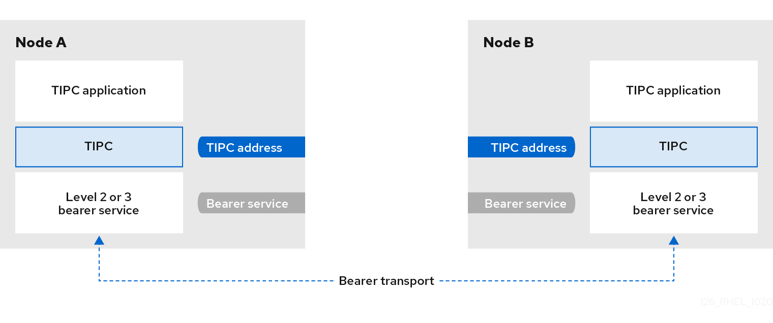
TIPC is a layer between applications using TIPC and a packet transport service (bearer), and spans the level of transport, network, and signaling link layers. However, TIPC can use a different transport protocol as bearer, so that, for example, a TCP connection can serve as a bearer for a TIPC signaling link.
TIPC supports the following bearers:
- Ethernet
- InfiniBand
- UDP protocol
TIPC provides a reliable transfer of messages between TIPC ports, that are the endpoints of all TIPC communication.
The following is a diagram of the TIPC architecture:
51.2. Loading the tipc module when the system boots
Before you can use the TIPC protocol, you must load the tipc kernel module. You can configure Red Hat Enterprise Linux to automatically load this kernel module automatically when the system boots.
Procedure
Create the
/etc/modules-load.d/tipc.conffile with the following content:tipcRestart the
systemd-modules-loadservice to load the module without rebooting the system:# systemctl start systemd-modules-load
Verification
Use the following command to verify that RHEL loaded the
tipcmodule:# lsmod | grep tipc tipc 311296 0If the command shows no entry for the
tipcmodule, RHEL failed to load it.
51.3. Creating a TIPC network
To create a TIPC network, perform this procedure on each host that should join the TIPC network.
The commands configure the TIPC network only temporarily. To permanently configure TIPC on a node, use the commands of this procedure in a script, and configure RHEL to execute that script when the system boots.
Prerequisites
-
The
tipcmodule has been loaded. For details, see Loading the tipc module when the system boots
Procedure
Optional: Set a unique node identity, such as a UUID or the node’s host name:
# tipc node set identity host_nameThe identity can be any unique string consisting of a maximum 16 letters and numbers.
You cannot set or change an identity after this step.
Add a bearer. For example, to use Ethernet as media and
enp0s1device as physical bearer device, enter:# tipc bearer enable media eth device enp1s0- Optional: For redundancy and better performance, attach further bearers using the command from the previous step. You can configure up to three bearers, but not more than two on the same media.
- Repeat all previous steps on each node that should join the TIPC network.
Verification
Display the link status for cluster members:
# tipc link list
broadcast-link: up
5254006b74be:enp1s0-525400df55d1:enp1s0: up
This output indicates that the link between bearer
enp1s0on node5254006b74beand bearerenp1s0on node525400df55d1isup.Display the TIPC publishing table:
# tipc nametable show Type Lower Upper Scope Port Node 0 1795222054 1795222054 cluster 0 5254006b74be 0 3741353223 3741353223 cluster 0 525400df55d1 1 1 1 node 2399405586 5254006b74be 2 3741353223 3741353223 node 0 5254006b74be-
The two entries with service type
0indicate that two nodes are members of this cluster. -
The entry with service type
1represents the built-in topology service tracking service. -
The entry with service type
2displays the link as seen from the issuing node. The range limit3741353223represents the peer endpoint’s address (a unique 32-bit hash value based on the node identity) in decimal format.
-
The two entries with service type