此内容没有您所选择的语言版本。
3.3. APC Fence Device Configuration Procedure
This section provides the procedure for adding an APC fence device to each node of cluster
apcclust. This example uses the same APC switch for each cluster node. The APC fence device will first be configured as a shared fence device. After configuring the APC switch as a shared fence device, the device will be added as a fence device for each node in the cluster.
To configure an APC switch as a shared fence device using Conga, perform the following procedure:
- As an administrator of luci Select the cluster tab. This displays the Choose a cluster to administer screen.
- From the Choose a cluster to administer screen, you should see the previously configured cluster
apcclustdisplayed, along with the nodes that make up the cluster. Click onapcclustto select the cluster. - At the detailed menu for the cluster
apcclust(below the menu on the left side of the screen), click . Clicking causes the display of any shared fence devices previously configured for a cluster and causes the display of menu items for fence device configuration: and . - Click . Clicking causes the Add a Sharable Fence Device page to be displayed.
- At the Add a Sharable Fence Device page, click the drop-down box under and select . This causes Conga to display the components of an APC Power Switch fencing type, as shown in Figure 3.2, “Adding a Sharable Fence Device”.
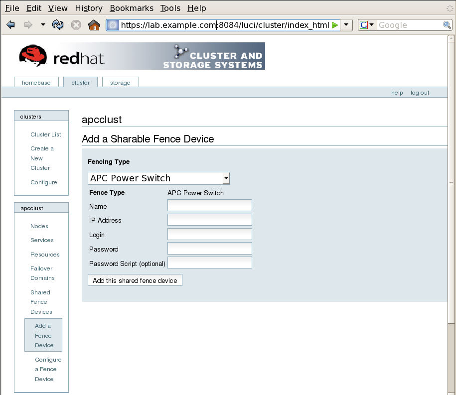
Figure 3.2. Adding a Sharable Fence Device
- For , enter
apcfence. - For , enter
10.15.86.96. - For , enter
apclogin. - For , enter
apcpword. - For , leave blank.
- Click .Clicking causes a progress page to be displayed temporarily. After the fence device has been added, the detailed cluster properties menu is updated with the fence device under .
After configuring the APC switch as a shared fence device, use the following procedure to configure the APC switch as the fence device for node
clusternode1.example.com
- At the detailed menu for the cluster
apcclust(below the menu), click . Clicking causes the display of the status of each node inapcclust. - At the bottom of the display for node
clusternode1.example.com, click . This displays the configuration screen for nodeclusternode1.example.com. - At the
Main Fencing Methoddisplay, click . This causes a dropdown menu to display. - From the dropdown menu, the fence device you have already created should display as one of the menu options under . Select . This causes a fence device configuration menu to display with the , , , , and values already configured, as defined when you configured
apcfenceas a shared fence device. This is shown in Figure 3.3, “Adding an Existing Fence Device to a Node”.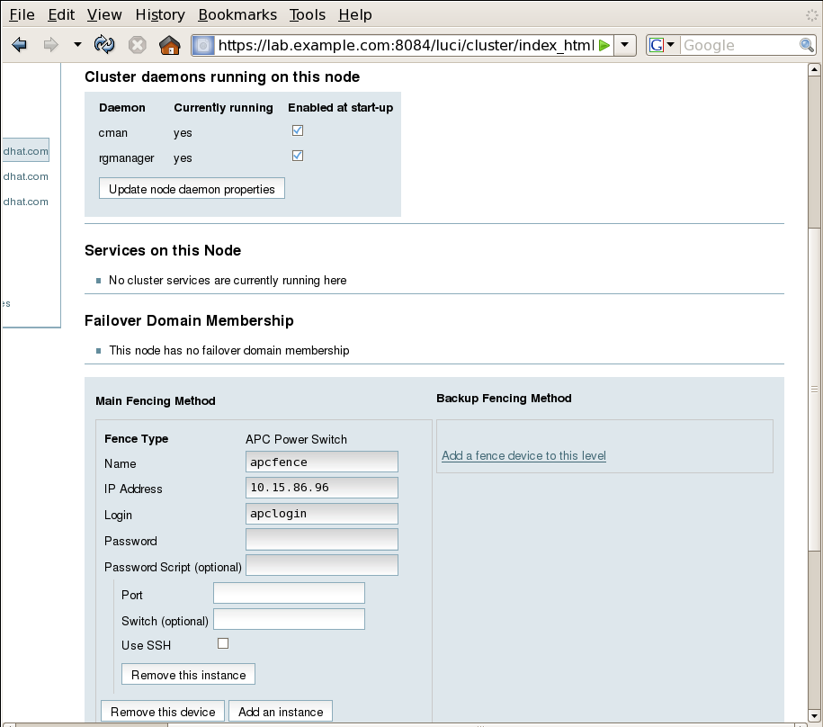
Figure 3.3. Adding an Existing Fence Device to a Node
- For , enter
1. Do not enter any value for . - Click . This causes a confirmation screen to be displayed.
- On the confirmation screen, Click . A progress page is displayed after which the display returns to the status page for
clusternode1.example.comin clusterapcclust.
After configuring
apcfence as the fencing device for clusternode1.example.com, use the same procedure to configure apcfence as the fencing device for clusternode2.example.com, specifying Port 2 for clusternode2.example.com, as in the following procedure:
- On the status page for
clusternode1.example.comin clusterapcclust, the other nodes inapcclustare displayed below the menu item below the menu item on the left side of the screen. Click to display the status screen for . - At the
Main Fencing Methoddisplay, click . This causes a dropdown manu to display. - As for
clusternode1.example.com, the fence device should display as one of the menu options on the dropdown menu, under . Select . This causes a fence device configuration menu to display with the , , , , values already configured, as defined when you configuredapcfenceas a shared fence device. - For , enter
2. Do not enter any value for . - Click .
Similarly, configure
apcfence as the main fencing method for clusternode3.example.com, specifying 3 as the Port number.