此内容没有您所选择的语言版本。
Chapter 6. Configuring Fencing with Dual Power Supplies
If your system is configured with redundant power supplies for your system, you must be sure to configure fencing so that your nodes fully shut down when they need to be fenced. If you configure each power supply as a separate fence method, each power supply will be fenced separately; the second power supply will allow the system to continue running when the first power supply is fenced and the system will not be fenced at all. To configure a system with dual power supplies, you must configure your fence devices so that both power supplies are shut off and the system is taken completely down. This requires that you configure two fencing devices inside of a single fencing method.
This chapter provides the procedures for using the Conga configuration tool in a Red Hat cluster to configure fencing with dual power supplies.
Figure 6.1, “Fence Devices with Dual Power Supplies” shows the configuration this procedure yields. In this configuration, there are two APC network power switches, each of which runs on its own separate UPS and has its own unique IP address. Each node in the cluster is connected to a port on each APC switch.
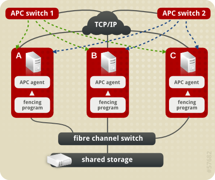
Figure 6.1. Fence Devices with Dual Power Supplies
6.1. Dual Power Fencing Prerequisite Configuration
复制链接链接已复制到粘贴板!
Table 6.1, “Configuration Prerequisities” summarizes the prerequisite components that have been set up before this procedure begins.
| Component | Name | Comment |
|---|---|---|
| cluster | apcclust | three-node cluster |
| cluster node | clusternode1.example.com | node in cluster apcclust configured with 2 APC switches to administer power supply |
| cluster node | clusternode2.example.com | node in cluster apcclust configured with 2 APC switches to administer power supply |
| cluster node | clusternode3.example.com | node in cluster apcclust configured with 2 APC switches to administer power supply |
| IP address | 10.15.86.96 | IP address for the first APC switch that controls the power for for clusternode1.example.com, clusternode2.example.com, and clusternode3.example.com. This switch runs on its own UPS. |
| IP address | 10.15.86.97 | IP address for the second APC switch that controls the power for for clusternode1.example.com, clusternode2.example.com, and clusternode3.example.com. This switch runs on its own UPS. |
Table 6.2, “Configuration Prerequisities” summarizes the prerequisite components that have been set up for each of the APC switches before this procedure begins.
| Component | Name | Comment |
|---|---|---|
| login | apclogin | login value for both of the the APC switches that control the power for for clusternode1.example.com, clusternode2.example.com, and clusternode3.example.com |
| password | apcpword | password for both the APC switches that control the power for for clusternode1.example.com, clusternode2.example.com, and clusternode3.example.com |
| port | 1 | port number on both of the APC switches that clusternode1.example.com connects to |
| port | 2 | port number on both of the APC switches that clusternode2.example.com connects to |
| port | 3 | port number on both of the APC switches that clusternode3.example.com connects to |