Postinstallation configuration
Day 2 operations for OpenShift Container Platform
Abstract
Chapter 1. Postinstallation configuration overview
After installing OpenShift Container Platform, a cluster administrator can configure and customize the following components:
- Machine
- Bare metal
- Cluster
- Node
- Network
- Storage
- Users
- Alerts and notifications
1.1. Postinstallation configuration tasks
You can perform the postinstallation configuration tasks to configure your environment to meet your needs.
The following lists details these configurations:
-
Configure operating system features: The Machine Config Operator (MCO) manages
MachineConfigobjects. By using the MCO, you can configure nodes and custom resources. Configure bare metal nodes: You can use the Bare Metal Operator (BMO) to manage bare metal hosts. The BMO can complete the following operations:
- Inspects hardware details of the host and report them to the bare metal host.
- Inspect firmware and configure BIOS settings.
- Provision hosts with a desired image.
- Clean disk contents for the host before or after provisioning the host.
Configure cluster features. You can modify the following features of an OpenShift Container Platform cluster:
- Image registry
- Networking configuration
- Image build behavior
- Identity provider
- The etcd configuration
- Machine set creation to handle the workloads
- Cloud provider credential management
Configuring a private cluster: By default, the installation program provisions OpenShift Container Platform by using a publicly accessible DNS and endpoints. To make your cluster accessible only from within an internal network, configure the following components to make them private:
- DNS
- Ingress Controller
- API server
Perform node operations: By default, OpenShift Container Platform uses Red Hat Enterprise Linux CoreOS (RHCOS) compute machines. You can perform the following node operations:
- Add and remove compute machines.
- Add and remove taints and tolerations.
- Configure the maximum number of pods per node.
- Enable Device Manager.
Configure users: Users can authenticate themselves to the API by using OAuth access tokens. You can configure OAuth to perform the following tasks:
- Specify an identity provider.
- Use role-based access control to define and grant permissions to users.
- Install an Operator from OperatorHub.
- Configuring alert notifications: By default, firing alerts are displayed on the Alerting UI of the web console. You can also configure OpenShift Container Platform to send alert notifications to external systems.
Chapter 2. Configuring a private cluster
After you install an OpenShift Container Platform version 4.16 cluster, you can set some of its core components to be private.
2.1. About private clusters
By default, OpenShift Container Platform is provisioned using publicly-accessible DNS and endpoints. You can set the DNS, Ingress Controller, and API server to private after you deploy your private cluster.
If the cluster has any public subnets, load balancer services created by administrators might be publicly accessible. To ensure cluster security, verify that these services are explicitly annotated as private.
2.1.1. DNS
If you install OpenShift Container Platform on installer-provisioned infrastructure, the installation program creates records in a pre-existing public zone and, where possible, creates a private zone for the cluster’s own DNS resolution. In both the public zone and the private zone, the installation program or cluster creates DNS entries for *.apps, for the Ingress object, and api, for the API server.
The *.apps records in the public and private zone are identical, so when you delete the public zone, the private zone seamlessly provides all DNS resolution for the cluster.
2.1.2. Ingress Controller
Because the default Ingress object is created as public, the load balancer is internet-facing and in the public subnets.
The Ingress Operator generates a default certificate for an Ingress Controller to serve as a placeholder until you configure a custom default certificate. Do not use Operator-generated default certificates in production clusters. The Ingress Operator does not rotate its own signing certificate or the default certificates that it generates. Operator-generated default certificates are intended as placeholders for custom default certificates that you configure.
2.1.3. API server
By default, the installation program creates appropriate network load balancers for the API server to use for both internal and external traffic.
On Amazon Web Services (AWS), separate public and private load balancers are created. The load balancers are identical except that an additional port is available on the internal one for use within the cluster. Although the installation program automatically creates or destroys the load balancer based on API server requirements, the cluster does not manage or maintain them. As long as you preserve the cluster’s access to the API server, you can manually modify or move the load balancers. For the public load balancer, port 6443 is open and the health check is configured for HTTPS against the /readyz path.
On Google Cloud, a single load balancer is created to manage both internal and external API traffic, so you do not need to modify the load balancer.
On Microsoft Azure, both public and private load balancers are created. However, because of limitations in current implementation, you just retain both load balancers in a private cluster.
2.2. Configuring DNS records to be published in a private zone
For all OpenShift Container Platform clusters, whether public or private, DNS records are published in a public zone by default.
You can remove the public zone from the cluster DNS configuration to avoid exposing DNS records to the public. You might want to avoid exposing sensitive information, such as internal domain names, internal IP addresses, or the number of clusters at an organization, or you might simply have no need to publish records publicly. If all the clients that should be able to connect to services within the cluster use a private DNS service that has the DNS records from the private zone, then there is no need to have a public DNS record for the cluster.
After you deploy a cluster, you can modify its DNS to use only a private zone by modifying the DNS custom resource (CR). Modifying the DNS CR in this way means that any DNS records that are subsequently created are not published to public DNS servers, which keeps knowledge of the DNS records isolated to internal users. This can be done when you configure the cluster to be private, or if you never want DNS records to be publicly resolvable.
Alternatively, even in a private cluster, you might keep the public zone for DNS records because it allows clients to resolve DNS names for applications running on that cluster. For example, an organization can have machines that connect to the public internet and then establish VPN connections for certain private IP ranges in order to connect to private IP addresses. The DNS lookups from these machines use the public DNS to determine the private addresses of those services, and then connect to the private addresses over the VPN.
Procedure
Review the
DNSCR for your cluster by running the following command and observing the output:$ oc get dnses.config.openshift.io/cluster -o yamlExample output
apiVersion: config.openshift.io/v1 kind: DNS metadata: creationTimestamp: "2019-10-25T18:27:09Z" generation: 2 name: cluster resourceVersion: "37966" selfLink: /apis/config.openshift.io/v1/dnses/cluster uid: 0e714746-f755-11f9-9cb1-02ff55d8f976 spec: baseDomain: <base_domain> privateZone: tags: Name: <infrastructure_id>-int kubernetes.io/cluster/<infrastructure_id>: owned publicZone: id: Z2XXXXXXXXXXA4 status: {}Note that the
specsection contains both a private and a public zone.Patch the
DNSCR to remove the public zone by running the following command:$ oc patch dnses.config.openshift.io/cluster --type=merge --patch='{"spec": {"publicZone": null}}'Example output
dns.config.openshift.io/cluster patchedThe Ingress Operator consults the
DNSCR definition when it creates DNS records forIngressControllerobjects. If only private zones are specified, only private records are created.ImportantExisting DNS records are not modified when you remove the public zone. You must manually delete previously published public DNS records if you no longer want them to be published publicly.
Verification
Review the
DNSCR for your cluster and confirm that the public zone was removed, by running the following command and observing the output:$ oc get dnses.config.openshift.io/cluster -o yamlExample output
apiVersion: config.openshift.io/v1 kind: DNS metadata: creationTimestamp: "2019-10-25T18:27:09Z" generation: 2 name: cluster resourceVersion: "37966" selfLink: /apis/config.openshift.io/v1/dnses/cluster uid: 0e714746-f755-11f9-9cb1-02ff55d8f976 spec: baseDomain: <base_domain> privateZone: tags: Name: <infrastructure_id>-int kubernetes.io/cluster/<infrastructure_id>-wfpg4: owned status: {}
2.3. Setting the Ingress Controller to private
After you deploy a cluster, you can modify its Ingress Controller to use only a private zone.
Procedure
Modify the default Ingress Controller to use only an internal endpoint:
$ oc replace --force --wait --filename - <<EOF apiVersion: operator.openshift.io/v1 kind: IngressController metadata: namespace: openshift-ingress-operator name: default spec: endpointPublishingStrategy: type: LoadBalancerService loadBalancer: scope: Internal EOFExample output
ingresscontroller.operator.openshift.io "default" deleted ingresscontroller.operator.openshift.io/default replacedThe public DNS entry is removed, and the private zone entry is updated.
2.4. Restricting the API server to private for an Amazon Web Services cluster
If the security posture of your organization does not allow clusters to use an open API endpoint, you can restrict the API server to use only internal load balancers. To implement this API server restriction, use the Amazon Web Services (AWS) console and OpenShift CLI (oc) to delete the external load balancer components.
The OpenShift CLI (oc) steps that remove the external load balancers require the Machine API. For clusters that cannot use the Machine API, you must manually remove the external load balancers.
Clusters with the infrastructure platform type none cannot use the Machine API. To view the platform type for your cluster, run the following command:
$ oc get infrastructure cluster -o jsonpath='{.status.platform}'Prerequisites
- You have installed an OpenShift Container Platform cluster on AWS.
- You have access to the AWS console as a user with administrator privileges.
-
You have access to the OpenShift CLI (
oc) as a user with administrator privileges.
Procedure
- Log in to the AWS console as a user with administrator privileges.
Delete the external load balancer.
NoteThe API DNS entry in the private zone already points to the internal load balancer, which uses an identical configuration, so you do not need to modify the internal load balancer.
Delete the
api.<cluster_name>.<domain_name>DNS entry in the public zone.where
<cluster_name>is the name of the cluster and<domain_name>is the base domain for the cluster.To remove the external load balancers, log in to the OpenShift CLI (
oc) as a user with administrator privileges.If your cluster uses a control plane machine set, remove the external load balancers by editing the
ControlPlaneMachineSetcustom resource (CR).Edit the
ControlPlaneMachineSetCR by running the following command:$ oc edit controlplanemachineset.machine.openshift.io cluster \ -n openshift-machine-apiRemove the external load balancers by deleting the corresponding lines in the control plane machine set custom resource (CR).
In the
spec.template.spec.providerSpec.value.loadBalancerssection of the CR, thenamevalue for the external load balancer ends in-ext. Delete the line with the external load balancernamevalue and the line with the external load balancertypevalue that accompanies it.apiVersion: machine.openshift.io/v1 kind: ControlPlaneMachineSet metadata: name: cluster namespace: openshift-machine-api spec: # ... template: # ... spec: providerSpec: value: loadBalancers: - name: <cluster_id>-ext type: network - name: <cluster_id>-int type: network # ...Save your changes and exit the object specification.
When you save an update to the control plane machine set, the Control Plane Machine Set Operator updates the control plane machines according to your configured update strategy. For more information, see "Updating the control plane configuration".
If your cluster does not use a control plane machine set, you must delete the external load balancers from each control plane machine.
List the cluster machines by running the following command:
$ oc get machine -n openshift-machine-apiExample output
NAME STATE TYPE REGION ZONE AGE <cluster_id>-master-0 running m4.xlarge us-east-1 us-east-1a 17m <cluster_id>-master-1 running m4.xlarge us-east-1 us-east-1b 17m <cluster_id>-master-2 running m4.xlarge us-east-1 us-east-1a 17m <cluster_id>-worker-us-east-1a-<zone_tag> running m4.xlarge us-east-1 us-east-1a 15m <cluster_id>-worker-us-east-1a-<zone_tag> running m4.xlarge us-east-1 us-east-1a 15m <cluster_id>-worker-us-east-1b-<zone_tag> running m4.xlarge us-east-1 us-east-1b 15mThe control plane machines contain the
masterstring in their names.Remove the external load balancer from each control plane machine:
Edit a control plane machine object to by running the following command:
$ oc edit machines -n openshift-machine-api <control_plane_machine_name>where
<control_plane_machine_name>is the name of the control plane machine object to modify.Remove the lines that describe the external load balancer.
In the
spec.providerSpec.value.loadBalancerssection of the CR, thenamevalue for the external load balancer ends in-ext. Delete the line with the external load balancernamevalue and the the line with the external load balancertypevalue that accompanies it.apiVersion: machine.openshift.io/v1beta1 kind: Machine metadata: name: <control_plane_machine_name> namespace: openshift-machine-api spec: providerSpec: value: loadBalancers: - name: <cluster_id>-ext type: network - name: <cluster_id>-int type: network # ...- Save your changes and exit the object specification.
- Repeat this process for each control plane machine.
2.5. Restricting the API server to private for an Microsoft Azure cluster
If the security posture of your organization does not allow clusters to use an open API endpoint, you can restrict the API server to use only internal load balancers. To implement this API server restriction, use the Microsoft Azure console to delete the external load balancer component.
Prerequisites
- You have installed an OpenShift Container Platform cluster on Azure.
- You have access to the Azure console as a user with administrator privileges.
Procedure
- Log in to the Azure console as a user with administrator privileges.
Delete the following resources:
-
The
api-v4rule for the public load balancer. -
The
frontendIPConfigurationparameter that is associated with theapi-v4rule for the public load balancer. -
The public IP address that is specified in the
frontendIPConfigurationparameter.
-
The
-
Configure the Ingress Controller endpoint publishing scope to
Internal. For more information, see "Configuring the Ingress Controller endpoint publishing scope to Internal". Delete the
api.<cluster_name>DNS entry in the public zone.where
<cluster_name>is the name of the cluster.
2.6. Configuring a private storage endpoint on Azure
You can leverage the Image Registry Operator to use private endpoints on Azure, which enables seamless configuration of private storage accounts when OpenShift Container Platform is deployed on private Azure clusters. This allows you to deploy the image registry without exposing public-facing storage endpoints.
Do not configure a private storage endpoint on Microsoft Azure Red Hat OpenShift (ARO), because the endpoint can put your Microsoft Azure Red Hat OpenShift cluster in an unrecoverable state.
You can configure the Image Registry Operator to use private storage endpoints on Azure in one of two ways:
- By configuring the Image Registry Operator to discover the VNet and subnet names
- With user-provided Azure Virtual Network (VNet) and subnet names
2.6.1. Limitations for configuring a private storage endpoint on Azure
The following limitations apply when configuring a private storage endpoint on Azure:
-
When configuring the Image Registry Operator to use a private storage endpoint, public network access to the storage account is disabled. Consequently, pulling images from the registry outside of OpenShift Container Platform only works by setting
disableRedirect: truein the registry Operator configuration. With redirect enabled, the registry redirects the client to pull images directly from the storage account, which will no longer work due to disabled public network access. For more information, see "Disabling redirect when using a private storage endpoint on Azure". - This operation cannot be undone by the Image Registry Operator.
2.6.2. Configuring a private storage endpoint on Azure by enabling the Image Registry Operator to discover VNet and subnet names
The following procedure shows you how to set up a private storage endpoint on Azure by configuring the Image Registry Operator to discover VNet and subnet names.
Prerequisites
- You have configured the image registry to run on Azure.
Your network has been set up using the Installer Provisioned Infrastructure installation method.
For users with a custom network setup, see "Configuring a private storage endpoint on Azure with user-provided VNet and subnet names".
Procedure
Edit the Image Registry Operator
configobject and setnetworkAccess.typetoInternal:$ oc edit configs.imageregistry/cluster# ... spec: # ... storage: azure: # ... networkAccess: type: Internal # ...Optional: Enter the following command to confirm that the Operator has completed provisioning. This might take a few minutes.
$ oc get configs.imageregistry/cluster -o=jsonpath="{.spec.storage.azure.privateEndpointName}" -wOptional: If the registry is exposed by a route, and you are configuring your storage account to be private, you must disable redirect if you want pulls external to the cluster to continue to work. Enter the following command to disable redirect on the Image Operator configuration:
$ oc patch configs.imageregistry cluster --type=merge -p '{"spec":{"disableRedirect": true}}'NoteWhen redirect is enabled, pulling images from outside of the cluster will not work.
Verification
Fetch the registry service name by running the following command:
$ oc registry info --internal=trueExample output
image-registry.openshift-image-registry.svc:5000Enter debug mode by running the following command:
$ oc debug node/<node_name>Run the suggested
chrootcommand. For example:$ chroot /hostEnter the following command to log in to your container registry:
$ podman login --tls-verify=false -u unused -p $(oc whoami -t) image-registry.openshift-image-registry.svc:5000Example output
Login Succeeded!Enter the following command to verify that you can pull an image from the registry:
$ podman pull --tls-verify=false image-registry.openshift-image-registry.svc:5000/openshift/toolsExample output
Trying to pull image-registry.openshift-image-registry.svc:5000/openshift/tools/openshift/tools... Getting image source signatures Copying blob 6b245f040973 done Copying config 22667f5368 done Writing manifest to image destination Storing signatures 22667f53682a2920948d19c7133ab1c9c3f745805c14125859d20cede07f11f9
2.6.3. Configuring a private storage endpoint on Azure with user-provided VNet and subnet names
Use the following procedure to configure a storage account that has public network access disabled and is exposed behind a private storage endpoint on Azure.
Prerequisites
- You have configured the image registry to run on Azure.
- You must know the VNet and subnet names used for your Azure environment.
- If your network was configured in a separate resource group in Azure, you must also know its name.
Procedure
Edit the Image Registry Operator
configobject and configure the private endpoint using your VNet and subnet names:$ oc edit configs.imageregistry/cluster# ... spec: # ... storage: azure: # ... networkAccess: type: Internal internal: subnetName: <subnet_name> vnetName: <vnet_name> networkResourceGroupName: <network_resource_group_name> # ...Optional: Enter the following command to confirm that the Operator has completed provisioning. This might take a few minutes.
$ oc get configs.imageregistry/cluster -o=jsonpath="{.spec.storage.azure.privateEndpointName}" -wNoteWhen redirect is enabled, pulling images from outside of the cluster will not work.
Verification
Fetch the registry service name by running the following command:
$ oc registry info --internal=trueExample output
image-registry.openshift-image-registry.svc:5000Enter debug mode by running the following command:
$ oc debug node/<node_name>Run the suggested
chrootcommand. For example:$ chroot /hostEnter the following command to log in to your container registry:
$ podman login --tls-verify=false -u unused -p $(oc whoami -t) image-registry.openshift-image-registry.svc:5000Example output
Login Succeeded!Enter the following command to verify that you can pull an image from the registry:
$ podman pull --tls-verify=false image-registry.openshift-image-registry.svc:5000/openshift/toolsExample output
Trying to pull image-registry.openshift-image-registry.svc:5000/openshift/tools/openshift/tools... Getting image source signatures Copying blob 6b245f040973 done Copying config 22667f5368 done Writing manifest to image destination Storing signatures 22667f53682a2920948d19c7133ab1c9c3f745805c14125859d20cede07f11f9
2.6.4. Optional: Disabling redirect when using a private storage endpoint on Azure
By default, redirect is enabled when using the image registry. Redirect allows off-loading of traffic from the registry pods into the object storage, which makes pull faster. When redirect is enabled and the storage account is private, users from outside of the cluster are unable to pull images from the registry.
In some cases, users might want to disable redirect so that users from outside of the cluster can pull images from the registry.
Use the following procedure to disable redirect.
Prerequisites
- You have configured the image registry to run on Azure.
- You have configured a route.
Procedure
Enter the following command to disable redirect on the image registry configuration:
$ oc patch configs.imageregistry cluster --type=merge -p '{"spec":{"disableRedirect": true}}'
Verification
Fetch the registry service name by running the following command:
$ oc registry infoExample output
default-route-openshift-image-registry.<cluster_dns>Enter the following command to log in to your container registry:
$ podman login --tls-verify=false -u unused -p $(oc whoami -t) default-route-openshift-image-registry.<cluster_dns>Example output
Login Succeeded!Enter the following command to verify that you can pull an image from the registry:
$ podman pull --tls-verify=false default-route-openshift-image-registry.<cluster_dns> /openshift/toolsExample output
Trying to pull default-route-openshift-image-registry.<cluster_dns>/openshift/tools... Getting image source signatures Copying blob 6b245f040973 done Copying config 22667f5368 done Writing manifest to image destination Storing signatures 22667f53682a2920948d19c7133ab1c9c3f745805c14125859d20cede07f11f9
Chapter 3. Bare-metal configuration
When deploying OpenShift Container Platform on bare-metal hosts, there are times when you need to make changes to the host either before or after provisioning. This can include inspecting the host’s hardware, firmware, and firmware details. It can also include formatting disks or changing modifiable firmware settings.
3.1. Services for a user-managed load balancer
To integrate your infrastructure with existing network standards or gain more control over traffic management in OpenShift Container Platform , configure services for a user-managed load balancer.
Configuring a user-managed load balancer depends on your vendor’s load balancer.
The information and examples in this section are for guideline purposes only. Consult the vendor documentation for more specific information about the vendor’s load balancer.
Red Hat supports the following services for a user-managed load balancer:
- Ingress Controller
- OpenShift API
- OpenShift MachineConfig API
You can choose whether you want to configure one or all of these services for a user-managed load balancer. Configuring only the Ingress Controller service is a common configuration option. To better understand each service, view the following diagrams:
Figure 3.1. Example network workflow that shows an Ingress Controller operating in an OpenShift Container Platform environment
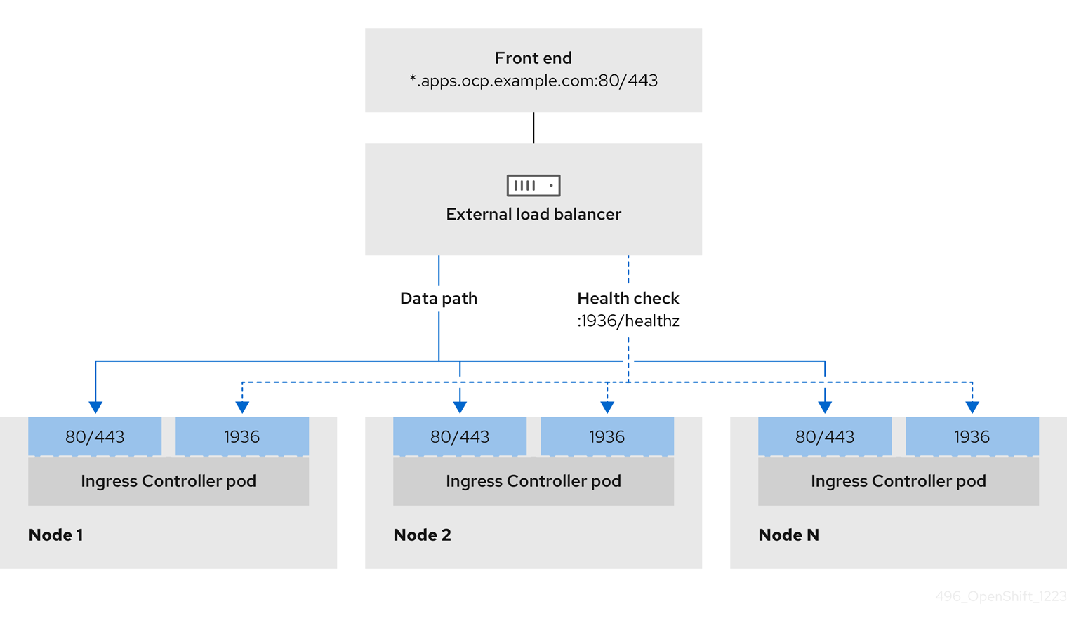
Figure 3.2. Example network workflow that shows an OpenShift API operating in an OpenShift Container Platform environment

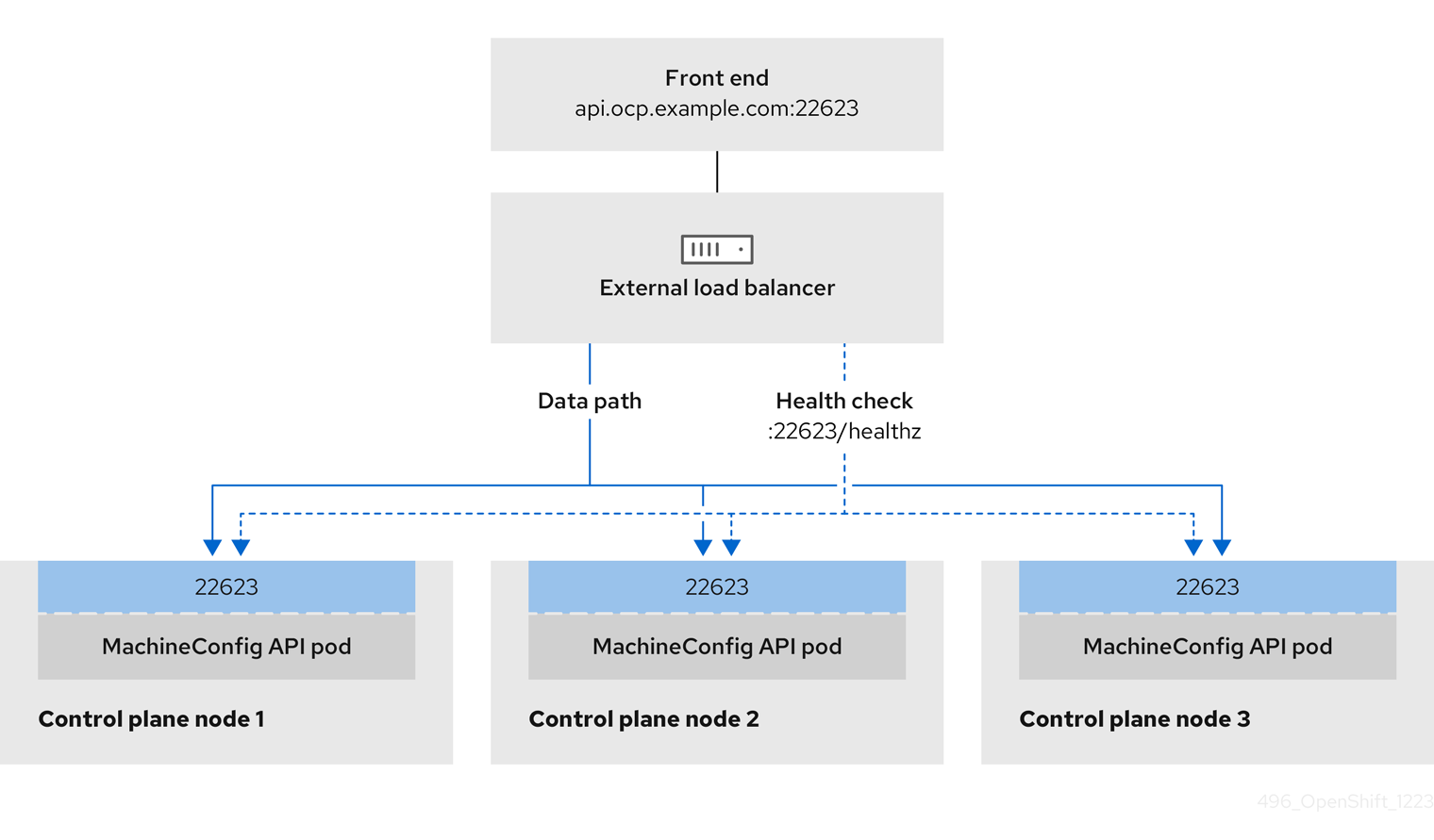
Figure 3.3. Example network workflow that shows an OpenShift MachineConfig API operating in an OpenShift Container Platform environment
The following configuration options are supported for user-managed load balancers:
- Use a node selector to map the Ingress Controller to a specific set of nodes. You must assign a static IP address to each node in this set, or configure each node to receive the same IP address from the Dynamic Host Configuration Protocol (DHCP). Infrastructure nodes commonly receive this type of configuration.
Target all IP addresses on a subnet. This configuration can reduce maintenance overhead, because you can create and destroy nodes within those networks without reconfiguring the load balancer targets. If you deploy your ingress pods by using a machine set on a smaller network, such as a
/27or/28, you can simplify your load balancer targets.TipYou can list all IP addresses that exist in a network by checking the machine config pool’s resources.
Before you configure a user-managed load balancer for your OpenShift Container Platform cluster, consider the following information:
- For a front-end IP address, you can use the same IP address for the front-end IP address, the Ingress Controller’s load balancer, and API load balancer. Check the vendor’s documentation for this capability.
For a back-end IP address, ensure that an IP address for an OpenShift Container Platform control plane node does not change during the lifetime of the user-managed load balancer. You can achieve this by completing one of the following actions:
- Assign a static IP address to each control plane node.
- Configure each node to receive the same IP address from the DHCP every time the node requests a DHCP lease. Depending on the vendor, the DHCP lease might be in the form of an IP reservation or a static DHCP assignment.
- Manually define each node that runs the Ingress Controller in the user-managed load balancer for the Ingress Controller back-end service. For example, if the Ingress Controller moves to an undefined node, a connection outage can occur.
3.1.1. Configuring a user-managed load balancer
To integrate your infrastructure with existing network standards or gain more control over traffic management in OpenShift Container Platform , use a user-managed load balancer in place of the default load balancer.
Before you configure a user-managed load balancer, ensure that you read the "Services for a user-managed load balancer" section.
Read the following prerequisites that apply to the service that you want to configure for your user-managed load balancer.
MetalLB, which runs on a cluster, functions as a user-managed load balancer.
Prerequisites
The following list details OpenShift API prerequisites:
- You defined a front-end IP address.
TCP ports 6443 and 22623 are exposed on the front-end IP address of your load balancer. Check the following items:
- Port 6443 provides access to the OpenShift API service.
- Port 22623 can provide ignition startup configurations to nodes.
- The front-end IP address and port 6443 are reachable by all users of your system with a location external to your OpenShift Container Platform cluster.
- The front-end IP address and port 22623 are reachable only by OpenShift Container Platform nodes.
- The load balancer backend can communicate with OpenShift Container Platform control plane nodes on port 6443 and 22623.
The following list details Ingress Controller prerequisites:
- You defined a front-end IP address.
- TCP port 443 and port 80 are exposed on the front-end IP address of your load balancer.
- The front-end IP address, port 80 and port 443 are reachable by all users of your system with a location external to your OpenShift Container Platform cluster.
- The front-end IP address, port 80 and port 443 are reachable by all nodes that operate in your OpenShift Container Platform cluster.
- The load balancer backend can communicate with OpenShift Container Platform nodes that run the Ingress Controller on ports 80, 443, and 1936.
The following list details prerequisites for health check URL specifications:
You can configure most load balancers by setting health check URLs that determine if a service is available or unavailable. OpenShift Container Platform provides these health checks for the OpenShift API, Machine Configuration API, and Ingress Controller backend services.
The following example shows a Kubernetes API health check specification for a backend service:
Path: HTTPS:6443/readyz
Healthy threshold: 2
Unhealthy threshold: 2
Timeout: 10
Interval: 10The following example shows a Machine Config API health check specification for a backend service:
Path: HTTPS:22623/healthz
Healthy threshold: 2
Unhealthy threshold: 2
Timeout: 10
Interval: 10The following example shows a Ingress Controller health check specification for a backend service:
Path: HTTP:1936/healthz/ready
Healthy threshold: 2
Unhealthy threshold: 2
Timeout: 5
Interval: 10Procedure
Configure the HAProxy Ingress Controller, so that you can enable access to the cluster from your load balancer on ports 6443, 22623, 443, and 80. Depending on your needs, you can specify the IP address of a single subnet or IP addresses from multiple subnets in your HAProxy configuration.
Example HAProxy configuration with one listed subnet
# ... listen my-cluster-api-6443 bind 192.168.1.100:6443 mode tcp balance roundrobin option httpchk http-check connect http-check send meth GET uri /readyz http-check expect status 200 server my-cluster-master-2 192.168.1.101:6443 check inter 10s rise 2 fall 2 server my-cluster-master-0 192.168.1.102:6443 check inter 10s rise 2 fall 2 server my-cluster-master-1 192.168.1.103:6443 check inter 10s rise 2 fall 2 listen my-cluster-machine-config-api-22623 bind 192.168.1.100:22623 mode tcp balance roundrobin option httpchk http-check connect http-check send meth GET uri /healthz http-check expect status 200 server my-cluster-master-2 192.168.1.101:22623 check inter 10s rise 2 fall 2 server my-cluster-master-0 192.168.1.102:22623 check inter 10s rise 2 fall 2 server my-cluster-master-1 192.168.1.103:22623 check inter 10s rise 2 fall 2 listen my-cluster-apps-443 bind 192.168.1.100:443 mode tcp balance roundrobin option httpchk http-check connect http-check send meth GET uri /healthz/ready http-check expect status 200 server my-cluster-worker-0 192.168.1.111:443 check port 1936 inter 10s rise 2 fall 2 server my-cluster-worker-1 192.168.1.112:443 check port 1936 inter 10s rise 2 fall 2 server my-cluster-worker-2 192.168.1.113:443 check port 1936 inter 10s rise 2 fall 2 listen my-cluster-apps-80 bind 192.168.1.100:80 mode tcp balance roundrobin option httpchk http-check connect http-check send meth GET uri /healthz/ready http-check expect status 200 server my-cluster-worker-0 192.168.1.111:80 check port 1936 inter 10s rise 2 fall 2 server my-cluster-worker-1 192.168.1.112:80 check port 1936 inter 10s rise 2 fall 2 server my-cluster-worker-2 192.168.1.113:80 check port 1936 inter 10s rise 2 fall 2 # ...Example HAProxy configuration with multiple listed subnets
# ... listen api-server-6443 bind *:6443 mode tcp server master-00 192.168.83.89:6443 check inter 1s server master-01 192.168.84.90:6443 check inter 1s server master-02 192.168.85.99:6443 check inter 1s server bootstrap 192.168.80.89:6443 check inter 1s listen machine-config-server-22623 bind *:22623 mode tcp server master-00 192.168.83.89:22623 check inter 1s server master-01 192.168.84.90:22623 check inter 1s server master-02 192.168.85.99:22623 check inter 1s server bootstrap 192.168.80.89:22623 check inter 1s listen ingress-router-80 bind *:80 mode tcp balance source server worker-00 192.168.83.100:80 check inter 1s server worker-01 192.168.83.101:80 check inter 1s listen ingress-router-443 bind *:443 mode tcp balance source server worker-00 192.168.83.100:443 check inter 1s server worker-01 192.168.83.101:443 check inter 1s listen ironic-api-6385 bind *:6385 mode tcp balance source server master-00 192.168.83.89:6385 check inter 1s server master-01 192.168.84.90:6385 check inter 1s server master-02 192.168.85.99:6385 check inter 1s server bootstrap 192.168.80.89:6385 check inter 1s listen inspector-api-5050 bind *:5050 mode tcp balance source server master-00 192.168.83.89:5050 check inter 1s server master-01 192.168.84.90:5050 check inter 1s server master-02 192.168.85.99:5050 check inter 1s server bootstrap 192.168.80.89:5050 check inter 1s # ...Use the
curlCLI command to verify that the user-managed load balancer and its resources are operational:Verify that the cluster machine configuration API is accessible to the Kubernetes API server resource, by running the following command and observing the response:
$ curl https://<loadbalancer_ip_address>:6443/version --insecureIf the configuration is correct, you receive a JSON object in response:
{ "major": "1", "minor": "11+", "gitVersion": "v1.11.0+ad103ed", "gitCommit": "ad103ed", "gitTreeState": "clean", "buildDate": "2019-01-09T06:44:10Z", "goVersion": "go1.10.3", "compiler": "gc", "platform": "linux/amd64" }Verify that the cluster machine configuration API is accessible to the Machine config server resource, by running the following command and observing the output:
$ curl -v https://<loadbalancer_ip_address>:22623/healthz --insecureIf the configuration is correct, the output from the command shows the following response:
HTTP/1.1 200 OK Content-Length: 0Verify that the controller is accessible to the Ingress Controller resource on port 80, by running the following command and observing the output:
$ curl -I -L -H "Host: console-openshift-console.apps.<cluster_name>.<base_domain>" http://<load_balancer_front_end_IP_address>If the configuration is correct, the output from the command shows the following response:
HTTP/1.1 302 Found content-length: 0 location: https://console-openshift-console.apps.ocp4.private.opequon.net/ cache-control: no-cacheVerify that the controller is accessible to the Ingress Controller resource on port 443, by running the following command and observing the output:
$ curl -I -L --insecure --resolve console-openshift-console.apps.<cluster_name>.<base_domain>:443:<Load Balancer Front End IP Address> https://console-openshift-console.apps.<cluster_name>.<base_domain>If the configuration is correct, the output from the command shows the following response:
HTTP/1.1 200 OK referrer-policy: strict-origin-when-cross-origin set-cookie: csrf-token=UlYWOyQ62LWjw2h003xtYSKlh1a0Py2hhctw0WmV2YEdhJjFyQwWcGBsja261dGLgaYO0nxzVErhiXt6QepA7g==; Path=/; Secure; SameSite=Lax x-content-type-options: nosniff x-dns-prefetch-control: off x-frame-options: DENY x-xss-protection: 1; mode=block date: Wed, 04 Oct 2023 16:29:38 GMT content-type: text/html; charset=utf-8 set-cookie: 1e2670d92730b515ce3a1bb65da45062=1bf5e9573c9a2760c964ed1659cc1673; path=/; HttpOnly; Secure; SameSite=None cache-control: private
Configure the DNS records for your cluster to target the front-end IP addresses of the user-managed load balancer. You must update records to your DNS server for the cluster API and applications over the load balancer. The following examples shows modified DNS records:
<load_balancer_ip_address> A api.<cluster_name>.<base_domain> A record pointing to Load Balancer Front End<load_balancer_ip_address> A apps.<cluster_name>.<base_domain> A record pointing to Load Balancer Front EndImportantDNS propagation might take some time for each DNS record to become available. Ensure that each DNS record propagates before validating each record.
For your OpenShift Container Platform cluster to use the user-managed load balancer, you must specify the following configuration in your cluster’s
install-config.yamlfile:# ... platform: loadBalancer: type: UserManaged apiVIPs: - <api_ip>1 ingressVIPs: - <ingress_ip>2 # ...where:
loadBalancer.type-
Set
UserManagedfor thetypeparameter to specify a user-managed load balancer for your cluster. The parameter defaults toOpenShiftManagedDefault, which denotes the default internal load balancer. For services defined in anopenshift-kni-infranamespace, a user-managed load balancer can deploy thecorednsservice to pods in your cluster but ignoreskeepalivedandhaproxyservices. loadBalancer.<api_ip>- Specifies a user-managed load balancer. Specify the user-managed load balancer’s public IP address, so that the Kubernetes API can communicate with the user-managed load balancer. Mandatory parameter.
loadBalancer.<ingress_ip>- Specifies a user-managed load balancer. Specify the user-managed load balancer’s public IP address, so that the user-managed load balancer can manage ingress traffic for your cluster. Mandatory parameter.
Verification
Use the
curlCLI command to verify that the user-managed load balancer and DNS record configuration are operational:Verify that you can access the cluster API, by running the following command and observing the output:
$ curl https://api.<cluster_name>.<base_domain>:6443/version --insecureIf the configuration is correct, you receive a JSON object in response:
{ "major": "1", "minor": "11+", "gitVersion": "v1.11.0+ad103ed", "gitCommit": "ad103ed", "gitTreeState": "clean", "buildDate": "2019-01-09T06:44:10Z", "goVersion": "go1.10.3", "compiler": "gc", "platform": "linux/amd64" }Verify that you can access the cluster machine configuration, by running the following command and observing the output:
$ curl -v https://api.<cluster_name>.<base_domain>:22623/healthz --insecureIf the configuration is correct, the output from the command shows the following response:
HTTP/1.1 200 OK Content-Length: 0Verify that you can access each cluster application on port 80, by running the following command and observing the output:
$ curl http://console-openshift-console.apps.<cluster_name>.<base_domain> -I -L --insecureIf the configuration is correct, the output from the command shows the following response:
HTTP/1.1 302 Found content-length: 0 location: https://console-openshift-console.apps.<cluster-name>.<base domain>/ cache-control: no-cacheHTTP/1.1 200 OK referrer-policy: strict-origin-when-cross-origin set-cookie: csrf-token=39HoZgztDnzjJkq/JuLJMeoKNXlfiVv2YgZc09c3TBOBU4NI6kDXaJH1LdicNhN1UsQWzon4Dor9GWGfopaTEQ==; Path=/; Secure x-content-type-options: nosniff x-dns-prefetch-control: off x-frame-options: DENY x-xss-protection: 1; mode=block date: Tue, 17 Nov 2020 08:42:10 GMT content-type: text/html; charset=utf-8 set-cookie: 1e2670d92730b515ce3a1bb65da45062=9b714eb87e93cf34853e87a92d6894be; path=/; HttpOnly; Secure; SameSite=None cache-control: privateVerify that you can access each cluster application on port 443, by running the following command and observing the output:
$ curl https://console-openshift-console.apps.<cluster_name>.<base_domain> -I -L --insecureIf the configuration is correct, the output from the command shows the following response:
HTTP/1.1 200 OK referrer-policy: strict-origin-when-cross-origin set-cookie: csrf-token=UlYWOyQ62LWjw2h003xtYSKlh1a0Py2hhctw0WmV2YEdhJjFyQwWcGBsja261dGLgaYO0nxzVErhiXt6QepA7g==; Path=/; Secure; SameSite=Lax x-content-type-options: nosniff x-dns-prefetch-control: off x-frame-options: DENY x-xss-protection: 1; mode=block date: Wed, 04 Oct 2023 16:29:38 GMT content-type: text/html; charset=utf-8 set-cookie: 1e2670d92730b515ce3a1bb65da45062=1bf5e9573c9a2760c964ed1659cc1673; path=/; HttpOnly; Secure; SameSite=None cache-control: private
3.2. About the Bare Metal Operator
Use the Bare Metal Operator (BMO) to provision, manage, and inspect bare-metal hosts in your cluster.
The BMO uses the following resources to complete these tasks:
-
BareMetalHost -
HostFirmwareSettings -
FirmwareSchema -
HostFirmwareComponents
The BMO maintains an inventory of the physical hosts in the cluster by mapping each bare-metal host to an instance of the BareMetalHost custom resource definition. Each BareMetalHost resource features hardware, software, and firmware details. The BMO continually inspects the bare-metal hosts in the cluster to ensure each BareMetalHost resource accurately details the components of the corresponding host.
The BMO also uses the HostFirmwareSettings resource, the FirmwareSchema resource, and the HostFirmwareComponents resource to detail firmware specifications and upgrade or downgrade firmware for the bare-metal host.
The BMO interfaces with bare-metal hosts in the cluster by using the Ironic API service. The Ironic service uses the Baseboard Management Controller (BMC) on the host to interface with the machine.
Some common tasks you can complete by using the BMO include the following:
- Provision bare-metal hosts to the cluster with a specific image
- Format a host’s disk contents before provisioning or after deprovisioning
- Turn on or off a host
- Change firmware settings
- View the host’s hardware details
- Upgrade or downgrade a host’s firmware to a specific version
3.2.1. Bare Metal Operator architecture
The Bare Metal Operator (BMO) uses the following resources to provision, manage, and inspect bare-metal hosts in your cluster. The following diagram illustrates the architecture of these resources:

BareMetalHost
The BareMetalHost resource defines a physical host and its properties. When you provision a bare-metal host to the cluster, you must define a BareMetalHost resource for that host. For ongoing management of the host, you can inspect the information in the BareMetalHost or update this information.
The BareMetalHost resource features provisioning information such as the following:
- Deployment specifications such as the operating system boot image or the custom RAM disk
- Provisioning state
- Baseboard Management Controller (BMC) address
- Desired power state
The BareMetalHost resource features hardware information such as the following:
- Number of CPUs
- MAC address of a NIC
- Size of the host’s storage device
- Current power state
HostFirmwareSettings
You can use the HostFirmwareSettings resource to retrieve and manage the firmware settings for a host. When a host moves to the Available state, the Ironic service reads the host’s firmware settings and creates the HostFirmwareSettings resource. There is a one-to-one mapping between the BareMetalHost resource and the HostFirmwareSettings resource.
You can use the HostFirmwareSettings resource to inspect the firmware specifications for a host or to update a host’s firmware specifications.
You must adhere to the schema specific to the vendor firmware when you edit the spec field of the HostFirmwareSettings resource. This schema is defined in the read-only FirmwareSchema resource.
FirmwareSchema
Firmware settings vary among hardware vendors and host models. A FirmwareSchema resource is a read-only resource that contains the types and limits for each firmware setting on each host model. The data comes directly from the BMC by using the Ironic service. The FirmwareSchema resource enables you to identify valid values you can specify in the spec field of the HostFirmwareSettings resource.
A FirmwareSchema resource can apply to many BareMetalHost resources if the schema is the same.
HostFirmwareComponents
Metal3 provides the HostFirmwareComponents resource, which describes BIOS and baseboard management controller (BMC) firmware versions. You can upgrade or downgrade the host’s firmware to a specific version by editing the spec field of the HostFirmwareComponents resource. This is useful when deploying with validated patterns that have been tested against specific firmware versions.
3.3. Creating a manifest object that includes a customized br-ex bridge
Consider using the default OVS br-ex bridge configuration if you require a standard environment with a single network interface controller (NIC) and standard OVS settings.
By default, OpenShift Container Platform automatically configures the Open vSwitch (OVS) br-ex bridge on bare-metal nodes. For advanced networking requirements, you can override the default behavior by creating a NodeNetworkConfigurationPolicy (NNCP) custom resource (CR) that includes an NMState configuration file.
The Kubernetes NMState Operator uses the NMState configuration file to create a customized br-ex bridge network configuration on each node in your cluster.
After creating the NodeNetworkConfigurationPolicy CR, copy content from the NMState configuration file that was created during cluster installation into the NNCP CR. An incomplete NNCP CR can result in loss of network connectivity, because the NNCP overrides all existing policies.
Consider using the customized br-ex bridge configuration for any of the following tasks:
-
You want to make postinstallation changes to the bridge, such as changing the Open vSwitch (OVS) or OVN-Kubernetes
br-exbridge network. The default OVSbr-exbridge mechanism does not support making postinstallation changes to the bridge. - You want to deploy the bridge on a different interface than the interface available on a host or server IP address.
-
You want to make advanced configurations to the bridge that are not possible with the default OVS
br-exbridge mechanism. Using the default mechanism for these configurations might result in the bridge failing to connect multiple network interfaces and facilitating data forwarding between the interfaces.
The following list of interface names are reserved and you cannot use the names with NMstate configurations:
-
br-ext -
br-int -
br-local -
br-nexthop -
br0 -
ext-vxlan -
ext -
genev_sys_* -
int -
k8s-* -
ovn-k8s-* -
patch-br-* -
tun0 -
vxlan_sys_*
Prerequisites
- You have installed the Kubernetes NMState Operator.
- You have identified the specific nodes where you want to apply the policy.
Procedure
Create a
NodeNetworkConfigurationPolicy(NNCP) CR and define a customizedbr-exbridge network configuration. Thebr-exNNCP CR must include the OVN-Kubernetes masquerade IP address and subnet of your network. The example NNCP CR includes default values in theipv4.address.ipandipv6.address.ipparameters. You can set the masquerade IP address in theipv4.address.ip,ipv6.address.ip, or both parameters.ImportantAs a post-installation task, you cannot change the primary IP address of the customized
br-exbridge. If you want to convert your single-stack cluster network to a dual-stack cluster network, you can add or change a secondary IPv6 address in the NNCP CR, but the existing primary IP address cannot be changed.apiVersion: nmstate.io/v1 kind: NodeNetworkConfigurationPolicy metadata: name: worker-0-br-ex spec: nodeSelector: kubernetes.io/hostname: worker-0 desiredState: interfaces: - name: enp2s0 type: ethernet state: up ipv4: enabled: false ipv6: enabled: false - name: br-ex type: ovs-bridge state: up ipv4: enabled: false dhcp: false ipv6: enabled: false dhcp: false bridge: options: mcast-snooping-enable: true port: - name: enp2s0 - name: br-ex - name: br-ex type: ovs-interface state: up copy-mac-from: enp2s0 ipv4: enabled: true dhcp: true auto-route-metric: 48 address: - ip: "169.254.0.2" prefix-length: 17 ipv6: enabled: true dhcp: true auto-route-metric: 48 address: - ip: "fd69::2" prefix-length: 112 # ...where:
metadata.name- Name of the policy.
interfaces.name- Name of the interface.
interfaces.type- The type of ethernet.
interfaces.state- The requested state for the interface after creation.
ipv4.enabled- Disables IPv4 and IPv6 in this example.
port.name- The node NIC to which the bridge is attached.
address.ip- Shows the default IPv4 and IPv6 IP addresses. Ensure that you set the masquerade IPv4 and IPv6 IP addresses of your network.
auto-route-metric-
Set the parameter to
48to ensure thebr-exdefault route always has the highest precedence (lowest metric). This configuration prevents routing conflicts with any other interfaces that are automatically configured by theNetworkManagerservice.
Next steps
-
Scaling compute nodes to apply the manifest object that includes a customized
br-exbridge to each compute node that exists in your cluster. For more information, see "Expanding the cluster" in the Additional resources section.
3.4. About the BareMetalHost resource
Metal3 introduces the concept of the BareMetalHost resource, which defines a physical host and its properties. The BareMetalHost resource contains two sections:
-
The
BareMetalHostspec -
The
BareMetalHoststatus
3.4.1. The BareMetalHost spec
The spec section of the BareMetalHost resource defines the desired state of the host.
| Parameters | Description |
|---|---|
|
|
An interface to enable or disable automated cleaning during provisioning and de-provisioning. When set to |
|
The
|
|
| The MAC address of the NIC used for provisioning the host. |
|
|
The boot mode of the host. It defaults to |
|
|
A reference to another resource that is using the host. It could be empty if another resource is not currently using the host. For example, a |
|
| A human-provided string to help identify the host. |
|
| A boolean indicating whether the host provisioning and deprovisioning are managed externally. When set:
|
|
|
Contains information about the BIOS configuration of bare metal hosts. Currently,
|
|
The
|
|
| A reference to the secret containing the network configuration data and its namespace, so that it can be attached to the host before the host boots to set up the network. |
|
|
A boolean indicating whether the host should be powered on ( |
| (Optional) Contains the information about the RAID configuration for bare metal hosts. If not specified, it retains the current configuration. Note OpenShift Container Platform 4.16 supports hardware RAID on the installation drive for BMCs, including:
OpenShift Container Platform 4.16 does not support software RAID on the installation drive. See the following configuration settings:
You can set the
If you receive an error message indicating that the driver does not support RAID, set the |
|
The
|
3.4.2. The BareMetalHost status
The BareMetalHost status represents the host’s current state, and includes tested credentials, current hardware details, and other information.
| Parameters | Description |
|---|---|
|
| A reference to the secret and its namespace holding the last set of baseboard management controller (BMC) credentials the system was able to validate as working. |
|
| Details of the last error reported by the provisioning backend, if any. |
|
| Indicates the class of problem that has caused the host to enter an error state. The error types are:
|
|
The
|
| Contains BIOS firmware information. For example, the hardware vendor and version. |
|
The
|
| The host’s amount of memory in Mebibytes (MiB). |
|
The
|
|
Contains information about the host’s |
|
| The timestamp of the last time the status of the host was updated. |
|
| The status of the server. The status is one of the following:
|
|
| Boolean indicating whether the host is powered on. |
|
The
|
|
| A reference to the secret and its namespace holding the last set of BMC credentials that were sent to the provisioning backend. |
3.5. Getting the BareMetalHost resource
The BareMetalHost resource contains the properties of a physical host. You must get the BareMetalHost resource for a physical host to review its properties.
Procedure
Get the list of
BareMetalHostresources:$ oc get bmh -n openshift-machine-api -o yamlNoteYou can use
baremetalhostas the long form ofbmhwithoc getcommand.Get the list of hosts:
$ oc get bmh -n openshift-machine-apiGet the
BareMetalHostresource for a specific host:$ oc get bmh <host_name> -n openshift-machine-api -o yamlWhere
<host_name>is the name of the host.Example output
apiVersion: metal3.io/v1alpha1 kind: BareMetalHost metadata: creationTimestamp: "2022-06-16T10:48:33Z" finalizers: - baremetalhost.metal3.io generation: 2 name: openshift-worker-0 namespace: openshift-machine-api resourceVersion: "30099" uid: 1513ae9b-e092-409d-be1b-ad08edeb1271 spec: automatedCleaningMode: metadata bmc: address: redfish://10.46.61.19:443/redfish/v1/Systems/1 credentialsName: openshift-worker-0-bmc-secret disableCertificateVerification: true bootMACAddress: 48:df:37:c7:f7:b0 bootMode: UEFI consumerRef: apiVersion: machine.openshift.io/v1beta1 kind: Machine name: ocp-edge-958fk-worker-0-nrfcg namespace: openshift-machine-api customDeploy: method: install_coreos online: true rootDeviceHints: deviceName: /dev/disk/by-id/scsi-<serial_number> userData: name: worker-user-data-managed namespace: openshift-machine-api status: errorCount: 0 errorMessage: "" goodCredentials: credentials: name: openshift-worker-0-bmc-secret namespace: openshift-machine-api credentialsVersion: "16120" hardware: cpu: arch: x86_64 clockMegahertz: 2300 count: 64 flags: - 3dnowprefetch - abm - acpi - adx - aes model: Intel(R) Xeon(R) Gold 5218 CPU @ 2.30GHz firmware: bios: date: 10/26/2020 vendor: HPE version: U30 hostname: openshift-worker-0 nics: - mac: 48:df:37:c7:f7:b3 model: 0x8086 0x1572 name: ens1f3 ramMebibytes: 262144 storage: - hctl: "0:0:0:0" model: VK000960GWTTB name: /dev/disk/by-id/scsi-<serial_number> sizeBytes: 960197124096 type: SSD vendor: ATA systemVendor: manufacturer: HPE productName: ProLiant DL380 Gen10 (868703-B21) serialNumber: CZ200606M3 lastUpdated: "2022-06-16T11:41:42Z" operationalStatus: OK poweredOn: true provisioning: ID: 217baa14-cfcf-4196-b764-744e184a3413 bootMode: UEFI customDeploy: method: install_coreos image: url: "" raid: hardwareRAIDVolumes: null softwareRAIDVolumes: [] rootDeviceHints: deviceName: /dev/disk/by-id/scsi-<serial_number> state: provisioned triedCredentials: credentials: name: openshift-worker-0-bmc-secret namespace: openshift-machine-api credentialsVersion: "16120"
3.6. Editing a BareMetalHost resource
After you deploy an OpenShift Container Platform cluster on bare metal, you might need to edit a node’s BareMetalHost resource. Consider the following examples:
- You deploy a cluster with the Assisted Installer and need to add or edit the baseboard management controller (BMC) host name or IP address.
- You want to move a node from one cluster to another without deprovisioning it.
Prerequisites
-
Ensure the node is in the
Provisioned,ExternallyProvisioned, orAvailablestate.
Procedure
Get the list of nodes:
$ oc get bmh -n openshift-machine-apiBefore editing the node’s
BareMetalHostresource, detach the node from Ironic by running the following command:$ oc annotate baremetalhost <node_name> -n openshift-machine-api 'baremetalhost.metal3.io/detached=true'1 - 1
- Replace
<node_name>with the name of the node.
Edit the
BareMetalHostresource by running the following command:$ oc edit bmh <node_name> -n openshift-machine-apiReattach the node to Ironic by running the following command:
$ oc annotate baremetalhost <node_name> -n openshift-machine-api 'baremetalhost.metal3.io/detached'-
3.7. Troubleshooting latency when deleting a BareMetalHost resource
When the Bare Metal Operator (BMO) deletes a BareMetalHost resource, Ironic deprovisions the bare-metal host. For example, this might happen when scaling down a machine set. Deprovisioning involves a process known as "cleaning", which performs the following steps:
- Powering off the bare-metal host
- Booting a service RAM disk on the bare-metal host
- Removing partitioning metadata from all disks
- Powering off the bare-metal host again
If cleaning does not succeed, the deletion of the BareMetalHost resource will take a long time and might not finish.
Do not remove the finalizers to force deletion of a BareMetalHost resource. The provisioning back-end has its own database, which maintains a host record. Running actions will continue to run even if you try to force the deletion by removing the finalizers. You might face unexpected issues when attempting to add the bare-metal host later.
Procedure
- If the cleaning process can recover, wait for it to finish.
-
If cleaning cannot recover, disable the cleaning process by modifying the
BareMetalHostresource and setting theautomatedCleaningModefield todisabled.
See "Editing a BareMetalHost resource" for additional details.
3.8. Attaching a non-bootable ISO to a bare-metal node
You can attach a generic, non-bootable ISO virtual media image to a provisioned node by using the DataImage resource. After you apply the resource, the ISO image becomes accessible to the operating system after it has booted. This is useful for configuring a node after provisioning the operating system and before the node boots for the first time.
Prerequisites
- The node must use Redfish or drivers derived from it to support this feature.
-
The node must be in the
ProvisionedorExternallyProvisionedstate. -
The
namemust be the same as the name of the node defined in itsBareMetalHostresource. -
You have a valid
urlto the ISO image.
Procedure
Create a
DataImageresource:apiVersion: metal3.io/v1alpha1 kind: DataImage metadata: name: <node_name>1 spec: url: "http://dataimage.example.com/non-bootable.iso"2 Save the
DataImageresource to a file by running the following command:$ vim <node_name>-dataimage.yamlApply the
DataImageresource by running the following command:$ oc apply -f <node_name>-dataimage.yaml -n <node_namespace>1 - 1
- Replace
<node_namespace>so that the namespace matches the namespace for theBareMetalHostresource. For example,openshift-machine-api.
Reboot the node.
NoteTo reboot the node, attach the
reboot.metal3.ioannotation, or reset set theonlinestatus in theBareMetalHostresource. A forced reboot of the bare-metal node will change the state of the node toNotReadyfor awhile. For example, 5 minutes or more.View the
DataImageresource by running the following command:$ oc get dataimage <node_name> -n openshift-machine-api -o yamlExample output
apiVersion: v1 items: - apiVersion: metal3.io/v1alpha1 kind: DataImage metadata: annotations: kubectl.kubernetes.io/last-applied-configuration: | {"apiVersion":"metal3.io/v1alpha1","kind":"DataImage","metadata":{"annotations":{},"name":"bmh-node-1","namespace":"openshift-machine-api"},"spec":{"url":"http://dataimage.example.com/non-bootable.iso"}} creationTimestamp: "2024-06-10T12:00:00Z" finalizers: - dataimage.metal3.io generation: 1 name: bmh-node-1 namespace: openshift-machine-api ownerReferences: - apiVersion: metal3.io/v1alpha1 blockOwnerDeletion: true controller: true kind: BareMetalHost name: bmh-node-1 uid: 046cdf8e-0e97-485a-8866-e62d20e0f0b3 resourceVersion: "21695581" uid: c5718f50-44b6-4a22-a6b7-71197e4b7b69 spec: url: http://dataimage.example.com/non-bootable.iso status: attachedImage: url: http://dataimage.example.com/non-bootable.iso error: count: 0 message: "" lastReconciled: "2024-06-10T12:05:00Z"
3.9. About the HostFirmwareSettings resource
You can use the HostFirmwareSettings resource to retrieve and manage the BIOS settings for a host. When a host moves to the Available state, Ironic reads the host’s BIOS settings and creates the HostFirmwareSettings resource. The resource contains the complete BIOS configuration returned from the baseboard management controller (BMC). Whereas, the firmware field in the BareMetalHost resource returns three vendor-independent fields, the HostFirmwareSettings resource typically comprises many BIOS settings of vendor-specific fields per host.
The HostFirmwareSettings resource contains two sections:
-
The
HostFirmwareSettingsspec. -
The
HostFirmwareSettingsstatus.
3.9.1. The HostFirmwareSettings spec
The spec section of the HostFirmwareSettings resource defines the desired state of the host’s BIOS, and it is empty by default. Ironic uses the settings in the spec.settings section to update the baseboard management controller (BMC) when the host is in the Preparing state. Use the FirmwareSchema resource to ensure that you do not send invalid name/value pairs to hosts. See "About the FirmwareSchema resource" for additional details.
Example
spec:
settings:
ProcTurboMode: Disabled- 1
- In the foregoing example, the
spec.settingssection contains a name/value pair that will set theProcTurboModeBIOS setting toDisabled.
Integer parameters listed in the status section appear as strings. For example, "1". When setting integers in the spec.settings section, the values should be set as integers without quotes. For example, 1.
3.9.2. The HostFirmwareSettings status
The status represents the current state of the host’s BIOS.
| Parameters | Description |
|---|---|
|
The
|
|
The
|
|
The |
3.10. Getting the HostFirmwareSettings resource
The HostFirmwareSettings resource contains the vendor-specific BIOS properties of a physical host. You must get the HostFirmwareSettings resource for a physical host to review its BIOS properties.
Procedure
Get the detailed list of
HostFirmwareSettingsresources:$ oc get hfs -n openshift-machine-api -o yamlNoteYou can use
hostfirmwaresettingsas the long form ofhfswith theoc getcommand.Get the list of
HostFirmwareSettingsresources:$ oc get hfs -n openshift-machine-apiGet the
HostFirmwareSettingsresource for a particular host$ oc get hfs <host_name> -n openshift-machine-api -o yamlWhere
<host_name>is the name of the host.
3.11. Editing the HostFirmwareSettings resource
You can edit the HostFirmwareSettings of provisioned hosts.
You can only edit hosts when they are in the provisioned state, excluding read-only values. You cannot edit hosts in the externally provisioned state.
Procedure
Get the list of
HostFirmwareSettingsresources:$ oc get hfs -n openshift-machine-apiEdit a host’s
HostFirmwareSettingsresource:$ oc edit hfs <host_name> -n openshift-machine-apiWhere
<host_name>is the name of a provisioned host. TheHostFirmwareSettingsresource will open in the default editor for your terminal.Add name/value pairs to the
spec.settingssection:Example
spec: settings: name: value1 - 1
- Use the
FirmwareSchemaresource to identify the available settings for the host. You cannot set values that are read-only.
- Save the changes and exit the editor.
Get the host’s machine name:
$ oc get bmh <host_name> -n openshift-machine nameWhere
<host_name>is the name of the host. The machine name appears under theCONSUMERfield.Annotate the machine to delete it from the machineset:
$ oc annotate machine <machine_name> machine.openshift.io/delete-machine=true -n openshift-machine-apiWhere
<machine_name>is the name of the machine to delete.Get a list of nodes and count the number of worker nodes:
$ oc get nodesGet the machineset:
$ oc get machinesets -n openshift-machine-apiScale the machineset:
$ oc scale machineset <machineset_name> -n openshift-machine-api --replicas=<n-1>Where
<machineset_name>is the name of the machineset and<n-1>is the decremented number of worker nodes.When the host enters the
Availablestate, scale up the machineset to make theHostFirmwareSettingsresource changes take effect:$ oc scale machineset <machineset_name> -n openshift-machine-api --replicas=<n>Where
<machineset_name>is the name of the machineset and<n>is the number of worker nodes.
3.12. Verifying the HostFirmware Settings resource is valid
When the user edits the spec.settings section to make a change to the HostFirmwareSetting(HFS) resource, the Bare Metal Operator (BMO) validates the change against the FimwareSchema resource, which is a read-only resource. If the setting is invalid, the BMO will set the Type value of the status.Condition setting to False and also generate an event and store it in the HFS resource. Use the following procedure to verify that the resource is valid.
Procedure
Get a list of
HostFirmwareSettingresources:$ oc get hfs -n openshift-machine-apiVerify that the
HostFirmwareSettingsresource for a particular host is valid:$ oc describe hfs <host_name> -n openshift-machine-apiWhere
<host_name>is the name of the host.Example output
Events: Type Reason Age From Message ---- ------ ---- ---- ------- Normal ValidationFailed 2m49s metal3-hostfirmwaresettings-controller Invalid BIOS setting: Setting ProcTurboMode is invalid, unknown enumeration value - FooImportantIf the response returns
ValidationFailed, there is an error in the resource configuration and you must update the values to conform to theFirmwareSchemaresource.
3.13. About the FirmwareSchema resource
BIOS settings vary among hardware vendors and host models. A FirmwareSchema resource is a read-only resource that contains the types and limits for each BIOS setting on each host model. The data comes directly from the BMC through Ironic. The FirmwareSchema enables you to identify valid values you can specify in the spec field of the HostFirmwareSettings resource. The FirmwareSchema resource has a unique identifier derived from its settings and limits. Identical host models use the same FirmwareSchema identifier. It is likely that multiple instances of HostFirmwareSettings use the same FirmwareSchema.
| Parameters | Description |
|---|---|
|
The
|
3.14. Getting the FirmwareSchema resource
Each host model from each vendor has different BIOS settings. When editing the HostFirmwareSettings resource’s spec section, the name/value pairs you set must conform to that host’s firmware schema. To ensure you are setting valid name/value pairs, get the FirmwareSchema for the host and review it.
Procedure
To get a list of
FirmwareSchemaresource instances, execute the following:$ oc get firmwareschema -n openshift-machine-apiTo get a particular
FirmwareSchemainstance, execute:$ oc get firmwareschema <instance_name> -n openshift-machine-api -o yamlWhere
<instance_name>is the name of the schema instance stated in theHostFirmwareSettingsresource (see Table 3).
3.15. About the HostFirmwareComponents resource
Metal3 provides the HostFirmwareComponents resource, which describes BIOS and baseboard management controller (BMC) firmware versions. The HostFirmwareComponents resource contains two sections:
-
The
HostFirmwareComponentsspec -
The
HostFirmwareComponentsstatus
3.15.1. HostFirmwareComponents spec
The spec section of the HostFirmwareComponents resource defines the desired state of the host’s BIOS and BMC versions.
| Parameters | Description |
|---|---|
|
The
|
3.15.2. HostFirmwareComponents status
The status section of the HostFirmwareComponents resource returns the current status of the host’s BIOS and BMC versions.
| Parameters | Description |
|---|---|
|
The
|
|
The
|
3.16. Getting the HostFirmwareComponents resource
The HostFirmwareComponents resource contains the specific firmware version of the BIOS and baseboard management controller (BMC) of a physical host. You must get the HostFirmwareComponents resource for a physical host to review the firmware version and status.
Procedure
Get the detailed list of
HostFirmwareComponentsresources:$ oc get hostfirmwarecomponents -n openshift-machine-api -o yamlGet the list of
HostFirmwareComponentsresources:$ oc get hostfirmwarecomponents -n openshift-machine-apiGet the
HostFirmwareComponentsresource for a particular host:$ oc get hostfirmwarecomponents <host_name> -n openshift-machine-api -o yamlWhere
<host_name>is the name of the host.Example output
--- apiVersion: metal3.io/v1alpha1 kind: HostFirmwareComponents metadata: creationTimestamp: 2024-04-25T20:32:06Z" generation: 1 name: ostest-master-2 namespace: openshift-machine-api ownerReferences: - apiVersion: metal3.io/v1alpha1 blockOwnerDeletion: true controller: true kind: BareMetalHost name: ostest-master-2 uid: 16022566-7850-4dc8-9e7d-f216211d4195 resourceVersion: "2437" uid: 2038d63f-afc0-4413-8ffe-2f8e098d1f6c spec: updates: [] status: components: - component: bios currentVersion: 1.0.0 initialVersion: 1.0.0 - component: bmc currentVersion: "1.00" initialVersion: "1.00" conditions: - lastTransitionTime: "2024-04-25T20:32:06Z" message: "" observedGeneration: 1 reason: OK status: "True" type: Valid - lastTransitionTime: "2024-04-25T20:32:06Z" message: "" observedGeneration: 1 reason: OK status: "False" type: ChangeDetected lastUpdated: "2024-04-25T20:32:06Z" updates: []
3.17. Editing the HostFirmwareComponents resource
You can edit the HostFirmwareComponents resource of a node.
Procedure
Get the detailed list of
HostFirmwareComponentsresources:$ oc get hostfirmwarecomponents -n openshift-machine-api -o yamlEdit a host’s
HostFirmwareComponentsresource:$ oc edit <host_name> hostfirmwarecomponents -n openshift-machine-api1 - 1
- Where
<host_name>is the name of the host. TheHostFirmwareComponentsresource will open in the default editor for your terminal.
Example output
--- apiVersion: metal3.io/v1alpha1 kind: HostFirmwareComponents metadata: creationTimestamp: 2024-04-25T20:32:06Z" generation: 1 name: ostest-master-2 namespace: openshift-machine-api ownerReferences: - apiVersion: metal3.io/v1alpha1 blockOwnerDeletion: true controller: true kind: BareMetalHost name: ostest-master-2 uid: 16022566-7850-4dc8-9e7d-f216211d4195 resourceVersion: "2437" uid: 2038d63f-afc0-4413-8ffe-2f8e098d1f6c spec: updates: - name: bios1 url: https://myurl.with.firmware.for.bios2 - name: bmc3 url: https://myurl.with.firmware.for.bmc4 status: components: - component: bios currentVersion: 1.0.0 initialVersion: 1.0.0 - component: bmc currentVersion: "1.00" initialVersion: "1.00" conditions: - lastTransitionTime: "2024-04-25T20:32:06Z" message: "" observedGeneration: 1 reason: OK status: "True" type: Valid - lastTransitionTime: "2024-04-25T20:32:06Z" message: "" observedGeneration: 1 reason: OK status: "False" type: ChangeDetected lastUpdated: "2024-04-25T20:32:06Z"- 1
- To set a BIOS version, set the
nameattribute tobios. - 2
- To set a BIOS version, set the
urlattribute to the URL for the firmware version of the BIOS. - 3
- To set a BMC version, set the
nameattribute tobmc. - 4
- To set a BMC version, set the
urlattribute to the URL for the firmware verison of the BMC.
- Save the changes and exit the editor.
Get the host’s machine name:
$ oc get bmh <host_name> -n openshift-machine name1 - 1
- Where
<host_name>is the name of the host. The machine name appears under theCONSUMERfield.
Annotate the machine to delete it from the machine set:
$ oc annotate machine <machine_name> machine.openshift.io/delete-machine=true -n openshift-machine-api1 - 1
- Where
<machine_name>is the name of the machine to delete.
Get a list of nodes and count the number of worker nodes:
$ oc get nodesGet the machine set:
$ oc get machinesets -n openshift-machine-apiScale the machine set:
$ oc scale machineset <machineset_name> -n openshift-machine-api --replicas=<n-1>1 - 1
- Where
<machineset_name>is the name of the machine set and<n-1>is the decremented number of worker nodes.
When the host enters the
Availablestate, scale up the machine set to make theHostFirmwareComponentsresource changes take effect:$ oc scale machineset <machineset_name> -n openshift-machine-api --replicas=<n>1 - 1
- Where
<machineset_name>is the name of the machine set and<n>is the number of worker nodes.
Chapter 4. Configuring multi-architecture compute machines on an OpenShift cluster
4.1. About clusters with multi-architecture compute machines
An OpenShift Container Platform cluster with multi-architecture compute machines is a cluster that supports compute machines with different architectures.
Configuring multi-architecture compute machines involves some additional considerations:
- When there are nodes with multiple architectures in your cluster, the architecture of the container image that you deploy to a node must be consistent with the architecture of that node. You need to ensure that the pod is assigned to the node with the appropriate architecture and that it matches the container image architecture. For more information on assigning pods to nodes, see Assigning pods to nodes.
- In installer-provisioned installations, you are restricted to using the infrastructure provided by a single cloud provider. Adding external nodes, regardless of their architecture, to these clusters is not supported.
Clusters that are installed with the platform type
noneare unable to use some features, such as managing compute machines with the Machine API. This limitation applies even if the compute machines that are attached to the cluster are installed on a platform that would normally support the feature. This parameter cannot be changed after installation.ImportantReview the information in the guidelines for deploying OpenShift Container Platform on non-tested platforms before you attempt to install an OpenShift Container Platform cluster in virtualized or cloud environments.
- The Cluster Samples Operator is not supported on clusters with multi-architecture compute machines. Your cluster can be created without this capability. For more information, see Cluster capabilities.
- For information on migrating your single-architecture cluster to a cluster that supports multi-architecture compute machines, see Migrating to a cluster with multi-architecture compute machines.
4.1.1. Configuring your cluster with multi-architecture compute machines
To create a cluster with multi-architecture compute machines with different installation options and platforms, you can use the documentation in the following table:
| Documentation section | Platform | User-provisioned installation | Installer-provisioned installation | Control Plane | Compute node |
|---|---|---|---|---|---|
| Creating a cluster with multi-architecture compute machines on Azure | Microsoft Azure | ✓ | ✓ |
|
|
| Creating a cluster with multi-architecture compute machines on AWS | Amazon Web Services (AWS) | ✓ | ✓ |
|
|
| Creating a cluster with multi-architecture compute machines on Google Cloud | Google Cloud | ✓ |
|
| |
| Creating a cluster with multi-architecture compute machines on bare metal, IBM Power, or IBM Z | Bare metal | ✓ |
|
| |
| IBM Power | ✓ |
|
| ||
| IBM Z | ✓ |
|
| ||
| Creating a cluster with multi-architecture compute machines on IBM Z® and IBM® LinuxONE with z/VM | IBM Z® and IBM® LinuxONE | ✓ |
|
| |
| IBM Z® and IBM® LinuxONE | ✓ |
|
| ||
| Creating a cluster with multi-architecture compute machines on IBM Power® | IBM Power® | ✓ |
|
|
Autoscaling from zero is currently not supported on Google Cloud.
4.1.2. Verifying cluster compatibility
Before you can start adding compute nodes of different architectures to your cluster, you must verify that your cluster is multi-architecture compatible.
Prerequisites
-
You installed the OpenShift CLI (
oc). IBM Power only: Ensure that you meet the following prerequisites:
-
When using multiple architectures, hosts for OpenShift Container Platform nodes must share the same storage layer. If they do not have the same storage layer, use a storage provider such as
nfs-provisioner. - You should limit the number of network hops between the compute and control plane as much as possible.
-
When using multiple architectures, hosts for OpenShift Container Platform nodes must share the same storage layer. If they do not have the same storage layer, use a storage provider such as
Procedure
-
Log in to the OpenShift CLI (
oc). You can check that your cluster uses the architecture payload by running the following command:
$ oc adm release info -o jsonpath="{ .metadata.metadata}"
Verification
If you see the following output, your cluster is using the multi-architecture payload:
{ "release.openshift.io/architecture": "multi", "url": "https://access.redhat.com/errata/<errata_version>" }You can then begin adding multi-arch compute nodes to your cluster.
If you see the following output, your cluster is not using the multi-architecture payload:
{ "url": "https://access.redhat.com/errata/<errata_version>" }ImportantTo migrate your cluster so the cluster supports multi-architecture compute machines, follow the procedure in Migrating to a cluster with multi-architecture compute machines.
4.2. Creating a cluster with multi-architecture compute machines on AWS
To deploy a cluster on Amazon Web Services (AWS) with multi-architecture compute machines, you must first create a single-architecture installer-provisioned cluster that uses the multi-architecture installer binary.
You can also migrate your current cluster with single-architecture compute machines to a cluster with multi-architecture compute machines. After creating a multi-architecture cluster, you can add nodes with different architectures to the cluster.
4.2.1. Adding a multi-architecture compute machine set to your AWS cluster
After creating a multi-architecture cluster, you can add nodes with different architectures.
You can add multi-architecture compute machines to a multi-architecture cluster in the following ways:
- Adding 64-bit x86 compute machines to a cluster that uses 64-bit ARM control plane machines and already includes 64-bit ARM compute machines. In this case, 64-bit x86 is considered the secondary architecture.
- Adding 64-bit ARM compute machines to a cluster that uses 64-bit x86 control plane machines and already includes 64-bit x86 compute machines. In this case, 64-bit ARM is considered the secondary architecture.
Before adding a secondary architecture node to your cluster, it is recommended to install the Multiarch Tuning Operator, and deploy a ClusterPodPlacementConfig custom resource. For more information, see "Managing workloads on multi-architecture clusters by using the Multiarch Tuning Operator".
Prerequisites
-
You installed the OpenShift CLI (
oc). - You used the installation program to create a 64-bit ARM or 64-bit x86 single-architecture cluster with the multi-architecture installer binary.
Procedure
-
Log in to the OpenShift CLI (
oc). Create a YAML file and add the configuration to create a compute machine set to control the 64-bit ARM or 64-bit x86 compute nodes in your cluster.
Example
MachineSetobject for an AWS 64-bit ARM or x86 compute nodeapiVersion: machine.openshift.io/v1beta1 kind: MachineSet metadata: labels: machine.openshift.io/cluster-api-cluster: <infrastructure_id> name: <infrastructure_id>-aws-machine-set-0 namespace: openshift-machine-api spec: replicas: 1 selector: matchLabels: machine.openshift.io/cluster-api-cluster: <infrastructure_id> machine.openshift.io/cluster-api-machineset: <infrastructure_id>-<role>-<zone> template: metadata: labels: machine.openshift.io/cluster-api-cluster: <infrastructure_id> machine.openshift.io/cluster-api-machine-role: <role> machine.openshift.io/cluster-api-machine-type: <role> machine.openshift.io/cluster-api-machineset: <infrastructure_id>-<role>-<zone> spec: metadata: labels: node-role.kubernetes.io/<role>: "" providerSpec: value: ami: id: ami-02a574449d4f4d280 apiVersion: awsproviderconfig.openshift.io/v1beta1 blockDevices: - ebs: iops: 0 volumeSize: 120 volumeType: gp2 credentialsSecret: name: aws-cloud-credentials deviceIndex: 0 iamInstanceProfile: id: <infrastructure_id>-worker-profile instanceType: m6g.xlarge kind: AWSMachineProviderConfig placement: availabilityZone: us-east-1a region: <region> securityGroups: - filters: - name: tag:Name values: - <infrastructure_id>-node subnet: filters: - name: tag:Name values: - <infrastructure_id>-subnet-private-<zone> tags: - name: kubernetes.io/cluster/<infrastructure_id> value: owned - name: <custom_tag_name> value: <custom_tag_value> userDataSecret: name: worker-user-datawhere:
<infrastructure_id>Specifies the infrastructure ID that is based on the cluster ID that you set when you provisioned the cluster. If you have the OpenShift CLI (
oc) installed, you can obtain the infrastructure ID by running the following command:$ oc get -o jsonpath="{.status.infrastructureName}{'\n'}" infrastructure cluster<role>-<zone>- Specifies the infrastructure ID, role node label, and zone.
<role>- Specifies the role node label to add.
ami.idSpecifies a Red Hat Enterprise Linux CoreOS (RHCOS) Amazon Machine Image (AMI) for your AWS region for the nodes. The RHCOS AMI must be compatible with the machine architecture.
$ oc get configmap/coreos-bootimages \ -n openshift-machine-config-operator \ -o jsonpath='{.data.stream}' | jq \ -r '.architectures.<arch>.images.aws.regions."<region>".image'instanceType- Specifies a machine type that aligns with the CPU architecture of the chosen AMI. For more information, see "Tested instance types for AWS 64-bit ARM".
availabilityZone-
Specifies the zone. For example,
us-east-1a. Ensure that the zone you select has machines with the required architecture. region-
Specifies the region. For example,
us-east-1. Ensure that the zone you select has machines with the required architecture.
Create the compute machine set by running the following command:
$ oc create -f <file_name>-
Replace
<file_name>with the name of the YAML file with compute machine set configuration. For example:aws-arm64-machine-set-0.yaml, oraws-amd64-machine-set-0.yaml.
-
Replace
Verification
Verify that the new machines are running by running the following command:
$ oc get machineset -n openshift-machine-apiThe output must include the machine set that you created.
Example output
NAME DESIRED CURRENT READY AVAILABLE AGE <infrastructure_id>-aws-machine-set-0 2 2 2 2 10mYou can check if the nodes are ready and schedulable by running the following command:
$ oc get nodes
4.3. Creating a cluster with multi-architecture compute machines on Azure
To deploy a cluster on Microsoft Azure with multi-architecture compute machines, you must first create a single-architecture installer-provisioned cluster that uses the multi-architecture installer binary.
You can also migrate your current cluster with single-architecture compute machines to a cluster with multi-architecture compute machines. After creating a multi-architecture cluster, you can add nodes with different architectures to the cluster.
4.3.1. Creating a 64-bit ARM boot image using the Azure image gallery
You can generate a 64-bit x86 boot image or a 64-bit ARM boot image by using the Azure image gallery.
The procedure example describes how to manually generate a 64-bit ARM boot image. If you want to generate a 64-bit x86 boot image, replace aarch64 with x86_64; Additionally, replace any instances of rhcos-arm64 with rhcos-x86_64.
Prerequisites
-
You installed the Azure CLI (
az). - You created a single-architecture Azure installer-provisioned cluster with the multi-architecture installer binary.
Procedure
Log in to your Azure account by running the following command:
$ az loginCreate a storage account and upload the
aarch64virtual hard drive (VHD) to your storage account. The OpenShift Container Platform installation program creates a resource group, however, the boot image can also be uploaded to a custom named resource group:$ az storage account create -n ${STORAGE_ACCOUNT_NAME} -g ${RESOURCE_GROUP} -l westus --sku Standard_LRS-
The
westusobject is an example region.
-
The
Create a storage container using the storage account you generated by entering the following command:
$ az storage container create -n ${CONTAINER_NAME} --account-name ${STORAGE_ACCOUNT_NAME}You must use the OpenShift Container Platform installation program JSON file to extract the URL and
aarch64VHD name:Extract the
URLfield and set it toRHCOS_VHD_ORIGIN_URLas the file name by running the following command:$ RHCOS_VHD_ORIGIN_URL=$(oc -n openshift-machine-config-operator get configmap/coreos-bootimages -o jsonpath='{.data.stream}' | jq -r '.architectures.aarch64."rhel-coreos-extensions"."azure-disk".url')-
For a 64-bit x86 boot image, replace
architectures.aarch64witharchitectures.x86_64.
-
For a 64-bit x86 boot image, replace
Extract the
aarch64VHD name and set it toBLOB_NAMEas the file name by running the following command:$ BLOB_NAME=rhcos-$(oc -n openshift-machine-config-operator get configmap/coreos-bootimages -o jsonpath='{.data.stream}' | jq -r '.architectures.aarch64."rhel-coreos-extensions"."azure-disk".release')-azure.aarch64.vhd-
For a 64-bit x86 boot image, replace
architectures.aarch64witharchitectures.x86_64and replaceaarch64.vhdwithx86_64.vhd.
-
For a 64-bit x86 boot image, replace
Generate a shared access signature (SAS) token. Use this token to upload the RHCOS VHD to your storage container with the following commands:
$ end=`date -u -d "30 minutes" '+%Y-%m-%dT%H:%MZ'`$ sas=`az storage container generate-sas -n ${CONTAINER_NAME} --account-name ${STORAGE_ACCOUNT_NAME} --https-only --permissions dlrw --expiry $end -o tsv`Copy the RHCOS VHD into the storage container:
$ az storage blob copy start --account-name ${STORAGE_ACCOUNT_NAME} --sas-token "$sas" \ --source-uri "${RHCOS_VHD_ORIGIN_URL}" \ --destination-blob "${BLOB_NAME}" --destination-container ${CONTAINER_NAME}You can check the status of the copying process with the following command:
$ az storage blob show -c ${CONTAINER_NAME} -n ${BLOB_NAME} --account-name ${STORAGE_ACCOUNT_NAME} | jq .properties.copyExample output
{ "completionTime": null, "destinationSnapshot": null, "id": "1fd97630-03ca-489a-8c4e-cfe839c9627d", "incrementalCopy": null, "progress": "17179869696/17179869696", "source": "https://rhcos.blob.core.windows.net/imagebucket/rhcos-411.86.202207130959-0-azure.aarch64.vhd", "status": "success", "statusDescription": null }If the status parameter displays the
successobject, the copying process is complete.Create an image gallery using the following command:
$ az sig create --resource-group ${RESOURCE_GROUP} --gallery-name ${GALLERY_NAME}Use the image gallery to create an image definition. In the following example command,
rhcos-arm64is the name of the image definition.$ az sig image-definition create --resource-group ${RESOURCE_GROUP} --gallery-name ${GALLERY_NAME} --gallery-image-definition rhcos-arm64 --publisher RedHat --offer arm --sku arm64 --os-type linux --architecture Arm64 --hyper-v-generation V2-
For a 64-bit x86 boot image, replace
--offer arm --sku arm64with `--offer x86_64 --sku x86_64 `.
-
For a 64-bit x86 boot image, replace
To get the URL of the VHD and set it to
RHCOS_VHD_URLas the file name, run the following command:$ RHCOS_VHD_URL=$(az storage blob url --account-name ${STORAGE_ACCOUNT_NAME} -c ${CONTAINER_NAME} -n "${BLOB_NAME}" -o tsv)Use the
RHCOS_VHD_URLfile, your storage account, resource group, and image gallery to create an image version. In the following example,1.0.0is the image version.$ az sig image-version create --resource-group ${RESOURCE_GROUP} --gallery-name ${GALLERY_NAME} --gallery-image-definition rhcos-arm64 --gallery-image-version 1.0.0 --os-vhd-storage-account ${STORAGE_ACCOUNT_NAME} --os-vhd-uri ${RHCOS_VHD_URL}Optional: Now that your
arm64boot image is now generated, you can access the ID of your image with the following command:$ az sig image-version show -r $GALLERY_NAME -g $RESOURCE_GROUP -i rhcos-arm64 -e 1.0.0The following example image ID is used in the
recourseIDparameter of the compute machine set:Example
resourceID/resourceGroups/${RESOURCE_GROUP}/providers/Microsoft.Compute/galleries/${GALLERY_NAME}/images/rhcos-arm64/versions/1.0.0
4.3.2. Adding a multi-architecture compute machine set to your Azure cluster
After creating a multi-architecture cluster, you can add nodes with different architectures.
You can add multi-architecture compute machines to a multi-architecture cluster in the following ways:
- Adding 64-bit x86 compute machines to a cluster that uses 64-bit ARM control plane machines and already includes 64-bit ARM compute machines. In this case, 64-bit x86 is considered the secondary architecture.
- Adding 64-bit ARM compute machines to a cluster that uses 64-bit x86 control plane machines and already includes 64-bit x86 compute machines. In this case, 64-bit ARM is considered the secondary architecture.
To create a custom compute machine set on Azure, see "Creating a compute machine set on Azure".
Before adding a secondary architecture node to your cluster, it is recommended to install the Multiarch Tuning Operator, and deploy a ClusterPodPlacementConfig custom resource. For more information, see "Managing workloads on multi-architecture clusters by using the Multiarch Tuning Operator".
Prerequisites
-
You installed the OpenShift CLI (
oc). - You created a 64-bit ARM or 64-bit x86 boot image.
- You used the installation program to create a 64-bit ARM or 64-bit x86 single-architecture cluster with the multi-architecture installer binary.
Procedure
-
Log in to the OpenShift CLI (
oc). Create a YAML file and add the configuration to create a compute machine set to control the 64-bit ARM or 64-bit x86 compute nodes in your cluster.
Example
MachineSetobject for an Azure 64-bit ARM or x86 compute nodeapiVersion: machine.openshift.io/v1beta1 kind: MachineSet metadata: labels: machine.openshift.io/cluster-api-cluster: <infrastructure_id> machine.openshift.io/cluster-api-machine-role: worker machine.openshift.io/cluster-api-machine-type: worker name: <infrastructure_id>-machine-set-0 namespace: openshift-machine-api spec: replicas: 2 selector: matchLabels: machine.openshift.io/cluster-api-cluster: <infrastructure_id> machine.openshift.io/cluster-api-machineset: <infrastructure_id>-machine-set-0 template: metadata: labels: machine.openshift.io/cluster-api-cluster: <infrastructure_id> machine.openshift.io/cluster-api-machine-role: worker machine.openshift.io/cluster-api-machine-type: worker machine.openshift.io/cluster-api-machineset: <infrastructure_id>-machine-set-0 spec: lifecycleHooks: {} metadata: {} providerSpec: value: acceleratedNetworking: true apiVersion: machine.openshift.io/v1beta1 credentialsSecret: name: azure-cloud-credentials namespace: openshift-machine-api image: offer: "" publisher: "" resourceID: /resourceGroups/${RESOURCE_GROUP}/providers/Microsoft.Compute/galleries/${GALLERY_NAME}/images/rhcos-arm64/versions/1.0.0 sku: "" version: "" kind: AzureMachineProviderSpec location: <region> managedIdentity: <infrastructure_id>-identity networkResourceGroup: <infrastructure_id>-rg osDisk: diskSettings: {} diskSizeGB: 128 managedDisk: storageAccountType: Premium_LRS osType: Linux publicIP: false publicLoadBalancer: <infrastructure_id> resourceGroup: <infrastructure_id>-rg subnet: <infrastructure_id>-worker-subnet userDataSecret: name: worker-user-data vmSize: Standard_D4ps_v5 vnet: <infrastructure_id>-vnet zone: "<zone>"where:
image.resourceID-
Specifies the boot image, such as
arm64oramd64. vmSize-
Specifies the instance type used in your installation. Some example instance types are
Standard_D4ps_v5orD8ps.
Create the compute machine set by running the following command:
$ oc create -f <file_name>-
Replace
<file_name>with the name of the YAML file with compute machine set configuration. For example:arm64-machine-set-0.yaml, oramd64-machine-set-0.yaml.
-
Replace
Verification
Verify that the new machines are running by running the following command:
$ oc get machineset -n openshift-machine-apiThe output must include the machine set that you created.
Example output
NAME DESIRED CURRENT READY AVAILABLE AGE <infrastructure_id>-machine-set-0 2 2 2 2 10mYou can check if the nodes are ready and schedulable by running the following command:
$ oc get nodes
4.4. Creating a cluster with multi-architecture compute machines on Google Cloud
To deploy a cluster on Google Cloud with multi-architecture compute machines, you must first create a single-architecture installer-provisioned cluster that uses the multi-architecture installer binary.
You can also migrate your current cluster with single-architecture compute machines to a cluster with multi-architecture compute machines. After creating a multi-architecture cluster, you can add nodes with different architectures to the cluster.
4.4.1. Adding a multi-architecture compute machine set to your Google Cloud cluster
After creating a multi-architecture cluster, you can add nodes with different architectures.
You can add multi-architecture compute machines to a multi-architecture cluster in the following ways:
- Adding 64-bit x86 compute machines to a cluster that uses 64-bit ARM control plane machines and already includes 64-bit ARM compute machines. In this case, 64-bit x86 is considered the secondary architecture.
- Adding 64-bit ARM compute machines to a cluster that uses 64-bit x86 control plane machines and already includes 64-bit x86 compute machines. In this case, 64-bit ARM is considered the secondary architecture.
Before adding a secondary architecture node to your cluster, it is recommended to install the Multiarch Tuning Operator, and deploy a ClusterPodPlacementConfig custom resource. For more information, see "Managing workloads on multi-architecture clusters by using the Multiarch Tuning Operator".
Prerequisites
-
You installed the OpenShift CLI (
oc). - You used the installation program to create a 64-bit ARM or 64-bit x86 single-architecture cluster with the multi-architecture installer binary.
Procedure
-
Log in to the OpenShift CLI (
oc). Create a YAML file and add the configuration to create a compute machine set to control the 64-bit ARM or 64-bit x86 compute nodes in your cluster.
Example
MachineSetobject for a Google Cloud 64-bit ARM or 64-bit x86 compute nodeapiVersion: machine.openshift.io/v1beta1 kind: MachineSet metadata: labels: machine.openshift.io/cluster-api-cluster: <infrastructure_id> name: <infrastructure_id>-w-a namespace: openshift-machine-api spec: replicas: 1 selector: matchLabels: machine.openshift.io/cluster-api-cluster: <infrastructure_id> machine.openshift.io/cluster-api-machineset: <infrastructure_id>-w-a template: metadata: creationTimestamp: null labels: machine.openshift.io/cluster-api-cluster: <infrastructure_id> machine.openshift.io/cluster-api-machine-role: <role> machine.openshift.io/cluster-api-machine-type: <role> machine.openshift.io/cluster-api-machineset: <infrastructure_id>-w-a spec: metadata: labels: node-role.kubernetes.io/<role>: "" providerSpec: value: apiVersion: gcpprovider.openshift.io/v1beta1 canIPForward: false credentialsSecret: name: gcp-cloud-credentials deletionProtection: false disks: - autoDelete: true boot: true image: <path_to_image> labels: null sizeGb: 128 type: pd-ssd gcpMetadata: - key: <custom_metadata_key> value: <custom_metadata_value> kind: GCPMachineProviderSpec machineType: n1-standard-4 metadata: creationTimestamp: null networkInterfaces: - network: <infrastructure_id>-network subnetwork: <infrastructure_id>-worker-subnet projectID: <project_name> region: us-central1 serviceAccounts: - email: <infrastructure_id>-w@<project_name>.iam.gserviceaccount.com scopes: - https://www.googleapis.com/auth/cloud-platform tags: - <infrastructure_id>-worker userDataSecret: name: worker-user-data zone: us-central1-awhere:
<infrastructure_id>Specifies the infrastructure ID that is based on the cluster ID that you set when you provisioned the cluster. You can obtain the infrastructure ID by running the following command:
$ oc get -o jsonpath='{.status.infrastructureName}{"\n"}' infrastructure cluster<role>- Specifies the role node label to add.
<path_to_image>Specifies the path to the image that is used in current compute machine sets. You need the project and image name for your path to image.
To access the project and image name, run the following command:
$ oc get configmap/coreos-bootimages \ -n openshift-machine-config-operator \ -o jsonpath='{.data.stream}' | jq \ -r '.architectures.aarch64.images.gcp'Example output
"gcp": { "release": "415.92.202309142014-0", "project": "rhcos-cloud", "name": "rhcos-415-92-202309142014-0-gcp-aarch64" }Use the
projectandnameparameters from the output to create the path to image field in your machine set. The path to the image should follow the following format:$ projects/<project>/global/images/<image_name>gcpMetadata-
Optional parameter. Specifies custom metadata in the form of a
key:valuepair. For example use cases, see "Setting custom metadata". machineType- Specifies a machine type that aligns with the CPU architecture of the chosen OS image. For more information, see "Tested instance types for Google Cloud on 64-bit ARM infrastructures".
projectID- Specifies the name of the Google Cloud project that you use for your cluster.
region-
Specifies the region. For example,
us-central1. Ensure that the zone you select has machines with the required architecture.
Create the compute machine set by running the following command:
$ oc create -f <file_name>-
Replace
<file_name>with the name of the YAML file with compute machine set configuration. For example:gcp-arm64-machine-set-0.yaml, orgcp-amd64-machine-set-0.yaml.
-
Replace
Verification
Verify that the new machines are running by running the following command:
$ oc get machineset -n openshift-machine-apiThe output must include the machine set that you created.
Example output
NAME DESIRED CURRENT READY AVAILABLE AGE <infrastructure_id>-gcp-machine-set-0 2 2 2 2 10mYou can check if the nodes are ready and schedulable by running the following command:
$ oc get nodes
4.5. Creating a cluster with multi-architecture compute machines on bare metal, IBM Power, or IBM Z
To create a cluster with multi-architecture compute machines on bare metal (x86_64 or aarch64), IBM Power® (ppc64le), or IBM Z® (s390x) you must have an existing single-architecture cluster on one of these platforms. Follow the installations procedures for your platform:
- Installing a user provisioned cluster on bare metal. You can then add 64-bit ARM compute machines to your OpenShift Container Platform cluster on bare metal.
-
Installing a cluster on IBM Power®. You can then add
x86_64compute machines to your OpenShift Container Platform cluster on IBM Power®. -
Installing a cluster on IBM Z® and IBM® LinuxONE. You can then add
x86_64compute machines to your OpenShift Container Platform cluster on IBM Z® and IBM® LinuxONE.
The bare metal installer-provisioned infrastructure and the Bare Metal Operator do not support adding secondary architecture nodes during the initial cluster setup. You can add secondary architecture nodes manually only after the initial cluster setup.
Before you can add additional compute nodes to your cluster, you must upgrade your cluster to one that uses the multi-architecture payload. For more information on migrating to the multi-architecture payload, see Migrating to a cluster with multi-architecture compute machines.
The following procedures explain how to create a RHCOS compute machine using an ISO image or network PXE booting. This allows you to add additional nodes to your cluster and deploy a cluster with multi-architecture compute machines.
Before adding a secondary architecture node to your cluster, it is recommended to install the Multiarch Tuning Operator, and deploy a ClusterPodPlacementConfig object. For more information, see Managing workloads on multi-architecture clusters by using the Multiarch Tuning Operator.
4.5.1. Creating RHCOS machines using an ISO image
You can create more Red Hat Enterprise Linux CoreOS (RHCOS) compute machines for your bare metal cluster by using an ISO image to create the machines.
Prerequisites
- Obtain the URL of the Ignition config file for the compute machines for your cluster. You uploaded this file to your HTTP server during installation.
-
You must have the OpenShift CLI (
oc) installed.
Procedure
Extract the Ignition config file from the cluster by running the following command:
$ oc extract -n openshift-machine-api secret/worker-user-data-managed --keys=userData --to=- > worker.ign-
Upload the
worker.ignIgnition config file you exported from your cluster to your HTTP server. Note the URLs of these files. You can validate that the ignition files are available on the URLs. The following example gets the Ignition config files for the compute node:
$ curl -k http://<HTTP_server>/worker.ignYou can access the ISO image for booting your new machine by running to following command:
RHCOS_VHD_ORIGIN_URL=$(oc -n openshift-machine-config-operator get configmap/coreos-bootimages -o jsonpath='{.data.stream}' | jq -r '.architectures.<architecture>.artifacts.metal.formats.iso.disk.location')Use the ISO file to install RHCOS on more compute machines. Use the same method that you used when you created machines before you installed the cluster:
- Burn the ISO image to a disk and boot it directly.
- Use ISO redirection with a LOM interface.
Boot the RHCOS ISO image without specifying any options, or interrupting the live boot sequence. Wait for the installer to boot into a shell prompt in the RHCOS live environment.
NoteYou can interrupt the RHCOS installation boot process to add kernel arguments. However, for this ISO procedure you must use the
coreos-installercommand as outlined in the following steps, instead of adding kernel arguments.Run the
coreos-installercommand and specify the options that meet your installation requirements. At a minimum, you must specify the URL that points to the Ignition config file for the node type, and the device that you are installing to:$ sudo coreos-installer install --ignition-url=http://<HTTP_server>/<node_type>.ign <device> --ignition-hash=sha512-<digest>1 2 - 1
- You must run the
coreos-installercommand by usingsudo, because thecoreuser does not have the required root privileges to perform the installation. - 2
- The
--ignition-hashoption is required when the Ignition config file is obtained through an HTTP URL to validate the authenticity of the Ignition config file on the cluster node.<digest>is the Ignition config file SHA512 digest obtained in a preceding step.
NoteIf you want to provide your Ignition config files through an HTTPS server that uses TLS, you can add the internal certificate authority (CA) to the system trust store before running
coreos-installer.The following example initializes a compute node installation to the
/dev/sdadevice. The Ignition config file for the compute node is obtained from an HTTP web server with the IP address 192.168.1.2:$ sudo coreos-installer install --ignition-url=http://192.168.1.2:80/installation_directory/worker.ign /dev/sda --ignition-hash=sha512-a5a2d43879223273c9b60af66b44202a1d1248fc01cf156c46d4a79f552b6bad47bc8cc78ddf0116e80c59d2ea9e32ba53bc807afbca581aa059311def2c3e3bMonitor the progress of the RHCOS installation on the console of the machine.
ImportantEnsure that the installation is successful on each node before commencing with the OpenShift Container Platform installation. Observing the installation process can also help to determine the cause of RHCOS installation issues that might arise.
- Continue to create more compute machines for your cluster.
4.5.2. Creating RHCOS machines by PXE or iPXE booting
You can create more Red Hat Enterprise Linux CoreOS (RHCOS) compute machines for your bare metal cluster by using PXE or iPXE booting.
Prerequisites
- Obtain the URL of the Ignition config file for the compute machines for your cluster. You uploaded this file to your HTTP server during installation.
-
Obtain the URLs of the RHCOS ISO image, compressed metal BIOS,
kernel, andinitramfsfiles that you uploaded to your HTTP server during cluster installation. - You have access to the PXE booting infrastructure that you used to create the machines for your OpenShift Container Platform cluster during installation. The machines must boot from their local disks after RHCOS is installed on them.
-
If you use UEFI, you have access to the
grub.conffile that you modified during OpenShift Container Platform installation.
Procedure
Confirm that your PXE or iPXE installation for the RHCOS images is correct.
For PXE:
DEFAULT pxeboot TIMEOUT 20 PROMPT 0 LABEL pxeboot KERNEL http://<HTTP_server>/rhcos-<version>-live-kernel-<architecture>1 APPEND initrd=http://<HTTP_server>/rhcos-<version>-live-initramfs.<architecture>.img coreos.inst.install_dev=/dev/sda coreos.inst.ignition_url=http://<HTTP_server>/worker.ign coreos.live.rootfs_url=http://<HTTP_server>/rhcos-<version>-live-rootfs.<architecture>.img2 - 1
- Specify the location of the live
kernelfile that you uploaded to your HTTP server. - 2
- Specify locations of the RHCOS files that you uploaded to your HTTP server. The
initrdparameter value is the location of the liveinitramfsfile, thecoreos.inst.ignition_urlparameter value is the location of the worker Ignition config file, and thecoreos.live.rootfs_urlparameter value is the location of the liverootfsfile. Thecoreos.inst.ignition_urlandcoreos.live.rootfs_urlparameters only support HTTP and HTTPS.
NoteThis configuration does not enable serial console access on machines with a graphical console. To configure a different console, add one or more
console=arguments to theAPPENDline. For example, addconsole=tty0 console=ttyS0to set the first PC serial port as the primary console and the graphical console as a secondary console. For more information, see How does one set up a serial terminal and/or console in Red Hat Enterprise Linux?.For iPXE (
x86_64+aarch64):kernel http://<HTTP_server>/rhcos-<version>-live-kernel-<architecture> initrd=main coreos.live.rootfs_url=http://<HTTP_server>/rhcos-<version>-live-rootfs.<architecture>.img coreos.inst.install_dev=/dev/sda coreos.inst.ignition_url=http://<HTTP_server>/worker.ign1 2 initrd --name main http://<HTTP_server>/rhcos-<version>-live-initramfs.<architecture>.img3 boot- 1
- Specify the locations of the RHCOS files that you uploaded to your HTTP server. The
kernelparameter value is the location of thekernelfile, theinitrd=mainargument is needed for booting on UEFI systems, thecoreos.live.rootfs_urlparameter value is the location of therootfsfile, and thecoreos.inst.ignition_urlparameter value is the location of the worker Ignition config file. - 2
- If you use multiple NICs, specify a single interface in the
ipoption. For example, to use DHCP on a NIC that is namedeno1, setip=eno1:dhcp. - 3
- Specify the location of the
initramfsfile that you uploaded to your HTTP server.
NoteThis configuration does not enable serial console access on machines with a graphical console To configure a different console, add one or more
console=arguments to thekernelline. For example, addconsole=tty0 console=ttyS0to set the first PC serial port as the primary console and the graphical console as a secondary console. For more information, see How does one set up a serial terminal and/or console in Red Hat Enterprise Linux? and "Enabling the serial console for PXE and ISO installation" in the "Advanced RHCOS installation configuration" section.NoteTo network boot the CoreOS
kernelonaarch64architecture, you need to use a version of iPXE build with theIMAGE_GZIPoption enabled. SeeIMAGE_GZIPoption in iPXE.For PXE (with UEFI and GRUB as second stage) on
aarch64:menuentry 'Install CoreOS' { linux rhcos-<version>-live-kernel-<architecture> coreos.live.rootfs_url=http://<HTTP_server>/rhcos-<version>-live-rootfs.<architecture>.img coreos.inst.install_dev=/dev/sda coreos.inst.ignition_url=http://<HTTP_server>/worker.ign1 2 initrd rhcos-<version>-live-initramfs.<architecture>.img3 }- 1
- Specify the locations of the RHCOS files that you uploaded to your HTTP/TFTP server. The
kernelparameter value is the location of thekernelfile on your TFTP server. Thecoreos.live.rootfs_urlparameter value is the location of therootfsfile, and thecoreos.inst.ignition_urlparameter value is the location of the worker Ignition config file on your HTTP Server. - 2
- If you use multiple NICs, specify a single interface in the
ipoption. For example, to use DHCP on a NIC that is namedeno1, setip=eno1:dhcp. - 3
- Specify the location of the
initramfsfile that you uploaded to your TFTP server.
- Use the PXE or iPXE infrastructure to create the required compute machines for your cluster.
4.5.3. Approving the certificate signing requests for your machines
To add machines to a cluster, verify the status of the certificate signing requests (CSRs) generated for each machine. If manual approval is required, approve the client requests first, followed by the server requests.
Prerequisites
- You added machines to your cluster.
Procedure
Confirm that the cluster recognizes the machines:
$ oc get nodesExample output
NAME STATUS ROLES AGE VERSION master-0 Ready master 63m v1.29.4 master-1 Ready master 63m v1.29.4 master-2 Ready master 64m v1.29.4The output lists all of the machines that you created.
NoteThe preceding output might not include the compute nodes, also known as worker nodes, until some CSRs are approved.
Review the pending CSRs and ensure that you see the client requests with the
PendingorApprovedstatus for each machine that you added to the cluster:$ oc get csrExample output
NAME AGE REQUESTOR CONDITION csr-8b2br 15m system:serviceaccount:openshift-machine-config-operator:node-bootstrapper Pending csr-8vnps 15m system:serviceaccount:openshift-machine-config-operator:node-bootstrapper Pending ...In this example, two machines are joining the cluster. You might see more approved CSRs in the list.
If the CSRs were not approved, after all of the pending CSRs for the machines you added are in
Pendingstatus, approve the CSRs for your cluster machines:NoteBecause the CSRs rotate automatically, approve your CSRs within an hour of adding the machines to the cluster. If you do not approve them within an hour, the certificates will rotate, and more than two certificates will be present for each node. You must approve all of these certificates. After the client CSR is approved, the Kubelet creates a secondary CSR for the serving certificate, which requires manual approval. Then, subsequent serving certificate renewal requests are automatically approved by the
machine-approverif the Kubelet requests a new certificate with identical parameters.NoteFor clusters running on platforms that are not machine API enabled, such as bare metal and other user-provisioned infrastructure, you must implement a method of automatically approving the kubelet serving certificate requests (CSRs). If a request is not approved, then the
oc exec,oc rsh, andoc logscommands cannot succeed, because a serving certificate is required when the API server connects to the kubelet. Any operation that contacts the Kubelet endpoint requires this certificate approval to be in place. The method must watch for new CSRs, confirm that the CSR was submitted by thenode-bootstrapperservice account in thesystem:nodeorsystem:admingroups, and confirm the identity of the node.To approve them individually, run the following command for each valid CSR:
$ oc adm certificate approve <csr_name>where:
<csr_name>- Specifies the name of a CSR from the list of current CSRs.
To approve all pending CSRs, run the following command:
$ oc get csr -o go-template='{{range .items}}{{if not .status}}{{.metadata.name}}{{"\n"}}{{end}}{{end}}' | xargs --no-run-if-empty oc adm certificate approveNoteSome Operators might not become available until some CSRs are approved.
Now that your client requests are approved, you must review the server requests for each machine that you added to the cluster:
$ oc get csrExample output
NAME AGE REQUESTOR CONDITION csr-bfd72 5m26s system:node:ip-10-0-50-126.us-east-2.compute.internal Pending csr-c57lv 5m26s system:node:ip-10-0-95-157.us-east-2.compute.internal Pending ...If the remaining CSRs are not approved, and are in the
Pendingstatus, approve the CSRs for your cluster machines:To approve them individually, run the following command for each valid CSR:
$ oc adm certificate approve <csr_name>where:
<csr_name>- Specifies the name of a CSR from the list of current CSRs.
To approve all pending CSRs, run the following command:
$ oc get csr -o go-template='{{range .items}}{{if not .status}}{{.metadata.name}}{{"\n"}}{{end}}{{end}}' | xargs oc adm certificate approve
After all client and server CSRs have been approved, the machines have the
Readystatus. Verify this by running the following command:$ oc get nodesExample output
NAME STATUS ROLES AGE VERSION master-0 Ready master 73m v1.29.4 master-1 Ready master 73m v1.29.4 master-2 Ready master 74m v1.29.4 worker-0 Ready worker 11m v1.29.4 worker-1 Ready worker 11m v1.29.4NoteIt can take a few minutes after approval of the server CSRs for the machines to transition to the
Readystatus.
4.6. Creating a cluster with multi-architecture compute machines on IBM Z and IBM LinuxONE with z/VM
To create a cluster with multi-architecture compute machines on IBM Z® and IBM® LinuxONE (s390x) with z/VM, you must have an existing single-architecture x86_64 cluster. You can then add s390x compute machines to your OpenShift Container Platform cluster.
Before you can add s390x nodes to your cluster, you must upgrade your cluster to one that uses the multi-architecture payload. For more information on migrating to the multi-architecture payload, see Migrating to a cluster with multi-architecture compute machines.
The following procedures explain how to create a RHCOS compute machine using a z/VM instance. This will allow you to add s390x nodes to your cluster and deploy a cluster with multi-architecture compute machines.
To create an IBM Z® or IBM® LinuxONE (s390x) cluster with multi-architecture compute machines on x86_64, follow the instructions for Installing a cluster on IBM Z® and IBM® LinuxONE. You can then add x86_64 compute machines as described in Creating a cluster with multi-architecture compute machines on bare metal, IBM Power, or IBM Z.
Before adding a secondary architecture node to your cluster, it is recommended to install the Multiarch Tuning Operator, and deploy a ClusterPodPlacementConfig object. For more information, see Managing workloads on multi-architecture clusters by using the Multiarch Tuning Operator.
4.6.1. Creating RHCOS machines on IBM Z with z/VM
You can create more Red Hat Enterprise Linux CoreOS (RHCOS) compute machines running on IBM Z® with z/VM and attach them to your existing cluster.
Prerequisites
- You have a domain name server (DNS) that can perform hostname and reverse lookup for the nodes.
- You have an HTTP or HTTPS server running on your provisioning machine that is accessible to the machines you create.
Procedure
Extract the Ignition config file from the cluster by running the following command:
$ oc extract -n openshift-machine-api secret/worker-user-data-managed --keys=userData --to=- > worker.ign-
Upload the
worker.ignIgnition config file you exported from your cluster to your HTTP server. Note the URL of this file. You can validate that the Ignition file is available on the URL. The following example gets the Ignition config file for the compute node:
$ curl -k http://<http_server>/worker.ignDownload the RHEL live
kernel,initramfs, androotfsfiles by running the following commands:$ curl -LO $(oc -n openshift-machine-config-operator get configmap/coreos-bootimages -o jsonpath='{.data.stream}' \ | jq -r '.architectures.s390x.artifacts.metal.formats.pxe.kernel.location')$ curl -LO $(oc -n openshift-machine-config-operator get configmap/coreos-bootimages -o jsonpath='{.data.stream}' \ | jq -r '.architectures.s390x.artifacts.metal.formats.pxe.initramfs.location')$ curl -LO $(oc -n openshift-machine-config-operator get configmap/coreos-bootimages -o jsonpath='{.data.stream}' \ | jq -r '.architectures.s390x.artifacts.metal.formats.pxe.rootfs.location')-
Move the downloaded RHEL live
kernel,initramfs, androotfsfiles to an HTTP or HTTPS server that is accessible from the RHCOS guest you want to add. Create a parameter file for the guest. The following parameters are specific for the virtual machine:
Optional: To specify a static IP address, add an
ip=parameter with the following entries, with each separated by a colon:- The IP address for the machine.
- An empty string.
- The gateway.
- The netmask.
-
The machine host and domain name in the form
hostname.domainname. If you omit this value, RHCOS obtains the hostname through a reverse DNS lookup. - The network interface name. If you omit this value, RHCOS applies the IP configuration to all available interfaces.
-
The value
none.
-
For
coreos.inst.ignition_url=, specify the URL to theworker.ignfile. Only HTTP and HTTPS protocols are supported. -
For
coreos.live.rootfs_url=, specify the matching rootfs artifact for thekernelandinitramfsyou are booting. Only HTTP and HTTPS protocols are supported. For installations on DASD-type disks, complete the following tasks:
-
For
coreos.inst.install_dev=, specify/dev/dasda. -
Use
rd.dasd=to specify the DASD where RHCOS is to be installed. You can adjust further parameters if required.
The following is an example parameter file,
additional-worker-dasd.parm:cio_ignore=all,!condev rd.neednet=1 \ console=ttysclp0 \ coreos.inst.install_dev=/dev/dasda \ coreos.inst.ignition_url=http://<http_server>/worker.ign \ coreos.live.rootfs_url=http://<http_server>/rhcos-<version>-live-rootfs.<architecture>.img \ ip=<ip>::<gateway>:<netmask>:<hostname>::none nameserver=<dns> \ rd.znet=qeth,0.0.bdf0,0.0.bdf1,0.0.bdf2,layer2=1,portno=0 \ rd.dasd=0.0.3490 \ zfcp.allow_lun_scan=0Write all options in the parameter file as a single line and make sure that you have no newline characters.
-
For
For installations on FCP-type disks, complete the following tasks:
Use
rd.zfcp=<adapter>,<wwpn>,<lun>to specify the FCP disk where RHCOS is to be installed. For multipathing, repeat this step for each additional path.NoteWhen you install with multiple paths, you must enable multipathing directly after the installation, not at a later point in time, as this can cause problems.
Set the install device as:
coreos.inst.install_dev=/dev/sda.NoteIf additional LUNs are configured with NPIV, FCP requires
zfcp.allow_lun_scan=0. If you must enablezfcp.allow_lun_scan=1because you use a CSI driver, for example, you must configure your NPIV so that each node cannot access the boot partition of another node.You can adjust further parameters if required.
ImportantAdditional postinstallation steps are required to fully enable multipathing. For more information, see “Enabling multipathing with kernel arguments on RHCOS" in Machine configuration.
The following is an example parameter file,
additional-worker-fcp.parmfor a worker node with multipathing:cio_ignore=all,!condev rd.neednet=1 \ console=ttysclp0 \ coreos.inst.install_dev=/dev/sda \ coreos.live.rootfs_url=http://<http_server>/rhcos-<version>-live-rootfs.<architecture>.img \ coreos.inst.ignition_url=http://<http_server>/worker.ign \ ip=<ip>::<gateway>:<netmask>:<hostname>::none nameserver=<dns> \ rd.znet=qeth,0.0.bdf0,0.0.bdf1,0.0.bdf2,layer2=1,portno=0 \ zfcp.allow_lun_scan=0 \ rd.zfcp=0.0.1987,0x50050763070bc5e3,0x4008400B00000000 \ rd.zfcp=0.0.19C7,0x50050763070bc5e3,0x4008400B00000000 \ rd.zfcp=0.0.1987,0x50050763071bc5e3,0x4008400B00000000 \ rd.zfcp=0.0.19C7,0x50050763071bc5e3,0x4008400B00000000Write all options in the parameter file as a single line and make sure that you have no newline characters.
-
Transfer the
initramfs,kernel, parameter files, and RHCOS images to z/VM, for example, by using FTP. For details about how to transfer the files with FTP and boot from the virtual reader, see Booting the installation on IBM Z® to install RHEL in z/VM. Punch the files to the virtual reader of the z/VM guest virtual machine.
See PUNCH in IBM® Documentation.
TipYou can use the CP PUNCH command or, if you use Linux, the vmur command to transfer files between two z/VM guest virtual machines.
- Log in to CMS on the bootstrap machine.
IPL the bootstrap machine from the reader by running the following command:
$ ipl cSee IPL in IBM® Documentation.
4.6.2. Approving the certificate signing requests for your machines
To add machines to a cluster, verify the status of the certificate signing requests (CSRs) generated for each machine. If manual approval is required, approve the client requests first, followed by the server requests.
Prerequisites
- You added machines to your cluster.
Procedure
Confirm that the cluster recognizes the machines:
$ oc get nodesExample output
NAME STATUS ROLES AGE VERSION master-0 Ready master 63m v1.29.4 master-1 Ready master 63m v1.29.4 master-2 Ready master 64m v1.29.4The output lists all of the machines that you created.
NoteThe preceding output might not include the compute nodes, also known as worker nodes, until some CSRs are approved.
Review the pending CSRs and ensure that you see the client requests with the
PendingorApprovedstatus for each machine that you added to the cluster:$ oc get csrExample output
NAME AGE REQUESTOR CONDITION csr-8b2br 15m system:serviceaccount:openshift-machine-config-operator:node-bootstrapper Pending csr-8vnps 15m system:serviceaccount:openshift-machine-config-operator:node-bootstrapper Pending ...In this example, two machines are joining the cluster. You might see more approved CSRs in the list.
If the CSRs were not approved, after all of the pending CSRs for the machines you added are in
Pendingstatus, approve the CSRs for your cluster machines:NoteBecause the CSRs rotate automatically, approve your CSRs within an hour of adding the machines to the cluster. If you do not approve them within an hour, the certificates will rotate, and more than two certificates will be present for each node. You must approve all of these certificates. After the client CSR is approved, the Kubelet creates a secondary CSR for the serving certificate, which requires manual approval. Then, subsequent serving certificate renewal requests are automatically approved by the
machine-approverif the Kubelet requests a new certificate with identical parameters.NoteFor clusters running on platforms that are not machine API enabled, such as bare metal and other user-provisioned infrastructure, you must implement a method of automatically approving the kubelet serving certificate requests (CSRs). If a request is not approved, then the
oc exec,oc rsh, andoc logscommands cannot succeed, because a serving certificate is required when the API server connects to the kubelet. Any operation that contacts the Kubelet endpoint requires this certificate approval to be in place. The method must watch for new CSRs, confirm that the CSR was submitted by thenode-bootstrapperservice account in thesystem:nodeorsystem:admingroups, and confirm the identity of the node.To approve them individually, run the following command for each valid CSR:
$ oc adm certificate approve <csr_name>where:
<csr_name>- Specifies the name of a CSR from the list of current CSRs.
To approve all pending CSRs, run the following command:
$ oc get csr -o go-template='{{range .items}}{{if not .status}}{{.metadata.name}}{{"\n"}}{{end}}{{end}}' | xargs --no-run-if-empty oc adm certificate approveNoteSome Operators might not become available until some CSRs are approved.
Now that your client requests are approved, you must review the server requests for each machine that you added to the cluster:
$ oc get csrExample output
NAME AGE REQUESTOR CONDITION csr-bfd72 5m26s system:node:ip-10-0-50-126.us-east-2.compute.internal Pending csr-c57lv 5m26s system:node:ip-10-0-95-157.us-east-2.compute.internal Pending ...If the remaining CSRs are not approved, and are in the
Pendingstatus, approve the CSRs for your cluster machines:To approve them individually, run the following command for each valid CSR:
$ oc adm certificate approve <csr_name>where:
<csr_name>- Specifies the name of a CSR from the list of current CSRs.
To approve all pending CSRs, run the following command:
$ oc get csr -o go-template='{{range .items}}{{if not .status}}{{.metadata.name}}{{"\n"}}{{end}}{{end}}' | xargs oc adm certificate approve
After all client and server CSRs have been approved, the machines have the
Readystatus. Verify this by running the following command:$ oc get nodesExample output
NAME STATUS ROLES AGE VERSION master-0 Ready master 73m v1.29.4 master-1 Ready master 73m v1.29.4 master-2 Ready master 74m v1.29.4 worker-0 Ready worker 11m v1.29.4 worker-1 Ready worker 11m v1.29.4NoteIt can take a few minutes after approval of the server CSRs for the machines to transition to the
Readystatus.
4.7. Creating a cluster with multi-architecture compute machines on IBM Z and IBM LinuxONE in an LPAR
To create a cluster with multi-architecture compute machines on IBM Z® and IBM® LinuxONE (s390x) in an LPAR, you must have an existing single-architecture x86_64 cluster. You can then add s390x compute machines to your OpenShift Container Platform cluster.
Before you can add s390x nodes to your cluster, you must upgrade your cluster to one that uses the multi-architecture payload. For more information on migrating to the multi-architecture payload, see Migrating to a cluster with multi-architecture compute machines.
The following procedures explain how to create a RHCOS compute machine using an LPAR instance. This will allow you to add s390x nodes to your cluster and deploy a cluster with multi-architecture compute machines.
To create an IBM Z® or IBM® LinuxONE (s390x) cluster with multi-architecture compute machines on x86_64, follow the instructions for Installing a cluster on IBM Z® and IBM® LinuxONE. You can then add x86_64 compute machines as described in Creating a cluster with multi-architecture compute machines on bare metal, IBM Power, or IBM Z.
4.7.1. Creating RHCOS machines on IBM Z in an LPAR
You can create more Red Hat Enterprise Linux CoreOS (RHCOS) compute machines running on IBM Z® in a logical partition (LPAR) and attach them to your existing cluster.
Prerequisites
- You have a domain name server (DNS) that can perform hostname and reverse lookup for the nodes.
- You have an HTTP or HTTPS server running on your provisioning machine that is accessible to the machines you create.
Procedure
Extract the Ignition config file from the cluster by running the following command:
$ oc extract -n openshift-machine-api secret/worker-user-data-managed --keys=userData --to=- > worker.ign-
Upload the
worker.ignIgnition config file you exported from your cluster to your HTTP server. Note the URL of this file. You can validate that the Ignition file is available on the URL. The following example gets the Ignition config file for the compute node:
$ curl -k http://<http_server>/worker.ignDownload the RHEL live
kernel,initramfs, androotfsfiles by running the following commands:$ curl -LO $(oc -n openshift-machine-config-operator get configmap/coreos-bootimages -o jsonpath='{.data.stream}' \ | jq -r '.architectures.s390x.artifacts.metal.formats.pxe.kernel.location')$ curl -LO $(oc -n openshift-machine-config-operator get configmap/coreos-bootimages -o jsonpath='{.data.stream}' \ | jq -r '.architectures.s390x.artifacts.metal.formats.pxe.initramfs.location')$ curl -LO $(oc -n openshift-machine-config-operator get configmap/coreos-bootimages -o jsonpath='{.data.stream}' \ | jq -r '.architectures.s390x.artifacts.metal.formats.pxe.rootfs.location')-
Move the downloaded RHEL live
kernel,initramfs, androotfsfiles to an HTTP or HTTPS server that is accessible from the RHCOS guest you want to add. Create a parameter file for the guest. The following parameters are specific for the virtual machine:
Optional: To specify a static IP address, add an
ip=parameter with the following entries, with each separated by a colon:- The IP address for the machine.
- An empty string.
- The gateway.
- The netmask.
-
The machine host and domain name in the form
hostname.domainname. If you omit this value, RHCOS obtains the hostname through a reverse DNS lookup. - The network interface name. If you omit this value, RHCOS applies the IP configuration to all available interfaces.
-
The value
none.
-
For
coreos.inst.ignition_url=, specify the URL to theworker.ignfile. Only HTTP and HTTPS protocols are supported. -
For
coreos.live.rootfs_url=, specify the matching rootfs artifact for thekernelandinitramfsyou are booting. Only HTTP and HTTPS protocols are supported. For installations on DASD-type disks, complete the following tasks:
-
For
coreos.inst.install_dev=, specify/dev/dasda. -
Use
rd.dasd=to specify the DASD where RHCOS is to be installed. You can adjust further parameters if required.
The following is an example parameter file,
additional-worker-dasd.parm:cio_ignore=all,!condev rd.neednet=1 \ console=ttysclp0 \ coreos.inst.install_dev=/dev/dasda \ coreos.inst.ignition_url=http://<http_server>/worker.ign \ coreos.live.rootfs_url=http://<http_server>/rhcos-<version>-live-rootfs.<architecture>.img \ ip=<ip>::<gateway>:<netmask>:<hostname>::none nameserver=<dns> \ rd.znet=qeth,0.0.bdf0,0.0.bdf1,0.0.bdf2,layer2=1,portno=0 \ rd.dasd=0.0.3490 \ zfcp.allow_lun_scan=0Write all options in the parameter file as a single line and make sure that you have no newline characters.
-
For
For installations on FCP-type disks, complete the following tasks:
Use
rd.zfcp=<adapter>,<wwpn>,<lun>to specify the FCP disk where RHCOS is to be installed. For multipathing, repeat this step for each additional path.NoteWhen you install with multiple paths, you must enable multipathing directly after the installation, not at a later point in time, as this can cause problems.
Set the install device as:
coreos.inst.install_dev=/dev/sda.NoteIf additional LUNs are configured with NPIV, FCP requires
zfcp.allow_lun_scan=0. If you must enablezfcp.allow_lun_scan=1because you use a CSI driver, for example, you must configure your NPIV so that each node cannot access the boot partition of another node.You can adjust further parameters if required.
ImportantAdditional postinstallation steps are required to fully enable multipathing. For more information, see “Enabling multipathing with kernel arguments on RHCOS" in Machine configuration.
The following is an example parameter file,
additional-worker-fcp.parmfor a worker node with multipathing:cio_ignore=all,!condev rd.neednet=1 \ console=ttysclp0 \ coreos.inst.install_dev=/dev/sda \ coreos.live.rootfs_url=http://<http_server>/rhcos-<version>-live-rootfs.<architecture>.img \ coreos.inst.ignition_url=http://<http_server>/worker.ign \ ip=<ip>::<gateway>:<netmask>:<hostname>::none nameserver=<dns> \ rd.znet=qeth,0.0.bdf0,0.0.bdf1,0.0.bdf2,layer2=1,portno=0 \ zfcp.allow_lun_scan=0 \ rd.zfcp=0.0.1987,0x50050763070bc5e3,0x4008400B00000000 \ rd.zfcp=0.0.19C7,0x50050763070bc5e3,0x4008400B00000000 \ rd.zfcp=0.0.1987,0x50050763071bc5e3,0x4008400B00000000 \ rd.zfcp=0.0.19C7,0x50050763071bc5e3,0x4008400B00000000Write all options in the parameter file as a single line and make sure that you have no newline characters.
- Transfer the initramfs, kernel, parameter files, and RHCOS images to the LPAR, for example with FTP. For details about how to transfer the files with FTP and boot, see Booting the installation on IBM Z® to install RHEL in an LPAR.
- Boot the machine
4.7.2. Approving the certificate signing requests for your machines
To add machines to a cluster, verify the status of the certificate signing requests (CSRs) generated for each machine. If manual approval is required, approve the client requests first, followed by the server requests.
Prerequisites
- You added machines to your cluster.
Procedure
Confirm that the cluster recognizes the machines:
$ oc get nodesExample output
NAME STATUS ROLES AGE VERSION master-0 Ready master 63m v1.29.4 master-1 Ready master 63m v1.29.4 master-2 Ready master 64m v1.29.4The output lists all of the machines that you created.
NoteThe preceding output might not include the compute nodes, also known as worker nodes, until some CSRs are approved.
Review the pending CSRs and ensure that you see the client requests with the
PendingorApprovedstatus for each machine that you added to the cluster:$ oc get csrExample output
NAME AGE REQUESTOR CONDITION csr-8b2br 15m system:serviceaccount:openshift-machine-config-operator:node-bootstrapper Pending csr-8vnps 15m system:serviceaccount:openshift-machine-config-operator:node-bootstrapper Pending ...In this example, two machines are joining the cluster. You might see more approved CSRs in the list.
If the CSRs were not approved, after all of the pending CSRs for the machines you added are in
Pendingstatus, approve the CSRs for your cluster machines:NoteBecause the CSRs rotate automatically, approve your CSRs within an hour of adding the machines to the cluster. If you do not approve them within an hour, the certificates will rotate, and more than two certificates will be present for each node. You must approve all of these certificates. After the client CSR is approved, the Kubelet creates a secondary CSR for the serving certificate, which requires manual approval. Then, subsequent serving certificate renewal requests are automatically approved by the
machine-approverif the Kubelet requests a new certificate with identical parameters.NoteFor clusters running on platforms that are not machine API enabled, such as bare metal and other user-provisioned infrastructure, you must implement a method of automatically approving the kubelet serving certificate requests (CSRs). If a request is not approved, then the
oc exec,oc rsh, andoc logscommands cannot succeed, because a serving certificate is required when the API server connects to the kubelet. Any operation that contacts the Kubelet endpoint requires this certificate approval to be in place. The method must watch for new CSRs, confirm that the CSR was submitted by thenode-bootstrapperservice account in thesystem:nodeorsystem:admingroups, and confirm the identity of the node.To approve them individually, run the following command for each valid CSR:
$ oc adm certificate approve <csr_name>where:
<csr_name>- Specifies the name of a CSR from the list of current CSRs.
To approve all pending CSRs, run the following command:
$ oc get csr -o go-template='{{range .items}}{{if not .status}}{{.metadata.name}}{{"\n"}}{{end}}{{end}}' | xargs --no-run-if-empty oc adm certificate approveNoteSome Operators might not become available until some CSRs are approved.
Now that your client requests are approved, you must review the server requests for each machine that you added to the cluster:
$ oc get csrExample output
NAME AGE REQUESTOR CONDITION csr-bfd72 5m26s system:node:ip-10-0-50-126.us-east-2.compute.internal Pending csr-c57lv 5m26s system:node:ip-10-0-95-157.us-east-2.compute.internal Pending ...If the remaining CSRs are not approved, and are in the
Pendingstatus, approve the CSRs for your cluster machines:To approve them individually, run the following command for each valid CSR:
$ oc adm certificate approve <csr_name>where:
<csr_name>- Specifies the name of a CSR from the list of current CSRs.
To approve all pending CSRs, run the following command:
$ oc get csr -o go-template='{{range .items}}{{if not .status}}{{.metadata.name}}{{"\n"}}{{end}}{{end}}' | xargs oc adm certificate approve
After all client and server CSRs have been approved, the machines have the
Readystatus. Verify this by running the following command:$ oc get nodesExample output
NAME STATUS ROLES AGE VERSION master-0 Ready master 73m v1.29.4 master-1 Ready master 73m v1.29.4 master-2 Ready master 74m v1.29.4 worker-0 Ready worker 11m v1.29.4 worker-1 Ready worker 11m v1.29.4NoteIt can take a few minutes after approval of the server CSRs for the machines to transition to the
Readystatus.
4.8. Creating a cluster with multi-architecture compute machines on IBM Z and IBM LinuxONE with RHEL KVM
To create a cluster with multi-architecture compute machines on IBM Z® and IBM® LinuxONE (s390x) with RHEL KVM, you must have an existing single-architecture x86_64 cluster. You can then add s390x compute machines to your OpenShift Container Platform cluster.
Before you can add s390x nodes to your cluster, you must upgrade your cluster to one that uses the multi-architecture payload. For more information on migrating to the multi-architecture payload, see Migrating to a cluster with multi-architecture compute machines.
The following procedures explain how to create a RHCOS compute machine using a RHEL KVM instance. This will allow you to add s390x nodes to your cluster and deploy a cluster with multi-architecture compute machines.
To create an IBM Z® or IBM® LinuxONE (s390x) cluster with multi-architecture compute machines on x86_64, follow the instructions for Installing a cluster on IBM Z® and IBM® LinuxONE. You can then add x86_64 compute machines as described in Creating a cluster with multi-architecture compute machines on bare metal, IBM Power, or IBM Z.
Before adding a secondary architecture node to your cluster, it is recommended to install the Multiarch Tuning Operator, and deploy a ClusterPodPlacementConfig object. For more information, see Managing workloads on multi-architecture clusters by using the Multiarch Tuning Operator.
4.8.1. Creating RHCOS machines using virt-install
You can create more Red Hat Enterprise Linux CoreOS (RHCOS) compute machines for your cluster by using virt-install.
Prerequisites
- You have at least one LPAR running on RHEL 8.7 or later with KVM, referred to as RHEL KVM host in this procedure.
- The KVM/QEMU hypervisor is installed on the RHEL KVM host.
- You have a domain name server (DNS) that can perform hostname and reverse lookup for the nodes.
- An HTTP or HTTPS server is set up.
Procedure
Extract the Ignition config file from the cluster by running the following command:
$ oc extract -n openshift-machine-api secret/worker-user-data-managed --keys=userData --to=- > worker.ign-
Upload the
worker.ignIgnition config file you exported from your cluster to your HTTP server. Note the URL of this file. You can validate that the Ignition file is available on the URL. The following example gets the Ignition config file for the compute node:
$ curl -k http://<HTTP_server>/worker.ignDownload the RHEL live
kernel,initramfs, androotfsfiles by running the following commands:$ curl -LO $(oc -n openshift-machine-config-operator get configmap/coreos-bootimages -o jsonpath='{.data.stream}' \ | jq -r '.architectures.s390x.artifacts.metal.formats.pxe.kernel.location')$ curl -LO $(oc -n openshift-machine-config-operator get configmap/coreos-bootimages -o jsonpath='{.data.stream}' \ | jq -r '.architectures.s390x.artifacts.metal.formats.pxe.initramfs.location')$ curl -LO $(oc -n openshift-machine-config-operator get configmap/coreos-bootimages -o jsonpath='{.data.stream}' \ | jq -r '.architectures.s390x.artifacts.metal.formats.pxe.rootfs.location')-
Move the downloaded RHEL live
kernel,initramfs, androotfsfiles to an HTTP or HTTPS server before you launchvirt-install. Create the new KVM guest nodes using the RHEL
kernel,initramfs, and Ignition files; the new disk image; and adjusted parm line arguments.$ virt-install \ --connect qemu:///system \ --name <vm_name> \ --autostart \ --os-variant rhel9.4 \1 --cpu host \ --vcpus <vcpus> \ --memory <memory_mb> \ --disk <vm_name>.qcow2,size=<image_size> \ --network network=<virt_network_parm> \ --location <media_location>,kernel=<rhcos_kernel>,initrd=<rhcos_initrd> \2 --extra-args "rd.neednet=1" \ --extra-args "coreos.inst.install_dev=/dev/vda" \ --extra-args "coreos.inst.ignition_url=http://<http_server>/worker.ign " \3 --extra-args "coreos.live.rootfs_url=http://<http_server>/rhcos-<version>-live-rootfs.<architecture>.img" \4 --extra-args "ip=<ip>::<gateway>:<netmask>:<hostname>::none" \5 --extra-args "nameserver=<dns>" \ --extra-args "console=ttysclp0" \ --noautoconsole \ --wait- 1
- For
os-variant, specify the RHEL version for the RHCOS compute machine.rhel9.4is the recommended version. To query the supported RHEL version of your operating system, run the following command:$ osinfo-query os -f short-idNoteThe
os-variantis case sensitive. - 2
- For
--location, specify the location of the kernel/initrd on the HTTP or HTTPS server. - 3
- Specify the location of the
worker.ignconfig file. Only HTTP and HTTPS protocols are supported. - 4
- Specify the location of the
rootfsartifact for thekernelandinitramfsyou are booting. Only HTTP and HTTPS protocols are supported - 5
- Optional: For
hostname, specify the fully qualified hostname of the client machine.
NoteIf you are using HAProxy as a load balancer, update your HAProxy rules for
ingress-router-443andingress-router-80in the/etc/haproxy/haproxy.cfgconfiguration file.- Continue to create more compute machines for your cluster.
4.8.2. Approving the certificate signing requests for your machines
To add machines to a cluster, verify the status of the certificate signing requests (CSRs) generated for each machine. If manual approval is required, approve the client requests first, followed by the server requests.
Prerequisites
- You added machines to your cluster.
Procedure
Confirm that the cluster recognizes the machines:
$ oc get nodesExample output
NAME STATUS ROLES AGE VERSION master-0 Ready master 63m v1.29.4 master-1 Ready master 63m v1.29.4 master-2 Ready master 64m v1.29.4The output lists all of the machines that you created.
NoteThe preceding output might not include the compute nodes, also known as worker nodes, until some CSRs are approved.
Review the pending CSRs and ensure that you see the client requests with the
PendingorApprovedstatus for each machine that you added to the cluster:$ oc get csrExample output
NAME AGE REQUESTOR CONDITION csr-8b2br 15m system:serviceaccount:openshift-machine-config-operator:node-bootstrapper Pending csr-8vnps 15m system:serviceaccount:openshift-machine-config-operator:node-bootstrapper Pending ...In this example, two machines are joining the cluster. You might see more approved CSRs in the list.
If the CSRs were not approved, after all of the pending CSRs for the machines you added are in
Pendingstatus, approve the CSRs for your cluster machines:NoteBecause the CSRs rotate automatically, approve your CSRs within an hour of adding the machines to the cluster. If you do not approve them within an hour, the certificates will rotate, and more than two certificates will be present for each node. You must approve all of these certificates. After the client CSR is approved, the Kubelet creates a secondary CSR for the serving certificate, which requires manual approval. Then, subsequent serving certificate renewal requests are automatically approved by the
machine-approverif the Kubelet requests a new certificate with identical parameters.NoteFor clusters running on platforms that are not machine API enabled, such as bare metal and other user-provisioned infrastructure, you must implement a method of automatically approving the kubelet serving certificate requests (CSRs). If a request is not approved, then the
oc exec,oc rsh, andoc logscommands cannot succeed, because a serving certificate is required when the API server connects to the kubelet. Any operation that contacts the Kubelet endpoint requires this certificate approval to be in place. The method must watch for new CSRs, confirm that the CSR was submitted by thenode-bootstrapperservice account in thesystem:nodeorsystem:admingroups, and confirm the identity of the node.To approve them individually, run the following command for each valid CSR:
$ oc adm certificate approve <csr_name>where:
<csr_name>- Specifies the name of a CSR from the list of current CSRs.
To approve all pending CSRs, run the following command:
$ oc get csr -o go-template='{{range .items}}{{if not .status}}{{.metadata.name}}{{"\n"}}{{end}}{{end}}' | xargs --no-run-if-empty oc adm certificate approveNoteSome Operators might not become available until some CSRs are approved.
Now that your client requests are approved, you must review the server requests for each machine that you added to the cluster:
$ oc get csrExample output
NAME AGE REQUESTOR CONDITION csr-bfd72 5m26s system:node:ip-10-0-50-126.us-east-2.compute.internal Pending csr-c57lv 5m26s system:node:ip-10-0-95-157.us-east-2.compute.internal Pending ...If the remaining CSRs are not approved, and are in the
Pendingstatus, approve the CSRs for your cluster machines:To approve them individually, run the following command for each valid CSR:
$ oc adm certificate approve <csr_name>where:
<csr_name>- Specifies the name of a CSR from the list of current CSRs.
To approve all pending CSRs, run the following command:
$ oc get csr -o go-template='{{range .items}}{{if not .status}}{{.metadata.name}}{{"\n"}}{{end}}{{end}}' | xargs oc adm certificate approve
After all client and server CSRs have been approved, the machines have the
Readystatus. Verify this by running the following command:$ oc get nodesExample output
NAME STATUS ROLES AGE VERSION master-0 Ready master 73m v1.29.4 master-1 Ready master 73m v1.29.4 master-2 Ready master 74m v1.29.4 worker-0 Ready worker 11m v1.29.4 worker-1 Ready worker 11m v1.29.4NoteIt can take a few minutes after approval of the server CSRs for the machines to transition to the
Readystatus.
4.9. Creating a cluster with multi-architecture compute machines on IBM Power
To create a cluster with multi-architecture compute machines on IBM Power® (ppc64le), you must have an existing single-architecture (x86_64) cluster. You can then add ppc64le compute machines to your OpenShift Container Platform cluster.
Before you can add ppc64le nodes to your cluster, you must upgrade your cluster to one that uses the multi-architecture payload. For more information on migrating to the multi-architecture payload, see Migrating to a cluster with multi-architecture compute machines.
The following procedures explain how to create a RHCOS compute machine using an ISO image or network PXE booting. This will allow you to add ppc64le nodes to your cluster and deploy a cluster with multi-architecture compute machines.
To create an IBM Power® (ppc64le) cluster with multi-architecture compute machines on x86_64, follow the instructions for Installing a cluster on IBM Power®. You can then add x86_64 compute machines as described in Creating a cluster with multi-architecture compute machines on bare metal, IBM Power, or IBM Z.
Before adding a secondary architecture node to your cluster, it is recommended to install the Multiarch Tuning Operator, and deploy a ClusterPodPlacementConfig object. For more information, see Managing workloads on multi-architecture clusters by using the Multiarch Tuning Operator.
4.9.1. Creating RHCOS machines using an ISO image
You can create more Red Hat Enterprise Linux CoreOS (RHCOS) compute machines for your cluster by using an ISO image to create the machines.
Prerequisites
- Obtain the URL of the Ignition config file for the compute machines for your cluster. You uploaded this file to your HTTP server during installation.
-
You must have the OpenShift CLI (
oc) installed.
Procedure
Extract the Ignition config file from the cluster by running the following command:
$ oc extract -n openshift-machine-api secret/worker-user-data-managed --keys=userData --to=- > worker.ign-
Upload the
worker.ignIgnition config file you exported from your cluster to your HTTP server. Note the URLs of these files. You can validate that the ignition files are available on the URLs. The following example gets the Ignition config files for the compute node:
$ curl -k http://<HTTP_server>/worker.ignYou can access the ISO image for booting your new machine by running to following command:
RHCOS_VHD_ORIGIN_URL=$(oc -n openshift-machine-config-operator get configmap/coreos-bootimages -o jsonpath='{.data.stream}' | jq -r '.architectures.<architecture>.artifacts.metal.formats.iso.disk.location')Use the ISO file to install RHCOS on more compute machines. Use the same method that you used when you created machines before you installed the cluster:
- Burn the ISO image to a disk and boot it directly.
- Use ISO redirection with a LOM interface.
Boot the RHCOS ISO image without specifying any options, or interrupting the live boot sequence. Wait for the installer to boot into a shell prompt in the RHCOS live environment.
NoteYou can interrupt the RHCOS installation boot process to add kernel arguments. However, for this ISO procedure you must use the
coreos-installercommand as outlined in the following steps, instead of adding kernel arguments.Run the
coreos-installercommand and specify the options that meet your installation requirements. At a minimum, you must specify the URL that points to the Ignition config file for the node type, and the device that you are installing to:$ sudo coreos-installer install --ignition-url=http://<HTTP_server>/<node_type>.ign <device> --ignition-hash=sha512-<digest>1 2 - 1
- You must run the
coreos-installercommand by usingsudo, because thecoreuser does not have the required root privileges to perform the installation. - 2
- The
--ignition-hashoption is required when the Ignition config file is obtained through an HTTP URL to validate the authenticity of the Ignition config file on the cluster node.<digest>is the Ignition config file SHA512 digest obtained in a preceding step.
NoteIf you want to provide your Ignition config files through an HTTPS server that uses TLS, you can add the internal certificate authority (CA) to the system trust store before running
coreos-installer.The following example initializes a compute node installation to the
/dev/sdadevice. The Ignition config file for the compute node is obtained from an HTTP web server with the IP address 192.168.1.2:$ sudo coreos-installer install --ignition-url=http://192.168.1.2:80/installation_directory/worker.ign /dev/sda --ignition-hash=sha512-a5a2d43879223273c9b60af66b44202a1d1248fc01cf156c46d4a79f552b6bad47bc8cc78ddf0116e80c59d2ea9e32ba53bc807afbca581aa059311def2c3e3bMonitor the progress of the RHCOS installation on the console of the machine.
ImportantEnsure that the installation is successful on each node before commencing with the OpenShift Container Platform installation. Observing the installation process can also help to determine the cause of RHCOS installation issues that might arise.
- Continue to create more compute machines for your cluster.
4.9.2. Creating RHCOS machines by PXE or iPXE booting
You can create more Red Hat Enterprise Linux CoreOS (RHCOS) compute machines for your bare metal cluster by using PXE or iPXE booting.
Prerequisites
- Obtain the URL of the Ignition config file for the compute machines for your cluster. You uploaded this file to your HTTP server during installation.
-
Obtain the URLs of the RHCOS ISO image, compressed metal BIOS,
kernel, andinitramfsfiles that you uploaded to your HTTP server during cluster installation. - You have access to the PXE booting infrastructure that you used to create the machines for your OpenShift Container Platform cluster during installation. The machines must boot from their local disks after RHCOS is installed on them.
-
If you use UEFI, you have access to the
grub.conffile that you modified during OpenShift Container Platform installation.
Procedure
Confirm that your PXE or iPXE installation for the RHCOS images is correct.
For PXE:
DEFAULT pxeboot TIMEOUT 20 PROMPT 0 LABEL pxeboot KERNEL http://<HTTP_server>/rhcos-<version>-live-kernel-<architecture>1 APPEND initrd=http://<HTTP_server>/rhcos-<version>-live-initramfs.<architecture>.img coreos.inst.install_dev=/dev/sda coreos.inst.ignition_url=http://<HTTP_server>/worker.ign coreos.live.rootfs_url=http://<HTTP_server>/rhcos-<version>-live-rootfs.<architecture>.img2 - 1
- Specify the location of the live
kernelfile that you uploaded to your HTTP server. - 2
- Specify locations of the RHCOS files that you uploaded to your HTTP server. The
initrdparameter value is the location of the liveinitramfsfile, thecoreos.inst.ignition_urlparameter value is the location of the worker Ignition config file, and thecoreos.live.rootfs_urlparameter value is the location of the liverootfsfile. Thecoreos.inst.ignition_urlandcoreos.live.rootfs_urlparameters only support HTTP and HTTPS.
NoteThis configuration does not enable serial console access on machines with a graphical console. To configure a different console, add one or more
console=arguments to theAPPENDline. For example, addconsole=tty0 console=ttyS0to set the first PC serial port as the primary console and the graphical console as a secondary console. For more information, see How does one set up a serial terminal and/or console in Red Hat Enterprise Linux?.For iPXE (
x86_64+ppc64le):kernel http://<HTTP_server>/rhcos-<version>-live-kernel-<architecture> initrd=main coreos.live.rootfs_url=http://<HTTP_server>/rhcos-<version>-live-rootfs.<architecture>.img coreos.inst.install_dev=/dev/sda coreos.inst.ignition_url=http://<HTTP_server>/worker.ign1 2 initrd --name main http://<HTTP_server>/rhcos-<version>-live-initramfs.<architecture>.img3 boot- 1
- Specify the locations of the RHCOS files that you uploaded to your HTTP server. The
kernelparameter value is the location of thekernelfile, theinitrd=mainargument is needed for booting on UEFI systems, thecoreos.live.rootfs_urlparameter value is the location of therootfsfile, and thecoreos.inst.ignition_urlparameter value is the location of the worker Ignition config file. - 2
- If you use multiple NICs, specify a single interface in the
ipoption. For example, to use DHCP on a NIC that is namedeno1, setip=eno1:dhcp. - 3
- Specify the location of the
initramfsfile that you uploaded to your HTTP server.
NoteThis configuration does not enable serial console access on machines with a graphical console To configure a different console, add one or more
console=arguments to thekernelline. For example, addconsole=tty0 console=ttyS0to set the first PC serial port as the primary console and the graphical console as a secondary console. For more information, see How does one set up a serial terminal and/or console in Red Hat Enterprise Linux? and "Enabling the serial console for PXE and ISO installation" in the "Advanced RHCOS installation configuration" section.NoteTo network boot the CoreOS
kernelonppc64learchitecture, you need to use a version of iPXE build with theIMAGE_GZIPoption enabled. SeeIMAGE_GZIPoption in iPXE.For PXE (with UEFI and GRUB as second stage) on
ppc64le:menuentry 'Install CoreOS' { linux rhcos-<version>-live-kernel-<architecture> coreos.live.rootfs_url=http://<HTTP_server>/rhcos-<version>-live-rootfs.<architecture>.img coreos.inst.install_dev=/dev/sda coreos.inst.ignition_url=http://<HTTP_server>/worker.ign1 2 initrd rhcos-<version>-live-initramfs.<architecture>.img3 }- 1
- Specify the locations of the RHCOS files that you uploaded to your HTTP/TFTP server. The
kernelparameter value is the location of thekernelfile on your TFTP server. Thecoreos.live.rootfs_urlparameter value is the location of therootfsfile, and thecoreos.inst.ignition_urlparameter value is the location of the worker Ignition config file on your HTTP Server. - 2
- If you use multiple NICs, specify a single interface in the
ipoption. For example, to use DHCP on a NIC that is namedeno1, setip=eno1:dhcp. - 3
- Specify the location of the
initramfsfile that you uploaded to your TFTP server.
- Use the PXE or iPXE infrastructure to create the required compute machines for your cluster.
4.9.3. Approving the certificate signing requests for your machines
To add machines to a cluster, verify the status of the certificate signing requests (CSRs) generated for each machine. If manual approval is required, approve the client requests first, followed by the server requests.
Prerequisites
- You added machines to your cluster.
Procedure
Confirm that the cluster recognizes the machines:
$ oc get nodesExample output
NAME STATUS ROLES AGE VERSION master-0 Ready master 63m v1.29.4 master-1 Ready master 63m v1.29.4 master-2 Ready master 64m v1.29.4The output lists all of the machines that you created.
NoteThe preceding output might not include the compute nodes, also known as worker nodes, until some CSRs are approved.
Review the pending CSRs and ensure that you see the client requests with the
PendingorApprovedstatus for each machine that you added to the cluster:$ oc get csrExample output
NAME AGE REQUESTOR CONDITION csr-8b2br 15m system:serviceaccount:openshift-machine-config-operator:node-bootstrapper Pending csr-8vnps 15m system:serviceaccount:openshift-machine-config-operator:node-bootstrapper Pending ...In this example, two machines are joining the cluster. You might see more approved CSRs in the list.
If the CSRs were not approved, after all of the pending CSRs for the machines you added are in
Pendingstatus, approve the CSRs for your cluster machines:NoteBecause the CSRs rotate automatically, approve your CSRs within an hour of adding the machines to the cluster. If you do not approve them within an hour, the certificates will rotate, and more than two certificates will be present for each node. You must approve all of these certificates. After the client CSR is approved, the Kubelet creates a secondary CSR for the serving certificate, which requires manual approval. Then, subsequent serving certificate renewal requests are automatically approved by the
machine-approverif the Kubelet requests a new certificate with identical parameters.NoteFor clusters running on platforms that are not machine API enabled, such as bare metal and other user-provisioned infrastructure, you must implement a method of automatically approving the kubelet serving certificate requests (CSRs). If a request is not approved, then the
oc exec,oc rsh, andoc logscommands cannot succeed, because a serving certificate is required when the API server connects to the kubelet. Any operation that contacts the Kubelet endpoint requires this certificate approval to be in place. The method must watch for new CSRs, confirm that the CSR was submitted by thenode-bootstrapperservice account in thesystem:nodeorsystem:admingroups, and confirm the identity of the node.To approve them individually, run the following command for each valid CSR:
$ oc adm certificate approve <csr_name>where:
<csr_name>- Specifies the name of a CSR from the list of current CSRs.
To approve all pending CSRs, run the following command:
$ oc get csr -o go-template='{{range .items}}{{if not .status}}{{.metadata.name}}{{"\n"}}{{end}}{{end}}' | xargs --no-run-if-empty oc adm certificate approveNoteSome Operators might not become available until some CSRs are approved.
Now that your client requests are approved, you must review the server requests for each machine that you added to the cluster:
$ oc get csrExample output
NAME AGE REQUESTOR CONDITION csr-bfd72 5m26s system:node:ip-10-0-50-126.us-east-2.compute.internal Pending csr-c57lv 5m26s system:node:ip-10-0-95-157.us-east-2.compute.internal Pending ...If the remaining CSRs are not approved, and are in the
Pendingstatus, approve the CSRs for your cluster machines:To approve them individually, run the following command for each valid CSR:
$ oc adm certificate approve <csr_name>where:
<csr_name>- Specifies the name of a CSR from the list of current CSRs.
To approve all pending CSRs, run the following command:
$ oc get csr -o go-template='{{range .items}}{{if not .status}}{{.metadata.name}}{{"\n"}}{{end}}{{end}}' | xargs oc adm certificate approve
After all client and server CSRs have been approved, the machines have the
Readystatus. Verify this by running the following command:$ oc get nodes -o wideExample output
NAME STATUS ROLES AGE VERSION INTERNAL-IP EXTERNAL-IP OS-IMAGE KERNEL-VERSION CONTAINER-RUNTIME worker-0-ppc64le Ready worker 42d v1.29.5 192.168.200.21 <none> Red Hat Enterprise Linux CoreOS 415.92.202309261919-0 (Plow) 5.14.0-284.34.1.el9_2.ppc64le cri-o://1.29.5-3.rhaos4.15.gitb36169e.el9 worker-1-ppc64le Ready worker 42d v1.29.5 192.168.200.20 <none> Red Hat Enterprise Linux CoreOS 415.92.202309261919-0 (Plow) 5.14.0-284.34.1.el9_2.ppc64le cri-o://1.29.5-3.rhaos4.15.gitb36169e.el9 master-0-x86 Ready control-plane,master 75d v1.29.5 10.248.0.38 10.248.0.38 Red Hat Enterprise Linux CoreOS 415.92.202309261919-0 (Plow) 5.14.0-284.34.1.el9_2.x86_64 cri-o://1.29.5-3.rhaos4.15.gitb36169e.el9 master-1-x86 Ready control-plane,master 75d v1.29.5 10.248.0.39 10.248.0.39 Red Hat Enterprise Linux CoreOS 415.92.202309261919-0 (Plow) 5.14.0-284.34.1.el9_2.x86_64 cri-o://1.29.5-3.rhaos4.15.gitb36169e.el9 master-2-x86 Ready control-plane,master 75d v1.29.5 10.248.0.40 10.248.0.40 Red Hat Enterprise Linux CoreOS 415.92.202309261919-0 (Plow) 5.14.0-284.34.1.el9_2.x86_64 cri-o://1.29.5-3.rhaos4.15.gitb36169e.el9 worker-0-x86 Ready worker 75d v1.29.5 10.248.0.43 10.248.0.43 Red Hat Enterprise Linux CoreOS 415.92.202309261919-0 (Plow) 5.14.0-284.34.1.el9_2.x86_64 cri-o://1.29.5-3.rhaos4.15.gitb36169e.el9 worker-1-x86 Ready worker 75d v1.29.5 10.248.0.44 10.248.0.44 Red Hat Enterprise Linux CoreOS 415.92.202309261919-0 (Plow) 5.14.0-284.34.1.el9_2.x86_64 cri-o://1.29.5-3.rhaos4.15.gitb36169e.el9NoteIt can take a few minutes after approval of the server CSRs for the machines to transition to the
Readystatus.
4.10. Managing a cluster with multi-architecture compute machines
4.10.1. Scheduling workloads on clusters with multi-architecture compute machines
Deploying a workload on a cluster with compute nodes of different architectures requires attention and monitoring of your cluster. There might be further actions you need to take in order to successfully place pods in the nodes of your cluster.
You can use the Multiarch Tuning Operator to enable architecture-aware scheduling of workloads on clusters with multi-architecture compute machines. The Multiarch Tuning Operator implements additional scheduler predicates in the pods specifications based on the architectures that the pods can support at creation time. For more information, see Managing workloads on multi-architecture clusters by using the Multiarch Tuning Operator.
For more information on node affinity, scheduling, taints and tolerations, see the following documentation:
4.10.1.1. Sample multi-architecture node workload deployments
Before you schedule workloads on a cluster with compute nodes of different architectures, consider the following use cases:
- Using node affinity to schedule workloads on a node
You can allow a workload to be scheduled on only a set of nodes with architectures supported by its images, you can set the
spec.affinity.nodeAffinityfield in your pod’s template specification.Example deployment with the
nodeAffinityset to certain architecturesapiVersion: apps/v1 kind: Deployment metadata: # ... spec: # ... template: # ... spec: affinity: nodeAffinity: requiredDuringSchedulingIgnoredDuringExecution: nodeSelectorTerms: - matchExpressions: - key: kubernetes.io/arch operator: In values:1 - amd64 - arm64- 1
- Specify the supported architectures. Valid values include
amd64,arm64, or both values.
- Tainting every node for a specific architecture
You can taint a node to avoid workloads that are not compatible with its architecture to be scheduled on that node. In the case where your cluster is using a
MachineSetobject, you can add parameters to the.spec.template.spec.taintsfield to avoid workloads being scheduled on nodes with non-supported architectures.Before you can taint a node, you must scale down the
MachineSetobject or remove available machines. You can scale down the machine set by using one of following commands:$ oc scale --replicas=0 machineset <machineset> -n openshift-machine-apiOr:
$ oc edit machineset <machineset> -n openshift-machine-apiFor more information on scaling machine sets, see "Modifying a compute machine set".
Example
MachineSetwith a taint setapiVersion: machine.openshift.io/v1beta1 kind: MachineSet metadata: # ... spec: # ... template: # ... spec: # ... taints: - effect: NoSchedule key: multi-arch.openshift.io/arch value: arm64You can also set a taint on a specific node by running the following command:
$ oc adm taint nodes <node-name> multi-arch.openshift.io/arch=arm64:NoSchedule- Creating a default toleration
You can annotate a namespace so all of the workloads get the same default toleration by running the following command:
$ oc annotate namespace my-namespace \ 'scheduler.alpha.kubernetes.io/defaultTolerations'='[{"operator": "Exists", "effect": "NoSchedule", "key": "multi-arch.openshift.io/arch"}]'- Tolerating architecture taints in workloads
On a node with a defined taint, workloads will not be scheduled on that node. However, you can allow them to be scheduled by setting a toleration in the pod’s specification.
Example deployment with a toleration
apiVersion: apps/v1 kind: Deployment metadata: # ... spec: # ... template: # ... spec: tolerations: - key: "multi-arch.openshift.io/arch" value: "arm64" operator: "Equal" effect: "NoSchedule"This example deployment can also be allowed on nodes with the
multi-arch.openshift.io/arch=arm64taint specified.- Using node affinity with taints and tolerations
When a scheduler computes the set of nodes to schedule a pod, tolerations can broaden the set while node affinity restricts the set. If you set a taint to the nodes of a specific architecture, the following example toleration is required for scheduling pods.
Example deployment with a node affinity and toleration set.
apiVersion: apps/v1 kind: Deployment metadata: # ... spec: # ... template: # ... spec: affinity: nodeAffinity: requiredDuringSchedulingIgnoredDuringExecution: nodeSelectorTerms: - matchExpressions: - key: kubernetes.io/arch operator: In values: - amd64 - arm64 tolerations: - key: "multi-arch.openshift.io/arch" value: "arm64" operator: "Equal" effect: "NoSchedule"
Additional resources
4.10.2. Enabling 64k pages on the Red Hat Enterprise Linux CoreOS (RHCOS) kernel
You can enable the 64k memory page in the Red Hat Enterprise Linux CoreOS (RHCOS) kernel on the 64-bit ARM compute machines in your cluster. The 64k page size kernel specification can be used for large GPU or high memory workloads. This is done using the Machine Config Operator (MCO) which uses a machine config pool to update the kernel. To enable 64k page sizes, you must dedicate a machine config pool for ARM64 to enable on the kernel.
Using 64k pages is exclusive to 64-bit ARM architecture compute nodes or clusters installed on 64-bit ARM machines. If you configure the 64k pages kernel on a machine config pool using 64-bit x86 machines, the machine config pool and MCO will degrade.
Prerequisites
-
You installed the OpenShift CLI (
oc). - You created a cluster with compute nodes of different architecture on one of the supported platforms.
Procedure
Label the nodes where you want to run the 64k page size kernel:
$ oc label node <node_name> <label>Example command
$ oc label node worker-arm64-01 node-role.kubernetes.io/worker-64k-pages=Create a machine config pool that contains the worker role that uses the ARM64 architecture and the
worker-64k-pagesrole:apiVersion: machineconfiguration.openshift.io/v1 kind: MachineConfigPool metadata: name: worker-64k-pages spec: machineConfigSelector: matchExpressions: - key: machineconfiguration.openshift.io/role operator: In values: - worker - worker-64k-pages nodeSelector: matchLabels: node-role.kubernetes.io/worker-64k-pages: "" kubernetes.io/arch: arm64Create a machine config on your compute node to enable
64k-pageswith the64k-pagesparameter.$ oc create -f <filename>.yamlExample MachineConfig
apiVersion: machineconfiguration.openshift.io/v1 kind: MachineConfig metadata: labels: machineconfiguration.openshift.io/role: "worker-64k-pages"1 name: 99-worker-64kpages spec: kernelType: 64k-pages2 NoteThe
64k-pagestype is supported on only 64-bit ARM architecture based compute nodes. Therealtimetype is supported on only 64-bit x86 architecture based compute nodes.
Verification
To view your new
worker-64k-pagesmachine config pool, run the following command:$ oc get mcpExample output
NAME CONFIG UPDATED UPDATING DEGRADED MACHINECOUNT READYMACHINECOUNT UPDATEDMACHINECOUNT DEGRADEDMACHINECOUNT AGE master rendered-master-9d55ac9a91127c36314e1efe7d77fbf8 True False False 3 3 3 0 361d worker rendered-worker-e7b61751c4a5b7ff995d64b967c421ff True False False 7 7 7 0 361d worker-64k-pages rendered-worker-64k-pages-e7b61751c4a5b7ff995d64b967c421ff True False False 2 2 2 0 35m
4.10.3. Importing manifest lists in image streams on your multi-architecture compute machines
On an OpenShift Container Platform 4.16 cluster with multi-architecture compute machines, the image streams in the cluster do not import manifest lists automatically. You must manually change the default importMode option to the PreserveOriginal option in order to import the manifest list.
Prerequisites
-
You installed the OpenShift Container Platform CLI (
oc).
Procedure
The following example command shows how to patch the
ImageStreamcli-artifacts so that thecli-artifacts:latestimage stream tag is imported as a manifest list.$ oc patch is/cli-artifacts -n openshift -p '{"spec":{"tags":[{"name":"latest","importPolicy":{"importMode":"PreserveOriginal"}}]}}'
Verification
You can check that the manifest lists imported properly by inspecting the image stream tag. The following command will list the individual architecture manifests for a particular tag.
$ oc get istag cli-artifacts:latest -n openshift -oyamlIf the
dockerImageManifestsobject is present, then the manifest list import was successful.Example output of the
dockerImageManifestsobjectdockerImageManifests: - architecture: amd64 digest: sha256:16d4c96c52923a9968fbfa69425ec703aff711f1db822e4e9788bf5d2bee5d77 manifestSize: 1252 mediaType: application/vnd.docker.distribution.manifest.v2+json os: linux - architecture: arm64 digest: sha256:6ec8ad0d897bcdf727531f7d0b716931728999492709d19d8b09f0d90d57f626 manifestSize: 1252 mediaType: application/vnd.docker.distribution.manifest.v2+json os: linux - architecture: ppc64le digest: sha256:65949e3a80349cdc42acd8c5b34cde6ebc3241eae8daaeea458498fedb359a6a manifestSize: 1252 mediaType: application/vnd.docker.distribution.manifest.v2+json os: linux - architecture: s390x digest: sha256:75f4fa21224b5d5d511bea8f92dfa8e1c00231e5c81ab95e83c3013d245d1719 manifestSize: 1252 mediaType: application/vnd.docker.distribution.manifest.v2+json os: linux
4.11. Managing workloads on multi-architecture clusters by using the Multiarch Tuning Operator
The Multiarch Tuning Operator optimizes workload management within multi-architecture clusters and in single-architecture clusters transitioning to multi-architecture environments.
Architecture-aware workload scheduling allows the scheduler to place pods onto nodes that match the architecture of the pod images.
By default, the scheduler does not consider the architecture of a pod’s container images when determining the placement of new pods onto nodes.
To enable architecture-aware workload scheduling, you must create the ClusterPodPlacementConfig object. When you create the ClusterPodPlacementConfig object, the Multiarch Tuning Operator deploys the necessary operands to support architecture-aware workload scheduling. You can also use the nodeAffinityScoring plugin in the ClusterPodPlacementConfig object to set cluster-wide scores for node architectures. If you enable the nodeAffinityScoring plugin, the scheduler first filters nodes with compatible architectures and then places the pod on the node with the highest score.
When a pod is created, the operands perform the following actions:
-
Add the
multiarch.openshift.io/scheduling-gatescheduling gate that prevents the scheduling of the pod. -
Compute a scheduling predicate that includes the supported architecture values for the
kubernetes.io/archlabel. -
Integrate the scheduling predicate as a
nodeAffinityrequirement in the pod specification. - Remove the scheduling gate from the pod.
Note the following operand behaviors:
-
If the
nodeSelectorfield is already configured with thekubernetes.io/archlabel for a workload, the operand does not update thenodeAffinityfield for that workload. -
If the
nodeSelectorfield is not configured with thekubernetes.io/archlabel for a workload, the operand updates thenodeAffinityfield for that workload. However, in thatnodeAffinityfield, the operand updates only the node selector terms that are not configured with thekubernetes.io/archlabel. -
If the
nodeNamefield is already set, the Multiarch Tuning Operator does not process the pod. -
If the pod is owned by a DaemonSet, the operand does not update the
nodeAffinityfield. -
If both
nodeSelectorornodeAffinityandpreferredAffinityfields are set for thekubernetes.io/archlabel, the operand does not update thenodeAffinityfield. -
If only
nodeSelectorornodeAffinityfield is set for thekubernetes.io/archlabel and thenodeAffinityScoringplugin is disabled, the operand does not update thenodeAffinityfield. -
If the
nodeAffinity.preferredDuringSchedulingIgnoredDuringExecutionfield already contains terms that score nodes based on thekubernetes.io/archlabel, the operand ignores the configuration in thenodeAffinityScoringplugin.
4.11.1. Installing the Multiarch Tuning Operator by using the CLI
You can install the Multiarch Tuning Operator by using the OpenShift CLI (oc).
Prerequisites
-
You have installed
oc. -
You have logged in to
ocas a user withcluster-adminprivileges.
Procedure
Create a new project named
openshift-multiarch-tuning-operatorby running the following command:$ oc create ns openshift-multiarch-tuning-operatorCreate an
OperatorGroupobject:Create a YAML file with the configuration for creating an
OperatorGroupobject.Example YAML configuration for creating an
OperatorGroupobjectapiVersion: operators.coreos.com/v1 kind: OperatorGroup metadata: name: openshift-multiarch-tuning-operator namespace: openshift-multiarch-tuning-operator spec: {}Create the
OperatorGroupobject by running the following command:$ oc create -f <file_name>1 - 1
- Replace
<file_name>with the name of the YAML file that contains theOperatorGroupobject configuration.
Create a
Subscriptionobject:Create a YAML file with the configuration for creating a
Subscriptionobject.Example YAML configuration for creating a
SubscriptionobjectapiVersion: operators.coreos.com/v1alpha1 kind: Subscription metadata: name: openshift-multiarch-tuning-operator namespace: openshift-multiarch-tuning-operator spec: channel: stable name: multiarch-tuning-operator source: redhat-operators sourceNamespace: openshift-marketplace installPlanApproval: Automatic startingCSV: multiarch-tuning-operator.<version>Create the
Subscriptionobject by running the following command:$ oc create -f <file_name>1 - 1
- Replace
<file_name>with the name of the YAML file that contains theSubscriptionobject configuration.
For more details about configuring the Subscription object and OperatorGroup object, see "Installing from OperatorHub by using the CLI".
Verification
To verify that the Multiarch Tuning Operator is installed, run the following command:
$ oc get csv -n openshift-multiarch-tuning-operatorExample output
NAME DISPLAY VERSION REPLACES PHASE multiarch-tuning-operator.<version> Multiarch Tuning Operator <version> multiarch-tuning-operator.1.0.0 SucceededThe installation is successful if the Operator is in
Succeededphase.Optional: To verify that the
OperatorGroupobject is created, run the following command:$ oc get operatorgroup -n openshift-multiarch-tuning-operatorExample output
NAME AGE openshift-multiarch-tuning-operator-q8zbb 133mOptional: To verify that the
Subscriptionobject is created, run the following command:$ oc get subscription -n openshift-multiarch-tuning-operatorExample output
NAME PACKAGE SOURCE CHANNEL multiarch-tuning-operator multiarch-tuning-operator redhat-operators stable
4.11.2. Installing the Multiarch Tuning Operator by using the web console
You can install the Multiarch Tuning Operator by using the OpenShift Container Platform web console.
Prerequisites
-
You have access to the cluster with
cluster-adminprivileges. - You have access to the OpenShift Container Platform web console.
Procedure
- Log in to the OpenShift Container Platform web console.
- Navigate to Operators → OperatorHub.
- Enter Multiarch Tuning Operator in the search field.
- Click Multiarch Tuning Operator.
- Select the Multiarch Tuning Operator version from the Version list.
- Click Install
Set the following options on the Operator Installation page:
- Set Update Channel to stable.
- Set Installation Mode to All namespaces on the cluster.
Set Installed Namespace to Operator recommended Namespace or Select a Namespace.
The recommended Operator namespace is
openshift-multiarch-tuning-operator. If theopenshift-multiarch-tuning-operatornamespace does not exist, it is created during the operator installation.If you select Select a namespace, you must select a namespace for the Operator from the Select Project list.
Update approval as Automatic or Manual.
If you select Automatic updates, Operator Lifecycle Manager (OLM) automatically updates the running instance of the Multiarch Tuning Operator without any intervention.
If you select Manual updates, OLM creates an update request. As a cluster administrator, you must manually approve the update request to update the Multiarch Tuning Operator to a newer version.
- Optional: Select the Enable Operator recommended cluster monitoring on this Namespace checkbox.
- Click Install.
Verification
- Navigate to Operators → Installed Operators.
-
Verify that the Multiarch Tuning Operator is listed with the Status field as Succeeded in the
openshift-multiarch-tuning-operatornamespace.
4.11.3. Multiarch Tuning Operator pod labels and architecture support overview
After installing the Multiarch Tuning Operator, you can verify the multi-architecture support for workloads in your cluster. You can identify and manage pods based on their architecture compatibility by using the pod labels. These labels are automatically set on the newly created pods to provide insights into their architecture support.
The following table describes the labels that the Multiarch Tuning Operator adds when you create a pod:
| Label | Description |
|---|---|
|
| The pod supports multiple architectures. |
|
| The pod supports only a single architecture. |
|
|
The pod supports the |
|
|
The pod supports the |
|
|
The pod supports the |
|
|
The pod supports the |
|
| The Operator has set the node affinity requirement for the architecture. |
|
| The Operator did not set the node affinity requirement. For example, when the pod already has a node affinity for the architecture, the Multiarch Tuning Operator adds this label to the pod. |
|
| The pod is gated. |
|
| The pod gate has been removed. |
|
| An error has occurred while building the node affinity requirements. |
|
| The Operator has set the architecture preferences in the pod. |
|
|
The Operator did not set the architecture preferences in the pod because the user had already set them in the |
4.11.4. Creating the ClusterPodPlacementConfig object
After installing the Multiarch Tuning Operator, you must create the ClusterPodPlacementConfig object. When you create this object, the Multiarch Tuning Operator deploys an operand that enables architecture-aware workload scheduling.
You can create only one instance of the ClusterPodPlacementConfig object.
Example ClusterPodPlacementConfig object configuration
apiVersion: multiarch.openshift.io/v1beta1
kind: ClusterPodPlacementConfig
metadata:
name: cluster
spec:
logVerbosityLevel: Normal
namespaceSelector:
matchExpressions:
- key: multiarch.openshift.io/exclude-pod-placement
operator: DoesNotExist
plugins:
nodeAffinityScoring:
enabled: true
platforms:
- architecture: amd64
weight: 100
- architecture: arm64
weight: 50- 1
- You must set this field value to
cluster. - 2
- Optional: You can set the field value to
Normal,Debug,Trace, orTraceAll. The value is set toNormalby default. - 3
- Optional: You can configure the
namespaceSelectorto select the namespaces in which the Multiarch Tuning Operator’s pod placement operand must process thenodeAffinityof the pods. All namespaces are considered by default. - 4
- Optional: Includes a list of plugins for architecture-aware workload scheduling.
- 5
- Optional: You can use this plugin to set architecture preferences for pod placement. When enabled, the scheduler first filters out nodes that do not meet the pod’s requirements. Then, it prioritizes the remaining nodes based on the architecture scores defined in the
nodeAffinityScoring.platformsfield. - 6
- Optional: Set this field to
trueto enable thenodeAffinityScoringplugin. The default value isfalse. - 7
- Optional: Defines a list of architectures and their corresponding scores.
- 8
- Specify the node architecture to score. The scheduler prioritizes nodes for pod placement based on the architecture scores that you set and the scheduling requirements defined in the pod specification. Accepted values are
arm64,amd64,ppc64le, ors390x. - 9
- Assign a score to the architecture. The value for this field must be configured in the range of
1(lowest priority) to100(highest priority). The scheduler uses this score to prioritize nodes for pod placement, favoring nodes with architectures that have higher scores.
In this example, the operator field value is set to DoesNotExist. Therefore, if the key field value (multiarch.openshift.io/exclude-pod-placement) is set as a label in a namespace, the operand does not process the nodeAffinity of the pods in that namespace. Instead, the operand processes the nodeAffinity of the pods in namespaces that do not contain the label.
If you want the operand to process the nodeAffinity of the pods only in specific namespaces, you can configure the namespaceSelector as follows:
namespaceSelector:
matchExpressions:
- key: multiarch.openshift.io/include-pod-placement
operator: Exists
In this example, the operator field value is set to Exists. Therefore, the operand processes the nodeAffinity of the pods only in namespaces that contain the multiarch.openshift.io/include-pod-placement label.
This Operator excludes pods in namespaces starting with kube-. It also excludes pods that are expected to be scheduled on control plane nodes.
4.11.4.1. Creating the ClusterPodPlacementConfig object by using the CLI
To deploy the pod placement operand that enables architecture-aware workload scheduling, you can create the ClusterPodPlacementConfig object by using the OpenShift CLI (oc).
Prerequisites
-
You have installed
oc. -
You have logged in to
ocas a user withcluster-adminprivileges. - You have installed the Multiarch Tuning Operator.
Procedure
Create a
ClusterPodPlacementConfigobject YAML file:Example
ClusterPodPlacementConfigobject configurationapiVersion: multiarch.openshift.io/v1beta1 kind: ClusterPodPlacementConfig metadata: name: cluster spec: logVerbosityLevel: Normal namespaceSelector: matchExpressions: - key: multiarch.openshift.io/exclude-pod-placement operator: DoesNotExist plugins: nodeAffinityScoring: enabled: true platforms: - architecture: amd64 weight: 100 - architecture: arm64 weight: 50Create the
ClusterPodPlacementConfigobject by running the following command:$ oc create -f <file_name>1 - 1
- Replace
<file_name>with the name of theClusterPodPlacementConfigobject YAML file.
Verification
To check that the
ClusterPodPlacementConfigobject is created, run the following command:$ oc get clusterpodplacementconfigExample output
NAME AGE cluster 29s
4.11.4.2. Creating the ClusterPodPlacementConfig object by using the web console
To deploy the pod placement operand that enables architecture-aware workload scheduling, you can create the ClusterPodPlacementConfig object by using the OpenShift Container Platform web console.
Prerequisites
-
You have access to the cluster with
cluster-adminprivileges. - You have access to the OpenShift Container Platform web console.
- You have installed the Multiarch Tuning Operator.
Procedure
- Log in to the OpenShift Container Platform web console.
- Navigate to Operators → Installed Operators.
- On the Installed Operators page, click Multiarch Tuning Operator.
- Click the Cluster Pod Placement Config tab.
- Select either Form view or YAML view.
-
Configure the
ClusterPodPlacementConfigobject parameters. - Click Create.
Optional: If you want to edit the
ClusterPodPlacementConfigobject, perform the following actions:- Click the Cluster Pod Placement Config tab.
- Select Edit ClusterPodPlacementConfig from the options menu.
-
Click YAML and edit the
ClusterPodPlacementConfigobject parameters. - Click Save.
Verification
-
On the Cluster Pod Placement Config page, check that the
ClusterPodPlacementConfigobject is in theReadystate.
4.11.5. Deleting the ClusterPodPlacementConfig object by using the CLI
You can create only one instance of the ClusterPodPlacementConfig object. If you want to re-create this object, you must first delete the existing instance.
You can delete this object by using the OpenShift CLI (oc).
Prerequisites
-
You have installed
oc. -
You have logged in to
ocas a user withcluster-adminprivileges.
Procedure
-
Log in to the OpenShift CLI (
oc). Delete the
ClusterPodPlacementConfigobject by running the following command:$ oc delete clusterpodplacementconfig cluster
Verification
To check that the
ClusterPodPlacementConfigobject is deleted, run the following command:$ oc get clusterpodplacementconfigExample output
No resources found
4.11.6. Deleting the ClusterPodPlacementConfig object by using the web console
You can create only one instance of the ClusterPodPlacementConfig object. If you want to re-create this object, you must first delete the existing instance.
You can delete this object by using the OpenShift Container Platform web console.
Prerequisites
-
You have access to the cluster with
cluster-adminprivileges. - You have access to the OpenShift Container Platform web console.
-
You have created the
ClusterPodPlacementConfigobject.
Procedure
- Log in to the OpenShift Container Platform web console.
- Navigate to Operators → Installed Operators.
- On the Installed Operators page, click Multiarch Tuning Operator.
- Click the Cluster Pod Placement Config tab.
- Select Delete ClusterPodPlacementConfig from the options menu.
- Click Delete.
Verification
-
On the Cluster Pod Placement Config page, check that the
ClusterPodPlacementConfigobject has been deleted.
4.11.7. Uninstalling the Multiarch Tuning Operator by using the CLI
You can uninstall the Multiarch Tuning Operator by using the OpenShift CLI (oc).
Prerequisites
-
You have installed
oc. -
You have logged in to
ocas a user withcluster-adminprivileges. You deleted the
ClusterPodPlacementConfigobject.ImportantYou must delete the
ClusterPodPlacementConfigobject before uninstalling the Multiarch Tuning Operator. Uninstalling the Operator without deleting theClusterPodPlacementConfigobject can lead to unexpected behavior.
Procedure
Get the
Subscriptionobject name for the Multiarch Tuning Operator by running the following command:$ oc get subscription.operators.coreos.com -n <namespace>1 - 1
- Replace
<namespace>with the name of the namespace where you want to uninstall the Multiarch Tuning Operator.
Example output
NAME PACKAGE SOURCE CHANNEL openshift-multiarch-tuning-operator multiarch-tuning-operator redhat-operators stableGet the
currentCSVvalue for the Multiarch Tuning Operator by running the following command:$ oc get subscription.operators.coreos.com <subscription_name> -n <namespace> -o yaml | grep currentCSV1 - 1
- Replace
<subscription_name>with theSubscriptionobject name. For example:openshift-multiarch-tuning-operator. Replace<namespace>with the name of the namespace where you want to uninstall the Multiarch Tuning Operator.
Example output
currentCSV: multiarch-tuning-operator.<version>Delete the
Subscriptionobject by running the following command:$ oc delete subscription.operators.coreos.com <subscription_name> -n <namespace>1 - 1
- Replace
<subscription_name>with theSubscriptionobject name. Replace<namespace>with the name of the namespace where you want to uninstall the Multiarch Tuning Operator.
Example output
subscription.operators.coreos.com "openshift-multiarch-tuning-operator" deletedDelete the CSV for the Multiarch Tuning Operator in the target namespace using the
currentCSVvalue by running the following command:$ oc delete clusterserviceversion <currentCSV_value> -n <namespace>1 - 1
- Replace
<currentCSV>with thecurrentCSVvalue for the Multiarch Tuning Operator. For example:multiarch-tuning-operator.<version>. Replace<namespace>with the name of the namespace where you want to uninstall the Multiarch Tuning Operator.
Example output
clusterserviceversion.operators.coreos.com "multiarch-tuning-operator.<version>" deleted
Verification
To verify that the Multiarch Tuning Operator is uninstalled, run the following command:
$ oc get csv -n <namespace>1 - 1
- Replace
<namespace>with the name of the namespace where you have uninstalled the Multiarch Tuning Operator.
Example output
No resources found in openshift-multiarch-tuning-operator namespace.
4.11.8. Uninstalling the Multiarch Tuning Operator by using the web console
You can uninstall the Multiarch Tuning Operator by using the OpenShift Container Platform web console.
Prerequisites
-
You have access to the cluster with
cluster-adminpermissions. You deleted the
ClusterPodPlacementConfigobject.ImportantYou must delete the
ClusterPodPlacementConfigobject before uninstalling the Multiarch Tuning Operator. Uninstalling the Operator without deleting theClusterPodPlacementConfigobject can lead to unexpected behavior.
Procedure
- Log in to the OpenShift Container Platform web console.
- Navigate to Operators → OperatorHub.
- Enter Multiarch Tuning Operator in the search field.
- Click Multiarch Tuning Operator.
- Click the Details tab.
- From the Actions menu, select Uninstall Operator.
- When prompted, click Uninstall.
Verification
- Navigate to Operators → Installed Operators.
- On the Installed Operators page, verify that the Multiarch Tuning Operator is not listed.
4.12. Multiarch Tuning Operator release notes
The Multiarch Tuning Operator (MTO) optimizes workload management within multi-architecture clusters and in single-architecture clusters transitioning to multi-architecture environments.
These release notes track the development of the Multiarch Tuning Operator.
For more information, see Managing workloads on multi-architecture clusters by using the Multiarch Tuning Operator.
4.12.1. Release notes for the Multiarch Tuning Operator 1.2.1
Issued: 15 December 2025
4.12.1.1. Bug fixes
- Previously, the Multiarch Tuning Operator image inspector incorrectly processed images whose registry address included a digest, tag, and port number. The port portion of the registry was incorrectly interpreted as an image tag and was trimmed, causing the inspector to construct an invalid image reference. With this update, image references that contain a digest, tag, and registry port are now correctly parsed and handled. (MULTIARCH-5767)
4.12.2. Release notes for the Multiarch Tuning Operator 1.2.0
Issued: 22 October 2025
4.12.2.1. New features and enhancements
-
With this release, you can enable the exec format error monitor plugin for the Multiarch Tuning Operator. This plugin detects
ENOEXECerrors, which occur when a pod attempts to execute a binary incompatible with the node’s architecture. You enable this plugin by setting theplugins.execFormatErrorMonitor.enabledparameter totruein theClusterPodPlacementConfigobject. For more information, see Creating the ClusterPodPlacementConfig object.
4.12.2.2. Bug fixes
- Previously, the Multiarch Tuning Operator incorrectly handled the Operator bundle image inspector, restricting it to a single architecture, which could cause OLM to fail when installing Operators. With this update, MTO now sets the bundle image to support all architectures, allowing Operators to be successfully installed on single-architecture clusters when the Multiarch Tuning Operator is deployed. (MULTIARCH-5546)
- Previously, when a cluster global pull secret was changed, stale authentication information could remain in the Multiarch Tuning Operator cache. With this update, the cache is cleared whenever a cluster global pull secret is changed. (MULTIARCH-5538)
- Previously, the Multiarch Tuning Operator failed to process pods if an image reference contained both a tag and a digest. With this update, the image inspector prioritizes the digest if both are present. (MULTIARCH-5584)
-
Previously, the Multiarch Tuning Operator did not respect the
.spec.registrySources.containerRuntimeSearchRegistriesfield in theconfig.openshift.io/Imagecustom resource when a workload image did not specify a registry URL. With this update, the Operator can now handle this case, allowing workload images without an explicit registry URL to be pulled successfully. (MULTIARCH-5611) -
Previously, if the
ClusterPodPlacementConfigobject was deleted less than 1 second after its creation, some finalizers were not removed in time, causing certain resources to remain. With this update, all finalizers are properly deleted when theClusterPodPlacementConfigobject is deleted. (MULTIARCH-5372)
4.12.3. Release notes for the Multiarch Tuning Operator 1.1.1
Issued: 27 May 2025
4.12.3.1. Bug fixes
Previously, the pod placement operand did not support authenticating registries using wildcard entries in the hostname of their pull secret. This caused inconsistent behavior with Kubelet when pulling images, because Kubelet supported wildcard entries while the operand required exact hostname matches. As a result, image pulls could fail unexpectedly when registries used wildcard hostnames.
With this release, the pod placement operand supports pull secrets that include wildcard hostnames, ensuring consistent and reliable image authentication and pulling.
Previously, when image inspection failed after all retries and the
nodeAffinityScoringplugin was enabled, the pod placement operand applied incorrectnodeAffinityScoringlabels.With this release, the operand sets
nodeAffinityScoringlabels correctly, even when image inspection fails. It now applies these labels independently of the required affinity process to ensure accurate and consistent scheduling.
4.12.4. Release notes for the Multiarch Tuning Operator 1.1.0
Issued: 18 March 2025
4.12.4.1. New features and enhancements
- The Multiarch Tuning Operator is now supported on managed offerings, including ROSA with Hosted Control Planes (HCP) and other HCP environments.
-
With this release, you can configure architecture-aware workload scheduling by using the new
pluginsfield in theClusterPodPlacementConfigobject. You can use theplugins.nodeAffinityScoringfield to set architecture preferences for pod placement. If you enable thenodeAffinityScoringplugin, the scheduler first filters out nodes that do not meet the pod requirements. Then, the scheduler prioritizes the remaining nodes based on the architecture scores defined in thenodeAffinityScoring.platformsfield.
4.12.4.2. Bug fixes
-
With this release, the Multiarch Tuning Operator does not update the
nodeAffinityfield for pods that are managed by a daemon set. (OCPBUGS-45885)
4.12.5. Release notes for the Multiarch Tuning Operator 1.0.0
Issued: 31 October 2024
4.12.5.1. New features and enhancements
- With this release, the Multiarch Tuning Operator supports custom network scenarios and cluster-wide custom registries configurations.
- With this release, you can identify pods based on their architecture compatibility by using the pod labels that the Multiarch Tuning Operator adds to newly created pods.
- With this release, you can monitor the behavior of the Multiarch Tuning Operator by using the metrics and alerts that are registered in the Cluster Monitoring Operator.
Chapter 5. Postinstallation cluster tasks
After installing OpenShift Container Platform, you can further expand and customize your cluster to your requirements.
5.1. Available cluster customizations
You complete most of the cluster configuration and customization after you deploy your OpenShift Container Platform cluster. A number of configuration resources are available.
If you install your cluster on IBM Z®, not all features and functions are available.
You modify the configuration resources to configure the major features of the cluster, such as the image registry, networking configuration, image build behavior, and the identity provider.
For current documentation of the settings that you control by using these resources, use the oc explain command, for example oc explain builds --api-version=config.openshift.io/v1
5.1.1. Cluster configuration resources
All cluster configuration resources are globally scoped (not namespaced) and named cluster.
| Resource name | Description |
|---|---|
|
| Provides API server configuration such as certificates and certificate authorities. |
|
| Controls the identity provider and authentication configuration for the cluster. |
|
| Controls default and enforced configuration for all builds on the cluster. |
|
| Configures the behavior of the web console interface, including the logout behavior. |
|
| Enables FeatureGates so that you can use Tech Preview features. |
|
| Configures how specific image registries should be treated (allowed, disallowed, insecure, CA details). |
|
| Configuration details related to routing such as the default domain for routes. |
|
| Configures identity providers and other behavior related to internal OAuth server flows. |
|
| Configures how projects are created including the project template. |
|
| Defines proxies to be used by components needing external network access. Note: not all components currently consume this value. |
|
| Configures scheduler behavior such as profiles and default node selectors. |
5.1.2. Operator configuration resources
These configuration resources are cluster-scoped instances, named cluster, which control the behavior of a specific component as owned by a particular Operator.
| Resource name | Description |
|---|---|
|
| Controls console appearance such as branding customizations |
|
| Configures OpenShift image registry settings such as public routing, log levels, proxy settings, resource constraints, replica counts, and storage type. |
|
| Configures the Samples Operator to control which example image streams and templates are installed on the cluster. |
5.1.3. Additional configuration resources
These configuration resources represent a single instance of a particular component. In some cases, you can request multiple instances by creating multiple instances of the resource. In other cases, the Operator can use only a specific resource instance name in a specific namespace. Reference the component-specific documentation for details on how and when you can create additional resource instances.
| Resource name | Instance name | Namespace | Description |
|---|---|---|---|
|
|
|
| Controls the Alertmanager deployment parameters. |
|
|
|
| Configures Ingress Operator behavior such as domain, number of replicas, certificates, and controller placement. |
5.1.4. Informational Resources
You use these resources to retrieve information about the cluster. Some configurations might require you to edit these resources directly.
| Resource name | Instance name | Description |
|---|---|---|
|
|
|
In OpenShift Container Platform 4.16, you must not customize the |
|
|
| You cannot modify the DNS settings for your cluster. You can check the DNS Operator status. |
|
|
| Configuration details allowing the cluster to interact with its cloud provider. |
|
|
| You cannot modify your cluster networking after installation. To customize your network, follow the process to customize networking during installation. |
5.2. Adding worker nodes
After you deploy your OpenShift Container Platform cluster, you can add worker nodes to scale cluster resources. There are different ways you can add worker nodes depending on the installation method and the environment of your cluster.
5.2.1. Adding worker nodes to installer-provisioned infrastructure clusters
For installer-provisioned infrastructure clusters, you can manually or automatically scale the MachineSet object to match the number of available bare-metal hosts.
To add a bare-metal host, you must configure all network prerequisites, configure an associated baremetalhost object, then provision the worker node to the cluster. You can add a bare-metal host manually or by using the web console.
5.2.2. Adding worker nodes to user-provisioned infrastructure clusters
For user-provisioned infrastructure clusters, you can add worker nodes by using a RHEL or RHCOS ISO image and connecting it to your cluster using cluster Ignition config files. For RHEL worker nodes, the following example uses Ansible playbooks to add worker nodes to the cluster. For RHCOS worker nodes, the following example uses an ISO image and network booting to add worker nodes to the cluster.
5.2.3. Adding worker nodes to clusters managed by the Assisted Installer
For clusters managed by the Assisted Installer, you can add worker nodes by using the Red Hat OpenShift Cluster Manager console, the Assisted Installer REST API or you can manually add worker nodes using an ISO image and cluster Ignition config files.
5.2.4. Adding worker nodes to clusters managed by the multicluster engine for Kubernetes
For clusters managed by the multicluster engine for Kubernetes, you can add worker nodes by using the dedicated multicluster engine console.
5.3. Adjust worker nodes
If you incorrectly sized the worker nodes during deployment, adjust them by creating one or more new compute machine sets, scale them up, then scale the original compute machine set down before removing them.
5.3.1. Understanding the difference between compute machine sets and the machine config pool
MachineSet objects describe OpenShift Container Platform nodes with respect to the cloud or machine provider.
The MachineConfigPool object allows MachineConfigController components to define and provide the status of machines in the context of upgrades.
The MachineConfigPool object allows users to configure how upgrades are rolled out to the OpenShift Container Platform nodes in the machine config pool.
The NodeSelector object can be replaced with a reference to the MachineSet object.
5.3.2. Scaling a compute machine set manually
To add or remove an instance of a machine in a compute machine set, you can manually scale the compute machine set.
This guidance is relevant to fully automated, installer-provisioned infrastructure installations. Customized, user-provisioned infrastructure installations do not have compute machine sets.
Prerequisites
-
Install an OpenShift Container Platform cluster and the
occommand line. -
Log in to
ocas a user withcluster-adminpermission.
Procedure
View the compute machine sets that are in the cluster by running the following command:
$ oc get machinesets.machine.openshift.io -n openshift-machine-apiThe compute machine sets are listed in the form of
<clusterid>-worker-<aws-region-az>.View the compute machines that are in the cluster by running the following command:
$ oc get machines.machine.openshift.io -n openshift-machine-apiSet the annotation on the compute machine that you want to delete by running the following command:
$ oc annotate machines.machine.openshift.io/<machine_name> -n openshift-machine-api machine.openshift.io/delete-machine="true"Scale the compute machine set by running one of the following commands:
$ oc scale --replicas=2 machinesets.machine.openshift.io <machineset> -n openshift-machine-apiOr:
$ oc edit machinesets.machine.openshift.io <machineset> -n openshift-machine-apiTipYou can alternatively apply the following YAML to scale the compute machine set:
apiVersion: machine.openshift.io/v1beta1 kind: MachineSet metadata: name: <machineset> namespace: openshift-machine-api spec: replicas: 2You can scale the compute machine set up or down. It takes several minutes for the new machines to be available.
ImportantBy default, the machine controller tries to drain the node that is backed by the machine until it succeeds. In some situations, such as with a misconfigured pod disruption budget, the drain operation might not be able to succeed. If the drain operation fails, the machine controller cannot proceed removing the machine.
You can skip draining the node by annotating
machine.openshift.io/exclude-node-drainingin a specific machine.
Verification
Verify the deletion of the intended machine by running the following command:
$ oc get machines.machine.openshift.io
5.3.3. The compute machine set deletion policy
Random, Newest, and Oldest are the three supported deletion options. The default is Random, meaning that random machines are chosen and deleted when scaling compute machine sets down. The deletion policy can be set according to the use case by modifying the particular compute machine set:
spec:
deletePolicy: <delete_policy>
replicas: <desired_replica_count>
Specific machines can also be prioritized for deletion by adding the annotation machine.openshift.io/delete-machine=true to the machine of interest, regardless of the deletion policy.
By default, the OpenShift Container Platform router pods are deployed on workers. Because the router is required to access some cluster resources, including the web console, do not scale the worker compute machine set to 0 unless you first relocate the router pods.
Custom compute machine sets can be used for use cases requiring that services run on specific nodes and that those services are ignored by the controller when the worker compute machine sets are scaling down. This prevents service disruption.
5.3.4. Creating default cluster-wide node selectors
You can use default cluster-wide node selectors on pods together with labels on nodes to constrain all pods created in a cluster to specific nodes.
With cluster-wide node selectors, when you create a pod in that cluster, OpenShift Container Platform adds the default node selectors to the pod and schedules the pod on nodes with matching labels.
You configure cluster-wide node selectors by editing the Scheduler Operator custom resource (CR). You add labels to a node, a compute machine set, or a machine config. Adding the label to the compute machine set ensures that if the node or machine goes down, new nodes have the label. Labels added to a node or machine config do not persist if the node or machine goes down.
You can add additional key/value pairs to a pod. But you cannot add a different value for a default key.
Procedure
To add a default cluster-wide node selector:
Edit the Scheduler Operator CR to add the default cluster-wide node selectors:
$ oc edit scheduler clusterExample Scheduler Operator CR with a node selector
apiVersion: config.openshift.io/v1 kind: Scheduler metadata: name: cluster ... spec: defaultNodeSelector: type=user-node,region=east1 mastersSchedulable: false- 1
- Add a node selector with the appropriate
<key>:<value>pairs.
After making this change, wait for the pods in the
openshift-kube-apiserverproject to redeploy. This can take several minutes. The default cluster-wide node selector does not take effect until the pods redeploy.Add labels to a node by using a compute machine set or editing the node directly:
Use a compute machine set to add labels to nodes managed by the compute machine set when a node is created:
Run the following command to add labels to a
MachineSetobject:$ oc patch MachineSet <name> --type='json' -p='[{"op":"add","path":"/spec/template/spec/metadata/labels", "value":{"<key>"="<value>","<key>"="<value>"}}]' -n openshift-machine-api1 - 1
- Add a
<key>/<value>pair for each label.
For example:
$ oc patch MachineSet ci-ln-l8nry52-f76d1-hl7m7-worker-c --type='json' -p='[{"op":"add","path":"/spec/template/spec/metadata/labels", "value":{"type":"user-node","region":"east"}}]' -n openshift-machine-apiTipYou can alternatively apply the following YAML to add labels to a compute machine set:
apiVersion: machine.openshift.io/v1beta1 kind: MachineSet metadata: name: <machineset> namespace: openshift-machine-api spec: template: spec: metadata: labels: region: "east" type: "user-node"Verify that the labels are added to the
MachineSetobject by using theoc editcommand:For example:
$ oc edit MachineSet abc612-msrtw-worker-us-east-1c -n openshift-machine-apiExample
MachineSetobjectapiVersion: machine.openshift.io/v1beta1 kind: MachineSet ... spec: ... template: metadata: ... spec: metadata: labels: region: east type: user-node ...Redeploy the nodes associated with that compute machine set by scaling down to
0and scaling up the nodes:For example:
$ oc scale --replicas=0 MachineSet ci-ln-l8nry52-f76d1-hl7m7-worker-c -n openshift-machine-api$ oc scale --replicas=1 MachineSet ci-ln-l8nry52-f76d1-hl7m7-worker-c -n openshift-machine-apiWhen the nodes are ready and available, verify that the label is added to the nodes by using the
oc getcommand:$ oc get nodes -l <key>=<value>For example:
$ oc get nodes -l type=user-nodeExample output
NAME STATUS ROLES AGE VERSION ci-ln-l8nry52-f76d1-hl7m7-worker-c-vmqzp Ready worker 61s v1.29.4
Add labels directly to a node:
Edit the
Nodeobject for the node:$ oc label nodes <name> <key>=<value>For example, to label a node:
$ oc label nodes ci-ln-l8nry52-f76d1-hl7m7-worker-b-tgq49 type=user-node region=eastTipYou can alternatively apply the following YAML to add labels to a node:
kind: Node apiVersion: v1 metadata: name: <node_name> labels: type: "user-node" region: "east"Verify that the labels are added to the node using the
oc getcommand:$ oc get nodes -l <key>=<value>,<key>=<value>For example:
$ oc get nodes -l type=user-node,region=eastExample output
NAME STATUS ROLES AGE VERSION ci-ln-l8nry52-f76d1-hl7m7-worker-b-tgq49 Ready worker 17m v1.29.4
5.4. Improving cluster stability in high latency environments using worker latency profiles
If the cluster administrator has performed latency tests for platform verification, they can discover the need to adjust the operation of the cluster to ensure stability in cases of high latency.
The cluster administrator needs to change only one parameter, recorded in a file, which controls four parameters affecting how supervisory processes read status and interpret the health of the cluster. Changing only the one parameter provides cluster tuning in an easy, supportable manner.
The Kubelet process provides the starting point for monitoring cluster health. The Kubelet sets status values for all nodes in the OpenShift Container Platform cluster. The Kubernetes Controller Manager (kube controller) reads the status values every 10 seconds, by default. If the kube controller cannot read a node status value, it loses contact with that node after a configured period. The default behavior is:
-
The node controller on the control plane updates the node health to
Unhealthyand marks the nodeReadycondition`Unknown`. - In response, the scheduler stops scheduling pods to that node.
-
The Node Lifecycle Controller adds a
node.kubernetes.io/unreachabletaint with aNoExecuteeffect to the node and schedules any pods on the node for eviction after five minutes, by default.
This behavior can cause problems if your network is prone to latency issues, especially if you have nodes at the network edge. In some cases, the Kubernetes Controller Manager might not receive an update from a healthy node due to network latency. The Kubelet evicts pods from the node even though the node is healthy.
To avoid this problem, you can use worker latency profiles to adjust the frequency that the Kubelet and the Kubernetes Controller Manager wait for status updates before taking action. These adjustments help to ensure that your cluster runs properly if network latency between the control plane and the worker nodes is not optimal.
These worker latency profiles contain three sets of parameters that are predefined with carefully tuned values to control the reaction of the cluster to increased latency. There is no need to experimentally find the best values manually.
You can configure worker latency profiles when installing a cluster or at any time you notice increased latency in your cluster network.
5.4.1. Understanding worker latency profiles
Review the following information to learn about worker latency profiles, which allow you to control the reaction of the cluster to latency issues without needing to determine the best values by using manual methods.
Worker latency profiles are four different categories of carefully-tuned parameters. The four parameters which implement these values are node-status-update-frequency, node-monitor-grace-period, default-not-ready-toleration-seconds and default-unreachable-toleration-seconds.
Setting these parameters manually is not supported. Incorrect parameter settings adversely affect cluster stability.
All worker latency profiles configure the following parameters:
- node-status-update-frequency
- Specifies how often the kubelet posts node status to the API server.
- node-monitor-grace-period
-
Specifies the amount of time in seconds that the Kubernetes Controller Manager waits for an update from a kubelet before marking the node unhealthy and adding the
node.kubernetes.io/not-readyornode.kubernetes.io/unreachabletaint to the node. - default-not-ready-toleration-seconds
- Specifies the amount of time in seconds after marking a node unhealthy that the Kube API Server Operator waits before evicting pods from that node.
- default-unreachable-toleration-seconds
- Specifies the amount of time in seconds after marking a node unreachable that the Kube API Server Operator waits before evicting pods from that node.
The following Operators monitor the changes to the worker latency profiles and respond accordingly:
-
The Machine Config Operator (MCO) updates the
node-status-update-frequencyparameter on the compute nodes. -
The Kubernetes Controller Manager updates the
node-monitor-grace-periodparameter on the control plane nodes. -
The Kubernetes API Server Operator updates the
default-not-ready-toleration-secondsanddefault-unreachable-toleration-secondsparameters on the control plane nodes.
Although the default configuration works in most cases, OpenShift Container Platform offers two other worker latency profiles for situations where the network is experiencing higher latency than usual. The three worker latency profiles are described in the following sections:
- Default worker latency profile
With the
Defaultprofile, eachKubeletupdates its status every 10 seconds (node-status-update-frequency). TheKube Controller Managerchecks the statuses ofKubeletevery 5 seconds.The Kubernetes Controller Manager waits 40 seconds (
node-monitor-grace-period) for a status update fromKubeletbefore considering theKubeletunhealthy. If no status is made available to the Kubernetes Controller Manager, it then marks the node with thenode.kubernetes.io/not-readyornode.kubernetes.io/unreachabletaint and evicts the pods on that node.If a pod is on a node that has the
NoExecutetaint, the pod runs according totolerationSeconds. If the node has no taint, it will be evicted in 300 seconds (default-not-ready-toleration-secondsanddefault-unreachable-toleration-secondssettings of theKube API Server).Expand Profile Component Parameter Value Default
kubelet
node-status-update-frequency10s
Kubelet Controller Manager
node-monitor-grace-period40s
Kubernetes API Server Operator
default-not-ready-toleration-seconds300s
Kubernetes API Server Operator
default-unreachable-toleration-seconds300s
- Medium worker latency profile
Use the
MediumUpdateAverageReactionprofile if the network latency is slightly higher than usual.The
MediumUpdateAverageReactionprofile reduces the frequency of kubelet updates to 20 seconds and changes the period that the Kubernetes Controller Manager waits for those updates to 2 minutes. The pod eviction period for a pod on that node is reduced to 60 seconds. If the pod has thetolerationSecondsparameter, the eviction waits for the period specified by that parameter.The Kubernetes Controller Manager waits for 2 minutes to consider a node unhealthy. In another minute, the eviction process starts.
Expand Profile Component Parameter Value MediumUpdateAverageReaction
kubelet
node-status-update-frequency20s
Kubelet Controller Manager
node-monitor-grace-period2m
Kubernetes API Server Operator
default-not-ready-toleration-seconds60s
Kubernetes API Server Operator
default-unreachable-toleration-seconds60s
- Low worker latency profile
Use the
LowUpdateSlowReactionprofile if the network latency is extremely high.The
LowUpdateSlowReactionprofile reduces the frequency of kubelet updates to 1 minute and changes the period that the Kubernetes Controller Manager waits for those updates to 5 minutes. The pod eviction period for a pod on that node is reduced to 60 seconds. If the pod has thetolerationSecondsparameter, the eviction waits for the period specified by that parameter.The Kubernetes Controller Manager waits for 5 minutes to consider a node unhealthy. In another minute, the eviction process starts.
Expand Profile Component Parameter Value LowUpdateSlowReaction
kubelet
node-status-update-frequency1m
Kubelet Controller Manager
node-monitor-grace-period5m
Kubernetes API Server Operator
default-not-ready-toleration-seconds60s
Kubernetes API Server Operator
default-unreachable-toleration-seconds60s
The latency profiles do not support custom machine config pools, only the default worker machine config pools.
5.4.2. Using and changing worker latency profiles
You can change a worker latency profile to deal with network latency at any time by editing the node.config object. With this configuration, you can ensure that your cluster runs properly if network latency between the control plane and the compute nodes fluctuates.
You must move one worker latency profile at a time. For example, you cannot move directly from the Default profile to the LowUpdateSlowReaction worker latency profile. You must move from the Default worker latency profile to the MediumUpdateAverageReaction profile and then to the LowUpdateSlowReaction profile. Similarly, when returning to the Default profile, you must move from the low profile to the medium profile first, then to Default.
You can also configure worker latency profiles upon installing an OpenShift Container Platform cluster.
Procedure
Move to the medium worker latency profile:
Edit the
node.configobject:$ oc edit nodes.config/clusterAdd
spec.workerLatencyProfile: MediumUpdateAverageReaction:Example
node.configobjectapiVersion: config.openshift.io/v1 kind: Node metadata: annotations: include.release.openshift.io/ibm-cloud-managed: "true" include.release.openshift.io/self-managed-high-availability: "true" include.release.openshift.io/single-node-developer: "true" release.openshift.io/create-only: "true" creationTimestamp: "2022-07-08T16:02:51Z" generation: 1 name: cluster ownerReferences: - apiVersion: config.openshift.io/v1 kind: ClusterVersion name: version uid: 36282574-bf9f-409e-a6cd-3032939293eb resourceVersion: "1865" uid: 0c0f7a4c-4307-4187-b591-6155695ac85b spec: workerLatencyProfile: MediumUpdateAverageReaction # ...where:
spec.workerLatencyProfile.MediumUpdateAverageReaction- Specifies that the medium worker latency policy should be used.
Scheduling on each compute node is disabled as the change is being applied.
Optional: Move to the low worker latency profile:
Edit the
node.configobject:$ oc edit nodes.config/clusterChange the
spec.workerLatencyProfilevalue toLowUpdateSlowReaction:Example
node.configobjectapiVersion: config.openshift.io/v1 kind: Node metadata: annotations: include.release.openshift.io/ibm-cloud-managed: "true" include.release.openshift.io/self-managed-high-availability: "true" include.release.openshift.io/single-node-developer: "true" release.openshift.io/create-only: "true" creationTimestamp: "2022-07-08T16:02:51Z" generation: 1 name: cluster ownerReferences: - apiVersion: config.openshift.io/v1 kind: ClusterVersion name: version uid: 36282574-bf9f-409e-a6cd-3032939293eb resourceVersion: "1865" uid: 0c0f7a4c-4307-4187-b591-6155695ac85b spec: workerLatencyProfile: LowUpdateSlowReaction # ...where:
spec.workerLatencyProfile.LowUpdateSlowReaction- Specifies that the low worker latency policy should be used.
Scheduling on each compute node is disabled as the change is being applied.
Verification
When all nodes return to the
Readycondition, you can use the following command to look in the Kubernetes Controller Manager to ensure it was applied:$ oc get KubeControllerManager -o yaml | grep -i workerlatency -A 5 -B 5Example output
# ... - lastTransitionTime: "2022-07-11T19:47:10Z" reason: ProfileUpdated status: "False" type: WorkerLatencyProfileProgressing - lastTransitionTime: "2022-07-11T19:47:10Z" message: all static pod revision(s) have updated latency profile reason: ProfileUpdated status: "True" type: WorkerLatencyProfileComplete - lastTransitionTime: "2022-07-11T19:20:11Z" reason: AsExpected status: "False" type: WorkerLatencyProfileDegraded - lastTransitionTime: "2022-07-11T19:20:36Z" status: "False" # ...where:
status.message: all static pod revision(s) have updated latency profile- Specifies that the profile is applied and active.
To change the medium profile to default or change the default to medium, edit the
node.configobject and set thespec.workerLatencyProfileparameter to the appropriate value.
5.5. Managing control plane machines
Control plane machine sets provide management capabilities for control plane machines that are similar to what compute machine sets provide for compute machines. The availability and initial status of control plane machine sets on your cluster depend on your cloud provider and the version of OpenShift Container Platform that you installed. For more information, see Getting started with control plane machine sets.
5.6. Creating infrastructure machine sets for production environments
You can create a compute machine set to create machines that host only infrastructure components, such as the default router, the integrated container image registry, and components for cluster metrics and monitoring. These infrastructure machines are not counted toward the total number of subscriptions that are required to run the environment.
For information on infrastructure nodes and which components can run on infrastructure nodes, see Creating infrastructure machine sets.
To create an infrastructure node, you can use a machine set, assign a label to the nodes, or use a machine config pool.
For sample machine sets that you can use with these procedures, see Creating machine sets for different clouds.
Applying a specific node selector to all infrastructure components causes OpenShift Container Platform to schedule those workloads on nodes with that label.
5.6.1. Creating a compute machine set
In addition to the compute machine sets created by the installation program, you can create your own compute machine sets to dynamically manage the machine compute resources for specific workloads of your choice. Use the OpenShift Container Platform CLI to automate node provisioning.
Prerequisites
- Deploy an OpenShift Container Platform cluster.
-
Install the OpenShift CLI (
oc). -
Log in to
ocas a user withcluster-adminpermission.
Procedure
Create a new YAML file that contains the compute machine set custom resource (CR) sample and is named
<file_name>.yaml.Ensure that you set the
<clusterID>and<role>parameter values.Optional: If you are not sure which value to set for a specific field, you can check an existing compute machine set from your cluster.
To list the compute machine sets in your cluster, run the following command:
$ oc get machinesets -n openshift-machine-apiExample output
NAME DESIRED CURRENT READY AVAILABLE AGE agl030519-vplxk-worker-us-east-1a 1 1 1 1 55m agl030519-vplxk-worker-us-east-1b 1 1 1 1 55m agl030519-vplxk-worker-us-east-1c 1 1 1 1 55m agl030519-vplxk-worker-us-east-1d 0 0 55m agl030519-vplxk-worker-us-east-1e 0 0 55m agl030519-vplxk-worker-us-east-1f 0 0 55mTo view values of a specific compute machine set custom resource (CR), run the following command:
$ oc get machineset <machineset_name> \ -n openshift-machine-api -o yamlExample output
apiVersion: machine.openshift.io/v1beta1 kind: MachineSet metadata: labels: machine.openshift.io/cluster-api-cluster: <infrastructure_id> name: <infrastructure_id>-<role> namespace: openshift-machine-api spec: replicas: 1 selector: matchLabels: machine.openshift.io/cluster-api-cluster: <infrastructure_id> machine.openshift.io/cluster-api-machineset: <infrastructure_id>-<role> template: metadata: labels: machine.openshift.io/cluster-api-cluster: <infrastructure_id> machine.openshift.io/cluster-api-machine-role: <role> machine.openshift.io/cluster-api-machine-type: <role> machine.openshift.io/cluster-api-machineset: <infrastructure_id>-<role> spec: providerSpec: ...where:
metadata.labels.machine.openshift.io/cluster-api-cluster- Specifies the cluster infrastructure ID.
metadata.labels.nameSpecifies a default node label.
NoteFor clusters that have user-provisioned infrastructure, a compute machine set can only create
workerandinfratype machines.spec.template.metadata.spec.providerSpec-
Specifies the values of the compute machine set CR. The values are platform-specific. For more information about
<providerSpec>parameters in the CR, see the sample compute machine set CR configuration for your provider.
Create a
MachineSetCR by running the following command:$ oc create -f <file_name>.yaml
Verification
View the list of compute machine sets by running the following command:
$ oc get machineset -n openshift-machine-apiExample output
NAME DESIRED CURRENT READY AVAILABLE AGE agl030519-vplxk-infra-us-east-1a 1 1 1 1 11m agl030519-vplxk-worker-us-east-1a 1 1 1 1 55m agl030519-vplxk-worker-us-east-1b 1 1 1 1 55m agl030519-vplxk-worker-us-east-1c 1 1 1 1 55m agl030519-vplxk-worker-us-east-1d 0 0 55m agl030519-vplxk-worker-us-east-1e 0 0 55m agl030519-vplxk-worker-us-east-1f 0 0 55mWhen the new compute machine set is available, the
DESIREDandCURRENTvalues match. If the compute machine set is not available, wait a few minutes and run the command again.
5.6.2. Creating an infrastructure node
See "Creating infrastructure machine sets" for installer-provisioned infrastructure environments or for any cluster where the control plane nodes are managed by the machine API.
You can use labels to configure worker nodes as infrastructure nodes, where you can move infrastructure resources.
After you create the infrastructure nodes, you can move appropriate workloads to those nodes by using taints and tolerations.
You can optionally create a default cluster-wide node selector. The default node selector is applied to pods created in all namespaces and creates an intersection with any existing node selectors on a pod, which additionally constrains the pod’s selector.
If the default node selector key conflicts with the key of a pod’s label, then the default node selector is not applied.
However, do not set a default node selector that might cause a pod to become unschedulable. For example, setting the default node selector to a specific node role, such as node-role.kubernetes.io/infra="", when a pod’s label is set to a different node role, such as node-role.kubernetes.io/master="", can cause the pod to become unschedulable. For this reason, use caution when setting the default node selector to specific node roles.
You can alternatively use a project node selector to avoid cluster-wide node selector key conflicts.
Procedure
Add a label to the worker nodes that you want to act as infrastructure nodes:
$ oc label node <node-name> node-role.kubernetes.io/infra=""Check to see if applicable nodes now have the
infrarole:$ oc get nodesOptional: Create a default cluster-wide node selector:
Edit the
Schedulerobject:$ oc edit scheduler clusterAdd the
defaultNodeSelectorfield with the appropriate node selector:apiVersion: config.openshift.io/v1 kind: Scheduler metadata: name: cluster spec: defaultNodeSelector: node-role.kubernetes.io/infra="" # ...This example node selector deploys pods on infrastructure nodes by default.
- Save the file to apply the changes.
You can now move infrastructure resources to the new infrastructure nodes. Also, remove any workloads that you do not want, or that do not belong, on the new infrastructure node. See the list of workloads supported for use on infrastructure nodes in "OpenShift Container Platform infrastructure components".
5.6.3. Creating a machine config pool for infrastructure machines
If you need infrastructure machines to have dedicated configurations, you must create an infra pool.
Creating a custom machine configuration pool overrides default worker pool configurations if they refer to the same file or unit.
Procedure
Add a label to the node you want to assign as the infra node with a specific label:
$ oc label node <node_name> <label>$ oc label node ci-ln-n8mqwr2-f76d1-xscn2-worker-c-6fmtx node-role.kubernetes.io/infra=Create a machine config pool that contains both the worker role and your custom role as machine config selector:
$ cat infra.mcp.yamlExample output
apiVersion: machineconfiguration.openshift.io/v1 kind: MachineConfigPool metadata: name: infra spec: machineConfigSelector: matchExpressions: - {key: machineconfiguration.openshift.io/role, operator: In, values: [worker,infra]}1 nodeSelector: matchLabels: node-role.kubernetes.io/infra: ""2 NoteCustom machine config pools inherit machine configs from the worker pool. Custom pools use any machine config targeted for the worker pool, but add the ability to also deploy changes that are targeted at only the custom pool. Because a custom pool inherits resources from the worker pool, any change to the worker pool also affects the custom pool.
After you have the YAML file, you can create the machine config pool:
$ oc create -f infra.mcp.yamlCheck the machine configs to ensure that the infrastructure configuration rendered successfully:
$ oc get machineconfigExample output
NAME GENERATEDBYCONTROLLER IGNITIONVERSION CREATED 00-master 365c1cfd14de5b0e3b85e0fc815b0060f36ab955 3.2.0 31d 00-worker 365c1cfd14de5b0e3b85e0fc815b0060f36ab955 3.2.0 31d 01-master-container-runtime 365c1cfd14de5b0e3b85e0fc815b0060f36ab955 3.2.0 31d 01-master-kubelet 365c1cfd14de5b0e3b85e0fc815b0060f36ab955 3.2.0 31d 01-worker-container-runtime 365c1cfd14de5b0e3b85e0fc815b0060f36ab955 3.2.0 31d 01-worker-kubelet 365c1cfd14de5b0e3b85e0fc815b0060f36ab955 3.2.0 31d 99-master-1ae2a1e0-a115-11e9-8f14-005056899d54-registries 365c1cfd14de5b0e3b85e0fc815b0060f36ab955 3.2.0 31d 99-master-ssh 3.2.0 31d 99-worker-1ae64748-a115-11e9-8f14-005056899d54-registries 365c1cfd14de5b0e3b85e0fc815b0060f36ab955 3.2.0 31d 99-worker-ssh 3.2.0 31d rendered-infra-4e48906dca84ee702959c71a53ee80e7 365c1cfd14de5b0e3b85e0fc815b0060f36ab955 3.2.0 23m rendered-master-072d4b2da7f88162636902b074e9e28e 5b6fb8349a29735e48446d435962dec4547d3090 3.2.0 31d rendered-master-3e88ec72aed3886dec061df60d16d1af 02c07496ba0417b3e12b78fb32baf6293d314f79 3.2.0 31d rendered-master-419bee7de96134963a15fdf9dd473b25 365c1cfd14de5b0e3b85e0fc815b0060f36ab955 3.2.0 17d rendered-master-53f5c91c7661708adce18739cc0f40fb 365c1cfd14de5b0e3b85e0fc815b0060f36ab955 3.2.0 13d rendered-master-a6a357ec18e5bce7f5ac426fc7c5ffcd 365c1cfd14de5b0e3b85e0fc815b0060f36ab955 3.2.0 7d3h rendered-master-dc7f874ec77fc4b969674204332da037 5b6fb8349a29735e48446d435962dec4547d3090 3.2.0 31d rendered-worker-1a75960c52ad18ff5dfa6674eb7e533d 5b6fb8349a29735e48446d435962dec4547d3090 3.2.0 31d rendered-worker-2640531be11ba43c61d72e82dc634ce6 5b6fb8349a29735e48446d435962dec4547d3090 3.2.0 31d rendered-worker-4e48906dca84ee702959c71a53ee80e7 365c1cfd14de5b0e3b85e0fc815b0060f36ab955 3.2.0 7d3h rendered-worker-4f110718fe88e5f349987854a1147755 365c1cfd14de5b0e3b85e0fc815b0060f36ab955 3.2.0 17d rendered-worker-afc758e194d6188677eb837842d3b379 02c07496ba0417b3e12b78fb32baf6293d314f79 3.2.0 31d rendered-worker-daa08cc1e8f5fcdeba24de60cd955cc3 365c1cfd14de5b0e3b85e0fc815b0060f36ab955 3.2.0 13dYou should see a new machine config, with the
rendered-infra-*prefix.Optional: To deploy changes to a custom pool, create a machine config that uses the custom pool name as the label, such as
infra. Note that this is not required and only shown for instructional purposes. In this manner, you can apply any custom configurations specific to only your infra nodes.NoteAfter you create the new machine config pool, the MCO generates a new rendered config for that pool, and associated nodes of that pool reboot to apply the new configuration.
Create a machine config:
$ cat infra.mc.yamlExample output
apiVersion: machineconfiguration.openshift.io/v1 kind: MachineConfig metadata: name: 51-infra labels: machineconfiguration.openshift.io/role: infra1 spec: config: ignition: version: 3.2.0 storage: files: - path: /etc/infratest mode: 0644 contents: source: data:,infra- 1
- Add the label you added to the node as a
nodeSelector.
Apply the machine config to the infra-labeled nodes:
$ oc create -f infra.mc.yaml
Confirm that your new machine config pool is available:
$ oc get mcpExample output
NAME CONFIG UPDATED UPDATING DEGRADED MACHINECOUNT READYMACHINECOUNT UPDATEDMACHINECOUNT DEGRADEDMACHINECOUNT AGE infra rendered-infra-60e35c2e99f42d976e084fa94da4d0fc True False False 1 1 1 0 4m20s master rendered-master-9360fdb895d4c131c7c4bebbae099c90 True False False 3 3 3 0 91m worker rendered-worker-60e35c2e99f42d976e084fa94da4d0fc True False False 2 2 2 0 91mIn this example, a worker node was changed to an infra node.
5.7. Assigning machine set resources to infrastructure nodes
After creating an infrastructure machine set, the worker and infra roles are applied to new infra nodes. Nodes with the infra role are not counted toward the total number of subscriptions that are required to run the environment, even when the worker role is also applied.
However, when an infra node is assigned the worker role, there is a chance that user workloads can get assigned inadvertently to the infra node. To avoid this, you can apply a taint to the infra node and tolerations for the pods that you want to control.
5.7.1. Binding infrastructure node workloads using taints and tolerations
If you have an infrastructure node that has the infra and worker roles assigned, you must configure the node so that user workloads are not assigned to it.
It is recommended that you preserve the dual infra,worker label that is created for infrastructure nodes and use taints and tolerations to manage nodes that user workloads are scheduled on. If you remove the worker label from the node, you must create a custom pool to manage it. A node with a label other than master or worker is not recognized by the MCO without a custom pool. Maintaining the worker label allows the node to be managed by the default worker machine config pool, if no custom pools that select the custom label exists. The infra label communicates to the cluster that it does not count toward the total number of subscriptions.
Prerequisites
-
Configure additional
MachineSetobjects in your OpenShift Container Platform cluster.
Procedure
Add a taint to the infrastructure node to prevent scheduling user workloads on it:
Determine if the node has the taint:
$ oc describe nodes <node_name>Sample output
oc describe node ci-ln-iyhx092-f76d1-nvdfm-worker-b-wln2l Name: ci-ln-iyhx092-f76d1-nvdfm-worker-b-wln2l Roles: worker ... Taints: node-role.kubernetes.io/infra=reserved:NoSchedule ...This example shows that the node has a taint. You can proceed with adding a toleration to your pod in the next step.
If you have not configured a taint to prevent scheduling user workloads on it:
$ oc adm taint nodes <node_name> <key>=<value>:<effect>For example:
$ oc adm taint nodes node1 node-role.kubernetes.io/infra=reserved:NoScheduleTipYou can alternatively edit the pod specification to add the taint:
apiVersion: v1 kind: Node metadata: name: node1 # ... spec: taints: - key: node-role.kubernetes.io/infra value: reserved effect: NoSchedule # ...These examples place a taint on
node1that has thenode-role.kubernetes.io/infrakey and theNoScheduletaint effect. Nodes with theNoScheduleeffect schedule only pods that tolerate the taint, but allow existing pods to remain scheduled on the node.If you added a
NoScheduletaint to the infrastructure node, any pods that are controlled by a daemon set on that node are marked asmisscheduled. You must either delete the pods or add a toleration to the pods as shown in the Red Hat Knowledgebase solution add toleration onmisscheduledDNS pods. Note that you cannot add a toleration to a daemon set object that is managed by an operator.NoteIf a descheduler is used, pods violating node taints could be evicted from the cluster.
Add tolerations to the pods that you want to schedule on the infrastructure node, such as the router, registry, and monitoring workloads. Referencing the previous examples, add the following tolerations to the
Podobject specification:apiVersion: v1 kind: Pod metadata: annotations: # ... spec: # ... tolerations: - key: node-role.kubernetes.io/infra1 value: reserved2 effect: NoSchedule3 operator: Equal4 This toleration matches the taint created by the
oc adm taintcommand. A pod with this toleration can be scheduled onto the infrastructure node.NoteMoving pods for an Operator installed via OLM to an infrastructure node is not always possible. The capability to move Operator pods depends on the configuration of each Operator.
- Schedule the pod to the infrastructure node by using a scheduler. See the documentation for "Controlling pod placement using the scheduler" for details.
- Remove any workloads that you do not want, or that do not belong, on the new infrastructure node. See the list of workloads supported for use on infrastructure nodes in "OpenShift Container Platform infrastructure components".
5.8. Moving resources to infrastructure machine sets
Some of the infrastructure resources are deployed in your cluster by default. You can move them to the infrastructure machine sets that you created.
5.8.1. Moving the router
You can deploy the router pod to a different compute machine set. By default, the pod is deployed to a worker node.
Prerequisites
- Configure additional compute machine sets in your OpenShift Container Platform cluster.
Procedure
View the
IngressControllercustom resource for the router Operator:$ oc get ingresscontroller default -n openshift-ingress-operator -o yamlThe command output resembles the following text:
apiVersion: operator.openshift.io/v1 kind: IngressController metadata: creationTimestamp: 2019-04-18T12:35:39Z finalizers: - ingresscontroller.operator.openshift.io/finalizer-ingresscontroller generation: 1 name: default namespace: openshift-ingress-operator resourceVersion: "11341" selfLink: /apis/operator.openshift.io/v1/namespaces/openshift-ingress-operator/ingresscontrollers/default uid: 79509e05-61d6-11e9-bc55-02ce4781844a spec: {} status: availableReplicas: 2 conditions: - lastTransitionTime: 2019-04-18T12:36:15Z status: "True" type: Available domain: apps.<cluster>.example.com endpointPublishingStrategy: type: LoadBalancerService selector: ingresscontroller.operator.openshift.io/deployment-ingresscontroller=defaultEdit the
ingresscontrollerresource and change thenodeSelectorto use theinfralabel:$ oc edit ingresscontroller default -n openshift-ingress-operatorapiVersion: operator.openshift.io/v1 kind: IngressController metadata: creationTimestamp: "2025-03-26T21:15:43Z" finalizers: - ingresscontroller.operator.openshift.io/finalizer-ingresscontroller generation: 1 name: default # ... spec: nodePlacement: nodeSelector:1 matchLabels: node-role.kubernetes.io/infra: "" tolerations: - effect: NoSchedule key: node-role.kubernetes.io/infra value: reserved # ...- 1
- Add a
nodeSelectorparameter with the appropriate value to the component you want to move. You can use anodeSelectorparameter in the format shown or use<key>: <value>pairs, based on the value specified for the node. If you added a taint to the infrastructure node, also add a matching toleration.
Confirm that the router pod is running on the
infranode.View the list of router pods and note the node name of the running pod:
$ oc get pod -n openshift-ingress -o wideExample output
NAME READY STATUS RESTARTS AGE IP NODE NOMINATED NODE READINESS GATES router-default-86798b4b5d-bdlvd 1/1 Running 0 28s 10.130.2.4 ip-10-0-217-226.ec2.internal <none> <none> router-default-955d875f4-255g8 0/1 Terminating 0 19h 10.129.2.4 ip-10-0-148-172.ec2.internal <none> <none>In this example, the running pod is on the
ip-10-0-217-226.ec2.internalnode.View the node status of the running pod:
$ oc get node <node_name>1 - 1
- Specify the
<node_name>that you obtained from the pod list.
Example output
NAME STATUS ROLES AGE VERSION ip-10-0-217-226.ec2.internal Ready infra,worker 17h v1.29.4Because the role list includes
infra, the pod is running on the correct node.
5.8.2. Moving the default registry
You configure the registry Operator to deploy its pods to different nodes.
Prerequisites
- Configure additional compute machine sets in your OpenShift Container Platform cluster.
Procedure
View the
config/instanceobject:$ oc get configs.imageregistry.operator.openshift.io/cluster -o yamlExample output
apiVersion: imageregistry.operator.openshift.io/v1 kind: Config metadata: creationTimestamp: 2019-02-05T13:52:05Z finalizers: - imageregistry.operator.openshift.io/finalizer generation: 1 name: cluster resourceVersion: "56174" selfLink: /apis/imageregistry.operator.openshift.io/v1/configs/cluster uid: 36fd3724-294d-11e9-a524-12ffeee2931b spec: httpSecret: d9a012ccd117b1e6616ceccb2c3bb66a5fed1b5e481623 logging: 2 managementState: Managed proxy: {} replicas: 1 requests: read: {} write: {} storage: s3: bucket: image-registry-us-east-1-c92e88cad85b48ec8b312344dff03c82-392c region: us-east-1 status: ...Edit the
config/instanceobject:$ oc edit configs.imageregistry.operator.openshift.io/clusterapiVersion: imageregistry.operator.openshift.io/v1 kind: Config metadata: name: cluster # ... spec: logLevel: Normal managementState: Managed nodeSelector:1 node-role.kubernetes.io/infra: "" tolerations: - effect: NoSchedule key: node-role.kubernetes.io/infra value: reserved- 1
- Add a
nodeSelectorparameter with the appropriate value to the component you want to move. You can use anodeSelectorparameter in the format shown or use<key>: <value>pairs, based on the value specified for the node. If you added a taint to the infrasructure node, also add a matching toleration.
Verify the registry pod has been moved to the infrastructure node.
Run the following command to identify the node where the registry pod is located:
$ oc get pods -o wide -n openshift-image-registryConfirm the node has the label you specified:
$ oc describe node <node_name>Review the command output and confirm that
node-role.kubernetes.io/infrais in theLABELSlist.
5.8.3. Moving the monitoring solution
The monitoring stack includes multiple components, including Prometheus, Thanos Querier, and Alertmanager. The Cluster Monitoring Operator manages this stack. To redeploy the monitoring stack to infrastructure nodes, you can create and apply a custom config map.
Prerequisites
-
You have access to the cluster as a user with the
cluster-admincluster role. -
You have created the
cluster-monitoring-configConfigMapobject. -
You have installed the OpenShift CLI (
oc).
Procedure
Edit the
cluster-monitoring-configconfig map and change thenodeSelectorto use theinfralabel:$ oc edit configmap cluster-monitoring-config -n openshift-monitoringapiVersion: v1 kind: ConfigMap metadata: name: cluster-monitoring-config namespace: openshift-monitoring data: config.yaml: |+ alertmanagerMain: nodeSelector:1 node-role.kubernetes.io/infra: "" tolerations: - key: node-role.kubernetes.io/infra value: reserved effect: NoSchedule prometheusK8s: nodeSelector: node-role.kubernetes.io/infra: "" tolerations: - key: node-role.kubernetes.io/infra value: reserved effect: NoSchedule prometheusOperator: nodeSelector: node-role.kubernetes.io/infra: "" tolerations: - key: node-role.kubernetes.io/infra value: reserved effect: NoSchedule metricsServer: nodeSelector: node-role.kubernetes.io/infra: "" tolerations: - key: node-role.kubernetes.io/infra value: reserved effect: NoSchedule kubeStateMetrics: nodeSelector: node-role.kubernetes.io/infra: "" tolerations: - key: node-role.kubernetes.io/infra value: reserved effect: NoSchedule telemeterClient: nodeSelector: node-role.kubernetes.io/infra: "" tolerations: - key: node-role.kubernetes.io/infra value: reserved effect: NoSchedule openshiftStateMetrics: nodeSelector: node-role.kubernetes.io/infra: "" tolerations: - key: node-role.kubernetes.io/infra value: reserved effect: NoSchedule thanosQuerier: nodeSelector: node-role.kubernetes.io/infra: "" tolerations: - key: node-role.kubernetes.io/infra value: reserved effect: NoSchedule monitoringPlugin: nodeSelector: node-role.kubernetes.io/infra: "" tolerations: - key: node-role.kubernetes.io/infra value: reserved effect: NoSchedule- 1
- Add a
nodeSelectorparameter with the appropriate value to the component you want to move. You can use anodeSelectorparameter in the format shown or use<key>: <value>pairs, based on the value specified for the node. If you added a taint to the infrastructure node, also add a matching toleration.
Watch the monitoring pods move to the new machines:
$ watch 'oc get pod -n openshift-monitoring -o wide'If a component has not moved to the
infranode, delete the pod with this component:$ oc delete pod -n openshift-monitoring <pod>The component from the deleted pod is re-created on the
infranode.
5.8.4. Moving logging resources
For information about moving logging resources, see:
5.9. Applying autoscaling to your cluster
Applying autoscaling to an OpenShift Container Platform cluster involves deploying a cluster autoscaler and then deploying machine autoscalers for each machine type in your cluster.
For more information, see Applying autoscaling to an OpenShift Container Platform cluster.
5.10. Configuring Linux cgroup
As of OpenShift Container Platform 4.14, OpenShift Container Platform uses Linux control group version 2 (cgroup v2) in your cluster. If you are using cgroup v1 on OpenShift Container Platform 4.13 or earlier, migrating to OpenShift Container Platform 4.14 or later will not automatically update your cgroup configuration to version 2. A fresh installation of OpenShift Container Platform 4.14 or later will use cgroup v2 by default. However, you can enable Linux control group version 1 (cgroup v1) upon installation.
cgroup v2 is the current version of the Linux cgroup API. cgroup v2 offers several improvements over cgroup v1, including a unified hierarchy, safer sub-tree delegation, new features such as Pressure Stall Information, and enhanced resource management and isolation. However, cgroup v2 has different CPU, memory, and I/O management characteristics than cgroup v1. Therefore, some workloads might experience slight differences in memory or CPU usage on clusters that run cgroup v2.
You can change between cgroup v1 and cgroup v2, as needed. Enabling cgroup v1 in OpenShift Container Platform disables all cgroup v2 controllers and hierarchies in your cluster.
cgroup v1 is a deprecated feature. Deprecated functionality is still included in OpenShift Container Platform and continues to be supported; however, it will be removed in a future release of this product and is not recommended for new deployments.
For the most recent list of major functionality that has been deprecated or removed within OpenShift Container Platform, refer to the Deprecated and removed features section of the OpenShift Container Platform release notes.
Prerequisites
- You have a running OpenShift Container Platform cluster that uses version 4.12 or later.
- You are logged in to the cluster as a user with administrative privileges.
Procedure
Configure the wanted cgroup version on your nodes:
Edit the
node.configobject:$ oc edit nodes.config/clusterAdd
spec.cgroupMode: "v1":Example
node.configobjectapiVersion: config.openshift.io/v1 kind: Node metadata: annotations: include.release.openshift.io/ibm-cloud-managed: "true" include.release.openshift.io/self-managed-high-availability: "true" include.release.openshift.io/single-node-developer: "true" release.openshift.io/create-only: "true" creationTimestamp: "2022-07-08T16:02:51Z" generation: 1 name: cluster ownerReferences: - apiVersion: config.openshift.io/v1 kind: ClusterVersion name: version uid: 36282574-bf9f-409e-a6cd-3032939293eb resourceVersion: "1865" uid: 0c0f7a4c-4307-4187-b591-6155695ac85b spec: cgroupMode: "v1"1 ...- 1
- Enables cgroup v1.
Verification
Check the machine configs to see that the new machine configs were added:
$ oc get mcExample output
NAME GENERATEDBYCONTROLLER IGNITIONVERSION AGE 00-master 52dd3ba6a9a527fc3ab42afac8d12b693534c8c9 3.2.0 33m 00-worker 52dd3ba6a9a527fc3ab42afac8d12b693534c8c9 3.2.0 33m 01-master-container-runtime 52dd3ba6a9a527fc3ab42afac8d12b693534c8c9 3.2.0 33m 01-master-kubelet 52dd3ba6a9a527fc3ab42afac8d12b693534c8c9 3.2.0 33m 01-worker-container-runtime 52dd3ba6a9a527fc3ab42afac8d12b693534c8c9 3.2.0 33m 01-worker-kubelet 52dd3ba6a9a527fc3ab42afac8d12b693534c8c9 3.2.0 33m 97-master-generated-kubelet 52dd3ba6a9a527fc3ab42afac8d12b693534c8c9 3.2.0 33m 99-worker-generated-kubelet 52dd3ba6a9a527fc3ab42afac8d12b693534c8c9 3.2.0 33m 99-master-generated-registries 52dd3ba6a9a527fc3ab42afac8d12b693534c8c9 3.2.0 33m 99-master-ssh 3.2.0 40m 99-worker-generated-registries 52dd3ba6a9a527fc3ab42afac8d12b693534c8c9 3.2.0 33m 99-worker-ssh 3.2.0 40m rendered-master-23d4317815a5f854bd3553d689cfe2e9 52dd3ba6a9a527fc3ab42afac8d12b693534c8c9 3.2.0 10s1 rendered-master-23e785de7587df95a4b517e0647e5ab7 52dd3ba6a9a527fc3ab42afac8d12b693534c8c9 3.2.0 33m rendered-worker-5d596d9293ca3ea80c896a1191735bb1 52dd3ba6a9a527fc3ab42afac8d12b693534c8c9 3.2.0 33m rendered-worker-dcc7f1b92892d34db74d6832bcc9ccd4 52dd3ba6a9a527fc3ab42afac8d12b693534c8c9 3.2.0 10s- 1
- New machine configs are created, as expected.
Check that the new
kernelArgumentswere added to the new machine configs:$ oc describe mc <name>Example output for cgroup v1
apiVersion: machineconfiguration.openshift.io/v1 kind: MachineConfig metadata: labels: machineconfiguration.openshift.io/role: worker name: 05-worker-kernelarg-selinuxpermissive spec: kernelArguments: systemd.unified_cgroup_hierarchy=01 systemd.legacy_systemd_cgroup_controller=12 psi=0Check the nodes to see that scheduling on the nodes is disabled. This indicates that the change is being applied:
$ oc get nodesExample output
NAME STATUS ROLES AGE VERSION ci-ln-fm1qnwt-72292-99kt6-master-0 Ready,SchedulingDisabled master 58m v1.29.4 ci-ln-fm1qnwt-72292-99kt6-master-1 Ready master 58m v1.29.4 ci-ln-fm1qnwt-72292-99kt6-master-2 Ready master 58m v1.29.4 ci-ln-fm1qnwt-72292-99kt6-worker-a-h5gt4 Ready,SchedulingDisabled worker 48m v1.29.4 ci-ln-fm1qnwt-72292-99kt6-worker-b-7vtmd Ready worker 48m v1.29.4 ci-ln-fm1qnwt-72292-99kt6-worker-c-rhzkv Ready worker 48m v1.29.4After a node returns to the
Readystate, start a debug session for that node:$ oc debug node/<node_name>Set
/hostas the root directory within the debug shell:sh-4.4# chroot /hostCheck that the
sys/fs/cgroup/cgroup2fsfile is present on your nodes. This file is created by cgroup v1:$ stat -c %T -f /sys/fs/cgroupExample output
cgroup2fs
5.11. Enabling Technology Preview features using FeatureGates
You can turn on a subset of the current Technology Preview features on for all nodes in the cluster by editing the FeatureGate custom resource (CR).
5.11.1. Understanding feature gates
You can use the FeatureGate custom resource (CR) to enable specific feature sets so that you can use specific non-default features in your cluster.
A feature set is a collection of OpenShift Container Platform features that are not enabled by default.
You can activate the following feature set by using the FeatureGate CR:
TechPreviewNoUpgrade. This feature set is a subset of the current Technology Preview features. This feature set allows you to enable these Technology Preview features on test clusters, where you can fully test them, while leaving the features disabled on production clusters.WarningEnabling the
TechPreviewNoUpgradefeature set on your cluster cannot be undone and prevents minor version updates. You should not enable this feature set on production clusters.The following Technology Preview features are enabled by this feature set:
-
External cloud providers. Enables support for external cloud providers for clusters on vSphere, AWS, Azure, and GCP. Support for OpenStack is GA. This is an internal feature that most users do not need to interact with. (
ExternalCloudProvider) -
Shared Resources CSI Driver in OpenShift Builds. Enables the Container Storage Interface (CSI). (
CSIDriverSharedResource) -
Swap memory on nodes. Enables swap memory use for OpenShift Container Platform workloads on a per-node basis. (
NodeSwap) -
OpenStack Machine API Provider. This gate has no effect and is planned to be removed from this feature set in a future release. (
MachineAPIProviderOpenStack) -
Insights Operator. Enables the
InsightsDataGatherCRD, which allows users to configure some Insights data gathering options. The feature set also enables theDataGatherCRD, which allows users to run Insights data gathering on-demand. (InsightsConfigAPI) -
Retroactive Default Storage Class. Enables OpenShift Container Platform to retroactively assign the default storage class to PVCs if there was no default storage class when the PVC was created.(
RetroactiveDefaultStorageClass) -
Dynamic Resource Allocation API. Enables a new API for requesting and sharing resources between pods and containers. This is an internal feature that most users do not need to interact with. (
DynamicResourceAllocation) -
Pod security admission enforcement. Enables the restricted enforcement mode for pod security admission. Instead of only logging a warning, pods are rejected if they violate pod security standards. (
OpenShiftPodSecurityAdmission) -
StatefulSet pod availability upgrading limits. Enables users to define the maximum number of statefulset pods unavailable during updates which reduces application downtime. (
MaxUnavailableStatefulSet) -
MatchConditionsis a list of conditions that must be met for a request to be sent to this webhook. Match conditions filter requests that have already been matched by the rules, namespaceSelector, and objectSelector. An empty list ofmatchConditionsmatches all requests. (admissionWebhookMatchConditions) -
gcpLabelsTags -
vSphereStaticIPs -
routeExternalCertificate -
automatedEtcdBackup -
gcpClusterHostedDNS -
vSphereControlPlaneMachineset -
dnsNameResolver -
machineConfigNodes -
metricsServer -
installAlternateInfrastructureAWS -
sdnLiveMigration -
mixedCPUsAllocation -
managedBootImages -
onClusterBuild -
signatureStores -
DisableKubeletCloudCredentialProviders -
BareMetalLoadBalancer -
ClusterAPIInstallAWS -
ClusterAPIInstallNutanix -
ClusterAPIInstallOpenStack -
ClusterAPIInstallVSphere -
HardwareSpeed -
KMSv1 -
NetworkDiagnosticsConfig -
VSphereDriverConfiguration -
ExternalOIDC -
ChunkSizeMiB -
ClusterAPIInstallGCP -
ClusterAPIInstallPowerVS -
EtcdBackendQuota -
Example -
ImagePolicy -
InsightsConfig -
InsightsOnDemandDataGather -
MetricsCollectionProfiles -
NewOLM -
NodeDisruptionPolicy -
PinnedImages -
PlatformOperators -
ServiceAccountTokenNodeBinding -
ServiceAccountTokenNodeBindingValidation -
ServiceAccountTokenPodNodeInfo -
TranslateStreamCloseWebsocketRequests -
UpgradeStatus -
VSphereMultiVCenters -
VolumeGroupSnapshot
-
External cloud providers. Enables support for external cloud providers for clusters on vSphere, AWS, Azure, and GCP. Support for OpenStack is GA. This is an internal feature that most users do not need to interact with. (
See the Additional resources sections for information on some of these features.
5.11.2. Enabling feature sets using the web console
You can use the OpenShift Container Platform web console to enable feature sets for all of the nodes in a cluster by editing the FeatureGate custom resource (CR). Completing this task enables non-default features in your cluster.
Procedure
- In the OpenShift Container Platform web console, switch to the Administration → Custom Resource Definitions page.
- On the Custom Resource Definitions page, click FeatureGate.
- On the Custom Resource Definition Details page, click the Instances tab.
- Click the cluster feature gate, then click the YAML tab.
Edit the cluster instance to add specific feature sets:
WarningEnabling the
TechPreviewNoUpgradefeature set on your cluster cannot be undone and prevents minor version updates. You should not enable this feature set on production clusters.Sample Feature Gate custom resource
apiVersion: config.openshift.io/v1 kind: FeatureGate metadata: name: cluster1 # ... spec: featureSet: TechPreviewNoUpgrade2 where:
metadata.name-
Specifies the name of the
FeatureGateCR. You must specifyclusterfor the name. spec.featureSetSpecifies the feature set that you want to enable:
-
TechPreviewNoUpgradeenables specific Technology Preview features.
-
After you save the changes, new machine configs are created, the machine config pools are updated, and scheduling on each node is disabled while the change is being applied.
Verification
You can verify that the feature gates are enabled by looking at the kubelet.conf file on a node after the nodes return to the ready state.
- From the Administrator perspective in the web console, navigate to Compute → Nodes.
- Select a node.
- In the Node details page, click Terminal.
In the terminal window, change your root directory to
/host:sh-4.2# chroot /hostView the
kubelet.conffile:sh-4.2# cat /etc/kubernetes/kubelet.confSample output
# ... featureGates: InsightsOperatorPullingSCA: true, LegacyNodeRoleBehavior: false # ...The features that are listed as
trueare enabled on your cluster.NoteThe features listed vary depending upon the OpenShift Container Platform version.
5.11.3. Enabling feature sets using the CLI
You can use the OpenShift CLI (oc) to enable feature sets for all of the nodes in a cluster by editing the FeatureGate custom resource (CR). Completing this task enables non-default features in your cluster.
Prerequisites
-
You have installed the OpenShift CLI (
oc).
Procedure
Edit the
FeatureGateCR namedcluster:$ oc edit featuregate clusterWarningEnabling the
TechPreviewNoUpgradefeature set on your cluster cannot be undone and prevents minor version updates. You should not enable this feature set on production clusters.Sample FeatureGate custom resource
apiVersion: config.openshift.io/v1 kind: FeatureGate metadata: name: cluster # ... spec: featureSet: TechPreviewNoUpgradewhere:
metadata.name-
Specifies the name of the
FeatureGateCR. This must becluster. spec.featureSetSpecifies the feature set that you want to enable:
-
TechPreviewNoUpgradeenables specific Technology Preview features.
-
After you save the changes, new machine configs are created, the machine config pools are updated, and scheduling on each node is disabled while the change is being applied.
Verification
You can verify that the feature gates are enabled by looking at the kubelet.conf file on a node after the nodes return to the ready state.
- From the Administrator perspective in the web console, navigate to Compute → Nodes.
- Select a node.
- In the Node details page, click Terminal.
In the terminal window, change your root directory to
/host:sh-4.2# chroot /hostView the
kubelet.conffile:sh-4.2# cat /etc/kubernetes/kubelet.confSample output
# ... featureGates: InsightsOperatorPullingSCA: true, LegacyNodeRoleBehavior: false # ...The features that are listed as
trueare enabled on your cluster.NoteThe features listed vary depending upon the OpenShift Container Platform version.
5.12. etcd tasks
Back up etcd, enable or disable etcd encryption, or defragment etcd data.
5.12.1. About etcd encryption
By default, etcd data is not encrypted in OpenShift Container Platform. You can enable etcd encryption for your cluster to provide an additional layer of data security. For example, it can help protect the loss of sensitive data if an etcd backup is exposed to the incorrect parties.
When you enable etcd encryption, the following OpenShift API server and Kubernetes API server resources are encrypted:
- Secrets
- Config maps
- Routes
- OAuth access tokens
- OAuth authorize tokens
When you enable etcd encryption, encryption keys are created. You must have these keys to restore from an etcd backup.
Etcd encryption only encrypts values, not keys. Resource types, namespaces, and object names are unencrypted.
If etcd encryption is enabled during a backup, the static_kuberesources_<datetimestamp>.tar.gz file contains the encryption keys for the etcd snapshot. For security reasons, store this file separately from the etcd snapshot. However, this file is required to restore a previous state of etcd from the respective etcd snapshot.
5.12.2. Supported encryption types
The following encryption types are supported for encrypting etcd data in OpenShift Container Platform:
- AES-CBC
- Uses AES-CBC with PKCS#7 padding and a 32 byte key to perform the encryption.
- AES-GCM
- Uses AES-GCM with a random nonce and a 32 byte key to perform the encryption.
The etcd encryption keys are rotated every 7 days. Up to 10 historical encryption keys are preserved after rotation to facilitate the decryption of older backups and provide an extra layer of data recovery safety.
5.12.3. Enabling etcd encryption
You can enable etcd encryption to encrypt sensitive resources in your cluster.
Do not back up etcd resources until the initial encryption process is completed. If the encryption process is not completed, the backup might be only partially encrypted.
After you enable etcd encryption, several changes can occur:
- The etcd encryption might affect the memory consumption of a few resources.
- You might notice a transient affect on backup performance because the leader must serve the backup.
- A disk I/O can affect the node that receives the backup state.
You can encrypt the etcd database in either AES-GCM or AES-CBC encryption.
To migrate your etcd database from one encryption type to the other, you can modify the API server’s spec.encryption.type field. Migration of the etcd data to the new encryption type occurs automatically.
Prerequisites
-
Access to the cluster as a user with the
cluster-adminrole.
Procedure
Modify the
APIServerobject:$ oc edit apiserverSet the
spec.encryption.typefield toaesgcmoraescbc:spec: encryption: type: aesgcm1 Save the file to apply the changes.
The encryption process starts. It can take 20 minutes or longer for this process to complete, depending on the size of the etcd database.
Verify that etcd encryption was successful.
Review the
Encryptedstatus condition for the OpenShift API server to verify that its resources were successfully encrypted:$ oc get openshiftapiserver -o=jsonpath='{range .items[0].status.conditions[?(@.type=="Encrypted")]}{.reason}{"\n"}{.message}{"\n"}'The output shows
EncryptionCompletedupon successful encryption:EncryptionCompleted All resources encrypted: routes.route.openshift.ioIf the output shows
EncryptionInProgress, encryption is still in progress. Wait a few minutes and try again.Review the
Encryptedstatus condition for the Kubernetes API server to verify that its resources were successfully encrypted:$ oc get kubeapiserver -o=jsonpath='{range .items[0].status.conditions[?(@.type=="Encrypted")]}{.reason}{"\n"}{.message}{"\n"}'The output shows
EncryptionCompletedupon successful encryption:EncryptionCompleted All resources encrypted: secrets, configmapsIf the output shows
EncryptionInProgress, encryption is still in progress. Wait a few minutes and try again.Review the
Encryptedstatus condition for the OpenShift OAuth API server to verify that its resources were successfully encrypted:$ oc get authentication.operator.openshift.io -o=jsonpath='{range .items[0].status.conditions[?(@.type=="Encrypted")]}{.reason}{"\n"}{.message}{"\n"}'The output shows
EncryptionCompletedupon successful encryption:EncryptionCompleted All resources encrypted: oauthaccesstokens.oauth.openshift.io, oauthauthorizetokens.oauth.openshift.ioIf the output shows
EncryptionInProgress, encryption is still in progress. Wait a few minutes and try again.
5.12.4. Disabling etcd encryption
You can disable encryption of etcd data in your cluster.
Prerequisites
-
Access to the cluster as a user with the
cluster-adminrole.
Procedure
Modify the
APIServerobject:$ oc edit apiserverSet the
encryptionfield type toidentity:spec: encryption: type: identity1 - 1
- The
identitytype is the default value and means that no encryption is performed.
Save the file to apply the changes.
The decryption process starts. It can take 20 minutes or longer for this process to complete, depending on the size of your cluster.
Verify that etcd decryption was successful.
Review the
Encryptedstatus condition for the OpenShift API server to verify that its resources were successfully decrypted:$ oc get openshiftapiserver -o=jsonpath='{range .items[0].status.conditions[?(@.type=="Encrypted")]}{.reason}{"\n"}{.message}{"\n"}'The output shows
DecryptionCompletedupon successful decryption:DecryptionCompleted Encryption mode set to identity and everything is decryptedIf the output shows
DecryptionInProgress, decryption is still in progress. Wait a few minutes and try again.Review the
Encryptedstatus condition for the Kubernetes API server to verify that its resources were successfully decrypted:$ oc get kubeapiserver -o=jsonpath='{range .items[0].status.conditions[?(@.type=="Encrypted")]}{.reason}{"\n"}{.message}{"\n"}'The output shows
DecryptionCompletedupon successful decryption:DecryptionCompleted Encryption mode set to identity and everything is decryptedIf the output shows
DecryptionInProgress, decryption is still in progress. Wait a few minutes and try again.Review the
Encryptedstatus condition for the OpenShift OAuth API server to verify that its resources were successfully decrypted:$ oc get authentication.operator.openshift.io -o=jsonpath='{range .items[0].status.conditions[?(@.type=="Encrypted")]}{.reason}{"\n"}{.message}{"\n"}'The output shows
DecryptionCompletedupon successful decryption:DecryptionCompleted Encryption mode set to identity and everything is decryptedIf the output shows
DecryptionInProgress, decryption is still in progress. Wait a few minutes and try again.
5.12.5. Backing up etcd data
Follow these steps to back up etcd data by creating an etcd snapshot and backing up the resources for the static pods. This backup can be saved and used at a later time if you need to restore etcd.
Only save a backup from a single control plane host. Do not take a backup from each control plane host in the cluster.
Prerequisites
-
You have access to the cluster as a user with the
cluster-adminrole. You have checked whether the cluster-wide proxy is enabled.
TipYou can check whether the proxy is enabled by reviewing the output of
oc get proxy cluster -o yaml. The proxy is enabled if thehttpProxy,httpsProxy, andnoProxyfields have values set.
Procedure
Start a debug session as root for a control plane node:
$ oc debug --as-root node/<node_name>Change your root directory to
/hostin the debug shell:sh-4.4# chroot /hostIf the cluster-wide proxy is enabled, export the
NO_PROXY,HTTP_PROXY, andHTTPS_PROXYenvironment variables by running the following commands:$ export HTTP_PROXY=http://<your_proxy.example.com>:8080$ export HTTPS_PROXY=https://<your_proxy.example.com>:8080$ export NO_PROXY=<example.com>Run the
cluster-backup.shscript in the debug shell and pass in the location to save the backup to.TipThe
cluster-backup.shscript is maintained as a component of the etcd Cluster Operator and is a wrapper around theetcdctl snapshot savecommand.sh-4.4# /usr/local/bin/cluster-backup.sh /home/core/assets/backupExample script output
found latest kube-apiserver: /etc/kubernetes/static-pod-resources/kube-apiserver-pod-6 found latest kube-controller-manager: /etc/kubernetes/static-pod-resources/kube-controller-manager-pod-7 found latest kube-scheduler: /etc/kubernetes/static-pod-resources/kube-scheduler-pod-6 found latest etcd: /etc/kubernetes/static-pod-resources/etcd-pod-3 ede95fe6b88b87ba86a03c15e669fb4aa5bf0991c180d3c6895ce72eaade54a1 etcdctl version: 3.4.14 API version: 3.4 {"level":"info","ts":1624647639.0188997,"caller":"snapshot/v3_snapshot.go:119","msg":"created temporary db file","path":"/home/core/assets/backup/snapshot_2021-06-25_190035.db.part"} {"level":"info","ts":"2021-06-25T19:00:39.030Z","caller":"clientv3/maintenance.go:200","msg":"opened snapshot stream; downloading"} {"level":"info","ts":1624647639.0301006,"caller":"snapshot/v3_snapshot.go:127","msg":"fetching snapshot","endpoint":"https://10.0.0.5:2379"} {"level":"info","ts":"2021-06-25T19:00:40.215Z","caller":"clientv3/maintenance.go:208","msg":"completed snapshot read; closing"} {"level":"info","ts":1624647640.6032252,"caller":"snapshot/v3_snapshot.go:142","msg":"fetched snapshot","endpoint":"https://10.0.0.5:2379","size":"114 MB","took":1.584090459} {"level":"info","ts":1624647640.6047094,"caller":"snapshot/v3_snapshot.go:152","msg":"saved","path":"/home/core/assets/backup/snapshot_2021-06-25_190035.db"} Snapshot saved at /home/core/assets/backup/snapshot_2021-06-25_190035.db {"hash":3866667823,"revision":31407,"totalKey":12828,"totalSize":114446336} snapshot db and kube resources are successfully saved to /home/core/assets/backupIn this example, two files are created in the
/home/core/assets/backup/directory on the control plane host:-
snapshot_<datetimestamp>.db: This file is the etcd snapshot. Thecluster-backup.shscript confirms its validity. static_kuberesources_<datetimestamp>.tar.gz: This file contains the resources for the static pods. If etcd encryption is enabled, it also contains the encryption keys for the etcd snapshot.NoteIf etcd encryption is enabled, it is recommended to store this second file separately from the etcd snapshot for security reasons. However, this file is required to restore from the etcd snapshot.
Keep in mind that etcd encryption only encrypts values, not keys. This means that resource types, namespaces, and object names are unencrypted.
-
5.12.6. Defragmenting etcd data
For large and dense clusters, etcd can suffer from poor performance if the keyspace grows too large and exceeds the space quota. Periodically maintain and defragment etcd to free up space in the data store. Monitor Prometheus for etcd metrics and defragment it when required; otherwise, etcd can raise a cluster-wide alarm that puts the cluster into a maintenance mode that accepts only key reads and deletes.
Monitor these key metrics:
-
etcd_server_quota_backend_bytes, which is the current quota limit -
etcd_mvcc_db_total_size_in_use_in_bytes, which indicates the actual database usage after a history compaction -
etcd_mvcc_db_total_size_in_bytes, which shows the database size, including free space waiting for defragmentation
Defragment etcd data to reclaim disk space after events that cause disk fragmentation, such as etcd history compaction.
History compaction is performed automatically every five minutes and leaves gaps in the back-end database. This fragmented space is available for use by etcd, but is not available to the host file system. You must defragment etcd to make this space available to the host file system.
Defragmentation occurs automatically, but you can also trigger it manually.
Automatic defragmentation is good for most cases, because the etcd operator uses cluster information to determine the most efficient operation for the user.
5.12.6.1. Automatic defragmentation
The etcd Operator automatically defragments disks. No manual intervention is needed.
Verify that the defragmentation process is successful by viewing one of these logs:
- etcd logs
- cluster-etcd-operator pod
- operator status error log
Automatic defragmentation can cause leader election failure in various OpenShift core components, such as the Kubernetes controller manager, which triggers a restart of the failing component. The restart is harmless and either triggers failover to the next running instance or the component resumes work again after the restart.
Example log output for successful defragmentation
etcd member has been defragmented: <member_name>, memberID: <member_id>Example log output for unsuccessful defragmentation
failed defrag on member: <member_name>, memberID: <member_id>: <error_message>5.12.6.2. Manual defragmentation
A Prometheus alert indicates when you need to use manual defragmentation. The alert is displayed in two cases:
- When etcd uses more than 50% of its available space for more than 10 minutes
- When etcd is actively using less than 50% of its total database size for more than 10 minutes
You can also determine whether defragmentation is needed by checking the etcd database size in MB that will be freed by defragmentation with the PromQL expression: (etcd_mvcc_db_total_size_in_bytes - etcd_mvcc_db_total_size_in_use_in_bytes)/1024/1024
Defragmenting etcd is a blocking action. The etcd member will not respond until defragmentation is complete. For this reason, wait at least one minute between defragmentation actions on each of the pods to allow the cluster to recover.
Follow this procedure to defragment etcd data on each etcd member.
Prerequisites
-
You have access to the cluster as a user with the
cluster-adminrole.
Procedure
Determine which etcd member is the leader, because the leader should be defragmented last.
Get the list of etcd pods:
$ oc -n openshift-etcd get pods -l k8s-app=etcd -o wideExample output
etcd-ip-10-0-159-225.example.redhat.com 3/3 Running 0 175m 10.0.159.225 ip-10-0-159-225.example.redhat.com <none> <none> etcd-ip-10-0-191-37.example.redhat.com 3/3 Running 0 173m 10.0.191.37 ip-10-0-191-37.example.redhat.com <none> <none> etcd-ip-10-0-199-170.example.redhat.com 3/3 Running 0 176m 10.0.199.170 ip-10-0-199-170.example.redhat.com <none> <none>Choose a pod and run the following command to determine which etcd member is the leader:
$ oc rsh -n openshift-etcd etcd-ip-10-0-159-225.example.redhat.com etcdctl endpoint status --cluster -w tableExample output
Defaulting container name to etcdctl. Use 'oc describe pod/etcd-ip-10-0-159-225.example.redhat.com -n openshift-etcd' to see all of the containers in this pod. +---------------------------+------------------+---------+---------+-----------+------------+-----------+------------+--------------------+--------+ | ENDPOINT | ID | VERSION | DB SIZE | IS LEADER | IS LEARNER | RAFT TERM | RAFT INDEX | RAFT APPLIED INDEX | ERRORS | +---------------------------+------------------+---------+---------+-----------+------------+-----------+------------+--------------------+--------+ | https://10.0.191.37:2379 | 251cd44483d811c3 | 3.5.9 | 104 MB | false | false | 7 | 91624 | 91624 | | | https://10.0.159.225:2379 | 264c7c58ecbdabee | 3.5.9 | 104 MB | false | false | 7 | 91624 | 91624 | | | https://10.0.199.170:2379 | 9ac311f93915cc79 | 3.5.9 | 104 MB | true | false | 7 | 91624 | 91624 | | +---------------------------+------------------+---------+---------+-----------+------------+-----------+------------+--------------------+--------+Based on the
IS LEADERcolumn of this output, thehttps://10.0.199.170:2379endpoint is the leader. Matching this endpoint with the output of the previous step, the pod name of the leader isetcd-ip-10-0-199-170.example.redhat.com.
Defragment an etcd member.
Connect to the running etcd container, passing in the name of a pod that is not the leader:
$ oc rsh -n openshift-etcd etcd-ip-10-0-159-225.example.redhat.comUnset the
ETCDCTL_ENDPOINTSenvironment variable:sh-4.4# unset ETCDCTL_ENDPOINTSDefragment the etcd member:
sh-4.4# etcdctl --command-timeout=30s --endpoints=https://localhost:2379 defragExample output
Finished defragmenting etcd member[https://localhost:2379]If a timeout error occurs, increase the value for
--command-timeoutuntil the command succeeds.Verify that the database size was reduced:
sh-4.4# etcdctl endpoint status -w table --clusterExample output
+---------------------------+------------------+---------+---------+-----------+------------+-----------+------------+--------------------+--------+ | ENDPOINT | ID | VERSION | DB SIZE | IS LEADER | IS LEARNER | RAFT TERM | RAFT INDEX | RAFT APPLIED INDEX | ERRORS | +---------------------------+------------------+---------+---------+-----------+------------+-----------+------------+--------------------+--------+ | https://10.0.191.37:2379 | 251cd44483d811c3 | 3.5.9 | 104 MB | false | false | 7 | 91624 | 91624 | | | https://10.0.159.225:2379 | 264c7c58ecbdabee | 3.5.9 | 41 MB | false | false | 7 | 91624 | 91624 | |1 | https://10.0.199.170:2379 | 9ac311f93915cc79 | 3.5.9 | 104 MB | true | false | 7 | 91624 | 91624 | | +---------------------------+------------------+---------+---------+-----------+------------+-----------+------------+--------------------+--------+This example shows that the database size for this etcd member is now 41 MB as opposed to the starting size of 104 MB.
Repeat these steps to connect to each of the other etcd members and defragment them. Always defragment the leader last.
Wait at least one minute between defragmentation actions to allow the etcd pod to recover. Until the etcd pod recovers, the etcd member will not respond.
If any
NOSPACEalarms were triggered due to the space quota being exceeded, clear them.Check if there are any
NOSPACEalarms:sh-4.4# etcdctl alarm listExample output
memberID:12345678912345678912 alarm:NOSPACEClear the alarms:
sh-4.4# etcdctl alarm disarm
5.12.7. Restoring to a previous cluster state
You can use a saved etcd backup to restore a previous cluster state or restore a cluster that has lost the majority of control plane hosts.
If your cluster uses a control plane machine set, see "Recovering a degraded etcd Operator" in "Troubleshooting the control plane machine set" for an etcd recovery procedure.
When you restore your cluster, you must use an etcd backup that was taken from the same z-stream release. For example, an OpenShift Container Platform 4.7.2 cluster must use an etcd backup that was taken from 4.7.2.
Prerequisites
-
Access to the cluster as a user with the
cluster-adminrole through a certificate-basedkubeconfigfile, like the one that was used during installation. - A healthy control plane host to use as the recovery host.
- SSH access to control plane hosts.
-
A backup directory containing both the
etcdsnapshot and the resources for the static pods, which were from the same backup. The file names in the directory must be in the following formats:snapshot_<datetimestamp>.dbandstatic_kuberesources_<datetimestamp>.tar.gz. - Nodes must be accessible or bootable.
For non-recovery control plane nodes, it is not required to establish SSH connectivity or to stop the static pods. You can delete and re-create other non-recovery, control plane machines, one by one.
Procedure
- Select a control plane host to use as the recovery host. This is the host that you will run the restore operation on.
Establish SSH connectivity to each of the control plane nodes, including the recovery host. Use a separate terminal to establish SSH connectivity for each control plane node.
The Kubernetes API server becomes inaccessible after the restore process starts, so you cannot access the control plane nodes by using the
oc debugmethod. For this reason, establish SSH connectivity to each control plane host in a separate terminal.ImportantIf you do not complete this step, you will not be able to access the control plane hosts to complete the restore procedure, and you will be unable to recover your cluster from this state.
Copy the
etcdbackup directory to the recovery control plane host.This procedure assumes that you copied the
backupdirectory containing theetcdsnapshot and the resources for the static pods to the/home/core/directory of your recovery control plane host.Stop the static pods on any other control plane nodes.
NoteYou do not need to stop the static pods on the recovery host.
- Access a control plane host that is not the recovery host.
Move the existing etcd pod file out of the kubelet manifest directory by running the following command:
$ sudo mv -v /etc/kubernetes/manifests/etcd-pod.yaml /tmpVerify that the
etcdpods are stopped by running the following command:$ sudo crictl ps | grep etcd | egrep -v "operator|etcd-guard"If the output of this command is not empty, wait a few minutes and check again.
Move the existing
kube-apiserverfile out of the kubelet manifest directory by running the following command:$ sudo mv -v /etc/kubernetes/manifests/kube-apiserver-pod.yaml /tmpVerify that the
kube-apiservercontainers are stopped by running the following command:$ sudo crictl ps | grep kube-apiserver | egrep -v "operator|guard"If the output of this command is not empty, wait a few minutes and check again.
Move the existing
kube-controller-managerfile out of the kubelet manifest directory by running the following command:$ sudo mv -v /etc/kubernetes/manifests/kube-controller-manager-pod.yaml /tmpVerify that the
kube-controller-managercontainers are stopped by running the following command:$ sudo crictl ps | grep kube-controller-manager | egrep -v "operator|guard"If the output of this command is not empty, wait a few minutes and check again.
Move the existing
kube-schedulerfile out of the kubelet manifest directory by running the following command:$ sudo mv -v /etc/kubernetes/manifests/kube-scheduler-pod.yaml /tmpVerify that the
kube-schedulercontainers are stopped by running the following command:$ sudo crictl ps | grep kube-scheduler | egrep -v "operator|guard"If the output of this command is not empty, wait a few minutes and check again.
Move the
etcddata directory to a different location with the following example:$ sudo mv -v /var/lib/etcd/ /tmpIf the
/etc/kubernetes/manifests/keepalived.yamlfile exists, complete the following steps. These steps are necessary to ensure that the API IP address is listening on the recovery host.Move the
/etc/kubernetes/manifests/keepalived.yamlfile out of the kubelet manifest directory by running the following command:$ sudo mv -v /etc/kubernetes/manifests/keepalived.yaml /home/core/NoteThis file must be restored to its original location after the procedure is completed.
Verify that any containers managed by the
keepaliveddaemon are stopped:$ sudo crictl ps --name keepalivedThe output of this command should be empty. If it is not empty, wait a few minutes and check again.
Check if the control plane has any Virtual IPs (VIPs) assigned to it:
$ ip -o address | egrep '<api_vip>|<ingress_vip>'For each reported VIP, run the following command to remove it:
$ sudo ip address del <reported_vip> dev <reported_vip_device>
- Repeat this step on each of the other control plane hosts that is not the recovery host.
- Access the recovery control plane host.
If the
keepaliveddaemon is in use, verify that the recovery control plane node owns the VIP. Otherwise, repeat step 4.xi.$ ip -o address | grep <api_vip>The address of the VIP is highlighted in the output if it exists. This command returns an empty string if the VIP is not set or configured incorrectly.
If the cluster-wide proxy is enabled, be sure that you have exported the
NO_PROXY,HTTP_PROXY, andHTTPS_PROXYenvironment variables.TipYou can check whether the proxy is enabled by reviewing the output of
oc get proxy cluster -o yaml. The proxy is enabled if thehttpProxy,httpsProxy, andnoProxyfields have values set.Run the restore script on the recovery control plane host and pass in the path to the
etcdbackup directory:$ sudo -E /usr/local/bin/cluster-restore.sh /home/core/assets/backupExample script output
...stopping kube-scheduler-pod.yaml ...stopping kube-controller-manager-pod.yaml ...stopping etcd-pod.yaml ...stopping kube-apiserver-pod.yaml Waiting for container etcd to stop .complete Waiting for container etcdctl to stop .............................complete Waiting for container etcd-metrics to stop complete Waiting for container kube-controller-manager to stop complete Waiting for container kube-apiserver to stop ..........................................................................................complete Waiting for container kube-scheduler to stop complete Moving etcd data-dir /var/lib/etcd/member to /var/lib/etcd-backup starting restore-etcd static pod starting kube-apiserver-pod.yaml static-pod-resources/kube-apiserver-pod-7/kube-apiserver-pod.yaml starting kube-controller-manager-pod.yaml static-pod-resources/kube-controller-manager-pod-7/kube-controller-manager-pod.yaml starting kube-scheduler-pod.yaml static-pod-resources/kube-scheduler-pod-8/kube-scheduler-pod.yamlThe cluster-restore.sh script must show that
etcd,kube-apiserver,kube-controller-manager, andkube-schedulerpods are stopped and then started at the end of the restore process.NoteThe restore process can cause nodes to enter the
NotReadystate if the node certificates were updated after the lastetcdbackup.Check the nodes to ensure they are in the
Readystate. To check the nodes, you can use either the bastion host or the recovery host.If you use the recovery host, run the following commands:
$ export KUBECONFIG=/etc/kubernetes/static-pod-resources/kube-apiserver-certs/secrets/node-kubeconfigs/localhost-recovery.kubeconfig$ oc get nodes -wIf you use the bastion host, complete the following steps:
Run the following command:
$ oc get nodes -wSample output
NAME STATUS ROLES AGE VERSION host-172-25-75-28 Ready master 3d20h v1.29.4 host-172-25-75-38 Ready infra,worker 3d20h v1.29.4 host-172-25-75-40 Ready master 3d20h v1.29.4 host-172-25-75-65 Ready master 3d20h v1.29.4 host-172-25-75-74 Ready infra,worker 3d20h v1.29.4 host-172-25-75-79 Ready worker 3d20h v1.29.4 host-172-25-75-86 Ready worker 3d20h v1.29.4 host-172-25-75-98 Ready infra,worker 3d20h v1.29.4It can take several minutes for all nodes to report their state.
If any nodes are in the
NotReadystate, log in to the nodes and remove all of the PEM files from the/var/lib/kubelet/pkidirectory on each node. You can SSH into the nodes or use the terminal window in the web console.$ ssh -i <ssh-key-path> core@<master-hostname>Sample
pkidirectorysh-4.4# pwd /var/lib/kubelet/pki sh-4.4# ls kubelet-client-2022-04-28-11-24-09.pem kubelet-server-2022-04-28-11-24-15.pem kubelet-client-current.pem kubelet-server-current.pem
Restart the kubelet service on all control plane hosts.
From the recovery host, run the following command:
$ sudo systemctl restart kubelet.service- Repeat this step on all other control plane hosts.
Approve the pending Certificate Signing Requests (CSRs):
NoteClusters with no worker nodes, such as single-node clusters or clusters consisting of three schedulable control plane nodes, will not have any pending CSRs to approve. You can skip all the commands listed in this step.
Get the list of current CSRs by running the following command:
$ oc get csrExample output
NAME AGE SIGNERNAME REQUESTOR CONDITION csr-2s94x 8m3s kubernetes.io/kubelet-serving system:node:<node_name> Pending1 csr-4bd6t 8m3s kubernetes.io/kubelet-serving system:node:<node_name> Pending2 csr-4hl85 13m kubernetes.io/kube-apiserver-client-kubelet system:serviceaccount:openshift-machine-config-operator:node-bootstrapper Pending3 csr-zhhhp 3m8s kubernetes.io/kube-apiserver-client-kubelet system:serviceaccount:openshift-machine-config-operator:node-bootstrapper Pending4 ...Review the details of a CSR to verify that it is valid by running the following command:
$ oc describe csr <csr_name>1 - 1
<csr_name>is the name of a CSR from the list of current CSRs.
Approve each valid
node-bootstrapperCSR by running the following command:$ oc adm certificate approve <csr_name>For user-provisioned installations, approve each valid kubelet service CSR by running the following command:
$ oc adm certificate approve <csr_name>
Verify that the single member control plane has started successfully.
From the recovery host, verify that the
etcdcontainer is running by entering the following command:$ sudo crictl ps | grep etcd | egrep -v "operator|etcd-guard"Example output
3ad41b7908e32 36f86e2eeaaffe662df0d21041eb22b8198e0e58abeeae8c743c3e6e977e8009 About a minute ago Running etcd 0 7c05f8af362f0From the recovery host, verify that the
etcdpod is running by entering the following command:$ oc -n openshift-etcd get pods -l k8s-app=etcdExample output
NAME READY STATUS RESTARTS AGE etcd-ip-10-0-143-125.ec2.internal 1/1 Running 1 2m47sIf the status is
Pending, or the output lists more than one runningetcdpod, wait a few minutes and check again.
If you are using the
OVNKubernetesnetwork plugin, you must restartovnkube-controlplanepods.Delete all of the
ovnkube-controlplanepods by running the following command:$ oc -n openshift-ovn-kubernetes delete pod -l app=ovnkube-control-planeVerify that all of the
ovnkube-controlplanepods were redeployed by running the following command:$ oc -n openshift-ovn-kubernetes get pod -l app=ovnkube-control-plane
If you are using the OVN-Kubernetes network plugin, restart the Open Virtual Network (OVN) Kubernetes pods on all the nodes one by one. Use the following steps to restart OVN-Kubernetes pods on each node:
ImportantRestart OVN-Kubernetes pods in the following order
- The recovery control plane host
- The other control plane hosts (if available)
- The other nodes
NoteValidating and mutating admission webhooks can reject pods. If you add any additional webhooks with the
failurePolicyset toFail, then they can reject pods and the restoration process can fail. You can avoid this by saving and deleting webhooks while restoring the cluster state. After the cluster state is restored successfully, you can enable the webhooks again.Alternatively, you can temporarily set the
failurePolicytoIgnorewhile restoring the cluster state. After the cluster state is restored successfully, you can set thefailurePolicytoFail.Remove the northbound database (nbdb) and southbound database (sbdb). Access the recovery host and the remaining control plane nodes by using Secure Shell (SSH) and run the following command:
$ sudo rm -f /var/lib/ovn-ic/etc/*.dbRestart the OpenVSwitch services. Access the node by using Secure Shell (SSH) and run the following command:
$ sudo systemctl restart ovs-vswitchd ovsdb-serverDelete the
ovnkube-nodepod on the node by running the following command, replacing<node>with the name of the node that you are restarting:$ oc -n openshift-ovn-kubernetes delete pod -l app=ovnkube-node --field-selector=spec.nodeName==<node>Check the status of the OVN pods by running the following command:
$ oc get po -n openshift-ovn-kubernetesIf any OVN pods are in the
Terminatingstatus, delete the node that is running that OVN pod by running the following command. Replace<node>with the name of the node you are deleting:$ oc delete node <node>Use SSH to log in to the OVN pod node with the
Terminatingstatus by running the following command:$ ssh -i <ssh-key-path> core@<node>Move all PEM files from the
/var/lib/kubelet/pkidirectory by running the following command:$ sudo mv /var/lib/kubelet/pki/* /tmpRestart the kubelet service by running the following command:
$ sudo systemctl restart kubelet.serviceReturn to the recovery etcd machines by running the following command:
$ oc get csrExample output
NAME AGE SIGNERNAME REQUESTOR CONDITION csr-<uuid> 8m3s kubernetes.io/kubelet-serving system:node:<node_name> PendingApprove all new CSRs by running the following command, replacing
csr-<uuid>with the name of the CSR:oc adm certificate approve csr-<uuid>Verify that the node is back by running the following command:
$ oc get nodes
Verify that the
ovnkube-nodepod is running again with:$ oc -n openshift-ovn-kubernetes get pod -l app=ovnkube-node --field-selector=spec.nodeName==<node>NoteIt might take several minutes for the pods to restart.
Delete and re-create other non-recovery, control plane machines, one by one. After the machines are re-created, a new revision is forced and
etcdautomatically scales up.If you use a user-provisioned bare metal installation, you can re-create a control plane machine by using the same method that you used to originally create it. For more information, see "Installing a user-provisioned cluster on bare metal".
WarningDo not delete and re-create the machine for the recovery host.
If you are running installer-provisioned infrastructure, or you used the Machine API to create your machines, follow these steps:
WarningDo not delete and re-create the machine for the recovery host.
For bare metal installations on installer-provisioned infrastructure, control plane machines are not re-created. For more information, see "Replacing a bare-metal control plane node".
Obtain the machine for one of the lost control plane hosts.
In a terminal that has access to the cluster as a cluster-admin user, run the following command:
$ oc get machines -n openshift-machine-api -o wideExample output
NAME PHASE TYPE REGION ZONE AGE NODE PROVIDERID STATE clustername-8qw5l-master-0 Running m4.xlarge us-east-1 us-east-1a 3h37m ip-10-0-131-183.ec2.internal aws:///us-east-1a/i-0ec2782f8287dfb7e stopped1 clustername-8qw5l-master-1 Running m4.xlarge us-east-1 us-east-1b 3h37m ip-10-0-143-125.ec2.internal aws:///us-east-1b/i-096c349b700a19631 running clustername-8qw5l-master-2 Running m4.xlarge us-east-1 us-east-1c 3h37m ip-10-0-154-194.ec2.internal aws:///us-east-1c/i-02626f1dba9ed5bba running clustername-8qw5l-worker-us-east-1a-wbtgd Running m4.large us-east-1 us-east-1a 3h28m ip-10-0-129-226.ec2.internal aws:///us-east-1a/i-010ef6279b4662ced running clustername-8qw5l-worker-us-east-1b-lrdxb Running m4.large us-east-1 us-east-1b 3h28m ip-10-0-144-248.ec2.internal aws:///us-east-1b/i-0cb45ac45a166173b running clustername-8qw5l-worker-us-east-1c-pkg26 Running m4.large us-east-1 us-east-1c 3h28m ip-10-0-170-181.ec2.internal aws:///us-east-1c/i-06861c00007751b0a running- 1
- This is the control plane machine for the lost control plane host,
ip-10-0-131-183.ec2.internal.
Delete the machine of the lost control plane host by running:
$ oc delete machine -n openshift-machine-api clustername-8qw5l-master-01 - 1
- Specify the name of the control plane machine for the lost control plane host.
A new machine is automatically provisioned after deleting the machine of the lost control plane host.
Verify that a new machine has been created by running:
$ oc get machines -n openshift-machine-api -o wideExample output
NAME PHASE TYPE REGION ZONE AGE NODE PROVIDERID STATE clustername-8qw5l-master-1 Running m4.xlarge us-east-1 us-east-1b 3h37m ip-10-0-143-125.ec2.internal aws:///us-east-1b/i-096c349b700a19631 running clustername-8qw5l-master-2 Running m4.xlarge us-east-1 us-east-1c 3h37m ip-10-0-154-194.ec2.internal aws:///us-east-1c/i-02626f1dba9ed5bba running clustername-8qw5l-master-3 Provisioning m4.xlarge us-east-1 us-east-1a 85s ip-10-0-173-171.ec2.internal aws:///us-east-1a/i-015b0888fe17bc2c8 running1 clustername-8qw5l-worker-us-east-1a-wbtgd Running m4.large us-east-1 us-east-1a 3h28m ip-10-0-129-226.ec2.internal aws:///us-east-1a/i-010ef6279b4662ced running clustername-8qw5l-worker-us-east-1b-lrdxb Running m4.large us-east-1 us-east-1b 3h28m ip-10-0-144-248.ec2.internal aws:///us-east-1b/i-0cb45ac45a166173b running clustername-8qw5l-worker-us-east-1c-pkg26 Running m4.large us-east-1 us-east-1c 3h28m ip-10-0-170-181.ec2.internal aws:///us-east-1c/i-06861c00007751b0a running- 1
- The new machine,
clustername-8qw5l-master-3is being created and is ready after the phase changes fromProvisioningtoRunning.
It might take a few minutes for the new machine to be created. The
etcdcluster Operator will automatically sync when the machine or node returns to a healthy state.- Repeat these steps for each lost control plane host that is not the recovery host.
Turn off the quorum guard by running the following command:
$ oc patch etcd/cluster --type=merge -p '{"spec": {"unsupportedConfigOverrides": {"useUnsupportedUnsafeNonHANonProductionUnstableEtcd": true}}}'This command ensures that you can successfully re-create secrets and roll out the static pods.
If not yet defined, in a separate terminal window within the recovery host, export the recovery
kubeconfigfile by running the following command:$ export KUBECONFIG=/etc/kubernetes/static-pod-resources/kube-apiserver-certs/secrets/node-kubeconfigs/localhost-recovery.kubeconfigForce
etcdredeployment.In the same terminal window where you exported the recovery
kubeconfigfile, run the following command:$ oc patch etcd cluster -p='{"spec": {"forceRedeploymentReason": "recovery-'"$( date --rfc-3339=ns )"'"}}' --type=merge1 - 1
- The
forceRedeploymentReasonvalue must be unique, which is why a timestamp is appended.
The
etcdredeployment starts.When the
etcdcluster Operator performs a redeployment, the existing nodes are started with new pods similar to the initial bootstrap scale up.Turn the quorum guard back on by running the following command:
$ oc patch etcd/cluster --type=merge -p '{"spec": {"unsupportedConfigOverrides": null}}'You can verify that the
unsupportedConfigOverridessection is removed from the object by running the following command:$ oc get etcd/cluster -oyamlVerify all nodes are updated to the latest revision.
In a terminal that has access to the cluster as a
cluster-adminuser, run the following command:$ oc get etcd -o=jsonpath='{range .items[0].status.conditions[?(@.type=="NodeInstallerProgressing")]}{.reason}{"\n"}{.message}{"\n"}'Review the
NodeInstallerProgressingstatus condition foretcdto verify that all nodes are at the latest revision. The output showsAllNodesAtLatestRevisionupon successful update:AllNodesAtLatestRevision 3 nodes are at revision 71 - 1
- In this example, the latest revision number is
7.
If the output includes multiple revision numbers, such as
2 nodes are at revision 6; 1 nodes are at revision 7, this means that the update is still in progress. Wait a few minutes and try again.After
etcdis redeployed, force new rollouts for the control plane.kube-apiserverwill reinstall itself on the other nodes because the kubelet is connected to API servers using an internal load balancer.In a terminal that has access to the cluster as a
cluster-adminuser, complete the following steps:Force a new rollout for
kube-apiserver:$ oc patch kubeapiserver cluster -p='{"spec": {"forceRedeploymentReason": "recovery-'"$( date --rfc-3339=ns )"'"}}' --type=mergeVerify all nodes are updated to the latest revision.
$ oc get kubeapiserver -o=jsonpath='{range .items[0].status.conditions[?(@.type=="NodeInstallerProgressing")]}{.reason}{"\n"}{.message}{"\n"}'Review the
NodeInstallerProgressingstatus condition to verify that all nodes are at the latest revision. The output showsAllNodesAtLatestRevisionupon successful update:AllNodesAtLatestRevision 3 nodes are at revision 71 - 1
- In this example, the latest revision number is
7.
If the output includes multiple revision numbers, such as
2 nodes are at revision 6; 1 nodes are at revision 7, this means that the update is still in progress. Wait a few minutes and try again.Force a new rollout for the Kubernetes controller manager by running the following command:
$ oc patch kubecontrollermanager cluster -p='{"spec": {"forceRedeploymentReason": "recovery-'"$( date --rfc-3339=ns )"'"}}' --type=mergeVerify all nodes are updated to the latest revision by running the following command:
$ oc get kubecontrollermanager -o=jsonpath='{range .items[0].status.conditions[?(@.type=="NodeInstallerProgressing")]}{.reason}{"\n"}{.message}{"\n"}'Review the
NodeInstallerProgressingstatus condition to verify that all nodes are at the latest revision. The output showsAllNodesAtLatestRevisionupon successful update:AllNodesAtLatestRevision 3 nodes are at revision 71 - 1
- In this example, the latest revision number is
7.
If the output includes multiple revision numbers, such as
2 nodes are at revision 6; 1 nodes are at revision 7, this means that the update is still in progress. Wait a few minutes and try again.Force a new rollout for the
kube-schedulerby running the following command:$ oc patch kubescheduler cluster -p='{"spec": {"forceRedeploymentReason": "recovery-'"$( date --rfc-3339=ns )"'"}}' --type=mergeVerify all nodes are updated to the latest revision by running the following command:
$ oc get kubescheduler -o=jsonpath='{range .items[0].status.conditions[?(@.type=="NodeInstallerProgressing")]}{.reason}{"\n"}{.message}{"\n"}'Review the
NodeInstallerProgressingstatus condition to verify that all nodes are at the latest revision. The output showsAllNodesAtLatestRevisionupon successful update:AllNodesAtLatestRevision 3 nodes are at revision 71 - 1
- In this example, the latest revision number is
7.
If the output includes multiple revision numbers, such as
2 nodes are at revision 6; 1 nodes are at revision 7, this means that the update is still in progress. Wait a few minutes and try again.
Monitor the platform Operators by running the following command:
$ oc adm wait-for-stable-clusterThis process can take up to 15 minutes.
To ensure that all workloads return to normal operation following a recovery procedure, restart all the control plane nodes.
NoteOn completion of the previous procedural steps, you might need to wait a few minutes for all services to return to their restored state. For example, authentication by using
oc loginmight not immediately work until the OAuth server pods are restarted.Consider using the
system:adminkubeconfigfile for immediate authentication. This method basis its authentication on SSL/TLS client certificates as against OAuth tokens. You can authenticate with this file by issuing the following command:$ export KUBECONFIG=<installation_directory>/auth/kubeconfigIssue the following command to display your authenticated user name:
$ oc whoami- Restart all the worker nodes in a rolling fashion.
5.12.8. Issues and workarounds for restoring a persistent storage state
If your OpenShift Container Platform cluster uses persistent storage of any form, a state of the cluster is typically stored outside etcd. When you restore from an etcd backup, the status of the workloads in OpenShift Container Platform is also restored. However, if the etcd snapshot is old, the status might be invalid or outdated.
The contents of persistent volumes (PVs) are never part of the etcd snapshot. When you restore an OpenShift Container Platform cluster from an etcd snapshot, non-critical workloads might gain access to critical data, or vice-versa.
The following are some example scenarios that produce an out-of-date status:
- MySQL database is running in a pod backed up by a PV object. Restoring OpenShift Container Platform from an etcd snapshot does not bring back the volume on the storage provider, and does not produce a running MySQL pod, despite the pod repeatedly attempting to start. You must manually restore this pod by restoring the volume on the storage provider, and then editing the PV to point to the new volume.
- Pod P1 is using volume A, which is attached to node X. If the etcd snapshot is taken while another pod uses the same volume on node Y, then when the etcd restore is performed, pod P1 might not be able to start correctly due to the volume still being attached to node Y. OpenShift Container Platform is not aware of the attachment, and does not automatically detach it. When this occurs, the volume must be manually detached from node Y so that the volume can attach on node X, and then pod P1 can start.
- Cloud provider or storage provider credentials were updated after the etcd snapshot was taken. This causes any CSI drivers or Operators that depend on the those credentials to not work. You might have to manually update the credentials required by those drivers or Operators.
A device is removed or renamed from OpenShift Container Platform nodes after the etcd snapshot is taken. The Local Storage Operator creates symlinks for each PV that it manages from
/dev/disk/by-idor/devdirectories. This situation might cause the local PVs to refer to devices that no longer exist.To fix this problem, an administrator must:
- Manually remove the PVs with invalid devices.
- Remove symlinks from respective nodes.
-
Delete
LocalVolumeorLocalVolumeSetobjects (see Storage → Configuring persistent storage → Persistent storage using local volumes → Deleting the Local Storage Operator Resources).
5.13. Pod disruption budgets
Understand and configure pod disruption budgets.
5.13.1. Understanding how to use pod disruption budgets to specify the number of pods that must be up
A pod disruption budget allows the specification of safety constraints on pods during operations, such as draining a node for maintenance.
PodDisruptionBudget is an API object that specifies the minimum number or percentage of replicas that must be up at a time. Setting these in projects can be helpful during node maintenance (such as scaling a cluster down or a cluster upgrade) and is only honored on voluntary evictions (not on node failures).
A PodDisruptionBudget object’s configuration consists of the following key parts:
- A label selector, which is a label query over a set of pods.
An availability level, which specifies the minimum number of pods that must be available simultaneously, either:
-
minAvailableis the number of pods must always be available, even during a disruption. -
maxUnavailableis the number of pods can be unavailable during a disruption.
-
Available refers to the number of pods that has condition Ready=True. Ready=True refers to the pod that is able to serve requests and should be added to the load balancing pools of all matching services.
A maxUnavailable of 0% or 0 or a minAvailable of 100% or equal to the number of replicas is permitted but can block nodes from being drained.
The default setting for maxUnavailable is 1 for all the machine config pools in OpenShift Container Platform. It is recommended to not change this value and update one control plane node at a time. Do not change this value to 3 for the control plane pool.
You can check for pod disruption budgets across all projects with the following:
$ oc get poddisruptionbudget --all-namespacesThe following example contains some values that are specific to OpenShift Container Platform on AWS.
Example output
NAMESPACE NAME MIN AVAILABLE MAX UNAVAILABLE ALLOWED DISRUPTIONS AGE
openshift-apiserver openshift-apiserver-pdb N/A 1 1 121m
openshift-cloud-controller-manager aws-cloud-controller-manager 1 N/A 1 125m
openshift-cloud-credential-operator pod-identity-webhook 1 N/A 1 117m
openshift-cluster-csi-drivers aws-ebs-csi-driver-controller-pdb N/A 1 1 121m
openshift-cluster-storage-operator csi-snapshot-controller-pdb N/A 1 1 122m
openshift-cluster-storage-operator csi-snapshot-webhook-pdb N/A 1 1 122m
openshift-console console N/A 1 1 116m
#...
The PodDisruptionBudget is considered healthy when there are at least minAvailable pods running in the system. Every pod above that limit can be evicted.
Depending on your pod priority and preemption settings, lower-priority pods might be removed despite their pod disruption budget requirements.
5.13.2. Specifying the number of pods that must be up with pod disruption budgets
You can use a PodDisruptionBudget object to specify the minimum number or percentage of replicas that must be up at a time.
Procedure
To configure a pod disruption budget:
Create a YAML file with the an object definition similar to the following:
apiVersion: policy/v11 kind: PodDisruptionBudget metadata: name: my-pdb spec: minAvailable: 22 selector:3 matchLabels: name: my-pod- 1
PodDisruptionBudgetis part of thepolicy/v1API group.- 2
- The minimum number of pods that must be available simultaneously. This can be either an integer or a string specifying a percentage, for example,
20%. - 3
- A label query over a set of resources. The result of
matchLabelsandmatchExpressionsare logically conjoined. Leave this parameter blank, for exampleselector {}, to select all pods in the project.
Or:
apiVersion: policy/v11 kind: PodDisruptionBudget metadata: name: my-pdb spec: maxUnavailable: 25%2 selector:3 matchLabels: name: my-pod- 1
PodDisruptionBudgetis part of thepolicy/v1API group.- 2
- The maximum number of pods that can be unavailable simultaneously. This can be either an integer or a string specifying a percentage, for example,
20%. - 3
- A label query over a set of resources. The result of
matchLabelsandmatchExpressionsare logically conjoined. Leave this parameter blank, for exampleselector {}, to select all pods in the project.
Run the following command to add the object to project:
$ oc create -f </path/to/file> -n <project_name>
5.13.3. Specifying the eviction policy for unhealthy pods
When you use pod disruption budgets (PDBs) to specify how many pods must be available simultaneously, you can also define the criteria for how unhealthy pods are considered for eviction.
You can choose one of the following policies:
- IfHealthyBudget
- Running pods that are not yet healthy can be evicted only if the guarded application is not disrupted.
- AlwaysAllow
Running pods that are not yet healthy can be evicted regardless of whether the criteria in the pod disruption budget is met. This policy can help evict malfunctioning applications, such as ones with pods stuck in the
CrashLoopBackOffstate or failing to report theReadystatus.NoteIt is recommended to set the
unhealthyPodEvictionPolicyfield toAlwaysAllowin thePodDisruptionBudgetobject to support the eviction of misbehaving applications during a node drain. The default behavior is to wait for the application pods to become healthy before the drain can proceed.
Procedure
Create a YAML file that defines a
PodDisruptionBudgetobject and specify the unhealthy pod eviction policy:Example
pod-disruption-budget.yamlfileapiVersion: policy/v1 kind: PodDisruptionBudget metadata: name: my-pdb spec: minAvailable: 2 selector: matchLabels: name: my-pod unhealthyPodEvictionPolicy: AlwaysAllow1 - 1
- Choose either
IfHealthyBudgetorAlwaysAllowas the unhealthy pod eviction policy. The default isIfHealthyBudgetwhen theunhealthyPodEvictionPolicyfield is empty.
Create the
PodDisruptionBudgetobject by running the following command:$ oc create -f pod-disruption-budget.yaml
With a PDB that has the AlwaysAllow unhealthy pod eviction policy set, you can now drain nodes and evict the pods for a malfunctioning application guarded by this PDB.
Chapter 6. Postinstallation node tasks
After installing OpenShift Container Platform, you can further expand and customize your cluster to your requirements through certain node tasks.
6.1. Adding RHEL compute machines to an OpenShift Container Platform cluster
Understand and work with RHEL compute nodes.
6.1.1. About adding RHEL compute nodes to a cluster
In OpenShift Container Platform 4.16, you have the option of using Red Hat Enterprise Linux (RHEL) machines as compute machines in your cluster if you use a user-provisioned or installer-provisioned infrastructure installation on the x86_64 architecture. You must use Red Hat Enterprise Linux CoreOS (RHCOS) machines for the control plane machines in your cluster.
If you choose to use RHEL compute machines in your cluster, you are responsible for all operating system life cycle management and maintenance. You must perform system updates, apply patches, and complete all other required tasks.
For installer-provisioned infrastructure clusters, you must manually add RHEL compute machines because automatic scaling in installer-provisioned infrastructure clusters adds Red Hat Enterprise Linux CoreOS (RHCOS) compute machines by default.
- Because removing OpenShift Container Platform from a machine in the cluster requires destroying the operating system, you must use dedicated hardware for any RHEL machines that you add to the cluster.
- Swap memory is disabled on all RHEL machines that you add to your OpenShift Container Platform cluster. You cannot enable swap memory on these machines.
- The installation of package-based RHEL has been deprecated. RHEL will be removed in a future release. RHCOS image layering will replace this feature and it supports installing additional packages on the base operating system of your compute nodes.
6.1.2. System requirements for RHEL compute nodes
The Red Hat Enterprise Linux (RHEL) compute machine hosts in your OpenShift Container Platform environment must meet the following minimum hardware specifications and system-level requirements:
- You must have an active OpenShift Container Platform subscription on your Red Hat account. If you do not, contact your sales representative for more information.
- Production environments must provide compute machines to support your expected workloads. As a cluster administrator, you must calculate the expected workload and add about 10% for overhead. For production environments, allocate enough resources so that a node host failure does not affect your maximum capacity.
Each system must meet the following hardware requirements:
- Physical or virtual system, or an instance running on a public or private IaaS.
Base operating system: Use RHEL 8.8 or a later version with the minimal installation option.
ImportantAdding RHEL 7 compute machines to an OpenShift Container Platform cluster is not supported.
If you have RHEL 7 compute machines that were previously supported in a past OpenShift Container Platform version, you cannot upgrade them to RHEL 8. You must deploy new RHEL 8 hosts, and the old RHEL 7 hosts should be removed. See the "Deleting nodes" section for more information.
For the most recent list of major functionality that has been deprecated or removed within OpenShift Container Platform, refer to the Deprecated and removed features section of the OpenShift Container Platform release notes.
If you deployed OpenShift Container Platform in FIPS mode, you must enable FIPS on the RHEL machine before you boot it. See Installing a RHEL 8 system with FIPS mode enabled in the RHEL 8 documentation.
ImportantTo enable FIPS mode for your cluster, you must run the installation program from a Red Hat Enterprise Linux (RHEL) computer configured to operate in FIPS mode. For more information about configuring FIPS mode on RHEL, see Switching RHEL to FIPS mode.
When running Red Hat Enterprise Linux (RHEL) or Red Hat Enterprise Linux CoreOS (RHCOS) booted in FIPS mode, OpenShift Container Platform core components use the RHEL cryptographic libraries that have been submitted to NIST for FIPS 140-2/140-3 Validation on only the x86_64, ppc64le, and s390x architectures.
- NetworkManager 1.0 or later.
- 1 vCPU.
- Minimum 8 GB RAM.
-
Minimum 15 GB hard disk space for the file system containing
/var/. -
Minimum 1 GB hard disk space for the file system containing
/usr/local/bin/. - Minimum 1 GB hard disk space for the file system containing its temporary directory. The temporary system directory is determined according to the rules defined in the tempfile module in the Python standard library.
-
Each system must meet any additional requirements for your system provider. For example, if you installed your cluster on VMware vSphere, your disks must be configured according to its storage guidelines and the
disk.enableUUID=TRUEattribute must be set. - Each system must be able to access the cluster’s API endpoints by using DNS-resolvable hostnames. Any network security access control that is in place must allow system access to the cluster’s API service endpoints.
For clusters installed on Microsoft Azure:
-
Ensure the system includes the hardware requirement of a
Standard_D8s_v3virtual machine. - Enable Accelerated Networking. Accelerated Networking uses single root I/O virtualization (SR-IOV) to provide Microsoft Azure VMs with a more direct path to the switch.
-
Ensure the system includes the hardware requirement of a
6.1.2.1. Certificate signing requests management
On user-provisioned infrastructure, you must provide a mechanism for approving cluster certificate signing requests (CSRs) after installation when your cluster has limited access to automatic machine management.
The kube-controller-manager only approves the kubelet client CSRs. The machine-approver cannot guarantee the validity of a serving certificate that is requested by using kubelet credentials because it cannot confirm that the correct machine issued the request. You must determine and implement a method of verifying the validity of the kubelet serving certificate requests and approving them.
6.1.3. Preparing the machine to run the playbook
Before you can add compute machines that use Red Hat Enterprise Linux (RHEL) as the operating system to an OpenShift Container Platform 4.16 cluster, you must prepare a RHEL 8 machine to run an Ansible playbook that adds the new node to the cluster. This machine is not part of the cluster but must be able to access it.
Prerequisites
-
Install the OpenShift CLI (
oc) on the machine that you run the playbook on. -
Log in as a user with
cluster-adminpermission.
Procedure
-
Ensure that the
kubeconfigfile for the cluster and the installation program that you used to install the cluster are on the RHEL 8 machine. One way to accomplish this is to use the same machine that you used to install the cluster. - Configure the machine to access all of the RHEL hosts that you plan to use as compute machines. You can use any method that your company allows, including a bastion with an SSH proxy or a VPN.
Configure a user on the machine that you run the playbook on that has SSH access to all of the RHEL hosts.
ImportantIf you use SSH key-based authentication, you must manage the key with an SSH agent.
If you have not already done so, register the machine with RHSM and attach a pool with an
OpenShiftsubscription to it:Register the machine with RHSM:
# subscription-manager register --username=<user_name> --password=<password>Pull the latest subscription data from RHSM:
# subscription-manager refreshList the available subscriptions:
# subscription-manager list --available --matches '*OpenShift*'In the output for the previous command, find the pool ID for an OpenShift Container Platform subscription and attach it:
# subscription-manager attach --pool=<pool_id>
Enable the repositories required by OpenShift Container Platform 4.16:
# subscription-manager repos \ --enable="rhel-8-for-x86_64-baseos-rpms" \ --enable="rhel-8-for-x86_64-appstream-rpms" \ --enable="rhocp-4.16-for-rhel-8-x86_64-rpms"Install the required packages, including
openshift-ansible:# yum install openshift-ansible openshift-clients jqThe
openshift-ansiblepackage provides installation program utilities and pulls in other packages that you require to add a RHEL compute node to your cluster, such as Ansible, playbooks, and related configuration files. Theopenshift-clientsprovides theocCLI, and thejqpackage improves the display of JSON output on your command line.
6.1.4. Preparing a RHEL compute node
Before you add a Red Hat Enterprise Linux (RHEL) machine to your OpenShift Container Platform cluster, you must register each host with Red Hat Subscription Manager (RHSM), attach an active OpenShift Container Platform subscription, and enable the required repositories.
On each host, register with RHSM:
# subscription-manager register --username=<user_name> --password=<password>Pull the latest subscription data from RHSM:
# subscription-manager refreshList the available subscriptions:
# subscription-manager list --available --matches '*OpenShift*'In the output for the previous command, find the pool ID for an OpenShift Container Platform subscription and attach it:
# subscription-manager attach --pool=<pool_id>Disable all yum repositories:
Disable all the enabled RHSM repositories:
# subscription-manager repos --disable="*"List the remaining yum repositories and note their names under
repo id, if any:# yum repolistUse
yum-config-managerto disable the remaining yum repositories:# yum-config-manager --disable <repo_id>Alternatively, disable all repositories:
# yum-config-manager --disable \*Note that this might take a few minutes if you have a large number of available repositories
Enable only the repositories required by OpenShift Container Platform 4.16:
# subscription-manager repos \ --enable="rhel-8-for-x86_64-baseos-rpms" \ --enable="rhel-8-for-x86_64-appstream-rpms" \ --enable="rhocp-4.16-for-rhel-8-x86_64-rpms" \ --enable="fast-datapath-for-rhel-8-x86_64-rpms"Stop and disable firewalld on the host:
# systemctl disable --now firewalld.serviceNoteYou must not enable firewalld later. If you do, you cannot access OpenShift Container Platform logs on the worker.
6.1.5. Adding a RHEL compute machine to your cluster
You can add compute machines that use Red Hat Enterprise Linux as the operating system to an OpenShift Container Platform 4.16 cluster.
Prerequisites
- You installed the required packages and performed the necessary configuration on the machine that you run the playbook on.
- You prepared the RHEL hosts for installation.
Procedure
Perform the following steps on the machine that you prepared to run the playbook:
Create an Ansible inventory file that is named
/<path>/inventory/hoststhat defines your compute machine hosts and required variables:[all:vars] ansible_user=root1 #ansible_become=True2 openshift_kubeconfig_path="~/.kube/config"3 [new_workers]4 mycluster-rhel8-0.example.com mycluster-rhel8-1.example.com- 1
- Specify the user name that runs the Ansible tasks on the remote compute machines.
- 2
- If you do not specify
rootfor theansible_user, you must setansible_becometoTrueand assign the user sudo permissions. - 3
- Specify the path and file name of the
kubeconfigfile for your cluster. - 4
- List each RHEL machine to add to your cluster. You must provide the fully-qualified domain name for each host. This name is the hostname that the cluster uses to access the machine, so set the correct public or private name to access the machine.
Navigate to the Ansible playbook directory:
$ cd /usr/share/ansible/openshift-ansibleRun the playbook:
$ ansible-playbook -i /<path>/inventory/hosts playbooks/scaleup.yml1 - 1
- For
<path>, specify the path to the Ansible inventory file that you created.
6.1.6. Required parameters for the Ansible hosts file
You must define the following parameters in the Ansible hosts file before you add Red Hat Enterprise Linux (RHEL) compute machines to your cluster.
| Parameter | Description | Values |
|---|---|---|
|
| The SSH user that allows SSH-based authentication without requiring a password. If you use SSH key-based authentication, then you must manage the key with an SSH agent. |
A user name on the system. The default value is |
|
|
If the values of |
|
|
|
Specifies a path and file name to a local directory that contains the | The path and name of the configuration file. |
6.1.7. Optional: Removing RHCOS compute machines from a cluster
After you add the Red Hat Enterprise Linux (RHEL) compute machines to your cluster, you can optionally remove the Red Hat Enterprise Linux CoreOS (RHCOS) compute machines to free up resources.
Prerequisites
- You have added RHEL compute machines to your cluster.
Procedure
View the list of machines and record the node names of the RHCOS compute machines:
$ oc get nodes -o wideFor each RHCOS compute machine, delete the node:
Mark the node as unschedulable by running the
oc adm cordoncommand:$ oc adm cordon <node_name>1 - 1
- Specify the node name of one of the RHCOS compute machines.
Drain all the pods from the node:
$ oc adm drain <node_name> --force --delete-emptydir-data --ignore-daemonsets1 - 1
- Specify the node name of the RHCOS compute machine that you isolated.
Delete the node:
$ oc delete nodes <node_name>1 - 1
- Specify the node name of the RHCOS compute machine that you drained.
Review the list of compute machines to ensure that only the RHEL nodes remain:
$ oc get nodes -o wide- Remove the RHCOS machines from the load balancer for your cluster’s compute machines. You can delete the virtual machines or reimage the physical hardware for the RHCOS compute machines.
6.2. Adding RHCOS compute machines to an OpenShift Container Platform cluster
You can add more Red Hat Enterprise Linux CoreOS (RHCOS) compute machines to your OpenShift Container Platform cluster on bare metal.
Before you add more compute machines to a cluster that you installed on bare metal infrastructure, you must create RHCOS machines for it to use. You can either use an ISO image or network PXE booting to create the machines.
6.2.1. Prerequisites
- You installed a cluster on bare metal.
- You have installation media and Red Hat Enterprise Linux CoreOS (RHCOS) images that you used to create your cluster. If you do not have these files, you must obtain them by following the instructions in the installation procedure.
6.2.2. Creating RHCOS machines using an ISO image
You can create more Red Hat Enterprise Linux CoreOS (RHCOS) compute machines for your bare metal cluster by using an ISO image to create the machines.
Prerequisites
- Obtain the URL of the Ignition config file for the compute machines for your cluster. You uploaded this file to your HTTP server during installation.
-
You must have the OpenShift CLI (
oc) installed.
Procedure
Extract the Ignition config file from the cluster by running the following command:
$ oc extract -n openshift-machine-api secret/worker-user-data-managed --keys=userData --to=- > worker.ign-
Upload the
worker.ignIgnition config file you exported from your cluster to your HTTP server. Note the URLs of these files. You can validate that the ignition files are available on the URLs. The following example gets the Ignition config files for the compute node:
$ curl -k http://<HTTP_server>/worker.ignYou can access the ISO image for booting your new machine by running to following command:
RHCOS_VHD_ORIGIN_URL=$(oc -n openshift-machine-config-operator get configmap/coreos-bootimages -o jsonpath='{.data.stream}' | jq -r '.architectures.<architecture>.artifacts.metal.formats.iso.disk.location')Use the ISO file to install RHCOS on more compute machines. Use the same method that you used when you created machines before you installed the cluster:
- Burn the ISO image to a disk and boot it directly.
- Use ISO redirection with a LOM interface.
Boot the RHCOS ISO image without specifying any options, or interrupting the live boot sequence. Wait for the installer to boot into a shell prompt in the RHCOS live environment.
NoteYou can interrupt the RHCOS installation boot process to add kernel arguments. However, for this ISO procedure you must use the
coreos-installercommand as outlined in the following steps, instead of adding kernel arguments.Run the
coreos-installercommand and specify the options that meet your installation requirements. At a minimum, you must specify the URL that points to the Ignition config file for the node type, and the device that you are installing to:$ sudo coreos-installer install --ignition-url=http://<HTTP_server>/<node_type>.ign <device> --ignition-hash=sha512-<digest>1 2 - 1
- You must run the
coreos-installercommand by usingsudo, because thecoreuser does not have the required root privileges to perform the installation. - 2
- The
--ignition-hashoption is required when the Ignition config file is obtained through an HTTP URL to validate the authenticity of the Ignition config file on the cluster node.<digest>is the Ignition config file SHA512 digest obtained in a preceding step.
NoteIf you want to provide your Ignition config files through an HTTPS server that uses TLS, you can add the internal certificate authority (CA) to the system trust store before running
coreos-installer.The following example initializes a compute node installation to the
/dev/sdadevice. The Ignition config file for the compute node is obtained from an HTTP web server with the IP address 192.168.1.2:$ sudo coreos-installer install --ignition-url=http://192.168.1.2:80/installation_directory/worker.ign /dev/sda --ignition-hash=sha512-a5a2d43879223273c9b60af66b44202a1d1248fc01cf156c46d4a79f552b6bad47bc8cc78ddf0116e80c59d2ea9e32ba53bc807afbca581aa059311def2c3e3bMonitor the progress of the RHCOS installation on the console of the machine.
ImportantEnsure that the installation is successful on each node before commencing with the OpenShift Container Platform installation. Observing the installation process can also help to determine the cause of RHCOS installation issues that might arise.
- Continue to create more compute machines for your cluster.
6.2.3. Creating RHCOS machines by PXE or iPXE booting
You can create more Red Hat Enterprise Linux CoreOS (RHCOS) compute machines for your bare metal cluster by using PXE or iPXE booting.
Prerequisites
- Obtain the URL of the Ignition config file for the compute machines for your cluster. You uploaded this file to your HTTP server during installation.
-
Obtain the URLs of the RHCOS ISO image, compressed metal BIOS,
kernel, andinitramfsfiles that you uploaded to your HTTP server during cluster installation. - You have access to the PXE booting infrastructure that you used to create the machines for your OpenShift Container Platform cluster during installation. The machines must boot from their local disks after RHCOS is installed on them.
-
If you use UEFI, you have access to the
grub.conffile that you modified during OpenShift Container Platform installation.
Procedure
Confirm that your PXE or iPXE installation for the RHCOS images is correct.
For PXE:
DEFAULT pxeboot TIMEOUT 20 PROMPT 0 LABEL pxeboot KERNEL http://<HTTP_server>/rhcos-<version>-live-kernel-<architecture>1 APPEND initrd=http://<HTTP_server>/rhcos-<version>-live-initramfs.<architecture>.img coreos.inst.install_dev=/dev/sda coreos.inst.ignition_url=http://<HTTP_server>/worker.ign coreos.live.rootfs_url=http://<HTTP_server>/rhcos-<version>-live-rootfs.<architecture>.img2 - 1
- Specify the location of the live
kernelfile that you uploaded to your HTTP server. - 2
- Specify locations of the RHCOS files that you uploaded to your HTTP server. The
initrdparameter value is the location of the liveinitramfsfile, thecoreos.inst.ignition_urlparameter value is the location of the worker Ignition config file, and thecoreos.live.rootfs_urlparameter value is the location of the liverootfsfile. Thecoreos.inst.ignition_urlandcoreos.live.rootfs_urlparameters only support HTTP and HTTPS.
NoteThis configuration does not enable serial console access on machines with a graphical console. To configure a different console, add one or more
console=arguments to theAPPENDline. For example, addconsole=tty0 console=ttyS0to set the first PC serial port as the primary console and the graphical console as a secondary console. For more information, see How does one set up a serial terminal and/or console in Red Hat Enterprise Linux?.For iPXE (
x86_64+aarch64):kernel http://<HTTP_server>/rhcos-<version>-live-kernel-<architecture> initrd=main coreos.live.rootfs_url=http://<HTTP_server>/rhcos-<version>-live-rootfs.<architecture>.img coreos.inst.install_dev=/dev/sda coreos.inst.ignition_url=http://<HTTP_server>/worker.ign1 2 initrd --name main http://<HTTP_server>/rhcos-<version>-live-initramfs.<architecture>.img3 boot- 1
- Specify the locations of the RHCOS files that you uploaded to your HTTP server. The
kernelparameter value is the location of thekernelfile, theinitrd=mainargument is needed for booting on UEFI systems, thecoreos.live.rootfs_urlparameter value is the location of therootfsfile, and thecoreos.inst.ignition_urlparameter value is the location of the worker Ignition config file. - 2
- If you use multiple NICs, specify a single interface in the
ipoption. For example, to use DHCP on a NIC that is namedeno1, setip=eno1:dhcp. - 3
- Specify the location of the
initramfsfile that you uploaded to your HTTP server.
NoteThis configuration does not enable serial console access on machines with a graphical console To configure a different console, add one or more
console=arguments to thekernelline. For example, addconsole=tty0 console=ttyS0to set the first PC serial port as the primary console and the graphical console as a secondary console. For more information, see How does one set up a serial terminal and/or console in Red Hat Enterprise Linux? and "Enabling the serial console for PXE and ISO installation" in the "Advanced RHCOS installation configuration" section.NoteTo network boot the CoreOS
kernelonaarch64architecture, you need to use a version of iPXE build with theIMAGE_GZIPoption enabled. SeeIMAGE_GZIPoption in iPXE.For PXE (with UEFI and GRUB as second stage) on
aarch64:menuentry 'Install CoreOS' { linux rhcos-<version>-live-kernel-<architecture> coreos.live.rootfs_url=http://<HTTP_server>/rhcos-<version>-live-rootfs.<architecture>.img coreos.inst.install_dev=/dev/sda coreos.inst.ignition_url=http://<HTTP_server>/worker.ign1 2 initrd rhcos-<version>-live-initramfs.<architecture>.img3 }- 1
- Specify the locations of the RHCOS files that you uploaded to your HTTP/TFTP server. The
kernelparameter value is the location of thekernelfile on your TFTP server. Thecoreos.live.rootfs_urlparameter value is the location of therootfsfile, and thecoreos.inst.ignition_urlparameter value is the location of the worker Ignition config file on your HTTP Server. - 2
- If you use multiple NICs, specify a single interface in the
ipoption. For example, to use DHCP on a NIC that is namedeno1, setip=eno1:dhcp. - 3
- Specify the location of the
initramfsfile that you uploaded to your TFTP server.
- Use the PXE or iPXE infrastructure to create the required compute machines for your cluster.
6.2.4. Approving the certificate signing requests for your machines
To add machines to a cluster, verify the status of the certificate signing requests (CSRs) generated for each machine. If manual approval is required, approve the client requests first, followed by the server requests.
Prerequisites
- You added machines to your cluster.
Procedure
Confirm that the cluster recognizes the machines:
$ oc get nodesExample output
NAME STATUS ROLES AGE VERSION master-0 Ready master 63m v1.29.4 master-1 Ready master 63m v1.29.4 master-2 Ready master 64m v1.29.4The output lists all of the machines that you created.
NoteThe preceding output might not include the compute nodes, also known as worker nodes, until some CSRs are approved.
Review the pending CSRs and ensure that you see the client requests with the
PendingorApprovedstatus for each machine that you added to the cluster:$ oc get csrExample output
NAME AGE REQUESTOR CONDITION csr-8b2br 15m system:serviceaccount:openshift-machine-config-operator:node-bootstrapper Pending csr-8vnps 15m system:serviceaccount:openshift-machine-config-operator:node-bootstrapper Pending ...In this example, two machines are joining the cluster. You might see more approved CSRs in the list.
If the CSRs were not approved, after all of the pending CSRs for the machines you added are in
Pendingstatus, approve the CSRs for your cluster machines:NoteBecause the CSRs rotate automatically, approve your CSRs within an hour of adding the machines to the cluster. If you do not approve them within an hour, the certificates will rotate, and more than two certificates will be present for each node. You must approve all of these certificates. After the client CSR is approved, the Kubelet creates a secondary CSR for the serving certificate, which requires manual approval. Then, subsequent serving certificate renewal requests are automatically approved by the
machine-approverif the Kubelet requests a new certificate with identical parameters.NoteFor clusters running on platforms that are not machine API enabled, such as bare metal and other user-provisioned infrastructure, you must implement a method of automatically approving the kubelet serving certificate requests (CSRs). If a request is not approved, then the
oc exec,oc rsh, andoc logscommands cannot succeed, because a serving certificate is required when the API server connects to the kubelet. Any operation that contacts the Kubelet endpoint requires this certificate approval to be in place. The method must watch for new CSRs, confirm that the CSR was submitted by thenode-bootstrapperservice account in thesystem:nodeorsystem:admingroups, and confirm the identity of the node.To approve them individually, run the following command for each valid CSR:
$ oc adm certificate approve <csr_name>where:
<csr_name>- Specifies the name of a CSR from the list of current CSRs.
To approve all pending CSRs, run the following command:
$ oc get csr -o go-template='{{range .items}}{{if not .status}}{{.metadata.name}}{{"\n"}}{{end}}{{end}}' | xargs --no-run-if-empty oc adm certificate approveNoteSome Operators might not become available until some CSRs are approved.
Now that your client requests are approved, you must review the server requests for each machine that you added to the cluster:
$ oc get csrExample output
NAME AGE REQUESTOR CONDITION csr-bfd72 5m26s system:node:ip-10-0-50-126.us-east-2.compute.internal Pending csr-c57lv 5m26s system:node:ip-10-0-95-157.us-east-2.compute.internal Pending ...If the remaining CSRs are not approved, and are in the
Pendingstatus, approve the CSRs for your cluster machines:To approve them individually, run the following command for each valid CSR:
$ oc adm certificate approve <csr_name>where:
<csr_name>- Specifies the name of a CSR from the list of current CSRs.
To approve all pending CSRs, run the following command:
$ oc get csr -o go-template='{{range .items}}{{if not .status}}{{.metadata.name}}{{"\n"}}{{end}}{{end}}' | xargs oc adm certificate approve
After all client and server CSRs have been approved, the machines have the
Readystatus. Verify this by running the following command:$ oc get nodesExample output
NAME STATUS ROLES AGE VERSION master-0 Ready master 73m v1.29.4 master-1 Ready master 73m v1.29.4 master-2 Ready master 74m v1.29.4 worker-0 Ready worker 11m v1.29.4 worker-1 Ready worker 11m v1.29.4NoteIt can take a few minutes after approval of the server CSRs for the machines to transition to the
Readystatus.
6.2.5. Adding a new RHCOS worker node with a custom /var partition in AWS
OpenShift Container Platform supports partitioning devices during installation by using machine configs that are processed during the bootstrap. However, if you use /var partitioning, the device name must be determined at installation and cannot be changed. You cannot add different instance types as nodes if they have a different device naming schema. For example, if you configured the /var partition with the default AWS device name for m4.large instances, dev/xvdb, you cannot directly add an AWS m5.large instance, as m5.large instances use a /dev/nvme1n1 device by default. The device might fail to partition due to the different naming schema.
The procedure in this section shows how to add a new Red Hat Enterprise Linux CoreOS (RHCOS) compute node with an instance that uses a different device name from what was configured at installation. You create a custom user data secret and configure a new compute machine set. These steps are specific to an AWS cluster. The principles apply to other cloud deployments also. However, the device naming schema is different for other deployments and should be determined on a per-case basis.
Procedure
On a command line, change to the
openshift-machine-apinamespace:$ oc project openshift-machine-apiCreate a new secret from the
worker-user-datasecret:Export the
userDatasection of the secret to a text file:$ oc get secret worker-user-data --template='{{index .data.userData | base64decode}}' | jq > userData.txtEdit the text file to add the
storage,filesystems, andsystemdstanzas for the partitions you want to use for the new node. You can specify any Ignition configuration parameters as needed.NoteDo not change the values in the
ignitionstanza.{ "ignition": { "config": { "merge": [ { "source": "https:...." } ] }, "security": { "tls": { "certificateAuthorities": [ { "source": "data:text/plain;charset=utf-8;base64,.....==" } ] } }, "version": "3.2.0" }, "storage": { "disks": [ { "device": "/dev/nvme1n1",1 "partitions": [ { "label": "var", "sizeMiB": 50000,2 "startMiB": 03 } ] } ], "filesystems": [ { "device": "/dev/disk/by-partlabel/var",4 "format": "xfs",5 "path": "/var"6 } ] }, "systemd": { "units": [7 { "contents": "[Unit]\nBefore=local-fs.target\n[Mount]\nWhere=/var\nWhat=/dev/disk/by-partlabel/var\nOptions=defaults,pquota\n[Install]\nWantedBy=local-fs.target\n", "enabled": true, "name": "var.mount" } ] } }- 1
- Specifies an absolute path to the AWS block device.
- 2
- Specifies the size of the data partition in Mebibytes.
- 3
- Specifies the start of the partition in Mebibytes. When adding a data partition to the boot disk, a minimum value of 25000 MB (Mebibytes) is recommended. The root file system is automatically resized to fill all available space up to the specified offset. If no value is specified, or if the specified value is smaller than the recommended minimum, the resulting root file system will be too small, and future reinstalls of RHCOS might overwrite the beginning of the data partition.
- 4
- Specifies an absolute path to the
/varpartition. - 5
- Specifies the filesystem format.
- 6
- Specifies the mount-point of the filesystem while Ignition is running relative to where the root filesystem will be mounted. This is not necessarily the same as where it should be mounted in the real root, but it is encouraged to make it the same.
- 7
- Defines a systemd mount unit that mounts the
/dev/disk/by-partlabel/vardevice to the/varpartition.
Extract the
disableTemplatingsection from thework-user-datasecret to a text file:$ oc get secret worker-user-data --template='{{index .data.disableTemplating | base64decode}}' | jq > disableTemplating.txtCreate the new user data secret file from the two text files. This user data secret passes the additional node partition information in the
userData.txtfile to the newly created node.$ oc create secret generic worker-user-data-x5 --from-file=userData=userData.txt --from-file=disableTemplating=disableTemplating.txt
Create a new compute machine set for the new node:
Create a new compute machine set YAML file, similar to the following, which is configured for AWS. Add the required partitions and the newly-created user data secret:
TipUse an existing compute machine set as a template and change the parameters as needed for the new node.
apiVersion: machine.openshift.io/v1beta1 kind: MachineSet metadata: labels: machine.openshift.io/cluster-api-cluster: auto-52-92tf4 name: worker-us-east-2-nvme1n11 namespace: openshift-machine-api spec: replicas: 1 selector: matchLabels: machine.openshift.io/cluster-api-cluster: auto-52-92tf4 machine.openshift.io/cluster-api-machineset: auto-52-92tf4-worker-us-east-2b template: metadata: labels: machine.openshift.io/cluster-api-cluster: auto-52-92tf4 machine.openshift.io/cluster-api-machine-role: worker machine.openshift.io/cluster-api-machine-type: worker machine.openshift.io/cluster-api-machineset: auto-52-92tf4-worker-us-east-2b spec: metadata: {} providerSpec: value: ami: id: ami-0c2dbd95931a apiVersion: awsproviderconfig.openshift.io/v1beta1 blockDevices: - DeviceName: /dev/nvme1n12 ebs: encrypted: true iops: 0 volumeSize: 120 volumeType: gp2 - DeviceName: /dev/nvme1n23 ebs: encrypted: true iops: 0 volumeSize: 50 volumeType: gp2 credentialsSecret: name: aws-cloud-credentials deviceIndex: 0 iamInstanceProfile: id: auto-52-92tf4-worker-profile instanceType: m6i.large kind: AWSMachineProviderConfig metadata: creationTimestamp: null placement: availabilityZone: us-east-2b region: us-east-2 securityGroups: - filters: - name: tag:Name values: - auto-52-92tf4-worker-sg subnet: id: subnet-07a90e5db1 tags: - name: kubernetes.io/cluster/auto-52-92tf4 value: owned userDataSecret: name: worker-user-data-x54 Create the compute machine set:
$ oc create -f <file-name>.yamlThe machines might take a few moments to become available.
Verify that the new partition and nodes are created:
Verify that the compute machine set is created:
$ oc get machinesetExample output
NAME DESIRED CURRENT READY AVAILABLE AGE ci-ln-2675bt2-76ef8-bdgsc-worker-us-east-1a 1 1 1 1 124m ci-ln-2675bt2-76ef8-bdgsc-worker-us-east-1b 2 2 2 2 124m worker-us-east-2-nvme1n1 1 1 1 1 2m35s1 - 1
- This is the new compute machine set.
Verify that the new node is created:
$ oc get nodesExample output
NAME STATUS ROLES AGE VERSION ip-10-0-128-78.ec2.internal Ready worker 117m v1.29.4 ip-10-0-146-113.ec2.internal Ready master 127m v1.29.4 ip-10-0-153-35.ec2.internal Ready worker 118m v1.29.4 ip-10-0-176-58.ec2.internal Ready master 126m v1.29.4 ip-10-0-217-135.ec2.internal Ready worker 2m57s v1.29.41 ip-10-0-225-248.ec2.internal Ready master 127m v1.29.4 ip-10-0-245-59.ec2.internal Ready worker 116m v1.29.4- 1
- This is new new node.
Verify that the custom
/varpartition is created on the new node:$ oc debug node/<node-name> -- chroot /host lsblkFor example:
$ oc debug node/ip-10-0-217-135.ec2.internal -- chroot /host lsblkExample output
NAME MAJ:MIN RM SIZE RO TYPE MOUNTPOINT nvme0n1 202:0 0 120G 0 disk |-nvme0n1p1 202:1 0 1M 0 part |-nvme0n1p2 202:2 0 127M 0 part |-nvme0n1p3 202:3 0 384M 0 part /boot `-nvme0n1p4 202:4 0 119.5G 0 part /sysroot nvme1n1 202:16 0 50G 0 disk `-nvme1n1p1 202:17 0 48.8G 0 part /var1 - 1
- The
nvme1n1device is mounted to the/varpartition.
6.3. Deploying machine health checks
Understand and deploy machine health checks.
You can use the advanced machine management and scaling capabilities only in clusters where the Machine API is operational. Clusters with user-provisioned infrastructure require additional validation and configuration to use the Machine API.
Clusters with the infrastructure platform type none cannot use the Machine API. This limitation applies even if the compute machines that are attached to the cluster are installed on a platform that supports the feature. This parameter cannot be changed after installation.
To view the platform type for your cluster, run the following command:
$ oc get infrastructure cluster -o jsonpath='{.status.platform}'6.3.1. About machine health checks
You can only apply a machine health check to machines that are managed by compute machine sets or control plane machine sets.
To monitor machine health, create a resource to define the configuration for a controller. Set a condition to check, such as staying in the NotReady status for five minutes or displaying a permanent condition in the node-problem-detector, and a label for the set of machines to monitor.
The controller that observes a MachineHealthCheck resource checks for the defined condition. If a machine fails the health check, the machine is automatically deleted and one is created to take its place. When a machine is deleted, you see a machine deleted event.
To limit disruptive impact of the machine deletion, the controller drains and deletes only one node at a time. If there are more unhealthy machines than the maxUnhealthy threshold allows for in the targeted pool of machines, remediation stops and therefore enables manual intervention.
Consider the timeouts carefully, accounting for workloads and requirements.
- Long timeouts can result in long periods of downtime for the workload on the unhealthy machine.
-
Too short timeouts can result in a remediation loop. For example, the timeout for checking the
NotReadystatus must be long enough to allow the machine to complete the startup process.
To stop the check, remove the resource.
6.3.1.1. Limitations when deploying machine health checks
There are limitations to consider before deploying a machine health check:
- Only machines owned by a machine set are remediated by a machine health check.
- If the node for a machine is removed from the cluster, a machine health check considers the machine to be unhealthy and remediates it immediately.
-
If the corresponding node for a machine does not join the cluster after the
nodeStartupTimeout, the machine is remediated. -
A machine is remediated immediately if the
Machineresource phase isFailed.
6.3.2. Sample MachineHealthCheck resource
The MachineHealthCheck resource for all cloud-based installation types, and other than bare metal, resembles the following YAML file:
apiVersion: machine.openshift.io/v1beta1
kind: MachineHealthCheck
metadata:
name: example
namespace: openshift-machine-api
spec:
selector:
matchLabels:
machine.openshift.io/cluster-api-machine-role: <role>
machine.openshift.io/cluster-api-machine-type: <role>
machine.openshift.io/cluster-api-machineset: <cluster_name>-<label>-<zone>
unhealthyConditions:
- type: "Ready"
timeout: "300s"
status: "False"
- type: "Ready"
timeout: "300s"
status: "Unknown"
maxUnhealthy: "40%"
nodeStartupTimeout: "10m" - 1
- Specify the name of the machine health check to deploy.
- 2 3
- Specify a label for the machine pool that you want to check.
- 4
- Specify the machine set to track in
<cluster_name>-<label>-<zone>format. For example,prod-node-us-east-1a. - 5 6
- Specify the timeout duration for a node condition. If a condition is met for the duration of the timeout, the machine will be remediated. Long timeouts can result in long periods of downtime for a workload on an unhealthy machine.
- 7
- Specify the amount of machines allowed to be concurrently remediated in the targeted pool. This can be set as a percentage or an integer. If the number of unhealthy machines exceeds the limit set by
maxUnhealthy, remediation is not performed. - 8
- Specify the timeout duration that a machine health check must wait for a node to join the cluster before a machine is determined to be unhealthy.
The matchLabels are examples only; you must map your machine groups based on your specific needs.
6.3.2.1. Short-circuiting machine health check remediation
Short-circuiting ensures that machine health checks remediate machines only when the cluster is healthy. Short-circuiting is configured through the maxUnhealthy field in the MachineHealthCheck resource.
If the user defines a value for the maxUnhealthy field, before remediating any machines, the MachineHealthCheck compares the value of maxUnhealthy with the number of machines within its target pool that it has determined to be unhealthy. Remediation is not performed if the number of unhealthy machines exceeds the maxUnhealthy limit.
If maxUnhealthy is not set, the value defaults to 100% and the machines are remediated regardless of the state of the cluster.
The appropriate maxUnhealthy value depends on the scale of the cluster you deploy and how many machines the MachineHealthCheck covers. For example, you can use the maxUnhealthy value to cover multiple compute machine sets across multiple availability zones so that if you lose an entire zone, your maxUnhealthy setting prevents further remediation within the cluster. In global Azure regions that do not have multiple availability zones, you can use availability sets to ensure high availability.
If you configure a MachineHealthCheck resource for the control plane, set the value of maxUnhealthy to 1.
This configuration ensures that the machine health check takes no action when multiple control plane machines appear to be unhealthy. Multiple unhealthy control plane machines can indicate that the etcd cluster is degraded or that a scaling operation to replace a failed machine is in progress.
If the etcd cluster is degraded, manual intervention might be required. If a scaling operation is in progress, the machine health check should allow it to finish.
The maxUnhealthy field can be set as either an integer or percentage. There are different remediation implementations depending on the maxUnhealthy value.
6.3.2.1.1. Setting maxUnhealthy by using an absolute value
If maxUnhealthy is set to 2:
- Remediation will be performed if 2 or fewer nodes are unhealthy
- Remediation will not be performed if 3 or more nodes are unhealthy
These values are independent of how many machines are being checked by the machine health check.
6.3.2.1.2. Setting maxUnhealthy by using percentages
If maxUnhealthy is set to 40% and there are 25 machines being checked:
- Remediation will be performed if 10 or fewer nodes are unhealthy
- Remediation will not be performed if 11 or more nodes are unhealthy
If maxUnhealthy is set to 40% and there are 6 machines being checked:
- Remediation will be performed if 2 or fewer nodes are unhealthy
- Remediation will not be performed if 3 or more nodes are unhealthy
The allowed number of machines is rounded down when the percentage of maxUnhealthy machines that are checked is not a whole number.
6.3.3. Creating a machine health check resource
You can create a MachineHealthCheck resource for machine sets in your cluster.
You can only apply a machine health check to machines that are managed by compute machine sets or control plane machine sets.
Prerequisites
-
Install the
occommand-line interface.
Procedure
-
Create a
healthcheck.ymlfile that contains the definition of your machine health check. Apply the
healthcheck.ymlfile to your cluster:$ oc apply -f healthcheck.yml
6.3.4. Scaling a compute machine set manually
To add or remove an instance of a machine in a compute machine set, you can manually scale the compute machine set.
This guidance is relevant to fully automated, installer-provisioned infrastructure installations. Customized, user-provisioned infrastructure installations do not have compute machine sets.
Prerequisites
-
Install an OpenShift Container Platform cluster and the
occommand line. -
Log in to
ocas a user withcluster-adminpermission.
Procedure
View the compute machine sets that are in the cluster by running the following command:
$ oc get machinesets.machine.openshift.io -n openshift-machine-apiThe compute machine sets are listed in the form of
<clusterid>-worker-<aws-region-az>.View the compute machines that are in the cluster by running the following command:
$ oc get machines.machine.openshift.io -n openshift-machine-apiSet the annotation on the compute machine that you want to delete by running the following command:
$ oc annotate machines.machine.openshift.io/<machine_name> -n openshift-machine-api machine.openshift.io/delete-machine="true"Scale the compute machine set by running one of the following commands:
$ oc scale --replicas=2 machinesets.machine.openshift.io <machineset> -n openshift-machine-apiOr:
$ oc edit machinesets.machine.openshift.io <machineset> -n openshift-machine-apiTipYou can alternatively apply the following YAML to scale the compute machine set:
apiVersion: machine.openshift.io/v1beta1 kind: MachineSet metadata: name: <machineset> namespace: openshift-machine-api spec: replicas: 2You can scale the compute machine set up or down. It takes several minutes for the new machines to be available.
ImportantBy default, the machine controller tries to drain the node that is backed by the machine until it succeeds. In some situations, such as with a misconfigured pod disruption budget, the drain operation might not be able to succeed. If the drain operation fails, the machine controller cannot proceed removing the machine.
You can skip draining the node by annotating
machine.openshift.io/exclude-node-drainingin a specific machine.
Verification
Verify the deletion of the intended machine by running the following command:
$ oc get machines.machine.openshift.io
6.3.5. Understanding the difference between compute machine sets and the machine config pool
MachineSet objects describe OpenShift Container Platform nodes with respect to the cloud or machine provider.
The MachineConfigPool object allows MachineConfigController components to define and provide the status of machines in the context of upgrades.
The MachineConfigPool object allows users to configure how upgrades are rolled out to the OpenShift Container Platform nodes in the machine config pool.
The NodeSelector object can be replaced with a reference to the MachineSet object.
6.4. Recommended node host practices
The OpenShift Container Platform node configuration file contains important options. For example, two parameters control the maximum number of pods that can be scheduled to a node: podsPerCore and maxPods.
When both options are in use, the lower of the two values limits the number of pods on a node. Exceeding these values can result in the following conditions:
- Increased CPU utilization.
- Slow pod scheduling.
- Potential out-of-memory scenarios, depending on the amount of memory in the node.
- Exhausting the pool of IP addresses.
- Resource overcommitting, leading to poor user application performance.
In Kubernetes, a pod that is holding a single container actually uses two containers. The second container is used to set up networking prior to the actual container starting. Therefore, a system running 10 pods will actually have 20 containers running.
Disk IOPS throttling from the cloud provider might have an impact on CRI-O and kubelet. They might get overloaded when there are large number of I/O intensive pods running on the nodes. It is recommended that you monitor the disk I/O on the nodes and use volumes with sufficient throughput for the workload.
The podsPerCore parameter sets the number of pods that the node can run based on the number of processor cores on the node. For example, if podsPerCore is set to 10 on a node with 4 processor cores, the maximum number of pods allowed on the node is 40.
kubeletConfig:
podsPerCore: 10
Setting podsPerCore to 0 disables this limit. The default is 0. The value of the podsPerCore parameter cannot exceed the value of the maxPods parameter.
The maxPods parameter sets the number of pods that the node can run to a fixed value, regardless of the properties of the node.
kubeletConfig:
maxPods: 2506.4.1. Creating a KubeletConfig CR to edit kubelet parameters
The kubelet configuration is currently serialized as an Ignition configuration, so it can be directly edited. However, there is also a new kubelet-config-controller added to the Machine Config Controller (MCC). This lets you use a KubeletConfig custom resource (CR) to edit the kubelet parameters.
As the fields in the kubeletConfig object are passed directly to the kubelet from upstream Kubernetes, the kubelet validates those values directly. Invalid values in the kubeletConfig object might cause cluster nodes to become unavailable. For valid values, see the Kubernetes documentation.
Consider the following guidance:
-
Edit an existing
KubeletConfigCR to modify existing settings or add new settings, instead of creating a CR for each change. It is recommended that you create a CR only to modify a different machine config pool, or for changes that are intended to be temporary, so that you can revert the changes. -
Create one
KubeletConfigCR for each machine config pool with all the config changes you want for that pool. -
As needed, create multiple
KubeletConfigCRs with a limit of 10 per cluster. For the firstKubeletConfigCR, the Machine Config Operator (MCO) creates a machine config appended withkubelet. With each subsequent CR, the controller creates anotherkubeletmachine config with a numeric suffix. For example, if you have akubeletmachine config with a-2suffix, the nextkubeletmachine config is appended with-3.
If you are applying a kubelet or container runtime config to a custom machine config pool, the custom role in the machineConfigSelector must match the name of the custom machine config pool.
For example, because the following custom machine config pool is named infra, the custom role must also be infra:
apiVersion: machineconfiguration.openshift.io/v1
kind: MachineConfigPool
metadata:
name: infra
spec:
machineConfigSelector:
matchExpressions:
- {key: machineconfiguration.openshift.io/role, operator: In, values: [worker,infra]}
# ...
If you want to delete the machine configs, delete them in reverse order to avoid exceeding the limit. For example, you delete the kubelet-3 machine config before deleting the kubelet-2 machine config.
If you have a machine config with a kubelet-9 suffix, and you create another KubeletConfig CR, a new machine config is not created, even if there are fewer than 10 kubelet machine configs.
Example KubeletConfig CR
$ oc get kubeletconfigNAME AGE
set-kubelet-config 15mExample showing a KubeletConfig machine config
$ oc get mc | grep kubelet...
99-worker-generated-kubelet-1 b5c5119de007945b6fe6fb215db3b8e2ceb12511 3.4.0 26m
...The following procedure is an example to show how to configure the maximum number of pods per node, the maximum PIDs per node, and the maximum container log size size on the worker nodes.
Prerequisites
Obtain the label associated with the static
MachineConfigPoolCR for the type of node you want to configure. Perform one of the following steps:View the machine config pool:
$ oc describe machineconfigpool <name>For example:
$ oc describe machineconfigpool workerExample output
apiVersion: machineconfiguration.openshift.io/v1 kind: MachineConfigPool metadata: creationTimestamp: 2019-02-08T14:52:39Z generation: 1 labels: custom-kubelet: set-kubelet-config1 - 1
- If a label has been added it appears under
labels.
If the label is not present, add a key/value pair:
$ oc label machineconfigpool worker custom-kubelet=set-kubelet-config
Procedure
View the available machine configuration objects that you can select:
$ oc get machineconfigBy default, the two kubelet-related configs are
01-master-kubeletand01-worker-kubelet.Check the current value for the maximum pods per node:
$ oc describe node <node_name>For example:
$ oc describe node ci-ln-5grqprb-f76d1-ncnqq-worker-a-mdv94Look for
value: pods: <value>in theAllocatablestanza:Example output
Allocatable: attachable-volumes-aws-ebs: 25 cpu: 3500m hugepages-1Gi: 0 hugepages-2Mi: 0 memory: 15341844Ki pods: 250Configure the worker nodes as needed:
Create a YAML file similar to the following that contains the kubelet configuration:
ImportantKubelet configurations that target a specific machine config pool also affect any dependent pools. For example, creating a kubelet configuration for the pool containing worker nodes will also apply to any subset pools, including the pool containing infrastructure nodes. To avoid this, you must create a new machine config pool with a selection expression that only includes worker nodes, and have your kubelet configuration target this new pool.
apiVersion: machineconfiguration.openshift.io/v1 kind: KubeletConfig metadata: name: set-kubelet-config spec: machineConfigPoolSelector: matchLabels: custom-kubelet: set-kubelet-config1 kubeletConfig:2 podPidsLimit: 8192 containerLogMaxSize: 50Mi maxPods: 500-
Use
podPidsLimitto set the maximum number of PIDs in any pod. -
Use
containerLogMaxSizeto set the maximum size of the container log file before it is rotated. Use
maxPodsto set the maximum pods per node.NoteThe rate at which the kubelet talks to the API server depends on queries per second (QPS) and burst values. The default values,
50forkubeAPIQPSand100forkubeAPIBurst, are sufficient if there are limited pods running on each node. It is recommended to update the kubelet QPS and burst rates if there are enough CPU and memory resources on the node.apiVersion: machineconfiguration.openshift.io/v1 kind: KubeletConfig metadata: name: set-kubelet-config spec: machineConfigPoolSelector: matchLabels: custom-kubelet: set-kubelet-config kubeletConfig: maxPods: <pod_count> kubeAPIBurst: <burst_rate> kubeAPIQPS: <QPS>
-
Use
Update the machine config pool for workers with the label:
$ oc label machineconfigpool worker custom-kubelet=set-kubelet-configCreate the
KubeletConfigobject:$ oc create -f change-maxPods-cr.yaml
Verification
Verify that the
KubeletConfigobject is created:$ oc get kubeletconfigExample output
NAME AGE set-kubelet-config 15mDepending on the number of worker nodes in the cluster, wait for the worker nodes to be rebooted one by one. For a cluster with 3 worker nodes, this could take about 10 to 15 minutes.
Verify that the changes are applied to the node:
Check on a worker node that the
maxPodsvalue changed:$ oc describe node <node_name>Locate the
Allocatablestanza:... Allocatable: attachable-volumes-gce-pd: 127 cpu: 3500m ephemeral-storage: 123201474766 hugepages-1Gi: 0 hugepages-2Mi: 0 memory: 14225400Ki pods: 5001 ...- 1
- In this example, the
podsparameter should report the value you set in theKubeletConfigobject.
Verify the change in the
KubeletConfigobject:$ oc get kubeletconfigs set-kubelet-config -o yamlThis should show a status of
Trueandtype:Success, as shown in the following example:spec: kubeletConfig: containerLogMaxSize: 50Mi maxPods: 500 podPidsLimit: 8192 machineConfigPoolSelector: matchLabels: custom-kubelet: set-kubelet-config status: conditions: - lastTransitionTime: "2021-06-30T17:04:07Z" message: Success status: "True" type: Success
6.4.3. Control plane node sizing
To ensure optimal performance and stability, determine the resource requirements for control plane nodes. These sizing guidelines depend on the number and type of nodes and objects in your cluster.
The following control plane node size recommendations are based on the results of a control plane density focused testing, or Cluster-density. This test creates the following objects across a given number of namespaces:
- 1 image stream
- 1 build
-
5 deployments, with 2 pod replicas in a
sleepstate, mounting 4 secrets, 4 config maps, and 1 downward API volume each - 5 services, each one pointing to the TCP/8080 and TCP/8443 ports of one of the previous deployments
- 1 route pointing to the first of the previous services
- 10 secrets containing 2048 random string characters
- 10 config maps containing 2048 random string characters
| Number of compute nodes | Cluster-density (namespaces) | CPU cores | Memory (GB) |
|---|---|---|---|
| 24 | 500 | 4 | 16 |
| 120 | 1000 | 8 | 32 |
| 252 | 4000 | 16, but 24 if using the OVN-Kubernetes network plug-in | 64, but 128 if using the OVN-Kubernetes network plug-in |
| 501, but untested with the OVN-Kubernetes network plug-in | 4000 | 16 | 96 |
The data from the table above is based on an OpenShift Container Platform running on top of AWS, using r5.4xlarge instances as control-plane nodes and m5.2xlarge instances as compute nodes.
On a large and dense cluster with three control plane nodes, the CPU and memory usage will spike up when one of the nodes is stopped, rebooted, or fails. The failures can be due to unexpected issues with power, network, underlying infrastructure, or intentional cases where the cluster is restarted after shutting it down to save costs. The remaining two control plane nodes must handle the load in order to be highly available, which leads to increase in the resource usage. This is also expected during upgrades because the control plane nodes are cordoned, drained, and rebooted serially to apply the operating system updates, as well as the control plane Operators update. To avoid cascading failures, keep the overall CPU and memory resource usage on the control plane nodes to at most 60% of all available capacity to handle the resource usage spikes. Increase the CPU and memory on the control plane nodes accordingly to avoid potential downtime due to lack of resources.
The node sizing varies depending on the number of nodes and object counts in the cluster. It also depends on whether the objects are actively being created on the cluster. During object creation, the control plane is more active in terms of resource usage compared to when the objects are in the running phase.
Operator Lifecycle Manager (OLM ) runs on the control plane nodes and its memory footprint depends on the number of namespaces and user installed operators that OLM needs to manage on the cluster. Control plane nodes need to be sized accordingly to avoid OOM kills. Following data points are based on the results from cluster maximums testing.
| Number of namespaces | OLM memory at idle state (GB) | OLM memory with 5 user operators installed (GB) |
|---|---|---|
| 500 | 0.823 | 1.7 |
| 1000 | 1.2 | 2.5 |
| 1500 | 1.7 | 3.2 |
| 2000 | 2 | 4.4 |
| 3000 | 2.7 | 5.6 |
| 4000 | 3.8 | 7.6 |
| 5000 | 4.2 | 9.02 |
| 6000 | 5.8 | 11.3 |
| 7000 | 6.6 | 12.9 |
| 8000 | 6.9 | 14.8 |
| 9000 | 8 | 17.7 |
| 10,000 | 9.9 | 21.6 |
You can modify the control plane node size in a running OpenShift Container Platform 4.16 cluster for the following configurations only:
- Clusters installed with a user-provisioned installation method.
- AWS clusters installed with an installer-provisioned infrastructure installation method.
- Clusters that use a control plane machine set to manage control plane machines.
For all other configurations, you must estimate your total node count and use the suggested control plane node size during installation.
The recommendations are based on the data points captured on OpenShift Container Platform clusters with OpenShift SDN as the network plugin.
In OpenShift Container Platform 4.16, half of a CPU core (500 millicore) is now reserved by the system by default compared to OpenShift Container Platform 3.11 and previous versions. The sizes are determined taking that into consideration.
6.4.4. Setting up CPU Manager
To configure CPU manager, create a KubeletConfig custom resource (CR) and apply it to the desired set of nodes.
Procedure
Label a node by running the following command:
# oc label node perf-node.example.com cpumanager=trueTo enable CPU Manager for all compute nodes, edit the CR by running the following command:
# oc edit machineconfigpool workerAdd the
custom-kubelet: cpumanager-enabledlabel tometadata.labelssection.metadata: creationTimestamp: 2020-xx-xxx generation: 3 labels: custom-kubelet: cpumanager-enabledCreate a
KubeletConfig,cpumanager-kubeletconfig.yaml, custom resource (CR). Refer to the label created in the previous step to have the correct nodes updated with the new kubelet config. See themachineConfigPoolSelectorsection:apiVersion: machineconfiguration.openshift.io/v1 kind: KubeletConfig metadata: name: cpumanager-enabled spec: machineConfigPoolSelector: matchLabels: custom-kubelet: cpumanager-enabled kubeletConfig: cpuManagerPolicy: static1 cpuManagerReconcilePeriod: 5s2 - 1
- Specify a policy:
-
none. This policy explicitly enables the existing default CPU affinity scheme, providing no affinity beyond what the scheduler does automatically. This is the default policy. -
static. This policy allows containers in guaranteed pods with integer CPU requests. It also limits access to exclusive CPUs on the node. Ifstatic, you must use a lowercases.
-
- 2
- Optional. Specify the CPU Manager reconcile frequency. The default is
5s.
Create the dynamic kubelet config by running the following command:
# oc create -f cpumanager-kubeletconfig.yamlThis adds the CPU Manager feature to the kubelet config and, if needed, the Machine Config Operator (MCO) reboots the node. To enable CPU Manager, a reboot is not needed.
Check for the merged kubelet config by running the following command:
# oc get machineconfig 99-worker-XXXXXX-XXXXX-XXXX-XXXXX-kubelet -o json | grep ownerReference -A7Example output
"ownerReferences": [ { "apiVersion": "machineconfiguration.openshift.io/v1", "kind": "KubeletConfig", "name": "cpumanager-enabled", "uid": "7ed5616d-6b72-11e9-aae1-021e1ce18878" } ]Check the compute node for the updated
kubelet.conffile by running the following command:# oc debug node/perf-node.example.com sh-4.2# cat /host/etc/kubernetes/kubelet.conf | grep cpuManagerExample output
cpuManagerPolicy: static1 cpuManagerReconcilePeriod: 5s2 Create a project by running the following command:
$ oc new-project <project_name>Create a pod that requests a core or multiple cores. Both limits and requests must have their CPU value set to a whole integer. That is the number of cores that will be dedicated to this pod:
# cat cpumanager-pod.yamlExample output
apiVersion: v1 kind: Pod metadata: generateName: cpumanager- spec: securityContext: runAsNonRoot: true seccompProfile: type: RuntimeDefault containers: - name: cpumanager image: gcr.io/google_containers/pause:3.2 resources: requests: cpu: 1 memory: "1G" limits: cpu: 1 memory: "1G" securityContext: allowPrivilegeEscalation: false capabilities: drop: [ALL] nodeSelector: cpumanager: "true"Create the pod:
# oc create -f cpumanager-pod.yaml
Verification
Verify that the pod is scheduled to the node that you labeled by running the following command:
# oc describe pod cpumanagerExample output
Name: cpumanager-6cqz7 Namespace: default Priority: 0 PriorityClassName: <none> Node: perf-node.example.com/xxx.xx.xx.xxx ... Limits: cpu: 1 memory: 1G Requests: cpu: 1 memory: 1G ... QoS Class: Guaranteed Node-Selectors: cpumanager=trueVerify that a CPU has been exclusively assigned to the pod by running the following command:
# oc describe node --selector='cpumanager=true' | grep -i cpumanager- -B2Example output
NAMESPACE NAME CPU Requests CPU Limits Memory Requests Memory Limits Age cpuman cpumanager-mlrrz 1 (28%) 1 (28%) 1G (13%) 1G (13%) 27mVerify that the
cgroupsare set up correctly. Get the process ID (PID) of thepauseprocess by running the following commands:# oc debug node/perf-node.example.comsh-4.2# systemctl status | grep -B5 pauseNoteIf the output returns multiple pause process entries, you must identify the correct pause process.
Example output
# ├─init.scope │ └─1 /usr/lib/systemd/systemd --switched-root --system --deserialize 17 └─kubepods.slice ├─kubepods-pod69c01f8e_6b74_11e9_ac0f_0a2b62178a22.slice │ ├─crio-b5437308f1a574c542bdf08563b865c0345c8f8c0b0a655612c.scope │ └─32706 /pauseVerify that pods of quality of service (QoS) tier
Guaranteedare placed within thekubepods.slicesubdirectory by running the following commands:# cd /sys/fs/cgroup/kubepods.slice/kubepods-pod69c01f8e_6b74_11e9_ac0f_0a2b62178a22.slice/crio-b5437308f1ad1a7db0574c542bdf08563b865c0345c86e9585f8c0b0a655612c.scope# for i in `ls cpuset.cpus cgroup.procs` ; do echo -n "$i "; cat $i ; doneNotePods of other QoS tiers end up in child
cgroupsof the parentkubepods.Example output
cpuset.cpus 1 tasks 32706Check the allowed CPU list for the task by running the following command:
# grep ^Cpus_allowed_list /proc/32706/statusExample output
Cpus_allowed_list: 1Verify that another pod on the system cannot run on the core allocated for the
Guaranteedpod. For example, to verify the pod in thebesteffortQoS tier, run the following commands:# cat /sys/fs/cgroup/kubepods.slice/kubepods-besteffort.slice/kubepods-besteffort-podc494a073_6b77_11e9_98c0_06bba5c387ea.slice/crio-c56982f57b75a2420947f0afc6cafe7534c5734efc34157525fa9abbf99e3849.scope/cpuset.cpus# oc describe node perf-node.example.comExample output
... Capacity: attachable-volumes-aws-ebs: 39 cpu: 2 ephemeral-storage: 124768236Ki hugepages-1Gi: 0 hugepages-2Mi: 0 memory: 8162900Ki pods: 250 Allocatable: attachable-volumes-aws-ebs: 39 cpu: 1500m ephemeral-storage: 124768236Ki hugepages-1Gi: 0 hugepages-2Mi: 0 memory: 7548500Ki pods: 250 ------- ---- ------------ ---------- --------------- ------------- --- default cpumanager-6cqz7 1 (66%) 1 (66%) 1G (12%) 1G (12%) 29m Allocated resources: (Total limits may be over 100 percent, i.e., overcommitted.) Resource Requests Limits -------- -------- ------ cpu 1440m (96%) 1 (66%)This VM has two CPU cores. The
system-reservedsetting reserves 500 millicores, meaning that half of one core is subtracted from the total capacity of the node to arrive at theNode Allocatableamount. You can see thatAllocatable CPUis 1500 millicores. This means you can run one of the CPU Manager pods since each will take one whole core. A whole core is equivalent to 1000 millicores. If you try to schedule a second pod, the system will accept the pod, but it will never be scheduled:NAME READY STATUS RESTARTS AGE cpumanager-6cqz7 1/1 Running 0 33m cpumanager-7qc2t 0/1 Pending 0 11s
6.5. Huge pages
Understand and configure huge pages.
6.5.1. What huge pages do
To optimize memory mapping efficiency, understand the function of huge pages. Unlike standard 4Ki blocks, huge pages are larger memory segments that reduce the tracking load on the translation lookaside buffer (TLB) hardware cache.
Memory is managed in blocks known as pages. On most systems, a page is 4Ki; 1Mi of memory is equal to 256 pages; 1Gi of memory is 256,000 pages, and so on. CPUs have a built-in memory management unit that manages a list of these pages in hardware. The translation lookaside buffer (TLB) is a small hardware cache of virtual-to-physical page mappings. If the virtual address passed in a hardware instruction can be found in the TLB, the mapping can be determined quickly. If not, a TLB miss occurs, and the system falls back to slower, software-based address translation, resulting in performance issues. Since the size of the TLB is fixed, the only way to reduce the chance of a TLB miss is to increase the page size.
A huge page is a memory page that is larger than 4Ki. On x86_64 architectures, there are two common huge page sizes: 2Mi and 1Gi. Sizes vary on other architectures. To use huge pages, code must be written so that applications are aware of them. Transparent huge pages (THP) attempt to automate the management of huge pages without application knowledge, but they have limitations. In particular, they are limited to 2Mi page sizes. THP can lead to performance degradation on nodes with high memory utilization or fragmentation because of defragmenting efforts of THP, which can lock memory pages. For this reason, some applications might be designed to or recommend usage of pre-allocated huge pages instead of THP.
6.5.2. How huge pages are consumed by apps
To enable applications to consume huge pages, nodes must pre-allocate these memory segments to report capacity. Because a node can only pre-allocate huge pages for a single size, you must align this configuration with your specific workload requirements.
Huge pages can be consumed through container-level resource requirements by using the resource name hugepages-<size>, where size is the most compact binary notation by using integer values supported on a particular node. For example, if a node supports 2048 KiB page sizes, the node exposes a schedulable resource hugepages-2Mi. Unlike CPU or memory, huge pages do not support over-commitment.
apiVersion: v1
kind: Pod
metadata:
generateName: hugepages-volume-
spec:
containers:
- securityContext:
privileged: true
image: rhel7:latest
command:
- sleep
- inf
name: example
volumeMounts:
- mountPath: /dev/hugepages
name: hugepage
resources:
limits:
hugepages-2Mi: 100Mi
memory: "1Gi"
cpu: "1"
volumes:
- name: hugepage
emptyDir:
medium: HugePagesspec.containers.resources.limits.hugepages-2Mi: Specifies the amount of memory forhugepagesas the exact amount to be allocated.ImportantDo not specify this value as the amount of memory for
hugepagesmultiplied by the size of the page. For example, given a huge page size of 2 MB, if you want to use 100 MB of huge-page-backed RAM for your application, then you would allocate 50 huge pages. OpenShift Container Platform handles the math for you. As in the above example, you can specify100MBdirectly.
6.5.2.1. Allocating huge pages of a specific size
Some platforms support multiple huge page sizes. To allocate huge pages of a specific size, precede the huge pages boot command parameters with a huge page size selection parameter hugepagesz=<size>. The <size> value must be specified in bytes with an optional scale suffix [kKmMgG]. The default huge page size can be defined with the default_hugepagesz=<size> boot parameter.
6.5.2.2. Huge page requirements
- Huge page requests must equal the limits. This is the default if limits are specified, but requests are not.
- Huge pages are isolated at a pod scope. Container isolation is planned in a future iteration.
-
EmptyDirvolumes backed by huge pages must not consume more huge page memory than the pod request. -
Applications that consume huge pages via
shmget()withSHM_HUGETLBmust run with a supplemental group that matches proc/sys/vm/hugetlb_shm_group.
6.5.3. Configuring huge pages at boot time
To ensure nodes in your OpenShift Container Platform cluster pre-allocate memory for specific workloads, reserve huge pages at boot time. This configuration sets aside memory resources during system startup, offering a distinct alternative to run-time allocation.
There are two ways of reserving huge pages: at boot time and at run time. Reserving at boot time increases the possibility of success because the memory has not yet been significantly fragmented. The Node Tuning Operator currently supports boot-time allocation of huge pages on specific nodes.
The TuneD boot-loader plugin only supports Red Hat Enterprise Linux CoreOS (RHCOS) compute nodes.
Procedure
Label all nodes that need the same huge pages setting by a label by entering the following command:
$ oc label node <node_using_hugepages> node-role.kubernetes.io/worker-hp=Create a file with the following content and name it
hugepages-tuned-boottime.yaml:apiVersion: tuned.openshift.io/v1 kind: Tuned metadata: name: hugepages namespace: openshift-cluster-node-tuning-operator spec: profile: - data: | [main] summary=Boot time configuration for hugepages include=openshift-node [bootloader] cmdline_openshift_node_hugepages=hugepagesz=2M hugepages=50 name: openshift-node-hugepages recommend: - machineConfigLabels: machineconfiguration.openshift.io/role: "worker-hp" priority: 30 profile: openshift-node-hugepages # ...where:
metadata.name-
Specifies the
nameof the Tuned resource tohugepages. spec.profile-
Specifies the
profilesection to allocate huge pages. spec.profile.data- Specifies the order of parameters. The order is important as some platforms support huge pages of various sizes.
spec.recommend.machineConfigLabels- Specifies the enablement of a machine config pool based matching.
Create the Tuned
hugepagesobject by entering the following command:$ oc create -f hugepages-tuned-boottime.yamlCreate a file with the following content and name it
hugepages-mcp.yaml:apiVersion: machineconfiguration.openshift.io/v1 kind: MachineConfigPool metadata: name: worker-hp labels: worker-hp: "" spec: machineConfigSelector: matchExpressions: - {key: machineconfiguration.openshift.io/role, operator: In, values: [worker,worker-hp]} nodeSelector: matchLabels: node-role.kubernetes.io/worker-hp: ""Create the machine config pool by entering the following command:
$ oc create -f hugepages-mcp.yaml
Verification
To check that enough non-fragmented memory exists and that all the nodes in the
worker-hpmachine config pool now have 50 2Mi huge pages allocated, enter the following command:$ oc get node <node_using_hugepages> -o jsonpath="{.status.allocatable.hugepages-2Mi}" 100Mi
6.6. Understanding device plugins
The device plugin provides a consistent and portable solution to consume hardware devices across clusters. The device plugin provides support for these devices through an extension mechanism, which makes these devices available to Containers, provides health checks of these devices, and securely shares them.
OpenShift Container Platform supports the device plugin API, but the device plugin Containers are supported by individual vendors.
A device plugin is a gRPC service running on the nodes (external to the kubelet) that is responsible for managing specific hardware resources. Any device plugin must support following remote procedure calls (RPCs):
service DevicePlugin {
// GetDevicePluginOptions returns options to be communicated with Device
// Manager
rpc GetDevicePluginOptions(Empty) returns (DevicePluginOptions) {}
// ListAndWatch returns a stream of List of Devices
// Whenever a Device state change or a Device disappears, ListAndWatch
// returns the new list
rpc ListAndWatch(Empty) returns (stream ListAndWatchResponse) {}
// Allocate is called during container creation so that the Device
// Plug-in can run device specific operations and instruct Kubelet
// of the steps to make the Device available in the container
rpc Allocate(AllocateRequest) returns (AllocateResponse) {}
// PreStartcontainer is called, if indicated by Device Plug-in during
// registration phase, before each container start. Device plug-in
// can run device specific operations such as resetting the device
// before making devices available to the container
rpc PreStartcontainer(PreStartcontainerRequest) returns (PreStartcontainerResponse) {}
}6.6.1. Example device plugins
For easy device plugin reference implementation, there is a stub device plugin in the Device Manager code: vendor/k8s.io/kubernetes/pkg/kubelet/cm/deviceplugin/device_plugin_stub.go.
6.6.2. Methods for deploying a device plugin
- Daemon sets are the recommended approach for device plugin deployments.
- Upon start, the device plugin will try to create a UNIX domain socket at /var/lib/kubelet/device-plugin/ on the node to serve RPCs from Device Manager.
- Since device plugins must manage hardware resources, access to the host file system, as well as socket creation, they must be run in a privileged security context.
- More specific details regarding deployment steps can be found with each device plugin implementation.
6.6.3. Understanding the Device Manager
Device Manager provides a mechanism for advertising specialized node hardware resources with the help of plugins known as device plugins.
You can advertise specialized hardware without requiring any upstream code changes.
OpenShift Container Platform supports the device plugin API, but the device plugin Containers are supported by individual vendors.
Device Manager advertises devices as Extended Resources. User pods can consume devices, advertised by Device Manager, using the same Limit/Request mechanism, which is used for requesting any other Extended Resource.
Upon start, the device plugin registers itself with Device Manager invoking Register on the /var/lib/kubelet/device-plugins/kubelet.sock and starts a gRPC service at /var/lib/kubelet/device-plugins/<plugin>.sock for serving Device Manager requests.
Device Manager, while processing a new registration request, invokes ListAndWatch remote procedure call (RPC) at the device plugin service. In response, Device Manager gets a list of Device objects from the plugin over a gRPC stream. Device Manager will keep watching on the stream for new updates from the plugin. On the plugin side, the plugin will also keep the stream open and whenever there is a change in the state of any of the devices, a new device list is sent to the Device Manager over the same streaming connection.
While handling a new pod admission request, Kubelet passes requested Extended Resources to the Device Manager for device allocation. Device Manager checks in its database to verify if a corresponding plugin exists or not. If the plugin exists and there are free allocatable devices as well as per local cache, Allocate RPC is invoked at that particular device plugin.
Additionally, device plugins can also perform several other device-specific operations, such as driver installation, device initialization, and device resets. These functionalities vary from implementation to implementation.
6.6.4. Enabling Device Manager
Enable Device Manager to implement a device plugin to advertise specialized hardware without any upstream code changes.
Device Manager provides a mechanism for advertising specialized node hardware resources with the help of plugins known as device plugins.
Obtain the label associated with the static
MachineConfigPoolCRD for the type of node you want to configure by entering the following command. Perform one of the following steps:View the machine config:
# oc describe machineconfig <name>For example:
# oc describe machineconfig 00-workerExample output
Name: 00-worker Namespace: Labels: machineconfiguration.openshift.io/role=worker1 - 1
- Label required for the Device Manager.
Procedure
Create a custom resource (CR) for your configuration change.
Sample configuration for a Device Manager CR
apiVersion: machineconfiguration.openshift.io/v1 kind: KubeletConfig metadata: name: devicemgr1 spec: machineConfigPoolSelector: matchLabels: machineconfiguration.openshift.io: devicemgr2 kubeletConfig: feature-gates: - DevicePlugins=true3 Create the Device Manager:
$ oc create -f devicemgr.yamlExample output
kubeletconfig.machineconfiguration.openshift.io/devicemgr created- Ensure that Device Manager was actually enabled by confirming that /var/lib/kubelet/device-plugins/kubelet.sock is created on the node. This is the UNIX domain socket on which the Device Manager gRPC server listens for new plugin registrations. This sock file is created when the Kubelet is started only if Device Manager is enabled.
6.7. Taints and tolerations
Understand and work with taints and tolerations.
6.7.1. Understanding taints and tolerations
A taint allows a node to refuse a pod to be scheduled unless that pod has a matching toleration.
You apply taints to a node through the Node specification (NodeSpec) and apply tolerations to a pod through the Pod specification (PodSpec). When you apply a taint a node, the scheduler cannot place a pod on that node unless the pod can tolerate the taint.
Example taint in a node specification
apiVersion: v1
kind: Node
metadata:
name: my-node
#...
spec:
taints:
- effect: NoExecute
key: key1
value: value1
#...Example toleration in a Pod spec
apiVersion: v1
kind: Pod
metadata:
name: my-pod
#...
spec:
tolerations:
- key: "key1"
operator: "Equal"
value: "value1"
effect: "NoExecute"
tolerationSeconds: 3600
#...Taints and tolerations consist of a key, value, and effect.
| Parameter | Description | ||||||
|---|---|---|---|---|---|---|---|
|
|
The | ||||||
|
|
The | ||||||
|
| The effect is one of the following:
| ||||||
|
|
|
If you add a
NoScheduletaint to a control plane node, the node must have thenode-role.kubernetes.io/master=:NoScheduletaint, which is added by default.For example:
apiVersion: v1 kind: Node metadata: annotations: machine.openshift.io/machine: openshift-machine-api/ci-ln-62s7gtb-f76d1-v8jxv-master-0 machineconfiguration.openshift.io/currentConfig: rendered-master-cdc1ab7da414629332cc4c3926e6e59c name: my-node #... spec: taints: - effect: NoSchedule key: node-role.kubernetes.io/master #...
A toleration matches a taint:
If the
operatorparameter is set toEqual:-
the
keyparameters are the same; -
the
valueparameters are the same; -
the
effectparameters are the same.
-
the
If the
operatorparameter is set toExists:-
the
keyparameters are the same; -
the
effectparameters are the same.
-
the
The following taints are built into OpenShift Container Platform:
-
node.kubernetes.io/not-ready: The node is not ready. This corresponds to the node conditionReady=False. -
node.kubernetes.io/unreachable: The node is unreachable from the node controller. This corresponds to the node conditionReady=Unknown. -
node.kubernetes.io/memory-pressure: The node has memory pressure issues. This corresponds to the node conditionMemoryPressure=True. -
node.kubernetes.io/disk-pressure: The node has disk pressure issues. This corresponds to the node conditionDiskPressure=True. -
node.kubernetes.io/network-unavailable: The node network is unavailable. -
node.kubernetes.io/unschedulable: The node is unschedulable. -
node.cloudprovider.kubernetes.io/uninitialized: When the node controller is started with an external cloud provider, this taint is set on a node to mark it as unusable. After a controller from the cloud-controller-manager initializes this node, the kubelet removes this taint. node.kubernetes.io/pid-pressure: The node has pid pressure. This corresponds to the node conditionPIDPressure=True.ImportantOpenShift Container Platform does not set a default pid.available
evictionHard.
6.7.2. Adding taints and tolerations
You add tolerations to pods and taints to nodes to allow the node to control which pods should or should not be scheduled on them. For existing pods and nodes, you should add the toleration to the pod first, then add the taint to the node to avoid pods being removed from the node before you can add the toleration.
Procedure
Add a toleration to a pod by editing the
Podspec to include atolerationsstanza:Sample pod configuration file with an Equal operator
apiVersion: v1 kind: Pod metadata: name: my-pod #... spec: tolerations: - key: "key1"1 value: "value1" operator: "Equal" effect: "NoExecute" tolerationSeconds: 36002 #...For example:
Sample pod configuration file with an Exists operator
apiVersion: v1 kind: Pod metadata: name: my-pod #... spec: tolerations: - key: "key1" operator: "Exists"1 effect: "NoExecute" tolerationSeconds: 3600 #...- 1
- The
Existsoperator does not take avalue.
This example places a taint on
node1that has keykey1, valuevalue1, and taint effectNoExecute.Add a taint to a node by using the following command with the parameters described in the Taint and toleration components table:
$ oc adm taint nodes <node_name> <key>=<value>:<effect>For example:
$ oc adm taint nodes node1 key1=value1:NoExecuteThis command places a taint on
node1that has keykey1, valuevalue1, and effectNoExecute.NoteIf you add a
NoScheduletaint to a control plane node, the node must have thenode-role.kubernetes.io/master=:NoScheduletaint, which is added by default.For example:
apiVersion: v1 kind: Node metadata: annotations: machine.openshift.io/machine: openshift-machine-api/ci-ln-62s7gtb-f76d1-v8jxv-master-0 machineconfiguration.openshift.io/currentConfig: rendered-master-cdc1ab7da414629332cc4c3926e6e59c name: my-node #... spec: taints: - effect: NoSchedule key: node-role.kubernetes.io/master #...The tolerations on the pod match the taint on the node. A pod with either toleration can be scheduled onto
node1.
6.7.3. Adding taints and tolerations using a compute machine set
You can add taints to nodes using a compute machine set. All nodes associated with the MachineSet object are updated with the taint. Tolerations respond to taints added by a compute machine set in the same manner as taints added directly to the nodes.
Procedure
Add a toleration to a pod by editing the
Podspec to include atolerationsstanza:Sample pod configuration file with
EqualoperatorapiVersion: v1 kind: Pod metadata: name: my-pod #... spec: tolerations: - key: "key1"1 value: "value1" operator: "Equal" effect: "NoExecute" tolerationSeconds: 36002 #...For example:
Sample pod configuration file with
ExistsoperatorapiVersion: v1 kind: Pod metadata: name: my-pod #... spec: tolerations: - key: "key1" operator: "Exists" effect: "NoExecute" tolerationSeconds: 3600 #...Add the taint to the
MachineSetobject:Edit the
MachineSetYAML for the nodes you want to taint or you can create a newMachineSetobject:$ oc edit machineset <machineset>Add the taint to the
spec.template.specsection:Example taint in a compute machine set specification
apiVersion: machine.openshift.io/v1beta1 kind: MachineSet metadata: name: my-machineset #... spec: #... template: #... spec: taints: - effect: NoExecute key: key1 value: value1 #...This example places a taint that has the key
key1, valuevalue1, and taint effectNoExecuteon the nodes.Scale down the compute machine set to 0:
$ oc scale --replicas=0 machineset <machineset> -n openshift-machine-apiTipYou can alternatively apply the following YAML to scale the compute machine set:
apiVersion: machine.openshift.io/v1beta1 kind: MachineSet metadata: name: <machineset> namespace: openshift-machine-api spec: replicas: 0Wait for the machines to be removed.
Scale up the compute machine set as needed:
$ oc scale --replicas=2 machineset <machineset> -n openshift-machine-apiOr:
$ oc edit machineset <machineset> -n openshift-machine-apiWait for the machines to start. The taint is added to the nodes associated with the
MachineSetobject.
6.7.4. Binding a user to a node using taints and tolerations
If you want to dedicate a set of nodes for exclusive use by a particular set of users, add a toleration to their pods. Then, add a corresponding taint to those nodes. The pods with the tolerations are allowed to use the tainted nodes or any other nodes in the cluster.
If you want ensure the pods are scheduled to only those tainted nodes, also add a label to the same set of nodes and add a node affinity to the pods so that the pods can only be scheduled onto nodes with that label.
Procedure
To configure a node so that users can use only that node:
Add a corresponding taint to those nodes:
For example:
$ oc adm taint nodes node1 dedicated=groupName:NoScheduleTipYou can alternatively apply the following YAML to add the taint:
kind: Node apiVersion: v1 metadata: name: my-node #... spec: taints: - key: dedicated value: groupName effect: NoSchedule #...- Add a toleration to the pods by writing a custom admission controller.
6.7.5. Controlling nodes with special hardware using taints and tolerations
In a cluster where a small subset of nodes have specialized hardware, you can use taints and tolerations to keep pods that do not need the specialized hardware off of those nodes, leaving the nodes for pods that do need the specialized hardware. You can also require pods that need specialized hardware to use specific nodes.
You can achieve this by adding a toleration to pods that need the special hardware and tainting the nodes that have the specialized hardware.
Procedure
To ensure nodes with specialized hardware are reserved for specific pods:
Add a toleration to pods that need the special hardware.
For example:
apiVersion: v1 kind: Pod metadata: name: my-pod #... spec: tolerations: - key: "disktype" value: "ssd" operator: "Equal" effect: "NoSchedule" tolerationSeconds: 3600 #...Taint the nodes that have the specialized hardware using one of the following commands:
$ oc adm taint nodes <node-name> disktype=ssd:NoScheduleOr:
$ oc adm taint nodes <node-name> disktype=ssd:PreferNoScheduleTipYou can alternatively apply the following YAML to add the taint:
kind: Node apiVersion: v1 metadata: name: my_node #... spec: taints: - key: disktype value: ssd effect: PreferNoSchedule #...
6.7.6. Removing taints and tolerations
You can remove taints from nodes and tolerations from pods as needed. You should add the toleration to the pod first, then add the taint to the node to avoid pods being removed from the node before you can add the toleration.
Procedure
To remove taints and tolerations:
To remove a taint from a node:
$ oc adm taint nodes <node-name> <key>-For example:
$ oc adm taint nodes ip-10-0-132-248.ec2.internal key1-Example output
node/ip-10-0-132-248.ec2.internal untaintedTo remove a toleration from a pod, edit the
Podspec to remove the toleration:apiVersion: v1 kind: Pod metadata: name: my-pod #... spec: tolerations: - key: "key2" operator: "Exists" effect: "NoExecute" tolerationSeconds: 3600 #...
6.8. Topology Manager
Understand and work with Topology Manager.
6.8.1. Topology Manager policies
Topology Manager aligns Pod resources of all Quality of Service (QoS) classes by collecting topology hints from Hint Providers, such as CPU Manager and Device Manager, and using the collected hints to align the Pod resources.
Topology Manager supports four allocation policies, which you assign in the KubeletConfig custom resource (CR) named cpumanager-enabled:
nonepolicy- This is the default policy and does not perform any topology alignment.
best-effortpolicy-
For each container in a pod with the
best-efforttopology management policy, kubelet tries to align all the required resources on a NUMA node according to the preferred NUMA node affinity for that container. Even if the allocation is not possible due to insufficient resources, the Topology Manager still admits the pod but the allocation is shared with other NUMA nodes. restrictedpolicy-
For each container in a pod with the
restrictedtopology management policy, kubelet determines the theoretical minimum number of NUMA nodes that can fulfill the request. If the actual allocation requires more than the that number of NUMA nodes, the Topology Manager rejects the admission, placing the pod in aTerminatedstate. If the number of NUMA nodes can fulfill the request, the Topology Manager admits the pod and the pod starts running. single-numa-nodepolicy-
For each container in a pod with the
single-numa-nodetopology management policy, kubelet admits the pod if all the resources required by the pod can be allocated on the same NUMA node. If a single NUMA node affinity is not possible, the Topology Manager rejects the pod from the node. This results in a pod in aTerminatedstate with a pod admission failure.
6.8.2. Setting up Topology Manager
To use Topology Manager, you must configure an allocation policy in the KubeletConfig custom resource (CR) named cpumanager-enabled. This file might exist if you have set up CPU Manager. If the file does not exist, you can create the file.
Prerequisites
-
Configure the CPU Manager policy to be
static.
Procedure
To activate Topology Manager:
Configure the Topology Manager allocation policy in the custom resource.
$ oc edit KubeletConfig cpumanager-enabledapiVersion: machineconfiguration.openshift.io/v1 kind: KubeletConfig metadata: name: cpumanager-enabled spec: machineConfigPoolSelector: matchLabels: custom-kubelet: cpumanager-enabled kubeletConfig: cpuManagerPolicy: static1 cpuManagerReconcilePeriod: 5s topologyManagerPolicy: single-numa-node2
6.8.3. Pod interactions with Topology Manager policies
The example Pod specs illustrate pod interactions with Topology Manager.
The following pod runs in the BestEffort QoS class because no resource requests or limits are specified.
spec:
containers:
- name: nginx
image: nginx
The next pod runs in the Burstable QoS class because requests are less than limits.
spec:
containers:
- name: nginx
image: nginx
resources:
limits:
memory: "200Mi"
requests:
memory: "100Mi"
If the selected policy is anything other than none, Topology Manager would process all the pods and it enforces resource alignment only for the Guaranteed Qos Pod specification. When the Topology Manager policy is set to none, the relevant containers are pinned to any available CPU without considering NUMA affinity. This is the default behavior and it does not optimize for performance-sensitive workloads. Other values enable the use of topology awareness information from device plugins core resources, such as CPU and memory. The Topology Manager attempts to align the CPU, memory, and device allocations according to the topology of the node when the policy is set to other values than none. For more information about the available values, see Topology Manager policies.
The following example pod runs in the Guaranteed QoS class because requests are equal to limits.
spec:
containers:
- name: nginx
image: nginx
resources:
limits:
memory: "200Mi"
cpu: "2"
example.com/device: "1"
requests:
memory: "200Mi"
cpu: "2"
example.com/device: "1"Topology Manager would consider this pod. The Topology Manager would consult the Hint Providers, which are the CPU Manager, the Device Manager, and the Memory Manager, to get topology hints for the pod.
Topology Manager will use this information to store the best topology for this container. In the case of this pod, CPU Manager and Device Manager will use this stored information at the resource allocation stage.
6.9. Resource requests and overcommitment
You can use resource requests in an overcommitted environment help you ensure that your cluster is properly configured.
For each compute resource, a container can specify a resource request and limit. Scheduling decisions are made based on the request to ensure that a node has enough capacity available to meet the requested value. If a container specifies limits, but omits requests, the requests are defaulted to the limits. A container is not able to exceed the specified limit on the node.
The enforcement of limits is dependent upon the compute resource type. If a container makes no request or limit, the container is scheduled to a node with no resource guarantees. In practice, the container is able to consume as much of the specified resource as is available with the lowest local priority. In low resource situations, containers that specify no resource requests are given the lowest quality of service.
Scheduling is based on resources requested, where quota and hard limits refer to resource limits, which can be set higher than requested resources. The difference between the request and the limit determines the level of overcommit. For example, if a container is given a memory request of 1Gi and a memory limit of 2Gi, the container is scheduled based on the 1Gi request being available on the node, but could use up to 2Gi; so it is 100% overcommitted.
6.10. Cluster-level overcommit using the Cluster Resource Override Operator
You can use the Cluster Resource Override Operator to control the level of overcommit and manage container density across all the nodes in your cluster. The Operator, which is an admission webhook, controls how nodes in specific projects can exceed defined memory and CPU limits.
The Operator modifies the ratio between the requests and limits that are set on developer containers. In conjunction with a per-project limit range that specifies limits and defaults, you can achieve the desired level of overcommit.
You must install the Cluster Resource Override Operator by using the OpenShift Container Platform console or CLI as shown in the following sections. After you deploy the Cluster Resource Override Operator, the Operator modifies all new pods in specific namespaces. The Operator does not edit pods that existed before you deployed the Operator.
During the installation, you create a ClusterResourceOverride custom resource (CR), where you set the level of overcommit, as shown in the following example:
apiVersion: operator.autoscaling.openshift.io/v1
kind: ClusterResourceOverride
metadata:
name: cluster
spec:
podResourceOverride:
spec:
memoryRequestToLimitPercent: 50
cpuRequestToLimitPercent: 25
limitCPUToMemoryPercent: 200
# ...where:
metadata.name-
Specifies a name for the object. The name must be
cluster. spec.podResourceOverride.spec.memoryRequestToLimitPercent- If a container memory limit has been specified or defaulted, the memory request is overridden to this percentage of the limit, between 1-100. The default is 50.
spec.podResourceOverride.spec.cpuRequestToLimitPercent- If a container CPU limit has been specified or defaulted, the CPU request is overridden to this percentage of the limit, between 1-100. The default is 25.
spec.podResourceOverride.spec.limitCPUToMemoryPercent- If a container memory limit has been specified or defaulted, the CPU limit is overridden to a percentage of the memory limit, if specified. Scaling 1Gi of RAM at 100 percent is equal to 1 CPU core. This is processed before overriding the CPU request (if configured). The default is 200.
The Cluster Resource Override Operator overrides have no effect if limits have not been set on containers. Create a LimitRange object with default limits per individual project or configure limits in Pod specs for the overrides to apply.
When configured, you can enable overrides on a per-project basis by applying the following label to the Namespace object for each project where you want the overrides to apply. For example, you can configure override so that infrastructure components are not subject to the overrides.
apiVersion: v1
kind: Namespace
metadata:
# ...
labels:
clusterresourceoverrides.admission.autoscaling.openshift.io/enabled: "true"
# ...
The Operator watches for the ClusterResourceOverride CR and ensures that the ClusterResourceOverride admission webhook is installed into the same namespace as the operator.
For example, a pod has the following resources limits:
apiVersion: v1
kind: Pod
metadata:
name: my-pod
namespace: my-namespace
# ...
spec:
containers:
- name: hello-openshift
image: openshift/hello-openshift
resources:
limits:
memory: "512Mi"
cpu: "2000m"
# ...
The Cluster Resource Override Operator intercepts the original pod request, then overrides the resources according to the configuration set in the ClusterResourceOverride object.
apiVersion: v1
kind: Pod
metadata:
name: my-pod
namespace: my-namespace
# ...
spec:
containers:
- image: openshift/hello-openshift
name: hello-openshift
resources:
limits:
cpu: "1"
memory: 512Mi
requests:
cpu: 250m
memory: 256Mi
# ...where:
spec.containers.resources.limits.cpu-
Specifies that the CPU limit has been overridden to
1because thelimitCPUToMemoryPercentparameter is set to200in theClusterResourceOverrideobject. As such, 200% of the memory limit, 512Mi in CPU terms, is 1 CPU core. spec.containers.resources.memory.cpu-
Specifies that the CPU request is now
250mbecause thecpuRequestToLimitis set to25in theClusterResourceOverrideobject. As such, 25% of the 1 CPU core is 250m.
6.10.1. Installing the Cluster Resource Override Operator using the web console
You can use the OpenShift Container Platform web console to install the Cluster Resource Override Operator to help you control overcommit in your cluster.
Prerequisites
-
The Cluster Resource Override Operator has no effect if limits have not been set on containers. You must specify default limits for a project using a
LimitRangeobject or configure limits inPodspecs for the overrides to apply.
Procedure
In the OpenShift Container Platform web console, navigate to Home → Projects
- Click Create Project.
-
Specify
clusterresourceoverride-operatoras the name of the project. - Click Create.
Navigate to Operators → OperatorHub.
- Choose ClusterResourceOverride Operator from the list of available Operators and click Install.
- On the Install Operator page, make sure A specific Namespace on the cluster is selected for Installation Mode.
- Make sure clusterresourceoverride-operator is selected for Installed Namespace.
- Select an Update Channel and Approval Strategy.
- Click Install.
On the Installed Operators page, click ClusterResourceOverride.
- On the ClusterResourceOverride Operator details page, click Create ClusterResourceOverride.
On the Create ClusterResourceOverride page, click YAML view and edit the YAML template to set the overcommit values as needed:
apiVersion: operator.autoscaling.openshift.io/v1 kind: ClusterResourceOverride metadata: name: cluster spec: podResourceOverride: spec: memoryRequestToLimitPercent: 50 cpuRequestToLimitPercent: 25 limitCPUToMemoryPercent: 200where:
metadata.name-
Specifies a name for the CR. The name must be
cluster. spec.podResourceOverride.spec.memoryRequestToLimitPercent-
Specifies the percentage to override the container memory limit, if used, between 1-100. The default is
50. This parameter is optional. spec.podResourceOverride.spec.cpuRequestToLimitPercent-
Specifies the percentage to override the container CPU limit, if used, between 1-100. The default is
25. This parameter is optional. spec.podResourceOverride.spec.limitCPUToMemoryPercent-
Specifies the percentage to override the container memory limit, if used. Scaling 1 Gi of RAM at 100 percent is equal to 1 CPU core. This is processed before overriding the CPU request, if configured. The default is
200. This parameter is optional.
- Click Create.
Check the current state of the admission webhook by checking the status of the cluster custom resource:
- On the ClusterResourceOverride Operator page, click cluster.
On the ClusterResourceOverride Details page, click YAML. The
mutatingWebhookConfigurationRefsection displays when the webhook is called.apiVersion: operator.autoscaling.openshift.io/v1 kind: ClusterResourceOverride metadata: annotations: kubectl.kubernetes.io/last-applied-configuration: | {"apiVersion":"operator.autoscaling.openshift.io/v1","kind":"ClusterResourceOverride","metadata":{"annotations":{},"name":"cluster"},"spec":{"podResourceOverride":{"spec":{"cpuRequestToLimitPercent":25,"limitCPUToMemoryPercent":200,"memoryRequestToLimitPercent":50}}}} creationTimestamp: "2019-12-18T22:35:02Z" generation: 1 name: cluster resourceVersion: "127622" selfLink: /apis/operator.autoscaling.openshift.io/v1/clusterresourceoverrides/cluster uid: 978fc959-1717-4bd1-97d0-ae00ee111e8d spec: podResourceOverride: spec: cpuRequestToLimitPercent: 25 limitCPUToMemoryPercent: 200 memoryRequestToLimitPercent: 50 status: # ... mutatingWebhookConfigurationRef: apiVersion: admissionregistration.k8s.io/v1 kind: MutatingWebhookConfiguration name: clusterresourceoverrides.admission.autoscaling.openshift.io resourceVersion: "127621" uid: 98b3b8ae-d5ce-462b-8ab5-a729ea8f38f3 # ...where:
status.mutatingWebhookConfigurationRef-
Specifies the
ClusterResourceOverrideadmission webhook.
6.10.2. Installing the Cluster Resource Override Operator using the CLI
You can use the OpenShift CLI (oc) to install the Cluster Resource Override Operator to help you control overcommit in your cluster.
Prerequisites
-
The Cluster Resource Override Operator has no effect if limits have not been set on containers. You must specify default limits for a project using a
LimitRangeobject or configure limits inPodspecs for the overrides to apply.
Procedure
Create a namespace for the Cluster Resource Override Operator:
Create a
Namespaceobject YAML file (for example,cro-namespace.yaml) for the Cluster Resource Override Operator:apiVersion: v1 kind: Namespace metadata: name: clusterresourceoverride-operatorCreate the namespace:
$ oc create -f <file-name>.yamlFor example:
$ oc create -f cro-namespace.yaml
Create an Operator group:
Create an
OperatorGroupobject YAML file (for example, cro-og.yaml) for the Cluster Resource Override Operator:apiVersion: operators.coreos.com/v1 kind: OperatorGroup metadata: name: clusterresourceoverride-operator namespace: clusterresourceoverride-operator spec: targetNamespaces: - clusterresourceoverride-operatorCreate the Operator Group:
$ oc create -f <file-name>.yamlFor example:
$ oc create -f cro-og.yaml
Create a subscription:
Create a
Subscriptionobject YAML file (for example, cro-sub.yaml) for the Cluster Resource Override Operator:apiVersion: operators.coreos.com/v1alpha1 kind: Subscription metadata: name: clusterresourceoverride namespace: clusterresourceoverride-operator spec: channel: "stable" name: clusterresourceoverride source: redhat-operators sourceNamespace: openshift-marketplaceCreate the subscription:
$ oc create -f <file-name>.yamlFor example:
$ oc create -f cro-sub.yaml
Create a
ClusterResourceOverridecustom resource (CR) object in theclusterresourceoverride-operatornamespace:Change to the
clusterresourceoverride-operatornamespace.$ oc project clusterresourceoverride-operatorCreate a
ClusterResourceOverrideobject YAML file (for example, cro-cr.yaml) for the Cluster Resource Override Operator:apiVersion: operator.autoscaling.openshift.io/v1 kind: ClusterResourceOverride metadata: name: cluster spec: podResourceOverride: spec: memoryRequestToLimitPercent: 50 cpuRequestToLimitPercent: 25 limitCPUToMemoryPercent: 200where
metadata.name-
Specifies a name for the CR. The name must be
cluster. spec.podResourceOverride.spec.memoryRequestToLimitPercent-
Specifies the percentage to override the container memory limit, if used, between 1-100. The default is
50. This parameter is optional. spec.podResourceOverride.spec.cpuRequestToLimitPercent-
Specifies the percentage to override the container CPU limit, if used, between 1-100. The default is
25. This parameter is optional. spec.podResourceOverride.spec.limitCPUToMemoryPercent-
Specifies the percentage to override the container memory limit, if used. Scaling 1 Gi of RAM at 100 percent is equal to 1 CPU core. This is processed before overriding the CPU request, if configured. The default is
200. This parameter is optional.
Create the
ClusterResourceOverrideobject:$ oc create -f <file-name>.yamlFor example:
$ oc create -f cro-cr.yaml
Verify the current state of the admission webhook by checking the status of the cluster custom resource.
$ oc get clusterresourceoverride cluster -n clusterresourceoverride-operator -o yamlThe
mutatingWebhookConfigurationRefsection displays when the webhook is called.Example output
apiVersion: operator.autoscaling.openshift.io/v1 kind: ClusterResourceOverride metadata: annotations: kubectl.kubernetes.io/last-applied-configuration: | {"apiVersion":"operator.autoscaling.openshift.io/v1","kind":"ClusterResourceOverride","metadata":{"annotations":{},"name":"cluster"},"spec":{"podResourceOverride":{"spec":{"cpuRequestToLimitPercent":25,"limitCPUToMemoryPercent":200,"memoryRequestToLimitPercent":50}}}} creationTimestamp: "2019-12-18T22:35:02Z" generation: 1 name: cluster resourceVersion: "127622" selfLink: /apis/operator.autoscaling.openshift.io/v1/clusterresourceoverrides/cluster uid: 978fc959-1717-4bd1-97d0-ae00ee111e8d spec: podResourceOverride: spec: cpuRequestToLimitPercent: 25 limitCPUToMemoryPercent: 200 memoryRequestToLimitPercent: 50 status: # ... mutatingWebhookConfigurationRef: apiVersion: admissionregistration.k8s.io/v1 kind: MutatingWebhookConfiguration name: clusterresourceoverrides.admission.autoscaling.openshift.io resourceVersion: "127621" uid: 98b3b8ae-d5ce-462b-8ab5-a729ea8f38f3 # ...where:
status.mutatingWebhookConfigurationRef-
Specifies the
ClusterResourceOverrideadmission webhook.
6.10.3. Configuring cluster-level overcommit
You can use the OpenShift CLI to configure the Cluster Resource Override Operator to help control overcommit in your cluster.
The Cluster Resource Override Operator requires a ClusterResourceOverride custom resource (CR) and a label for each project where you want the Operator to control overcommit.
Prerequisites
-
The Cluster Resource Override Operator has no effect if limits have not been set on containers. You must specify default limits for a project using a
LimitRangeobject or configure limits inPodspecs for the overrides to apply.
Procedure
Edit the
ClusterResourceOverrideCR:apiVersion: operator.autoscaling.openshift.io/v1 kind: ClusterResourceOverride metadata: name: cluster spec: podResourceOverride: spec: memoryRequestToLimitPercent: 50 cpuRequestToLimitPercent: 25 limitCPUToMemoryPercent: 200 # ...where:
spec.podResourceOverride.spec.memoryRequestToLimitPercent-
Specifies the percentage to override the container memory limit, if used, between 1-100. The default is
50. This parameter is optional. spec.podResourceOverride.spec.cpuRequestToLimitPercent-
Specifies the percentage to override the container CPU limit, if used, between 1-100. The default is
25. This parameter is optional. spec.podResourceOverride.spec.limitCPUToMemoryPercent-
Specifies the percentage to override the container memory limit, if used. Scaling 1Gi of RAM at 100 percent is equal to 1 CPU core. This is processed before overriding the CPU request, if configured. The default is
200. This parameter is optional.
Ensure the following label has been added to the Namespace object for each project where you want the Cluster Resource Override Operator to control overcommit:
apiVersion: v1 kind: Namespace metadata: # ... labels: clusterresourceoverrides.admission.autoscaling.openshift.io/enabled: "true" # ...where:
metadata.labels.clusterresourceoverrides.admission.autoscaling.openshift.io/enabled: "true"- Specifies that you want to use the Cluster Resource Override Operator with this project.
6.11. Node-level overcommit
You can use various ways to control overcommit on specific nodes, such as quality of service (QOS) guarantees, CPU limits, or reserve resources. You can also disable overcommit for specific nodes and specific projects.
6.11.1. Understanding container CPU and memory requests
Review the following information to learn about container CPU and memory requests to help you ensure that your cluster is properly configured.
A container is guaranteed the amount of CPU it requests and is additionally able to consume excess CPU available on the node, up to any limit specified by the container. If multiple containers are attempting to use excess CPU, CPU time is distributed based on the amount of CPU requested by each container.
For example, if one container requested 500m of CPU time and another container requested 250m of CPU time, any extra CPU time available on the node is distributed among the containers in a 2:1 ratio. If a container specified a limit, it will be throttled not to use more CPU than the specified limit. CPU requests are enforced using the CFS shares support in the Linux kernel. By default, CPU limits are enforced using the CFS quota support in the Linux kernel over a 100ms measuring interval, though this can be disabled.
A container is guaranteed the amount of memory it requests. A container can use more memory than requested, but once it exceeds its requested amount, it could be terminated in a low memory situation on the node. If a container uses less memory than requested, it will not be terminated unless system tasks or daemons need more memory than was accounted for in the node’s resource reservation. If a container specifies a limit on memory, it is immediately terminated if it exceeds the limit amount.
6.11.2. Understanding overcommitment and quality of service classes
You can use Quality of Service (QoS) classes in an overcommitted environment to help you ensure that your cluster is properly configured.
A node is overcommitted when it has a pod scheduled that makes no request, or when the sum of limits across all pods on that node exceeds available machine capacity.
In an overcommitted environment, the pods on the node might attempt to use more compute resource than is available at any given point in time. When this occurs, the node must give priority to one pod over another. The facility used to make this decision is referred to as a Quality of Service (QoS) class.
A pod is designated as one of three QoS classes with decreasing order of priority:
| Priority | Class Name | Description |
|---|---|---|
| 1 (highest) | Guaranteed | If limits and optionally requests are set (not equal to 0) for all resources and they are equal, then the pod is classified as Guaranteed. |
| 2 | Burstable | If requests and optionally limits are set (not equal to 0) for all resources, and they are not equal, then the pod is classified as Burstable. |
| 3 (lowest) | BestEffort | If requests and limits are not set for any of the resources, then the pod is classified as BestEffort. |
Memory is an incompressible resource, so in low memory situations, containers that have the lowest priority are terminated first:
- Guaranteed containers are considered top priority, and are guaranteed to only be terminated if they exceed their limits, or if the system is under memory pressure and there are no lower priority containers that can be evicted.
- Burstable containers under system memory pressure are more likely to be terminated when they exceed their requests and no other BestEffort containers exist.
- BestEffort containers are treated with the lowest priority. Processes in these containers are first to be terminated if the system runs out of memory.
6.11.2.1. Understanding how to reserve memory across quality of service tiers
You can use the qos-reserved parameter to specify a percentage of memory to be reserved by a pod in a particular QoS level. This feature attempts to reserve requested resources to exclude pods from lower QoS classes from using resources requested by pods in higher QoS classes.
OpenShift Container Platform uses the qos-reserved parameter as follows:
-
A value of
qos-reserved=memory=100%prevents theBurstableandBestEffortQoS classes from consuming memory that was requested by a higher QoS class. This increases the risk of inducing OOM onBestEffortandBurstableworkloads in favor of increasing memory resource guarantees forGuaranteedandBurstableworkloads. -
A value of
qos-reserved=memory=50%allows theBurstableandBestEffortQoS classes to consume half of the memory requested by a higher QoS class. -
A value of
qos-reserved=memory=0%allows aBurstableandBestEffortQoS classes to consume up to the full node allocatable amount if available, but increases the risk that aGuaranteedworkload does not have access to requested memory. This condition effectively disables this feature.
6.11.3. Understanding swap memory and QoS
Review the following information to learn how swap memory and QoS interact in an overcommitted environment to help you ensure that your cluster is properly configured.
You can disable swap by default on your nodes to preserve quality of service (QoS) guarantees. Otherwise, physical resources on a node can oversubscribe, affecting the resource guarantees the Kubernetes scheduler makes during pod placement.
For example, if two guaranteed pods have reached their memory limit, each container could start using swap memory. Eventually, if there is not enough swap space, processes in the pods can be terminated due to the system being oversubscribed.
Failing to disable swap causes nodes to not recognize that they are experiencing MemoryPressure, resulting in pods not receiving the memory they made in their scheduling request. As a result, additional pods are placed on the node to further increase memory pressure, ultimately increasing your risk of experiencing a system out of memory (OOM) event.
If swap is enabled, any out-of-resource handling eviction thresholds for available memory will not work as expected. Out-of-resource handling allows pods to be evicted from a node when it is under memory pressure, and rescheduled on an alternative node that has no such pressure.
6.11.4. Understanding nodes overcommitment
To maintain optimal system performance and stability in an overcommitted environment in OpenShift Container Platform, configure your nodes to manage resource contention effectively.
When the node starts, it ensures that the kernel tunable flags for memory management are set properly. The kernel should never fail memory allocations unless it runs out of physical memory.
To ensure this behavior, OpenShift Container Platform configures the kernel to always overcommit memory by setting the vm.overcommit_memory parameter to 1, overriding the default operating system setting.
OpenShift Container Platform also configures the kernel to not panic when it runs out of memory by setting the vm.panic_on_oom parameter to 0. A setting of 0 instructs the kernel to call the OOM killer in an Out of Memory (OOM) condition, which kills processes based on priority.
You can view the current setting by running the following commands on your nodes:
$ sysctl -a |grep commitExample output
#...
vm.overcommit_memory = 0
#...$ sysctl -a |grep panicExample output
#...
vm.panic_on_oom = 0
#...The previous commands should already be set on nodes, so no further action is required.
You can also perform the following configurations for each node:
- Disable or enforce CPU limits using CPU CFS quotas
- Reserve resources for system processes
- Reserve memory across quality of service tiers
6.11.5. Disabling or enforcing CPU limits using CPU CFS quotas
You can disable the default enforcement of CPU limits for nodes in a machine config pool.
By default, nodes enforce specified CPU limits using the Completely Fair Scheduler (CFS) quota support in the Linux kernel.
If you disable CPU limit enforcement, it is important to understand the impact on your node:
- If a container has a CPU request, the request continues to be enforced by CFS shares in the Linux kernel.
- If a container does not have a CPU request, but does have a CPU limit, the CPU request defaults to the specified CPU limit, and is enforced by CFS shares in the Linux kernel.
- If a container has both a CPU request and limit, the CPU request is enforced by CFS shares in the Linux kernel, and the CPU limit has no impact on the node.
Prerequisites
-
You have the label associated with the static
MachineConfigPoolCRD for the type of node you want to configure.
Procedure
Create a custom resource (CR) for your configuration change.
Sample configuration for a disabling CPU limits
apiVersion: machineconfiguration.openshift.io/v1 kind: KubeletConfig metadata: name: disable-cpu-units spec: machineConfigPoolSelector: matchLabels: pools.operator.machineconfiguration.openshift.io/worker: "" kubeletConfig: cpuCfsQuota: falsewhere:
metadata.name- Specifies a name for the CR.
spec.machineConfigPoolSelector.matchLabels- Specifies the label from the machine config pool.
spec.kubeletConfig.cpuCfsQuota-
Specifies the
cpuCfsQuotaparameter tofalse.
Run the following command to create the CR:
$ oc create -f <file_name>.yaml
6.11.6. Reserving resources for system processes
You can explicitly reserve resources for non-pod processes by allocating node resources through specifying resources available for scheduling.
To provide more reliable scheduling and minimize node resource overcommitment, each node can reserve a portion of its resources for use by the system daemons that are required to run on your node for your cluster to function.
It is recommended that you reserve resources for incompressible resources such as memory.
For more details, see Allocating Resources for Nodes in the Additional resources section.
6.11.7. Disabling overcommitment for a node
When overcommitment is enabled on a node, you can disable overcommitment on that node. Disabling overcommit can help ensure predictability, stability, and high performance in your cluster.
Procedure
Run the following command on a node to disable overcommitment on that node:
$ sysctl -w vm.overcommit_memory=0
6.12. Project-level limits
To help control overcommit, you can set per-project resource limit ranges, specifying memory and CPU limits and defaults for a project that overcommit cannot exceed.
For information on project-level resource limits, see the Additional resources section.
Alternatively, you can disable overcommitment for specific projects.
6.12.1. Disabling overcommitment for a project
If overcommitment is enabled on a project, you can disable overcommitment for that projects. This allows infrastructure components to be configured independently of overcommitment.
Procedure
- Create or edit the namespace object file.
Add the following annotation:
apiVersion: v1 kind: Namespace metadata: annotations: quota.openshift.io/cluster-resource-override-enabled: "false" # ...where:
metadata.annotations.quota.openshift.io/cluster-resource-override-enabled.false- Specifies that overcommit is disabled for this namespace.
6.13. Freeing node resources using garbage collection
Understand and use garbage collection.
6.13.1. Understanding how terminated containers are removed through garbage collection
You can help ensure that your nodes are running efficiently by using container garbage collection to remove terminated containers.
When eviction thresholds are set for garbage collection, the node tries to keep any container for any pod accessible from the API. If the pod has been deleted, the containers will be as well. Containers are preserved as long the pod is not deleted and the eviction threshold is not reached. If the node is under disk pressure, it will remove containers and their logs will no longer be accessible using oc logs.
- eviction-soft - A soft eviction threshold pairs an eviction threshold with a required administrator-specified grace period.
- eviction-hard - A hard eviction threshold has no grace period, and if observed, OpenShift Container Platform takes immediate action.
The following table lists the eviction thresholds:
| Node condition | Eviction signal | Description |
|---|---|---|
| MemoryPressure |
| The available memory on the node. |
| DiskPressure |
|
The available disk space or inodes on the node root file system, |
For evictionHard you must specify all of these parameters. If you do not specify all parameters, only the specified parameters are applied and the garbage collection will not function properly.
If a node is oscillating above and below a soft eviction threshold, but not exceeding its associated grace period, the corresponding node would constantly oscillate between true and false. As a consequence, the scheduler could make poor scheduling decisions.
To protect against this oscillation, use the evictionpressure-transition-period flag to control how long OpenShift Container Platform must wait before transitioning out of a pressure condition. OpenShift Container Platform will not set an eviction threshold as being met for the specified pressure condition for the period specified before toggling the condition back to false.
Setting the evictionPressureTransitionPeriod parameter to 0 configures the default value of 5 minutes. You cannot set an eviction pressure transition period to zero seconds.
6.13.2. Understanding how images are removed through garbage collection
You can help ensure that your nodes are running efficiently by using image garbage collection to removes images that are not referenced by any running pods.
OpenShift Container Platform determines which images to remove from a node based on the disk usage that is reported by cAdvisor.
The policy for image garbage collection is based on two conditions:
- The percent of disk usage (expressed as an integer) which triggers image garbage collection. The default is 85.
- The percent of disk usage (expressed as an integer) to which image garbage collection attempts to free. Default is 80.
For image garbage collection, you can modify any of the following variables using a custom resource.
| Setting | Description |
|---|---|
|
| The minimum age for an unused image before the image is removed by garbage collection. The default is 2m. |
|
|
The percent of disk usage, expressed as an integer, which triggers image garbage collection. The default is 85. This value must be greater than the |
|
|
The percent of disk usage, expressed as an integer, to which image garbage collection attempts to free. The default is 80. This value must be less than the |
Two lists of images are retrieved in each garbage collector run:
- A list of images currently running in at least one pod.
- A list of images available on a host.
As new containers are run, new images appear. All images are marked with a time stamp. If the image is running (the first list above) or is newly detected (the second list above), it is marked with the current time. The remaining images are already marked from the previous spins. All images are then sorted by the time stamp.
Once the collection starts, the oldest images get deleted first until the stopping criterion is met.
6.13.3. Configuring garbage collection for containers and images
As an administrator, you can configure how OpenShift Container Platform performs garbage collection by creating a kubeletConfig object for each machine config pool. Performing garbage collection helps ensure that your nodes are running efficiently.
OpenShift Container Platform supports only one kubeletConfig object for each machine config pool.
You can configure any combination of the following:
- Soft eviction for containers
- Hard eviction for containers
- Eviction for images
Container garbage collection removes terminated containers. Image garbage collection removes images that are not referenced by any running pods.
Prerequisites
Obtain the label associated with the static
MachineConfigPoolCRD for the type of node you want to configure by entering the following command:$ oc edit machineconfigpool <name>For example:
$ oc edit machineconfigpool workerExample output
apiVersion: machineconfiguration.openshift.io/v1 kind: MachineConfigPool metadata: creationTimestamp: "2022-11-16T15:34:25Z" generation: 4 labels: pools.operator.machineconfiguration.openshift.io/worker: "" name: worker #...where:
metadata.labelsSpecifies a label to use with the kubelet configuration.
TipIf the label is not present, add a key/value pair such as:
$ oc label machineconfigpool worker custom-kubelet=small-pods
Procedure
Create a custom resource (CR) for your configuration change.
ImportantIf there is one file system, or if
/var/lib/kubeletand/var/lib/containers/are in the same file system, the settings with the highest values trigger evictions, as those are met first. The file system triggers the eviction.Sample configuration for a container garbage collection CR
apiVersion: machineconfiguration.openshift.io/v1 kind: KubeletConfig metadata: name: worker-kubeconfig spec: machineConfigPoolSelector: matchLabels: pools.operator.machineconfiguration.openshift.io/worker: "" kubeletConfig: evictionSoft: memory.available: "500Mi" nodefs.available: "10%" nodefs.inodesFree: "5%" imagefs.available: "15%" imagefs.inodesFree: "10%" evictionSoftGracePeriod: memory.available: "1m30s" nodefs.available: "1m30s" nodefs.inodesFree: "1m30s" imagefs.available: "1m30s" imagefs.inodesFree: "1m30s" evictionHard: memory.available: "200Mi" nodefs.available: "5%" nodefs.inodesFree: "4%" imagefs.available: "10%" imagefs.inodesFree: "5%" evictionPressureTransitionPeriod: 3m imageMinimumGCAge: 5m imageGCHighThresholdPercent: 80 imageGCLowThresholdPercent: 75 #...where:
metadata.name- Specifies a name for the object.
spec.machineConfigPoolSelector.matchLabels- Specifies the label from the machine config pool.
spec.kubeletConfig.evictionSoft- Specifies a soft eviction and eviction thresholds for container garbage collection.
spec.kubeletConfig.evictionSoftGracePeriod-
Specifies a grace period for the soft eviction of containers. This parameter does not apply to
eviction-hard. spec.kubeletConfig.evictionHard-
Specifies a soft eviction and eviction thresholds for container garbage collection. For
evictionHardyou must specify all of these parameters. If you do not specify all parameters, only the specified parameters are applied and the garbage collection will not function properly. spec.kubeletConfig.evictionPressureTransitionPeriod-
Specifies the duration to wait before transitioning out of an eviction pressure condition for container garbage collection. Setting the
evictionPressureTransitionPeriodparameter to0configures the default value of 5 minutes. spec.kubeletConfig.imageMinimumGCAge- Specifies the minimum age for an unused image before the image is removed by garbage collection.
spec.kubeletConfig.imageGCHighThresholdPercent-
Specifies the percent of disk usage, expressed as an integer, that triggers image garbage collection. This value must be greater than the
imageGCLowThresholdPercentvalue. spec.kubeletConfig.imageGCHighThresholdPercent-
Specifies the percent of disk usage, expressed as an integer, to which image garbage collection attempts to free. This value must be less than the
imageGCHighThresholdPercentvalue.
Run the following command to create the CR:
$ oc create -f <file_name>.yamlFor example:
$ oc create -f gc-container.yamlExample output
kubeletconfig.machineconfiguration.openshift.io/gc-container created
Verification
Verify that garbage collection is active by entering the following command. The Machine Config Pool you specified in the custom resource appears with
UPDATINGas 'true` until the change is fully implemented:$ oc get machineconfigpoolExample output
NAME CONFIG UPDATED UPDATING master rendered-master-546383f80705bd5aeaba93 True False worker rendered-worker-b4c51bb33ccaae6fc4a6a5 False True
6.14. Using the Node Tuning Operator
Understand and use the Node Tuning Operator.
The Node Tuning Operator helps you manage node-level tuning by orchestrating the TuneD daemon and achieves low latency performance by using the Performance Profile controller. The majority of high-performance applications require some level of kernel tuning. The Node Tuning Operator provides a unified management interface to users of node-level sysctls and more flexibility to add custom tuning specified by user needs.
The Operator manages the containerized TuneD daemon for OpenShift Container Platform as a Kubernetes daemon set. It ensures the custom tuning specification is passed to all containerized TuneD daemons running in the cluster in the format that the daemons understand. The daemons run on all nodes in the cluster, one per node.
Node-level settings applied by the containerized TuneD daemon are rolled back on an event that triggers a profile change or when the containerized TuneD daemon is terminated gracefully by receiving and handling a termination signal.
The Node Tuning Operator uses the Performance Profile controller to implement automatic tuning to achieve low latency performance for OpenShift Container Platform applications.
The cluster administrator configures a performance profile to define node-level settings such as the following:
- Updating the kernel to kernel-rt.
- Choosing CPUs for housekeeping.
- Choosing CPUs for running workloads.
The Node Tuning Operator is part of a standard OpenShift Container Platform installation in version 4.1 and later.
In earlier versions of OpenShift Container Platform, the Performance Addon Operator was used to implement automatic tuning to achieve low latency performance for OpenShift applications. In OpenShift Container Platform 4.11 and later, this functionality is part of the Node Tuning Operator.
6.14.1. Accessing an example Node Tuning Operator specification
Use this process to access an example Node Tuning Operator specification.
Procedure
Run the following command to access an example Node Tuning Operator specification:
oc get tuned.tuned.openshift.io/default -o yaml -n openshift-cluster-node-tuning-operator
The default CR is meant for delivering standard node-level tuning for the OpenShift Container Platform platform and it can only be modified to set the Operator Management state. Any other custom changes to the default CR will be overwritten by the Operator. For custom tuning, create your own Tuned CRs. Newly created CRs will be combined with the default CR and custom tuning applied to OpenShift Container Platform nodes based on node or pod labels and profile priorities.
While in certain situations the support for pod labels can be a convenient way of automatically delivering required tuning, this practice is discouraged and strongly advised against, especially in large-scale clusters. The default Tuned CR ships without pod label matching. If a custom profile is created with pod label matching, then the functionality will be enabled at that time. The pod label functionality will be deprecated in future versions of the Node Tuning Operator.
6.14.2. Custom tuning specification
The custom resource (CR) for the Operator has two major sections. The first section, profile:, is a list of TuneD profiles and their names. The second, recommend:, defines the profile selection logic.
Multiple custom tuning specifications can co-exist as multiple CRs in the Operator’s namespace. The existence of new CRs or the deletion of old CRs is detected by the Operator. All existing custom tuning specifications are merged and appropriate objects for the containerized TuneD daemons are updated.
Management state
The Operator Management state is set by adjusting the default Tuned CR. By default, the Operator is in the Managed state and the spec.managementState field is not present in the default Tuned CR. Valid values for the Operator Management state are as follows:
- Managed: the Operator will update its operands as configuration resources are updated
- Unmanaged: the Operator will ignore changes to the configuration resources
- Removed: the Operator will remove its operands and resources the Operator provisioned
Profile data
The profile: section lists TuneD profiles and their names.
profile:
- name: tuned_profile_1
data: |
# TuneD profile specification
[main]
summary=Description of tuned_profile_1 profile
[sysctl]
net.ipv4.ip_forward=1
# ... other sysctl's or other TuneD daemon plugins supported by the containerized TuneD
# ...
- name: tuned_profile_n
data: |
# TuneD profile specification
[main]
summary=Description of tuned_profile_n profile
# tuned_profile_n profile settingsRecommended profiles
The profile: selection logic is defined by the recommend: section of the CR. The recommend: section is a list of items to recommend the profiles based on a selection criteria.
recommend:
<recommend-item-1>
# ...
<recommend-item-n>The individual items of the list:
- machineConfigLabels:
<mcLabels>
match:
<match>
priority: <priority>
profile: <tuned_profile_name>
operand:
debug: <bool>
tunedConfig:
reapply_sysctl: <bool> - 1
- Optional.
- 2
- A dictionary of key/value
MachineConfiglabels. The keys must be unique. - 3
- If omitted, profile match is assumed unless a profile with a higher priority matches first or
machineConfigLabelsis set. - 4
- An optional list.
- 5
- Profile ordering priority. Lower numbers mean higher priority (
0is the highest priority). - 6
- A TuneD profile to apply on a match. For example
tuned_profile_1. - 7
- Optional operand configuration.
- 8
- Turn debugging on or off for the TuneD daemon. Options are
truefor on orfalsefor off. The default isfalse. - 9
- Turn
reapply_sysctlfunctionality on or off for the TuneD daemon. Options aretruefor on andfalsefor off.
<match> is an optional list recursively defined as follows:
- label: <label_name>
value: <label_value>
type: <label_type>
<match>
If <match> is not omitted, all nested <match> sections must also evaluate to true. Otherwise, false is assumed and the profile with the respective <match> section will not be applied or recommended. Therefore, the nesting (child <match> sections) works as logical AND operator. Conversely, if any item of the <match> list matches, the entire <match> list evaluates to true. Therefore, the list acts as logical OR operator.
If machineConfigLabels is defined, machine config pool based matching is turned on for the given recommend: list item. <mcLabels> specifies the labels for a machine config. The machine config is created automatically to apply host settings, such as kernel boot parameters, for the profile <tuned_profile_name>. This involves finding all machine config pools with machine config selector matching <mcLabels> and setting the profile <tuned_profile_name> on all nodes that are assigned the found machine config pools. To target nodes that have both master and worker roles, you must use the master role.
The list items match and machineConfigLabels are connected by the logical OR operator. The match item is evaluated first in a short-circuit manner. Therefore, if it evaluates to true, the machineConfigLabels item is not considered.
When using machine config pool based matching, it is advised to group nodes with the same hardware configuration into the same machine config pool. Not following this practice might result in TuneD operands calculating conflicting kernel parameters for two or more nodes sharing the same machine config pool.
Example: Node or pod label based matching
- match:
- label: tuned.openshift.io/elasticsearch
match:
- label: node-role.kubernetes.io/master
- label: node-role.kubernetes.io/infra
type: pod
priority: 10
profile: openshift-control-plane-es
- match:
- label: node-role.kubernetes.io/master
- label: node-role.kubernetes.io/infra
priority: 20
profile: openshift-control-plane
- priority: 30
profile: openshift-node
The CR above is translated for the containerized TuneD daemon into its recommend.conf file based on the profile priorities. The profile with the highest priority (10) is openshift-control-plane-es and, therefore, it is considered first. The containerized TuneD daemon running on a given node looks to see if there is a pod running on the same node with the tuned.openshift.io/elasticsearch label set. If not, the entire <match> section evaluates as false. If there is such a pod with the label, in order for the <match> section to evaluate to true, the node label also needs to be node-role.kubernetes.io/master or node-role.kubernetes.io/infra.
If the labels for the profile with priority 10 matched, openshift-control-plane-es profile is applied and no other profile is considered. If the node/pod label combination did not match, the second highest priority profile (openshift-control-plane) is considered. This profile is applied if the containerized TuneD pod runs on a node with labels node-role.kubernetes.io/master or node-role.kubernetes.io/infra.
Finally, the profile openshift-node has the lowest priority of 30. It lacks the <match> section and, therefore, will always match. It acts as a profile catch-all to set openshift-node profile, if no other profile with higher priority matches on a given node.

Example: Machine config pool based matching
apiVersion: tuned.openshift.io/v1
kind: Tuned
metadata:
name: openshift-node-custom
namespace: openshift-cluster-node-tuning-operator
spec:
profile:
- data: |
[main]
summary=Custom OpenShift node profile with an additional kernel parameter
include=openshift-node
[bootloader]
cmdline_openshift_node_custom=+skew_tick=1
name: openshift-node-custom
recommend:
- machineConfigLabels:
machineconfiguration.openshift.io/role: "worker-custom"
priority: 20
profile: openshift-node-customTo minimize node reboots, label the target nodes with a label the machine config pool’s node selector will match, then create the Tuned CR above and finally create the custom machine config pool itself.
Cloud provider-specific TuneD profiles
With this functionality, all Cloud provider-specific nodes can conveniently be assigned a TuneD profile specifically tailored to a given Cloud provider on a OpenShift Container Platform cluster. This can be accomplished without adding additional node labels or grouping nodes into machine config pools.
This functionality takes advantage of spec.providerID node object values in the form of <cloud-provider>://<cloud-provider-specific-id> and writes the file /var/lib/ocp-tuned/provider with the value <cloud-provider> in NTO operand containers. The content of this file is then used by TuneD to load provider-<cloud-provider> profile if such profile exists.
The openshift profile that both openshift-control-plane and openshift-node profiles inherit settings from is now updated to use this functionality through the use of conditional profile loading. Neither NTO nor TuneD currently include any Cloud provider-specific profiles. However, it is possible to create a custom profile provider-<cloud-provider> that will be applied to all Cloud provider-specific cluster nodes.
Example GCE Cloud provider profile
apiVersion: tuned.openshift.io/v1
kind: Tuned
metadata:
name: provider-gce
namespace: openshift-cluster-node-tuning-operator
spec:
profile:
- data: |
[main]
summary=GCE Cloud provider-specific profile
# Your tuning for GCE Cloud provider goes here.
name: provider-gce
Due to profile inheritance, any setting specified in the provider-<cloud-provider> profile will be overwritten by the openshift profile and its child profiles.
6.14.3. Default profiles set on a cluster
The following are the default profiles set on a cluster.
apiVersion: tuned.openshift.io/v1
kind: Tuned
metadata:
name: default
namespace: openshift-cluster-node-tuning-operator
spec:
profile:
- data: |
[main]
summary=Optimize systems running OpenShift (provider specific parent profile)
include=-provider-${f:exec:cat:/var/lib/ocp-tuned/provider},openshift
name: openshift
recommend:
- profile: openshift-control-plane
priority: 30
match:
- label: node-role.kubernetes.io/master
- label: node-role.kubernetes.io/infra
- profile: openshift-node
priority: 40
Starting with OpenShift Container Platform 4.9, all OpenShift TuneD profiles are shipped with the TuneD package. You can use the oc exec command to view the contents of these profiles:
$ oc exec $tuned_pod -n openshift-cluster-node-tuning-operator -- find /usr/lib/tuned/openshift{,-control-plane,-node} -name tuned.conf -exec grep -H ^ {} \;6.14.4. Supported TuneD daemon plugins
Excluding the [main] section, the following TuneD plugins are supported when using custom profiles defined in the profile: section of the Tuned CR:
- audio
- cpu
- disk
- eeepc_she
- modules
- mounts
- net
- scheduler
- scsi_host
- selinux
- sysctl
- sysfs
- usb
- video
- vm
- bootloader
There is some dynamic tuning functionality provided by some of these plugins that is not supported. The following TuneD plugins are currently not supported:
- script
- systemd
The TuneD bootloader plugin only supports Red Hat Enterprise Linux CoreOS (RHCOS) worker nodes.
Additional resources
6.15. Configuring the maximum number of pods per node
You can use the podsPerCore and maxPods parameters in a kubelet configuration to control the maximum number of pods that can be scheduled to a node. If you use both options, the lower of the two limits the number of pods on a node. Setting an appropriate maximum can help ensure your nodes run efficiently.
For example, if podsPerCore is set to 10 on a node with 4 processor cores, the maximum number of pods allowed on the node will be 40.
Prerequisites
-
You have the label associated with the static
MachineConfigPoolCRD for the type of node you want to configure.
Procedure
Create a custom resource (CR) for your configuration change.
Sample configuration for a
max-podsCRapiVersion: machineconfiguration.openshift.io/v1 kind: KubeletConfig metadata: name: set-max-pods spec: machineConfigPoolSelector: matchLabels: pools.operator.machineconfiguration.openshift.io/worker: "" kubeletConfig: podsPerCore: 10 maxPods: 250 #...where:
metadata.name- Specifies a name for the CR.
spec.machineConfigPoolSelector.matchLabels- Specifies the label from the machine config pool.
spec.kubeletConfig.podsPerCore- Specifies the number of pods the node can run based on the number of processor cores on the node.
spec.kubeletConfig.maxPodsSpecifies the number of pods the node can run to a fixed value, regardless of the properties of the node.
NoteSetting
podsPerCoreto0disables this limit.In the above example, the default value for
podsPerCoreis10and the default value formaxPodsis250. This means that unless the node has 25 cores or more, by default,podsPerCorewill be the limiting factor.
Run the following command to create the CR:
$ oc create -f <file_name>.yaml
Verification
List the
MachineConfigPoolCRDs to check if the change is applied. TheUPDATINGcolumn reportsTrueif the change is picked up by the Machine Config Controller:$ oc get machineconfigpoolsExample output
NAME CONFIG UPDATED UPDATING DEGRADED master master-9cc2c72f205e103bb534 False False False worker worker-8cecd1236b33ee3f8a5e False True FalseAfter the change is complete, the
UPDATEDcolumn reportsTrue.$ oc get machineconfigpoolsExample output
NAME CONFIG UPDATED UPDATING DEGRADED master master-9cc2c72f205e103bb534 False True False worker worker-8cecd1236b33ee3f8a5e True False False
6.16. Machine scaling with static IP addresses
After you deployed your cluster to run nodes with static IP addresses, you can scale an instance of a machine or a machine set to use one of these static IP addresses.
6.16.1. Scaling machines to use static IP addresses
You can scale additional machine sets to use pre-defined static IP addresses on your cluster. For this configuration, you need to create a machine resource YAML file and then define static IP addresses in this file.
Prerequisites
- You deployed a cluster that runs at least one node with a configured static IP address.
Procedure
Create a machine resource YAML file and define static IP address network information in the
networkparameter.Example of a machine resource YAML file with static IP address information defined in the
networkparameter.apiVersion: machine.openshift.io/v1beta1 kind: Machine metadata: creationTimestamp: null labels: machine.openshift.io/cluster-api-cluster: <infrastructure_id> machine.openshift.io/cluster-api-machine-role: <role> machine.openshift.io/cluster-api-machine-type: <role> machine.openshift.io/cluster-api-machineset: <infrastructure_id>-<role> name: <infrastructure_id>-<role> namespace: openshift-machine-api spec: lifecycleHooks: {} metadata: {} providerSpec: value: apiVersion: machine.openshift.io/v1beta1 credentialsSecret: name: vsphere-cloud-credentials diskGiB: 120 kind: VSphereMachineProviderSpec memoryMiB: 8192 metadata: creationTimestamp: null network: devices: - gateway: 192.168.204.11 ipAddrs: - 192.168.204.8/242 nameservers:3 - 192.168.204.1 networkName: qe-segment-204 numCPUs: 4 numCoresPerSocket: 2 snapshot: "" template: <vm_template_name> userDataSecret: name: worker-user-data workspace: datacenter: <vcenter_data_center_name> datastore: <vcenter_datastore_name> folder: <vcenter_vm_folder_path> resourcepool: <vsphere_resource_pool> server: <vcenter_server_ip> status: {}- 1
- The IP address for the default gateway for the network interface.
- 2
- Lists IPv4, IPv6, or both IP addresses that installation program passes to the network interface. Both IP families must use the same network interface for the default network.
- 3
- Lists a DNS nameserver. You can define up to 3 DNS nameservers. Consider defining more than one DNS nameserver to take advantage of DNS resolution if that one DNS nameserver becomes unreachable.
Create a
machinecustom resource (CR) by entering the following command in your terminal:$ oc create -f <file_name>.yaml
6.16.2. Machine set scaling of machines with configured static IP addresses
You can use a machine set to scale machines with configured static IP addresses.
After you configure a machine set to request a static IP address for a machine, the machine controller creates an IPAddressClaim resource in the openshift-machine-api namespace. The external controller then creates an IPAddress resource and binds any static IP addresses to the IPAddressClaim resource.
Your organization might use numerous types of IP address management (IPAM) services. If you want to enable a particular IPAM service on OpenShift Container Platform, you might need to manually create the IPAddressClaim resource in a YAML definition and then bind a static IP address to this resource by entering the following command in your oc CLI:
$ oc create -f <ipaddressclaim_filename>
The following demonstrates an example of an IPAddressClaim resource:
kind: IPAddressClaim
metadata:
finalizers:
- machine.openshift.io/ip-claim-protection
name: cluster-dev-9n5wg-worker-0-m7529-claim-0-0
namespace: openshift-machine-api
spec:
poolRef:
apiGroup: ipamcontroller.example.io
kind: IPPool
name: static-ci-pool
status: {}
The machine controller updates the machine with a status of IPAddressClaimed to indicate that a static IP address has successfully bound to the IPAddressClaim resource. The machine controller applies the same status to a machine with multiple IPAddressClaim resources that each contain a bound static IP address.The machine controller then creates a virtual machine and applies static IP addresses to any nodes listed in the providerSpec of a machine’s configuration.
6.16.3. Using a machine set to scale machines with configured static IP addresses
You can use a machine set to scale machines with configured static IP addresses.
The example in the procedure demonstrates the use of controllers for scaling machines in a machine set.
Prerequisites
- You deployed a cluster that runs at least one node with a configured static IP address.
Procedure
Configure a machine set by specifying IP pool information in the
network.devices.addressesFromPoolsschema of the machine set’s YAML file:apiVersion: machine.openshift.io/v1beta1 kind: MachineSet metadata: annotations: machine.openshift.io/memoryMb: "8192" machine.openshift.io/vCPU: "4" labels: machine.openshift.io/cluster-api-cluster: <infrastructure_id> name: <infrastructure_id>-<role> namespace: openshift-machine-api spec: replicas: 0 selector: matchLabels: machine.openshift.io/cluster-api-cluster: <infrastructure_id> machine.openshift.io/cluster-api-machineset: <infrastructure_id>-<role> template: metadata: labels: ipam: "true" machine.openshift.io/cluster-api-cluster: <infrastructure_id> machine.openshift.io/cluster-api-machine-role: worker machine.openshift.io/cluster-api-machine-type: worker machine.openshift.io/cluster-api-machineset: <infrastructure_id>-<role> spec: lifecycleHooks: {} metadata: {} providerSpec: value: apiVersion: machine.openshift.io/v1beta1 credentialsSecret: name: vsphere-cloud-credentials diskGiB: 120 kind: VSphereMachineProviderSpec memoryMiB: 8192 metadata: {} network: devices: - addressesFromPools:1 - group: ipamcontroller.example.io name: static-ci-pool resource: IPPool nameservers: - "192.168.204.1"2 networkName: qe-segment-204 numCPUs: 4 numCoresPerSocket: 2 snapshot: "" template: rvanderp4-dev-9n5wg-rhcos-generated-region-generated-zone userDataSecret: name: worker-user-data workspace: datacenter: IBMCdatacenter datastore: /IBMCdatacenter/datastore/vsanDatastore folder: /IBMCdatacenter/vm/rvanderp4-dev-9n5wg resourcePool: /IBMCdatacenter/host/IBMCcluster//Resources server: vcenter.ibmc.devcluster.openshift.com- 1
- Specifies an IP pool, which lists a static IP address or a range of static IP addresses. The IP Pool can either be a reference to a custom resource definition (CRD) or a resource supported by the
IPAddressClaimsresource handler. The machine controller accesses static IP addresses listed in the machine set’s configuration and then allocates each address to each machine. - 2
- Lists a nameserver. You must specify a nameserver for nodes that receive static IP address, because the Dynamic Host Configuration Protocol (DHCP) network configuration does not support static IP addresses.
Scale the machine set by entering the following commands in your
ocCLI:$ oc scale --replicas=2 machineset <machineset> -n openshift-machine-apiOr:
$ oc edit machineset <machineset> -n openshift-machine-apiAfter each machine is scaled up, the machine controller creates an
IPAddressClaimresource.Optional: Check that the
IPAddressClaimresource exists in theopenshift-machine-apinamespace by entering the following command:$ oc get ipaddressclaims.ipam.cluster.x-k8s.io -n openshift-machine-apiExample
ocCLI output that lists two IP pools listed in theopenshift-machine-apinamespaceNAME POOL NAME POOL KIND cluster-dev-9n5wg-worker-0-m7529-claim-0-0 static-ci-pool IPPool cluster-dev-9n5wg-worker-0-wdqkt-claim-0-0 static-ci-pool IPPoolCreate an
IPAddressresource by entering the following command:$ oc create -f ipaddress.yamlThe following example shows an
IPAddressresource with defined network configuration information and one defined static IP address:apiVersion: ipam.cluster.x-k8s.io/v1alpha1 kind: IPAddress metadata: name: cluster-dev-9n5wg-worker-0-m7529-ipaddress-0-0 namespace: openshift-machine-api spec: address: 192.168.204.129 claimRef:1 name: cluster-dev-9n5wg-worker-0-m7529-claim-0-0 gateway: 192.168.204.1 poolRef:2 apiGroup: ipamcontroller.example.io kind: IPPool name: static-ci-pool prefix: 23NoteBy default, the external controller automatically scans any resources in the machine set for recognizable address pool types. When the external controller finds
kind: IPPooldefined in theIPAddressresource, the controller binds any static IP addresses to theIPAddressClaimresource.Update the
IPAddressClaimstatus with a reference to theIPAddressresource:$ oc --type=merge patch IPAddressClaim cluster-dev-9n5wg-worker-0-m7529-claim-0-0 -p='{"status":{"addressRef": {"name": "cluster-dev-9n5wg-worker-0-m7529-ipaddress-0-0"}}}' -n openshift-machine-api --subresource=status
Chapter 7. Postinstallation network configuration
After installing OpenShift Container Platform, you can further expand and customize your network to your requirements.
7.1. Using the Cluster Network Operator
You can use the Cluster Network Operator (CNO) to deploy and manage cluster network components on an OpenShift Container Platform cluster, including the Container Network Interface (CNI) network plugin selected for the cluster during installation.
For more information, see Cluster Network Operator in OpenShift Container Platform.
7.2. Network configuration tasks
7.2.1. Creating default network policies for a new project
As a cluster administrator, you can modify the new project template to automatically include NetworkPolicy objects when you create a new project.
7.2.1.1. Modifying the template for new projects
As a cluster administrator, you can modify the default project template so that new projects are created using your custom requirements.
To create your own custom project template:
Prerequisites
-
You have access to an OpenShift Container Platform cluster using an account with
cluster-adminpermissions.
Procedure
-
Log in as a user with
cluster-adminprivileges. Generate the default project template:
$ oc adm create-bootstrap-project-template -o yaml > template.yaml-
Use a text editor to modify the generated
template.yamlfile by adding objects or modifying existing objects. The project template must be created in the
openshift-confignamespace. Load your modified template:$ oc create -f template.yaml -n openshift-configEdit the project configuration resource using the web console or CLI.
Using the web console:
- Navigate to the Administration → Cluster Settings page.
- Click Configuration to view all configuration resources.
- Find the entry for Project and click Edit YAML.
Using the CLI:
Edit the
project.config.openshift.io/clusterresource:$ oc edit project.config.openshift.io/cluster
Update the
specsection to include theprojectRequestTemplateandnameparameters, and set the name of your uploaded project template. The default name isproject-request.Project configuration resource with custom project template
apiVersion: config.openshift.io/v1 kind: Project metadata: # ... spec: projectRequestTemplate: name: <template_name> # ...- After you save your changes, create a new project to verify that your changes were successfully applied.
7.2.1.2. Adding network policies to the new project template
As a cluster administrator, you can add network policies to the default template for new projects. OpenShift Container Platform will automatically create all the NetworkPolicy objects specified in the template in the project.
Prerequisites
-
Your cluster uses a default CNI network plugin that supports
NetworkPolicyobjects, such as the OpenShift SDN network plugin withmode: NetworkPolicyset. This mode is the default for OpenShift SDN. -
You installed the OpenShift CLI (
oc). -
You must log in to the cluster with a user with
cluster-adminprivileges. - You must have created a custom default project template for new projects.
Procedure
Edit the default template for a new project by running the following command:
$ oc edit template <project_template> -n openshift-configReplace
<project_template>with the name of the default template that you configured for your cluster. The default template name isproject-request.In the template, add each
NetworkPolicyobject as an element to theobjectsparameter. Theobjectsparameter accepts a collection of one or more objects.In the following example, the
objectsparameter collection includes severalNetworkPolicyobjects.objects: - apiVersion: networking.k8s.io/v1 kind: NetworkPolicy metadata: name: allow-from-same-namespace spec: podSelector: {} ingress: - from: - podSelector: {} - apiVersion: networking.k8s.io/v1 kind: NetworkPolicy metadata: name: allow-from-openshift-ingress spec: ingress: - from: - namespaceSelector: matchLabels: policy-group.network.openshift.io/ingress: podSelector: {} policyTypes: - Ingress - apiVersion: networking.k8s.io/v1 kind: NetworkPolicy metadata: name: allow-from-kube-apiserver-operator spec: ingress: - from: - namespaceSelector: matchLabels: kubernetes.io/metadata.name: openshift-kube-apiserver-operator podSelector: matchLabels: app: kube-apiserver-operator policyTypes: - Ingress ...Optional: Create a new project and confirm the successful creation of your network policy objects.
Create a new project:
$ oc new-project <project>1 - 1
- Replace
<project>with the name for the project you are creating.
Confirm that the network policy objects in the new project template exist in the new project:
$ oc get networkpolicyExpected output:
NAME POD-SELECTOR AGE allow-from-openshift-ingress <none> 7s allow-from-same-namespace <none> 7s
Chapter 8. Configuring image streams and image registries
You can update the global pull secret for your cluster by either replacing the current pull secret or appending a new pull secret. The procedure is required when users use a separate registry to store images than the registry used during installation. For more information, see Using image pull secrets.
For information about images and configuring image streams or image registries, see the following documentation:
8.1. Configuring image streams for a disconnected cluster
After installing OpenShift Container Platform in a disconnected environment, configure the image streams for the Cluster Samples Operator and the must-gather image stream.
8.1.1. Cluster Samples Operator assistance for mirroring
During installation, OpenShift Container Platform creates a config map named imagestreamtag-to-image in the openshift-cluster-samples-operator namespace.
The imagestreamtag-to-image config map contains an entry, the populating image, for each image stream tag.
The format of the key for each entry in the data field in the config map is <image_stream_name>_<image_stream_tag_name>.
During a disconnected installation of OpenShift Container Platform, the status of the Cluster Samples Operator is set to Removed. If you choose to change it to Managed, it installs samples.
The use of samples in a network-restricted or discontinued environment might require access to services external to your network. Some example services include: Github, Maven Central, npm, RubyGems, PyPi and others. There might be additional steps to take that allow the Cluster Samples Operators objects to reach the services they require.
Use the following principles to determine which images you need to mirror for your image streams to import:
-
While the Cluster Samples Operator is set to
Removed, you can create your mirrored registry, or determine which existing mirrored registry you want to use. - Mirror the samples you want to the mirrored registry using the new config map as your guide.
-
Add any of the image streams you did not mirror to the
skippedImagestreamslist of the Cluster Samples Operator configuration object. -
Set
samplesRegistryof the Cluster Samples Operator configuration object to the mirrored registry. -
Then set the Cluster Samples Operator to
Managedto install the image streams you have mirrored.
8.1.2. Using Cluster Samples Operator image streams with alternate or mirrored registries
You can use an alternate or mirror registry to host your images streams instead of using the Red Hat registry.
Most image streams in the openshift namespace managed by the Cluster Samples Operator point to images located in the Red Hat registry at registry.redhat.io.
The cli, installer, must-gather, and tests image streams, while part of the install payload, are not managed by the Cluster Samples Operator. These are not addressed in this procedure.
The Cluster Samples Operator must be set to Managed in a disconnected environment. To install the image streams, you must have a mirrored registry.
Prerequisites
-
Access to the cluster as a user with the
cluster-adminrole. - Create a pull secret for your mirror registry.
Procedure
Access the images of a specific image stream to mirror, for example:
$ oc get is <imagestream> -n openshift -o json | jq .spec.tags[].from.name | grep registry.redhat.ioMirror images from registry.redhat.io associated with any image streams you need
$ oc image mirror registry.redhat.io/rhscl/ruby-25-rhel7:latest ${MIRROR_ADDR}/rhscl/ruby-25-rhel7:latestCreate the image configuration object for the cluster by running the following command:
$ oc create configmap registry-config --from-file=${MIRROR_ADDR_HOSTNAME}..5000=$path/ca.crt -n openshift-configAdd the required trusted CAs for the mirror in the image configuration object:
$ oc patch image.config.openshift.io/cluster --patch '{"spec":{"additionalTrustedCA":{"name":"registry-config"}}}' --type=mergeUpdate the
samplesRegistryfield in the Cluster Samples Operator configuration object to contain thehostnameportion of the mirror location defined in the mirror configuration:$ oc edit configs.samples.operator.openshift.io -n openshift-cluster-samples-operatorImportantThis step is required because the image stream import process does not use the mirror or search mechanism at this time.
Add any image streams that are not mirrored into the
skippedImagestreamsfield of the Cluster Samples Operator configuration object. Or if you do not want to support any of the sample image streams, set the Cluster Samples Operator toRemovedin the Cluster Samples Operator configuration object.NoteThe Cluster Samples Operator issues alerts if image stream imports are failing but the Cluster Samples Operator is either periodically retrying or does not appear to be retrying them.
Many of the templates in the
openshiftnamespace reference the image streams. You can useRemovedto purge both the image streams and templates. This eliminates the possibility of attempts to use the templates if they are not functional because of any missing image streams.
8.1.3. Preparing your cluster to gather support data
Clusters using a restricted network must import the default must-gather image to gather debugging data for Red Hat support. The must-gather image is not imported by default, and clusters on a restricted network do not have access to the internet to pull the latest image from a remote repository.
Procedure
If you have not added your mirror registry’s trusted CA to your cluster’s image configuration object as part of the Cluster Samples Operator configuration, perform the following steps:
Create the cluster’s image configuration object:
$ oc create configmap registry-config --from-file=${MIRROR_ADDR_HOSTNAME}..5000=$path/ca.crt -n openshift-configAdd the required trusted CAs for the mirror in the cluster’s image configuration object:
$ oc patch image.config.openshift.io/cluster --patch '{"spec":{"additionalTrustedCA":{"name":"registry-config"}}}' --type=merge
Import the default must-gather image from your installation payload:
$ oc import-image is/must-gather -n openshift
When running the oc adm must-gather command, use the --image flag and point to the payload image, as in the following example:
$ oc adm must-gather --image=$(oc adm release info --image-for must-gather)8.2. Configuring periodic importing of Cluster Sample Operator image stream tags
You can ensure that you always have access to the latest versions of the Cluster Sample Operator images by periodically importing the image stream tags when new versions become available.
Procedure
Fetch all the imagestreams in the
openshiftnamespace by running the following command:oc get imagestreams -n openshiftFetch the tags for every imagestream in the
openshiftnamespace by running the following command:$ oc get is <image-stream-name> -o jsonpath="{range .spec.tags[*]}{.name}{'\t'}{.from.name}{'\n'}{end}" -n openshiftFor example:
$ oc get is ubi8-openjdk-17 -o jsonpath="{range .spec.tags[*]}{.name}{'\t'}{.from.name}{'\n'}{end}" -n openshiftExample output
1.11 registry.access.redhat.com/ubi8/openjdk-17:1.11 1.12 registry.access.redhat.com/ubi8/openjdk-17:1.12Schedule periodic importing of images for each tag present in the image stream by running the following command:
$ oc tag <repository/image> <image-stream-name:tag> --scheduled -n openshiftFor example:
$ oc tag registry.access.redhat.com/ubi8/openjdk-17:1.11 ubi8-openjdk-17:1.11 --scheduled -n openshift$ oc tag registry.access.redhat.com/ubi8/openjdk-17:1.12 ubi8-openjdk-17:1.12 --scheduled -n openshiftNoteUsing the
--scheduledflag is recommended to periodically re-import an image when working with an external container image registry. The--scheduledflag helps to ensure that you receive the latest versions and security updates. Additionally, this setting allows the import process to automatically retry if a temporary error initially prevents the image from being imported.By default, scheduled image imports occur every 15 minutes cluster-wide.
Verify the scheduling status of the periodic import by running the following command:
oc get imagestream <image-stream-name> -o jsonpath="{range .spec.tags[*]}Tag: {.name}{'\t'}Scheduled: {.importPolicy.scheduled}{'\n'}{end}" -n openshiftFor example:
oc get imagestream ubi8-openjdk-17 -o jsonpath="{range .spec.tags[*]}Tag: {.name}{'\t'}Scheduled: {.importPolicy.scheduled}{'\n'}{end}" -n openshiftExample output
Tag: 1.11 Scheduled: true Tag: 1.12 Scheduled: true
Chapter 9. Postinstallation storage configuration
After installing OpenShift Container Platform, you can further expand and customize your cluster to your requirements, including storage configuration.
By default, containers operate by using the ephemeral storage or transient local storage. The ephemeral storage has a lifetime limitation. To store the data for a long time, you must configure persistent storage. You can configure storage by using one of the following methods:
- Dynamic provisioning
- You can dynamically provision storage on-demand by defining and creating storage classes that control different levels of storage, including storage access.
- Static provisioning
- You can use Kubernetes persistent volumes to make existing storage available to a cluster. Static provisioning can support various device configurations and mount options.
9.1. Dynamic provisioning
Dynamic Provisioning allows you to create storage volumes on-demand, eliminating the need for cluster administrators to pre-provision storage. See Dynamic provisioning.
9.2. Recommended configurable storage technology
To select the optimal storage solution for your OpenShift Container Platform cluster application, review the recommended and configurable storage technologies. By reviewing this summary, you can identify the supported options that best meet your specific workload requirements.
| Storage type | Block | File | Object |
|---|---|---|---|
| ROX | Yes | Yes | Yes |
| RWX | No | Yes | Yes |
| Registry | Configurable | Configurable | Recommended |
| Scaled registry | Not configurable | Configurable | Recommended |
| Metrics | Recommended | Configurable | Not configurable |
| Elasticsearch Logging | Recommended | Configurable | Not supported |
| Loki Logging | Not configurable | Not configurable | Recommended |
| Apps | Recommended | Recommended | Not configurable |
where:
ROX-
Specifies
ReadOnlyManyaccess mode. ROX.Yes- Specifies that this access mode
RWX-
Specifies
ReadWriteManyaccess mode. Metrics- Specifies Prometheus as the underlying technology used for metrics.
Metrics.Configurable-
For metrics, using file storage with the
ReadWriteMany(RWX) access mode is unreliable. If you use file storage, do not configure the RWX access mode on any persistent volume claims (PVCs) that are configured for use with metrics. Elasticsearch Logging.Configurable- For logging, review the recommended storage solution in Configuring persistent storage for the log store section. Using NFS storage as a persistent volume or through NAS, such as Gluster, can corrupt the data. Therefore, NFS is not supported for Elasticsearch storage and LokiStack log store in OpenShift Container Platform Logging. You must use one persistent volume type per log store.
Apps.Not configurable- Specifies that object storage is not consumed through PVs or PVCs of OpenShift Container Platform. Apps must integrate with the object storage REST API.
A scaled registry is an OpenShift image registry where two or more pod replicas are running.
9.3. Deploy Red Hat OpenShift Data Foundation
Red Hat OpenShift Data Foundation is a provider of agnostic persistent storage for OpenShift Container Platform supporting file, block, and object storage, either in-house or in hybrid clouds. As a Red Hat storage solution, Red Hat OpenShift Data Foundation is completely integrated with OpenShift Container Platform for deployment, management, and monitoring. For more information, see the Red Hat OpenShift Data Foundation documentation.
OpenShift Data Foundation on top of Red Hat Hyperconverged Infrastructure (RHHI) for Virtualization, which uses hyperconverged nodes that host virtual machines installed with OpenShift Container Platform, is not a supported configuration. For more information about supported platforms, see the Red Hat OpenShift Data Foundation Supportability and Interoperability Guide.
| If you are looking for Red Hat OpenShift Data Foundation information about… | See the following Red Hat OpenShift Data Foundation documentation: |
|---|---|
| What’s new, known issues, notable bug fixes, and Technology Previews | |
| Supported workloads, layouts, hardware and software requirements, sizing and scaling recommendations | |
| Instructions on deploying OpenShift Data Foundation to use an external Red Hat Ceph Storage cluster | |
| Instructions on deploying OpenShift Data Foundation to local storage on bare metal infrastructure | Deploying OpenShift Data Foundation 4.12 using bare metal infrastructure |
| Instructions on deploying OpenShift Data Foundation on Red Hat OpenShift Container Platform VMware vSphere clusters | |
| Instructions on deploying OpenShift Data Foundation using Amazon Web Services for local or cloud storage | Deploying OpenShift Data Foundation 4.12 using Amazon Web Services |
| Instructions on deploying and managing OpenShift Data Foundation on existing Red Hat OpenShift Container Platform Google Cloud clusters | Deploying and managing OpenShift Data Foundation 4.12 using Google Cloud |
| Instructions on deploying and managing OpenShift Data Foundation on existing Red Hat OpenShift Container Platform Azure clusters | Deploying and managing OpenShift Data Foundation 4.12 using Microsoft Azure |
| Instructions on deploying OpenShift Data Foundation to use local storage on IBM Power® infrastructure | |
| Instructions on deploying OpenShift Data Foundation to use local storage on IBM Z® infrastructure | Deploying OpenShift Data Foundation on IBM Z® infrastructure |
| Allocating storage to core services and hosted applications in Red Hat OpenShift Data Foundation, including snapshot and clone | |
| Managing storage resources across a hybrid cloud or multicloud environment using the Multicloud Object Gateway (NooBaa) | |
| Safely replacing storage devices for Red Hat OpenShift Data Foundation | |
| Safely replacing a node in a Red Hat OpenShift Data Foundation cluster | |
| Scaling operations in Red Hat OpenShift Data Foundation | |
| Monitoring a Red Hat OpenShift Data Foundation 4.12 cluster | |
| Resolve issues encountered during operations | |
| Migrating your OpenShift Container Platform cluster from version 3 to version 4 |
Chapter 10. Preparing for users
After installing OpenShift Container Platform, you can further expand and customize your cluster to your requirements, including taking steps to prepare for users.
10.1. Understanding identity provider configuration
The OpenShift Container Platform control plane includes a built-in OAuth server. Developers and administrators obtain OAuth access tokens to authenticate themselves to the API.
As an administrator, you can configure OAuth to specify an identity provider after you install your cluster.
10.1.1. About identity providers in OpenShift Container Platform
By default, only a kubeadmin user exists on your cluster. To specify an identity provider, you must create a custom resource (CR) that describes that identity provider and add it to the cluster.
OpenShift Container Platform user names containing /, :, and % are not supported.
10.1.2. Supported identity providers
You can configure the following types of identity providers:
| Identity provider | Description |
|---|---|
|
Configure the | |
|
Configure the | |
|
Configure the | |
|
Configure a | |
|
Configure a | |
|
Configure a | |
|
Configure a | |
|
Configure a | |
|
Configure an |
After you define an identity provider, you can use RBAC to define and apply permissions.
10.1.3. Identity provider parameters
The following parameters are common to all identity providers:
| Parameter | Description |
|---|---|
|
| The provider name is prefixed to provider user names to form an identity name. |
|
| Defines how new identities are mapped to users when they log in. Enter one of the following values:
|
When adding or changing identity providers, you can map identities from the new provider to existing users by setting the mappingMethod parameter to add.
10.1.4. Sample identity provider CR
The following custom resource (CR) shows the parameters and default values that you use to configure an identity provider. This example uses the htpasswd identity provider.
Sample identity provider CR
apiVersion: config.openshift.io/v1
kind: OAuth
metadata:
name: cluster
spec:
identityProviders:
- name: my_identity_provider
mappingMethod: claim
type: HTPasswd
htpasswd:
fileData:
name: htpass-secret 10.2. Using RBAC to define and apply permissions
Understand and apply role-based access control.
10.2.1. RBAC overview
Role-based access control (RBAC) objects determine whether a user is allowed to perform a given action within a project.
Cluster administrators can use the cluster roles and bindings to control who has various access levels to the OpenShift Container Platform platform itself and all projects.
Developers can use local roles and bindings to control who has access to their projects. Note that authorization is a separate step from authentication, which is more about determining the identity of who is taking the action.
Authorization is managed using:
| Authorization object | Description |
|---|---|
| Rules |
Sets of permitted verbs on a set of objects. For example, whether a user or service account can |
| Roles | Collections of rules. You can associate, or bind, users and groups to multiple roles. |
| Bindings | Associations between users and/or groups with a role. |
There are two levels of RBAC roles and bindings that control authorization:
| RBAC level | Description |
|---|---|
| Cluster RBAC | Roles and bindings that are applicable across all projects. Cluster roles exist cluster-wide, and cluster role bindings can reference only cluster roles. |
| Local RBAC | Roles and bindings that are scoped to a given project. While local roles exist only in a single project, local role bindings can reference both cluster and local roles. |
A cluster role binding is a binding that exists at the cluster level. A role binding exists at the project level. The cluster role view must be bound to a user using a local role binding for that user to view the project. Create local roles only if a cluster role does not provide the set of permissions needed for a particular situation.
This two-level hierarchy allows reuse across multiple projects through the cluster roles while allowing customization inside of individual projects through local roles.
During evaluation, both the cluster role bindings and the local role bindings are used. For example:
- Cluster-wide "allow" rules are checked.
- Locally-bound "allow" rules are checked.
- Deny by default.
10.2.1.1. Default cluster roles
OpenShift Container Platform includes a set of default cluster roles that you can bind to users and groups cluster-wide or locally.
It is not recommended to manually modify the default cluster roles. Modifications to these system roles can prevent a cluster from functioning properly.
| Default cluster role | Description |
|---|---|
|
|
A project manager. If used in a local binding, an |
|
| A user that can get basic information about projects and users. |
|
| A super-user that can perform any action in any project. When bound to a user with a local binding, they have full control over quota and every action on every resource in the project. |
|
| A user that can get basic cluster status information. |
|
| A user that can get or view most of the objects but cannot modify them. |
|
| A user that can modify most objects in a project but does not have the power to view or modify roles or bindings. |
|
| A user that can create their own projects. |
|
| A user who cannot make any modifications, but can see most objects in a project. They cannot view or modify roles or bindings. |
Be mindful of the difference between local and cluster bindings. For example, if you bind the cluster-admin role to a user by using a local role binding, it might appear that this user has the privileges of a cluster administrator. This is not the case. Binding the cluster-admin to a user in a project grants super administrator privileges for only that project to the user. That user has the permissions of the cluster role admin, plus a few additional permissions like the ability to edit rate limits, for that project. This binding can be confusing via the web console UI, which does not list cluster role bindings that are bound to true cluster administrators. However, it does list local role bindings that you can use to locally bind cluster-admin.
The relationships between cluster roles, local roles, cluster role bindings, local role bindings, users, groups and service accounts are illustrated below.
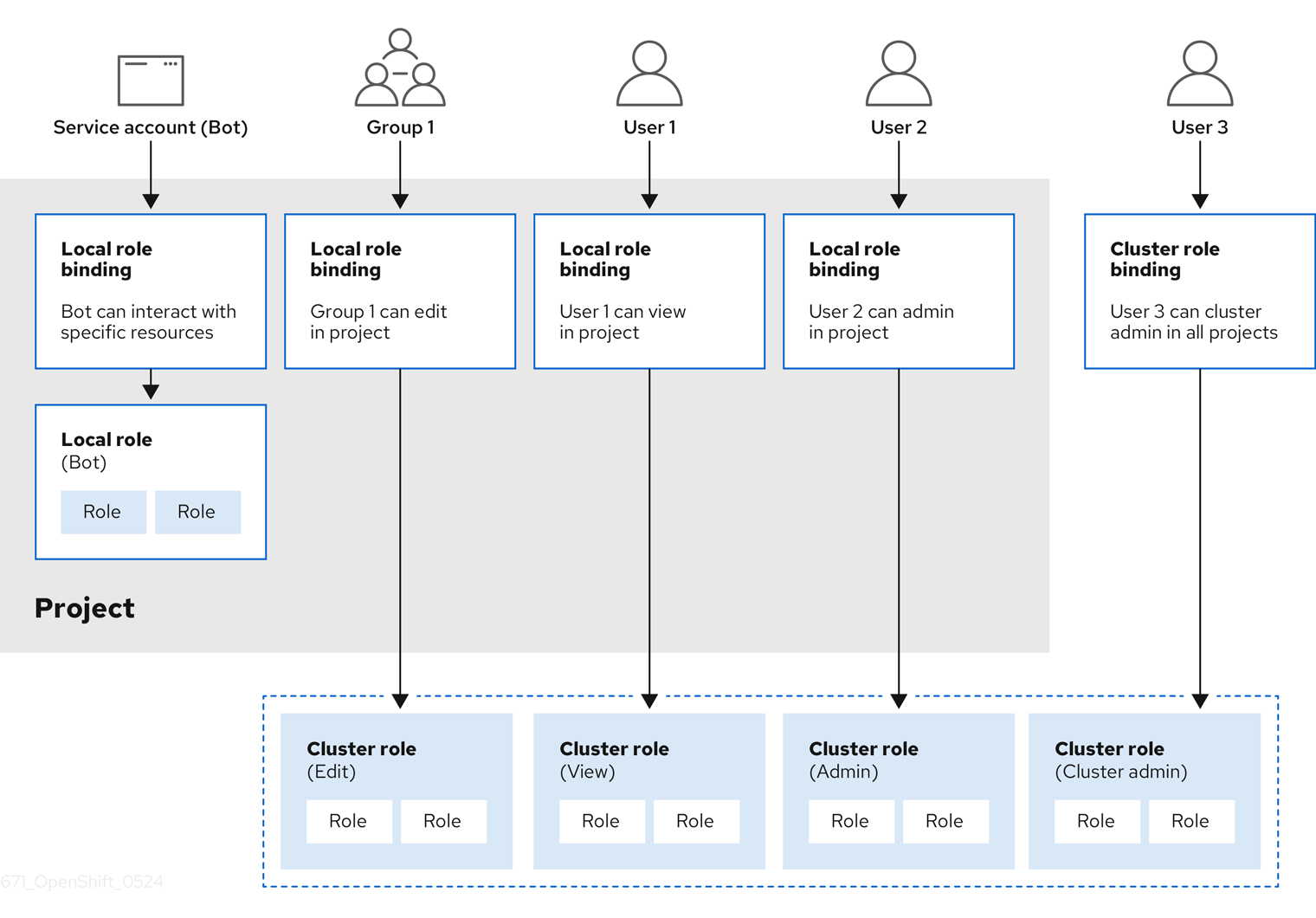
The get pods/exec, get pods/*, and get * rules grant execution privileges when they are applied to a role. Apply the principle of least privilege and assign only the minimal RBAC rights required for users and agents. For more information, see RBAC rules allow execution privileges.
10.2.1.2. Evaluating authorization
OpenShift Container Platform evaluates authorization by using:
- Identity
- The user name and list of groups that the user belongs to.
- Action
The action you perform. In most cases, this consists of:
- Project: The project you access. A project is a Kubernetes namespace with additional annotations that allows a community of users to organize and manage their content in isolation from other communities.
-
Verb : The action itself:
get,list,create,update,delete,deletecollection, orwatch. - Resource name: The API endpoint that you access.
- Bindings
- The full list of bindings, the associations between users or groups with a role.
OpenShift Container Platform evaluates authorization by using the following steps:
- The identity and the project-scoped action is used to find all bindings that apply to the user or their groups.
- Bindings are used to locate all the roles that apply.
- Roles are used to find all the rules that apply.
- The action is checked against each rule to find a match.
- If no matching rule is found, the action is then denied by default.
Remember that users and groups can be associated with, or bound to, multiple roles at the same time.
Project administrators can use the CLI to view local roles and bindings, including a matrix of the verbs and resources each are associated with.
The cluster role bound to the project administrator is limited in a project through a local binding. It is not bound cluster-wide like the cluster roles granted to the cluster-admin or system:admin.
Cluster roles are roles defined at the cluster level but can be bound either at the cluster level or at the project level.
10.2.1.2.1. Cluster role aggregation
The default admin, edit, view, and cluster-reader cluster roles support cluster role aggregation, where the cluster rules for each role are dynamically updated as new rules are created. This feature is relevant only if you extend the Kubernetes API by creating custom resources.
10.2.2. Projects and namespaces
A Kubernetes namespace provides a mechanism to scope resources in a cluster. The Kubernetes documentation has more information on namespaces.
Namespaces provide a unique scope for:
- Named resources to avoid basic naming collisions.
- Delegated management authority to trusted users.
- The ability to limit community resource consumption.
Most objects in the system are scoped by namespace, but some are excepted and have no namespace, including nodes and users.
A project is a Kubernetes namespace with additional annotations and is the central vehicle by which access to resources for regular users is managed. A project allows a community of users to organize and manage their content in isolation from other communities. Users must be given access to projects by administrators, or if allowed to create projects, automatically have access to their own projects.
Projects can have a separate name, displayName, and description.
-
The mandatory
nameis a unique identifier for the project and is most visible when using the CLI tools or API. The maximum name length is 63 characters. -
The optional
displayNameis how the project is displayed in the web console (defaults toname). -
The optional
descriptioncan be a more detailed description of the project and is also visible in the web console.
Each project scopes its own set of:
| Object | Description |
|---|---|
|
| Pods, services, replication controllers, etc. |
|
| Rules for which users can or cannot perform actions on objects. |
|
| Quotas for each kind of object that can be limited. |
|
| Service accounts act automatically with designated access to objects in the project. |
Cluster administrators can create projects and delegate administrative rights for the project to any member of the user community. Cluster administrators can also allow developers to create their own projects.
Developers and administrators can interact with projects by using the CLI or the web console.
10.2.3. Default projects
OpenShift Container Platform comes with a number of default projects, and projects starting with openshift- are the most essential to users. These projects host master components that run as pods and other infrastructure components. The pods created in these namespaces that have a critical pod annotation are considered critical, and the have guaranteed admission by kubelet. Pods created for master components in these namespaces are already marked as critical.
Do not run workloads in or share access to default projects. Default projects are reserved for running core cluster components.
The following default projects are considered highly privileged: default, kube-public, kube-system, openshift, openshift-infra, openshift-node, and other system-created projects that have the openshift.io/run-level label set to 0 or 1. Functionality that relies on admission plugins, such as pod security admission, security context constraints, cluster resource quotas, and image reference resolution, does not work in highly privileged projects.
10.2.4. Viewing cluster roles and bindings
You can use the oc CLI to view cluster roles and bindings by using the oc describe command.
Prerequisites
-
Install the
ocCLI. - Obtain permission to view the cluster roles and bindings.
Users with the cluster-admin default cluster role bound cluster-wide can perform any action on any resource, including viewing cluster roles and bindings.
Procedure
To view the cluster roles and their associated rule sets:
$ oc describe clusterrole.rbacExample output
Name: admin Labels: kubernetes.io/bootstrapping=rbac-defaults Annotations: rbac.authorization.kubernetes.io/autoupdate: true PolicyRule: Resources Non-Resource URLs Resource Names Verbs --------- ----------------- -------------- ----- .packages.apps.redhat.com [] [] [* create update patch delete get list watch] imagestreams [] [] [create delete deletecollection get list patch update watch create get list watch] imagestreams.image.openshift.io [] [] [create delete deletecollection get list patch update watch create get list watch] secrets [] [] [create delete deletecollection get list patch update watch get list watch create delete deletecollection patch update] buildconfigs/webhooks [] [] [create delete deletecollection get list patch update watch get list watch] buildconfigs [] [] [create delete deletecollection get list patch update watch get list watch] buildlogs [] [] [create delete deletecollection get list patch update watch get list watch] deploymentconfigs/scale [] [] [create delete deletecollection get list patch update watch get list watch] deploymentconfigs [] [] [create delete deletecollection get list patch update watch get list watch] imagestreamimages [] [] [create delete deletecollection get list patch update watch get list watch] imagestreammappings [] [] [create delete deletecollection get list patch update watch get list watch] imagestreamtags [] [] [create delete deletecollection get list patch update watch get list watch] processedtemplates [] [] [create delete deletecollection get list patch update watch get list watch] routes [] [] [create delete deletecollection get list patch update watch get list watch] templateconfigs [] [] [create delete deletecollection get list patch update watch get list watch] templateinstances [] [] [create delete deletecollection get list patch update watch get list watch] templates [] [] [create delete deletecollection get list patch update watch get list watch] deploymentconfigs.apps.openshift.io/scale [] [] [create delete deletecollection get list patch update watch get list watch] deploymentconfigs.apps.openshift.io [] [] [create delete deletecollection get list patch update watch get list watch] buildconfigs.build.openshift.io/webhooks [] [] [create delete deletecollection get list patch update watch get list watch] buildconfigs.build.openshift.io [] [] [create delete deletecollection get list patch update watch get list watch] buildlogs.build.openshift.io [] [] [create delete deletecollection get list patch update watch get list watch] imagestreamimages.image.openshift.io [] [] [create delete deletecollection get list patch update watch get list watch] imagestreammappings.image.openshift.io [] [] [create delete deletecollection get list patch update watch get list watch] imagestreamtags.image.openshift.io [] [] [create delete deletecollection get list patch update watch get list watch] routes.route.openshift.io [] [] [create delete deletecollection get list patch update watch get list watch] processedtemplates.template.openshift.io [] [] [create delete deletecollection get list patch update watch get list watch] templateconfigs.template.openshift.io [] [] [create delete deletecollection get list patch update watch get list watch] templateinstances.template.openshift.io [] [] [create delete deletecollection get list patch update watch get list watch] templates.template.openshift.io [] [] [create delete deletecollection get list patch update watch get list watch] serviceaccounts [] [] [create delete deletecollection get list patch update watch impersonate create delete deletecollection patch update get list watch] imagestreams/secrets [] [] [create delete deletecollection get list patch update watch] rolebindings [] [] [create delete deletecollection get list patch update watch] roles [] [] [create delete deletecollection get list patch update watch] rolebindings.authorization.openshift.io [] [] [create delete deletecollection get list patch update watch] roles.authorization.openshift.io [] [] [create delete deletecollection get list patch update watch] imagestreams.image.openshift.io/secrets [] [] [create delete deletecollection get list patch update watch] rolebindings.rbac.authorization.k8s.io [] [] [create delete deletecollection get list patch update watch] roles.rbac.authorization.k8s.io [] [] [create delete deletecollection get list patch update watch] networkpolicies.extensions [] [] [create delete deletecollection patch update create delete deletecollection get list patch update watch get list watch] networkpolicies.networking.k8s.io [] [] [create delete deletecollection patch update create delete deletecollection get list patch update watch get list watch] configmaps [] [] [create delete deletecollection patch update get list watch] endpoints [] [] [create delete deletecollection patch update get list watch] persistentvolumeclaims [] [] [create delete deletecollection patch update get list watch] pods [] [] [create delete deletecollection patch update get list watch] replicationcontrollers/scale [] [] [create delete deletecollection patch update get list watch] replicationcontrollers [] [] [create delete deletecollection patch update get list watch] services [] [] [create delete deletecollection patch update get list watch] daemonsets.apps [] [] [create delete deletecollection patch update get list watch] deployments.apps/scale [] [] [create delete deletecollection patch update get list watch] deployments.apps [] [] [create delete deletecollection patch update get list watch] replicasets.apps/scale [] [] [create delete deletecollection patch update get list watch] replicasets.apps [] [] [create delete deletecollection patch update get list watch] statefulsets.apps/scale [] [] [create delete deletecollection patch update get list watch] statefulsets.apps [] [] [create delete deletecollection patch update get list watch] horizontalpodautoscalers.autoscaling [] [] [create delete deletecollection patch update get list watch] cronjobs.batch [] [] [create delete deletecollection patch update get list watch] jobs.batch [] [] [create delete deletecollection patch update get list watch] daemonsets.extensions [] [] [create delete deletecollection patch update get list watch] deployments.extensions/scale [] [] [create delete deletecollection patch update get list watch] deployments.extensions [] [] [create delete deletecollection patch update get list watch] ingresses.extensions [] [] [create delete deletecollection patch update get list watch] replicasets.extensions/scale [] [] [create delete deletecollection patch update get list watch] replicasets.extensions [] [] [create delete deletecollection patch update get list watch] replicationcontrollers.extensions/scale [] [] [create delete deletecollection patch update get list watch] poddisruptionbudgets.policy [] [] [create delete deletecollection patch update get list watch] deployments.apps/rollback [] [] [create delete deletecollection patch update] deployments.extensions/rollback [] [] [create delete deletecollection patch update] catalogsources.operators.coreos.com [] [] [create update patch delete get list watch] clusterserviceversions.operators.coreos.com [] [] [create update patch delete get list watch] installplans.operators.coreos.com [] [] [create update patch delete get list watch] packagemanifests.operators.coreos.com [] [] [create update patch delete get list watch] subscriptions.operators.coreos.com [] [] [create update patch delete get list watch] buildconfigs/instantiate [] [] [create] buildconfigs/instantiatebinary [] [] [create] builds/clone [] [] [create] deploymentconfigrollbacks [] [] [create] deploymentconfigs/instantiate [] [] [create] deploymentconfigs/rollback [] [] [create] imagestreamimports [] [] [create] localresourceaccessreviews [] [] [create] localsubjectaccessreviews [] [] [create] podsecuritypolicyreviews [] [] [create] podsecuritypolicyselfsubjectreviews [] [] [create] podsecuritypolicysubjectreviews [] [] [create] resourceaccessreviews [] [] [create] routes/custom-host [] [] [create] subjectaccessreviews [] [] [create] subjectrulesreviews [] [] [create] deploymentconfigrollbacks.apps.openshift.io [] [] [create] deploymentconfigs.apps.openshift.io/instantiate [] [] [create] deploymentconfigs.apps.openshift.io/rollback [] [] [create] localsubjectaccessreviews.authorization.k8s.io [] [] [create] localresourceaccessreviews.authorization.openshift.io [] [] [create] localsubjectaccessreviews.authorization.openshift.io [] [] [create] resourceaccessreviews.authorization.openshift.io [] [] [create] subjectaccessreviews.authorization.openshift.io [] [] [create] subjectrulesreviews.authorization.openshift.io [] [] [create] buildconfigs.build.openshift.io/instantiate [] [] [create] buildconfigs.build.openshift.io/instantiatebinary [] [] [create] builds.build.openshift.io/clone [] [] [create] imagestreamimports.image.openshift.io [] [] [create] routes.route.openshift.io/custom-host [] [] [create] podsecuritypolicyreviews.security.openshift.io [] [] [create] podsecuritypolicyselfsubjectreviews.security.openshift.io [] [] [create] podsecuritypolicysubjectreviews.security.openshift.io [] [] [create] jenkins.build.openshift.io [] [] [edit view view admin edit view] builds [] [] [get create delete deletecollection get list patch update watch get list watch] builds.build.openshift.io [] [] [get create delete deletecollection get list patch update watch get list watch] projects [] [] [get delete get delete get patch update] projects.project.openshift.io [] [] [get delete get delete get patch update] namespaces [] [] [get get list watch] pods/attach [] [] [get list watch create delete deletecollection patch update] pods/exec [] [] [get list watch create delete deletecollection patch update] pods/portforward [] [] [get list watch create delete deletecollection patch update] pods/proxy [] [] [get list watch create delete deletecollection patch update] services/proxy [] [] [get list watch create delete deletecollection patch update] routes/status [] [] [get list watch update] routes.route.openshift.io/status [] [] [get list watch update] appliedclusterresourcequotas [] [] [get list watch] bindings [] [] [get list watch] builds/log [] [] [get list watch] deploymentconfigs/log [] [] [get list watch] deploymentconfigs/status [] [] [get list watch] events [] [] [get list watch] imagestreams/status [] [] [get list watch] limitranges [] [] [get list watch] namespaces/status [] [] [get list watch] pods/log [] [] [get list watch] pods/status [] [] [get list watch] replicationcontrollers/status [] [] [get list watch] resourcequotas/status [] [] [get list watch] resourcequotas [] [] [get list watch] resourcequotausages [] [] [get list watch] rolebindingrestrictions [] [] [get list watch] deploymentconfigs.apps.openshift.io/log [] [] [get list watch] deploymentconfigs.apps.openshift.io/status [] [] [get list watch] controllerrevisions.apps [] [] [get list watch] rolebindingrestrictions.authorization.openshift.io [] [] [get list watch] builds.build.openshift.io/log [] [] [get list watch] imagestreams.image.openshift.io/status [] [] [get list watch] appliedclusterresourcequotas.quota.openshift.io [] [] [get list watch] imagestreams/layers [] [] [get update get] imagestreams.image.openshift.io/layers [] [] [get update get] builds/details [] [] [update] builds.build.openshift.io/details [] [] [update] Name: basic-user Labels: <none> Annotations: openshift.io/description: A user that can get basic information about projects. rbac.authorization.kubernetes.io/autoupdate: true PolicyRule: Resources Non-Resource URLs Resource Names Verbs --------- ----------------- -------------- ----- selfsubjectrulesreviews [] [] [create] selfsubjectaccessreviews.authorization.k8s.io [] [] [create] selfsubjectrulesreviews.authorization.openshift.io [] [] [create] clusterroles.rbac.authorization.k8s.io [] [] [get list watch] clusterroles [] [] [get list] clusterroles.authorization.openshift.io [] [] [get list] storageclasses.storage.k8s.io [] [] [get list] users [] [~] [get] users.user.openshift.io [] [~] [get] projects [] [] [list watch] projects.project.openshift.io [] [] [list watch] projectrequests [] [] [list] projectrequests.project.openshift.io [] [] [list] Name: cluster-admin Labels: kubernetes.io/bootstrapping=rbac-defaults Annotations: rbac.authorization.kubernetes.io/autoupdate: true PolicyRule: Resources Non-Resource URLs Resource Names Verbs --------- ----------------- -------------- ----- *.* [] [] [*] [*] [] [*] ...To view the current set of cluster role bindings, which shows the users and groups that are bound to various roles:
$ oc describe clusterrolebinding.rbacExample output
Name: alertmanager-main Labels: <none> Annotations: <none> Role: Kind: ClusterRole Name: alertmanager-main Subjects: Kind Name Namespace ---- ---- --------- ServiceAccount alertmanager-main openshift-monitoring Name: basic-users Labels: <none> Annotations: rbac.authorization.kubernetes.io/autoupdate: true Role: Kind: ClusterRole Name: basic-user Subjects: Kind Name Namespace ---- ---- --------- Group system:authenticated Name: cloud-credential-operator-rolebinding Labels: <none> Annotations: <none> Role: Kind: ClusterRole Name: cloud-credential-operator-role Subjects: Kind Name Namespace ---- ---- --------- ServiceAccount default openshift-cloud-credential-operator Name: cluster-admin Labels: kubernetes.io/bootstrapping=rbac-defaults Annotations: rbac.authorization.kubernetes.io/autoupdate: true Role: Kind: ClusterRole Name: cluster-admin Subjects: Kind Name Namespace ---- ---- --------- Group system:masters Name: cluster-admins Labels: <none> Annotations: rbac.authorization.kubernetes.io/autoupdate: true Role: Kind: ClusterRole Name: cluster-admin Subjects: Kind Name Namespace ---- ---- --------- Group system:cluster-admins User system:admin Name: cluster-api-manager-rolebinding Labels: <none> Annotations: <none> Role: Kind: ClusterRole Name: cluster-api-manager-role Subjects: Kind Name Namespace ---- ---- --------- ServiceAccount default openshift-machine-api ...
10.2.5. Viewing local roles and bindings
You can use the oc CLI to view local roles and bindings by using the oc describe command.
Prerequisites
-
Install the
ocCLI. Obtain permission to view the local roles and bindings:
-
Users with the
cluster-admindefault cluster role bound cluster-wide can perform any action on any resource, including viewing local roles and bindings. -
Users with the
admindefault cluster role bound locally can view and manage roles and bindings in that project.
-
Users with the
Procedure
To view the current set of local role bindings, which show the users and groups that are bound to various roles for the current project:
$ oc describe rolebinding.rbacTo view the local role bindings for a different project, add the
-nflag to the command:$ oc describe rolebinding.rbac -n joe-projectExample output
Name: admin Labels: <none> Annotations: <none> Role: Kind: ClusterRole Name: admin Subjects: Kind Name Namespace ---- ---- --------- User kube:admin Name: system:deployers Labels: <none> Annotations: openshift.io/description: Allows deploymentconfigs in this namespace to rollout pods in this namespace. It is auto-managed by a controller; remove subjects to disa... Role: Kind: ClusterRole Name: system:deployer Subjects: Kind Name Namespace ---- ---- --------- ServiceAccount deployer joe-project Name: system:image-builders Labels: <none> Annotations: openshift.io/description: Allows builds in this namespace to push images to this namespace. It is auto-managed by a controller; remove subjects to disable. Role: Kind: ClusterRole Name: system:image-builder Subjects: Kind Name Namespace ---- ---- --------- ServiceAccount builder joe-project Name: system:image-pullers Labels: <none> Annotations: openshift.io/description: Allows all pods in this namespace to pull images from this namespace. It is auto-managed by a controller; remove subjects to disable. Role: Kind: ClusterRole Name: system:image-puller Subjects: Kind Name Namespace ---- ---- --------- Group system:serviceaccounts:joe-project
10.2.6. Adding roles to users
You can use the oc adm administrator CLI to manage the roles and bindings.
Binding, or adding, a role to users or groups gives the user or group the access that is granted by the role. You can add and remove roles to and from users and groups using oc adm policy commands.
You can bind any of the default cluster roles to local users or groups in your project.
Procedure
Add a role to a user in a specific project:
$ oc adm policy add-role-to-user <role> <user> -n <project>For example, you can add the
adminrole to thealiceuser injoeproject by running:$ oc adm policy add-role-to-user admin alice -n joeTipYou can alternatively apply the following YAML to add the role to the user:
apiVersion: rbac.authorization.k8s.io/v1 kind: RoleBinding metadata: name: admin-0 namespace: joe roleRef: apiGroup: rbac.authorization.k8s.io kind: ClusterRole name: admin subjects: - apiGroup: rbac.authorization.k8s.io kind: User name: aliceView the local role bindings and verify the addition in the output:
$ oc describe rolebinding.rbac -n <project>For example, to view the local role bindings for the
joeproject:$ oc describe rolebinding.rbac -n joeExample output
Name: admin Labels: <none> Annotations: <none> Role: Kind: ClusterRole Name: admin Subjects: Kind Name Namespace ---- ---- --------- User kube:admin Name: admin-0 Labels: <none> Annotations: <none> Role: Kind: ClusterRole Name: admin Subjects: Kind Name Namespace ---- ---- --------- User alice1 Name: system:deployers Labels: <none> Annotations: openshift.io/description: Allows deploymentconfigs in this namespace to rollout pods in this namespace. It is auto-managed by a controller; remove subjects to disa... Role: Kind: ClusterRole Name: system:deployer Subjects: Kind Name Namespace ---- ---- --------- ServiceAccount deployer joe Name: system:image-builders Labels: <none> Annotations: openshift.io/description: Allows builds in this namespace to push images to this namespace. It is auto-managed by a controller; remove subjects to disable. Role: Kind: ClusterRole Name: system:image-builder Subjects: Kind Name Namespace ---- ---- --------- ServiceAccount builder joe Name: system:image-pullers Labels: <none> Annotations: openshift.io/description: Allows all pods in this namespace to pull images from this namespace. It is auto-managed by a controller; remove subjects to disable. Role: Kind: ClusterRole Name: system:image-puller Subjects: Kind Name Namespace ---- ---- --------- Group system:serviceaccounts:joe- 1
- The
aliceuser has been added to theadminsRoleBinding.
10.2.7. Creating a local role
You can create a local role for a project and then bind it to a user.
Procedure
To create a local role for a project, run the following command:
$ oc create role <name> --verb=<verb> --resource=<resource> -n <project>In this command, specify:
-
<name>, the local role’s name -
<verb>, a comma-separated list of the verbs to apply to the role -
<resource>, the resources that the role applies to -
<project>, the project name
For example, to create a local role that allows a user to view pods in the
blueproject, run the following command:$ oc create role podview --verb=get --resource=pod -n blue-
To bind the new role to a user, run the following command:
$ oc adm policy add-role-to-user podview user2 --role-namespace=blue -n blue
10.2.8. Creating a cluster role
You can create a cluster role.
Procedure
To create a cluster role, run the following command:
$ oc create clusterrole <name> --verb=<verb> --resource=<resource>In this command, specify:
-
<name>, the local role’s name -
<verb>, a comma-separated list of the verbs to apply to the role -
<resource>, the resources that the role applies to
For example, to create a cluster role that allows a user to view pods, run the following command:
$ oc create clusterrole podviewonly --verb=get --resource=pod-
10.2.9. Local role binding commands
When you manage a user or group’s associated roles for local role bindings using the following operations, a project may be specified with the -n flag. If it is not specified, then the current project is used.
You can use the following commands for local RBAC management.
| Command | Description |
|---|---|
|
| Indicates which users can perform an action on a resource. |
|
| Binds a specified role to specified users in the current project. |
|
| Removes a given role from specified users in the current project. |
|
| Removes specified users and all of their roles in the current project. |
|
| Binds a given role to specified groups in the current project. |
|
| Removes a given role from specified groups in the current project. |
|
| Removes specified groups and all of their roles in the current project. |
10.2.10. Cluster role binding commands
You can also manage cluster role bindings using the following operations. The -n flag is not used for these operations because cluster role bindings use non-namespaced resources.
| Command | Description |
|---|---|
|
| Binds a given role to specified users for all projects in the cluster. |
|
| Removes a given role from specified users for all projects in the cluster. |
|
| Binds a given role to specified groups for all projects in the cluster. |
|
| Removes a given role from specified groups for all projects in the cluster. |
10.2.11. Creating a cluster admin
The cluster-admin role is required to perform administrator level tasks on the OpenShift Container Platform cluster, such as modifying cluster resources.
Prerequisites
- You must have created a user to define as the cluster admin.
Procedure
Define the user as a cluster admin:
$ oc adm policy add-cluster-role-to-user cluster-admin <user>
10.2.12. Cluster role bindings for unauthenticated groups
Before OpenShift Container Platform 4.16, unauthenticated groups were allowed access to some cluster roles. Clusters updated from versions before OpenShift Container Platform 4.16 retain this access for unauthenticated groups.
For security reasons OpenShift Container Platform 4.16 does not allow unauthenticated groups to have default access to cluster roles.
There are use cases where it might be necessary to add system:unauthenticated to a cluster role.
Cluster administrators can add unauthenticated users to the following cluster roles:
-
system:scope-impersonation -
system:webhook -
system:oauth-token-deleter -
self-access-reviewer
Always verify compliance with your organization’s security standards when modifying unauthenticated access.
10.2.13. Adding unauthenticated groups to cluster roles
As a cluster administrator, you can add unauthenticated users to the following cluster roles in OpenShift Container Platform by creating a cluster role binding. Unauthenticated users do not have access to non-public cluster roles. This should only be done in specific use cases when necessary.
You can add unauthenticated users to the following cluster roles:
-
system:scope-impersonation -
system:webhook -
system:oauth-token-deleter -
self-access-reviewer
Always verify compliance with your organization’s security standards when modifying unauthenticated access.
Prerequisites
-
You have access to the cluster as a user with the
cluster-adminrole. -
You have installed the OpenShift CLI (
oc).
Procedure
Create a YAML file named
add-<cluster_role>-unauth.yamland add the following content:apiVersion: rbac.authorization.k8s.io/v1 kind: ClusterRoleBinding metadata: annotations: rbac.authorization.kubernetes.io/autoupdate: "true" name: <cluster_role>access-unauthenticated roleRef: apiGroup: rbac.authorization.k8s.io kind: ClusterRole name: <cluster_role> subjects: - apiGroup: rbac.authorization.k8s.io kind: Group name: system:unauthenticatedApply the configuration by running the following command:
$ oc apply -f add-<cluster_role>.yaml
10.3. The kubeadmin user
OpenShift Container Platform creates a cluster administrator, kubeadmin, after the installation process completes.
This user has the cluster-admin role automatically applied and is treated as the root user for the cluster. The password is dynamically generated and unique to your OpenShift Container Platform environment. After installation completes the password is provided in the installation program’s output. For example:
INFO Install complete!
INFO Run 'export KUBECONFIG=<your working directory>/auth/kubeconfig' to manage the cluster with 'oc', the OpenShift CLI.
INFO The cluster is ready when 'oc login -u kubeadmin -p <provided>' succeeds (wait a few minutes).
INFO Access the OpenShift web-console here: https://console-openshift-console.apps.demo1.openshift4-beta-abcorp.com
INFO Login to the console with user: kubeadmin, password: <provided>10.3.1. Removing the kubeadmin user
After you define an identity provider and create a new cluster-admin user, you can remove the kubeadmin to improve cluster security.
If you follow this procedure before another user is a cluster-admin, then OpenShift Container Platform must be reinstalled. It is not possible to undo this command.
Prerequisites
- You must have configured at least one identity provider.
-
You must have added the
cluster-adminrole to a user. - You must be logged in as an administrator.
Procedure
Remove the
kubeadminsecrets:$ oc delete secrets kubeadmin -n kube-system
10.4. Populating OperatorHub from mirrored Operator catalogs
If you mirrored Operator catalogs for use with disconnected clusters, you can populate OperatorHub with the Operators from your mirrored catalogs. You can use the generated manifests from the mirroring process to create the required ImageContentSourcePolicy and CatalogSource objects.
10.4.1. Prerequisites
10.4.1.1. Creating the ImageContentSourcePolicy object
After mirroring Operator catalog content to your mirror registry, create the required ImageContentSourcePolicy (ICSP) object. The ICSP object configures nodes to translate between the image references stored in Operator manifests and the mirrored registry.
Procedure
On a host with access to the disconnected cluster, create the ICSP by running the following command to specify the
imageContentSourcePolicy.yamlfile in your manifests directory:$ oc create -f <path/to/manifests/dir>/imageContentSourcePolicy.yamlwhere
<path/to/manifests/dir>is the path to the manifests directory for your mirrored content.You can now create a
CatalogSourceobject to reference your mirrored index image and Operator content.
10.4.1.2. Adding a catalog source to a cluster
Adding a catalog source to an OpenShift Container Platform cluster enables the discovery and installation of Operators for users. Cluster administrators can create a CatalogSource object that references an index image. OperatorHub uses catalog sources to populate the user interface.
Alternatively, you can use the web console to manage catalog sources. From the Administration → Cluster Settings → Configuration → OperatorHub page, click the Sources tab, where you can create, update, delete, disable, and enable individual sources.
Prerequisites
- You built and pushed an index image to a registry.
-
You have access to the cluster as a user with the
cluster-adminrole.
Procedure
Create a
CatalogSourceobject that references your index image. If you used theoc adm catalog mirrorcommand to mirror your catalog to a target registry, you can use the generatedcatalogSource.yamlfile in your manifests directory as a starting point.Modify the following to your specifications and save it as a
catalogSource.yamlfile:apiVersion: operators.coreos.com/v1alpha1 kind: CatalogSource metadata: name: my-operator-catalog1 namespace: openshift-marketplace2 spec: sourceType: grpc grpcPodConfig: securityContextConfig: <security_mode>3 image: <registry>/<namespace>/redhat-operator-index:v4.164 displayName: My Operator Catalog publisher: <publisher_name>5 updateStrategy: registryPoll:6 interval: 30m- 1
- If you mirrored content to local files before uploading to a registry, remove any backslash (
/) characters from themetadata.namefield to avoid an "invalid resource name" error when you create the object. - 2
- If you want the catalog source to be available globally to users in all namespaces, specify the
openshift-marketplacenamespace. Otherwise, you can specify a different namespace for the catalog to be scoped and available only for that namespace. - 3
- Specify the value of
legacyorrestricted. If the field is not set, the default value islegacy. In a future OpenShift Container Platform release, it is planned that the default value will berestricted.NoteIf your catalog cannot run with
restrictedpermissions, it is recommended that you manually set this field tolegacy. - 4
- Specify your index image. If you specify a tag after the image name, for example
:v4.16, the catalog source pod uses an image pull policy ofAlways, meaning the pod always pulls the image prior to starting the container. If you specify a digest, for example@sha256:<id>, the image pull policy isIfNotPresent, meaning the pod pulls the image only if it does not already exist on the node. - 5
- Specify your name or an organization name publishing the catalog.
- 6
- Catalog sources can automatically check for new versions to keep up to date.
Use the file to create the
CatalogSourceobject:$ oc apply -f catalogSource.yaml
Verify the following resources are created successfully.
Check the pods:
$ oc get pods -n openshift-marketplaceExample output
NAME READY STATUS RESTARTS AGE my-operator-catalog-6njx6 1/1 Running 0 28s marketplace-operator-d9f549946-96sgr 1/1 Running 0 26hCheck the catalog source:
$ oc get catalogsource -n openshift-marketplaceExample output
NAME DISPLAY TYPE PUBLISHER AGE my-operator-catalog My Operator Catalog grpc 5sCheck the package manifest:
$ oc get packagemanifest -n openshift-marketplaceExample output
NAME CATALOG AGE jaeger-product My Operator Catalog 93s
You can now install the Operators from the OperatorHub page on your OpenShift Container Platform web console.
10.5. About Operator installation with OperatorHub
OperatorHub is a user interface for discovering Operators; it works in conjunction with Operator Lifecycle Manager (OLM), which installs and manages Operators on a cluster.
As a cluster administrator, you can install an Operator from OperatorHub by using the OpenShift Container Platform web console or CLI. Subscribing an Operator to one or more namespaces makes the Operator available to developers on your cluster.
During installation, you must determine the following initial settings for the Operator:
- Installation Mode
- Choose All namespaces on the cluster (default) to have the Operator installed on all namespaces or choose individual namespaces, if available, to only install the Operator on selected namespaces. This example chooses All namespaces… to make the Operator available to all users and projects.
- Update Channel
- If an Operator is available through multiple channels, you can choose which channel you want to subscribe to. For example, to deploy from the stable channel, if available, select it from the list.
- Approval Strategy
You can choose automatic or manual updates.
If you choose automatic updates for an installed Operator, when a new version of that Operator is available in the selected channel, Operator Lifecycle Manager (OLM) automatically upgrades the running instance of your Operator without human intervention.
If you select manual updates, when a newer version of an Operator is available, OLM creates an update request. As a cluster administrator, you must then manually approve that update request to have the Operator updated to the new version.
10.5.1. Installing from OperatorHub by using the web console
You can install and subscribe to an Operator from OperatorHub by using the OpenShift Container Platform web console.
Prerequisites
-
Access to an OpenShift Container Platform cluster using an account with
cluster-adminpermissions.
Procedure
- Navigate in the web console to the Operators → OperatorHub page.
Scroll or type a keyword into the Filter by keyword box to find the Operator you want. For example, type
jaegerto find the Jaeger Operator.You can also filter options by Infrastructure Features. For example, select Disconnected if you want to see Operators that work in disconnected environments, also known as restricted network environments.
Select the Operator to display additional information.
NoteChoosing a Community Operator warns that Red Hat does not certify Community Operators; you must acknowledge the warning before continuing.
- Read the information about the Operator and click Install.
On the Install Operator page, configure your Operator installation:
If you want to install a specific version of an Operator, select an Update channel and Version from the lists. You can browse the various versions of an Operator across any channels it might have, view the metadata for that channel and version, and select the exact version you want to install.
NoteThe version selection defaults to the latest version for the channel selected. If the latest version for the channel is selected, the Automatic approval strategy is enabled by default. Otherwise, Manual approval is required when not installing the latest version for the selected channel.
Installing an Operator with Manual approval causes all Operators installed within the namespace to function with the Manual approval strategy and all Operators are updated together. If you want to update Operators independently, install Operators into separate namespaces.
Confirm the installation mode for the Operator:
-
All namespaces on the cluster (default) installs the Operator in the default
openshift-operatorsnamespace to watch and be made available to all namespaces in the cluster. This option is not always available. - A specific namespace on the cluster allows you to choose a specific, single namespace in which to install the Operator. The Operator will only watch and be made available for use in this single namespace.
-
All namespaces on the cluster (default) installs the Operator in the default
For clusters on cloud providers with token authentication enabled:
- If the cluster uses AWS STS (STS Mode in the web console), enter the Amazon Resource Name (ARN) of the AWS IAM role of your service account in the role ARN field. To create the role’s ARN, follow the procedure described in Preparing AWS account.
- If the cluster uses Microsoft Entra Workload ID (Workload Identity / Federated Identity Mode in the web console), add the client ID, tenant ID, and subscription ID in the appropriate field.
For Update approval, select either the Automatic or Manual approval strategy.
ImportantIf the web console shows that the cluster uses AWS STS or Microsoft Entra Workload ID, you must set Update approval to Manual.
Subscriptions with automatic update approvals are not recommended because there might be permission changes to make prior to updating. Subscriptions with manual update approvals ensure that administrators have the opportunity to verify the permissions of the later version and take any necessary steps prior to update.
Click Install to make the Operator available to the selected namespaces on this OpenShift Container Platform cluster:
If you selected a Manual approval strategy, the upgrade status of the subscription remains Upgrading until you review and approve the install plan.
After approving on the Install Plan page, the subscription upgrade status moves to Up to date.
- If you selected an Automatic approval strategy, the upgrade status should resolve to Up to date without intervention.
Verification
After the upgrade status of the subscription is Up to date, select Operators → Installed Operators to verify that the cluster service version (CSV) of the installed Operator eventually shows up. The Status should eventually resolve to Succeeded in the relevant namespace.
NoteFor the All namespaces… installation mode, the status resolves to Succeeded in the
openshift-operatorsnamespace, but the status is Copied if you check in other namespaces.If it does not:
-
Check the logs in any pods in the
openshift-operatorsproject (or other relevant namespace if A specific namespace… installation mode was selected) on the Workloads → Pods page that are reporting issues to troubleshoot further.
-
Check the logs in any pods in the
When the Operator is installed, the metadata indicates which channel and version are installed.
NoteThe Channel and Version dropdown menus are still available for viewing other version metadata in this catalog context.
10.5.2. Installing from OperatorHub by using the CLI
Instead of using the OpenShift Container Platform web console, you can install an Operator from OperatorHub by using the CLI. Use the oc command to create or update a Subscription object.
For SingleNamespace install mode, you must also ensure an appropriate Operator group exists in the related namespace. An Operator group, defined by an OperatorGroup object, selects target namespaces in which to generate required RBAC access for all Operators in the same namespace as the Operator group.
In most cases, the web console method of this procedure is preferred because it automates tasks in the background, such as handling the creation of OperatorGroup and Subscription objects automatically when choosing SingleNamespace mode.
Prerequisites
-
Access to an OpenShift Container Platform cluster using an account with
cluster-adminpermissions. -
You have installed the OpenShift CLI (
oc).
Procedure
View the list of Operators available to the cluster from OperatorHub:
$ oc get packagemanifests -n openshift-marketplaceExample 10.1. Example output
NAME CATALOG AGE 3scale-operator Red Hat Operators 91m advanced-cluster-management Red Hat Operators 91m amq7-cert-manager Red Hat Operators 91m # ... couchbase-enterprise-certified Certified Operators 91m crunchy-postgres-operator Certified Operators 91m mongodb-enterprise Certified Operators 91m # ... etcd Community Operators 91m jaeger Community Operators 91m kubefed Community Operators 91m # ...Note the catalog for your desired Operator.
Inspect your desired Operator to verify its supported install modes and available channels:
$ oc describe packagemanifests <operator_name> -n openshift-marketplaceExample 10.2. Example output
# ... Kind: PackageManifest # ... Install Modes:1 Supported: true Type: OwnNamespace Supported: true Type: SingleNamespace Supported: false Type: MultiNamespace Supported: true Type: AllNamespaces # ... Entries: Name: example-operator.v3.7.11 Version: 3.7.11 Name: example-operator.v3.7.10 Version: 3.7.10 Name: stable-3.72 # ... Entries: Name: example-operator.v3.8.5 Version: 3.8.5 Name: example-operator.v3.8.4 Version: 3.8.4 Name: stable-3.83 Default Channel: stable-3.84 TipYou can print an Operator’s version and channel information in YAML format by running the following command:
$ oc get packagemanifests <operator_name> -n <catalog_namespace> -o yamlIf more than one catalog is installed in a namespace, run the following command to look up the available versions and channels of an Operator from a specific catalog:
$ oc get packagemanifest \ --selector=catalog=<catalogsource_name> \ --field-selector metadata.name=<operator_name> \ -n <catalog_namespace> -o yamlImportantIf you do not specify the Operator’s catalog, running the
oc get packagemanifestandoc describe packagemanifestcommands might return a package from an unexpected catalog if the following conditions are met:- Multiple catalogs are installed in the same namespace.
- The catalogs contain the same Operators or Operators with the same name.
If the Operator you intend to install supports the
AllNamespacesinstall mode, and you choose to use this mode, skip this step, because theopenshift-operatorsnamespace already has an appropriate Operator group in place by default, calledglobal-operators.If the Operator you intend to install supports the
SingleNamespaceinstall mode, and you choose to use this mode, you must ensure an appropriate Operator group exists in the related namespace. If one does not exist, you can create create one by following these steps:ImportantYou can only have one Operator group per namespace. For more information, see "Operator groups".
Create an
OperatorGroupobject YAML file, for exampleoperatorgroup.yaml, forSingleNamespaceinstall mode:Example
OperatorGroupobject forSingleNamespaceinstall modeapiVersion: operators.coreos.com/v1 kind: OperatorGroup metadata: name: <operatorgroup_name> namespace: <namespace>1 spec: targetNamespaces: - <namespace>2 Create the
OperatorGroupobject:$ oc apply -f operatorgroup.yaml
Create a
Subscriptionobject to subscribe a namespace to an Operator:Create a YAML file for the
Subscriptionobject, for examplesubscription.yaml:NoteIf you want to subscribe to a specific version of an Operator, set the
startingCSVfield to the desired version and set theinstallPlanApprovalfield toManualto prevent the Operator from automatically upgrading if a later version exists in the catalog. For details, see the following "ExampleSubscriptionobject with a specific starting Operator version".Example 10.3. Example
SubscriptionobjectapiVersion: operators.coreos.com/v1alpha1 kind: Subscription metadata: name: <subscription_name> namespace: <namespace_per_install_mode>1 spec: channel: <channel_name>2 name: <operator_name>3 source: <catalog_name>4 sourceNamespace: <catalog_source_namespace>5 config: env:6 - name: ARGS value: "-v=10" envFrom:7 - secretRef: name: license-secret volumes:8 - name: <volume_name> configMap: name: <configmap_name> volumeMounts:9 - mountPath: <directory_name> name: <volume_name> tolerations:10 - operator: "Exists" resources:11 requests: memory: "64Mi" cpu: "250m" limits: memory: "128Mi" cpu: "500m" nodeSelector:12 foo: bar- 1
- For default
AllNamespacesinstall mode usage, specify theopenshift-operatorsnamespace. Alternatively, you can specify a custom global namespace, if you have created one. ForSingleNamespaceinstall mode usage, specify the relevant single namespace. - 2
- Name of the channel to subscribe to.
- 3
- Name of the Operator to subscribe to.
- 4
- Name of the catalog source that provides the Operator.
- 5
- Namespace of the catalog source. Use
openshift-marketplacefor the default OperatorHub catalog sources. - 6
- The
envparameter defines a list of environment variables that must exist in all containers in the pod created by OLM. - 7
- The
envFromparameter defines a list of sources to populate environment variables in the container. - 8
- The
volumesparameter defines a list of volumes that must exist on the pod created by OLM. - 9
- The
volumeMountsparameter defines a list of volume mounts that must exist in all containers in the pod created by OLM. If avolumeMountreferences avolumethat does not exist, OLM fails to deploy the Operator. - 10
- The
tolerationsparameter defines a list of tolerations for the pod created by OLM. - 11
- The
resourcesparameter defines resource constraints for all the containers in the pod created by OLM. - 12
- The
nodeSelectorparameter defines aNodeSelectorfor the pod created by OLM.
Example 10.4. Example
Subscriptionobject with a specific starting Operator versionapiVersion: operators.coreos.com/v1alpha1 kind: Subscription metadata: name: example-operator namespace: example-operator spec: channel: stable-3.7 installPlanApproval: Manual1 name: example-operator source: custom-operators sourceNamespace: openshift-marketplace startingCSV: example-operator.v3.7.102 - 1
- Set the approval strategy to
Manualin case your specified version is superseded by a later version in the catalog. This plan prevents an automatic upgrade to a later version and requires manual approval before the starting CSV can complete the installation. - 2
- Set a specific version of an Operator CSV.
For clusters on cloud providers with token authentication enabled, configure your
Subscriptionobject by following these steps:Ensure the
Subscriptionobject is set to manual update approvals:kind: Subscription # ... spec: installPlanApproval: Manual1 - 1
- Subscriptions with automatic update approvals are not recommended because there might be permission changes to make prior to updating. Subscriptions with manual update approvals ensure that administrators have the opportunity to verify the permissions of the later version and take any necessary steps prior to update.
Include the relevant cloud provider-specific fields in the
Subscriptionobject’sconfigsection:If the cluster is in AWS STS mode, include the following fields:
kind: Subscription # ... spec: config: env: - name: ROLEARN value: "<role_arn>"1 - 1
- Include the role ARN details.
If the cluster is in Microsoft Entra Workload ID mode, include the following fields:
kind: Subscription # ... spec: config: env: - name: CLIENTID value: "<client_id>"1 - name: TENANTID value: "<tenant_id>"2 - name: SUBSCRIPTIONID value: "<subscription_id>"3 where:
<client_id>- Is the client ID.
<tenant_id>- Is the tenant ID.
<subscription_id>- Is the subscription ID.
Create the
Subscriptionobject by running the following command:$ oc apply -f subscription.yaml
-
If you set the
installPlanApprovalfield toManual, manually approve the pending install plan to complete the Operator installation. For more information, see "Manually approving a pending Operator update".
At this point, OLM is now aware of the selected Operator. A cluster service version (CSV) for the Operator should appear in the target namespace, and APIs provided by the Operator should be available for creation.
Verification
Check the status of the
Subscriptionobject for your installed Operator by running the following command:$ oc describe subscription <subscription_name> -n <namespace>If you created an Operator group for
SingleNamespaceinstall mode, check the status of theOperatorGroupobject by running the following command:$ oc describe operatorgroup <operatorgroup_name> -n <namespace>
Chapter 11. Changing the cloud provider credentials configuration
For supported configurations, you can change how OpenShift Container Platform authenticates with your cloud provider.
To determine which cloud credentials strategy your cluster uses, see Determining the Cloud Credential Operator mode.
11.1. Rotating or removing cloud provider credentials
After installing OpenShift Container Platform, some organizations require the rotation or removal of the cloud provider credentials that were used during the initial installation.
To allow the cluster to use the new credentials, you must update the secrets that the Cloud Credential Operator (CCO) uses to manage cloud provider credentials.
11.1.1. Rotating cloud provider credentials with the Cloud Credential Operator utility
The Cloud Credential Operator (CCO) utility ccoctl supports updating secrets for clusters installed on IBM Cloud®.
11.1.1.1. Rotating API keys
You can rotate API keys for your existing service IDs and update the corresponding secrets.
Prerequisites
-
You have configured the
ccoctlbinary. - You have existing service IDs in a live OpenShift Container Platform cluster installed.
Procedure
Use the
ccoctlutility to rotate your API keys for the service IDs and update the secrets:$ ccoctl <provider_name> refresh-keys \1 --kubeconfig <openshift_kubeconfig_file> \2 --credentials-requests-dir <path_to_credential_requests_directory> \3 --name <name>4 NoteIf your cluster uses Technology Preview features that are enabled by the
TechPreviewNoUpgradefeature set, you must include the--enable-tech-previewparameter.
11.1.2. Rotating cloud provider credentials manually
If your cloud provider credentials are changed for any reason, you must manually update the secret that the Cloud Credential Operator (CCO) uses to manage cloud provider credentials.
The process for rotating cloud credentials depends on the mode that the CCO is configured to use. After you rotate credentials for a cluster that is using mint mode, you must manually remove the component credentials that were created by the removed credential.
Prerequisites
Your cluster is installed on a platform that supports rotating cloud credentials manually with the CCO mode that you are using:
- For mint mode, Amazon Web Services (AWS) and Google Cloud are supported.
- For passthrough mode, Amazon Web Services (AWS), Microsoft Azure, Google Cloud, Red Hat OpenStack Platform (RHOSP), and VMware vSphere are supported.
- You have changed the credentials that are used to interface with your cloud provider.
- The new credentials have sufficient permissions for the mode CCO is configured to use in your cluster.
Procedure
- In the Administrator perspective of the web console, navigate to Workloads → Secrets.
In the table on the Secrets page, find the root secret for your cloud provider.
Expand Platform Secret name AWS
aws-credsAzure
azure-credentialsGoogle Cloud
gcp-credentialsRHOSP
openstack-credentialsVMware vSphere
vsphere-creds-
Click the Options menu
 in the same row as the secret and select Edit Secret.
- Record the contents of the Value field or fields. You can use this information to verify that the value is different after updating the credentials.
- Update the text in the Value field or fields with the new authentication information for your cloud provider, and then click Save.
If you are updating the credentials for a vSphere cluster that does not have the vSphere CSI Driver Operator enabled, you must force a rollout of the Kubernetes controller manager to apply the updated credentials.
NoteIf the vSphere CSI Driver Operator is enabled, this step is not required.
To apply the updated vSphere credentials, log in to the OpenShift Container Platform CLI as a user with the
cluster-adminrole and run the following command:$ oc patch kubecontrollermanager cluster \ -p='{"spec": {"forceRedeploymentReason": "recovery-'"$( date )"'"}}' \ --type=mergeWhile the credentials are rolling out, the status of the Kubernetes Controller Manager Operator reports
Progressing=true. To view the status, run the following command:$ oc get co kube-controller-managerIf the CCO for your cluster is configured to use mint mode, delete each component secret that is referenced by the individual
CredentialsRequestobjects.-
Log in to the OpenShift Container Platform CLI as a user with the
cluster-adminrole. Get the names and namespaces of all referenced component secrets:
$ oc -n openshift-cloud-credential-operator get CredentialsRequest \ -o json | jq -r '.items[] | select (.spec.providerSpec.kind=="<provider_spec>") | .spec.secretRef'where
<provider_spec>is the corresponding value for your cloud provider:-
AWS:
AWSProviderSpec -
Google Cloud:
GCPProviderSpec
Partial example output for AWS
{ "name": "ebs-cloud-credentials", "namespace": "openshift-cluster-csi-drivers" } { "name": "cloud-credential-operator-iam-ro-creds", "namespace": "openshift-cloud-credential-operator" }-
AWS:
Delete each of the referenced component secrets:
$ oc delete secret <secret_name> \1 -n <secret_namespace>2 Example deletion of an AWS secret
$ oc delete secret ebs-cloud-credentials -n openshift-cluster-csi-driversYou do not need to manually delete the credentials from your provider console. Deleting the referenced component secrets will cause the CCO to delete the existing credentials from the platform and create new ones.
-
Log in to the OpenShift Container Platform CLI as a user with the
Verification
To verify that the credentials have changed:
- In the Administrator perspective of the web console, navigate to Workloads → Secrets.
- Verify that the contents of the Value field or fields have changed.
11.1.3. Removing cloud provider credentials
For clusters that use the Cloud Credential Operator (CCO) in mint mode, the administrator-level credential is stored in the kube-system namespace. The CCO uses the admin credential to process the CredentialsRequest objects in the cluster and create users for components with limited permissions.
After installing an OpenShift Container Platform cluster with the CCO in mint mode, you can remove the administrator-level credential secret from the kube-system namespace in the cluster. The CCO only requires the administrator-level credential during changes that require reconciling new or modified CredentialsRequest custom resources, such as minor cluster version updates.
Before performing a minor version cluster update (for example, updating from OpenShift Container Platform 4.16 to 4.17), you must reinstate the credential secret with the administrator-level credential. If the credential is not present, the update might be blocked.
Prerequisites
- Your cluster is installed on a platform that supports removing cloud credentials from the CCO. Supported platforms are AWS and Google Cloud.
Procedure
- In the Administrator perspective of the web console, navigate to Workloads → Secrets.
In the table on the Secrets page, find the root secret for your cloud provider.
Expand Platform Secret name AWS
aws-credsGoogle Cloud
gcp-credentials-
Click the Options menu
in the same row as the secret and select Delete Secret.
11.2. Enabling token-based authentication
After installing an OpenShift Container Platform cluster on Microsoft Azure or Amazon Web Services (AWS), you can enable Microsoft Entra Workload ID or Security Token Service (STS) to use short-term credentials.
11.2.1. Configuring the Cloud Credential Operator utility
To configure an existing cluster to create and manage cloud credentials from outside of the cluster, extract and prepare the Cloud Credential Operator utility (ccoctl) binary.
The ccoctl utility is a Linux binary that must run in a Linux environment.
Prerequisites
- You have access to an OpenShift Container Platform account with cluster administrator access.
-
You have installed the OpenShift CLI (
oc).
Procedure
Set a variable for the OpenShift Container Platform release image by running the following command:
$ RELEASE_IMAGE=$(oc get clusterversion -o jsonpath={..desired.image})Obtain the CCO container image from the OpenShift Container Platform release image by running the following command:
$ CCO_IMAGE=$(oc adm release info --image-for='cloud-credential-operator' $RELEASE_IMAGE -a ~/.pull-secret)NoteEnsure that the architecture of the
$RELEASE_IMAGEmatches the architecture of the environment in which you will use theccoctltool.Extract the
ccoctlbinary from the CCO container image within the OpenShift Container Platform release image by running the following command:$ oc image extract $CCO_IMAGE \ --file="/usr/bin/ccoctl.<rhel_version>" \1 -a ~/.pull-secret- 1
- For
<rhel_version>, specify the value that corresponds to the version of Red Hat Enterprise Linux (RHEL) that the host uses. If no value is specified,ccoctl.rhel8is used by default. The following values are valid:-
rhel8: Specify this value for hosts that use RHEL 8. -
rhel9: Specify this value for hosts that use RHEL 9.
-
NoteThe
ccoctlbinary is created in the directory from where you executed the command and not in/usr/bin/. You must rename the directory or move theccoctl.<rhel_version>binary toccoctl.Change the permissions to make
ccoctlexecutable by running the following command:$ chmod 775 ccoctl
Verification
To verify that
ccoctlis ready to use, display the help file. Use a relative file name when you run the command, for example:$ ./ccoctlExample output
OpenShift credentials provisioning tool Usage: ccoctl [command] Available Commands: aws Manage credentials objects for AWS cloud azure Manage credentials objects for Azure gcp Manage credentials objects for Google cloud help Help about any command ibmcloud Manage credentials objects for IBM Cloud nutanix Manage credentials objects for Nutanix Flags: -h, --help help for ccoctl Use "ccoctl [command] --help" for more information about a command.
11.2.2. Enabling Microsoft Entra Workload ID on an existing cluster
If you did not configure your Microsoft Azure OpenShift Container Platform cluster to use Microsoft Entra Workload ID during installation, you can enable this authentication method on an existing cluster.
The process to enable Workload ID on an existing cluster is disruptive and takes a significant amount of time. Before proceeding, observe the following considerations:
- Read the following steps and ensure that you understand and accept the time requirement. The exact time requirement varies depending on the individual cluster, but it is likely to require at least one hour.
- During this process, you must refresh all service accounts and restart all pods on the cluster. These actions are disruptive to workloads. To mitigate this impact, you can temporarily halt these services and then redeploy them when the cluster is ready.
- After starting this process, do not attempt to update the cluster until it is complete. If an update is triggered, the process to enable Workload ID on an existing cluster fails.
Prerequisites
- You have installed an OpenShift Container Platform cluster on Microsoft Azure.
-
You have access to the cluster using an account with
cluster-adminpermissions. -
You have installed the OpenShift CLI (
oc). -
You have extracted and prepared the Cloud Credential Operator utility (
ccoctl) binary. -
You have access to your Azure account by using the Azure CLI (
az).
Procedure
-
Create an output directory for the manifests that the
ccoctlutility generates. This procedure uses./output_diras an example. Extract the service account public signing key for the cluster to the output directory by running the following command:
$ oc get secret/next-bound-service-account-signing-key \ -n openshift-kube-apiserver-operator \ -ojsonpath='{ .data.service-account\.pub }' | base64 -d \ > output_dir/serviceaccount-signer.public1 - 1
- This procedure uses a file named
serviceaccount-signer.publicas an example.
Use the extracted service account public signing key to create an OpenID Connect (OIDC) issuer and Azure blob storage container with OIDC configuration files by running the following command:
$ ./ccoctl azure create-oidc-issuer \ --name <azure_infra_name> \1 --output-dir ./output_dir \ --region <azure_region> \2 --subscription-id <azure_subscription_id> \3 --tenant-id <azure_tenant_id> \ --public-key-file ./output_dir/serviceaccount-signer.public4 - 1
- The value of the
nameparameter is used to create an Azure resource group. To use an existing Azure resource group instead of creating a new one, specify the--oidc-resource-group-nameargument with the existing group name as its value. - 2
- Specify the region of the existing cluster.
- 3
- Specify the subscription ID of the existing cluster.
- 4
- Specify the file that contains the service account public signing key for the cluster.
Verify that the configuration file for the Azure pod identity webhook was created by running the following command:
$ ll ./output_dir/manifestsExample output
total 8 -rw-------. 1 cloud-user cloud-user 193 May 22 02:29 azure-ad-pod-identity-webhook-config.yaml1 -rw-------. 1 cloud-user cloud-user 165 May 22 02:29 cluster-authentication-02-config.yaml- 1
- The file
azure-ad-pod-identity-webhook-config.yamlcontains the Azure pod identity webhook configuration.
Set an
OIDC_ISSUER_URLvariable with the OIDC issuer URL from the generated manifests in the output directory by running the following command:$ OIDC_ISSUER_URL=`awk '/serviceAccountIssuer/ { print $2 }' ./output_dir/manifests/cluster-authentication-02-config.yaml`Update the
spec.serviceAccountIssuerparameter of the clusterauthenticationconfiguration by running the following command:$ oc patch authentication cluster \ --type=merge \ -p "{\"spec\":{\"serviceAccountIssuer\":\"${OIDC_ISSUER_URL}\"}}"Monitor the configuration update progress by running the following command:
$ oc adm wait-for-stable-clusterThis process might take 15 minutes or longer. The following output indicates that the process is complete:
All clusteroperators are stableRestart all of the pods in the cluster by running the following command:
$ oc adm reboot-machine-config-pool mcp/worker mcp/masterRestarting a pod updates the
serviceAccountIssuerfield and refreshes the service account public signing key.Monitor the restart and update process by running the following command:
$ oc adm wait-for-node-reboot nodes --allThis process might take 15 minutes or longer. The following output indicates that the process is complete:
All nodes rebootedUpdate the Cloud Credential Operator
spec.credentialsModeparameter toManualby running the following command:$ oc patch cloudcredential cluster \ --type=merge \ --patch '{"spec":{"credentialsMode":"Manual"}}'Extract the list of
CredentialsRequestobjects from the OpenShift Container Platform release image by running the following command:$ oc adm release extract \ --credentials-requests \ --included \ --to <path_to_directory_for_credentials_requests> \ --registry-config ~/.pull-secretNoteThis command might take a few moments to run.
Set an
AZURE_INSTALL_RGvariable with the Azure resource group name by running the following command:$ AZURE_INSTALL_RG=`oc get infrastructure cluster -o jsonpath --template '{ .status.platformStatus.azure.resourceGroupName }'`Use the
ccoctlutility to create managed identities for allCredentialsRequestobjects by running the following command:NoteThe following command does not show all available options. For a complete list of options, including those that might be necessary for your specific use case, run
$ ccoctl azure create-managed-identities --help.$ ccoctl azure create-managed-identities \ --name <azure_infra_name> \ --output-dir ./output_dir \ --region <azure_region> \ --subscription-id <azure_subscription_id> \ --credentials-requests-dir <path_to_directory_for_credentials_requests> \ --issuer-url "${OIDC_ISSUER_URL}" \ --dnszone-resource-group-name <azure_dns_zone_resourcegroup_name> \1 --installation-resource-group-name "${AZURE_INSTALL_RG}" \ --network-resource-group-name <azure_resource_group>2 Apply the Azure pod identity webhook configuration for Workload ID by running the following command:
$ oc apply -f ./output_dir/manifests/azure-ad-pod-identity-webhook-config.yamlApply the secrets generated by the
ccoctlutility by running the following command:$ find ./output_dir/manifests -iname "openshift*yaml" -print0 | xargs -I {} -0 -t oc replace -f {}This process might take several minutes.
Restart all of the pods in the cluster by running the following command:
$ oc adm reboot-machine-config-pool mcp/worker mcp/masterRestarting a pod updates the
serviceAccountIssuerfield and refreshes the service account public signing key.Monitor the restart and update process by running the following command:
$ oc adm wait-for-node-reboot nodes --allThis process might take 15 minutes or longer. The following output indicates that the process is complete:
All nodes rebootedMonitor the configuration update progress by running the following command:
$ oc adm wait-for-stable-clusterThis process might take 15 minutes or longer. The following output indicates that the process is complete:
All clusteroperators are stableOptional: Remove the Azure root credentials secret by running the following command:
$ oc delete secret -n kube-system azure-credentials
11.2.3. Enabling AWS Security Token Service (STS) on an existing cluster
If you did not configure your Amazon Web Services (AWS) OpenShift Container Platform cluster to use Security Token Service (STS) during installation, you can enable this authentication method on an existing cluster.
The process to enable STS on an existing cluster is disruptive and takes a significant amount of time. Before proceeding, observe the following considerations:
- Read the following steps and ensure that you understand and accept the time requirement. The exact time requirement varies depending on the individual cluster, but it is likely to require at least one hour.
- During this process, you must refresh all service accounts and restart all pods on the cluster. These actions are disruptive to workloads. To mitigate this impact, you can temporarily halt these services and then redeploy them when the cluster is ready.
- Do not update the cluster until this process is complete.
Prerequisites
- You have installed an OpenShift Container Platform cluster on AWS.
-
You have access to the cluster using an account with
cluster-adminpermissions. -
You have installed the OpenShift CLI (
oc). -
You have extracted and prepared the Cloud Credential Operator utility (
ccoctl) binary. - You have access to your AWS account by using the AWS CLI (aws).
Procedure
Create an output directory for
ccoctlgenerated manifests by running the following command:$ mkdir ./output_dirCreate the AWS Identity and Access Management (IAM) OpenID Connect (OIDC) provider.
Extract the service account public signing key for the cluster by running the following command:
$ oc get secret/next-bound-service-account-signing-key \ -n openshift-kube-apiserver-operator \ -ojsonpath='{ .data.service-account\.pub }' | base64 -d \ > output_dir/serviceaccount-signer.public1 - 1
- This procedure uses a file named
serviceaccount-signer.publicas an example.
Create the AWS IAM identity provider and S3 bucket by running the following command:
$ ./ccoctl aws create-identity-provider \ --output-dir output_dir \1 --name <name_you_choose> \2 --region us-east-2 \3 --public-key-file output_dir/serviceaccount-signer.public4 - Save or note the Amazon Resource Name (ARN) for the IAM identity provider. You can find this information in the final line of the output of the previous command.
Update the cluster authentication configuration.
Extract the OIDC issuer URL and update the authentication configuration of the cluster by running the following commands:
$ OIDC_ISSUER_URL=`awk '/serviceAccountIssuer/ { print $2 }' output_dir/manifests/cluster-authentication-02-config.yaml` $ oc patch authentication cluster --type=merge -p "{\"spec\":{\"serviceAccountIssuer\":\"${OIDC_ISSUER_URL}\"}}"Monitor the configuration update progress by running the following command:
$ oc adm wait-for-stable-clusterThis process might take 15 minutes or longer. The following output indicates that the process is complete:
All clusteroperators are stable
Restart pods to apply the issuer update.
Restart all of the pods in the cluster by running the following command:
$ oc adm reboot-machine-config-pool mcp/worker mcp/masterRestarting a pod updates the
serviceAccountIssuerfield and refreshes the service account public signing key.Monitor the restart and update process by running the following command:
$ oc adm wait-for-node-reboot nodes --allThis process might take 15 minutes or longer. The following output indicates that the process is complete:
All nodes rebooted
Update the Cloud Credential Operator
spec.credentialsModeparameter toManualby running the following command:$ oc patch cloudcredential cluster \ --type=merge \ --patch '{"spec":{"credentialsMode":"Manual"}}'Extract
CredentialsRequestsobjects.Create a
CLUSTER_VERSIONenvironment variable by running the following command:$ CLUSTER_VERSION=$(oc get clusterversion version -o json | jq -r '.status.desired.version')Create a
CLUSTER_IMAGEenvironment variable by running the following command:$ CLUSTER_IMAGE=$(oc get clusterversion version -o json | jq -r ".status.history[] | select(.version == \"${CLUSTER_VERSION}\") | .image")Extract
CredentialsRequestsobjects from the release image by running the following command:$ oc adm release extract \ --credentials-requests \ --cloud=aws \ --from ${CLUSTER_IMAGE} \ --to output_dir/cred-reqs
Create AWS IAM roles and apply secrets.
Create an IAM role for each
CredentialsRequestsobject by running the following command:$ ./ccoctl aws create-iam-roles \ --output-dir ./output_dir/ \1 --name <name_you_choose> \2 --identity-provider-arn <identity_provider_arn> \3 --region us-east-2 \4 --credentials-requests-dir ./output_dir/cred-reqs/5 - 1
- Specify the output directory you created earlier.
- 2
- Specify a globally unique name. This name functions as a prefix for AWS resources created by this command.
- 3
- Specify the ARN for the IAM identity provider.
- 4
- Specify the AWS region of the cluster.
- 5
- Specify the relative path to the folder where you extracted the
CredentialsRequestfiles with theoc adm release extractcommand.
Apply the generated secrets by running the following command:
$ find ./output_dir/manifests -iname "openshift*yaml" -print0 | xargs -I {} -0 -t oc replace -f {}
Finish the configuration process by restarting the cluster.
Restart all of the pods in the cluster by running the following command:
$ oc adm reboot-machine-config-pool mcp/worker mcp/masterMonitor the restart and update process by running the following command:
$ oc adm wait-for-node-reboot nodes --allThis process might take 15 minutes or longer. The following output indicates that the process is complete:
All nodes rebootedMonitor the configuration update progress by running the following command:
$ oc adm wait-for-stable-clusterThis process might take 15 minutes or longer. The following output indicates that the process is complete:
All clusteroperators are stable
Optional: Remove the AWS root credentials secret by running the following command:
$ oc delete secret -n kube-system aws-creds
11.2.4. Verifying that a cluster uses short-term credentials
You can verify that a cluster uses short-term security credentials for individual components by checking the Cloud Credential Operator (CCO) configuration and other values in the cluster.
Prerequisites
-
You deployed an OpenShift Container Platform cluster using the Cloud Credential Operator utility (
ccoctl) to implement short-term credentials. -
You installed the OpenShift CLI (
oc). -
You are logged in as a user with
cluster-adminprivileges.
Procedure
Verify that the CCO is configured to operate in manual mode by running the following command:
$ oc get cloudcredentials cluster \ -o=jsonpath={.spec.credentialsMode}The following output confirms that the CCO is operating in manual mode:
Example output
ManualVerify that the cluster does not have
rootcredentials by running the following command:$ oc get secrets \ -n kube-system <secret_name>where
<secret_name>is the name of the root secret for your cloud provider.Expand Platform Secret name Amazon Web Services (AWS)
aws-credsMicrosoft Azure
azure-credentialsGoogle Cloud
gcp-credentialsAn error confirms that the root secret is not present on the cluster.
Example output for an AWS cluster
Error from server (NotFound): secrets "aws-creds" not foundVerify that the components are using short-term security credentials for individual components by running the following command:
$ oc get authentication cluster \ -o jsonpath \ --template='{ .spec.serviceAccountIssuer }'This command displays the value of the
.spec.serviceAccountIssuerparameter in the clusterAuthenticationobject. An output of a URL that is associated with your cloud provider indicates that the cluster is using manual mode with short-term credentials that are created and managed from outside of the cluster.Azure clusters: Verify that the components are assuming the Azure client ID that is specified in the secret manifests by running the following command:
$ oc get secrets \ -n openshift-image-registry installer-cloud-credentials \ -o jsonpath='{.data}'An output that contains the
azure_client_idandazure_federated_token_filefelids confirms that the components are assuming the Azure client ID.Azure clusters: Verify that the pod identity webhook is running by running the following command:
$ oc get pods \ -n openshift-cloud-credential-operatorExample output
NAME READY STATUS RESTARTS AGE cloud-credential-operator-59cf744f78-r8pbq 2/2 Running 2 71m pod-identity-webhook-548f977b4c-859lz 1/1 Running 1 70m
Chapter 12. Configuring alert notifications
In OpenShift Container Platform, an alert is fired when the conditions defined in an alerting rule are true. An alert provides a notification that a set of circumstances are apparent within a cluster. Firing alerts can be viewed in the Alerting UI in the OpenShift Container Platform web console by default. After an installation, you can configure OpenShift Container Platform to send alert notifications to external systems.
12.1. Sending notifications to external systems
In OpenShift Container Platform 4.16, firing alerts can be viewed in the Alerting UI. Alerts are not configured by default to be sent to any notification systems. You can configure OpenShift Container Platform to send alerts to the following receiver types:
- PagerDuty
- Webhook
- Slack
- Microsoft Teams
Routing alerts to receivers enables you to send timely notifications to the appropriate teams when failures occur. For example, critical alerts require immediate attention and are typically paged to an individual or a critical response team. Alerts that provide non-critical warning notifications might instead be routed to a ticketing system for non-immediate review.
Checking that alerting is operational by using the watchdog alert
OpenShift Container Platform monitoring includes a watchdog alert that fires continuously. Alertmanager repeatedly sends watchdog alert notifications to configured notification providers. The provider is usually configured to notify an administrator when it stops receiving the watchdog alert. This mechanism helps you quickly identify any communication issues between Alertmanager and the notification provider.
Chapter 13. Converting a connected cluster to a disconnected cluster
There might be some scenarios where you need to convert your OpenShift Container Platform cluster from a connected cluster to a disconnected cluster.
A disconnected cluster, also known as a restricted cluster, does not have an active connection to the internet. As such, you must mirror the contents of your registries and installation media. You can create this mirror registry on a host that can access both the internet and your closed network, or copy images to a device that you can move across network boundaries.
This topic describes the general process for converting an existing, connected cluster into a disconnected cluster.
13.1. About the mirror registry
You must have access to the internet to obtain the necessary container images. Using an alternative registry means that you place the mirror registry on a mirror host that has access to both your network and the internet.
You can mirror the images that are required for OpenShift Container Platform installation and subsequent product updates to a container mirror registry such as Red Hat Quay, JFrog Artifactory, Sonatype Nexus Repository, or Harbor. If you do not have access to a large-scale container registry, you can use the mirror registry for Red Hat OpenShift, a small-scale container registry included with OpenShift Container Platform subscriptions.
You can use any container registry that supports Docker v2-2, such as Red Hat Quay, the mirror registry for Red Hat OpenShift, Artifactory, Sonatype Nexus Repository, or Harbor. Regardless of your chosen registry, the procedure to mirror content from Red Hat hosted sites on the internet to an isolated image registry is the same. After you mirror the content, you configure each cluster to retrieve this content from your mirror registry.
The OpenShift image registry cannot be used as the target registry because it does not support pushing without a tag, which is required during the mirroring process.
If choosing a container registry that is not the mirror registry for Red Hat OpenShift, it must be reachable by every machine in the clusters that you provision. If the registry is unreachable, installation, updating, or normal operations such as workload relocation might fail. For that reason, you must run mirror registries in a highly available way, and the mirror registries must at least match the production availability of your OpenShift Container Platform clusters.
When you populate your mirror registry with OpenShift Container Platform images, you can follow two scenarios. If you have a host that can access both the internet and your mirror registry, but not your cluster nodes, you can directly mirror the content from that machine. This process is referred to as connected mirroring. If you have no such host, you must mirror the images to a file system and then bring that host or removable media into your restricted environment. This process is referred to as disconnected mirroring.
For mirrored registries, to view the source of pulled images, you must review the Trying to access log entry in the CRI-O logs. Other methods to view the image pull source, such as using the crictl images command on a node, show the non-mirrored image name, even though the image is pulled from the mirrored location.
Red Hat does not test third party registries with OpenShift Container Platform.
13.2. Prerequisites
-
The
occlient is installed. - A running cluster.
An installed mirror registry, which is a container image registry that supports Docker v2-2 in the location that will host the OpenShift Container Platform cluster, such as one of the following registries:
If you have an subscription to Red Hat Quay, see the documentation on deploying Red Hat Quay for proof-of-concept purposes or by using the Quay Operator.
- The mirror repository must be configured to share images. For example, a Red Hat Quay repository requires Organizations in order to share images.
- Access to the internet to obtain the necessary container images.
13.3. Preparing the cluster for mirroring
Before disconnecting your cluster, you must mirror, or copy, the images to a mirror registry that is reachable by every node in your disconnected cluster. In order to mirror the images, you must prepare your cluster by:
- Adding the mirror registry certificates to the list of trusted CAs on your host.
-
Creating a
.dockerconfigjsonfile that contains your image pull secret, which is from thecloud.openshift.comtoken.
Procedure
Configuring credentials that allow image mirroring:
Add the CA certificate for the mirror registry, in the simple PEM or DER file formats, to the list of trusted CAs. For example:
$ cp </path/to/cert.crt> /usr/share/pki/ca-trust-source/anchors/- where,
</path/to/cert.crt> - Specifies the path to the certificate on your local file system.
- where,
Update the CA trust. For example, in Linux:
$ update-ca-trustExtract the
.dockerconfigjsonfile from the global pull secret:$ oc extract secret/pull-secret -n openshift-config --confirm --to=.Example output
.dockerconfigjsonEdit the
.dockerconfigjsonfile to add your mirror registry and authentication credentials and save it as a new file:{"auths":{"<local_registry>": {"auth": "<credentials>","email": "you@example.com"}}},"<registry>:<port>/<namespace>/":{"auth":"<token>"}}}where:
<local_registry>- Specifies the registry domain name, and optionally the port, that your mirror registry uses to serve content.
auth- Specifies the base64-encoded user name and password for your mirror registry.
<registry>:<port>/<namespace>- Specifies the mirror registry details.
<token>Specifies the base64-encoded
username:passwordfor your mirror registry.For example:
$ {"auths":{"cloud.openshift.com":{"auth":"b3BlbnNoaWZ0Y3UjhGOVZPT0lOMEFaUjdPUzRGTA==","email":"user@example.com"}, "quay.io":{"auth":"b3BlbnNoaWZ0LXJlbGVhc2UtZGOVZPT0lOMEFaUGSTd4VGVGVUjdPUzRGTA==","email":"user@example.com"}, "registry.connect.redhat.com"{"auth":"NTE3MTMwNDB8dWhjLTFEZlN3VHkxOSTd4VGVGVU1MdTpleUpoYkdjaUailA==","email":"user@example.com"}, "registry.redhat.io":{"auth":"NTE3MTMwNDB8dWhjLTFEZlN3VH3BGSTd4VGVGVU1MdTpleUpoYkdjaU9fZw==","email":"user@example.com"}, "registry.svc.ci.openshift.org":{"auth":"dXNlcjpyWjAwWVFjSEJiT2RKVW1pSmg4dW92dGp1SXRxQ3RGN1pwajJhN1ZXeTRV"},"my-registry:5000/my-namespace/":{"auth":"dXNlcm5hbWU6cGFzc3dvcmQ="}}}
13.4. Mirroring the images
After the cluster is properly configured, you can mirror the images from your external repositories to the mirror repository.
Procedure
Mirror the Operator Lifecycle Manager (OLM) images:
$ oc adm catalog mirror registry.redhat.io/redhat/redhat-operator-index:v{product-version} <mirror_registry>:<port>/olm -a <reg_creds>where:
product-version-
Specifies the tag that corresponds to the version of OpenShift Container Platform to install, such as
4.8. mirror_registry-
Specifies the fully qualified domain name (FQDN) for the target registry and namespace to mirror the Operator content to, where
<namespace>is any existing namespace on the registry. reg_creds-
Specifies the location of your modified
.dockerconfigjsonfile.
For example:
$ oc adm catalog mirror registry.redhat.io/redhat/redhat-operator-index:v4.8 mirror.registry.com:443/olm -a ./.dockerconfigjson --index-filter-by-os='.*'Mirror the content for any other Red Hat-provided Operator:
$ oc adm catalog mirror <index_image> <mirror_registry>:<port>/<namespace> -a <reg_creds>where:
index_image- Specifies the index image for the catalog that you want to mirror.
mirror_registry-
Specifies the FQDN for the target registry and namespace to mirror the Operator content to, where
<namespace>is any existing namespace on the registry. reg_creds- Optional: Specifies the location of your registry credentials file, if required.
For example:
$ oc adm catalog mirror registry.redhat.io/redhat/community-operator-index:v4.8 mirror.registry.com:443/olm -a ./.dockerconfigjson --index-filter-by-os='.*'Mirror the OpenShift Container Platform image repository:
$ oc adm release mirror -a .dockerconfigjson --from=quay.io/openshift-release-dev/ocp-release:v<product-version>-<architecture> --to=<local_registry>/<local_repository> --to-release-image=<local_registry>/<local_repository>:v<product-version>-<architecture>where:
product-version-
Specifies the tag that corresponds to the version of OpenShift Container Platform to install, such as
4.8.15-x86_64. architecture-
Specifies the type of architecture for your server, such as
x86_64. local_registry- Specifies the registry domain name for your mirror repository.
local_repository-
Specifies the name of the repository to create in your registry, such as
ocp4/openshift4.
For example:
$ oc adm release mirror -a .dockerconfigjson --from=quay.io/openshift-release-dev/ocp-release:4.8.15-x86_64 --to=mirror.registry.com:443/ocp/release --to-release-image=mirror.registry.com:443/ocp/release:4.8.15-x86_64Example output
info: Mirroring 109 images to mirror.registry.com/ocp/release ... mirror.registry.com:443/ ocp/release manifests: sha256:086224cadce475029065a0efc5244923f43fb9bb3bb47637e0aaf1f32b9cad47 -> 4.8.15-x86_64-thanos sha256:0a214f12737cb1cfbec473cc301aa2c289d4837224c9603e99d1e90fc00328db -> 4.8.15-x86_64-kuryr-controller sha256:0cf5fd36ac4b95f9de506623b902118a90ff17a07b663aad5d57c425ca44038c -> 4.8.15-x86_64-pod sha256:0d1c356c26d6e5945a488ab2b050b75a8b838fc948a75c0fa13a9084974680cb -> 4.8.15-x86_64-kube-client-agent ….. sha256:66e37d2532607e6c91eedf23b9600b4db904ce68e92b43c43d5b417ca6c8e63c mirror.registry.com:443/ocp/release:4.5.41-multus-admission-controller sha256:d36efdbf8d5b2cbc4dcdbd64297107d88a31ef6b0ec4a39695915c10db4973f1 mirror.registry.com:443/ocp/release:4.5.41-cluster-kube-scheduler-operator sha256:bd1baa5c8239b23ecdf76819ddb63cd1cd6091119fecdbf1a0db1fb3760321a2 mirror.registry.com:443/ocp/release:4.5.41-aws-machine-controllers info: Mirroring completed in 2.02s (0B/s) Success Update image: mirror.registry.com:443/ocp/release:4.5.41-x86_64 Mirror prefix: mirror.registry.com:443/ocp/releaseMirror any other registries, as needed:
$ oc image mirror <online_registry>/my/image:latest <mirror_registry>
Additional information
- For more information about mirroring Operator catalogs, see Mirroring an Operator catalog.
-
For more information about the
oc adm catalog mirrorcommand, see the OpenShift CLI administrator command reference.
13.5. Configuring the cluster for the mirror registry
After creating and mirroring the images to the mirror registry, you must modify your cluster so that pods can pull images from the mirror registry.
You must:
- Add the mirror registry credentials to the global pull secret.
- Add the mirror registry server certificate to the cluster.
Create an
ImageContentSourcePolicycustom resource (ICSP), which associates the mirror registry with the source registry.Add mirror registry credential to the cluster global pull-secret:
$ oc set data secret/pull-secret -n openshift-config --from-file=.dockerconfigjson=<pull_secret_location>1 - 1
- Provide the path to the new pull secret file.
For example:
$ oc set data secret/pull-secret -n openshift-config --from-file=.dockerconfigjson=.mirrorsecretconfigjsonAdd the CA-signed mirror registry server certificate to the nodes in the cluster:
Create a config map that includes the server certificate for the mirror registry
$ oc create configmap <config_map_name> --from-file=<mirror_address_host>..<port>=$path/ca.crt -n openshift-configFor example:
S oc create configmap registry-config --from-file=mirror.registry.com..443=/root/certs/ca-chain.cert.pem -n openshift-configUse the config map to update the
image.config.openshift.io/clustercustom resource (CR). OpenShift Container Platform applies the changes to this CR to all nodes in the cluster:$ oc patch image.config.openshift.io/cluster --patch '{"spec":{"additionalTrustedCA":{"name":"<config_map_name>"}}}' --type=mergeFor example:
$ oc patch image.config.openshift.io/cluster --patch '{"spec":{"additionalTrustedCA":{"name":"registry-config"}}}' --type=merge
Create an ICSP to redirect container pull requests from the online registries to the mirror registry:
Create the
ImageContentSourcePolicycustom resource:apiVersion: operator.openshift.io/v1alpha1 kind: ImageContentSourcePolicy metadata: name: mirror-ocp spec: repositoryDigestMirrors: - mirrors: - mirror.registry.com:443/ocp/release1 source: quay.io/openshift-release-dev/ocp-release2 - mirrors: - mirror.registry.com:443/ocp/release source: quay.io/openshift-release-dev/ocp-v4.0-art-devCreate the ICSP object:
$ oc create -f registryrepomirror.yamlExample output
imagecontentsourcepolicy.operator.openshift.io/mirror-ocp createdOpenShift Container Platform applies the changes to this CR to all nodes in the cluster.
Verify that the credentials, CA, and ICSP for mirror registry were added:
Log into a node:
$ oc debug node/<node_name>Set
/hostas the root directory within the debug shell:sh-4.4# chroot /hostCheck the
config.jsonfile for the credentials:sh-4.4# cat /var/lib/kubelet/config.jsonExample output
{"auths":{"brew.registry.redhat.io":{"xx=="},"brewregistry.stage.redhat.io":{"auth":"xxx=="},"mirror.registry.com:443":{"auth":"xx="}}}1 - 1
- Ensure that the mirror registry and credentials are present.
Change to the
certs.ddirectorysh-4.4# cd /etc/docker/certs.d/List the certificates in the
certs.ddirectory:sh-4.4# lsExample output
image-registry.openshift-image-registry.svc.cluster.local:5000 image-registry.openshift-image-registry.svc:5000 mirror.registry.com:4431 - 1
- Ensure that the mirror registry is in the list.
Check that the ICSP added the mirror registry to the
registries.conffile:sh-4.4# cat /etc/containers/registries.confExample output
unqualified-search-registries = ["registry.access.redhat.com", "docker.io"] [[registry]] prefix = "" location = "quay.io/openshift-release-dev/ocp-release" mirror-by-digest-only = true [[registry.mirror]] location = "mirror.registry.com:443/ocp/release" [[registry]] prefix = "" location = "quay.io/openshift-release-dev/ocp-v4.0-art-dev" mirror-by-digest-only = true [[registry.mirror]] location = "mirror.registry.com:443/ocp/release"The
registry.mirrorparameters indicate that the mirror registry is searched before the original registry.Exit the node.
sh-4.4# exit
13.6. Ensure applications continue to work
Before disconnecting the cluster from the network, ensure that your cluster is working as expected and all of your applications are working as expected.
Procedure
Use the following commands to check the status of your cluster:
Ensure your pods are running:
$ oc get pods --all-namespacesExample output
NAMESPACE NAME READY STATUS RESTARTS AGE kube-system apiserver-watcher-ci-ln-47ltxtb-f76d1-mrffg-master-0 1/1 Running 0 39m kube-system apiserver-watcher-ci-ln-47ltxtb-f76d1-mrffg-master-1 1/1 Running 0 39m kube-system apiserver-watcher-ci-ln-47ltxtb-f76d1-mrffg-master-2 1/1 Running 0 39m openshift-apiserver-operator openshift-apiserver-operator-79c7c646fd-5rvr5 1/1 Running 3 45m openshift-apiserver apiserver-b944c4645-q694g 2/2 Running 0 29m openshift-apiserver apiserver-b944c4645-shdxb 2/2 Running 0 31m openshift-apiserver apiserver-b944c4645-x7rf2 2/2 Running 0 33m ...Ensure your nodes are in the READY status:
$ oc get nodesExample output
NAME STATUS ROLES AGE VERSION ci-ln-47ltxtb-f76d1-mrffg-master-0 Ready master 42m v1.29.4 ci-ln-47ltxtb-f76d1-mrffg-master-1 Ready master 42m v1.29.4 ci-ln-47ltxtb-f76d1-mrffg-master-2 Ready master 42m v1.29.4 ci-ln-47ltxtb-f76d1-mrffg-worker-a-gsxbz Ready worker 35m v1.29.4 ci-ln-47ltxtb-f76d1-mrffg-worker-b-5qqdx Ready worker 35m v1.29.4 ci-ln-47ltxtb-f76d1-mrffg-worker-c-rjkpq Ready worker 34m v1.29.4
13.7. Disconnect the cluster from the network
After mirroring all the required repositories and configuring your cluster to work as a disconnected cluster, you can disconnect the cluster from the network.
The Insights Operator is degraded when the cluster loses its Internet connection. You can avoid this problem by temporarily disabling the Insights Operator until you can restore it.
13.8. Restoring a degraded Insights Operator
Disconnecting the cluster from the network necessarily causes the cluster to lose the Internet connection. The Insights Operator becomes degraded because it requires access to Red Hat Insights.
This topic describes how to recover from a degraded Insights Operator.
Procedure
Edit your
.dockerconfigjsonfile to remove thecloud.openshift.comentry, for example:"cloud.openshift.com":{"auth":"<hash>","email":"user@example.com"}- Save the file.
Update the cluster secret with the edited
.dockerconfigjsonfile:$ oc set data secret/pull-secret -n openshift-config --from-file=.dockerconfigjson=./.dockerconfigjsonVerify that the Insights Operator is no longer degraded:
$ oc get co insightsExample output
NAME VERSION AVAILABLE PROGRESSING DEGRADED SINCE insights 4.5.41 True False False 3d
13.9. Restoring the network
If you want to reconnect a disconnected cluster and pull images from online registries, delete the cluster’s ImageContentSourcePolicy (ICSP) objects. Without the ICSP, pull requests to external registries are no longer redirected to the mirror registry.
Procedure
View the ICSP objects in your cluster:
$ oc get imagecontentsourcepolicyExample output
NAME AGE mirror-ocp 6d20h ocp4-index-0 6d18h qe45-index-0 6d15hDelete all the ICSP objects you created when disconnecting your cluster:
$ oc delete imagecontentsourcepolicy <icsp_name> <icsp_name> <icsp_name>For example:
$ oc delete imagecontentsourcepolicy mirror-ocp ocp4-index-0 qe45-index-0Example output
imagecontentsourcepolicy.operator.openshift.io "mirror-ocp" deleted imagecontentsourcepolicy.operator.openshift.io "ocp4-index-0" deleted imagecontentsourcepolicy.operator.openshift.io "qe45-index-0" deletedWait for all the nodes to restart and return to the READY status and verify that the
registries.conffile is pointing to the original registries and not the mirror registries:Log into a node:
$ oc debug node/<node_name>Set
/hostas the root directory within the debug shell:sh-4.4# chroot /hostExamine the
registries.conffile:sh-4.4# cat /etc/containers/registries.confExample output
unqualified-search-registries = ["registry.access.redhat.com", "docker.io"]1 - 1
- The
registryandregistry.mirrorentries created by the ICSPs you deleted are removed.
Legal Notice
Copyright © Red Hat
OpenShift documentation is licensed under the Apache License 2.0 (https://www.apache.org/licenses/LICENSE-2.0).
Modified versions must remove all Red Hat trademarks.
Portions adapted from https://github.com/kubernetes-incubator/service-catalog/ with modifications by Red Hat.
Red Hat, Red Hat Enterprise Linux, the Red Hat logo, the Shadowman logo, JBoss, OpenShift, Fedora, the Infinity logo, and RHCE are trademarks of Red Hat, Inc., registered in the United States and other countries.
Linux® is the registered trademark of Linus Torvalds in the United States and other countries.
Java® is a registered trademark of Oracle and/or its affiliates.
XFS® is a trademark of Silicon Graphics International Corp. or its subsidiaries in the United States and/or other countries.
MySQL® is a registered trademark of MySQL AB in the United States, the European Union and other countries.
Node.js® is an official trademark of the OpenJS Foundation.
The OpenStack® Word Mark and OpenStack logo are either registered trademarks/service marks or trademarks/service marks of the OpenStack Foundation, in the United States and other countries and are used with the OpenStack Foundation’s permission. We are not affiliated with, endorsed or sponsored by the OpenStack Foundation, or the OpenStack community.
All other trademarks are the property of their respective owners.