Chapter 3. Architecture models
Red Hat OpenShift Service on AWS (ROSA) has the following cluster topologies:
- Hosted control plane (HCP) - The control plane is hosted in a Red Hat account and the worker nodes are deployed in the customer’s AWS account.
- Classic - The control plane and the worker nodes are deployed in the customer’s AWS account.
3.1. Comparing ROSA with HCP and ROSA Classic
| | Hosted Control Plane (HCP) | Classic |
|---|---|---|
| Control plane hosting | Control plane components, such as the API server etcd database, are hosted in a Red Hat-owned AWS account. | Control plane components, such as the API server etcd database, are hosted in a customer-owned AWS account. |
| Virtual Private Cloud (VPC) | Worker nodes communicate with the control plane over AWS PrivateLink. | Worker nodes and control plane nodes are deployed in the customer’s VPC. |
| Multi-zone deployment | The control plane is always deployed across multiple availability zones (AZs). | The control plane can be deployed within a single AZ or across multiple AZs. |
| Machine pools | Each machine pool is deployed in a single AZ (private subnet). | Machine pools can be deployed in single AZ or across multiple AZs. |
| Infrastructure nodes | Does not use any dedicated infrastructure nodes to host platform components, such as ingress and image registry. | Uses 2 (single-AZ) or 3 (multi-AZ) dedicated infrastructure nodes to host platform components. |
| OpenShift capabilities | Platform monitoring, image registry, and the ingress controller are deployed in the worker nodes. | Platform monitoring, image registry, and the ingress controller are deployed in the dedicated infrastructure nodes. |
| Cluster upgrades | The control plane and each machine pool can be upgraded separately. | The entire cluster must be upgraded at the same time. |
| Minimum EC2 footprint | 2 EC2 instances are needed to create a cluster. | 7 (single-AZ) or 9 (multi-AZ) EC2 instances are needed to create a cluster. |
Additional resources
3.2. ROSA with HCP architecture
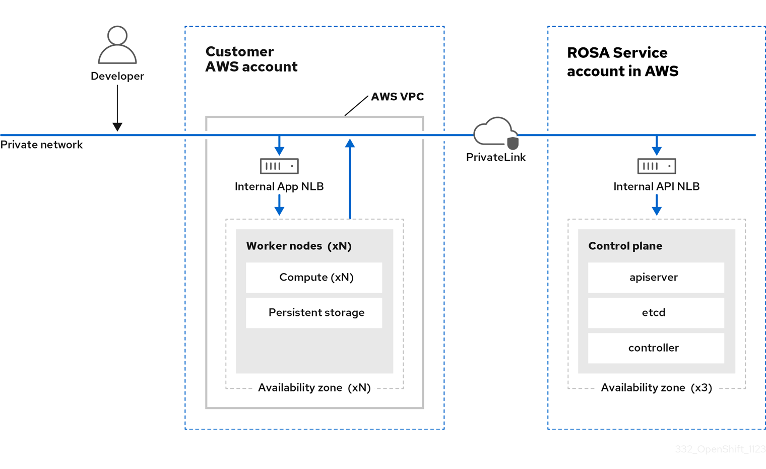
In Red Hat OpenShift Service on AWS (ROSA) with hosted control planes (HCP), the ROSA service hosts a highly-available, single-tenant OpenShift control plane. The hosted control plane is deployed across 3 availability zones with 2 API server instances and 3 etcd instances.
You can create a ROSA with HCP cluster with or without an internet-facing API server, with the latter considered a “private” cluster and the former considered a “public” cluster. Private API servers are only accessible from your VPC subnets. You access the hosted control plane through an AWS PrivateLink endpoint regardless of API privacy.
The worker nodes are deployed in your AWS account and run on your VPC private subnets. You can add additional private subnets from one or more availability zones to ensure high availability. Worker nodes are shared by OpenShift components and applications. OpenShift components such as the ingress controller, image registry, and monitoring are deployed on the worker nodes hosted on your VPC.
Figure 3.1. ROSA with HCP architecture
3.2.1. ROSA with HCP architecture on public and private networks
With ROSA with HCP, you can create your clusters on public or private networks. The following images depict the architecture of both public and private networks.
Figure 3.2. ROSA with HCP deployed on a public network
Figure 3.3. ROSA with HCP deployed on a private network
3.3. ROSA Classic architecture
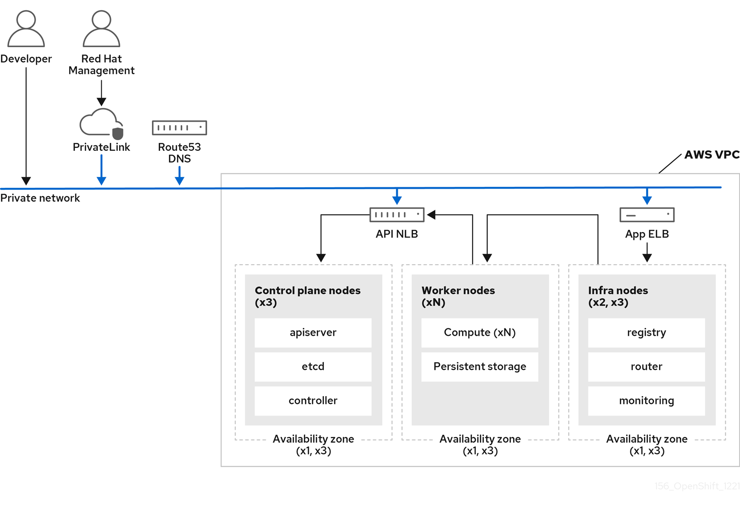
In Red Hat OpenShift Service on AWS (ROSA) Classic, both the control plane and the worker nodes are deployed in your VPC subnets.
3.3.1. ROSA Classic architecture on public and private networks
With ROSA Classic, you can create clusters that are accessible over public or private networks.
You can customize access patterns for your API server endpoint and Red Hat SRE management in the following ways:
- Public - API server endpoint and application routes are internet-facing.
- Private - API server endpoint and application routes are private. Private ROSA Classic clusters use some public subnets, but no control plane or worker nodes are deployed in public subnets.
- Private with AWS PrivateLink - API server endpoint and application routes are private. Public subnets or NAT gateways are not required in your VPC for egress. ROSA SRE management uses AWS PrivateLink.
The following image depicts the architecture of a ROSA Classic cluster deployed on both public and private networks.
Figure 3.4. ROSA Classic deployed on public and private networks
ROSA Classic clusters include infrastructure nodes where OpenShift components such as the ingress controller, image registry, and monitoring are deployed. The infrastructure nodes and the OpenShift components deployed on them are managed by ROSA Service SREs.
The following types of clusters are available with ROSA Classic:
- Single zone cluster - The control plane and worker nodes are hosted on a single availability zone.
- Multi-zone cluster - The control plane is hosted on three availability zones with an option to run worker nodes on one or three availability zones.
3.3.2. AWS PrivateLink architecture
The Red Hat managed infrastructure that creates AWS PrivateLink clusters is hosted on private subnets. The connection between Red Hat and the customer-provided infrastructure is created through AWS PrivateLink VPC endpoints.
AWS PrivateLink is supported on existing VPCs only.
The following diagram shows network connectivity of a PrivateLink cluster.
Figure 3.5. Multi-AZ AWS PrivateLink cluster deployed on private subnets
3.3.2.1. AWS reference architectures
AWS provides multiple reference architectures that can be useful to customers when planning how to set up a configuration that uses AWS PrivateLink. Here are three examples:
A public subnet connects directly to the internet through an internet gateway. A private subnet connects to the internet through a network address translation (NAT) gateway.
VPC with a private subnet and AWS Site-to-Site VPN access.
This configuration enables you to extend your network into the cloud without exposing your network to the internet.
To enable communication with your network over an Internet Protocol Security (IPsec) VPN tunnel, this configuration contains a virtual private cloud (VPC) with a single private subnet and a virtual private gateway. Communication over the internet does not use an internet gateway.
For more information, see VPC with a private subnet only and AWS Site-to-Site VPN access in the AWS documentation.
VPC with public and private subnets (NAT)
This configuration enables you to isolate your network so that the public subnet is reachable from the internet but the private subnet is not.
Only the public subnet can send outbound traffic directly to the internet. The private subnet can access the internet by using a network address translation (NAT) gateway that resides in the public subnet. This allows database servers to connect to the internet for software updates using the NAT gateway, but does not allow connections to be made directly from the internet to the database servers.
For more information, see VPC with public and private subnets (NAT) in the AWS documentation.
VPC with public and private subnets and AWS Site-to-Site VPN access
This configuration enables you to extend your network into the cloud and to directly access the internet from your VPC.
You can run a multi-tiered application with a scalable web front end in a public subnet, and house your data in a private subnet that is connected to your network by an IPsec AWS Site-to-Site VPN connection.
For more information, see VPC with public and private subnets and AWS Site-to-Site VPN access in the AWS documentation.
3.3.3. ROSA architecture with Local Zones
ROSA supports the use of AWS Local Zones, which are metropolis-centralized availability zones where customers can place latency-sensitive application workloads within a VPC. Local Zones are extensions of AWS Regions and are not enabled by default. When Local Zones are enabled and configured, the traffic is extended into the Local Zones for greater flexibility and lower latency. For more information, see "Configuring machine pools in Local Zones".
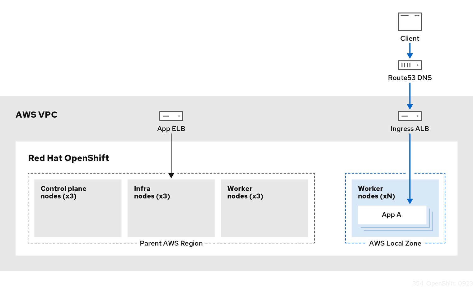
The following diagram displays a ROSA cluster without traffic routed into a Local Zone.
Figure 3.6. ROSA cluster without traffic routed into Local Zones
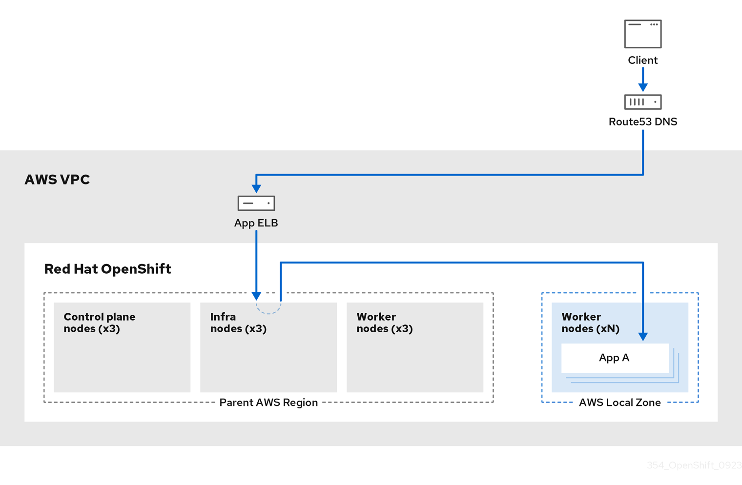
The following diagram displays a ROSA cluster with traffic routed into a Local Zone.
Figure 3.7. ROSA cluster with traffic routed into Local Zones
Additional resources


