Chapter 24. Multiple networks
24.1. Understanding multiple networks
In Kubernetes, container networking is delegated to networking plugins that implement the Container Network Interface (CNI).
OpenShift Container Platform uses the Multus CNI plugin to allow chaining of CNI plugins. During cluster installation, you configure your default pod network. The default network handles all ordinary network traffic for the cluster. You can define an additional network based on the available CNI plugins and attach one or more of these networks to your pods. You can define more than one additional network for your cluster, depending on your needs. This gives you flexibility when you configure pods that deliver network functionality, such as switching or routing.
24.1.1. Usage scenarios for an additional network
You can use an additional network in situations where network isolation is needed, including data plane and control plane separation. Isolating network traffic is useful for the following performance and security reasons:
- Performance
- You can send traffic on two different planes to manage how much traffic is along each plane.
- Security
- You can send sensitive traffic onto a network plane that is managed specifically for security considerations, and you can separate private data that must not be shared between tenants or customers.
All of the pods in the cluster still use the cluster-wide default network to maintain connectivity across the cluster. Every pod has an eth0 interface that is attached to the cluster-wide pod network. You can view the interfaces for a pod by using the oc exec -it <pod_name> -- ip a command. If you add additional network interfaces that use Multus CNI, they are named net1, net2, …, netN.
To attach additional network interfaces to a pod, you must create configurations that define how the interfaces are attached. You specify each interface by using a NetworkAttachmentDefinition custom resource (CR). A CNI configuration inside each of these CRs defines how that interface is created.
24.1.2. Additional networks in OpenShift Container Platform
OpenShift Container Platform provides the following CNI plugins for creating additional networks in your cluster:
- bridge: Configure a bridge-based additional network to allow pods on the same host to communicate with each other and the host.
- bond-cni: Configure a Bond CNI secondary network to provide a method for aggregating multiple network interfaces into a single logical bonded interface.
- host-device: Configure a host-device additional network to allow pods access to a physical Ethernet network device on the host system.
- ipvlan: Configure an ipvlan-based additional network to allow pods on a host to communicate with other hosts and pods on those hosts, similar to a macvlan-based additional network. Unlike a macvlan-based additional network, each pod shares the same MAC address as the parent physical network interface.
- vlan: Configure a vlan-based additional network to allow VLAN-based network isolation and connectivity for pods.
- macvlan: Configure a macvlan-based additional network to allow pods on a host to communicate with other hosts and pods on those hosts by using a physical network interface. Each pod that is attached to a macvlan-based additional network is provided a unique MAC address.
- tap: Configure a tap-based additional network to create a tap device inside the container namespace. A tap device enables user space programs to send and receive network packets.
- SR-IOV: Configure an SR-IOV based additional network to allow pods to attach to a virtual function (VF) interface on SR-IOV capable hardware on the host system.
-
route-override: Configure a
route-overridebased additional network to allow pods to override and set routes.
24.2. Configuring an additional network
As a cluster administrator, you can configure an additional network for your cluster. The following network types are supported:
24.2.1. Approaches to managing an additional network
You can manage the lifecycle of an additional network in OpenShift Container Platform by using one of two approaches: modifying the Cluster Network Operator (CNO) configuration or applying a YAML manifest. Each approach is mutually exclusive and you can only use one approach for managing an additional network at a time. For either approach, the additional network is managed by a Container Network Interface (CNI) plugin that you configure. The two different approaches are summarized here:
-
Modifying the Cluster Network Operator (CNO) configuration: Configuring additional networks through CNO is only possible for cluster administrators. The CNO automatically creates and manages the
NetworkAttachmentDefinitionobject. By using this approach, you can defineNetworkAttachmentDefinitionobjects at install time through configuration of theinstall-config. -
Applying a YAML manifest: You can manage the additional network directly by creating an
NetworkAttachmentDefinitionobject. Compared to modifying the CNO configuration, this approach gives you more granular control and flexibility when it comes to configuration.
When deploying OpenShift Container Platform nodes with multiple network interfaces on Red Hat OpenStack Platform (RHOSP) with OVN Kubernetes, DNS configuration of the secondary interface might take precedence over the DNS configuration of the primary interface. In this case, remove the DNS nameservers for the subnet ID that is attached to the secondary interface:
$ openstack subnet set --dns-nameserver 0.0.0.0 <subnet_id>24.2.2. IP address assignment for additional networks
For additional networks, IP addresses can be assigned using an IP Address Management (IPAM) CNI plugin, which supports various assignment methods, including Dynamic Host Configuration Protocol (DHCP) and static assignment.
The DHCP IPAM CNI plugin responsible for dynamic assignment of IP addresses operates with two distinct components:
- CNI Plugin: Responsible for integrating with the Kubernetes networking stack to request and release IP addresses.
- DHCP IPAM CNI Daemon: A listener for DHCP events that coordinates with existing DHCP servers in the environment to handle IP address assignment requests. This daemon is not a DHCP server itself.
For networks requiring type: dhcp in their IPAM configuration, ensure the following:
- A DHCP server is available and running in the environment. The DHCP server is external to the cluster and is expected to be part of the customer’s existing network infrastructure.
- The DHCP server is appropriately configured to serve IP addresses to the nodes.
In cases where a DHCP server is unavailable in the environment, it is recommended to use the Whereabouts IPAM CNI plugin instead. The Whereabouts CNI provides similar IP address management capabilities without the need for an external DHCP server.
Use the Whereabouts CNI plugin when there is no external DHCP server or where static IP address management is preferred. The Whereabouts plugin includes a reconciler daemon to manage stale IP address allocations.
A DHCP lease must be periodically renewed throughout the container’s lifetime, so a separate daemon, the DHCP IPAM CNI Daemon, is required. To deploy the DHCP IPAM CNI daemon, modify the Cluster Network Operator (CNO) configuration to trigger the deployment of this daemon as part of the additional network setup.
24.2.3. Configuration for an additional network attachment
An additional network is configured by using the NetworkAttachmentDefinition API in the k8s.cni.cncf.io API group.
Do not store any sensitive information or a secret in the NetworkAttachmentDefinition CRD because this information is accessible by the project administration user.
The configuration for the API is described in the following table:
| Field | Type | Description |
|---|---|---|
|
|
| The name for the additional network. |
|
|
| The namespace that the object is associated with. |
|
|
| The CNI plugin configuration in JSON format. |
24.2.3.1. Configuration of an additional network through the Cluster Network Operator
The configuration for an additional network attachment is specified as part of the Cluster Network Operator (CNO) configuration.
The following YAML describes the configuration parameters for managing an additional network with the CNO:
Cluster Network Operator configuration
apiVersion: operator.openshift.io/v1
kind: Network
metadata:
  name: cluster
spec:
  # ...
  additionalNetworks:
- name: <name>
namespace: <namespace>
rawCNIConfig: |-
      {
        ...
      }
type: Raw- 1
- An array of one or more additional network configurations.
- 2
- The name for the additional network attachment that you are creating. The name must be unique within the specified
namespace. - 3
- The namespace to create the network attachment in. If you do not specify a value then the
defaultnamespace is used.ImportantTo prevent namespace issues for the OVN-Kubernetes network plugin, do not name your additional network attachment
default, because this namespace is reserved for thedefaultadditional network attachment. - 4
- A CNI plugin configuration in JSON format.
24.2.3.2. Configuration of an additional network from a YAML manifest
The configuration for an additional network is specified from a YAML configuration file, such as in the following example:
apiVersion: k8s.cni.cncf.io/v1
kind: NetworkAttachmentDefinition
metadata:
  name: <name>
spec:
  config: |-
    {
      ...
}24.2.4. Configurations for additional network types
The specific configuration fields for additional networks is described in the following sections.
24.2.4.1. Configuration for a bridge additional network
The following object describes the configuration parameters for the bridge CNI plugin:
| Field | Type | Description |
|---|---|---|
|
|
|
The CNI specification version. The |
|
|
|
The value for the |
|
|
|
The name of the CNI plugin to configure: |
|
|
| The configuration object for the IPAM CNI plugin. The plugin manages IP address assignment for the attachment definition. |
|
|
|
Optional: Specify the name of the virtual bridge to use. If the bridge interface does not exist on the host, it is created. The default value is |
|
|
|
Optional: Set to |
|
|
|
Optional: Set to |
|
|
|
Optional: Set to |
|
|
|
Optional: Set to |
|
|
|
Optional: Set to |
|
|
|
Optional: Set to |
|
|
| Optional: Specify a virtual LAN (VLAN) tag as an integer value. By default, no VLAN tag is assigned. |
|
|
|
Optional: Indicates whether the default vlan must be preserved on the |
|
|
|
Optional: Assign a VLAN trunk tag. The default value is |
|
|
| Optional: Set the maximum transmission unit (MTU) to the specified value. The default value is automatically set by the kernel. |
|
|
|
Optional: Enables duplicate address detection for the container side |
|
|
|
Optional: Enables mac spoof check, limiting the traffic originating from the container to the mac address of the interface. The default value is |
The VLAN parameter configures the VLAN tag on the host end of the veth and also enables the vlan_filtering feature on the bridge interface.
To configure uplink for a L2 network you need to allow the vlan on the uplink interface by using the following command:
$ bridge vlan add vid VLAN_ID dev DEV24.2.4.1.1. bridge configuration example
The following example configures an additional network named bridge-net:
{
  "cniVersion": "0.3.1",
  "name": "bridge-net",
  "type": "bridge",
  "isGateway": true,
  "vlan": 2,
  "ipam": {
    "type": "dhcp"
    }
}
24.2.4.2. Configuration for a host device additional network
Specify your network device by setting only one of the following parameters: device,hwaddr, kernelpath, or pciBusID.
The following object describes the configuration parameters for the host-device CNI plugin:
| Field | Type | Description |
|---|---|---|
|
|
|
The CNI specification version. The |
|
|
|
The value for the |
|
|
|
The name of the CNI plugin to configure: |
|
|
|
Optional: The name of the device, such as |
|
|
| Optional: The device hardware MAC address. |
|
|
|
Optional: The Linux kernel device path, such as |
|
|
|
Optional: The PCI address of the network device, such as |
24.2.4.2.1. host-device configuration example
The following example configures an additional network named hostdev-net:
{
  "cniVersion": "0.3.1",
  "name": "hostdev-net",
  "type": "host-device",
  "device": "eth1"
}
24.2.4.3. Configuration for a Bond CNI secondary network
The Bond Container Network Interface (Bond CNI) enables the aggregation of multiple network interfaces into a single logical "bonded" interface within a container, enhancing network redundancy and fault tolerance. Only SR-IOV Virtual Functions (VFs) are supported for bonding with this plugin.
The following table describes the configuration parameters for the Bond CNI plugin:
| Field | Type | Description |
|---|---|---|
|
|
| Specifies the name given to this CNI network attachment definition. This name is used to identify and reference the interface within the container. |
|
|
| The CNI specification version. |
|
|
|
Specifies the name of the CNI plugin to configure: |
|
|
| Specifies the address resolution protocol (ARP) link monitoring frequency in milliseconds. This parameter defines how often the bond interface sends ARP requests to check the availability of its aggregated interfaces. |
|
|
| Optional: Specifies the maximum transmission unit (MTU) of the bond. The default is 1500. |
|
|
|
Optional: Specifies the |
|
|
| Specifies the bonding policy. |
|
|
|
Optional: Specifies whether the network interfaces intended for bonding are expected to be created and available directly within the container’s network namespace when the bond starts. If |
|
|
| Specifies the interfaces to be bonded. |
|
|
| The configuration object for the IPAM CNI plugin. The plugin manages IP address assignment for the attachment definition. |
24.2.4.3.1. Bond CNI plugin configuration example
The following example configures a secondary network named bond-net1:
{
 "type": "bond",
 "cniVersion": "0.3.1",
 "name": "bond-net1",
 "mode": "active-backup",
 "failOverMac": 1,
 "linksInContainer": true,
 "miimon": "100",
 "mtu": 1500,
 "links": [
       {"name": "net1"},
       {"name": "net2"}
   ],
  "ipam": {
        "type": "host-local",
        "subnet": "10.56.217.0/24",
        "routes": [{
        "dst": "0.0.0.0/0"
        }],
        "gateway": "10.56.217.1"
    }
}24.2.4.4. Configuration for a VLAN additional network
The following object describes the configuration parameters for the VLAN, vlan, CNI plugin:
| Field | Type | Description |
|---|---|---|
|
|
|
The CNI specification version. The |
|
|
|
The value for the |
|
|
|
The name of the CNI plugin to configure: |
|
|
|
The Ethernet interface to associate with the network attachment. If a |
|
|
|
Set the ID of the |
|
|
| The configuration object for the IPAM CNI plugin. The plugin manages IP address assignment for the attachment definition. |
|
|
| Optional: Set the maximum transmission unit (MTU) to the specified value. The default value is automatically set by the kernel. |
|
|
| Optional: DNS information to return. For example, a priority-ordered list of DNS nameservers. |
|
|
|
Optional: Specifies whether the |
A NetworkAttachmentDefinition custom resource definition (CRD) with a vlan configuration can be used only on a single pod in a node because the CNI plugin cannot create multiple vlan subinterfaces with the same vlanId on the same master interface.
24.2.4.4.1. VLAN configuration example
The following example demonstrates a vlan configuration with an additional network that is named vlan-net:
{
  "name": "vlan-net",
  "cniVersion": "0.3.1",
  "type": "vlan",
  "master": "eth0",
  "mtu": 1500,
  "vlanId": 5,
  "linkInContainer": false,
  "ipam": {
      "type": "host-local",
      "subnet": "10.1.1.0/24"
  },
  "dns": {
      "nameservers": [ "10.1.1.1", "8.8.8.8" ]
  }
}
24.2.4.5. Configuration for an IPVLAN additional network
The following object describes the configuration parameters for the IPVLAN, ipvlan, CNI plugin:
| Field | Type | Description |
|---|---|---|
|
|
|
The CNI specification version. The |
|
|
|
The value for the |
|
|
|
The name of the CNI plugin to configure: |
|
|
| The configuration object for the IPAM CNI plugin. The plugin manages IP address assignment for the attachment definition. This is required unless the plugin is chained. |
|
|
|
Optional: The operating mode for the virtual network. The value must be |
|
|
|
Optional: The Ethernet interface to associate with the network attachment. If a |
|
|
| Optional: Set the maximum transmission unit (MTU) to the specified value. The default value is automatically set by the kernel. |
|
|
|
Optional: Specifies whether the |
-
The
ipvlanobject does not allow virtual interfaces to communicate with themasterinterface. Therefore the container will not be able to reach the host by using theipvlaninterface. Be sure that the container joins a network that provides connectivity to the host, such as a network supporting the Precision Time Protocol (PTP). -
A single
masterinterface cannot simultaneously be configured to use bothmacvlanandipvlan. -
For IP allocation schemes that cannot be interface agnostic, the
ipvlanplugin can be chained with an earlier plugin that handles this logic. If themasteris omitted, then the previous result must contain a single interface name for theipvlanplugin to enslave. Ifipamis omitted, then the previous result is used to configure theipvlaninterface.
24.2.4.5.1. ipvlan configuration example
The following example configures an additional network named ipvlan-net:
{
  "cniVersion": "0.3.1",
  "name": "ipvlan-net",
  "type": "ipvlan",
  "master": "eth1",
  "linkInContainer": false,
  "mode": "l3",
  "ipam": {
    "type": "static",
    "addresses": [
       {
         "address": "192.168.10.10/24"
       }
    ]
  }
}
24.2.4.6. Configuration for a MACVLAN additional network
The following object describes the configuration parameters for the MAC Virtual LAN (MACVLAN) Container Network Interface (CNI) plugin:
| Field | Type | Description |
|---|---|---|
|
|
|
The CNI specification version. The |
|
|
|
The value for the |
|
|
|
The name of the CNI plugin to configure: |
|
|
| The configuration object for the IPAM CNI plugin. The plugin manages IP address assignment for the attachment definition. |
|
|
|
Optional: Configures traffic visibility on the virtual network. Must be either |
|
|
| Optional: The host network interface to associate with the newly created macvlan interface. If a value is not specified, then the default route interface is used. |
|
|
| Optional: The maximum transmission unit (MTU) to the specified value. The default value is automatically set by the kernel. |
|
|
|
Optional: Specifies whether the |
If you specify the master key for the plugin configuration, use a different physical network interface than the one that is associated with your primary network plugin to avoid possible conflicts.
24.2.4.6.1. MACVLAN configuration example
The following example configures an additional network named macvlan-net:
{
  "cniVersion": "0.3.1",
  "name": "macvlan-net",
  "type": "macvlan",
  "master": "eth1",
  "linkInContainer": false,
  "mode": "bridge",
  "ipam": {
    "type": "dhcp"
    }
}
24.2.4.7. Configuration for a TAP additional network
The following object describes the configuration parameters for the TAP CNI plugin:
| Field | Type | Description |
|---|---|---|
|
|
|
The CNI specification version. The |
|
|
|
The value for the |
|
|
|
The name of the CNI plugin to configure: |
|
|
| Optional: Request the specified MAC address for the interface. |
|
|
| Optional: Set the maximum transmission unit (MTU) to the specified value. The default value is automatically set by the kernel. |
|
|
| Optional: The SELinux context to associate with the tap device. Note
The value |
|
|
|
Optional: Set to |
|
|
| Optional: The user owning the tap device. |
|
|
| Optional: The group owning the tap device. |
|
|
| Optional: Set the tap device as a port of an already existing bridge. |
24.2.4.7.1. Tap configuration example
The following example configures an additional network named mynet:
{
 "name": "mynet",
 "cniVersion": "0.3.1",
 "type": "tap",
 "mac": "00:11:22:33:44:55",
 "mtu": 1500,
 "selinuxcontext": "system_u:system_r:container_t:s0",
 "multiQueue": true,
 "owner": 0,
 "group": 0
 "bridge": "br1"
}
24.2.4.7.2. Setting SELinux boolean for the TAP CNI plugin
To create the tap device with the container_t SELinux context, enable the container_use_devices boolean on the host by using the Machine Config Operator (MCO).
Prerequisites
-
You have installed the OpenShift CLI (
oc).
Procedure
Create a new YAML file named, such as
setsebool-container-use-devices.yaml, with the following details:apiVersion: machineconfiguration.openshift.io/v1 kind: MachineConfig metadata: labels: machineconfiguration.openshift.io/role: worker name: 99-worker-setsebool spec: config: ignition: version: 3.2.0 systemd: units: - enabled: true name: setsebool.service contents: | [Unit] Description=Set SELinux boolean for the TAP CNI plugin Before=kubelet.service [Service] Type=oneshot ExecStart=/usr/sbin/setsebool container_use_devices=on RemainAfterExit=true [Install] WantedBy=multi-user.target graphical.targetCreate the new
MachineConfigobject by running the following command:$ oc apply -f setsebool-container-use-devices.yamlNoteApplying any changes to the
MachineConfigobject causes all affected nodes to gracefully reboot after the change is applied. This update can take some time to be applied.Verify the change is applied by running the following command:
$ oc get machineconfigpoolsExpected output
NAME CONFIG UPDATED UPDATING DEGRADED MACHINECOUNT READYMACHINECOUNT UPDATEDMACHINECOUNT DEGRADEDMACHINECOUNT AGE master rendered-master-e5e0c8e8be9194e7c5a882e047379cfa True False False 3 3 3 0 7d2h worker rendered-worker-d6c9ca107fba6cd76cdcbfcedcafa0f2 True False False 3 3 3 0 7dNoteAll nodes should be in the updated and ready state.
24.2.4.8. Configuring routes using the route-override plugin on an additional network
The following object describes the configuration parameters for the route-override CNI plugin:
| Field | Type | Description |
|---|---|---|
|
|
|
The name of the CNI plugin to configure: |
|
|
|
Optional: Set to |
|
|
|
Optional: Set to |
|
|
| Optional: Specify the list of routes to delete from the container namespace. |
|
|
|
Optional: Specify the list of routes to add to the container namespace. Each route is a dictionary with |
|
|
|
Optional: Set this to |
24.2.4.8.1. Route-override plugin configuration example
The route-override CNI is a type of CNI that it is designed to be used when chained with a parent CNI. It does not operate independently, but relies on the parent CNI to first create the network interface and assign IP addresses before it can modify the routing rules.
The following example configures an additional network named mymacvlan. The parent CNI creates a network interface attached to eth1 and assigns an IP address in the 192.168.1.0/24 range using host-local IPAM. The route-override CNI is then chained to the parent CNI and modifies the routing rules by flushing existing routes, deleting the route to 192.168.0.0/24, and adding a new route for 192.168.0.0/24 with a custom gateway.
{
    "cniVersion": "0.3.0",
    "name": "mymacvlan",
    "plugins": [
        {
            "type": "macvlan",
            "master": "eth1",
            "mode": "bridge",
            "ipam": {
                "type": "host-local",
                "subnet": "192.168.1.0/24"
            }
        },
        {
            "type": "route-override",
            "flushroutes": true,
            "delroutes": [
                {
                    "dst": "192.168.0.0/24"
                }
            ],
            "addroutes": [
                {
                    "dst": "192.168.0.0/24",
                    "gw": "10.1.254.254"
                }
            ]
        }
    ]
}24.2.4.9. Configuration for an OVN-Kubernetes additional network
The Red Hat OpenShift Networking OVN-Kubernetes network plugin allows the configuration of secondary network interfaces for pods. To configure secondary network interfaces, you must define the configurations in the NetworkAttachmentDefinition custom resource definition (CRD).
Pod and multi-network policy creation might remain in a pending state until the OVN-Kubernetes control plane agent in the nodes processes the associated network-attachment-definition CRD.
You can configure an OVN-Kubernetes additional network in either layer 2 or localnet topologies.
- A layer 2 topology supports east-west cluster traffic, but does not allow access to the underlying physical network.
- A localnet topology allows connections to the physical network, but requires additional configuration of the underlying Open vSwitch (OVS) bridge on cluster nodes.
The following sections provide example configurations for each of the topologies that OVN-Kubernetes currently allows for secondary networks.
Networks names must be unique. For example, creating multiple NetworkAttachmentDefinition CRDs with different configurations that reference the same network is unsupported.
24.2.4.9.1. Supported platforms for OVN-Kubernetes additional network
You can use an OVN-Kubernetes additional network with the following supported platforms:
- Bare metal
- IBM Power®
- IBM Z®
- IBM® LinuxONE
- VMware vSphere
- Red Hat OpenStack Platform (RHOSP)
24.2.4.9.2. OVN-Kubernetes network plugin JSON configuration table
The following table describes the configuration parameters for the OVN-Kubernetes CNI network plugin:
| Field | Type | Description |
|---|---|---|
|
|
|
The CNI specification version. The required value is |
|
|
|
The name of the network. These networks are not namespaced. For example, a network named |
|
|
|
The name of the CNI plugin to configure. This value must be set to |
|
|
|
The topological configuration for the network. Must be one of |
|
|
| The subnet to use for the network across the cluster.
For When omitted, the logical switch implementing the network only provides layer 2 communication, and users must configure IP addresses for the pods. Port security only prevents MAC spoofing. |
|
|
| The maximum transmission unit (MTU). If you do not set a value, the Cluster Network Operator (CNO) sets a default MTU value by calculating the difference among the underlay MTU of the primary network interface, the overlay MTU of the pod network, such as the Geneve (Generic Network Virtualization Encapsulation), and byte capacity of any enabled features, such as IPsec. |
|
|
|
The metadata |
|
|
| A comma-separated list of CIDRs and IP addresses. IP addresses are removed from the assignable IP address pool and are never passed to the pods. |
|
|
|
If topology is set to |
24.2.4.9.3. Compatibility with multi-network policy
The multi-network policy API, which is provided by the MultiNetworkPolicy custom resource definition (CRD) in the k8s.cni.cncf.io API group, is compatible with an OVN-Kubernetes secondary network. When defining a network policy, the network policy rules that can be used depend on whether the OVN-Kubernetes secondary network defines the subnets field. Refer to the following table for details:
subnets field specified | Allowed multi-network policy selectors |
|---|---|
| Yes |
|
| No |
|
You can use the k8s.v1.cni.cncf.io/policy-for annotation on a MultiNetworkPolicy object to point to a NetworkAttachmentDefinition (NAD) custom resource (CR). The NAD CR defines the network to which the policy applies. The following example multi-network policy is valid only if the subnets field is defined in the secondary network CNI configuration for the secondary network named blue2:
Example multi-network policy that uses a pod selector
apiVersion: k8s.cni.cncf.io/v1beta1
kind: MultiNetworkPolicy
metadata:
  name: allow-same-namespace
  annotations:
    k8s.v1.cni.cncf.io/policy-for: blue2
spec:
  podSelector:
  ingress:
  - from:
    - podSelector: {}
The following example uses the ipBlock network policy selector, which is always valid for an OVN-Kubernetes additional network:
Example multi-network policy that uses an IP block selector
apiVersion: k8s.cni.cncf.io/v1beta1
kind: MultiNetworkPolicy
metadata:
  name:  ingress-ipblock
  annotations:
    k8s.v1.cni.cncf.io/policy-for: default/flatl2net
spec:
  podSelector:
    matchLabels:
      name: access-control
  policyTypes:
  - Ingress
  ingress:
  - from:
    - ipBlock:
        cidr: 10.200.0.0/30
24.2.4.9.4. Configuration for a layer 2 switched topology
The switched (layer 2) topology networks interconnect the workloads through a cluster-wide logical switch. This configuration can be used for IPv6 and dual-stack deployments.
Layer 2 switched topology networks only allow for the transfer of data packets between pods within a cluster.
The following JSON example configures a switched secondary network:
{
  "cniVersion": "0.3.1",
  "name": "l2-network",
  "type": "ovn-k8s-cni-overlay",
  "topology":"layer2",
  "subnets": "10.100.200.0/24",
  "mtu": 1300,
  "netAttachDefName": "ns1/l2-network",
  "excludeSubnets": "10.100.200.0/29"
}
24.2.4.9.5. Configuration for a localnet topology
The switched localnet topology interconnects the workloads created as Network Attachment Definitions (NADs) through a cluster-wide logical switch to a physical network.
24.2.4.9.5.1. Prerequisites for configuring OVN-Kubernetes additional network
- The NMState Operator is installed. For more information, see About the Kubernetes NMState Operator.
24.2.4.9.5.2. Configuration for an OVN-Kubernetes additional network mapping
You must map an additional network to the OVN bridge to use it as an OVN-Kubernetes additional network. Bridge mappings allow network traffic to reach the physical network. A bridge mapping associates a physical network name, also known as an interface label, to a bridge created with Open vSwitch (OVS).
You can create an NodeNetworkConfigurationPolicy (NNCP) object, part of the nmstate.io/v1 API group, to declaratively create the mapping. This API is provided by the NMState Operator. By using this API you can apply the bridge mapping to nodes that match your specified nodeSelector expression, such as node-role.kubernetes.io/worker: ''. With this declarative approach, the NMState Operator applies additional network configuration to all nodes specified by the node selector automatically and transparently.
When attaching an additional network, you can either use the existing br-ex bridge or create a new bridge. Which approach to use depends on your specific network infrastructure. Consider the following approaches:
-
If your nodes include only a single network interface, you must use the existing bridge. This network interface is owned and managed by OVN-Kubernetes and you must not remove it from the
br-exbridge or alter the interface configuration. If you remove or alter the network interface, your cluster network will stop working correctly. - If your nodes include several network interfaces, you can attach a different network interface to a new bridge, and use that for your additional network. This approach provides for traffic isolation from your primary cluster network.
The localnet1 network is mapped to the br-ex bridge in the following example:
Example mapping for sharing a bridge
apiVersion: nmstate.io/v1
kind: NodeNetworkConfigurationPolicy
metadata:
  name: mapping
spec:
  nodeSelector:
    node-role.kubernetes.io/worker: ''
  desiredState:
    ovn:
      bridge-mappings:
      - localnet: localnet1
bridge: br-ex
state: present - 1 1
- The name for the configuration object.
- 2
- A node selector that specifies the nodes to apply the node network configuration policy to.
- 3
- The name for the additional network from which traffic is forwarded to the OVS bridge. This additional network must match the name of the
spec.config.namefield of theNetworkAttachmentDefinitionCRD that defines the OVN-Kubernetes additional network. - 4
- The name of the OVS bridge on the node. This value is required only if you specify
state: present. - 5
- The state for the mapping. Must be either
presentto add the bridge orabsentto remove the bridge. The default value ispresent.The following JSON example configures a localnet secondary network that is named
localnet1. Note that the value for themtuparameter must match the MTU value that was set for the secondary network interface that is mapped to thebr-exbridge interface.{ "cniVersion": "0.3.1", "name": "localnet1", "type": "ovn-k8s-cni-overlay", "topology":"localnet", "physicalNetworkName": "localnet1", "subnets": "202.10.130.112/28", "vlanID": 33, "mtu": 1500, "netAttachDefName": "ns1/localnet-network", "excludeSubnets": "10.100.200.0/29" }
In the following example, the localnet2 network interface is attached to the ovs-br1 bridge. Through this attachment, the network interface is available to the OVN-Kubernetes network plugin as an additional network.
Example mapping for nodes with multiple interfaces
apiVersion: nmstate.io/v1
kind: NodeNetworkConfigurationPolicy
metadata:
  name: ovs-br1-multiple-networks
spec:
  nodeSelector:
    node-role.kubernetes.io/worker: ''
  desiredState:
    interfaces:
    - name: ovs-br1
      description: |-
        A dedicated OVS bridge with eth1 as a port
        allowing all VLANs and untagged traffic
      type: ovs-bridge
      state: up
      bridge:
        allow-extra-patch-ports: true
        options:
          stp: false
        port:
        - name: eth1
    ovn:
      bridge-mappings:
      - localnet: localnet2
bridge: ovs-br1
state: present - 1
- The name for the configuration object.
- 2
- A node selector that specifies the nodes to apply the node network configuration policy to.
- 3
- A new OVS bridge, separate from the default bridge used by OVN-Kubernetes for all cluster traffic.
- 4
- A network device on the host system to associate with this new OVS bridge.
- 5
- The name for the additional network from which traffic is forwarded to the OVS bridge. This additional network must match the name of the
spec.config.namefield of theNetworkAttachmentDefinitionCRD that defines the OVN-Kubernetes additional network. - 6
- The name of the OVS bridge on the node. This value is required only if you specify
state: present. - 7
- The state for the mapping. Must be either
presentto add the bridge orabsentto remove the bridge. The default value ispresent.The following JSON example configures a localnet secondary network that is named
localnet2. Note that the value for themtuparameter must match the MTU value that was set for theeth1secondary network interface.{ "cniVersion": "0.3.1", "name": "localnet2", "type": "ovn-k8s-cni-overlay", "topology":"localnet", "physicalNetworkName": "localnet2", "subnets": "202.10.130.112/28", "vlanID": 33, "mtu": 1500, "netAttachDefName": "ns1/localnet-network" "excludeSubnets": "10.100.200.0/29" }
24.2.4.9.6. Configuring pods for additional networks
You must specify the secondary network attachments through the k8s.v1.cni.cncf.io/networks annotation.
The following example provisions a pod with two secondary attachments, one for each of the attachment configurations presented in this guide.
apiVersion: v1
kind: Pod
metadata:
  annotations:
    k8s.v1.cni.cncf.io/networks: l2-network
  name: tinypod
  namespace: ns1
spec:
  containers:
  - args:
    - pause
    image: k8s.gcr.io/e2e-test-images/agnhost:2.36
    imagePullPolicy: IfNotPresent
    name: agnhost-container
24.2.4.9.7. Configuring pods with a static IP address
The following example provisions a pod with a static IP address.
- You can only specify the IP address for a pod’s secondary network attachment for layer 2 attachments.
- Specifying a static IP address for the pod is only possible when the attachment configuration does not feature subnets.
apiVersion: v1
kind: Pod
metadata:
  annotations:
    k8s.v1.cni.cncf.io/networks: '[
      {
        "name": "l2-network",
"mac": "02:03:04:05:06:07",
"interface": "myiface1",
        "ips": [
          "192.0.2.20/24"
          ]
      }
    ]'
  name: tinypod
  namespace: ns1
spec:
  containers:
  - args:
    - pause
    image: k8s.gcr.io/e2e-test-images/agnhost:2.36
    imagePullPolicy: IfNotPresent
name: agnhost-container24.2.5. Configuration of IP address assignment for an additional network
The IP address management (IPAM) Container Network Interface (CNI) plugin provides IP addresses for other CNI plugins.
You can use the following IP address assignment types:
- Static assignment.
- Dynamic assignment through a DHCP server. The DHCP server you specify must be reachable from the additional network.
- Dynamic assignment through the Whereabouts IPAM CNI plugin.
24.2.5.1. Static IP address assignment configuration
The following table describes the configuration for static IP address assignment:
| Field | Type | Description |
|---|---|---|
|
|
|
The IPAM address type. The value |
|
|
| An array of objects specifying IP addresses to assign to the virtual interface. Both IPv4 and IPv6 IP addresses are supported. |
|
|
| An array of objects specifying routes to configure inside the pod. |
|
|
| Optional: An array of objects specifying the DNS configuration. |
The addresses array requires objects with the following fields:
| Field | Type | Description |
|---|---|---|
|
|
|
An IP address and network prefix that you specify. For example, if you specify |
|
|
| The default gateway to route egress network traffic to. |
| Field | Type | Description |
|---|---|---|
|
|
|
The IP address range in CIDR format, such as |
|
|
| The gateway where network traffic is routed. |
| Field | Type | Description |
|---|---|---|
|
|
| An array of one or more IP addresses for to send DNS queries to. |
|
|
|
The default domain to append to a hostname. For example, if the domain is set to |
|
|
|
An array of domain names to append to an unqualified hostname, such as |
Static IP address assignment configuration example
{
  "ipam": {
    "type": "static",
      "addresses": [
        {
          "address": "191.168.1.7/24"
        }
      ]
  }
}
24.2.5.2. Dynamic IP address (DHCP) assignment configuration
The following JSON describes the configuration for dynamic IP address address assignment with DHCP.
A pod obtains its original DHCP lease when it is created. The lease must be periodically renewed by a minimal DHCP server deployment running on the cluster.
To trigger the deployment of the DHCP server, you must create a shim network attachment by editing the Cluster Network Operator configuration, as in the following example:
Example shim network attachment definition
apiVersion: operator.openshift.io/v1
kind: Network
metadata:
  name: cluster
spec:
  additionalNetworks:
  - name: dhcp-shim
    namespace: default
    type: Raw
    rawCNIConfig: |-
      {
        "name": "dhcp-shim",
        "cniVersion": "0.3.1",
        "type": "bridge",
        "ipam": {
          "type": "dhcp"
        }
      }
# ...| Field | Type | Description |
|---|---|---|
|
|
|
The IPAM address type. The value |
Dynamic IP address (DHCP) assignment configuration example
{
  "ipam": {
    "type": "dhcp"
  }
}
24.2.5.3. Dynamic IP address assignment configuration with Whereabouts
The Whereabouts CNI plugin allows the dynamic assignment of an IP address to an additional network without the use of a DHCP server.
The following table describes the configuration for dynamic IP address assignment with Whereabouts:
| Field | Type | Description |
|---|---|---|
|
|
|
The IPAM address type. The value |
|
|
| An IP address and range in CIDR notation. IP addresses are assigned from within this range of addresses. |
|
|
| Optional: A list of zero or more IP addresses and ranges in CIDR notation. IP addresses within an excluded address range are not assigned. |
Dynamic IP address assignment configuration example that uses Whereabouts
{
  "ipam": {
    "type": "whereabouts",
    "range": "192.0.2.192/27",
    "exclude": [
       "192.0.2.192/30",
       "192.0.2.196/32"
    ]
  }
}
24.2.5.4. Creating a whereabouts-reconciler daemon set
The Whereabouts reconciler is responsible for managing dynamic IP address assignments for the pods within a cluster by using the Whereabouts IP Address Management (IPAM) solution. It ensures that each pod gets a unique IP address from the specified IP address range. It also handles IP address releases when pods are deleted or scaled down.
You can also use a NetworkAttachmentDefinition custom resource definition (CRD) for dynamic IP address assignment.
The whereabouts-reconciler daemon set is automatically created when you configure an additional network through the Cluster Network Operator. It is not automatically created when you configure an additional network from a YAML manifest.
To trigger the deployment of the whereabouts-reconciler daemon set, you must manually create a whereabouts-shim network attachment by editing the Cluster Network Operator custom resource (CR) file.
Use the following procedure to deploy the whereabouts-reconciler daemon set.
Procedure
Edit the
Network.operator.openshift.iocustom resource (CR) by running the following command:$ oc edit network.operator.openshift.io clusterInclude the
additionalNetworkssection shown in this example YAML extract within thespecdefinition of the custom resource (CR):apiVersion: operator.openshift.io/v1 kind: Network metadata: name: cluster # ... spec: additionalNetworks: - name: whereabouts-shim namespace: default rawCNIConfig: |- { "name": "whereabouts-shim", "cniVersion": "0.3.1", "type": "bridge", "ipam": { "type": "whereabouts" } } type: Raw # ...- Save the file and exit the text editor.
Verify that the
whereabouts-reconcilerdaemon set deployed successfully by running the following command:$ oc get all -n openshift-multus | grep whereabouts-reconcilerExample output
pod/whereabouts-reconciler-jnp6g 1/1 Running 0 6s
pod/whereabouts-reconciler-k76gg 1/1 Running 0 6s
pod/whereabouts-reconciler-k86t9 1/1 Running 0 6s
pod/whereabouts-reconciler-p4sxw 1/1 Running 0 6s
pod/whereabouts-reconciler-rvfdv 1/1 Running 0 6s
pod/whereabouts-reconciler-svzw9 1/1 Running 0 6s
daemonset.apps/whereabouts-reconciler 6 6 6 6 6 kubernetes.io/os=linux 6s
24.2.5.5. Configuring the Whereabouts IP reconciler schedule
The Whereabouts IPAM CNI plugin runs the IP reconciler daily. This process cleans up any stranded IP allocations that might result in exhausting IPs and therefore prevent new pods from getting an IP allocated to them.
Use this procedure to change the frequency at which the IP reconciler runs.
Prerequisites
-
You installed the OpenShift CLI (
oc). -
You have access to the cluster as a user with the
cluster-adminrole. -
You have deployed the
whereabouts-reconcilerdaemon set, and thewhereabouts-reconcilerpods are up and running.
Procedure
Run the following command to create a
ConfigMapobject namedwhereabouts-configin theopenshift-multusnamespace with a specific cron expression for the IP reconciler:$ oc create configmap whereabouts-config -n openshift-multus --from-literal=reconciler_cron_expression="*/15 * * * *"This cron expression indicates the IP reconciler runs every 15 minutes. Adjust the expression based on your specific requirements.
NoteThe
whereabouts-reconcilerdaemon set can only consume a cron expression pattern that includes five asterisks. The sixth, which is used to denote seconds, is currently not supported.Retrieve information about resources related to the
whereabouts-reconcilerdaemon set and pods within theopenshift-multusnamespace by running the following command:$ oc get all -n openshift-multus | grep whereabouts-reconcilerExample output
pod/whereabouts-reconciler-2p7hw                   1/1     Running   0             4m14s
pod/whereabouts-reconciler-76jk7                   1/1     Running   0             4m14s
pod/whereabouts-reconciler-94zw6                   1/1     Running   0             4m14s
pod/whereabouts-reconciler-mfh68                   1/1     Running   0             4m14s
pod/whereabouts-reconciler-pgshz                   1/1     Running   0             4m14s
pod/whereabouts-reconciler-xn5xz                   1/1     Running   0             4m14s
daemonset.apps/whereabouts-reconciler          6         6         6       6            6           kubernetes.io/os=linux   4m16s
Run the following command to verify that the
whereabouts-reconcilerpod runs the IP reconciler with the configured interval:$ oc -n openshift-multus logs whereabouts-reconciler-2p7hwExample output
2024-02-02T16:33:54Z [debug] event not relevant: "/cron-schedule/..2024_02_02_16_33_54.1375928161": CREATE
2024-02-02T16:33:54Z [debug] event not relevant: "/cron-schedule/..2024_02_02_16_33_54.1375928161": CHMOD
2024-02-02T16:33:54Z [debug] event not relevant: "/cron-schedule/..data_tmp": RENAME
2024-02-02T16:33:54Z [verbose] using expression: */15 * * * *
2024-02-02T16:33:54Z [verbose] configuration updated to file "/cron-schedule/..data". New cron expression: */15 * * * *
2024-02-02T16:33:54Z [verbose] successfully updated CRON configuration id "00c2d1c9-631d-403f-bb86-73ad104a6817" - new cron expression: */15 * * * *
2024-02-02T16:33:54Z [debug] event not relevant: "/cron-schedule/config": CREATE
2024-02-02T16:33:54Z [debug] event not relevant: "/cron-schedule/..2024_02_02_16_26_17.3874177937": REMOVE
2024-02-02T16:45:00Z [verbose] starting reconciler run
2024-02-02T16:45:00Z [debug] NewReconcileLooper - inferred connection data
2024-02-02T16:45:00Z [debug] listing IP pools
2024-02-02T16:45:00Z [debug] no IP addresses to cleanup
2024-02-02T16:45:00Z [verbose] reconciler success
24.2.5.6. Creating a configuration for assignment of dual-stack IP addresses dynamically
Dual-stack IP address assignment can be configured with the ipRanges parameter for:
- IPv4 addresses
- IPv6 addresses
- multiple IP address assignment
Procedure
-
Set
typetowhereabouts. Use
ipRangesto allocate IP addresses as shown in the following example:cniVersion: operator.openshift.io/v1 kind: Network =metadata: name: cluster spec: additionalNetworks: - name: whereabouts-shim namespace: default type: Raw rawCNIConfig: |- { "name": "whereabouts-dual-stack", "cniVersion": "0.3.1, "type": "bridge", "ipam": { "type": "whereabouts", "ipRanges": [ {"range": "192.168.10.0/24"}, {"range": "2001:db8::/64"} ] } }- Attach network to a pod. For more information, see "Adding a pod to an additional network".
- Verify that all IP addresses are assigned.
Run the following command to ensure the IP addresses are assigned as metadata.
$ oc exec -it mypod -- ip a
24.2.6. Creating an additional network attachment with the Cluster Network Operator
The Cluster Network Operator (CNO) manages additional network definitions. When you specify an additional network to create, the CNO creates the NetworkAttachmentDefinition CRD automatically.
Do not edit the NetworkAttachmentDefinition CRDs that the Cluster Network Operator manages. Doing so might disrupt network traffic on your additional network.
Prerequisites
-
Install the OpenShift CLI (
oc). -
Log in as a user with
cluster-adminprivileges.
Procedure
Optional: Create the namespace for the additional networks:
$ oc create namespace <namespace_name>To edit the CNO configuration, enter the following command:
$ oc edit networks.operator.openshift.io clusterModify the CR that you are creating by adding the configuration for the additional network that you are creating, as in the following example CR.
apiVersion: operator.openshift.io/v1 kind: Network metadata: name: cluster spec: # ... additionalNetworks: - name: tertiary-net namespace: namespace2 type: Raw rawCNIConfig: |- { "cniVersion": "0.3.1", "name": "tertiary-net", "type": "ipvlan", "master": "eth1", "mode": "l2", "ipam": { "type": "static", "addresses": [ { "address": "192.168.1.23/24" } ] } }- Save your changes and quit the text editor to commit your changes.
Verification
Confirm that the CNO created the
NetworkAttachmentDefinitionCRD by running the following command. There might be a delay before the CNO creates the CRD.$ oc get network-attachment-definitions -n <namespace>where:
<namespace>- Specifies the namespace for the network attachment that you added to the CNO configuration.
Example output
NAME                 AGE
test-network-1       14m
24.2.7. Creating an additional network attachment by applying a YAML manifest
Prerequisites
-
Install the OpenShift CLI (
oc). -
Log in as a user with
cluster-adminprivileges.
Procedure
Create a YAML file with your additional network configuration, such as in the following example:
apiVersion: k8s.cni.cncf.io/v1
kind: NetworkAttachmentDefinition
metadata:
  name: next-net
spec:
  config: |-
    {
      "cniVersion": "0.3.1",
      "name": "work-network",
      "type": "host-device",
      "device": "eth1",
      "ipam": {
        "type": "dhcp"
      }
    }
To create the additional network, enter the following command:
$ oc apply -f <file>.yamlwhere:
<file>- Specifies the name of the file contained the YAML manifest.
24.2.8. About configuring the master interface in the container network namespace
You can create a MAC-VLAN, an IP-VLAN, or a VLAN subinterface that is based on a master interface that exists in a container namespace. You can also create a master interface as part of the pod network configuration in a separate network attachment definition CRD.
To use a container namespace master interface, you must specify true for the linkInContainer parameter that exists in the subinterface configuration of the NetworkAttachmentDefinition CRD.
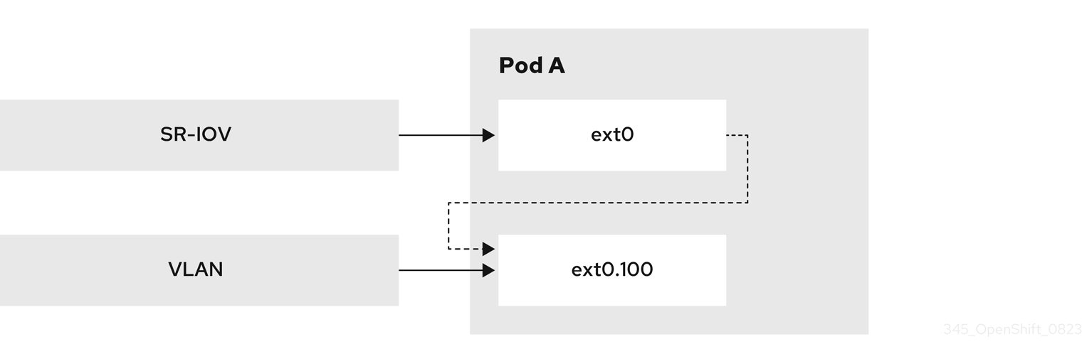
24.2.8.1. Creating multiple VLANs on SR-IOV VFs
An example use case for utilizing this feature is to create multiple VLANs based on SR-IOV VFs. To do so, begin by creating an SR-IOV network and then define the network attachments for the VLAN interfaces.
The following example shows how to configure the setup illustrated in this diagram.
Figure 24.1. Creating VLANs
Prerequisites
-
You installed the OpenShift CLI (
oc). -
You have access to the cluster as a user with the
cluster-adminrole. - You have installed the SR-IOV Network Operator.
Procedure
Create a dedicated container namespace where you want to deploy your pod by using the following command:
$ oc new-project test-namespaceCreate an SR-IOV node policy:
Create an
SriovNetworkNodePolicyobject, and then save the YAML in thesriov-node-network-policy.yamlfile:apiVersion: sriovnetwork.openshift.io/v1 kind: SriovNetworkNodePolicy metadata: name: sriovnic namespace: openshift-sriov-network-operator spec: deviceType: netdevice isRdma: false needVhostNet: true nicSelector: vendor: "15b3"1 deviceID: "101b"2 rootDevices: ["00:05.0"] numVfs: 10 priority: 99 resourceName: sriovnic nodeSelector: feature.node.kubernetes.io/network-sriov.capable: "true"NoteThe SR-IOV network node policy configuration example, with the setting
deviceType: netdevice, is tailored specifically for Mellanox Network Interface Cards (NICs).Apply the YAML by running the following command:
$ oc apply -f sriov-node-network-policy.yamlNoteApplying this might take some time due to the node requiring a reboot.
Create an SR-IOV network:
Create the
SriovNetworkcustom resource (CR) for the additional SR-IOV network attachment as in the following example CR. Save the YAML as the filesriov-network-attachment.yaml:apiVersion: sriovnetwork.openshift.io/v1 kind: SriovNetwork metadata: name: sriov-network namespace: openshift-sriov-network-operator spec: networkNamespace: test-namespace resourceName: sriovnic spoofChk: "off" trust: "on"Apply the YAML by running the following command:
$ oc apply -f sriov-network-attachment.yaml
Create the VLAN additional network:
Using the following YAML example, create a file named
vlan100-additional-network-configuration.yaml:apiVersion: k8s.cni.cncf.io/v1 kind: NetworkAttachmentDefinition metadata: name: vlan-100 namespace: test-namespace spec: config: | { "cniVersion": "0.4.0", "name": "vlan-100", "plugins": [ { "type": "vlan", "master": "ext0",1 "mtu": 1500, "vlanId": 100, "linkInContainer": true,2 "ipam": {"type": "whereabouts", "ipRanges": [{"range": "1.1.1.0/24"}]} } ] }Apply the YAML file by running the following command:
$ oc apply -f vlan100-additional-network-configuration.yaml
Create a pod definition by using the earlier specified networks:
Using the following YAML example, create a file named
pod-a.yamlfile:NoteThe manifest below includes 2 resources:
- Namespace with security labels
- Pod definition with appropriate network annotation
apiVersion: v1
kind: Namespace
metadata:
  name: test-namespace
  labels:
    pod-security.kubernetes.io/enforce: privileged
    pod-security.kubernetes.io/audit: privileged
    pod-security.kubernetes.io/warn: privileged
    security.openshift.io/scc.podSecurityLabelSync: "false"
---
apiVersion: v1
kind: Pod
metadata:
  name: nginx-pod
  namespace: test-namespace
  annotations:
    k8s.v1.cni.cncf.io/networks: '[
      {
        "name": "sriov-network",
        "namespace": "test-namespace",
        "interface": "ext0"
1 }, { "name": "vlan-100", "namespace": "test-namespace", "interface": "ext0.100" } ]' spec: securityContext: runAsNonRoot: true containers: - name: nginx-container image: nginxinc/nginx-unprivileged:latest securityContext: allowPrivilegeEscalation: false capabilities: drop: ["ALL"] ports: - containerPort: 80 seccompProfile: type: "RuntimeDefault"- 1
- The name to be used as the
masterfor the VLAN interface.
Apply the YAML file by running the following command:
$ oc apply -f pod-a.yaml
Get detailed information about the
nginx-podwithin thetest-namespaceby running the following command:$ oc describe pods nginx-pod -n test-namespaceExample output
Name:         nginx-pod
Namespace:    test-namespace
Priority:     0
Node:         worker-1/10.46.186.105
Start Time:   Mon, 14 Aug 2023 16:23:13 -0400
Labels:       <none>
Annotations:  k8s.ovn.org/pod-networks:
                {"default":{"ip_addresses":["10.131.0.26/23"],"mac_address":"0a:58:0a:83:00:1a","gateway_ips":["10.131.0.1"],"routes":[{"dest":"10.128.0.0...
              k8s.v1.cni.cncf.io/network-status:
                [{
                    "name": "ovn-kubernetes",
                    "interface": "eth0",
                    "ips": [
                        "10.131.0.26"
                    ],
                    "mac": "0a:58:0a:83:00:1a",
                    "default": true,
                    "dns": {}
                },{
                    "name": "test-namespace/sriov-network",
                    "interface": "ext0",
                    "mac": "6e:a7:5e:3f:49:1b",
                    "dns": {},
                    "device-info": {
                        "type": "pci",
                        "version": "1.0.0",
                        "pci": {
                            "pci-address": "0000:d8:00.2"
                        }
                    }
                },{
                    "name": "test-namespace/vlan-100",
                    "interface": "ext0.100",
                    "ips": [
                        "1.1.1.1"
                    ],
                    "mac": "6e:a7:5e:3f:49:1b",
                    "dns": {}
                }]
              k8s.v1.cni.cncf.io/networks:
                [ { "name": "sriov-network", "namespace": "test-namespace", "interface": "ext0" }, { "name": "vlan-100", "namespace": "test-namespace", "i...
              openshift.io/scc: privileged
Status:       Running
IP:           10.131.0.26
IPs:
  IP:  10.131.0.26
24.2.8.2. Creating a subinterface based on a bridge master interface in a container namespace
You can create a subinterface based on a bridge master interface that exists in a container namespace. Creating a subinterface can be applied to other types of interfaces.
Prerequisites
-
You have installed the OpenShift CLI (
oc). -
You are logged in to the OpenShift Container Platform cluster as a user with
cluster-adminprivileges.
Procedure
Create a dedicated container namespace where you want to deploy your pod by entering the following command:
$ oc new-project test-namespaceUsing the following YAML example, create a bridge
NetworkAttachmentDefinitioncustom resource definition (CRD) file namedbridge-nad.yaml:apiVersion: "k8s.cni.cncf.io/v1" kind: NetworkAttachmentDefinition metadata: name: bridge-network spec: config: '{ "cniVersion": "0.4.0", "name": "bridge-network", "type": "bridge", "bridge": "br-001", "isGateway": true, "ipMasq": true, "hairpinMode": true, "ipam": { "type": "host-local", "subnet": "10.0.0.0/24", "routes": [{"dst": "0.0.0.0/0"}] } }'Run the following command to apply the
NetworkAttachmentDefinitionCRD to your OpenShift Container Platform cluster:$ oc apply -f bridge-nad.yamlVerify that you successfully created a
NetworkAttachmentDefinitionCRD by entering the following command:$ oc get network-attachment-definitionsExample output
NAME             AGE
bridge-network   15s
Using the following YAML example, create a file named
ipvlan-additional-network-configuration.yamlfor the IPVLAN additional network configuration:apiVersion: k8s.cni.cncf.io/v1 kind: NetworkAttachmentDefinition metadata: name: ipvlan-net namespace: test-namespace spec: config: '{ "cniVersion": "0.3.1", "name": "ipvlan-net", "type": "ipvlan", "master": "ext0",1 "mode": "l3", "linkInContainer": true,2 "ipam": {"type": "whereabouts", "ipRanges": [{"range": "10.0.0.0/24"}]} }'Apply the YAML file by running the following command:
$ oc apply -f ipvlan-additional-network-configuration.yamlVerify that the
NetworkAttachmentDefinitionCRD has been created successfully by running the following command:$ oc get network-attachment-definitionsExample output
NAME             AGE
bridge-network   87s
ipvlan-net       9s
Using the following YAML example, create a file named
pod-a.yamlfor the pod definition:apiVersion: v1 kind: Pod metadata: name: pod-a namespace: test-namespace annotations: k8s.v1.cni.cncf.io/networks: '[ { "name": "bridge-network", "interface": "ext0"1 }, { "name": "ipvlan-net", "interface": "ext1" } ]' spec: securityContext: runAsNonRoot: true seccompProfile: type: RuntimeDefault containers: - name: test-pod image: quay.io/openshifttest/hello-sdn@sha256:c89445416459e7adea9a5a416b3365ed3d74f2491beb904d61dc8d1eb89a72a4 securityContext: allowPrivilegeEscalation: false capabilities: drop: [ALL]- 1
- Specifies the name to be used as the
masterfor the IPVLAN interface.
Apply the YAML file by running the following command:
$ oc apply -f pod-a.yamlVerify that the pod is running by using the following command:
$ oc get pod -n test-namespaceExample output
NAME    READY   STATUS    RESTARTS   AGE
pod-a   1/1     Running   0          2m36s
Show network interface information about the
pod-aresource within thetest-namespaceby running the following command:$ oc exec -n test-namespace pod-a -- ip aExample output
1: lo: <LOOPBACK,UP,LOWER_UP> mtu 65536 qdisc noqueue state UNKNOWN group default qlen 1000
    link/loopback 00:00:00:00:00:00 brd 00:00:00:00:00:00
    inet 127.0.0.1/8 scope host lo
       valid_lft forever preferred_lft forever
    inet6 ::1/128 scope host
       valid_lft forever preferred_lft forever
3: eth0@if105: <BROADCAST,MULTICAST,UP,LOWER_UP> mtu 1400 qdisc noqueue state UP group default
    link/ether 0a:58:0a:d9:00:5d brd ff:ff:ff:ff:ff:ff link-netnsid 0
    inet 10.217.0.93/23 brd 10.217.1.255 scope global eth0
       valid_lft forever preferred_lft forever
    inet6 fe80::488b:91ff:fe84:a94b/64 scope link
       valid_lft forever preferred_lft forever
4: ext0@if107: <BROADCAST,MULTICAST,UP,LOWER_UP> mtu 1500 qdisc noqueue state UP group default
    link/ether be:da:bd:7e:f4:37 brd ff:ff:ff:ff:ff:ff link-netnsid 0
    inet 10.0.0.2/24 brd 10.0.0.255 scope global ext0
       valid_lft forever preferred_lft forever
    inet6 fe80::bcda:bdff:fe7e:f437/64 scope link
       valid_lft forever preferred_lft forever
5: ext1@ext0: <BROADCAST,MULTICAST,NOARP,UP,LOWER_UP> mtu 1500 qdisc noqueue state UNKNOWN group default
    link/ether be:da:bd:7e:f4:37 brd ff:ff:ff:ff:ff:ff
    inet 10.0.0.1/24 brd 10.0.0.255 scope global ext1
       valid_lft forever preferred_lft forever
    inet6 fe80::beda:bd00:17e:f437/64 scope link
       valid_lft forever preferred_lft forever
This output shows that the network interface
ext1is associated with the physical interfaceext0.
24.3. About virtual routing and forwarding
24.3.1. About virtual routing and forwarding
Virtual routing and forwarding (VRF) devices combined with IP rules provide the ability to create virtual routing and forwarding domains. VRF reduces the number of permissions needed by CNF, and provides increased visibility of the network topology of secondary networks. VRF is used to provide multi-tenancy functionality, for example, where each tenant has its own unique routing tables and requires different default gateways.
Processes can bind a socket to the VRF device. Packets through the binded socket use the routing table associated with the VRF device. An important feature of VRF is that it impacts only OSI model layer 3 traffic and above so L2 tools, such as LLDP, are not affected. This allows higher priority IP rules such as policy based routing to take precedence over the VRF device rules directing specific traffic.
24.3.1.1. Benefits of secondary networks for pods for telecommunications operators
In telecommunications use cases, each CNF can potentially be connected to multiple different networks sharing the same address space. These secondary networks can potentially conflict with the cluster’s main network CIDR. Using the CNI VRF plugin, network functions can be connected to different customers' infrastructure using the same IP address, keeping different customers isolated. IP addresses are overlapped with OpenShift Container Platform IP space. The CNI VRF plugin also reduces the number of permissions needed by CNF and increases the visibility of network topologies of secondary networks.
24.4. Configuring multi-network policy
As a cluster administrator, you can configure a multi-network policy for a Single-Root I/O Virtualization (SR-IOV), MAC Virtual Local Area Network (MacVLAN), or OVN-Kubernetes additional networks. MacVLAN additional networks are fully supported. Other types of additional networks, such as IP Virtual Local Area Network (IPVLAN), are not supported.
Support for configuring multi-network policies for SR-IOV additional networks is only supported with kernel network interface controllers (NICs). SR-IOV is not supported for Data Plane Development Kit (DPDK) applications.
24.4.1. Differences between multi-network policy and network policy
Although the MultiNetworkPolicy API implements the NetworkPolicy API, there are several important differences:
You must use the
MultiNetworkPolicyAPI:apiVersion: k8s.cni.cncf.io/v1beta1 kind: MultiNetworkPolicy-
You must use the
multi-networkpolicyresource name when using the CLI to interact with multi-network policies. For example, you can view a multi-network policy object with theoc get multi-networkpolicy <name>command where<name>is the name of a multi-network policy. You can use the
k8s.v1.cni.cncf.io/policy-forannotation on aMultiNetworkPolicyobject to point to aNetworkAttachmentDefinition(NAD) custom resource (CR). The NAD CR defines the network to which the policy applies.Example multi-network policy that includes the
k8s.v1.cni.cncf.io/policy-forannotationapiVersion: k8s.cni.cncf.io/v1beta1 kind: MultiNetworkPolicy metadata: annotations: k8s.v1.cni.cncf.io/policy-for:<namespace_name>/<network_name>where:
<namespace_name>- Specifies the namespace name.
<network_name>- Specifies the name of a network attachment definition.
24.4.2. Enabling multi-network policy for the cluster
As a cluster administrator, you can enable multi-network policy support on your cluster.
Prerequisites
-
Install the OpenShift CLI (
oc). -
Log in to the cluster with a user with
cluster-adminprivileges.
Procedure
Create the
multinetwork-enable-patch.yamlfile with the following YAML:apiVersion: operator.openshift.io/v1 kind: Network metadata: name: cluster spec: useMultiNetworkPolicy: trueConfigure the cluster to enable multi-network policy:
$ oc patch network.operator.openshift.io cluster --type=merge --patch-file=multinetwork-enable-patch.yamlExample output
network.operator.openshift.io/cluster patched
24.4.3. Supporting multi-network policies in IPv6 networks
The ICMPv6 Neighbor Discovery Protocol (NDP) is a set of messages and processes that enable devices to discover and maintain information about neighboring nodes. NDP plays a crucial role in IPv6 networks, facilitating the interaction between devices on the same link.
The Cluster Network Operator (CNO) deploys the iptables implementation of multi-network policy when the useMultiNetworkPolicy parameter is set to true.
To support multi-network policies in IPv6 networks the Cluster Network Operator deploys the following set of rules in every pod affected by a multi-network policy:
Multi-network policy custom rules
kind: ConfigMap
apiVersion: v1
metadata:
name: multi-networkpolicy-custom-rules
namespace: openshift-multus
data:
custom-v6-rules.txt: |
# accept NDP
-p icmpv6 --icmpv6-type neighbor-solicitation -j ACCEPT
-p icmpv6 --icmpv6-type neighbor-advertisement -j ACCEPT
# accept RA/RS
-p icmpv6 --icmpv6-type router-solicitation -j ACCEPT
-p icmpv6 --icmpv6-type router-advertisement -j ACCEPT - 1
- This rule allows incoming ICMPv6 neighbor solicitation messages, which are part of the neighbor discovery protocol (NDP). These messages help determine the link-layer addresses of neighboring nodes.
- 2
- This rule allows incoming ICMPv6 neighbor advertisement messages, which are part of NDP and provide information about the link-layer address of the sender.
- 3
- This rule permits incoming ICMPv6 router solicitation messages. Hosts use these messages to request router configuration information.
- 4
- This rule allows incoming ICMPv6 router advertisement messages, which give configuration information to hosts.
You cannot edit these predefined rules.
These rules collectively enable essential ICMPv6 traffic for correct network functioning, including address resolution and router communication in an IPv6 environment. With these rules in place and a multi-network policy denying traffic, applications are not expected to experience connectivity issues.
24.4.4. Working with multi-network policy
As a cluster administrator, you can create, edit, view, and delete multi-network policies.
24.4.4.1. Prerequisites
- You have enabled multi-network policy support for your cluster.
24.4.4.2. Creating a multi-network policy using the CLI
To define granular rules describing ingress or egress network traffic allowed for namespaces in your cluster, you can create a multi-network policy.
Prerequisites
-
Your cluster uses a network plugin that supports
NetworkPolicyobjects, such as the OVN-Kubernetes network plugin or the OpenShift SDN network plugin withmode: NetworkPolicyset. This mode is the default for OpenShift SDN. -
You installed the OpenShift CLI (
oc). -
You are logged in to the cluster with a user with
cluster-adminprivileges. - You are working in the namespace that the multi-network policy applies to.
Procedure
Create a policy rule:
Create a
<policy_name>.yamlfile:$ touch <policy_name>.yamlwhere:
<policy_name>- Specifies the multi-network policy file name.
Define a multi-network policy in the file that you just created, such as in the following examples:
Deny ingress from all pods in all namespaces
This is a fundamental policy, blocking all cross-pod networking other than cross-pod traffic allowed by the configuration of other Network Policies.
apiVersion: k8s.cni.cncf.io/v1beta1 kind: MultiNetworkPolicy metadata: name: deny-by-default annotations: k8s.v1.cni.cncf.io/policy-for:<namespace_name>/<network_name> spec: podSelector: {} policyTypes: - Ingress ingress: []where:
<network_name>- Specifies the name of a network attachment definition.
Allow ingress from all pods in the same namespace
apiVersion: k8s.cni.cncf.io/v1beta1
kind: MultiNetworkPolicy
metadata:
  name: allow-same-namespace
  annotations:
    k8s.v1.cni.cncf.io/policy-for:<namespace_name>/<network_name>
spec:
  podSelector:
  ingress:
  - from:
    - podSelector: {}
where:
<network_name>- Specifies the name of a network attachment definition.
Allow ingress traffic to one pod from a particular namespace
This policy allows traffic to pods labelled
pod-afrom pods running innamespace-y.apiVersion: k8s.cni.cncf.io/v1beta1 kind: MultiNetworkPolicy metadata: name: allow-traffic-pod annotations: k8s.v1.cni.cncf.io/policy-for:<namespace_name>/<network_name> spec: podSelector: matchLabels: pod: pod-a policyTypes: - Ingress ingress: - from: - namespaceSelector: matchLabels: kubernetes.io/metadata.name: namespace-ywhere:
<network_name>- Specifies the name of a network attachment definition.
Restrict traffic to a service
This policy when applied ensures every pod with both labels
app=bookstoreandrole=apican only be accessed by pods with labelapp=bookstore. In this example the application could be a REST API server, marked with labelsapp=bookstoreandrole=api.This example addresses the following use cases:
- Restricting the traffic to a service to only the other microservices that need to use it.
Restricting the connections to a database to only permit the application using it.
apiVersion: k8s.cni.cncf.io/v1beta1
kind: MultiNetworkPolicy
metadata:
  name: api-allow
  annotations:
    k8s.v1.cni.cncf.io/policy-for:<namespace_name>/<network_name>
spec:
  podSelector:
    matchLabels:
      app: bookstore
      role: api
  ingress:
  - from:
      - podSelector:
          matchLabels:
            app: bookstore
where:
<network_name>- Specifies the name of a network attachment definition.
To create the multi-network policy object, enter the following command:
$ oc apply -f <policy_name>.yaml -n <namespace>where:
<policy_name>- Specifies the multi-network policy file name.
<namespace>- Optional: Specifies the namespace if the object is defined in a different namespace than the current namespace.
Example output
multinetworkpolicy.k8s.cni.cncf.io/deny-by-default created
If you log in to the web console with cluster-admin privileges, you have a choice of creating a network policy in any namespace in the cluster directly in YAML or from a form in the web console.
24.4.4.3. Editing a multi-network policy
You can edit a multi-network policy in a namespace.
Prerequisites
-
Your cluster uses a network plugin that supports
NetworkPolicyobjects, such as the OVN-Kubernetes network plugin or the OpenShift SDN network plugin withmode: NetworkPolicyset. This mode is the default for OpenShift SDN. -
You installed the OpenShift CLI (
oc). -
You are logged in to the cluster with a user with
cluster-adminprivileges. - You are working in the namespace where the multi-network policy exists.
Procedure
Optional: To list the multi-network policy objects in a namespace, enter the following command:
$ oc get multi-networkpolicywhere:
<namespace>- Optional: Specifies the namespace if the object is defined in a different namespace than the current namespace.
Edit the multi-network policy object.
If you saved the multi-network policy definition in a file, edit the file and make any necessary changes, and then enter the following command.
$ oc apply -n <namespace> -f <policy_file>.yamlwhere:
<namespace>- Optional: Specifies the namespace if the object is defined in a different namespace than the current namespace.
<policy_file>- Specifies the name of the file containing the network policy.
If you need to update the multi-network policy object directly, enter the following command:
$ oc edit multi-networkpolicy <policy_name> -n <namespace>where:
<policy_name>- Specifies the name of the network policy.
<namespace>- Optional: Specifies the namespace if the object is defined in a different namespace than the current namespace.
Confirm that the multi-network policy object is updated.
$ oc describe multi-networkpolicy <policy_name> -n <namespace>where:
<policy_name>- Specifies the name of the multi-network policy.
<namespace>- Optional: Specifies the namespace if the object is defined in a different namespace than the current namespace.
If you log in to the web console with cluster-admin privileges, you have a choice of editing a network policy in any namespace in the cluster directly in YAML or from the policy in the web console through the Actions menu.
24.4.4.4. Viewing multi-network policies using the CLI
You can examine the multi-network policies in a namespace.
Prerequisites
-
You installed the OpenShift CLI (
oc). -
You are logged in to the cluster with a user with
cluster-adminprivileges. - You are working in the namespace where the multi-network policy exists.
Procedure
List multi-network policies in a namespace:
To view multi-network policy objects defined in a namespace, enter the following command:
$ oc get multi-networkpolicyOptional: To examine a specific multi-network policy, enter the following command:
$ oc describe multi-networkpolicy <policy_name> -n <namespace>where:
<policy_name>- Specifies the name of the multi-network policy to inspect.
<namespace>- Optional: Specifies the namespace if the object is defined in a different namespace than the current namespace.
If you log in to the web console with cluster-admin privileges, you have a choice of viewing a network policy in any namespace in the cluster directly in YAML or from a form in the web console.
24.4.4.5. Deleting a multi-network policy using the CLI
You can delete a multi-network policy in a namespace.
Prerequisites
-
Your cluster uses a network plugin that supports
NetworkPolicyobjects, such as the OVN-Kubernetes network plugin or the OpenShift SDN network plugin withmode: NetworkPolicyset. This mode is the default for OpenShift SDN. -
You installed the OpenShift CLI (
oc). -
You are logged in to the cluster with a user with
cluster-adminprivileges. - You are working in the namespace where the multi-network policy exists.
Procedure
To delete a multi-network policy object, enter the following command:
$ oc delete multi-networkpolicy <policy_name> -n <namespace>where:
<policy_name>- Specifies the name of the multi-network policy.
<namespace>- Optional: Specifies the namespace if the object is defined in a different namespace than the current namespace.
Example output
multinetworkpolicy.k8s.cni.cncf.io/default-deny deleted
If you log in to the web console with cluster-admin privileges, you have a choice of deleting a network policy in any namespace in the cluster directly in YAML or from the policy in the web console through the Actions menu.
24.4.4.6. Creating a default deny all multi-network policy
This is a fundamental policy, blocking all cross-pod networking other than network traffic allowed by the configuration of other deployed network policies. This procedure enforces a default deny-by-default policy.
If you log in with a user with the cluster-admin role, then you can create a network policy in any namespace in the cluster.
Prerequisites
-
Your cluster uses a network plugin that supports
NetworkPolicyobjects, such as the OVN-Kubernetes network plugin or the OpenShift SDN network plugin withmode: NetworkPolicyset. This mode is the default for OpenShift SDN. -
You installed the OpenShift CLI (
oc). -
You are logged in to the cluster with a user with
cluster-adminprivileges. - You are working in the namespace that the multi-network policy applies to.
Procedure
Create the following YAML that defines a
deny-by-defaultpolicy to deny ingress from all pods in all namespaces. Save the YAML in thedeny-by-default.yamlfile:apiVersion: k8s.cni.cncf.io/v1beta1 kind: MultiNetworkPolicy metadata: name: deny-by-default namespace: default1 annotations: k8s.v1.cni.cncf.io/policy-for:<namespace_name>/<network_name>2 spec: podSelector: {}3 policyTypes:4 - Ingress5 ingress: []6 - 1
- Specifies the namespace in which to deploy the policy. For example, the
my-projectnamespace. - 2
- Specifies the name of namespace project followed by the network attachment definition name.
- 3
- If this field is empty, the configuration matches all the pods. Therefore, the policy applies to all pods in the
my-projectnamespace. - 4
- Specifies a list of rule types that the
NetworkPolicyrelates to. - 5
- Specifies
IngressonlypolicyTypes. - 6
- Specifies
ingressrules. If not specified, all incoming traffic is dropped to all pods.
Apply the policy by entering the following command:
$ oc apply -f deny-by-default.yamlExample output
multinetworkpolicy.k8s.cni.cncf.io/deny-by-default created
24.4.4.7. Creating a multi-network policy to allow traffic from external clients
With the deny-by-default policy in place you can proceed to configure a policy that allows traffic from external clients to a pod with the label app=web.
If you log in with a user with the cluster-admin role, then you can create a network policy in any namespace in the cluster.
Follow this procedure to configure a policy that allows external service from the public Internet directly or by using a Load Balancer to access the pod. Traffic is only allowed to a pod with the label app=web.
Prerequisites
-
Your cluster uses a network plugin that supports
NetworkPolicyobjects, such as the OVN-Kubernetes network plugin or the OpenShift SDN network plugin withmode: NetworkPolicyset. This mode is the default for OpenShift SDN. -
You installed the OpenShift CLI (
oc). -
You are logged in to the cluster with a user with
cluster-adminprivileges. - You are working in the namespace that the multi-network policy applies to.
Procedure
Create a policy that allows traffic from the public Internet directly or by using a load balancer to access the pod. Save the YAML in the
web-allow-external.yamlfile:apiVersion: k8s.cni.cncf.io/v1beta1 kind: MultiNetworkPolicy metadata: name: web-allow-external namespace: default annotations: k8s.v1.cni.cncf.io/policy-for:<namespace_name>/<network_name> spec: policyTypes: - Ingress podSelector: matchLabels: app: web ingress: - {}Apply the policy by entering the following command:
$ oc apply -f web-allow-external.yamlExample output
multinetworkpolicy.k8s.cni.cncf.io/web-allow-external createdThis policy allows traffic from all resources, including external traffic as illustrated in the following diagram:
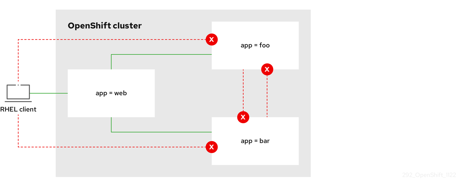
24.4.4.8. Creating a multi-network policy allowing traffic to an application from all namespaces
If you log in with a user with the cluster-admin role, then you can create a network policy in any namespace in the cluster.
Follow this procedure to configure a policy that allows traffic from all pods in all namespaces to a particular application.
Prerequisites
-
Your cluster uses a network plugin that supports
NetworkPolicyobjects, such as the OVN-Kubernetes network plugin or the OpenShift SDN network plugin withmode: NetworkPolicyset. This mode is the default for OpenShift SDN. -
You installed the OpenShift CLI (
oc). -
You are logged in to the cluster with a user with
cluster-adminprivileges. - You are working in the namespace that the multi-network policy applies to.
Procedure
Create a policy that allows traffic from all pods in all namespaces to a particular application. Save the YAML in the
web-allow-all-namespaces.yamlfile:apiVersion: k8s.cni.cncf.io/v1beta1 kind: MultiNetworkPolicy metadata: name: web-allow-all-namespaces namespace: default annotations: k8s.v1.cni.cncf.io/policy-for:<namespace_name>/<network_name> spec: podSelector: matchLabels: app: web1 policyTypes: - Ingress ingress: - from: - namespaceSelector: {}2 NoteBy default, if you omit specifying a
namespaceSelectorit does not select any namespaces, which means the policy allows traffic only from the namespace the network policy is deployed to.Apply the policy by entering the following command:
$ oc apply -f web-allow-all-namespaces.yamlExample output
multinetworkpolicy.k8s.cni.cncf.io/web-allow-all-namespaces created
Verification
Start a web service in the
defaultnamespace by entering the following command:$ oc run web --namespace=default --image=nginx --labels="app=web" --expose --port=80Run the following command to deploy an
alpineimage in thesecondarynamespace and to start a shell:$ oc run test-$RANDOM --namespace=secondary --rm -i -t --image=alpine -- shRun the following command in the shell and observe that the request is allowed:
# wget -qO- --timeout=2 http://web.defaultExpected output
<!DOCTYPE html>
<html>
<head>
<title>Welcome to nginx!</title>
<style>
html { color-scheme: light dark; }
body { width: 35em; margin: 0 auto;
font-family: Tahoma, Verdana, Arial, sans-serif; }
</style>
</head>
<body>
<h1>Welcome to nginx!</h1>
<p>If you see this page, the nginx web server is successfully installed and
working. Further configuration is required.</p>

<p>For online documentation and support please refer to
<a href="http://nginx.org/">nginx.org</a>.<br/>
Commercial support is available at
<a href="http://nginx.com/">nginx.com</a>.</p>

<p><em>Thank you for using nginx.</em></p>
</body>
</html>
24.4.4.9. Creating a multi-network policy allowing traffic to an application from a namespace
If you log in with a user with the cluster-admin role, then you can create a network policy in any namespace in the cluster.
Follow this procedure to configure a policy that allows traffic to a pod with the label app=web from a particular namespace. You might want to do this to:
- Restrict traffic to a production database only to namespaces where production workloads are deployed.
- Enable monitoring tools deployed to a particular namespace to scrape metrics from the current namespace.
Prerequisites
-
Your cluster uses a network plugin that supports
NetworkPolicyobjects, such as the OVN-Kubernetes network plugin or the OpenShift SDN network plugin withmode: NetworkPolicyset. This mode is the default for OpenShift SDN. -
You installed the OpenShift CLI (
oc). -
You are logged in to the cluster with a user with
cluster-adminprivileges. - You are working in the namespace that the multi-network policy applies to.
Procedure
Create a policy that allows traffic from all pods in a particular namespaces with a label
purpose=production. Save the YAML in theweb-allow-prod.yamlfile:apiVersion: k8s.cni.cncf.io/v1beta1 kind: MultiNetworkPolicy metadata: name: web-allow-prod namespace: default annotations: k8s.v1.cni.cncf.io/policy-for:<namespace_name>/<network_name> spec: podSelector: matchLabels: app: web1 policyTypes: - Ingress ingress: - from: - namespaceSelector: matchLabels: purpose: production2 Apply the policy by entering the following command:
$ oc apply -f web-allow-prod.yamlExample output
multinetworkpolicy.k8s.cni.cncf.io/web-allow-prod created
Verification
Start a web service in the
defaultnamespace by entering the following command:$ oc run web --namespace=default --image=nginx --labels="app=web" --expose --port=80Run the following command to create the
prodnamespace:$ oc create namespace prodRun the following command to label the
prodnamespace:$ oc label namespace/prod purpose=productionRun the following command to create the
devnamespace:$ oc create namespace devRun the following command to label the
devnamespace:$ oc label namespace/dev purpose=testingRun the following command to deploy an
alpineimage in thedevnamespace and to start a shell:$ oc run test-$RANDOM --namespace=dev --rm -i -t --image=alpine -- shRun the following command in the shell and observe that the request is blocked:
# wget -qO- --timeout=2 http://web.defaultExpected output
wget: download timed outRun the following command to deploy an
alpineimage in theprodnamespace and start a shell:$ oc run test-$RANDOM --namespace=prod --rm -i -t --image=alpine -- shRun the following command in the shell and observe that the request is allowed:
# wget -qO- --timeout=2 http://web.defaultExpected output
<!DOCTYPE html>
<html>
<head>
<title>Welcome to nginx!</title>
<style>
html { color-scheme: light dark; }
body { width: 35em; margin: 0 auto;
font-family: Tahoma, Verdana, Arial, sans-serif; }
</style>
</head>
<body>
<h1>Welcome to nginx!</h1>
<p>If you see this page, the nginx web server is successfully installed and
working. Further configuration is required.</p>

<p>For online documentation and support please refer to
<a href="http://nginx.org/">nginx.org</a>.<br/>
Commercial support is available at
<a href="http://nginx.com/">nginx.com</a>.</p>

<p><em>Thank you for using nginx.</em></p>
</body>
</html>
24.5. Attaching a pod to an additional network
As a cluster user you can attach a pod to an additional network.
24.5.1. Adding a pod to an additional network
You can add a pod to an additional network. The pod continues to send normal cluster-related network traffic over the default network.
When a pod is created additional networks are attached to it. However, if a pod already exists, you cannot attach additional networks to it.
The pod must be in the same namespace as the additional network.
Prerequisites
-
Install the OpenShift CLI (
oc). - Log in to the cluster.
Procedure
Add an annotation to the
Podobject. Only one of the following annotation formats can be used:To attach an additional network without any customization, add an annotation with the following format. Replace
<network>with the name of the additional network to associate with the pod:metadata: annotations: k8s.v1.cni.cncf.io/networks: <network>[,<network>,...]1 - 1
- To specify more than one additional network, separate each network with a comma. Do not include whitespace between the comma. If you specify the same additional network multiple times, that pod will have multiple network interfaces attached to that network.
To attach an additional network with customizations, add an annotation with the following format:
metadata:
  annotations:
    k8s.v1.cni.cncf.io/networks: |-
      [
        {
          "name": "<network>",
1 "namespace": "<namespace>",2 "default-route": ["<default-route>"]3 } ]
To create the pod, enter the following command. Replace
<name>with the name of the pod.$ oc create -f <name>.yamlOptional: To Confirm that the annotation exists in the
PodCR, enter the following command, replacing<name>with the name of the pod.$ oc get pod <name> -o yamlIn the following example, the
example-podpod is attached to thenet1additional network:$ oc get pod example-pod -o yaml apiVersion: v1 kind: Pod metadata: annotations: k8s.v1.cni.cncf.io/networks: macvlan-bridge k8s.v1.cni.cncf.io/network-status: |-1 [{ "name": "openshift-sdn", "interface": "eth0", "ips": [ "10.128.2.14" ], "default": true, "dns": {} },{ "name": "macvlan-bridge", "interface": "net1", "ips": [ "20.2.2.100" ], "mac": "22:2f:60:a5:f8:00", "dns": {} }] name: example-pod namespace: default spec: ... status: ...- 1
- The
k8s.v1.cni.cncf.io/network-statusparameter is a JSON array of objects. Each object describes the status of an additional network attached to the pod. The annotation value is stored as a plain text value.
24.5.1.1. Specifying pod-specific addressing and routing options
When attaching a pod to an additional network, you may want to specify further properties about that network in a particular pod. This allows you to change some aspects of routing, as well as specify static IP addresses and MAC addresses. To accomplish this, you can use the JSON formatted annotations.
Prerequisites
- The pod must be in the same namespace as the additional network.
-
Install the OpenShift CLI (
oc). - You must log in to the cluster.
Procedure
To add a pod to an additional network while specifying addressing and/or routing options, complete the following steps:
Edit the
Podresource definition. If you are editing an existingPodresource, run the following command to edit its definition in the default editor. Replace<name>with the name of thePodresource to edit.$ oc edit pod <name>In the
Podresource definition, add thek8s.v1.cni.cncf.io/networksparameter to the podmetadatamapping. Thek8s.v1.cni.cncf.io/networksaccepts a JSON string of a list of objects that reference the name ofNetworkAttachmentDefinitioncustom resource (CR) names in addition to specifying additional properties.metadata: annotations: k8s.v1.cni.cncf.io/networks: '[<network>[,<network>,...]]'1 - 1
- Replace
<network>with a JSON object as shown in the following examples. The single quotes are required.
In the following example the annotation specifies which network attachment will have the default route, using the
default-routeparameter.apiVersion: v1 kind: Pod metadata: name: example-pod annotations: k8s.v1.cni.cncf.io/networks: '[ { "name": "net1" }, { "name": "net2",1 "default-route": ["192.0.2.1"]2 }]' spec: containers: - name: example-pod command: ["/bin/bash", "-c", "sleep 2000000000000"] image: centos/tools- 1
- The
namekey is the name of the additional network to associate with the pod. - 2
- The
default-routekey specifies a value of a gateway for traffic to be routed over if no other routing entry is present in the routing table. If more than onedefault-routekey is specified, this will cause the pod to fail to become active.
The default route will cause any traffic that is not specified in other routes to be routed to the gateway.
Setting the default route to an interface other than the default network interface for OpenShift Container Platform may cause traffic that is anticipated for pod-to-pod traffic to be routed over another interface.
To verify the routing properties of a pod, the oc command may be used to execute the ip command within a pod.
$ oc exec -it <pod_name> -- ip route
You may also reference the pod’s k8s.v1.cni.cncf.io/network-status to see which additional network has been assigned the default route, by the presence of the default-route key in the JSON-formatted list of objects.
To set a static IP address or MAC address for a pod you can use the JSON formatted annotations. This requires you create networks that specifically allow for this functionality. This can be specified in a rawCNIConfig for the CNO.
Edit the CNO CR by running the following command:
$ oc edit networks.operator.openshift.io cluster
The following YAML describes the configuration parameters for the CNO:
Cluster Network Operator YAML configuration
name: <name>
namespace: <namespace>
rawCNIConfig: '{
...
}'
type: Raw- 1
- Specify a name for the additional network attachment that you are creating. The name must be unique within the specified
namespace. - 2
- Specify the namespace to create the network attachment in. If you do not specify a value, then the
defaultnamespace is used. - 3
- Specify the CNI plugin configuration in JSON format, which is based on the following template.
The following object describes the configuration parameters for utilizing static MAC address and IP address using the macvlan CNI plugin:
macvlan CNI plugin JSON configuration object using static IP and MAC address
{
"cniVersion": "0.3.1",
"name": "<name>",
"plugins": [{
"type": "macvlan",
"capabilities": { "ips": true },
"master": "eth0",
"mode": "bridge",
"ipam": {
"type": "static"
}
}, {
"capabilities": { "mac": true },
"type": "tuning"
}]
}- 1
- Specifies the name for the additional network attachment to create. The name must be unique within the specified
namespace. - 2
- Specifies an array of CNI plugin configurations. The first object specifies a macvlan plugin configuration and the second object specifies a tuning plugin configuration.
- 3
- Specifies that a request is made to enable the static IP address functionality of the CNI plugin runtime configuration capabilities.
- 4
- Specifies the interface that the macvlan plugin uses.
- 5
- Specifies that a request is made to enable the static MAC address functionality of a CNI plugin.
The above network attachment can be referenced in a JSON formatted annotation, along with keys to specify which static IP and MAC address will be assigned to a given pod.
Edit the pod with:
$ oc edit pod <name>macvlan CNI plugin JSON configuration object using static IP and MAC address
apiVersion: v1
kind: Pod
metadata:
name: example-pod
annotations:
k8s.v1.cni.cncf.io/networks: '[
{
"name": "<name>",
"ips": [ "192.0.2.205/24" ],
"mac": "CA:FE:C0:FF:EE:00"
        }
]'Static IP addresses and MAC addresses do not have to be used at the same time, you may use them individually, or together.
To verify the IP address and MAC properties of a pod with additional networks, use the oc command to execute the ip command within a pod.
$ oc exec -it <pod_name> -- ip a24.6. Removing a pod from an additional network
As a cluster user you can remove a pod from an additional network.
24.6.1. Removing a pod from an additional network
You can remove a pod from an additional network only by deleting the pod.
Prerequisites
- An additional network is attached to the pod.
-
Install the OpenShift CLI (
oc). - Log in to the cluster.
Procedure
To delete the pod, enter the following command:
$ oc delete pod <name> -n <namespace>-
<name>is the name of the pod. -
<namespace>is the namespace that contains the pod.
-
24.7. Editing an additional network
As a cluster administrator you can modify the configuration for an existing additional network.
24.7.1. Modifying an additional network attachment definition
As a cluster administrator, you can make changes to an existing additional network. Any existing pods attached to the additional network will not be updated.
Prerequisites
- You have configured an additional network for your cluster.
-
Install the OpenShift CLI (
oc). -
Log in as a user with
cluster-adminprivileges.
Procedure
To edit an additional network for your cluster, complete the following steps:
Run the following command to edit the Cluster Network Operator (CNO) CR in your default text editor:
$ oc edit networks.operator.openshift.io cluster-
In the
additionalNetworkscollection, update the additional network with your changes. - Save your changes and quit the text editor to commit your changes.
Optional: Confirm that the CNO updated the
NetworkAttachmentDefinitionobject by running the following command. Replace<network-name>with the name of the additional network to display. There might be a delay before the CNO updates theNetworkAttachmentDefinitionobject to reflect your changes.$ oc get network-attachment-definitions <network-name> -o yamlFor example, the following console output displays a
NetworkAttachmentDefinitionobject that is namednet1:$ oc get network-attachment-definitions net1 -o go-template='{{printf "%s\n" .spec.config}}' { "cniVersion": "0.3.1", "type": "macvlan", "master": "ens5", "mode": "bridge", "ipam": {"type":"static","routes":[{"dst":"0.0.0.0/0","gw":"10.128.2.1"}],"addresses":[{"address":"10.128.2.100/23","gateway":"10.128.2.1"}],"dns":{"nameservers":["172.30.0.10"],"domain":"us-west-2.compute.internal","search":["us-west-2.compute.internal"]}} }
24.8. Removing an additional network
As a cluster administrator you can remove an additional network attachment.
24.8.1. Removing an additional network attachment definition
As a cluster administrator, you can remove an additional network from your OpenShift Container Platform cluster. The additional network is not removed from any pods it is attached to.
Prerequisites
-
Install the OpenShift CLI (
oc). -
Log in as a user with
cluster-adminprivileges.
Procedure
To remove an additional network from your cluster, complete the following steps:
Edit the Cluster Network Operator (CNO) in your default text editor by running the following command:
$ oc edit networks.operator.openshift.io clusterModify the CR by removing the configuration from the
additionalNetworkscollection for the network attachment definition you are removing.apiVersion: operator.openshift.io/v1 kind: Network metadata: name: cluster spec: additionalNetworks: []1 - 1
- If you are removing the configuration mapping for the only additional network attachment definition in the
additionalNetworkscollection, you must specify an empty collection.
- Save your changes and quit the text editor to commit your changes.
Optional: Confirm that the additional network CR was deleted by running the following command:
$ oc get network-attachment-definition --all-namespaces
24.9. Assigning a secondary network to a VRF
As a cluster administrator, you can configure an additional network for a virtual routing and forwarding (VRF) domain by using the CNI VRF plugin. The virtual network that this plugin creates is associated with the physical interface that you specify.
Using a secondary network with a VRF instance has the following advantages:
- Workload isolation
- Isolate workload traffic by configuring a VRF instance for the additional network.
- Improved security
- Enable improved security through isolated network paths in the VRF domain.
- Multi-tenancy support
- Support multi-tenancy through network segmentation with a unique routing table in the VRF domain for each tenant.
Applications that use VRFs must bind to a specific device. The common usage is to use the SO_BINDTODEVICE option for a socket. The SO_BINDTODEVICE option binds the socket to the device that is specified in the passed interface name, for example, eth1. To use the SO_BINDTODEVICE option, the application must have CAP_NET_RAW capabilities.
Using a VRF through the ip vrf exec command is not supported in OpenShift Container Platform pods. To use VRF, bind applications directly to the VRF interface.
24.9.1. Creating an additional network attachment with the CNI VRF plugin
The Cluster Network Operator (CNO) manages additional network definitions. When you specify an additional network to create, the CNO creates the NetworkAttachmentDefinition custom resource (CR) automatically.
Do not edit the NetworkAttachmentDefinition CRs that the Cluster Network Operator manages. Doing so might disrupt network traffic on your additional network.
To create an additional network attachment with the CNI VRF plugin, perform the following procedure.
Prerequisites
- Install the OpenShift Container Platform CLI (oc).
- Log in to the OpenShift cluster as a user with cluster-admin privileges.
Procedure
Create the
Networkcustom resource (CR) for the additional network attachment and insert therawCNIConfigconfiguration for the additional network, as in the following example CR. Save the YAML as the fileadditional-network-attachment.yaml.apiVersion: operator.openshift.io/v1 kind: Network metadata: name: cluster spec: additionalNetworks: - name: test-network-1 namespace: additional-network-1 type: Raw rawCNIConfig: '{ "cniVersion": "0.3.1", "name": "macvlan-vrf", "plugins": [1 { "type": "macvlan", "master": "eth1", "ipam": { "type": "static", "addresses": [ { "address": "191.168.1.23/24" } ] } }, { "type": "vrf",2 "vrfname": "vrf-1",3 "table": 10014 }] }'- 1
pluginsmust be a list. The first item in the list must be the secondary network underpinning the VRF network. The second item in the list is the VRF plugin configuration.- 2
typemust be set tovrf.- 3
vrfnameis the name of the VRF that the interface is assigned to. If it does not exist in the pod, it is created.- 4
- Optional.
tableis the routing table ID. By default, thetableidparameter is used. If it is not specified, the CNI assigns a free routing table ID to the VRF.
NoteVRF functions correctly only when the resource is of type
netdevice.Create the
Networkresource:$ oc create -f additional-network-attachment.yamlConfirm that the CNO created the
NetworkAttachmentDefinitionCR by running the following command. Replace<namespace>with the namespace that you specified when configuring the network attachment, for example,additional-network-1.$ oc get network-attachment-definitions -n <namespace>Example output
NAME AGE additional-network-1 14mNoteThere might be a delay before the CNO creates the CR.
Verification
Create a pod and assign it to the additional network with the VRF instance:
Create a YAML file that defines the
Podresource:Example
pod-additional-net.yamlfileapiVersion: v1 kind: Pod metadata: name: pod-additional-net annotations: k8s.v1.cni.cncf.io/networks: '[ { "name": "test-network-1"1 } ]' spec: containers: - name: example-pod-1 command: ["/bin/bash", "-c", "sleep 9000000"] image: centos:8- 1
- Specify the name of the additional network with the VRF instance.
Create the
Podresource by running the following command:$ oc create -f pod-additional-net.yamlExample output
pod/test-pod created
Verify that the pod network attachment is connected to the VRF additional network. Start a remote session with the pod and run the following command:
$ ip vrf showExample output
Name              Table
-----------------------
vrf-1             1001
Confirm that the VRF interface is the controller for the additional interface:
$ ip linkExample output
5: net1: <BROADCAST,MULTICAST,UP,LOWER_UP> mtu 1500 qdisc noqueue master red state UP mode