Chapter 26. OVN-Kubernetes network plugin
26.1. About the OVN-Kubernetes network plugin
The OpenShift Container Platform cluster uses a virtualized network for pod and service networks.
Part of Red Hat OpenShift Networking, the OVN-Kubernetes network plugin is the default network provider for OpenShift Container Platform. OVN-Kubernetes is based on Open Virtual Network (OVN) and provides an overlay-based networking implementation. A cluster that uses the OVN-Kubernetes plugin also runs Open vSwitch (OVS) on each node. OVN configures OVS on each node to implement the declared network configuration.
OVN-Kubernetes is the default networking solution for OpenShift Container Platform and single-node OpenShift deployments.
OVN-Kubernetes, which arose from the OVS project, uses many of the same constructs, such as open flow rules, to decide how packets travel through the network. For more information, see the Open Virtual Network website.
OVN-Kubernetes is a series of daemons for OVS that transform virtual network configurations into OpenFlow rules. OpenFlow is a protocol for communicating with network switches and routers, providing a means for remotely controlling the flow of network traffic on a network device. This means that network administrators can configure, manage, and watch the flow of network traffic.
OVN-Kubernetes provides more of the advanced functionality not available with OpenFlow. OVN supports distributed virtual routing, distributed logical switches, access control, Dynamic Host Configuration Protocol (DHCP), and DNS. OVN implements distributed virtual routing within logic flows that equate to open flows. For example, if you have a pod that sends out a DHCP request to the DHCP server on the network, a logic flow rule in the request helps the OVN-Kubernetes handle the packet. This means that the server can respond with gateway, DNS server, IP address, and other information.
OVN-Kubernetes runs a daemon on each node. There are daemon sets for the databases and for the OVN controller that run on every node. The OVN controller programs the Open vSwitch daemon on the nodes to support the following network provider features:
- Egress IPs
- Firewalls
- Hardware offloading
- Hybrid networking
- Internet Protocol Security (IPsec) encryption
- IPv6
- Multicast.
- Network policy and network policy logs
- Routers
26.1.1. OVN-Kubernetes purpose
The OVN-Kubernetes network plugin is an open-source, fully-featured Kubernetes CNI plugin that uses Open Virtual Network (OVN) to manage network traffic flows. OVN is a community developed, vendor-agnostic network virtualization solution. The OVN-Kubernetes network plugin:
- Uses OVN (Open Virtual Network) to manage network traffic flows. OVN is a community developed, vendor-agnostic network virtualization solution.
- Implements Kubernetes network policy support, including ingress and egress rules.
- Uses the Geneve (Generic Network Virtualization Encapsulation) protocol rather than VXLAN to create an overlay network between nodes.
The OVN-Kubernetes network plugin provides the following advantages over OpenShift SDN.
- Full support for IPv6 single-stack and IPv4/IPv6 dual-stack networking on supported platforms
- Support for hybrid clusters with both Linux and Microsoft Windows workloads
- Optional IPsec encryption of intra-cluster communications
- Offload of network data processing from host CPU to compatible network cards and data processing units (DPUs)
26.1.2. Supported network plugin feature matrix
Red Hat OpenShift Networking offers two options for the network plugin, OpenShift SDN and OVN-Kubernetes, for the network plugin. The following table summarizes the current feature support for both network plugins:
| Feature | OpenShift SDN | OVN-Kubernetes |
|---|---|---|
| Egress IPs | Supported | Supported |
| Egress firewall | Supported | Supported [1] |
| Egress router | Supported | Supported [2] |
| Hybrid networking | Not supported | Supported |
| IPsec encryption for intra-cluster communication | Not supported | Supported |
| IPv4 single-stack | Supported | Supported |
| IPv6 single-stack | Not supported | Supported [3] |
| IPv4/IPv6 dual-stack | Not Supported | Supported [4] |
| IPv6/IPv4 dual-stack | Not supported | Supported [5] |
| Kubernetes network policy | Supported | Supported |
| Kubernetes network policy logs | Not supported | Supported |
| Hardware offloading | Not supported | Supported |
| Multicast | Supported | Supported |
- Egress firewall is also known as egress network policy in OpenShift SDN. This is not the same as network policy egress.
- Egress router for OVN-Kubernetes supports only redirect mode.
- IPv6 single-stack networking on a bare-metal platform.
- IPv4/IPv6 dual-stack networking on bare-metal, VMware vSphere (installer-provisioned infrastructure installations only), IBM Power®, IBM Z®, and RHOSP platforms.
- IPv6/IPv4 dual-stack networking on bare-metal, VMware vSphere (installer-provisioned infrastructure installations only), and IBM Power® platforms.
26.1.3. OVN-Kubernetes IPv6 and dual-stack limitations
The OVN-Kubernetes network plugin has the following limitations:
For clusters configured for dual-stack networking, both IPv4 and IPv6 traffic must use the same network interface as the default gateway.
If this requirement is not met, pods on the host in the
ovnkube-nodedaemon set enter theCrashLoopBackOffstate.If you display a pod with a command such as
oc get pod -n openshift-ovn-kubernetes -l app=ovnkube-node -o yaml, thestatusfield has more than one message about the default gateway, as shown in the following output:I1006 16:09:50.985852 60651 helper_linux.go:73] Found default gateway interface br-ex 192.168.127.1 I1006 16:09:50.985923 60651 helper_linux.go:73] Found default gateway interface ens4 fe80::5054:ff:febe:bcd4 F1006 16:09:50.985939 60651 ovnkube.go:130] multiple gateway interfaces detected: br-ex ens4The only resolution is to reconfigure the host networking so that both IP families use the same network interface for the default gateway.
For clusters configured for dual-stack networking, both the IPv4 and IPv6 routing tables must contain the default gateway.
If this requirement is not met, pods on the host in the
ovnkube-nodedaemon set enter theCrashLoopBackOffstate.If you display a pod with a command such as
oc get pod -n openshift-ovn-kubernetes -l app=ovnkube-node -o yaml, thestatusfield has more than one message about the default gateway, as shown in the following output:I0512 19:07:17.589083 108432 helper_linux.go:74] Found default gateway interface br-ex 192.168.123.1 F0512 19:07:17.589141 108432 ovnkube.go:133] failed to get default gateway interfaceThe only resolution is to reconfigure the host networking so that both IP families contain the default gateway.
-
If you set the
ipv6.disableparameter to1in thekernelArgumentsection of theMachineConfigcustom resource (CR) for your cluster, OVN-Kubernetes pods enter aCrashLoopBackOffstate. Additionally, updating your cluster to a later version of OpenShift Container Platform fails because the Network Operator remains on aDegradedstate. Red Hat does not support disabling IPv6 addresses for your cluster so do not set theipv6.disableparameter to1.
26.1.4. Session affinity
Session affinity is a feature that applies to Kubernetes Service objects. You can use session affinity if you want to ensure that each time you connect to a <service_VIP>:<Port>, the traffic is always load balanced to the same back end. For more information, including how to set session affinity based on a client’s IP address, see Session affinity.
26.1.4.1. Stickiness timeout for session affinity
The OVN-Kubernetes network plugin for OpenShift Container Platform calculates the stickiness timeout for a session from a client based on the last packet. For example, if you run a curl command 10 times, the sticky session timer starts from the tenth packet not the first. As a result, if the client is continuously contacting the service, then the session never times out. The timeout starts when the service has not received a packet for the amount of time set by the timeoutSeconds parameter.
26.2. OVN-Kubernetes architecture
26.2.1. Introduction to OVN-Kubernetes architecture
The following diagram shows the OVN-Kubernetes architecture.
Figure 26.1. OVK-Kubernetes architecture

The key components are:
- Cloud Management System (CMS) - A platform specific client for OVN that provides a CMS specific plugin for OVN integration. The plugin translates the cloud management system’s concept of the logical network configuration, stored in the CMS configuration database in a CMS-specific format, into an intermediate representation understood by OVN.
-
OVN Northbound database (
nbdb) container - Stores the logical network configuration passed by the CMS plugin. -
OVN Southbound database (
sbdb) container - Stores the physical and logical network configuration state for Open vSwitch (OVS) system on each node, including tables that bind them. -
OVN north daemon (
ovn-northd) - This is the intermediary client betweennbdbcontainer andsbdbcontainer. It translates the logical network configuration in terms of conventional network concepts, taken from thenbdbcontainer, into logical data path flows in thesbdbcontainer. The container name forovn-northddaemon isnorthdand it runs in theovnkube-nodepods. -
ovn-controller - This is the OVN agent that interacts with OVS and hypervisors, for any information or update that is needed for
sbdbcontainer. Theovn-controllerreads logical flows from thesbdbcontainer, translates them intoOpenFlowflows and sends them to the node’s OVS daemon. The container name isovn-controllerand it runs in theovnkube-nodepods.
The OVN northd, northbound database, and southbound database run on each node in the cluster and mostly contain and process information that is local to that node.
The OVN northbound database has the logical network configuration passed down to it by the cloud management system (CMS). The OVN northbound database contains the current desired state of the network, presented as a collection of logical ports, logical switches, logical routers, and more. The ovn-northd (northd container) connects to the OVN northbound database and the OVN southbound database. It translates the logical network configuration in terms of conventional network concepts, taken from the OVN northbound database, into logical data path flows in the OVN southbound database.
The OVN southbound database has physical and logical representations of the network and binding tables that link them together. It contains the chassis information of the node and other constructs like remote transit switch ports that are required to connect to the other nodes in the cluster. The OVN southbound database also contains all the logic flows. The logic flows are shared with the ovn-controller process that runs on each node and the ovn-controller turns those into OpenFlow rules to program Open vSwitch(OVS).
The Kubernetes control plane nodes contain two ovnkube-control-plane pods on separate nodes, which perform the central IP address management (IPAM) allocation for each node in the cluster. At any given time, a single ovnkube-control-plane pod is the leader.
26.2.2. Listing all resources in the OVN-Kubernetes project
Finding the resources and containers that run in the OVN-Kubernetes project is important to help you understand the OVN-Kubernetes networking implementation.
Prerequisites
-
Access to the cluster as a user with the
cluster-adminrole. -
The OpenShift CLI (
oc) installed.
Procedure
Run the following command to get all resources, endpoints, and
ConfigMapsin the OVN-Kubernetes project:$ oc get all,ep,cm -n openshift-ovn-kubernetesExample output
Warning: apps.openshift.io/v1 DeploymentConfig is deprecated in v4.14+, unavailable in v4.10000+
NAME                                         READY   STATUS    RESTARTS       AGE
pod/ovnkube-control-plane-65c6f55656-6d55h   2/2     Running   0              114m
pod/ovnkube-control-plane-65c6f55656-fd7vw   2/2     Running   2 (104m ago)   114m
pod/ovnkube-node-bcvts                       8/8     Running   0              113m
pod/ovnkube-node-drgvv                       8/8     Running   0              113m
pod/ovnkube-node-f2pxt                       8/8     Running   0              113m
pod/ovnkube-node-frqsb                       8/8     Running   0              105m
pod/ovnkube-node-lbxkk                       8/8     Running   0              105m
pod/ovnkube-node-tt7bx                       8/8     Running   1 (102m ago)   105m

NAME                                   TYPE        CLUSTER-IP   EXTERNAL-IP   PORT(S)             AGE
service/ovn-kubernetes-control-plane   ClusterIP   None         <none>        9108/TCP            114m
service/ovn-kubernetes-node            ClusterIP   None         <none>        9103/TCP,9105/TCP   114m

NAME                          DESIRED   CURRENT   READY   UP-TO-DATE   AVAILABLE   NODE SELECTOR                 AGE
daemonset.apps/ovnkube-node   6         6         6       6            6           beta.kubernetes.io/os=linux   114m

NAME                                    READY   UP-TO-DATE   AVAILABLE   AGE
deployment.apps/ovnkube-control-plane   3/3     3            3           114m

NAME                                               DESIRED   CURRENT   READY   AGE
replicaset.apps/ovnkube-control-plane-65c6f55656   3         3         3       114m

NAME                                     ENDPOINTS                                               AGE
endpoints/ovn-kubernetes-control-plane   10.0.0.3:9108,10.0.0.4:9108,10.0.0.5:9108               114m
endpoints/ovn-kubernetes-node            10.0.0.3:9105,10.0.0.4:9105,10.0.0.5:9105 + 9 more...   114m

NAME                                 DATA   AGE
configmap/control-plane-status       1      113m
configmap/kube-root-ca.crt           1      114m
configmap/openshift-service-ca.crt   1      114m
configmap/ovn-ca                     1      114m
configmap/ovnkube-config             1      114m
configmap/signer-ca                  1      114m
There is one
ovnkube-nodepod for each node in the cluster. Theovnkube-configconfig map has the OpenShift Container Platform OVN-Kubernetes configurations.List all of the containers in the
ovnkube-nodepods by running the following command:$ oc get pods ovnkube-node-bcvts -o jsonpath='{.spec.containers[*].name}' -n openshift-ovn-kubernetesExpected output
ovn-controller ovn-acl-logging kube-rbac-proxy-node kube-rbac-proxy-ovn-metrics northd nbdb sbdb ovnkube-controllerThe
ovnkube-nodepod is made up of several containers. It is responsible for hosting the northbound database (nbdbcontainer), the southbound database (sbdbcontainer), the north daemon (northdcontainer),ovn-controllerand theovnkube-controllercontainer. Theovnkube-controllercontainer watches for API objects like pods, egress IPs, namespaces, services, endpoints, egress firewall, and network policies. It is also responsible for allocating pod IP from the available subnet pool for that node.List all the containers in the
ovnkube-control-planepods by running the following command:$ oc get pods ovnkube-control-plane-65c6f55656-6d55h -o jsonpath='{.spec.containers[*].name}' -n openshift-ovn-kubernetesExpected output
kube-rbac-proxy ovnkube-cluster-managerThe
ovnkube-control-planepod has a container (ovnkube-cluster-manager) that resides on each OpenShift Container Platform node. Theovnkube-cluster-managercontainer allocates pod subnet, transit switch subnet IP and join switch subnet IP to each node in the cluster. Thekube-rbac-proxycontainer monitors metrics for theovnkube-cluster-managercontainer.
26.2.3. Listing the OVN-Kubernetes northbound database contents
Each node is controlled by the ovnkube-controller container running in the ovnkube-node pod on that node. To understand the OVN logical networking entities you need to examine the northbound database that is running as a container inside the ovnkube-node pod on that node to see what objects are in the node you wish to see.
Prerequisites
-
Access to the cluster as a user with the
cluster-adminrole. -
The OpenShift CLI (
oc) installed.
To run ovn nbctl or sbctl commands in a cluster you must open a remote shell into the nbdb or sbdb containers on the relevant node
List pods by running the following command:
$ oc get po -n openshift-ovn-kubernetesExample output
NAME                                     READY   STATUS    RESTARTS      AGE
ovnkube-control-plane-8444dff7f9-4lh9k   2/2     Running   0             27m
ovnkube-control-plane-8444dff7f9-5rjh9   2/2     Running   0             27m
ovnkube-node-55xs2                       8/8     Running   0             26m
ovnkube-node-7r84r                       8/8     Running   0             16m
ovnkube-node-bqq8p                       8/8     Running   0             17m
ovnkube-node-mkj4f                       8/8     Running   0             26m
ovnkube-node-mlr8k                       8/8     Running   0             26m
ovnkube-node-wqn2m                       8/8     Running   0             16m
Optional: To list the pods with node information, run the following command:
$ oc get pods -n openshift-ovn-kubernetes -owideExample output
NAME                                     READY   STATUS    RESTARTS      AGE   IP           NODE                                       NOMINATED NODE   READINESS GATES
ovnkube-control-plane-8444dff7f9-4lh9k   2/2     Running   0             27m   10.0.0.3     ci-ln-t487nnb-72292-mdcnq-master-1         <none>           <none>
ovnkube-control-plane-8444dff7f9-5rjh9   2/2     Running   0             27m   10.0.0.4     ci-ln-t487nnb-72292-mdcnq-master-2         <none>           <none>
ovnkube-node-55xs2                       8/8     Running   0             26m   10.0.0.4     ci-ln-t487nnb-72292-mdcnq-master-2         <none>           <none>
ovnkube-node-7r84r                       8/8     Running   0             17m   10.0.128.3   ci-ln-t487nnb-72292-mdcnq-worker-b-wbz7z   <none>           <none>
ovnkube-node-bqq8p                       8/8     Running   0             17m   10.0.128.2   ci-ln-t487nnb-72292-mdcnq-worker-a-lh7ms   <none>           <none>
ovnkube-node-mkj4f                       8/8     Running   0             27m   10.0.0.5     ci-ln-t487nnb-72292-mdcnq-master-0         <none>           <none>
ovnkube-node-mlr8k                       8/8     Running   0             27m   10.0.0.3     ci-ln-t487nnb-72292-mdcnq-master-1         <none>           <none>
ovnkube-node-wqn2m                       8/8     Running   0             17m   10.0.128.4   ci-ln-t487nnb-72292-mdcnq-worker-c-przlm   <none>           <none>
Navigate into a pod to look at the northbound database by running the following command:
$ oc rsh -c nbdb -n openshift-ovn-kubernetes ovnkube-node-55xs2Run the following command to show all the objects in the northbound database:
$ ovn-nbctl showThe output is too long to list here. The list includes the NAT rules, logical switches, load balancers and so on.
You can narrow down and focus on specific components by using some of the following optional commands:
Run the following command to show the list of logical routers:
$ oc exec -n openshift-ovn-kubernetes -it ovnkube-node-55xs2 \
-c northd -- ovn-nbctl lr-list
Example output
45339f4f-7d0b-41d0-b5f9-9fca9ce40ce6 (GR_ci-ln-t487nnb-72292-mdcnq-master-2) 96a0a0f0-e7ed-4fec-8393-3195563de1b8 (ovn_cluster_router)NoteFrom this output you can see there is router on each node plus an
ovn_cluster_router.Run the following command to show the list of logical switches:
$ oc exec -n openshift-ovn-kubernetes -it ovnkube-node-55xs2 \
-c nbdb -- ovn-nbctl ls-list
Example output
bdd7dc3d-d848-4a74-b293-cc15128ea614 (ci-ln-t487nnb-72292-mdcnq-master-2) b349292d-ee03-4914-935f-1940b6cb91e5 (ext_ci-ln-t487nnb-72292-mdcnq-master-2) 0aac0754-ea32-4e33-b086-35eeabf0a140 (join) 992509d7-2c3f-4432-88db-c179e43592e5 (transit_switch)NoteFrom this output you can see there is an ext switch for each node plus switches with the node name itself and a join switch.
Run the following command to show the list of load balancers:
$ oc exec -n openshift-ovn-kubernetes -it ovnkube-node-55xs2 \
-c nbdb -- ovn-nbctl lb-list
Example output
UUID LB PROTO VIP IPs 7c84c673-ed2a-4436-9a1f-9bc5dd181eea Service_default/ tcp 172.30.0.1:443 10.0.0.3:6443,169.254.169.2:6443,10.0.0.5:6443 4d663fd9-ddc8-4271-b333-4c0e279e20bb Service_default/ tcp 172.30.0.1:443 10.0.0.3:6443,10.0.0.4:6443,10.0.0.5:6443 292eb07f-b82f-4962-868a-4f541d250bca Service_openshif tcp 172.30.105.247:443 10.129.0.12:8443 034b5a7f-bb6a-45e9-8e6d-573a82dc5ee3 Service_openshif tcp 172.30.192.38:443 10.0.0.3:10259,10.0.0.4:10259,10.0.0.5:10259 a68bb53e-be84-48df-bd38-bdd82fcd4026 Service_openshif tcp 172.30.161.125:8443 10.129.0.32:8443 6cc21b3d-2c54-4c94-8ff5-d8e017269c2e Service_openshif tcp 172.30.3.144:443 10.129.0.22:8443 37996ffd-7268-4862-a27f-61cd62e09c32 Service_openshif tcp 172.30.181.107:443 10.129.0.18:8443 81d4da3c-f811-411f-ae0c-bc6713d0861d Service_openshif tcp 172.30.228.23:443 10.129.0.29:8443 ac5a4f3b-b6ba-4ceb-82d0-d84f2c41306e Service_openshif tcp 172.30.14.240:9443 10.129.0.36:9443 c88979fb-1ef5-414b-90ac-43b579351ac9 Service_openshif tcp 172.30.231.192:9001 10.128.0.5:9001,10.128.2.5:9001,10.129.0.5:9001,10.129.2.4:9001,10.130.0.3:9001,10.131.0.3:9001 fcb0a3fb-4a77-4230-a84a-be45dce757e8 Service_openshif tcp 172.30.189.92:443 10.130.0.17:8440 67ef3e7b-ceb9-4bf0-8d96-b43bde4c9151 Service_openshif tcp 172.30.67.218:443 10.129.0.9:8443 d0032fba-7d5e-424a-af25-4ab9b5d46e81 Service_openshif tcp 172.30.102.137:2379 10.0.0.3:2379,10.0.0.4:2379,10.0.0.5:2379 tcp 172.30.102.137:9979 10.0.0.3:9979,10.0.0.4:9979,10.0.0.5:9979 7361c537-3eec-4e6c-bc0c-0522d182abd4 Service_openshif tcp 172.30.198.215:9001 10.0.0.3:9001,10.0.0.4:9001,10.0.0.5:9001,10.0.128.2:9001,10.0.128.3:9001,10.0.128.4:9001 0296c437-1259-410b-a6fd-81c310ad0af5 Service_openshif tcp 172.30.198.215:9001 10.0.0.3:9001,169.254.169.2:9001,10.0.0.5:9001,10.0.128.2:9001,10.0.128.3:9001,10.0.128.4:9001 5d5679f5-45b8-479d-9f7c-08b123c688b8 Service_openshif tcp 172.30.38.253:17698 10.128.0.52:17698,10.129.0.84:17698,10.130.0.60:17698 2adcbab4-d1c9-447d-9573-b5dc9f2efbfa Service_openshif tcp 172.30.148.52:443 10.0.0.4:9202,10.0.0.5:9202 tcp 172.30.148.52:444 10.0.0.4:9203,10.0.0.5:9203 tcp 172.30.148.52:445 10.0.0.4:9204,10.0.0.5:9204 tcp 172.30.148.52:446 10.0.0.4:9205,10.0.0.5:9205 2a33a6d7-af1b-4892-87cc-326a380b809b Service_openshif tcp 172.30.67.219:9091 10.129.2.16:9091,10.131.0.16:9091 tcp 172.30.67.219:9092 10.129.2.16:9092,10.131.0.16:9092 tcp 172.30.67.219:9093 10.129.2.16:9093,10.131.0.16:9093 tcp 172.30.67.219:9094 10.129.2.16:9094,10.131.0.16:9094 f56f59d7-231a-4974-99b3-792e2741ec8d Service_openshif tcp 172.30.89.212:443 10.128.0.41:8443,10.129.0.68:8443,10.130.0.44:8443 08c2c6d7-d217-4b96-b5d8-c80c4e258116 Service_openshif tcp 172.30.102.137:2379 10.0.0.3:2379,169.254.169.2:2379,10.0.0.5:2379 tcp 172.30.102.137:9979 10.0.0.3:9979,169.254.169.2:9979,10.0.0.5:9979 60a69c56-fc6a-4de6-bd88-3f2af5ba5665 Service_openshif tcp 172.30.10.193:443 10.129.0.25:8443 ab1ef694-0826-4671-a22c-565fc2d282ec Service_openshif tcp 172.30.196.123:443 10.128.0.33:8443,10.129.0.64:8443,10.130.0.37:8443 b1fb34d3-0944-4770-9ee3-2683e7a630e2 Service_openshif tcp 172.30.158.93:8443 10.129.0.13:8443 95811c11-56e2-4877-be1e-c78ccb3a82a9 Service_openshif tcp 172.30.46.85:9001 10.130.0.16:9001 4baba1d1-b873-4535-884c-3f6fc07a50fd Service_openshif tcp 172.30.28.87:443 10.129.0.26:8443 6c2e1c90-f0ca-484e-8a8e-40e71442110a Service_openshif udp 172.30.0.10:53 10.128.0.13:5353,10.128.2.6:5353,10.129.0.39:5353,10.129.2.6:5353,10.130.0.11:5353,10.131.0.9:5353NoteFrom this truncated output you can see there are many OVN-Kubernetes load balancers. Load balancers in OVN-Kubernetes are representations of services.
Run the following command to display the options available with the command
ovn-nbctl:$ oc exec -n openshift-ovn-kubernetes -it ovnkube-node-55xs2 \ -c nbdb ovn-nbctl --help
26.2.4. Command-line arguments for ovn-nbctl to examine northbound database contents
The following table describes the command-line arguments that can be used with ovn-nbctl to examine the contents of the northbound database.
Open a remote shell in the pod you want to view the contents of and then run the ovn-nbctl commands.
| Argument | Description |
|---|---|
|
| An overview of the northbound database contents as seen from a specific node. |
|
| Show the details associated with the specified switch or router. |
|
| Show the logical routers. |
|
|
Using the router information from |
|
| Show network address translation details for the specified router. |
|
| Show the logical switches |
|
|
Using the switch information from |
|
| Get the type for the logical port. |
|
| Show the load balancers. |
26.2.5. Listing the OVN-Kubernetes southbound database contents
Each node is controlled by the ovnkube-controller container running in the ovnkube-node pod on that node. To understand the OVN logical networking entities you need to examine the northbound database that is running as a container inside the ovnkube-node pod on that node to see what objects are in the node you wish to see.
Prerequisites
-
Access to the cluster as a user with the
cluster-adminrole. -
The OpenShift CLI (
oc) installed.
To run ovn nbctl or sbctl commands in a cluster you must open a remote shell into the nbdb or sbdb containers on the relevant node
List the pods by running the following command:
$ oc get po -n openshift-ovn-kubernetesExample output
NAME                                     READY   STATUS    RESTARTS      AGE
ovnkube-control-plane-8444dff7f9-4lh9k   2/2     Running   0             27m
ovnkube-control-plane-8444dff7f9-5rjh9   2/2     Running   0             27m
ovnkube-node-55xs2                       8/8     Running   0             26m
ovnkube-node-7r84r                       8/8     Running   0             16m
ovnkube-node-bqq8p                       8/8     Running   0             17m
ovnkube-node-mkj4f                       8/8     Running   0             26m
ovnkube-node-mlr8k                       8/8     Running   0             26m
ovnkube-node-wqn2m                       8/8     Running   0             16m
Optional: To list the pods with node information, run the following command:
$ oc get pods -n openshift-ovn-kubernetes -owideExample output
NAME                                     READY   STATUS    RESTARTS      AGE   IP           NODE                                       NOMINATED NODE   READINESS GATES
ovnkube-control-plane-8444dff7f9-4lh9k   2/2     Running   0             27m   10.0.0.3     ci-ln-t487nnb-72292-mdcnq-master-1         <none>           <none>
ovnkube-control-plane-8444dff7f9-5rjh9   2/2     Running   0             27m   10.0.0.4     ci-ln-t487nnb-72292-mdcnq-master-2         <none>           <none>
ovnkube-node-55xs2                       8/8     Running   0             26m   10.0.0.4     ci-ln-t487nnb-72292-mdcnq-master-2         <none>           <none>
ovnkube-node-7r84r                       8/8     Running   0             17m   10.0.128.3   ci-ln-t487nnb-72292-mdcnq-worker-b-wbz7z   <none>           <none>
ovnkube-node-bqq8p                       8/8     Running   0             17m   10.0.128.2   ci-ln-t487nnb-72292-mdcnq-worker-a-lh7ms   <none>           <none>
ovnkube-node-mkj4f                       8/8     Running   0             27m   10.0.0.5     ci-ln-t487nnb-72292-mdcnq-master-0         <none>           <none>
ovnkube-node-mlr8k                       8/8     Running   0             27m   10.0.0.3     ci-ln-t487nnb-72292-mdcnq-master-1         <none>           <none>
ovnkube-node-wqn2m                       8/8     Running   0             17m   10.0.128.4   ci-ln-t487nnb-72292-mdcnq-worker-c-przlm   <none>           <none>
Navigate into a pod to look at the southbound database:
$ oc rsh -c sbdb -n openshift-ovn-kubernetes ovnkube-node-55xs2Run the following command to show all the objects in the southbound database:
$ ovn-sbctl showExample output
Chassis "5db31703-35e9-413b-8cdf-69e7eecb41f7"
    hostname: ci-ln-9gp362t-72292-v2p94-worker-a-8bmwz
    Encap geneve
        ip: "10.0.128.4"
        options: {csum="true"}
    Port_Binding tstor-ci-ln-9gp362t-72292-v2p94-worker-a-8bmwz
Chassis "070debed-99b7-4bce-b17d-17e720b7f8bc"
    hostname: ci-ln-9gp362t-72292-v2p94-worker-b-svmp6
    Encap geneve
        ip: "10.0.128.2"
        options: {csum="true"}
    Port_Binding k8s-ci-ln-9gp362t-72292-v2p94-worker-b-svmp6
    Port_Binding rtoe-GR_ci-ln-9gp362t-72292-v2p94-worker-b-svmp6
    Port_Binding openshift-monitoring_alertmanager-main-1
    Port_Binding rtoj-GR_ci-ln-9gp362t-72292-v2p94-worker-b-svmp6
    Port_Binding etor-GR_ci-ln-9gp362t-72292-v2p94-worker-b-svmp6
    Port_Binding cr-rtos-ci-ln-9gp362t-72292-v2p94-worker-b-svmp6
    Port_Binding openshift-e2e-loki_loki-promtail-qcrcz
    Port_Binding jtor-GR_ci-ln-9gp362t-72292-v2p94-worker-b-svmp6
    Port_Binding openshift-multus_network-metrics-daemon-mkd4t
    Port_Binding openshift-ingress-canary_ingress-canary-xtvj4
    Port_Binding openshift-ingress_router-default-6c76cbc498-pvlqk
    Port_Binding openshift-dns_dns-default-zz582
    Port_Binding openshift-monitoring_thanos-querier-57585899f5-lbf4f
    Port_Binding openshift-network-diagnostics_network-check-target-tn228
    Port_Binding openshift-monitoring_prometheus-k8s-0
    Port_Binding openshift-image-registry_image-registry-68899bd877-xqxjj
Chassis "179ba069-0af1-401c-b044-e5ba90f60fea"
    hostname: ci-ln-9gp362t-72292-v2p94-master-0
    Encap geneve
        ip: "10.0.0.5"
        options: {csum="true"}
    Port_Binding tstor-ci-ln-9gp362t-72292-v2p94-master-0
Chassis "68c954f2-5a76-47be-9e84-1cb13bd9dab9"
    hostname: ci-ln-9gp362t-72292-v2p94-worker-c-mjf9w
    Encap geneve
        ip: "10.0.128.3"
        options: {csum="true"}
    Port_Binding tstor-ci-ln-9gp362t-72292-v2p94-worker-c-mjf9w
Chassis "2de65d9e-9abf-4b6e-a51d-a1e038b4d8af"
    hostname: ci-ln-9gp362t-72292-v2p94-master-2
    Encap geneve
        ip: "10.0.0.4"
        options: {csum="true"}
    Port_Binding tstor-ci-ln-9gp362t-72292-v2p94-master-2
Chassis "1d371cb8-5e21-44fd-9025-c4b162cc4247"
    hostname: ci-ln-9gp362t-72292-v2p94-master-1
    Encap geneve
        ip: "10.0.0.3"
        options: {csum="true"}
    Port_Binding tstor-ci-ln-9gp362t-72292-v2p94-master-1
This detailed output shows the chassis and the ports that are attached to the chassis which in this case are all of the router ports and anything that runs like host networking. Any pods communicate out to the wider network using source network address translation (SNAT). Their IP address is translated into the IP address of the node that the pod is running on and then sent out into the network.
In addition to the chassis information the southbound database has all the logic flows and those logic flows are then sent to the
ovn-controllerrunning on each of the nodes. Theovn-controllertranslates the logic flows into open flow rules and ultimately programsOpenvSwitchso that your pods can then follow open flow rules and make it out of the network.Run the following command to display the options available with the command
ovn-sbctl:$ oc exec -n openshift-ovn-kubernetes -it ovnkube-node-55xs2 \ -c sbdb ovn-sbctl --help
26.2.6. Command-line arguments for ovn-sbctl to examine southbound database contents
The following table describes the command-line arguments that can be used with ovn-sbctl to examine the contents of the southbound database.
Open a remote shell in the pod you wish to view the contents of and then run the ovn-sbctl commands.
| Argument | Description |
|---|---|
|
| An overview of the southbound database contents as seen from a specific node. |
|
| List the contents of southbound database for a the specified port . |
|
| List the logical flows. |
26.2.7. OVN-Kubernetes logical architecture
OVN is a network virtualization solution. It creates logical switches and routers. These switches and routers are interconnected to create any network topologies. When you run ovnkube-trace with the log level set to 2 or 5 the OVN-Kubernetes logical components are exposed. The following diagram shows how the routers and switches are connected in OpenShift Container Platform.
Figure 26.2. OVN-Kubernetes router and switch components
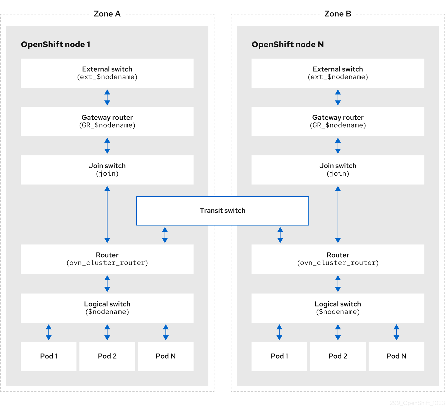
The key components involved in packet processing are:
- Gateway routers
-
Gateway routers sometimes called L3 gateway routers, are typically used between the distributed routers and the physical network. Gateway routers including their logical patch ports are bound to a physical location (not distributed), or chassis. The patch ports on this router are known as l3gateway ports in the ovn-southbound database (
ovn-sbdb). - Distributed logical routers
- Distributed logical routers and the logical switches behind them, to which virtual machines and containers attach, effectively reside on each hypervisor.
- Join local switch
- Join local switches are used to connect the distributed router and gateway routers. It reduces the number of IP addresses needed on the distributed router.
- Logical switches with patch ports
- Logical switches with patch ports are used to virtualize the network stack. They connect remote logical ports through tunnels.
- Logical switches with localnet ports
- Logical switches with localnet ports are used to connect OVN to the physical network. They connect remote logical ports by bridging the packets to directly connected physical L2 segments using localnet ports.
- Patch ports
- Patch ports represent connectivity between logical switches and logical routers and between peer logical routers. A single connection has a pair of patch ports at each such point of connectivity, one on each side.
- l3gateway ports
-
l3gateway ports are the port binding entries in the
ovn-sbdbfor logical patch ports used in the gateway routers. They are called l3gateway ports rather than patch ports just to portray the fact that these ports are bound to a chassis just like the gateway router itself. - localnet ports
-
localnet ports are present on the bridged logical switches that allows a connection to a locally accessible network from each
ovn-controllerinstance. This helps model the direct connectivity to the physical network from the logical switches. A logical switch can only have a single localnet port attached to it.
26.2.7.1. Installing network-tools on local host
Install network-tools on your local host to make a collection of tools available for debugging OpenShift Container Platform cluster network issues.
Procedure
Clone the
network-toolsrepository onto your workstation with the following command:$ git clone git@github.com:openshift/network-tools.gitChange into the directory for the repository you just cloned:
$ cd network-toolsOptional: List all available commands:
$ ./debug-scripts/network-tools -h
26.2.7.2. Running network-tools
Get information about the logical switches and routers by running network-tools.
Prerequisites
-
You installed the OpenShift CLI (
oc). -
You are logged in to the cluster as a user with
cluster-adminprivileges. -
You have installed
network-toolson local host.
Procedure
List the routers by running the following command:
$ ./debug-scripts/network-tools ovn-db-run-command ovn-nbctl lr-listExample output
944a7b53-7948-4ad2-a494-82b55eeccf87 (GR_ci-ln-54932yb-72292-kd676-worker-c-rzj99)
84bd4a4c-4b0b-4a47-b0cf-a2c32709fc53 (ovn_cluster_router)
List the localnet ports by running the following command:
$ ./debug-scripts/network-tools ovn-db-run-command \
ovn-sbctl find Port_Binding type=localnet
Example output
_uuid               : d05298f5-805b-4838-9224-1211afc2f199
additional_chassis  : []
additional_encap    : []
chassis             : []
datapath            : f3c2c959-743b-4037-854d-26627902597c
encap               : []
external_ids        : {}
gateway_chassis     : []
ha_chassis_group    : []
logical_port        : br-ex_ci-ln-54932yb-72292-kd676-worker-c-rzj99
mac                 : [unknown]
mirror_rules        : []
nat_addresses       : []
options             : {network_name=physnet}
parent_port         : []
port_security       : []
requested_additional_chassis: []
requested_chassis   : []
tag                 : []
tunnel_key          : 2
type                : localnet
up                  : false
virtual_parent      : []

[...]
List the
l3gatewayports by running the following command:$ ./debug-scripts/network-tools ovn-db-run-command \ ovn-sbctl find Port_Binding type=l3gatewayExample output
_uuid               : 5207a1f3-1cf3-42f1-83e9-387bbb06b03c
additional_chassis  : []
additional_encap    : []
chassis             : ca6eb600-3a10-4372-a83e-e0d957c4cd92
datapath            : f3c2c959-743b-4037-854d-26627902597c
encap               : []
external_ids        : {}
gateway_chassis     : []
ha_chassis_group    : []
logical_port        : etor-GR_ci-ln-54932yb-72292-kd676-worker-c-rzj99
mac                 : ["42:01:0a:00:80:04"]
mirror_rules        : []
nat_addresses       : ["42:01:0a:00:80:04 10.0.128.4"]
options             : {l3gateway-chassis="84737c36-b383-4c83-92c5-2bd5b3c7e772", peer=rtoe-GR_ci-ln-54932yb-72292-kd676-worker-c-rzj99}
parent_port         : []
port_security       : []
requested_additional_chassis: []
requested_chassis   : []
tag                 : []
tunnel_key          : 1
type                : l3gateway
up                  : true
virtual_parent      : []

_uuid               : 6088d647-84f2-43f2-b53f-c9d379042679
additional_chassis  : []
additional_encap    : []
chassis             : ca6eb600-3a10-4372-a83e-e0d957c4cd92
datapath            : dc9cea00-d94a-41b8-bdb0-89d42d13aa2e
encap               : []
external_ids        : {}
gateway_chassis     : []
ha_chassis_group    : []
logical_port        : jtor-GR_ci-ln-54932yb-72292-kd676-worker-c-rzj99
mac                 : [router]
mirror_rules        : []
nat_addresses       : []
options             : {l3gateway-chassis="84737c36-b383-4c83-92c5-2bd5b3c7e772", peer=rtoj-GR_ci-ln-54932yb-72292-kd676-worker-c-rzj99}
parent_port         : []
port_security       : []
requested_additional_chassis: []
requested_chassis   : []
tag                 : []
tunnel_key          : 2
type                : l3gateway
up                  : true
virtual_parent      : []

[...]
List the patch ports by running the following command:
$ ./debug-scripts/network-tools ovn-db-run-command \
ovn-sbctl find Port_Binding type=patch
Example output
_uuid               : 785fb8b6-ee5a-4792-a415-5b1cb855dac2
additional_chassis  : []
additional_encap    : []
chassis             : []
datapath            : f1ddd1cc-dc0d-43b4-90ca-12651305acec
encap               : []
external_ids        : {}
gateway_chassis     : []
ha_chassis_group    : []
logical_port        : stor-ci-ln-54932yb-72292-kd676-worker-c-rzj99
mac                 : [router]
mirror_rules        : []
nat_addresses       : ["0a:58:0a:80:02:01 10.128.2.1 is_chassis_resident(\"cr-rtos-ci-ln-54932yb-72292-kd676-worker-c-rzj99\")"]
options             : {peer=rtos-ci-ln-54932yb-72292-kd676-worker-c-rzj99}
parent_port         : []
port_security       : []
requested_additional_chassis: []
requested_chassis   : []
tag                 : []
tunnel_key          : 1
type                : patch
up                  : false
virtual_parent      : []

_uuid               : c01ff587-21a5-40b4-8244-4cd0425e5d9a
additional_chassis  : []
additional_encap    : []
chassis             : []
datapath            : f6795586-bf92-4f84-9222-efe4ac6a7734
encap               : []
external_ids        : {}
gateway_chassis     : []
ha_chassis_group    : []
logical_port        : rtoj-ovn_cluster_router
mac                 : ["0a:58:64:40:00:01 100.64.0.1/16"]
mirror_rules        : []
nat_addresses       : []
options             : {peer=jtor-ovn_cluster_router}
parent_port         : []
port_security       : []
requested_additional_chassis: []
requested_chassis   : []
tag                 : []
tunnel_key          : 1
type                : patch
up                  : false
virtual_parent      : []
[...]
26.3. Troubleshooting OVN-Kubernetes
OVN-Kubernetes has many sources of built-in health checks and logs. Follow the instructions in these sections to examine your cluster. If a support case is necessary, follow the support guide to collect additional information through a must-gather. Only use the -- gather_network_logs when instructed by support.
26.3.1. Monitoring OVN-Kubernetes health by using readiness probes
The ovnkube-control-plane and ovnkube-node pods have containers configured with readiness probes.
Prerequisites
-
Access to the OpenShift CLI (
oc). -
You have access to the cluster with
cluster-adminprivileges. -
You have installed
jq.
Procedure
Review the details of the
ovnkube-nodereadiness probe by running the following command:$ oc get pods -n openshift-ovn-kubernetes -l app=ovnkube-node \ -o json | jq '.items[0].spec.containers[] | .name,.readinessProbe'The readiness probe for the northbound and southbound database containers in the
ovnkube-nodepod checks for the health of the databases and theovnkube-controllercontainer.The
ovnkube-controllercontainer in theovnkube-nodepod has a readiness probe to verify the presence of the OVN-Kubernetes CNI configuration file, the absence of which would indicate that the pod is not running or is not ready to accept requests to configure pods.Show all events including the probe failures, for the namespace by using the following command:
$ oc get events -n openshift-ovn-kubernetesShow the events for just a specific pod:
$ oc describe pod ovnkube-node-9lqfk -n openshift-ovn-kubernetesShow the messages and statuses from the cluster network operator:
$ oc get co/network -o json | jq '.status.conditions[]'Show the
readystatus of each container inovnkube-nodepods by running the following script:$ for p in $(oc get pods --selector app=ovnkube-node -n openshift-ovn-kubernetes \ -o jsonpath='{range.items[*]}{" "}{.metadata.name}'); do echo === $p ===; \ oc get pods -n openshift-ovn-kubernetes $p -o json | jq '.status.containerStatuses[] | .name, .ready'; \ doneNoteThe expectation is all container statuses are reporting as
true. Failure of a readiness probe sets the status tofalse.
26.3.2. Viewing OVN-Kubernetes alerts in the console
The Alerting UI provides detailed information about alerts and their governing alerting rules and silences.
Prerequisites
- You have access to the cluster as a developer or as a user with view permissions for the project that you are viewing metrics for.
Procedure (UI)
-
In the Administrator perspective, select Observe
Alerting. The three main pages in the Alerting UI in this perspective are the Alerts, Silences, and Alerting Rules pages. -
View the rules for OVN-Kubernetes alerts by selecting Observe
Alerting Alerting Rules.
26.3.3. Viewing OVN-Kubernetes alerts in the CLI
You can get information about alerts and their governing alerting rules and silences from the command line.
Prerequisites
-
Access to the cluster as a user with the
cluster-adminrole. -
The OpenShift CLI (
oc) installed. -
You have installed
jq.
Procedure
View active or firing alerts by running the following commands.
Set the alert manager route environment variable by running the following command:
$ ALERT_MANAGER=$(oc get route alertmanager-main -n openshift-monitoring \
-o jsonpath='{@.spec.host}')
Issue a
curlrequest to the alert manager route API by running the following command, replacing$ALERT_MANAGERwith the URL of yourAlertmanagerinstance:$ curl -s -k -H "Authorization: Bearer $(oc create token prometheus-k8s -n openshift-monitoring)" https://$ALERT_MANAGER/api/v1/alerts | jq '.data[] | "\(.labels.severity) \(.labels.alertname) \(.labels.pod) \(.labels.container) \(.labels.endpoint) \(.labels.instance)"'
View alerting rules by running the following command:
$ oc -n openshift-monitoring exec -c prometheus prometheus-k8s-0 -- curl -s 'http://localhost:9090/api/v1/rules' | jq '.data.groups[].rules[] | select(((.name|contains("ovn")) or (.name|contains("OVN")) or (.name|contains("Ovn")) or (.name|contains("North")) or (.name|contains("South"))) and .type=="alerting")'
26.3.4. Viewing the OVN-Kubernetes logs using the CLI
You can view the logs for each of the pods in the ovnkube-master and ovnkube-node pods using the OpenShift CLI (oc).
Prerequisites
-
Access to the cluster as a user with the
cluster-adminrole. -
Access to the OpenShift CLI (
oc). -
You have installed
jq.
Procedure
View the log for a specific pod:
$ oc logs -f <pod_name> -c <container_name> -n <namespace>where:
-f- Optional: Specifies that the output follows what is being written into the logs.
<pod_name>- Specifies the name of the pod.
<container_name>- Optional: Specifies the name of a container. When a pod has more than one container, you must specify the container name.
<namespace>- Specify the namespace the pod is running in.
For example:
$ oc logs ovnkube-node-5dx44 -n openshift-ovn-kubernetes$ oc logs -f ovnkube-node-5dx44 -c ovnkube-controller -n openshift-ovn-kubernetesThe contents of log files are printed out.
Examine the most recent entries in all the containers in the
ovnkube-nodepods:$ for p in $(oc get pods --selector app=ovnkube-node -n openshift-ovn-kubernetes \ -o jsonpath='{range.items[*]}{" "}{.metadata.name}'); \ do echo === $p ===; for container in $(oc get pods -n openshift-ovn-kubernetes $p \ -o json | jq -r '.status.containerStatuses[] | .name');do echo ---$container---; \ oc logs -c $container $p -n openshift-ovn-kubernetes --tail=5; done; doneView the last 5 lines of every log in every container in an
ovnkube-nodepod using the following command:$ oc logs -l app=ovnkube-node -n openshift-ovn-kubernetes --all-containers --tail 5
26.3.5. Viewing the OVN-Kubernetes logs using the web console
You can view the logs for each of the pods in the ovnkube-master and ovnkube-node pods in the web console.
Prerequisites
-
Access to the OpenShift CLI (
oc).
Procedure
-
In the OpenShift Container Platform console, navigate to Workloads
Pods or navigate to the pod through the resource you want to investigate. -
Select the
openshift-ovn-kubernetesproject from the drop-down menu. - Click the name of the pod you want to investigate.
-
Click Logs. By default for the
ovnkube-masterthe logs associated with thenorthdcontainer are displayed. - Use the down-down menu to select logs for each container in turn.
26.3.5.1. Changing the OVN-Kubernetes log levels
The default log level for OVN-Kubernetes is 4. To debug OVN-Kubernetes, set the log level to 5. Follow this procedure to increase the log level of the OVN-Kubernetes to help you debug an issue.
Prerequisites
-
You have access to the cluster with
cluster-adminprivileges. - You have access to the OpenShift Container Platform web console.
Procedure
Run the following command to get detailed information for all pods in the OVN-Kubernetes project:
$ oc get po -o wide -n openshift-ovn-kubernetesExample output
NAME                                     READY   STATUS    RESTARTS       AGE    IP           NODE                                       NOMINATED NODE   READINESS GATES
ovnkube-control-plane-65497d4548-9ptdr   2/2     Running   2 (128m ago)   147m   10.0.0.3     ci-ln-3njdr9b-72292-5nwkp-master-0         <none>           <none>
ovnkube-control-plane-65497d4548-j6zfk   2/2     Running   0              147m   10.0.0.5     ci-ln-3njdr9b-72292-5nwkp-master-2         <none>           <none>
ovnkube-node-5dx44                       8/8     Running   0              146m   10.0.0.3     ci-ln-3njdr9b-72292-5nwkp-master-0         <none>           <none>
ovnkube-node-dpfn4                       8/8     Running   0              146m   10.0.0.4     ci-ln-3njdr9b-72292-5nwkp-master-1         <none>           <none>
ovnkube-node-kwc9l                       8/8     Running   0              134m   10.0.128.2   ci-ln-3njdr9b-72292-5nwkp-worker-a-2fjcj   <none>           <none>
ovnkube-node-mcrhl                       8/8     Running   0              134m   10.0.128.4   ci-ln-3njdr9b-72292-5nwkp-worker-c-v9x5v   <none>           <none>
ovnkube-node-nsct4                       8/8     Running   0              146m   10.0.0.5     ci-ln-3njdr9b-72292-5nwkp-master-2         <none>           <none>
ovnkube-node-zrj9f                       8/8     Running   0              134m   10.0.128.3   ci-ln-3njdr9b-72292-5nwkp-worker-b-v78h7   <none>           <none>
Create a
ConfigMapfile similar to the following example and use a filename such asenv-overrides.yaml:Example
ConfigMapfilekind: ConfigMap apiVersion: v1 metadata: name: env-overrides namespace: openshift-ovn-kubernetes data: ci-ln-3njdr9b-72292-5nwkp-master-0: |1 # This sets the log level for the ovn-kubernetes node process: OVN_KUBE_LOG_LEVEL=5 # You might also/instead want to enable debug logging for ovn-controller: OVN_LOG_LEVEL=dbg ci-ln-3njdr9b-72292-5nwkp-master-2: | # This sets the log level for the ovn-kubernetes node process: OVN_KUBE_LOG_LEVEL=5 # You might also/instead want to enable debug logging for ovn-controller: OVN_LOG_LEVEL=dbg _master: |2 # This sets the log level for the ovn-kubernetes master process as well as the ovn-dbchecker: OVN_KUBE_LOG_LEVEL=5 # You might also/instead want to enable debug logging for northd, nbdb and sbdb on all masters: OVN_LOG_LEVEL=dbgApply the
ConfigMapfile by using the following command:$ oc apply -n openshift-ovn-kubernetes -f env-overrides.yamlExample output
configmap/env-overrides.yaml createdRestart the
ovnkubepods to apply the new log level by using the following commands:$ oc delete pod -n openshift-ovn-kubernetes \ --field-selector spec.nodeName=ci-ln-3njdr9b-72292-5nwkp-master-0 -l app=ovnkube-node$ oc delete pod -n openshift-ovn-kubernetes \ --field-selector spec.nodeName=ci-ln-3njdr9b-72292-5nwkp-master-2 -l app=ovnkube-node$ oc delete pod -n openshift-ovn-kubernetes -l app=ovnkube-nodeTo verify that the `ConfigMap`file has been applied to all nodes for a specific pod, run the following command:
$ oc logs -n openshift-ovn-kubernetes --all-containers --prefix ovnkube-node-<xxxx> | grep -E -m 10 '(Logging config:|vconsole|DBG)'where:
<XXXX>Specifies the random sequence of letters for a pod from the previous step.
Example output
[pod/ovnkube-node-2cpjc/sbdb] + exec /usr/share/ovn/scripts/ovn-ctl --no-monitor '--ovn-sb-log=-vconsole:info -vfile:off -vPATTERN:console:%D{%Y-%m-%dT%H:%M:%S.###Z}|%05N|%c%T|%p|%m' run_sb_ovsdb
[pod/ovnkube-node-2cpjc/ovnkube-controller] I1012 14:39:59.984506   35767 config.go:2247] Logging config: {File: CNIFile:/var/log/ovn-kubernetes/ovn-k8s-cni-overlay.log LibovsdbFile:/var/log/ovnkube/libovsdb.log Level:5 LogFileMaxSize:100 LogFileMaxBackups:5 LogFileMaxAge:0 ACLLoggingRateLimit:20}
[pod/ovnkube-node-2cpjc/northd] + exec ovn-northd --no-chdir -vconsole:info -vfile:off '-vPATTERN:console:%D{%Y-%m-%dT%H:%M:%S.###Z}|%05N|%c%T|%p|%m' --pidfile /var/run/ovn/ovn-northd.pid --n-threads=1
[pod/ovnkube-node-2cpjc/nbdb] + exec /usr/share/ovn/scripts/ovn-ctl --no-monitor '--ovn-nb-log=-vconsole:info -vfile:off -vPATTERN:console:%D{%Y-%m-%dT%H:%M:%S.###Z}|%05N|%c%T|%p|%m' run_nb_ovsdb
[pod/ovnkube-node-2cpjc/ovn-controller] 2023-10-12T14:39:54.552Z|00002|hmap|DBG|lib/shash.c:114: 1 bucket with 6+ nodes, including 1 bucket with 6 nodes (32 nodes total across 32 buckets)
[pod/ovnkube-node-2cpjc/ovn-controller] 2023-10-12T14:39:54.553Z|00003|hmap|DBG|lib/shash.c:114: 1 bucket with 6+ nodes, including 1 bucket with 6 nodes (64 nodes total across 64 buckets)
[pod/ovnkube-node-2cpjc/ovn-controller] 2023-10-12T14:39:54.553Z|00004|hmap|DBG|lib/shash.c:114: 1 bucket with 6+ nodes, including 1 bucket with 7 nodes (32 nodes total across 32 buckets)
[pod/ovnkube-node-2cpjc/ovn-controller] 2023-10-12T14:39:54.553Z|00005|reconnect|DBG|unix:/var/run/openvswitch/db.sock: entering BACKOFF
[pod/ovnkube-node-2cpjc/ovn-controller] 2023-10-12T14:39:54.553Z|00007|reconnect|DBG|unix:/var/run/openvswitch/db.sock: entering CONNECTING
[pod/ovnkube-node-2cpjc/ovn-controller] 2023-10-12T14:39:54.553Z|00008|ovsdb_cs|DBG|unix:/var/run/openvswitch/db.sock: SERVER_SCHEMA_REQUESTED -> SERVER_SCHEMA_REQUESTED at lib/ovsdb-cs.c:423
Optional: Check the
ConfigMapfile has been applied by running the following command:for f in $(oc -n openshift-ovn-kubernetes get po -l 'app=ovnkube-node' --no-headers -o custom-columns=N:.metadata.name) ; do echo "---- $f ----" ; oc -n openshift-ovn-kubernetes exec -c ovnkube-controller $f -- pgrep -a -f init-ovnkube-controller | grep -P -o '^.*loglevel\s+\d' ; doneExample output
---- ovnkube-node-2dt57 ----
60981 /usr/bin/ovnkube --init-ovnkube-controller xpst8-worker-c-vmh5n.c.openshift-qe.internal --init-node xpst8-worker-c-vmh5n.c.openshift-qe.internal --config-file=/run/ovnkube-config/ovnkube.conf --ovn-empty-lb-events --loglevel 4
---- ovnkube-node-4zznh ----
178034 /usr/bin/ovnkube --init-ovnkube-controller xpst8-master-2.c.openshift-qe.internal --init-node xpst8-master-2.c.openshift-qe.internal --config-file=/run/ovnkube-config/ovnkube.conf --ovn-empty-lb-events --loglevel 4
---- ovnkube-node-548sx ----
77499 /usr/bin/ovnkube --init-ovnkube-controller xpst8-worker-a-fjtnb.c.openshift-qe.internal --init-node xpst8-worker-a-fjtnb.c.openshift-qe.internal --config-file=/run/ovnkube-config/ovnkube.conf --ovn-empty-lb-events --loglevel 4
---- ovnkube-node-6btrf ----
73781 /usr/bin/ovnkube --init-ovnkube-controller xpst8-worker-b-p8rww.c.openshift-qe.internal --init-node xpst8-worker-b-p8rww.c.openshift-qe.internal --config-file=/run/ovnkube-config/ovnkube.conf --ovn-empty-lb-events --loglevel 4
---- ovnkube-node-fkc9r ----
130707 /usr/bin/ovnkube --init-ovnkube-controller xpst8-master-0.c.openshift-qe.internal --init-node xpst8-master-0.c.openshift-qe.internal --config-file=/run/ovnkube-config/ovnkube.conf --ovn-empty-lb-events --loglevel 5
---- ovnkube-node-tk9l4 ----
181328 /usr/bin/ovnkube --init-ovnkube-controller xpst8-master-1.c.openshift-qe.internal --init-node xpst8-master-1.c.openshift-qe.internal --config-file=/run/ovnkube-config/ovnkube.conf --ovn-empty-lb-events --loglevel 4
26.3.6. Checking the OVN-Kubernetes pod network connectivity
The connectivity check controller, in OpenShift Container Platform 4.10 and later, orchestrates connection verification checks in your cluster. These include Kubernetes API, OpenShift API and individual nodes. The results for the connection tests are stored in PodNetworkConnectivity objects in the openshift-network-diagnostics namespace. Connection tests are performed every minute in parallel.
Prerequisites
-
Access to the OpenShift CLI (
oc). -
Access to the cluster as a user with the
cluster-adminrole. -
You have installed
jq.
Procedure
To list the current
PodNetworkConnectivityCheckobjects, enter the following command:$ oc get podnetworkconnectivitychecks -n openshift-network-diagnosticsView the most recent success for each connection object by using the following command:
$ oc get podnetworkconnectivitychecks -n openshift-network-diagnostics \
-o json | jq '.items[]| .spec.targetEndpoint,.status.successes[0]'
View the most recent failures for each connection object by using the following command:
$ oc get podnetworkconnectivitychecks -n openshift-network-diagnostics \
-o json | jq '.items[]| .spec.targetEndpoint,.status.failures[0]'
View the most recent outages for each connection object by using the following command:
$ oc get podnetworkconnectivitychecks -n openshift-network-diagnostics \
-o json | jq '.items[]| .spec.targetEndpoint,.status.outages[0]'
The connectivity check controller also logs metrics from these checks into Prometheus.
View all the metrics by running the following command:
$ oc exec prometheus-k8s-0 -n openshift-monitoring -- \
promtool query instant  http://localhost:9090 \
'{component="openshift-network-diagnostics"}'
View the latency between the source pod and the openshift api service for the last 5 minutes:
$ oc exec prometheus-k8s-0 -n openshift-monitoring -- \
promtool query instant  http://localhost:9090 \
'{component="openshift-network-diagnostics"}'
26.4. OVN-Kubernetes network policy
The AdminNetworkPolicy resource is a Technology Preview feature only. Technology Preview features are not supported with Red Hat production service level agreements (SLAs) and might not be functionally complete. Red Hat does not recommend using them in production. These features provide early access to upcoming product features, enabling customers to test functionality and provide feedback during the development process.
For more information about the support scope of Red Hat Technology Preview features, see Technology Preview Features Support Scope.
Kubernetes offers two features that users can use to enforce network security. One feature that allows users to enforce network policy is the NetworkPolicy API that is designed mainly for application developers and namespace tenants to protect their namespaces by creating namespace-scoped policies. For more information, see About network policy.
The second feature is AdminNetworkPolicy which is comprised of two API: the AdminNetworkPolicy (ANP) API and the BaselineAdminNetworkPolicy (BANP) API. ANP and BANP are designed for cluster and network administrators to protect their entire cluster by creating cluster-scoped policies. Cluster administrators can use ANPs to enforce non-overridable policies that take precedence over NetworkPolicy objects. Administrators can use BANP to setup and enforce optional cluster-scoped network policy rules that are overridable by users using NetworkPolicy objects if need be. When used together ANP and BANP can create multi-tenancy policy that administrators can use to secure their cluster.
OVN-Kubernetes CNI in OpenShift Container Platform implements these network policies using Access Control List (ACLs) Tiers to evaluate and apply them. ACLs are evaluated in descending order from Tier 1 to Tier 3.
Tier 1 evaluates AdminNetworkPolicy (ANP) objects. Tier 2 evaluates NetworkPolicy objects. Tier 3 evaluates BaselineAdminNetworkPolicy (BANP) objects.
Figure 26.3. OVK-Kubernetes Access Control List (ACL)
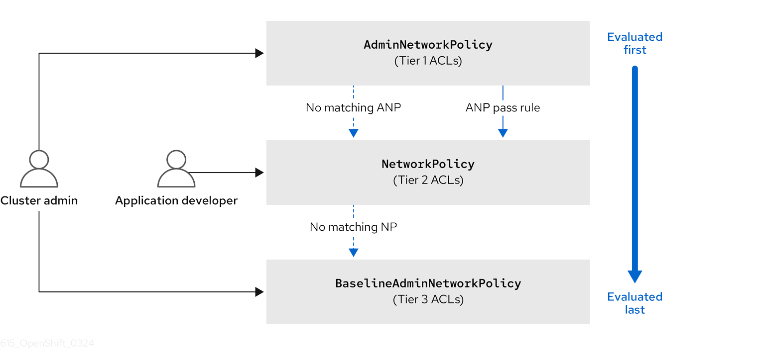
If traffic matches an ANP rule, the rules in that ANP will be evaluated first. If the match is an ANP allow or deny rule, any existing NetworkPolicies and BaselineAdminNetworkPolicy (BANP) in the cluster will be intentionally skipped from evaluation. If the match is an ANP pass rule, then evaluation moves from tier 1 of the ACLs to tier 2 where the NetworkPolicy policy is evaluated.
26.4.1. AdminNetworkPolicy
An AdminNetworkPolicy (ANP) is a cluster-scoped custom resource definition (CRD). As a OpenShift Container Platform administrator, you can use ANP to secure your network by creating network policies before creating namespaces. Additionally, you can create network policies on a cluster-scoped level that is non-overridable by NetworkPolicy objects.
The key difference between AdminNetworkPolicy and NetworkPolicy objects are that the former is for administrators and is cluster scoped while the latter is for tenant owners and is namespace scoped.
An ANP allows administrators to specify the following:
-
A
priorityvalue that determines the order of its evaluation. The lower the value the higher the precedence. -
A
subjectthat consists of a set of namespaces or namespace.. -
A list of ingress rules to be applied for all ingress traffic towards the
subject. -
A list of egress rules to be applied for all egress traffic from the
subject.
The AdminNetworkPolicy resource is a TechnologyPreviewNoUpgrade feature that can be enabled on test clusters that are not in production. For more information on feature gates and TechnologyPreviewNoUpgrade features, see "Enabling features using feature gates" in the "Additional resources" of this section.
26.4.1.1. AdminNetworkPolicy example
Example 26.1. Example YAML file for an ANP
apiVersion: policy.networking.k8s.io/v1alpha1
kind: AdminNetworkPolicy
metadata:
  name: sample-anp-deny-pass-rules
spec:
  priority: 50
  subject:
    namespaces:
      matchLabels:
          kubernetes.io/metadata.name: example.name
ingress:
- name: "deny-all-ingress-tenant-1"
    action: "Deny"
    from:
    - pods:
        namespaces:
          namespaceSelector:
            matchLabels:
              custom-anp: tenant-1
        podSelector:
          matchLabels:
            custom-anp: tenant-1
egress:
  - name: "pass-all-egress-to-tenant-1"
    action: "Pass"
    to:
    - pods:
        namespaces:
          namespaceSelector:
            matchLabels:
              custom-anp: tenant-1
        podSelector:
          matchLabels:
custom-anp: tenant-1- 1
- Specify a name for your ANP.
- 2
- The
spec.priorityfield supports a maximum of 100 ANP in the values of 0-99 in a cluster. The lower the value the higher the precedence. CreatingAdminNetworkPolicywith the same priority creates a nondeterministic outcome. - 3
- Specify the namespace to apply the ANP resource.
- 4
- ANP have both ingress and egress rules. ANP rules for
spec.ingressfield accepts values ofPass,Deny, andAllowfor theactionfield. - 5
- Specify a name for the
ingress.name. - 6
- Specify the namespaces to select the pods from to apply the ANP resource.
- 7
- Specify
podSelector.matchLabelsname of the pods to apply the ANP resource. - 8
- ANP have both ingress and egress rules. ANP rules for
spec.egressfield accepts values ofPass,Deny, andAllowfor theactionfield.
Additional resources
26.4.1.2. AdminNetworkPolicy actions for rules
As an administrator, you can set Allow, Deny, or Pass as the action field for your AdminNetworkPolicy rules. Because OVN-Kubernetes uses a tiered ACLs to evaluate network traffic rules, ANP allow you to set very strong policy rules that can only be changed by an administrator modifying them, deleting the rule, or overriding them by setting a higher priority rule.
26.4.1.2.1. AdminNetworkPolicy Allow example
The following ANP that is defined at priority 9 ensures all ingress traffic is allowed from the monitoring namespace towards any tenant (all other namespaces) in the cluster.
Example 26.2. Example YAML file for a strong Allow ANP
apiVersion: policy.networking.k8s.io/v1alpha1
kind: AdminNetworkPolicy
metadata:
  name: allow-monitoring
spec:
  priority: 9
  subject:
    namespaces: {}
  ingress:
  - name: "allow-ingress-from-monitoring"
    action: "Allow"
    from:
    - namespaces:
        namespaceSelector:
          matchLabels:
            kubernetes.io/metadata.name: monitoring
# ...
This is an example of a strong Allow ANP because it is non-overridable by all the parties involved. No tenants can block themselves from being monitored using NetworkPolicy objects and the monitoring tenant also has no say in what it can or cannot monitor.
26.4.1.2.2. AdminNetworkPolicy Deny example
The following ANP that is defined at priority 5 ensures all ingress traffic from the monitoring namespace is blocked towards restricted tenants (namespaces that have labels security: restricted).
Example 26.3. Example YAML file for a strong Deny ANP
apiVersion: policy.networking.k8s.io/v1alpha1
kind: AdminNetworkPolicy
metadata:
  name: block-monitoring
spec:
  priority: 5
  subject:
    namespaces:
      matchLabels:
        security: restricted
  ingress:
  - name: "deny-ingress-from-monitoring"
    action: "Deny"
    from:
    - namespaces:
        namespaceSelector:
          matchLabels:
            kubernetes.io/metadata.name: monitoring
# ...
This is a strong Deny ANP that is non-overridable by all the parties involved. The restricted tenant owners cannot authorize themselves to allow monitoring traffic, and the infrastructure’s monitoring service cannot scrape anything from these sensitive namespaces.
When combined with the strong Allow example, the block-monitoring ANP has a lower priority value giving it higher precedence, which ensures restricted tenants are never monitored.
26.4.1.2.3. AdminNetworkPolicy Pass example
TThe following ANP that is defined at priority 7 ensures all ingress traffic from the monitoring namespace towards internal infrastructure tenants (namespaces that have labels security: internal) are passed on to tier 2 of the ACLs and evaluated by the namespaces’ NetworkPolicy objects.
Example 26.4. Example YAML file for a strong Pass ANP
apiVersion: policy.networking.k8s.io/v1alpha1
kind: AdminNetworkPolicy
metadata:
  name: pass-monitoring
spec:
  priority: 7
  subject:
    namespaces:
      matchLabels:
        security: internal
  ingress:
  - name: "pass-ingress-from-monitoring"
    action: "Pass"
    from:
    - namespaces:
        namespaceSelector:
          matchLabels:
            kubernetes.io/metadata.name: monitoring
# ...
This example is a strong Pass action ANP because it delegates the decision to NetworkPolicy objects defined by tenant owners. This pass-monitoring ANP allows all tenant owners grouped at security level internal to choose if their metrics should be scraped by the infrastructures' monitoring service using namespace scoped NetworkPolicy objects.
26.4.2. BaselineAdminNetworkPolicy
BaselineAdminNetworkPolicy (BANP) is a cluster-scoped custom resource definition (CRD). As a OpenShift Container Platform administrator, you can use BANP to setup and enforce optional baseline network policy rules that are overridable by users using NetworkPolicy objects if need be. Rule actions for BANP are allow or deny.
The BaselineAdminNetworkPolicy resource is a cluster singleton object that can be used as a guardrail policy incase a passed traffic policy does not match any NetworkPolicy objects in the cluster. A BANP can also be used as a default security model that provides guardrails that intra-cluster traffic is blocked by default and a user will need to use NetworkPolicy objects to allow known traffic. You must use default as the name when creating a BANP resource.
A BANP allows administrators to specify:
-
A
subjectthat consists of a set of namespaces or namespace. -
A list of ingress rules to be applied for all ingress traffic towards the
subject. -
A list of egress rules to be applied for all egress traffic from the
subject.
BaselineAdminNetworkPolicy is a TechnologyPreviewNoUpgrade feature that can be enabled on test clusters that are not in production.
26.4.2.1. BaselineAdminNetworkPolicy example
Example 26.5. Example YAML file for BANP
apiVersion: policy.networking.k8s.io/v1alpha1
kind: BaselineAdminNetworkPolicy
metadata:
  name: default
spec:
  subject:
    namespaces:
      matchLabels:
          kubernetes.io/metadata.name: example.name
ingress:
- name: "deny-all-ingress-from-tenant-1"
    action: "Deny"
    from:
    - pods:
        namespaces:
          namespaceSelector:
            matchLabels:
              custom-banp: tenant-1
        podSelector:
          matchLabels:
            custom-banp: tenant-1
  egress:
  - name: "allow-all-egress-to-tenant-1"
    action: "Allow"
    to:
    - pods:
        namespaces:
          namespaceSelector:
            matchLabels:
              custom-banp: tenant-1
        podSelector:
          matchLabels:
custom-banp: tenant-1- 1
- The policy name must be
defaultbecause BANP is a singleton object. - 2
- Specify the namespace to apply the ANP to.
- 3
- BANP have both ingress and egress rules. BANP rules for
spec.ingressandspec.egressfields accepts values ofDenyandAllowfor theactionfield. - 4
- Specify a name for the
ingress.name - 5
- Specify the namespaces to select the pods from to apply the BANP resource.
- 6
- Specify
podSelector.matchLabelsname of the pods to apply the BANP resource.
26.4.2.2. BaselineAdminNetworkPolicy Deny example
The following BANP singleton ensures that the administrator has set up a default deny policy for all ingress monitoring traffic coming into the tenants at internal security level. When combined with the "AdminNetworkPolicy Pass example", this deny policy acts as a guardrail policy for all ingress traffic that is passed by the ANP pass-monitoring policy.
Example 26.6. Example YAML file for a guardrail Deny rule
apiVersion: policy.networking.k8s.io/v1alpha1
kind: BaselineAdminNetworkPolicy
metadata:
  name: default
spec:
  subject:
    namespaces:
      matchLabels:
        security: internal
  ingress:
  - name: "deny-ingress-from-monitoring"
    action: "Deny"
    from:
    - namespaces:
        namespaceSelector:
          matchLabels:
            kubernetes.io/metadata.name: monitoring
# ...
You can use an AdminNetworkPolicy resource with a Pass value for the action field in conjunction with the BaselineAdminNetworkPolicy resource to create a multi-tenant policy. This multi-tenant policy allows one tenant to collect monitoring data on their application while simultaneously not collecting data from a second tenant.
As an administrator, if you apply both the "AdminNetworkPolicy Pass action example" and the "BaselineAdminNetwork Policy Deny example", tenants are then left with the ability to choose to create a NetworkPolicy resource that will be evaluated before the BANP.
For example, Tenant 1 can set up the following NetworkPolicy resource to monitor ingress traffic:
Example 26.7. Example NetworkPolicy
apiVersion: networking.k8s.io/v1
kind: NetworkPolicy
metadata:
  name: allow-monitoring
  namespace: tenant 1
spec:
  podSelector:
  policyTypes:
    - Ingress
  ingress:
  - from:
    - namespaceSelector:
        matchLabels:
          kubernetes.io/metadata.name: monitoring
# ...
In this scenario, Tenant 1’s policy would be evaluated after the "AdminNetworkPolicy Pass action example" and before the "BaselineAdminNetwork Policy Deny example", which denies all ingress monitoring traffic coming into tenants with security level internal. With Tenant 1’s NetworkPolicy object in place, they will be able to collect data on their application. Tenant 2, however, who does not have any NetworkPolicy objects in place, will not be able to collect data. As an administrator, you have not by default monitored internal tenants, but instead, you created a BANP that allows tenants to use NetworkPolicy objects to override the default behavior of your BANP.
26.5. Tracing Openflow with ovnkube-trace
OVN and OVS traffic flows can be simulated in a single utility called ovnkube-trace. The ovnkube-trace utility runs ovn-trace, ovs-appctl ofproto/trace and ovn-detrace and correlates that information in a single output.
You can execute the ovnkube-trace binary from a dedicated container. For releases after OpenShift Container Platform 4.7, you can also copy the binary to a local host and execute it from that host.
26.5.1. Installing the ovnkube-trace on local host
The ovnkube-trace tool traces packet simulations for arbitrary UDP or TCP traffic between points in an OVN-Kubernetes driven OpenShift Container Platform cluster. Copy the ovnkube-trace binary to your local host making it available to run against the cluster.
Prerequisites
-
You installed the OpenShift CLI (
oc). -
You are logged in to the cluster with a user with
cluster-adminprivileges.
Procedure
Create a pod variable by using the following command:
$ POD=$(oc get pods -n openshift-ovn-kubernetes -l app=ovnkube-control-plane -o name | head -1 | awk -F '/' '{print $NF}')Run the following command on your local host to copy the binary from the
ovnkube-control-planepods:$ oc cp -n openshift-ovn-kubernetes $POD:/usr/bin/ovnkube-trace -c ovnkube-cluster-manager ovnkube-traceNoteIf you are using Red Hat Enterprise Linux (RHEL) 8 to run the
ovnkube-tracetool, you must copy the file/usr/lib/rhel8/ovnkube-traceto your local host.Make
ovnkube-traceexecutable by running the following command:$ chmod +x ovnkube-traceDisplay the options available with
ovnkube-traceby running the following command:$ ./ovnkube-trace -helpExpected output
Usage of ./ovnkube-trace:
  -addr-family string
    	Address family (ip4 or ip6) to be used for tracing (default "ip4")
  -dst string
    	dest: destination pod name
  -dst-ip string
    	destination IP address (meant for tests to external targets)
  -dst-namespace string
    	k8s namespace of dest pod (default "default")
  -dst-port string
    	dst-port: destination port (default "80")
  -kubeconfig string
    	absolute path to the kubeconfig file
  -loglevel string
    	loglevel: klog level (default "0")
  -ovn-config-namespace string
    	namespace used by ovn-config itself
  -service string
    	service: destination service name
  -skip-detrace
    	skip ovn-detrace command
  -src string
    	src: source pod name
  -src-namespace string
    	k8s namespace of source pod (default "default")
  -tcp
    	use tcp transport protocol
  -udp
    	use udp transport protocol
The command-line arguments supported are familiar Kubernetes constructs, such as namespaces, pods, services so you do not need to find the MAC address, the IP address of the destination nodes, or the ICMP type.
The log levels are:
- 0 (minimal output)
- 2 (more verbose output showing results of trace commands)
- 5 (debug output)
26.5.2. Running ovnkube-trace
Run ovn-trace to simulate packet forwarding within an OVN logical network.
Prerequisites
-
You installed the OpenShift CLI (
oc). -
You are logged in to the cluster with a user with
cluster-adminprivileges. -
You have installed
ovnkube-traceon local host
Example: Testing that DNS resolution works from a deployed pod
This example illustrates how to test the DNS resolution from a deployed pod to the core DNS pod that runs in the cluster.
Procedure
Start a web service in the default namespace by entering the following command:
$ oc run web --namespace=default --image=quay.io/openshifttest/nginx --labels="app=web" --expose --port=80List the pods running in the
openshift-dnsnamespace:oc get pods -n openshift-dnsExample output
NAME                  READY   STATUS    RESTARTS   AGE
dns-default-8s42x     2/2     Running   0          5h8m
dns-default-mdw6r     2/2     Running   0          4h58m
dns-default-p8t5h     2/2     Running   0          4h58m
dns-default-rl6nk     2/2     Running   0          5h8m
dns-default-xbgqx     2/2     Running   0          5h8m
dns-default-zv8f6     2/2     Running   0          4h58m
node-resolver-62jjb   1/1     Running   0          5h8m
node-resolver-8z4cj   1/1     Running   0          4h59m
node-resolver-bq244   1/1     Running   0          5h8m
node-resolver-hc58n   1/1     Running   0          4h59m
node-resolver-lm6z4   1/1     Running   0          5h8m
node-resolver-zfx5k   1/1     Running   0          5h
Run the following
ovnkube-tracecommand to verify DNS resolution is working:$ ./ovnkube-trace \ -src-namespace default \1 -src web \2 -dst-namespace openshift-dns \3 -dst dns-default-p8t5h \4 -udp -dst-port 53 \5 -loglevel 06 Example output if the
src&dstpod lands on the same node:ovn-trace source pod to destination pod indicates success from web to dns-default-p8t5h ovn-trace destination pod to source pod indicates success from dns-default-p8t5h to web ovs-appctl ofproto/trace source pod to destination pod indicates success from web to dns-default-p8t5h ovs-appctl ofproto/trace destination pod to source pod indicates success from dns-default-p8t5h to web ovn-detrace source pod to destination pod indicates success from web to dns-default-p8t5h ovn-detrace destination pod to source pod indicates success from dns-default-p8t5h to webExample output if the
src&dstpod lands on a different node:ovn-trace source pod to destination pod indicates success from web to dns-default-8s42x ovn-trace (remote) source pod to destination pod indicates success from web to dns-default-8s42x ovn-trace destination pod to source pod indicates success from dns-default-8s42x to web ovn-trace (remote) destination pod to source pod indicates success from dns-default-8s42x to web ovs-appctl ofproto/trace source pod to destination pod indicates success from web to dns-default-8s42x ovs-appctl ofproto/trace destination pod to source pod indicates success from dns-default-8s42x to web ovn-detrace source pod to destination pod indicates success from web to dns-default-8s42x ovn-detrace destination pod to source pod indicates success from dns-default-8s42x to webThe ouput indicates success from the deployed pod to the DNS port and also indicates that it is successful going back in the other direction. So you know bi-directional traffic is supported on UDP port 53 if my web pod wants to do dns resolution from core DNS.
If for example that did not work and you wanted to get the ovn-trace, the ovs-appctl of proto/trace and ovn-detrace, and more debug type information increase the log level to 2 and run the command again as follows:
$ ./ovnkube-trace \
  -src-namespace default \
-src web \
-dst-namespace openshift-dns \
-dst dns-default-467qw \
-udp -dst-port 53 \
-loglevel 2The output from this increased log level is too much to list here. In a failure situation the output of this command shows which flow is dropping that traffic. For example an egress or ingress network policy may be configured on the cluster that does not allow that traffic.
Example: Verifying by using debug output a configured default deny
This example illustrates how to identify by using the debug output that an ingress default deny policy blocks traffic.
Procedure
Create the following YAML that defines a
deny-by-defaultpolicy to deny ingress from all pods in all namespaces. Save the YAML in thedeny-by-default.yamlfile:kind: NetworkPolicy apiVersion: networking.k8s.io/v1 metadata: name: deny-by-default namespace: default spec: podSelector: {} ingress: []Apply the policy by entering the following command:
$ oc apply -f deny-by-default.yamlExample output
networkpolicy.networking.k8s.io/deny-by-default createdStart a web service in the
defaultnamespace by entering the following command:$ oc run web --namespace=default --image=quay.io/openshifttest/nginx --labels="app=web" --expose --port=80Run the following command to create the
prodnamespace:$ oc create namespace prodRun the following command to label the
prodnamespace:$ oc label namespace/prod purpose=productionRun the following command to deploy an
alpineimage in theprodnamespace and start a shell:$ oc run test-6459 --namespace=prod --rm -i -t --image=alpine -- sh- Open another terminal session.
In this new terminal session run
ovn-traceto verify the failure in communication between the source podtest-6459running in namespaceprodand destination pod running in thedefaultnamespace:$ ./ovnkube-trace \ -src-namespace prod \ -src test-6459 \ -dst-namespace default \ -dst web \ -tcp -dst-port 80 \ -loglevel 0Example output
ovn-trace source pod to destination pod indicates failure from test-6459 to webIncrease the log level to 2 to expose the reason for the failure by running the following command:
$ ./ovnkube-trace \
 -src-namespace prod \
 -src test-6459 \
 -dst-namespace default \
 -dst web \
 -tcp -dst-port 80 \
 -loglevel 2
Example output
...
------------------------------------------------
 3. ls_out_acl_hint (northd.c:7454): !ct.new && ct.est && !ct.rpl && ct_mark.blocked == 0, priority 4, uuid 12efc456
    reg0[8] = 1;
    reg0[10] = 1;
    next;
 5. ls_out_acl_action (northd.c:7835): reg8[30..31] == 0, priority 500, uuid 69372c5d
    reg8[30..31] = 1;
    next(4);
 5. ls_out_acl_action (northd.c:7835): reg8[30..31] == 1, priority 500, uuid 2fa0af89
    reg8[30..31] = 2;
    next(4);
 4. ls_out_acl_eval (northd.c:7691): reg8[30..31] == 2 && reg0[10] == 1 && (outport == @a16982411286042166782_ingressDefaultDeny), priority 2000, uuid 447d0dab
    reg8[17] = 1;
    ct_commit { ct_mark.blocked = 1; };
1 next; ...- 1
- Ingress traffic is blocked due to the default deny policy being in place.
Create a policy that allows traffic from all pods in a particular namespaces with a label
purpose=production. Save the YAML in theweb-allow-prod.yamlfile:kind: NetworkPolicy apiVersion: networking.k8s.io/v1 metadata: name: web-allow-prod namespace: default spec: podSelector: matchLabels: app: web policyTypes: - Ingress ingress: - from: - namespaceSelector: matchLabels: purpose: productionApply the policy by entering the following command:
$ oc apply -f web-allow-prod.yamlRun
ovnkube-traceto verify that traffic is now allowed by entering the following command:$ ./ovnkube-trace \ -src-namespace prod \ -src test-6459 \ -dst-namespace default \ -dst web \ -tcp -dst-port 80 \ -loglevel 0Expected output
ovn-trace source pod to destination pod indicates success from test-6459 to web
ovn-trace destination pod to source pod indicates success from web to test-6459
ovs-appctl ofproto/trace source pod to destination pod indicates success from test-6459 to web
ovs-appctl ofproto/trace destination pod to source pod indicates success from web to test-6459
ovn-detrace source pod to destination pod indicates success from test-6459 to web
ovn-detrace destination pod to source pod indicates success from web to test-6459
Run the following command in the shell that was opened in step six to connect nginx to the web-server:
wget -qO- --timeout=2 http://web.defaultExpected output
<!DOCTYPE html>
<html>
<head>
<title>Welcome to nginx!</title>
<style>
  body {
    width: 35em;
    margin: 0 auto;
    font-family: Tahoma, Verdana, Arial, sans-serif;
  }
</style>
</head>
<body>
<h1>Welcome to nginx!</h1>
<p>If you see this page, the nginx web server is successfully installed and
working. Further configuration is required.</p>

<p>For online documentation and support please refer to
<a href="http://nginx.org/">nginx.org</a>.<br/>
Commercial support is available at
<a href="http://nginx.com/">nginx.com</a>.</p>

<p><em>Thank you for using nginx.</em></p>
</body>
</html>
26.6. Migrating from the OpenShift SDN network plugin
As a cluster administrator, you can migrate to the OVN-Kubernetes network plugin from the OpenShift software-defined networking (SDN) plugin.
The following methods exist for migrating from the OpenShift SDN network plugin to the OVN-Kubernetes plugin:
- Ansible playbook
- The Ansible playbook method automates the offline migration method steps. This method has the same usage scenarios as the manual offline migration method.
- Offline migration
- This is a manual process that includes some downtime. This method is primarily used for self-managed OpenShift Container Platform deployments, and consider using this method when you cannot perform a limited live migration to the OVN-Kubernetes network plugin.
- Limited live migration (Preferred method)
- This is an automated process that migrates your cluster from OpenShift SDN to OVN-Kubernetes.
For the limited live migration method only, do not automate the migration from OpenShift SDN to OVN-Kubernetes with a script or another tool such as Red Hat Ansible Automation Platform. This might cause outages or crash your OpenShift Container Platform cluster.
26.6.1. Limited live migration to the OVN-Kubernetes network plugin overview
The limited live migration method is the process in which the OpenShift SDN network plugin and its network configurations, connections, and associated resources, are migrated to the OVN-Kubernetes network plugin without service interruption. For OpenShift Container Platform 4.15, it is available for versions 4.15.31 and later. It is the preferred method for migrating from OpenShift SDN to OVN-Kubernetes. In the event that you cannot perform a limited live migration, you can use the offline migration method.
Before you migrate your OpenShift Container Platform cluster to use the OVN-Kubernetes network plugin, update your cluster to the latest z-stream release so that all the latest bug fixes apply to your cluster.
It is not available for hosted control plane deployment types. This migration method is valuable for deployment types that require constant service availability and offers the following benefits:
- Continuous service availability
- Minimized downtime
- Automatic node rebooting
- Seamless transition from the OpenShift SDN network plugin to the OVN-Kubernetes network plugin
Although a rollback procedure is provided, the limited live migration is intended to be a one-way process.
OpenShift SDN CNI is deprecated as of OpenShift Container Platform 4.14. As of OpenShift Container Platform 4.15, the network plugin is not an option for new installations. In a subsequent future release, the OpenShift SDN network plugin is planned to be removed and no longer supported. Red Hat will provide bug fixes and support for this feature until it is removed, but this feature will no longer receive enhancements. As an alternative to OpenShift SDN CNI, you can use OVN Kubernetes CNI instead.
The following sections provide more information about the limited live migration method.
26.6.1.1. Supported platforms when using the limited live migration method
The following table provides information about the supported platforms for the limited live migration type.
| Platform | Limited Live Migration |
|---|---|
| Bare-metal hardware | ✓ |
| Amazon Web Services (AWS) | ✓ |
| Google Cloud | ✓ |
| IBM Cloud® | ✓ |
| Microsoft Azure | ✓ |
| Red Hat OpenStack Platform (RHOSP) | ✓ |
| VMware vSphere | ✓ |
| Nutanix | ✓ |
Each listed platform supports installing an OpenShift Container Platform cluster on installer-provisioned infrastructure and user-provisioned infrastructure.
26.6.1.2. Best practices for limited live migration to the OVN-Kubernetes network plugin
For a list of best practices when migrating to the OVN-Kubernetes network plugin with the limited live migration method, see Limited Live Migration from OpenShift SDN to OVN-Kubernetes.
26.6.1.3. Considerations for limited live migration to the OVN-Kubernetes network plugin
Before using the limited live migration method to the OVN-Kubernetes network plugin, cluster administrators should consider the following information:
- The limited live migration procedure is unsupported for clusters with OpenShift SDN multitenant mode enabled.
- Egress router pods block the limited live migration process. They must be removed before beginning the limited live migration process.
- During the migration, when the cluster is running with both OVN-Kubernetes and OpenShift SDN, multicast and egress IP addresses are temporarily disabled for both CNIs. Egress firewalls remains functional.
- The migration is intended to be a one-way process. However, for users that want to rollback to OpenShift-SDN, migration from OpenShift-SDN to OVN-Kubernetes must have succeeded. Users can follow the same procedure below to migrate to the OpenShift SDN network plugin from the OVN-Kubernetes network plugin.
- The limited live migration is not supported on HyperShift clusters.
- OpenShift SDN does not support IPsec. After the migration, cluster administrators can enable IPsec.
- OpenShift SDN does not support IPv6. After the migration, cluster administrators can enable dual-stack.
-
The OpenShift SDN plugin allows application of the
NodeNetworkConfigurationPolicy(NNCP) custom resource (CR) to the primary interface on a node. The OVN-Kubernetes network plugin does not have this capability. The cluster MTU is the MTU value for pod interfaces. It is always less than your hardware MTU to account for the cluster network overlay overhead. The overhead is 100 bytes for OVN-Kubernetes and 50 bytes for OpenShift SDN.
During the limited live migration, both OVN-Kubernetes and OpenShift SDN run in parallel. OVN-Kubernetes manages the cluster network of some nodes, while OpenShift SDN manages the cluster network of others. To ensure that cross-CNI traffic remains functional, the Cluster Network Operator updates the routable MTU to ensure that both CNIs share the same overlay MTU. As a result, after the migration has completed, the cluster MTU is 50 bytes less.
-
OVN-Kubernetes reserves the
100.64.0.0/16and100.88.0.0/16IP address ranges. These subnets cannot be overlapped with any other internal or external network. If these IP addresses have been used by OpenShift SDN or any external networks that might communicate with this cluster, you must patch them to use a different IP address range before starting the limited live migration. See "Patching OVN-Kubernetes address ranges" for more information. -
If your
openshift-sdncluster with Precision Time Protocol (PTP) uses the User Datagram Protocol (UDP) for hardware time stamping and you migrate to the OVN-Kubernetes plugin, the hardware time stamping cannot be applied to primary interface devices, such as an Open vSwitch (OVS) bridge. As a result, UDP version 4 configurations cannot work with abr-exinterface. - In most cases, the limited live migration is independent of the secondary interfaces of pods created by the Multus CNI plugin. However, if these secondary interfaces were set up on the default network interface controller (NIC) of the host, for example, using MACVLAN, IPVLAN, SR-IOV, or bridge interfaces with the default NIC as the control node, OVN-Kubernetes might encounter malfunctions. Users should remove such configurations before proceeding with the limited live migration.
- When there are multiple NICs inside of the host, and the default route is not on the interface that has the Kubernetes NodeIP, you must use the offline migration instead.
-
All
DaemonSetobjects in theopenshift-sdnnamespace, which are not managed by the Cluster Network Operator (CNO), must be removed before initiating the limited live migration. These unmanaged daemon sets can cause the migration status to remain incomplete if not properly handled. -
If you run an Operator or you have configured any application with the pod disruption budget, you might experience an interruption during the update process. If
minAvailableis set to 1 inPodDisruptionBudget, the nodes are drained to apply pending machine configs which might block the eviction process. If several nodes are rebooted, all the pods might run on only one node, and thePodDisruptionBudgetfield can prevent the node drain. Like OpenShift SDN, OVN-Kubernetes resources such as
EgressFirewallresources requireClusterAdminprivileges. Migrating from OpenShift SDN to OVN-Kubernetes does not automatically update role-base access control (RBAC) resources. OpenShift SDN resources granted to a project administrator through theaggregate-to-adminClusterRolemust be manually reviewed and adjusted, as these changes are not included in the migration process.After migration, manual verification of RBAC resources is required. For information about setting the
aggregate-to-adminClusterRole after migration, see the example in How to allow project admins to manage Egressfirewall resources in RHOCP4.-
When a cluster depends on static routes or routing policies in the host network so that pods can reach some destinations, users should set
routingViaHostspec totrueandipForwardingtoGlobalin thegatewayConfigobject during migration. This will offload routing decision to host kernel. For more information, see Recommended practice to follow before Openshift SDN network plugin migration to OVNKubernetes plugin (Red Hat Knowledgebase) and, see step five in "Checking cluster resources before initiating the limited live migration".
26.6.1.4. How the limited live migration process works
The following table summarizes the limited live migration process by segmenting between the user-initiated steps in the process and the actions that the migration script performs in response.
| User-initiated steps | Migration activity |
|---|---|
|
Patch the cluster-level networking configuration by changing the |
|
26.6.1.5. Migrating to the OVN-Kubernetes network plugin by using the limited live migration method
Migrating to the OVN-Kubernetes network plugin by using the limited live migration method is a multiple step process that requires users to check the behavior of egress IP resources, egress firewall resources, and multicast enabled namespaces. Administrators must also review any network policies in their deployment and remove egress router resources before initiating the limited live migration process. The following procedures should be used in succession.
26.6.1.5.1. Checking cluster resources before initiating the limited live migration
Before migrating to OVN-Kubernetes by using the limited live migration, you should check for egress IP resources, egress firewall resources, and multicast-enabled namespaces on your OpenShift SDN deployment. You should also review any network policies in your deployment. If you find that your cluster has these resources before migration, you should check their behavior after migration to ensure that they are working as intended.
The following procedure shows you how to check for egress IP resources, egress firewall resources, multicast-enabled namespaces, network policies, and an NNCP. No action is necessary after checking for these resources.
Prerequisites
-
You have access to the cluster as a user with the
cluster-adminrole.
Procedure
As an OpenShift Container Platform cluster administrator, check for egress firewall resources. You can do this by using the
ocCLI, or by using the OpenShift Container Platform web console.To check for egress firewall resource by using the
ocCLI tool:To check for egress firewall resources, enter the following command:
$ oc get egressnetworkpolicies.network.openshift.io -AExample output
NAMESPACE    NAME                      AGE
<namespace>  <example_egressfirewall>  5d
You can check the intended behavior of an egress firewall resource by using the
-o yamlflag. For example:$ oc get egressnetworkpolicy <example_egressfirewall> -n <namespace> -o yamlExample output
apiVersion: network.openshift.io/v1
kind: EgressNetworkPolicy
metadata:
  name: <example_egress_policy>
  namespace: <namespace>
spec:
  egress:
  - type: Allow
    to:
      cidrSelector: 0.0.0.0/0
  - type: Deny
    to:
      cidrSelector: 10.0.0.0/8
To check for egress firewall resources by using the OpenShift Container Platform web console:
-
On the OpenShift Container Platform web console, click Observe
Metrics. -
In the Expression box, type
sdn_controller_num_egress_firewallsand click Run queries. If you have egress firewall resources, they are returned in the Expression box.
-
On the OpenShift Container Platform web console, click Observe
Check your cluster for egress IP resources. You can do this by using the
ocCLI, or by using the OpenShift Container Platform web console.To check for egress IPs by using the
ocCLI tool:To list namespaces with egress IP resources, enter the following command
$ oc get netnamespace -A | awk '$3 != ""'Example output
NAME        NETID      EGRESS IPS
namespace1  14173093   ["10.0.158.173"]
namespace2  14173020   ["10.0.158.173"]
To check for egress IPs by using the OpenShift Container Platform web console:
-
On the OpenShift Container Platform web console, click Observe
Metrics. -
In the Expression box, type
sdn_controller_num_egress_ipsand click Run queries. If you have egress firewall resources, they are returned in the Expression box.
-
On the OpenShift Container Platform web console, click Observe
Check your cluster for multicast enabled namespaces. You can do this by using the
ocCLI, or by using the OpenShift Container Platform web console.To check for multicast enabled namespaces by using the
ocCLI tool:To locate namespaces with multicast enabled, enter the following command:
$ oc get netnamespace -o json | jq -r '.items[] | select(.metadata.annotations."netnamespace.network.openshift.io/multicast-enabled" == "true") | .metadata.name'Example output
namespace1
namespace3
To check for multicast enabled namespaces by using the OpenShift Container Platform web console:
-
On the OpenShift Container Platform web console, click Observe
Metrics. -
In the Expression box, type
sdn_controller_num_multicast_enabled_namespacesand click Run queries. If you have multicast enabled namespaces, they are returned in the Expression box.
-
On the OpenShift Container Platform web console, click Observe
Check your cluster for any network policies. You can do this by using the
ocCLI.To check for network policies by using the
ocCLI tool, enter the following command:$ oc get networkpolicy -n <namespace>Example output
NAME              POD-SELECTOR   AGE
allow-multicast   app=my-app     11m
Optional: If your cluster uses static routes or routing policies in the host network, set
routingViaHostspec totrueand theipForwardingspec toGlobalin thegatewayConfigobject during migration.$ oc patch Network.operator.openshift.io cluster --type=merge \ --patch '{ "spec":{ "defaultNetwork":{ "ovnKubernetesConfig":{ "gatewayConfig": { "ipForwarding": "Global", "routingViaHost": true }}}}}'Verify that the
ipForwardingspec has been set toGlobaland theroutingViaHostspec totrueby running the following command:$ oc get networks.operator.openshift.io cluster -o yaml | grep -A 5 "gatewayConfig"Example output
apiVersion: operator.openshift.io/v1
kind: Network
metadata:
  name: cluster
# ...
gatewayConfig:
        ipForwarding: Global
        ipv4: {}
        ipv6: {}
        routingViaHost: true
      genevePort: 6081
# ...
26.6.1.5.2. Removing egress router pods before initiating the limited live migration
Before initiating the limited live migration, you must check for, and remove, any egress router pods. If there is an egress router pod on the cluster when performing a limited live migration, the Network Operator blocks the migration and returns the following error:
The cluster configuration is invalid (network type limited live migration is not supported for pods with `pod.network.openshift.io/assign-macvlan` annotation.

Please remove all egress router pods). Use `oc edit network.config.openshift.io cluster` to fix.
Prerequisites
-
You have access to the cluster as a user with the
cluster-adminrole.
Procedure
To locate egress router pods on your cluster, enter the following command:
$ oc get pods --all-namespaces -o json | jq '.items[] | select(.metadata.annotations."pod.network.openshift.io/assign-macvlan" == "true") | {name: .metadata.name, namespace: .metadata.namespace}'Example output
{
  "name": "egress-multi",
  "namespace": "egress-router-project"
}
Alternatively, you can query metrics on the OpenShift Container Platform web console.
-
On the OpenShift Container Platform web console, click Observe
Metrics. -
In the Expression box, enter
network_attachment_definition_instances{networks="egress-router"}. Then, click Add.
-
On the OpenShift Container Platform web console, click Observe
To remove an egress router pod, enter the following command:
$ oc delete pod <egress_pod_name> -n <egress_router_project>
26.6.1.5.3. Initiating the limited live migration process
After you have checked the behavior of egress IP resources, egress firewall resources, and multicast enabled namespaces, and removed any egress router resources, you can initiate the limited live migration process.
Prerequisites
- A cluster has been configured with the OpenShift SDN CNI network plugin in the network policy isolation mode.
-
You have installed the OpenShift CLI (
oc). -
You have access to the cluster as a user with the
cluster-adminrole. - You have created a recent backup of the etcd database.
- The cluster is in a known good state without any errors.
-
Before migration to OVN-Kubernetes, a security group rule must be in place to allow UDP packets on port
6081for all nodes on all cloud platforms. -
If the
100.64.0.0/16and100.88.0.0/16address ranges were previously in use by OpenShift-SDN, you have patched them. A step in the procedure checks whether these address ranges are in use. If they are in use, see "Patching OVN-Kubernetes address ranges". - You have checked for egress IP resources, egress firewall resources, and multicast enabled namespaces.
- You have removed any egress router pods before beginning the limited live migration. For more information about egress router pods, see "Deploying an egress router pod in redirect mode".
- You have reviewed the "Considerations for limited live migration to the OVN-Kubernetes network plugin" section of this document.
Procedure
To patch the cluster-level networking configuration and initiate the migration from OpenShift SDN to OVN-Kubernetes, enter the following command:
$ oc patch Network.config.openshift.io cluster --type='merge' --patch '{"metadata":{"annotations":{"network.openshift.io/network-type-migration":""}},"spec":{"networkType":"OVNKubernetes"}}'After running this command, the migration process begins. During this process, the Machine Config Operator reboots the nodes in your cluster twice. The migration takes approximately twice as long as a cluster upgrade.
ImportantThis
oc patchcommand checks for overlapping CIDRs in use by OpenShift SDN. If overlapping CIDRs are detected, you must patch them before the limited live migration process can start. For more information, see "Patching OVN-Kubernetes address ranges".Optional: To ensure that the migration process has completed, and to check the status of the
network.config, you can enter the following commands:$ oc get network.config.openshift.io cluster -o jsonpath='{.status.networkType}'$ oc get network.config cluster -o=jsonpath='{.status.conditions}' | jq .You can check limited live migration metrics for troubleshooting issues. For more information, see "Checking limited live migration metrics".
After a successful migration operation, remove the
network.openshift.io/network-type-migration-annotation from thenetwork.configcustom resource by entering the following command:$ oc annotate network.config cluster network.openshift.io/network-type-migration-
26.6.1.5.4. Patching OVN-Kubernetes address ranges
OVN-Kubernetes reserves the following IP address ranges:
-
100.64.0.0/16. This IP address range is used for theinternalJoinSubnetparameter of OVN-Kubernetes by default. -
100.88.0.0/16. This IP address range is used for theinternalTransSwitchSubnetparameter of OVN-Kubernetes by default.
If these IP addresses have been used by OpenShift SDN or any external networks that might communicate with this cluster, you must patch them to use a different IP address range before initiating the limited live migration.
The following procedure can be used to patch CIDR ranges that are in use by OpenShift SDN if the migration was initially blocked.
This is an optional procedure and must only be used if the migration was blocked after using the oc patch Network.config.openshift.io cluster --type='merge' --patch '{"metadata":{"annotations":{"network.openshift.io/network-type-migration":""}},"spec":{"networkType":"OVNKubernetes"}}' command "Initiating the limited live migration process".
Prerequisites
-
You have access to the cluster as a user with the
cluster-adminrole.
Procedure
If the
100.64.0.0/16IP address range is already in use, enter the following command to patch it to a different range. The following example uses100.70.0.0/16.$ oc patch network.operator.openshift.io cluster --type='merge' -p='{"spec":{"defaultNetwork":{"ovnKubernetesConfig":{"ipv4":{"internalJoinSubnet": "100.70.0.0/16"}}}}}'If the
100.88.0.0/16IP address range is already in use, enter the following command to patch it to a different range. The following example uses100.99.0.0/16.$ oc patch network.operator.openshift.io cluster --type='merge' -p='{"spec":{"defaultNetwork":{"ovnKubernetesConfig":{"ipv4":{"internalTransitSwitchSubnet": "100.99.0.0/16"}}}}}'
After patching the 100.64.0.0/16 and 100.88.0.0/16 IP address ranges, you can initiate the limited live migration.
26.6.1.5.5. Checking cluster resources after initiating the limited live migration
The following procedure shows you how to check for egress IP resources, egress firewall resources, multicast enabled namespaces, and network policies when your deploying is using OVN-Kubernetes. If you had these resources on OpenShift SDN, you should check them after migration to ensure that they are working properly.
Prerequisites
-
You have access to the cluster as a user with the
cluster-adminrole. - You have successfully migrated from OpenShift SDN to OVN-Kubernetes by using the limited live migration.
Procedure
As an OpenShift Container Platform cluster administrator, check for egress firewall resources. You can do this by using the
ocCLI, or by using the OpenShift Container Platform web console.To check for egress firewall resource by using the
ocCLI tool:To check for egress firewall resources, enter the following command:
$ oc get egressfirewalls.k8s.ovn.org -AExample output
NAMESPACE    NAME                      AGE
<namespace>  <example_egressfirewall>   5d
You can check the intended behavior of an egress firewall resource by using the
-o yamlflag. For example:$ oc get egressfirewall <example_egressfirewall> -n <namespace> -o yamlExample output
apiVersion: k8s.ovn.org/v1
kind: EgressFirewall
metadata:
  name: <example_egress_policy>
  namespace: <namespace>
spec:
  egress:
  - type: Allow
    to:
      cidrSelector: 192.168.0.0/16
  - type: Deny
    to:
      cidrSelector: 0.0.0.0/0
Ensure that the behavior of this resource is intended because it could have changed after migration. For more information about egress firewalls, see "Configuring an egress firewall for a project".
To check for egress firewall resources by using the OpenShift Container Platform web console:
-
On the OpenShift Container Platform web console, click Observe
Metrics. -
In the Expression box, type
ovnkube_controller_num_egress_firewall_rulesand click Run queries. If you have egress firewall resources, they are returned in the Expression box.
-
On the OpenShift Container Platform web console, click Observe
Check your cluster for egress IP resources. You can do this by using the
ocCLI, or by using the OpenShift Container Platform web console.To check for egress IPs by using the
ocCLI tool:To list the namespace with egress IP resources, enter the following command:
$ oc get egressipExample output
NAME                EGRESSIPS    ASSIGNED NODE                              ASSIGNED EGRESSIPS
egress-sample       192.0.2.10   ip-10-0-42-79.us-east-2.compute.internal   192.0.2.10
egressip-sample-2   192.0.2.14   ip-10-0-42-79.us-east-2.compute.internal   192.0.2.14
To provide detailed information about an egress IP, enter the following command:
$ oc get egressip <egressip_name> -o yamlExample output
apiVersion: k8s.ovn.org/v1
kind: EgressIP
metadata:
  annotations:
    kubectl.kubernetes.io/last-applied-configuration: |
      {"apiVersion":"k8s.ovn.org/v1","kind":"EgressIP","metadata":{"annotations":{},"name":"egressip-sample"},"spec":{"egressIPs":["192.0.2.12","192.0.2.13"],"namespaceSelector":{"matchLabels":{"name":"my-namespace"}}}}
  creationTimestamp: "2024-06-27T15:48:36Z"
  generation: 7
  name: egressip-sample
  resourceVersion: "125511578"
  uid: b65833c8-781f-4cc9-bc96-d970259a7631
spec:
  egressIPs:
  - 192.0.2.12
  - 192.0.2.13
  namespaceSelector:
    matchLabels:
      name: my-namespace
Repeat this for all egress IPs. Ensure that the behavior of each resource is intended because it could have changed after migration. For more information about EgressIPs, see "Configuring an EgressIP address".
To check for egress IPs by using the OpenShift Container Platform web console:
-
On the OpenShift Container Platform web console, click Observe
Metrics. -
In the Expression box, type
ovnkube_clustermanager_num_egress_ipsand click Run queries. If you have egress firewall resources, they are returned in the Expression box.
-
On the OpenShift Container Platform web console, click Observe
Check your cluster for multicast enabled namespaces. You can only do this by using the
ocCLI.To locate namespaces with multicast enabled, enter the following command:
$ oc get namespace -o json | jq -r '.items[] | select(.metadata.annotations."k8s.ovn.org/multicast-enabled" == "true") | .metadata.name'Example output
namespace1
namespace3
To describe each multicast enabled namespace, enter the following command:
$ oc describe namespace <namespace>Example output
Name:         my-namespace
Labels:       kubernetes.io/metadata.name=my-namespace
              pod-security.kubernetes.io/audit=restricted
              pod-security.kubernetes.io/audit-version=v1.24
              pod-security.kubernetes.io/warn=restricted
              pod-security.kubernetes.io/warn-version=v1.24
Annotations:  k8s.ovn.org/multicast-enabled: true
              openshift.io/sa.scc.mcs: s0:c25,c0
              openshift.io/sa.scc.supplemental-groups: 1000600000/10000
              openshift.io/sa.scc.uid-range: 1000600000/10000
Status:       Active
Ensure that multicast functionality is correctly configured and working as expected in each namespace. For more information, see "Enabling multicast for a project".
Check your cluster’s network policies. You can only do this by using the
ocCLI.To obtain information about network policies within a namespace, enter the following command:
$ oc get networkpolicy -n <namespace>Example output
NAME              POD-SELECTOR   AGE
allow-multicast   app=my-app     11m
To provide detailed information about the network policy, enter the following command:
$ oc describe networkpolicy allow-multicast -n <namespace>Example output
Name:         allow-multicast
Namespace:    my-namespace
Created on:   2024-07-24 14:55:03 -0400 EDT
Labels:       <none>
Annotations:  <none>
Spec:
  PodSelector:     app=my-app
  Allowing ingress traffic:
    To Port: <any> (traffic allowed to all ports)
    From:
      IPBlock:
        CIDR: 224.0.0.0/4
        Except:
  Allowing egress traffic:
    To Port: <any> (traffic allowed to all ports)
    To:
      IPBlock:
        CIDR: 224.0.0.0/4
        Except:
  Policy Types: Ingress, Egress
Ensure that the behavior of the network policy is as intended. Optimization for network policies differ between SDN and OVN-K, so users might need to adjust their policies to achieve optimal performance for different CNIs. For more information, see "About network policy".
26.6.1.6. Checking limited live migration metrics
Metrics are available to monitor the progress of the limited live migration. Metrics can be viewed on the OpenShift Container Platform web console, or by using the oc CLI.
Prerequisites
- You have initiated a limited live migration to OVN-Kubernetes.
Procedure
To view limited live migration metrics on the OpenShift Container Platform web console:
-
Click Observe
Metrics. - In the Expression box, type openshift_network and click the openshift_network_operator_live_migration_condition option.
-
Click Observe
To view metrics by using the
ocCLI:Enter the following command to generate a token for the
prometheus-k8sservice account in theopenshift-monitoringnamespace:$ token=`oc create token prometheus-k8s -n openshift-monitoring`Enter the following command to request information about the
openshift_network_operator_live_migration_conditionmetric:$ oc -n openshift-monitoring exec -c prometheus prometheus-k8s-0 -- curl -k -H "Authorization: Bearer $token" 'https://thanos-querier.openshift-monitoring.svc:9091/api/v1/query?' --data-urlencode 'query=openshift_network_operator_live_migration_condition' | jqExample output
 "status": "success",
  "data": {
    "resultType": "vector",
    "result": [
      {
        "metric": {
          "__name__": "openshift_network_operator_live_migration_condition",
          "container": "network-operator",
          "endpoint": "metrics",
          "instance": "10.0.83.62:9104",
          "job": "metrics",
          "namespace": "openshift-network-operator",
          "pod": "network-operator-6c87754bc6-c8qld",
          "prometheus": "openshift-monitoring/k8s",
          "service": "metrics",
          "type": "NetworkTypeMigrationInProgress"
        },
        "value": [
          1717653579.587,
          "1"
        ]
      },
...
The table in "Information about limited live migration metrics" shows you the available metrics and the label values populated from the openshift_network_operator_live_migration_condition expression. Use this information to monitor progress or to troubleshoot the migration.
26.6.1.6.1. Information about limited live migration metrics
The following table shows you the available metrics and the label values populated from the openshift_network_operator_live_migration_condition expression. Use this information to monitor progress or to troubleshoot the migration.
| Metric | Label values |
|---|---|
|
|
|
|
26.6.3. Offline migration to the OVN-Kubernetes network plugin overview
The offline migration method is a manual process that includes some downtime, during which your cluster is unreachable. You can use an Ansible playbook that automates the offline migration steps so that you can save time. These methods are primarily used for self-managed OpenShift Container Platform deployments, and are an alternative to the limited live migration procedure. Use these methods only when you cannot perform a limited live migration to the OVN-Kubernetes network plugin.
Although a rollback procedure is provided, the offline migration is intended to be a one-way process.
OpenShift SDN CNI is deprecated as of OpenShift Container Platform 4.14. As of OpenShift Container Platform 4.15, the network plugin is not an option for new installations. In a subsequent future release, the OpenShift SDN network plugin is planned to be removed and no longer supported. Red Hat will provide bug fixes and support for this feature until it is removed, but this feature will no longer receive enhancements. As an alternative to OpenShift SDN CNI, you can use OVN Kubernetes CNI instead.
The following sections provide more information about the offline migration method.
26.6.3.1. Supported platforms when using the offline migration methods
The following table provides information about the supported platforms for the manual offline migration type.
| Platform | Offline migration |
|---|---|
| Bare metal hardware (IPI and UPI) | ✓ |
| Amazon Web Services (AWS) (IPI and UPI) | ✓ |
| Google Cloud Platform (GCP) (IPI and UPI) | ✓ |
| IBM Cloud® (IPI and UPI) | ✓ |
| Microsoft Azure (IPI and UPI) | ✓ |
| Red Hat OpenStack Platform (RHOSP) (IPI and UPI) | ✓ |
| VMware vSphere (IPI and UPI) | ✓ |
| AliCloud (IPI and UPI) | ✓ |
| Nutanix (IPI and UPI) | ✓ |
26.6.3.2. Considerations for the offline migration methods to the OVN-Kubernetes network plugin
If you have more than 150 nodes in your OpenShift Container Platform cluster, then open a support case for consultation on your migration to the OVN-Kubernetes network plugin.
The subnets assigned to nodes and the IP addresses assigned to individual pods are not preserved during the migration.
While the OVN-Kubernetes network plugin implements many of the capabilities present in the OpenShift SDN network plugin, the configuration is not the same.
If your cluster uses any of the following OpenShift SDN network plugin capabilities, you must manually configure the same capability in the OVN-Kubernetes network plugin:
- Namespace isolation
- Egress router pods
-
Before migrating to OVN-Kubernetes, ensure that the following IP address ranges are not in use:
100.64.0.0/16,169.254.169.0/29,100.88.0.0/16,fd98::/64,fd69::/125, andfd97::/64. OVN-Kubernetes uses these ranges internally. Do not include any of these ranges in any other CIDR definitions in your cluster or infrastructure. -
If your
openshift-sdncluster with Precision Time Protocol (PTP) uses the User Datagram Protocol (UDP) for hardware time stamping and you migrate to the OVN-Kubernetes plugin, the hardware time stamping cannot be applied to primary interface devices, such as an Open vSwitch (OVS) bridge. As a result, UDP version 4 configurations cannot work with abr-exinterface. Like OpenShift SDN, OVN-Kubernetes resources require
ClusterAdminprivileges. Migrating from OpenShift SDN to OVN-Kubernetes does not automatically update role-base access control (RBAC) resources. OpenShift SDN resources granted to a project administrator through theaggregate-to-adminClusterRolemust be manually reviewed and adjusted, as these changes are not included in the migration process.After migration, manual verification of RBAC resources is required.
The following sections highlight the differences in configuration between the aforementioned capabilities in OVN-Kubernetes and OpenShift SDN network plugins.
26.6.3.2.1. Primary network interface
The OpenShift SDN plugin allows application of the NodeNetworkConfigurationPolicy (NNCP) custom resource (CR) to the primary interface on a node. The OVN-Kubernetes network plugin does not have this capability.
If you have an NNCP applied to the primary interface, you must delete the NNCP before migrating to the OVN-Kubernetes network plugin. Deleting the NNCP does not remove the configuration from the primary interface, but with OVN-Kubernetes, the Kubernetes NMState cannot manage this configuration. Instead, the configure-ovs.sh shell script manages the primary interface and the configuration attached to this interface.
26.6.3.2.2. Namespace isolation
OVN-Kubernetes supports only the network policy isolation mode.
For a cluster using OpenShift SDN that is configured in either the multitenant or subnet isolation mode, you can still migrate to the OVN-Kubernetes network plugin. Note that after the migration operation, multitenant isolation mode is dropped, so you must manually configure network policies to achieve the same level of project-level isolation for pods and services.
26.6.3.2.3. Egress IP addresses
OpenShift SDN supports two different Egress IP modes:
- In the automatically assigned approach, an egress IP address range is assigned to a node.
- In the manually assigned approach, a list of one or more egress IP addresses is assigned to a node.
The migration process supports migrating Egress IP configurations that use the automatically assigned mode.
The differences in configuring an egress IP address between OVN-Kubernetes and OpenShift SDN is described in the following table:
| OVN-Kubernetes | OpenShift SDN |
|---|---|
|
|
For more information on using egress IP addresses in OVN-Kubernetes, see "Configuring an egress IP address".
26.6.3.2.4. Egress network policies
The difference in configuring an egress network policy, also known as an egress firewall, between OVN-Kubernetes and OpenShift SDN is described in the following table:
| OVN-Kubernetes | OpenShift SDN |
|---|---|
|
|
Because the name of an EgressFirewall object can only be set to default, after the migration all migrated EgressNetworkPolicy objects are named default, regardless of what the name was under OpenShift SDN.
If you subsequently rollback to OpenShift SDN, all EgressNetworkPolicy objects are named default as the prior name is lost.
For more information on using an egress firewall in OVN-Kubernetes, see "Configuring an egress firewall for a project".
26.6.3.2.5. Egress router pods
OVN-Kubernetes supports egress router pods in redirect mode. OVN-Kubernetes does not support egress router pods in HTTP proxy mode or DNS proxy mode.
When you deploy an egress router with the Cluster Network Operator, you cannot specify a node selector to control which node is used to host the egress router pod.
26.6.3.2.6. Multicast
The difference between enabling multicast traffic on OVN-Kubernetes and OpenShift SDN is described in the following table:
| OVN-Kubernetes | OpenShift SDN |
|---|---|
|
|
For more information on using multicast in OVN-Kubernetes, see "Enabling multicast for a project".
26.6.3.2.7. Network policies
OVN-Kubernetes fully supports the Kubernetes NetworkPolicy API in the networking.k8s.io/v1 API group. No changes are necessary in your network policies when migrating from OpenShift SDN.
26.6.3.3. How the offline migration process works
The following table summarizes the migration process by segmenting between the user-initiated steps in the process and the actions that the migration performs in response.
| User-initiated steps | Migration activity |
|---|---|
|
Set the |
|
|
Update the |
|
| Reboot each node in the cluster. |
|
26.6.3.4. Using an Ansible playbook to migrate to the OVN-Kubernetes network plugin
As a cluster administrator, you can use an Ansible collection, network.offline_migration_sdn_to_ovnk, to migrate from the OpenShift SDN Container Network Interface (CNI) network plugin to the OVN-Kubernetes plugin for your cluster. The Ansible collection includes the following playbooks:
-
playbooks/playbook-migration.yml: Includes playbooks that execute in a sequence where each playbook represents a step in the migration process. -
playbooks/playbook-rollback.yml: Includes playbooks that execute in a sequence where each playbook represents a step in the rollback process.
Prerequisites
-
You installed the
python3package, minimum version 3.10. -
You installed the
jmespathandjqpackages. - You logged in to the Red Hat Hybrid Cloud Console and opened the Ansible Automation Platform web console.
-
You created a security group rule that allows User Datagram Protocol (UDP) packets on port
6081for all nodes on all cloud platforms. If you do not do this task, your cluster might fail to schedule pods. Check if your cluster uses static routes or routing policies in the host network.
-
If true, a later procedure step requires that you set the
routingViaHostparameter totrueand theipForwardingparameter toGlobalin thegatewayConfigsection of theplaybooks/playbook-migration.ymlfile.
-
If true, a later procedure step requires that you set the
-
If the OpenShift-SDN plugin uses the
100.64.0.0/16and100.88.0.0/16address ranges, you patched the address ranges. For more information, see "Patching OVN-Kubernetes address ranges" in the Additional resources section.
Procedure
Install the
ansible-corepackage, minimum version 2.15. The following example command shows how to install theansible-corepackage on Red Hat Enterprise Linux (RHEL):$ sudo dnf install -y ansible-coreCreate an
ansible.cfgfile and add information similar to the following example to the file. Ensure that file exists in the same directory as where theansible-galaxycommands and the playbooks run.$ cat << EOF >> ansible.cfg [galaxy] server_list = automation_hub, validated [galaxy_server.automation_hub] url=https://console.redhat.com/api/automation-hub/content/published/ auth_url=https://sso.redhat.com/auth/realms/redhat-external/protocol/openid-connect/token token= #[galaxy_server.release_galaxy] #url=https://galaxy.ansible.com/ [galaxy_server.validated] url=https://console.redhat.com/api/automation-hub/content/validated/ auth_url=https://sso.redhat.com/auth/realms/redhat-external/protocol/openid-connect/token token= EOFFrom the Ansible Automation Platform web console, go to the Connect to Hub page and complete the following steps:
- In the Offline token section of the page, click the Load token button.
- After the token loads, click the Copy to clipboard icon.
-
Open the
ansible.cfgfile and paste the API token in thetoken=parameter. The API token is required for authenticating against the server URL specified in theansible.cfgfile.
Install the
network.offline_migration_sdn_to_ovnkAnsible collection by entering the followingansible-galaxycommand:$ ansible-galaxy collection install network.offline_migration_sdn_to_ovnkVerify that the
network.offline_migration_sdn_to_ovnkAnsible collection is installed on your system:$ ansible-galaxy collection list | grep network.offline_migration_sdn_to_ovnkExample output
network.offline_migration_sdn_to_ovnk 1.0.2The
network.offline_migration_sdn_to_ovnkAnsible collection is saved in the default path of~/.ansible/collections/ansible_collections/network/offline_migration_sdn_to_ovnk/.Configure migration features in the
playbooks/playbook-migration.ymlfile:# ... migration_interface_name: eth0 migration_disable_auto_migration: true migration_egress_ip: false migration_egress_firewall: false migration_multicast: false migration_routing_via_host: true migration_ip_forwarding: Global migration_cidr: "10.240.0.0/14" migration_prefix: 23 migration_mtu: 1400 migration_geneve_port: 6081 migration_ipv4_subnet: "100.64.0.0/16" # ...migration_interface_name-
If you use an
NodeNetworkConfigurationPolicy(NNCP) resource on a primary interface, specify the interface name in themigration-playbook.ymlfile so that the NNCP resource gets deleted on the primary interface during the migration process. migration_disable_auto_migration-
Disables the auto-migration of OpenShift SDN CNI plug-in features to the OVN-Kubernetes plugin. If you disable auto-migration of features, you must also set the
migration_egress_ip,migration_egress_firewall, andmigration_multicastparameters tofalse. If you need to enable auto-migration of features, set the parameter tofalse. migration_routing_via_host-
Set to
trueto configure local gateway mode orfalseto configure shared gateway mode for nodes in your cluster. The default value isfalse. In local gateway mode, traffic is routed through the host network stack. In shared gateway mode, traffic is not routed through the host network stack. migration_ip_forwarding-
If you configured local gateway mode, set IP forwarding to
Globalif you need the host network of the node to act as a router for traffic not related to OVN-Kubernetes. migration_cidr-
Specifies a Classless Inter-Domain Routing (CIDR) IP address block for your cluster. You cannot use any CIDR block that overlaps the
100.64.0.0/16CIDR block, because the OVN-Kubernetes network provider uses this block internally. migration_prefix- Ensure that you specify a prefix value, which is the slice of the CIDR block apportioned to each node in your cluster.
migration_mtu- Optional parameter that sets a specific maximum transmission unit (MTU) to your cluster network after the migration process.
migration_geneve_port-
Optional parameter that sets a Geneve port for OVN-Kubernetes. The default port is
6081. migration_ipv4_subnet-
Optional parameter that sets an IPv4 address range for internal use by OVN-Kubernetes. The default value for the parameter is
100.64.0.0/16.
To run the
playbooks/playbook-migration.ymlfile, enter the following command:$ ansible-playbook -v playbooks/playbook-migration.yml
26.6.3.5. Migrating to the OVN-Kubernetes network plugin by using the offline migration method
As a cluster administrator, you can change the network plugin for your cluster to OVN-Kubernetes. During the migration, you must reboot every node in your cluster.
While performing the migration, your cluster is unavailable and workloads might be interrupted. Perform the migration only when an interruption in service is acceptable.
Prerequisites
- You have a cluster configured with the OpenShift SDN CNI network plugin in the network policy isolation mode.
-
You installed the OpenShift CLI (
oc). -
You have access to the cluster as a user with the
cluster-adminrole. - You have a recent backup of the etcd database.
- You can manually reboot each node.
- You checked that your cluster is in a known good state without any errors.
-
You created a security group rule that allows User Datagram Protocol (UDP) packets on port
6081for all nodes on all cloud platforms. - You removed webhooks. Alternatively, you can set a timeout value for each webhook, which is detailed in the procedure. If you did not complete one of these tasks, your cluster might fail to schedule pods.
Procedure
If you did not remove webhooks, set the timeout value for each webhook to
3seconds by creating aValidatingWebhookConfigurationcustom resource and then specify the timeout value for thetimeoutSecondsparameter:oc patch ValidatingWebhookConfiguration <webhook_name> --type='json' \1 -p '[{"op": "replace", "path": "/webhooks/0/timeoutSeconds", "value": 3}]'- 1
- Where
<webhook_name>is the name of your webhook.
To backup the configuration for the cluster network, enter the following command:
$ oc get Network.config.openshift.io cluster -o yaml > cluster-openshift-sdn.yamlVerify that the
OVN_SDN_MIGRATION_TIMEOUTenvironment variable is set and is equal to0sby running the following command:#!/bin/bash if [ -n "$OVN_SDN_MIGRATION_TIMEOUT" ] && [ "$OVN_SDN_MIGRATION_TIMEOUT" = "0s" ]; then unset OVN_SDN_MIGRATION_TIMEOUT fi #loops the timeout command of the script to repeatedly check the cluster Operators until all are available. co_timeout=${OVN_SDN_MIGRATION_TIMEOUT:-1200s} timeout "$co_timeout" bash <<EOT until oc wait co --all --for='condition=AVAILABLE=True' --timeout=10s && \ oc wait co --all --for='condition=PROGRESSING=False' --timeout=10s && \ oc wait co --all --for='condition=DEGRADED=False' --timeout=10s; do sleep 10 echo "Some ClusterOperators Degraded=False,Progressing=True,or Available=False"; done EOTRemove the configuration from the Cluster Network Operator (CNO) configuration object by running the following command:
$ oc patch Network.operator.openshift.io cluster --type='merge' \
--patch '{"spec":{"migration":null}}'
. Delete the
NodeNetworkConfigurationPolicy(NNCP) custom resource (CR) that defines the primary network interface for the OpenShift SDN network plugin by completing the following steps:Check that the existing NNCP CR bonded the primary interface to your cluster by entering the following command:
$ oc get nncpExample output
NAME          STATUS      REASON
bondmaster0   Available   SuccessfullyConfigured
Network Manager stores the connection profile for the bonded primary interface in the
/etc/NetworkManager/system-connectionssystem path.Remove the NNCP from your cluster:
$ oc delete nncp <nncp_manifest_filename>
To prepare all the nodes for the migration, set the
migrationfield on the CNO configuration object by running the following command:$ oc patch Network.operator.openshift.io cluster --type='merge' \ --patch '{ "spec": { "migration": { "networkType": "OVNKubernetes" } } }'NoteThis step does not deploy OVN-Kubernetes immediately. Instead, specifying the
migrationfield triggers the Machine Config Operator (MCO) to apply new machine configs to all the nodes in the cluster in preparation for the OVN-Kubernetes deployment.Check that the reboot is finished by running the following command:
$ oc get mcpCheck that all cluster Operators are available by running the following command:
$ oc get coAlternatively: You can disable automatic migration of several OpenShift SDN capabilities to the OVN-Kubernetes equivalents:
- Egress IPs
- Egress firewall
- Multicast
To disable automatic migration of the configuration for any of the previously noted OpenShift SDN features, specify the following keys:
$ oc patch Network.operator.openshift.io cluster --type='merge' \
  --patch '{
    "spec": {
      "migration": {
        "networkType": "OVNKubernetes",
        "features": {
          "egressIP": <bool>,
          "egressFirewall": <bool>,
          "multicast": <bool>
        }
      }
    }
  }'
where:
bool: Specifies whether to enable migration of the feature. The default istrue.
Optional: You can customize the following settings for OVN-Kubernetes to meet your network infrastructure requirements:
Maximum transmission unit (MTU). Consider the following before customizing the MTU for this optional step:
- If you use the default MTU, and you want to keep the default MTU during migration, this step can be ignored.
- If you used a custom MTU, and you want to keep the custom MTU during migration, you must declare the custom MTU value in this step.
This step does not work if you want to change the MTU value during migration. Instead, you must first follow the instructions for "Changing the cluster MTU". You can then keep the custom MTU value by performing this procedure and declaring the custom MTU value in this step.
NoteOpenShift-SDN and OVN-Kubernetes have different overlay overhead. MTU values should be selected by following the guidelines found on the "MTU value selection" page.
- Geneve (Generic Network Virtualization Encapsulation) overlay network port
- OVN-Kubernetes IPv4 internal subnet
To customize either of the previously noted settings, enter and customize the following command. If you do not need to change the default value, omit the key from the patch.
$ oc patch Network.operator.openshift.io cluster --type=merge \
  --patch '{
    "spec":{
      "defaultNetwork":{
        "ovnKubernetesConfig":{
          "mtu":<mtu>,
          "genevePort":<port>,
          "ipv4":
            "InternalJoinSubnet": "<ipv4_subnet>"
    }}}}'
where:
mtu-
The MTU for the Geneve overlay network. This value is normally configured automatically, but if the nodes in your cluster do not all use the same MTU, then you must set this explicitly to
100less than the smallest node MTU value. port-
The UDP port for the Geneve overlay network. If a value is not specified, the default is
6081. The port cannot be the same as the VXLAN port that is used by OpenShift SDN. The default value for the VXLAN port is4789. ipv4_subnet-
An IPv4 address range for internal use by OVN-Kubernetes. You must ensure that the IP address range does not overlap with any other subnet used by your OpenShift Container Platform installation. The IP address range must be larger than the maximum number of nodes that can be added to the cluster. The default value is
100.64.0.0/16.
Example patch command to update
mtufield$ oc patch Network.operator.openshift.io cluster --type=merge \ --patch '{ "spec":{ "defaultNetwork":{ "ovnKubernetesConfig":{ "mtu":1200 }}}}'As the MCO updates machines in each machine config pool, it reboots each node one by one. You must wait until all the nodes are updated. Check the machine config pool status by entering the following command:
$ oc get mcpA successfully updated node has the following status:
UPDATED=true,UPDATING=false,DEGRADED=false.NoteBy default, the MCO updates one machine per pool at a time, causing the total time the migration takes to increase with the size of the cluster.
Confirm the status of the new machine configuration on the hosts:
To list the machine configuration state and the name of the applied machine configuration, enter the following command:
$ oc describe node | egrep "hostname|machineconfig"Example output
kubernetes.io/hostname=master-0
machineconfiguration.openshift.io/currentConfig: rendered-master-c53e221d9d24e1c8bb6ee89dd3d8ad7b
machineconfiguration.openshift.io/desiredConfig: rendered-master-c53e221d9d24e1c8bb6ee89dd3d8ad7b
machineconfiguration.openshift.io/reason:
machineconfiguration.openshift.io/state: Done
Verify that the following statements are true:
-
The value of
machineconfiguration.openshift.io/statefield isDone. -
The value of the
machineconfiguration.openshift.io/currentConfigfield is equal to the value of themachineconfiguration.openshift.io/desiredConfigfield.
-
The value of
To confirm that the machine config is correct, enter the following command:
$ oc get machineconfig <config_name> -o yaml | grep ExecStartwhere
<config_name>is the name of the machine config from themachineconfiguration.openshift.io/currentConfigfield.The machine config must include the following update to the systemd configuration:
ExecStart=/usr/local/bin/configure-ovs.sh OVNKubernetesIf a node is stuck in the
NotReadystate, investigate the machine config daemon pod logs and resolve any errors.To list the pods, enter the following command:
$ oc get pod -n openshift-machine-config-operatorExample output
NAME                                         READY   STATUS    RESTARTS   AGE
machine-config-controller-75f756f89d-sjp8b   1/1     Running   0          37m
machine-config-daemon-5cf4b                  2/2     Running   0          43h
machine-config-daemon-7wzcd                  2/2     Running   0          43h
machine-config-daemon-fc946                  2/2     Running   0          43h
machine-config-daemon-g2v28                  2/2     Running   0          43h
machine-config-daemon-gcl4f                  2/2     Running   0          43h
machine-config-daemon-l5tnv                  2/2     Running   0          43h
machine-config-operator-79d9c55d5-hth92      1/1     Running   0          37m
machine-config-server-bsc8h                  1/1     Running   0          43h
machine-config-server-hklrm                  1/1     Running   0          43h
machine-config-server-k9rtx                  1/1     Running   0          43h
The names for the config daemon pods are in the following format:
machine-config-daemon-<seq>. The<seq>value is a random five character alphanumeric sequence.Display the pod log for the first machine config daemon pod shown in the previous output by enter the following command:
$ oc logs <pod> -n openshift-machine-config-operatorwhere
podis the name of a machine config daemon pod.- Resolve any errors in the logs shown by the output from the previous command.
To start the migration, configure the OVN-Kubernetes network plugin by using one of the following commands:
To specify the network provider without changing the cluster network IP address block, enter the following command:
$ oc patch Network.config.openshift.io cluster \
  --type='merge' --patch '{ "spec": { "networkType": "OVNKubernetes" } }'
To specify a different cluster network IP address block, enter the following command:
$ oc patch Network.config.openshift.io cluster \
  --type='merge' --patch '{
    "spec": {
      "clusterNetwork": [
        {
          "cidr": "<cidr>",
          "hostPrefix": <prefix>
        }
      ],
      "networkType": "OVNKubernetes"
    }
  }'
where
cidris a CIDR block andprefixis the slice of the CIDR block apportioned to each node in your cluster. You cannot use any CIDR block that overlaps with the100.64.0.0/16CIDR block because the OVN-Kubernetes network provider uses this block internally.ImportantYou cannot change the service network address block during the migration.
Verify that the Multus daemon set rollout is complete before continuing with subsequent steps:
$ oc -n openshift-multus rollout status daemonset/multusThe name of the Multus pods is in the form of
multus-<xxxxx>where<xxxxx>is a random sequence of letters. It might take several moments for the pods to restart.Example output
Waiting for daemon set "multus" rollout to finish: 1 out of 6 new pods have been updated...
...
Waiting for daemon set "multus" rollout to finish: 5 of 6 updated pods are available...
daemon set "multus" successfully rolled out
To complete changing the network plugin, reboot each node in your cluster. You can reboot the nodes in your cluster with either of the following approaches:
ImportantThe following scripts reboot all of the nodes in the cluster at the same time. This can cause your cluster to be unstable. Another option is to reboot your nodes manually one at a time. Rebooting nodes one-by-one causes considerable downtime in a cluster with many nodes.
Cluster Operators will not work correctly before you reboot the nodes.
With the
oc rshcommand, you can use a bash script similar to the following:#!/bin/bash readarray -t POD_NODES <<< "$(oc get pod -n openshift-machine-config-operator -o wide| grep daemon|awk '{print $1" "$7}')" for i in "${POD_NODES[@]}" do read -r POD NODE <<< "$i" until oc rsh -n openshift-machine-config-operator "$POD" chroot /rootfs shutdown -r +1 do echo "cannot reboot node $NODE, retry" && sleep 3 done doneWith the
sshcommand, you can use a bash script similar to the following. The script assumes that you have configured sudo to not prompt for a password.#!/bin/bash for ip in $(oc get nodes -o jsonpath='{.items[*].status.addresses[?(@.type=="InternalIP")].address}') do echo "reboot node $ip" ssh -o StrictHostKeyChecking=no core@$ip sudo shutdown -r -t 3 done
Confirm that the migration succeeded:
To confirm that the network plugin is OVN-Kubernetes, enter the following command. The value of
status.networkTypemust beOVNKubernetes.$ oc get network.config/cluster -o jsonpath='{.status.networkType}{"\n"}'To confirm that the cluster nodes are in the
Readystate, enter the following command:$ oc get nodesTo confirm that your pods are not in an error state, enter the following command:
$ oc get pods --all-namespaces -o wide --sort-by='{.spec.nodeName}'If pods on a node are in an error state, reboot that node.
To confirm that all of the cluster Operators are not in an abnormal state, enter the following command:
$ oc get coThe status of every cluster Operator must be the following:
AVAILABLE="True",PROGRESSING="False",DEGRADED="False". If a cluster Operator is not available or degraded, check the logs for the cluster Operator for more information.
Complete the following steps only if the migration succeeds and your cluster is in a good state:
To remove the migration configuration from the CNO configuration object, enter the following command:
$ oc patch Network.operator.openshift.io cluster --type='merge' \
  --patch '{ "spec": { "migration": null } }'
To remove custom configuration for the OpenShift SDN network provider, enter the following command:
$ oc patch Network.operator.openshift.io cluster --type='merge' \
  --patch '{ "spec": { "defaultNetwork": { "openshiftSDNConfig": null } } }'
To remove the OpenShift SDN network provider namespace, enter the following command:
$ oc delete namespace openshift-sdnAfter a successful migration operation, remove the
network.openshift.io/network-type-migration-annotation from thenetwork.configcustom resource by entering the following command:$ oc annotate network.config cluster network.openshift.io/network-type-migration-
Next steps
- Optional: After cluster migration, you can convert your IPv4 single-stack cluster to a dual-network cluster network that supports IPv4 and IPv6 address families. For more information, see "Converting to IPv4/IPv6 dual-stack networking".
26.6.4. Understanding changes to external IP behavior in OVN-Kubernetes
When migrating from OpenShift SDN to OVN-Kubernetes (OVN-K), services that use external IPs might become inaccessible across namespaces due to network policy enforcement.
In OpenShift SDN, external IPs were accessible across namespaces by default. However, in OVN-K, network policies strictly enforce multitenant isolation, preventing access to services exposed via external IPs from other namespaces.
To ensure access, consider the following alternatives:
- Use an ingress or route: Instead of exposing services by using external IPs, configure an ingress or route to allow external access while maintaining security controls.
-
Adjust the
NetworkPolicycustom resource (CR): Modify aNetworkPolicyCR to explicitly allow access from required namespaces and ensure that traffic is allowed to the designated service ports. Without explicitly allowing traffic to the required ports, access might still be blocked, even if the namespace is allowed. -
Use a
LoadBalancerservice: If applicable, deploy aLoadBalancerservice instead of relying on external IPs. For more information about configuring see "NetworkPolicy and external IPs in OVN-Kubernetes".
26.7. Rolling back to the OpenShift SDN network provider
As a cluster administrator, you can roll back to the OpenShift SDN network plugin from the OVN-Kubernetes network plugin using either the offline migration method, or the limited live migration method. This can only be done after the migration to the OVN-Kubernetes network plugin has successfully completed.
- If you used the offline migration method to migrate to the OpenShift SDN network plugin from the OVN-Kubernetes network plugin, you should use the offline migration rollback method.
- If you used the limited live migration method to migrate to the OpenShift SDN network plugin from the OVN-Kubernetes network plugin, you should use the limited live migration rollback method.
OpenShift SDN CNI is deprecated as of OpenShift Container Platform 4.14. As of OpenShift Container Platform 4.15, the network plugin is not an option for new installations. In a subsequent future release, the OpenShift SDN network plugin is planned to be removed and no longer supported. Red Hat will provide bug fixes and support for this feature until it is removed, but this feature will no longer receive enhancements. As an alternative to OpenShift SDN CNI, you can use OVN Kubernetes CNI instead.
26.7.1. Using the offline migration method to roll back to the OpenShift SDN network plugin
Cluster administrators can roll back to the OpenShift SDN Container Network Interface (CNI) network plugin by using the offline migration method. During the migration you must manually reboot every node in your cluster. With the offline migration method, there is some downtime, during which your cluster is unreachable.
You must wait until the migration process from OpenShift SDN to OVN-Kubernetes network plugin is successful before initiating a rollback.
If a rollback to OpenShift SDN is required, the following table describes the process.
| User-initiated steps | Migration activity |
|---|---|
| Suspend the MCO to ensure that it does not interrupt the migration. | The MCO stops. |
|
Set the |
|
|
Update the |
|
| Reboot each node in the cluster. |
|
| Enable the MCO after all nodes in the cluster reboot. |
|
Prerequisites
-
The OpenShift CLI (
oc) is installed. - Access to the cluster as a user with the cluster-admin role is available.
- The cluster is installed on infrastructure configured with the OVN-Kubernetes network plugin.
- A recent backup of the etcd database is available.
- A manual reboot can be triggered for each node.
- The cluster is in a known good state, without any errors.
Procedure
Stop all of the machine configuration pools managed by the Machine Config Operator (MCO):
Stop the
masterconfiguration pool by entering the following command in your CLI:$ oc patch MachineConfigPool master --type='merge' --patch \ '{ "spec": { "paused": true } }'Stop the
workermachine configuration pool by entering the following command in your CLI:$ oc patch MachineConfigPool worker --type='merge' --patch \ '{ "spec":{ "paused": true } }'
To prepare for the migration, set the migration field to
nullby entering the following command in your CLI:$ oc patch Network.operator.openshift.io cluster --type='merge' \ --patch '{ "spec": { "migration": null } }'Check that the migration status is empty for the
Network.config.openshift.ioobject by entering the following command in your CLI. Empty command output indicates that the object is not in a migration operation.$ oc get Network.config cluster -o jsonpath='{.status.migration}'Apply the patch to the
Network.operator.openshift.ioobject to set the network plugin back to OpenShift SDN by entering the following command in your CLI:$ oc patch Network.operator.openshift.io cluster --type='merge' \ --patch '{ "spec": { "migration": { "networkType": "OpenShiftSDN" } } }'ImportantIf you applied the patch to the
Network.config.openshift.ioobject before the patch operation finalizes on theNetwork.operator.openshift.ioobject, the Cluster Network Operator (CNO) enters into a degradation state and this causes a slight delay until the CNO recovers from the degraded state.Confirm that the migration status of the network plugin for the
Network.config.openshift.io clusterobject isOpenShiftSDNby entering the following command in your CLI:$ oc get Network.config cluster -o jsonpath='{.status.migration.networkType}'Apply the patch to the
Network.config.openshift.ioobject to set the network plugin back to OpenShift SDN by entering the following command in your CLI:$ oc patch Network.config.openshift.io cluster --type='merge' \ --patch '{ "spec": { "networkType": "OpenShiftSDN" } }'Optional: Disable automatic migration of several OVN-Kubernetes capabilities to the OpenShift SDN equivalents:
- Egress IPs
- Egress firewall
- Multicast
To disable automatic migration of the configuration for any of the previously noted OpenShift SDN features, specify the following keys:
$ oc patch Network.operator.openshift.io cluster --type='merge' \ --patch '{ "spec": { "migration": { "networkType": "OpenShiftSDN", "features": { "egressIP": <bool>, "egressFirewall": <bool>, "multicast": <bool> } } } }'where:
bool: Specifies whether to enable migration of the feature. The default istrue.Optional: You can customize the following settings for OpenShift SDN to meet your network infrastructure requirements:
- Maximum transmission unit (MTU)
- VXLAN port
To customize either or both of the previously noted settings, customize and enter the following command in your CLI. If you do not need to change the default value, omit the key from the patch.
$ oc patch Network.operator.openshift.io cluster --type=merge \ --patch '{ "spec":{ "defaultNetwork":{ "openshiftSDNConfig":{ "mtu":<mtu>, "vxlanPort":<port> }}}}'mtu-
The MTU for the VXLAN overlay network. This value is normally configured automatically, but if the nodes in your cluster do not all use the same MTU, then you must set this explicitly to
50less than the smallest node MTU value. port-
The UDP port for the VXLAN overlay network. If a value is not specified, the default is
4789. The port cannot be the same as the Geneve port that is used by OVN-Kubernetes. The default value for the Geneve port is6081.
Example patch command
$ oc patch Network.operator.openshift.io cluster --type=merge \ --patch '{ "spec":{ "defaultNetwork":{ "openshiftSDNConfig":{ "mtu":1200 }}}}'Reboot each node in your cluster. You can reboot the nodes in your cluster with either of the following approaches:
With the
oc rshcommand, you can use a bash script similar to the following:#!/bin/bash readarray -t POD_NODES <<< "$(oc get pod -n openshift-machine-config-operator -o wide| grep daemon|awk '{print $1" "$7}')" for i in "${POD_NODES[@]}" do read -r POD NODE <<< "$i" until oc rsh -n openshift-machine-config-operator "$POD" chroot /rootfs shutdown -r +1 do echo "cannot reboot node $NODE, retry" && sleep 3 done doneWith the
sshcommand, you can use a bash script similar to the following. The script assumes that you have configured sudo to not prompt for a password.#!/bin/bash for ip in $(oc get nodes -o jsonpath='{.items[*].status.addresses[?(@.type=="InternalIP")].address}') do echo "reboot node $ip" ssh -o StrictHostKeyChecking=no core@$ip sudo shutdown -r -t 3 done
Wait until the Multus daemon set rollout completes. Run the following command to see your rollout status:
$ oc -n openshift-multus rollout status daemonset/multusThe name of the Multus pods is in the form of
multus-<xxxxx>where<xxxxx>is a random sequence of letters. It might take several moments for the pods to restart.Example output
Waiting for daemon set "multus" rollout to finish: 1 out of 6 new pods have been updated... ... Waiting for daemon set "multus" rollout to finish: 5 of 6 updated pods are available... daemon set "multus" successfully rolled outAfter the nodes in your cluster have rebooted and the multus pods are rolled out, start all of the machine configuration pools by running the following commands::
Start the master configuration pool:
$ oc patch MachineConfigPool master --type='merge' --patch \ '{ "spec": { "paused": false } }'Start the worker configuration pool:
$ oc patch MachineConfigPool worker --type='merge' --patch \ '{ "spec": { "paused": false } }'
As the MCO updates machines in each config pool, it reboots each node.
By default the MCO updates a single machine per pool at a time, so the time that the migration requires to complete grows with the size of the cluster.
Confirm the status of the new machine configuration on the hosts:
To list the machine configuration state and the name of the applied machine configuration, enter the following command in your CLI:
$ oc describe node | egrep "hostname|machineconfig"Example output
kubernetes.io/hostname=master-0 machineconfiguration.openshift.io/currentConfig: rendered-master-c53e221d9d24e1c8bb6ee89dd3d8ad7b machineconfiguration.openshift.io/desiredConfig: rendered-master-c53e221d9d24e1c8bb6ee89dd3d8ad7b machineconfiguration.openshift.io/reason: machineconfiguration.openshift.io/state: DoneVerify that the following statements are true:
-
The value of
machineconfiguration.openshift.io/statefield isDone. -
The value of the
machineconfiguration.openshift.io/currentConfigfield is equal to the value of themachineconfiguration.openshift.io/desiredConfigfield.
-
The value of
To confirm that the machine config is correct, enter the following command in your CLI:
$ oc get machineconfig <config_name> -o yamlwhere
<config_name>is the name of the machine config from themachineconfiguration.openshift.io/currentConfigfield.
Confirm that the migration succeeded:
To confirm that the network plugin is OpenShift SDN, enter the following command in your CLI. The value of
status.networkTypemust beOpenShiftSDN.$ oc get Network.config/cluster -o jsonpath='{.status.networkType}{"\n"}'To confirm that the cluster nodes are in the
Readystate, enter the following command in your CLI:$ oc get nodesIf a node is stuck in the
NotReadystate, investigate the machine config daemon pod logs and resolve any errors.To list the pods, enter the following command in your CLI:
$ oc get pod -n openshift-machine-config-operatorExample output
NAME READY STATUS RESTARTS AGE machine-config-controller-75f756f89d-sjp8b 1/1 Running 0 37m machine-config-daemon-5cf4b 2/2 Running 0 43h machine-config-daemon-7wzcd 2/2 Running 0 43h machine-config-daemon-fc946 2/2 Running 0 43h machine-config-daemon-g2v28 2/2 Running 0 43h machine-config-daemon-gcl4f 2/2 Running 0 43h machine-config-daemon-l5tnv 2/2 Running 0 43h machine-config-operator-79d9c55d5-hth92 1/1 Running 0 37m machine-config-server-bsc8h 1/1 Running 0 43h machine-config-server-hklrm 1/1 Running 0 43h machine-config-server-k9rtx 1/1 Running 0 43hThe names for the config daemon pods are in the following format:
machine-config-daemon-<seq>. The<seq>value is a random five character alphanumeric sequence.To display the pod log for each machine config daemon pod shown in the previous output, enter the following command in your CLI:
$ oc logs <pod> -n openshift-machine-config-operatorwhere
podis the name of a machine config daemon pod.- Resolve any errors in the logs shown by the output from the previous command.
To confirm that your pods are not in an error state, enter the following command in your CLI:
$ oc get pods --all-namespaces -o wide --sort-by='{.spec.nodeName}'If pods on a node are in an error state, reboot that node.
Complete the following steps only if the migration succeeds and your cluster is in a good state:
To remove the migration configuration from the Cluster Network Operator configuration object, enter the following command in your CLI:
$ oc patch Network.operator.openshift.io cluster --type='merge' \ --patch '{ "spec": { "migration": null } }'To remove the OVN-Kubernetes configuration, enter the following command in your CLI:
$ oc patch Network.operator.openshift.io cluster --type='merge' \
  --patch '{ "spec": { "defaultNetwork": { "ovnKubernetesConfig":null } } }'
To remove the OVN-Kubernetes network provider namespace, enter the following command in your CLI:
$ oc delete namespace openshift-ovn-kubernetes
26.7.2. Using an Ansible playbook to roll back to the OpenShift SDN network plugin
As a cluster administrator, you can use the playbooks/playbook-rollback.yml from the network.offline_migration_sdn_to_ovnk Ansible collection to roll back from the OVN-Kubernetes plugin to the OpenShift SDN Container Network Interface (CNI) network plugin.
Prerequisites
-
You installed the
python3package, minimum version 3.10. -
You installed the
jmespathandjqpackages. - You logged in to the Red Hat Hybrid Cloud Console and opened the Ansible Automation Platform web console.
-
You created a security group rule that allows User Datagram Protocol (UDP) packets on port
6081for all nodes on all cloud platforms. If you do not do this task, your cluster might fail to schedule pods.
Procedure
Install the
ansible-corepackage, minimum version 2.15. The following example command shows how to install theansible-corepackage on Red Hat Enterprise Linux (RHEL):$ sudo dnf install -y ansible-coreCreate an
ansible.cfgfile and add information similar to the following example to the file. Ensure that file exists in the same directory as where theansible-galaxycommands and the playbooks run.$ cat << EOF >> ansible.cfg [galaxy] server_list = automation_hub, validated [galaxy_server.automation_hub] url=https://console.redhat.com/api/automation-hub/content/published/ auth_url=https://sso.redhat.com/auth/realms/redhat-external/protocol/openid-connect/token token= #[galaxy_server.release_galaxy] #url=https://galaxy.ansible.com/ [galaxy_server.validated] url=https://console.redhat.com/api/automation-hub/content/validated/ auth_url=https://sso.redhat.com/auth/realms/redhat-external/protocol/openid-connect/token token= EOFFrom the Ansible Automation Platform web console, go to the Connect to Hub page and complete the following steps:
- In the Offline token section of the page, click the Load token button.
- After the token loads, click the Copy to clipboard icon.
-
Open the
ansible.cfgfile and paste the API token in thetoken=parameter. The API token is required for authenticating against the server URL specified in theansible.cfgfile.
Install the
network.offline_migration_sdn_to_ovnkAnsible collection by entering the followingansible-galaxycommand:$ ansible-galaxy collection install network.offline_migration_sdn_to_ovnkVerify that the
network.offline_migration_sdn_to_ovnkAnsible collection is installed on your system:$ ansible-galaxy collection list | grep network.offline_migration_sdn_to_ovnkExample output
network.offline_migration_sdn_to_ovnk 1.0.2The
network.offline_migration_sdn_to_ovnkAnsible collection is saved in the default path of~/.ansible/collections/ansible_collections/network/offline_migration_sdn_to_ovnk/.Configure rollback features in the
playbooks/playbook-migration.ymlfile:# ... rollback_disable_auto_migration: true rollback_egress_ip: false rollback_egress_firewall: false rollback_multicast: false rollback_mtu: 1400 rollback_vxlanPort: 4790 # ...rollback_disable_auto_migration-
Disables the auto-migration of OVN-Kubernetes plug-in features to the OpenShift SDN CNI plug-in. If you disable auto-migration of features, you must also set the
rollback_egress_ip,rollback_egress_firewall, androllback_multicastparameters tofalse. If you need to enable auto-migration of features, set the parameter tofalse. rollback_mtu- Optional parameter that sets a specific maximum transmission unit (MTU) to your cluster network after the migration process.
rollback_vxlanPort-
Optional parameter that sets a VXLAN (Virtual Extensible LAN) port for use by OpenShift SDN CNI plug-in. The default value for the parameter is
4790.
To run the
playbooks/playbook-rollback.ymlfile, enter the following command:$ ansible-playbook -v playbooks/playbook-rollback.yml
26.7.3. Using the limited live migration method to roll back to the OpenShift SDN network plugin
As a cluster administrator, you can roll back to the OpenShift SDN Container Network Interface (CNI) network plugin by using the limited live migration method. During the migration with this method, nodes are automatically rebooted and service to the cluster is not interrupted.
You must wait until the migration process from OpenShift SDN to OVN-Kubernetes network plugin is successful before initiating a rollback.
If a rollback to OpenShift SDN is required, the following table describes the process.
| User-initiated steps | Migration activity |
|---|---|
|
Patch the cluster-level networking configuration by changing the |
|
Prerequisites
-
The OpenShift CLI (
oc) is installed. - Access to the cluster as a user with the cluster-admin role is available.
- The cluster is installed on infrastructure configured with the OVN-Kubernetes network plugin.
- A recent backup of the etcd database is available.
- A manual reboot can be triggered for each node.
- The cluster is in a known good state, without any errors.
Procedure
To initiate the rollback to OpenShift SDN, enter the following command:
$ oc patch Network.config.openshift.io cluster --type='merge' --patch '{"metadata":{"annotations":{"network.openshift.io/network-type-migration":""}},"spec":{"networkType":"OpenShiftSDN"}}'To watch the progress of your migration, enter the following command:
$ watch -n1 'oc get network.config/cluster -o json | jq ".status.conditions[]|\"\\(.type) \\(.status) \\(.reason) \\(.message)\"" -r | column --table --table-columns NAME,STATUS,REASON,MESSAGE --table-columns-limit 4; echo; oc get mcp -o wide; echo; oc get node -o "custom-columns=NAME:metadata.name,STATE:metadata.annotations.machineconfiguration\\.openshift\\.io/state,DESIRED:metadata.annotations.machineconfiguration\\.openshift\\.io/desiredConfig,CURRENT:metadata.annotations.machineconfiguration\\.openshift\\.io/currentConfig,REASON:metadata.annotations.machineconfiguration\\.openshift\\.io/reason"'The command prints the following information every second:
-
The conditions on the status of the
network.config.openshift.io/clusterobject, reporting the progress of the migration. -
The status of different nodes with respect to the
machine-config-operatorresource, including whether they are upgrading or have been upgraded, as well as their current and desired configurations.
-
The conditions on the status of the
Complete the following steps only if the migration succeeds and your cluster is in a good state:
Remove the
network.openshift.io/network-type-migration=annotation from thenetwork.configcustom resource by entering the following command:$ oc annotate network.config cluster network.openshift.io/network-type-migration-Remove the OVN-Kubernetes network provider namespace by entering the following command:
$ oc delete namespace openshift-ovn-kubernetes
26.8. Converting to IPv4/IPv6 dual-stack networking
As a cluster administrator, you can convert your IPv4 single-stack cluster to a dual-network cluster network that supports IPv4 and IPv6 address families. After converting to dual-stack, all newly created pods are dual-stack enabled.
-
While using dual-stack networking, you cannot use IPv4-mapped IPv6 addresses, such as
::FFFF:198.51.100.1, where IPv6 is required. - A dual-stack network is supported on clusters provisioned on bare metal, IBM Power®, IBM Z® infrastructure, single-node OpenShift, and VMware vSphere.
26.8.1. Converting to a dual-stack cluster network
As a cluster administrator, you can convert your single-stack cluster network to a dual-stack cluster network.
After converting to dual-stack networking only newly created pods are assigned IPv6 addresses. Any pods created before the conversion must be recreated to receive an IPv6 address.
Prerequisites
-
You installed the OpenShift CLI (
oc). -
You are logged in to the cluster with a user with
cluster-adminprivileges. - Your cluster uses the OVN-Kubernetes network plugin.
- The cluster nodes have IPv6 addresses.
- You have configured an IPv6-enabled router based on your infrastructure.
Procedure
To specify IPv6 address blocks for the cluster and service networks, create a file containing the following YAML:
- op: add
  path: /spec/clusterNetwork/-
  value:
1 cidr: fd01::/48 hostPrefix: 64 - op: add path: /spec/serviceNetwork/- value: fd02::/1122 - 1
- Specify an object with the
cidrandhostPrefixparameters. The host prefix must be64or greater. The IPv6 Classless Inter-Domain Routing (CIDR) prefix must be large enough to accommodate the specified host prefix. - 2
- Specify an IPv6 CIDR with a prefix of
112. Kubernetes uses only the lowest 16 bits. For a prefix of112, IP addresses are assigned from112to128bits.
To patch the cluster network configuration, enter the following command:
$ oc patch network.config.openshift.io cluster \
  --type='json' --patch-file <file>.yaml
where:
fileSpecifies the name of the file you created in the previous step.
Example output
network.config.openshift.io/cluster patched
Verification
Complete the following step to verify that the cluster network recognizes the IPv6 address blocks that you specified in the previous procedure.
Display the network configuration:
$ oc describe networkExample output
Status:
  Cluster Network:
    Cidr:               10.128.0.0/14
    Host Prefix:        23
    Cidr:               fd01::/48
    Host Prefix:        64
  Cluster Network MTU:  1400
  Network Type:         OVNKubernetes
  Service Network:
    172.30.0.0/16
    fd02::/112
26.8.2. Converting to a single-stack cluster network
As a cluster administrator, you can convert your dual-stack cluster network to a single-stack cluster network.
If you originally converted your IPv4 single-stack cluster network to a dual-stack cluster, you can convert only back to the IPv4 single-stack cluster and not an IPv6 single-stack cluster network. The same restriction applies for converting back to an IPv6 single-stack cluster network.
Prerequisites
-
You installed the OpenShift CLI (
oc). -
You are logged in to the cluster with a user with
cluster-adminprivileges. - Your cluster uses the OVN-Kubernetes network plugin.
- The cluster nodes have IPv6 addresses.
- You have enabled dual-stack networking.
Procedure
Edit the
networks.config.openshift.iocustom resource (CR) by running the following command:$ oc edit networks.config.openshift.io-
Remove the IPv4 or IPv6 configuration that you added to the
cidrand thehostPrefixparameters from completing the "Converting to a dual-stack cluster network " procedure steps.
26.9. Configuring OVN-Kubernetes internal IP address subnets
As a cluster administrator, you can change the IP address ranges that the OVN-Kubernetes network plugin uses for the join and transit subnets.
26.9.1. Configuring the OVN-Kubernetes join subnet
You can change the join subnet used by OVN-Kubernetes to avoid conflicting with any existing subnets already in use in your environment.
Prerequisites
-
Install the OpenShift CLI (
oc). -
Log in to the cluster with a user with
cluster-adminprivileges. - Ensure that the cluster uses the OVN-Kubernetes network plugin.
Procedure
To change the OVN-Kubernetes join subnet, enter the following command:
$ oc patch network.operator.openshift.io cluster --type='merge' \
  -p='{"spec":{"defaultNetwork":{"ovnKubernetesConfig":
    {"ipv4":{"internalJoinSubnet": "<join_subnet>"},
    "ipv6":{"internalJoinSubnet": "<join_subnet>"}}}}}'
where:
<join_subnet>-
Specifies an IP address subnet for internal use by OVN-Kubernetes. The subnet must be larger than the number of nodes in the cluster and it must be large enough to accommodate one IP address per node in the cluster. This subnet cannot overlap with any other subnets used by OpenShift Container Platform or on the host itself. The default value for IPv4 is
100.64.0.0/16and the default value for IPv6 isfd98::/64.
Example output
network.operator.openshift.io/cluster patched
Verification
To confirm that the configuration is active, enter the following command:
$ oc get network.operator.openshift.io \
  -o jsonpath="{.items[0].spec.defaultNetwork}"
The command operation can take up to 30 minutes for this change to take effect.
Example output
{
  "ovnKubernetesConfig": {
    "ipv4": {
      "internalJoinSubnet": "100.64.1.0/16"
    },
  },
  "type": "OVNKubernetes"
}
26.9.2. Configuring the OVN-Kubernetes transit subnet
You can change the transit subnet used by OVN-Kubernetes to avoid conflicting with any existing subnets already in use in your environment.
Prerequisites
-
Install the OpenShift CLI (
oc). -
Log in to the cluster with a user with
cluster-adminprivileges. - Ensure that the cluster uses the OVN-Kubernetes network plugin.
Procedure
To change the OVN-Kubernetes transit subnet, enter the following command:
$ oc patch network.operator.openshift.io cluster --type='merge' \
  -p='{"spec":{"defaultNetwork":{"ovnKubernetesConfig":
    {"ipv4":{"internalTransitSwitchSubnet": "<transit_subnet>"},
    "ipv6":{"internalTransitSwitchSubnet": "<transit_subnet>"}}}}}'
where:
<transit_subnet>-
Specifies an IP address subnet for the distributed transit switch that enables east-west traffic. This subnet cannot overlap with any other subnets used by OVN-Kubernetes or on the host itself. The default value for IPv4 is
100.88.0.0/16and the default value for IPv6 isfd97::/64.
Example output
network.operator.openshift.io/cluster patched
Verification
To confirm that the configuration is active, enter the following command:
$ oc get network.operator.openshift.io \
  -o jsonpath="{.items[0].spec.defaultNetwork}"
It can take up to 30 minutes for this change to take effect.
Example output
{
  "ovnKubernetesConfig": {
    "ipv4": {
      "internalTransitSwitchSubnet": "100.88.1.0/16"
    },
  },
  "type": "OVNKubernetes"
}
26.10. Logging for egress firewall and network policy rules
As a cluster administrator, you can configure audit logging for your cluster and enable logging for one or more namespaces. OpenShift Container Platform produces audit logs for both egress firewalls and network policies.
Audit logging is available for only the OVN-Kubernetes network plugin.
26.10.1. Audit logging
The OVN-Kubernetes network plugin uses Open Virtual Network (OVN) ACLs to manage egress firewalls and network policies. Audit logging exposes allow and deny ACL events.
You can configure the destination for audit logs, such as a syslog server or a UNIX domain socket. Regardless of any additional configuration, an audit log is always saved to /var/log/ovn/acl-audit-log.log on each OVN-Kubernetes pod in the cluster.
You can enable audit logging for each namespace by annotating each namespace configuration with a k8s.ovn.org/acl-logging section. In the k8s.ovn.org/acl-logging section, you must specify allow, deny, or both values to enable audit logging for a namespace.
A network policy does not support setting the Pass action set as a rule.
The ACL-logging implementation logs access control list (ACL) events for a network. You can view these logs to analyze any potential security issues.
Example namespace annotation
kind: Namespace
apiVersion: v1
metadata:
  name: example1
  annotations:
    k8s.ovn.org/acl-logging: |-
      {
        "deny": "info",
        "allow": "info"
      }
To view the default ACL logging configuration values, see the policyAuditConfig object in the cluster-network-03-config.yml file. If required, you can change the ACL logging configuration values for log file parameters in this file.
The logging message format is compatible with syslog as defined by RFC5424. The syslog facility is configurable and defaults to local0. The following example shows key parameters and their values outputted in a log message:
Example logging message that outputs parameters and their values
<timestamp>|<message_serial>|acl_log(ovn_pinctrl0)|<severity>|name="<acl_name>", verdict="<verdict>", severity="<severity>", direction="<direction>": <flow>Where:
-
<timestamp>states the time and date for the creation of a log message. -
<message_serial>lists the serial number for a log message. -
acl_log(ovn_pinctrl0)is a literal string that prints the location of the log message in the OVN-Kubernetes plugin. -
<severity>sets the severity level for a log message. If you enable audit logging that supportsallowanddenytasks then two severity levels show in the log message output. -
<name>states the name of the ACL-logging implementation in the OVN Network Bridging Database (nbdb) that was created by the network policy. -
<verdict>can be eitherallowordrop. -
<direction>can be eitherto-lportorfrom-lportto indicate that the policy was applied to traffic going to or away from a pod. -
<flow>shows packet information in a format equivalent to theOpenFlowprotocol. This parameter comprises Open vSwitch (OVS) fields.
The following example shows OVS fields that the flow parameter uses to extract packet information from system memory:
Example of OVS fields used by the flow parameter to extract packet information
<proto>,vlan_tci=0x0000,dl_src=<src_mac>,dl_dst=<source_mac>,nw_src=<source_ip>,nw_dst=<target_ip>,nw_tos=<tos_dscp>,nw_ecn=<tos_ecn>,nw_ttl=<ip_ttl>,nw_frag=<fragment>,tp_src=<tcp_src_port>,tp_dst=<tcp_dst_port>,tcp_flags=<tcp_flags>Where:
-
<proto>states the protocol. Valid values aretcpandudp. -
vlan_tci=0x0000states the VLAN header as0because a VLAN ID is not set for internal pod network traffic. -
<src_mac>specifies the source for the Media Access Control (MAC) address. -
<source_mac>specifies the destination for the MAC address. -
<source_ip>lists the source IP address -
<target_ip>lists the target IP address. -
<tos_dscp>states Differentiated Services Code Point (DSCP) values to classify and prioritize certain network traffic over other traffic. -
<tos_ecn>states Explicit Congestion Notification (ECN) values that indicate any congested traffic in your network. -
<ip_ttl>states the Time To Live (TTP) information for an packet. -
<fragment>specifies what type of IP fragments or IP non-fragments to match. -
<tcp_src_port>shows the source for the port for TCP and UDP protocols. -
<tcp_dst_port>lists the destination port for TCP and UDP protocols. -
<tcp_flags>supports numerous flags such asSYN,ACK,PSHand so on. If you need to set multiple values then each value is separated by a vertical bar (|). The UDP protocol does not support this parameter.
For more information about the previous field descriptions, go to the OVS manual page for ovs-fields.
Example ACL deny log entry for a network policy
2023-11-02T16:28:54.139Z|00004|acl_log(ovn_pinctrl0)|INFO|name="NP:verify-audit-logging:Ingress", verdict=drop, severity=alert, direction=to-lport: tcp,vlan_tci=0x0000,dl_src=0a:58:0a:81:02:01,dl_dst=0a:58:0a:81:02:23,nw_src=10.131.0.39,nw_dst=10.129.2.35,nw_tos=0,nw_ecn=0,nw_ttl=62,nw_frag=no,tp_src=58496,tp_dst=8080,tcp_flags=syn
2023-11-02T16:28:55.187Z|00005|acl_log(ovn_pinctrl0)|INFO|name="NP:verify-audit-logging:Ingress", verdict=drop, severity=alert, direction=to-lport: tcp,vlan_tci=0x0000,dl_src=0a:58:0a:81:02:01,dl_dst=0a:58:0a:81:02:23,nw_src=10.131.0.39,nw_dst=10.129.2.35,nw_tos=0,nw_ecn=0,nw_ttl=62,nw_frag=no,tp_src=58496,tp_dst=8080,tcp_flags=syn
2023-11-02T16:28:57.235Z|00006|acl_log(ovn_pinctrl0)|INFO|name="NP:verify-audit-logging:Ingress", verdict=drop, severity=alert, direction=to-lport: tcp,vlan_tci=0x0000,dl_src=0a:58:0a:81:02:01,dl_dst=0a:58:0a:81:02:23,nw_src=10.131.0.39,nw_dst=10.129.2.35,nw_tos=0,nw_ecn=0,nw_ttl=62,nw_frag=no,tp_src=58496,tp_dst=8080,tcp_flags=syn
The following table describes namespace annotation values:
| Field | Description |
|---|---|
|
|
Blocks namespace access to any traffic that matches an ACL rule with the |
|
|
Permits namespace access to any traffic that matches an ACL rule with the |
|
|
A |
26.10.2. Audit configuration
The configuration for audit logging is specified as part of the OVN-Kubernetes cluster network provider configuration. The following YAML illustrates the default values for the audit logging:
Audit logging configuration
apiVersion: operator.openshift.io/v1
kind: Network
metadata:
  name: cluster
spec:
  defaultNetwork:
    ovnKubernetesConfig:
      policyAuditConfig:
        destination: "null"
        maxFileSize: 50
        rateLimit: 20
        syslogFacility: local0
The following table describes the configuration fields for audit logging.
| Field | Type | Description |
|---|---|---|
|
| integer |
The maximum number of messages to generate every second per node. The default value is |
|
| integer |
The maximum size for the audit log in bytes. The default value is |
|
| integer | The maximum number of log files that are retained. |
|
| string | One of the following additional audit log targets:
|
|
| string |
The syslog facility, such as |
26.10.3. Configuring egress firewall and network policy auditing for a cluster
As a cluster administrator, you can customize audit logging for your cluster.
Prerequisites
-
Install the OpenShift CLI (
oc). -
Log in to the cluster with a user with
cluster-adminprivileges.
Procedure
To customize the audit logging configuration, enter the following command:
$ oc edit network.operator.openshift.io/clusterTipYou can alternatively customize and apply the following YAML to configure audit logging:
apiVersion: operator.openshift.io/v1
kind: Network
metadata:
  name: cluster
spec:
  defaultNetwork:
    ovnKubernetesConfig:
      policyAuditConfig:
        destination: "null"
        maxFileSize: 50
        rateLimit: 20
        syslogFacility: local0
Verification
To create a namespace with network policies complete the following steps:
Create a namespace for verification:
$ cat <<EOF| oc create -f -
kind: Namespace
apiVersion: v1
metadata:
  name: verify-audit-logging
  annotations:
    k8s.ovn.org/acl-logging: '{ "deny": "alert", "allow": "alert" }'
EOF
Example output
namespace/verify-audit-logging createdCreate network policies for the namespace:
$ cat <<EOF| oc create -n verify-audit-logging -f -
apiVersion: networking.k8s.io/v1
kind: NetworkPolicy
metadata:
  name: deny-all
spec:
  podSelector:
    matchLabels:
  policyTypes:
  - Ingress
  - Egress
---
apiVersion: networking.k8s.io/v1
kind: NetworkPolicy
metadata:
  name: allow-from-same-namespace
  namespace: verify-audit-logging
spec:
  podSelector: {}
  policyTypes:
   - Ingress
   - Egress
  ingress:
    - from:
        - podSelector: {}
  egress:
    - to:
       - namespaceSelector:
          matchLabels:
            kubernetes.io/metadata.name: verify-audit-logging
EOF
Example output
networkpolicy.networking.k8s.io/deny-all created
networkpolicy.networking.k8s.io/allow-from-same-namespace created
Create a pod for source traffic in the
defaultnamespace:$ cat <<EOF| oc create -n default -f - apiVersion: v1 kind: Pod metadata: name: client spec: containers: - name: client image: registry.access.redhat.com/rhel7/rhel-tools command: ["/bin/sh", "-c"] args: ["sleep inf"] EOFCreate two pods in the
verify-audit-loggingnamespace:$ for name in client server; do cat <<EOF| oc create -n verify-audit-logging -f - apiVersion: v1 kind: Pod metadata: name: ${name} spec: containers: - name: ${name} image: registry.access.redhat.com/rhel7/rhel-tools command: ["/bin/sh", "-c"] args: ["sleep inf"] EOF doneExample output
pod/client created
pod/server created
To generate traffic and produce network policy audit log entries, complete the following steps:
Obtain the IP address for pod named
serverin theverify-audit-loggingnamespace:$ POD_IP=$(oc get pods server -n verify-audit-logging -o jsonpath='{.status.podIP}')Ping the IP address from the previous command from the pod named
clientin thedefaultnamespace and confirm that all packets are dropped:$ oc exec -it client -n default -- /bin/ping -c 2 $POD_IPExample output
PING 10.128.2.55 (10.128.2.55) 56(84) bytes of data.

--- 10.128.2.55 ping statistics ---
2 packets transmitted, 0 received, 100% packet loss, time 2041ms
Ping the IP address saved in the
POD_IPshell environment variable from the pod namedclientin theverify-audit-loggingnamespace and confirm that all packets are allowed:$ oc exec -it client -n verify-audit-logging -- /bin/ping -c 2 $POD_IPExample output
PING 10.128.0.86 (10.128.0.86) 56(84) bytes of data.
64 bytes from 10.128.0.86: icmp_seq=1 ttl=64 time=2.21 ms
64 bytes from 10.128.0.86: icmp_seq=2 ttl=64 time=0.440 ms

--- 10.128.0.86 ping statistics ---
2 packets transmitted, 2 received, 0% packet loss, time 1001ms
rtt min/avg/max/mdev = 0.440/1.329/2.219/0.890 ms
Display the latest entries in the network policy audit log:
$ for pod in $(oc get pods -n openshift-ovn-kubernetes -l app=ovnkube-node --no-headers=true | awk '{ print $1 }') ; do
    oc exec -it $pod -n openshift-ovn-kubernetes -- tail -4 /var/log/ovn/acl-audit-log.log
  done
Example output
2023-11-02T16:28:54.139Z|00004|acl_log(ovn_pinctrl0)|INFO|name="NP:verify-audit-logging:Ingress", verdict=drop, severity=alert, direction=to-lport: tcp,vlan_tci=0x0000,dl_src=0a:58:0a:81:02:01,dl_dst=0a:58:0a:81:02:23,nw_src=10.131.0.39,nw_dst=10.129.2.35,nw_tos=0,nw_ecn=0,nw_ttl=62,nw_frag=no,tp_src=58496,tp_dst=8080,tcp_flags=syn
2023-11-02T16:28:55.187Z|00005|acl_log(ovn_pinctrl0)|INFO|name="NP:verify-audit-logging:Ingress", verdict=drop, severity=alert, direction=to-lport: tcp,vlan_tci=0x0000,dl_src=0a:58:0a:81:02:01,dl_dst=0a:58:0a:81:02:23,nw_src=10.131.0.39,nw_dst=10.129.2.35,nw_tos=0,nw_ecn=0,nw_ttl=62,nw_frag=no,tp_src=58496,tp_dst=8080,tcp_flags=syn
2023-11-02T16:28:57.235Z|00006|acl_log(ovn_pinctrl0)|INFO|name="NP:verify-audit-logging:Ingress", verdict=drop, severity=alert, direction=to-lport: tcp,vlan_tci=0x0000,dl_src=0a:58:0a:81:02:01,dl_dst=0a:58:0a:81:02:23,nw_src=10.131.0.39,nw_dst=10.129.2.35,nw_tos=0,nw_ecn=0,nw_ttl=62,nw_frag=no,tp_src=58496,tp_dst=8080,tcp_flags=syn
2023-11-02T16:49:57.909Z|00028|acl_log(ovn_pinctrl0)|INFO|name="NP:verify-audit-logging:allow-from-same-namespace:Egress:0", verdict=allow, severity=alert, direction=from-lport: icmp,vlan_tci=0x0000,dl_src=0a:58:0a:81:02:22,dl_dst=0a:58:0a:81:02:23,nw_src=10.129.2.34,nw_dst=10.129.2.35,nw_tos=0,nw_ecn=0,nw_ttl=64,nw_frag=no,icmp_type=8,icmp_code=0
2023-11-02T16:49:57.909Z|00029|acl_log(ovn_pinctrl0)|INFO|name="NP:verify-audit-logging:allow-from-same-namespace:Ingress:0", verdict=allow, severity=alert, direction=to-lport: icmp,vlan_tci=0x0000,dl_src=0a:58:0a:81:02:22,dl_dst=0a:58:0a:81:02:23,nw_src=10.129.2.34,nw_dst=10.129.2.35,nw_tos=0,nw_ecn=0,nw_ttl=64,nw_frag=no,icmp_type=8,icmp_code=0
2023-11-02T16:49:58.932Z|00030|acl_log(ovn_pinctrl0)|INFO|name="NP:verify-audit-logging:allow-from-same-namespace:Egress:0", verdict=allow, severity=alert, direction=from-lport: icmp,vlan_tci=0x0000,dl_src=0a:58:0a:81:02:22,dl_dst=0a:58:0a:81:02:23,nw_src=10.129.2.34,nw_dst=10.129.2.35,nw_tos=0,nw_ecn=0,nw_ttl=64,nw_frag=no,icmp_type=8,icmp_code=0
2023-11-02T16:49:58.932Z|00031|acl_log(ovn_pinctrl0)|INFO|name="NP:verify-audit-logging:allow-from-same-namespace:Ingress:0", verdict=allow, severity=alert, direction=to-lport: icmp,vlan_tci=0x0000,dl_src=0a:58:0a:81:02:22,dl_dst=0a:58:0a:81:02:23,nw_src=10.129.2.34,nw_dst=10.129.2.35,nw_tos=0,nw_ecn=0,nw_ttl=64,nw_frag=no,icmp_type=8,icmp_code=0
26.10.4. Enabling egress firewall and network policy audit logging for a namespace
As a cluster administrator, you can enable audit logging for a namespace.
Prerequisites
-
Install the OpenShift CLI (
oc). -
Log in to the cluster with a user with
cluster-adminprivileges.
Procedure
To enable audit logging for a namespace, enter the following command:
$ oc annotate namespace <namespace> \
  k8s.ovn.org/acl-logging='{ "deny": "alert", "allow": "notice" }'
where:
<namespace>- Specifies the name of the namespace.
TipYou can alternatively apply the following YAML to enable audit logging:
kind: Namespace
apiVersion: v1
metadata:
  name: <namespace>
  annotations:
    k8s.ovn.org/acl-logging: |-
      {
        "deny": "alert",
        "allow": "notice"
      }
Example output
namespace/verify-audit-logging annotated
Verification
Display the latest entries in the audit log:
$ for pod in $(oc get pods -n openshift-ovn-kubernetes -l app=ovnkube-node --no-headers=true | awk '{ print $1 }') ; do
    oc exec -it $pod -n openshift-ovn-kubernetes -- tail -4 /var/log/ovn/acl-audit-log.log
  done
Example output
2023-11-02T16:49:57.909Z|00028|acl_log(ovn_pinctrl0)|INFO|name="NP:verify-audit-logging:allow-from-same-namespace:Egress:0", verdict=allow, severity=alert, direction=from-lport: icmp,vlan_tci=0x0000,dl_src=0a:58:0a:81:02:22,dl_dst=0a:58:0a:81:02:23,nw_src=10.129.2.34,nw_dst=10.129.2.35,nw_tos=0,nw_ecn=0,nw_ttl=64,nw_frag=no,icmp_type=8,icmp_code=0
2023-11-02T16:49:57.909Z|00029|acl_log(ovn_pinctrl0)|INFO|name="NP:verify-audit-logging:allow-from-same-namespace:Ingress:0", verdict=allow, severity=alert, direction=to-lport: icmp,vlan_tci=0x0000,dl_src=0a:58:0a:81:02:22,dl_dst=0a:58:0a:81:02:23,nw_src=10.129.2.34,nw_dst=10.129.2.35,nw_tos=0,nw_ecn=0,nw_ttl=64,nw_frag=no,icmp_type=8,icmp_code=0
2023-11-02T16:49:58.932Z|00030|acl_log(ovn_pinctrl0)|INFO|name="NP:verify-audit-logging:allow-from-same-namespace:Egress:0", verdict=allow, severity=alert, direction=from-lport: icmp,vlan_tci=0x0000,dl_src=0a:58:0a:81:02:22,dl_dst=0a:58:0a:81:02:23,nw_src=10.129.2.34,nw_dst=10.129.2.35,nw_tos=0,nw_ecn=0,nw_ttl=64,nw_frag=no,icmp_type=8,icmp_code=0
2023-11-02T16:49:58.932Z|00031|acl_log(ovn_pinctrl0)|INFO|name="NP:verify-audit-logging:allow-from-same-namespace:Ingress:0", verdict=allow, severity=alert, direction=to-lport: icmp,vlan_tci=0x0000,dl_src=0a:58:0a:81:02:22,dl_dst=0a:58:0a:81:02:23,nw_src=10.129.2.34,nw_dst=10.129.2.35,nw_tos=0,nw_ecn=0,nw_ttl=64,nw_frag=no,icmp_type=8,icmp_code=0
26.10.5. Disabling egress firewall and network policy audit logging for a namespace
As a cluster administrator, you can disable audit logging for a namespace.
Prerequisites
-
Install the OpenShift CLI (
oc). -
Log in to the cluster with a user with
cluster-adminprivileges.
Procedure
To disable audit logging for a namespace, enter the following command:
$ oc annotate --overwrite namespace <namespace> k8s.ovn.org/acl-logging-where:
<namespace>- Specifies the name of the namespace.
TipYou can alternatively apply the following YAML to disable audit logging:
kind: Namespace
apiVersion: v1
metadata:
  name: <namespace>
  annotations:
    k8s.ovn.org/acl-logging: null
Example output
namespace/verify-audit-logging annotated
26.11. Configuring IPsec encryption
By enabling IPsec, you can encrypt both internal pod-to-pod cluster traffic between nodes and external traffic between pods and IPsec endpoints external to your cluster. All pod-to-pod network traffic between nodes on the OVN-Kubernetes cluster network is encrypted with IPsec in Transport mode.
IPsec is disabled by default. You can enable IPsec either during or after installing the cluster. For information about cluster installation, see OpenShift Container Platform installation overview.
Upgrading your cluster to OpenShift Container Platform 4.15 when the libreswan and NetworkManager-libreswan packages have different OpenShift Container Platform versions causes two consecutive compute node reboot operations. For the first reboot, the Cluster Network Operator (CNO) applies the IPsec configuration to compute nodes. For the second reboot, the Machine Config Operator (MCO) applies the latest machine configs to the cluster.
To combine the CNO and MCO updates into a single node reboot, complete the following tasks:
-
Before upgrading your cluster, set the
pausedparameter totruein theMachineConfigPoolscustom resource (CR) that groups compute nodes. -
After you upgrade your cluster, set the parameter to
false.
For more information, see Performing a Control Plane Only update.
The following support limitations exist for IPsec on a OpenShift Container Platform cluster:
- On IBM Cloud®, IPsec supports only NAT-T. Encapsulating Security Payload (ESP) is not supported on this platform.
- If your cluster uses hosted control planes for Red Hat OpenShift Container Platform, IPsec is not supported for IPsec encryption of either pod-to-pod or traffic to external hosts.
- Using ESP hardware offloading on any network interface is not supported if one or more of those interfaces is attached to Open vSwitch (OVS). Enabling IPsec for your cluster triggers the use of IPsec with interfaces attached to OVS. By default, OpenShift Container Platform disables ESP hardware offloading on any interfaces attached to OVS.
- If you enabled IPsec for network interfaces that are not attached to OVS, a cluster administrator must manually disable ESP hardware offloading on each interface that is not attached to OVS.
-
IPsec is not supported on Red Hat Enterprise Linux (RHEL) compute nodes because of a
libreswanincompatiblility issue between a host and anovn-ipseccontainer that exist in each compute node. See (OCPBUGS-53316).
The following list outlines key tasks in the IPsec documentation:
- Enable and disable IPsec after cluster installation.
- Configure IPsec encryption for traffic between the cluster and external hosts.
- Verify that IPsec encrypts traffic between pods on different nodes.
26.11.1. Modes of operation
When using IPsec on your OpenShift Container Platform cluster, you can choose from the following operating modes:
| Mode | Description | Default |
|---|---|---|
|
| No traffic is encrypted. This is the cluster default. | Yes |
|
| Pod-to-pod traffic is encrypted as described in "Types of network traffic flows encrypted by pod-to-pod IPsec". Traffic to external nodes may be encrypted after you complete the required configuration steps for IPsec. | No |
|
| Traffic to external nodes may be encrypted after you complete the required configuration steps for IPsec. | No |
26.11.2. Prerequisites
For IPsec support for encrypting traffic to external hosts, ensure that you meet the following prerequisites:
-
The OVN-Kubernetes network plugin must be configured in local gateway mode, where
ovnKubernetesConfig.gatewayConfig.routingViaHost=true. The NMState Operator is installed. This Operator is required for specifying the IPsec configuration. For more information, see About the Kubernetes NMState Operator.
NoteThe NMState Operator is supported on Google Cloud only for configuring IPsec.
-
The Butane tool (
butane) is installed. To install Butane, see Installing Butane.
These prerequisites are required to add certificates into the host NSS database and to configure IPsec to communicate with external hosts.
26.11.3. Network connectivity requirements when IPsec is enabled
You must configure the network connectivity between machines to allow OpenShift Container Platform cluster components to communicate. Each machine must be able to resolve the hostnames of all other machines in the cluster.
| Protocol | Port | Description |
|---|---|---|
| UDP |
| IPsec IKE packets |
|
| IPsec NAT-T packets | |
| ESP | N/A | IPsec Encapsulating Security Payload (ESP) |
26.11.4. IPsec encryption for pod-to-pod traffic
For IPsec encryption of pod-to-pod traffic, the following sections describe which specific pod-to-pod traffic is encrypted, what kind of encryption protocol is used, and how X.509 certificates are handled. These sections do not apply to IPsec encryption between the cluster and external hosts, which you must configure manually for your specific external network infrastructure.
26.11.4.1. Types of network traffic flows encrypted by pod-to-pod IPsec
With IPsec enabled, only the following network traffic flows between pods are encrypted:
- Traffic between pods on different nodes on the cluster network
- Traffic from a pod on the host network to a pod on the cluster network
The following traffic flows are not encrypted:
- Traffic between pods on the same node on the cluster network
- Traffic between pods on the host network
- Traffic from a pod on the cluster network to a pod on the host network
The encrypted and unencrypted flows are illustrated in the following diagram:
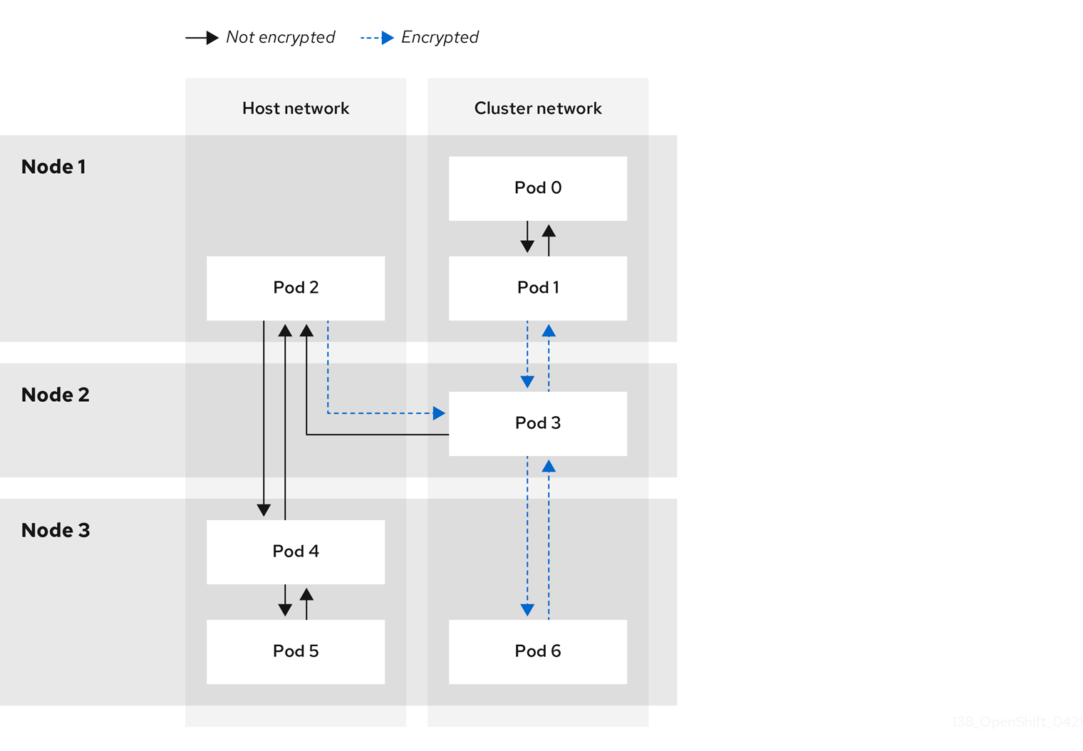
26.11.4.2. Encryption protocol and IPsec mode
The encrypt cipher used is AES-GCM-16-256. The integrity check value (ICV) is 16 bytes. The key length is 256 bits.
The IPsec mode used is Transport mode, a mode that encrypts end-to-end communication by adding an Encapsulated Security Payload (ESP) header to the IP header of the original packet and encrypts the packet data. OpenShift Container Platform does not currently use or support IPsec Tunnel mode for pod-to-pod communication.
26.11.4.3. Security certificate generation and rotation
The Cluster Network Operator (CNO) generates a self-signed X.509 certificate authority (CA) that is used by IPsec for encryption. Certificate signing requests (CSRs) from each node are automatically fulfilled by the CNO.
The CA is valid for 10 years. The individual node certificates are valid for 5 years and are automatically rotated after 4 1/2 years elapse.
26.11.5. IPsec encryption for external traffic
OpenShift Container Platform supports the use of IPsec to encrypt traffic destined for external hosts, ensuring confidentiality and integrity of data in transit. This feature relies on X.509 certificates that you must supply.
26.11.5.1. Supported platforms
This feature is supported on the following platforms:
- Bare metal
- Google Cloud
- Red Hat OpenStack Platform (RHOSP)
- VMware vSphere
If you have Red Hat Enterprise Linux (RHEL) compute nodes, these do not support IPsec encryption for external traffic.
If your cluster uses hosted control planes for Red Hat OpenShift Container Platform, configuring IPsec for encrypting traffic to external hosts is not supported.
26.11.5.2. Limitations
Ensure that the following prohibitions are observed:
- IPv6 configuration is not currently supported by the NMState Operator when configuring IPsec for external traffic.
-
Certificate common names (CN) in the provided certificate bundle must not begin with the
ovs_prefix, because this naming can conflict with pod-to-pod IPsec CN names in the Network Security Services (NSS) database of each node.
26.11.6. Enabling IPsec encryption
As a cluster administrator, you can enable pod-to-pod IPsec encryption, IPsec encryption between the cluster, and external IPsec endpoints.
You can configure IPsec in either of the following modes:
-
Full: Encryption for pod-to-pod and external traffic -
External: Encryption for external traffic
If you configure IPsec in Full mode, you must also complete the "Configuring IPsec encryption for external traffic" procedure.
Prerequisites
-
Install the OpenShift CLI (
oc). -
You are logged in to the cluster as a user with
cluster-adminprivileges. -
You have reduced the size of your cluster MTU by
46bytes to allow for the overhead of the IPsec ESP header.
Procedure
To enable IPsec encryption, enter the following command:
$ oc patch networks.operator.openshift.io cluster --type=merge -p \
  '{
  "spec":{
    "defaultNetwork":{
      "ovnKubernetesConfig":{
        "ipsecConfig":{
          "mode":"<mode">
1 }}}}}'- 1
- Specify
Externalto encrypt traffic to external hosts or specifyFullto encrypt pod-to-pod traffic and, optionally, traffic to external hosts. By default, IPsec is disabled.
- Encrypt external traffic with IPsec by completing the "Configuring IPsec encryption for external traffic" procedure.
Verification
To find the names of the OVN-Kubernetes data plane pods, enter the following command:
$ oc get pods -n openshift-ovn-kubernetes -l=app=ovnkube-nodeExample output
ovnkube-node-5xqbf                       8/8     Running   0              28m
ovnkube-node-6mwcx                       8/8     Running   0              29m
ovnkube-node-ck5fr                       8/8     Running   0              31m
ovnkube-node-fr4ld                       8/8     Running   0              26m
ovnkube-node-wgs4l                       8/8     Running   0              33m
ovnkube-node-zfvcl                       8/8     Running   0              34m
...
Verify that IPsec is enabled on your cluster by running the following command:
NoteAs a cluster administrator, you can verify that IPsec is enabled between pods on your cluster when IPsec is configured in
Fullmode. This step does not verify whether IPsec is working between your cluster and external hosts.$ oc -n openshift-ovn-kubernetes rsh ovnkube-node-<XXXXX> ovn-nbctl --no-leader-only get nb_global . ipsec1 - 1
- Where
<XXXXX>specifies the random sequence of letters for a pod from the previous step.
Example output
true
26.11.7. Configuring IPsec encryption for external traffic
As a cluster administrator, to encrypt external traffic with IPsec you must configure IPsec for your network infrastructure, including providing PKCS#12 certificates. Because this procedure uses Butane to create machine configs, you must have the butane command installed.
After you apply the machine config, the Machine Config Operator reboots affected nodes in your cluster to rollout the new machine config.
Prerequisites
-
Install the OpenShift CLI (
oc). -
You have installed the
butaneutility on your local computer. - You have installed the NMState Operator on the cluster.
-
You are logged in to the cluster as a user with
cluster-adminprivileges. - You have an existing PKCS#12 certificate for the IPsec endpoint and a CA cert in PEM format.
-
You enabled IPsec in either
FullorExternalmode on your cluster. -
You must set the
routingViaHostparameter totruein theovnKubernetesConfig.gatewayConfigspecification of the OVN-Kubernetes network plugin.
Procedure
Create an IPsec configuration with an NMState Operator node network configuration policy. For more information, see Libreswan as an IPsec VPN implementation.
To identify the IP address of the cluster node that is the IPsec endpoint, enter the following command:
$ oc get nodesCreate a file named
ipsec-config.yamlthat contains a node network configuration policy for the NMState Operator, such as in the following examples. For an overview aboutNodeNetworkConfigurationPolicyobjects, see The Kubernetes NMState project.Example NMState IPsec transport configuration
apiVersion: nmstate.io/v1
kind: NodeNetworkConfigurationPolicy
metadata:
  name: ipsec-config
spec:
  nodeSelector:
    kubernetes.io/hostname: "<hostname>"
1 desiredState: interfaces: - name: <interface_name>2 type: ipsec libreswan: left: <cluster_node>3 leftid: '%fromcert' leftrsasigkey: '%cert' leftcert: left_server leftmodecfgclient: false right: <external_host>4 rightid: '%fromcert' rightrsasigkey: '%cert' rightsubnet: <external_address>/325 ikev2: insist type: transport- 1
- Specifies the host name to apply the policy to. This host serves as the left side host in the IPsec configuration.
- 2
- Specifies the name of the interface to create on the host.
- 3
- Specifies the host name of the cluster node that terminates the IPsec tunnel on the cluster side. The name should match SAN
[Subject Alternate Name]from your supplied PKCS#12 certificates. - 4
- Specifies the external host name, such as
host.example.com. The name should match the SAN[Subject Alternate Name]from your supplied PKCS#12 certificates. - 5
- Specifies the IP address of the external host, such as
10.1.2.3/32.
Example NMState IPsec tunnel configuration
apiVersion: nmstate.io/v1
kind: NodeNetworkConfigurationPolicy
metadata:
  name: ipsec-config
spec:
  nodeSelector:
    kubernetes.io/hostname: "<hostname>"
1 desiredState: interfaces: - name: <interface_name>2 type: ipsec libreswan: left: <cluster_node>3 leftid: '%fromcert' leftmodecfgclient: false leftrsasigkey: '%cert' leftcert: left_server right: <external_host>4 rightid: '%fromcert' rightrsasigkey: '%cert' rightsubnet: <external_address>/325 ikev2: insist type: tunnel- 1
- Specifies the host name to apply the policy to. This host serves as the left side host in the IPsec configuration.
- 2
- Specifies the name of the interface to create on the host.
- 3
- Specifies the host name of the cluster node that terminates the IPsec tunnel on the cluster side. The name should match SAN
[Subject Alternate Name]from your supplied PKCS#12 certificates. - 4
- Specifies the external host name, such as
host.example.com. The name should match the SAN[Subject Alternate Name]from your supplied PKCS#12 certificates. - 5
- Specifies the IP address of the external host, such as
10.1.2.3/32.
To configure the IPsec interface, enter the following command:
$ oc create -f ipsec-config.yaml
Provide the following certificate files to add to the Network Security Services (NSS) database on each host. These files are imported as part of the Butane configuration in subsequent steps.
-
left_server.p12: The certificate bundle for the IPsec endpoints -
ca.pem: The certificate authority that you signed your certificates with
-
Create a machine config to add your certificates to the cluster:
To create Butane config files for the control plane and worker nodes, enter the following command:
NoteThe Butane version you specify in the config file should match the OpenShift Container Platform version and always ends in
0. For example,4.15.0. See "Creating machine configs with Butane" for information about Butane.$ for role in master worker; do cat >> "99-ipsec-${role}-endpoint-config.bu" <<-EOF variant: openshift version: 4.15.0 metadata: name: 99-${role}-import-certs labels: machineconfiguration.openshift.io/role: $role systemd: units: - name: ipsec-import.service enabled: true contents: | [Unit] Description=Import external certs into ipsec NSS Before=ipsec.service [Service] Type=oneshot ExecStart=/usr/local/bin/ipsec-addcert.sh RemainAfterExit=false StandardOutput=journal [Install] WantedBy=multi-user.target storage: files: - path: /etc/pki/certs/ca.pem mode: 0400 overwrite: true contents: local: ca.pem - path: /etc/pki/certs/left_server.p12 mode: 0400 overwrite: true contents: local: left_server.p12 - path: /usr/local/bin/ipsec-addcert.sh mode: 0740 overwrite: true contents: inline: | #!/bin/bash -e echo "importing cert to NSS" certutil -A -n "CA" -t "CT,C,C" -d /var/lib/ipsec/nss/ -i /etc/pki/certs/ca.pem pk12util -W "" -i /etc/pki/certs/left_server.p12 -d /var/lib/ipsec/nss/ certutil -M -n "left_server" -t "u,u,u" -d /var/lib/ipsec/nss/ EOF doneTo transform the Butane files that you created in the previous step into machine configs, enter the following command:
$ for role in master worker; do
  butane -d . 99-ipsec-${role}-endpoint-config.bu -o ./99-ipsec-$role-endpoint-config.yaml
done
To apply the machine configs to your cluster, enter the following command:
$ for role in master worker; do oc apply -f 99-ipsec-${role}-endpoint-config.yaml doneImportantAs the Machine Config Operator (MCO) updates machines in each machine config pool, it reboots each node one by one. You must wait until all the nodes are updated before external IPsec connectivity is available.
Check the machine config pool status by entering the following command:
$ oc get mcpA successfully updated node has the following status:
UPDATED=true,UPDATING=false,DEGRADED=false.NoteBy default, the MCO updates one machine per pool at a time, causing the total time the migration takes to increase with the size of the cluster.
To confirm that IPsec machine configs rolled out successfully, enter the following commands:
Confirm that the IPsec machine configs were created:
$ oc get mc | grep ipsecExample output
80-ipsec-master-extensions        3.2.0        6d15h
80-ipsec-worker-extensions        3.2.0        6d15h
Confirm that the that the IPsec extension are applied to control plane nodes:
$ oc get mcp master -o yaml | grep 80-ipsec-master-extensions -cExpected output
2Confirm that the that the IPsec extension are applied to worker nodes:
$ oc get mcp worker -o yaml | grep 80-ipsec-worker-extensions -cExpected output
2
26.11.8. Disabling IPsec encryption for an external IPsec endpoint
As a cluster administrator, you can remove an existing IPsec tunnel to an external host.
Prerequisites
-
Install the OpenShift CLI (
oc). -
You are logged in to the cluster as a user with
cluster-adminprivileges. -
You enabled IPsec in either
FullorExternalmode on your cluster.
Procedure
Create a file named
remove-ipsec-tunnel.yamlwith the following YAML:kind: NodeNetworkConfigurationPolicy apiVersion: nmstate.io/v1 metadata: name: <name> spec: nodeSelector: kubernetes.io/hostname: <node_name> desiredState: interfaces: - name: <tunnel_name> type: ipsec state: absentwhere:
name- Specifies a name for the node network configuration policy.
node_name- Specifies the name of the node where the IPsec tunnel that you want to remove exists.
tunnel_name- Specifies the interface name for the existing IPsec tunnel.
To remove the IPsec tunnel, enter the following command:
$ oc apply -f remove-ipsec-tunnel.yaml
26.11.9. Disabling IPsec encryption
As a cluster administrator, you can disable IPsec encryption.
Prerequisites
-
Install the OpenShift CLI (
oc). -
Log in to the cluster with a user with
cluster-adminprivileges.
Procedure
To disable IPsec encryption, enter the following command:
$ oc patch networks.operator.openshift.io cluster --type=merge \ -p '{ "spec":{ "defaultNetwork":{ "ovnKubernetesConfig":{ "ipsecConfig":{ "mode":"Disabled" }}}}}'-
Optional: You can increase the size of your cluster MTU by
46bytes because there is no longer any overhead from the IPsec ESP header in IP packets.
26.11.10. Additional resources
- Configuring a VPN with IPsec in Red Hat Enterprise Linux (RHEL) 9
- Installing Butane
- About the OVN-Kubernetes Container Network Interface (CNI) network plugin
- Changing the MTU for the cluster network
- link:https://docs.redhat.com/en/documentation/openshift_container_platform/4.15/html-single/operator_apis/#network-operator-openshift-io-v1[Network [operator.openshift.io/v1\] API
26.12. Configure an external gateway on the default network
As a cluster administrator, you can configure an external gateway on the default network.
This feature offers the following benefits:
- Granular control over egress traffic on a per-namespace basis
- Flexible configuration of static and dynamic external gateway IP addresses
- Support for both IPv4 and IPv6 address families
26.12.1. Prerequisites
- Your cluster uses the OVN-Kubernetes network plugin.
- Your infrastructure is configured to route traffic from the secondary external gateway.
26.12.2. How OpenShift Container Platform determines the external gateway IP address
You configure a secondary external gateway with the AdminPolicyBasedExternalRoute custom resource (CR) from the k8s.ovn.org API group. The CR supports static and dynamic approaches to specifying an external gateway’s IP address.
Each namespace that a AdminPolicyBasedExternalRoute CR targets cannot be selected by any other AdminPolicyBasedExternalRoute CR. A namespace cannot have concurrent secondary external gateways.
Changes to policies are isolated in the controller. If a policy fails to apply, changes to other policies do not trigger a retry of other policies. Policies are only re-evaluated, applying any differences that might have occurred by the change, when updates to the policy itself or related objects to the policy such as target namespaces, pod gateways, or namespaces hosting them from dynamic hops are made.
- Static assignment
- You specify an IP address directly.
- Dynamic assignment
You specify an IP address indirectly, with namespace and pod selectors, and an optional network attachment definition.
- If the name of a network attachment definition is provided, the external gateway IP address of the network attachment is used.
-
If the name of a network attachment definition is not provided, the external gateway IP address for the pod itself is used. However, this approach works only if the pod is configured with
hostNetworkset totrue.
26.12.3. AdminPolicyBasedExternalRoute object configuration
You can define an AdminPolicyBasedExternalRoute object, which is cluster scoped, with the following properties. A namespace can be selected by only one AdminPolicyBasedExternalRoute CR at a time.
| Field | Type | Description |
|---|---|---|
|
|
|
Specifies the name of the |
|
|
|
Specifies a namespace selector that the routing polices apply to. Only
A namespace can only be targeted by one |
|
|
|
Specifies the destinations where the packets are forwarded to. Must be either or both of |
| Field | Type | Description |
|---|---|---|
|
|
| Specifies an array of static IP addresses. |
|
|
| Specifies an array of pod selectors corresponding to pods configured with a network attachment definition to use as the external gateway target. |
| Field | Type | Description |
|---|---|---|
|
|
| Specifies either an IPv4 or IPv6 address of the next destination hop. |
|
|
|
Optional: Specifies whether Bi-Directional Forwarding Detection (BFD) is supported by the network. The default value is |
| Field | Type | Description |
|---|---|---|
|
|
| Specifies a [set-based](https://kubernetes.io/docs/concepts/overview/working-with-objects/labels/#set-based-requirement) label selector to filter the pods in the namespace that match this network configuration. |
|
|
|
Specifies a |
|
|
|
Optional: Specifies whether Bi-Directional Forwarding Detection (BFD) is supported by the network. The default value is |
|
|
| Optional: Specifies the name of a network attachment definition. The name must match the list of logical networks associated with the pod. If this field is not specified, the host network of the pod is used. However, the pod must be configure as a host network pod to use the host network. |
26.12.3.1. Example secondary external gateway configurations
In the following example, the AdminPolicyBasedExternalRoute object configures two static IP addresses as external gateways for pods in namespaces with the kubernetes.io/metadata.name: novxlan-externalgw-ecmp-4059 label.
apiVersion: k8s.ovn.org/v1
kind: AdminPolicyBasedExternalRoute
metadata:
name: default-route-policy
spec:
from:
  namespaceSelector:
    matchLabels:
      kubernetes.io/metadata.name: novxlan-externalgw-ecmp-4059
nextHops:
static:
- ip: "172.18.0.8"
- ip: "172.18.0.9"
In the following example, the AdminPolicyBasedExternalRoute object configures a dynamic external gateway. The IP addresses used for the external gateway are derived from the additional network attachments associated with each of the selected pods.
apiVersion: k8s.ovn.org/v1
kind: AdminPolicyBasedExternalRoute
metadata:
  name: shadow-traffic-policy
spec:
  from:
    namespaceSelector:
      matchLabels:
        externalTraffic: ""
  nextHops:
    dynamic:
    - podSelector:
        matchLabels:
          gatewayPod: ""
      namespaceSelector:
        matchLabels:
          shadowTraffic: ""
      networkAttachmentName: shadow-gateway
    - podSelector:
        matchLabels:
          gigabyteGW: ""
      namespaceSelector:
        matchLabels:
          gatewayNamespace: ""
      networkAttachmentName: gateway
In the following example, the AdminPolicyBasedExternalRoute object configures both static and dynamic external gateways.
apiVersion: k8s.ovn.org/v1
kind: AdminPolicyBasedExternalRoute
metadata:
  name: multi-hop-policy
spec:
  from:
    namespaceSelector:
      matchLabels:
        trafficType: "egress"
  nextHops:
    static:
    - ip: "172.18.0.8"
    - ip: "172.18.0.9"
    dynamic:
    - podSelector:
        matchLabels:
          gatewayPod: ""
      namespaceSelector:
        matchLabels:
          egressTraffic: ""
      networkAttachmentName: gigabyte
26.12.4. Configure a secondary external gateway
You can configure an external gateway on the default network for a namespace in your cluster.
Prerequisites
-
You installed the OpenShift CLI (
oc). -
You are logged in to the cluster with a user with
cluster-adminprivileges.
Procedure
-
Create a YAML file that contains an
AdminPolicyBasedExternalRouteobject. To create an admin policy based external route, enter the following command:
$ oc create -f <file>.yamlwhere:
<file>- Specifies the name of the YAML file that you created in the previous step.
Example output
adminpolicybasedexternalroute.k8s.ovn.org/default-route-policy createdTo confirm that the admin policy based external route was created, enter the following command:
$ oc describe apbexternalroute <name> | tail -n 6where:
<name>-
Specifies the name of the
AdminPolicyBasedExternalRouteobject.
Example output
Status:
  Last Transition Time:  2023-04-24T15:09:01Z
  Messages:
  Configured external gateway IPs: 172.18.0.8
  Status:  Success
Events:  <none>
26.12.5. Additional resources
- For more information about additional network attachments, see Understanding multiple networks
26.13. Configuring an egress firewall for a project
As a cluster administrator, you can create an egress firewall for a project that restricts egress traffic leaving your OpenShift Container Platform cluster.
26.13.1. How an egress firewall works in a project
As a cluster administrator, you can use an egress firewall to limit the external hosts that some or all pods can access from within the cluster. An egress firewall supports the following scenarios:
- A pod can only connect to internal hosts and cannot initiate connections to the public internet.
- A pod can only connect to the public internet and cannot initiate connections to internal hosts that are outside the OpenShift Container Platform cluster.
- A pod cannot reach specified internal subnets or hosts outside the OpenShift Container Platform cluster.
- A pod can only connect to specific external hosts.
For example, you can allow one project access to a specified IP range but deny the same access to a different project. Or, you can restrict application developers from updating from Python pip mirrors, and force updates to come only from approved sources.
You configure an egress firewall policy by creating an EgressFirewall custom resource (CR). The egress firewall matches network traffic that meets any of the following criteria:
- An IP address range in CIDR format
- A DNS name that resolves to an IP address
- A port number
- A protocol that is one of the following protocols: TCP, UDP, and SCTP
26.13.1.1. Limitations of an egress firewall
An egress firewall has the following limitations:
-
No project can have more than one
EgressFirewallCR. -
Egress firewall rules do not apply to traffic that goes through routers. Any user with permission to create a
RouteCR object can bypass egress firewall policy rules by creating a route that points to a forbidden destination. - Egress firewall does not apply to the host network namespace. Pods with host networking enabled are unaffected by egress firewall rules.
If your egress firewall includes a deny rule for
0.0.0.0/0, access to your OpenShift Container Platform API servers is blocked. You must either add allow rules for each IP address or use thenodeSelectortype allow rule in your egress policy rules to connect to API servers.The following example illustrates the order of the egress firewall rules necessary to ensure API server access:
EgressFirewallAPI server access exampleapiVersion: k8s.ovn.org/v1 kind: EgressFirewall metadata: name: default namespace: <namespace>1 spec: egress: - to: cidrSelector: <api_server_address_range>2 type: Allow # ... - to: cidrSelector: 0.0.0.0/03 type: Denywhere:
- <namespace>
- Specifies the namespace for the egress firewall.
- <api_server_address_range>
- Specifies the IP address range that includes your OpenShift Container Platform API servers.
- <cidrSelector>
Specifies a value of
0.0.0.0/0to set a global deny rule that prevents access to the OpenShift Container Platform API servers.To find the IP address for your API servers, run
oc get ep kubernetes -n default.For more information, see BZ#1988324.
-
A maximum of one
EgressFirewallobject with a maximum of 8,000 rules can be defined per project. - If you are using the OVN-Kubernetes network plugin with shared gateway mode in Red Hat OpenShift Networking, return ingress replies are affected by egress firewall rules. If the egress firewall rules drop the ingress reply destination IP, the traffic is dropped.
- In general, using Domain Name Server (DNS) names in your egress firewall policy does not affect local DNS resolution through CoreDNS. However, if your egress firewall policy uses domain names and an external DNS server handles DNS resolution for an affected pod, you must include egress firewall rules that permit access to the IP addresses of your DNS server.
Violating any of these restrictions results in a broken egress firewall for the project. Consequently, all external network traffic is dropped, which can cause security risks for your organization.
An EgressFirewall resource is created in the kube-node-lease, kube-public, kube-system, openshift and openshift- projects.
26.13.1.2. Matching order for egress firewall policy rules
OVN-Kubernetes evaluates egress firewall policy rules in the order they are defined in, from first to last. The first rule that matches an egress connection from a pod applies. Any subsequent rules are ignored for that connection.
26.13.1.3. How Domain Name Server (DNS) resolution works
If you use DNS names in any of your egress firewall policy rules, proper resolution of the domain names is subject to the following restrictions:
- Domain name updates are polled based on a time-to-live (TTL) duration. By default, the duration is 30 minutes. When the egress firewall controller queries the local name servers for a domain name, if the response includes a TTL and the TTL is less than 30 minutes, the controller sets the duration for that DNS name to the returned value. Each DNS name is queried after the TTL for the DNS record expires.
- The pod must resolve the domain from the same local name servers when necessary. Otherwise the IP addresses for the domain known by the egress firewall controller and the pod can be different. If the IP addresses for a hostname differ, the egress firewall might not be enforced consistently.
-
Because the egress firewall controller and pods asynchronously poll the same local name server, the pod might obtain the updated IP address before the egress controller does, which causes a race condition. Due to this current limitation, domain name usage in
EgressFirewallobjects is only recommended for domains with infrequent IP address changes.
26.13.1.3.1. Improved DNS resolution and resolving wildcard domain names
There might be situations where the IP addresses associated with a DNS record change frequently, or you might want to specify wildcard domain names in your egress firewall policy rules.
In this situation, the OVN-Kubernetes cluster manager creates a DNSNameResolver custom resource object for each unique DNS name used in your egress firewall policy rules. This custom resource stores the following information:
Improved DNS resolution for egress firewall rules is a Technology Preview feature only. Technology Preview features are not supported with Red Hat production service level agreements (SLAs) and might not be functionally complete. Red Hat does not recommend using them in production. These features provide early access to upcoming product features, enabling customers to test functionality and provide feedback during the development process.
For more information about the support scope of Red Hat Technology Preview features, see Technology Preview Features Support Scope.
Example DNSNameResolver CR definition
apiVersion: networking.openshift.io/v1alpha1
kind: DNSNameResolver
spec:
  name: www.example.com.
status:
  resolvedNames:
  - dnsName: www.example.com.
    resolvedAddress:
    - ip: "1.2.3.4"
      ttlSeconds: 60
      lastLookupTime: "2023-08-08T15:07:04Z"
where:
- <name>
- Specifies the DNS name. This can be either a standard DNS name or a wildcard DNS name. For a wildcard DNS name, the DNS name resolution information contains all of the DNS names that match the wildcard DNS name.
- <dnsName>
-
Specifies the resolved DNS name matching the
spec.namefield. If thespec.namefield contains a wildcard DNS name, then multiplednsNameentries are created that contain the standard DNS names that match the wildcard DNS name when resolved. If the wildcard DNS name can also be successfully resolved, then this field also stores the wildcard DNS name. <ip> Specifies the current IP addresses associated with the DNS name. - <ttlSeconds>
- Specifies the last time-to-live (TTL) duration.
- <lastLookupTime>
- Specifies the last lookup time.
If during DNS resolution the DNS name in the query matches any name defined in a DNSNameResolver CR, then the previous information is updated accordingly in the CR status field. For unsuccessful DNS wildcard name lookups, the request is retried after a default TTL of 30 minutes.
The OVN-Kubernetes cluster manager watches for updates to an EgressFirewall custom resource object, and creates, modifies, or deletes DNSNameResolver CRs associated with those egress firewall policies when that update occurs.
Do not modify DNSNameResolver custom resources directly. This can lead to unwanted behavior of your egress firewall.
26.13.2. EgressFirewall custom resource (CR)
You can define one or more rules for an egress firewall. A rule is either an Allow rule or a Deny rule, with a specification for the traffic that the rule applies to.
The following YAML describes an EgressFirewall CR:
EgressFirewall object
apiVersion: k8s.ovn.org/v1
kind: EgressFirewall
metadata:
  name: <ovn>
spec:
  egress: <egress_rules>
    ...
where:
- <ovn>
-
The name for the object must be
default. - <egress_rules>
- Specifies a collection of one or more egress network policy rules as described in the following section.
26.13.2.1. EgressFirewall rules
The following YAML describes the rules for an EgressFirewall resource. The user can select either an IP address range in CIDR format, a domain name, or use the nodeSelector field to allow or deny egress traffic. The egress stanza expects an array of one or more objects.
Egress policy rule stanza
egress:
- type: <type>
  to:
    cidrSelector: <cidr_range>
    dnsName: <dns_name>
    nodeSelector: <label_name>: <label_value>
  ports: <optional_port>
      ...
where:
- <type>
-
Specifies the type of rule. The value must be either
AlloworDeny. - <to>
-
Specifies a stanza describing an egress traffic match rule that specifies the
cidrSelectorfield or thednsNamefield. You cannot use both fields in the same rule. - <cidr_range>
- Specifies an IP address range in CIDR format.
- <dns_name>
- Specifies a DNS domain name.
- <nodeSelector>
-
Specifies labels which are key and value pairs that the user defines. Labels are attached to objects, such as pods. The
nodeSelectorallows for one or more node labels to be selected and attached to pods. - <ports>
- Specifies an optional field that describes a collection of network ports and protocols for the rule.
Ports stanza
ports:
- port:
  protocol:
where:
- <port>
-
Specifies a network port, such as
80or443. If you specify a value for this field, you must also specify a value for theprotocolfield. - <protocol>
-
Specifies a network protocol. The value must be either
TCP,UDP, orSCTP.
26.13.2.2. Example EgressFirewall CR
The following example defines several egress firewall policy rules:
apiVersion: k8s.ovn.org/v1
kind: EgressFirewall
metadata:
  name: default
spec:
  egress:
  - type: Allow
    to:
      cidrSelector: 1.2.3.0/24
  - type: Deny
    to:
      cidrSelector: 0.0.0.0/0
where:
- <egress>
- Specifies a collection of egress firewall policy rule objects.
The following example defines a policy rule that denies traffic to the host at the 172.16.1.1/32 IP address, if the traffic is using either the TCP protocol and destination port 80 or any protocol and destination port 443.
apiVersion: k8s.ovn.org/v1
kind: EgressFirewall
metadata:
  name: default
spec:
  egress:
  - type: Deny
    to:
      cidrSelector: 172.16.1.1/32
    ports:
    - port: 80
      protocol: TCP
    - port: 443
26.13.2.3. Example EgressFirewall CR using nodeSelector
As a cluster administrator, you can allow or deny egress traffic to nodes in your cluster by specifying a label using nodeSelector field. Labels can be applied to one or more nodes. Labels can be helpful because instead of adding manual rules per node IP address, you can use node selectors to create a label that allows pods behind an egress firewall to access host network pods. The following is an example with the region=east label:
apiVersion: k8s.ovn.org/v1
kind: EgressFirewall
metadata:
  name: default
spec:
    egress:
    - to:
        nodeSelector:
          matchLabels:
            region: east
      type: Allow
26.13.3. Creating an EgressFirewall custom resource (CR)
As a cluster administrator, you can create an egress firewall policy object for a project.
If the project already has an EgressFirewall resource, you must edit the existing policy to make changes to egress firewall rules.
Prerequisites
- A cluster that uses the OVN-Kubernetes network plugin.
-
Install the OpenShift CLI (
oc). - You must log in to the cluster as a cluster administrator.
Procedure
Create a policy rule:
-
Create a
<policy_name>.yamlfile where<policy_name>describes the egress policy rules. -
Define the
EgressFirewallobject in the file.
-
Create a
Create the policy object by entering the following command. Replace
<policy_name>with the name of the policy and<project>with the project that the rule applies to.$ oc create -f <policy_name>.yaml -n <project>Successful output lists the
egressfirewall.k8s.ovn.org/v1name and thecreatedstatus.-
Optional: Save the
<policy_name>.yamlfile so that you can make changes later.
26.14. Viewing an egress firewall for a project
As a cluster administrator, you can list the names of any existing egress firewalls and view the traffic rules for a specific egress firewall.
26.14.1. Viewing an EgressFirewall custom resource (CR)
You can view an EgressFirewall CR in your cluster.
Prerequisites
- A cluster using the OVN-Kubernetes network plugin.
-
Install the OpenShift Command-line Interface (CLI), commonly known as
oc. - You must log in to the cluster.
Procedure
Optional: To view the names of the
EgressFirewallCR defined in your cluster, enter the following command:$ oc get egressfirewall --all-namespacesTo inspect a policy, enter the following command. Replace
<policy_name>with the name of the policy to inspect.$ oc describe egressfirewall <policy_name>Example output
Name:		default
Namespace:	project1
Created:	20 minutes ago
Labels:		<none>
Annotations:	<none>
Rule:		Allow to 1.2.3.0/24
Rule:		Allow to www.example.com
Rule:		Deny to 0.0.0.0/0
26.15. Editing an egress firewall for a project
As a cluster administrator, you can modify network traffic rules for an existing egress firewall.
26.15.1. Editing an EgressFirewall custom resource (CR)
As a cluster administrator, you can update the egress firewall for a project.
Prerequisites
- A cluster using the OVN-Kubernetes network plugin.
-
Install the OpenShift CLI (
oc). - You must log in to the cluster as a cluster administrator.
Procedure
Find the name of the
EgressFirewallCR for the project. Replace<project>with the name of the project.$ oc get -n <project> egressfirewallOptional: If you did not save a copy of the
EgressFirewallobject when you created the egress network firewall, enter the following command to create a copy.$ oc get -n <project> egressfirewall <name> -o yaml > <filename>.yamlReplace
<project>with the name of the project. Replace<name>with the name of the object. Replace<filename>with the name of the file to save the YAML to.After making changes to the policy rules, enter the following command to replace the
EgressFirewallCR. Replace<filename>with the name of the file containing the updatedEgressFirewallCR.$ oc replace -f <filename>.yaml
26.16. Removing an egress firewall from a project
As a cluster administrator, you can remove an egress firewall from a project to remove all restrictions on network traffic from the project that leaves the OpenShift Container Platform cluster.
26.16.1. Removing an EgressFirewall CR
As a cluster administrator, you can remove an egress firewall from a project.
Prerequisites
- A cluster using the OVN-Kubernetes network plugin.
-
Install the OpenShift CLI (
oc). - You must log in to the cluster as a cluster administrator.
Procedure
Find the name of the
EgressFirewallCR for the project. Replace<project>with the name of the project.$ oc get egressfirewall -n <project>Delete the
EgressFirewallCR by entering the following command. Replace<project>with the name of the project and<name>with the name of the object.$ oc delete -n <project> egressfirewall <name>
26.17. Configuring an egress IP address
As a cluster administrator, you can configure the OVN-Kubernetes Container Network Interface (CNI) network plugin to assign one or more egress IP addresses to a namespace, or to specific pods in a namespace.
Configuring egress IPs is not supported for ROSA with HCP clusters at this time.
26.17.1. Egress IP address architectural design and implementation
By using the OpenShift Container Platform egress IP address functionality, you can ensure that the traffic from one or more pods in one or more namespaces has a consistent source IP address for services outside the cluster network.
For example, you might have a pod that periodically queries a database that is hosted on a server outside of your cluster. To enforce access requirements for the server, a packet filtering device is configured to allow traffic only from specific IP addresses. To ensure that you can reliably allow access to the server from only that specific pod, you can configure a specific egress IP address for the pod that makes the requests to the server.
An egress IP address assigned to a namespace is different from an egress router, which is used to send traffic to specific destinations.
In some cluster configurations, application pods and ingress router pods run on the same node. If you configure an egress IP address for an application project in this scenario, the IP address is not used when you send a request to a route from the application project.
Egress IP addresses must not be configured in any Linux network configuration files, such as ifcfg-eth0.
26.17.1.1. Platform support
The Egress IP address feature that runs on a primary host network is supported on the following platforms:
| Platform | Supported |
|---|---|
| Bare metal | Yes |
| VMware vSphere | Yes |
| Red Hat OpenStack Platform (RHOSP) | Yes |
| Amazon Web Services (AWS) | Yes |
| Google Cloud | Yes |
| Microsoft Azure | Yes |
| IBM Z® and IBM® LinuxONE | Yes |
| IBM Z® and IBM® LinuxONE for Red Hat Enterprise Linux (RHEL) KVM | Yes |
| IBM Power® | Yes |
| Nutanix | Yes |
The Egress IP address feature that runs on secondary host networks is supported on the following platform:
| Platform | Supported |
|---|---|
| Bare metal | Yes |
The assignment of egress IP addresses to control plane nodes with the EgressIP feature is not supported on a cluster provisioned on Amazon Web Services (AWS). (BZ#2039656).
26.17.1.2. Public cloud platform considerations
Typically, public cloud providers place a limit on egress IPs. This means that there is a constraint on the absolute number of assignable IP addresses per node for clusters provisioned on public cloud infrastructure. The maximum number of assignable IP addresses per node, or the IP capacity, can be described in the following formula:
IP capacity = public cloud default capacity - sum(current IP assignments)While the Egress IPs capability manages the IP address capacity per node, it is important to plan for this constraint in your deployments. For example, if a public cloud provider limits IP address capacity to 10 IP addresses per node, and you have 8 nodes, the total number of assignable IP addresses is only 80. To achieve a higher IP address capacity, you would need to allocate additional nodes. For example, if you needed 150 assignable IP addresses, you would need to allocate 7 additional nodes.
To confirm the IP capacity and subnets for any node in your public cloud environment, you can enter the oc get node <node_name> -o yaml command. The cloud.network.openshift.io/egress-ipconfig annotation includes capacity and subnet information for the node.
The annotation value is an array with a single object with fields that provide the following information for the primary network interface:
-
interface: Specifies the interface ID on AWS and Azure and the interface name on Google Cloud. -
ifaddr: Specifies the subnet mask for one or both IP address families. -
capacity: Specifies the IP address capacity for the node. On AWS, the IP address capacity is provided per IP address family. On Azure and Google Cloud, the IP address capacity includes both IPv4 and IPv6 addresses.
Automatic attachment and detachment of egress IP addresses for traffic between nodes are available. This allows for traffic from many pods in namespaces to have a consistent source IP address to locations outside of the cluster. This also supports OpenShift SDN and OVN-Kubernetes, which is the default networking plugin in Red Hat OpenShift Networking in OpenShift Container Platform 4.15.
The RHOSP egress IP address feature creates a Neutron reservation port called egressip-<IP address>. Using the same RHOSP user as the one used for the OpenShift Container Platform cluster installation, you can assign a floating IP address to this reservation port to have a predictable SNAT address for egress traffic. When an egress IP address on an RHOSP network is moved from one node to another, because of a node failover, for example, the Neutron reservation port is removed and recreated. This means that the floating IP association is lost and you need to manually reassign the floating IP address to the new reservation port.
When an RHOSP cluster administrator assigns a floating IP to the reservation port, OpenShift Container Platform cannot delete the reservation port. The CloudPrivateIPConfig object cannot perform delete and move operations until an RHOSP cluster administrator unassigns the floating IP from the reservation port.
The following examples illustrate the annotation from nodes on several public cloud providers. The annotations are indented for readability.
Example cloud.network.openshift.io/egress-ipconfig annotation on AWS
cloud.network.openshift.io/egress-ipconfig: [
  {
    "interface":"eni-078d267045138e436",
    "ifaddr":{"ipv4":"10.0.128.0/18"},
    "capacity":{"ipv4":14,"ipv6":15}
  }
]
Example cloud.network.openshift.io/egress-ipconfig annotation on Google Cloud
cloud.network.openshift.io/egress-ipconfig: [
  {
    "interface":"nic0",
    "ifaddr":{"ipv4":"10.0.128.0/18"},
    "capacity":{"ip":14}
  }
]
The following sections describe the IP address capacity for supported public cloud environments for use in your capacity calculation.
26.17.1.2.1. Amazon Web Services (AWS) IP address capacity limits
On AWS, constraints on IP address assignments depend on the instance type configured. For more information, see IP addresses per network interface per instance type
26.17.1.2.2. Google Cloud IP address capacity limits
On Google Cloud, the networking model implements additional node IP addresses through IP address aliasing, rather than IP address assignments. However, IP address capacity maps directly to IP aliasing capacity.
The following capacity limits exist for IP aliasing assignment:
- Per node, the maximum number of IP aliases, both IPv4 and IPv6, is 100.
- Per VPC, the maximum number of IP aliases is unspecified, but OpenShift Container Platform scalability testing reveals the maximum to be approximately 15,000.
For more information, see Per instance quotas and Alias IP ranges overview.
26.17.1.2.3. Microsoft Azure IP address capacity limits
On Azure, the following capacity limits exist for IP address assignment:
- Per NIC, the maximum number of assignable IP addresses, for both IPv4 and IPv6, is 256.
- Per virtual network, the maximum number of assigned IP addresses cannot exceed 65,536.
For more information, see Networking limits.
26.17.1.3. Considerations for using an egress IP on additional network interfaces
In OpenShift Container Platform, egress IPs provide administrators a way to control network traffic. Egress IPs can be used with a br-ex Open vSwitch (OVS) bridge interface and any physical interface that has IP connectivity enabled.
You can inspect your network interface type by running the following command:
$ ip -details link show
The primary network interface is assigned a node IP address which also contains a subnet mask. Information for this node IP address can be retrieved from the Kubernetes node object for each node within your cluster by inspecting the k8s.ovn.org/node-primary-ifaddr annotation. In an IPv4 cluster, this annotation is similar to the following example: "k8s.ovn.org/node-primary-ifaddr: {"ipv4":"192.168.111.23/24"}".
If the egress IP is not within the subnet of the primary network interface subnet, you can use an egress IP on another Linux network interface that is not of the primary network interface type. By doing so, OpenShift Container Platform administrators are provided with a greater level of control over networking aspects such as routing, addressing, segmentation, and security policies. This feature provides users with the option to route workload traffic over specific network interfaces for purposes such as traffic segmentation or meeting specialized requirements.
If the egress IP is not within the subnet of the primary network interface, then the selection of another network interface for egress traffic might occur if they are present on a node.
You can determine which other network interfaces might support egress IPs by inspecting the k8s.ovn.org/host-cidrs Kubernetes node annotation. This annotation contains the addresses and subnet mask found for the primary network interface. It also contains additional network interface addresses and subnet mask information. These addresses and subnet masks are assigned to network interfaces that use the longest prefix match routing mechanism to determine which network interface supports the egress IP.
OVN-Kubernetes provides a mechanism to control and direct outbound network traffic from specific namespaces and pods. This ensures that it exits the cluster through a particular network interface and with a specific egress IP address.
26.17.1.3.1. Requirements for assigning an egress IP to a network interface that is not the primary network interface
For users who want an egress IP and traffic to be routed over a particular interface that is not the primary network interface, the following conditions must be met:
- OpenShift Container Platform is installed on a bare-metal cluster. This feature is disabled within a cloud or a hypervisor environment.
- Your OpenShift Container Platform pods are not configured as host-networked.
- If a network interface is removed or if the IP address and subnet mask which allows the egress IP to be hosted on the interface is removed, the egress IP is reconfigured. Consequently, the egress IP could be assigned to another node and interface.
- If you use an Egress IP address on a secondary network interface card (NIC), you must use the Node Tuning Operator to enable IP forwarding on the secondary NIC.
26.17.1.4. Assignment of egress IPs to pods
To assign one or more egress IPs to a namespace or specific pods in a namespace, the following conditions must be satisfied:
-
At least one node in your cluster must have the
k8s.ovn.org/egress-assignable: ""label. -
An
EgressIPobject exists that defines one or more egress IP addresses to use as the source IP address for traffic leaving the cluster from pods in a namespace.
If you create EgressIP objects prior to labeling any nodes in your cluster for egress IP assignment, OpenShift Container Platform might assign every egress IP address to the first node with the k8s.ovn.org/egress-assignable: "" label.
To ensure that egress IP addresses are widely distributed across nodes in the cluster, always apply the label to the nodes you intent to host the egress IP addresses before creating any EgressIP objects.
26.17.1.5. Assignment of egress IPs to nodes
When creating an EgressIP object, the following conditions apply to nodes that are labeled with the k8s.ovn.org/egress-assignable: "" label:
- An egress IP address is never assigned to more than one node at a time.
- An egress IP address is equally balanced between available nodes that can host the egress IP address.
If the
spec.EgressIPsarray in anEgressIPobject specifies more than one IP address, the following conditions apply:- No node will ever host more than one of the specified IP addresses.
- Traffic is balanced roughly equally between the specified IP addresses for a given namespace.
- If a node becomes unavailable, any egress IP addresses assigned to it are automatically reassigned, subject to the previously described conditions.
When a pod matches the selector for multiple EgressIP objects, there is no guarantee which of the egress IP addresses that are specified in the EgressIP objects is assigned as the egress IP address for the pod.
Additionally, if an EgressIP object specifies multiple egress IP addresses, there is no guarantee which of the egress IP addresses might be used. For example, if a pod matches a selector for an EgressIP object with two egress IP addresses, 10.10.20.1 and 10.10.20.2, either might be used for each TCP connection or UDP conversation.
26.17.1.6. Architectural diagram of an egress IP address configuration
The following diagram depicts an egress IP address configuration. The diagram describes four pods in two different namespaces running on three nodes in a cluster. The nodes are assigned IP addresses from the 192.168.126.0/18 CIDR block on the host network.
Both Node 1 and Node 3 are labeled with k8s.ovn.org/egress-assignable: "" and thus available for the assignment of egress IP addresses.
The dashed lines in the diagram depict the traffic flow from pod1, pod2, and pod3 traveling through the pod network to egress the cluster from Node 1 and Node 3. When an external service receives traffic from any of the pods selected by the example EgressIP object, the source IP address is either 192.168.126.10 or 192.168.126.102. The traffic is balanced roughly equally between these two nodes.
The following resources from the diagram are illustrated in detail:
NamespaceobjectsThe namespaces are defined in the following manifest:
Namespace objects
apiVersion: v1 kind: Namespace metadata: name: namespace1 labels: env: prod --- apiVersion: v1 kind: Namespace metadata: name: namespace2 labels: env: prodEgressIPobjectThe following
EgressIPobject describes a configuration that selects all pods in any namespace with theenvlabel set toprod. The egress IP addresses for the selected pods are192.168.126.10and192.168.126.102.EgressIPobjectapiVersion: k8s.ovn.org/v1 kind: EgressIP metadata: name: egressips-prod spec: egressIPs: - 192.168.126.10 - 192.168.126.102 namespaceSelector: matchLabels: env: prod status: items: - node: node1 egressIP: 192.168.126.10 - node: node3 egressIP: 192.168.126.102For the configuration in the previous example, OpenShift Container Platform assigns both egress IP addresses to the available nodes. The
statusfield reflects whether and where the egress IP addresses are assigned.
26.17.2. EgressIP object
The following YAML describes the API for the EgressIP object. The scope of the object is cluster-wide; it is not created in a namespace.
EgressIP selected pods cannot serve as backends for services with externalTrafficPolicy set to Local. If you try this configuration, service ingress traffic that targets the pods gets incorrectly rerouted to the egress node that hosts the EgressIP. This situation negatively impacts the handling of incoming service traffic and causes connections to drop. This leads to unavailable and non-functional services.
apiVersion: k8s.ovn.org/v1
kind: EgressIP
metadata:
  name: <name>
spec:
  egressIPs:
  - <ip_address>
  namespaceSelector:
    ...
  podSelector:
...- 1 1 1
- The name for the
EgressIPsobject. - 2 2
- An array of one or more IP addresses.
- 3 3
- One or more selectors for the namespaces to associate the egress IP addresses with.
- 4
- Optional: One or more selectors for pods in the specified namespaces to associate egress IP addresses with. Applying these selectors allows for the selection of a subset of pods within a namespace.
The following YAML describes the stanza for the namespace selector:
Namespace selector stanza
namespaceSelector:
matchLabels:
<label_name>: <label_value>- 1
- One or more matching rules for namespaces. If more than one match rule is provided, all matching namespaces are selected.
The following YAML describes the optional stanza for the pod selector:
Pod selector stanza
podSelector:
matchLabels:
<label_name>: <label_value>- 1
- Optional: One or more matching rules for pods in the namespaces that match the specified
namespaceSelectorrules. If specified, only pods that match are selected. Others pods in the namespace are not selected.
In the following example, the EgressIP object associates the 192.168.126.11 and 192.168.126.102 egress IP addresses with pods that have the app label set to web and are in the namespaces that have the env label set to prod:
Example EgressIP object
apiVersion: k8s.ovn.org/v1
kind: EgressIP
metadata:
name: egress-group1
spec:
egressIPs:
- 192.168.126.11
- 192.168.126.102
podSelector:
matchLabels:
app: web
namespaceSelector:
matchLabels:
env: prod
In the following example, the EgressIP object associates the 192.168.127.30 and 192.168.127.40 egress IP addresses with any pods that do not have the environment label set to development:
Example EgressIP object
apiVersion: k8s.ovn.org/v1
kind: EgressIP
metadata:
name: egress-group2
spec:
egressIPs:
- 192.168.127.30
- 192.168.127.40
namespaceSelector:
matchExpressions:
- key: environment
operator: NotIn
values:
- development26.17.3. The egressIPConfig object
As a feature of egress IP, the reachabilityTotalTimeoutSeconds parameter configures the EgressIP node reachability check total timeout in seconds. If the EgressIP node cannot be reached within this timeout, the node is declared down.
You can set a value for the reachabilityTotalTimeoutSeconds in the configuration file for the egressIPConfig object. Setting a large value might cause the EgressIP implementation to react slowly to node changes. The implementation reacts slowly for EgressIP nodes that have an issue and are unreachable.
If you omit the reachabilityTotalTimeoutSeconds parameter from the egressIPConfig object, the platform chooses a reasonable default value, which is subject to change over time. The current default is 1 second. A value of 0 disables the reachability check for the EgressIP node.
The following egressIPConfig object describes changing the reachabilityTotalTimeoutSeconds from the default 1 second probes to 5 second probes:
apiVersion: operator.openshift.io/v1
kind: Network
metadata:
name: cluster
spec:
clusterNetwork:
- cidr: 10.128.0.0/14
hostPrefix: 23
defaultNetwork:
ovnKubernetesConfig:
egressIPConfig:
reachabilityTotalTimeoutSeconds: 5
gatewayConfig:
routingViaHost: false
genevePort: 6081- 1
- The
egressIPConfigholds the configurations for the options of theEgressIPobject. By changing these configurations, you can extend theEgressIPobject. - 2
- The value for
reachabilityTotalTimeoutSecondsaccepts integer values from0to60. A value of0disables the reachability check of the egressIP node. Setting a value from1to60corresponds to the timeout in seconds for a probe to send the reachability check to the node.
26.17.4. Labeling a node to host egress IP addresses
You can apply the k8s.ovn.org/egress-assignable="" label to a node in your cluster so that OpenShift Container Platform can assign one or more egress IP addresses to the node.
Prerequisites
-
Install the OpenShift CLI (
oc). - Log in to the cluster as a cluster administrator.
Procedure
To label a node so that it can host one or more egress IP addresses, enter the following command:
$ oc label nodes <node_name> k8s.ovn.org/egress-assignable=""1 - 1
- The name of the node to label.
TipYou can alternatively apply the following YAML to add the label to a node:
apiVersion: v1 kind: Node metadata: labels: k8s.ovn.org/egress-assignable: "" name: <node_name>
26.17.5. Next steps
26.18. Assigning an egress IP address
As a cluster administrator, you can assign an egress IP address for traffic leaving the cluster from a namespace or from specific pods in a namespace.
26.18.1. Assigning an egress IP address to a namespace
You can assign one or more egress IP addresses to a namespace or to specific pods in a namespace.
Prerequisites
-
Install the OpenShift CLI (
oc). - Log in to the cluster as a cluster administrator.
- Configure at least one node to host an egress IP address.
Procedure
Create an
EgressIPobject:-
Create a
<egressips_name>.yamlfile where<egressips_name>is the name of the object. In the file that you created, define an
EgressIPobject, as in the following example:apiVersion: k8s.ovn.org/v1 kind: EgressIP metadata: name: egress-project1 spec: egressIPs: - 192.168.127.10 - 192.168.127.11 namespaceSelector: matchLabels: env: qa
-
Create a
To create the object, enter the following command.
$ oc apply -f <egressips_name>.yaml1 - 1
- Replace
<egressips_name>with the name of the object.
Example output
egressips.k8s.ovn.org/<egressips_name> created-
Optional: Store the
<egressips_name>.yamlfile so that you can make changes later. Add labels to the namespace that requires egress IP addresses. To add a label to the namespace of an
EgressIPobject defined in step 1, run the following command:$ oc label ns <namespace> env=qa1 - 1
- Replace
<namespace>with the namespace that requires egress IP addresses.
Verification
To show all egress IPs that are in use in your cluster, enter the following command:
$ oc get egressip -o yamlNoteThe command
oc get egressiponly returns one egress IP address regardless of how many are configured. This is not a bug and is a limitation of Kubernetes. As a workaround, you can pass in the-o yamlor-o jsonflags to return all egress IPs addresses in use.Example output
# ... spec: egressIPs: - 192.168.127.10 - 192.168.127.11 # ...
26.19. Configuring an egress service
As a cluster administrator, you can configure egress traffic for pods behind a load balancer service by using an egress service.
Egress service is a Technology Preview feature only. Technology Preview features are not supported with Red Hat production service level agreements (SLAs) and might not be functionally complete. Red Hat does not recommend using them in production. These features provide early access to upcoming product features, enabling customers to test functionality and provide feedback during the development process.
For more information about the support scope of Red Hat Technology Preview features, see Technology Preview Features Support Scope.
You can use the EgressService custom resource (CR) to manage egress traffic in the following ways:
Assign a load balancer service IP address as the source IP address for egress traffic for pods behind the load balancer service.
Assigning the load balancer IP address as the source IP address in this context is useful to present a single point of egress and ingress. For example, in some scenarios, an external system communicating with an application behind a load balancer service can expect the source and destination IP address for the application to be the same.
NoteWhen you assign the load balancer service IP address to egress traffic for pods behind the service, OVN-Kubernetes restricts the ingress and egress point to a single node. This limits the load balancing of traffic that MetalLB typically provides.
Assign the egress traffic for pods behind a load balancer to a different network than the default node network.
This is useful to assign the egress traffic for applications behind a load balancer to a different network than the default network. Typically, the different network is implemented by using a VRF instance associated with a network interface.
26.19.1. Egress service custom resource
Define the configuration for an egress service in an EgressService custom resource. The following YAML describes the fields for the configuration of an egress service:
apiVersion: k8s.ovn.org/v1
kind: EgressService
metadata:
name: <egress_service_name>
namespace: <namespace>
spec:
sourceIPBy: <egress_traffic_ip>
nodeSelector:
matchLabels:
node-role.kubernetes.io/<role>: ""
network: <egress_traffic_network> - 1
- Specify the name for the egress service. The name of the
EgressServiceresource must match the name of the load-balancer service that you want to modify. - 2
- Specify the namespace for the egress service. The namespace for the
EgressServicemust match the namespace of the load-balancer service that you want to modify. The egress service is namespace-scoped. - 3
- Specify the source IP address of egress traffic for pods behind a service. Valid values are
LoadBalancerIPorNetwork. Use theLoadBalancerIPvalue to assign theLoadBalancerservice ingress IP address as the source IP address for egress traffic. SpecifyNetworkto assign the network interface IP address as the source IP address for egress traffic. - 4
- Optional: If you use the
LoadBalancerIPvalue for thesourceIPByspecification, a single node handles theLoadBalancerservice traffic. Use thenodeSelectorfield to limit which node can be assigned this task. When a node is selected to handle the service traffic, OVN-Kubernetes labels the node in the following format:egress-service.k8s.ovn.org/<svc-namespace>-<svc-name>: "". When thenodeSelectorfield is not specified, any node can manage theLoadBalancerservice traffic. - 5
- Optional: Specify the routing table for egress traffic. If you do not include the
networkspecification, the egress service uses the default host network.
Example egress service specification
apiVersion: k8s.ovn.org/v1
kind: EgressService
metadata:
name: test-egress-service
namespace: test-namespace
spec:
sourceIPBy: "LoadBalancerIP"
nodeSelector:
matchLabels:
vrf: "true"
network: "2"26.19.2. Deploying an egress service
You can deploy an egress service to manage egress traffic for pods behind a LoadBalancer service.
The following example configures the egress traffic to have the same source IP address as the ingress IP address of the LoadBalancer service.
Prerequisites
-
Install the OpenShift CLI (
oc). -
Log in as a user with
cluster-adminprivileges. -
You configured MetalLB
BGPPeerresources.
Procedure
Create an
IPAddressPoolCR with the desired IP for the service:Create a file, such as
ip-addr-pool.yaml, with content like the following example:apiVersion: metallb.io/v1beta1 kind: IPAddressPool metadata: name: example-pool namespace: metallb-system spec: addresses: - 172.19.0.100/32Apply the configuration for the IP address pool by running the following command:
$ oc apply -f ip-addr-pool.yaml
Create
ServiceandEgressServiceCRs:Create a file, such as
service-egress-service.yaml, with content like the following example:apiVersion: v1 kind: Service metadata: name: example-service namespace: example-namespace annotations: metallb.universe.tf/address-pool: example-pool1 spec: selector: app: example ports: - name: http protocol: TCP port: 8080 targetPort: 8080 type: LoadBalancer --- apiVersion: k8s.ovn.org/v1 kind: EgressService metadata: name: example-service namespace: example-namespace spec: sourceIPBy: "LoadBalancerIP"2 nodeSelector:3 matchLabels: node-role.kubernetes.io/worker: ""- 1
- The
LoadBalancerservice uses the IP address assigned by MetalLB from theexample-poolIP address pool. - 2
- This example uses the
LoadBalancerIPvalue to assign the ingress IP address of theLoadBalancerservice as the source IP address of egress traffic. - 3
- When you specify the
LoadBalancerIPvalue, a single node handles theLoadBalancerservice’s traffic. In this example, only nodes with theworkerlabel can be selected to handle the traffic. When a node is selected, OVN-Kubernetes labels the node in the following formategress-service.k8s.ovn.org/<svc-namespace>-<svc-name>: "".
NoteIf you use the
sourceIPBy: "LoadBalancerIP"setting, you must specify the load-balancer node in theBGPAdvertisementcustom resource (CR).Apply the configuration for the service and egress service by running the following command:
$ oc apply -f service-egress-service.yaml
Create a
BGPAdvertisementCR to advertise the service:Create a file, such as
service-bgp-advertisement.yaml, with content like the following example:apiVersion: metallb.io/v1beta1 kind: BGPAdvertisement metadata: name: example-bgp-adv namespace: metallb-system spec: ipAddressPools: - example-pool nodeSelector: - matchLabels: egress-service.k8s.ovn.org/example-namespace-example-service: ""1 - 1
- In this example, the
EgressServiceCR configures the source IP address for egress traffic to use the load-balancer service IP address. Therefore, you must specify the load-balancer node for return traffic to use the same return path for the traffic originating from the pod.
Verification
Verify that you can access the application endpoint of the pods running behind the MetalLB service by running the following command:
$ curl <external_ip_address>:<port_number>1 - 1
- Update the external IP address and port number to suit your application endpoint.
-
If you assigned the
LoadBalancerservice’s ingress IP address as the source IP address for egress traffic, verify this configuration by using tools such astcpdumpto analyze packets received at the external client.
26.20. Considerations for the use of an egress router pod
26.20.1. About an egress router pod
The OpenShift Container Platform egress router pod redirects traffic to a specified remote server from a private source IP address that is not used for any other purpose. An egress router pod can send network traffic to servers that are set up to allow access only from specific IP addresses.
The egress router pod is not intended for every outgoing connection. Creating large numbers of egress router pods can exceed the limits of your network hardware. For example, creating an egress router pod for every project or application could exceed the number of local MAC addresses that the network interface can handle before reverting to filtering MAC addresses in software.
The egress router image is not compatible with Amazon AWS, Azure Cloud, or any other cloud platform that does not support layer 2 manipulations due to their incompatibility with macvlan traffic.
26.20.1.1. Egress router modes
In redirect mode, an egress router pod configures iptables rules to redirect traffic from its own IP address to one or more destination IP addresses. Client pods that need to use the reserved source IP address must be configured to access the service for the egress router rather than connecting directly to the destination IP. You can access the destination service and port from the application pod by using the curl command. For example:
$ curl <router_service_IP> <port>The egress router CNI plugin supports redirect mode only. This is a difference with the egress router implementation that you can deploy with OpenShift SDN. Unlike the egress router for OpenShift SDN, the egress router CNI plugin does not support HTTP proxy mode or DNS proxy mode.
26.20.1.2. Egress router pod implementation
The egress router implementation uses the egress router Container Network Interface (CNI) plugin. The plugin adds a secondary network interface to a pod.
An egress router is a pod that has two network interfaces. For example, the pod can have eth0 and net1 network interfaces. The eth0 interface is on the cluster network and the pod continues to use the interface for ordinary cluster-related network traffic. The net1 interface is on a secondary network and has an IP address and gateway for that network. Other pods in the OpenShift Container Platform cluster can access the egress router service and the service enables the pods to access external services. The egress router acts as a bridge between pods and an external system.
Traffic that leaves the egress router exits through a node, but the packets have the MAC address of the net1 interface from the egress router pod.
When you add an egress router custom resource, the Cluster Network Operator creates the following objects:
-
The network attachment definition for the
net1secondary network interface of the pod. - A deployment for the egress router.
If you delete an egress router custom resource, the Operator deletes the two objects in the preceding list that are associated with the egress router.
26.20.1.3. Deployment considerations
An egress router pod adds an additional IP address and MAC address to the primary network interface of the node. As a result, you might need to configure your hypervisor or cloud provider to allow the additional address.
- Red Hat OpenStack Platform (RHOSP)
If you deploy OpenShift Container Platform on RHOSP, you must allow traffic from the IP and MAC addresses of the egress router pod on your OpenStack environment. If you do not allow the traffic, then communication will fail:
$ openstack port set --allowed-address \ ip_address=<ip_address>,mac_address=<mac_address> <neutron_port_uuid>- VMware vSphere
- If you are using VMware vSphere, see the VMware documentation for securing vSphere standard switches. View and change VMware vSphere default settings by selecting the host virtual switch from the vSphere Web Client.
Specifically, ensure that the following are enabled:
26.20.1.4. Failover configuration
To avoid downtime, the Cluster Network Operator deploys the egress router pod as a deployment resource. The deployment name is egress-router-cni-deployment. The pod that corresponds to the deployment has a label of app=egress-router-cni.
To create a new service for the deployment, use the oc expose deployment/egress-router-cni-deployment --port <port_number> command or create a file like the following example:
apiVersion: v1
kind: Service
metadata:
name: app-egress
spec:
ports:
- name: tcp-8080
protocol: TCP
port: 8080
- name: tcp-8443
protocol: TCP
port: 8443
- name: udp-80
protocol: UDP
port: 80
type: ClusterIP
selector:
app: egress-router-cni26.21. Deploying an egress router pod in redirect mode
As a cluster administrator, you can deploy an egress router pod to redirect traffic to specified destination IP addresses from a reserved source IP address.
The egress router implementation uses the egress router Container Network Interface (CNI) plugin.
26.21.1. Egress router custom resource
Define the configuration for an egress router pod in an egress router custom resource. The following YAML describes the fields for the configuration of an egress router in redirect mode:
apiVersion: network.operator.openshift.io/v1
kind: EgressRouter
metadata:
name: <egress_router_name>
namespace: <namespace>
spec:
addresses: [
{
ip: "<egress_router>",
gateway: "<egress_gateway>"
}
]
mode: Redirect
redirect: {
redirectRules: [
{
destinationIP: "<egress_destination>",
port: <egress_router_port>,
targetPort: <target_port>,
protocol: <network_protocol>
},
...
],
fallbackIP: "<egress_destination>"
}- 1
- Optional: The
namespacefield specifies the namespace to create the egress router in. If you do not specify a value in the file or on the command line, thedefaultnamespace is used. - 2
- The
addressesfield specifies the IP addresses to configure on the secondary network interface. - 3
- The
ipfield specifies the reserved source IP address and netmask from the physical network that the node is on to use with egress router pod. Use CIDR notation to specify the IP address and netmask. - 4
- The
gatewayfield specifies the IP address of the network gateway. - 5
- Optional: The
redirectRulesfield specifies a combination of egress destination IP address, egress router port, and protocol. Incoming connections to the egress router on the specified port and protocol are routed to the destination IP address. - 6
- Optional: The
targetPortfield specifies the network port on the destination IP address. If this field is not specified, traffic is routed to the same network port that it arrived on. - 7
- The
protocolfield supports TCP, UDP, or SCTP. - 8
- Optional: The
fallbackIPfield specifies a destination IP address. If you do not specify any redirect rules, the egress router sends all traffic to this fallback IP address. If you specify redirect rules, any connections to network ports that are not defined in the rules are sent by the egress router to this fallback IP address. If you do not specify this field, the egress router rejects connections to network ports that are not defined in the rules.
Example egress router specification
apiVersion: network.operator.openshift.io/v1
kind: EgressRouter
metadata:
name: egress-router-redirect
spec:
networkInterface: {
macvlan: {
mode: "Bridge"
}
}
addresses: [
{
ip: "192.168.12.99/24",
gateway: "192.168.12.1"
}
]
mode: Redirect
redirect: {
redirectRules: [
{
destinationIP: "10.0.0.99",
port: 80,
protocol: UDP
},
{
destinationIP: "203.0.113.26",
port: 8080,
targetPort: 80,
protocol: TCP
},
{
destinationIP: "203.0.113.27",
port: 8443,
targetPort: 443,
protocol: TCP
}
]
}26.21.2. Deploying an egress router in redirect mode
You can deploy an egress router to redirect traffic from its own reserved source IP address to one or more destination IP addresses.
After you add an egress router, the client pods that need to use the reserved source IP address must be modified to connect to the egress router rather than connecting directly to the destination IP.
Prerequisites
-
Install the OpenShift CLI (
oc). -
Log in as a user with
cluster-adminprivileges.
Procedure
- Create an egress router definition.
To ensure that other pods can find the IP address of the egress router pod, create a service that uses the egress router, as in the following example:
apiVersion: v1 kind: Service metadata: name: egress-1 spec: ports: - name: web-app protocol: TCP port: 8080 type: ClusterIP selector: app: egress-router-cni1 - 1
- Specify the label for the egress router. The value shown is added by the Cluster Network Operator and is not configurable.
After you create the service, your pods can connect to the service. The egress router pod redirects traffic to the corresponding port on the destination IP address. The connections originate from the reserved source IP address.
Verification
To verify that the Cluster Network Operator started the egress router, complete the following procedure:
View the network attachment definition that the Operator created for the egress router:
$ oc get network-attachment-definition egress-router-cni-nadThe name of the network attachment definition is not configurable.
Example output
NAME AGE egress-router-cni-nad 18mView the deployment for the egress router pod:
$ oc get deployment egress-router-cni-deploymentThe name of the deployment is not configurable.
Example output
NAME READY UP-TO-DATE AVAILABLE AGE egress-router-cni-deployment 1/1 1 1 18mView the status of the egress router pod:
$ oc get pods -l app=egress-router-cniExample output
NAME READY STATUS RESTARTS AGE egress-router-cni-deployment-575465c75c-qkq6m 1/1 Running 0 18m- View the logs and the routing table for the egress router pod.
Get the node name for the egress router pod:
$ POD_NODENAME=$(oc get pod -l app=egress-router-cni -o jsonpath="{.items[0].spec.nodeName}")Enter into a debug session on the target node. This step instantiates a debug pod called
<node_name>-debug:$ oc debug node/$POD_NODENAMESet
/hostas the root directory within the debug shell. The debug pod mounts the root file system of the host in/hostwithin the pod. By changing the root directory to/host, you can run binaries from the executable paths of the host:# chroot /hostFrom within the
chrootenvironment console, display the egress router logs:# cat /tmp/egress-router-logExample output
2021-04-26T12:27:20Z [debug] Called CNI ADD 2021-04-26T12:27:20Z [debug] Gateway: 192.168.12.1 2021-04-26T12:27:20Z [debug] IP Source Addresses: [192.168.12.99/24] 2021-04-26T12:27:20Z [debug] IP Destinations: [80 UDP 10.0.0.99/30 8080 TCP 203.0.113.26/30 80 8443 TCP 203.0.113.27/30 443] 2021-04-26T12:27:20Z [debug] Created macvlan interface 2021-04-26T12:27:20Z [debug] Renamed macvlan to "net1" 2021-04-26T12:27:20Z [debug] Adding route to gateway 192.168.12.1 on macvlan interface 2021-04-26T12:27:20Z [debug] deleted default route {Ifindex: 3 Dst: <nil> Src: <nil> Gw: 10.128.10.1 Flags: [] Table: 254} 2021-04-26T12:27:20Z [debug] Added new default route with gateway 192.168.12.1 2021-04-26T12:27:20Z [debug] Added iptables rule: iptables -t nat PREROUTING -i eth0 -p UDP --dport 80 -j DNAT --to-destination 10.0.0.99 2021-04-26T12:27:20Z [debug] Added iptables rule: iptables -t nat PREROUTING -i eth0 -p TCP --dport 8080 -j DNAT --to-destination 203.0.113.26:80 2021-04-26T12:27:20Z [debug] Added iptables rule: iptables -t nat PREROUTING -i eth0 -p TCP --dport 8443 -j DNAT --to-destination 203.0.113.27:443 2021-04-26T12:27:20Z [debug] Added iptables rule: iptables -t nat -o net1 -j SNAT --to-source 192.168.12.99The logging file location and logging level are not configurable when you start the egress router by creating an
EgressRouterobject as described in this procedure.From within the
chrootenvironment console, get the container ID:# crictl ps --name egress-router-cni-pod | awk '{print $1}'Example output
CONTAINER bac9fae69ddb6Determine the process ID of the container. In this example, the container ID is
bac9fae69ddb6:# crictl inspect -o yaml bac9fae69ddb6 | grep 'pid:' | awk '{print $2}'Example output
68857Enter the network namespace of the container:
# nsenter -n -t 68857Display the routing table:
# ip routeIn the following example output, the
net1network interface is the default route. Traffic for the cluster network uses theeth0network interface. Traffic for the192.168.12.0/24network uses thenet1network interface and originates from the reserved source IP address192.168.12.99. The pod routes all other traffic to the gateway at IP address192.168.12.1. Routing for the service network is not shown.Example output
default via 192.168.12.1 dev net1 10.128.10.0/23 dev eth0 proto kernel scope link src 10.128.10.18 192.168.12.0/24 dev net1 proto kernel scope link src 192.168.12.99 192.168.12.1 dev net1
26.22. Enabling multicast for a project
26.22.1. About multicast
With IP multicast, data is broadcast to many IP addresses simultaneously.
- At this time, multicast is best used for low-bandwidth coordination or service discovery and not a high-bandwidth solution.
-
By default, network policies affect all connections in a namespace. However, multicast is unaffected by network policies. If multicast is enabled in the same namespace as your network policies, it is always allowed, even if there is a
deny-allnetwork policy. Cluster administrators should consider the implications to the exemption of multicast from network policies before enabling it.
Multicast traffic between OpenShift Container Platform pods is disabled by default. If you are using the OVN-Kubernetes network plugin, you can enable multicast on a per-project basis.
26.22.2. Enabling multicast between pods
You can enable multicast between pods for your project.
Prerequisites
-
Install the OpenShift CLI (
oc). -
You must log in to the cluster with a user that has the
cluster-adminrole.
Procedure
Run the following command to enable multicast for a project. Replace
<namespace>with the namespace for the project you want to enable multicast for.$ oc annotate namespace <namespace> \ k8s.ovn.org/multicast-enabled=trueTipYou can alternatively apply the following YAML to add the annotation:
apiVersion: v1 kind: Namespace metadata: name: <namespace> annotations: k8s.ovn.org/multicast-enabled: "true"
Verification
To verify that multicast is enabled for a project, complete the following procedure:
Change your current project to the project that you enabled multicast for. Replace
<project>with the project name.$ oc project <project>Create a pod to act as a multicast receiver:
$ cat <<EOF| oc create -f - apiVersion: v1 kind: Pod metadata: name: mlistener labels: app: multicast-verify spec: containers: - name: mlistener image: registry.access.redhat.com/ubi9 command: ["/bin/sh", "-c"] args: ["dnf -y install socat hostname && sleep inf"] ports: - containerPort: 30102 name: mlistener protocol: UDP EOFCreate a pod to act as a multicast sender:
$ cat <<EOF| oc create -f - apiVersion: v1 kind: Pod metadata: name: msender labels: app: multicast-verify spec: containers: - name: msender image: registry.access.redhat.com/ubi9 command: ["/bin/sh", "-c"] args: ["dnf -y install socat && sleep inf"] EOFIn a new terminal window or tab, start the multicast listener.
Get the IP address for the Pod:
$ POD_IP=$(oc get pods mlistener -o jsonpath='{.status.podIP}')Start the multicast listener by entering the following command:
$ oc exec mlistener -i -t -- \ socat UDP4-RECVFROM:30102,ip-add-membership=224.1.0.1:$POD_IP,fork EXEC:hostname
Start the multicast transmitter.
Get the pod network IP address range:
$ CIDR=$(oc get Network.config.openshift.io cluster \ -o jsonpath='{.status.clusterNetwork[0].cidr}')To send a multicast message, enter the following command:
$ oc exec msender -i -t -- \ /bin/bash -c "echo | socat STDIO UDP4-DATAGRAM:224.1.0.1:30102,range=$CIDR,ip-multicast-ttl=64"If multicast is working, the previous command returns the following output:
mlistener
26.23. Disabling multicast for a project
26.23.1. Disabling multicast between pods
You can disable multicast between pods for your project.
Prerequisites
-
Install the OpenShift CLI (
oc). -
You must log in to the cluster with a user that has the
cluster-adminrole.
Procedure
Disable multicast by running the following command:
$ oc annotate namespace <namespace> \1 k8s.ovn.org/multicast-enabled-- 1
- The
namespacefor the project you want to disable multicast for.
TipYou can alternatively apply the following YAML to delete the annotation:
apiVersion: v1 kind: Namespace metadata: name: <namespace> annotations: k8s.ovn.org/multicast-enabled: null
26.24. Tracking network flows
As a cluster administrator, you can collect information about pod network flows from your cluster to assist with the following areas:
- Monitor ingress and egress traffic on the pod network.
- Troubleshoot performance issues.
- Gather data for capacity planning and security audits.
When you enable the collection of the network flows, only the metadata about the traffic is collected. For example, packet data is not collected, but the protocol, source address, destination address, port numbers, number of bytes, and other packet-level information is collected.
The data is collected in one or more of the following record formats:
- NetFlow
- sFlow
- IPFIX
When you configure the Cluster Network Operator (CNO) with one or more collector IP addresses and port numbers, the Operator configures Open vSwitch (OVS) on each node to send the network flows records to each collector.
You can configure the Operator to send records to more than one type of network flow collector. For example, you can send records to NetFlow collectors and also send records to sFlow collectors.
When OVS sends data to the collectors, each type of collector receives identical records. For example, if you configure two NetFlow collectors, OVS on a node sends identical records to the two collectors. If you also configure two sFlow collectors, the two sFlow collectors receive identical records. However, each collector type has a unique record format.
Collecting the network flows data and sending the records to collectors affects performance. Nodes process packets at a slower rate. If the performance impact is too great, you can delete the destinations for collectors to disable collecting network flows data and restore performance.
Enabling network flow collectors might have an impact on the overall performance of the cluster network.
26.24.1. Network object configuration for tracking network flows
The fields for configuring network flows collectors in the Cluster Network Operator (CNO) are shown in the following table:
| Field | Type | Description |
|---|---|---|
|
|
|
The name of the CNO object. This name is always |
|
|
|
One or more of |
|
|
| A list of IP address and network port pairs for up to 10 collectors. |
|
|
| A list of IP address and network port pairs for up to 10 collectors. |
|
|
| A list of IP address and network port pairs for up to 10 collectors. |
After applying the following manifest to the CNO, the Operator configures Open vSwitch (OVS) on each node in the cluster to send network flows records to the NetFlow collector that is listening at 192.168.1.99:2056.
Example configuration for tracking network flows
apiVersion: operator.openshift.io/v1
kind: Network
metadata:
name: cluster
spec:
exportNetworkFlows:
netFlow:
collectors:
- 192.168.1.99:205626.24.2. Adding destinations for network flows collectors
As a cluster administrator, you can configure the Cluster Network Operator (CNO) to send network flows metadata about the pod network to a network flows collector.
Prerequisites
-
You installed the OpenShift CLI (
oc). -
You are logged in to the cluster with a user with
cluster-adminprivileges. - You have a network flows collector and know the IP address and port that it listens on.
Procedure
Create a patch file that specifies the network flows collector type and the IP address and port information of the collectors:
spec: exportNetworkFlows: netFlow: collectors: - 192.168.1.99:2056Configure the CNO with the network flows collectors:
$ oc patch network.operator cluster --type merge -p "$(cat <file_name>.yaml)"Example output
network.operator.openshift.io/cluster patched
Verification
Verification is not typically necessary. You can run the following command to confirm that Open vSwitch (OVS) on each node is configured to send network flows records to one or more collectors.
View the Operator configuration to confirm that the
exportNetworkFlowsfield is configured:$ oc get network.operator cluster -o jsonpath="{.spec.exportNetworkFlows}"Example output
{"netFlow":{"collectors":["192.168.1.99:2056"]}}View the network flows configuration in OVS from each node:
$ for pod in $(oc get pods -n openshift-ovn-kubernetes -l app=ovnkube-node -o jsonpath='{range@.items[*]}{.metadata.name}{"\n"}{end}'); do ; echo; echo $pod; oc -n openshift-ovn-kubernetes exec -c ovnkube-controller $pod \ -- bash -c 'for type in ipfix sflow netflow ; do ovs-vsctl find $type ; done'; doneExample output
ovnkube-node-xrn4p _uuid : a4d2aaca-5023-4f3d-9400-7275f92611f9 active_timeout : 60 add_id_to_interface : false engine_id : [] engine_type : [] external_ids : {} targets : ["192.168.1.99:2056"] ovnkube-node-z4vq9 _uuid : 61d02fdb-9228-4993-8ff5-b27f01a29bd6 active_timeout : 60 add_id_to_interface : false engine_id : [] engine_type : [] external_ids : {} targets : ["192.168.1.99:2056"]- ...
26.24.3. Deleting all destinations for network flows collectors
As a cluster administrator, you can configure the Cluster Network Operator (CNO) to stop sending network flows metadata to a network flows collector.
Prerequisites
-
You installed the OpenShift CLI (
oc). -
You are logged in to the cluster with a user with
cluster-adminprivileges.
Procedure
Remove all network flows collectors:
$ oc patch network.operator cluster --type='json' \ -p='[{"op":"remove", "path":"/spec/exportNetworkFlows"}]'Example output
network.operator.openshift.io/cluster patched
26.25. Configuring hybrid networking
As a cluster administrator, you can configure the Red Hat OpenShift Networking OVN-Kubernetes network plugin to allow Linux and Windows nodes to host Linux and Windows workloads, respectively.
26.25.1. Configuring hybrid networking with OVN-Kubernetes
You can configure your cluster to use hybrid networking with the OVN-Kubernetes network plugin. This allows a hybrid cluster that supports different node networking configurations.
This configuration is necessary to run both Linux and Windows nodes in the same cluster.
Prerequisites
-
Install the OpenShift CLI (
oc). -
Log in to the cluster as a user with
cluster-adminprivileges. - Ensure that the cluster uses the OVN-Kubernetes network plugin.
Procedure
To configure the OVN-Kubernetes hybrid network overlay, enter the following command:
$ oc patch networks.operator.openshift.io cluster --type=merge \ -p '{ "spec":{ "defaultNetwork":{ "ovnKubernetesConfig":{ "hybridOverlayConfig":{ "hybridClusterNetwork":[ { "cidr": "<cidr>", "hostPrefix": <prefix> } ], "hybridOverlayVXLANPort": <overlay_port> } } } } }'where:
cidr- Specify the CIDR configuration used for nodes on the additional overlay network. This CIDR must not overlap with the cluster network CIDR.
hostPrefix-
Specifies the subnet prefix length to assign to each individual node. For example, if
hostPrefixis set to23, then each node is assigned a/23subnet out of the givencidr, which allows for 510 (2^(32 - 23) - 2) pod IP addresses. If you are required to provide access to nodes from an external network, configure load balancers and routers to manage the traffic. hybridOverlayVXLANPort-
Specify a custom VXLAN port for the additional overlay network. This is required for running Windows nodes in a cluster installed on vSphere, and must not be configured for any other cloud provider. The custom port can be any open port excluding the default
4789port. For more information on this requirement, see the Microsoft documentation on Pod-to-pod connectivity between hosts is broken.
NoteWindows Server Long-Term Servicing Channel (LTSC): Windows Server 2019 is not supported on clusters with a custom
hybridOverlayVXLANPortvalue because this Windows server version does not support selecting a custom VXLAN port.Example output
network.operator.openshift.io/cluster patchedTo confirm that the configuration is active, enter the following command. It can take several minutes for the update to apply.
$ oc get network.operator.openshift.io -o jsonpath="{.items[0].spec.defaultNetwork.ovnKubernetesConfig}"