Chapter 8. Networking
8.1. Networking overview
OpenShift Virtualization provides advanced networking functionality by using custom resources and plugins. Virtual machines (VMs) are integrated with OpenShift Container Platform networking and its ecosystem.
You cannot run OpenShift Virtualization on a single-stack IPv6 cluster.
The following figure illustrates the typical network setup of OpenShift Virtualization. Other configurations are also possible.
Figure 8.1. OpenShift Virtualization networking overview
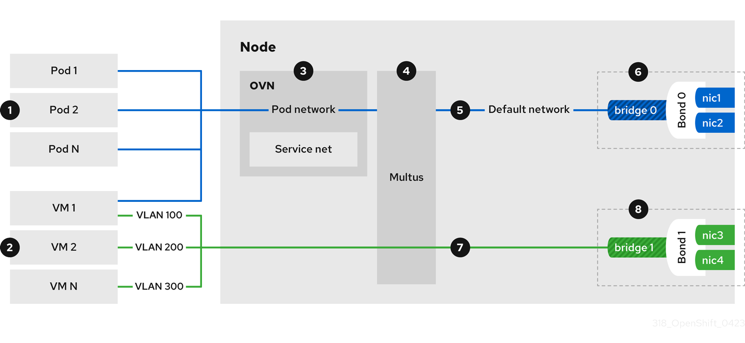
![]() Pods and VMs run on the same network infrastructure which allows you to easily connect your containerized and virtualized workloads.
Pods and VMs run on the same network infrastructure which allows you to easily connect your containerized and virtualized workloads.
![]() You can connect VMs to the default pod network and to any number of secondary networks.
You can connect VMs to the default pod network and to any number of secondary networks.
![]() The default pod network provides connectivity between all its members, service abstraction, IP management, micro segmentation, and other functionality.
The default pod network provides connectivity between all its members, service abstraction, IP management, micro segmentation, and other functionality.
![]() Multus is a "meta" CNI plugin that enables a pod or virtual machine to connect to additional network interfaces by using other compatible CNI plugins.
Multus is a "meta" CNI plugin that enables a pod or virtual machine to connect to additional network interfaces by using other compatible CNI plugins.
![]() The default pod network is overlay-based, tunneled through the underlying machine network.
The default pod network is overlay-based, tunneled through the underlying machine network.
![]() The machine network can be defined over a selected set of network interface controllers (NICs).
The machine network can be defined over a selected set of network interface controllers (NICs).
![]() Secondary VM networks are typically bridged directly to a physical network, with or without VLAN encapsulation.
Secondary VM networks are typically bridged directly to a physical network, with or without VLAN encapsulation.
![]() Secondary VM networks can be defined on dedicated set of NICs, as shown in Figure 1, or they can use the machine network.
Secondary VM networks can be defined on dedicated set of NICs, as shown in Figure 1, or they can use the machine network.
8.1.1. OpenShift Virtualization networking glossary
The following terms are used throughout OpenShift Virtualization documentation:
- Container Network Interface (CNI)
- A Cloud Native Computing Foundation project, focused on container network connectivity. OpenShift Virtualization uses CNI plugins to build upon the basic Kubernetes networking functionality.
- Multus
- A "meta" CNI plugin that allows multiple CNIs to exist so that a pod or virtual machine can use the interfaces it needs.
- Custom resource definition (CRD)
- A Kubernetes API resource that allows you to define custom resources, or an object defined by using the CRD API resource.
- Network attachment definition (NAD)
- A CRD introduced by the Multus project that allows you to attach pods, virtual machines, and virtual machine instances to one or more networks.
- Node network configuration policy (NNCP)
-
A CRD introduced by the nmstate project, describing the requested network configuration on nodes. You update the node network configuration, including adding and removing interfaces, by applying a
NodeNetworkConfigurationPolicymanifest to the cluster.
8.1.2. Using the default pod network
- Connecting a virtual machine to the default pod network
- Each VM is connected by default to the default internal pod network. You can add or remove network interfaces by editing the VM specification.
- Exposing a virtual machine as a service
-
You can expose a VM within the cluster or outside the cluster by creating a
Serviceobject. For on-premise clusters, you can configure a load balancing service by using the MetalLB Operator. You can install the MetalLB Operator by using the OpenShift Container Platform web console or the CLI.
8.1.3. Configuring VM secondary network interfaces
You can connect a virtual machine to a secondary network by using Linux bridge, SR-IOV and OVN-Kubernetes CNI plugins. You can list multiple secondary networks and interfaces in the VM specification. It is not required to specify the primary pod network in the VM specification when connecting to a secondary network interface.
- Connecting a virtual machine to a Linux bridge network
Install the Kubernetes NMState Operator to configure Linux bridges, VLANs, and bondings for your secondary networks.
You can create a Linux bridge network and attach a VM to the network by performing the following steps:
-
Configure a Linux bridge network device by creating a
NodeNetworkConfigurationPolicycustom resource definition (CRD). -
Configure a Linux bridge network by creating a
NetworkAttachmentDefinitionCRD. - Connect the VM to the Linux bridge network by including the network details in the VM configuration.
-
Configure a Linux bridge network device by creating a
- Connecting a virtual machine to an SR-IOV network
You can use Single Root I/O Virtualization (SR-IOV) network devices with additional networks on your OpenShift Container Platform cluster installed on bare metal or Red Hat OpenStack Platform (RHOSP) infrastructure for applications that require high bandwidth or low latency.
You must install the SR-IOV Network Operator on your cluster to manage SR-IOV network devices and network attachments.
You can connect a VM to an SR-IOV network by performing the following steps:
-
Configure an SR-IOV network device by creating a
SriovNetworkNodePolicyCRD. -
Configure an SR-IOV network by creating an
SriovNetworkobject. - Connect the VM to the SR-IOV network by including the network details in the VM configuration.
-
Configure an SR-IOV network device by creating a
- Connecting a virtual machine to an OVN-Kubernetes secondary network
You can connect a VM to an Open Virtual Network (OVN)-Kubernetes secondary network. OpenShift Virtualization supports the layer 2 and localnet topologies for OVN-Kubernetes.
- A layer 2 topology connects workloads by a cluster-wide logical switch. The OVN-Kubernetes Container Network Interface (CNI) plug-in uses the Geneve (Generic Network Virtualization Encapsulation) protocol to create an overlay network between nodes. You can use this overlay network to connect VMs on different nodes, without having to configure any additional physical networking infrastructure.
- A localnet topology connects the secondary network to the physical underlay. This enables both east-west cluster traffic and access to services running outside the cluster, but it requires additional configuration of the underlying Open vSwitch (OVS) system on cluster nodes.
To configure an OVN-Kubernetes secondary network and attach a VM to that network, perform the following steps:
Configure an OVN-Kubernetes secondary network by creating a network attachment definition (NAD).
NoteFor localnet topology, you must configure an OVS bridge by creating a
NodeNetworkConfigurationPolicyobject before creating the NAD.- Connect the VM to the OVN-Kubernetes secondary network by adding the network details to the VM specification.
8.1.3.1. Comparing Linux bridge CNI and OVN-Kubernetes localnet topology
The following table provides a comparison of features available when using the Linux bridge CNI versus the localnet topology for an OVN-Kubernetes plugin:
| Feature | Available on Linux bridge CNI | Available on OVN-Kubernetes localnet |
|---|---|---|
| Layer 2 access to the underlay native network | Only on secondary network interface controllers (NICs) | Yes |
| Layer 2 access to underlay VLANs | Yes | Yes |
| Layer 2 trunk access | Yes | No |
| Network policies | No | No |
| MAC spoof filtering | Yes | Yes (Always on) |
- Hot plugging secondary network interfaces
- You can add or remove secondary network interfaces without stopping your VM. OpenShift Virtualization supports hot plugging and hot unplugging for Linux bridge interfaces that use the VirtIO device driver.
- Using DPDK with SR-IOV
- The Data Plane Development Kit (DPDK) provides a set of libraries and drivers for fast packet processing. You can configure clusters and VMs to run DPDK workloads over SR-IOV networks.
- Configuring a dedicated network for live migration
- You can configure a dedicated Multus network for live migration. A dedicated network minimizes the effects of network saturation on tenant workloads during live migration.
- Accessing a virtual machine by using the cluster FQDN
- You can access a VM that is attached to a secondary network interface from outside the cluster by using its fully qualified domain name (FQDN).
- Configuring and viewing IP addresses
- You can configure an IP address of a secondary network interface when you create a VM. The IP address is provisioned with cloud-init. You can view the IP address of a VM by using the OpenShift Container Platform web console or the command line. The network information is collected by the QEMU guest agent.
8.1.4. Integrating with OpenShift Service Mesh
- Connecting a virtual machine to a service mesh
- OpenShift Virtualization is integrated with OpenShift Service Mesh. You can monitor, visualize, and control traffic between pods and virtual machines.
8.1.5. Managing MAC address pools
- Managing MAC address pools for network interfaces
- The KubeMacPool component allocates MAC addresses for VM network interfaces from a shared MAC address pool. This ensures that each network interface is assigned a unique MAC address. A virtual machine instance created from that VM retains the assigned MAC address across reboots.
8.1.6. Configuring SSH access
- Configuring SSH access to virtual machines
You can configure SSH access to VMs by using the following methods:
You create an SSH key pair, add the public key to a VM, and connect to the VM by running the
virtctl sshcommand with the private key.You can add public SSH keys to Red Hat Enterprise Linux (RHEL) 9 VMs at runtime or at first boot to VMs with guest operating systems that can be configured by using a cloud-init data source.
You add the
virtctl port-fowardcommand to your.ssh/configfile and connect to the VM by using OpenSSH.You create a service, associate the service with the VM, and connect to the IP address and port exposed by the service.
You configure a secondary network, attach a VM to the secondary network interface, and connect to its allocated IP address.
8.2. Connecting a virtual machine to the default pod network
You can connect a virtual machine to the default internal pod network by configuring its network interface to use the masquerade binding mode.
Traffic passing through network interfaces to the default pod network is interrupted during live migration.
8.2.1. Configuring masquerade mode from the command line
You can use masquerade mode to hide a virtual machine’s outgoing traffic behind the pod IP address. Masquerade mode uses Network Address Translation (NAT) to connect virtual machines to the pod network backend through a Linux bridge.
Enable masquerade mode and allow traffic to enter the virtual machine by editing your virtual machine configuration file.
Prerequisites
- The virtual machine must be configured to use DHCP to acquire IPv4 addresses.
Procedure
Edit the
interfacesspec of your virtual machine configuration file:apiVersion: kubevirt.io/v1 kind: VirtualMachine metadata: name: example-vm spec: template: spec: domain: devices: interfaces: - name: default masquerade: {}1 ports:2 - port: 80 # ... networks: - name: default pod: {}- 1
- Connect using masquerade mode.
- 2
- Optional: List the ports that you want to expose from the virtual machine, each specified by the
portfield. Theportvalue must be a number between 0 and 65536. When theportsarray is not used, all ports in the valid range are open to incoming traffic. In this example, incoming traffic is allowed on port80.
NotePorts 49152 and 49153 are reserved for use by the libvirt platform and all other incoming traffic to these ports is dropped.
Create the virtual machine:
$ oc create -f <vm-name>.yaml
8.2.2. Configuring masquerade mode with dual-stack (IPv4 and IPv6)
You can configure a new virtual machine (VM) to use both IPv6 and IPv4 on the default pod network by using cloud-init.
The Network.pod.vmIPv6NetworkCIDR field in the virtual machine instance configuration determines the static IPv6 address of the VM and the gateway IP address. These are used by the virt-launcher pod to route IPv6 traffic to the virtual machine and are not used externally. The Network.pod.vmIPv6NetworkCIDR field specifies an IPv6 address block in Classless Inter-Domain Routing (CIDR) notation. The default value is fd10:0:2::2/120. You can edit this value based on your network requirements.
When the virtual machine is running, incoming and outgoing traffic for the virtual machine is routed to both the IPv4 address and the unique IPv6 address of the virt-launcher pod. The virt-launcher pod then routes the IPv4 traffic to the DHCP address of the virtual machine, and the IPv6 traffic to the statically set IPv6 address of the virtual machine.
Prerequisites
- The OpenShift Container Platform cluster must use the OVN-Kubernetes Container Network Interface (CNI) network plugin configured for dual-stack.
Procedure
In a new virtual machine configuration, include an interface with
masqueradeand configure the IPv6 address and default gateway by using cloud-init.apiVersion: kubevirt.io/v1 kind: VirtualMachine metadata: name: example-vm-ipv6 spec: template: spec: domain: devices: interfaces: - name: default masquerade: {}1 ports: - port: 802 # ... networks: - name: default pod: {} volumes: - cloudInitNoCloud: networkData: | version: 2 ethernets: eth0: dhcp4: true addresses: [ fd10:0:2::2/120 ]3 gateway6: fd10:0:2::14 - 1
- Connect using masquerade mode.
- 2
- Allows incoming traffic on port 80 to the virtual machine.
- 3
- The static IPv6 address as determined by the
Network.pod.vmIPv6NetworkCIDRfield in the virtual machine instance configuration. The default value isfd10:0:2::2/120. - 4
- The gateway IP address as determined by the
Network.pod.vmIPv6NetworkCIDRfield in the virtual machine instance configuration. The default value isfd10:0:2::1.
Create the virtual machine in the namespace:
$ oc create -f example-vm-ipv6.yaml
Verification
- To verify that IPv6 has been configured, start the virtual machine and view the interface status of the virtual machine instance to ensure it has an IPv6 address:
$ oc get vmi <vmi-name> -o jsonpath="{.status.interfaces[*].ipAddresses}"8.2.3. About jumbo frames support
When using the OVN-Kubernetes CNI plugin, you can send unfragmented jumbo frame packets between two virtual machines (VMs) that are connected on the default pod network. Jumbo frames have a maximum transmission unit (MTU) value greater than 1500 bytes.
The VM automatically gets the MTU value of the cluster network, set by the cluster administrator, in one of the following ways:
-
libvirt: If the guest OS has the latest version of the VirtIO driver that can interpret incoming data via a Peripheral Component Interconnect (PCI) config register in the emulated device. - DHCP: If the guest DHCP client can read the MTU value from the DHCP server response.
For Windows VMs that do not have a VirtIO driver, you must set the MTU manually by using netsh or a similar tool. This is because the Windows DHCP client does not read the MTU value.
8.3. Exposing a virtual machine by using a service
You can expose a virtual machine within the cluster or outside the cluster by creating a Service object.
8.3.1. About services
A Kubernetes service exposes network access for clients to an application running on a set of pods. Services offer abstraction, load balancing, and, in the case of the NodePort and LoadBalancer types, exposure to the outside world.
- ClusterIP
-
Exposes the service on an internal IP address and as a DNS name to other applications within the cluster. A single service can map to multiple virtual machines. When a client tries to connect to the service, the client’s request is load balanced among available backends.
ClusterIPis the default service type. - NodePort
-
Exposes the service on the same port of each selected node in the cluster.
NodePortmakes a port accessible from outside the cluster, as long as the node itself is externally accessible to the client. - LoadBalancer
- Creates an external load balancer in the current cloud (if supported) and assigns a fixed, external IP address to the service.
For on-premise clusters, you can configure a load-balancing service by deploying the MetalLB Operator.
8.3.2. Dual-stack support
If IPv4 and IPv6 dual-stack networking is enabled for your cluster, you can create a service that uses IPv4, IPv6, or both, by defining the spec.ipFamilyPolicy and the spec.ipFamilies fields in the Service object.
The spec.ipFamilyPolicy field can be set to one of the following values:
- SingleStack
- The control plane assigns a cluster IP address for the service based on the first configured service cluster IP range.
- PreferDualStack
- The control plane assigns both IPv4 and IPv6 cluster IP addresses for the service on clusters that have dual-stack configured.
- RequireDualStack
-
This option fails for clusters that do not have dual-stack networking enabled. For clusters that have dual-stack configured, the behavior is the same as when the value is set to
PreferDualStack. The control plane allocates cluster IP addresses from both IPv4 and IPv6 address ranges.
You can define which IP family to use for single-stack or define the order of IP families for dual-stack by setting the spec.ipFamilies field to one of the following array values:
-
[IPv4] -
[IPv6] -
[IPv4, IPv6] -
[IPv6, IPv4]
8.3.3. Creating a service by using the command line
You can create a service and associate it with a virtual machine (VM) by using the command line.
Prerequisites
- You configured the cluster network to support the service.
Procedure
Edit the
VirtualMachinemanifest to add the label for service creation:apiVersion: kubevirt.io/v1 kind: VirtualMachine metadata: name: example-vm namespace: example-namespace spec: running: false template: metadata: labels: special: key1 # ...- 1
- Add
special: keyto thespec.template.metadata.labelsstanza.
NoteLabels on a virtual machine are passed through to the pod. The
special: keylabel must match the label in thespec.selectorattribute of theServicemanifest.-
Save the
VirtualMachinemanifest file to apply your changes. Create a
Servicemanifest to expose the VM:apiVersion: v1 kind: Service metadata: name: example-service namespace: example-namespace spec: # ... selector: special: key1 type: NodePort2 ports:3 protocol: TCP port: 80 targetPort: 9376 nodePort: 30000-
Save the
Servicemanifest file. Create the service by running the following command:
$ oc create -f example-service.yaml- Restart the VM to apply the changes.
Verification
Query the
Serviceobject to verify that it is available:$ oc get service -n example-namespace
8.4. Connecting a virtual machine to a Linux bridge network
By default, OpenShift Virtualization is installed with a single, internal pod network.
You can create a Linux bridge network and attach a virtual machine (VM) to the network by performing the following steps:
- Create a Linux bridge node network configuration policy (NNCP).
- Create a Linux bridge network attachment definition (NAD) by using the web console or the command line.
- Configure the VM to recognize the NAD by using the web console or the command line.
OpenShift Virtualization does not support Linux bridge bonding modes 0, 5, and 6. For more information, see Which bonding modes work when used with a bridge that virtual machine guests or containers connect to?.
8.4.1. Creating a Linux bridge NNCP
You can create a NodeNetworkConfigurationPolicy (NNCP) manifest for a Linux bridge network.
Prerequisites
- You have installed the Kubernetes NMState Operator.
Procedure
Create the
NodeNetworkConfigurationPolicymanifest. This example includes sample values that you must replace with your own information.apiVersion: nmstate.io/v1 kind: NodeNetworkConfigurationPolicy metadata: name: br1-eth1-policy1 spec: desiredState: interfaces: - name: br12 description: Linux bridge with eth1 as a port3 type: linux-bridge4 state: up5 ipv4: enabled: false6 bridge: options: stp: enabled: false7 port: - name: eth18 - 1
- Name of the policy.
- 2
- Name of the interface.
- 3
- Optional: Human-readable description of the interface.
- 4
- The type of interface. This example creates a bridge.
- 5
- The requested state for the interface after creation.
- 6
- Disables IPv4 in this example.
- 7
- Disables STP in this example.
- 8
- The node NIC to which the bridge is attached.
8.4.2. Creating a Linux bridge NAD
You can create a Linux bridge network attachment definition (NAD) by using the OpenShift Container Platform web console or command line.
8.4.2.1. Creating a Linux bridge NAD by using the web console
You can create a network attachment definition (NAD) to provide layer-2 networking to pods and virtual machines by using the OpenShift Container Platform web console.
A Linux bridge network attachment definition is the most efficient method for connecting a virtual machine to a VLAN.
Configuring IP address management (IPAM) in a network attachment definition for virtual machines is not supported.
Procedure
-
In the web console, click Networking
NetworkAttachmentDefinitions. Click Create Network Attachment Definition.
NoteThe network attachment definition must be in the same namespace as the pod or virtual machine.
- Enter a unique Name and optional Description.
- Select CNV Linux bridge from the Network Type list.
- Enter the name of the bridge in the Bridge Name field.
- Optional: If the resource has VLAN IDs configured, enter the ID numbers in the VLAN Tag Number field.
- Optional: Select MAC Spoof Check to enable MAC spoof filtering. This feature provides security against a MAC spoofing attack by allowing only a single MAC address to exit the pod.
- Click Create.
8.4.2.2. Creating a Linux bridge NAD by using the command line
You can create a network attachment definition (NAD) to provide layer-2 networking to pods and virtual machines (VMs) by using the command line.
The NAD and the VM must be in the same namespace.
Configuring IP address management (IPAM) in a network attachment definition for virtual machines is not supported.
Prerequisites
-
The node must support nftables and the
nftbinary must be deployed to enable MAC spoof check.
Procedure
Add the VM to the
NetworkAttachmentDefinitionconfiguration, as in the following example:apiVersion: "k8s.cni.cncf.io/v1" kind: NetworkAttachmentDefinition metadata: name: bridge-network1 annotations: k8s.v1.cni.cncf.io/resourceName: bridge.network.kubevirt.io/br12 spec: config: | { "cniVersion": "0.3.1", "name": "bridge-network",3 "type": "bridge",4 "bridge": "br1",5 "macspoofchk": false,6 "vlan": 100,7 "preserveDefaultVlan": false8 }- 1
- The name for the
NetworkAttachmentDefinitionobject. - 2
- Optional: Annotation key-value pair for node selection for the bridge configured on some nodes. If you add this annotation to your network attachment definition, your virtual machine instances will only run on the nodes that have the defined bridge connected.
- 3
- The name for the configuration. It is recommended to match the configuration name to the
namevalue of the network attachment definition. - 4
- The actual name of the Container Network Interface (CNI) plugin that provides the network for this network attachment definition. Do not change this field unless you want to use a different CNI.
- 5
- The name of the Linux bridge configured on the node. The name should match the interface bridge name defined in the
NodeNetworkConfigurationPolicymanifest. - 6
- Optional: A flag to enable the MAC spoof check. When set to
true, you cannot change the MAC address of the pod or guest interface. This attribute allows only a single MAC address to exit the pod, which provides security against a MAC spoofing attack. - 7
- Optional: The VLAN tag. No additional VLAN configuration is required on the node network configuration policy.
- 8
- Optional: Indicates whether the VM connects to the bridge through the default VLAN. The default value is
true.
NoteA Linux bridge network attachment definition is the most efficient method for connecting a virtual machine to a VLAN.
Create the network attachment definition:
$ oc create -f network-attachment-definition.yaml1 - 1
- Where
network-attachment-definition.yamlis the file name of the network attachment definition manifest.
Verification
Verify that the network attachment definition was created by running the following command:
$ oc get network-attachment-definition bridge-network
8.4.3. Configuring a VM network interface
You can configure a virtual machine (VM) network interface by using the OpenShift Container Platform web console or command line.
8.4.3.1. Configuring a VM network interface by using the web console
You can configure a network interface for a virtual machine (VM) by using the OpenShift Container Platform web console.
Prerequisites
- You created a network attachment definition for the network.
Procedure
-
Navigate to Virtualization
VirtualMachines. - Click a VM to view the VirtualMachine details page.
- On the Configuration tab, click the Network interfaces tab.
- Click Add network interface.
- Enter the interface name and select the network attachment definition from the Network list.
- Click Save.
- Restart the VM to apply the changes.
Networking fields
| Name | Description |
|---|---|
| Name | Name for the network interface controller. |
| Model | Indicates the model of the network interface controller. Supported values are e1000e and virtio. |
| Network | List of available network attachment definitions. |
| Type | List of available binding methods. Select the binding method suitable for the network interface:
|
| MAC Address | MAC address for the network interface controller. If a MAC address is not specified, one is assigned automatically. |
8.4.3.2. Configuring a VM network interface by using the command line
You can configure a virtual machine (VM) network interface for a bridge network by using the command line.
Prerequisites
- Shut down the virtual machine before editing the configuration. If you edit a running virtual machine, you must restart the virtual machine for the changes to take effect.
Procedure
Add the bridge interface and the network attachment definition to the VM configuration as in the following example:
apiVersion: kubevirt.io/v1
kind: VirtualMachine
metadata:
  name: example-vm
spec:
  template:
    spec:
      domain:
        devices:
          interfaces:
            - bridge: {}
              name: bridge-net
1 # ... networks: - name: bridge-net2 multus: networkName: a-bridge-network3 Apply the configuration:
$ oc apply -f example-vm.yaml- Optional: If you edited a running virtual machine, you must restart it for the changes to take effect.
8.5. Connecting a virtual machine to an SR-IOV network
You can connect a virtual machine (VM) to a Single Root I/O Virtualization (SR-IOV) network by performing the following steps:
8.5.1. Configuring SR-IOV network devices
The SR-IOV Network Operator adds the SriovNetworkNodePolicy.sriovnetwork.openshift.io custom resource definition (CRD) to OpenShift Container Platform. You can configure an SR-IOV network device by creating a SriovNetworkNodePolicy custom resource (CR).
When applying the configuration specified in a SriovNetworkNodePolicy object, the SR-IOV Operator might drain the nodes, and in some cases, reboot nodes.
It might take several minutes for a configuration change to apply.
Prerequisites
-
You installed the OpenShift CLI (
oc). -
You have access to the cluster as a user with the
cluster-adminrole. - You have installed the SR-IOV Network Operator.
- You have enough available nodes in your cluster to handle the evicted workload from drained nodes.
- You have not selected any control plane nodes for SR-IOV network device configuration.
Procedure
Create an
SriovNetworkNodePolicyobject, and then save the YAML in the<name>-sriov-node-network.yamlfile. Replace<name>with the name for this configuration.apiVersion: sriovnetwork.openshift.io/v1 kind: SriovNetworkNodePolicy metadata: name: <name> namespace: openshift-sriov-network-operator spec: resourceName: <sriov_resource_name> nodeSelector: feature.node.kubernetes.io/network-sriov.capable: "true" priority: <priority> mtu: <mtu> numVfs: <num> nicSelector: vendor: "<vendor_code>" deviceID: "<device_id>" pfNames: ["<pf_name>", ...] rootDevices: ["<pci_bus_id>", "..."] deviceType: vfio-pci isRdma: falsemetadata.name-
Specify a name for the
SriovNetworkNodePolicyobject. metadata.namespace- Specify the namespace where the SR-IOV Network Operator is installed.
spec.resourceName-
Specify the resource name of the SR-IOV device plugin. You can create multiple
SriovNetworkNodePolicyobjects for a resource name. spec.nodeSelector.feature.node.kubernetes.io/network-sriov.capable- Specify the node selector to select which nodes are configured. Only SR-IOV network devices on selected nodes are configured. The SR-IOV Container Network Interface (CNI) plugin and device plugin are deployed only on selected nodes.
spec.priority-
Optional: Specify an integer value between
0and99. A smaller number gets higher priority, so a priority of10is higher than a priority of99. The default value is99. spec.mtu- Optional: Specify a value for the maximum transmission unit (MTU) of the virtual function. The maximum MTU value can vary for different NIC models.
spec.numVfs-
Specify the number of the virtual functions (VF) to create for the SR-IOV physical network device. For an Intel network interface controller (NIC), the number of VFs cannot be larger than the total VFs supported by the device. For a Mellanox NIC, the number of VFs cannot be larger than
127. spec.nicSelectorThe
nicSelectormapping selects the Ethernet device for the Operator to configure. You do not need to specify values for all the parameters.NoteIt is recommended to identify the Ethernet adapter with enough precision to minimize the possibility of selecting an Ethernet device unintentionally. If you specify
rootDevices, you must also specify a value forvendor,deviceID, orpfNames.If you specify both
pfNamesandrootDevicesat the same time, ensure that they point to an identical device.spec.nicSelector.vendor-
Optional: Specify the vendor hex code of the SR-IOV network device. The only allowed values are either
8086or15b3. spec.nicSelector.deviceID-
Optional: Specify the device hex code of SR-IOV network device. The only allowed values are
158b,1015,1017. spec.nicSelector.pfNames- Optional: The parameter accepts an array of one or more physical function (PF) names for the Ethernet device.
spec.nicSelector.rootDevices-
The parameter accepts an array of one or more PCI bus addresses for the physical function of the Ethernet device. Provide the address in the following format:
0000:02:00.1. spec.deviceType-
The
vfio-pcidriver type is required for virtual functions in OpenShift Virtualization. spec.isRdmaOptional: Specify whether to enable remote direct memory access (RDMA) mode. For a Mellanox card, set
isRdmatofalse. The default value isfalse.NoteIf
isRDMAflag is set totrue, you can continue to use the RDMA enabled VF as a normal network device. A device can be used in either mode.
-
Optional: Label the SR-IOV capable cluster nodes with
SriovNetworkNodePolicy.Spec.NodeSelectorif they are not already labeled. For more information about labeling nodes, see "Understanding how to update labels on nodes". Create the
SriovNetworkNodePolicyobject:$ oc create -f <name>-sriov-node-network.yamlwhere
<name>specifies the name for this configuration.After applying the configuration update, all the pods in
sriov-network-operatornamespace transition to theRunningstatus.To verify that the SR-IOV network device is configured, enter the following command. Replace
<node_name>with the name of a node with the SR-IOV network device that you just configured.$ oc get sriovnetworknodestates -n openshift-sriov-network-operator <node_name> -o jsonpath='{.status.syncStatus}'
8.5.2. Configuring SR-IOV additional network
You can configure an additional network that uses SR-IOV hardware by creating an SriovNetwork object.
When you create an SriovNetwork object, the SR-IOV Network Operator automatically creates a NetworkAttachmentDefinition object.
Do not modify or delete an SriovNetwork object if it is attached to pods or virtual machines in a running state.
Prerequisites
-
Install the OpenShift CLI (
oc). -
Log in as a user with
cluster-adminprivileges.
Procedure
-
Create the following
SriovNetworkobject, and then save the YAML in the<name>-sriov-network.yamlfile. Replace<name>with a name for this additional network.
apiVersion: sriovnetwork.openshift.io/v1
kind: SriovNetwork
metadata:
  name: <name>
namespace: openshift-sriov-network-operator
spec:
  resourceName: <sriov_resource_name>
networkNamespace: <target_namespace>
vlan: <vlan>
spoofChk: "<spoof_check>"
linkState: <link_state>
maxTxRate: <max_tx_rate>
minTxRate: <min_rx_rate>
vlanQoS: <vlan_qos>
trust: "<trust_vf>"
capabilities: <capabilities> - 1
- Replace
<name>with a name for the object. The SR-IOV Network Operator creates aNetworkAttachmentDefinitionobject with same name. - 2
- Specify the namespace where the SR-IOV Network Operator is installed.
- 3
- Replace
<sriov_resource_name>with the value for the.spec.resourceNameparameter from theSriovNetworkNodePolicyobject that defines the SR-IOV hardware for this additional network. - 4
- Replace
<target_namespace>with the target namespace for the SriovNetwork. Only pods or virtual machines in the target namespace can attach to the SriovNetwork. - 5
- Optional: Replace
<vlan>with a Virtual LAN (VLAN) ID for the additional network. The integer value must be from0to4095. The default value is0. - 6
- Optional: Replace
<spoof_check>with the spoof check mode of the VF. The allowed values are the strings"on"and"off".ImportantYou must enclose the value you specify in quotes or the CR is rejected by the SR-IOV Network Operator.
- 7
- Optional: Replace
<link_state>with the link state of virtual function (VF). Allowed value areenable,disableandauto. - 8
- Optional: Replace
<max_tx_rate>with a maximum transmission rate, in Mbps, for the VF. - 9
- Optional: Replace
<min_tx_rate>with a minimum transmission rate, in Mbps, for the VF. This value should always be less than or equal to Maximum transmission rate.NoteIntel NICs do not support the
minTxRateparameter. For more information, see BZ#1772847. - 10
- Optional: Replace
<vlan_qos>with an IEEE 802.1p priority level for the VF. The default value is0. - 11
- Optional: Replace
<trust_vf>with the trust mode of the VF. The allowed values are the strings"on"and"off".ImportantYou must enclose the value you specify in quotes or the CR is rejected by the SR-IOV Network Operator.
- 12
- Optional: Replace
<capabilities>with the capabilities to configure for this network.
To create the object, enter the following command. Replace
<name>with a name for this additional network.$ oc create -f <name>-sriov-network.yamlOptional: To confirm that the
NetworkAttachmentDefinitionobject associated with theSriovNetworkobject that you created in the previous step exists, enter the following command. Replace<namespace>with the namespace you specified in theSriovNetworkobject.$ oc get net-attach-def -n <namespace>
8.5.3. Connecting a virtual machine to an SR-IOV network by using the command line
You can connect the virtual machine (VM) to the SR-IOV network by including the network details in the VM configuration.
Procedure
Add the SR-IOV network details to the
spec.domain.devices.interfacesandspec.networksstanzas of the VM configuration as in the following example:apiVersion: kubevirt.io/v1 kind: VirtualMachine metadata: name: example-vm spec: domain: devices: interfaces: - name: nic11 sriov: {} networks: - name: nic12 multus: networkName: sriov-network3 # ...Apply the virtual machine configuration:
$ oc apply -f <vm_sriov>.yaml1 - 1
- The name of the virtual machine YAML file.
8.5.4. Connecting a VM to an SR-IOV network by using the web console
You can connect a VM to the SR-IOV network by including the network details in the VM configuration.
Prerequisites
- You must create a network attachment definition for the network.
Procedure
-
Navigate to Virtualization
VirtualMachines. - Click a VM to view the VirtualMachine details page.
- On the Configuration tab, click the Network interfaces tab.
- Click Add network interface.
- Enter the interface name.
- Select an SR-IOV network attachment definition from the Network list.
-
Select
SR-IOVfrom the Type list. - Optional: Add a network Model or Mac address.
- Click Save.
- Restart or live-migrate the VM to apply the changes.
8.6. Using DPDK with SR-IOV
The Data Plane Development Kit (DPDK) provides a set of libraries and drivers for fast packet processing.
You can configure clusters and virtual machines (VMs) to run DPDK workloads over SR-IOV networks.
8.6.1. Configuring a cluster for DPDK workloads
You can configure an OpenShift Container Platform cluster to run Data Plane Development Kit (DPDK) workloads for improved network performance.
Prerequisites
-
You have access to the cluster as a user with
cluster-adminpermissions. -
You have installed the OpenShift CLI (
oc). - You have installed the SR-IOV Network Operator.
- You have installed the Node Tuning Operator.
Procedure
- Map your compute nodes topology to determine which Non-Uniform Memory Access (NUMA) CPUs are isolated for DPDK applications and which ones are reserved for the operating system (OS).
Label a subset of the compute nodes with a custom role; for example,
worker-dpdk:$ oc label node <node_name> node-role.kubernetes.io/worker-dpdk=""Create a new
MachineConfigPoolmanifest that contains theworker-dpdklabel in thespec.machineConfigSelectorobject:Example
MachineConfigPoolmanifestapiVersion: machineconfiguration.openshift.io/v1 kind: MachineConfigPool metadata: name: worker-dpdk labels: machineconfiguration.openshift.io/role: worker-dpdk spec: machineConfigSelector: matchExpressions: - key: machineconfiguration.openshift.io/role operator: In values: - worker - worker-dpdk nodeSelector: matchLabels: node-role.kubernetes.io/worker-dpdk: ""Create a
PerformanceProfilemanifest that applies to the labeled nodes and the machine config pool that you created in the previous steps. The performance profile specifies the CPUs that are isolated for DPDK applications and the CPUs that are reserved for house keeping.Example
PerformanceProfilemanifestapiVersion: performance.openshift.io/v2 kind: PerformanceProfile metadata: name: profile-1 spec: cpu: isolated: 4-39,44-79 reserved: 0-3,40-43 globallyDisableIrqLoadBalancing: true hugepages: defaultHugepagesSize: 1G pages: - count: 8 node: 0 size: 1G net: userLevelNetworking: true nodeSelector: node-role.kubernetes.io/worker-dpdk: "" numa: topologyPolicy: single-numa-nodeNoteThe compute nodes automatically restart after you apply the
MachineConfigPoolandPerformanceProfilemanifests.Retrieve the name of the generated
RuntimeClassresource from thestatus.runtimeClassfield of thePerformanceProfileobject:$ oc get performanceprofiles.performance.openshift.io profile-1 -o=jsonpath='{.status.runtimeClass}{"\n"}'Set the previously obtained
RuntimeClassname as the default container runtime class for thevirt-launcherpods by editing theHyperConvergedcustom resource (CR):$ oc patch hyperconverged kubevirt-hyperconverged -n openshift-cnv \ --type='json' -p='[{"op": "add", "path": "/spec/defaultRuntimeClass", "value":"<runtimeclass-name>"}]'NoteEditing the
HyperConvergedCR changes a global setting that affects all VMs that are created after the change is applied.If your DPDK-enabled compute nodes use Simultaneous multithreading (SMT), enable the
AlignCPUsenabler by editing theHyperConvergedCR:$ oc patch hyperconverged kubevirt-hyperconverged -n openshift-cnv \ --type='json' -p='[{"op": "replace", "path": "/spec/featureGates/alignCPUs", "value": true}]'NoteEnabling
AlignCPUsallows OpenShift Virtualization to request up to two additional dedicated CPUs to bring the total CPU count to an even parity when using emulator thread isolation.Create an
SriovNetworkNodePolicyobject with thespec.deviceTypefield set tovfio-pci:Example
SriovNetworkNodePolicymanifestapiVersion: sriovnetwork.openshift.io/v1 kind: SriovNetworkNodePolicy metadata: name: policy-1 namespace: openshift-sriov-network-operator spec: resourceName: intel_nics_dpdk deviceType: vfio-pci mtu: 9000 numVfs: 4 priority: 99 nicSelector: vendor: "8086" deviceID: "1572" pfNames: - eno3 rootDevices: - "0000:19:00.2" nodeSelector: feature.node.kubernetes.io/network-sriov.capable: "true"
8.6.2. Configuring a project for DPDK workloads
You can configure the project to run DPDK workloads on SR-IOV hardware.
Prerequisites
- Your cluster is configured to run DPDK workloads.
Procedure
Create a namespace for your DPDK applications:
$ oc create ns dpdk-checkup-nsCreate an
SriovNetworkobject that references theSriovNetworkNodePolicyobject. When you create anSriovNetworkobject, the SR-IOV Network Operator automatically creates aNetworkAttachmentDefinitionobject.Example
SriovNetworkmanifestapiVersion: sriovnetwork.openshift.io/v1 kind: SriovNetwork metadata: name: dpdk-sriovnetwork namespace: openshift-sriov-network-operator spec: ipam: | { "type": "host-local", "subnet": "10.56.217.0/24", "rangeStart": "10.56.217.171", "rangeEnd": "10.56.217.181", "routes": [{ "dst": "0.0.0.0/0" }], "gateway": "10.56.217.1" } networkNamespace: dpdk-checkup-ns1 resourceName: intel_nics_dpdk2 spoofChk: "off" trust: "on" vlan: 1019- Optional: Run the virtual machine latency checkup to verify that the network is properly configured.
- Optional: Run the DPDK checkup to verify that the namespace is ready for DPDK workloads.
8.6.3. Configuring a virtual machine for DPDK workloads
You can run Data Packet Development Kit (DPDK) workloads on virtual machines (VMs) to achieve lower latency and higher throughput for faster packet processing in the user space. DPDK uses the SR-IOV network for hardware-based I/O sharing.
Prerequisites
- Your cluster is configured to run DPDK workloads.
- You have created and configured the project in which the VM will run.
Procedure
Edit the
VirtualMachinemanifest to include information about the SR-IOV network interface, CPU topology, CRI-O annotations, and huge pages:Example
VirtualMachinemanifestapiVersion: kubevirt.io/v1 kind: VirtualMachine metadata: name: rhel-dpdk-vm spec: running: true template: metadata: annotations: cpu-load-balancing.crio.io: disable1 cpu-quota.crio.io: disable2 irq-load-balancing.crio.io: disable3 spec: domain: cpu: sockets: 14 cores: 55 threads: 2 dedicatedCpuPlacement: true isolateEmulatorThread: true interfaces: - masquerade: {} name: default - model: virtio name: nic-east pciAddress: '0000:07:00.0' sriov: {} networkInterfaceMultiqueue: true rng: {} memory: hugepages: pageSize: 1Gi6 guest: 8Gi networks: - name: default pod: {} - multus: networkName: dpdk-net7 name: nic-east # ...- 1
- This annotation specifies that load balancing is disabled for CPUs that are used by the container.
- 2
- This annotation specifies that the CPU quota is disabled for CPUs that are used by the container.
- 3
- This annotation specifies that Interrupt Request (IRQ) load balancing is disabled for CPUs that are used by the container.
- 4
- The number of sockets inside the VM. This field must be set to
1for the CPUs to be scheduled from the same Non-Uniform Memory Access (NUMA) node. - 5
- The number of cores inside the VM. This must be a value greater than or equal to
1. In this example, the VM is scheduled with 5 hyper-threads or 10 CPUs. - 6
- The size of the huge pages. The possible values for x86-64 architecture are 1Gi and 2Mi. In this example, the request is for 8 huge pages of size 1Gi.
- 7
- The name of the SR-IOV
NetworkAttachmentDefinitionobject.
- Save and exit the editor.
Apply the
VirtualMachinemanifest:$ oc apply -f <file_name>.yamlConfigure the guest operating system. The following example shows the configuration steps for RHEL 8 OS:
Configure huge pages by using the GRUB bootloader command-line interface. In the following example, 8 1G huge pages are specified.
$ grubby --update-kernel=ALL --args="default_hugepagesz=1GB hugepagesz=1G hugepages=8"To achieve low-latency tuning by using the
cpu-partitioningprofile in the TuneD application, run the following commands:$ dnf install -y tuned-profiles-cpu-partitioning$ echo isolated_cores=2-9 > /etc/tuned/cpu-partitioning-variables.confThe first two CPUs (0 and 1) are set aside for house keeping tasks and the rest are isolated for the DPDK application.
$ tuned-adm profile cpu-partitioningOverride the SR-IOV NIC driver by using the
driverctldevice driver control utility:$ dnf install -y driverctl$ driverctl set-override 0000:07:00.0 vfio-pci
- Restart the VM to apply the changes.
8.7. Connecting a virtual machine to an OVN-Kubernetes secondary network
You can connect a virtual machine (VM) to an Open Virtual Network (OVN)-Kubernetes secondary network. OpenShift Virtualization supports the layer 2 and localnet topologies for OVN-Kubernetes.
- A layer 2 topology connects workloads by a cluster-wide logical switch. The OVN-Kubernetes Container Network Interface (CNI) plug-in uses the Geneve (Generic Network Virtualization Encapsulation) protocol to create an overlay network between nodes. You can use this overlay network to connect VMs on different nodes, without having to configure any additional physical networking infrastructure.
- A localnet topology connects the secondary network to the physical underlay. This enables both east-west cluster traffic and access to services running outside the cluster, but it requires additional configuration of the underlying Open vSwitch (OVS) system on cluster nodes.
An OVN-Kubernetes secondary network is compatible with the multi-network policy API which provides the MultiNetworkPolicy custom resource definition (CRD) to control traffic flow to and from VMs. You can use the ipBlock attribute to define network policy ingress and egress rules for specific CIDR blocks.
To configure an OVN-Kubernetes secondary network and attach a VM to that network, perform the following steps:
Configure an OVN-Kubernetes secondary network by creating a network attachment definition (NAD).
NoteFor localnet topology, you must configure an OVS bridge by creating a
NodeNetworkConfigurationPolicyobject before creating the NAD.- Connect the VM to the OVN-Kubernetes secondary network by adding the network details to the VM specification.
8.7.1. Creating an OVN-Kubernetes NAD
You can create an OVN-Kubernetes layer 2 or localnet network attachment definition (NAD) by using the OpenShift Container Platform web console or the CLI.
Configuring IP address management (IPAM) by specifying the spec.config.ipam.subnet attribute in a network attachment definition for virtual machines is not supported.
8.7.1.1. Creating a NAD for layer 2 topology by using the CLI
You can create a network attachment definition (NAD) which describes how to attach a pod to the layer 2 overlay network.
Prerequisites
-
You have access to the cluster as a user with
cluster-adminprivileges. -
You have installed the OpenShift CLI (
oc).
Procedure
Create a
NetworkAttachmentDefinitionobject:apiVersion: k8s.cni.cncf.io/v1 kind: NetworkAttachmentDefinition metadata: name: l2-network namespace: my-namespace spec: config: |2 { "cniVersion": "0.3.1",1 "name": "my-namespace-l2-network",2 "type": "ovn-k8s-cni-overlay",3 "topology":"layer2",4 "mtu": 1400,5 "netAttachDefName": "my-namespace/l2-network"6 }- 1
- The Container Network Interface (CNI) specification version. The required value is
0.3.1. - 2
- The name of the network. This attribute is not namespaced. For example, you can have a network named
l2-networkreferenced from two differentNetworkAttachmentDefinitionobjects that exist in two different namespaces. This feature is useful to connect VMs in different namespaces. - 3
- The name of the CNI plugin. The required value is
ovn-k8s-cni-overlay. - 4
- The topological configuration for the network. The required value is
layer2. - 5
- Optional: The maximum transmission unit (MTU) value. If you do not set a value, the Cluster Network Operator (CNO) sets a default MTU value by calculating the difference among the underlay MTU of the primary network interface, the overlay MTU of the pod network, such as the Geneve (Generic Network Virtualization Encapsulation), and byte capacity of any enabled features, such as IPsec.
- 6
- The value of the
namespaceandnamefields in themetadatastanza of theNetworkAttachmentDefinitionobject.
NoteThe previous example configures a cluster-wide overlay without a subnet defined. This means that the logical switch implementing the network only provides layer 2 communication. You must configure an IP address when you create the virtual machine by either setting a static IP address or by deploying a DHCP server on the network for a dynamic IP address.
Apply the manifest by running the following command:
$ oc apply -f <filename>.yaml
8.7.1.2. Creating a NAD for localnet topology using the CLI
You can create a network attachment definition (NAD) which describes how to attach a pod to the underlying physical network.
Prerequisites
-
You have access to the cluster as a user with
cluster-adminprivileges. -
You have installed the OpenShift CLI (
oc). - You have installed the Kubernetes NMState Operator.
-
You have created a
NodeNetworkConfigurationPolicyobject to map the OVN-Kubernetes secondary network to an Open vSwitch (OVS) bridge.
Procedure
Create a
NodeNetworkConfigurationPolicyobject to map the OVN-Kubernetes secondary network to an Open vSwitch (OVS) bridge:apiVersion: nmstate.io/v1 kind: NodeNetworkConfigurationPolicy metadata: name: mapping1 spec: nodeSelector: node-role.kubernetes.io/worker: ''2 desiredState: ovn: bridge-mappings: - localnet: localnet-network3 bridge: br-ex4 state: present5 - 1
- The name of the configuration object.
- 2
- Specifies the nodes to which the node network configuration policy is to be applied. The recommended node selector value is
node-role.kubernetes.io/worker: ''. - 3
- The name of the additional network from which traffic is forwarded to the OVS bridge. This attribute must match the value of the
spec.config.physicalNetworkNamefield of theNetworkAttachmentDefinitionobject that defines the OVN-Kubernetes additional network. - 4
- The name of the OVS bridge on the node. This value is required if the
stateattribute ispresent. - 5
- The state of the mapping. Must be either
presentto add the mapping orabsentto remove the mapping. The default value ispresent.
NoteOpenShift Virtualization does not support Linux bridge bonding modes 0, 5, and 6. For more information, see Which bonding modes work when used with a bridge that virtual machine guests or containers connect to?.
Create a
NetworkAttachmentDefinitionobject:apiVersion: k8s.cni.cncf.io/v1 kind: NetworkAttachmentDefinition metadata: name: localnet-network namespace: default spec: config: |2 { "cniVersion": "0.3.1",1 "name": "localnet1",2 "type": "ovn-k8s-cni-overlay",3 "topology": "localnet",4 "physicalNetworkName": "localnet-network",5 "mtu": 1500,6 "vlanID": 200,7 "netAttachDefName": "default/localnet-network"8 }- 1
- The CNI specification version. The required value is
0.3.1. - 2
- The name of the network.
- 3
- The name of the CNI plug-in to be configured. The required value is
ovn-k8s-cni-overlay. - 4
- The topological configuration for the network. The required value is
localnet. - 5
- The name of the host’s physical network interface, to which the pod’s new network interface will be attached. This setting can be reused by multiple NADs. Note that
physicalNetworkNamemust match the value of thespec.desiredState.ovn.bridge-mappings.localnetfield of theNodeNetworkConfigurationPolicyobject that defines the OVS bridge mapping. - 6
- Optional: The maximum transmission unit (MTU) value. If you do not set a value, the Cluster Network Operator (CNO) sets a default MTU value by calculating the difference between the underlay MTU of the primary network interface, the overlay MTU of the pod network, and the byte capacity of any enabled features, such as IPsec encryption.
- 7
- Optional: The virtual LAN (VLAN) ID for the NAD. VMs that use this NAD have an interface that can communicate only with devices that use the same VLAN ID. In this example, the VLAN ID is
200. - 8
- The value of the
namespaceandnamefields in themetadatastanza of theNetworkAttachmentDefinitionobject.
Apply the manifest:
$ oc apply -f <filename>.yaml
8.7.1.3. Creating a NAD for layer 2 topology by using the web console
You can create a network attachment definition (NAD) that describes how to attach a pod to the layer 2 overlay network.
Prerequisites
-
You have access to the cluster as a user with
cluster-adminprivileges.
Procedure
-
Go to Networking
NetworkAttachmentDefinitions in the web console. - Click Create Network Attachment Definition. The network attachment definition must be in the same namespace as the pod or virtual machine using it.
- Enter a unique Name and optional Description.
- Select OVN Kubernetes L2 overlay network from the Network Type list.
- Click Create.
8.7.1.4. Creating a NAD for localnet topology using the web console
You can create a network attachment definition (NAD) to connect workloads to a physical network by using the OpenShift Container Platform web console.
Prerequisites
-
You have access to the cluster as a user with
cluster-adminprivileges. -
Use
nmstateto configure the localnet to OVS bridge mappings.
Procedure
-
Navigate to Networking
NetworkAttachmentDefinitions in the web console. - Click Create Network Attachment Definition. The network attachment definition must be in the same namespace as the pod or virtual machine using it.
- Enter a unique Name and optional Description.
- Select OVN Kubernetes secondary localnet network from the Network Type list.
- Enter the name of your pre-configured localnet identifier in the Bridge mapping field.
- Optional: You can explicitly set MTU to the specified value. The default value is chosen by the kernel.
- Optional: Encapsulate the traffic in a VLAN. The default value is none.
- Click Create.
8.7.2. Attaching a virtual machine to the OVN-Kubernetes secondary network
You can attach a virtual machine (VM) to the OVN-Kubernetes secondary network interface by using the OpenShift Container Platform web console or the CLI.
8.7.2.1. Attaching a virtual machine to an OVN-Kubernetes secondary network using the CLI
You can connect a virtual machine (VM) to the OVN-Kubernetes secondary network by including the network details in the VM configuration.
Prerequisites
-
You have access to the cluster as a user with
cluster-adminprivileges. -
You have installed the OpenShift CLI (
oc).
Procedure
Edit the
VirtualMachinemanifest to add the OVN-Kubernetes secondary network interface details, as in the following example:apiVersion: kubevirt.io/v1 kind: VirtualMachine metadata: name: vm-server spec: running: true template: spec: domain: devices: interfaces: - name: secondary1 bridge: {} resources: requests: memory: 1024Mi networks: - name: secondary2 multus: networkName: <nad_name>3 # ...Apply the
VirtualMachinemanifest:$ oc apply -f <filename>.yaml- Optional: If you edited a running virtual machine, you must restart it for the changes to take effect.
8.8. Hot plugging secondary network interfaces
You can add or remove secondary network interfaces without stopping your virtual machine (VM). OpenShift Virtualization supports hot plugging for secondary interfaces that use bridge binding and the VirtIO device driver. OpenShift Virtualization also supports hot plugging secondary interfaces that use SR-IOV binding.
Hot unplugging is not supported for Single Root I/O Virtualization (SR-IOV) interfaces.
8.8.1. VirtIO limitations
Each VirtIO interface uses one of the limited Peripheral Connect Interface (PCI) slots in the VM. There are a total of 32 slots available. The PCI slots are also used by other devices and must be reserved in advance, therefore slots might not be available on demand. OpenShift Virtualization reserves up to four slots for hot plugging interfaces. This includes any existing plugged network interfaces. For example, if your VM has two existing plugged interfaces, you can hot plug two more network interfaces.
The actual number of slots available for hot plugging also depends on the machine type. For example, the default PCI topology for the q35 machine type supports hot plugging one additional PCIe device. For more information on PCI topology and hot plug support, see the libvirt documentation.
If you restart the VM after hot plugging an interface, that interface becomes part of the standard network interfaces.
8.8.2. Hot plugging a secondary network interface by using the CLI
Hot plug a secondary network interface to a virtual machine (VM) while the VM is running.
Prerequisites
- A network attachment definition is configured in the same namespace as your VM.
- The VM to which you want to hot plug the network interface is running.
-
You have installed the
virtctltool. -
You have permission to create and list
VirtualMachineInstanceMigrationobjects. -
You have installed the OpenShift CLI (
oc).
Procedure
Use your preferred text editor to edit the
VirtualMachinemanifest, as shown in the following example:Example VM configuration
apiVersion: kubevirt.io/v1
kind: VirtualMachine
metadata:
  name: vm-fedora
template:
  spec:
    domain:
      devices:
        interfaces:
        - name: defaultnetwork
          masquerade: {}
        # new interface
        - name: <secondary_nic>
1 bridge: {} networks: - name: defaultnetwork pod: {} # new network - name: <secondary_nic>2 multus: networkName: <nad_name>3 # ...To attach the network interface to the running VM, live migrate the VM by running the following command:
$ virtctl migrate <vm_name>
Verification
Verify that the VM live migration is successful by using the following command:
$ oc get VirtualMachineInstanceMigration -wExample output
NAME                        PHASE             VMI
kubevirt-migrate-vm-lj62q   Scheduling        vm-fedora
kubevirt-migrate-vm-lj62q   Scheduled         vm-fedora
kubevirt-migrate-vm-lj62q   PreparingTarget   vm-fedora
kubevirt-migrate-vm-lj62q   TargetReady       vm-fedora
kubevirt-migrate-vm-lj62q   Running           vm-fedora
kubevirt-migrate-vm-lj62q   Succeeded         vm-fedora
Verify that the new interface is added to the VM by checking the VMI status:
$ oc get vmi vm-fedora -ojsonpath="{ @.status.interfaces }"Example output
[
  {
    "infoSource": "domain, guest-agent",
    "interfaceName": "eth0",
    "ipAddress": "10.130.0.195",
    "ipAddresses": [
      "10.130.0.195",
      "fd02:0:0:3::43c"
    ],
    "mac": "52:54:00:0e:ab:25",
    "name": "default",
    "queueCount": 1
  },
  {
    "infoSource": "domain, guest-agent, multus-status",
    "interfaceName": "eth1",
    "mac": "02:d8:b8:00:00:2a",
    "name": "bridge-interface",
1 "queueCount": 1 } ]- 1
- The hot plugged interface appears in the VMI status.
8.8.3. Hot unplugging a secondary network interface by using the CLI
You can remove a secondary network interface from a running virtual machine (VM).
Hot unplugging is not supported for Single Root I/O Virtualization (SR-IOV) interfaces.
Prerequisites
- Your VM must be running.
- The VM must be created on a cluster running OpenShift Virtualization 4.14 or later.
- The VM must have a bridge network interface attached.
Procedure
Edit the VM specification to hot unplug a secondary network interface. Setting the interface state to
absentdetaches the network interface from the guest, but the interface still exists in the pod.$ oc edit vm <vm_name>Example VM configuration
apiVersion: kubevirt.io/v1
kind: VirtualMachine
metadata:
  name: vm-fedora
template:
  spec:
    domain:
      devices:
        interfaces:
          - name: defaultnetwork
            masquerade: {}
          # set the interface state to absent
          - name: <secondary_nic>
            state: absent
1 bridge: {} networks: - name: defaultnetwork pod: {} - name: <secondary_nic> multus: networkName: <nad_name> # ...- 1
- Set the interface state to
absentto detach it from the running VM. Removing the interface details from the VM specification does not hot unplug the secondary network interface.
Remove the interface from the pod by migrating the VM:
$ virtctl migrate <vm_name>
8.9. Connecting a virtual machine to a service mesh
OpenShift Virtualization is now integrated with OpenShift Service Mesh. You can monitor, visualize, and control traffic between pods that run virtual machine workloads on the default pod network with IPv4.
8.9.1. Adding a virtual machine to a service mesh
To add a virtual machine (VM) workload to a service mesh, enable automatic sidecar injection in the VM configuration file by setting the sidecar.istio.io/inject annotation to true. Then expose your VM as a service to view your application in the mesh.
To avoid port conflicts, do not use ports used by the Istio sidecar proxy. These include ports 15000, 15001, 15006, 15008, 15020, 15021, and 15090.
Prerequisites
- You installed the Service Mesh Operators.
- You created the Service Mesh control plane.
- You added the VM project to the Service Mesh member roll.
Procedure
Edit the VM configuration file to add the
sidecar.istio.io/inject: "true"annotation:Example configuration file
apiVersion: kubevirt.io/v1
kind: VirtualMachine
metadata:
  labels:
    kubevirt.io/vm: vm-istio
  name: vm-istio
spec:
  runStrategy: Always
  template:
    metadata:
      labels:
        kubevirt.io/vm: vm-istio
        app: vm-istio
1 annotations: sidecar.istio.io/inject: "true"2 spec: domain: devices: interfaces: - name: default masquerade: {}3 disks: - disk: bus: virtio name: containerdisk - disk: bus: virtio name: cloudinitdisk resources: requests: memory: 1024M networks: - name: default pod: {} terminationGracePeriodSeconds: 180 volumes: - containerDisk: image: registry:5000/kubevirt/fedora-cloud-container-disk-demo:devel name: containerdiskApply the VM configuration:
$ oc apply -f <vm_name>.yaml1 - 1
- The name of the virtual machine YAML file.
Create a
Serviceobject to expose your VM to the service mesh.apiVersion: v1 kind: Service metadata: name: vm-istio spec: selector: app: vm-istio1 ports: - port: 8080 name: http protocol: TCP- 1
- The service selector that determines the set of pods targeted by a service. This attribute corresponds to the
spec.metadata.labelsfield in the VM configuration file. In the above example, theServiceobject namedvm-istiotargets TCP port 8080 on any pod with the labelapp=vm-istio.
Create the service:
$ oc create -f <service_name>.yaml1 - 1
- The name of the service YAML file.
8.10. Configuring a dedicated network for live migration
You can configure a dedicated Multus network for live migration. A dedicated network minimizes the effects of network saturation on tenant workloads during live migration.
8.10.1. Configuring a dedicated secondary network for live migration
To configure a dedicated secondary network for live migration, you must first create a bridge network attachment definition (NAD) by using the CLI. Then, you add the name of the NetworkAttachmentDefinition object to the HyperConverged custom resource (CR).
Prerequisites
-
You installed the OpenShift CLI (
oc). -
You logged in to the cluster as a user with the
cluster-adminrole. - Each node has at least two Network Interface Cards (NICs).
- The NICs for live migration are connected to the same VLAN.
Procedure
Create a
NetworkAttachmentDefinitionmanifest according to the following example:Example configuration file
apiVersion: "k8s.cni.cncf.io/v1"
kind: NetworkAttachmentDefinition
metadata:
  name: my-secondary-network
1 namespace: openshift-cnv2 spec: config: '{ "cniVersion": "0.3.1", "name": "migration-bridge", "type": "macvlan", "master": "eth1",3 "mode": "bridge", "ipam": { "type": "whereabouts",4 "range": "10.200.5.0/24"5 } }'- 1
- Specify the name of the
NetworkAttachmentDefinitionobject. - 2 3
- Specify the name of the NIC to be used for live migration.
- 4
- Specify the name of the CNI plugin that provides the network for the NAD.
- 5
- Specify an IP address range for the secondary network. This range must not overlap the IP addresses of the main network.
Open the
HyperConvergedCR in your default editor by running the following command:$ oc edit hyperconverged kubevirt-hyperconverged -n openshift-cnvAdd the name of the
NetworkAttachmentDefinitionobject to thespec.liveMigrationConfigstanza of theHyperConvergedCR:Example
HyperConvergedmanifestapiVersion: hco.kubevirt.io/v1beta1 kind: HyperConverged metadata: name: kubevirt-hyperconverged namespace: openshift-cnv spec: liveMigrationConfig: completionTimeoutPerGiB: 800 network: <network>1 parallelMigrationsPerCluster: 5 parallelOutboundMigrationsPerNode: 2 progressTimeout: 150 # ...- 1
- Specify the name of the Multus
NetworkAttachmentDefinitionobject to be used for live migrations.
-
Save your changes and exit the editor. The
virt-handlerpods restart and connect to the secondary network.
Verification
When the node that the virtual machine runs on is placed into maintenance mode, the VM automatically migrates to another node in the cluster. You can verify that the migration occurred over the secondary network and not the default pod network by checking the target IP address in the virtual machine instance (VMI) metadata.
$ oc get vmi <vmi_name> -o jsonpath='{.status.migrationState.targetNodeAddress}'
8.10.2. Selecting a dedicated network by using the web console
You can select a dedicated network for live migration by using the OpenShift Container Platform web console.
Prerequisites
- You configured a Multus network for live migration.
- You created a network attachment definition for the network.
Procedure
- Navigate to Virtualization > Overview in the OpenShift Container Platform web console.
- Click the Settings tab and then click Live migration.
- Select the network from the Live migration network list.
8.11. Configuring and viewing IP addresses
You can configure an IP address when you create a virtual machine (VM). The IP address is provisioned with cloud-init.
You can view the IP address of a VM by using the OpenShift Container Platform web console or the command line. The network information is collected by the QEMU guest agent.
8.11.1. Configuring IP addresses for virtual machines
You can configure a static IP address when you create a virtual machine (VM) by using the web console or the command line.
You can configure a dynamic IP address when you create a VM by using the command line.
The IP address is provisioned with cloud-init.
8.11.1.1. Configuring a static IP address when creating a virtual machine by using the web console
You can configure a static IP address when you create a virtual machine (VM) by using the web console. The IP address is provisioned with cloud-init.
If the VM is connected to the pod network, the pod network interface is the default route unless you update it.
Prerequisites
- The virtual machine is connected to a secondary network.
Procedure
-
Navigate to Virtualization
Catalog in the web console. - Click a template tile.
- Click Customize VirtualMachine.
- Click Next.
- On the Scripts tab, click the edit icon beside Cloud-init.
- Select the Add network data checkbox.
- Enter the ethernet name, one or more IP addresses separated by commas, and the gateway address.
- Click Apply.
- Click Create VirtualMachine.
8.11.1.2. Configuring an IP address when creating a virtual machine by using the command line
You can configure a static or dynamic IP address when you create a virtual machine (VM). The IP address is provisioned with cloud-init.
If the VM is connected to the pod network, the pod network interface is the default route unless you update it.
Prerequisites
- The virtual machine is connected to a secondary network.
- You have a DHCP server available on the secondary network to configure a dynamic IP for the virtual machine.
Procedure
Edit the
spec.template.spec.volumes.cloudInitNoCloud.networkDatastanza of the virtual machine configuration:To configure a dynamic IP address, specify the interface name and enable DHCP:
kind: VirtualMachine
spec:
# ...
  template:
  # ...
    spec:
      volumes:
      - cloudInitNoCloud:
          networkData: |
            version: 2
            ethernets:
              eth1:
1 dhcp4: true- 1
- Specify the interface name.
To configure a static IP, specify the interface name and the IP address:
kind: VirtualMachine
spec:
# ...
  template:
  # ...
    spec:
      volumes:
      - cloudInitNoCloud:
          networkData: |
            version: 2
            ethernets:
              eth1:
1 addresses: - 10.10.10.14/242
8.11.2. Viewing IP addresses of virtual machines
You can view the IP address of a VM by using the OpenShift Container Platform web console or the command line.
The network information is collected by the QEMU guest agent.
8.11.2.1. Viewing the IP address of a virtual machine by using the web console
You can view the IP address of a virtual machine (VM) by using the OpenShift Container Platform web console.
You must install the QEMU guest agent on a VM to view the IP address of a secondary network interface. A pod network interface does not require the QEMU guest agent.
Procedure
-
In the OpenShift Container Platform console, click Virtualization
VirtualMachines from the side menu. - Select a VM to open the VirtualMachine details page.
- Click the Details tab to view the IP address.
8.11.2.2. Viewing the IP address of a virtual machine by using the command line
You can view the IP address of a virtual machine (VM) by using the command line.
You must install the QEMU guest agent on a VM to view the IP address of a secondary network interface. A pod network interface does not require the QEMU guest agent.
Procedure
Obtain the virtual machine instance configuration by running the following command:
$ oc describe vmi <vmi_name>Example output
# ...
Interfaces:
   Interface Name:  eth0
   Ip Address:      10.244.0.37/24
   Ip Addresses:
     10.244.0.37/24
     fe80::858:aff:fef4:25/64
   Mac:             0a:58:0a:f4:00:25
   Name:            default
   Interface Name:  v2
   Ip Address:      1.1.1.7/24
   Ip Addresses:
     1.1.1.7/24
     fe80::f4d9:70ff:fe13:9089/64
   Mac:             f6:d9:70:13:90:89
   Interface Name:  v1
   Ip Address:      1.1.1.1/24
   Ip Addresses:
     1.1.1.1/24
     1.1.1.2/24
     1.1.1.4/24
     2001:de7:0:f101::1/64
     2001:db8:0:f101::1/64
     fe80::1420:84ff:fe10:17aa/64
   Mac:             16:20:84:10:17:aa
8.12. Accessing a virtual machine by using the cluster FQDN
You can access a virtual machine (VM) that is attached to a secondary network interface from outside the cluster by using the fully qualified domain name (FQDN) of the cluster.
Accessing VMs by using the cluster FQDN is a Technology Preview feature only. Technology Preview features are not supported with Red Hat production service level agreements (SLAs) and might not be functionally complete. Red Hat does not recommend using them in production. These features provide early access to upcoming product features, enabling customers to test functionality and provide feedback during the development process.
For more information about the support scope of Red Hat Technology Preview features, see Technology Preview Features Support Scope.
8.12.1. Configuring a DNS server for secondary networks
The Cluster Network Addons Operator (CNAO) deploys a Domain Name Server (DNS) server and monitoring components when you enable the deployKubeSecondaryDNS feature gate in the HyperConverged custom resource (CR).
Prerequisites
-
You installed the OpenShift CLI (
oc). - You configured a load balancer for the cluster.
-
You logged in to the cluster with
cluster-adminpermissions.
Procedure
Edit the
HyperConvergedCR in your default editor by running the following command:$ oc edit hyperconverged kubevirt-hyperconverged -n openshift-cnvEnable the DNS server and monitoring components according to the following example:
apiVersion: hco.kubevirt.io/v1beta1
kind: HyperConverged
metadata:
  name: kubevirt-hyperconverged
  namespace: openshift-cnv
spec:
    featureGates:
      deployKubeSecondaryDNS: true
1 # ...- 1
- Enables the DNS server
- Save the file and exit the editor.
Create a load balancer service to expose the DNS server outside the cluster by running the
oc exposecommand according to the following example:$ oc expose -n openshift-cnv deployment/secondary-dns --name=dns-lb \ --type=LoadBalancer --port=53 --target-port=5353 --protocol='UDP'Retrieve the external IP address by running the following command:
$ oc get service -n openshift-cnvExample output
NAME       TYPE             CLUSTER-IP     EXTERNAL-IP      PORT(S)          AGE
dns-lb     LoadBalancer     172.30.27.5    10.46.41.94      53:31829/TCP     5s
Edit the
HyperConvergedCR again:$ oc edit hyperconverged kubevirt-hyperconverged -n openshift-cnvAdd the external IP address that you previously retrieved to the
kubeSecondaryDNSNameServerIPfield in the enterprise DNS server records. For example:apiVersion: hco.kubevirt.io/v1beta1 kind: HyperConverged metadata: name: kubevirt-hyperconverged namespace: openshift-cnv spec: featureGates: deployKubeSecondaryDNS: true kubeSecondaryDNSNameServerIP: "10.46.41.94"1 # ...- 1
- Specify the external IP address exposed by the load balancer service.
- Save the file and exit the editor.
Retrieve the cluster FQDN by running the following command:
$ oc get dnses.config.openshift.io cluster -o jsonpath='{.spec.baseDomain}'Example output
openshift.example.comPoint to the DNS server. To do so, add the
kubeSecondaryDNSNameServerIPvalue and the cluster FQDN to the enterprise DNS server records. For example:vm.<FQDN>. IN NS ns.vm.<FQDN>.ns.vm.<FQDN>. IN A <kubeSecondaryDNSNameServerIP>
8.12.2. Connecting to a VM on a secondary network by using the cluster FQDN
You can access a running virtual machine (VM) attached to a secondary network interface by using the fully qualified domain name (FQDN) of the cluster.
Prerequisites
- You installed the QEMU guest agent on the VM.
- The IP address of the VM is public.
- You configured the DNS server for secondary networks.
You retrieved the fully qualified domain name (FQDN) of the cluster.
To obtain the FQDN, use the
oc getcommand as follows:$ oc get dnses.config.openshift.io cluster -o json | jq .spec.baseDomain
Procedure
Retrieve the network interface name from the VM configuration by running the following command:
$ oc get vm -n <namespace> <vm_name> -o yamlExample output
apiVersion: kubevirt.io/v1
kind: VirtualMachine
metadata:
  name: example-vm
  namespace: example-namespace
spec:
  running: true
  template:
    spec:
      domain:
        devices:
          interfaces:
            - bridge: {}
              name: example-nic
# ...
      networks:
      - multus:
          networkName: bridge-conf
        name: example-nic
1 - 1
- Note the name of the network interface.
Connect to the VM by using the
sshcommand:$ ssh <user_name>@<interface_name>.<vm_name>.<namespace>.vm.<cluster_fqdn>
8.13. Managing MAC address pools for network interfaces
The KubeMacPool component allocates MAC addresses for virtual machine (VM) network interfaces from a shared MAC address pool. This ensures that each network interface is assigned a unique MAC address.
A virtual machine instance created from that VM retains the assigned MAC address across reboots.
KubeMacPool does not handle virtual machine instances created independently from a virtual machine.
8.13.1. Managing KubeMacPool by using the command line
You can disable and re-enable KubeMacPool by using the command line.
KubeMacPool is enabled by default.
Procedure
To disable KubeMacPool in two namespaces, run the following command:
$ oc label namespace <namespace1> <namespace2> mutatevirtualmachines.kubemacpool.io=ignoreTo re-enable KubeMacPool in two namespaces, run the following command:
$ oc label namespace <namespace1> <namespace2> mutatevirtualmachines.kubemacpool.io-